J Electr Eng Technol Vol. 8, No. ?: 742-?, 2013 http://dx.doi.org/10.5370/JEET.2013.8.?.742
742
Characteristics Analysis of Single Phase Induction Motor via Equivalent Circuit Method and Considering Saturation Factor
Su-Yeon Cho†, Won-Ho Kim**, Chang-Sung Jin**, Han-Woong Ahn* and Ju Lee*
Abstract – This paper presents a motor characteristics analysis method using an equivalent circuit. Motor characteristics analysis via equivalent circuit is very important for designing a high efficiency single phase induction motor. The accuracy of the motor characteristics depends on the accuracy of the parameters, especially saturation factor, which determines the cyclical relationship in the analysis process. Therefore, using the proposed method, the saturation factor was calculated using the iteration routine and numerical technique. The proposed method was verified by comparing the finite element method results and the dynamo test results of manufactured prototype model.
Keywords: Single Phase Induction Motor, Analysis, Equivalent Circuit, Numerical, Iteration, Saturation Factor
1. Introduction
An electric motor uses above 50% electrical energy. Among the existing electric motors, the induction motor is most widely used. Therefore, a high efficiency induction motor has to be developed to overcome the current energy shortage and to meet the requirements of policies like the Minimum Energy Performance Standard [1]. For designing a high efficiency single phase induction motor, it is important to analyze the characteristics of the motor using an equivalent circuit, to exclude heuristic knowledge like the output coefficient. The accuracy of the characteristics as analyzed using an equivalent circuit depends on the accuracy of the equivalent circuit’s parameters. In particular, the magnetization reactance, which is calculated based on the saturation factor, is very important. If the saturation factor is assumed to have a conventional heuristic value, many errors occur in the characteristics analysis results, and the designed motor efficiency will be reduced.
In this paper, a motor characteristics analysis method using an equivalent circuit is presented. The key strength of this method is that it can be calculated the saturation factor more accurately.
2. Equivalent Circuit of Single Phase Induction Motor
In the case of the single phase induction motor, the main
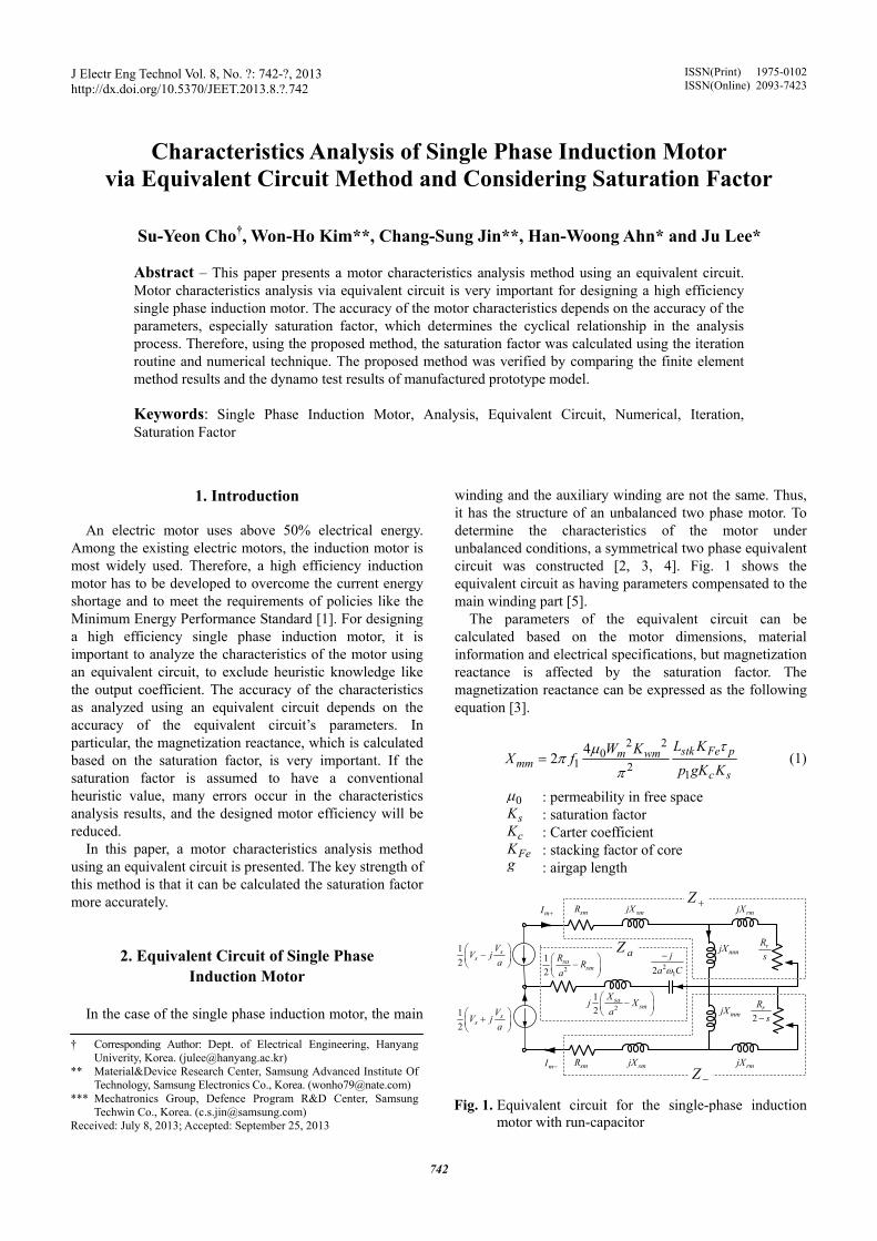
winding and the auxiliary winding are not the same. Thus, it has the structure of an unbalanced two phase motor. To determine the characteristics of the motor under unbalanced conditions, a symmetrical two phase equivalent circuit was constructed [2, 3, 4]. Fig. 1 shows the equivalent circuit as having parameters compensated to the main winding part [5].
The parameters of the equivalent circuit can be calculated based on the motor dimensions, material information and electrical specifications, but magnetization reactance is affected by the saturation factor. The magnetization reactance can be expressed as the following equation [3].
2 2
01 2
1
42 stk Fe pm wm
mmc s
L KW KX f
p gK Kτμ
ππ
= (1)
0μ : permeability in free space sK : saturation factor cK : Carter coefficient FeK : stacking factor of core
g : airgap length
† Corresponding Author: Dept. of Electrical Engineering, Hanyang Univerity, Korea. ([email protected])
** Material&Device Research Center, Samsung Advanced Institute Of Technology, Samsung Electronics Co., Korea. ([email protected])
*** Mechatronics Group, Defence Program R&D Center, Samsung Techwin Co., Korea. ([email protected])
Received: July 8, 2013; Accepted: September 25, 2013
ISSN(Print) 1975-0102ISSN(Online) 2093-7423
smR
smjX rmjX
mmjX rRs
2rRs−
12
ss
VV j
a⎛ ⎞
−⎜ ⎟⎝ ⎠
12
ss
VV j
a⎛ ⎞
+⎜ ⎟⎝ ⎠
212
sasm
RR
a⎛ ⎞−⎜ ⎟⎝ ⎠
212
sasm
Xj X
a⎛ ⎞
−⎜ ⎟⎝ ⎠
212
ja Cω−aZ
mI −
mI + smR
smjX
mmjX
rmjX
Z +
Z −
Fig. 1. Equivalent circuit for the single-phase induction motor with run-capacitor

Su-Yeon Cho, Won-Ho Kim, Chang-Sung Jin, Han-Woong Ahn and Ju Lee
743
stkL : stack length pτ : pole pitch mW : number of turns for main winding wmK : winding factor of main winding
1f : stator frequency 1p : pole pair
As the accuracy of the motor characteristics depends on
the accuracy of the saturation factor, it is very important to determine the saturation factor accurately.
3. Saturation factor The saturation factor is defined as the following:
2( ) ( )
12
ts tr cs crs
g
F F F FK
F+ + +
= + (2)
gF : magnetomotive force in airgap ,ts trF : magnetomotive force in teeth of stator, rotor ,cs crF : magnetomotive force in yoke of stator, rotor
To calculate the saturation factor, the magnetomotive
force in each part of the motor must be determined. For this step, the magnetic circuit method was used. The total magnetomotive force of the induction motor can be expressed as the following equation [3].
1 0 11
1
2 2 wW I KF
pπ= (3)
0I : maximum current value at no load To calculate the magnetomotive force in each part of the
motor, the airgap magnetic flux density should be considered. Unlike the three phase induction motor, in the case of the single phase induction motor, the phase difference between the main winding current and the auxiliary winding current should be considered for the airgap magnetic flux density. The airgap magnetic flux density equation can be expressed as following:
01 1 1
01 1
cos cos
cos( )cos( / 2)
g m esc s
a esc s
B F tgK K
F tgK K
μω θ
μω γ θ π
=
+ + + (4)
1mF : magnetomotive force of main winding 1aF : magnetomotive force of auxiliary winding
γ : phase difference between main winding current and auxiliary winding current
esθ : electrical angle of stator position 1ω : stator angular speed
When using the equivalent circuit, the phase difference
should be considered. Thus, the saturation factor required
again. Thus, the saturation factor determined the cyclical relationship in the process. Based on this cyclical relationship, the iteration routine and the numerical technique were applied.
4. Iteration Routine and Numerical Technique Fig. 2 shows the iteration routine for the more accurate
calculation of the saturation factor. For the basic designed model, the iteration routine starts the calculation process with an initial saturation factor value. After the analysis of the motor characteristics through the equivalent circuit, the airgap magnetic flux density is recalculated with the main and auxiliary winding currents and the phase difference between them. Using the recalculated airgap magnetic flux density, N+1 step value of the saturation factor is computed. The convergence condition of the iteration routine is that the error between the N+1 step value and the N step value is lower than the criterion.
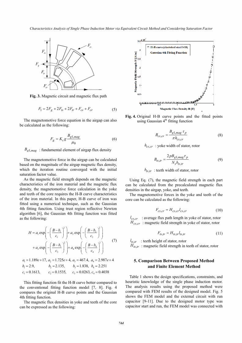
In the process, the magnetomotive force in each part can be obtained through the magnetic circuit method. Fig. 3 shows the magnetic circuit and magnetic flux path of the induction motor.
Using the magnetic circuit method, the total magneto-motive force can be calculated as the following:
Fig. 2. Flow chart of the iteration routine for considering the saturation factor
Characteristics Analysis of Single Phase Induction Motor via Equivalent Circuit Method and Considering Saturation Factor
744
1 2 2 2g ts tr cs crF F F F F F= + + + + (5) The magnetomotive force equation in the airgap can also
be calculated as the following:
1,
0
g magg c
BF K g
μ= (6)
1,g magB : fundamental element of airgap flux density The magnetomotive force in the airgap can be calculated
based on the magnitude of the airgap magnetic flux density, which the iteration routine converged with the initial saturation factor value.
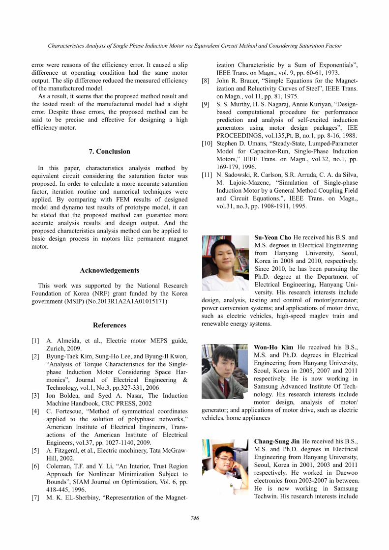
As the magnetic field strength depends on the magnetic characteristics of the iron material and the magnetic flux density, the magnetomotive force calculation in the yoke and teeth of the core requires the H-B curve characteristics of the iron material. In this paper, H-B curve of iron was fitted using a numerical technique, such as the Gaussian 4th fitting function. Using trust region reflective Newton algorithm [6], the Gaussian 4th fitting function was fitted as the following:
2 2
1 21 2
1 2
2 2
3 43 4
3 4
exp exp
exp exp
B b B bH a ac c
B b B ba ac c
⎛ ⎞ ⎛ ⎞⎛ ⎞ ⎛ ⎞− −⎜ ⎟ ⎜ ⎟= − + −⎜ ⎟ ⎜ ⎟⎜ ⎟ ⎜ ⎟⎝ ⎠ ⎝ ⎠⎝ ⎠ ⎝ ⎠⎛ ⎞ ⎛ ⎞⎛ ⎞ ⎛ ⎞− −⎜ ⎟ ⎜ ⎟+ − + −⎜ ⎟ ⎜ ⎟⎜ ⎟⎜ ⎟ ⎝ ⎠⎝ ⎠ ⎝ ⎠⎝ ⎠
(7)
1 2 3 4
1 2 3 4
1 2 3 4
1.189 17, 1.725 4, 467.4, 2.987 42.9, 2.135, 1.838, 2.2510.1613, 0.1535, 0.0263, 0.4038
a e a e a a eb b b bc c c c
= + = + = = +
= = = =
= = = =
This fitting function fit the H-B curve better compared to
the conventional fitting function model [7, 8]. Fig. 4 compares the original H-B curve points and the Gaussian 4th fitting function.
The magnetic flux densities in yoke and teeth of the core can be expressed as the following:
1,
,,
g mag pcs cr
cs cr
BB
hτ
π= (8)
,cs crh : yoke width of stator, rotor
1,
,,
2 g mag pts tr
s ts tr
pBB
N bτ
= (9)
,ts trb : teeth width of stator, rotor Using Eq. (7), the magnetic field strength in each part
can be calculated from the precalculated magnetic flux densities in the airgap, yoke, and teeth.
The magnetomotive forces in the yoke and teeth of the core can be calculated as the following:
, , ,cs cr cs cr cs crF H l= (10)
,cs crl : average flux path length in yoke of stator, rotor ,cs crH : magnetic field strength in yoke of stator, rotor
, , ,ts tr ts tr ts trF H l= (11)
,ts trl : teeth height of stator, rotor ,ts trH : magnetic field strength in teeth of stator, rotor
5. Comparison Between Proposed Method and Finite Element Method
Table 1 shows the design specifications, constraints, and
heuristic knowledge of the single phase induction motor. The analysis results using the proposed method were compared with FEM results of the designed model. Fig. 5 shows the FEM model and the external circuit with run capacitor [9-11]. Due to the designed motor type was capacitor start and run, the FEM model was connected with
csF
tsF
trF
gF
crF
Fig. 3. Magnetic circuit and magnetic flux path
Fig. 4. Original H-B curve points and the fitted points
using Gaussian 4th fitting function

Su-Yeon Cho, Won-Ho Kim, Chang-Sung Jin, Han-Woong Ahn and Ju Lee
745
the external circuit, including run capacitor. Using the proposed method and FEM analysis, the airgap magnetic flux density was calculated. Fig. 6 shows the airgap magnetic flux density. The error between the magnetic flux density results was less than 10%. Table 2 compares the results. Except for the rotor loss, the results were very close.
6. Manufactured Model and Test Results
The prototype model was manufactured to compare the
results of the proposed method. The rotor of the prototype model had aluminum die-casting rotor bars. Fig. 7 shows the prototype model.
As no standards have been established for the loss separation test method for the single phase induction motor, the input power, output power, and efficiency were measured using a dynamo test set and a power analyzer, under the state of saturated temperature.
Table 3 shows the comparison. There seems to be a little difference between the measurements and the analysis results using the proposed method. It is for this reason that the motor test condition was set to meet the equal output power for efficiency comparison. The efficiency of the prototype motor was determined to be 6% lower than the value obtained through the proposed method. It is thought that self-cooling fan loss, centrifugal force switch that is a device adjoined to the motor’s rotor, automatically changes from start capacitor to run capacitor and the manufacturing
Table 1. Design specifications, constraints, and heuristic knowledge
Spec. & Parameters Value[Unit] Rated power 1.12 kW
Number of pole 4 Rated voltage 220 Vrms
Frequency 60 Hz Type Capacitor start & run
Magnetic flux density in teeth 1.3T Stator / rotor slots 36/48
Slot fill factor 45% Minimum current density 4.5 A/mm2
Fig. 5. The finite element model and the external circuit
with run-capacitor
Fig. 6. Airgap magnetic flux densities from the finite
element method and the proposed method
(a) Stator core and frame (b) Al die-casting rotor
Fig. 7. Manufactured prototype model
Table 3. Comparison of results using the proposed method and dynamo test results of the manufactured motor
Proposed method Test results Torque 6.06 Nm 6.05 Nm Speed 1766 RPM 1735 RPM
Input power 1246.5 W 1320 W Output power 1120.7 W 1110 W
Efficiency 89.9 % 84.14 %
Table 2. Analysis results using the proposed method and finite element method
Proposed method Finite element method
Torque 6.06 Nm 6.28 Nm Speed 1766 RPM 1760 RPM Power 1120.6 W 1128.2 W
Stator copper loss 64.23 W 69.53 W Rotor Al loss 23 W 47.3 W
Iron loss 30 W 29.73 W Efficiency 89.9 % 88.5 %
Power factor 0.968 0.965
Characteristics Analysis of Single Phase Induction Motor via Equivalent Circuit Method and Considering Saturation Factor
746
error were reasons of the efficiency error. It caused a slip difference at operating condition had the same motor output. The slip difference reduced the measured efficiency of the manufactured model.
As a result, it seems that the proposed method result and the tested result of the manufactured model had a slight error. Despite those errors, the proposed method can be said to be precise and effective for designing a high efficiency motor.
7. Conclusion In this paper, characteristics analysis method by
equivalent circuit considering the saturation factor was proposed. In order to calculate a more accurate saturation factor, iteration routine and numerical techniques were applied. By comparing with FEM results of designed model and dynamo test results of prototype model, it can be stated that the proposed method can guarantee more accurate analysis results and design output. And the proposed characteristics analysis method can be applied to basic design process in motors like permanent magnet motor.
Acknowledgements This work was supported by the National Research
Foundation of Korea (NRF) grant funded by the Korea government (MSIP) (No.2013R1A2A1A01015171)
References
[1] A. Almeida, et al., Electric motor MEPS guide, Zurich, 2009.
[2] Byung-Taek Kim, Sung-Ho Lee, and Byung-Il Kwon, “Analysis of Torque Characteristics for the Single-phase Induction Motor Considering Space Har-monics”, Journal of Electrical Engineering & Technology, vol.1, No.3, pp.327-331, 2006
[3] Ion Boldea, and Syed A. Nasar, The Induction Machine Handbook, CRC PRESS, 2002
[4] C. Fortescue, “Method of symmetrical coordinates applied to the solution of polyphase networks,” American Institute of Electrical Engineers, Trans-actions of the American Institute of Electrical Engineers, vol.37, pp. 1027-1140, 2009.
[5] A. Fitzgeral, et al., Electric machinery, Tata McGraw-Hill, 2002.
[6] Coleman, T.F. and Y. Li, “An Interior, Trust Region Approach for Nonlinear Minimization Subject to Bounds”, SIAM Journal on Optimization, Vol. 6, pp. 418-445, 1996.
[7] M. K. EL-Sherbiny, “Representation of the Magnet-
ization Characteristic by a Sum of Exponentials”, IEEE Trans. on Magn., vol. 9, pp. 60-61, 1973.
[8] John R. Brauer, “Simple Equations for the Magnet-ization and Reluctivity Curves of Steel”, IEEE Trans. on Magn., vol.11, pp. 81, 1975.
[9] S. S. Murthy, H. S. Nagaraj, Annie Kuriyan, “Design-based computational procedure for performance prediction and analysis of self-excited induction generators using motor design packages”, IEE PROCEEDINGS, vol.135,Pt. B, no.1, pp. 8-16, 1988.
[10] Stephen D. Umans, “Steady-State, Lumped-Parameter Model for Capacitor-Run, Single-Phase Induction Motors,” IEEE Trans. on Magn., vol.32, no.1, pp. 169-179, 1996.
[11] N. Sadowski, R. Carlson, S.R. Arruda, C. A. da Silva, M. Lajoic-Mazcnc, “Simulation of Single-phase Induction Motor by a General Method Coupling Field and Circuit Equations.”, IEEE Trans. on Magn., vol.31, no.3, pp. 1908-1911, 1995.
Su-Yeon Cho He received his B.S. and M.S. degrees in Electrical Engineering from Hanyang University, Seoul, Korea in 2008 and 2010, respectively. Since 2010, he has been pursuing the Ph.D. degree at the Department of Electrical Engineering, Hanyang Uni-versity. His research interests include
design, analysis, testing and control of motor/generator; power conversion systems; and applications of motor drive, such as electric vehicles, high-speed maglev train and renewable energy systems.
Won-Ho Kim He received his B.S., M.S. and Ph.D. degrees in Electrical Engineering from Hanyang University, Seoul, Korea in 2005, 2007 and 2011 respectively. He is now working in Samsung Advanced Institute Of Tech-nology. His research interests include motor design, analysis of motor/
generator; and applications of motor drive, such as electric vehicles, home appliances
Chang-Sung Jin He received his B.S., M.S. and Ph.D. degrees in Electrical Engineering from Hanyang University, Seoul, Korea in 2001, 2003 and 2011 respectively. He worked in Daewoo electronics from 2003-2007 in between. He is now working in Samsung Techwin. His research interests include
Su-Yeon Cho, Won-Ho Kim, Chang-Sung Jin, Han-Woong Ahn and Ju Lee
747
motor design, analysis of motor/generator; power conversion systems; and applications of motor/generator, such as vehicles, automated drive system
Han-Woong Ahn He received his B.S. and M.S. degrees in Electrical Engin-eering from Hanyang University, Seoul, Korea in 2010 and 2012, respectively. Since 2012, he has been pursuing the Ph.D. degree at the Department of Electrical Engineering, Hanyang Uni-versity. His research interests include
testing and control of motor/generator; DSP control systems; and power applications of motor drive.
Ju Lee He received his M.S. degree from Hanyang University, Seoul, South Korea, in 1988, and his Ph.D. from Kyusyu University, Japan in 1997, both in Electrical Engineering, He joined Hanyang University in Sep-tember, 1997 and is currently a Professor of the Division of Electrical
and Biomedical Engineering. His main research interests include electric machinery and its drives, electromagnetic field analysis, new transformation systems such as hybrid electric vehicles (HEV), and high-speed electric trains and standardization. He is a member of the IEEE Industry Applications Society, Magnetics Society, and Power Electronics Society.
Recommended