GreenRoad Installation Document (GRID) Document Number: VWR10
Chassis: Volvo B10BLE Version Created By Date
Body: Wright Renown 1.0 JP 15/06/2011
Year: 1998/2000
Configuration: Single Deck Bus
Adherence to the installation process outlined within the GreenRoad Installation Document (GRID) will
ensure that all policies and procedures required by GreenRoad are achieved:
• Specific client requirements are addressed.
• Hardware placement is optimised for system performance, allowing predefined hardware profiles to be
chosen accurately, which is critical for solution functionality.
• Installation practices will not contravene hardware warranty requirements.
No changes to the installation process outlined within this GRID will be permitted unless authorised in
writing. Any proposed changes must be communicated to and agreed by the GreenRoad Field Operations
Manager prior to installation. This will ensure that if required, any profile adjustments can be considered in
consultation with the client and GreenRoad Technical.
Any changes to vehicle specifications which subsequently create inaccuracies within this GRID must be
communicated to the GreenRoad Field Operations Manager. Pictures and detailed notes will assist us to
ensure accuracy when making amendments to this documentation.

GreenRoad Live® - General Information
• System Specifications:
Operating voltage ……………9-30 V
Operating temperature………-20 to 80 C
• Current Consumption:
Standby……….………... >10mA
Normal…………………. 50-70mA
Transmit……………..….. 200 mA (Avg)
• Lead Specification:
Red: Positive 9-30V
2A ATO fused connection to permanent Live circuit
Black: Negative / Chassis
2A ATO fused connection to GND circuit
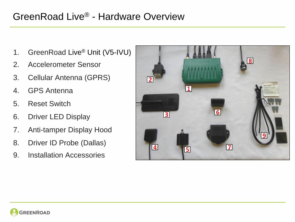
GreenRoad Live® - Hardware Overview
1. GreenRoad Live® Unit (V5-IVU)
2. Accelerometer Sensor
3. Cellular Antenna (GPRS)
4. GPS Antenna
5. Reset Switch
6. Driver LED Display
7. Anti-tamper Display Hood
8. Driver ID Probe (Dallas)
9. Installation Accessories
GreenRoad Live® Unit
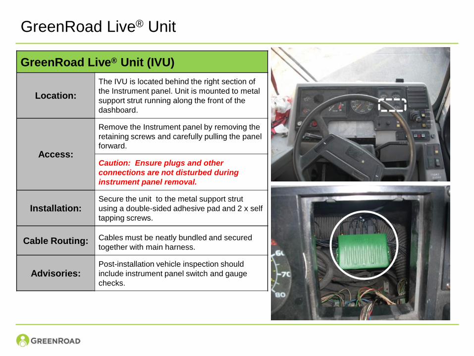
GreenRoad Live® Unit (IVU)
Location:
The IVU is located behind the right section of
the Instrument panel. Unit is mounted to metal
support strut running along the front of the
dashboard.
Access:
Remove the Instrument panel by removing the
retaining screws and carefully pulling the panel
forward.
Caution: Ensure plugs and other
connections are not disturbed during
instrument panel removal.
Installation:Secure the unit to the metal support strut
using a double-sided adhesive pad and 2 x self
tapping screws.
Cable Routing: Cables must be neatly bundled and secured
together with main harness.
Advisories:Post-installation vehicle inspection should
include instrument panel switch and gauge
checks.
Drivers LED Display
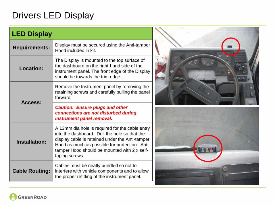
LED Display
Requirements:Display must be secured using the Anti-tamper
Hood included in kit.
Location:
The Display is mounted to the top surface of
the dashboard on the right-hand side of the
instrument panel. The front edge of the Display
should be towards the trim edge.
Access:
Remove the Instrument panel by removing the
retaining screws and carefully pulling the panel
forward.
Caution: Ensure plugs and other
connections are not disturbed during
instrument panel removal.
Installation:
A 13mm dia hole is required for the cable entry
into the dashboard. Drill the hole so that the
display cable is retained under the Anti-tamper
Hood as much as possible for protection. Anti-
tamper Hood should be mounted with 2 x self-
taping screws.
Cable Routing:Cables must be neatly bundled so not to
interfere with vehicle components and to allow
the proper refitting of the instrument panel.
GPRS Antenna
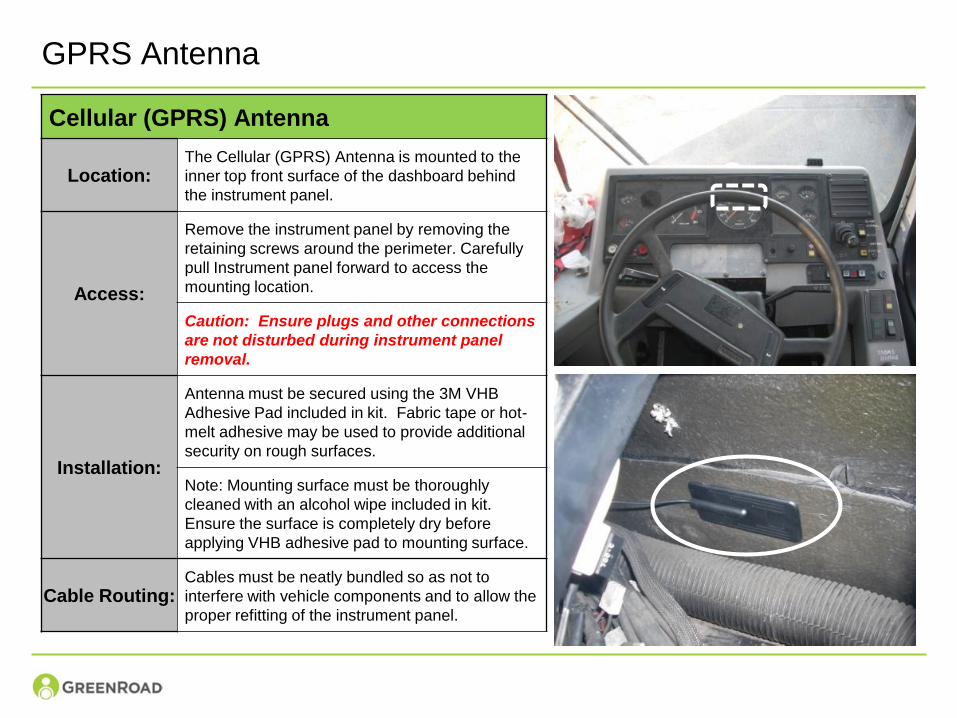
Cellular (GPRS) Antenna
Location:The Cellular (GPRS) Antenna is mounted to the
inner top front surface of the dashboard behind
the instrument panel.
Access:
Remove the instrument panel by removing the
retaining screws around the perimeter. Carefully
pull Instrument panel forward to access the
mounting location.
Caution: Ensure plugs and other connections
are not disturbed during instrument panel
removal.
Installation:
Antenna must be secured using the 3M VHB
Adhesive Pad included in kit. Fabric tape or hot-
melt adhesive may be used to provide additional
security on rough surfaces.
Note: Mounting surface must be thoroughly
cleaned with an alcohol wipe included in kit.
Ensure the surface is completely dry before
applying VHB adhesive pad to mounting surface.
Cable Routing:Cables must be neatly bundled so as not to
interfere with vehicle components and to allow the
proper refitting of the instrument panel.
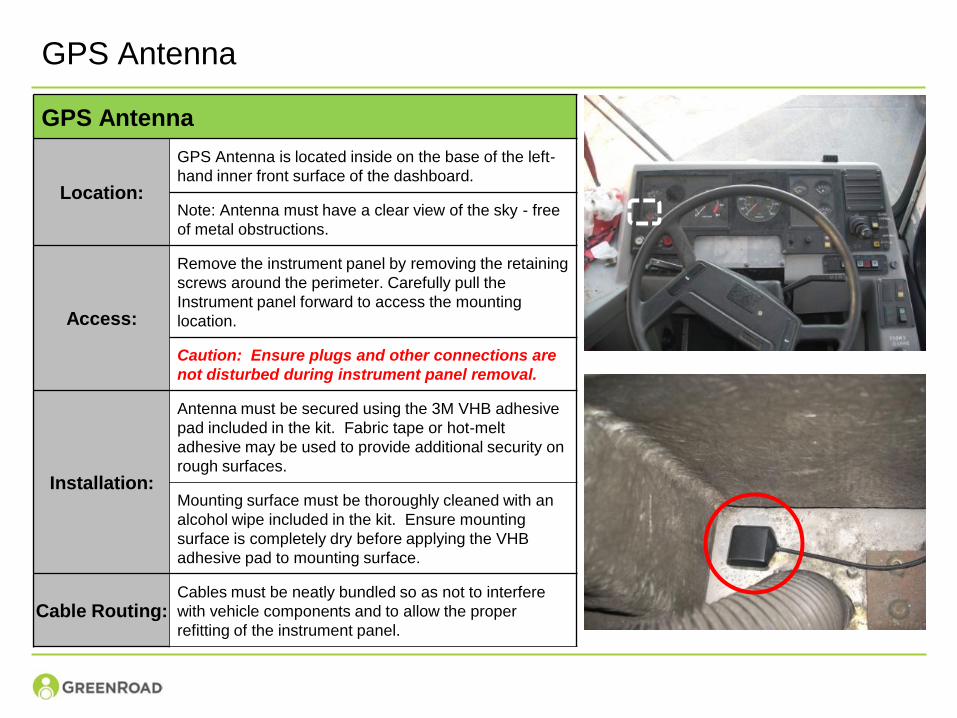
GPS Antenna
GPS Antenna
Location:
GPS Antenna is located inside on the base of the left-
hand inner front surface of the dashboard.
Note: Antenna must have a clear view of the sky - free
of metal obstructions.
Access:
Remove the instrument panel by removing the retaining
screws around the perimeter. Carefully pull the
Instrument panel forward to access the mounting
location.
Caution: Ensure plugs and other connections are
not disturbed during instrument panel removal.
Installation:
Antenna must be secured using the 3M VHB adhesive
pad included in the kit. Fabric tape or hot-melt
adhesive may be used to provide additional security on
rough surfaces.
Mounting surface must be thoroughly cleaned with an
alcohol wipe included in the kit. Ensure mounting
surface is completely dry before applying the VHB
adhesive pad to mounting surface.
Cable Routing:Cables must be neatly bundled so as not to interfere
with vehicle components and to allow the proper
refitting of the instrument panel.
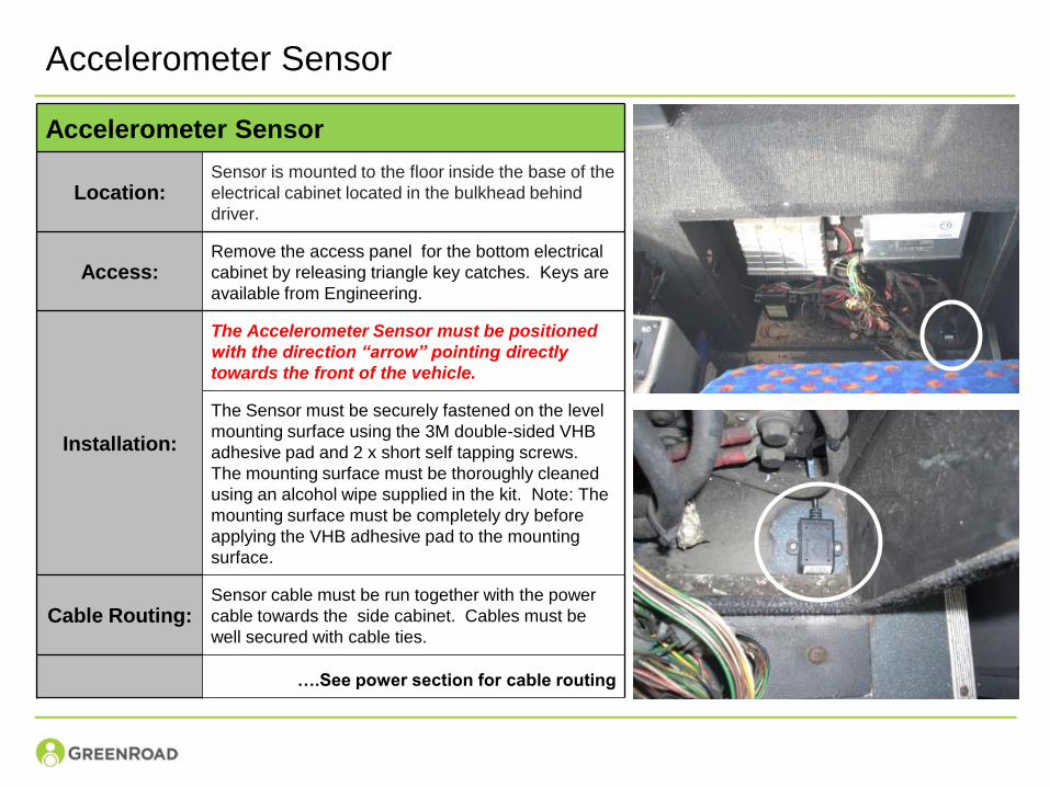
Accelerometer Sensor
Accelerometer Sensor
Location:Sensor is mounted to the floor inside the base of the
electrical cabinet located in the bulkhead behind
driver.
Access:Remove the access panel for the bottom electrical
cabinet by releasing triangle key catches. Keys are
available from Engineering.
Installation:
The Accelerometer Sensor must be positioned
with the direction “arrow” pointing directly
towards the front of the vehicle.
The Sensor must be securely fastened on the level
mounting surface using the 3M double-sided VHB
adhesive pad and 2 x short self tapping screws.
The mounting surface must be thoroughly cleaned
using an alcohol wipe supplied in the kit. Note: The
mounting surface must be completely dry before
applying the VHB adhesive pad to the mounting
surface.
Cable Routing:Sensor cable must be run together with the power
cable towards the side cabinet. Cables must be
well secured with cable ties.
….See power section for cable routing
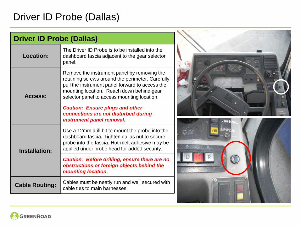
Driver ID Probe (Dallas)
Driver ID Probe (Dallas)
Location:The Driver ID Probe is to be installed into the
dashboard fascia adjacent to the gear selector
panel.
Access:
Remove the instrument panel by removing the
retaining screws around the perimeter. Carefully
pull the instrument panel forward to access the
mounting location. Reach down behind gear
selector panel to access mounting location.
Caution: Ensure plugs and other
connections are not disturbed during
instrument panel removal.
Installation:
Use a 12mm drill bit to mount the probe into the
dashboard fascia. Tighten dallas nut to secure
probe into the fascia. Hot-melt adhesive may be
applied under probe head for added security.
Caution: Before drilling, ensure there are no
obstructions or foreign objects behind the
mounting location.
Cable Routing:Cables must be neatly run and well secured with
cable ties to main harnesses.
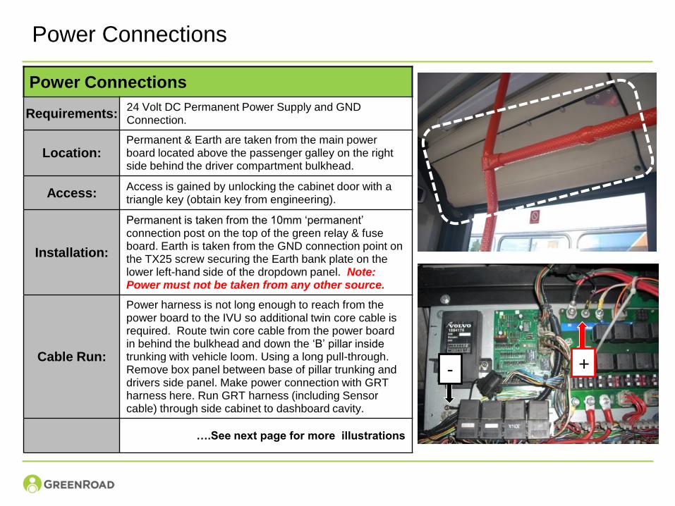
Power Connections
Power Connections
Requirements:24 Volt DC Permanent Power Supply and GND Connection.
Location: Permanent & Earth are taken from the main power board located above the passenger galley on the right side behind the driver compartment bulkhead.
Access: Access is gained by unlocking the cabinet door with a triangle key (obtain key from engineering).
Installation:
Permanent is taken from the 10mm ‘permanent’ connection post on the top of the green relay & fuse board. Earth is taken from the GND connection point on the TX25 screw securing the Earth bank plate on the lower left-hand side of the dropdown panel. Note: Power must not be taken from any other source.
Cable Run:
Power harness is not long enough to reach from the power board to the IVU so additional twin core cable is required. Route twin core cable from the power board in behind the bulkhead and down the ‘B’ pillar inside trunking with vehicle loom. Using a long pull-through. Remove box panel between base of pillar trunking and drivers side panel. Make power connection with GRT harness here. Run GRT harness (including Sensor cable) through side cabinet to dashboard cavity.
….See next page for more illustrations
- +
Power Connections (Cont.)
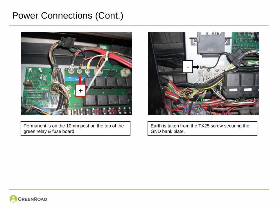
Permanent is on the 10mm post on the top of the
green relay & fuse board.
Earth is taken from the TX25 screw securing the
GND bank plate.
-
+
Power Connections (Cont.)
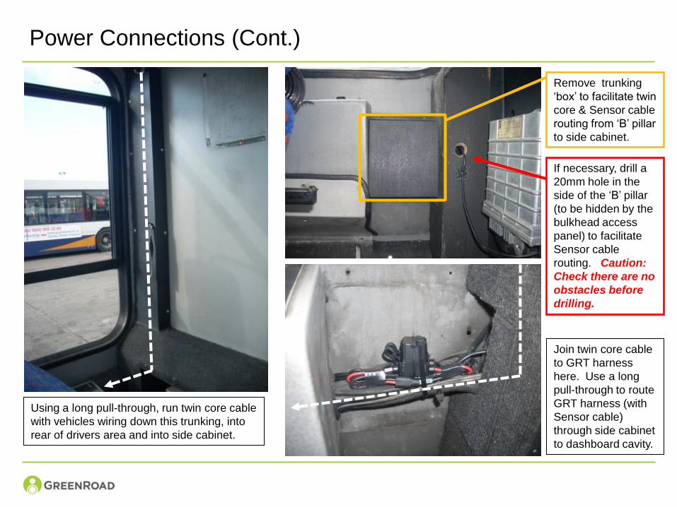
Using a long pull-through, run twin core cable
with vehicles wiring down this trunking, into
rear of drivers area and into side cabinet.
Join twin core cable
to GRT harness
here. Use a long
pull-through to route
GRT harness (with
Sensor cable)
through side cabinet
to dashboard cavity.
Remove trunking
‘box’ to facilitate twin
core & Sensor cable
routing from ‘B’ pillar
to side cabinet.
If necessary, drill a
20mm hole in the
side of the ‘B’ pillar
(to be hidden by the
bulkhead access
panel) to facilitate
Sensor cable
routing. Caution:
Check there are no
obstacles before
drilling.
Reset Switch
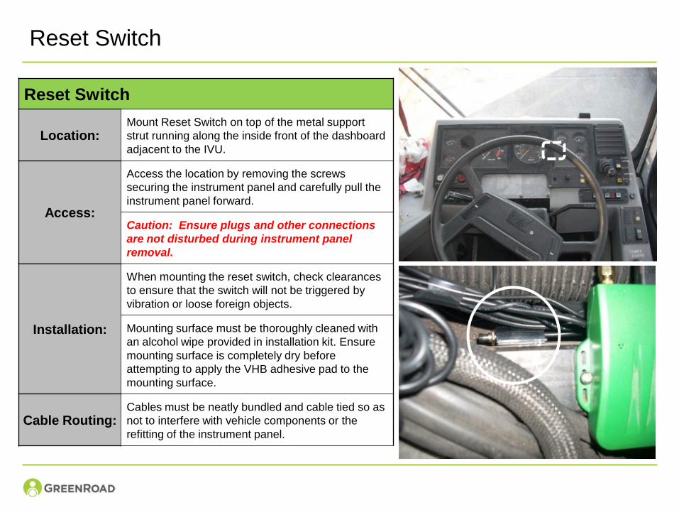
Reset Switch
Location:Mount Reset Switch on top of the metal support
strut running along the inside front of the dashboard
adjacent to the IVU.
Access:
Access the location by removing the screws
securing the instrument panel and carefully pull the
instrument panel forward.
Caution: Ensure plugs and other connections
are not disturbed during instrument panel
removal.
Installation:
When mounting the reset switch, check clearances
to ensure that the switch will not be triggered by
vibration or loose foreign objects.
Mounting surface must be thoroughly cleaned with
an alcohol wipe provided in installation kit. Ensure
mounting surface is completely dry before
attempting to apply the VHB adhesive pad to the
mounting surface.
Cable Routing:Cables must be neatly bundled and cable tied so as
not to interfere with vehicle components or the
refitting of the instrument panel.
Support Contact
For Technical Support regarding the configuration and use of
the Installer Suite please contact:
John Perry
Operations Manager
Tel: +44 (0)7985 229 365
GreenRoad Technical Support
Tel: +44 (0)207 886 0830
Recommended