Page 1 of 18 Scheme: CAZ Clean Vehicle Retrofit Certification Title: Chassis Dynamometer Test Procedures for Approval of Low Emission Adaptations Version: 7.0 Date of Issue: 09 February 2018
Clean Air Zone (CAZ) - CLEAN VEHICLE RETROFIT CERTIFICATION (CVRC)
CHASSIS DYNAMOMETER TEST PROCEDURES FOR APPROVAL OF LOW
EMISSION ADAPTATIONS
Test procedures for measuring pollutant and greenhouse gas emissions of
conventionally-powered (pre-Euro VI/6 diesel) vehicles equipped with retrofitted low
emission adaptation equipment (intended to meet or exceed Euro VI/6 in-service
performance) on chassis dynamometers.
Page 2 of 18 Scheme: CAZ Clean Vehicle Retrofit Certification Title: Chassis Dynamometer Test Procedures for Approval of Low Emission Adaptations Version: 7.0 Date of Issue: 09 February 2018
Contents 1. Scope ............................................................................................................................................. 4
2. Test preparations ......................................................................................................................... 4
Test site ............................................................................................................................................. 4
Pre-test data collection .................................................................................................................... 4
Operation of the vehicle .................................................................................................................. 5
Condition of the Vehicle .................................................................................................................. 5
Dynamometer Specifications .......................................................................................................... 5
Dynamometer Calibrations ............................................................................................................. 6
Inertial Load ...................................................................................................................................... 6
Road Load ......................................................................................................................................... 6
Dynamometer Load Coefficient Determination ............................................................................ 6
Dynamometer Settings .................................................................................................................... 6
Test Instrumentation ........................................................................................................................ 6
3. Test Procedure ............................................................................................................................. 6
Vehicle Propulsion System Starting and Restarting ................................................................... 6
Dynamometer Driving Procedure .................................................................................................. 6
Dynamometer Warm-up .................................................................................................................. 7
Practice and Warm Up Runs .......................................................................................................... 7
Emission Tests ................................................................................................................................. 7
Test Termination............................................................................................................................... 7
Data Recording ................................................................................................................................. 7
Deviations from Standard Procedure ............................................................................................ 8
4. Test validation ............................................................................................................................... 8
5. Reporting ....................................................................................................................................... 8
Annex 1. Detailed test conditions; buses ...................................................................................... 10
Vehicle Loading .............................................................................................................................. 10
Test cycle ........................................................................................................................................ 10
Auxillary Loads ............................................................................................................................... 10
Annex 2. Detailed test conditions; coaches .................................................................................. 11
Vehicle Loading .............................................................................................................................. 11
Test cycle ........................................................................................................................................ 11
Auxillary Loads ............................................................................................................................... 11
Annex 3. Detailed test conditions; HGVs (N2 & N3) ..................................................................... 12
Page 3 of 18 Scheme: CAZ Clean Vehicle Retrofit Certification Title: Chassis Dynamometer Test Procedures for Approval of Low Emission Adaptations Version: 7.0 Date of Issue: 09 February 2018
Vehicle Loading .............................................................................................................................. 12
Test cycle ........................................................................................................................................ 12
Auxillary Loads ............................................................................................................................... 12
Annex 4. Detailed test conditions; Vans (N1) ................................................................................ 13
Vehicle Loading .............................................................................................................................. 13
Test cycle ........................................................................................................................................ 13
Auxillary Loads ............................................................................................................................... 13
Annex 5. Detailed test conditions; Taxis (Black Cabs) (M1, GVW over 2t) .............................. 14
Vehicle Loading .............................................................................................................................. 14
Test cycle ........................................................................................................................................ 14
Vehicle Loading .............................................................................................................................. 15
Test cycle ........................................................................................................................................ 15
Auxillary Loads ............................................................................................................................... 15
Annex 6. Emission limits permitted from the vehicle fitted with the low emission adaptation
.......................................................................................................................................................... 16
Limits applying to buses, coaches and HGVs (N2 and N3) ................................................. 16
Limits applying to Vans (N1) ..................................................................................................... 16
Limits applying to Taxis (Black Cabs) ..................................................................................... 17
Secondary emissions ................................................................................................................. 17
Nitrous oxide and methane (N2O and CH4) as CO2 equivalent (CO2e) .............................. 17
Carbon dioxide (CO2)................................................................................................................. 17
Ammonia (NH3) ........................................................................................................................... 18
Page 4 of 18 Scheme: CAZ Clean Vehicle Retrofit Certification Title: Chassis Dynamometer Test Procedures for Approval of Low Emission Adaptations Version: 7.0 Date of Issue: 09 February 2018
1. Scope
This document provides an accurate and reproducible procedure for simulating the operation
of vehicles powered by conventional (diesel) powertrains on dynamometers for the purpose
of measuring emissions and to evaluate the efficacy of retrofitted equipment, as part of the
Clean Vehicle Retrofit Accreditation Scheme (CVRAS).
It should be noted that the vehicles addressed in this recommended practice are expected to
be powered by diesel engines certified to any one of the pre-EuroVI/6 standards.
This generic test procedure does not make specific provisions or recommendations for
testing of individual vehicle types – requirements for each vehicle type, including test cycles,
emissions limit values and use of auxiliary loads, air conditioning, heating systems, PTOs,
etc, are contained within the relevant annexes.
The intention is to test the vehicle in its normal road-going condition and operating strategy
as far as reasonably practical, within the constraints of the equipment and cycle. Potential
exceptions to this include antilock brakes and traction control. Any aspect of vehicle
operation which needs to be modified for the test shall be discussed with the test centre and
recorded in the test report.
As well as measuring pollutant emissions performance to determine if the vehicle achieves
Euro VI/6 equivalence, specifically for NOx and PM, the procedure requires the calculation of
Tank-to-Wheel (TTW) Greenhouse Gas (GHG) emissions to determine if the retrofit system
incurs unacceptable increases in such emissions.
Regulated emissions (HC, NH3, CO, NO, NO2, and PM) and GHG emissions (CO2, N2O and
CH4) shall be sampled over the entire cycle and the results presented as g/km.
Vehicles too heavy or for any other reason not able to be tested on a chassis dynamometer
shall instead be tested according to the (separate) track-based test protocols.
2. Test preparations
Test site
The ambient temperature levels encountered by the test vehicle in the dynamometer
laboratory shall be maintained at 18°C+/- 2°C throughout the test.
Ambient temperatures must be recorded at the beginning and end of the test period.
Adequate test site capabilities for safe venting and cooling of batteries, containment of
flywheels, protection from exposure to high voltage, or any other necessary safety
precaution shall be provided during testing.
One or more speed tracking fans shall direct cooling air to the vehicle in an attempt to
maintain the engine operating temperature as specified by the manufacturer during testing.
These fans shall only be operating when the vehicle is in operation and shall be switched off
for all key-off dwell periods. Fans for brake cooling can be utilized at all times. Additional
fixed speed fans should be used if required and must be documented in the test report.
Pre-test data collection
Prior to testing, detailed characteristics of the vehicle should be recorded, including details of
the retrofitted equipment, as defined in Appendix 1.
Page 5 of 18 Scheme: CAZ Clean Vehicle Retrofit Certification Title: Chassis Dynamometer Test Procedures for Approval of Low Emission Adaptations Version: 7.0 Date of Issue: 09 February 2018
For all tests, a fuel sample shall be taken for potential analysis at a later date. The vehicle
will be tested using the fuel with which it arrives at the test facility. Fuels should meet the
requirements of EN590 and any exceptions to this should be advised by the technology
supplier for reporting purposes.
Operation of the vehicle
If the vehicle is unable to be driven on the chassis dynamometer in its conventional
operating mode then the reasons for this should be provided by the technology supplier in
advance of the tests for reporting purposes. Any deviations from standard operation must be
approved by the LowCVP prior to the issue of a CVRAS certificate (where appropriate).
Condition of the Vehicle
Vehicle Stabilization -- Prior to testing, the vehicle shall be stabilized to a minimum distance
of 3000km. This will be documented in the test report.
Tyres -- Manufacturer’s recommended tyres shall be used and shall be the same size as
would be used in service. This will be documented in the test report.
Tyre Pressure -- Tyre pressures should be set at the beginning of the test to manufacturer’s
recommended pressure. This will be documented in the test report.
Lubricants -- The vehicle lubricants normally specified by the manufacturer shall be used.
This specification shall be supplied by the technology supplier in advance of the tests and
recorded in the test report.
Gear Shifting – The vehicle shall be driven with appropriate accelerator pedal movement to
achieve the time versus speed relationship prescribed by the drive cycle. Both smoothing of
speed variations and excessive acceleration pedal perturbations are to be avoided and may
cause invalidation of the test run. In the case of test vehicles equipped with manual
transmissions, the transmission shall be shifted in accordance with procedures that are
representative of shift patterns that may reasonably be expected to be followed by vehicles
in use.
For these tests, it is not a requirement that test houses should follow precisely the exact gear
change points and strategies specified by Type Approval legislation that use the same
cycles (e.g. WLTP), though they may do so if they feel such an approach meets the
requirements of the preceding paragraph.
Vehicle Preparation & Preconditioning -- as a minimum, should include:
The vehicle should be preconditioned using a complete run of the test cycle followed
by the appropriate key-off dwell period
Dynamometer Specifications
The evaluation of the emissions should be performed using a laboratory that incorporates a
chassis dynamometer, a full-scale dilution tunnel, and laboratory-grade exhaust gas
analyzers as described in ECE R83 (Light-duty vehicles) and ECE R49 (Heavy-duty
engines). The chassis dynamometer should be capable of simulating the transient inertial
load, aerodynamic drag and rolling resistance associated with normal operations of the
vehicle. The transient inertial load should be simulated using appropriately sized flywheels
and/or electronically controlled power absorbers. The aerodynamic drag and rolling
resistance may be implemented by power absorbers with an appropriate computer control
system. The drag and rolling resistance should be established as a function of vehicle
Page 6 of 18 Scheme: CAZ Clean Vehicle Retrofit Certification Title: Chassis Dynamometer Test Procedures for Approval of Low Emission Adaptations Version: 7.0 Date of Issue: 09 February 2018
speed. The actual vehicle weight for the on-road coast down should be the same as the
anticipated vehicle testing weight as simulated on the dynamometer. The vehicle should be
mounted on the chassis dynamometer so that it can be driven through a test cycle. The
driver should be provided with a visual display of the desired and actual vehicle speed to
allow the driver to operate the vehicle on the prescribed cycle.
Dynamometer Calibrations
The dynamometer laboratory should provide evidence of compliance with calibration
procedures as recommended by the manufacturer.
Inertial Load
Inertial load must be simulated correctly from a complete stop (e.g., total energy used to
accelerate the vehicle plus road and aerodynamic losses should equal theoretical
calculations and actual coast-downs).
Road Load
Road load and wind losses should be simulated by an energy device such as a power
absorber. Road load should be verified by comparison to previously tested vehicles having
similar characteristics or by coast-down analysis on the track.
Dynamometer Load Coefficient Determination
The dynamometer coefficients that simulate road-load forces shall be determined as
specified in Directive ECE R83. The vehicles shall be weighted to the correct dynamometer
test weight when the on road coast-downs are performed.
Dynamometer Settings
The dynamometer’s power absorption and inertia simulation shall be set as specified in ECE
R83. It is preferable to ensure that the dynamometer system provides the appropriate
retarding force at all speeds, rather than simply satisfying a coast-down time between two
specified speeds. The remaining operating conditions of the vehicle should be set to the
same operating mode during coast-downs on road and on the dynamometer (e.g., air
conditioning, etc).
Test Instrumentation
Equipment referenced in ECE R83 and ECE R49 (including exhaust emissions sampling and
analytical systems) is required for emissions measurements, where appropriate. All
instrumentation shall be traceable. to national standards.
The chassis test laboratory will be used to measure actual cycle distance during a test.
3. Test Procedure
Vehicle Propulsion System Starting and Restarting
The vehicle’s propulsion system – specifically, the unit that provides the primary motive
energy, e.g., the internal combustion engine -- shall be started according to the
manufacturer’s recommended starting procedures in the owner’s manual. The air conditioner
and other auxiliary on-board equipment generally used during normal service shall be
activated or disabled in accordance with the specific vehicle test requirements.
Dynamometer Driving Procedure
The emission test sequence starts with a “hot” vehicle that can be utilized to warm the
dynamometer to operating temperature and allow for vehicle rolling loss calibration.
Page 7 of 18 Scheme: CAZ Clean Vehicle Retrofit Certification Title: Chassis Dynamometer Test Procedures for Approval of Low Emission Adaptations Version: 7.0 Date of Issue: 09 February 2018
Dynamometer Warm-up
The test vehicle is used to warm the dynamometer and operated to allow for proper
laboratory and vehicle loss calibrations.
Practice and Warm Up Runs
The test vehicle will be operated through a preliminary run of the desired test cycle. During
this preliminary cycle, the driver will become familiar with the vehicle operation, and the
suitability of the selected operating range of gas analysers will be verified. Additional
preliminary runs will be made, if necessary, to assure that the vehicle, driver, and laboratory
instrumentation are performing satisfactorily.
Emission Tests
During the actual emission tests the test facility shall measure all emission data from the
moment the vehicle is started, excluding the actual start event.
If the vehicle has not been operated for more than 30 minutes then it shall be started and
warmed to operating temperature utilizing the same test cycle that will be used for emission
characterization, unless a different warm-up procedure is specified in the relevant detailed
test conditions Annex. Once the vehicle is at operating temperature it shall be turned off and
will be restarted within 30 minutes. The test cycle shall then begin and emission
measurements will be taken. At the end of the test cycle the vehicle shall be returned to the
“key off” condition. Analysis will be carried out between test cycles
The number of tests runs performed must be sufficient to provide a minimum of three test
runs with valid results. If the test sequence lapses in timing, another preliminary warm up run
must be performed, after which the schedule can be resumed. Valid data gained prior to the
breaking of the schedule may be preserved and reported. It is important to adhere to the
time schedule and soak periods because engines and after-treatment devices are sensitive
to operating temperature.
Test Termination
The test shall terminate at the conclusion of the test run. However, sufficient idle time should
be included at the end of a run, such that the analysers are not missing emissions that are
still in the sampling train.
Data Recording
The emissions from the vehicle exhaust will be ducted to a full-scale dilution tunnel where
the gaseous emissions of carbon monoxide, oxides of nitrogen (both nitric oxide and
nitrogen dioxide) and carbon dioxide will be analysed as an integrated bag sample.
Emissions of hydrocarbons, methane and nitrous oxide shall be measured on a continuous
basis at a frequency of 5 Hz or greater. It is recommended that emissions of carbon
monoxide, oxides of nitrogen and carbon dioxide are also measured on a continuous basis,
and that these levels be compared to the integrated bag measurements as a quality
assurance check. Particulate matter will be measured gravimetrically using fluorocarbon-
coated glass fibre filters by weighing the filters before and after testing. Filters will be
conditioned to temperature and humidity conditions as specified by ECE R49
For each constituent, a background sample using the same sampling train as used during
the actual testing must be measured before and after the emission test, and the background
correction must be performed as specified by ECE R83. In cases where some speciality
fuels are examined by the test procedure, it may prove necessary to sample for additional
species, including alcohols, aldehydes, ketones, or organic toxics if it is suspected that the
Page 8 of 18 Scheme: CAZ Clean Vehicle Retrofit Certification Title: Chassis Dynamometer Test Procedures for Approval of Low Emission Adaptations Version: 7.0 Date of Issue: 09 February 2018
levels of these additional species might be significantly higher than is normally found for
diesel fuel. It is recommended that the tunnel inlet be filtered for PM with a HEPA filter to aid
in lowering the detection limits.
Fuel consumed shall typically be determined by carbon balance from the gas analysers, and
the actual distance travelled by the dynamometer roll surface shall be used to provide the
distance travelled during the driving cycles. Alternative methods for fuel consumption, such
as direct mass measurement of the fuel tank, shall be considered if they are sufficiently
accurate. This would require that the mass measurement system has an accuracy of greater
than 1% of the fuel amount consumed during the test cycle.
Deviations from Standard Procedure
It is permissible to deviate from the prescribed procedure in cases where it can clearly be
shown that this would result in a more realistic simulation of real-world vehicle operation.
Any deviations from the standard test procedure must be recorded in the test report and
approved by the LowCVP prior to the issue of a CVRAS certificate (where appropriate).
4. Test validation The value of the mass emission rates for each species will be averaged over the test
distance (i.e. reported in g/km). There will be a minimum of three valid runs for each type of
drive cycle. For a group of three tests to be valid the 'total GHG emissions' from each test,
must lie within a 5% range (max <= 1.05 x min). Any obvious error in the data should be
identified and removed from the dataset; however, a minimum of three successful runs
should be used in reporting the data.
At the end of each run, the total distance travelled by the vehicle over the test run will be
noted from the dynamometer distance measurements. Adherence of the driver to the test
cycle target speeds will be noted, and a regression will be performed to compare actual
speeds with target speeds on a second-by-second basis. Target speed (x) and actual speed
(y) should be charted in 1Hz increments and a trend line inserted with a zero intercept. If the
resulting trend line has a slope that varies from unity by more than 10% or an R2 of less than
0.8 the test run should be considered an invalid representation of that test cycle. The actual
distance travelled by the dynamometer roller(s) should be used for the test cycle distance
value.
If at any point during the test, vehicle propulsion is not possible or the driver is warned by the
vehicle to discontinue driving then the test is considered invalid.
5. Reporting The final test report shall include all measured parameters including vehicle configuration,
vehicle statistics, test cycle, measured parameters and calculated test results.
The following information will be included in the report:
Technology name, vehicle to which fitted and technology supplier’s name and address.
Name of Technical Service carrying out the test, test cycles used and date(s) tested.
Essential vehicle and technology characteristics.
Name and organization of test witness(es).
Page 9 of 18 Scheme: CAZ Clean Vehicle Retrofit Certification Title: Chassis Dynamometer Test Procedures for Approval of Low Emission Adaptations Version: 7.0 Date of Issue: 09 February 2018
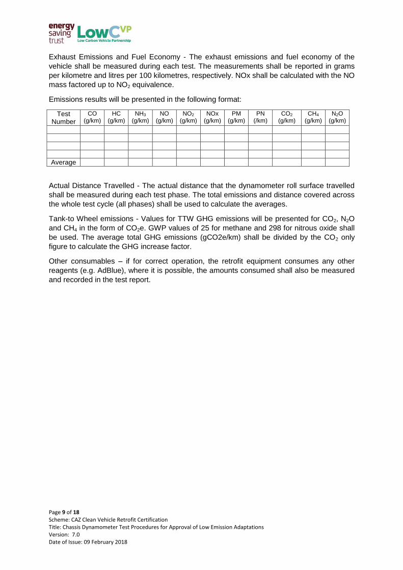
Exhaust Emissions and Fuel Economy - The exhaust emissions and fuel economy of the
vehicle shall be measured during each test. The measurements shall be reported in grams
per kilometre and litres per 100 kilometres, respectively. NOx shall be calculated with the NO
mass factored up to NO2 equivalence.
Emissions results will be presented in the following format:
Test Number
CO (g/km)
HC (g/km)
NH3 (g/km)
NO (g/km)
NO2 (g/km)
NOx (g/km)
PM (g/km)
PN (/km)
CO2 (g/km)
CH4 (g/km)
N2O (g/km)
Average
Actual Distance Travelled - The actual distance that the dynamometer roll surface travelled
shall be measured during each test phase. The total emissions and distance covered across
the whole test cycle (all phases) shall be used to calculate the averages.
Tank-to Wheel emissions - Values for TTW GHG emissions will be presented for CO2, N2O
and CH4 in the form of CO2e. GWP values of 25 for methane and 298 for nitrous oxide shall
be used. The average total GHG emissions (gCO2e/km) shall be divided by the CO2 only
figure to calculate the GHG increase factor.
Other consumables – if for correct operation, the retrofit equipment consumes any other
reagents (e.g. AdBlue), where it is possible, the amounts consumed shall also be measured
and recorded in the test report.
Page 10 of 18 Scheme: CAZ Clean Vehicle Retrofit Certification Title: Chassis Dynamometer Test Procedures for Approval of Low Emission Adaptations Version: 7.0 Date of Issue: 09 February 2018
Annex 1. Detailed test conditions; buses
Vehicle Loading
Buses shall be tested at kerb weight plus driver weight (75kg) and either:
a) One quarter of the specified total passenger load using a weight of 68 kg per
passenger, or
b) One half of the specified seated passenger load using a weight of 68 kg per
passenger, whichever is judged by the technical service (and agreed by LowCVP) to
be the worst case for effective performance of the retrofit system.
The kerb weight of the vehicle shall be determined prior to test by the technical service
carrying out the test.
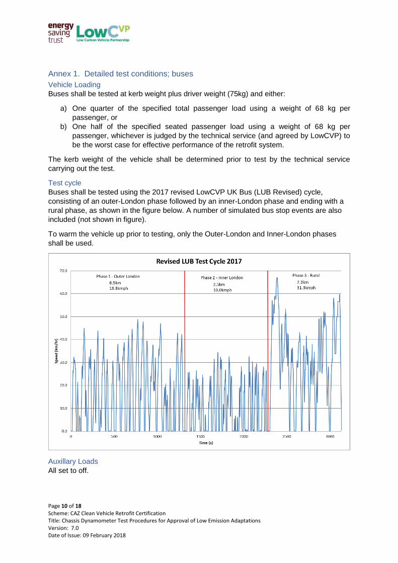
Test cycle
Buses shall be tested using the 2017 revised LowCVP UK Bus (LUB Revised) cycle,
consisting of an outer-London phase followed by an inner-London phase and ending with a
rural phase, as shown in the figure below. A number of simulated bus stop events are also
included (not shown in figure).
To warm the vehicle up prior to testing, only the Outer-London and Inner-London phases
shall be used.
Auxillary Loads
All set to off.
Page 11 of 18 Scheme: CAZ Clean Vehicle Retrofit Certification Title: Chassis Dynamometer Test Procedures for Approval of Low Emission Adaptations Version: 7.0 Date of Issue: 09 February 2018
Annex 2. Detailed test conditions; coaches
Vehicle Loading
Coaches shall be tested at kerb weight plus driver weight (75kg) and either:
a) 100% of the specified total passenger load using a weight of 68 kg per passenger, or
b) 50% of the specified maximum payload capacity, whichever is judged by the
technical service (and agreed by LowCVP) to be the worst case for effective
performance of the retrofit system.
The kerb weight of the vehicle shall be determined prior to test by the technical service
carrying out the test. The technical service shall
Test cycle
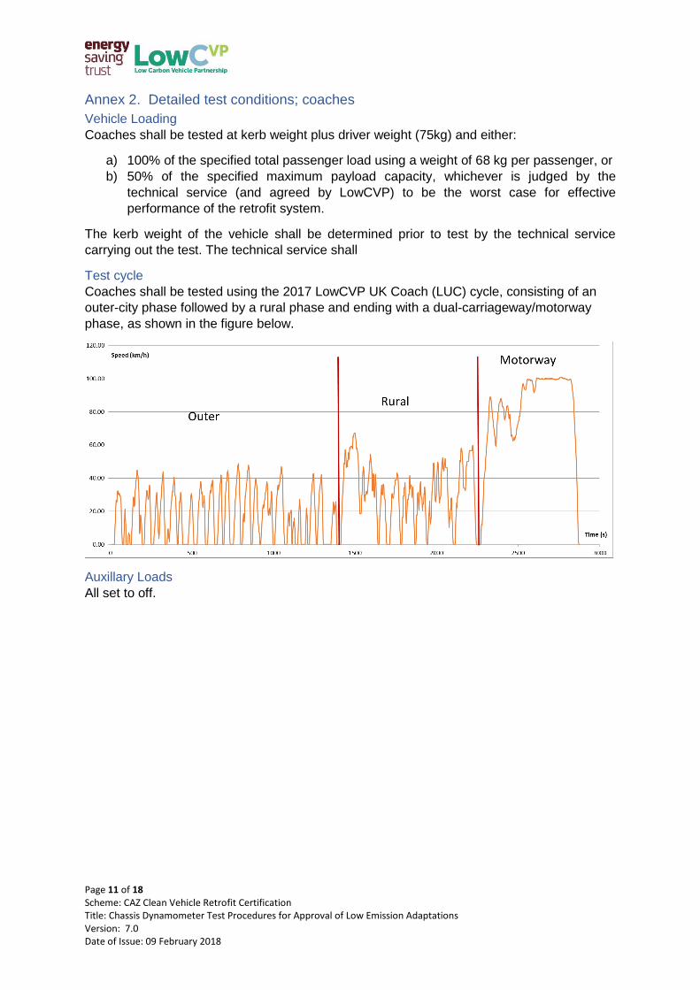
Coaches shall be tested using the 2017 LowCVP UK Coach (LUC) cycle, consisting of an
outer-city phase followed by a rural phase and ending with a dual-carriageway/motorway
phase, as shown in the figure below.
Auxillary Loads
All set to off.
Page 12 of 18 Scheme: CAZ Clean Vehicle Retrofit Certification Title: Chassis Dynamometer Test Procedures for Approval of Low Emission Adaptations Version: 7.0 Date of Issue: 09 February 2018
Annex 3. Detailed test conditions; HGVs (N2 & N3)
Vehicle Loading
Trucks shall be tested at kerb weight plus driver weight (75kg) and either:
a) 50-60% of the specified maximum payload capacity, or, in cases where this is not
technically possible;
b) Loading up to a vehicle weight equivalent to at least 90% of the specified maximum
load of the dynamometer
The kerb weight of the vehicle shall be determined prior to test by the technical service
carrying out the test.
Test cycle
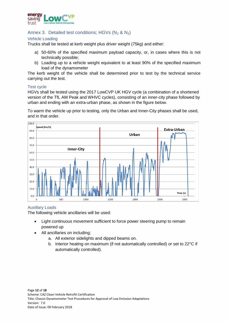
HGVs shall be tested using the 2017 LowCVP UK HGV cycle (a combination of a shortened
version of the TfL AM Peak and WHVC cycles), consisting of an inner-city phase followed by
urban and ending with an extra-urban phase, as shown in the figure below.
To warm the vehicle up prior to testing, only the Urban and Inner-City phases shall be used,
and in that order.
Auxillary Loads
The following vehicle ancillaries will be used:
Light continuous movement sufficient to force power steering pump to remain
powered up
All ancillaries on including;
a. All exterior sidelights and dipped beams on.
b. Interior heating on maximum (if not automatically controlled) or set to 22°C if
automatically controlled).
Page 13 of 18 Scheme: CAZ Clean Vehicle Retrofit Certification Title: Chassis Dynamometer Test Procedures for Approval of Low Emission Adaptations Version: 7.0 Date of Issue: 09 February 2018
Annex 4. Detailed test conditions; Vans (N1)
Vehicle Loading
Vans shall be tested at kerb weight plus driver weight (75kg) and 50-60% of the specified
maximum payload capacity.
The kerb weight of the vehicle shall be determined prior to test by the technical service
carrying out the test.
Test cycle
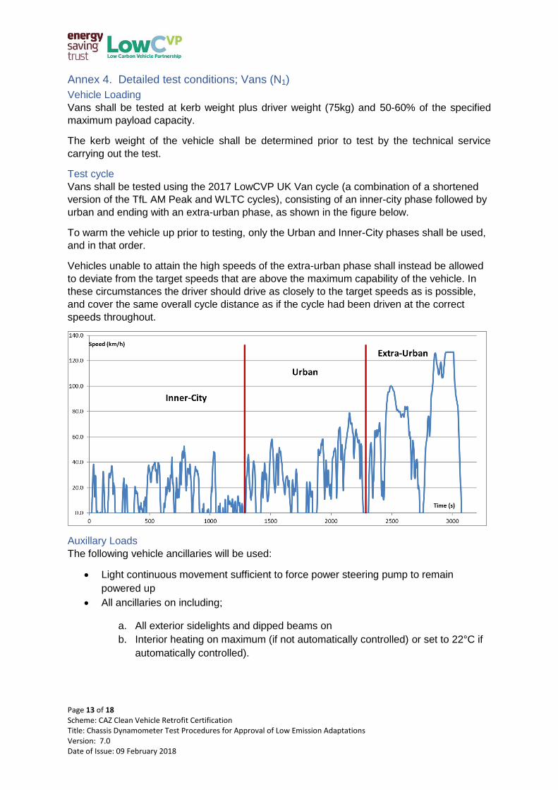
Vans shall be tested using the 2017 LowCVP UK Van cycle (a combination of a shortened
version of the TfL AM Peak and WLTC cycles), consisting of an inner-city phase followed by
urban and ending with an extra-urban phase, as shown in the figure below.
To warm the vehicle up prior to testing, only the Urban and Inner-City phases shall be used,
and in that order.
Vehicles unable to attain the high speeds of the extra-urban phase shall instead be allowed
to deviate from the target speeds that are above the maximum capability of the vehicle. In
these circumstances the driver should drive as closely to the target speeds as is possible,
and cover the same overall cycle distance as if the cycle had been driven at the correct
speeds throughout.
Auxillary Loads
The following vehicle ancillaries will be used:
Light continuous movement sufficient to force power steering pump to remain
powered up
All ancillaries on including;
a. All exterior sidelights and dipped beams on
b. Interior heating on maximum (if not automatically controlled) or set to 22°C if
automatically controlled).
Page 14 of 18 Scheme: CAZ Clean Vehicle Retrofit Certification Title: Chassis Dynamometer Test Procedures for Approval of Low Emission Adaptations Version: 7.0 Date of Issue: 09 February 2018
Annex 5. Detailed test conditions; Taxis (Black Cabs) (M1, GVW over 2t)
There are two potential test cycles for Taxis (Black Cabs), the PCO-CENEX London Taxi
Drive Cycle or the WLTC. TfL Taxi & PH will require specific further evaluation however
Taxi CVRAS will accept TfL Taxi & PH (PCO) approvals.
PCO-CENEX London Taxi Drive Cycle
Vehicle Loading
Dynamometer inertia shall be set to kerb weight (no driver, full fluids) plus 150kg to
represent a driver and single passenger. The inertia will be set to within 10kg of defined
vehicle mass with no maximum defined.
Test cycle
Tests shall be conducted to the general procedures outlined in European Union Directive
70/220/EC, as amended by the latest version, with the following exceptions:
The test is a ‘hot-start’ drive cycle which requires a warm-up period of 15 minutes. The
vehicle shall be driven at 50km/h for 5 minutes followed by 5 minutes at 40 km/h and 5
minutes at 30km/h.
Following this warm-up the vehicle shall be allowed to idle for a maximum of 30 seconds
before starting the first phase of the drive cycle.
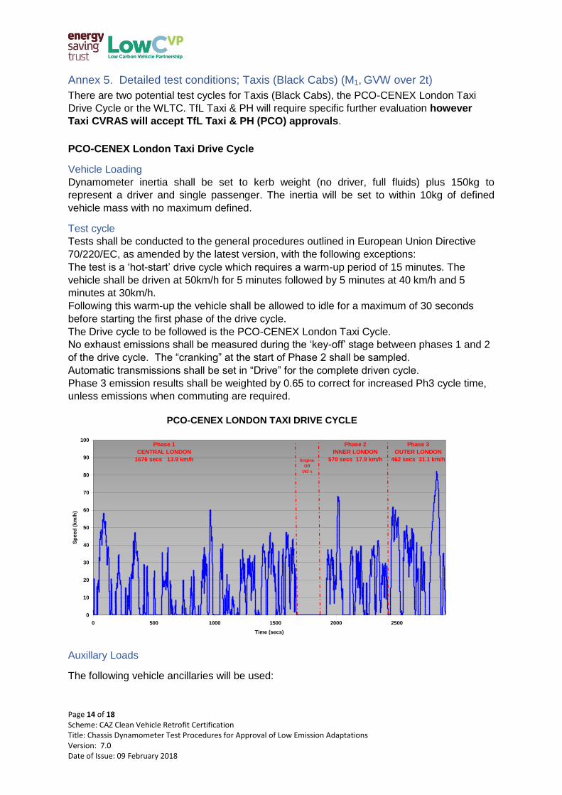
The Drive cycle to be followed is the PCO-CENEX London Taxi Cycle.
No exhaust emissions shall be measured during the ‘key-off’ stage between phases 1 and 2
of the drive cycle. The “cranking” at the start of Phase 2 shall be sampled.
Automatic transmissions shall be set in “Drive” for the complete driven cycle.
Phase 3 emission results shall be weighted by 0.65 to correct for increased Ph3 cycle time,
unless emissions when commuting are required.
Auxillary Loads
The following vehicle ancillaries will be used:
PCO-CENEX LONDON TAXI DRIVE CYCLE
0
10
20
30
40
50
60
70
80
90
100
0 500 1000 1500 2000 2500
Time (secs)
Sp
eed
(k
m/h
)
Phase 1
CENTRAL LONDON
1676 secs 13.9 km/h Engine
Off
192 s
Phase 2
INNER LONDON
570 secs 17.9 km/h
Phase 3
OUTER LONDON
462 secs 31.1 km/h
Page 15 of 18 Scheme: CAZ Clean Vehicle Retrofit Certification Title: Chassis Dynamometer Test Procedures for Approval of Low Emission Adaptations Version: 7.0 Date of Issue: 09 February 2018
Ancillaries shall be switched off with the exception of the Taxi Meter and DRL
(daytime running lights), where fitted
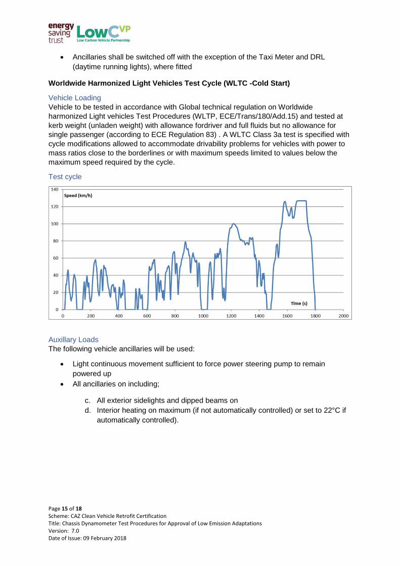
Worldwide Harmonized Light Vehicles Test Cycle (WLTC -Cold Start)
Vehicle Loading
Vehicle to be tested in accordance with Global technical regulation on Worldwide
harmonized Light vehicles Test Procedures (WLTP, ECE/Trans/180/Add.15) and tested at
kerb weight (unladen weight) with allowance fordriver and full fluids but no allowance for
single passenger (according to ECE Regulation 83) . A WLTC Class 3a test is specified with
cycle modifications allowed to accommodate drivability problems for vehicles with power to
mass ratios close to the borderlines or with maximum speeds limited to values below the
maximum speed required by the cycle.
Test cycle
Auxillary Loads
The following vehicle ancillaries will be used:
Light continuous movement sufficient to force power steering pump to remain
powered up
All ancillaries on including;
c. All exterior sidelights and dipped beams on
d. Interior heating on maximum (if not automatically controlled) or set to 22°C if
automatically controlled).
Page 16 of 18 Scheme: CAZ Clean Vehicle Retrofit Certification Title: Chassis Dynamometer Test Procedures for Approval of Low Emission Adaptations Version: 7.0 Date of Issue: 09 February 2018
Annex 6. Emission limits permitted from the vehicle fitted with the low emission
adaptation
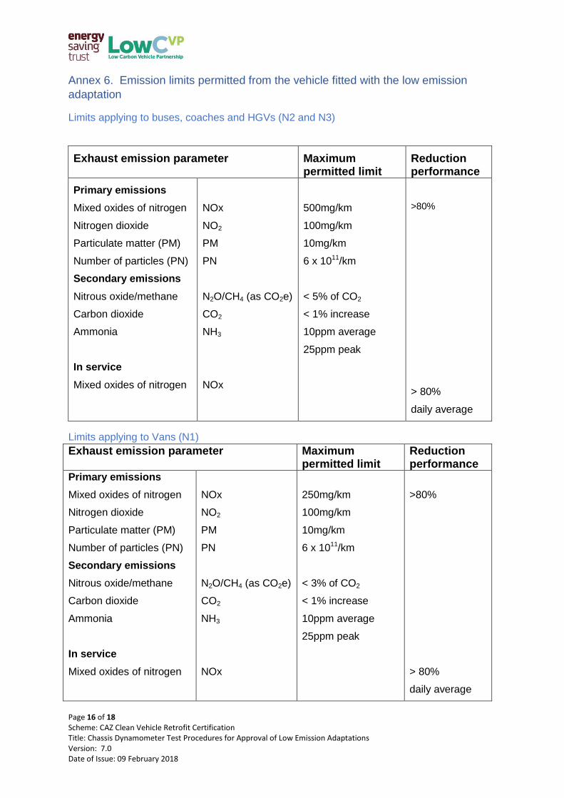
Limits applying to buses, coaches and HGVs (N2 and N3)
Exhaust emission parameter Maximum permitted limit
Reduction performance
Primary emissions
Mixed oxides of nitrogen
Nitrogen dioxide
Particulate matter (PM)
Number of particles (PN)
Secondary emissions
Nitrous oxide/methane
Carbon dioxide
Ammonia
In service
Mixed oxides of nitrogen
NOx
NO2
PM
PN
N2O/CH4 (as CO2e)
CO2
NH3
NOx
500mg/km
100mg/km
10mg/km
6 x 10¹¹/km
< 5% of CO2
< 1% increase
10ppm average
25ppm peak
>80%
> 80%
daily average
Limits applying to Vans (N1)
Exhaust emission parameter Maximum permitted limit
Reduction performance
Primary emissions
Mixed oxides of nitrogen
Nitrogen dioxide
Particulate matter (PM)
Number of particles (PN)
Secondary emissions
Nitrous oxide/methane
Carbon dioxide
Ammonia
In service
Mixed oxides of nitrogen
NOx
NO2
PM
PN
N2O/CH4 (as CO2e)
CO2
NH3
NOx
250mg/km
100mg/km
10mg/km
6 x 10¹¹/km
< 3% of CO2
< 1% increase
10ppm average
25ppm peak
>80%
> 80%
daily average
Page 17 of 18 Scheme: CAZ Clean Vehicle Retrofit Certification Title: Chassis Dynamometer Test Procedures for Approval of Low Emission Adaptations Version: 7.0 Date of Issue: 09 February 2018
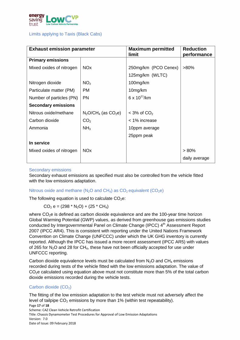
Limits applying to Taxis (Black Cabs)
Exhaust emission parameter Maximum permitted limit
Reduction performance
Primary emissions
Mixed oxides of nitrogen
Nitrogen dioxide
Particulate matter (PM)
Number of particles (PN)
Secondary emissions
Nitrous oxide/methane
Carbon dioxide
Ammonia
In service
Mixed oxides of nitrogen
NOx
NO2
PM
PN
N2O/CH4 (as CO2e)
CO2
NH3
NOx
250mg/km (PCO Cenex)
125mg/km (WLTC)
100mg/km
10mg/km
6 x 10¹¹/km
< 3% of CO2
< 1% increase
10ppm average
25ppm peak
>80%
> 80%
daily average
Secondary emissions
Secondary exhaust emissions as specified must also be controlled from the vehicle fitted
with the low emissions adaptation.
Nitrous oxide and methane (N2O and CH4) as CO2 equivalent (CO2e)
The following equation is used to calculate CO2e:
CO2 e = (298 * N2O) + (25 * CH4)
where CO2e is defined as carbon dioxide equivalence and are the 100-year time horizon
Global Warming Potential (GWP) values, as derived from greenhouse gas emissions studies
conducted by Intergovernmental Panel on Climate Change (IPCC) 4th Assessment Report
2007 (IPCC AR4). This is consistent with reporting under the United Nations Framework
Convention on Climate Change (UNFCCC) under which the UK GHG inventory is currently
reported. Although the IPCC has issued a more recent assessment (IPCC AR5) with values
of 265 for N2O and 28 for CH4, these have not been officially accepted for use under
UNFCCC reporting.
Carbon dioxide equivalence levels must be calculated from N2O and CH4 emissions
recorded during tests of the vehicle fitted with the low emissions adaptation. The value of
CO2e calculated using equation above must not constitute more than 5% of the total carbon
dioxide emissions recorded during the vehicle tests.
Carbon dioxide (CO2)
The fitting of the low emission adaptation to the test vehicle must not adversely affect the
level of tailpipe CO2 emissions by more than 1% (within test repeatability).
Page 18 of 18 Scheme: CAZ Clean Vehicle Retrofit Certification Title: Chassis Dynamometer Test Procedures for Approval of Low Emission Adaptations Version: 7.0 Date of Issue: 09 February 2018
Ammonia (NH3)
Ammonia tailpipe emissions of the vehicle fitted with the low emissions adaptation are
limited to a mean concentration of 10 parts per million (ppm) and a peak value of 25 ppm
during the testing.
Recommended