University of Southern Queensland
Faculty of Sciences
Cloud-based Network Simulator for Next Generation
Wireless Technology (WiMAX and LTE)
A thesis submitted by
Gerson Bacor
in fulfilment of the requirements of
Master of Information Technology
Submitted: October, 2011
Abstract
In today’s modern world, the high demand for wireless data has brought about a
continued surge in global mobile data traffic. It is reported that several countries
experience extremely high growth rates for wireless data. With this high demand, the
wireless telecom industry has invested their time, money, and effort to define a new air
interface for broadband wireless network which provides high mobility internet service
and increases system capacity.
Among the many emerging technologies, WiMAX which is defined by IEEE (Institute
of Electrical and Electronics Engineers) and LTE which is defined by 3GPP (3rd Gen-
eration Partnership Project) are the only technologies that provides high peak data
rates, mobility service, and high spectral efficiency. These technologies are considered
the fourth generation (4G) cellular wireless mobile network. Both are widely used in
research and development.
Doing research and development on the next generation wireless technologies such as
LTE and WiMAX pose many challenges. Deployments are expensive and particularly
difficult to emulate in real hardware making simulation models very important during
research and development. One of the biggest challenges for the network simulator is
the amount of processing power required to simulate real world performance.
A prototype of a cloud-based network simulator that involves ns-3 and NetML shall be
implemented that can support both WiMAX and LTE network simulation and perform
test scenarios such as ping test and throughput measurement.

Acknowledgments
I would like to take this opportunity to thank my supervisor, Professor Ron Addie for
his guidance and constant support on my thesis. I am grateful and honored for the
opportunity to work with him.
Furthermore, I would like to thank my family and friends, especially my girlfriend for
her support throughout the project.
Gerson Bacor
University of Southern Queensland
October 2011
Contents
Abstract i
Acknowledgments ii
List of Figures ix
List of Tables xiii
Acronyms & Abbreviations xiv
Chapter 1 Introduction 1
1.1 Background . . . . . . . . . . . . . . . . . . . . . . . . . . . . . . . . . . 1
1.2 Research Objective . . . . . . . . . . . . . . . . . . . . . . . . . . . . . . 2
Chapter 2 Literature Review 3
2.1 Network Simulation . . . . . . . . . . . . . . . . . . . . . . . . . . . . . 3
2.1.1 Open Source Network Simulator . . . . . . . . . . . . . . . . . . 4
2.1.2 Commercial Network Simulator . . . . . . . . . . . . . . . . . . . 5

CONTENTS iv
2.2 Existing Literatures . . . . . . . . . . . . . . . . . . . . . . . . . . . . . 6
2.2.1 Related Work in WiMAX . . . . . . . . . . . . . . . . . . . . . . 6
2.2.2 Related Work in LTE . . . . . . . . . . . . . . . . . . . . . . . . 10
Chapter 3 WiMAX Protocol Concept and Details 12
3.1 WiMAX Overview . . . . . . . . . . . . . . . . . . . . . . . . . . . . . . 12
3.2 Evolution of WiMAX . . . . . . . . . . . . . . . . . . . . . . . . . . . . 14
3.2.1 IEEE 802.16 Standards . . . . . . . . . . . . . . . . . . . . . . . 14
3.2.2 Fixed WiMAX . . . . . . . . . . . . . . . . . . . . . . . . . . . . 14
3.2.3 Mobile WiMAX 1 . . . . . . . . . . . . . . . . . . . . . . . . . . 15
3.2.4 Fixed and Mobile WiMAX 1 . . . . . . . . . . . . . . . . . . . . 15
3.2.5 Mobile WiMAX 2 . . . . . . . . . . . . . . . . . . . . . . . . . . 15
3.3 WiMAX Architecture . . . . . . . . . . . . . . . . . . . . . . . . . . . . 16
3.3.1 WiMAX Network . . . . . . . . . . . . . . . . . . . . . . . . . . . 16
3.4 Physical Layer . . . . . . . . . . . . . . . . . . . . . . . . . . . . . . . . 17
3.4.1 PHY Layer . . . . . . . . . . . . . . . . . . . . . . . . . . . . . . 17
3.4.2 OFDM and OFDMA System . . . . . . . . . . . . . . . . . . . . 17
3.4.3 Time and Frequency Division Duplexing . . . . . . . . . . . . . . 18
3.4.4 Modulation and Coding . . . . . . . . . . . . . . . . . . . . . . . 19
3.5 Medium Access Control Layer . . . . . . . . . . . . . . . . . . . . . . . . 20
3.5.1 MAC Layer . . . . . . . . . . . . . . . . . . . . . . . . . . . . . . 20
CONTENTS v
3.5.2 Service-Specific Convergence Sublayer . . . . . . . . . . . . . . . 21
3.5.3 Common Part Sublayer . . . . . . . . . . . . . . . . . . . . . . . 22
3.5.4 Network Entry Procedure . . . . . . . . . . . . . . . . . . . . . . 23
3.5.5 Uplink Scheduling Services . . . . . . . . . . . . . . . . . . . . . 26
3.6 Convergence of IEEE 802.16 MAC and IP Layer . . . . . . . . . . . . . 27
3.6.1 IP over IEEE 802.16 . . . . . . . . . . . . . . . . . . . . . . . . . 27
3.6.2 IEEE 802.16 Reliable Transmission . . . . . . . . . . . . . . . . . 28
3.6.2.1 ARQ . . . . . . . . . . . . . . . . . . . . . . . . . . . . 29
3.6.2.2 HARQ . . . . . . . . . . . . . . . . . . . . . . . . . . . 29
3.7 WiMAX Capacity . . . . . . . . . . . . . . . . . . . . . . . . . . . . . . 29
3.7.1 Channel Capacity . . . . . . . . . . . . . . . . . . . . . . . . . . 29
3.7.2 PHY Throughput . . . . . . . . . . . . . . . . . . . . . . . . . . 31
Chapter 4 LTE Protocol Concept and Details 34
4.1 Overall Architecture . . . . . . . . . . . . . . . . . . . . . . . . . . . . . 35
4.2 Functional Split . . . . . . . . . . . . . . . . . . . . . . . . . . . . . . . . 36
4.3 Radio Protocol architecture . . . . . . . . . . . . . . . . . . . . . . . . . 36
4.4 Physical Layer for E-UTRA . . . . . . . . . . . . . . . . . . . . . . . . . 38
4.4.1 OFDM . . . . . . . . . . . . . . . . . . . . . . . . . . . . . . . . 38
4.4.2 OFDMA . . . . . . . . . . . . . . . . . . . . . . . . . . . . . . . . 39
4.4.3 Single Carrier-Frequency Division Multiple Access (SC-FDMA) . 39
CONTENTS vi
4.4.4 MIMO . . . . . . . . . . . . . . . . . . . . . . . . . . . . . . . . . 40
4.5 LTE Layer 2 . . . . . . . . . . . . . . . . . . . . . . . . . . . . . . . . . 40
4.5.1 Channel structure . . . . . . . . . . . . . . . . . . . . . . . . . . 41
4.5.2 Uplink mapping of Transport Channels to Logical Channels . . . 42
4.5.3 Downlink mapping of Transport Channels to Logical Channels . 43
4.5.4 Data Transmission . . . . . . . . . . . . . . . . . . . . . . . . . . 43
4.6 Radio Link Control . . . . . . . . . . . . . . . . . . . . . . . . . . . . . . 44
4.7 Packet Data Convergence Protocol . . . . . . . . . . . . . . . . . . . . . 45
4.7.1 PDCP structure . . . . . . . . . . . . . . . . . . . . . . . . . . . 45
Chapter 5 WiMAX and LTE Comparison 47
5.1 WiMAX and LTE Technical Differences . . . . . . . . . . . . . . . . . . 48
5.2 WiMAX Deployments . . . . . . . . . . . . . . . . . . . . . . . . . . . . 49
5.3 LTE Deployments . . . . . . . . . . . . . . . . . . . . . . . . . . . . . . 49
Chapter 6 Cloud-based Simulator Design and Implementation 51
6.1 Features . . . . . . . . . . . . . . . . . . . . . . . . . . . . . . . . . . . . 52
6.2 Design . . . . . . . . . . . . . . . . . . . . . . . . . . . . . . . . . . . . . 53
6.3 Graphical User Interface (GUI) . . . . . . . . . . . . . . . . . . . . . . . 55
6.4 Information Model . . . . . . . . . . . . . . . . . . . . . . . . . . . . . . 55
6.4.1 NetML XML . . . . . . . . . . . . . . . . . . . . . . . . . . . . . 56

CONTENTS vii
6.5 Implementation . . . . . . . . . . . . . . . . . . . . . . . . . . . . . . . . 59
6.6 Code Generator . . . . . . . . . . . . . . . . . . . . . . . . . . . . . . . . 61
6.7 Simulator . . . . . . . . . . . . . . . . . . . . . . . . . . . . . . . . . . . 62
6.7.1 Ns-3 WiMAX Model . . . . . . . . . . . . . . . . . . . . . . . . . 62
6.7.2 Ns-3 LTE Model . . . . . . . . . . . . . . . . . . . . . . . . . . . 63
6.7.3 Running the Simulator . . . . . . . . . . . . . . . . . . . . . . . . 64
6.8 Network Simulator Output File . . . . . . . . . . . . . . . . . . . . . . . 65
6.9 Limitations . . . . . . . . . . . . . . . . . . . . . . . . . . . . . . . . . . 66
Chapter 7 Simulation and Results 67
7.1 WiMAX Ping Test Scenario . . . . . . . . . . . . . . . . . . . . . . . . . 67
7.1.1 Simple Network Design . . . . . . . . . . . . . . . . . . . . . . . 67
7.1.2 Simulation Results . . . . . . . . . . . . . . . . . . . . . . . . . . 68
7.2 WiMAX Multiple Subscriber Stations Throughput Test Scenario . . . . 68
7.2.1 NetML Network Design . . . . . . . . . . . . . . . . . . . . . . . 68
7.2.2 Simulation Results . . . . . . . . . . . . . . . . . . . . . . . . . . 69
7.3 LTE Simulation . . . . . . . . . . . . . . . . . . . . . . . . . . . . . . . . 71
7.3.1 NetML Network Design . . . . . . . . . . . . . . . . . . . . . . . 71
7.3.2 Simulation Results . . . . . . . . . . . . . . . . . . . . . . . . . . 71
Chapter 8 Conclusion and Future Work 73

CONTENTS viii
Bibliography 75
Appendix A Source Code 79

List of Figures
2.1 Downlink throughput . . . . . . . . . . . . . . . . . . . . . . . . . . . . 7
2.2 Uplink throughput . . . . . . . . . . . . . . . . . . . . . . . . . . . . . . 7
2.3 System Model Implementation in OPNET . . . . . . . . . . . . . . . . . 8
2.4 MAC Layer throughput . . . . . . . . . . . . . . . . . . . . . . . . . . . 9
2.5 Data throughput with multiple subscriber stations (SS) . . . . . . . . . 9
2.6 Simulation based on EVA channel . . . . . . . . . . . . . . . . . . . . . 10
3.1 WiMAX Point of Presence [19] . . . . . . . . . . . . . . . . . . . . . . . 13
3.2 WiMAX Network Management Reference Model, from [24] . . . . . . . 16
3.3 Frequency-Time Representation of OFDM Signal . . . . . . . . . . . . . 17
3.4 Insertion of Cyclic Prefix, from [26] . . . . . . . . . . . . . . . . . . . . . 18
3.5 Example of OFDMA Frame in TDD, from [24] . . . . . . . . . . . . . . 19
3.6 MAC Architecture, from [24] . . . . . . . . . . . . . . . . . . . . . . . . 20
3.7 MAC Service-Specific Convergence Sublayer . . . . . . . . . . . . . . . . 21
3.8 MAC Common Part Sublyer . . . . . . . . . . . . . . . . . . . . . . . . . 22
LIST OF FIGURES x
3.9 MAC Protocol Data Unit Structure . . . . . . . . . . . . . . . . . . . . 23
3.10 Network Entry Procedure [21] . . . . . . . . . . . . . . . . . . . . . . . . 24
3.11 WiMAX Quality of Service, from [27] . . . . . . . . . . . . . . . . . . . 27
3.12 IP over IEEE 802.16 . . . . . . . . . . . . . . . . . . . . . . . . . . . . . 28
3.13 TDD Frame Structure . . . . . . . . . . . . . . . . . . . . . . . . . . . . 31
3.14 PUSC Slot Structure . . . . . . . . . . . . . . . . . . . . . . . . . . . . . 32
4.1 Overall Architecture, from [37] . . . . . . . . . . . . . . . . . . . . . . . 35
4.2 Functional Split between E-UTRAN and EPC, from [37] . . . . . . . . . 36
4.3 User plane protocol stack, from [37] . . . . . . . . . . . . . . . . . . . . 37
4.4 Control-plane protocol stack, from [37] . . . . . . . . . . . . . . . . . . . 37
4.5 Radio interface protocol architecture around the physical layer, from [37] 38
4.6 Comparison of how OFDMA and SC-FDMA transmit a sequence of
QPSK data symbols, from [40] . . . . . . . . . . . . . . . . . . . . . . . 39
4.7 LTE Downlink and Uplink data rates, from [40] . . . . . . . . . . . . . . 40
4.8 MAC structure overview in UE side, from [41] . . . . . . . . . . . . . . . 41
4.9 Mapping of Uplink Transport channels to Logical channels, from [41] . . 43
4.10 Mapping of Downlink Transport channels to Logical channels, from [41] 43
4.11 LTE Downlink data flow, from [42] . . . . . . . . . . . . . . . . . . . . . 44
4.12 Overview model of the RLC sub layer . . . . . . . . . . . . . . . . . . . 45
4.13 PDCP layer functional view, from [38]. . . . . . . . . . . . . . . . . . . . 46

LIST OF FIGURES xi
5.1 WiMAX and LTE Roadmap, from [39] . . . . . . . . . . . . . . . . . . . 48
5.2 WiMAX and LTE Technical Differences [39] . . . . . . . . . . . . . . . . 49
5.3 WiMAX Deployment Map (www.wimaxmaps.org) . . . . . . . . . . . . 50
5.4 LTE Deployment Map (www.ltemaps.org) . . . . . . . . . . . . . . . . . 50
6.1 Block diagram . . . . . . . . . . . . . . . . . . . . . . . . . . . . . . . . 53
6.2 Overall Block Diagram . . . . . . . . . . . . . . . . . . . . . . . . . . . . 54
6.3 NetML User Interface . . . . . . . . . . . . . . . . . . . . . . . . . . . . 55
6.4 A simple NetML WiMAX Network . . . . . . . . . . . . . . . . . . . . . 56
6.5 bsNode element in NetML . . . . . . . . . . . . . . . . . . . . . . . . . . 57
6.6 ssNode element in NetML . . . . . . . . . . . . . . . . . . . . . . . . . . 57
6.7 link element in NetML . . . . . . . . . . . . . . . . . . . . . . . . . . . . 58
6.8 trafficStreams and simulation element in NetML . . . . . . . . . . . . . 58
6.9 XSL Script code snippet . . . . . . . . . . . . . . . . . . . . . . . . . . . 60
6.10 Creation of BS and SS nodes . . . . . . . . . . . . . . . . . . . . . . . . 61
6.11 Generation of simulation script . . . . . . . . . . . . . . . . . . . . . . . 62
6.12 Ns-3 WiMAX Design, from [15] . . . . . . . . . . . . . . . . . . . . . . . 63
6.13 Ns-3 LTE Design, from [16] . . . . . . . . . . . . . . . . . . . . . . . . . 64
6.14 Running the ns-3 script . . . . . . . . . . . . . . . . . . . . . . . . . . . 65
6.15 Python srcipt for parsing the ns-3 output file . . . . . . . . . . . . . . . 65
6.16 Simulation Output . . . . . . . . . . . . . . . . . . . . . . . . . . . . . . 66
LIST OF FIGURES xii
7.1 Simple WiMAX network design . . . . . . . . . . . . . . . . . . . . . . . 67
7.2 Configuration of Ping test scenario . . . . . . . . . . . . . . . . . . . . . 68
7.3 Ping test output . . . . . . . . . . . . . . . . . . . . . . . . . . . . . . . 68
7.4 WiMAX Network Design with multiple subscriber stations . . . . . . . . 69
7.5 Throughput Results . . . . . . . . . . . . . . . . . . . . . . . . . . . . . 70
7.6 LTE with multiple UEs network design . . . . . . . . . . . . . . . . . . . 71
7.7 LTE throughput results . . . . . . . . . . . . . . . . . . . . . . . . . . . 72
List of Tables
2.1 Throughput using multiple subscriber stations . . . . . . . . . . . . . . 8
2.2 LTE vs WiMAX response time . . . . . . . . . . . . . . . . . . . . . . . 11
2.3 LTE vs WiMAX throughput measurement . . . . . . . . . . . . . . . . . 11
3.1 WiMAX Deployment by frequency . . . . . . . . . . . . . . . . . . . . . 14
3.2 Supported Coding and Modulation [26] . . . . . . . . . . . . . . . . . . 19
3.3 SNR Values [24] . . . . . . . . . . . . . . . . . . . . . . . . . . . . . . . 30
4.1 Transport channels used by MAC, from [41] . . . . . . . . . . . . . . . . 42
4.2 Logical channels provided by MAC, from [41] . . . . . . . . . . . . . . . 42
6.1 Supported Features . . . . . . . . . . . . . . . . . . . . . . . . . . . . . . 53
6.2 Limitations . . . . . . . . . . . . . . . . . . . . . . . . . . . . . . . . . . 66
7.1 Throughput and no. of dropped packets for 8 subscriber stations . . . . 70
Acronyms & Abbreviations
3GPP 3rd Generation Partnership Project
AMC Advance Modulation Coding
APN Access Point Name
ARQ Automatic Repeat Query
AS Access Stratum
ASN Access Service Network
ATM Asynchronous Transfer Mode
BCCH Broadcast Control Channel
BCH Broadcast Channel
BS Base Station
BWA Broadband Wireless Access
CCCH Common Control Channel
CID Connection Identifier
CDMA Code Division Multiple Access
CP Cyclic Prefix
CPS Common Part Sublayer
CQI Channel Quality Indicator
CRC Cyclic Redundancy Check
CS Convergence Sublayer
CSN Connectivity Service Network
DCCH Dedicated Control Channel
DCD Downlink Channel Descriptor
DHCP Dynamic Host Configuration Protocol
DL Downlink

LIST OF TABLES xv
DTCH Dedicated Traffic Channel
E-UTRA Evolved UMTS Terrestrial Radio Access
E-UTRAN Evolved Universal Terrestrial Radio Access Network Node
ECM EPS Connection Management
EDGE Enhanced Data rates for GSM Evolution
eNB E-UTRAN NodeB
EPC Evolved Packet Core
EPS Evolved Packet System
ETSI European Telecommunications Standards Institute
FDD Frequency Division Duplexing
FEC Forward Error Correction
FFT Fast Fourier Transform
FUSC Fully Used Sub-Carrier
GMH Generic MAC Header
GPRS General Packet Radio Service
GSM Global System for Mobile communication
HARQ Hybrid-ARQ
HCS Header Check Sequence
ICMP Internet Control Message Protocol
IEEE Institute of Electrical and Electronics Engineers
IETF Internet Engineering Task Force
IMT International Mobile Telecommunications
IP Internet Protocol
IPv4 Internet Protocol version 4
IPv6 Internet Protocol version 6
ISI Inter-Symbol Interference
ITU International Telecommunication Union
LAN Local Area Network
LOS Line-of-Sight
LTE Long Term Evolution
MAC Medium Access Control
MAN Metropolitan Area Network
MIMO Multiple Input Multiple Output
LIST OF TABLES xvi
MME Mobility Management Entity
MS Mobile Station
MTU Maximum Transmission Unit
NLOS Non-Line-of-Sight
NWG Network Working Group
OFDM Orthogonal Frequency-Division Multiplexing
OFDMA Orthogonal Frequency-Division Multiple Access
OSI Open Systems Interconnection
PBCH Physical Broadcast Channel
PCCH Paging Control Channel
PCFICH Physical Control Format Indicator Channel
PCH Paging Channel
PDCCH Physical Downlink Control Channel
PDCP Packet Data Convergence Protocol
PDN Packet Data Network
PDSCH Physical Downlink Shared Channel
PDU Protocol Data Unit
PHICH Physical Hybrid ARQ Indicator Channel
PHY Physical layer
PMCH Physical Multicast Channel
PMP Point-to-Multipoint
PRACH Physical Random Access Channel
PUCCH Physical Uplink Control Channel
PUSC Partially Used Sub-Carrier
PUSCH Physical Uplink Shared Channel
QAM Quadrature Amplitude Modulation
QoS Quality of Service
QPSK Quadrature Phase-Shift Keying
RACH Random Access Channel
RB Radio Bearer
RLC Radio Link Control
ROHC Robust Header Compression
RRC Radio Resource Control
LIST OF TABLES xvii
RTT Round Trip Time
S-GW Serving Gateway
S-OFDMA Scalable Orthogonal Frequency-Division Multiple Access
SAP Service Access Points
SC-FDMA Single-Carrier Frequency Division Multiple Access
SCH Synchronization Channel
SDU Service Data Unit
SGSN Serving GPRS Support Node
SNR Signal-to-noise ratio
SS Subscriber Station
SSF Scalable Simulation Framework Net
TDD Time Division Duplexing
TFTP Trivial File Transfer Protocol
UCD Uplink Channel Descriptor
UDP User Datagram Protocol
UE User Equipment
UL Uplink
UMTS Universal Mobile Telecommunication System
Chapter 1
Introduction
1.1 Background
A network simulation is a technique where a program predicts the behavior of a network
without an actual network device being present. Network simulation allows researchers,
developers, and engineers to analyse the performance of a network without having to
build a prototype. This simulation platform saves the cost and time involved in setting
up a test bed or test scenarios that might be particularly difficult and expensive to
emulate using real hardware.
There are many reasons that simulations are useful in the study and development
of computer networks. For large-scale wireless networks such as LTE and WiMAX
networks, deployments are expensive and cover very large areas, making simulation
models very important both for development and planning purposes.
Because network simulation is configured and run as software running on standard off-
the-shelf hardware, not only is it much cheaper to setup, but it is possible to simulate
many different configurations with little additional expense or effort. Once the simu-
lation software has been written, it becomes possible to reconfigure it many different
ways.
As computers are used to perform this simulation task, one of the biggest challenges

1.2 Research Objective 2
is the amount of processing power required to simulate the performance in real world.
Typical network simulators are often carried out on ordinary desktop computers while
more sophisticated ones could involve using expensive supercomputers or high-performance
computing clusters which need teams of experts to operate and maintain.
Putting the computational processing power in a cloud-based system reduces this over-
head. The graphical user interface also helps researchers and engineers to focus on
conceptual aspects rather than network simulator configuration aspects.
1.2 Research Objective
This dissertation aims to analyse the performance of next generation wireless technol-
ogy such as WiMAX and LTE using cloud-based simulation. The primary goal is to
implement a cloud-based network simulator which involves ns-3 open source network
simulator and NetML. Ns-3 is a recently released next generation simulator intended
as a replacement of the popular ns-2. Ns-3 widely supports WiMAX and LTE that
makes it the right choice in the development of a network simulation tool. NetML is a
system for analysing and designing networks. The NetML system has a graphical user
interface that runs in a browser and simulates the network design with help from “the
cloud.
The cloud-based network simulator supports full network simulation for the next gen-
eration wireless technology, specifically WiMAX and LTE protocol. The system allows
the user to create wireless network nodes and to specify parameters for WiMAX or LTE
network. It also supports test scenarios such as ping test and throughput measurement.
Chapter 2
Literature Review
This chapter surveys the existing literatures on network simulations for WiMAX and
LTE. Since the main objective of this study is to measure performance analysis by
simulation of next generation wireless technologies using cloud-based technique, the
literature review is related but not limited to materials regarding the network simulation
of WiMAX and LTE.
In this chapter, the importance of network simulation is briefly discussed and the ex-
isting network simulators are described. Secondly, an overview on published materials
regarding WiMAX and LTE technology is presented, specifically the methods used in
simulation and its purpose.
2.1 Network Simulation
A typical network simulator allows a user to represent a network topology by specifying
the nodes, the links between nodes, and the traffic stream between nodes in the network.
Network simulation has been around for a while. There are a number of players, both
open source and commercial, ranging from the very simple to the very complex.

2.1 Network Simulation 4
2.1.1 Open Source Network Simulator
NS-2
Ns-2 is a simulation tool for network modeling, typically used for educational and
research purposes. It supports simulation of ip, routing, and multicast protocols over
wired and wireless networks. It is an object simulator written in C++ with the Otcl
script language for the object definition. The ns-2 uses NAM (Network Animator)
utility for the animation and the XGRAPH tool for the representation of results [1].
NS-3
Ns-3 is a recently released next generation simulator intended as a replacement of the
popular ns-2. It enables a highly rich set of features and is expected to become the first
choice of the scientific community soon. Ns-3 is still in its evolution phase and work at
different fronts is still ongoing [2].
SSFNet
Scalable Simulation Framework (SSF) Net is a mature network simulation tool started
in 1998. Most SSFNet components are licensed under the GNU General Public License.
It is a discrete event simulation of large complex systems written in Java and C++. It
uses Domain Modeling Language (DML), a language for describing the model of your
network [3].
OMNeT++
OMNeT++ is an extensible, modular, component-based C++ simulation library and
framework, primarily for building network simulators. It supports wired and wireless
communication networks, on-chip networks, and queuing networks. Domain-specific
functionality such as support for sensor networks, wireless ad-hoc networks, internet
2.1 Network Simulation 5
protocols, performance modeling, photonic networks, etc., is provided by model frame-
works, developed as independent projects.
OMNeT++ offers an Eclipse-based IDE, a graphical runtime environment, and a host
of other tools. There are extensions for real-time simulation, network emulation, alter-
native programming languages (Java, C#), database integration, SystemC integration,
and several other functions [4].
J-Sim
J-Sim is a network simulator with a Java based simulation engine. J-Sim can be
extended using Java classes. Models can also be constructed using Java, though most
people will probably prefer to use one of a number of supported scripting languages to
do the modeling, like Perl, TCL or Python. A new Java based GUI tool is also available
for constructing models [5].
2.1.2 Commercial Network Simulator
OPNET Modeler
OPNET claims to be the first commercial available network simulator tool. It was
first developed at MIT. The website does a good job of explaining the tool with a nice
web-based demo. The tool provides a good graphical editor for your entire network
modeling needs [6].
QualNet
QualNet is a network simulation tool that simulates wireless and wired packet mode
communication networks. QualNet Developer is a modeling and simulation tool that
can explore and analyze early-stage alternative device designs and application code in
closed, synthetic networks at real time speed, at a scale of up to thousands of network
nodes [7].
2.2 Existing Literatures 6
Simscript
Simscript is an object-oriented, modular, and integrated software development tool.
It is best suited for building simulation models. It is also a general-purpose object
oriented language with excellent graphics and a database interface. It is English-like
and easy to use SIMple-SCRIPT [44].
2.2 Existing Literatures
This section gives an overview of published materials regarding WiMAX and LTE
technology, specifically the methods used in simulating the features and capabilities of
the technology. There are different simulations of WiMAX and LTE that are widely
presented. Most research on WiMAX started in 2001 during the first release of this
standard while LTE studies started in 2007. The majority of the simulations were done
using proprietary simulation tools such as OPNET and Qualnet, while some simulations
used ns-2 open source simulator.
It appears that much of the published literature on network simulation regardless of
which technology, WiMAX or LTE, focuses on new scheduling algorithms, handover
between technologies, and throughput measurement.
2.2.1 Related Work in WiMAX
In [8], a simulation was performed using a 2.5 GHz Mobile WiMAX test-bed in a seaport
scenario that was aimed to evaluate the system performance. The study was carried out
by means of OPNET simulator in order to evaluate the effects of the proposed path loss
model on system performance. In particular, the simulation study intends to compare
the throughput at IP level obtained using different path loss models implemented in
OPNET.
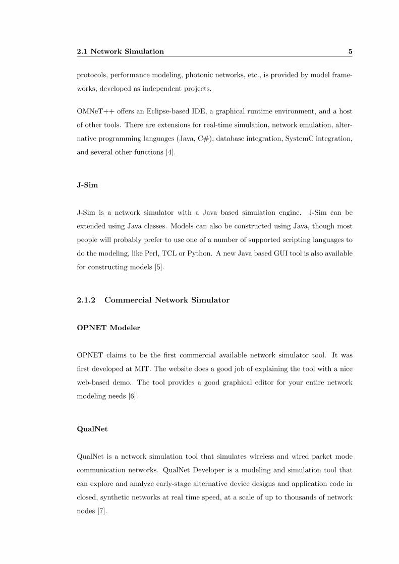
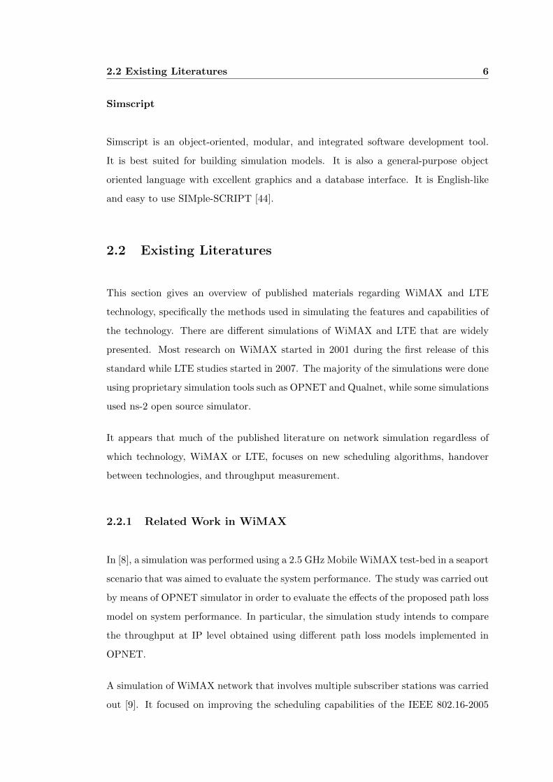
A simulation of WiMAX network that involves multiple subscriber stations was carried
out [9]. It focused on improving the scheduling capabilities of the IEEE 802.16-2005
2.2 Existing Literatures 7
Figure 2.1: Downlink throughput
Figure 2.2: Uplink throughput
broadband wireless networks through multi-queuing algorithms and switching between
those queuing algorithms over time to maximize the performance of the WiMAX sys-
tem.
The simulation is carried out using the OPNET modeler simulator. A detailed simula-
tion study was carried out for the proposed scheduling algorithm, as well as comparing
its performance with some known algorithms such as Proportional Fairness (PF), Round
Robin (RR), and Strict-Priority. The simulation was done using the simulation model
shown in Figure 2.3.

2.2 Existing Literatures 8
Figure 2.3: System Model Implementation in OPNET
This paper also showed measurement analysis and results of scheduler’s performance,
which supports different quality of service (QoS) as shown in Table 2.1. These results
are useful for verification of the cloud-based ns-3-WiMAX network simulation results.
Table 2.1: Throughput using multiple subscriber stations
Much research has been carried out to find methods of obtaining throughput figures
2.2 Existing Literatures 9
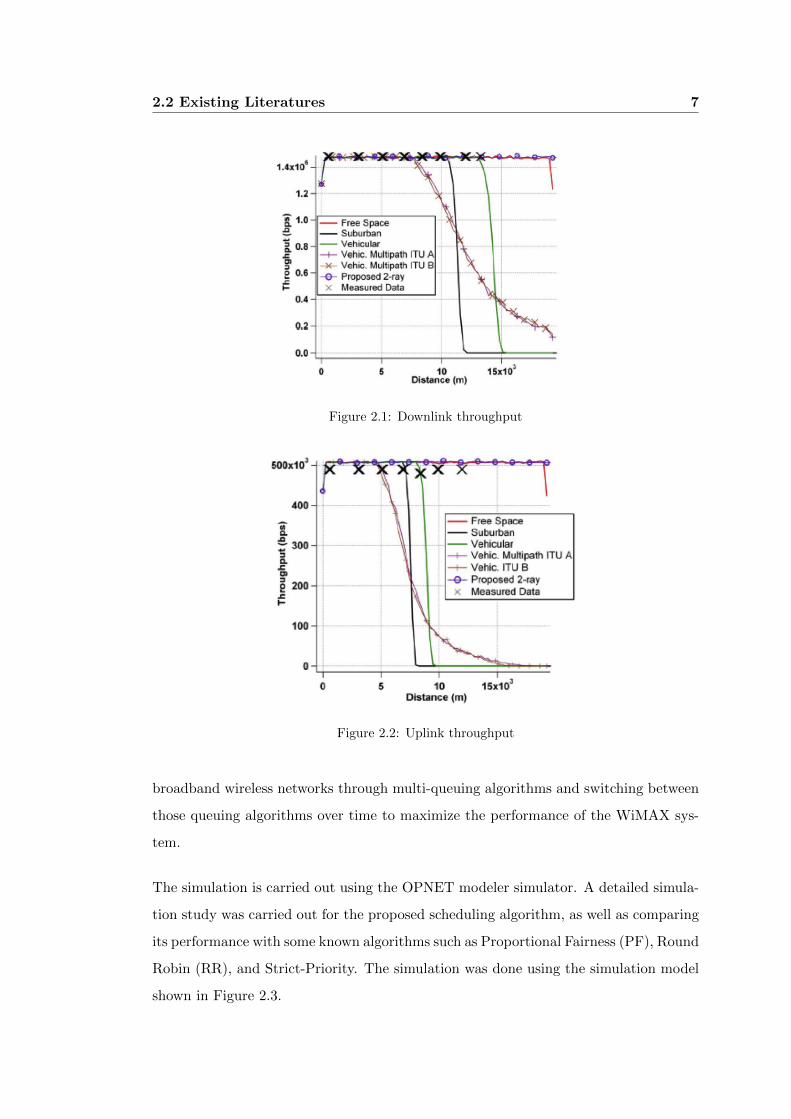
[10]. It is described that the theoretical throughput of PHY layer, MAC layer, and
IP layer can be encapsulated in a MAC SDU (Service Data Unit). A comparative
study was made regarding WiMAX throughput calculations. Figure 2.4 depicts the
theoretical throughput in MAC layer for downlink.
Figure 2.4: MAC Layer throughput
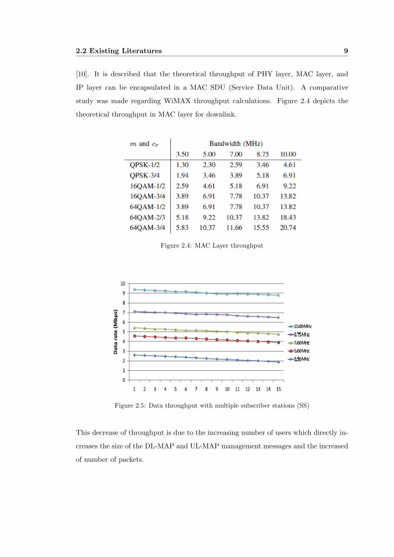
Figure 2.5: Data throughput with multiple subscriber stations (SS)
This decrease of throughput is due to the increasing number of users which directly in-
creases the size of the DL-MAP and UL-MAP management messages and the increased
of number of packets.
2.2 Existing Literatures 10
2.2.2 Related Work in LTE
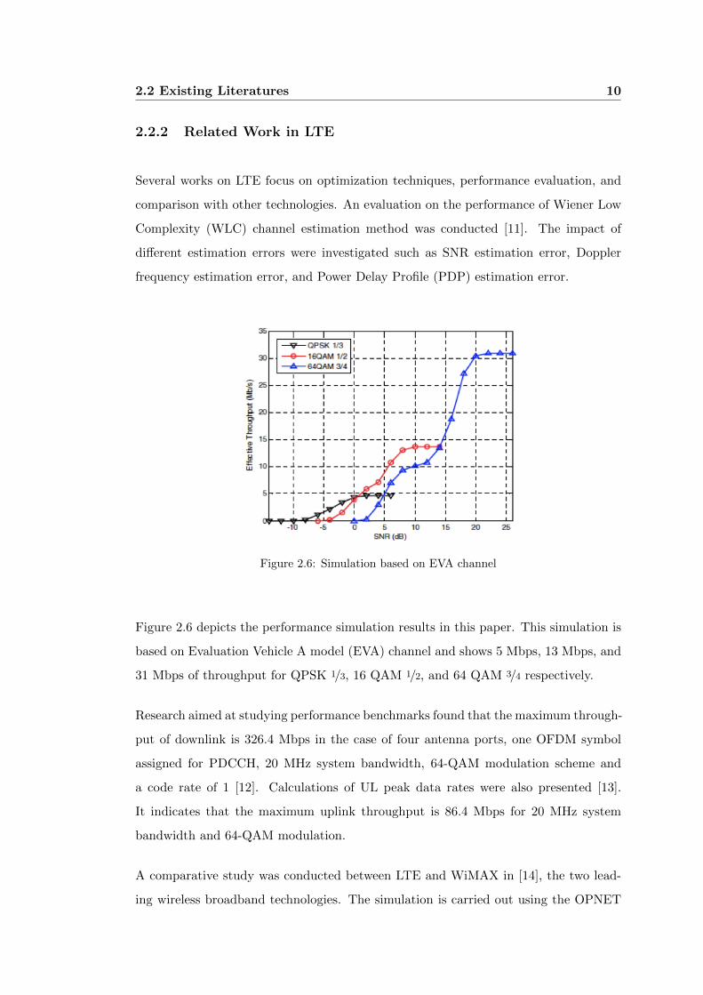
Several works on LTE focus on optimization techniques, performance evaluation, and
comparison with other technologies. An evaluation on the performance of Wiener Low
Complexity (WLC) channel estimation method was conducted [11]. The impact of
different estimation errors were investigated such as SNR estimation error, Doppler
frequency estimation error, and Power Delay Profile (PDP) estimation error.
Figure 2.6: Simulation based on EVA channel
Figure 2.6 depicts the performance simulation results in this paper. This simulation is
based on Evaluation Vehicle A model (EVA) channel and shows 5 Mbps, 13 Mbps, and
31 Mbps of throughput for QPSK 1/3, 16 QAM 1/2, and 64 QAM 3/4 respectively.
Research aimed at studying performance benchmarks found that the maximum through-
put of downlink is 326.4 Mbps in the case of four antenna ports, one OFDM symbol
assigned for PDCCH, 20 MHz system bandwidth, 64-QAM modulation scheme and
a code rate of 1 [12]. Calculations of UL peak data rates were also presented [13].
It indicates that the maximum uplink throughput is 86.4 Mbps for 20 MHz system
bandwidth and 64-QAM modulation.
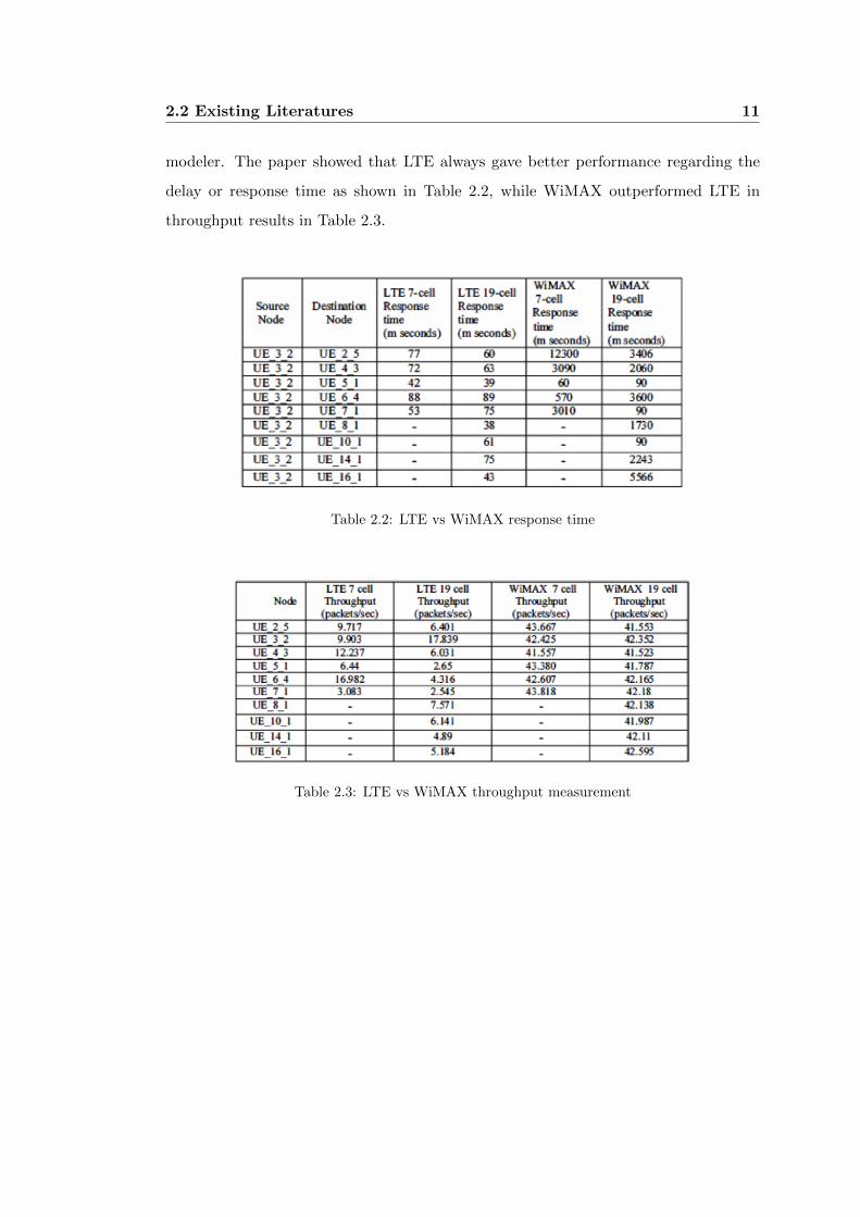
A comparative study was conducted between LTE and WiMAX in [14], the two lead-
ing wireless broadband technologies. The simulation is carried out using the OPNET
2.2 Existing Literatures 11
modeler. The paper showed that LTE always gave better performance regarding the
delay or response time as shown in Table 2.2, while WiMAX outperformed LTE in
throughput results in Table 2.3.
Table 2.2: LTE vs WiMAX response time
Table 2.3: LTE vs WiMAX throughput measurement
Chapter 3
WiMAX Protocol Concept and
Details
3.1 WiMAX Overview
WiMAX stands for Worldwide Interoperability Microwave Access, it is an IP-based
broadband wireless access technology which is similar to a WirelessLAN but provides
a coverage range and service like those existing cellular technologies. WiMAX network
supports both fixed and mobile stations. The earlier version of mobile WiMAX was
a pre-4G network which can achieve 70 Mbps downlink throughput while the latest
WiMAX IEEE 802.16m standard which was approved on March 2011 is a 4G network
which can reach 100 Mbps downlink throughput for mobile stations and 1Gbps for fixed
stations.
The term WiMAX has been commercialized by WiMAX forum which is a non-profit
trade organization that was formed in 2003 and comprises of chipset manufacturers,
communication equipment manufacturers, and telecom operators. The goal of this
group is to certify and promote interoperability of wireless devices that conforms to
IEEE 802.16 and ETSI HiperMan standards. It works closely with service providers
and regulators to ensure that WiMAX Forum certified systems meet customer and gov-
ernment requirements. WiMAX conforms to IEEE (Institute of Electrical and Elec-

3.1 WiMAX Overview 13
tronics Engineers) 802.16 standard which is governed by IEEE Working Group 802.16.
WiMAX is officially called WirelessMAN (Wireless Metropolitan Area Network).
According to WiMAX Forums industry report [19], WiMAX will heavily impact the
future of mobile broadband communication because of its promising features and sup-
port from major chipset manufacturers. WiMAX forum reported 583 deployments as
of May, 2011.
In February 2011, WiMAX Forum announced that as of the end of 2010, WiMAX
service providers cover more than 823 Million people. This estimate surpasses last
years forecast of 800 million people, and signifies that WiMAX is still on target to
reach the forecast that by 2011 there will be over 1 billion people across the world
within WiMAX coverage [19].
Figure 3.1: WiMAX Point of Presence [19]
WiMAX supports 2-11 GHz (unlicensed) OFDM for Non-line-of-sight but only 2-5 GHz
range is commonly used. Table 3.1 shows the list for frequencies used by WiMAX base
station system and the number of deployments.

3.2 Evolution of WiMAX 14
WiMAX Frequency (in GHz) WiMAX Deployments
2.3 48
2.5 112
3.3 10
3.5 308
5+ 21
Table 3.1: WiMAX Deployment by frequency
3.2 Evolution of WiMAX
3.2.1 IEEE 802.16 Standards
The first WirelessMAN standard was approved in October 2001 [20]. It is called IEEE
802.16-2001 which operates in high frequency bands from 10 to 66 GHz and intended
for line-of-sight (LOS) propagation. The standard aims to link homes and businesses
to core telecommunications networks worldwide. An amendment IEEE 802.16a was
released before the end of 2002 which extends the air interface to support low frequency
bands from 2 to 11 GHz band, including both licensed and unlicensed spectrum.
3.2.2 Fixed WiMAX
The next standard IEEE 802.16-2004 which was released in 2004 consolidates revisions
IEEE 802.16-2001, 802.16a, and 802.16c standards [21]. The standard supports primar-
ily point-to-multipoint architecture, with an optional mesh topology. It is structured
to support multiple physical layer suited to a particular operational environment. For
operation frequencies 10-66 GHz, the physical layer (PHY) is based on single-carrier
modulation (S-OFDM). For frequencies below 11 GHz non-line-ofsight (NLOS), mod-
ulation can be based on three schemes such as OFDM, OFDMA and single-carrier
modulation.

3.2 Evolution of WiMAX 15
3.2.3 Mobile WiMAX 1
In 2005, IEEE released the first mobile WiMAX standard. The standard adds mobility
features from the previous standard, which operates in frequencies below 6 GHz, in-
troduces scalable Orthogonal Frequency Division Multiple Access (S-OFDMA) multi-
carrier technique, Multiple-In Multiple-Out (MIMO) antenna system, and enhanced
network security. It also supports adaptive modulation which adjusts the signal mod-
ulation scheme depending on the signal to noise ratio condition of the radio link.
Unlike with other OFDM-based systems such as WLAN, IEEE 802.16e standard sup-
ports variable channel bandwidth sizes from 1.25 to 20 MHz for NLOS operations with
128 to 2048 sub-carriers. The channel bandwidth is the range of frequencies, above
and/or below of the center frequency required for modulation of a signal. The varia-
tion of bandwidth sizes and the requirement to support fixed and mobile usage is part
of scalable OFDM design [23].
3.2.4 Fixed and Mobile WiMAX 1
IEEE 802.16-2009 combined fixed and mobile point-to-multipoint broadband wireless
access (BWA) systems. The standard supports multiple physical layer (PHY) specifi-
cations suited to a particular operational environment.
IEEE 802.16-2009 standard includes previous 802.16-2004 fixed, 802.16e mobile ver-
sions, and among others. The authors of [24] assert that the 2009 standard enables rapid
worldwide deployment of innovative, cost effective, and interoperable multi-vendor
broadband wireless access products.
3.2.5 Mobile WiMAX 2
IEEE approved IEEE802.16m in March 2011, which incorporates some advanced func-
tions relative to the legacy system, new sub-channelization schemes and more efficient
pilot structures in the downlink and uplink to reduce PHY overhead. It is also known
as Mobile WiMAX 2 or WirelessMAN-Advanced [25].
3.3 WiMAX Architecture 16
This standard is one of the two proposed IMT-Advanced standards by International
Mobile Telecommunications (ITU) for fourth- generation (4G) wireless technology, the
other standard is Long Term Evolution Advanced (LTE-Advanced). The goals of IMT-
Advanced are throughput rates of 1 Gbps for fixed stations and 100 Mbps for mobile
stations.
3.3 WiMAX Architecture
3.3.1 WiMAX Network
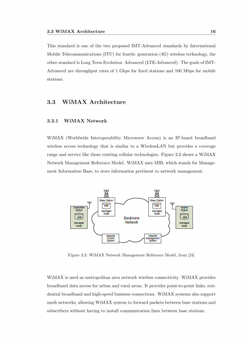
WiMAX (Worldwide Interoperability Microwave Access) is an IP-based broadband
wireless access technology that is similar to a WirelessLAN but provides a coverage
range and service like those existing cellular technologies. Figure 3.2 shows a WiMAX
Network Management Reference Model. WiMAX uses MIB, which stands for Manage-
ment Information Base, to store information pertinent to network management.
Figure 3.2: WiMAX Network Management Reference Model, from [24]
WiMAX is used as metropolitan area network wireless connectivity. WiMAX provides
broadband data access for urban and rural areas. It provides point-to-point links, resi-
dential broadband and high-speed business connections. WiMAX systems also support
mesh networks, allowing WiMAX system to forward packets between base stations and
subscribers without having to install communication lines between base stations.

3.4 Physical Layer 17
3.4 Physical Layer
3.4.1 PHY Layer
The physical layer (PHY) is the lowest layer of 7-layer OSI model of computer net-
working. WiMAX was originally designed for high frequency band but later IEEE re-
leased amendments to support low frequency bands for mobile WiMAX. WiMAX PHY
uses single carrier OFDM for fixed WiMAX and multiple-carrier OFDMA for mobile
WiMAX. The PHY layer is responsible for transporting the data by modulating the
carriers based on different digital modulation schemes.
3.4.2 OFDM and OFDMA System
Orthogonal Frequency Division Multiplexing (OFDM) is a transmission method in
which the total available bandwidth is divided into many sub-carriers and allocates
users in time domain. Orthogonal Frequency Division Multiple Access (OFDMA) is an
access method based on OFDM. It is a multi-user OFDM which allocates users in time
and frequency domain.
Figure 3.3: Frequency-Time Representation of OFDM Signal
Since the data stream in OFDM system is divided into several sub-streams, the duration
of the symbol is increased, which improves the robustness of OFDM to delay spread.
The Cyclic Prefix (CP) eliminates the Inter-Symbol Interference (ISI). CP is a repetition
of the last data samples that is appended at the beginning of the data payload. CP
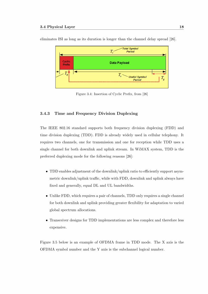
3.4 Physical Layer 18
eliminates ISI as long as its duration is longer than the channel delay spread [26].
Figure 3.4: Insertion of Cyclic Prefix, from [26]
3.4.3 Time and Frequency Division Duplexing
The IEEE 802.16 standard supports both frequency division duplexing (FDD) and
time division duplexing (TDD). FDD is already widely used in cellular telephony. It
requires two channels, one for transmission and one for reception while TDD uses a
single channel for both downlink and uplink stream. In WiMAX system, TDD is the
preferred duplexing mode for the following reasons [26]:
• TDD enables adjustment of the downlink/uplink ratio to efficiently support asym-
metric downlink/uplink traffic, while with FDD, downlink and uplink always have
fixed and generally, equal DL and UL bandwidths.
• Unlike FDD, which requires a pair of channels, TDD only requires a single channel
for both downlink and uplink providing greater flexibility for adaptation to varied
global spectrum allocations.
• Transceiver designs for TDD implementations are less complex and therefore less
expensive.
Figure 3.5 below is an example of OFDMA frame in TDD mode. The X axis is the
OFDMA symbol number and the Y axis is the subchannel logical number.
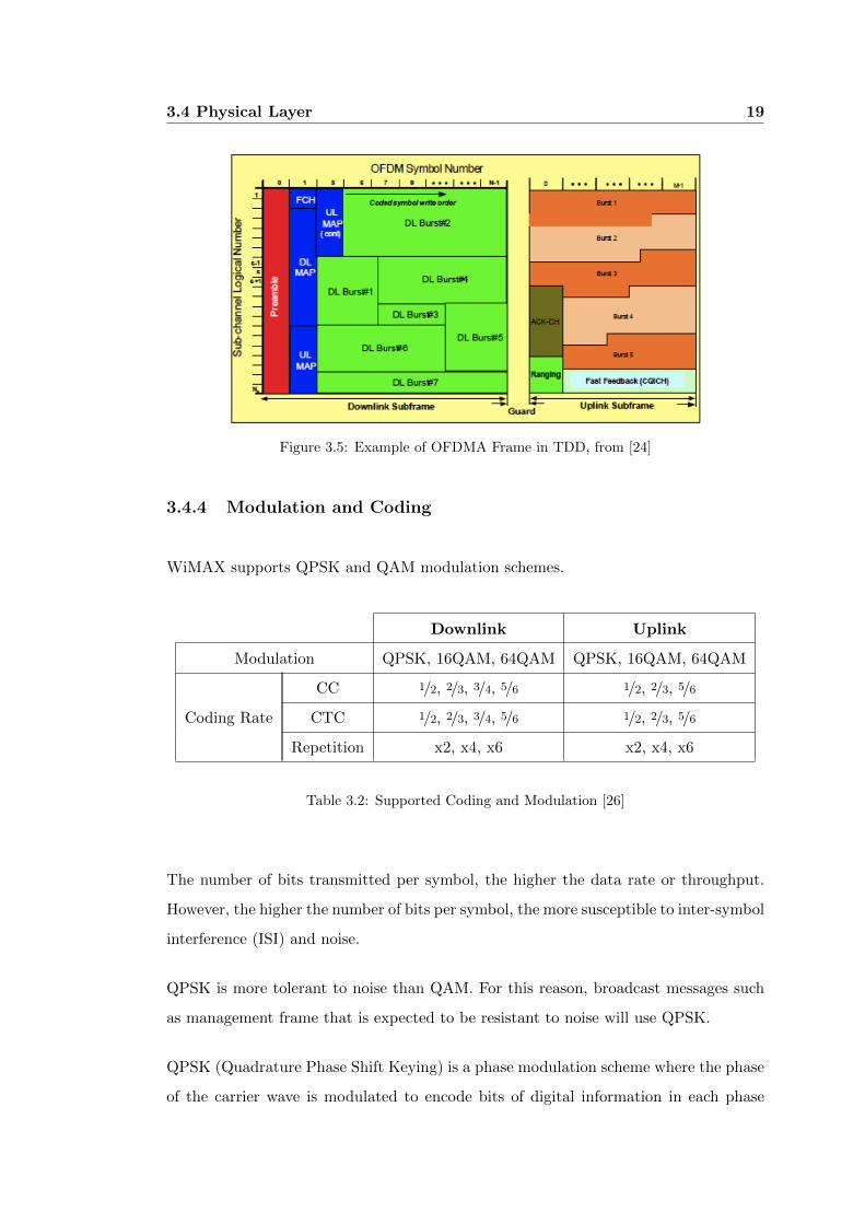
3.4 Physical Layer 19
Figure 3.5: Example of OFDMA Frame in TDD, from [24]
3.4.4 Modulation and Coding
WiMAX supports QPSK and QAM modulation schemes.
Downlink Uplink
Modulation QPSK, 16QAM, 64QAM QPSK, 16QAM, 64QAM
Coding Rate
CC 1/2, 2/3, 3/4, 5/6 1/2, 2/3, 5/6
CTC 1/2, 2/3, 3/4, 5/6 1/2, 2/3, 5/6
Repetition x2, x4, x6 x2, x4, x6
Table 3.2: Supported Coding and Modulation [26]
The number of bits transmitted per symbol, the higher the data rate or throughput.
However, the higher the number of bits per symbol, the more susceptible to inter-symbol
interference (ISI) and noise.
QPSK is more tolerant to noise than QAM. For this reason, broadcast messages such
as management frame that is expected to be resistant to noise will use QPSK.
QPSK (Quadrature Phase Shift Keying) is a phase modulation scheme where the phase
of the carrier wave is modulated to encode bits of digital information in each phase
3.5 Medium Access Control Layer 20
change. QPSK can encode 2 bits per carrier wave.
QAM (Quadrature Amplitude Modulation) is a combination of amplitude modulation
and phase shift keying.
3.5 Medium Access Control Layer
3.5.1 MAC Layer
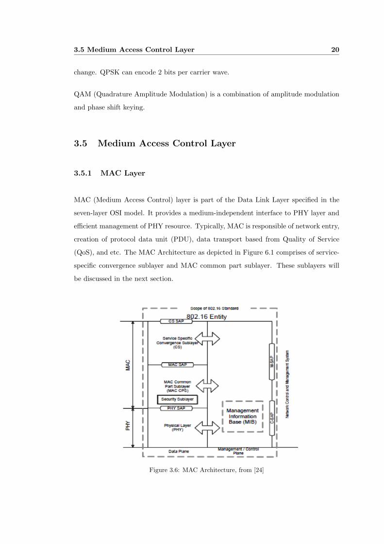
MAC (Medium Access Control) layer is part of the Data Link Layer specified in the
seven-layer OSI model. It provides a medium-independent interface to PHY layer and
efficient management of PHY resource. Typically, MAC is responsible of network entry,
creation of protocol data unit (PDU), data transport based from Quality of Service
(QoS), and etc. The MAC Architecture as depicted in Figure 6.1 comprises of service-
specific convergence sublayer and MAC common part sublayer. These sublayers will
be discussed in the next section.
Figure 3.6: MAC Architecture, from [24]

3.5 Medium Access Control Layer 21
The MAC handles bandwidth request from mobile stations through the following meth-
ods: contention-based (request) and contention-free (polling). With these methods,
the mobile station can request bandwidth and the base station will allocate some re-
source. In contention-based bandwidth request, the mobile station selects a CDMA
code randomly from the codes provided by the base station. This code is modulated
and transmitted during an appropriate uplink allocation.
After receiving the CDMA code successfully, the BS allocates the uplink resource to
mobile station. While in contention-free (polling) process, the BS periodically allocates
bandwidth to the mobile stations [29].
3.5.2 Service-Specific Convergence Sublayer
The Service-Specific Convergence Sublayer is an interface to upper layer protocols. It
accepts data from the higher layer based on the classifier defined. The role of this
sublayer is to transport the service data units (SDUs) to the proper MAC connection
referenced by connection identifiers (CIDs).
Figure 3.7: MAC Service-Specific Convergence Sublayer
The following are two types of convergence sublayer:
3.5 Medium Access Control Layer 22
1. ATM Convergence Sublayer which is responsible for asynchronous transfer mode
(ATM) data transfer.
2. Packet Convergence Sublayer which supports IPv4, IPv6, and Ethernet protocols.
The Packet Convergence Sublayer which supports IP over IEEE 802.16 is discussed
further in Section 3.6.1.
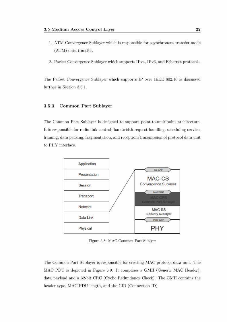
3.5.3 Common Part Sublayer
The Common Part Sublayer is designed to support point-to-multipoint architecture.
It is responsible for radio link control, bandwidth request handling, scheduling service,
framing, data packing, fragmentation, and reception/transmission of protocol data unit
to PHY interface.
Figure 3.8: MAC Common Part Sublyer
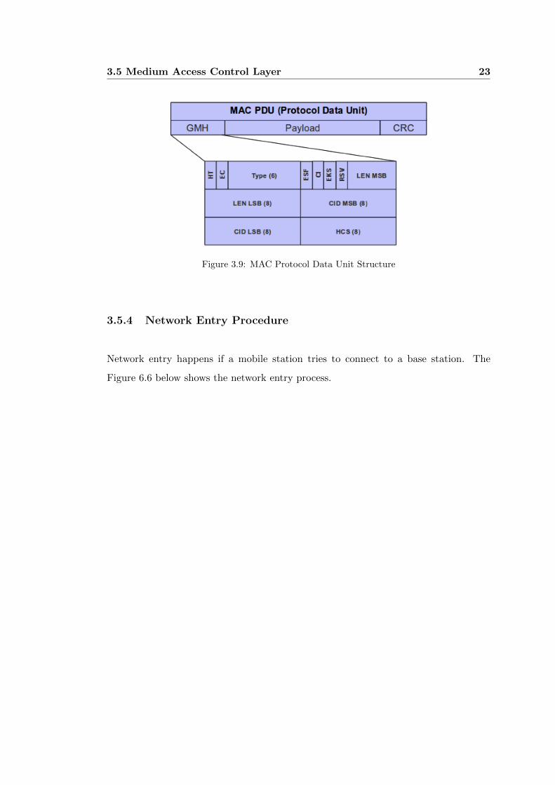
The Common Part Sublayer is responsible for creating MAC protocol data unit. The
MAC PDU is depicted in Figure 3.9. It comprises a GMH (Generic MAC Header),
data payload and a 32-bit CRC (Cyclic Redundancy Check). The GMH contains the
header type, MAC PDU length, and the CID (Connection ID).
3.5 Medium Access Control Layer 23
Figure 3.9: MAC Protocol Data Unit Structure
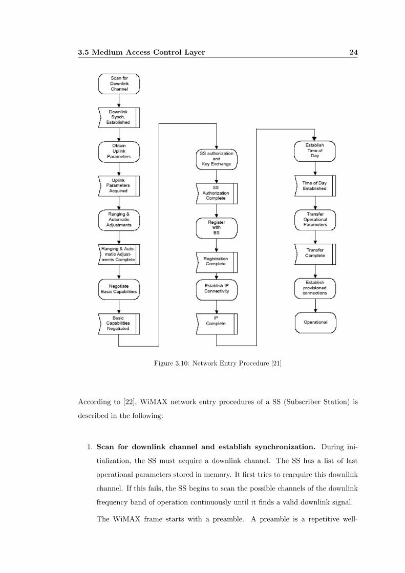
3.5.4 Network Entry Procedure
Network entry happens if a mobile station tries to connect to a base station. The
Figure 6.6 below shows the network entry process.
3.5 Medium Access Control Layer 24
Figure 3.10: Network Entry Procedure [21]
According to [22], WiMAX network entry procedures of a SS (Subscriber Station) is
described in the following:
1. Scan for downlink channel and establish synchronization. During ini-
tialization, the SS must acquire a downlink channel. The SS has a list of last
operational parameters stored in memory. It first tries to reacquire this downlink
channel. If this fails, the SS begins to scan the possible channels of the downlink
frequency band of operation continuously until it finds a valid downlink signal.
The WiMAX frame starts with a preamble. A preamble is a repetitive well-

3.5 Medium Access Control Layer 25
known pattern that SS may use to synchronize timing and frequency from the
BS. Preamble contains preamble index, cell, and segment id.
2. Synchronization. The SS MAC searches for the DL-MAP (Downlink Map)
message. The SS achieves MAC synchronization once it has received at least one
DL-MAP message. An SS MAC remains in synchronization as long as it continues
to successfully receive the DL-MAP and DCD (Downlink Channel Descriptor)
messages of the downlink channel.
After synchronization, the SS waits for a UCD (Uplink Channel Descriptor) message
from the BS in order to obtain the set of transmission parameters needed for a possible
uplink channel. UCD and uplink transmission parameters (UL-MAP) messages are
transmitted periodically by the BS.
3. Perform initial ranging. The main objective of initial ranging is the adjust-
ment of each SS timing offset and power parameters in the initialization phase.
The SS sends RNG-REQ message in a contention-based initial ranging interval.
The BS will then send RNG-RSP which includes the response code, power level,
timing, frequency corrections. If the response code is continue, the MS shall adjust
based from the corrections then resends RNG-REQ. This process will continue
until BS sends RNG-RSP with response code success.
4. Negotiate basic capabilities. This is the phase where SS and BS exchange
their supported parameters. After completion of ranging, the SS informs the
BS of its basic capabilities by transmitting an SBC-REQ (SS Basic Capability
Request) message with its capabilities. The SBC-REQ message is transmitted by
the SS during the initialization (Network Entry) phase to inform the BS of its
basic capabilities.
5. SS authorization and key exchange. Next, the SS has to exchange secure
keys which is part of the authentication mechanism. This is realized through the
PKM protocol. The SS sends a PKM-REQ (Privacy Key Management Request)
message to the BS. The BS responds with a PKM-RSP (Privacy Key Management
Response) message. This process is optional and negotiated during negotiation
of basic capabilities.
3.5 Medium Access Control Layer 26
6. Registration. Registration is the process by which the SS is allowed entry into
the network and, specifically, a managed SS receives its secondary management
CID and thus becomes a manageable SS. On completion of this phase, SS network
entry is done.
The following procedures are optional for Network Entry:
7. Establish IP connectivity. At this point, the SS uses the Dynamic Host Con-
figuration Protocol (DHCP) mechanisms in order to obtain an IP address, from
the DHCP server and any other parameters needed to establish IP connectivity.
8. Establish the time of day. The SS needs to have the current date and time
from the BS. Accuracy is to the nearest second. The protocol by which the SS
retrieves the time of day from a time server through the BS is defined in IETF
RFC 868, which gives the number of seconds starting from year 1900, in 4 bytes.
9. Transfer operational parameters. After the DHCP procedure is successful,
the SS downloads its configuration file using the Trivial File Transfer Protocol
(TFTP) on the SS secondary management connection. The TFTP is a rather
simple protocol used to transfer files, working over the UDP.
3.5.5 Uplink Scheduling Services
Each connection in the uplink direction is mapped to a scheduling service. Each schedul-
ing service is associated with a set of rules imposed on the BS scheduler responsible
for allocating the uplink bandwidth and the request-grant protocol between the SS and
the BS.
3.6 Convergence of IEEE 802.16 MAC and IP Layer 27
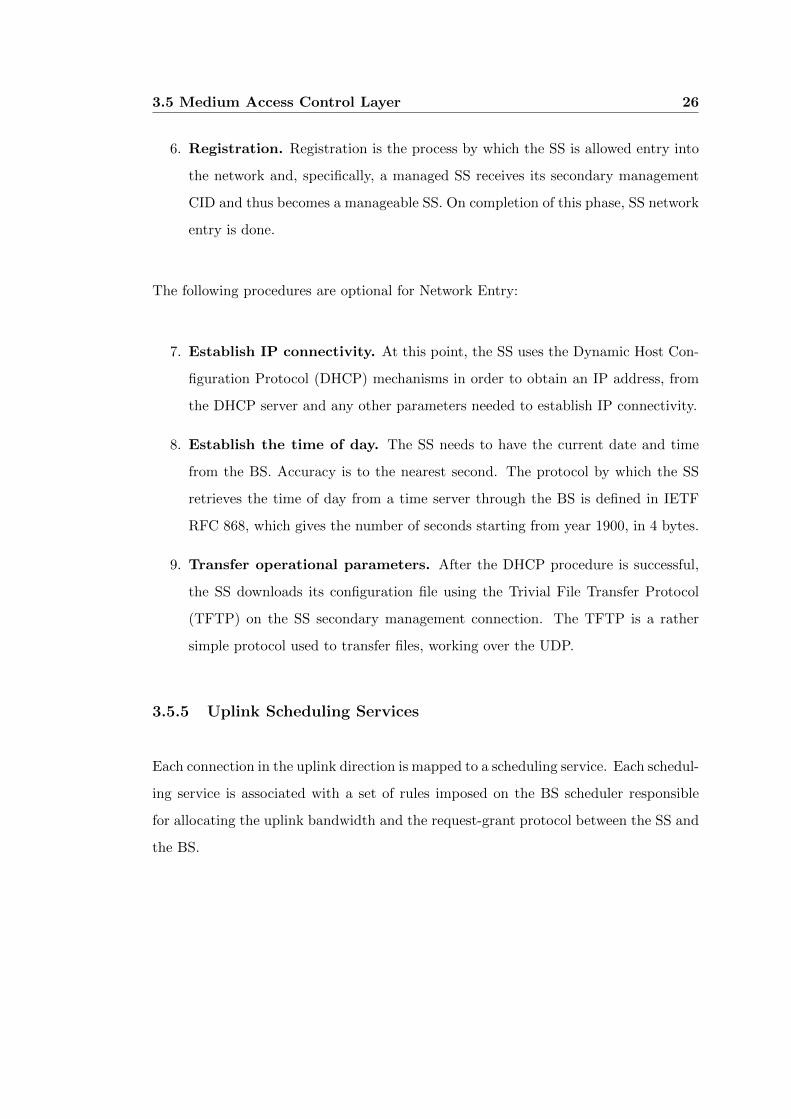
Figure 3.11: WiMAX Quality of Service, from [27]
3.6 Convergence of IEEE 802.16 MAC and IP Layer
This chapter discusses about the transmission and reception of upper-layer protocols
in a WiMAX network. The Packet CS (Packet Convergence Sublayer) is used to trans-
port all packet-based protocols such as the Internet Protocol (IP) and IEEE 802.3
(Ethernet). This chapter specifies the frame format, the Maximum Transmission Unit
(MTU), and the address assignment procedures for transmitting IPv4 packets over the
IP-specific part of the Packet Convergence Sublayer of IEEE 802.16.
3.6.1 IP over IEEE 802.16
The Internet Protocol (IP) is the primary protocol in Internet Layer of the Internet
Protocol Suite. It is responsible of delivering datagrams from the source to the desti-
nation based on their IP addresses. It is a connection-less protocol and it is portable
to any physical link. IEEE 802.16 MAC and PHY layers provide wireless link for the
IP layer [33].
The Internet primarily uses IPv4 protocol for data transmission. IPv4 handles the data
by means of datagrams, which includes a 20-byte IP Header. The header includes a
32-bit source IP address and destination IP address. The maximum length of an IPv4
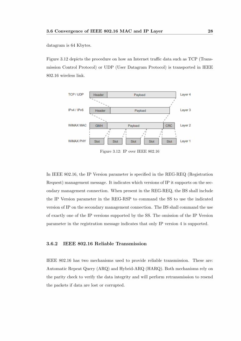
3.6 Convergence of IEEE 802.16 MAC and IP Layer 28
datagram is 64 Kbytes.
Figure 3.12 depicts the procedure on how an Internet traffic data such as TCP (Trans-
mission Control Protocol) or UDP (User Datagram Protocol) is transported in IEEE
802.16 wireless link.
Figure 3.12: IP over IEEE 802.16
In IEEE 802.16, the IP Version parameter is specified in the REG-REQ (Registration
Request) management message. It indicates which versions of IP it supports on the sec-
ondary management connection. When present in the REG-REQ, the BS shall include
the IP Version parameter in the REG-RSP to command the SS to use the indicated
version of IP on the secondary management connection. The BS shall command the use
of exactly one of the IP versions supported by the SS. The omission of the IP Version
parameter in the registration message indicates that only IP version 4 is supported.
3.6.2 IEEE 802.16 Reliable Transmission
IEEE 802.16 has two mechanisms used to provide reliable transmission. These are:
Automatic Repeat Query (ARQ) and Hybrid-ARQ (HARQ). Both mechanisms rely on
the parity check to verify the data integrity and will perform retransmission to resend
the packets if data are lost or corrupted.
3.7 WiMAX Capacity 29
3.6.2.1 ARQ
The ARQ is similar in concept with transmission control protocol (TCP). There are
three types of implementations of ARQ: stop-and-wait, go-back-N, and selective re-
transmission. ARQ is used to ensure reliable data transmission by retransmitting the
corrupted data.
It is a control technique for the data-link layer in which the receiver demands the
transmitter to send again the blocks of data in which errors are detected. The receiver
verifies that the packet was received with errors using the CRC (cyclic redundancy
check) code that is attached to each and every information block. After the CRC
verification, the receiver sends either a positive acknowledgement (ACK) or a negative
acknowledgement (NACK) concerning the reception of the data block [34].
3.6.2.2 HARQ
The HARQ scheme combines two forms of coding for error control: FEC (forward
error correction) and ARQ, making it possible to reduce the number of retransmissions,
potentially increasing the system throughput when compared to ARQ.
When HARQ is used, instead of discarding each erroneously received packet, these
are stored at the receiver side and later combined with their respective retransmitted
copies, increasing the reliability of the transmitted information [34].
3.7 WiMAX Capacity
3.7.1 Channel Capacity
The highest rate of information that can be transmitted through a channel is called
the channel capacity. Channel capacity is affected by several factors such as attenua-
tion, fading, and noise. Shannon’s Channel Capacity Theorem or the Shannon-Hartley
3.7 WiMAX Capacity 30
Theorem is used to measure the channel capacity. The theorem states that:
C = B ·(log2
[1 +
S
N
])bits/sec (3.1)
Where:
C is the channel capacity
B is the channel bandwidth in hertz
S is the signal power
N is the noise power
The channel capacity depends on bandwidth and signal-to-noise ratio, meaning the
channel capacity increases when bandwidth increases as well as signal-to-noise ratio
increases. The Shannon theorem applies only to digital communications because in
analog communications, the concept of capacity, measured in bits/sec, does not apply.
IEEE 802.16 protocol supports adaptive modulation coding which adjusts the signal
modulation scheme depending on the signal to noise ratio condition of the radio link.
When the radio link is high in quality, the highest modulation scheme will be used,
giving the system more capacity.
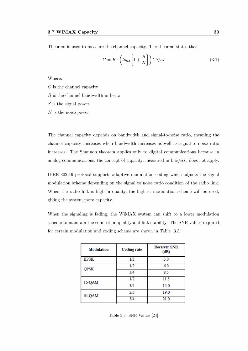
When the signaling is fading, the WiMAX system can shift to a lower modulation
scheme to maintain the connection quality and link stability. The SNR values required
for certain modulation and coding scheme are shown in Table 3.3.
Table 3.3: SNR Values [24]
3.7 WiMAX Capacity 31
3.7.2 PHY Throughput
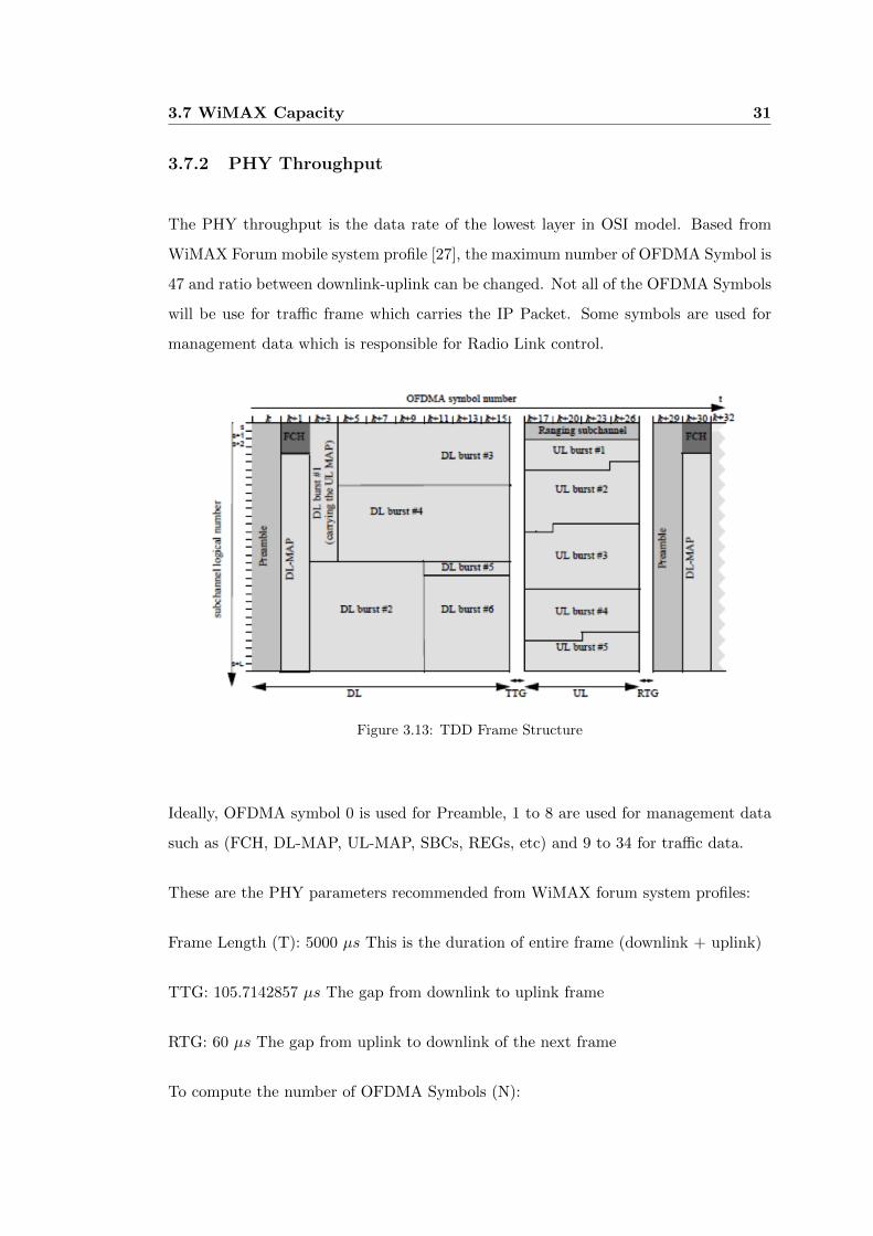
The PHY throughput is the data rate of the lowest layer in OSI model. Based from
WiMAX Forum mobile system profile [27], the maximum number of OFDMA Symbol is
47 and ratio between downlink-uplink can be changed. Not all of the OFDMA Symbols
will be use for traffic frame which carries the IP Packet. Some symbols are used for
management data which is responsible for Radio Link control.
Figure 3.13: TDD Frame Structure
Ideally, OFDMA symbol 0 is used for Preamble, 1 to 8 are used for management data
such as (FCH, DL-MAP, UL-MAP, SBCs, REGs, etc) and 9 to 34 for traffic data.
These are the PHY parameters recommended from WiMAX forum system profiles:
Frame Length (T): 5000 µs This is the duration of entire frame (downlink + uplink)
TTG: 105.7142857 µs The gap from downlink to uplink frame
RTG: 60 µs The gap from uplink to downlink of the next frame
To compute the number of OFDMA Symbols (N):
3.7 WiMAX Capacity 32
[T -
[TTG + RTG
]]Ts
=
[5000 -
[105. 7 + 60
]]102. 86µs
= 47 OFDMA Symbols (3.2)
The computation below will use 35/12 downlink-uplink ratio, meaning the maximum
number of OFDMA Symbols for DL frame is 35 and the remaining 12 ODFMA Symbols
is for UL frame. Since 0 to 8 are used for management messages, the number of OFDMA
Symbols that will be used for traffic frame is 26 (35 minus 9).
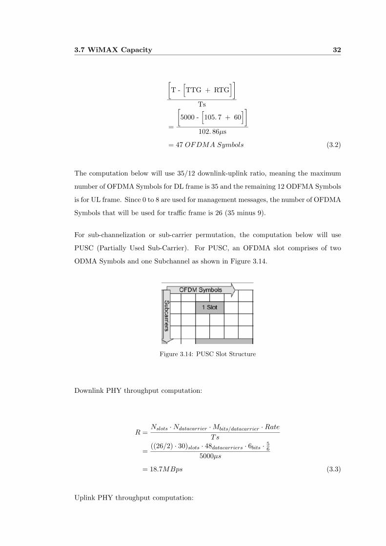
For sub-channelization or sub-carrier permutation, the computation below will use
PUSC (Partially Used Sub-Carrier). For PUSC, an OFDMA slot comprises of two
ODMA Symbols and one Subchannel as shown in Figure 3.14.
Figure 3.14: PUSC Slot Structure
Downlink PHY throughput computation:
R =Nslots ·Ndatacarrier ·Mbits/datacarrier ·Rate
Ts
=((26/2) · 30)slots · 48datacarriers · 6bits · 5
6
5000µs
= 18.7MBps (3.3)
Uplink PHY throughput computation:
3.7 WiMAX Capacity 33
R =Nslots ·Ndatacarrier ·Mbits/datacarrier ·Rate
Ts
=((9/3) · 35)slots · 48datacarriers · 6bits · 5
6
5000µs
= 5.04MBps (3.4)
However, the physical throughput is affected by several aspects such as protocol header
overheads, protocol implementation, and channel condition.
Chapter 4
LTE Protocol Concept and
Details
Long Term Evolution also known as LTE was developed by the 3GPP (3rd Generation
Partnership Project), a collaboration between groups of telecommunication associa-
tions. It was released in the 4th quarter of 2008. The 3GPP partner from the US is the
Alliance for Telecommunications Industry Solutions whose members include telecom-
munication companies such as AT&T, Cisco, and Verizon. The first release called
3GPP Release 8 did not meet the requirements for 4G or IMT-Advanced as defined by
the ITU (International Telecommunication Union). IMT-Advanced requires peak data
rates of up to 1 Gbps for downlink.
With “3GPP Release 10 or LTE-Advanced, the standard managed to meet the 4G
requirements. 3GPP was created in December 1998 by the signing of the “The 3rd
Generation Partnership Project Agreement”. The original scope of 3GPP was to pro-
duce technical specifications and technical reports for a 3G mobile system based on
evolved GSM core networks and radio access technologies. The scope was subsequently
amended to include the maintenance and development of the Global System for Mobile
communication (GSM), General Packet Radio Service (GPRS), and Enhanced Data
rates for GSM Evolution (EDGE) Technical Specifications [35].
LTE supports peak data rates of 100 Mbps in downlink and 50 Mbps in uplink, both

4.1 Overall Architecture 35
using 20 MHz bandwidth. When using MIMO techniques LTE can even reach up to 300
Mbps downlink data rates. It has a variable bandwidth, which can be used with 1.25,
2.5, 5, 10, 15 and 20 MHz. A cell can cover up to 100 km area with slight degradation
after 30 km and reach over 200 users per cell (with at least 5 MHz bandwidth). LTE
is optimized for low speeds of motion such as from 0 to 15 km/h, but it supports also
speeds up to 350 km/h. Round-trip time below 10 ms can be accomplished [36].
4.1 Overall Architecture
The LTE architecture is made up of Evolved Universal Terrestrial Radio Access Network
Node (E-UTRAN) and Evolved Packet Core (EPC). These two components create an
Evolved Packet System (EPS). The EPS routes the IP data from the Packet Data
Network Gateway (PDN-Gateway) to User Equipment (UE).
The E-UTRAN architecture is illustrated in Figure 4.1.
Figure 4.1: Overall Architecture, from [37]
The E-UTRAN consists of E-UTRAN NodeB (eNB), providing the E-UTRA user plane
and control plane protocol terminations towards the UE. The eNBs are interconnected
with each other by means of the X2 interface.
The eNBs are also connected by means of the S1 interface to the EPC (Evolved Packet
Core), more specifically to the MME (Mobility Management Entity) by means of the
4.2 Functional Split 36
S1-MME and to the Serving Gateway (S-GW) by means of the S1-U. The S1 interface
supports a many-to-many relation between MMEs / Serving Gateways and eNBs [37].
The eUTRAN is the air interface of 3GPP’s Long Term Evolution (LTE).
4.2 Functional Split
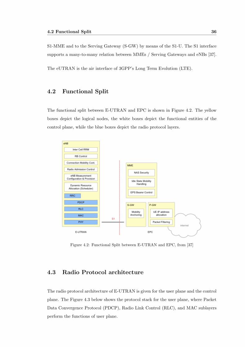
The functional split between E-UTRAN and EPC is shown in Figure 4.2. The yellow
boxes depict the logical nodes, the white boxes depict the functional entities of the
control plane, while the blue boxes depict the radio protocol layers.
Figure 4.2: Functional Split between E-UTRAN and EPC, from [37]
4.3 Radio Protocol architecture
The radio protocol architecture of E-UTRAN is given for the user plane and the control
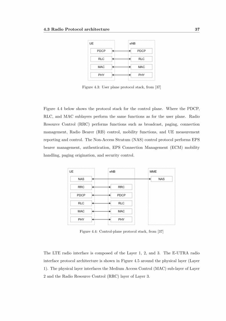
plane. The Figure 4.3 below shows the protocol stack for the user plane, where Packet
Data Convergence Protocol (PDCP), Radio Link Control (RLC), and MAC sublayers
perform the functions of user plane.
4.3 Radio Protocol architecture 37
Figure 4.3: User plane protocol stack, from [37]
Figure 4.4 below shows the protocol stack for the control plane. Where the PDCP,
RLC, and MAC sublayers perform the same functions as for the user plane. Radio
Resource Control (RRC) performs functions such as broadcast, paging, connection
management, Radio Bearer (RB) control, mobility functions, and UE measurement
reporting and control. The Non-Access Stratum (NAS) control protocol performs EPS
bearer management, authentication, EPS Connection Management (ECM) mobility
handling, paging origination, and security control.
Figure 4.4: Control-plane protocol stack, from [37]
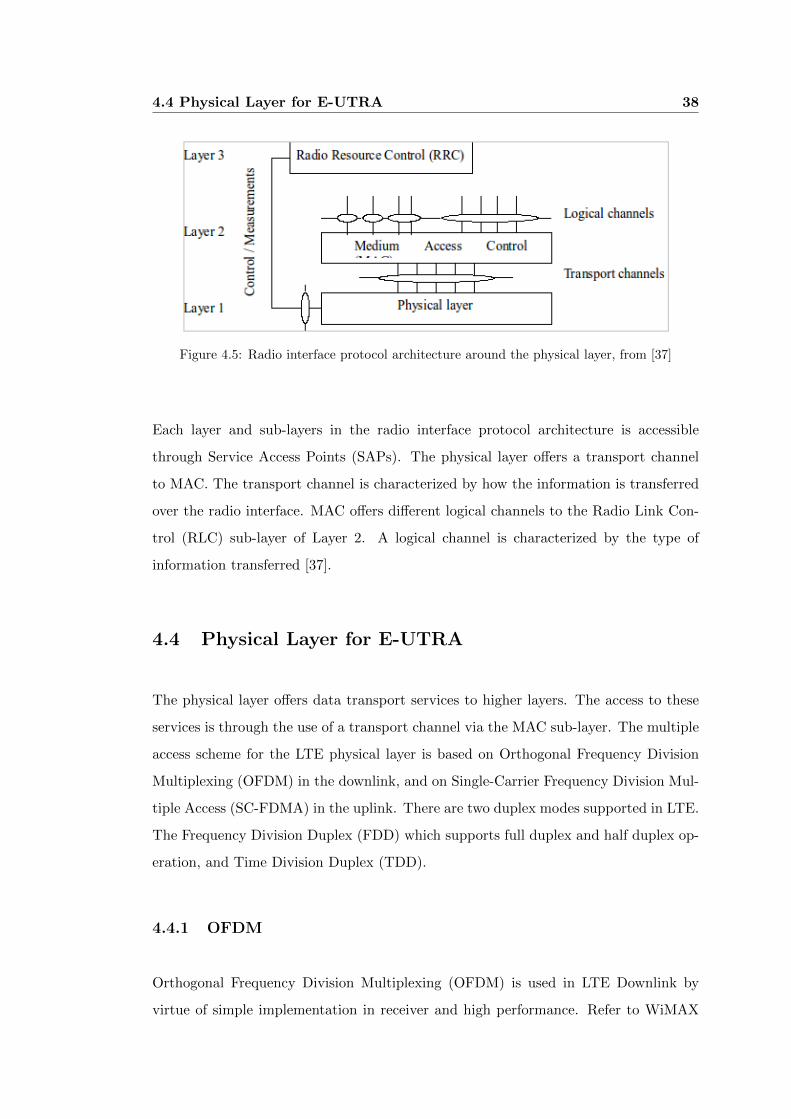
The LTE radio interface is composed of the Layer 1, 2, and 3. The E-UTRA radio
interface protocol architecture is shown in Figure 4.5 around the physical layer (Layer
1). The physical layer interfaces the Medium Access Control (MAC) sub-layer of Layer
2 and the Radio Resource Control (RRC) layer of Layer 3.
4.4 Physical Layer for E-UTRA 38
Figure 4.5: Radio interface protocol architecture around the physical layer, from [37]
Each layer and sub-layers in the radio interface protocol architecture is accessible
through Service Access Points (SAPs). The physical layer offers a transport channel
to MAC. The transport channel is characterized by how the information is transferred
over the radio interface. MAC offers different logical channels to the Radio Link Con-
trol (RLC) sub-layer of Layer 2. A logical channel is characterized by the type of
information transferred [37].
4.4 Physical Layer for E-UTRA
The physical layer offers data transport services to higher layers. The access to these
services is through the use of a transport channel via the MAC sub-layer. The multiple
access scheme for the LTE physical layer is based on Orthogonal Frequency Division
Multiplexing (OFDM) in the downlink, and on Single-Carrier Frequency Division Mul-
tiple Access (SC-FDMA) in the uplink. There are two duplex modes supported in LTE.
The Frequency Division Duplex (FDD) which supports full duplex and half duplex op-
eration, and Time Division Duplex (TDD).
4.4.1 OFDM
Orthogonal Frequency Division Multiplexing (OFDM) is used in LTE Downlink by
virtue of simple implementation in receiver and high performance. Refer to WiMAX
4.4 Physical Layer for E-UTRA 39
Chapter 3.
4.4.2 OFDMA
Orthogonal Frequency Division Multiple Access (OFDMA) is a multi-user version of
OFDM. Multiple access is achieved by assigning different OFDM sub-channels to differ-
ent users. Robustness to fading and interference are among the advantages of OFDMA.
Refer to WiMAX Chapter 3.
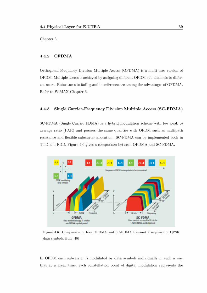
4.4.3 Single Carrier-Frequency Division Multiple Access (SC-FDMA)
SC-FDMA (Single Carrier FDMA) is a hybrid modulation scheme with low peak to
average ratio (PAR) and possess the same qualities with OFDM such as multipath
resistance and flexible subcarrier allocation. SC-FDMA can be implemented both in
TTD and FDD. Figure 4.6 gives a comparison between OFDMA and SC-FDMA.
Figure 4.6: Comparison of how OFDMA and SC-FDMA transmit a sequence of QPSK
data symbols, from [40]
In OFDM each subcarrier is modulated by data symbols individually in such a way
that at a given time, each constellation point of digital modulation represents the
4.5 LTE Layer 2 40
amplitude of each subcarrier. However, in SC-FDMA, the linear combination of all
data symbols that are transmitted at the same time is modulated to a given subcarrier.
In a given symbol period, all transmitted subcarriers of a SC-FDMA signal are carrying
a component of each modulated data symbol. This is known as a single carrier scheme
of SC-FDMA.
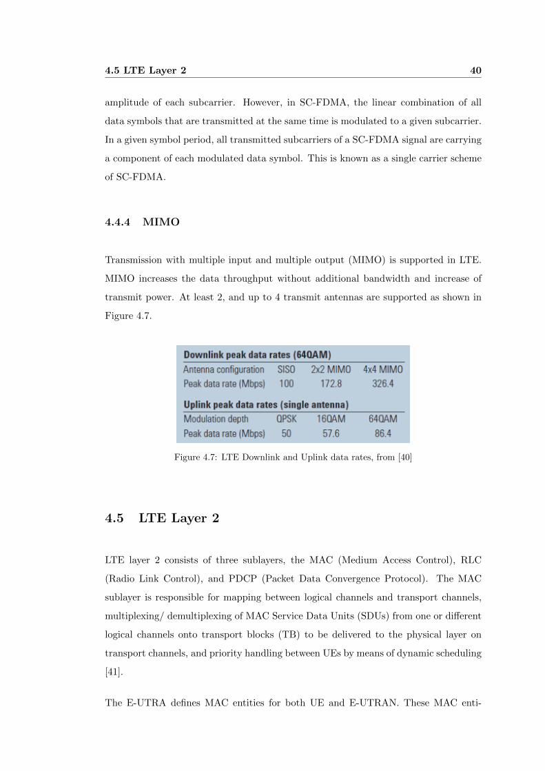
4.4.4 MIMO
Transmission with multiple input and multiple output (MIMO) is supported in LTE.
MIMO increases the data throughput without additional bandwidth and increase of
transmit power. At least 2, and up to 4 transmit antennas are supported as shown in
Figure 4.7.
Figure 4.7: LTE Downlink and Uplink data rates, from [40]
4.5 LTE Layer 2
LTE layer 2 consists of three sublayers, the MAC (Medium Access Control), RLC
(Radio Link Control), and PDCP (Packet Data Convergence Protocol). The MAC
sublayer is responsible for mapping between logical channels and transport channels,
multiplexing/ demultiplexing of MAC Service Data Units (SDUs) from one or different
logical channels onto transport blocks (TB) to be delivered to the physical layer on
transport channels, and priority handling between UEs by means of dynamic scheduling
[41].
The E-UTRA defines MAC entities for both UE and E-UTRAN. These MAC enti-
4.5 LTE Layer 2 41
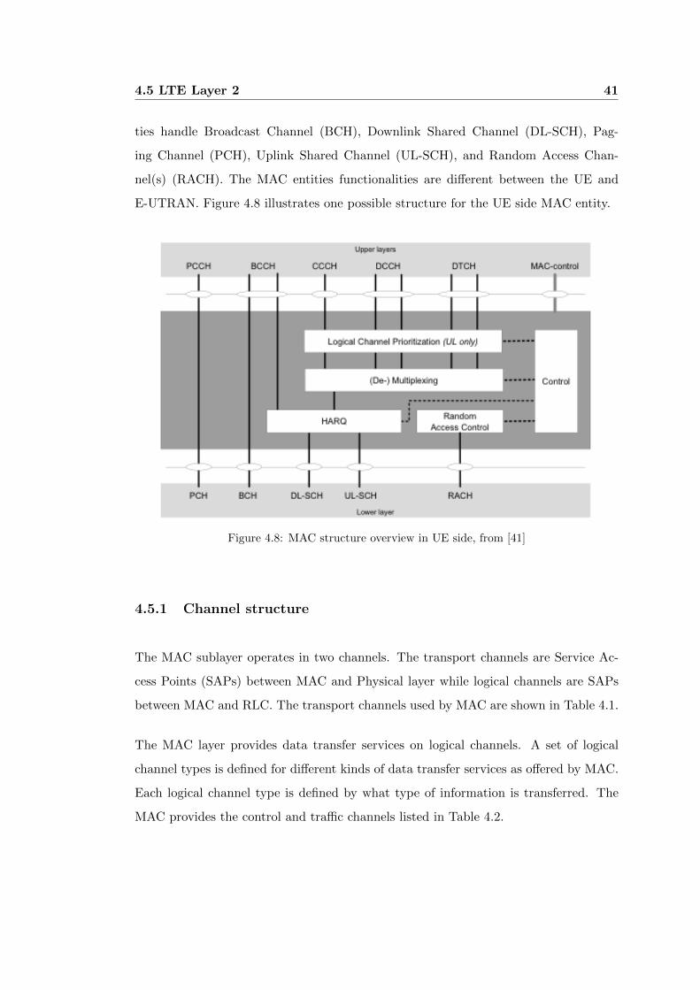
ties handle Broadcast Channel (BCH), Downlink Shared Channel (DL-SCH), Pag-
ing Channel (PCH), Uplink Shared Channel (UL-SCH), and Random Access Chan-
nel(s) (RACH). The MAC entities functionalities are different between the UE and
E-UTRAN. Figure 4.8 illustrates one possible structure for the UE side MAC entity.
Figure 4.8: MAC structure overview in UE side, from [41]
4.5.1 Channel structure
The MAC sublayer operates in two channels. The transport channels are Service Ac-
cess Points (SAPs) between MAC and Physical layer while logical channels are SAPs
between MAC and RLC. The transport channels used by MAC are shown in Table 4.1.
The MAC layer provides data transfer services on logical channels. A set of logical
channel types is defined for different kinds of data transfer services as offered by MAC.
Each logical channel type is defined by what type of information is transferred. The
MAC provides the control and traffic channels listed in Table 4.2.
4.5 LTE Layer 2 42
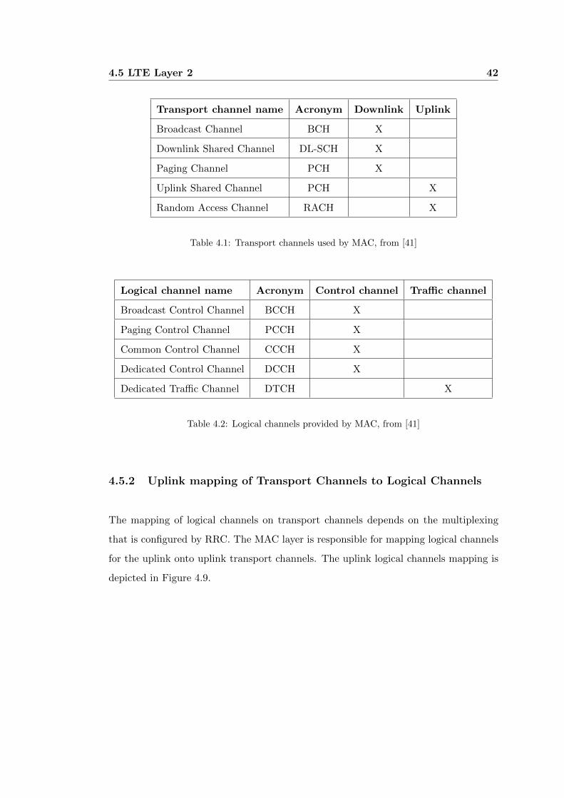
Transport channel name Acronym Downlink Uplink
Broadcast Channel BCH X
Downlink Shared Channel DL-SCH X
Paging Channel PCH X
Uplink Shared Channel PCH X
Random Access Channel RACH X
Table 4.1: Transport channels used by MAC, from [41]
Logical channel name Acronym Control channel Traffic channel
Broadcast Control Channel BCCH X
Paging Control Channel PCCH X
Common Control Channel CCCH X
Dedicated Control Channel DCCH X
Dedicated Traffic Channel DTCH X
Table 4.2: Logical channels provided by MAC, from [41]
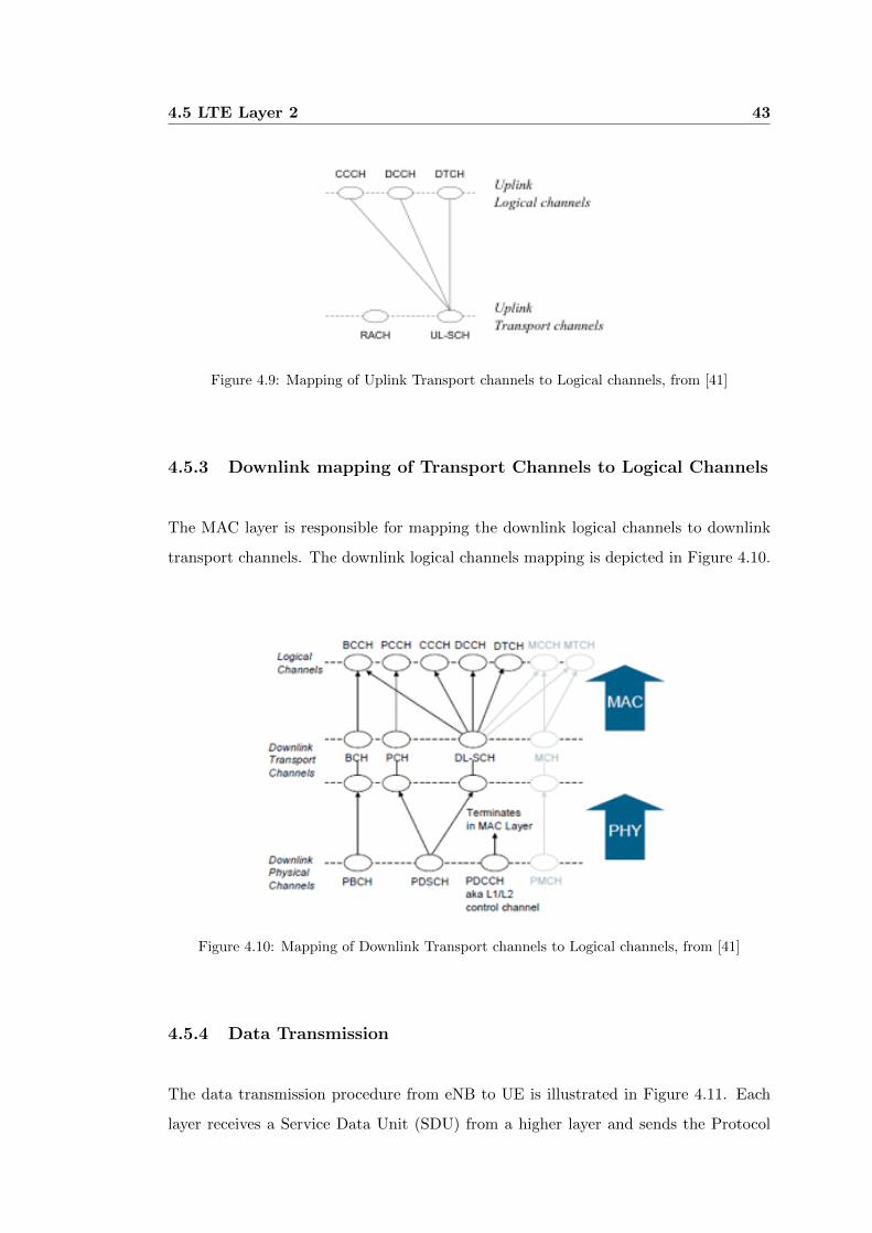
4.5.2 Uplink mapping of Transport Channels to Logical Channels
The mapping of logical channels on transport channels depends on the multiplexing
that is configured by RRC. The MAC layer is responsible for mapping logical channels
for the uplink onto uplink transport channels. The uplink logical channels mapping is
depicted in Figure 4.9.
4.5 LTE Layer 2 43
Figure 4.9: Mapping of Uplink Transport channels to Logical channels, from [41]
4.5.3 Downlink mapping of Transport Channels to Logical Channels
The MAC layer is responsible for mapping the downlink logical channels to downlink
transport channels. The downlink logical channels mapping is depicted in Figure 4.10.
Figure 4.10: Mapping of Downlink Transport channels to Logical channels, from [41]
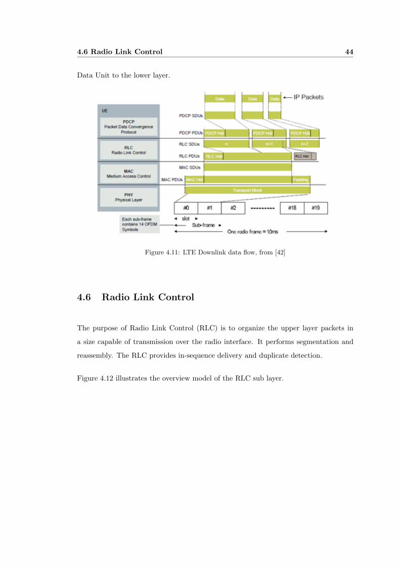
4.5.4 Data Transmission
The data transmission procedure from eNB to UE is illustrated in Figure 4.11. Each
layer receives a Service Data Unit (SDU) from a higher layer and sends the Protocol
4.6 Radio Link Control 44
Data Unit to the lower layer.
Figure 4.11: LTE Downlink data flow, from [42]
4.6 Radio Link Control
The purpose of Radio Link Control (RLC) is to organize the upper layer packets in
a size capable of transmission over the radio interface. It performs segmentation and
reassembly. The RLC provides in-sequence delivery and duplicate detection.
Figure 4.12 illustrates the overview model of the RLC sub layer.

4.7 Packet Data Convergence Protocol 45
Figure 4.12: Overview model of the RLC sub layer
4.7 Packet Data Convergence Protocol
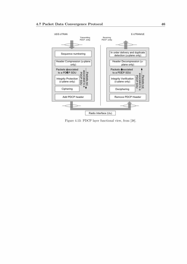
4.7.1 PDCP structure
Packet Data Convergence Protocol (PDCP) is associated either to the control plane
or the user plane depending on which radio bearer it is carrying data for. PDCP
functions in the user plane include decryption, Robust Header Compression (ROHC)
header decompression, sequence numbering, and duplicate removal. PDCP functions
in the control plane include decryption, integrity protection, sequence numbering, and
duplicate removal. There is one PDCP instance per radio bearer. The radio bearer is
similar to a logical channel for user control data [38].
PDCP provides its services to the RRC and user plane upper layers. The services
provided are transfer of user plane data and control plane data, header compression,
ciphering and integrity protection.
The maximum supported size of a PDCP SDU is 8188 octets.
4.7 Packet Data Convergence Protocol 46
Figure 4.13: PDCP layer functional view, from [38].
Chapter 5
WiMAX and LTE Comparison
IEEE 802.16e with migration to 802.16m will share similar performance capabilities
with LTE as both technologies exploit similar wireless and IP design techniques to
approach the maximum spectral efficiencies defined by Shannons Law (approximately
6 bits per hertz). With 802.16e operators can deliver upwards of 3.5 bits per hertz today
(35 Mbps per sector for a 10 MHz channel), while 802.16m and LTE will advance that
to over 5.0 bits per Hertz (greater than 100 Mbps per sector for a 20 MHz channel) as
has been already demonstrated in a number of field tests [28].
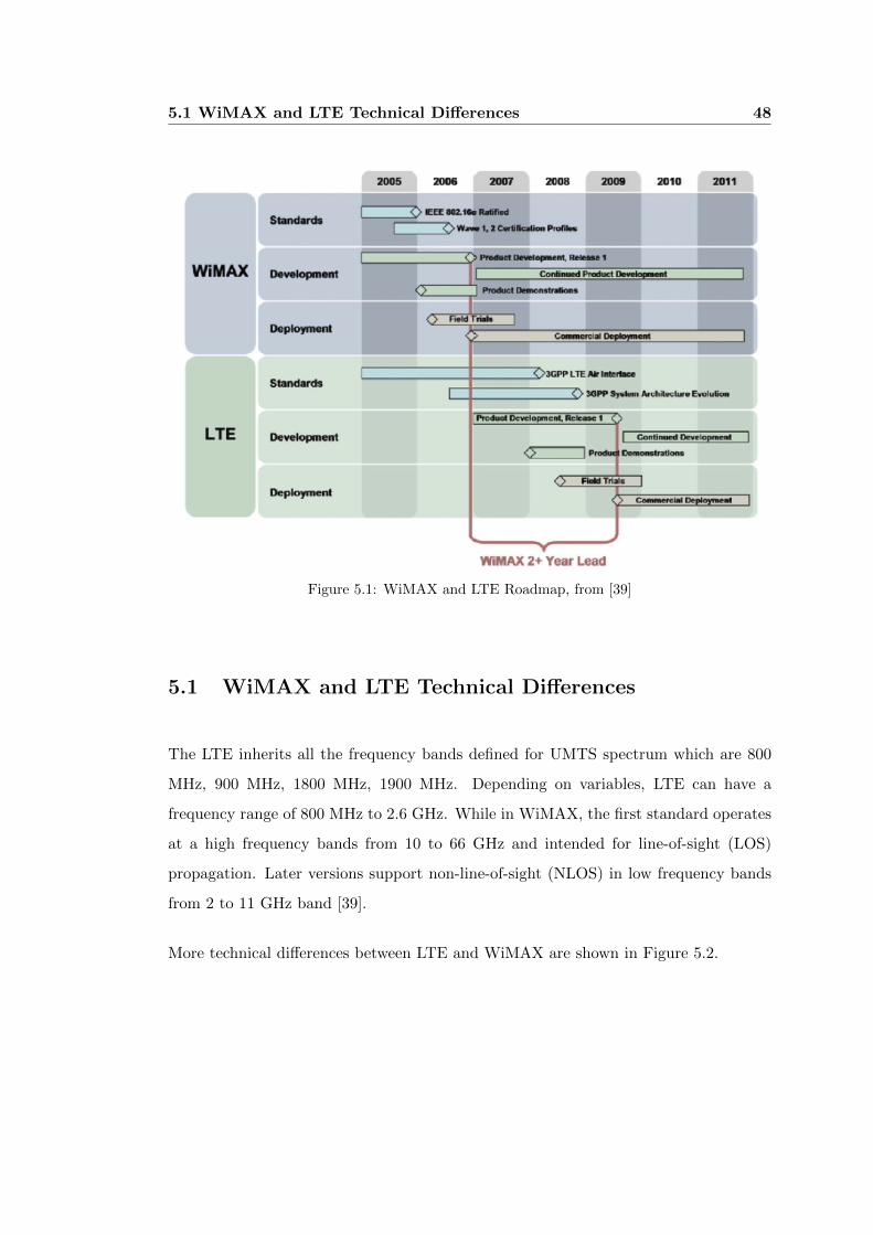
Figure 5.1 below shows WiMAX 802.16e has a two-year head start over LTE. This
was asserted in 2007 by the authors in [28]. The availability of WiMAX solutions in
the market today provide operators a distinct time to market advantage for deploy-
ing high capacity wireless broadband networks. Operators with appropriate spectrum
holdings seeking a time to market advantage for deploying new, differentiated services
will consider WiMAX as their technology platform of choice.
5.1 WiMAX and LTE Technical Differences 48
Figure 5.1: WiMAX and LTE Roadmap, from [39]
5.1 WiMAX and LTE Technical Differences
The LTE inherits all the frequency bands defined for UMTS spectrum which are 800
MHz, 900 MHz, 1800 MHz, 1900 MHz. Depending on variables, LTE can have a
frequency range of 800 MHz to 2.6 GHz. While in WiMAX, the first standard operates
at a high frequency bands from 10 to 66 GHz and intended for line-of-sight (LOS)
propagation. Later versions support non-line-of-sight (NLOS) in low frequency bands
from 2 to 11 GHz band [39].
More technical differences between LTE and WiMAX are shown in Figure 5.2.

5.2 WiMAX Deployments 49
Figure 5.2: WiMAX and LTE Technical Differences [39]
5.2 WiMAX Deployments
The Figure 5.3 shows the map of WiMAX deployments worldwide. The red pins rep-
resent 802.16d deployments, while the blue pins represent 802.16e deployments. These
deployments were last updated in August, 2011 [45].
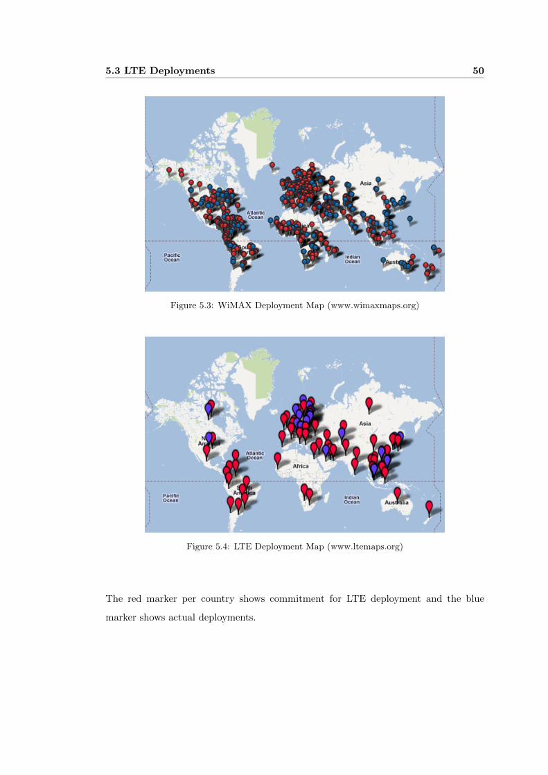
5.3 LTE Deployments
Figure 5.4 shows all global LTE deployments and commitments. It includes a variety
of commitments, including intentions to do trial, deploy, and migrate [46].
5.3 LTE Deployments 50
Figure 5.3: WiMAX Deployment Map (www.wimaxmaps.org)
Figure 5.4: LTE Deployment Map (www.ltemaps.org)
The red marker per country shows commitment for LTE deployment and the blue
marker shows actual deployments.

Chapter 6
Cloud-based Simulator Design
and Implementation
The purpose of this dissertation is to implement a cloud-based network simulator which
uses ns-3 open source network simulator and NetML network analysis and design soft-
ware. This system has existed for more than 6 years ago but lacks of graphical network
editor until the version NetML 4.0.
NetML 4.0 uses Google Web Toolkit (GWT) for the GUI development. The user
interface allows simple networks to be displayed and edited through a web interface [43].
NetML 4.0 design was initially intended to support network simulation but currently
not yet supported. This paper will extend the capability of NetML 4.0 in integrating
it with the new and powerful network simulator ns-3. This means that a script is
generated by NetML 4.0 which can be used as input to the network simulation system
and after a simulation has been completed, a collection of statistics is collected and
transformed into an XML file. The output file from network simulator will then be
used by NetML 4.0 for display purpose and analysis.
Since the new system for network simulation uses web interface as GUI with all the
processes and computation will be done in the server, this could create a cloud comput-
ing for network simulation and design. The proposed cloud-based simulator will likely
be hosted by an institution such as USQ or any organization. It is recommended to be

6.1 Features 52
deployed in a Linux Server PC with high processing speed.
6.1 Features
The cloud-based network simulator supports full network simulation for the next gener-
ation wireless technology, specifically WiMAX and LTE protocols. The system allows
the user to create a wireless network such as base station/subscriber station for WiMAX
or eNodeB/eUEs for LTE. The parameters for WiMAX and LTE network can be also
manipulated. The system currently supports two types of test-bed or test scenario:
ping test and throughput measurement.
The ping test allows the NetML user to check the links between base stations and
subscriber stations. Ping test works by sending an ICMP echo request packet to a des-
tination host and waits for the ICMP response. It measures the time from transmission
to reception or the round-trip time and checks the packet loss. It is also possible to
simulate a noisy wireless channel condition by simply changing the SNR value.
The throughput test simulates a wireless throughput measurement. It measures the
average rate of successful message delivery over a communication channel. The through-
put is measured in bits per second (bps). It supports simultaneous tests of all subscriber
stations and user equipments. In Chapter 7, simulation of the two tests are performed
and the results displayed. Table 6.1 displays the summary of all features supported by
the system.
Simulation Features
WiMAX Network Simulation
- Creation of multiple subscriber stations
- Creation of base station
- Setting of service flow type
- Setting of modulation coding rate
- Simulation of noisy channel condition
- Setting up the connection between nodes
LTE Network Simulation
- Creation of multiple subscriber stations
- Creation of base station
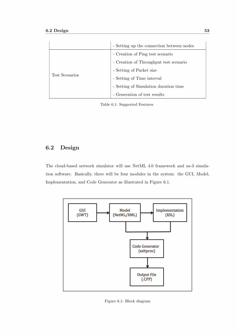
6.2 Design 53
- Setting up the connection between nodes
Test Scenarios
- Creation of Ping test scenario
- Creation of Throughput test scenario
- Setting of Packet size
- Setting of Time interval
- Setting of Simulation duration time
- Generation of test results
Table 6.1: Supported Features
6.2 Design
The cloud-based network simulator will use NetML 4.0 framework and ns-3 simula-
tion software. Basically, there will be four modules in the system: the GUI, Model,
Implementation, and Code Generator as illustrated in Figure 6.1.
Figure 6.1: Block diagram
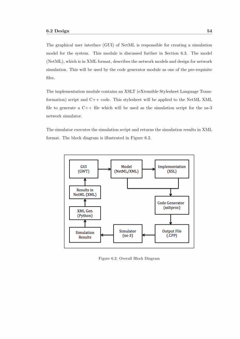
6.2 Design 54
The graphical user interface (GUI) of NetML is responsible for creating a simulation
model for the system. This module is discussed further in Section 6.3. The model
(NetML), which is in XML format, describes the network models and design for network
simulation. This will be used by the code generator module as one of the pre-requisite
files.
The implementation module contains an XSLT (eXtensible Stylesheet Language Trans-
formation) script and C++ code. This stylesheet will be applied to the NetML XML
file to generate a C++ file which will be used as the simulation script for the ns-3
network simulator.
The simulator executes the simulation script and returns the simulation results in XML
format. The block diagram is illustrated in Figure 6.2.
Figure 6.2: Overall Block Diagram
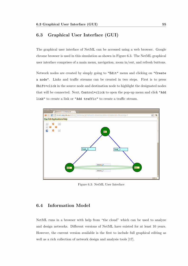
6.3 Graphical User Interface (GUI) 55
6.3 Graphical User Interface (GUI)
The graphical user interface of NetML can be accessed using a web browser. Google
chrome browser is used in this simulation as shown in Figure 6.3. The NetML graphical
user interface comprises of a main menu, navigation, zoom in/out, and refresh buttons.
Network nodes are created by simply going to "Edit" menu and clicking on "Create
a node". Links and traffic streams can be created in two steps. First is to press
Shift+click in the source node and destination node to highlight the designated nodes
that will be connected. Next, Control+click to open the pop-up menu and click "Add
link" to create a link or "Add traffic" to create a traffic stream.
Figure 6.3: NetML User Interface
6.4 Information Model
NetML runs in a browser with help from “the cloud” which can be used to analyze
and design networks. Different versions of NetML have existed for at least 10 years.
However, the current version available is the first to include full graphical editing as
well as a rich collection of network design and analysis tools [17].

6.4 Information Model 56
NetML provides a way to navigate through views of one network, and through a network
of networks. The software itself is networked and provides the means for network
researchers to jointly develop networks and algorithms for research and educational
purposes. It was used in the layered design of Mobile Backhaul Networks [18].
6.4.1 NetML XML
NetML XML is a language for describing network models and design for simulation. It
is based on XML. The focus of researchers and engineers in network simulation is on
conceptual aspects rather than on configuration issues. Hence, the cloud-based simu-
lator would simplify network design. It allows quick configuration and implementation
of a network test-bed.
Figure 6.4 depicts the simple NetML design of a WiMAX Network. The network design
comprises of a base station and two subscriber stations.
Figure 6.4: A simple NetML WiMAX Network
The bsNodes element has a child element bsNode that contains information about the
base station as shown in Figure 6.5. The parameters are name, xposition, and yposition.
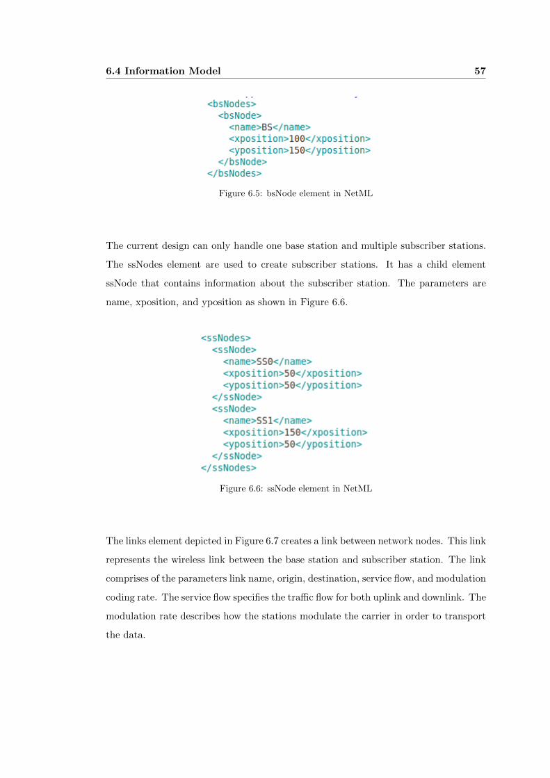
6.4 Information Model 57
Figure 6.5: bsNode element in NetML
The current design can only handle one base station and multiple subscriber stations.
The ssNodes element are used to create subscriber stations. It has a child element
ssNode that contains information about the subscriber station. The parameters are
name, xposition, and yposition as shown in Figure 6.6.
Figure 6.6: ssNode element in NetML
The links element depicted in Figure 6.7 creates a link between network nodes. This link
represents the wireless link between the base station and subscriber station. The link
comprises of the parameters link name, origin, destination, service flow, and modulation
coding rate. The service flow specifies the traffic flow for both uplink and downlink. The
modulation rate describes how the stations modulate the carrier in order to transport
the data.
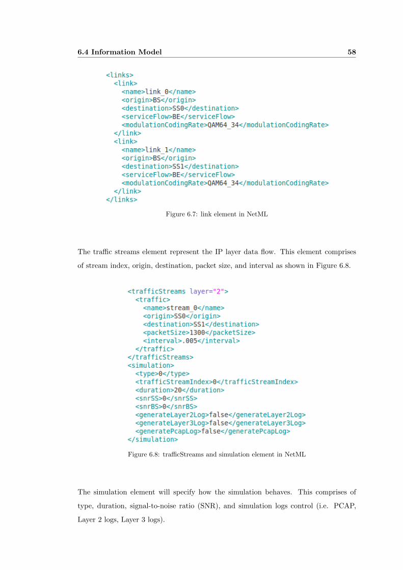
6.4 Information Model 58
Figure 6.7: link element in NetML
The traffic streams element represent the IP layer data flow. This element comprises
of stream index, origin, destination, packet size, and interval as shown in Figure 6.8.
Figure 6.8: trafficStreams and simulation element in NetML
The simulation element will specify how the simulation behaves. This comprises of
type, duration, signal-to-noise ratio (SNR), and simulation logs control (i.e. PCAP,
Layer 2 logs, Layer 3 logs).
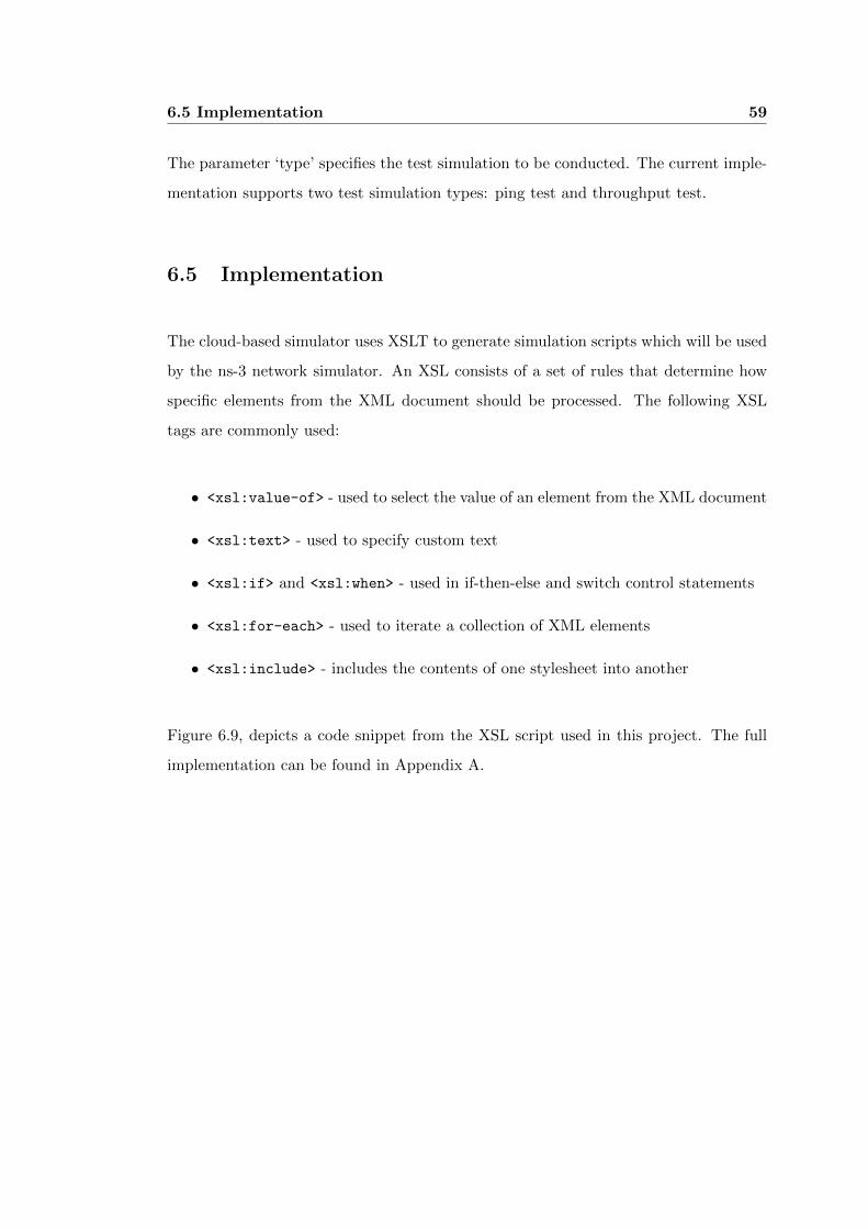
6.5 Implementation 59
The parameter ‘type’ specifies the test simulation to be conducted. The current imple-
mentation supports two test simulation types: ping test and throughput test.
6.5 Implementation
The cloud-based simulator uses XSLT to generate simulation scripts which will be used
by the ns-3 network simulator. An XSL consists of a set of rules that determine how
specific elements from the XML document should be processed. The following XSL
tags are commonly used:
• <xsl:value-of> - used to select the value of an element from the XML document
• <xsl:text> - used to specify custom text
• <xsl:if> and <xsl:when> - used in if-then-else and switch control statements
• <xsl:for-each> - used to iterate a collection of XML elements
• <xsl:include> - includes the contents of one stylesheet into another
Figure 6.9, depicts a code snippet from the XSL script used in this project. The full
implementation can be found in Appendix A.

6.5 Implementation 60
Figure 6.9: XSL Script code snippet
The XSL style sheet begins with an XML declaration: <?xml version="1.0" encoding="UTF-8"?>.
The element <xsl:stylesheet>, defines that this document is an XSLT style sheet
document, specifies the version number, and XSLT namespace attributes.
The <xsl:template match="/"> attribute associates the template with the root of the
XML source document.
The content inside the <xsl:template> element will be a C++ code which will be
used as simulation script for ns-3. This includes the #include “preprocessor” direc-
tives, declaration of variables, functions, and the main function. The <xsl:value-of>
element is used retrieve the values from the XML elements.
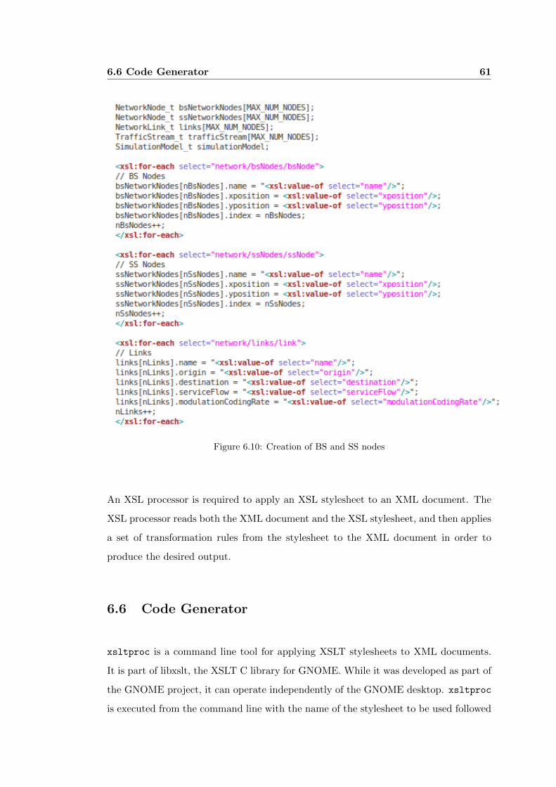
6.6 Code Generator 61
Figure 6.10: Creation of BS and SS nodes
An XSL processor is required to apply an XSL stylesheet to an XML document. The
XSL processor reads both the XML document and the XSL stylesheet, and then applies
a set of transformation rules from the stylesheet to the XML document in order to
produce the desired output.
6.6 Code Generator
xsltproc is a command line tool for applying XSLT stylesheets to XML documents.
It is part of libxslt, the XSLT C library for GNOME. While it was developed as part of
the GNOME project, it can operate independently of the GNOME desktop. xsltproc
is executed from the command line with the name of the stylesheet to be used followed
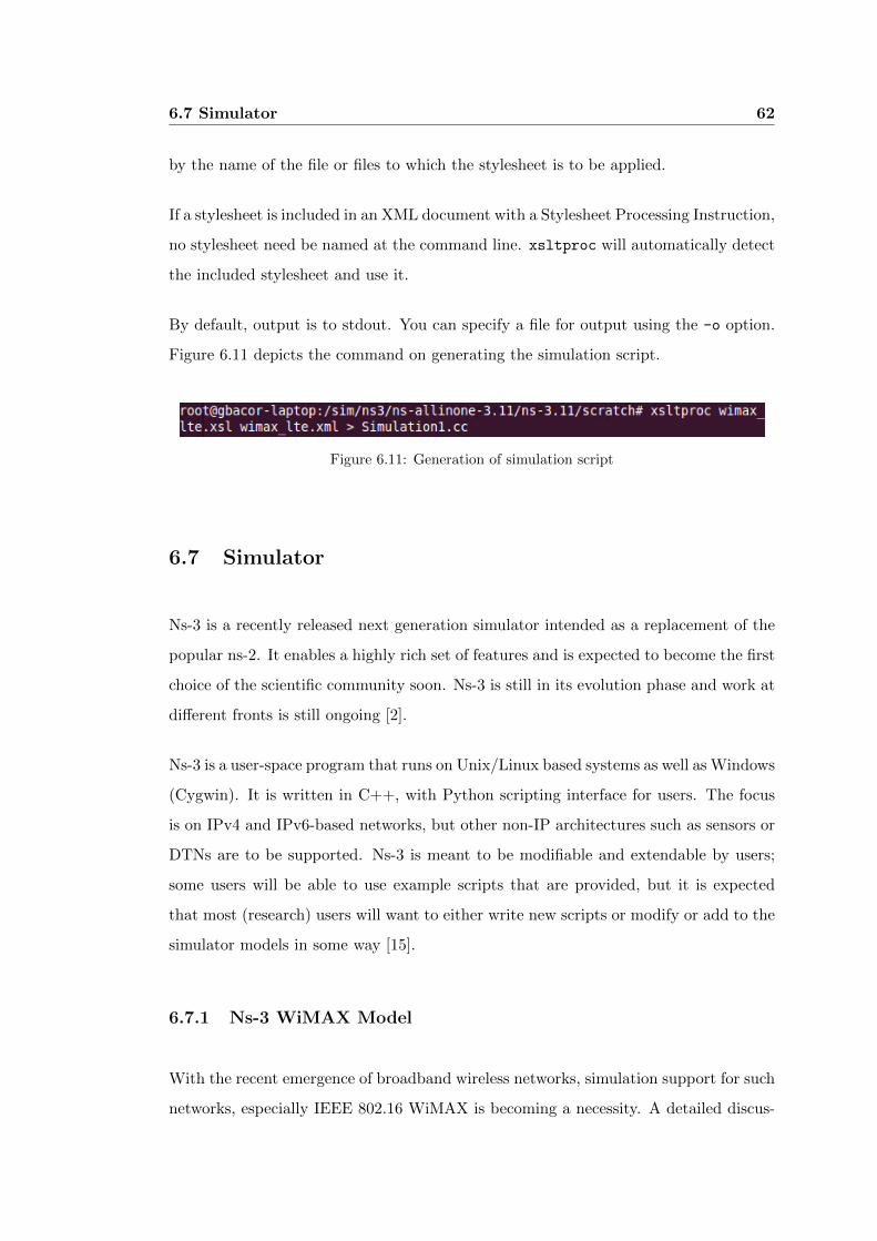
6.7 Simulator 62
by the name of the file or files to which the stylesheet is to be applied.
If a stylesheet is included in an XML document with a Stylesheet Processing Instruction,
no stylesheet need be named at the command line. xsltproc will automatically detect
the included stylesheet and use it.
By default, output is to stdout. You can specify a file for output using the -o option.
Figure 6.11 depicts the command on generating the simulation script.
Figure 6.11: Generation of simulation script
6.7 Simulator
Ns-3 is a recently released next generation simulator intended as a replacement of the
popular ns-2. It enables a highly rich set of features and is expected to become the first
choice of the scientific community soon. Ns-3 is still in its evolution phase and work at
different fronts is still ongoing [2].
Ns-3 is a user-space program that runs on Unix/Linux based systems as well as Windows
(Cygwin). It is written in C++, with Python scripting interface for users. The focus
is on IPv4 and IPv6-based networks, but other non-IP architectures such as sensors or
DTNs are to be supported. Ns-3 is meant to be modifiable and extendable by users;
some users will be able to use example scripts that are provided, but it is expected
that most (research) users will want to either write new scripts or modify or add to the
simulator models in some way [15].
6.7.1 Ns-3 WiMAX Model
With the recent emergence of broadband wireless networks, simulation support for such
networks, especially IEEE 802.16 WiMAX is becoming a necessity. A detailed discus-
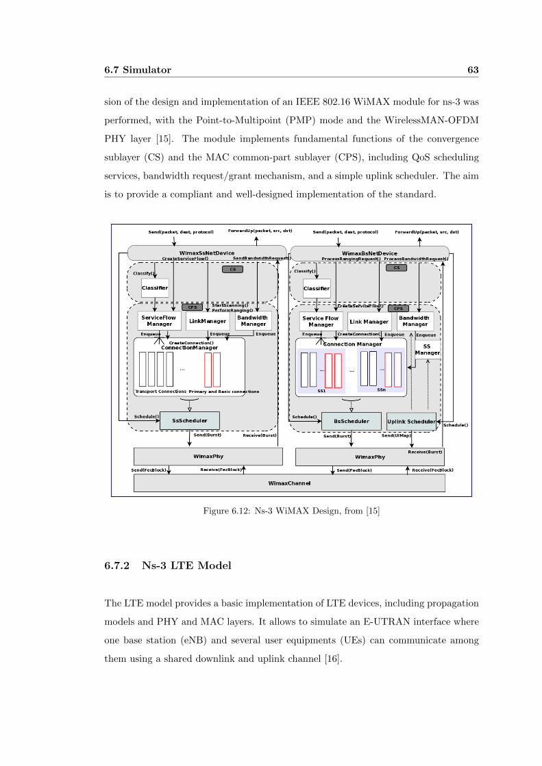
6.7 Simulator 63
sion of the design and implementation of an IEEE 802.16 WiMAX module for ns-3 was
performed, with the Point-to-Multipoint (PMP) mode and the WirelessMAN-OFDM
PHY layer [15]. The module implements fundamental functions of the convergence
sublayer (CS) and the MAC common-part sublayer (CPS), including QoS scheduling
services, bandwidth request/grant mechanism, and a simple uplink scheduler. The aim
is to provide a compliant and well-designed implementation of the standard.
Figure 6.12: Ns-3 WiMAX Design, from [15]
6.7.2 Ns-3 LTE Model
The LTE model provides a basic implementation of LTE devices, including propagation
models and PHY and MAC layers. It allows to simulate an E-UTRAN interface where
one base station (eNB) and several user equipments (UEs) can communicate among
them using a shared downlink and uplink channel [16].

6.7 Simulator 64
Figure 6.13: Ns-3 LTE Design, from [16]
6.7.3 Running the Simulator
In ns-3, the simulation script can be written in C++ or Python. For the purpose of
this dissertation, I decided to use C++ for flexibility. Figure 6.14 depicts the command
to generate the simulation script.

6.8 Network Simulator Output File 65
Figure 6.14: Running the ns-3 script
6.8 Network Simulator Output File
After the simulation has been completed, a collection of statistics is gathered and
transformed into an XML file. The output file from the network simulator will then be
used by the NetML 4.0 for display purpose and analysis. A python script will be used
to open and parse the output file generated by the ns-3 network simulator.
Figure 6.15: Python srcipt for parsing the ns-3 output file
The simulation output file is shown in Figure 6.16. The output is in NetML XML
format which shall be used by the NetML GUI. The parameters are the traffic stream
index, total tx sent, total rx received, lost packet count, and throughput rate.

6.9 Limitations 66
Figure 6.16: Simulation Output
6.9 Limitations
The system has a couple of weaknesses mainly because of the limitation of the ns-3
network simulator and some hardware constraints. Another difficulty is concerning
the great deal of time involved in implementing the system. Table 6.2 depicts the
limitations of the system.
Simulation Limitations
WiMAX Network Simulation
- Supports only one base station
- No mobility support
- No propagation model support
- No support for 64QAM 5/6, 64QAM 1/2, and
16QAM 3/4
LTE Network Simulation - Supports only one base station
Test Scenarios
- Computation of Round trip time (RTT) is not
yet supported
- Low throughput due to lack of Packing support
of ns-3 WiMAX module
- Minimal information on output file
Table 6.2: Limitations
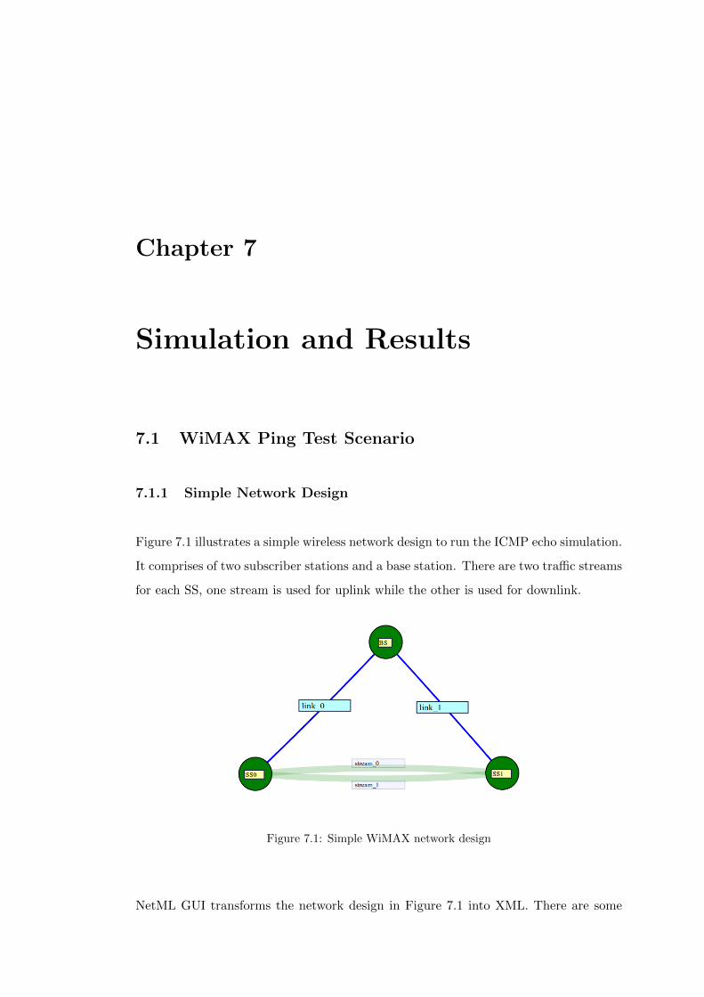
Chapter 7
Simulation and Results
7.1 WiMAX Ping Test Scenario
7.1.1 Simple Network Design
Figure 7.1 illustrates a simple wireless network design to run the ICMP echo simulation.
It comprises of two subscriber stations and a base station. There are two traffic streams
for each SS, one stream is used for uplink while the other is used for downlink.
Figure 7.1: Simple WiMAX network design
NetML GUI transforms the network design in Figure 7.1 into XML. There are some

7.2 WiMAX Multiple Subscriber Stations Throughput Test Scenario 68
additional steps before ping test scenario can be run as shown in Figure 7.2.
Figure 7.2: Configuration of Ping test scenario
7.1.2 Simulation Results
The output of ping test scenario is depicted in Figure 7.3.
Figure 7.3: Ping test output
7.2 WiMAX Multiple Subscriber Stations Throughput Test
Scenario
7.2.1 NetML Network Design
The Figure 7.4 below shows the network design of WiMAX with multiple subscriber
stations. In this network design, the throughput measurement will be simulated.
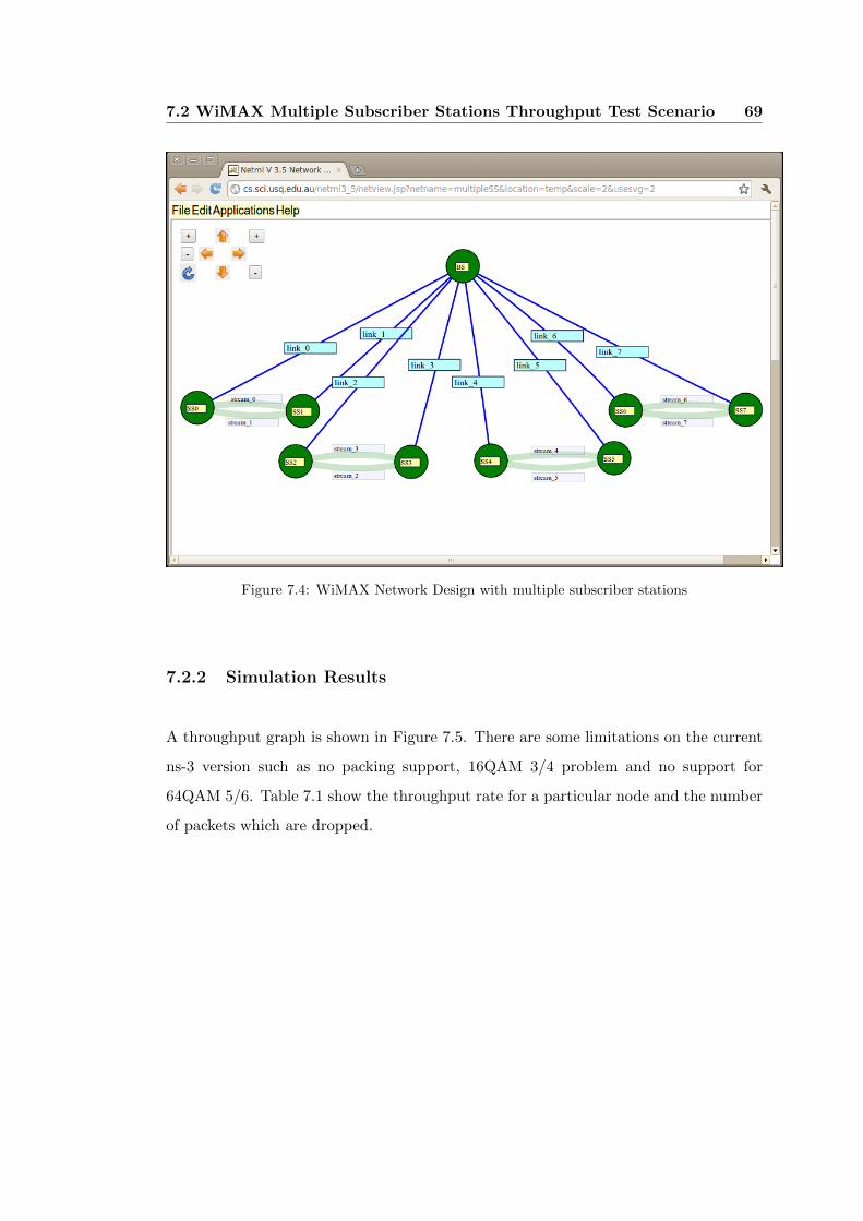
7.2 WiMAX Multiple Subscriber Stations Throughput Test Scenario 69
Figure 7.4: WiMAX Network Design with multiple subscriber stations
7.2.2 Simulation Results
A throughput graph is shown in Figure 7.5. There are some limitations on the current
ns-3 version such as no packing support, 16QAM 3/4 problem and no support for
64QAM 5/6. Table 7.1 show the throughput rate for a particular node and the number
of packets which are dropped.

7.2 WiMAX Multiple Subscriber Stations Throughput Test Scenario 70
Figure 7.5: Throughput Results
Table 7.1: Throughput and no. of dropped packets for 8 subscriber stations
In the latest WiMAX specification, they often use mobile station rather than subscriber
station but on this paper, subscriber station is used since ns-3 is using subscriber
stations.
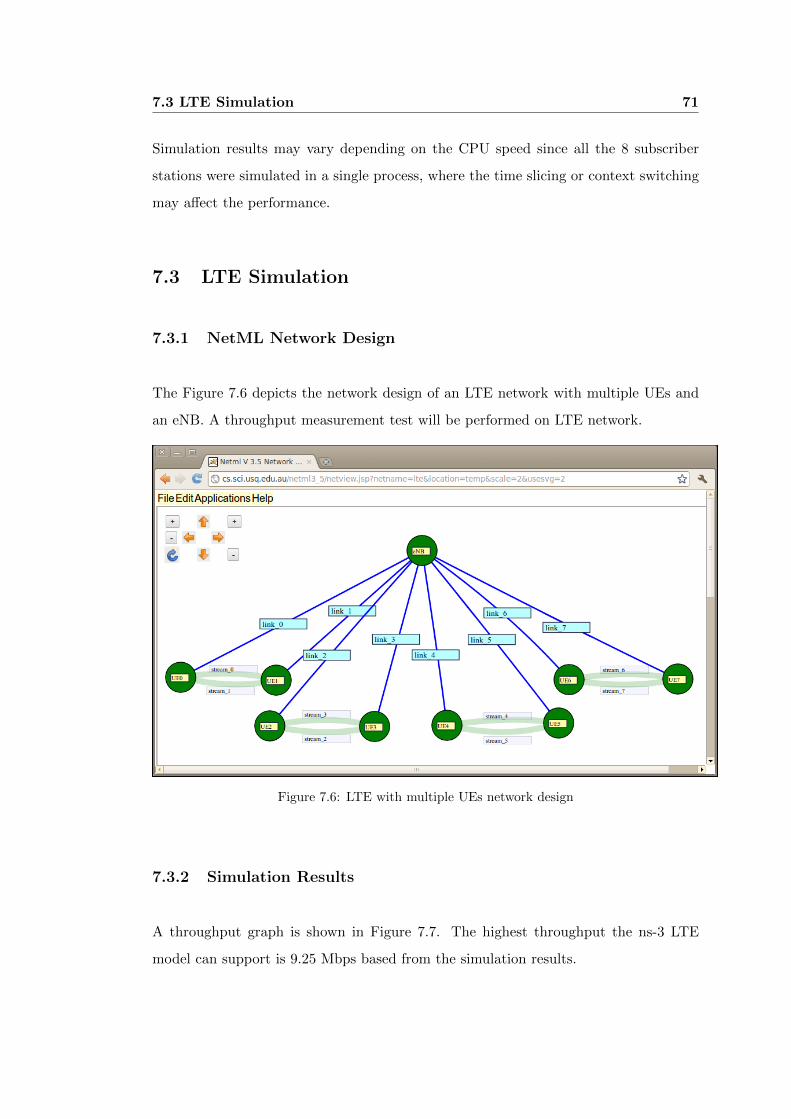
7.3 LTE Simulation 71
Simulation results may vary depending on the CPU speed since all the 8 subscriber
stations were simulated in a single process, where the time slicing or context switching
may affect the performance.
7.3 LTE Simulation
7.3.1 NetML Network Design
The Figure 7.6 depicts the network design of an LTE network with multiple UEs and
an eNB. A throughput measurement test will be performed on LTE network.
Figure 7.6: LTE with multiple UEs network design
7.3.2 Simulation Results
A throughput graph is shown in Figure 7.7. The highest throughput the ns-3 LTE
model can support is 9.25 Mbps based from the simulation results.
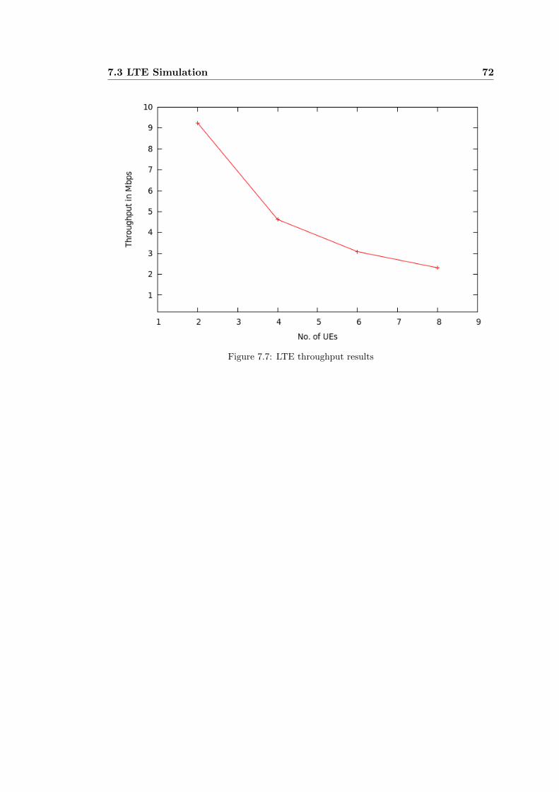
7.3 LTE Simulation 72
Figure 7.7: LTE throughput results
Chapter 8
Conclusion and Future Work
The high demand of broadband wireless access influences researchers and R&D com-
panies to create new wireless technologies and architecture that offer high data rates,
efficiency, and mobility support.
WiMAX and LTE are indeed a great invention for the new era. It has tremendous
potential since it is an IP-based broadband wireless access technology that is similar to
WirelessLAN but provides a coverage range and service comparable to existing cellular
technologies.
Mobile users can connect to the Internet from anywhere in the world and browse
through any site at their own convenience, view television via IPTV while travelling,
listen to online music, perform video streaming, and much more.
The cloud-based network simulator will greatly benefit students, researchers, and engi-
neers to focus on conceptual aspects rather than network simulator configurations. It
utilizes open source tools that requires no license fees compared to those proprietary
GUI-based network simulators.
A network animation for the simulated network would be a good addition for this
project. The user shall be able to play and rewind the data transmission in a simulated
network. Since the cloud-based network simulator uses open source software, it would
be easy for researchers and engineers to implement support for newly approved wireless
74
networks such as WiMAX IEEE 802.11m, LTE-Advanced, WLAN IEEE 802.11n, and
WLAN IEEE 802.11ac.
Overall, this research provides a thorough review and understanding about WiMAX
and LTE protocols particularly the MAC and Physical layers which are responsible for
wireless data transmission. The outcome of this thesis provides a strong foundation for
future work on cloud-based network simulator for WiMAX and LTE technology.
Bibliography
[1] Information Sciences Institute, The Network Simulator, http://www.isi.edu/
nsnam/ns/, June 2004
[2] The ns-3 network simulator, retrieved from http://www.nsnam.org/, September
2011
[3] The SSF Research Network, retrieved from http://ssfnet.org/, September 2011
[4] OMNET++, retrieved from http://www.omnetpp.org/, September 2011
[5] J-Sim, retrieved from http://sites.google.com/site/jsimofficial/, September 2011
[6] OPNET simulator, retrieved from http://www.opnet.com/, September 2011
[7] QualNet, retrieved from http://www.scalable-networks.com/products/, September
2011
[8] Garroppo, R.G.; Giordano, S.; Iacono, D.; , “Experimental and Simulation Study
of a WiMAX System in the Sea Port Scenario,” Communications, 2009. ICC ’09.
IEEE International Conference on , vol., no., pp.1-5, 14-18 June 2009
[9] El-Shinnawy, A.H.; Nassar, A.M.; Badawi, A.H.; , “A switched scheduling algo-
rithm for congestion relief in WiMAX wireless networks,” Computer Engineering
Conference (ICENCO), 2010 International , vol., no., pp.34-39, 27-28 Dec. 2010
[10] Pareit, Daan; Petrov, Viktor; Lannoo, Bart; Tanghe, Emmeric; Joseph, Wout;
Moerman, Ingrid; Demeester, Piet; Martens, Luc; , “A Throughput Analysis at
the MAC Layer of Mobile WiMAX,” Wireless Communications and Networking
Conference (WCNC), 2010 IEEE , vol., no., pp.1-6, 18-21 April 2010

BIBLIOGRAPHY 76
[11] Martin-Sacristan, D.; Cabrejas, J.; Calabuig, D.; Monserrat, J.F.; , “MAC Layer
Performance of Different Channel Estimation Techniques in UTRAN LTE Down-
link,” Vehicular Technology Conference, 2009. VTC Spring 2009. IEEE 69th , vol.,
no., pp.1-5, 26-29 April 2009
[12] 3GPP R1-072261, LTE Performance Evaluation-Uplink Summary, May 2007
[13] 3GPP R1-072578, Summary of Downlink Performance Evaluation, May 2007
[14] Torad, M.; El Qassas, A.; Al Henawi, H.; , “Comparison between LTE and WiMAX
based on system level simulation using OPNET modeler (release 16),” National
Radio Science Conference (NRSC), 2011 28th , vol., no., pp.1-9, 26-28 April 2011
[15] Farooq J., Turletti T., “An IEEE 802.16 WiMAX Module for the NS-3 Simulator”,
2009
[16] LTE Manual, retrieved from http://www.nsnam.org/docs/release/3.10/manual/
html/lte, September 2011
[17] Addie R., Yu P., Zukerman M., “Netml: networking networks”, June 2011
[18] Fatseas D. , Addie R., “Layered Design of Mobile Backhaul Networks”, June 2011
[19] WiMAX Forum White Paper, Industry Research Report, www.wimaxforum.org
May 2011
[20] Carl Eklund, Roger B. Marks, Kenneth L. Stanwood and Stanley Wang, Sum-
mary on IEEE Standard 802.16 - A Technical Overview of the WirelessMANTMAir
Interface for Broadband Wireless Access, June 2002
[21] IEEE 802.16-2004, IEEE Standard for Local and metropolitan area networks Part
16: Air Interface for Fixed Broadband Wireless Access Systems, October 2004
[22] Loutfi Nuaymi, WiMAX: Technology for Broadband Wireless Access, John Wiley
& Sons, Ltd., 2007
[23] Hassan Yaghoobi, Scalable OFDMA Physical Layer in IEEE 802.16 WirelessMAN,
2006
[24] IEEE 802.16-2009, IEEE Standard for Local and metropolitan area networks Part
16: Air Interface for Fixed and Broadband Wireless Access Systems, May 2009
BIBLIOGRAPHY 77
[25] IEEE, Overview of IEEE P802.16m Technology And Candidate RIT For IMTAd-
vanced, January 2010
[26] WiMAX Forum White Paper, Mobile WiMAX Part I: A Technical Overview and
Performance Evaluation, August 2006
[27] WiMAX Forum White Paper, Mobile WiMAX Part II: A Comparative Analysis,
May 2006
[28] Dieter Eberle, LTE vs. WiMAX 4th generation telecommunication networks, 2010
[29] Sang-Wook Kwon and Dong-Ho Cho, CDMA Code-Based Bandwidth Request
Mechanism in IEEE 802.16j Mobile Multi-Hop Relay (MMR) Systems, September
2009
[30] M. Allman, Transmission Control Protocol, retrieved from http://www.ietf.org/
rfc/rfc793.txt, September 1981
[31] J. Postel, User Datagram Protocol, retrieved from http://www.ietf.org/rfc/
rfc0768.txt, August 1980
[32] IEEE 802.16-2009, IEEE Standard for Local and metropolitan area networks, Part
16: Air Interface for Broadband Wireless Access Systems, February 2008
[33] S. Madanapalli, S. Park, RFC 5948, Transmission of IPv4 Packets over the IP
Convergence Sublayer of IEEE 802.16, August 2010
[34] R. Dias, J. Leite, R. Amorim, Analysis of HARQ in WiMAX Networks Considering
Imperfect Channel Estimation, 2010
[35] 3rd Generation Partnership Project (3GPP), retrieved from http://www.3gpp.
org/, September 2011
[36] D. Bourse, R. Tafazolli, Beyond 3G/4G Radio Access Technologies (RATs) and
Standards Roadmaps, 2007
[37] 3GPP TS 36.300: “Evolved Universal Terrestrial Radio Access (E-UTRA) and
Evolved Universal Terrestrial Radio Access (E-UTRAN); Overall description”, De-
cember 2008
BIBLIOGRAPHY 78
[38] 3GPP TS 36.323: “Evolved Universal Terrestrial Radio Access (E-UTRA); Packet
Data Convergence Protocol (PDCP) specification”, December 2008
[39] Motorola White Paper, Driving 4G: WiMAX & LTE, retrieved from www.
motorola.com, 2007
[40] Moray Rumney, Agilent Measurement Journal, “3GPP LTE: Introducing Single-
Carrier FDMA”, January 2008
[41] 3GPP TS 36.321: “Evolved Universal Terrestrial Radio Access (E-UTRA);
Medium Acces Control (MAC) protocol specification”, December 2008
[42] Freescale Semiconductor White Paper, Long Term Evolution Protocol Overview,
October 2008
[43] R. G. Addie, “NetML v4.0 An online environment for access and sharing of
network data and software for network analysis and design, Tech. Rep. SC-MC-
1001, University of Southern Queensland, 2010
[44] Sim Script, retrieved from http://www.simscript.com/, September 2011
[45] WiMAX Deployments, retrieved from http://www.wimaxmaps.org/, October 2011
[46] LTE Deployments, retrieved from http://ltemaps.org/, October 2011

Appendix A
Source Code
XSL Code:
<?xml version="1.0" encoding="UTF-8" ?>
<xsl:stylesheet version="1.0" xmlns:xsl="http://www.w3.org/1999/XSL/Transform">
<xsl:output method="text" encoding="utf-8"/>
<xsl:template match="/">
// project: Cloud-based simulator
// author: Gerson Bacor
#include "ns3/core-module.h"
#include "ns3/network-module.h"
#include "ns3/applications-module.h"
#include "ns3/mobility-module.h"
#include "ns3/config-store-module.h"
#include "ns3/wimax-module.h"
#include "ns3/lte-module.h"
#include "ns3/internet-module.h"
#include "ns3/global-route-manager.h"
#include <iostream>
#include <string>
#include <sstream>
#define MAX_NUM_NODES 20
<xsl:for-each select="network/technology">
#define <xsl:value-of select="name"/>
</xsl:for-each>
#if defined WIMAX

80
NS_LOG_COMPONENT_DEFINE ("NetML_WiMAX_Simulation");
#elif defined LTE
NS_LOG_COMPONENT_DEFINE ("NetML_LTE_Simulation");
#endif
using namespace ns3;
// A structure for network nodes. It could be a basestation or subscriber station.
typedef struct _NetworkNode_t
{
std::string name;
int xposition;
int yposition;
int index;
} NetworkNode_t;
// A structure for network links.
typedef struct _NetworkLink_t
{
std::string name;
std::string origin;
std::string destination;
std::string serviceFlow;
std::string modulationCodingRate;
} NetworkLink_t;
// A structure for traffic streams.
typedef struct _TrafficStream_t
{
std::string name;
std::string origin;
std::string destination;
std::string protocol;
int rate;
int packetSize;
double interval;
} TrafficStream_t;
// A structure for network simulation model.
typedef struct _SimulationModel_t
{
int type;
int trafficStreamIndex;
int duration;
int snrSS;
int snrBS;
bool generateLayer2Log;
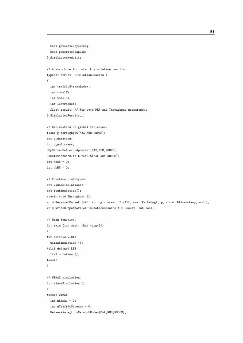
81
bool generateLayer3Log;
bool generatePcapLog;
} SimulationModel_t;
// A structure for network simulation results.
typedef struct _SimulationResults_t
{
int trafficStreamIndex;
int totalTx;
int totalRx;
int lostPacket;
float result; // For both PER and Throughput measurement
} SimulationResults_t;
// Declaration of global variables.
float g_throughput[MAX_NUM_NODES];
int g_duration;
int g_noStreams;
UdpServerHelper udpServer[MAX_NUM_NODES];
SimulationResults_t result[MAX_NUM_NODES];
int nbSS = 0;
int nbBS = 0;
// Function prototypes.
int wimaxSimulation();
int lteSimulation();
static void Throughput ();
void ReceivedPacket (std::string context, Ptr<const Packet> p, const Address& addr);
void writeOutputToFile(SimulationResults_t * result, int len);
// Main function.
int main (int argc, char *argv[])
{
#if defined WIMAX
wimaxSimulation ();
#elif defined LTE
lteSimulation ();
#endif
}
// WiMAX simulation.
int wimaxSimulation ()
{
#ifdef WIMAX
int nLinks = 0;
int nTrafficStreams = 0;
NetworkNode_t bsNetworkNodes[MAX_NUM_NODES];
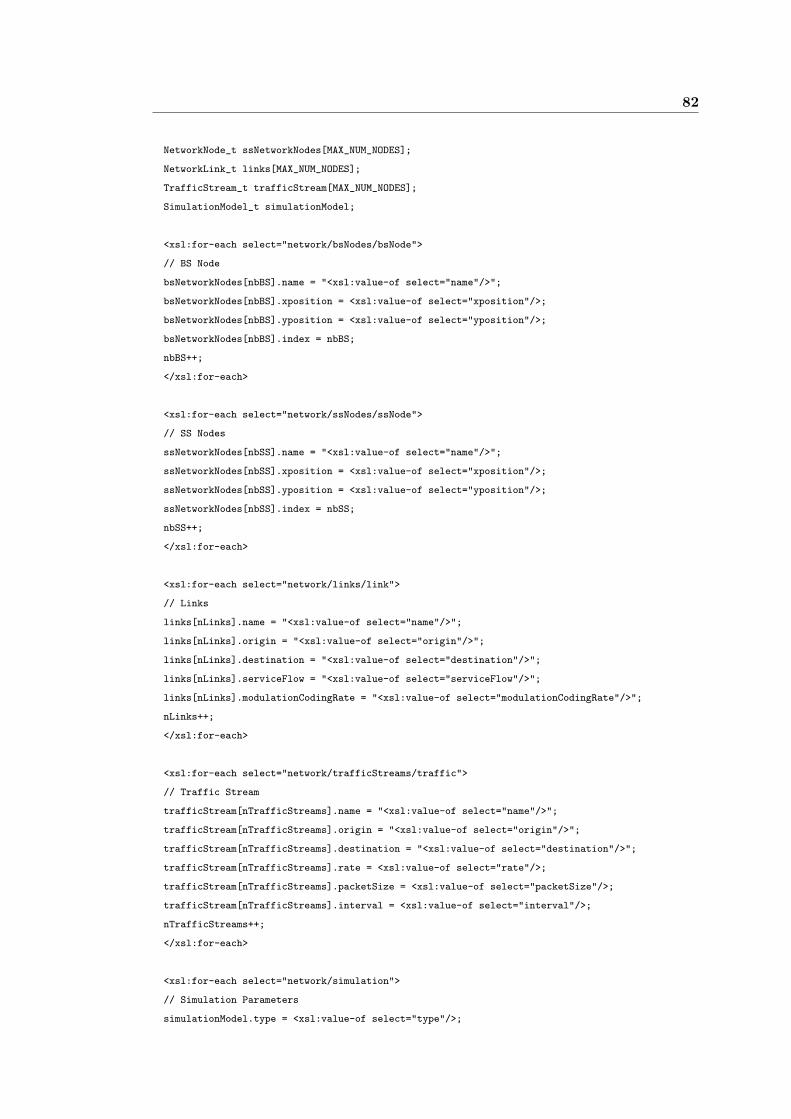
82
NetworkNode_t ssNetworkNodes[MAX_NUM_NODES];
NetworkLink_t links[MAX_NUM_NODES];
TrafficStream_t trafficStream[MAX_NUM_NODES];
SimulationModel_t simulationModel;
<xsl:for-each select="network/bsNodes/bsNode">
// BS Node
bsNetworkNodes[nbBS].name = "<xsl:value-of select="name"/>";
bsNetworkNodes[nbBS].xposition = <xsl:value-of select="xposition"/>;
bsNetworkNodes[nbBS].yposition = <xsl:value-of select="yposition"/>;
bsNetworkNodes[nbBS].index = nbBS;
nbBS++;
</xsl:for-each>
<xsl:for-each select="network/ssNodes/ssNode">
// SS Nodes
ssNetworkNodes[nbSS].name = "<xsl:value-of select="name"/>";
ssNetworkNodes[nbSS].xposition = <xsl:value-of select="xposition"/>;
ssNetworkNodes[nbSS].yposition = <xsl:value-of select="yposition"/>;
ssNetworkNodes[nbSS].index = nbSS;
nbSS++;
</xsl:for-each>
<xsl:for-each select="network/links/link">
// Links
links[nLinks].name = "<xsl:value-of select="name"/>";
links[nLinks].origin = "<xsl:value-of select="origin"/>";
links[nLinks].destination = "<xsl:value-of select="destination"/>";
links[nLinks].serviceFlow = "<xsl:value-of select="serviceFlow"/>";
links[nLinks].modulationCodingRate = "<xsl:value-of select="modulationCodingRate"/>";
nLinks++;
</xsl:for-each>
<xsl:for-each select="network/trafficStreams/traffic">
// Traffic Stream
trafficStream[nTrafficStreams].name = "<xsl:value-of select="name"/>";
trafficStream[nTrafficStreams].origin = "<xsl:value-of select="origin"/>";
trafficStream[nTrafficStreams].destination = "<xsl:value-of select="destination"/>";
trafficStream[nTrafficStreams].rate = <xsl:value-of select="rate"/>;
trafficStream[nTrafficStreams].packetSize = <xsl:value-of select="packetSize"/>;
trafficStream[nTrafficStreams].interval = <xsl:value-of select="interval"/>;
nTrafficStreams++;
</xsl:for-each>
<xsl:for-each select="network/simulation">
// Simulation Parameters
simulationModel.type = <xsl:value-of select="type"/>;
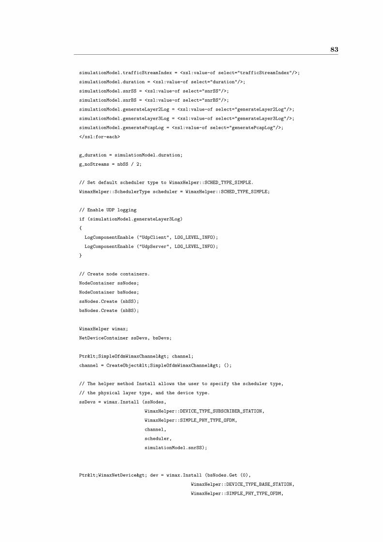
83
simulationModel.trafficStreamIndex = <xsl:value-of select="trafficStreamIndex"/>;
simulationModel.duration = <xsl:value-of select="duration"/>;
simulationModel.snrSS = <xsl:value-of select="snrSS"/>;
simulationModel.snrBS = <xsl:value-of select="snrBS"/>;
simulationModel.generateLayer2Log = <xsl:value-of select="generateLayer2Log"/>;
simulationModel.generateLayer3Log = <xsl:value-of select="generateLayer3Log"/>;
simulationModel.generatePcapLog = <xsl:value-of select="generatePcapLog"/>;
</xsl:for-each>
g_duration = simulationModel.duration;
g_noStreams = nbSS / 2;
// Set default scheduler type to WimaxHelper::SCHED_TYPE_SIMPLE.
WimaxHelper::SchedulerType scheduler = WimaxHelper::SCHED_TYPE_SIMPLE;
// Enable UDP logging
if (simulationModel.generateLayer3Log)
{
LogComponentEnable ("UdpClient", LOG_LEVEL_INFO);
LogComponentEnable ("UdpServer", LOG_LEVEL_INFO);
}
// Create node containers.
NodeContainer ssNodes;
NodeContainer bsNodes;
ssNodes.Create (nbSS);
bsNodes.Create (nbBS);
WimaxHelper wimax;
NetDeviceContainer ssDevs, bsDevs;
Ptr<SimpleOfdmWimaxChannel> channel;
channel = CreateObject<SimpleOfdmWimaxChannel> ();
// The helper method Install allows the user to specify the scheduler type,
// the physical layer type, and the device type.
ssDevs = wimax.Install (ssNodes,
WimaxHelper::DEVICE_TYPE_SUBSCRIBER_STATION,
WimaxHelper::SIMPLE_PHY_TYPE_OFDM,
channel,
scheduler,
simulationModel.snrSS);
Ptr<WimaxNetDevice> dev = wimax.Install (bsNodes.Get (0),
WimaxHelper::DEVICE_TYPE_BASE_STATION,
WimaxHelper::SIMPLE_PHY_TYPE_OFDM,
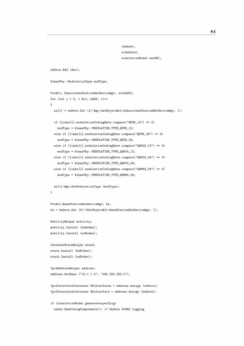
84
channel,
scheduler,
simulationModel.snrBS);
bsDevs.Add (dev);
WimaxPhy::ModulationType modType;
Ptr< SubscriberStationNetDevice> ss[nbSS];
for (int i = 0; i < nbSS; i++)
{
ss[i] = ssDevs.Get (i)->GetObject<SubscriberStationNetDevice> ();
if (links[i].modulationCodingRate.compare("QPSK_12") == 0)
modType = WimaxPhy::MODULATION_TYPE_QPSK_12;
else if (links[i].modulationCodingRate.compare("QPSK_34") == 0)
modType = WimaxPhy::MODULATION_TYPE_QPSK_34;
else if (links[i].modulationCodingRate.compare("QAM16_12") == 0)
modType = WimaxPhy::MODULATION_TYPE_QAM16_12;
else if (links[i].modulationCodingRate.compare("QAM16_34") == 0)
modType = WimaxPhy::MODULATION_TYPE_QAM16_34;
else if (links[i].modulationCodingRate.compare("QAM64_34") == 0)
modType = WimaxPhy::MODULATION_TYPE_QAM64_34;
ss[i]->SetModulationType (modType);
}
Ptr<BaseStationNetDevice> bs;
bs = bsDevs.Get (0)->GetObject<BaseStationNetDevice> ();
MobilityHelper mobility;
mobility.Install (bsNodes);
mobility.Install (ssNodes);
InternetStackHelper stack;
stack.Install (bsNodes);
stack.Install (ssNodes);
Ipv4AddressHelper address;
address.SetBase ("10.1.1.0", "255.255.255.0");
Ipv4InterfaceContainer SSinterfaces = address.Assign (ssDevs);
Ipv4InterfaceContainer BSinterface = address.Assign (bsDevs);
if (simulationModel.generateLayer2Log)
wimax.EnableLogComponents(); // Enable WiMAX logging

85
int src = 0, dst = 0;
for (int j = 0; j < nbSS; j++)
{
if (trafficStream[simulationModel.trafficStreamIndex].origin.compare(ssNetworkNodes[j].name) == 0)
{
src = ssNetworkNodes[j].index;
break;
}
}
for (int j = 0; j < nbSS; j++)
{
if (trafficStream[simulationModel.trafficStreamIndex].destination.compare(ssNetworkNodes[j].name) == 0)
{
dst = ssNetworkNodes[j].index;
break;
}
}
if (simulationModel.type == 0) // Throughput Test
{
// Creates application containers. Application containers holds a vector of ns3::Application pointers.
ApplicationContainer serverApps[nbSS / 2];
UdpClientHelper udpClient[nbSS / 2];
ApplicationContainer clientApps[nbSS / 2];
for (int i = 0; i < nbSS / 2; i++)
{
udpServer[i] = UdpServerHelper (100 + (i * 10));
serverApps[i] = udpServer[i].Install (ssNodes.Get (i));
serverApps[i].Start (Seconds (1));
serverApps[i].Stop (Seconds (simulationModel.duration));
udpClient[i] = UdpClientHelper (SSinterfaces.GetAddress (i), 100 + (i * 10));
udpClient[i].SetAttribute ("MaxPackets", UintegerValue (10000000));
udpClient[i].SetAttribute ("Interval", TimeValue (Seconds(trafficStream[0].interval)));
udpClient[i].SetAttribute ("PacketSize", UintegerValue (trafficStream[0].packetSize));
clientApps[i] = udpClient[i].Install (ssNodes.Get (i + (nbSS / 2)));
clientApps[i].Start (Seconds (1));
clientApps[i].Stop (Seconds (simulationModel.duration));
}
Simulator::Stop (Seconds (simulationModel.duration + 0.1));
}
else if (simulationModel.type == 1) // ICMP:Echo or Ping Test
{
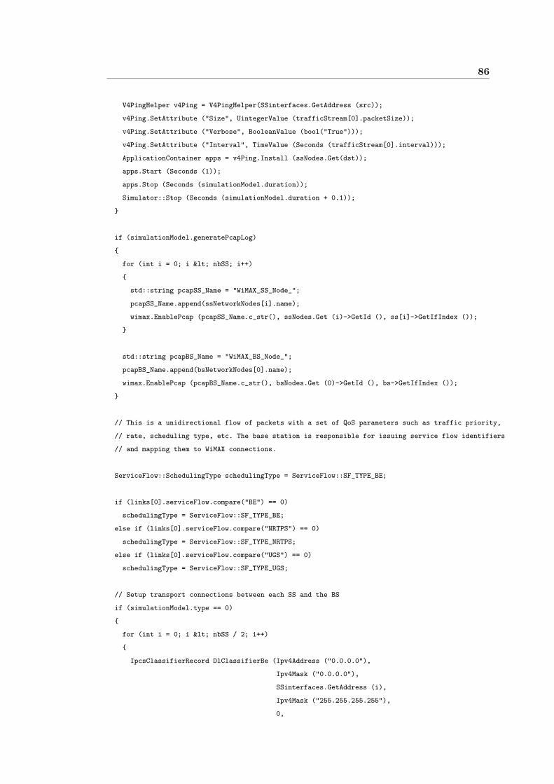
86
V4PingHelper v4Ping = V4PingHelper(SSinterfaces.GetAddress (src));
v4Ping.SetAttribute ("Size", UintegerValue (trafficStream[0].packetSize));
v4Ping.SetAttribute ("Verbose", BooleanValue (bool("True")));
v4Ping.SetAttribute ("Interval", TimeValue (Seconds (trafficStream[0].interval)));
ApplicationContainer apps = v4Ping.Install (ssNodes.Get(dst));
apps.Start (Seconds (1));
apps.Stop (Seconds (simulationModel.duration));
Simulator::Stop (Seconds (simulationModel.duration + 0.1));
}
if (simulationModel.generatePcapLog)
{
for (int i = 0; i < nbSS; i++)
{
std::string pcapSS_Name = "WiMAX_SS_Node_";
pcapSS_Name.append(ssNetworkNodes[i].name);
wimax.EnablePcap (pcapSS_Name.c_str(), ssNodes.Get (i)->GetId (), ss[i]->GetIfIndex ());
}
std::string pcapBS_Name = "WiMAX_BS_Node_";
pcapBS_Name.append(bsNetworkNodes[0].name);
wimax.EnablePcap (pcapBS_Name.c_str(), bsNodes.Get (0)->GetId (), bs->GetIfIndex ());
}
// This is a unidirectional flow of packets with a set of QoS parameters such as traffic priority,
// rate, scheduling type, etc. The base station is responsible for issuing service flow identifiers
// and mapping them to WiMAX connections.
ServiceFlow::SchedulingType schedulingType = ServiceFlow::SF_TYPE_BE;
if (links[0].serviceFlow.compare("BE") == 0)
schedulingType = ServiceFlow::SF_TYPE_BE;
else if (links[0].serviceFlow.compare("NRTPS") == 0)
schedulingType = ServiceFlow::SF_TYPE_NRTPS;
else if (links[0].serviceFlow.compare("UGS") == 0)
schedulingType = ServiceFlow::SF_TYPE_UGS;
// Setup transport connections between each SS and the BS
if (simulationModel.type == 0)
{
for (int i = 0; i < nbSS / 2; i++)
{
IpcsClassifierRecord DlClassifierBe (Ipv4Address ("0.0.0.0"),
Ipv4Mask ("0.0.0.0"),
SSinterfaces.GetAddress (i),
Ipv4Mask ("255.255.255.255"),
0,
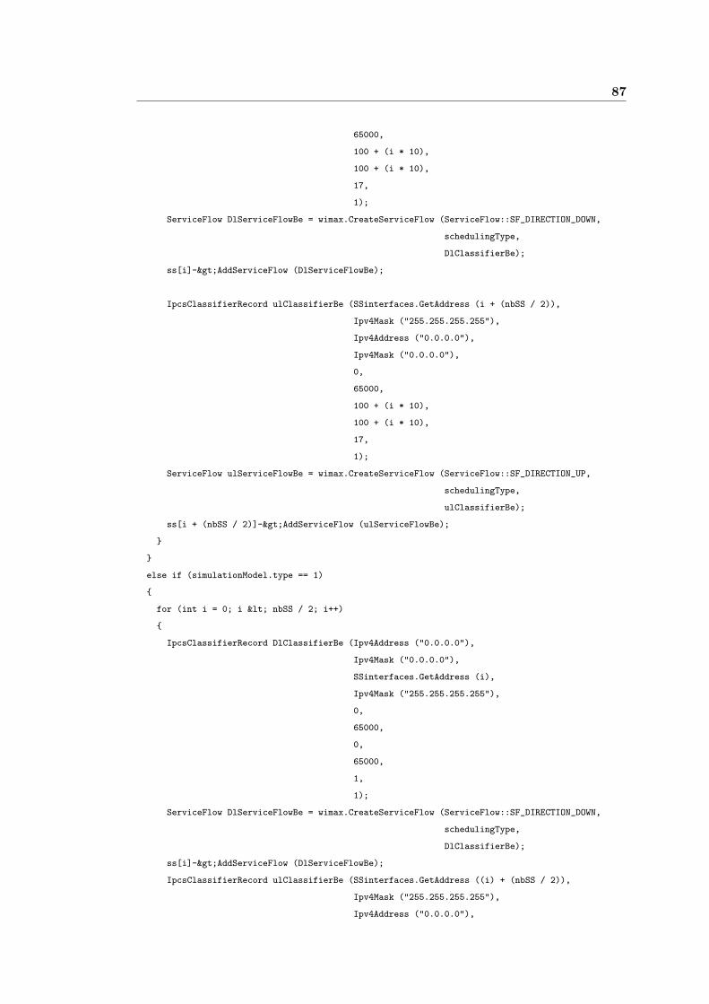
87
65000,
100 + (i * 10),
100 + (i * 10),
17,
1);
ServiceFlow DlServiceFlowBe = wimax.CreateServiceFlow (ServiceFlow::SF_DIRECTION_DOWN,
schedulingType,
DlClassifierBe);
ss[i]->AddServiceFlow (DlServiceFlowBe);
IpcsClassifierRecord ulClassifierBe (SSinterfaces.GetAddress (i + (nbSS / 2)),
Ipv4Mask ("255.255.255.255"),
Ipv4Address ("0.0.0.0"),
Ipv4Mask ("0.0.0.0"),
0,
65000,
100 + (i * 10),
100 + (i * 10),
17,
1);
ServiceFlow ulServiceFlowBe = wimax.CreateServiceFlow (ServiceFlow::SF_DIRECTION_UP,
schedulingType,
ulClassifierBe);
ss[i + (nbSS / 2)]->AddServiceFlow (ulServiceFlowBe);
}
}
else if (simulationModel.type == 1)
{
for (int i = 0; i < nbSS / 2; i++)
{
IpcsClassifierRecord DlClassifierBe (Ipv4Address ("0.0.0.0"),
Ipv4Mask ("0.0.0.0"),
SSinterfaces.GetAddress (i),
Ipv4Mask ("255.255.255.255"),
0,
65000,
0,
65000,
1,
1);
ServiceFlow DlServiceFlowBe = wimax.CreateServiceFlow (ServiceFlow::SF_DIRECTION_DOWN,
schedulingType,
DlClassifierBe);
ss[i]->AddServiceFlow (DlServiceFlowBe);
IpcsClassifierRecord ulClassifierBe (SSinterfaces.GetAddress ((i) + (nbSS / 2)),
Ipv4Mask ("255.255.255.255"),
Ipv4Address ("0.0.0.0"),
88
Ipv4Mask ("0.0.0.0"),
0,
65000,
0,
65000,
1,
1);
ServiceFlow ulServiceFlowBe = wimax.CreateServiceFlow (ServiceFlow::SF_DIRECTION_UP,
schedulingType,
ulClassifierBe);
ss[i + (nbSS / 2)]->AddServiceFlow (ulServiceFlowBe);
}
}
if (simulationModel.type == 0)
{
std::string context4 = "/NodeList/*/ApplicationList/*/$ns3::UdpServer/Rx";
Config::Connect (context4, MakeCallback(&ReceivedPacket));
Time time = Simulator::Now ();
Simulator::Schedule (Seconds (g_duration), &Throughput);
}
NS_LOG_INFO ("Starting NetML-NS3 simulation.....");
Simulator::Run ();
// Write the results in to a file.
writeOutputToFile(result, nbSS / 2);
for (int i = 0; i <nbSS; i++)
ss[i] = 0;
bs = 0;
Simulator::Destroy ();
NS_LOG_INFO ("Done.");
#endif
return 0;
}
int lteSimulation ()
{
#ifdef LTE
int nbUE = 0;
int nbeNB = 0;
int nLinks = 0;

89
int nTrafficStreams = 0;
NetworkNode_t bsNetworkNodes[MAX_NUM_NODES];
NetworkNode_t ssNetworkNodes[MAX_NUM_NODES];
NetworkLink_t links[MAX_NUM_NODES];
TrafficStream_t trafficStream[MAX_NUM_NODES];
SimulationModel_t simulationModel;
<xsl:for-each select="network/bsNodes/bsNode">
// eNB Nodes
bsNetworkNodes[nbeNB].name = "<xsl:value-of select="name"/>";
bsNetworkNodes[nbeNB].xposition = <xsl:value-of select="xposition"/>;
bsNetworkNodes[nbeNB].yposition = <xsl:value-of select="yposition"/>;
bsNetworkNodes[nbeNB].index = nbeNB;
nbeNB++;
</xsl:for-each>
<xsl:for-each select="network/ssNodes/ssNode">
// UE Nodes
ssNetworkNodes[nbUE].name = "<xsl:value-of select="name"/>";
ssNetworkNodes[nbUE].xposition = <xsl:value-of select="xposition"/>;
ssNetworkNodes[nbUE].yposition = <xsl:value-of select="yposition"/>;
ssNetworkNodes[nbUE].index = nbUE;
nbUE++;
</xsl:for-each>
<xsl:for-each select="network/links/link">
// Links
links[nLinks].name = "<xsl:value-of select="name"/>";
links[nLinks].origin = "<xsl:value-of select="origin"/>";
links[nLinks].destination = "<xsl:value-of select="destination"/>";
links[nLinks].serviceFlow = "<xsl:value-of select="serviceFlow"/>";
links[nLinks].modulationCodingRate = "<xsl:value-of select="modulationCodingRate"/>";
nLinks++;
</xsl:for-each>
<xsl:for-each select="network/trafficStreams/traffic">
// Traffic Stream
trafficStream[nTrafficStreams].name = "<xsl:value-of select="name"/>";
trafficStream[nTrafficStreams].origin = "<xsl:value-of select="origin"/>";
trafficStream[nTrafficStreams].destination = "<xsl:value-of select="destination"/>";
trafficStream[nTrafficStreams].rate = <xsl:value-of select="rate"/>;
trafficStream[nTrafficStreams].packetSize = <xsl:value-of select="packetSize"/>;
trafficStream[nTrafficStreams].interval = <xsl:value-of select="interval"/>;
nTrafficStreams++;
</xsl:for-each>

90
<xsl:for-each select="network/simulation">
// Simulation Parameters
simulationModel.type = <xsl:value-of select="type"/>;
simulationModel.trafficStreamIndex = <xsl:value-of select="trafficStreamIndex"/>;
simulationModel.duration = <xsl:value-of select="duration"/>;
simulationModel.snrSS = <xsl:value-of select="snrSS"/>;
simulationModel.snrBS = <xsl:value-of select="snrBS"/>;
simulationModel.generateLayer2Log = <xsl:value-of select="generateLayer2Log"/>;
simulationModel.generateLayer3Log = <xsl:value-of select="generateLayer3Log"/>;
simulationModel.generatePcapLog = <xsl:value-of select="generatePcapLog"/>;
</xsl:for-each>
g_duration = simulationModel.duration;
g_noStreams = nbUE / 2;
LteHelper lte;
//lte.EnableLogComponents ();
LogComponentEnable ("UdpClient", LOG_LEVEL_INFO);
LogComponentEnable ("UdpServer", LOG_LEVEL_INFO);
// Create node container and lte nodes.
NodeContainer ueNodes;
NodeContainer enbNodes;
ueNodes.Create (nbUE);
enbNodes.Create (1);
// Create device container and install device to node.
NetDeviceContainer ueDevs, enbDevs;
ueDevs = lte.Install (ueNodes, LteHelper::DEVICE_TYPE_USER_EQUIPMENT);
enbDevs = lte.Install (enbNodes, LteHelper::DEVICE_TYPE_ENODEB);
// Install internet stacks.
InternetStackHelper stack;
stack.Install (ueNodes);
stack.Install (enbNodes);
Ipv4AddressHelper address;
address.SetBase ("10.1.1.0", "255.255.255.0");
Ipv4InterfaceContainer UEinterfaces = address.Assign (ueDevs);
Ipv4InterfaceContainer ENBinterface = address.Assign (enbDevs);
// Manage LTE net devices.
Ptr<EnbNetDevice> enb;
enb = enbDevs.Get (0)->GetObject<EnbNetDevice> ();
Ptr<UeNetDevice> ue[nbUE];
for (int i = 0; i < nbUE; i++)

91
{
ue[i] = ueDevs.Get (i)->GetObject<UeNetDevice> ();
lte.RegisterUeToTheEnb (ue[i], enb);
}
// Configure downlink and uplink channels.
// Define a list of sub channels for the downlink
std::vector<int> dlSubChannels;
for (int i = 0; i < 25; i++)
dlSubChannels.push_back (i);
// Define a list of sub channels for the uplink
std::vector<int> ulSubChannels;
for (int i = 50; i < 100; i++)
ulSubChannels.push_back (i);
enb->GetPhy ()->SetDownlinkSubChannels (dlSubChannels);
enb->GetPhy ()->SetUplinkSubChannels (ulSubChannels);
for (int i = 0; i < nbUE; i++)
{
ue[i]->GetPhy ()->SetDownlinkSubChannels (dlSubChannels);
ue[i]->GetPhy ()->SetUplinkSubChannels (ulSubChannels);
}
// Configure mobility.
Ptr<ConstantPositionMobilityModel> enbMobility = CreateObject<ConstantPositionMobilityModel>();
enbMobility->SetPosition (Vector (0.0, 0.0, 0.0));
lte.AddMobility (enb->GetPhy (), enbMobility);
for (int i = 0; i < nbUE; i++)
{
Ptr<ConstantVelocityMobilityModel> ueMobility = CreateObject<ConstantVelocityMobilityModel>();
ueMobility->SetPosition (Vector (30.0, 0.0, 0.0));
ueMobility->SetVelocity (Vector (30.0, 0.0, 0.0));
lte.AddMobility (ue[i]->GetPhy (), ueMobility);
lte.AddDownlinkChannelRealization (enbMobility, ueMobility, ue[i]->GetPhy ());
}
// Create udp applications.
ApplicationContainer serverApp[nbUE];
UdpClientHelper udpClient[nbUE];
ApplicationContainer clientApp[nbUE];
Ptr<RadioBearerInstance> bearer[nbUE];
92
IpcsClassifierRecord * ipcs[nbUE];
for (int i = 0; i < nbUE; i++)
{
udpServer[i] = UdpServerHelper (100);
serverApp[i] = udpServer[i].Install (ueNodes.Get (i));
serverApp[i].Start (Seconds (0));
serverApp[i].Stop (Seconds (simulationModel.duration));
udpClient[i] = UdpClientHelper (UEinterfaces.GetAddress (i), 100);
udpClient[i].SetAttribute ("MaxPackets", UintegerValue (10000000));
udpClient[i].SetAttribute ("Interval", TimeValue (Seconds (trafficStream[0].interval)));
udpClient[i].SetAttribute ("PacketSize", UintegerValue (trafficStream[0].packetSize));
clientApp[i] = udpClient[i].Install (enbNodes.Get (0));
clientApp[i].Start (Seconds (0));
clientApp[i].Stop (Seconds (simulationModel.duration));
bearer[i] = CreateObject<RadioBearerInstance> ();
bearer[i]->SetBearerDirection (RadioBearerInstance::DIRECTION_TYPE_DL);
bearer[i]->SetBearerType (RadioBearerInstance::BEARER_TYPE_DRB);
ipcs[i] = new IpcsClassifierRecord (UEinterfaces.GetAddress (i),
"255.255.255.0",
ENBinterface.GetAddress (0),
"255.255.255.0",
100, 100, 0, 10000, 17, 1);
bearer[i]->SetIpcsClassifierRecord (ipcs[i]);
enb->GetRrcEntity ()->AddDownlinkNgbrBearer (bearer[i]);
}
std::cout << "Starting simulation....." << std::endl;
Simulator::Stop (Seconds (simulationModel.duration + 0.1));
Time time = Simulator::Now ();
Simulator::Schedule (Seconds (g_duration), &Throughput);
Simulator::Run ();
writeOutputToFile(result, g_noStreams);
Simulator::Destroy ();
for (int i = 0; i < nbUE; i++)
{
delete ipcs[i];
}
std::cout << "Done." << std::endl;
93
#endif
return 0;
}
static void Throughput ()
{
for (int i = 0; i < g_noStreams; i++)
{
g_throughput[i] = (((udpServer[i].GetTotalRx() * 8.0) / 1000000) / g_duration);
result[i].trafficStreamIndex = i;
result[i].totalTx = 1;
result[i].totalRx = udpServer[i].GetTotalRx();
result[i].lostPacket = udpServer[i].GetLost();
result[i].result = g_throughput[i];
}
}
void ReceivedPacket (std::string context, Ptr<const Packet> p, const Address& addr)
{
// For debugging purposes.
/*
std::cout << "GetTotalRx_1 " << udpServer[0].GetTotalRx() << std::endl;
std::cout << "GetTotalRx_2 " << udpServer[1].GetTotalRx() << std::endl;
std::cout << "GetReceived_1 " << udpServer[0].GetReceived() << std::endl;
std::cout << "GetReceived_2 " << udpServer[1].GetReceived() << std::endl;
std::cout << "GetLost_1 " << udpServer[0].GetLost() << std::endl;
std::cout << "GetLost_2 " << udpServer[1].GetLost() << std::endl;
*/
}
void writeOutputToFile(SimulationResults_t * result, int size)
{
FILE *p = NULL;
std::string fileName = "NetML_NS3.out";
size_t len = 0;
p = fopen(fileName.c_str(), "w");
if (p == NULL)
{
std::cout << "Error in opening a file -> " << fileName.c_str() << std::endl;
}
// Output file format => trafficStreamIndex:totalTx:totalRx:lostPacket:result
std::string out;
std::stringstream stream;
94
for (int x = 0; x < size; x++)
{
stream << result[x].trafficStreamIndex << ’:’;
stream << result[x].totalTx << ’:’;
stream << result[x].totalRx << ’:’;
stream << result[x].lostPacket << ’:’;
stream << result[x].result << ’\n’;
}
out = stream.str();
std::cout << out.c_str();
len = strlen(out.c_str());
fwrite(out.c_str(), len, 1, p);
fclose(p);
}
</xsl:template>
</xsl:stylesheet>
Python Code:
from xml.dom.minidom import parse
import re
doc = parse("wimax_lte.xml")
# Create the main <results> element
main = doc.createElement("resutls")
# open file
f = open ("NetML_NS3.out","r")
data = f.readline().rstrip()
while (data):
x = data.split(’:’)
node1 = doc.createElement("result")
main.appendChild(node1)
node2 = doc.createElement("trafficStreamIndex")
node1.appendChild(node2)
str = x[0]
val = doc.createTextNode(str)

95
node2.appendChild(val)
node2 = doc.createElement("totalTx")
node1.appendChild(node2)
str = x[1]
val = doc.createTextNode(str)
node2.appendChild(val)
node2 = doc.createElement("totalRx")
node1.appendChild(node2)
str = x[2]
val = doc.createTextNode(str)
node2.appendChild(val)
node2 = doc.createElement("lostPacket")
node1.appendChild(node2)
str = x[3]
val = doc.createTextNode(str)
node2.appendChild(val)
node2 = doc.createElement("result")
node1.appendChild(node2)
str = x[4]
val = doc.createTextNode(str)
node2.appendChild(val)
data = f.readline().rstrip()
doc.childNodes[0].appendChild(main)
input_string = doc.toprettyxml()
# Workaround for toprettyxml whitespace problem
fix = re.compile(r’((?<=>)(\n[\t]*)(?=[^<\t]))|(?<=[^>\t])(\n[\t]*)(?=<)’)
fixed_output = re.sub(fix, ’’, input_string)
print fixed_output
# Close the file
f.close()
Recommended