© Copyright 2002HPC, Inc.
Schiller Park, Illinois • 60176 • U.S.A.
Blitz1 2 0 0 C M B
CO
DE
MIL
LIN
GK
EY
MA
CH
INE
™

B L I T Z ™
1200CMB1
INTRODUCTIONThe Blitz™ is HPC’s upgraded version of the 1200CM Code Machine. It works exactly the same as the 1200CM, buthas several added features. Both the depth and spacing shafts have fewer threads per inch, which means thatsubstantially less revolutions are needed to achieve the full range of travel. Plus, the Blitz™ Code Machine is equippedwith HPC’s Softie™ deburring brush with a safety shield.
This revolutionary code milling machine has made all others obsolete and is now the “Standard of the Industry”. TheBlitz™ is very simple to use and extremely versatile. It cuts by actual manufacturer’s depths and spaces. There is noneed to convert to micrometer readings. With its rotating cutter head, the Blitz™ can cut Medeco® keys (includingBiaxial™).
This machine cuts accurate keys by code quickly and easily. The ease of changing from one manufacturer’sspecifications to another’s is so simple, it is unparalleled. Even radically different changes can be set up in 10 to 30seconds without wasting any key blanks.
This dramatic code cutting advancement is made possible through the use of code cards, which are inserted in thecode machine. These cards have depth and space indicators, plus all the pertinent information such as cutter, jaw,code series, blanks and any special information you may need. Quite often, just replacing a code card is all that isrequired when making a change. Depth and space adjustments are never required in changing from one manufacturerto another. The Blitz™ Code Machine is a must for those who create master key systems or do code work.
A fully illustrated, step-by-step set of instructions is contained in the following pages. Please, be sure to spend sometime reading and understanding all the steps thoroughly - so that NONE of the unique capabilities of this unusualmachine is overlooked.
You will find, that cutting keys to dimensions more exact than the lock manufacturer’s themselves produce, isaccomplished with extraordinary ease - on this machine!
For those people, who currently own a 1200CM style key machine and want to upgrade to a Blitz™, HPC has justsuch a conversion program. Please contact your Authorized HPC Distributor for details on this process.
PLEASE NOTE:• This manual is for all motorized 1200 series code machines. These include all models of the
1200CMB (ACDC, DC, 240V etc.)• All usage, adjustment and maintenance functions are the same on all models.• All pictures shown are of model 1200CMB.
*Medeco® is a registered trademark of Medeco Security Locks, Inc.
112503 36CMB-000-PR
B L I T Z ™
1200CMB2
HIGH QUALITY CARBIDE
HP
C, I
NC. SCHILLER PARK, IL
US
A
THIS SIDE OUT
ROTATI
ON
CW-128CHIGH QUALITY CARBIDE
HP
C, I
NC. SCHILLER PARK, ILU
SACW-128C
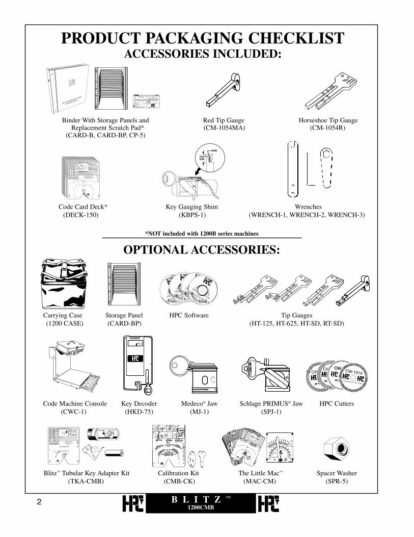
PRODUCT PACKAGING CHECKLISTACCESSORIES INCLUDED:
*NOT included with 1200B series machines
OPTIONAL ACCESSORIES:
Binder With Storage Panels and Red Tip Gauge Horseshoe Tip GaugeReplacement Scratch Pad* (CM-1054MA) (CM-1054R)
(CARD-B, CARD-BP, CP-5)
Code Card Deck* Key Gauging Shim Wrenches(DECK-150) (KBPS-1) (WRENCH-1, WRENCH-2, WRENCH-3)
Carrying Case Storage Panel HPC Software Tip Gauges(1200 CASE) (CARD-BP) (HT-125, HT-625, HT-SD, RT-SD)
Code Machine Console Key Decoder Medeco® Jaw Schlage PRIMUS® Jaw HPC Cutters(CWC-1) (HKD-75) (MJ-1) (SPJ-1)
Blitz™ Tubular Key Adapter Kit Calibration Kit The Little Mac™ Spacer Washer(TKA-CMB) (CMB-CK) (MAC-CM) (SPR-5)

B L I T Z ™
1200CMB3
INDEXTOPICS SECTION PAGE
Introduction . . . . . . . . . . . . . . . . . . . . . . . . . . . . . . . . . . . . . . . . . . . . . . . . . . . .1
Product Packaging Checklist . . . . . . . . . . . . . . . . . . . . . . . . . . . . . . . . . . . . . . .2
Parts Designation Chart . . . . . . . . . . . . . . . . . . . . . . . . . . . . . . . . . . . . . . . . . . .4
Code Cards . . . . . . . . . . . . . . . . . . . . . . . . . . . . . . . . . . . . . . . . .1.0 . . . . . . . . .5Typical Information . . . . . . . . . . . . . . . . . . . . . . . . . . . . .1.1 . . . . . . . . .6Storage, Use and Care . . . . . . . . . . . . . . . . . . . . . . . . . . .1.2 . . . . . . . . .9Familiarization . . . . . . . . . . . . . . . . . . . . . . . . . . . . . . . .1.3 . . . . . . . .11
Cutters . . . . . . . . . . . . . . . . . . . . . . . . . . . . . . . . . . . . . . . . . . . .2.0 . . . . . . . .15Stock, Optional . . . . . . . . . . . . . . . . . . . . . . . . . . . . . . . .2.1 . . . . . . . .16Changing Cutters . . . . . . . . . . . . . . . . . . . . . . . . . . . . . . .2.2 . . . . . . . .20
Gauging and Holding Keys . . . . . . . . . . . . . . . . . . . . . . . . . . . . .3.0 . . . . . . . .25Shoulder Gauge Safety Switch . . . . . . . . . . . . . . . . . . . .3.1 . . . . . . . .26Key Gauges . . . . . . . . . . . . . . . . . . . . . . . . . . . . . . . . . . .3.2 . . . . . . . .27Standard Gauging: Use of Jaw A . . . . . . . . . . . . . . . . . . .3.3 . . . . . . . .29Standard Gauging: Use of Jaw B . . . . . . . . . . . . . . . . . . .3.4 . . . . . . . .33Red Full Short Tip Stop . . . . . . . . . . . . . . . . . . . . . . . . .3.5 . . . . . . . .37Red Middle Short Tip Stop . . . . . . . . . . . . . . . . . . . . . . .3.6 . . . . . . . .41Black Horseshoe Tip Stop (Short End) . . . . . . . . . . . . . .3.7 . . . . . . . .45Medeco® Jaw . . . . . . . . . . . . . . . . . . . . . . . . . . . . . . . . . .3.8 . . . . . . . .49Black Horseshoe Tip Stop (Full End) . . . . . . . . . . . . . . . .3.9 . . . . . . . .51
Depth and Space Crank Controls . . . . . . . . . . . . . . . . . . . . . . . .4.0 . . . . . . . .55
Cutting the Key . . . . . . . . . . . . . . . . . . . . . . . . . . . . . . . . . . . . . .5.0 . . . . . . . .61
Angle Cut Keys . . . . . . . . . . . . . . . . . . . . . . . . . . . . . . . . . . . . .6.0 . . . . . . . .77Use of Swivel Cutter Head . . . . . . . . . . . . . . . . . . . . . . .6.1 . . . . . . . .78Decoding and Cutting . . . . . . . . . . . . . . . . . . . . . . . . . . .6.2 . . . . . . . .79
Re-calibration of Depth . . . . . . . . . . . . . . . . . . . . . . . . . . . . . . . .7.0 . . . . . . . .95Cutting Too High or Low . . . . . . . . . . . . . . . . . . . . . . . .7.1 . . . . . . . .97
Re-calibration of Space . . . . . . . . . . . . . . . . . . . . . . . . . . . . . . . .8.0 . . . . . . .101Cutting Too Close or Too Far From the Tip . . . . . . . . . . .8.1 . . . . . . .104Cutting Too Close or Too Far From the Shoulder . . . . . . .8.2 . . . . . . .115
Preventive Maintenance, Lubrication,Repairs and Guarantee . . . . . . . . . . . . . . . . . . . . . . . . . . . . . . . .9.0 . . . . . . .127
Exploded Views and Parts Lists . . . . . . . . . . . . . . . . . . . . . . . . .10.0 . . . . . . .131

B L I T Z ™
1200CMB4
Brush Guard
Motor
Belt GuardPivot Pin
Cutter Head Assembly
Wing Nut
HPC Lens
Key Vise
Key Vise Base
Eccentric Shaft
Lateral Crank Assembly
Pivot Arm Shaft
Tip Gauge
Depth Crank BearingDepth Crank Assembly
Shoulder Gauge
Angle Index Pin
Motor Belt
Softie Brush
Brush NutMotor Pulley
Cutter Shaft Nut
Toggle Switch
Cutter
PARTS DESIGNATION CHART FOR THE 1200CMB CODE MACHINE
Easy FlipPivot Arm Assembly
Safety Switch

B L I T Z ™
1200CMB5
1.0CODE CARDS

B L I T Z ™
1200CMB6
CODE CARDS
The correctly positioned depth of cuts is shown in the upper arc.The correct spacing of cuts is shown in the lower arc.

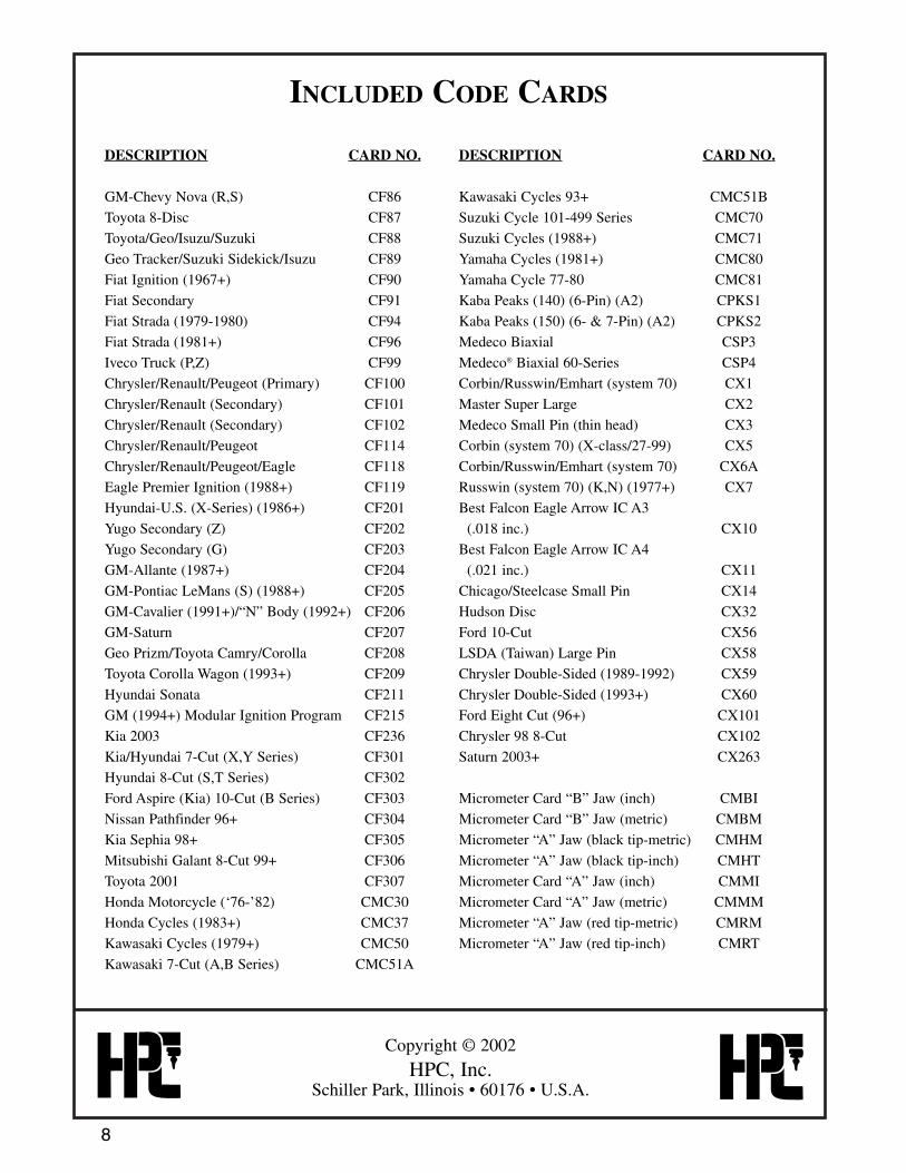
INCLUDED CODE CARDS
7
DESCRIPTION CARD NO.
American Motors (D, E, K, L) C1
Arrow—New Large Pin C2
Arrow (A2)/Best/Falcon/Eagle C3
Briggs & Stratton Disc (Gas Cap) C4
Chicago/Fort Single-Sided Disc C5
Chicago Pin C6
Chrysler Pin (1969+) C10
Corbin Disc C11
Corbin Small Pin C12
Dexter Large Pin (1969+) C16
Eagle Small Pin Long Space C20
Eagle Large Pin C21
Ford 5-Pin Double-Sided (1965+) C24
General Motors Wafer (1936+) C25
Hudson Small Pin C26
Ilco Small Pin C27
Ilco & Lockwood Large Pin C28
Illinois/Timberline Single-Sided Disc C29
American Small Pin C30
Kwikset Large Pin C31
Kwikset Titan C31X
Master Small Pin (7K) C34
Master Standard Large Pin (1K) C35
Medeco Standard (.030 inc.) C36
National Cabinet Single-Sided Disc C37
National Cabinet Small Pin Standard C39
National Large Pin C40
Russwin Large Pin (not system 70) C41
Russwin D&H Pre-System 70 C42
Sargent Large Pin C44
Schlage Large Pin C45
Segal Large Pin C46
Taylor Small Pin C48
Taylor Large Pin C49
Falcon/Weiser Large Pin C50
Welch Large Pin C51
Weslock Large Pin/Vanguard C52
XL Lock Letterbox (X, K Series) C53
Yale Disc C55
Yale Small Pin C56
Yale Large Pin C57
DESCRIPTION CARD NO.
Master Pro Series 2001+ C103A
Dom 2H (44) Double-Sided C104
Dom 2C (17) Single-Sided C105
National Cabinet Lock Letterbox C107
Abus Diskus Rekeyable C112
Lori L10 IC C115
Schlage Everest IC C116
Alfa Flexcore C345
ASSA Twin 6000 CEX1
VW (plain/shoulder side) CF3
Audi/Porsche/VW CF4
Volvo/VW (Gas Cap) CF8
Ford Capri/Fiesta/Jaguar CF11
Merkur (German Ford) (1985-1989) CF13
BMW/Mercedes (11-Wafer) (1975+) CF34
Porsche (911-912) CF36
Datsun/Mazda/Triumph/Jaguar CF40
British Autos & Cycles CF43
Ford Cargo Truck (1986+)/Sterling CF48
Jaguar XJ6 (10-Disc) (1988+) CF49
Volvo/ MG Primary & Secondary CF51
Volvo 240, 740, 760 CF52
Saab (1974+) CF56
Datsun/Subaru/Nissan (F,M,N,W) CF60
Ford/Mazda Truck CF63
Mazda (1970-1980) CF64
Ford/Mercury/Mazda CF65
Datsun/Subaru/GMC/Nissan (8-Disc) CF67
Ford/Mazda MPV Minivan 10-Cut CF68
Honda Ignition (thru ‘76) Series
(2001-4949) CF70
Honda Door/Trunk (thru 1976)
(Series 111111-444444) CF71
Acura (1986+)/Honda (1982+) CF73
Acura (1990+)/Honda (1988+) CF74
Hyundai/Toyota/Isuzu/Mitsubishi CF80
Chevy Luv (B)/Toyota (1969+) CF81
Toyota (unlettered) (1969+) CF82
GM-Chevy/Isuzu/Mitsubishi CF85
INCLUDED CODE CARDS
Copyright © 2002
HPC, Inc.Schiller Park, Illinois • 60176 • U.S.A.
8
DESCRIPTION CARD NO.
GM-Chevy Nova (R,S) CF86
Toyota 8-Disc CF87
Toyota/Geo/Isuzu/Suzuki CF88
Geo Tracker/Suzuki Sidekick/Isuzu CF89
Fiat Ignition (1967+) CF90
Fiat Secondary CF91
Fiat Strada (1979-1980) CF94
Fiat Strada (1981+) CF96
Iveco Truck (P,Z) CF99
Chrysler/Renault/Peugeot (Primary) CF100
Chrysler/Renault (Secondary) CF101
Chrysler/Renault (Secondary) CF102
Chrysler/Renault/Peugeot CF114
Chrysler/Renault/Peugeot/Eagle CF118
Eagle Premier Ignition (1988+) CF119
Hyundai-U.S. (X-Series) (1986+) CF201
Yugo Secondary (Z) CF202
Yugo Secondary (G) CF203
GM-Allante (1987+) CF204
GM-Pontiac LeMans (S) (1988+) CF205
GM-Cavalier (1991+)/“N” Body (1992+) CF206
GM-Saturn CF207
Geo Prizm/Toyota Camry/Corolla CF208
Toyota Corolla Wagon (1993+) CF209
Hyundai Sonata CF211
GM (1994+) Modular Ignition Program CF215
Kia 2003 CF236
Kia/Hyundai 7-Cut (X,Y Series) CF301
Hyundai 8-Cut (S,T Series) CF302
Ford Aspire (Kia) 10-Cut (B Series) CF303
Nissan Pathfinder 96+ CF304
Kia Sephia 98+ CF305
Mitsubishi Galant 8-Cut 99+ CF306
Toyota 2001 CF307
Honda Motorcycle (‘76-’82) CMC30
Honda Cycles (1983+) CMC37
Kawasaki Cycles (1979+) CMC50
Kawasaki 7-Cut (A,B Series) CMC51A
DESCRIPTION CARD NO.
Kawasaki Cycles 93+ CMC51B
Suzuki Cycle 101-499 Series CMC70
Suzuki Cycles (1988+) CMC71
Yamaha Cycles (1981+) CMC80
Yamaha Cycle 77-80 CMC81
Kaba Peaks (140) (6-Pin) (A2) CPKS1
Kaba Peaks (150) (6- & 7-Pin) (A2) CPKS2
Medeco Biaxial CSP3
Medeco® Biaxial 60-Series CSP4
Corbin/Russwin/Emhart (system 70) CX1
Master Super Large CX2
Medeco Small Pin (thin head) CX3
Corbin (system 70) (X-class/27-99) CX5
Corbin/Russwin/Emhart (system 70) CX6A
Russwin (system 70) (K,N) (1977+) CX7
Best Falcon Eagle Arrow IC A3
(.018 inc.) CX10
Best Falcon Eagle Arrow IC A4
(.021 inc.) CX11
Chicago/Steelcase Small Pin CX14
Hudson Disc CX32
Ford 10-Cut CX56
LSDA (Taiwan) Large Pin CX58
Chrysler Double-Sided (1989-1992) CX59
Chrysler Double-Sided (1993+) CX60
Ford Eight Cut (96+) CX101
Chrysler 98 8-Cut CX102
Saturn 2003+ CX263
Micrometer Card “B” Jaw (inch) CMBI
Micrometer Card “B” Jaw (metric) CMBM
Micrometer “A” Jaw (black tip-metric) CMHM
Micrometer “A” Jaw (black tip-inch) CMHT
Micrometer Card “A” Jaw (inch) CMMI
Micrometer Card “A” Jaw (metric) CMMM
Micrometer “A” Jaw (red tip-metric) CMRM
Micrometer “A” Jaw (red tip-inch) CMRT
B L I T Z ™
1200CMB9
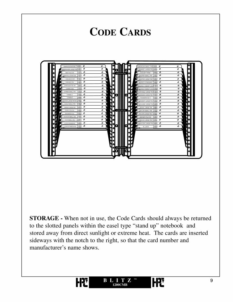
STORAGE - When not in use, the Code Cards should always be returnedto the slotted panels within the easel type “stand up” notebook andstored away from direct sunlight or extreme heat. The cards are insertedsideways with the notch to the right, so that the card number andmanufacturer’s name shows.
CODE CARDS

B L I T Z ™
1200CMB10
The code machine console fits your 1200CMB, bringing code cards,cutters and tools within easy reach.Additional storage panels and the code machine console may be orderedthrough your HPC Distributor.
Code Machine ConsoleNo. CWC-1
Additional PanelsPart No. CARD-BP
Code Card Storage CaseNo. CWC-1B

B L I T Z ™
1200CMB11
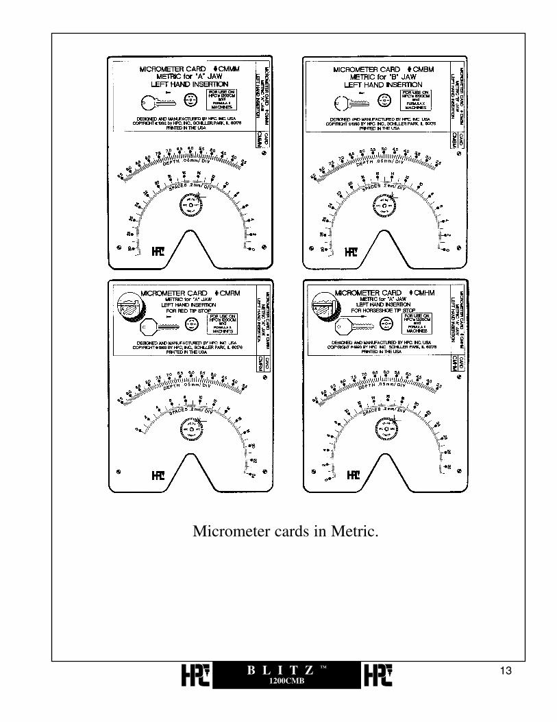
Universal micrometer cards allow you to cut keys to any lateral and depthdimension in thousandths of an inch (or hundredths of a millimeter).These eight cards provide the complete spectrum of flexibility of a “DialIndicator” type machine.
MICROMETER CARDS
CMMI Micrometer Card “A” Jaw (inch)CMBI Micrometer Card “B” Jaw (inch)CMRM Micrometer Card “A” Jaw (red tip-metric)CMRT Micrometer Card “A” Jaw (red tip-inch)CMHM Micrometer Card “A” Jaw (black tip-metric)CMHT Micrometer Card “A” Jaw (black tip-inch)CMMM Micrometer Card “A” Jaw (metric)CMBM Micrometer Card “B” Jaw (metric)

B L I T Z ™
1200CMB12
Micrometer cards in Standard.
B L I T Z ™
1200CMB13
Micrometer cards in Metric.

B L I T Z ™
1200CMB14
visit us online at:www.hpcworld.com

B L I T Z ™
1200CMB15
2.0CUTTERS

B L I T Z ™
1200CMB16
The Model-1200CMB is supplied with two high speed cutter wheels. The CW-1011 cutter is used for cabinet locks, padlocks and most automotive blanks.The CW-14MC cutter is used for most standard large cylinder keys.The Machine is delivered and set-up with the CW-14MC cutter and theCW-1011 cutter is placed in a slot in the styrofoam next to the machine.
CUTTERS SUPPLIED WITH
1200CM/CMB/MAX MACHINES
OPTIONAL CUTTERS FOR 1200CM/CMB/MAX
*Medeco® is a registered trademark of Medeco Security Locks, Inc.
No. CW-101190° angle, small cylinder cutter.
No. CW-14MC100° angle, standard large cylinder cutter.
No. CW-1013Only available cutter with exact angle of cut andfull “V” pin seat for Emhart High Security.
No. CW-1012Optional milling cutter has angle and pin seatfor cutting Medeco® High Security.

B L I T Z ™
1200CMB17
Optional cutters, such as CW-1012 (used with MJ-1 “C” jaw for thecutting of standard commercial Medeco® keys) are available. The correctcutter to be used is printed on each card. One of the important features ofthis machine, is its ability to maintain correct depths and spaces withvirtually no set-up time involved, even when changing cutters. Thisfeature is reliant upon using cutters whose outside diameters are matchedand equal.
OPTIONAL CUTTERS FOR 1200CM/CMB/MAX CONTINUED
No. CW-1014This specially designed cutter has .080 flat forone step cutting of Kwikset, Weslock, & Weiserusing original pins.
No. CW-20FM76° angle, double angle, flat mill tooth forSargent.
No. CW-32MCSpecially designed 90° angle, tool steel cutterfor ASSA keys with .032 flat.
No. CW-47MC87° angle, tool steel cutter.

B L I T Z ™
1200CMB18
SLOTTER CUTTERS FOR 1200CM/CMB/MAX
No. CW-90MC90° angle, large cylinder cutter for shallow &deep cuts in adjacent positions. For Best,Falcon, Eagle, Arrow, Kaba, and IC core.
No. CW-105105°, double angle cutter for ASSA.
No. CW-BC*.054 carbide slotter cutter for Yale.*(requires spacer SPR-5)
No. CW-CC*.058 carbide slotter cutter for S&G, Yale, LloydMatheson.*(requires spacer SPR-5)
OPTIONAL CUTTERS FOR
1200CMB/CMB/MAX CONTINUED

B L I T Z ™
1200CMB19
No. CW-DC*.064 carbide slotter cutter for S&G.*(requires spacer SPR-5)
No. CW-EC*.069 carbide slotter cutter for Diebold.*(requires spacer SPR-5)
No. CW-FC*.088 carbide slotter cutter for Mosler.*(requires spacer SPR-5)
No. CW-45SMS*.045 M2 tool steel combination standard/flatsteel cutter for safety deposit boxes. *(requires spacer SPR-5)
MORE SLOTTER CUTTERS FOR
1200CM/CMB/MAX
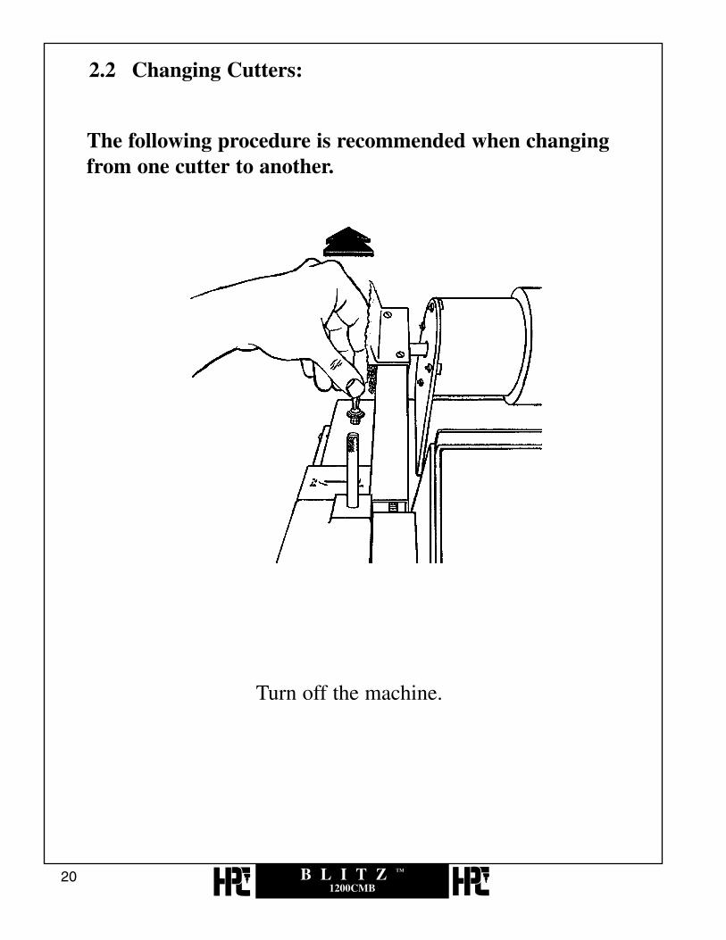
2.2 Changing Cutters:
B L I T Z ™
1200CMB20
The following procedure is recommended when changingfrom one cutter to another.
Turn off the machine.

B L I T Z ™
1200CMB21
Hold the cutter shaft fast with a 1/2” open end wrench. (No. WRENCH-1 supplied)

B L I T Z ™
1200CMB22
Loosen the cutter shaft nut, with a 3/4” open end wrench(No. WRENCH-3 supplied) by turning it clockwise (lefthand thread). Remove the cutter.

B L I T Z ™
1200CMB23
• Slide the replacement cutter wheel onto the shaft.IMPORTANT: Be sure cutter is installed for a clockwise rotation!
• Hold the shaft with the 1/2” wrench.
• Install the nut, turning it counter-clockwise onto the shaft with a 3/4” wrench. Do not overtighten the nut.

B L I T Z ™
1200CMB24
visit us online at:www.hpcworld.com
B L I T Z ™
1200CMB25
3.0GAUGING AND
HOLDING KEYS

3.1 Key Gauge Safety Switch
B L I T Z ™
1200CMB26
This machine is equipped with a Shoulder Gauge Safety Switch to protectthe shoulder gauge from being accidentally damaged by the cutter. Thistype of accident occurs if the shoulder gauge is left up at the key aftergauging rather than being lowered to its rest position before cutting the key.
Cutting A Key
To cut a key you must lower the gauge to its rest position before turning onthe cutter motor. Turning on the cutter motor is accomplished with theswitch at the rear of the machine. Turning on the machine’s cutter motorwith the shoulder gauge not in the rest position will result in the safetyswitch relay disengaging the cutter motor’s power. This will also happen ifthe gauge is moved from its rest position while the cutter motor is alreadyon.
Resetting the Machine
To reset the machine, lower the shoulder gauge to its rest position, then turnoff the machine with the regular switch located at the rear of the machine.The machine should now be turned back on to cut the key. Resetting themachine prevents the Shoulder Gauge Safety Switch from being used as apower switch to turn the machine on and off.

3.2 Key Gauges:
B L I T Z ™
1200CMB27
Shoulder Gauge
Black (Horseshoe) Tip GaugeNo. CM-1054R
Red (Plastic) Tip GaugeNo. CM-1054MA

B L I T Z ™
1200CMB28
visit us online at:www.hpcworld.com

3.3 Standard Gauging Using Jaw A:
B L I T Z ™
1200CMB29
No. CMB-FGShoulder Gauge
Place key blank in the jaw with the shoulder touching the left hand edge ofshoulder gauge. Flip the shoulder gauge down before turning on the motor.The space dimension can be significantly affected by any damage incurred tothe shoulder gauge.Damage to the shoulder gauge can occur when it comes in contact with thecutter, or when undue pressure is used when gauging against the key’s shoulder.
STANDARD CYLINDER KEYWITH SHOULDER GAUGING USING JAW A.
(Example: Schlage, Card No. C45)

B L I T Z ™
1200CMB30
Key vise tip gauge pulled to rear and into Position No. 1.
No. CM-1054MAKey Vise Tip Gauge

B L I T Z ™
1200CMB31
Make sure the key is lying flat against ledge beforetightening wing nut.
Wing nut and top jaw of vise removed to showa top view of the bottom jaw only, for key positioning.

B L I T Z ™
1200CMB32
visit us online at:www.hpcworld.com

3.4 Standard Gauging Using Jaw B:
B L I T Z ™
1200CMB33
Key shoulder touches left hand edge of shoulder gauge.Flip gauge down before turning on motor.
STANDARD CYLINDER KEYWITH SHOULDER GAUGING USING JAW B.
(Example: Master, Card No. C34)
No. CMB-FGShoulder Gauge

B L I T Z ™
1200CMB34
Key lies in front of lip. Key vise tip gauge pulled to rear.(Position No. 1)
No. CM-1054MATip Stop
B L I T Z ™
1200CMB35
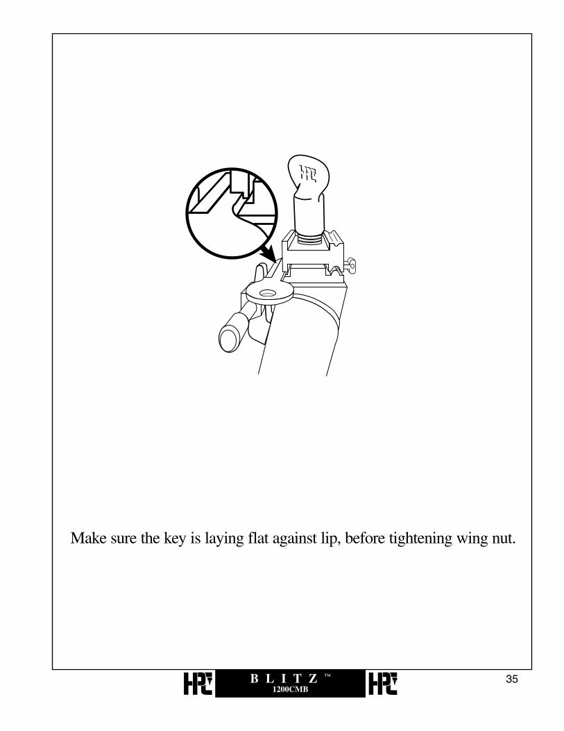
Make sure the key is laying flat against lip, before tightening wing nut.

B L I T Z ™
1200CMB36
HPC, Inc.Designer and
Manufacturer ofSecurity Products
Since 1956.

3.5 Red Full Short Tip Stop:
B L I T Z ™
1200CMB37
Key is gauged from tip.
RED FULL SHORT TIP STOPGAUGING USING JAW A.
(Example: Ford, Card No. C24)
No. CM-1054MATip Gauge

B L I T Z ™
1200CMB38
Key vise tip gauge, pushed inward to the third groove position.Tip gauge is pulled to rear while cutting.
No. CM-1054MAGauge in 3rd groove.

B L I T Z ™
1200CMB39
Key blank grooving ledge lies directly on face of key vise orkey vise base, for ignition and trunk keyway. No riser blocksare used.
Wing nut and top jaw of vise removed to showa top view of the bottom jaw only, for key positioningand stop bar settings.

B L I T Z ™
1200CMB40
visit us online at:www.hpcworld.com

3.6 Red Middle Short Tip Stop:
B L I T Z ™
1200CMB41
Key is gauged from bottom stop, not tip.
RED MIDDLE SHORT TIP STOPGAUGING USING JAW A.
(Example: KABA-PEAKS 6-Pin, Card No. CPKS1)
No. CM-1054MATip Gauge

B L I T Z ™
1200CMB42
Key vise tip gauge, pushed inward to the second groove position.Tip gauge is pulled to rear while cutting.
No. CM-1054MAKey Vise in 2nd Position.

B L I T Z ™
1200CMB43
Top jaw of vise removed to show a top view of the lowerjaw only, for key positioning and stop bar settings.
Gauge against tip stop. Be sure key lies flat against ledgebefore tightening wing nut.
*For BEST type blanks see section 3.5

B L I T Z ™
1200CMB44
Count on Quality:Demand HPC.

3.7 Black Horseshoe Tip Stop (Short End)
B L I T Z ™
1200CMB45
Key is gauged from bottom stop, not tip.(Note: Use black tip gauge, NOT red.)
BLACK HORSESHOE SHORT TIP STOPGAUGING USING JAW B.
(Example: Best Card No. C3)

B L I T Z ™
1200CMB46
Gauge pushed inward to first groove position.
B L I T Z ™
1200CMB47
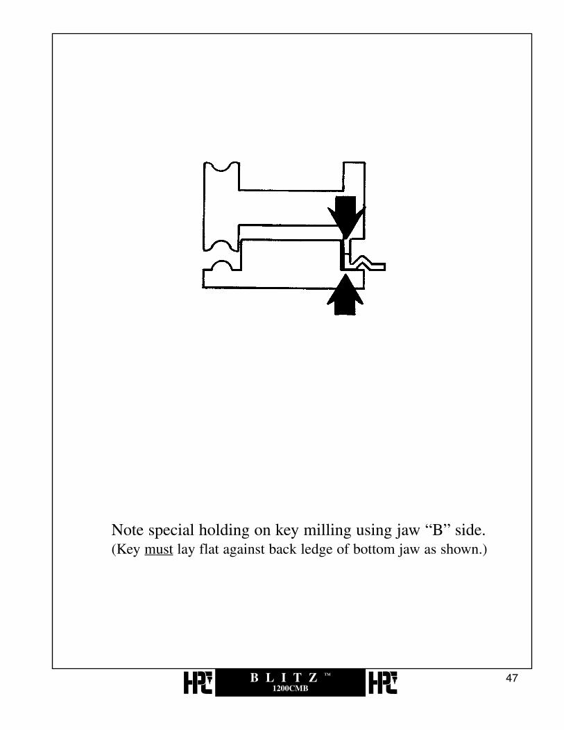
Note special holding on key milling using jaw “B” side.(Key must lay flat against back ledge of bottom jaw as shown.)

B L I T Z ™
1200CMB48
visit us online at:www.hpcworld.com

3.8 Medeco® Jaw C
B L I T Z ™
1200CMB49
Key shoulder touches left hand edge of shoulder gauge. Flipgauge down before turning on motor.
MEDECO® - STANDARD COMMERCIALUSING JAW C. (OPTIONAL EQUIPMENT)
(Example: Medeco® Card No. C36)
*Medeco® is a registered trademark of Medeco Security Locks, Inc.

B L I T Z ™
1200CMB50
Jaw and grooves “nest” into each other. Key vise tipgauge is pulled back to rear. Open jaw “C” only enough to slidekey into position. Be sure key groove and jaw milling matebefore tightening wing nut.
“Nested”

3.9 Black Horseshoe Tip Stop (Full End)
B L I T Z ™
1200CMB51
Key is gauged from tip as shown.(Note: Black tip gauge NOT Red.)
BLACK HORSESHOE FULL END TIP STOPGAUGING USING JAW A OR B.
(Example: GM Modular 94+, Card No. CF215)

B L I T Z ™
1200CMB52
Detent in second groove position.

B L I T Z ™
1200CMB53
Gauge against tip stop. Be sure key lies flat against ledgebefore tightening wing nut.

B L I T Z ™
1200CMB54
visit us online at:www.hpcworld.com

B L I T Z ™
1200CMB55
4.0DEPTH AND SPACE
CRANK CONTROLS

B L I T Z ™
1200CMB56
DEPTH CRANKTHE DEPTH OF A CUT is controlled by rotating the No. CM-1026X DepthCrank, located at the front of the machine. Clockwise rotation, as indicated above,moves the key inward towards the cutter. Counter-Clockwise rotation moves thekey outward and away from the cutter.
LATERAL CRANKTHE LATERAL MOVEMENT of the key is controlled by rotating the No. CM-1044X lateral crank located on the right hand side of the machine.Counter-clockwise rotation as indicated in the illustration, moves the key to theleft and causes the cutter to cut farther from the shoulder.
DEPTH CRANKClockwise rotation,cuts deeper.
LATERAL CRANKCounter-clockwiserotation, cuts fartherfrom shoulder.
Space Window
Depth Window

B L I T Z ™
1200CMB57
Rotating the depth crank clockwise, the pivot arm will move inwardtowards the cutter, rotating counter-clockwise will move it outward awayfrom the cutter.
The depth indicator needle sweeps across the face of the arc, from left toright as the knob is advanced. With this indicator needle centered over themark on the card, the key is cut to the corresponding depth.

B L I T Z ™
1200CMB58
Rotating the lateral crank clockwise moves the pivot arm to the right,and rotating counter-clockwise moves it to the left.

B L I T Z ™
1200CMB59
The key in the pivot arm is correctly positioned for the first spacewhen the space indicator needle is centered over the numeral 1 inthe space indicator arc.

B L I T Z ™
1200CMB60
visit us online at:www.hpcworld.com

B L I T Z ™
1200CMB61
5.0CUTTING THE KEY

B L I T Z ™
1200CMB62
Select the correct Code Card and insert it beneaththe lens as shown above.

B L I T Z ™
1200CMB63
Change the cutter and jaw (if necessary) to those indicated onthe Code Card.

B L I T Z ™
1200CMB64
For maximum clearance, and easy accessibility when insertingthe key blank, rotate both of the crank knobs counter-clockwise.

B L I T Z ™
1200CMB65
Gauge the key...

B L I T Z ™
1200CMB66
...and tighten the wing nut when the key is level. Then flip gaugedown before starting to cut.

B L I T Z ™
1200CMB67
Turn machine “ON.”

B L I T Z ™
1200CMB68
Rotate the lateral crank clockwise until the indicator lines up withthe No. 1 space mark in the space window as indicated above.

B L I T Z ™
1200CMB69
Slowly rotate the depth crank clockwise until the depthindicator is centered over the depth mark you wish to cutas shown in the upper depth window.
Do NOT pass the mark!

B L I T Z ™
1200CMB70
Now rotate the depth crank counter-clockwise (outward) until thespinning cutter is clear of the key blank.

B L I T Z ™
1200CMB71
Rotate the lateral crank to the second space indicator.

B L I T Z ™
1200CMB72
Slowly rotate the depth crank clockwise until the depth indicatoris centered once more over the depth you wish to cut in this space position.

B L I T Z ™
1200CMB73
Continue the correct space and depth movements until all cuts aremade from the head to the tip of the key.

B L I T Z ™
1200CMB74
Upon completion of the last cut rotate both of the crankscounter-clockwise for maximum clearance and easy accessibilityto the cut key. Then turn off machine and remove key.

B L I T Z ™
1200CMB75
Turn motor back on to deburr key.

B L I T Z ™
1200CMB76
The following is only for keys that require widening as indicatedon the code card.
When widening, start at the first small mark for each space and, whileholding the depth crank, turn the lateral crank counter-clockwise fromthe first small widening mark through the center mark and stopping at the second small widening mark.
Do NOT move back clockwise!

B L I T Z ™
1200CMB77
6.0ANGLE CUT KEYS

6.1 Use of Swivel Cutter Head
B L I T Z ™
1200CMB78
CUTTING KEYS FOR MEDECO®
STANDARD COMMERCIAL - CODE CARD NO. C36BIAXIAL - CODE CARD No.’s CSP3 and CSP4
ONE OF THE UNIQUE FEATURES OF THIS MACHINE - is the ability to makecuts on an angle. By pulling outward on the spring loaded angle index pin the cutterhead can be swiveled left or right. Be sure the index pin is re-locked into the cutterhead before operating machine.
•REQUIRED OPTIONAL EQUIPMENTAn optional cutter and Jaw “C” are required to cut keys for commercial level Medeco®.This cutter Part No. CW-1012 and No. MJ-1 “Jaw C” may be added at a later date. Bothparts are readily available from your HPC distributor.
Biaxial keys only require the CW-1012 cutter, not the MJ-1 “Jaw C”.
*Medeco® is a registered trademark of Medeco Security Locks, Inc.

6.1 Decoding and Cutting
B L I T Z ™
1200CMB79
The depths and angles must be decoded prior to cutting the key. Depths can bemeasured with a knife-edge caliper, a key micrometer or with one of the specialdecoders commercially available. The HPC Pocket Sized Decoder, No. HKD-75(pictured above), in addition to decoding depths and angles for Medeco® alsocontains an assortment of cards for other locks. Remember decoding devices are notdesigned to replace micrometers or calipers.
Install the No. CW1012and MJ-1 (Jaw “C”).
*Medeco® is a registered trademark of Medeco Security Locks, Inc.

B L I T Z ™
1200CMB80
Gauge the key from the shoulder, making sure the key groovingand special jaw milling are nested together.

B L I T Z ™
1200CMB81
Insert Code Card No. C36 for Medeco®.*Medeco® is a registered trademark of Medeco Security Locks, Inc.

B L I T Z ™
1200CMB82
Turn the lateral crank as required to move key into the correctspace positions for cuts with center angles. Cutter head is notswiveled for center cuts. Make all center angle cuts first.

B L I T Z ™
1200CMB83
C R C L L
C CUTTER: CW-1012
ME
DE
CO
STA
ND
AR
D
SERIES: CODES AVAILABLE
ONLY FROM MEDECO
LARTGE KEY A & B
SMALL KEYSD SF. SG, & LT
BLANKS: LARGE: 10-010 & 10-011
SMALL: 60-010/610
60-011/611
THICK HEAD STYLE KEYS ONLY
1 2 3 4 5 6
,LTKB-3
¥DSD#051 ¥ MACS=4 ¥ PROG. STEP-1
¥NOTE: ANGLE DIRECTION FIG. 1
¥NOTE: USE"C" JAW & MAKE SURE KEYWAY SLIDES INTO GROOVE FIG. 2
¥NOTE: ACCURACY OF DEPTH & ANGLE IS CRITICAL!!
.244
.030 TYP.
.170 TYP..266 6.75
6.2010.50
23.4027.70
19.10
14.806.005.25
4.503.753.00
.236
.206
.176
.146
.116
.244
.414
.584
.754
.9241.094
Cut first center cut.

B L I T Z ™
1200CMB84
Back off.

B L I T Z ™
1200CMB85
C R C L L
C CUTTER: CW-1012
ME
DE
CO
STA
ND
AR
D
SERIES: CODES AVAILABLE
ONLY FROM MEDECO
LARTGE KEY A & B
SMALL KEYSD SF. SG, & LT
BLANKS: LARGE: 10-010 & 10-011
SMALL: 60-010/610
60-011/611
THICK HEAD STYLE KEYS ONLY
1 2 3 4 5 6
,LTKB-3
¥DSD#051 ¥ MACS=4 ¥ PROG. STEP-1
¥NOTE: ANGLE DIRECTION FIG. 1
¥NOTE: USE"C" JAW & MAKE SURE KEYWAY SLIDES INTO GROOVE FIG. 2
¥NOTE: ACCURACY OF DEPTH & ANGLE IS CRITICAL!!
.244
.030 TYP.
.170 TYP..266 6.75
6.2010.50
23.4027.70
19.10
14.806.005.25
4.503.753.00
.236
.206
.176
.146
.116
.244
.414
.584
.754
.9241.094
Move to next center angle cut and plunge.

B L I T Z ™
1200CMB86
Back off.

B L I T Z ™
1200CMB87
Move away from cutter.

B L I T Z ™
1200CMB88
Turn off the machine.

B L I T Z ™
1200CMB89
Pull outward on angle index pin.

B L I T Z ™
1200CMB90
Swivel cutter head by the angle pivot pin, as indicated by the arrows.
B L I T Z ™
1200CMB91
C R C L L
C CUTTER: CW-1012
ME
DE
CO
STA
ND
AR
D
SERIES: CODES AVAILABLE
ONLY FROM MEDECO
LARTGE KEY A & B
SMALL KEYSD SF. SG, & LT
BLANKS: LARGE: 10-010 & 10-011
SMALL: 60-010/610
60-011/611
THICK HEAD STYLE KEYS ONLY
1 2 3 4 5 6
,LTKB-3
¥DSD#051 ¥ MACS=4 ¥ PROG. STEP-1
¥NOTE: ANGLE DIRECTION FIG. 1
¥NOTE: USE"C" JAW & MAKE SURE KEYWAY SLIDES INTO GROOVE FIG. 2
¥NOTE: ACCURACY OF DEPTH & ANGLE IS CRITICAL!!
.244
.030 TYP.
.170 TYP..266 6.75
6.2010.50
23.4027.70
19.10
14.806.005.25
4.503.753.00
.236
.206
.176
.146
.116
.244
.414
.584
.754
.9241.094
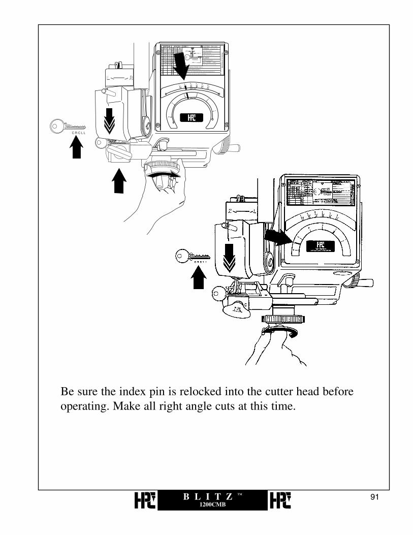
Be sure the index pin is relocked into the cutter head beforeoperating. Make all right angle cuts at this time.

B L I T Z ™
1200CMB92
Then turn off the machine.

B L I T Z ™
1200CMB93
Repeat the same procedure for left angle cuts.

B L I T Z ™
1200CMB94
Be sure to brush Medeco® keys exceptionally clean and free of allburrs. Hold the cut key so that the rotation of the deburring brushsweeps the burrs out and away from the cut.
*Medeco® is a registered trademark of Medeco Security Locks, Inc.

B L I T Z ™
1200CMB95
7.0RE-CALIBRATION
OF DEPTH

B L I T Z ™
1200CMB96
visit us online at:www.hpcworld.com

B L I T Z ™
1200CMB97
ATTENTION: PLEASE READ BEFORE PROCEEDING.
RE-CALIBRATION OF DEPTH
NO RE-ADJUSTMENT of depth is required when changing from one code cardto another. The depth indicator marks on each code card are positioned for correctalignment when using the factory cutter wheels. No special washers are requiredon either side of the cutter.
The need to re-adjust the depth is rare and should be done only after the morecommon causes for mis-cut keys are eliminated.
Remember, when originating a key by code you do not have access to an operablekey. Quite often code numbers are mis-read, locks are coded incorrectly whenthey are new and code books occasionally have typographical errors. Be aware ofthese unintentional errors that detract from the successful cutting of keys by code.After eliminating the above mentioned causes for mis-cut keys and checking forcorrect calibration with a caliper or micrometer - then proceed.
B L I T Z ™
1200CMB98
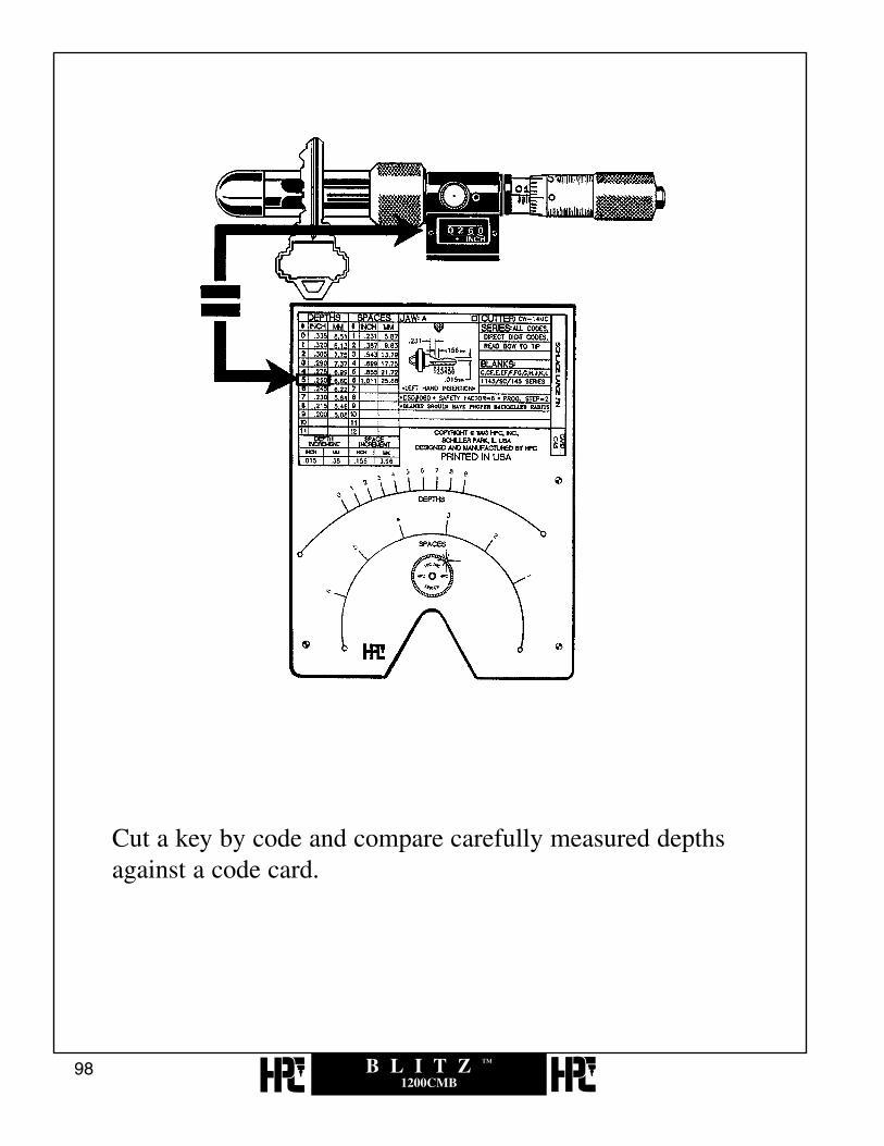
Cut a key by code and compare carefully measured depths against a code card.

B L I T Z ™
1200CMB99
The two flats on the end of the eccentric shaft allow a 3/8” open end wrench (such asNo. WRENCH-1) to rotate the eccentric shaft either towards you, making the depthsdeeper, or away, making the depths shallower. There should be no need to loosenthe two set screws. The maximum range of the eccentric shaft is 90° when pullingtowards you (a maximum of -.015” in depth change) and 90° when pushing away (amaximum of +.015” in depth change). Therefore only a small turn is used to changedepths.
No. WRENCH-1
Very rapid minor depth adjustments are made by comparing the depth of a cut against the code card and then rotating the eccentric shaft slightly as required.

B L I T Z ™
1200CMB100
HPC, Inc.Designer and
Manufacturer ofSecurity Products
Since 1956.
B L I T Z ™
1200CMB101
8.0RE-CALIBRATION
OF SPACE

B L I T Z ™
1200CMB102
visit us online at:www.hpcworld.com

B L I T Z ™
1200CMB103
ATTENTION: PLEASE READ BEFORE PROCEEDING.
RE-CALIBRATION OF SPACE
NO RE-ADJUSTMENT of space is required when changing from one codecard to another. The space indicator marks on each code card are positioned forcorrect lateral alignment when using the factory cutter wheels. No specialspacing washers are required on either side of the cutter.
The need to re-adjust the space is rare and should be done only after the morecommon causes for mis-cut keys are eliminated.
Remember, when originating a key by code you do not have access to anoperable key. Quite often code numbers are mis-read, locks are codedincorrectly when they are new and code books occasionally have typographicalerrors. Be aware of these unintentional errors that detract from the successfulcutting of keys by code. After eliminating the above mentioned causes for mis-cut keys and checking for correct depth calibration - then proceed.
If re-adjustment of space is needed, follow the instructions for tip-gauged spaceadjustments first. Then proceed with shoulder-gauged space adjustments.Because the tip gauges are built into the bottom jaw and the shoulder gauge ismounted on its own pivot, re-adjusting the shoulder gauge may not properly re-calibrate your 1200CMB.
8.1 Cutting Too Close or Too Far From the Tip
B L I T Z ™
1200CMB104
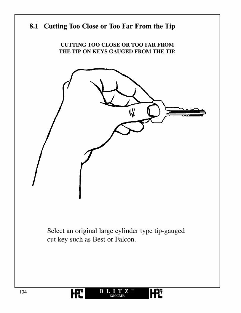
CUTTING TOO CLOSE OR TOO FAR FROM THE TIP ON KEYS GAUGED FROM THE TIP.
Select an original large cylinder type tip-gauged cut key such as Best or Falcon.

B L I T Z ™
1200CMB105
Put on the correct cutter and insert the correct card. Then, gauge and clamp the key.

B L I T Z ™
1200CMB106
Place a white piece of paper beneath the cutter for improvedvision of alignment.
NOTE: Unplug machine for these and the following operations.

B L I T Z ™
1200CMB107
Rotate lateral crank to position the key with the most easily seencut carefully centered beneath the cutter as shown. Rotate thedepth crank until the cutter is fairly deep within the cut,(Deepest cuts are usually the easiest to see.)

B L I T Z ™
1200CMB108
If space indicator needle is centered over the correspondingspace mark the space adjustment is correct. Go no further.

B L I T Z ™
1200CMB109
If the space indicator needle is offset to the right, the machineis cutting too close to the tip.If the space indicator is offset to left, the machine is cutting tofar from tip.(Note:Re-calibration of tip does necessitate re-calibration ofshoulder space. See next section.)

B L I T Z ™
1200CMB110
Rotate the lateral crank until the indicator needle is centered overthe corresponding space mark as shown. Rotate the Depth crankuntil the cutter is fairly deep within the cut.

B L I T Z ™
1200CMB111
Loosen the four set screws that hold the pivot arm onto the pivotarm shaft. DO NOT REMOVE PIVOT ARM.

B L I T Z ™
1200CMB112
Re-position the space indicator needle if it has moved whileloosening the set screws.

B L I T Z ™
1200CMB113
With a small rawhide or plastic mallet, “lightly” tap the lower leftside of the pivot arm until the pin seat of the cut is directlyopposite the flat of the cutter, as shown previously. (Be sure allFOUR set screws are loose.)

B L I T Z ™
1200CMB114
With the cutter aligned opposite the cut and the space indicatorneedle centered over the corresponding space mark, tilt the machineup, if necessary, (without disturbing the setting) and re-tighten theset screws.

8.2 Cutting Too Close or Too Far From the Shoulder
B L I T Z ™
1200CMB115
CUTTING TOO CLOSE OR TOO FAR FROM THESHOULDER ON KEYS GAUGED FROM THE SHOULDER.
Select an original large cylinder type shoulder-gauged cut key,such as Schlage.*Always check spacing on a tip stop key first, before adjustingfor shoulder-gauged keys.

B L I T Z ™
1200CMB116
Insert the correct Code Card. Put on the correct cutter.

B L I T Z ™
1200CMB117
Gauge and clamp the key.

B L I T Z ™
1200CMB118
Place a white piece of paper of paper beneath the cutter forimproved vision alignment.

B L I T Z ™
1200CMB119
Rotate lateral crank to position the key with the most easily seencut carefully centered beneath the cutter as shown. Rotate thedepth crank until the cutter is fairly deep within the cut. If spaceindicator needle is centered over the corresponding space mark,the space adjustment is correct. Go no further.

B L I T Z ™
1200CMB120
If the space indicator needle is offset to the right, the machine iscutting too far from the shoulder.If the space indicator needle is offset to left, the machine iscutting too close to the shoulder.(Note: Recalibration of shoulder spacing does not necessitate recalibration of tip space.)

B L I T Z ™
1200CMB121
NOTE: Unplug the machine for these andthe following operations.
Rotate the lateral crank towards you until the space indicator needle is centered over the corresponding space mark as shown.

B L I T Z ™
1200CMB122
Loosen the key on the vise. Slide the key until the pin seat of thecut is directly opposite the flat of the cutter as shown. Tighten thekey on the vise.

B L I T Z ™
1200CMB123
Loosen the set screw that holds the shoulder gauge turn bar ontothe (CM-1024X) pivot arm.
B L I T Z ™
1200CMB124
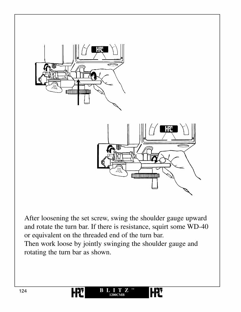
After loosening the set screw, swing the shoulder gauge upwardand rotate the turn bar. If there is resistance, squirt some WD-40or equivalent on the threaded end of the turn bar.Then work loose by jointly swinging the shoulder gauge androtating the turn bar as shown.

B L I T Z ™
1200CMB125
Now that the turn bar is loose, rotate the turn bar clockwise orcounter-clockwise to move the shoulder gauge toward theshoulder of the key. The left side of the gauge should end upjust barely touching the shoulder of the key as shown (as innormal gauging) do not use pliers or any tool that will scratchor mar the surface of the turn bar.

B L I T Z ™
1200CMB126
Tighten the set screw that holds the turn bar onto the pivot arm.

B L I T Z ™
1200CMB127
9.0PREVENTIVE
MAINTENANCE,LUBRICATION, REPAIRS
AND GUARANTEE

B L I T Z ™
1200CMB128
LUBRICATION, PREVENTIVE MAINTENANCE,REPAIRS and GUARANTEE
1 -MOTOR - The motor is equipped with sealed bearings that require no lubrication.2 -CUTTER HEAD - The cutter head is equipped with precision ball bearings for years of trouble freeservice and requires no lubrication. The cutter head swivel surface and plunger angle holes should be givena light coat of LPS#3 or equivalent, once every 4 to 6 months.3 -DEPTH FEED CRANK BEARING - The black Delrin bearing (No. CM-1045) should be cleaned anda light coat of heavy grease applied when required, in order to maintain it’s smooth feel.4 -BEARINGS AND SLIDING SURFACES - These are to be given a light coat of a light grease at least every six months.5 -EXPOSED STEEL SURFACES - All remaining exposed steel shafts, cutter, etc., should be sprayed with WD-40 or equivalent light oil at least every 6 months. Wipe off any excess.6 -CLEANING - Remove all brass chips, dirt and grit from the surface of your machine daily, with a soft bristle brush. Take particular care in keeping the key vise jaw area clean and free of all residue build-up.7 -CODE CARDS - The Code Cards are made of credit card stock and die cut to extremely closetolerances. Dirt is easily washed off with a mild non-abrasive liquid detergent, such as dishwashingsoap and lukewarm water. Dab lightly with a soft coat until dry. Never use an abrasive or solvent-basedcleaner to wash these Code Cards!8 -CALIBRATING DEPTH FOR RE-SHARPENED CUTTERS - The diameter of a resharpened cutter is,smaller and therefore will make cuts shallower-if no depth adjustment is made. This is easily accomplishedby rotating the eccentric shaft with a 3/8” open end wrench.*See depth adjustment section (Section 6.0) for full explanation of the eccentric shaft adjusting process.As cutters become worn, the alternative to purchasing a new set, would be to resharpen them. (HPC doesnot resharpen cutters.)In order to maintain matched cutter diameters, all cutters for this machine must be sharpened at the sametime, and all diameters must be sharpened proportionately.9 -DRIVE BELT - The drive belt (No. CM-1083MA) was selected especially for this machine and should give years of good service. If it becomes worn or broken and requires replacement, be sure toinstall the new belt with the teeth outward. Note: The drive belt is somewhat more noisy when it is madeto “cross-over” as the cutter head is swiveled to either the left or right angle when cutting Medeco® keys.10 -GUARANTEE - The 1200CMB Code Machine is fully guaranteed for one year from the date ofpurchase, against factory defects in material and workmanship. Mail the Warranty Card to us immediately,to validate your guarantee. Should your machine require factory repairs, it should be packed securely,along with a letter stating clearly what you feel the problem is and returned to the factory.
During the one year warranty period, you will be billed for handling and shipping only. Neither HPC, Inc.nor our distributors have “loaner machines” available.
*Medeco® is a registered trademark of Medeco Security Locks, Inc.

B L I T Z ™
1200CMB129
HPC SERVICE CENTER
If the need should arise, please note the following in order to assure you, our customer, of prompt service on your key machine repair:
1. The HPC Service Center answers questions involving key machines and related parts Monday through Friday from 8:00am to4:30pm Central time.
2. REPAIRS - The preventive maintenance and recalibration of space and depth are the only repairs or adjustments suggested.Every effort has been made to thoroughly field test every machine for both permanent shop and/or service truck installations.Internal operating mechanisms, while extremely simple in function and design, are factory repairable only. Additional repaircharges may be incurred by attempting to fix these type of repairs yourself.
3. Parts for repairing any HPC key machine can be purchased directly through the Service Center by calling our toll-free phonenumber: 1-800-323-3295. When ordering any parts over the phone, please have a list of the part numbers and descriptions readyto expedite the ordering process. If the parts are needed in a hurry, they can be sent out UPS Next Day Air or 2nd Day Air.There is an extra cost incurred when parts are shipped this way.
4. If you need to send an HPC key machine in for repair, pack the machine securely in a box strong enough to prevent damageduring shipping. Also be sure that your machine is equipped with an HPC cutter when it is sent in for repairs. Include a letterexplaining exactly what type of problem you are having and any other work you may want done on the machine. Make sureyour address and phone number are on the letter as well as the name of someone we can contact if the need arises whilerepairing your machine. Our shipping address is:
HPC, Inc. Attn. Service Center3999 N. 25th AvenueSchiller Park, IL 60176
5. The usual method of payment for key machine parts is C.O.D. Other methods of payment include Visa, Mastercard or pre-payingyour order with a check. If you wish to have your HPC distributor billed for the cost of repairs, they will have to call in withapproval of the billing and a purchase order for the work being done, before the machine is repaired. Unless otherwise specified,key machines that are not under warranty will be shipped C.O.D. via UPS after the repairs have been made.
6. If you wish for the service department to call you with an estimate for repair of your machine, please specify this request inwriting.
7. If while inspecting your machine our service department discovers additional problems not listed in your note, a servicetechnician will call you with this information and the estimated charges to repair.
8. If no request is made for HPC to call with a repair estimate, but the cost is expected to exceed $250.00 or 25% of the cost of anew machine, you will be contacted with this information.
9. You will be called if the C.O.D. amount will exceed $250.00.
10. If after informing you of the repair estimate it becomes apparent that the cost will be higher, you will receive a call informingyou of the additional charges before any additional work is done.
11. We are sorry, but neither HPC, Inc. nor our distributors have “loaner machines” available.
Additional Authorized HPC Service Centers:
EASTERN CANADA:Eric DucharmeA.A. & E. Machine Repair37 Bluebell CircleWhitby, Ontario L1P1L2
WEST COAST AREA:Mario Arauzc/o LaGard, Inc.3330 Kashiwa StreetTorrance, CA 90505

B L I T Z ™
1200CMB130
visit us online at:www.hpcworld.com

B L I T Z ™
1200CMB131
10.0EXPLODED VIEWS &
PART LISTINGS

B L I T Z ™
1200CMB132
1200CMB PARTS LISTING
# Description Stock #
1. Pivot Arm Complete CM1024X2. Cutter Nut CM-1039MA3. Cutter Sold Separately4. Cutter Head Assembly CM1053X5. Spring CM-10796. Washer CM-501007. Pivot Pin CM-10438. Hex Nut CM-501579. Belt CM-1083MA
10. Cap Screw CM-5015811. Angle Index Pin CM-104212. Hex Nut CM-5014813. Toggle Switch CM-1099MA14. Crank Bearing CM-104515. Set Screw 9100-1116. Motor Pulley CM-1060B17. Washer CM-5014918. Motor (110 V) CM-1080MA19. Cap Screw CM-5016720. Washer CM-50167-121. Motor Mounting Bracket CM-1040MA22. Set Screw CM-50165
# Description Stock #
23. Cotter Pin CM-62CP24. Retaining Ring CM-5011225. Screw CM-5013426. Lateral Crank Complete CM-1044X27. Lateral Rack Bracket CM-1030 28. Pivot Arm Shaft CM-103429. Rubber Foot CM-50133MA30. Dogging Screw CM-101631. Teflon Washer CM-108632. Washer CM-5010033. Spring CM-109834. Retaining Ring CM-5012635. Depth Crank Complete CM-1026X36. Dial Plate Complete CM-105037. Lateral Feed Shaft CM-1047B 38. Lens CM-101239. Brush TYX-340. Brush Nut 9150-2941. Belt Guard CM-1014B42. Brush Guard CM-1096B43. Screw CM-5015444. AC-Cord CM-1294MAO45. Motor Support CM-5018646. Motor Support Screws (2) CM-50188

B L I T Z ™
1200CMB133
18
25
45
46
100303
1200CMB

B L I T Z ™
1200CMB134
1200CMBDC PARTS LISTING
# Description Stock #
1. Pivot Arm Complete CM1024X2. Cutter Nut CM-1039MA3. Cutter Sold Separately4. Cutter Head Assy. Complete CM-1053X5. Spring CM-10796. Washer CM-501007. Pivot Pin CM-10438. Hex Nut CM-501579. Belt CM-1083MA
10. Cap Screw CM-5015811. Angle Index Pin CM-104212. Hex Nut CM-5014813. Toggle Switch CM-1099MA14. Serial Number Tag N/A15. Set Screw 9100-1116. Motor Pulley CM-1060B17. Washer CM-5014918. Motor (12 V DC) DC-MOTOR19. Cap Screw CM-5016720. Washer CM-50167-121. Motor Mounting Bracket CM-1040MA22. Set Screw CM-5016523. Cutter Pin CM-62CP
# Description Stock #
24. Retaining Ring CM-5011225. DC-Cord DC-CABLE26. Lateral Crank Complete CM-1044X27. Lateral Rack Bracket CM-103028. Pivot Arm Shaft CM-103429. Rubber Foot CM-50133MA30. Dogging Screw CM-101631. Teflon Washer CM-108632. Washer CM-5010033. Spring CM-109834. Retaining Ring CM-5012635. Depth Crank Complete CM-1026X36. Depth Crank Shaft CM-1031B 37. Dial Plate Complete CM-105038. Lateral Feed Shaft CM-1047B 39. Lens CM-101240. Screw CM-5015441. Brush TYX-342. Brush Nut 9150-2943. Belt Guard CM-1014B44. Brush Guard CM-1096B45. Screw CM-5013446. DC Motor Support CM-5018747. DC Motor Support Screws (2) CM-50188

B L I T Z ™
1200CMB135
1200CMBDC
14
25
18
100303
47
46

B L I T Z ™
1200CMB136
1200CMBACDC PARTS LISTING
# Description Stock #
1. Pivot Arm Complete CM1024X2. Cutter Nut CM-1039MA3. Cutter Sold Separately4. Cutter Head
Assembly Complete CM1053X5. Spring CM-10796. Washer CM-501007. Pivot Pin CM-10438. Hex Nut CM-501579. Belt CM-1083MA
10. Cap Screw CM-5015811. Angle Index Pin CM-104212. Hex Nut CM-5014813. Toggle Switch ACDC-SW14. Crank Bearing CM-104515. Set Screw 9100-1116. Motor Pulley CM-1060B 17. Washer CM-5014918. Motor (12 V DC) DC-MOTOR19. Cap Screw CM-5016720. Washer CM-50167-121. Motor Mounting Bracket CM-1040MA22. Set Screw CM-5016523. Cotter Pin CM-62CP24. Retaining Ring CM-5011225. Cap Screw CM-5013426. Lateral Crank Complete CM-1044X27. Lateral Rack Bracket CM-103028. Pivot Arm Shaft CM-1034
# Description Stock #
29. Rubber Foot CM-5013330. Dogging Screw CM-101631. Teflon Washer CM-108632. Washer CM-5010033. Spring CM-109834. Retaining Ring CM-5012635. Depth Crank Complete CM-1026X36. Depth Crank Shaft CM-1031B 37. Transformer for ACDC ACDC-TRANS39. Set Screw CM-5011238. Dial Plate Complete CM-105039. Lateral Feed Shaft CM-1047B 40. Screw CM-5015441. Lens CM-101242. Brush TYX-343. Screw CM-5013444. Belt Guard CM-1014B45. Brush Guard CM-1096B46. Screw CM-5017747. Cap Screw 9100-2848. Washer CM-5013049. Base CM-1255MAO50. Rectifier ACDC-RECT51. Cap Screw CM-5016752. AC Cord CM-1294MAO53. DC-Cord DC-CABLE54. DC Motor Support CM-5018755. DC Motor Support Screws (2) CM-50188

B L I T Z ™
1200CMB137
1200CMBACDC
14
2537
52
53
54
55
100303
B L I T Z ™
1200CMB138
6
5
4
012302
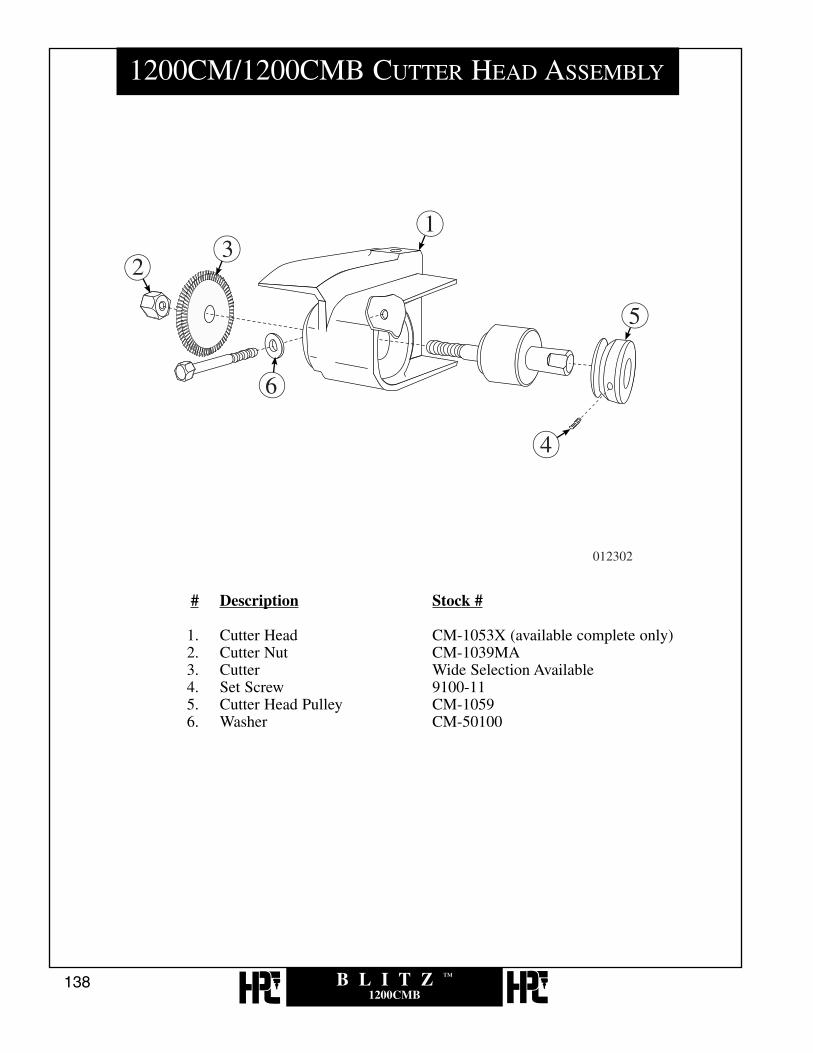
1200CM/1200CMB CUTTER HEAD ASSEMBLY
# Description Stock #
1. Cutter Head CM-1053X (available complete only)2. Cutter Nut CM-1039MA3. Cutter Wide Selection Available4. Set Screw 9100-115. Cutter Head Pulley CM-10596. Washer CM-50100

B L I T Z ™
1200CMB139
1
2
34
56
7
8910
11
12
1314
15
16
17
1819 20 21
13
051302
23
24
25
26
27
22
1200CM/1200CMB PIVOT ARM ASSEMBLY
# Description Stock #
1. Wing Nut SNK-32. Ball Bearing Washer BBW-23. Top Jaw CM-1056MA4. Spring CM-1293MA5. Stud CM-1019MA6. Ball Bearing CM-501087. Set Screw CM-501108. Bottom Jaw (factory installation recommended) CM-1055MA9. Tip Stop CM-1054MA
10. Spring CM-1090MA11. Set Screw CM-5013912. Eccentric Shaft CM-104113. Set Screw CM-5010914. Set Screw CM-5011215. & 16 Turn Bar & Shoulder Gauge CMB-FG17. Retaining Ring CM-5010518. 2-56 Screw MAX-9219. Shoulder Gauge Wire Assembly MAX-9020. Shoulder Gauge Micro Switch Bracket MAX-9121. 6-32 Set Screw MAX-8922. Specialty Tip Stop - Safe Deposit Keys RT-SD23. Horseshoe Tip Stop CM-1054R24. Specialty Tip Stop - Safe Deposit Keys HT-SD25. Specialty Tip Stop - L & F Safe Deposit Box Keys HT-12526. Specialty Tip Stop - L & F Safe Deposit Box Keys HT-62527. Easy Flip EFLIP-1200

B L I T Z ™
1200CMB140
012302
1200CMB RACK BRACKET ASSEMBLY
# Description Stock #
1. Rack Bracket CM-1030B2. Lateral Rack CM-10213. Screw CM-501124. Feed Thread CM-1037B5. Washer CM-101506. Screw CM-501167. Lateral Feed Shaft CM-1047B8. Brake Pellet CM-501809. Spring CM-50181
10. Set Screw CM-5018211. Ring CM-50183


Recommended