JFSBEIJING JOINT FLOW SYSTEM CO.
FIXED CONE VALVE
FIXED CONE VALVE
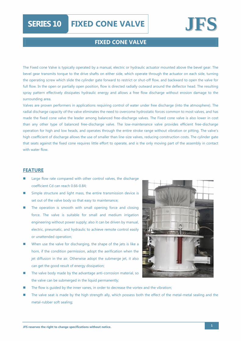
FIXED CONE VALVE SERIES 10 JJFFSS The Fixed cone Valve is typically operated by a manual, electric or hydraulic actuator mounted above the bevel gear. The bevel gear transmits torque to the drive shafts on either side, which operate through the actuator on each side, turning the operating screw which slide the cylinder gate forward to restrict or shut-off flow, and backward to open the valve for full flow. In the open or partially open position, flow is directed radially outward around the deflector head. The resulting spray pattern effectively dissipates hydraulic energy and allows a free flow discharge without erosion damage to the surrounding area. Valves are proven performers in applications requiring control of water under free discharge (into the atmosphere). The radial discharge capacity of the valve eliminates the need to overcome hydrostatic forces common to most valves, and has made the fixed cone valve the leader among balanced free-discharge valves. The Fixed cone valve is also lower in cost than any other type of balanced free-discharge valve. The low-maintenance valve provides efficient free-discharge operation for high and low heads, and operates through the entire stroke range without vibration or pitting. The valve's high coefficient of discharge allows the use of smaller than line-size valves, reducing construction costs. The cylinder gate that seats against the fixed cone requires little effort to operate, and is the only moving part of the assembly in contact with water flow.
FEATURE Large flow rate compared with other control valves, the discharge
coefficient Cd can reach 0.66-0.84;
Simple structure and light mass, the entire transmission device is
set out of the valve body so that easy to maintenance;
The operation is smooth with small opening force and closing
force. The valve is suitable for small and medium irrigation
engineering without power supply; also it can be driven by manual,
electric, pneumatic, and hydraulic to achieve remote control easily
or unattended operation;
When use the valve for discharging, the shape of the jets is like a
horn, if the condition permission, adopt the aerification when the
jet diffusion in the air. Otherwise adopt the submerge jet, it also
can get the good result of energy dissipation;
The valve body made by the advantage anti-corrosion material, so
the valve can be submerged in the liquid permanently;
The flow is guided by the inner vanes, in order to decrease the vortex and the vibration;
The valve seat is made by the high strength ally, which possess both the effect of the metal-metal sealing and the
metal-rubber soft sealing;
JFS reserves the right to change specifications without notice. 1
FIXED CONE VALVE
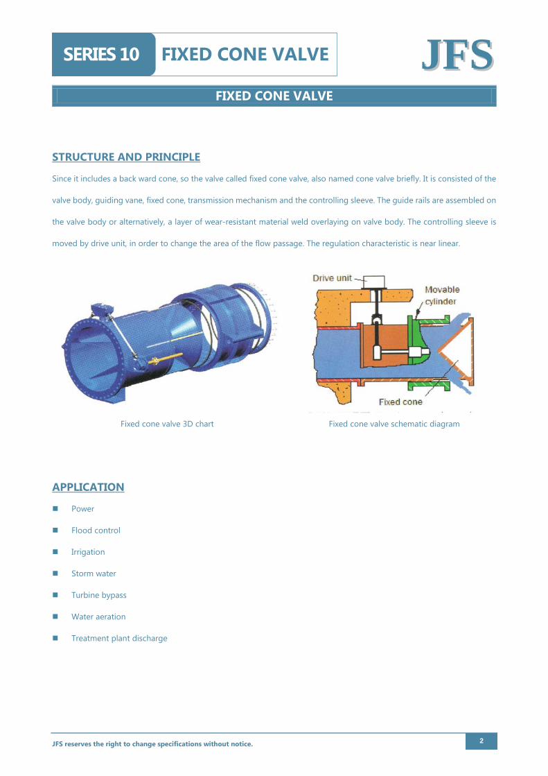
FIXED CONE VALVE SERIES 10 JJFFSS STRUCTURE AND PRINCIPLE
Since it includes a back ward cone, so the valve called fixed cone valve, also named cone valve briefly. It is consisted of the
valve body, guiding vane, fixed cone, transmission mechanism and the controlling sleeve. The guide rails are assembled on
the valve body or alternatively, a layer of wear-resistant material weld overlaying on valve body. The controlling sleeve is
moved by drive unit, in order to change the area of the flow passage. The regulation characteristic is near linear.
Fixed cone valve 3D chart Fixed cone valve schematic diagram
APPLICATION
Power
Flood control
Irrigation
Storm water
Turbine bypass
Water aeration
Treatment plant discharge
JFS reserves the right to change specifications without notice. 2
FIXED CONE VALVE
FIXED CONE VALVE SERIES 10 JJFFSS
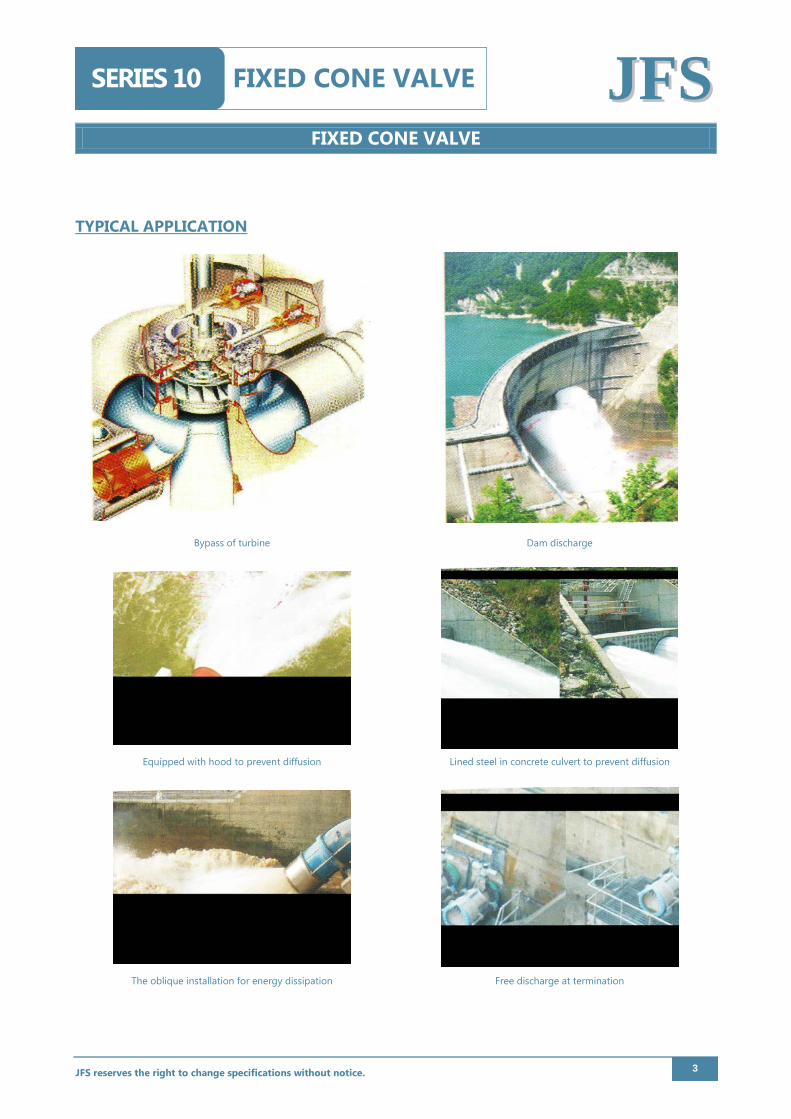
TYPICAL APPLICATION
Bypass of turbine Dam discharge
Equipped with hood to prevent diffusion Lined steel in concrete culvert to prevent diffusion
The oblique installation for energy dissipation Free discharge at termination
JFS reserves the right to change specifications without notice. 3
FIXED CONE VALVE
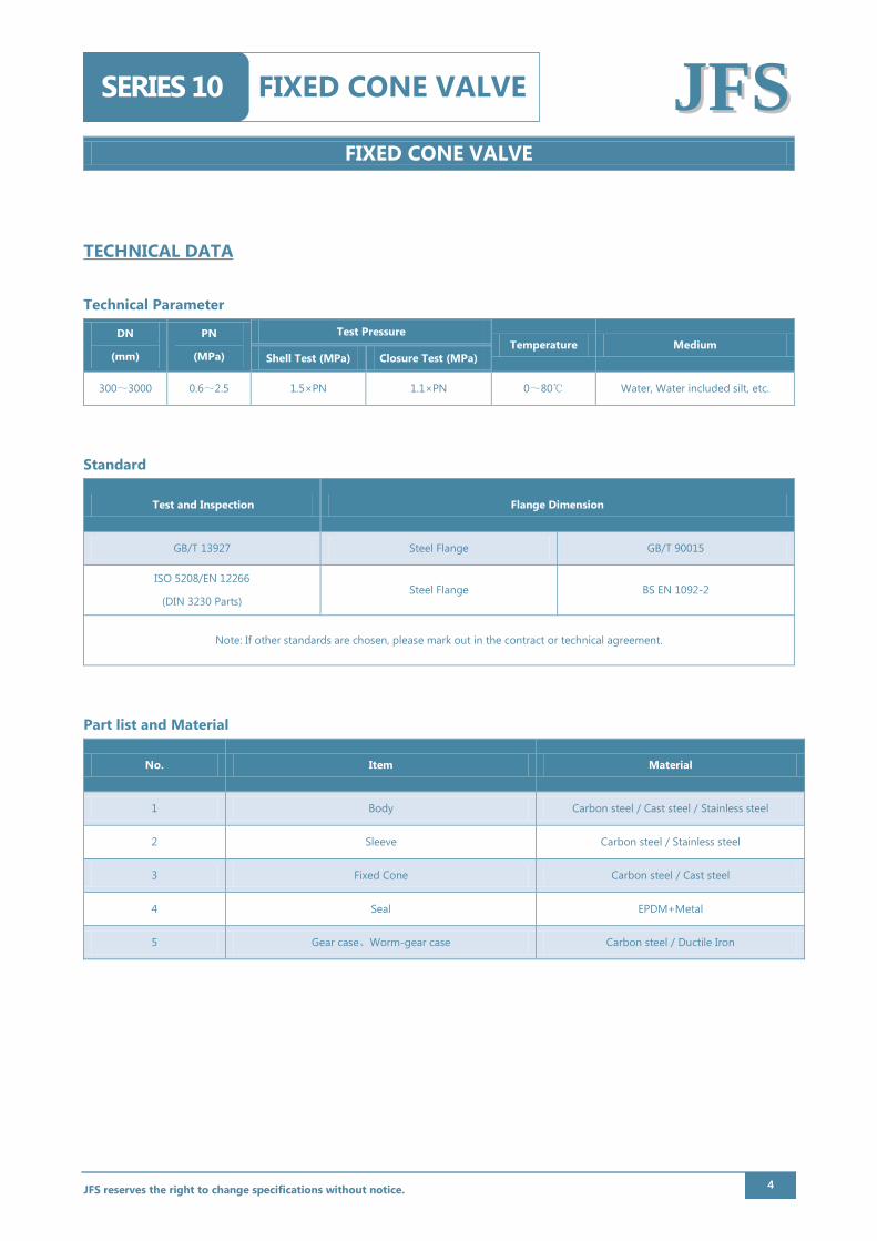
FIXED CONE VALVE SERIES 10 JJFFSS TECHNICAL DATA Technical Parameter
DN
(mm)
PN
(MPa)
Test Pressure Temperature Medium
Shell Test (MPa) Closure Test (MPa)
300~3000 0.6~2.5 1.5×PN 1.1×PN 0~80℃ Water, Water included silt, etc.
Standard
Test and Inspection Flange Dimension
GB/T 13927 Steel Flange GB/T 90015
ISO 5208/EN 12266
(DIN 3230 Parts) Steel Flange BS EN 1092-2
Note: If other standards are chosen, please mark out in the contract or technical agreement.
Part list and Material
No. Item Material
1 Body Carbon steel / Cast steel / Stainless steel
2 Sleeve Carbon steel / Stainless steel
3 Fixed Cone Carbon steel / Cast steel
4 Seal EPDM+Metal
5 Gear case、Worm-gear case Carbon steel / Ductile Iron
JFS reserves the right to change specifications without notice. 4
FIXED CONE VALVE
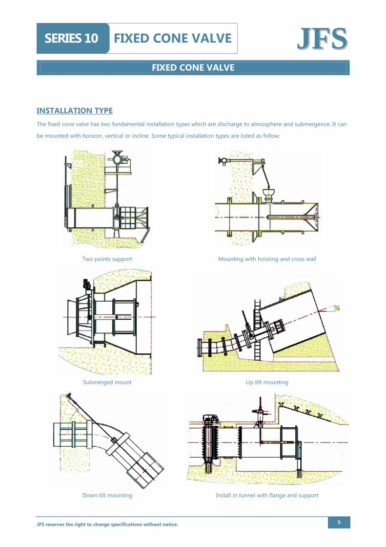
FIXED CONE VALVE SERIES 10 JJFFSS INSTALLATION TYPE The fixed cone valve has two fundamental installation types which are discharge to atmosphere and submergence. It can
be mounted with horizon, vertical or incline. Some typical installation types are listed as follow:
Two points support Mounting with hoisting and cross wall
Submerged mount Up tilt mounting
Down tilt mounting Install in tunnel with flange and support
JFS reserves the right to change specifications without notice. 5
FIXED CONE VALVE
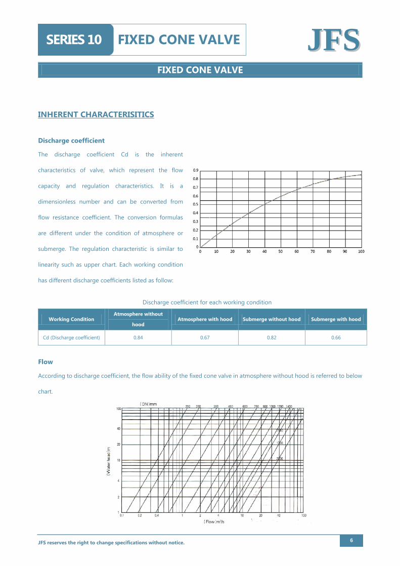
FIXED CONE VALVE SERIES 10 JJFFSS INHERENT CHARACTERISITICS
Discharge coefficient
The discharge coefficient Cd is the inherent
characteristics of valve, which represent the flow
capacity and regulation characteristics. It is a
dimensionless number and can be converted from
flow resistance coefficient. The conversion formulas
are different under the condition of atmosphere or
submerge. The regulation characteristic is similar to
linearity such as upper chart. Each working condition
has different discharge coefficients listed as follow:
Discharge coefficient for each working condition
Working Condition Atmosphere without
hood Atmosphere with hood Submerge without hood Submerge with hood
Cd (Discharge coefficient) 0.84 0.67 0.82 0.66
Flow
According to discharge coefficient, the flow ability of the fixed cone valve in atmosphere without hood is referred to below
chart.
JFS reserves the right to change specifications without notice. 6
FIXED CONE VALVE
FIXED CONE VALVE SERIES 10 JJFFSS SIZING INFORMATION
Application medium;
Working temperature;
Maximum working pressure;
Minimum pressure difference @ max flow
Selection by flow
Based on below formula, only need know the maximum required flow rate and the pressure, the DN of the valve can be
calculated.
d= 2gQ C A H
Q- Flow rate, m3/s;
g- Gravity acceleration, here is 9.81m2/s;
A- The area of the valve intake, A=πD2/4, D from the DN of the valve, the unit is m.
H- The pressure difference. The valve inlet total pressure should be minus the outlet static pressure which takes the valve
centerline elevation as the baseline.
Cavitation Check
The allowable cavitation coefficientσof fixed cone valve is 0.4. If exceed the value, the air supply or multiple level energy
dissipation should be adopted. The cavitation would be occurring with higher possibility if valve with hood.
2g=
2g
VP P
Vρσ
−
P- Absolute pressure of outlet, Pa;
PV- Saturated vapor pressure at working temperature, 2338.8 Pa at 20 ℃;
ρ- Density, water is 1000Kg/m3;
g- Gravity acceleration, here is 9.81m2/s
JFS reserves the right to change specifications without notice. 7
FIXED CONE VALVE
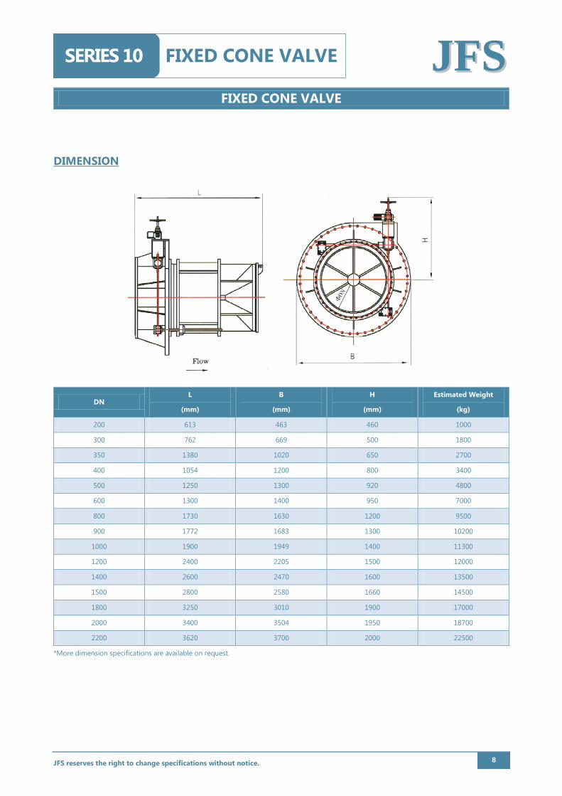
FIXED CONE VALVE SERIES 10 JJFFSS DIMENSION
DN L
(mm)
B
(mm)
H
(mm)
Estimated Weight
(kg)
200 613 463 460 1000
300 762 669 500 1800
350 1380 1020 650 2700
400 1054 1200 800 3400
500 1250 1300 920 4800
600 1300 1400 950 7000
800 1730 1630 1200 9500
900 1772 1683 1300 10200
1000 1900 1949 1400 11300
1200 2400 2205 1500 12000
1400 2600 2470 1600 13500
1500 2800 2580 1660 14500
1800 3250 3010 1900 17000
2000 3400 3504 1950 18700
2200 3620 3700 2000 22500
*More dimension specifications are available on request.
JFS reserves the right to change specifications without notice. 8
Recommended