04/20/2304/20/23 Workshop on p-type detectorsWorkshop on p-type detectors 11
Comprehensive Radiation Comprehensive Radiation Damage Modeling of Silicon Damage Modeling of Silicon
DetectorsDetectors
Petasecca M.Petasecca M.1,31,3, Moscatelli F., Moscatelli F.1,2,31,2,3, Scarpello C., Scarpello C.11, , Passeri D.Passeri D.1,31,3, , Pignatel G.U.Pignatel G.U.1,31,3
11DIEI - DIEI - Università di PerugiaUniversità di Perugia, via G.Duranti,93 - Italy , via G.Duranti,93 - Italy 22IMIMM-CNR sez.di Bologna, via Gobetti 101 – ItalyM-CNR sez.di Bologna, via Gobetti 101 – Italy
33INFN sez. Perugia – via Pascoli, 10 – ItalyINFN sez. Perugia – via Pascoli, 10 – Italy
In the framework of RD50-CERN CollaborationIn the framework of RD50-CERN Collaboration

22
OUTLINEOUTLINE
development of the development of the 3-level3-level radiation radiation damage damage modelmodel for for n-typen-type silicon silicon
development of the development of the 2-level2-level radiation radiation damage model for damage model for p-typep-type silicon silicon
simulation of Charge Collection simulation of Charge Collection Efficiency Efficiency (CCE)(CCE) in irradiated (n-type) in irradiated (n-type) silicon detectorssilicon detectors

33
Simulation toolSimulation tool::
ISE-TCAD – discrete time and space solution of ISE-TCAD – discrete time and space solution of drift/diffusion and continuity equationsdrift/diffusion and continuity equations
Damage modelDamage modelllinging::
- Deep levels: E- Deep levels: Ett, , nn and and pp
- SRH statistics- SRH statistics
- U- Uniform density of defect concentrationniform density of defect concentration
Radiation damage Effects to simulate:Radiation damage Effects to simulate:-The increasing of the Leakage CurrentThe increasing of the Leakage Current-The increasing of the Full Depletion VoltageThe increasing of the Full Depletion Voltage-The decreasing of the Charge Collection The decreasing of the Charge Collection EfficiencyEfficiency

44
Simulation setupSimulation setupSimulated device Simulated device structure and structure and parameters:parameters:
Doping profiles:Doping profiles:
N and P dopedN and P doped substrates (7substrates (710101111 cm cm-3-3)) 6kΩcm6kΩcm..
Charge concentration at the Charge concentration at the silicon-oxide interface of :silicon-oxide interface of :
4 4 10101111 cm cm-3-3 pre-irradiation pre-irradiation 1 1 10101212 cm cm-3-3 post-irradiation post-irradiation
Optimized variable mesh Optimized variable mesh definitiondefinition Temperature = 300 KTemperature = 300 K D (thickness) = 50-100-300 D (thickness) = 50-100-300 umum
Guard Ring Diode Guard Ring
6µm40µm15µm9µm
D
Back

55
Simulation setupSimulation setup
Guard RingDiode- Variable mesh definition:
the mesh is better refined in correspondence of the critical points of the device to improve simulator performance.
- The typical electric field distribution at the depletion voltage of the diode.

66
Level [eV]Level [eV] AssignmentAssignment σσnn [cm [cm-2-2]] σσpp [cm [cm-2-2]] ηη [cm[cm-1-1]]
EEcc-0.42-0.42 VVVV(-/0)(-/0) 11·10·10-16-16 88·10·10-15-15 26*26*
EEcc-0.50-0.50 VVOVVO(-/0)(-/0) 11·10·10-16-16 11·10·10-15-15 0.10.1
EEvv+0.36+0.36 CCiiOOii(+/0)(+/0) 1·101·10-15-15 1·101·10-16-16 11
The n-type (modified) 3-Level The n-type (modified) 3-Level Radiation Damage Model*Radiation Damage Model*
* Angarano, Bilei, Giorgi, Ciampolini, Mihul, Militaru, Passeri, Scorzoni, CERN, Geneve, CMS CR 2000/006, 2000
σσn/pn/p [cm [cm-2-2]: cross section]: cross section
ηη [cm [cm-1-1]: introduction rate]: introduction rate
* ηη=26 takes into account cluster defects

77
Level [eV]Level [eV] AssignmentAssignment σσnn [cm [cm-2-2]] σσpp [cm [cm-2-2]] ηη [cm[cm-1-1]]
EEcc-0.42-0.42 VVVV(-/0)(-/0) 11·10·10-16-16 88·10·10-15-15 26*26*
EEcc-0.50-0.50 VVOVVO(-/0)(-/0) 11·10·10-16-16 11·10·10-15-15 0.10.1
EEvv+0.36+0.36 CCiiOOii(+/0)(+/0) 1·101·10-15-15 1·101·10-16-16 11
The n-type (modified) 3-Level The n-type (modified) 3-Level Radiation Damage Model*Radiation Damage Model*
* [Angarano, Bilei, Giorgi, Ciampolini, Mihul, Militaru, Passeri, Scorzoni, CERN, Geneve, CMS CR 2000/006, 2000]
α [A/cm] simulated
5.25±0.02·10-17
α [A/cm] experimental*
5.4÷6.7·10-17
* * ηη = 26 takes into account cluster defects
α 80/60 [A/cm]
ROSE-RD48
4.0·10-17

88
(*) [N. Zangenberg, et al.,Nuc. Instr. And Meth B 186 (2002) 71-77](*) [N. Zangenberg, et al.,Nuc. Instr. And Meth B 186 (2002) 71-77]
[M. Ahmed, et al., Nuc. Instr. And Meth A 457 (2001) 588-594][M. Ahmed, et al., Nuc. Instr. And Meth A 457 (2001) 588-594]
Level*Level* Ass.Ass.σσnn [cm [cm-2-2]]
ExperimentaExperimental*l*
σσpp [cm [cm-2-2]]ExperimentaExperimenta
l*l*
σσnn
[cm[cm-2-2]]****σσpp
[cm[cm-2-2]]ηη
[cm[cm-1-1]]
EEcc--0.42eV0.42eV
VVVV(-/0)(-/0) 22·10·10-15-15 22·10·10-15-15 22·10·10-15-15 22·10·10-13-13 2.422.42
ββ [cm[cm-1-1] ] experimentalexperimental
4,04,0±0,4 ·10±0,4 ·10-3-3
** 2 order of magnitude higher
ββ [cm[cm-1-1] ] simulatedsimulated
3,723,72 ·10 ·10-3-3
The The p-typep-type One-Level Radiation One-Level Radiation Damage ModelDamage Model
Measures extracted from [M. Lozano, et al., RD50 workshop, Firenze, Oct 2004]

99
(*) [N. Zangenberg, et al.,Nuc. Instr. And Meth B 186 (2002) 71-77](*) [N. Zangenberg, et al.,Nuc. Instr. And Meth B 186 (2002) 71-77]
[M. Ahmed, et al., Nuc. Instr. And Meth A 457 (2001) 588-594][M. Ahmed, et al., Nuc. Instr. And Meth A 457 (2001) 588-594]
Level*Level* Ass.Ass.σσnn [cm [cm-2-2]]
ExperimentalExperimental**
σσpp [cm [cm-2-2]]ExperimentalExperimental
**
σσnn
[cm[cm-2-2]] σσpp
[cm[cm-2-2]]ηη
[cm[cm-1-1]]
EEcc--0.42eV0.42eV
VVVV(-/0)(-/0) 22·10·10-15-15 22·10·10-15-15 22·10·10-15-15 22·10·10-13-13 2.422.42
αα [ [A/cm] A/cm] simulatedsimulated
6,66,6 ·10 ·10-17-17
αα [ [A/cm] A/cm] experimentalexperimental
6,526,52±0,11 ·10±0,11 ·10-17-17
The p-type One-Level Radiation The p-type One-Level Radiation Damage ModelDamage Model
Measures extracted from [M. Lozano, et al., RD50 workshop, Firenze, Oct 2004]

1010
The p-type Two-Level Radiation Damage The p-type Two-Level Radiation Damage ModelModel
[(**) Levels selected from: M. Ahmed, et al., Nuc. Instr. And Meth A 457 (2001) 588-594[(**) Levels selected from: M. Ahmed, et al., Nuc. Instr. And Meth A 457 (2001) 588-594
S.Pirolo et al., Nuc. Instr. And Meth. A 426 (1996) 126-130 ]S.Pirolo et al., Nuc. Instr. And Meth. A 426 (1996) 126-130 ]
* 1 order of magnitude higher
ββ [cm[cm-1-1] ] experimentalexperimental
4,04,0±0,4 ·10±0,4 ·10-3-3
ββ [cm[cm-1-1] ] simulatedsimulated
3.983.98·10·10-3-3
Level**Level** Ass.Ass.σσnn [cm [cm-2-2]]
ExperimentaExperimentall
σσpp [cm [cm-2-2]]ExperimentalExperimental
σσnn
[cm[cm-2-2]]**σσpp
[cm[cm-2-2]]ηη
[cm[cm-1-1]]
EEcc--0.42eV0.42eV
VVVV(-/0)(-/0) 22·10·10-15-15 22·10·10-15-15 22·10·10-15-15 22·10·10-14-14 1.613*1.613*
EEcc--0.46eV0.46eV
VVVVVV(-/0)(-/0) 55·10·10-15-15 55·10·10-15-15 55·10·10-15-15 55·10·10-14-14 0.96*0.96*
Measures extracted from [M. Lozano, et al., RD50 workshop, Firenze, Oct 2004]
**ηη Moll = 0.91.8

1111
αα [ [A/cm] A/cm] simulatedsimulated
3.753.75·10·10-17-17
αα [ [A/cm] A/cm] reported (*?)reported (*?)
6,526,52±0,1 ·10±0,1 ·10-17-17
Measures extracted from [M. Lozano, et al., RD50 workshop, Firenze, Oct 2004]
The p-type Two-Level Radiation Damage The p-type Two-Level Radiation Damage ModelModel
Level**Level** Ass.Ass.σσnn [cm [cm-2-2]]
ExperimentaExperimentall
σσpp [cm [cm-2-2]]ExperimentalExperimental
σσnn
[cm[cm-2-2]]**σσpp
[cm[cm-2-2]]ηη
[cm[cm-1-1]]
EEcc--0.42eV0.42eV
VVVV(-/0)(-/0) 22·10·10-15-15 22·10·10-15-15 22·10·10-15-15 22·10·10-14-14 1.6131.613
EEcc--0.46eV0.46eV
VVVVVV(-/0)(-/0) 55·10·10-15-15 55·10·10-15-15 55·10·10-15-15 55·10·10-14-14 0.960.96
[(**) Levels selected from: M. Ahmed, et al., Nuc. Instr. And Meth A 457 (2001) 588-594 [(**) Levels selected from: M. Ahmed, et al., Nuc. Instr. And Meth A 457 (2001) 588-594
S.Pirolo et al., Nuc. Instr. And Meth. A 426 (1996) 126-130 ]S.Pirolo et al., Nuc. Instr. And Meth. A 426 (1996) 126-130 ]
* 1 order of magnitude higher
1212
LevelLevel Ass.Ass.σσnn [cm [cm-2-2]]
ExperimentExperimentalal
σσpp [cm [cm-2-2]]
ExperimentExperimentalal
σσnn
[cm[cm-2-2]]
**σσpp
[cm[cm-2-2]]
ηη
[cm[cm-1-1]]
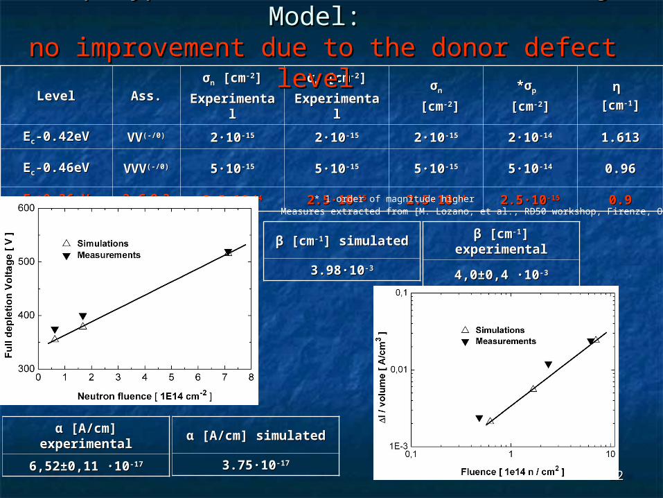
EEcc-0.42eV-0.42eV VVVV(-/0)(-/0) 22·10·10-15-15 22·10·10-15-15 22·10·10-15-15 22·10·10-14-14 1.6131.613
EEcc-0.46eV-0.46eV VVVVVV(-/0)(-/0) 55·10·10-15-15 55·10·10-15-15 55·10·10-15-15 55·10·10-14-14 0.960.96
EEvv+0.36eV+0.36eV ? C? CiiOOii?? 2.5·102.5·10-14-14 2.5·102.5·10-15-15 2.5·102.5·10-14-14 2.5·102.5·10-15-15 0.90.9
ββ [cm[cm-1-1] ] experimentalexperimental
4,04,0±0,4 ·10±0,4 ·10-3-3
ββ [cm[cm-1-1] simulated] simulated
3.983.98·10·10-3-3
* 1 order of magnitude higher
The p-type Three-Level Radiation Damage The p-type Three-Level Radiation Damage Model: Model:
no improvement due to the donor defect levelno improvement due to the donor defect level
αα [ [A/cm] simulatedA/cm] simulated
3.753.75·10·10-17-17
αα [ [A/cm] A/cm] experimentalexperimental
6,526,52±0,11 ·10±0,11 ·10-17-17
Measures extracted from [M. Lozano, et al., RD50 workshop, Firenze, Oct 2004]

1313
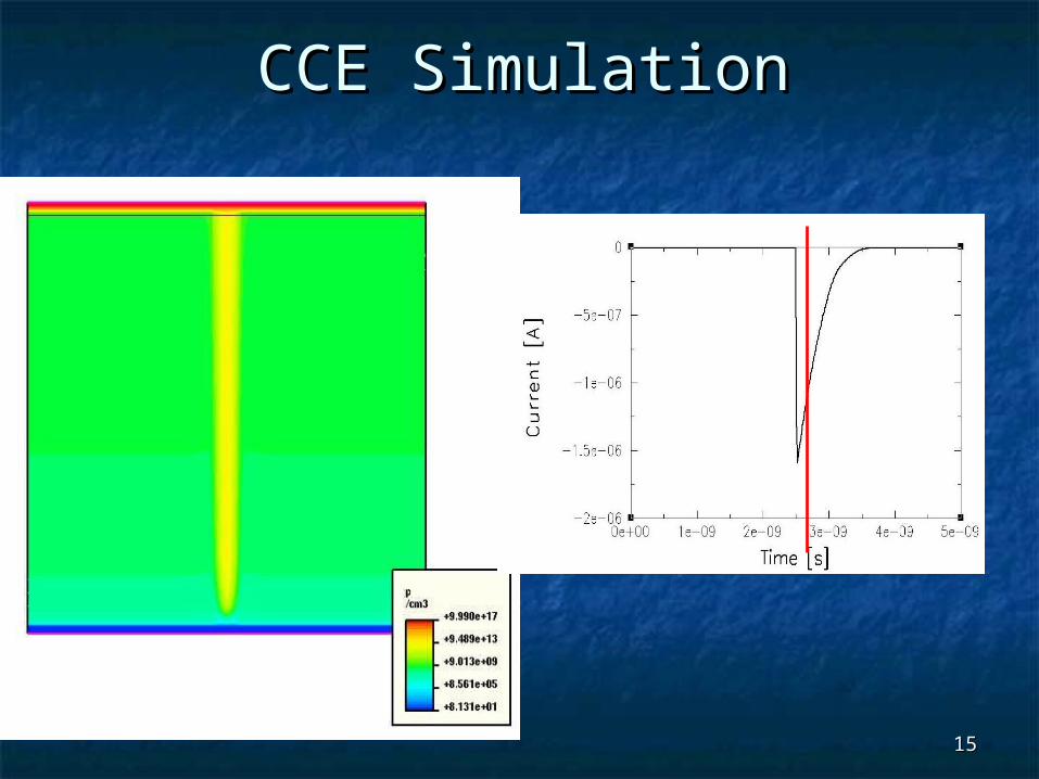
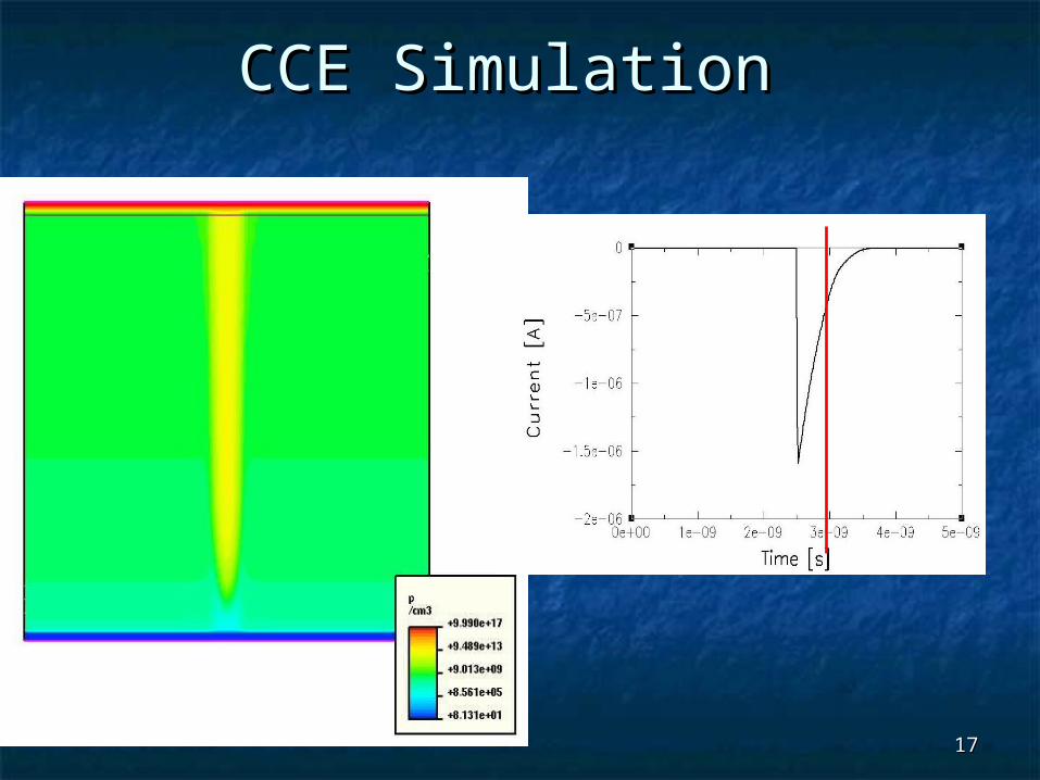
CCE SimulationCCE Simulation
MIP: 80 e-h pairs/ µmcylinder diameter = 2µm
dttIQ )(

1414
CCE SimulationCCE Simulation
1515
CCE SimulationCCE Simulation

1616
CCE SimulationCCE Simulation
1717
CCE Simulation CCE Simulation

1818
CCE SimulationCCE Simulation

1919
CCE SimulationCCE Simulation

2020
* Measurements from Allport, Casse et al. NIMA 501 (2003)
146-152
CCE vs BIAS voltage for n-type silicon
Simulation data well reproduce experimental* measure at the fluences of 1·1014 n/cm2 and 2.5·1014 n/cm2

2121
CCE vs BIAS for n-type
Simulation data at Fluence of 1·1015 n/cm2 and 1·1016 n/cm2
Problem: the diode collects charge also in the not depleted area.At a fluence of 5·1014:Simulated CCE = 75%Estimated (*) = 55%
(*) [Bloch et al, NIMA 517 (2004) 121-127]

2222
CCE vs BIAS for n-type
Discussion about the ISE T-CAD Recombination Time model
REF
eff
effdop
doppn
kT
E
effinkT
E
effip
effiSRH
N
NN
ETF
eppenn
nnpR
he
traptrap
1
)(
),(
minmaxmin
/
2,
2,
2,
/
eqheeff
/
1
Default parameters of the Scharfetter model:
NREF=1016 cm-3, γ=1, τmin=0, τmax(e) =3 µs, τmax(h) =10 µs
βe [10-16 cm2/ns]
βh [10-16 cm2/ns]
5.16 + 0.16 5.04 + 0.16
where
From RD50 status Report (2004):
change the NREF parameter in order to obtain the correct value of the recombination time(*) J.G.Fossum, D.S. Lee, Solid-State Electronics, vol.25,no.8 (1982).
2323
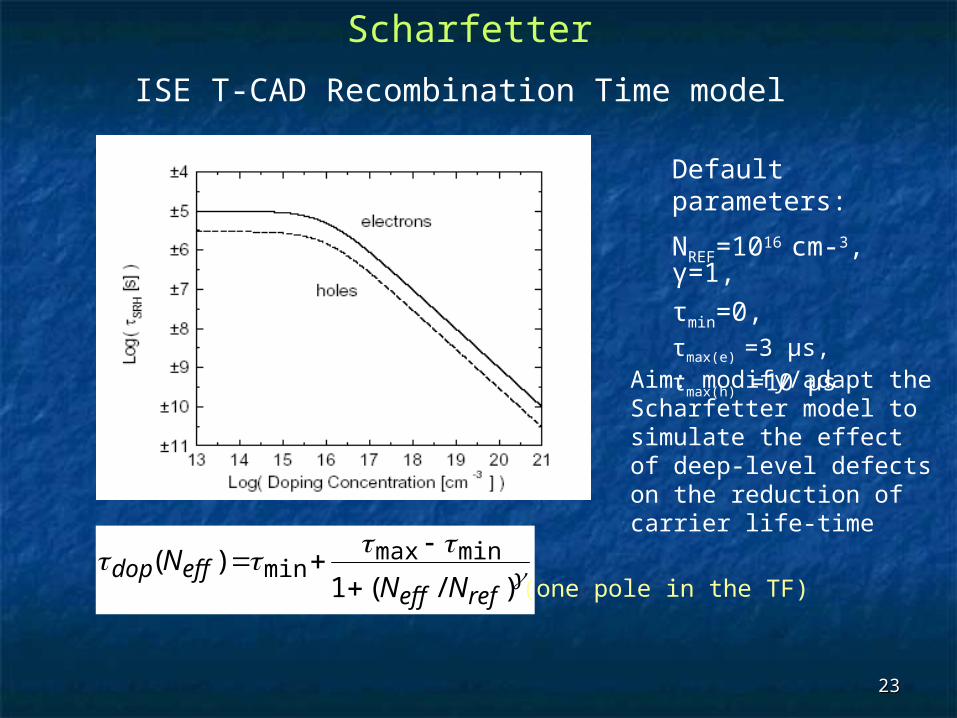
Scharfetter
ISE T-CAD Recombination Time model
Default parameters:
NREF=1016 cm-3, γ=1,
τmin=0, τmax(e) =3 µs, τmax(h) =10 µs
)/(1)( minmax
minrefeff
effdopNN
N
(one pole in the TF)
Aim: modify/adapt the Scharfetter model to simulate the effect of deep-level defects on the reduction of carrier life-time

2424
ConclusionsConclusions Irradiated diodes have been analyzed considering a
three levels simulation model for p-type and n-type Si substrates:
The two-level model for the p-type and the three-level for n-type fit experimental data for the Leakage Current and Full Depletion Voltage
The CiOi acceptor level for p-type silicon seems to be un-influential (at Room Temperature)
The three-level for n-type fits CCE experimental data only for fluences up to 2.5·1014 n/cm2.
Scharfetter recombination time empirical model can be eventually adapted to fit CCE experimental data at higher fluences (first good point @1e15 n/cm2).
Recommended