Technical Data
Condition Sensing SpecificationsBulletin Number 808, 836, 836T, 837, 840
Additional Resources
These documents contain additional information concerning related products from Rockwell Automation.
You can view or download publications at http://www.rockwellautomation.com/literature/. To order paper copies of technical documentation, contact your local Allen-Bradley distributor or Rockwell Automation sales representative.
Topic Page
Bulletin 840 Automatic Float Switches 3
Bulletin 836 Pressure Controls 5
Bulletin 836T Pressure Controls 11
Bulletin 808 Speed Switches 25
Bulletin 837 Temperature Controllers 30
Resource Description
Industrial Automation Wiring and Grounding Guidelines, publication 1770-4.1 Provides general guidelines for installing a Rockwell Automation industrial system.
Product Certifications website, http://www.ab.com Provides declarations of conformity, certificates, and other certification details.


3Rockwell Automation Publication -836-TD001A-EN-P
Specifications Bulletin 840 Automatic Float Switches
Technical DataTechnical TermsTank Operation — When the liquid in a tank reaches a preset lowlevel, the float switch will start a pump to begin filling the tank.When the liquid level reaches a preset high level, the float switch willstop the pump.
Sump Operation — Liquid is being collected in a sump. When theliquid reaches a preset high level, the float switch will start a pumpto empty the sump. When the liquid reaches a preset low level, thefloat switch will stop the pump.
Operating Force — Contact force required to trip the float switch.Operation depends on the type of switch, liquid, float, and floatoperator assembly.
Turbulence — Waves or agitation in the liquid. Excessive turbulencemay cause improper switch operation — for example, earlyswitching or switching between operating points.
Buoyancy — Force supporting the float equal in magnitude to theweight of the displaced liquid.
Theory of OperationBulletin 840 Float Switches provide automatic control for motorsthat pump liquids from a sump or into a tank. The switch must beinstalled above the tank or sump, and the float must be in the liquidfor the float switch to operate. Tank Operation: A float operatorassembly is attached to the float switch by a rod, chain or cable.The float switch is actuated based on the location of the float in theliquid. The float switch contacts are open when the float forces theoperating lever to the UP position. As the liquid level falls, the floatand operating lever move downward. When the float reaches apreset low level, the float switch contacts close, activating thecircuit and starting the motor. The contacts can directly activate amotor or provide input for a logic system to fill the tank. As theliquid level rises, the float and operating lever move upward. Whenthe float reaches a preset high level, the float switch contacts open,deactivating the circuit and stopping the motor. Sump Operation:Sump operation is opposite tank operation.
Figure 1Tank and Sump Operation
Tank Operation Sump Operation
Motor Stop
Motor StopMotor Start
Motor Start
Liquid LevelChange
Liquid LevelChange
Temperature Range (Switch)The temperature range for the switch mechanism at +32 °F (0 °C) orbelow is based on the absence of freezing moisture, water, or otherfluids that may solidify and impede the operation of the control.Temperature ratings are as follows:
Operating: –22…+150 °F (–30…+66 °C)
Storage: –22…+200 °F (–30…+93 °C)
Temperature Range (Float)The temperature range for the float mechanism at +32 °F (0 °C) orbelow is based on the absence of freezing moisture, water, or otherfluids that may solidify and impede the operation of the control.Temperature ratings are as follows:
Operating and Storage:–22…+200 °F (–30…+93 °C)
ConversionsBulletin 840 Styles A and B Float Switches are assembled for tankoperation but can be easily converted to sump operation. Style Aswitches can be changed from tank to sump operation by movingthe float rod to the opposite end of the double arm lever.
Styles B switches can be converted in either of the following ways: Remove the lever, turn the shaft 90° counterclockwise and replace
the lever in its original position.
Remove the lever and replace 180° from the original position.
Style D is for tank operation only. Style DS is for sump operationonly. These switches cannot be converted.
ContactsBulletin 840 Float Switches have a snap action mechanism forquick-make and quick-break contact operation. This featureprovides high snap-through forces once the mechanism hastraveled the required distance. See table below.
Maximum Contact Rating per Pole
AC — NEMA A600 DC — NEMA N300
Max. VAC Make Break Make Break
Max. VDC Make Break
120 60 A 6.0 A 7200V A 720V A — — —
240 30 A 3.0 A 7200V A 720V A 125 2.2 A 2.2 A
480 15 A 1.5 A 7200V A 720V A 250 1.1 A 1.1 A
600 12 A 1.2 A 7200V A 720V A — — —
Maximum Horsepower Ratings
Style
Single-PhaseAC
2- or 3-PhaseAC DC
115V 230V 115V
230-460-575V 32V 115V 230V
A — Tank orSump 1 1 — — .025 0.25 0.125
B — Tank orSump 1.5 3 — 2 — 1 1
D — Tank 1.5 2 2 3 0.25 0.5 0.5
DS — Sump 1.5 2 2 3 0.25 0.5 0.5
Contact Wiring Configurations
Style A (Contact Options)
N.C. N.C. N.C.N.O. N.O. N.O.
840-A1 840-A11 840-A12
2 N.O. 2 N.C.1 N.O. - 1 N.C. (Standard)
Style B Styles D & DS
1
L1 L2 L3 L1 L2 L3
T1 T2 T1 T2
2
3
4
1
2
3
4
Motor Motor
4 Rockwell Automation Publication -836-TD001A-EN-P
Bulletin 840 Automatic Float Switches Specifications
Approximate DimensionsApproximate Dimensions and Shipping WeightsDimensions in inches (millimeters). Dimensions are not intended tobe used for manufacturing purposes.
Type 1Mounting Bracket
3.5(88.9)
2.81(71.4)
3.75(95.3)
2.75(69.9)
3.00(76.2)
5.38(136.5)
2.00(50.8)
4.00(101.6)
1.75(44.5)
0.75(19.0)
2.00(50.8)
0.50(12.7)
0.28(7.10)
Dia. Mtg.Holes
Style A —Approximate Shipping Weight 4 lbs (1.8 kg)
4.56(115.9)
3.44(87.3)
5.0(127.0)
2.63(66.7)
2.88(73.0)
5.5(139.7)
Style B —Approximate Shipping Weight 3 lbs (1.4 kg)
5.75 Approx.(146)
Styles D and DS —Approximate Shipping Weight 2 lbs (0.9 kg)
Type 4
¾ in. Conduit Hub
Dia. Mtg. Holes
Styles A and B —Approximate Shipping Weight 4 lbs (1.8 kg)
5Rockwell Automation Publication -836-TD001A-EN-P
Specifications Bulletin 836 Pressure Controls
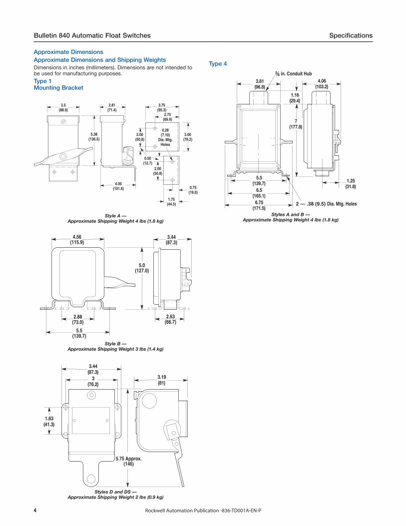
Technical DataTechnical TermsAdjustable operating range — Total span within which thecontacts can be adjusted to trip and reset.
Trip setting — Higher pressure setting at which value the contactstransfer from their normal state to a changed state.
Reset setting — Lower pressure setting at which value thecontacts return to their normal state.
Adjustable differential — Difference between the trip and resetvalues.
Minimum differential — When the differential is set to the lowestpressure difference between trip and reset.
Maximum differential — When the differential is set to the widestpressure difference between trip and reset.
Maximum occasional surge pressure — Maximum surge pressurethat can be applied to the actuator. Surges or transients can occurduring startup and shutdown of a machine or system. Expressed inmilliseconds, complex electronic instrumentation is required tomeasure the varying amplitude, frequency, and duration of this waveform. Extreme surges that occur approximately eight times in a 24-hour period are negligible.Maximum line pressure — Maximum sustained pressure that canbe applied to the bellows without permanent damage. The controlshould not be cycled at this pressure.
Positive pressure — Any pressure more than 0 psi. See Figure 2.
Trip setting — Increasing pressure setting when contacts changestate.
Reset setting — Decreasing pressure setting when contactsreturn to their normal state.
Vacuum (negative pressure) — Any pressure less than 0 psi,inches of Hg vacuum. See Figure 2.
Trip setting — Decreasing vacuum setting when contacts changestate.
Reset setting — Increasing vacuum setting when contacts returnto their normal state.
psi — Pounds per square inch. Devices listed are in gauge pressureunits which use atmospheric pressure as a reference. Atmosphericpressure at sea level is approximately 14.7 psi or 30 in. Hg.
Operating range adjustment acrew — This screw is used toadjust the trip setting by varying the force of the main spring.
Differential adjustment screw — This screw is used to adjust resetsetting by varying the force of the differential blade spring.
Pressure media — There are many types of pressure media thatare controlled. Examples include air, water, hydraulic fluids andother types of gases and liquids. The type of media and maximumsystem pressure will determine the type of actuator used for thepressure control application. See page 13-9.
Pressure connection — Common types of pressure connectionsused in control systems are 1/4 in. and 3/8 in. female pipe threads,and 7/16 in. — 20 SAE copper tubing.
Contact configuration — There are many types of contactconfigurations available. Bulletin 836 Style A and C pressurecontrols offer a wide variety of contact configurations for bothautomatic operation and manual reset. See page 13-14.
Figure 1Graphics to illustrate technical terms
0 psi Reference
100% Operating Range 100%
75%
50%
25%
Adju
stab
le O
pera
ting
Ran
dge
MinimumDifferential
MaximumDifferential
(Maximum ResetAdjustment)
30 in. Vacuum Mercury Reference
Trip Setting
Reset Setting(Minimum ResetAdjustment)
Adjustable Span
Incr
easi
ng P
ress
ure
psi
Max
imum
Occ
asio
nal
Surg
e Pr
essu
re
Max
imum
Lin
e Pr
essu
re
Adju
stab
leO
pera
ting
Angl
e
VAC
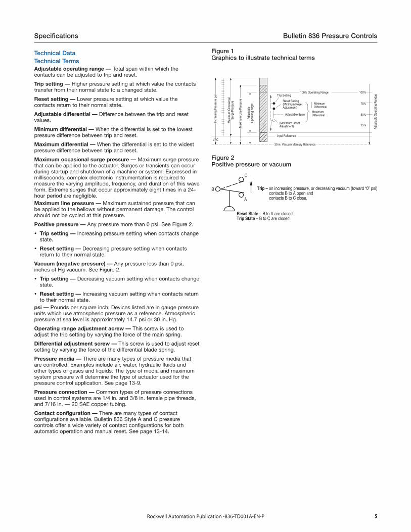
Figure 2Positive pressure or vacuum
Trip – on increasing pressure, or decreasing vacuum (toward “0” psi) contacts B to A open and contacts B to C close.
Reset State – B to A are closed.Trip State – B to C are closed.
C
A
B
6 Rockwell Automation Publication -836-TD001A-EN-P
Bulletin 836 Pressure Controls Specifications
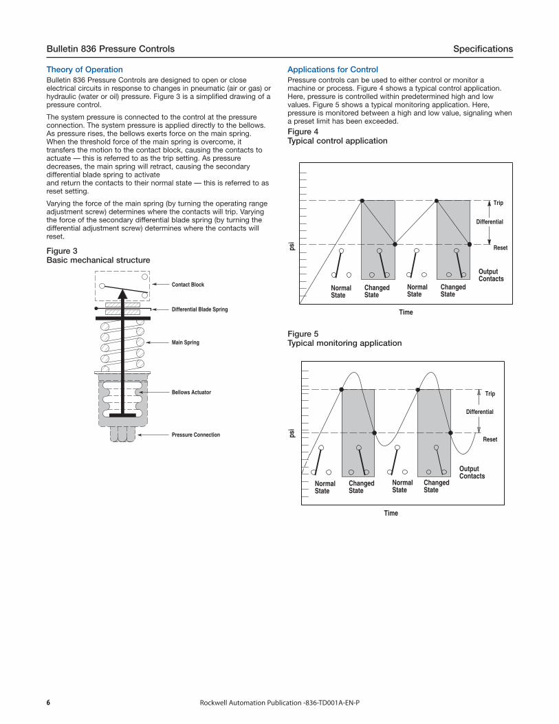
Figure 3Basic mechanical structure
Contact Block
Differential Blade Spring
Main Spring
Bellows Actuator
Pressure Connection
Applications for ControlPressure controls can be used to either control or monitor amachine or process. Figure 4 shows a typical control application.Here, pressure is controlled within predetermined high and lowvalues. Figure 5 shows a typical monitoring application. Here,pressure is monitored between a high and low value, signaling whena preset limit has been exceeded.
Figure 4Typical control application
Time
ChangedState
OutputContacts
NormalState
ChangedState
NormalState
psi
Trip
Differential
Reset
Figure 5Typical monitoring application
Theory of OperationBulletin 836 Pressure Controls are designed to open or closeelectrical circuits in response to changes in pneumatic (air or gas) orhydraulic (water or oil) pressure. Figure 3 is a simplified drawing of apressure control.
The system pressure is connected to the control at the pressureconnection. The system pressure is applied directly to the bellows.As pressure rises, the bellows exerts force on the main spring.When the threshold force of the main spring is overcome, ittransfers the motion to the contact block, causing the contacts toactuate — this is referred to as the trip setting. As pressuredecreases, the main spring will retract, causing the secondarydifferential blade spring to activateand return the contacts to their normal state — this is referred to asreset setting.
Varying the force of the main spring (by turning the operating rangeadjustment screw) determines where the contacts will trip. Varyingthe force of the secondary differential blade spring (by turning thedifferential adjustment screw) determines where the contacts willreset.
Time
ChangedState
OutputContacts
NormalState
ChangedState
NormalState
psi
Trip
Differential
Reset

7Rockwell Automation Publication -836-TD001A-EN-P
Specifications Bulletin 836 Pressure Controls
Control SettingsAllen-Bradley controls are designed for ease of setting to helpminimize installation time. Standard controls shipped from thefactory are set at the maximum operating range and minimumdifferential. By following this simple two-step process, the controlcan be set to the specific requirements for each application. SeeFigure 6.
Step 1 — Adjust trip settingThe trip setting is achieved by turning the operating rangeadjustment screw. Turn the range screw counterclockwise to lowerthe trip setting, or clockwise to raise the trip setting. Theapproximate trip setting is shown on the indicating scale.Note: Turning the operating range adjustment screw will changeboth the trip and reset settings in virtually equal increments.
Step 2 — Adjust reset settingThe reset setting is achieved by turning the differential adjustmentscrew counterclockwise to increase the differential, or clockwise todecrease the differential.Note: Adjusting the differential has little or no affect upon the tripsetting.
Figure 6Trip and reset adjustment
Finger-Safe Contact Block Shield MeetsIEC 529/IP2X & CSA
Clear Contact InspectionCover
Terminal A
Indicating Scale (psi)(Approximate Trip Setting)
DifferentialAdjustment Screw(Reset Pressure)
Differential Reference Scale
Indicating Scale (Metric)(Approximate Trip Setting)
Operating RangeAdjustment Screw
(Trip Pressure)
Terminal C
Test Button (Optional)
Terminal B
Repeat Accuracy and Mechanical Life
The design and construction of Bulletin 836 Styles A and C controlsprovide a typical repeat accuracy of + 0.5% or better. Repeataccuracy is based on percent of maximum range, evaluated fromtest data and calculated using the formula per ICS 2-225 standards.
Repeat accuracy and mechanical life of bellows type controls isgraphically illustrated in Figure 7. For general applications, controlsselected where the contacts operate between 30…80% of theoperating range and where the maximum line and surge pressuresdo not exceed the specified values will provide excellent life andrepeat accuracy. For more specific applications, it is important tonote that the controls are designed to operate below or abovethese values. However, there may be a small trade-off between thefactors of repeat accuracy and mechanical life.
Figure 7Repeat accuracy versus mechanical life graph
V AC
Usable area of range that provides best repeat accu-racy and possible slightly decreased operating life.
Usable area of range that provides longest lifeand possibly slightly reduced repeat accuracy.
0 psi Reference
Adju
stab
leO
pera
ting
Ran
ge
Adju
stab
le O
pera
ting
Ran
ge
30 in. Hg ReferenceImproved Life/Accuracy
RepeatAccuracy(BellowsControls)
Life(BellowsControls
Only)In
crea
sing
Pre
ssur
e ps
i
30%
80%
100%
75%
50%
25%
RecomendedSelection Rangefor GeneralApplications
8 Rockwell Automation Publication -836-TD001A-EN-P
Bulletin 836 Pressure Controls Specifications
Standard ContactsSnap-action contact operationContact blocks are single-pole, double-throw and can be wired toopen or close on increasing or decreasing pressures.
Non-inductive ratings5 A, 240V3 A, 600V
Control circuit ratingsAC - 125 VA, 24…600VDC - 57.5 VA, 115…230V
Standard Contact Wiring ConfigurationsSingle-pole double throw
Vacuum (Negative Pressure)Positive Pressure
A
C
B
A
C
B
Note: NEMA does not rate contacts to switch low voltage andcurrent.Bulletin 836 Styles A and C Pressure Controls are supplied withsilver contacts. The devices are designed to deliver high-force snapaction to the contacts. This provides exceptional contact fidelity at24V DC I/O card current level entry when the control is protected ina suitable enclosure for the surrounding environment.
Special ControlsA large number of unlisted catalog modifications and completedevices are available for specific and OEM applications.
Special controls and modification service is available to meet manyapplications unique to the OEM market.
Please contact your local Rockwell Automation sales office or Allen-Bradley distributor for assistance with specific modified controls andaccessories.
Temperature RangeTemperature range at +32 °F (0 °C) or below is based on theabsence of freezing moisture, water, or other fluids that may solidifyand impede operation of the control. Temperature ratings are asfollows:
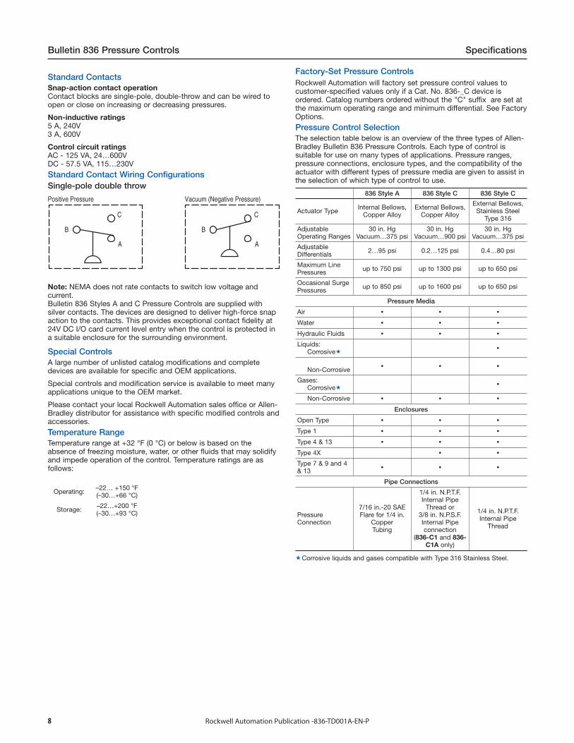
Factory-Set Pressure ControlsRockwell Automation will factory set pressure control values tocustomer-specified values only if a Cat. No. 836-_C device isordered. Catalog numbers ordered without the "C" suffix are set atthe maximum operating range and minimum differential. See FactoryOptions.
Pressure Control SelectionThe selection table below is an overview of the three types of Allen-Bradley Bulletin 836 Pressure Controls. Each type of control issuitable for use on many types of applications. Pressure ranges,pressure connections, enclosure types, and the compatibility of theactuator with different types of pressure media are given to assist inthe selection of which type of control to use.
Operating: –22… +150 °F(–30…+66 °C)
Storage: –22…+200 °F(–30…+93 °C)
836 Style A 836 Style C 836 Style C
Actuator Type Internal Bellows,Copper Alloy
External Bellows,Copper Alloy
External Bellows,Stainless Steel
Type 316
AdjustableOperating Ranges
30 in. HgVacuum…375 psi
30 in. HgVacuum…900 psi
30 in. HgVacuum…375 psi
AdjustableDifferentials 2…95 psi 0.2…125 psi 0.4…80 psi
Maximum LinePressures up to 750 psi up to 1300 psi up to 650 psi
Occasional SurgePressures up to 850 psi up to 1600 psi up to 650 psi
Pressure Media
Air
Water
Hydraulic Fluids
Liquids:Corrosive
Non-Corrosive
Gases:Corrosive
Non-Corrosive
Enclosures
Open Type
Type 1
Type 4 & 13
Type 4X
Type 7 & 9 and 4& 13
Pipe Connections
PressureConnection
7/16 in.-20 SAEFlare for 1/4 in.
CopperTubing
1/4 in. N.P.T.F.Internal Pipe
Thread or3/8 in. N.P.S.F.Internal Pipeconnection
(836-C1 and 836-C1A only)
1/4 in. N.P.T.F.Internal Pipe
Thread
Corrosive liquids and gases compatible with Type 316 Stainless Steel.
9Rockwell Automation Publication -836-TD001A-EN-P
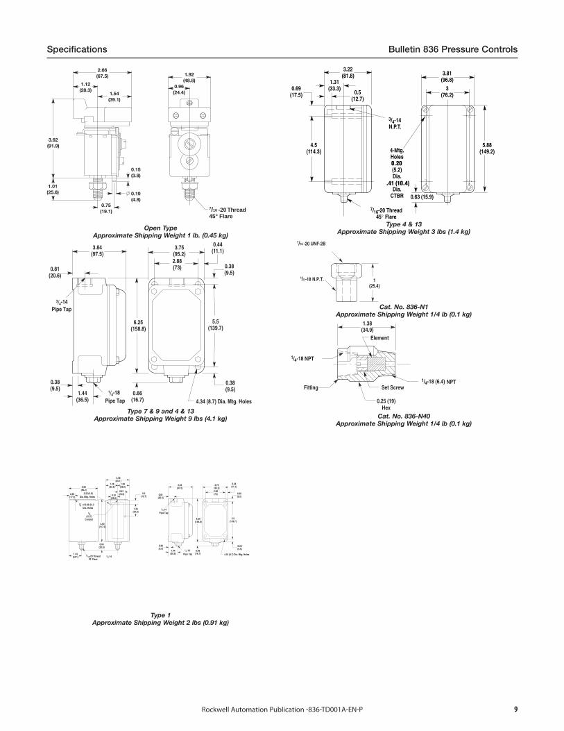
Specifications Bulletin 836 Pressure Controls
7/16 -20 Thread45° Flare
Open TypeApproximate Shipping Weight 1 lb. (0.45 kg)
3/4-14
1/4-18
4.34 (8.7) Dia. Mtg. Holes
Pipe Tap
Pipe Tap
Type 7 & 9 and 4 & 13Approximate Shipping Weight 9 lbs (4.1 kg)
3/4-14
3/4-14
1/4-18
4.34 (8.7) Dia. Mtg. Holes
Dia. Mtg. Holes
Dia. Holes
Pipe Tap
Pipe Tap
Conduit
ThreadFlare
Type 1Approximate Shipping Weight 2 lbs (0.91 kg)
Type 4 & 13Approximate Shipping Weight 3 lbs (1.4 kg)
7/16 -20 UNF-2B
1/4 -18 N.P.T.
Cat. No. 836-N1Approximate Shipping Weight 1/4 lb (0.1 kg)
Fitting Set Screw
Hex
NPT
NPT
Element
Cat. No. 836-N40Approximate Shipping Weight 1/4 lb (0.1 kg)
10 Rockwell Automation Publication -836-TD001A-EN-P
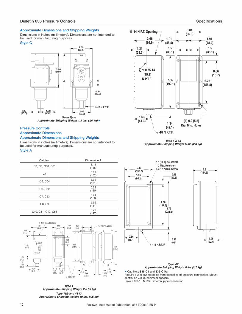
Bulletin 836 Pressure Controls Specifications
Cat. No. Dimension A
C2, C3, C60, C61 6.11(155)
C4 5.99(152)
C5, C64 5.94(151)
C6, C62 6.29(160)
C7, C63 6.24(158)
C8, C9 5.56(141)
C10, C11, C12, C65 5.78(147)
3.25(62.6)
4.63(117.5)
0.69(17.5)
of 0.88(22.2)Dia.Hole
1.75(44.4)
to2.69
(68.3)1.34
(34.1)
2.56(65.1)
1.63(41.3)
1.38(34.9)
1.28(32.5)
1.28(32.5)
¼ -18 N.P.T.F.
8.63(219.1)
2.75(69.8)
¾ -14 N.P.T. Opening
1.88(47.6)
4.25(107)
2.72(69.1)
5.44(138.2)
10.25(260.4)
½ (12.7) Conduit Opening
CL
Conduit
Type 1Approximate Shipping Weight 2.0 (.9 kg)
Type 7&9 and 4&13Approximate Shipping Weight 10 lbs. (4.5 kg)
(4)-0.2 (5.2)Dia. Mtg. Holes
of 0.75-14(19.2)
N.P.T.F.
¼ -18 N.P.T.F.
¾ -14 N.P.T. Opening
Type 4 & 13Approximate Shipping Weight 5 lbs (2.3 kg)
¼ - 18 N.P.T. F.
0.5 (12.7) Dia. CTBR2 Mtg. Holes for
0.5 (12.7) Dia. Screw
Type 4XApproximate Shipping Weight 6 lbs (2.7 kg)
Cat. No.s 836-C1 and 836-C1A:Require a 2 in. swing radius from centerline of pressure connection. Mountcontrol on 7/8 in. minimum spacersHave a 3/8-18 N.P.S.F. internal pipe connection
Pressure ControlsApproximate DimensionsApproximate Dimensions and Shipping WeightsDimensions in inches (millimeters). Dimensions are not intended tobe used for manufacturing purposes.
Style A
Approximate Dimensions and Shipping WeightsDimensions in inches (millimeters). Dimensions are not intended tobe used for manufacturing purposes.
Style C2.50
(63.5)
2.06(52.3)
1.78(45.2)
1.20(30.5)
3.86(98.0)
0.94(23.8)
A
¼-18 N.P.T.F
Open TypeApproximate Shipping Weight 1.3 lbs. (.60 kg)
11Rockwell Automation Publication -836-TD001A-EN-P
Specifications Bulletin 836T Pressure Controls
Technical DataTechnical TermsAdjustable operating range — Total span within which thecontacts can be adjusted to trip and reset.
Trip setting — Higher pressure setting at which value the contactstransfer from their normal state to a change state.
Reset setting — Lower pressure setting at which value thecontacts return to their normal state.
Adjustable differential — Difference between the trip and resetvalues
Minimum differential — When the differential is set to the lowestpossible difference between trip and reset.
Maximum differential — When the differential is set to the highestpossible difference between trip and reset.
Max. occasional surge pressure — Maximum surge pressure thatcan be applied to the actuator. Surges or ransients can occur duringstart-up and shut-down of a machine or system. Expressed inmilliseconds, complex electronic instrumentation is required tomeasure the varying amplitude, frequency, and duration of this waveform. Extreme surges that occur approximately 8 times in a 24-hourperiod are negligible.
Maximum line pressure — Maximum sustained pressure that canbe applied to the actuator without permanent damage. The controlshould not be cycled at this pressure. Note: Does not apply topiston type controls.psi — Pounds per square inch gauge (positive pressure). Deviceslisted are in gauge pressure units which use atmospheric pressureas a reference. Atmospheric pressure at sea level is approximately14.7 psi or 30 in. Hg.
Vacuum — Inches of mercury (in. Hg) vacuum (negative pressure).
Operating range adjustment screw — This screw is used to adjustthe trip setting by varying the force of the main spring.
Differential adjustment screw — This screw is used to adjust resetsetting by varying the force of the differential blade spring.
Pressure media — There are many types of pressure media thatcan be controlled. Examples include air, water, hydraulic fluids, andother types of gases and liquids. The type of media and themaximum system pressure will determine the type of actuator usedfor the pressure control application. See page 13-32.
Pressure connection — Common standard types of pressureconnections used in control systems are 1/4 in. and 3/8 in. N.P.T.F.female pipe threads. SAE 7/16 and SAE 9/16 O-ring boss seals arealso available (piston versions only).
Contact configuration — Bulletin 836T controls are available witheither a 2-circuit or 4-circuit contact block. See Contacts.
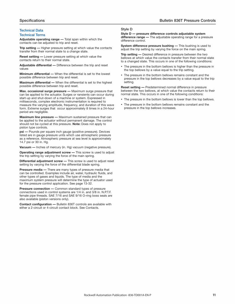
Style DStyle D — pressure difference controls adjustable systemdifference range — The adjustable operating range for a pressuredifference control.
System difference pressure bushing — This bushing is used toadjust the trip setting by varying the force on the main spring.
Trip setting — Desired difference in pressure between the twobellows at which value the contacts transfer from their normal stateto a changed state. This occurs in one of the following conditions:
The pressure in the bottom bellows is higher than the pressure inthe top bellows by a value equal to the trip setting.
The pressure in the bottom bellows remains constant and thepressure in the top bellows decreases by a value equal to the tripsetting.
Reset setting — Predetermined normal difference in pressurebetween the two bellows, at which value the contacts return to theirnormal state. This occurs in one of the following conditions:
The pressure in the bottom bellows is lower than the top bellows.
The pressure in the bottom bellows remains constant and thepressure in the top bellows increases.
12 Rockwell Automation Publication -836-TD001A-EN-P
Bulletin 836T Pressure Controls Specifications
0 psi Reference
100% Operating Range 100%
75%
50%
25%
Adju
stab
le O
pera
ting
Ran
dge
MinimumDifferential
MaximumDifferential
(Maximum ResetAdjustment)
Trip Setting
Reset Setting(Minimum ResetAdjustment)
Adjustable Span
Incr
easi
ng P
ress
ure
psi
Max
imum
Occ
asio
nal
Surg
e Pr
essu
re
Max
imum
Lin
e Pr
essu
re
Adju
stab
leO
pera
ting
Angl
e
VAC30 in. Hg Vacuum Reference
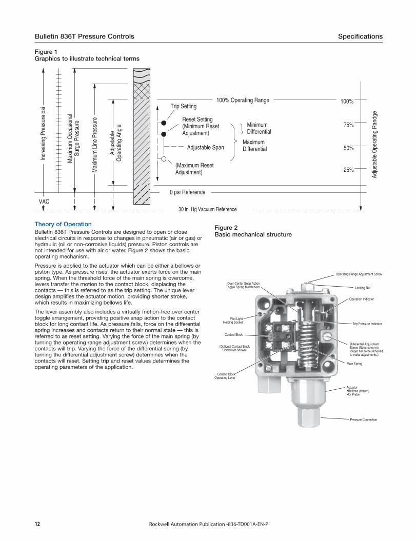
Theory of OperationBulletin 836T Pressure Controls are designed to open or closeelectrical circuits in response to changes in pneumatic (air or gas) orhydraulic (oil or non-corrosive liquids) pressure. Piston controls arenot intended for use with air or water. Figure 2 shows the basicoperating mechanism.
Pressure is applied to the actuator which can be either a bellows orpiston type. As pressure rises, the actuator exerts force on the mainspring. When the threshold force of the main spring is overcome,levers transfer the motion to the contact block, displacing thecontacts — this is referred to as the trip setting. The unique leverdesign amplifies the actuator motion, providing shorter stroke,which results in maximizing bellows life.
The lever assembly also includes a virtually friction-free over-centertoggle arrangement, providing positive snap action to the contactblock for long contact life. As pressure falls, force on the differentialspring increases and contacts return to their normal state — this isreferred to as reset setting. Varying the force of the main spring (byturning the operating range adjustment screw) determines when thecontacts will trip. Varying the force of the differential spring (byturning the differential adjustment screw) determines when thecontacts will reset. Setting trip and reset values determines theoperating parameters of the application.
Figure 2Basic mechanical structure
Contact Block
Differential AdjustmentScrew (Note: cover nolonger has to be removedto make adjustments.)
Main Spring
Trip Pressure Indicator
Operation Indicator
Locking Nut
Opersting Range Adjustment Screw
ActuatorBellows (shown)Or Piston
Pressure Connection
Over-Center Snap ActionToggle Spring Mechanism
Pilot LightHolding Socket
(Optional Contact BlockShield Not Shown)
Contact BlockOperating Lever
Figure 1Graphics to illustrate technical terms

13Rockwell Automation Publication -836-TD001A-EN-P
Specifications Bulletin 836T Pressure Controls
Applications for ControlPressure controls can be used to either control or monitor amachine or process. Figure 3 shows a typical control application.Here, pressure is controlled within predetermined high and lowvalues. Figure 4 shows a typical monitoring application. Here,pressure is monitored between a high and low value, signaling whena preset limit has been exceeded.
Figure 3Typical control application
Time
ChangedState
OutputContacts
NormalState
ChangedState
NormalState
psi
Trip
Differential
Reset
Figure 4Typical monitoring application
Time
ChangedState
OutputContacts
NormalState
ChangedState
NormalState
psi
Trip
Differential
Reset
Control Setting — Style T Pressure ControlsAllen-Bradley controls are designed for ease of setting to helpminimize installation time. Standard pressure controls shipped fromthe factory are set at the maximum operating range and minimumdifferential. By using a pressure gauge and following these simpledirections, the control can be set to the specific requirements foreach application. See Figure 5.Step 1 — Adjust trip settingThe trip setting is controlled by the operating range adjustmentscrew and is adjusted externally. After loosening the lock nut, thetrip setting is set by turning the operating range adjustment screwcounterclockwise to lower the trip setting or clockwise to raise thetrip setting. The approximate trip setting is shown on the indicatingscale. When the proper setting is reached, simply tighten the locknut.Note: Turning the operating range adjustment screw will cause boththe trip and reset settings to change in virtually equal increments.
Step 2 — Adjust reset settingThe reset setting is controlled by an external differential adjustmentscrew. The reset setting is set by turning the differential adjustmentscrew clockwise to increase the differential or counterclockwise todecrease the differential. Note: Adjusting the differential has little or no affect on the tripsetting.
Figure 5Trip and reset adjustment for pressure controls
Indicating Scale(Approximate Trip Setting)
OptionalPilot Light
Opersting RangeAdjustment Screw(Trip Pressure)
Locking Nut
Differential Adjustment Screw(Reset Pressure)
Optional Finger-Safe Contact BlockMeets IEC 529/Ip2X & CSA
Control Setting — Style D Pressure Difference ControlsStandard pressure difference controls shipped from the factory areset at the maximum adjustable difference range and minimumdifferential. Remove the front cover and use a pressure gauge tomake the following adjustments. See Figure 6.
Step 1 — Adjust trip setting (difference pressure)The trip setting is controlled by the system difference pressurebushing and is adjusted internally. With no pressure (open toatmosphere) applied to top bellows, apply a constant pressure tobottom bellows equal to the desired difference in pressure at whichthe contacts are to trip. Insert a 1/8 in. diameter rod into a hole inthe bushing and turn bushing to the left. Continue to turn bushinguntil the mechanism trips; circuit 1-2 will open. At this value, the tripsetting is set at the pressure which is being applied to the bottombellows.Note: Turning the system difference pressure bushing will causeboth the trip and reset settings to change in virtually equalincrements.
Step 2 — Adjust reset setting (differential pressure)The reset setting is controlled by differential adjustment screw (thisadjustment can be made with the cover on). The reset setting isadjusted by turning the differential adjustment screw clockwise toincrease the differential or counterclockwise to decrease thedifferential.Note: Adjusting the differential has little or no affect upon the tripsetting (difference pressure).
14 Rockwell Automation Publication -836-TD001A-EN-P
Bulletin 836T Pressure Controls Specifications
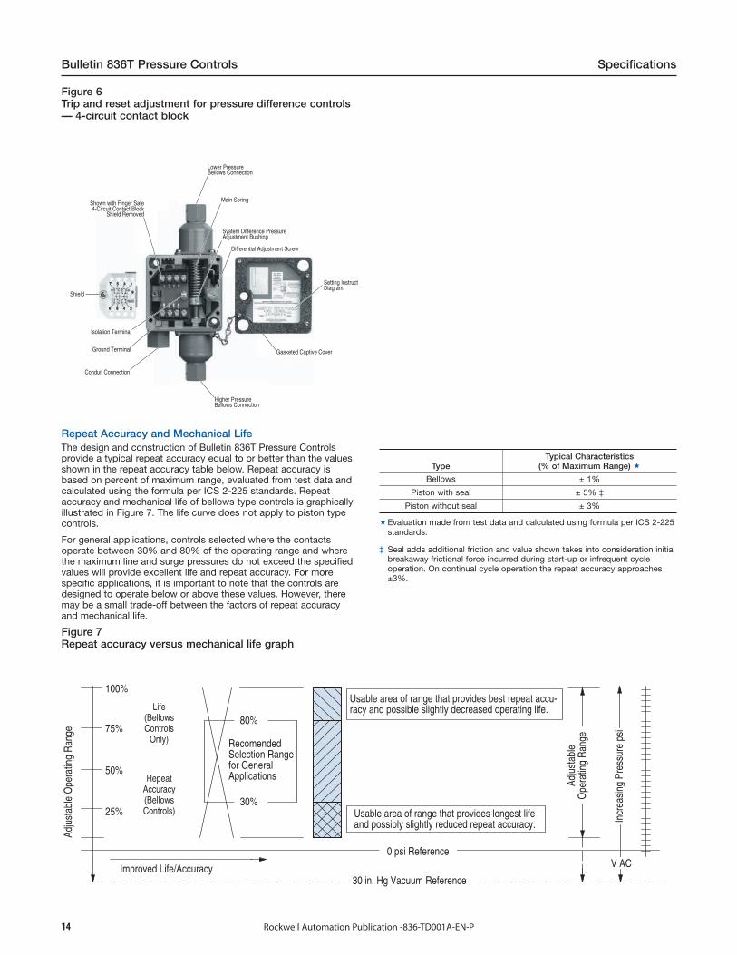
Figure 6Trip and reset adjustment for pressure difference controls— 4-circuit contact block
Main Spring
System Difference PressureAdjustment Bushing
Differential Adjustment Screw
Setting InstructiDiagram
Conduit Connection
Ground Terminal
Isolation Terminal
Shield
Gasketed Captive Cover
Higher PressureBellows Connection
Lower PressureBellows Connection
Shown with Finger Safe4-Circuit Contact Block
Shield Removed
Repeat Accuracy and Mechanical LifeThe design and construction of Bulletin 836T Pressure Controlsprovide a typical repeat accuracy equal to or better than the valuesshown in the repeat accuracy table below. Repeat accuracy isbased on percent of maximum range, evaluated from test data andcalculated using the formula per ICS 2-225 standards. Repeataccuracy and mechanical life of bellows type controls is graphicallyillustrated in Figure 7. The life curve does not apply to piston typecontrols.
For general applications, controls selected where the contactsoperate between 30% and 80% of the operating range and wherethe maximum line and surge pressures do not exceed the specifiedvalues will provide excellent life and repeat accuracy. For morespecific applications, it is important to note that the controls aredesigned to operate below or above these values. However, theremay be a small trade-off between the factors of repeat accuracyand mechanical life.
Figure 7Repeat accuracy versus mechanical life graph
V AC
Usable area of range that provides best repeat accu-racy and possible slightly decreased operating life.
Usable area of range that provides longest lifeand possibly slightly reduced repeat accuracy.
0 psi Reference
Adju
stab
leO
pera
ting
Ran
ge
Adju
stab
le O
pera
ting
Ran
ge
30 in. Hg Vacuum ReferenceImproved Life/Accuracy
RepeatAccuracy(BellowsControls)
Life(BellowsControls
Only)
Incr
easi
ng P
ress
ure
psi
30%
80%
100%
75%
50%
25%
RecomendedSelection Rangefor GeneralApplications
TypeTypical Characteristics
(% of Maximum Range)
Bellows ± 1%
Piston with seal ± 5% ‡
Piston without seal ± 3%
Evaluation made from test data and calculated using formula per ICS 2-225standards.
‡ Seal adds additional friction and value shown takes into consideration initialbreakaway frictional force incurred during start-up or infrequent cycleoperation. On continual cycle operation the repeat accuracy approaches±3%.

15Rockwell Automation Publication -836-TD001A-EN-P
Specifications Bulletin 836T Pressure Controls
Conversion Factors (Rounded)
psi x 703.1 = mm/H2Opsi x 27.68 = in. H2Opsi x 51.71 = mm/Hgpsi x 2.036 = in. Hg
psi x 0.0703 = kg/cm2
psi x 0.0689 = barpsi x 68.95 = mbar
psi x 6895 = Papsi x 6.895 = kPa
Note:psi - pounds per square inch (gauge).H2O at 39.2 °FHg at 32 °F
Mounting without Removing CoverBulletin 836T controls can be mounted without removing the frontcover. This helps prevent foreign materials from entering the openedenclosure during the interval between mounting and wiring of thecontrol.
Factory Set Pressure ControlsRockwell Automation will factory set pressure controls to customerspecified values only if a Cat. No. 836T-__C device is selected.Unspecified pressure controls (cat. nos. without the "C" suffix)shipped from the factory are set at the maximum operating rangeand minimum differential. See Factory-Set Pressure Controls, page13-43.
Temperature RangeThe temperature range at +32 °F (0 °C) or below is based on theabsence of freezing moisture, water, or other fluids that may solidifyand impede the operation of the control. Temperature ratings:
Operating: –22… +150 °F(–30…+66 °C)
Storage: –22…+200 °F(–30…+93 °C)
ContactsBulletin 836T controls feature 2- and 4-circuit contact blocks foradded control circuit flexibility. Two-circuit contact blocks have onenormally open contact and one normally closed contact and may bearranged for single-pole double-throw operation or separate circuitoperation having the same polarity. Four-circuit contact blocks maybe arranged for double-pole double-throw operation or separatecircuit operation having the same polarity.
2 Circuit Contact Ratings
MaximumOperational Volts Ue
Utilization Category Rated Operational Currents
IEC NEMA Volts Ue Make Break
AC 600 AC-15 A600
120…600 7200 VA 720 VA
72…120 60 A 720 VA
24…72 60 A 10 A
DC 600 DC-13 - 115…600 50 VA 50 VA
4 Circuit Contact Ratings
MaximumOperational Volts Ue
Utilization Category Rated Operational Currents
IEC NEMA Volts Ue Make Break
AC 240 AC-15 B300 120…240 3600 VA 360 VA
DC 250 DC-13 R300 125…250 28 VA 28 VA
Note: NEMA does not rate contacts to switch low voltage andcurrent. Bulletin 836T Styles T and D Pressure Controls are suppliedwith silver contacts. The devices are designed to deliver high forcesnap action to the contacts. This provides exceptional contactfidelity at 24V DC I/O card current level entry when the integrity ofthe enclosure is maintained.
Contact Wiring Configurations2-Circuit Contact Blocks
Positive Pressure Vacuum Pressure
Trip — on increasing pressure, contacts1-2 openand 3-4 close
Trip — on increasing pressure, contacts3-4 openand 1-2 close
4-Circuit Contact Blocks
Positive Pressure Vacuum Pressure
Trip — on increasing pressure, contacts1-2 and 5-6 openand 3-4 and 7-8 close
Trip — on increasing pressure, contacts3-4 and 7-8 openand 1-2 and 5-6 close
IsolatedTerminal
IsolatedTermina
Note: Cicuits A and B are electrically isolated from one another.A or C circuits must be the same polarity.
BA
BA
Figure 8Removable paint mask
Cover with Transparent Mask and Instruction Label in Place
Cover with Mask Partially Removed

16 Rockwell Automation Publication -836-TD001A-EN-P
Bulletin 836T Pressure Controls Specifications
Nameplate with Removable Paint MaskThe masks are convenient for the many users who repaint controlsto match the machine or color code equipment. Saves costly time-consuming hand masking necessary so as not to conceal productfunctional specifications and approval listings. This feature isstandard on most controls at no additional cost. The paint maskfeature cannot be supplied on controls with pilot lights. They arealso not available on those devices where it is necessary to removethe mask and add suffix modifications to the catalog number orspecific customer identification in the space provided.
Pressure Control SelectionThe selection table below is an overview of the five types of Bulletin836T Pressure Controls Rockwell Automation offers. Each type ofcontrol is suitable for use on many types of applications. Pressureranges, pressure connections, enclosure types, and thecompatibility of the actulator with different types of pressure mediaare given to assist in the selection of which type of control to use.
836T
Actuator Type Copper AlloyBellows
Type 316Stainless
Steel Bellows
Piston TypeWithout Seal
Piston TypeWith Seal
Adjustableoperating
ranges
30 in. Hgvacuum…650
psi
30 in. Hgvacuum…375
psi40…5000 psi 80…5000 psi
Adjustabledifferentials 2…125 psi 2…90 psi 20…650 psi 40…650 psi
Maximum linepressures
up to 1300psi up to 600 psi ⎯ ⎯
Occasionalsurge
pressures
up to 1600psi up to 600 psi up to 15 000
psiup to 15 000
psi
Pressure Media
Air
Water
Hydraulicfluids
Corrosiveliquids
Non-corrosiveliquids
Corrosivegases
Non-corrosivegases
Enclosures
Type 1, 4 & 13
Type 7 & 9and 4 & 13,
IP66
Pipe Connections
Standardpressure
connection
1/4 in. N.P.T.F.female pipe
thread
1/4 in. N.P.T.F.female pipe
thread
3/8 in. N.P.T.F.female pipe
threadSAE 7/16-20
UNF-2Bthread O-ring
boss sealSAE 9/16-18
UNF-2Bthread O-ring
boss seal
3/8 in. N.P.T.F.female pipe
threadSAE 7/16-20
UNF-2Bthread O-ring
boss sealSAE 9/16-18
UNF-2Bthread O-ring
boss seal
Corrosive liquids and gases must be compatible with Type 316 StainlessSteel Bellows.
Note: Pressure difference controls are supplied with either copper alloy orstainless steel bellows. See Product Selection on page 13-38 and page 13-39for details.

17Rockwell Automation Publication -836-TD001A-EN-P
Specifications Bulletin 836T Pressure Controls
Wiring DiagramsBulletin 836T 5-Pin Mini-Type Receptacle Option Wiring Reference(J1 Wiring)(See applicable codes and laws)
Without Pilot Light
Suffix X19
SAME POLARITY
RECEPTACLE PINS
PRESSURE: CIRCUIT 1-2 (PINS 1&5) OPENS ON RISING PRESSUREVACUUM: CIRCUIT 3-4 (PINS 4 & 2) OPENS ON INCREASING VACUUM (TOWARD 30 in. HG)
PIN/WIRE CODE 1= White 2= Red 3= Green 4= Orange 5= Black
With Pilot Light
Suffix X21X9
WITH NEON GLOW PILOT LIGHT 120V AC ONLY PILOT LIGHT WIRED ACROSS CIRCUIT1-2 (PINS 1 & 5)
SAME POLARITY
RECEPTACLE PINS
PIN/WIRE CODE 1= White 2= Red 3= Green 4= Orange 5= Black
PRESSURE: CIRCUIT 1-2 (PINS 1&5) OPENS ON RISING PRESSUREVACUUM: CIRCUIT 3-4 (PINS 4 & 2) OPENS ON INCREASING VACUUM (TOWARD 30 in. HG)
PIN/WIRE CODE 1= White 2= Red 3= Green 4= Orange 5= Black
PRESSURE: CIRCUIT 1-2 (PINS 1 & 5) OPENS ON RISING PRESSUREVACUUM: CIRCUIT 3-4 (PINS 4 & 2) OPENS ON INCREASING VACUUM (TOWARD 30 in. HG)
Suffix X21X15WITH LED PILOT LIGHT 24V DC ONLY PILOT LIGHT WIRED ACROSS CIRCUIT1-2 (PINS 1 & 5)
SAME POLARITY
RECEPTACLE PINS
Suffix X22X9WITH NEON GLOW PILOT LIGHT 120V AC ONLY PILOT LIGHT WIRED ACROSS CIRCUIT3-4 (PINS 4 & 2)
SAME POLARITY
RECEPTACLE PINS
PIN/WIRE CODE 1= White 2= Red 3= Green 4= Orange 5= Black
PRESSURE: CIRCUIT 1-2 (PINS 1 & 5) OPENS ON RISING PRESSUREVACUUM: CIRCUIT 3-4 (PINS 4 & 2) OPENS ON INCREASING VACUUM (TOWARD 30 in. HG)
PIN/WIRE CODE 1= White 2= Red 3= Green 4= Orange 5= Black
PRESSURE: CIRCUIT 1-2 (PINS 1 & 5) OPENS ON RISING PRESSUREVACUUM: CIRCUIT 3-4 (PINS 4 & 2) OPENS ON INCREASING VACUUM (TOWARD 30 in. HG)
SAME POLARITY
RECEPTACLE PINS
Suffix X22X15WITH LED PILOT LIGHT 24V DC ONLY PILOT LIGHT WIRED ACROSS CIRCUIT3–4 (PINS 4 & 2)
The pilot lights shown in these diagrams are wired across the terminals andin series with the load. Pilot light is OFF when the load is energized, ONwhen the load is de-energized. For simultaneous energization of the loadand pilot light, or other optional wiring configurations, consult your localRockwell Automation sales office or Allen-Bradley distributor. You may onlyselect ONE wiring configuration per device.
‡ Note pilot light polarity.§ X22 not available with 4-circuit pressure controls.
18 Rockwell Automation Publication -836-TD001A-EN-P
Bulletin 836T Pressure Controls Specifications
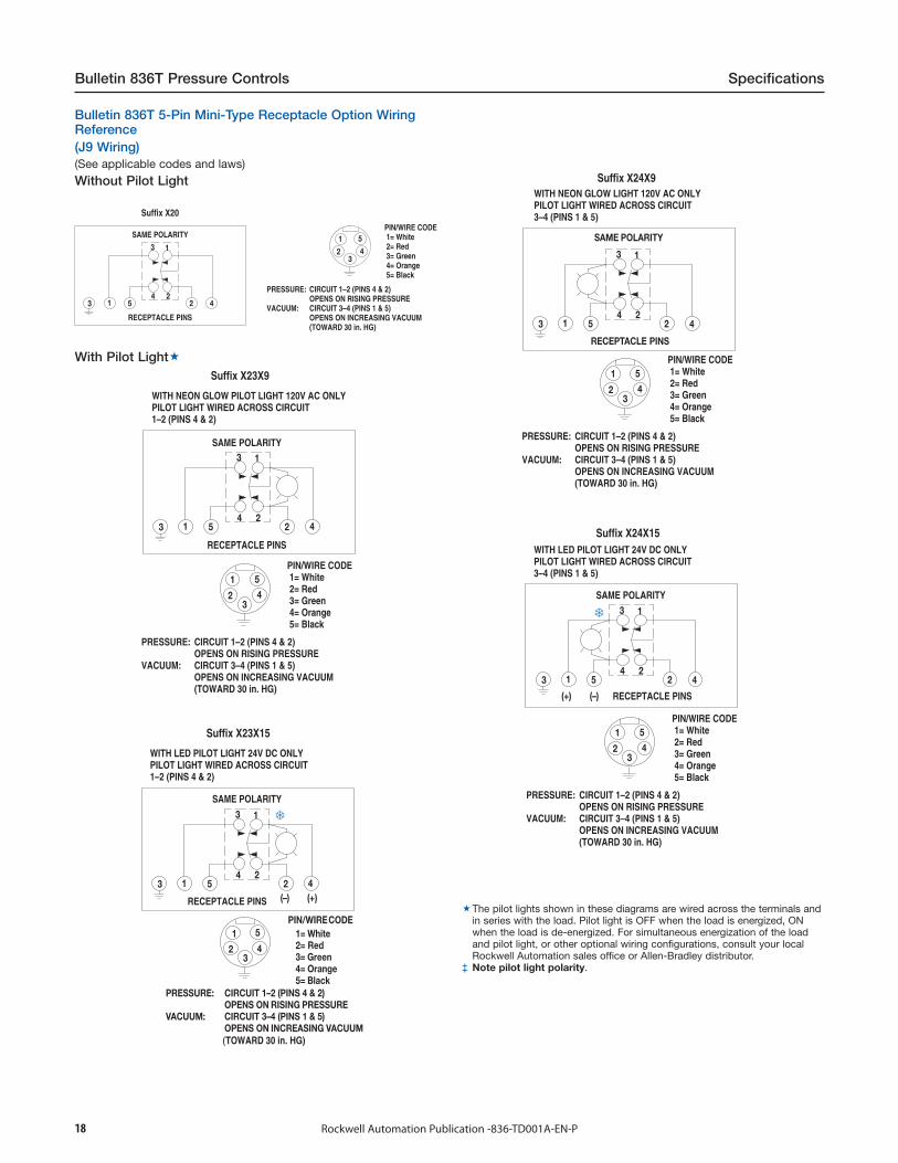
Bulletin 836T 5-Pin Mini-Type Receptacle Option WiringReference(J9 Wiring)(See applicable codes and laws)
Without Pilot Light
PIN/WIRE CODE 1= White 2= Red 3= Green 4= Orange 5= Black
PRESSURE: CIRCUIT 1–2 (PINS 4 & 2) OPENS ON RISING PRESSUREVACUUM: CIRCUIT 3–4 (PINS 1 & 5) OPENS ON INCREASING VACUUM (TOWARD 30 in. HG)
Suffix X20
SAME POLARITY
RECEPTACLE PINS
With Pilot LightSuffix X23X9
WITH NEON GLOW PILOT LIGHT 120V AC ONLY PILOT LIGHT WIRED ACROSS CIRCUIT1–2 (PINS 4 & 2)
SAME POLARITY
RECEPTACLE PINS
PIN/WIRE CODE 1= White 2= Red 3= Green 4= Orange 5= Black
PRESSURE: CIRCUIT 1–2 (PINS 4 & 2) OPENS ON RISING PRESSUREVACUUM: CIRCUIT 3–4 (PINS 1 & 5) OPENS ON INCREASING VACUUM (TOWARD 30 in. HG)
Suffix X23X15
WITH LED PILOT LIGHT 24V DC ONLY PILOT LIGHT WIRED ACROSS CIRCUIT1–2 (PINS 4 & 2)
SAME POLARITY
RECEPTACLE PINS
Suffix X24X9WITH NEON GLOW LIGHT 120V AC ONLY PILOT LIGHT WIRED ACROSS CIRCUIT3–4 (PINS 1 & 5)
PIN/WIRE CODE 1= White 2= Red 3= Green 4= Orange 5= Black
PRESSURE: CIRCUIT 1–2 (PINS 4 & 2) OPENS ON RISING PRESSUREVACUUM: CIRCUIT 3–4 (PINS 1 & 5) OPENS ON INCREASING VACUUM (TOWARD 30 in. HG)
SAME POLARITY
RECEPTACLE PINS
WITH LED PILOT LIGHT 24V DC ONLY PILOT LIGHT WIRED ACROSS CIRCUIT3–4 (PINS 1 & 5)
Suffix X24X15
PIN/WIRE CODE 1= White 2= Red 3= Green 4= Orange 5= Black
PRESSURE: CIRCUIT 1–2 (PINS 4 & 2) OPENS ON RISING PRESSUREVACUUM: CIRCUIT 3–4 (PINS 1 & 5) OPENS ON INCREASING VACUUM (TOWARD 30 in. HG)
The pilot lights shown in these diagrams are wired across the terminals andin series with the load. Pilot light is OFF when the load is energized, ONwhen the load is de-energized. For simultaneous energization of the loadand pilot light, or other optional wiring configurations, consult your localRockwell Automation sales office or Allen-Bradley distributor.
‡ Note pilot light polarity.

19Rockwell Automation Publication -836-TD001A-EN-P
Specifications Bulletin 836T Pressure Controls
Bulletin 836T 5-Pin Mini-Type Receptacle Option WiringReference(See applicable codes and laws)
With Pilot LightSuffix X81X9
WITH NEON GLOW LIGHT 120V AC ONLY RATED 600V 8 AMPS
PIN/WIRE CODE 1= White 2= Red 3= Green 4= Orange 5= Black
PRESSURE: CIRCUIT 1–2 (PINS 5 & 4) OPENS ON RISING PRESSUREVACUUM: CIRCUIT 3–4 (PINS 5 & 1) OPENS ON INCREASING VACUUM (TOWARD 30 in. HG)
SAME POLARITY
RECEPTACLE PINS
Suffix X81X15
WITH LED PILOT LIGHT 24V DC ONLY RATED 600V 8 AMPS
SAME POLARITY
RECEPTACLE PINS
PIN/WIRE CODE 1= White 2= Red 3= Green 4= Orange 5= Black
PRESSURE: CIRCUIT 1–2 (PINS 5 & 4) OPENS ON RISING PRESSUREVACUUM: CIRCUIT 3–4 (PINS 5 & 1) OPENS ON INCREASING VACUUM (TOWARD 30 in. HG)
Note: Bulletin 836T Suffix “X81” Wiring — load and pilot lightsimultaneously energize when contacts displace (contact terminals 3and 4 close) at a predetermined pressure setting.
20 Rockwell Automation Publication -836-TD001A-EN-P
Bulletin 836T Pressure Controls Specifications
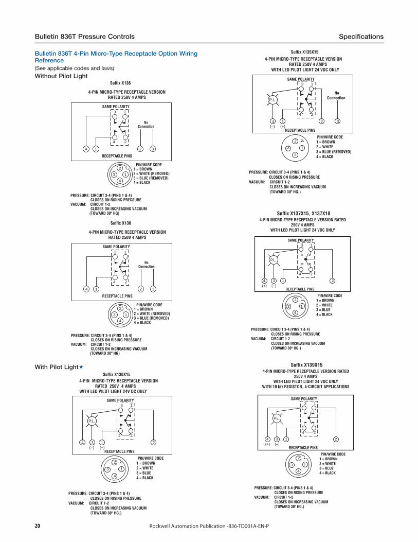
Bulletin 836T 4-Pin Micro-Type Receptacle Option WiringReference(See applicable codes and laws)
Without Pilot Light
RECEPTACLE PINS
SAME POLARITY3 1
4 2
4-PIN MICRO-TYPE RECEPTACLE VERSIONRATED 250V 4 AMPS
1 = BROWN2 = WHITE (REMOVED)3 = BLUE (REMOVED)4 = BLACK
PIN/WIRE CODE
PRESSURE: CIRCUIT 3-4 (PINS 1 & 4) CLOSES ON RISING PRESSUREVACUUM: CIRCUIT 1-2 CLOSES ON INCREASING VACUUM (TOWARD 30" HG)
1
2
3
4
4 1 32
NoConnection
Suffix X136
With Pilot Light
4-PIN MICRO-TYPE RECEPTACLE VERSIONRATED 250V 4 AMPS
PRESSURE: CIRCUIT 3-4 (PINS 1 & 4) CLOSES ON RISING PRESSUREVACUUM: CIRCUIT 1-2 CLOSES ON INCREASING VACUUM (TOWARD 30" HG.)
PIN/WIRE CODE1 = BROWN2 = WHITE3 = BLUE4 = BLACK
RECEPTACLE PINS
SAME POLARITY3 1
4 2
234 1
3
2
4
1
P.L.
(+)(–)
_ _ _ __ _
_ _
_ _
_
_ _ _ _
_ _
_ _
_ _
_
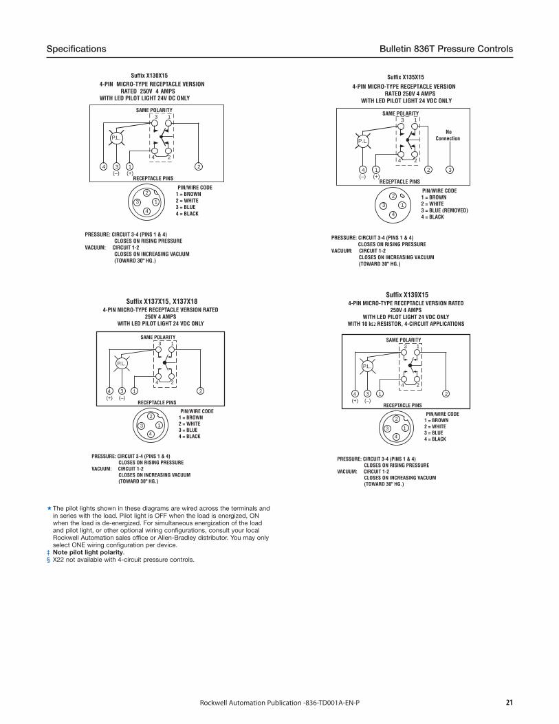
Suffix X130X15
WITH LED PILOT LIGHT 24V DC ONLY
4-PIN MICRO-TYPE RECEPTACLE VERSIONRATED 250V 4 AMPS
WITH LED PILOT LIGHT 24 VDC ONLY
PRESSURE: CIRCUIT 3-4 (PINS 1 & 4) CLOSES ON RISING PRESSUREVACUUM: CIRCUIT 1-2
CLOSES ON INCREASING VACUUM (TOWARD 30" HG.)
PIN/WIRE CODE1 = BROWN2 = WHITE3 = BLUE (REMOVED)4 = BLACK
RECEPTACLE PINS
SAME POLARITY3 1
4 2
24 1
3
2
4
1
P.L.
(+)(–)
_ _ _ __ _
_ _
_ _
_
_ _ _ _
_ _
_ _
_ _
_
3
NoConnection
Suffix X135X15
PRESSURE: CIRCUIT 3-4 (PINS 1 & 4) CLOSES ON RISING PRESSUREVACUUM: CIRCUIT 1-2 CLOSES ON INCREASING VACUUM (TOWARD 30" HG.)
PIN/WIRE CODE1 = BROWN2 = WHITE3 = BLUE4 = BLACK
RECEPTACLE PINS
SAME POLARITY3 1
4 2
234 1
3
2
4
1
(+) (–)
4-PIN MICRO-TYPE RECEPTACLE VERSION RATED 250V 4 AMPS
WITH LED PILOT LIGHT 24 VDC ONLY
P.L.
Suffix X137X15, X137X18
PRESSURE: CIRCUIT 3-4 (PINS 1 & 4) CLOSES ON RISING PRESSUREVACUUM: CIRCUIT 1-2 CLOSES ON INCREASING VACUUM (TOWARD 30" HG.)
PIN/WIRE CODE1 = BROWN2 = WHITE3 = BLUE4 = BLACK
RECEPTACLE PINS
SAME POLARITY3 1
4 2
234 1
3
2
4
1
(+) (–)
4-PIN MICRO-TYPE RECEPTACLE VERSION RATED 250V 4 AMPS
WITH LED PILOT LIGHT 24 VDC ONLYWITH 10 kΩ RESISTOR, 4-CIRCUIT APPLICATIONS
P.L.
Suffix X139X15
21Rockwell Automation Publication -836-TD001A-EN-P
Specifications Bulletin 836T Pressure Controls
4-PIN MICRO-TYPE RECEPTACLE VERSIONRATED 250V 4 AMPS
PRESSURE: CIRCUIT 3-4 (PINS 1 & 4) CLOSES ON RISING PRESSUREVACUUM: CIRCUIT 1-2 CLOSES ON INCREASING VACUUM (TOWARD 30" HG.)
PIN/WIRE CODE1 = BROWN2 = WHITE3 = BLUE4 = BLACK
RECEPTACLE PINS
SAME POLARITY3 1
4 2
234 1
3
2
4
1
P.L.
(+)(–)
_ _ _ __ _
_ _
_ _
_
_ _ _ _
_ _
_ _
_ _
_
Suffix X130X15
WITH LED PILOT LIGHT 24V DC ONLY
4-PIN MICRO-TYPE RECEPTACLE VERSIONRATED 250V 4 AMPS
WITH LED PILOT LIGHT 24 VDC ONLY
PRESSURE: CIRCUIT 3-4 (PINS 1 & 4) CLOSES ON RISING PRESSUREVACUUM: CIRCUIT 1-2
CLOSES ON INCREASING VACUUM (TOWARD 30" HG.)
PIN/WIRE CODE1 = BROWN2 = WHITE3 = BLUE (REMOVED)4 = BLACK
RECEPTACLE PINS
SAME POLARITY3 1
4 2
24 1
3
2
4
1
P.L.
(+)(–)
_ _ _ __ _
_ _
_ _
_
_ _ _ _
_ _
_ _
_ _
_
3
NoConnection
Suffix X135X15
PRESSURE: CIRCUIT 3-4 (PINS 1 & 4) CLOSES ON RISING PRESSUREVACUUM: CIRCUIT 1-2 CLOSES ON INCREASING VACUUM (TOWARD 30" HG.)
PIN/WIRE CODE1 = BROWN2 = WHITE3 = BLUE4 = BLACK
RECEPTACLE PINS
SAME POLARITY3 1
4 2
234 1
3
2
4
1
(+) (–)
4-PIN MICRO-TYPE RECEPTACLE VERSION RATED 250V 4 AMPS
WITH LED PILOT LIGHT 24 VDC ONLY
P.L.
Suffix X137X15, X137X18
PRESSURE: CIRCUIT 3-4 (PINS 1 & 4) CLOSES ON RISING PRESSUREVACUUM: CIRCUIT 1-2 CLOSES ON INCREASING VACUUM (TOWARD 30" HG.)
PIN/WIRE CODE1 = BROWN2 = WHITE3 = BLUE4 = BLACK
RECEPTACLE PINS
SAME POLARITY3 1
4 2
234 1
3
2
4
1
(+) (–)
4-PIN MICRO-TYPE RECEPTACLE VERSION RATED 250V 4 AMPS
WITH LED PILOT LIGHT 24 VDC ONLYWITH 10 kΩ RESISTOR, 4-CIRCUIT APPLICATIONS
P.L.
Suffix X139X15
The pilot lights shown in these diagrams are wired across the terminals andin series with the load. Pilot light is OFF when the load is energized, ONwhen the load is de-energized. For simultaneous energization of the loadand pilot light, or other optional wiring configurations, consult your localRockwell Automation sales office or Allen-Bradley distributor. You may onlyselect ONE wiring configuration per device.
‡ Note pilot light polarity.§ X22 not available with 4-circuit pressure controls.

22 Rockwell Automation Publication -836-TD001A-EN-P
Bulletin 836T Pressure Controls Specifications
Bulletin 836T 5-Pin Micro-Type Receptacle Option WiringReference(See applicable codes and laws)
With Pilot Light
5-PIN MICRO-TYPE RECEPTACLE VERSION RATED 300V 3 AMPS
WITH LED PILOT LIGHT 24VDC ONLY
PRESSURE: CIRCUIT 3-4 (PINS 1&5) CLOSES ON RISING PRESSUREVACUUM: CIRCUIT 1-2 CLOSES ON INCREASING VACUUM (TOWARD 30" HG.)
PIN/WIRE CODE1 = RED-WHT. TR.2 = RED (REMOVED)3 = GREEN4 = RED-YEL. TR.5 = RED-BLK. TR.
RECEPTACLE PINS
SAME POLARITY3 1
4 2
213
P.L.
4 5
No Connection
32 4
1 5
OBSERVE PILOTLIGHT POLARITY
(+) (-)
Suffix X145X9 (120V AC), X145X15 (24V DC), X145X18 (24V DC)
RECEPTACLE PINS
SAME POLARITY3 1
4 2
5-PIN MICRO-TYPE RECEPTACLE VERSIONRATED 300V 3 AMPS
WITH NEON GLOW PILOT LIGHT 120VAC ONLY
1 = RED-WHITE TR.2 = RED3 = GREEN4 = RED-YEL. TR.5 = RED-BLACK TR.
PIN/WIRE CODE
PRESSURE: CIRCUIT 1-2 (PINS 5 & 4) OPENS ON RISING PRESSUREVACUUM: CIRCUIT 3-4 (PINS 5 & 1) OPENS ON INCREASING VACUUM (TOWARD 30" HG.)
3 5 1 4 2
P.L.
32
1 5
4
Suffix X181X9, X181X15, X181X18
The pilot lights shown in these diagrams are wired across the terminals andin series with the load. Pilot light is OFF when the load is energized, ONwhen the load is de-energized. For simultaneous energization of the loadand pilot light, or other optional wiring configurations, consult your localRockwell Automation sales office or Allen-Bradley distributor. You may onlyselect ONE wiring configuration per device.
‡ Note pilot light polarity.§ X22 not available with 4-circuit pressure controls.
23Rockwell Automation Publication -836-TD001A-EN-P
Specifications Bulletin 836T Pressure Controls
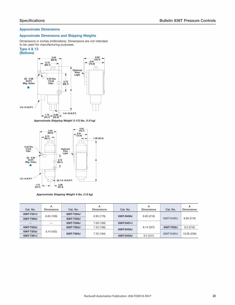
Approximate Dimensions
Approximate Dimensions and Shipping Weights
Dimensions in inches (millimeters). Dimensions are not intendedto be used for manufacturing purposes.
Type 4 & 13(Bellows)
3.50(88.9)
1.72(43.7)
2.72(69.1)
2.72(69.1)
A
OptionalPilotLight
(2) 0.28(0.67)
Mtg. Holes
0.53 Dia.(13.5)Ctbr.
1/2-14 N.P.T.
0.88(22.3)
1/4-18 N.P.T.
3.02(76.7)
2.91(73.9)
**
Approximate Shipping Weight 3-1/2 lbs. (1.6 kg)
3.50(88.9)
2.72(69.1)
2.72(69.1)
(2) 0.28(0.67)
Mtg. Holes
0.53 Dia.(13.5)Ctbr.
1/2-14 N.P.T
1.72(43.7)
0.88(22.3)
(2) 1/4-18 N.P.T.
3.02(76.7)
2.91(73.9)
1.28 (32.5)
A
OptionalPilotLight
**
Approximate Shipping Weight 4 lbs. (1.8 kg)
Cat. No.A
Dimensions Cat. No.A
Dimensions Cat. No.A
Dimensions Cat. No.A
Dimensions
836T-T251J6.65 (169)
836T-T254J6.95 (176) 836T-D450J 8.60 (218)
836T-D460J 8.60 (218)836T-T260J 836T-T255J
— — 836T-T256J 7.09 (180) 836T-D451J
8.14 (207)836T-T252J
6.41(163)
836T-T262J 7.33 (186)836T-D452J
836T-T252J 8.5 (216)
836T-T253J836T-T263J 7.25 (184) 836T-D463J 10.06 (256)
836T-T261J 836T-D453J 9.5 (241)

24 Rockwell Automation Publication -836-TD001A-EN-P
Bulletin 836T Pressure Controls Specifications
Type 4 & 13(Piston)Type 4 & 13 and 7 & 9Bellows and Piston Type(Does not include Dual Bellows Devices)
3.50(88.9)
7.17(182)
OptionalPilotLight
Drain1/8-27 N.P.T.
3.02(76.7)
2.91(73.8)
6.38(162.1)
0.50(12.7)
0.50(12.7)
0.88(22.4)
2.72(69.1)
(2) 0.28(0.67)
Mtg. Holes 0.53 Dia.(13.5)Ctbr.
1/2-14 N.P.T.
1.72(43.7)
0.88(22.3)
3/8-18 N.P.T.
5.55(141)
8.63(219.2)
1.38(35.1)
0.84(21.3)Typ.
4.69(119.1)
2.69(68.3)
1.69(42.9)
3/8"-18 N.P.T.1/8"-27 N.P.T.Oil Drain Connection
Plugged WhenNot in Use
3/4"-14 N.P.T.Conduit Connection
0.44 Dia.(11.2)
Mtg. HolesQty. 2
0.69(17.5)
**
Approximate Shipping Weight 4.5 lbs. (2.0 kg)Approximate Shipping Weight 10 lbs. (4.5 kg)
(2) mounting screws are required: 3/16 x 20 x 2 in. Counterbore depth is 1-1/8 in. Overall depth of mtg hole (front to back) is 2-1/4 in.
25Rockwell Automation Publication -836-TD001A-EN-P
Specifications Bulletin 808 Speed Switches
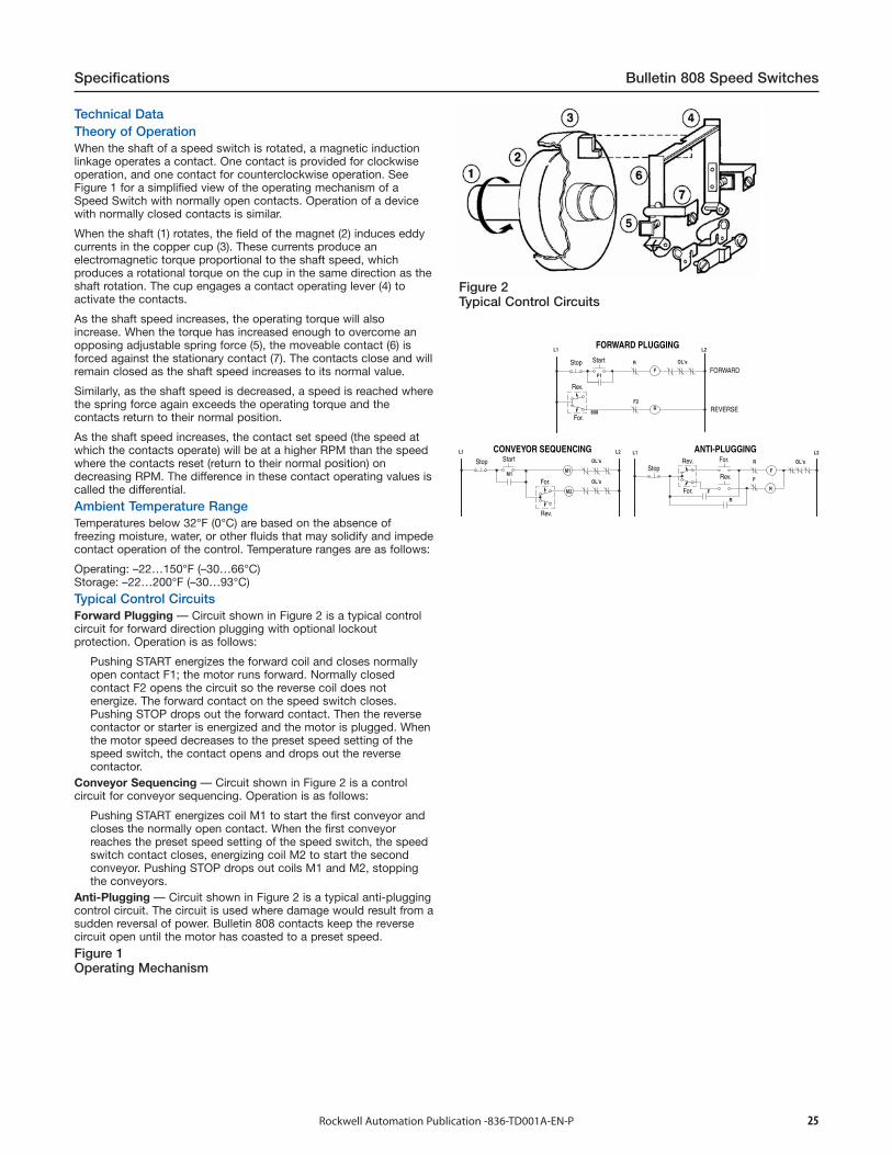
Technical DataTheory of OperationWhen the shaft of a speed switch is rotated, a magnetic inductionlinkage operates a contact. One contact is provided for clockwiseoperation, and one contact for counterclockwise operation. SeeFigure 1 for a simplified view of the operating mechanism of aSpeed Switch with normally open contacts. Operation of a devicewith normally closed contacts is similar.
When the shaft (1) rotates, the field of the magnet (2) induces eddycurrents in the copper cup (3). These currents produce anelectromagnetic torque proportional to the shaft speed, whichproduces a rotational torque on the cup in the same direction as theshaft rotation. The cup engages a contact operating lever (4) toactivate the contacts.
As the shaft speed increases, the operating torque will alsoincrease. When the torque has increased enough to overcome anopposing adjustable spring force (5), the moveable contact (6) isforced against the stationary contact (7). The contacts close and willremain closed as the shaft speed increases to its normal value.
Similarly, as the shaft speed is decreased, a speed is reached wherethe spring force again exceeds the operating torque and thecontacts return to their normal position.
As the shaft speed increases, the contact set speed (the speed atwhich the contacts operate) will be at a higher RPM than the speedwhere the contacts reset (return to their normal position) ondecreasing RPM. The difference in these contact operating values iscalled the differential.
Ambient Temperature RangeTemperatures below 32°F (0°C) are based on the absence offreezing moisture, water, or other fluids that may solidify and impedecontact operation of the control. Temperature ranges are as follows:
Operating: –22…150°F (–30…66°C)Storage: –22…200°F (–30…93°C)
Typical Control CircuitsForward Plugging — Circuit shown in Figure 2 is a typical controlcircuit for forward direction plugging with optional lockoutprotection. Operation is as follows:
Pushing START energizes the forward coil and closes normallyopen contact F1; the motor runs forward. Normally closedcontact F2 opens the circuit so the reverse coil does notenergize. The forward contact on the speed switch closes.Pushing STOP drops out the forward contact. Then the reversecontactor or starter is energized and the motor is plugged. Whenthe motor speed decreases to the preset speed setting of thespeed switch, the contact opens and drops out the reversecontactor.
Conveyor Sequencing — Circuit shown in Figure 2 is a controlcircuit for conveyor sequencing. Operation is as follows:
Pushing START energizes coil M1 to start the first conveyor andcloses the normally open contact. When the first conveyorreaches the preset speed setting of the speed switch, the speedswitch contact closes, energizing coil M2 to start the secondconveyor. Pushing STOP drops out coils M1 and M2, stoppingthe conveyors.
Anti-Plugging — Circuit shown in Figure 2 is a typical anti-pluggingcontrol circuit. The circuit is used where damage would result from asudden reversal of power. Bulletin 808 contacts keep the reversecircuit open until the motor has coasted to a preset speed.
Figure 1Operating Mechanism
Figure 2Typical Control Circuits
FORWARD PLUGGING
ANTI-PLUGGINGCONVEYOR SEQUENCING
FORWARD
REVERSE
Stop
StopStop
Start
Start
Rev.
Rev.
Rev.
Rev.
For.
For.For.
For.
26 Rockwell Automation Publication -836-TD001A-EN-P
Bulletin 808 Speed Switches Specifications
Normally Open Contacts Normally Closed Contacts
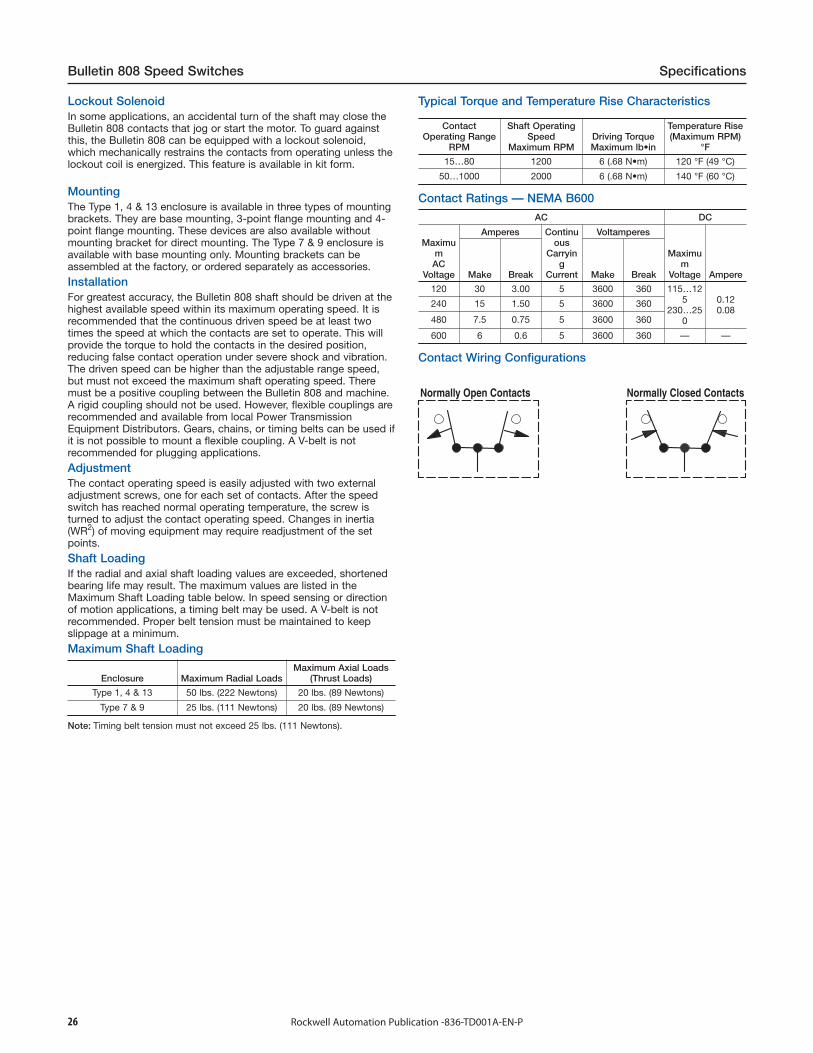
Lockout SolenoidIn some applications, an accidental turn of the shaft may close theBulletin 808 contacts that jog or start the motor. To guard againstthis, the Bulletin 808 can be equipped with a lockout solenoid,which mechanically restrains the contacts from operating unless thelockout coil is energized. This feature is available in kit form.
MountingThe Type 1, 4 & 13 enclosure is available in three types of mountingbrackets. They are base mounting, 3-point flange mounting and 4-point flange mounting. These devices are also available withoutmounting bracket for direct mounting. The Type 7 & 9 enclosure isavailable with base mounting only. Mounting brackets can beassembled at the factory, or ordered separately as accessories.
InstallationFor greatest accuracy, the Bulletin 808 shaft should be driven at thehighest available speed within its maximum operating speed. It isrecommended that the continuous driven speed be at least twotimes the speed at which the contacts are set to operate. This willprovide the torque to hold the contacts in the desired position,reducing false contact operation under severe shock and vibration.The driven speed can be higher than the adjustable range speed,but must not exceed the maximum shaft operating speed. Theremust be a positive coupling between the Bulletin 808 and machine.A rigid coupling should not be used. However, flexible couplings arerecommended and available from local Power TransmissionEquipment Distributors. Gears, chains, or timing belts can be used ifit is not possible to mount a flexible coupling. A V-belt is notrecommended for plugging applications.
AdjustmentThe contact operating speed is easily adjusted with two externaladjustment screws, one for each set of contacts. After the speedswitch has reached normal operating temperature, the screw isturned to adjust the contact operating speed. Changes in inertia(WR2) of moving equipment may require readjustment of the setpoints.
Shaft LoadingIf the radial and axial shaft loading values are exceeded, shortenedbearing life may result. The maximum values are listed in theMaximum Shaft Loading table below. In speed sensing or directionof motion applications, a timing belt may be used. A V-belt is notrecommended. Proper belt tension must be maintained to keepslippage at a minimum.
Maximum Shaft Loading
Enclosure Maximum Radial LoadsMaximum Axial Loads
(Thrust Loads)
Type 1, 4 & 13 50 lbs. (222 Newtons) 20 lbs. (89 Newtons)
Type 7 & 9 25 lbs. (111 Newtons) 20 lbs. (89 Newtons)
Note: Timing belt tension must not exceed 25 lbs. (111 Newtons).
Typical Torque and Temperature Rise Characteristics
ContactOperating Range
RPM
Shaft OperatingSpeed
Maximum RPMDriving TorqueMaximum lb•in
Temperature Rise(Maximum RPM)
°F
15…80 1200 6 (.68 N•m) 120 °F (49 °C)
50…1000 2000 6 (.68 N•m) 140 °F (60 °C)
Contact Ratings — NEMA B600
AC DC
MaximumAC
Voltage
Amperes Continuous
Carrying
Current
Voltamperes
Maximum
Voltage AmpereMake Break Make Break
120 30 3.00 5 3600 360 115…125
230…250
0.120.08
240 15 1.50 5 3600 360
480 7.5 0.75 5 3600 360
600 6 0.6 5 3600 360 — —
Contact Wiring Configurations
27Rockwell Automation Publication -836-TD001A-EN-P
Specifications Bulletin 808 Speed Switches
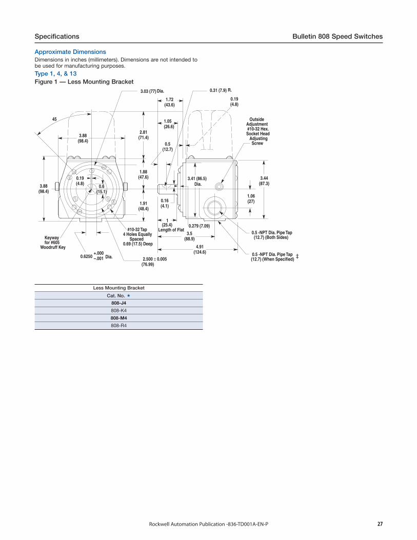
Approximate DimensionsDimensions in inches (millimeters). Dimensions are not intended tobe used for manufacturing purposes.
Type 1, 4, & 13Figure 1 — Less Mounting Bracket
Dia. R.
OutsideAdjustment #10-32 Hex.Socket Head Adjusting Screw
Dia.
Keyway for #605Woodruff Key
Dia.
#10-32 Tap4 Holes Equally Spaced0.69 (17.5) Deep
Length of Flat 0.5 -NPT Dia. Pipe Tap (12.7) (Both Sides)
0.5 -NPT Dia. Pipe Tap (12.7) (When Specified)
Less Mounting Bracket
Cat. No.
808-J4
808-K4
808-M4
808-R4
28 Rockwell Automation Publication -836-TD001A-EN-P
Bulletin 808 Speed Switcheses Specifications
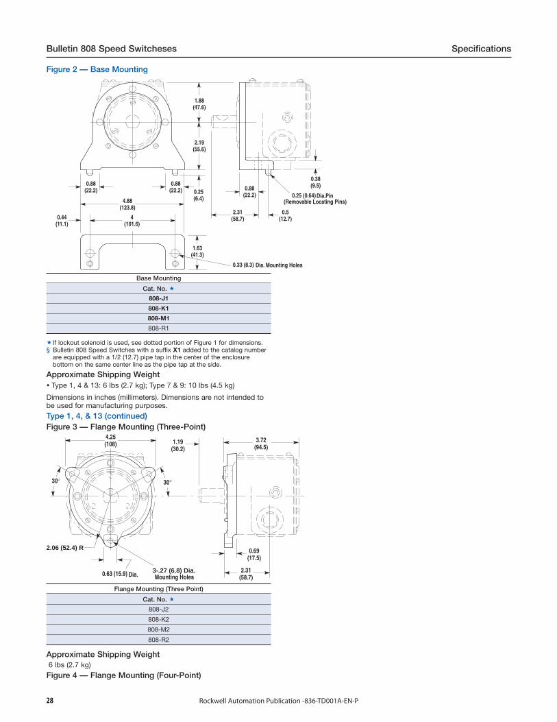
Figure 2 — Base Mounting
Dia. Mounting Holes
Dia.Pin(Removable Locating Pins)
Base Mounting
Cat. No.
808-J1
808-K1
808-M1
808-R1
If lockout solenoid is used, see dotted portion of Figure 1 for dimensions.§ Bulletin 808 Speed Switches with a suffix X1 added to the catalog number
are equipped with a 1/2 (12.7) pipe tap in the center of the enclosurebottom on the same center line as the pipe tap at the side.
Approximate Shipping Weight Type 1, 4 & 13: 6 lbs (2.7 kg); Type 7 & 9: 10 lbs (4.5 kg)
Dimensions in inches (millimeters). Dimensions are not intended tobe used for manufacturing purposes.
Type 1, 4, & 13 (continued)Figure 3 — Flange Mounting (Three-Point)
2.06 (52.4) R
3-.27 (6.8) Dia.Dia. Mounting Holes
Flange Mounting (Three Point)
Cat. No.
808-J2
808-K2
808-M2
808-R2
Approximate Shipping Weight6 lbs (2.7 kg)
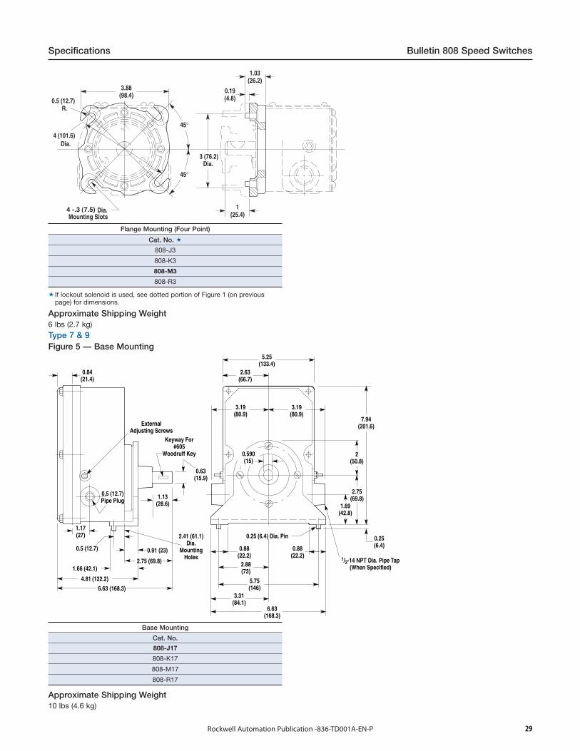
Figure 4 — Flange Mounting (Four-Point)
29Rockwell Automation Publication -836-TD001A-EN-P
Specifications Bulletin 808 Speed Switches
Dia.
Dia.
R.
Dia.Mounting Slots
Flange Mounting (Four Point)
Cat. No.
808-J3
808-K3
808-M3
808-R3
If lockout solenoid is used, see dotted portion of Figure 1 (on previouspage) for dimensions.
Approximate Shipping Weight6 lbs (2.7 kg)
Type 7 & 9Figure 5 — Base Mounting
Base Mounting
Cat. No.
808-J17
808-K17
808-M17
808-R17
Approximate Shipping Weight10 lbs (4.6 kg)
30 Rockwell Automation Publication -836-TD001A-EN-P
Bulletin 837 Temperature Controls Specifications
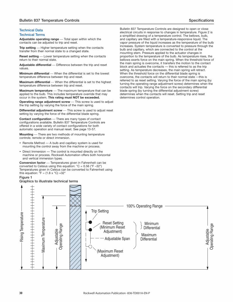
Technical DataTechnical TermsAdjustable operating range ⎯ Total span within which thecontacts can be adjusted to trip and reset.
Trip setting ⎯ Higher temperature setting when the contactstransfer from their normal state to a changed state.
Reset setting ⎯ Lower temperature setting when the contactsreturn to their normal state.
Adjustable differential ⎯ Difference between the trip and resetvalues.
Minimum differential ⎯ When the differential is set to the lowesttemperature difference between trip and reset.
Maximum differential ⎯ When the differential is set to the highesttemperature difference between trip and reset.
Maximum temperature ⎯ The maximum temperature that can beapplied to the bulb. This includes temperature override that mayoccur in the system. This rating must NOT be exceeded.Operating range adjustment screw ⎯ This screw is used to adjustthe trip setting by varying the force of the main spring.
Differential adjustment screw ⎯ This screw is used to adjust resetsetting by varying the force of the differential blade spring.
Contact configuration ⎯ There are many types of contactconfigurations available. Bulletin 837 Temperature Controls areoffered in a wide variety of contact configurations for bothautomatic operation and manual reset. See page 13-57.
Mounting ⎯ There are two methods of mounting temperaturecontrols: remote or direct immersion.
Remote Method — A bulb and capillary system is used formounting the control away from the machine or process.
Direct Immersion — The control is mounted directly on themachine or process. Rockwell Automation offers both horizontaland vertical immersion types.
Conversion factor ⎯ Temperatures given in Fahrenheit can beconverted to Celsius using this equation: °C = 0.56 (°F –32°)Temperatures given in Celsius can be converted to Fahrenheit usingthis equation: °F = (1.8 x °C) +32°
Figure 1Graphics to illustrate technical terms
Ris
ing
Tem
pera
ture
100% Operating Range
Max
imum
Tem
pera
ture
A
djus
tabl
eO
pera
ting
Ran
ge
A
djus
tabl
eO
pera
ting
Ran
geTrip Setting
Reset Setting(Minimum Reset Adjustment)
Adjustable Span
(Maximum Reset Adjustment)
Minimum Differential
MaximumDifferential
Bulletin 837 Temperature Controls are designed to open or closeelectrical circuits in response to changes in temperature. Figure 2 isa simplified drawing of a temperature control. The bellows, bulb,and capillary are filled with a temperature-responsive liquid. Thevapor pressure of the liquid increases as the temperature of the bulbincreases. System temperature is converted to pressure through thebulb and capillary, which are connected to the control at themounting stem. Pressure applied to the actuator changes inproportion to the temperature of the bulb. As temperature rises, thebellows exerts force on the main spring. When the threshold force ofthe main spring is overcome, it transfers the motion to the contactblock and actuates the contacts — this is referred to as the tripsetting. As temperature decreases, the main spring will retract.When the threshold force on the differential blade spring isovercome, the contacts will return to their normal state —this isreferred to as reset setting. Varying the force of the main spring (byturning the operating range adjustment screw) determines when thecontacts will trip. Varying the force on the secondary differentialblade spring (by turning the differential adjustment screw)determines when the contacts will reset. Setting trip and resetdetermines control operation.

31Rockwell Automation Publication -836-TD001A-EN-P
Specifications Bulletin 837 Temperature Controls
Contact Block
Differential Blade Spring
Main Spring
Bellows Actuator
Mounting Stem
Capillary
Bulb
Applications for ControlTemperature controls can be used to either control or monitor amachine or process. Figure 3 shows a typical control application.Here, temperature is controlled within predetermined high and lowvalues. Figure 4 shows a typical monitoring application. Here,temperature is monitored between a high and low value, signalingwhen a preset limit has been exceeded.
Figure 3Typical control application
Time
°F
NormalState
ChangedState
NormalState
ChangedState
Trip
Differential
Reset
OutputContacts
Figure 4Typical monitoring application
Time
°F
NormalState
ChangedState
NormalState
ChangedState
Trip
Differential
Reset
OutputContacts
Control SettingsAllen-Bradley Temperature Controls are designed for ease of settingto help minimize installation time. Standard controls shipped fromthe factory are set at the maximum operating range and minimumdifferential. By following this simple two step process, the controlcan be set to the specific requirements for each application. SeeFigure 5.
Step 1 ⎯ Adjust trip settingThe trip setting is achieved by turning the operating rangeadjustment screw. Turn the screw counterclockwise to lower the tripsetting or clockwise to raise the trip setting. The approximate tripsetting is shown on the indicating scale.
Step 2 — Adjust reset settingThe reset setting is achieved by turning the differential adjustmentscrew counterclockwise to increase the differential or clockwise todecrease the differential.
Theory of OperationFigure 2Basic mechanical structure
Finger-Safe Contact Block ShieldMeets UL873, IEC 529 / IP2X & CSA
Self Lifting Pressure Plate Terminals
Indicating Scale °F(Approximate Trip Setting)
Operating RangeAdjustment Screw
Indicating Scale °C(Approximate Trip Setting)
Differential Adjustment Screw
Figure 5Trip and reset adjustment

32 Rockwell Automation Publication -836-TD001A-EN-P
Bulletin 837 Temperature Controls Specifications
Thermostat WellsThermostat wells are basically sealed tubes on one end with threadson the other that allow mounting directly into a system. Thermostatwells protect the bulbs and allow installing or removing controls forcalibration without discharging or draining an entire system. Thebulb of a temperature control is inserted into the well which issecured with a locking nut for standard bulb and capillary devices.Bulbs for armored capillary devices are secured with a sleeve nutand set screw to prevent the armor from sliding back exposing thecapillary. The bulbs of direct immersion devices are secured with aset screw which is also used to mount the control. Thermostat wellsare rated for 1000 psi at 600 °F. Thermostat wells used whenmounting direct horizontal immersion controls will allow mountingthe control in a confined space. These devices otherwise require an11 in. swing diameter to secure the bulb into the system. See page13-58.
Packing GlandsPacking glands are used when the application requires the bulb tobe located deeper into a process than would be possible with athermostat well. The glands provide a seal at any desired lengthalong a standard capillary device. The bulb must be supported toresist damage from flow or turbulence within the system. Thecapillary of armored capillary devices can only be sealed at thesmall exposed section of capillary located at the bulb. Packingglands are not intended to seal around the armor. They are designedto withstand sealing pressures up to 50 psi. The packing glandcannot be assembled into a thermostat well. See page 13-58.
Armored Capillary
Slotted Retaining Nut
Well
SetScrew
ArmorRetaining Nut
Thermostat Wells
Armored Capillary Packing Gland
Slotted Packing Washers
Standard Capillary Packing Gland
Packing Glands
Bulb and CapillariesCopper bulbs and capillaries are supplied for lower temperatureranges. Stainless steel is used for temperatures above 260 °F.Stainless steel is also available on lower ranges for more corrosiveapplications. Capillary lengths of 3, 6, 12, 20, and 30 feet areavailable for all styles of temperature control devices.
ArmorBronze or stainless steel armor is available for added protection ofthe capillary. See Modifications on page 13-57 for orderinginstructions.
Capillary Bending RadiusCopper and Stainless Steel ⎯0.5 in. (12.7 mm) minimumwith Bronze and Stainless Steel Armor ⎯2 in. (50.8 mm) minimum
Direct ImmersionHorizontal and vertical immersion devices are used when thecontrols are required to be mounted directly on the machine or in aprocess.
Standard ContactContact OperationContact blocks are single-pole, double-throw and can be wired toopen or close on increasing or decreasing temperature.
Non-Inductive Ratings5 A, 240V3 A, 600V
Control Circuit RatingsAC — 125 VA, 24…600VDC — 57.5 VA, 115…230V
Standard Contact WiringConfiguration
Single-pole Double-throw
Repeat AccuracyThe vapor pressure technology used in Bulletin 837 controls tosense temperature provides an exceptionally long operating life.High quality chemicals and rigid control during manufacturingprovide a typical repeat accuracy of ±2 °F. Repeat accuracy isbased on percent of maximum range, evaluated from test data andcalculated using the formula per ICS 2-225 standards.
33Rockwell Automation Publication -836-TD001A-EN-P
Specifications Bulletin 837 Temperature Controls
A large number of unlisted catalog modifications and completedevices are available for specific and OEM applications. Specialcontrols and modification service is available to meet manyapplications unique to the OEM market.
Please consult your local Rockwell Automation sales office orAllen-Bradley distributor for assistance with specific modifiedcontrols and accessories.
Temperature Range
The temperature range for the mechanism at +32 °F (0 °C) or belowis based on the absence of freezing moisture, water or other fluidsthat may solidify and impede the operation of the control.Temperature ratings are as follows:
Operating: –22… +150 °F(–30…+66 °C)
Storage: –22…+200 °F(–30…+93 °C)
Factory-Set Temperature ControlsRockwell Automation will factory set temperature controls tocustomer-specified values if a Cat. No. 837-_C device is ordered.Unspecified temperature controls (cat. nos. without the "C" suffix)shipped from the factory are set at the maximum operating rangeand minimum differential. See Factory Options, page 13-59.
Application Note
When the ambient temperature surrounding the mechanism of thetemperature control approaches 30 °F (-1.1 °C) on either side of thesetting, a cross-ambient type control should be used. This willprotect against false temperature-sensing, as the bellows within themechanism may otherwise respond to changes in temperature. Cat.Nos. 837-A3 and 837-A4 bulb and capillary Types, all 837-V directvertical immersion, and all 837-H direct horizontal immersiondevices are cross-ambient.
When the bulb of cross-ambient bulb and capillary controls 837-A3and 837-A4 is to be mounted vertically, the capillary end of the bulbshould always be positioned higher than the termination end of thebulb.
When mounting the bulb horizontally, the word “TOP” stamped nearthe capillary of the bulb should be positioned upward toward the 12o' clock position. The capillary end of the bulb should never behigher than the termination end of the bulb. The direct verticalimmersion devices in the catalog series 837-V are conventionallymounted with the bulb downward, below the mechanism.
They must not be mounted with the bulb up. Since the horizontalimmersion device is not available in a Type 4 & 13 enclosure, thecorresponding vertical immersion device can be used. When thevertical immersion device is mounted horizontally, the word “TOP”stamped on the mounting thread “hex” should point upward towardthe 12 o' clock position.
The direct horizontal Immersion devices, in catalog series 837-Hshould always be mounted with the mechanism above the bulb. Theword “TOP” stamped on the mounting thread “hex” should pointupward toward the 12 o' clock position. Cat. No. 837-A2 is notcross-ambient and should not be used if the ambient temperatureapproaches or crosses over the set point as false temperature mayoccur.
Consult your local Rockwell Automation sales office or Allen-Bradleydistributor for assistance on special applications.NEMA does not rate contacts to switch low-voltage and current. Bulletin
837 Styles A, H and V Temperature Controls are supplied with silvercontacts. The devices are designed to deliver high force snap action to thecontacts. This provides exceptional contact fidelity at 24V DC I/O cardcurrent level entry when the integrity of the enclosure is maintained.
Special Controls
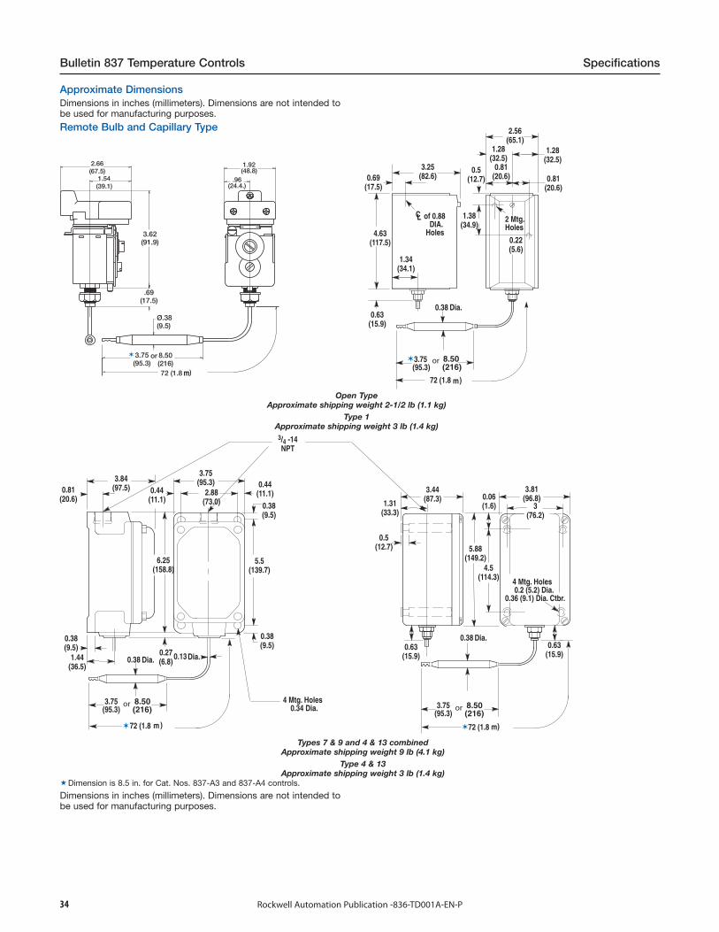
34 Rockwell Automation Publication -836-TD001A-EN-P
Bulletin 837 Temperature Controls Specifications
mm
of 0.88 DIA. Holes
2 Mtg.Holes
Open TypeApproximate shipping weight 2-1/2 lb (1.1 kg)
Type 1Approximate shipping weight 3 lb (1.4 kg)
m
4 Mtg. Holes 0.34 Dia.
4 Mtg. Holes 0.2 (5.2) Dia.0.36 (9.1) Dia. Ctbr.
m
Dia.
Dia. Dia.
Types 7 & 9 and 4 & 13 combinedApproximate shipping weight 9 lb (4.1 kg)
Type 4 & 13Approximate shipping weight 3 lb (1.4 kg)
Dimension is 8.5 in. for Cat. Nos. 837-A3 and 837-A4 controls.
Dimensions in inches (millimeters). Dimensions are not intended tobe used for manufacturing purposes.
Approximate DimensionsDimensions in inches (millimeters). Dimensions are not intended tobe used for manufacturing purposes.
Remote Bulb and Capillary Type
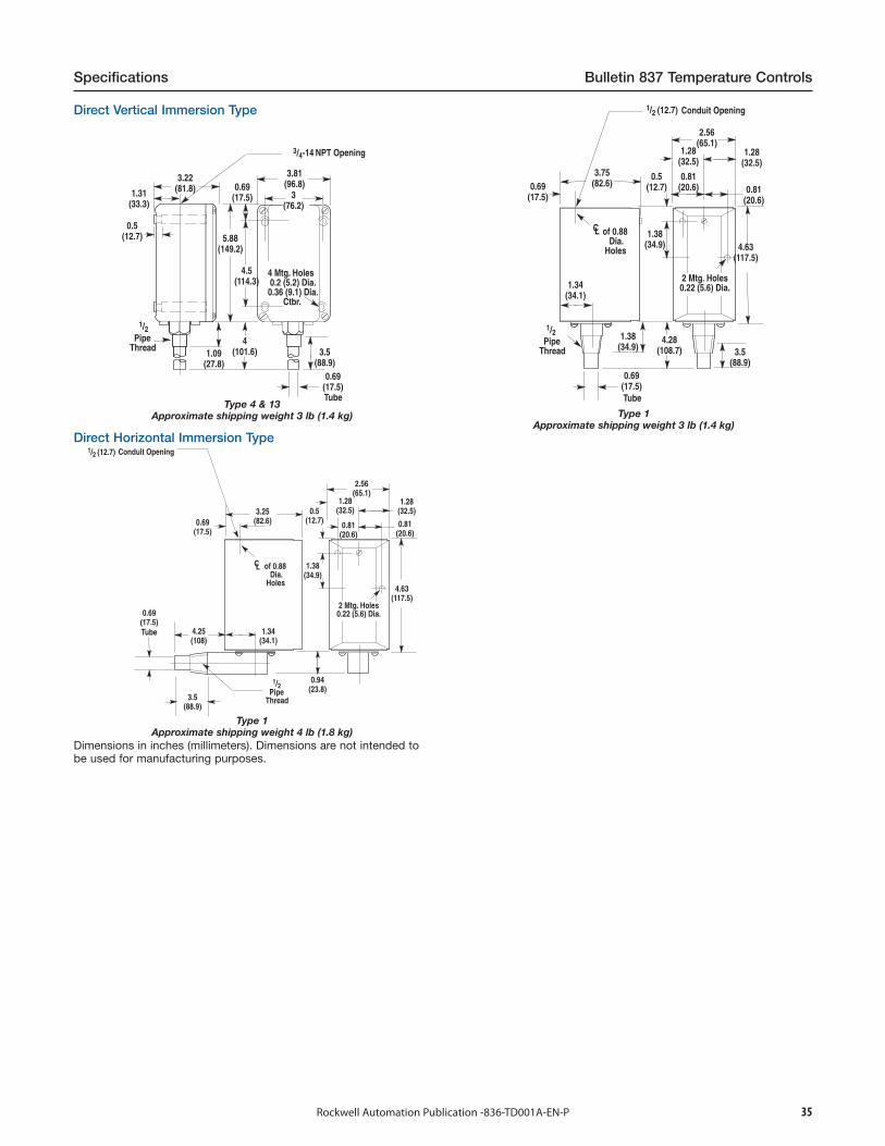
35Rockwell Automation Publication -836-TD001A-EN-P
Specifications Bulletin 837 Temperature Controls
4 Mtg. Holes 0.2 (5.2) Dia.0.36 (9.1) Dia. Ctbr.
PipeThread
Tube
NPT Opening
PipeThread
Conduit Opening
Tube
of 0.88 Dia. Holes
2 Mtg. Holes0.22 (5.6) Dia.
Type 4 & 13Approximate shipping weight 3 lb (1.4 kg) Type 1
Approximate shipping weight 3 lb (1.4 kg)Direct Horizontal Immersion Type
PipeThread
Conduit Opening
Tube
of 0.88 Dia. Holes
2 Mtg. Holes0.22 (5.6) Dia.
Type 1Approximate shipping weight 4 lb (1.8 kg)
Dimensions in inches (millimeters). Dimensions are not intended tobe used for manufacturing purposes.
Direct Vertical Immersion Type
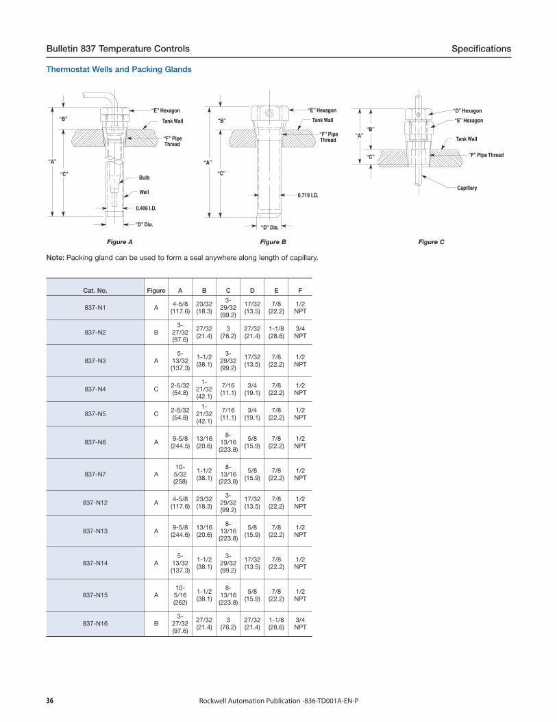
36 Rockwell Automation Publication -836-TD001A-EN-P
Bulletin 837 Temperature Controls Specifications
Thermostat Wells and Packing Glands
“E” Hexagon
Tank Wall
“F” Pipe Thread
Bulb
Well
0.406 I.D.
“D” Dia.
Figure A
“E” Hexagon
Tank Wall
“F” Pipe Thread
“D” Dia.
0.719 I.D.
Figure B
“E” Hexagon
Tank Wall
“F” Pipe Thread
“D” Hexagon
Capillary
Figure C
Note: Packing gland can be used to form a seal anywhere along length of capillary.
Cat. No. Figure A B C D E F
837-N1 A 4-5/8(117.6)
23/32(18.3)
3-29/32(99.2)
17/32(13.5)
7/8(22.2)
1/2NPT
837-N2 B3-
27/32(97.6)
27/32(21.4)
3(76.2)
27/32(21.4)
1-1/8(28.6)
3/4NPT
837-N3 A5-
13/32(137.3)
1-1/2(38.1)
3-29/32(99.2)
17/32(13.5)
7/8(22.2)
1/2NPT
837-N4 C 2-5/32(54.8)
1-21/32(42.1)
7/16(11.1)
3/4(19.1)
7/8(22.2)
1/2NPT
837-N5 C 2-5/32(54.8)
1-21/32(42.1)
7/16(11.1)
3/4(19.1)
7/8(22.2)
1/2NPT
837-N6 A 9-5/8(244.5)
13/16(20.6)
8-13/16(223.8)
5/8(15.9)
7/8(22.2)
1/2NPT
837-N7 A10-5/32(258)
1-1/2(38.1)
8-13/16(223.8)
5/8(15.9)
7/8(22.2)
1/2NPT
837-N12 A 4-5/8(117.6)
23/32(18.3)
3-29/32(99.2)
17/32(13.5)
7/8(22.2)
1/2NPT
837-N13 A 9-5/8(244.6)
13/16(20.6)
8-13/16(223.8)
5/8(15.9)
7/8(22.2)
1/2NPT
837-N14 A5-
13/32(137.3)
1-1/2(38.1)
3-29/32(99.2)
17/32(13.5)
7/8(22.2)
1/2NPT
837-N15 A10-5/16(262)
1-1/2(38.1)
8-13/16(223.8)
5/8(15.9)
7/8(22.2)
1/2NPT
837-N16 B3-
27/32(97.6)
27/32(21.4)
3(76.2)
27/32(21.4)
1-1/8(28.6)
3/4NPT
Allen-Bradley, Rockwell Software, Rockwell Automation, and LISTEN. THINK. SOLVE are trademarks of Rockwell Automation, Inc.
Trademarks not belonging to Rockwell Automation are property of their respective companies.
Publication 836-TD001A-EN-P - September 2014 Copyright © 2014 Rockwell Automation, Inc. All rights reserved. Printed in the U.S.A.
Important User Information
Read this document and the documents listed in the additional resources section about installation, configuration, and operation of this equipment before you install, configure, operate, or maintain this product. Users are required to familiarize themselves with installation and wiring instructions in addition to requirements of all applicable codes, laws, and standards.
Activities including installation, adjustments, putting into service, use, assembly, disassembly, and maintenance are required to be carried out by suitably trained personnel in accordance with applicable code of practice.
If this equipment is used in a manner not specified by the manufacturer, the protection provided by the equipment may be impaired.
In no event will Rockwell Automation, Inc. be responsible or liable for indirect or consequential damages resulting from the use or application of this equipment.
The examples and diagrams in this manual are included solely for illustrative purposes. Because of the many variables and requirements associated with any particular installation, Rockwell Automation, Inc. cannot assume responsibility or liability for actual use based on the examples and diagrams.
No patent liability is assumed by Rockwell Automation, Inc. with respect to use of information, circuits, equipment, or software described in this manual.
Reproduction of the contents of this manual, in whole or in part, without written permission of Rockwell Automation, Inc., is prohibited.
Documentation Feedback
Your comments will help us serve your documentation needs better. If you have any suggestions on how to improve this document, complete this form, publication RA-DU002, available at http://www.rockwellautomation.com/literature/.
Rockwell Otomasyon Ticaret A.Ş., Kar Plaza İş Merkezi E Blok Kat:6 34752 İçerenköy, İstanbul, Tel: +90 (216) 5698400
Recommended