HD-L-TR-1952 WWApril 1981
04
Conformal and Small Antenna Designs,•
_1
By Howard S. Jones, Jr.
IZ1
U.S. Ar~ny Electronics Resa,,rch, znd Developmrtet Comt'oand
Harry Diamond Laborniorios
Adelpht, M, 2 ;C)783
c4')

- - ~The findiiip% iii thtk repi ut are not tri ht, c~mnti~ed ni :mo uciffivi1 1pu Ittiment ofr the! Armny 1~ts-iifit rnIu Srim wi detyh~leI by> Whlet
I ~~rrilhoreed dociumenits.
Citation of niinufactijrers' or trarde riuine' does not comfit hoenn official inclorswmemn or approvil0 of thec uw, th reof.
De~st roy 110% repotl wheri it Is iio I roger nieetdrd Do m' relurnit to the otipinilot.

SECURITY CLASSIFCTO OF THIS PAGE (Whe~n Data Enteed) I5RC!N
4. TflLE 2. GObttVT 4..*EL CA.q'-i~~OG NU OVERE
Conformal and Small Antenna Designsj. ,r ~- *....- ~. ~.~6., P.. 'vR.4 ORG. REPORT NUMBER
7. ATHOR5. ~~RACT OR GRANT NUMBER(*)
Howad8o(sJr
9. PERFORMING ORGANIZATION NAMAE AND ADIJRESS 10. PROGRAM ELEMENT, PROJECT, TASK
Harry Diamond Laboratories AE OKUI UBR
2800 Powder Mill RoadAdeihiMD 2783Program Ele: 6.11,U2.A
11. CONTROLLING OFFICE NAME AND ADDRESS
tArmy Research Office 18Research~~~pr Tragl9ak81 7793P.O. Box 12211 11. NUMBER OF PAGES
14. MONITORING AGENCY NAM~~.&.A-*ORXSS(I~f di fittra; fmControliod~ office) IS. SECURITY CLASS. (of thiis report)
Y~< UNCLASSIFIEDIS.. OECL ASSI Ic-ATi5`N/OOcw-NGRADING
SCHEDULE
III. DISTRIBUTION STATEMENT (of this Report)
Approved for public release; distribution unlimited,
17. DIS1TRIBUTION STATEMENT (of the abstract entered In Block 20, It different from Report)
18. SUPPLEMENTARY NOZTES
HDL Proj: 136112DROMS Code: 611102,00.00000
19. KEY WORDS (Continue on rve'-ere mide It' nsco~sary a-id Identify by block numnber)
Conformal CompactSmall microstrip Dielectric rod antennas4Edge slot Flush-mounted antennasRadiator Electrically small antannas
2Q. ABSTRAcr (camthm sae -rm al0ml M~ n~eweasse md idenltfy by block nimmber)
Select antennas are described that ca-i be used effectively on conformal surfaces. Most of theseantennas are compact, are electrica~ly and physically small, and can be easily Integrated Into conical andcylindrical bodies, Edge-slot, microstrip, and dlelectic rod radiator design techniques are emiployed in thedevelopment of these antennas. Critical design parametes-,, modes of radiation, empirical data, andthrcmaeticalcosidaretconsidere d.susd h nrni rprisad hrceitc fslce iltherimaeticals cosieratonsidare disusd.h nrni rprisad hrceitc fslce lc
DD 1473 eDtTIop or I NOV465 IS OSSOLEVEUN ASIED-
SECURITY CLASSIFICATION OF THIS PAGE (Ube Data Entered)
......................................................................................

UNCLASSIFIEDSECUR~ITY CLASSIFICATION op, THIS PAO;E(WhAI D.I. 5n107.d)
20. Abstract (Cont'd)
Several unique design configurations are Illustrated. Performance data on prototype antenna modelssuch as Impedance, gain, polarl7xation, radiation patterns, and bandwidth characteristics are presented.Salient features and advantages realized from the use of these design techniques are summarized.
UNCLASSIFIEDSECURITY CLASSIF'ICATION OF THIS PAGE(Whe.n fat. Enterod)
2

5 ~L(~ '01'r
CONTENTS ' '
D isJPage
1.INTRODUCTION .................. ............................................ ...... ...... 5
2. EDGE-SLOT RADIATORS ............................................................................. 5
2.1 Single Edge-Slot Radiator Characteristics ................................................... 62.1.1 Radiators in Bodies of Revolution .................................................... 72.1.2 Material Characteristics .............................................................. 7
2.2 Practical Edge-Slot Antenna Designs ..................... .................................. 72.2.1 Large and Small Edge-Slot Radiators ................................................ 92.2.2 Quadrature Edge-Slot Radiator ..................................................... 11
2.3 Arrays of Edge-Slot Radiators ............................................................... 112.3.1 Parallel Fed Antennas................................................................ 122.3.2 Series-Fed Antennas ................................................................. 13j
3. MICROSTRIP ANTENNAS .......................................................................... 13
3.1 Quarter-Wavelength Microstrip Radiator ................................................... 143.2 Conformal Microstrip Antenna Designs..................................................... 14
3.2.1 Two-Element Microstrip Antenna ................................................... 143.2.2 Dual Frequency Microstrip Arrays.................................................. 153.2.3 Multifunction Radome Antenna..................................................... 173.2.4 Spiral Microstrip Antenna ........................................................... 18
4. DIELECTRIC ROD ANTENNAS..................................................................... 20
4.1 Single Dielectric Rod Designs............................................................... 204.1.1 Decoupling Characteristics ......................................................... 204.1.2 Coaxial-Fed Dielectric Rod Radiator................................................ 204.1.3 Cylindrical Dielectric Rod Radiator ................................................. 22
4.2 Dielectric Rod Monopulse Antenna.................................................. ....... 234.3 Millimeter Wave Dielectric Rod Radiators.................................................. 234
5. OTHER DESIGNS.................................................................................... 24
6. CONCLUSION.............................................................. ......................... 24
DISTRIBUTION ........................................................................................... 29
3

q
FIGURES
Page
.1
1 J1 S ing le ed ge-slot rad ia to r ........... ...................................................................................... . . 62 Two-, four-, and eight-element edge-slot radiators .............................................................. 73 Frequency versus number of posts for multiple elements ................................................. 84 Radiation patterns of dual element edge-slot radiator at center of 8-in.-diameter cylinder... 85 Edge-slot telemetry antenna for Honest John Missile ......................................................... 96 Radiation patterns of telemetry antenna for HonestJohn Missile ..................................... 97 Four-e!ement conical edge-slot antenna with radiation patterns for 155-mm projectile ....... 108 Multifunction low-profile quadrature edge-slot uhf antenna ............................................ 11
9 Edge-slot radiator system designed into 40-mm projectile body and radiation patterns ....... 1210 Edge-slot array in conical body ......................................................................................... 1211 Series-fed antennas and transmission characteristics .................................................... 1312 B asic m icrostrip radiator ............................................................................................... . . 1413 Quarter-wavelength microstrip radiator .......................................................................... 14
14 Two-element microstrip telemetry antenna and radiation pattern .................................... 1515 Piggyback microstrip radiator ............................................................................................ 1616 Radiation patterns of piggyback antenna ........................................................................ 1617 Dual frequency radome antenna with radiation pattern of four-element array ................. 1718 Multifunction integrated radome antenna system ........................................................... 1819 Spiral-slot antenna mounted in nose of 2-m-long rocket .................................................. 1920 Radiation patterns of spiral-slot antenna In 2-m-long rocket ............................................ 1921 Gain-bandwidth (BW) characteristics of spiral-slot antenna .................... 1922 Single rod dielectric radiator and radiation patterns ......................................................... 2123 Decoupling as function of dielectric rod separation for three waveguide orientations .......... 2224 Radiation patterns of X-band coaxial-fed dielectric rod antenna in radome ..................... 2225 S-band dielectric rod radiator designed into small nose cone .......................................... 2226 Radiation patterns of small cylindrical dielectric radiator ............................................... 2327 X-hand dielectric rod monopulse antenna ........................................................................ 2428 Radiation patterns of X-band dielectric rod monopulse antonna, taken in ground plane ....... 2529 Millimeter wave dielectric rod radiator (70 GHz) with radiation patterns .......................... 2630 Millimeter wave dielectric rod radiators (94 GHz) ............................................................ 2731 Radiation patterns of millimeter wave antennas (94 GHz) ............................................... 2832 Small compact low-profile antennas ............................................................................... 28
I
S4

1. INTRODUCTION 2. EDGE.SLOT RADIATORS
Over the past few years, there has been an The edge-slot radiator design approach isincreasing interesi in the development and use a unique method used for designing antennaot efficient antenna systems that have certain systems that are functional and compatibledesirable characteristics and can be easily in- with conformal surfaces.1.4 The basic radiatortegrated into various shaped bodies, conform- is a thin structure usually in the form of a cir-ing to their outer surfaces. Equal attention has cular disk or a similar shape that consists ofbeen given to the need for reducing the size of two parallel conducting surfaces separated byantennas, especially in cases where there are a low-loss dielectric material and fed from aspace limitations and the antennas must be coaxial line. When the radiator is incorporatedconformal to surfaces, At first glance, satisfy- into a body such as a cone or a cylinder, itsing these requirements would appear to be a outer edge is intended to coincide wJth the sur-formidable task because, despite the dif- face of the body. This outer edge Is theficulties involved in achieving these goals, in radiating aperture. In the case of the circularmost antenna systems there can be no disk, the radiating aperture is circumferential,sacrifice in electrical performance. However, and -the radiation pattern is uniformly sym-
antenna systems that can be designed to in- metrical around the body.clude these features can solve many problemsand have numerous applications. Although most of the emphasis is focused
on the flat circular disk type radiator, there areAntenna research work performed at the modifications that include semicircular and
Harry Diamond Laboratories in recent years wedge shapes, as well as other design con-has been directed toward solving many of the figurations. Typical illustrations showing howdifficult problems. Both theoretical and ex- the edge-slot radiators are effectively used inperimental studies on antenna designs and bodies of revolution are included in other sec-material *9velopment were fully exploited. tions of this report.Other investigations included the determina-tion of certain overall system requirements, to Some of the features of edge-slot anten-effect optimum antenna performance that nas are as follows:would result in improvements over conven-tional antennas. From this research effort, a. They can be integrated quite well intoseveral unique conformal antenna designs conformal bodies.were conceived that made possible some _
antenna systems that are compatible with a 'Daniel H. Schaubert, Howard S. Jones, Jr., and Frank
variety of body shapes. Reggia, Conformal Dielectric-Fllled Edge-Slot Antennas forBodies of Revolution, Harry Diamond Laboratories HDL-TR- 1837 (September 1977).
This report summarizes much of the 2F. Reggia and H. S. Jones, Conformal Edge-Slotresearch and development effort involving cer- Radiators, U.S. Patent 4,051,480 (27 September 1977). J,
tain basic design techniques that are ap- 3 Daniel H. Schaubert, Howard S. Jones, Jr., and Frank
plicable to conformal and small antennas. The Fleggla, Conformal Dielectric-Filled Edge-Slot Antennas
results of the overall effort have made possible with Inductive-Post Tuning, IEEE Trans. Antennas Propag,,the antenna designs that are operational in the 27 (September 1979), 713-716.4Dipak L. Sengupta and Luls F. Martins-Camelo, Theoryultrahigh frequency (uhf) region through the of DielectrIc-F/lIed Edge-Slot Antennas, IEEE Trans. Anten-
millimeter wave frequency range. nas Propag., 28 (July 1980), 481-490.

b. Antenna systems can be designed in posts in certain positions across the parallelseveral frequency bands. conducting plates, the antenna characteristic
can be altered, particularly its impedance andc. Electronic scanning is possible. frequency of operation. An example of the
basic edge-slot radiator with inductive posts isd. The technique provides a simple shown in figure 1.
means of construction at low cost.Two-element, four-element, and
e. Radiation patterns from edge-slot eight-element antennas are shown in figure 2.radiators have good azimuthal symmetry. The number of elements in the radiator is
determined by the number of rows of inductive2.1 Single Edge-Slot Radiator posts.1.3 Also, the frequency can be affected by
Characteristics a change in the number of posts in the row.1Daniel H. Schaubert, Howard S. Jones, Jr., and Frank
In the previous section, a typical Reggia, ConformalDielectrlc-Fll~edEage.SlotAntennas for
edge-slot radiator is described as a compact Bodies of Revolution, Harry Diamond Laboratories HDL.
circular disk. This basic design operates at TR-1837 (September 1977).3Daniel H. Schaubert, Howard S. Jones, Jr., and Frank
some fundamental frequency, depending on its Reggia, Conformal Dielectric-Filled Edge-Slot Antennas
diameter and the dielectric material with Inductive-Post Tuning, IEEE Trans. Antennas Propag.,
characteristics. However, by placing inductive 27 (September 1979), 713-716.
INPUT CONNECTOR
COPPERCLAD
INDUCTIVE POSTSPLATED THROUGH
DIELECTRIC(TEFLON FIBERGLASS) cr 2.6
SOLDERED
Figure 1. Single edge-slot radiator.
6
X -. y- . .- , -

4.ELEMENT
.. . .. .--~.. ii•,u .. ,
.. . . . .. . . . . . ".... ,...... .. .. .. .. .
em.
Figure 2. Two-, four-, and eight-element edge-slot radiators.
Data illustrating frequency characteristics as a were used to design the individual radiators.function of the number of posts for multiple Typical dielectric materials used were low-losselements are shown in figure 3. Teflon fiberglass, epoxy glass, and silicone
glass laminates. Also, polystyrene foam dielec-
2.1.1 Radiators in Bodies of Revolution tric and selected inorganic dielectrics wereused for certain experiments. The dielectric
When used with typical weapon constant and the loss tangent of the materialsconfigurations, the edge-slot antenna can be were important design factors. Most of themounted conformally between portions of a materials lend themselves well to electrolessconducting body of revolution. Because the copperplating techniques used to provide the
aperture is very narrow and it couples strongly parallel conducting surfaces and the plated-to the body, full advantage can be taken of the through holes for the inductive posts.radiation properties of the antenna used onlarge and small structures. Furthermore, the 2.2 Practical Edge-Slot Antenna Designs
rotational symmetry of the antenna and the .1
body preserves the desired azimuthal sym- Because the edge-slot radiator canmetry of the radiation pattern. This symmetry be easily integrated into conformal surfaces, itcan be seen in the patterns of an 8-in. is used advantageously on both large and
(20.32-cm)-diameter, two-element edge-slot small bodies. The design technique Is oftenradiator mounted at the center of a 16-in. sought for use to satisfy critical electrical and(40.64-cm)-Iong cylinder shown in figure 4. mechanical problems. In some designs, prac-
tically no additional space is needed for the2.1.2 Material Characteristics antenna. The space saved is frequently used to
package electronic circuitry. This area is alsoIn most cases, copperclad dielec- isolated from the external radiation fields of the
tric laminated materials (printed-circuit boards) antenna.
7

3400 DIAMETER 7.6 cmITAICKNESS =3.18 mm (1/81N)
20 0.8 POST DIAMETER -1.9 mm300 POST SPACING - 4.0 mm
200 4 2 TEFLON FIBERGLASS711 3 0. SUBSTRATE
260 00 0 6 00- .
1800-4
1Z ~ ~ 1S 0.36
2200.- 150 210
-IN 4 IAONLY
Fiue4.0 aito0atrso ulelmn deso aitra cente of . c-n.lmtrcyidr
8 .
...................................o

I
_7%
.- ' . - r
?,. 5 IN. DIAM.
?4 EL EMENTSt-l o. *'. 1510 M14z1!8 IN TEFLON BETWEEN 1/8. IN. ALUMINUM
Figure 5. Edge-slot telemetry antenna for Honest John Missile.
2.2.1 Large and Small Edge-Slot 0 ....Radiators 330 30. ,,,o ........
It is sometimes difficult to obtain
the proper radiation coverage around a body 303W .A
(projectile or missile) employing conventionalantenna designs. The inherent properties ofthe edge-slot radiator allow full symmetricalradiation coverage around both large and A°° O oosmall bodies. A typical example is a 24.5-in.(62.23-cm) telemetry (TM) edge-slot antennadeveloped for use on an Honest John Missilefor multiple launch rocket system (MLRS)tests. A photograph of this antenna is shown infigure 5. Radiation patterns taken in both 2100 NOL
azimuthal and elevation planes are shown infigure 6. This antenna satisfied all radiationpattern requirements. Also, there was nosacrifice in structural integrity, and the design Figure 6. Radiation patterns of telemetrywas cost effective. anien'i . for Honest John Missile.
9
%5

The planar disk is not the only con- the aperture is at the base 3.33 cm from thefiguration for the edge-slot radiator. It can also apex. The space inside the nose cone isbe designed by using other shapes producing available for other circuiry.very good results. An example is the conicalshape edge-slot antenna shown in figure 7. Thirteen inductive posts separate
This four-element antenna is designed in the the elements and give an operating frequency
shape of a hollow nuse cone (copperplated of 6330 MHz with an impedance bandwidthdielectric) for use on an 81-mm projectile. The (voltage standing w4,,e ratio-VSWR 4 2) offeed is at the inside tip of the nose cone, and 150 MHz. Radiation patterns for this conical
edge-slot antenna also are shown in figure 7.CONICAL EDGE-SLOT ANTENNA The peak gain is directed in the forward region.
.. INPUT FEED
RADIATING ,APERTURE
155mm ROUND 00
'- .
3001 /240 331 30 330 0 0
go 2700 900oo, 2700
12o2400 1200 .2400
1210' 10180° 18001600 ELEVATION R AZIMUTHAL
PATTERN PATTERN1
.6 cm Eo(())q . 0°o " goo9
3 .3 T ,/ ' ' TTe•7.6€ cF - 6330 MH.
•.cm. Figure 7. Four-element conical edge-slot antenna with radiationpatterns for I •5-mm projectile.
V10

2.2.2 Quadrature Edge-Slot Radiator changes in the radiation patterns in thepresence of the radome
Figure 8 shows a novel low-profilf ,quadrature edge-slot ant3nna with polarization 2.3 Arrays of Edge-Slot Radiatorsd'versity and the capability of performingseveral functions.5 It consists of four confor- It has been shown that the frequencymal parallel plate edge-slot radiators (one in of an edge-slot radiator can be changed in aeach quadrant). Each radiator can be in- numbc. of different ways.' Also, further in-dependently excited in any phase relationship vestigations have indica(ed that diode devicesfor changing direction and polarization of the can be effectively employed to perform similar
i-," '~radiation field. The model shown in figure 8 is functions for array designs.2 These and other2-1/2 in. (6.35 cm) high and has a 5-in. techniques used for designinq multiple radiator(12.7-cm) diameter; it can be designed to systems have been developed. The advan-operate in the 600- to 700-MHz range. Also, tages derived from the use of edge-slotshown in the figure is the same antenna radiators in arrays, especially for smalldesigned into a hemispherical dielectric foam diameter bodies, have been quite beneficial."radome. Because the dielectric material has IDaniel H. Schaubert, Itoward S. Jones, Jr., and Frank'ow-loss characteristics, there are only slight Reggia Conformal Dielectric-Filled Edge-Slot Antennas fo
LBodies of Revolution, Harry Diamond Laboratories HDL.
T_._ _ 1837 (September 1977).5F. Reggia and H. S. Jones, Low Profile Quadrature-Plate 2F. Reggia and H. S. Jones, Conformal Edge-Slot
UHF Antenna, U.S. Patent 3,987,458 (19 October 1976). Radiators, U.S. Patent 4,051,480 (27 September 1977).
"L II• X.;
Figure 8. Multifunction low-profile quadrature edge-slot uf antenna
(a) with and (b) without radome. -

2.3.1 Parallel Fed Antennas Other edge-slot arrays containingas many as eight radiators have been
Secause edge-slot radiators are developed using corporate feed structures. Anthin and can be placed close together without array of edge-slot radiators currently beingphysical interference, they satisfy severe developed for use in a conical body is il-space requiremeints, while providing adequate lustrated in figure 10. Despite the differentradiation pattern coverage. Also, sometimes it diameters, each radiator can be designed tois necessary to design an antenna for a par- resonate at the same frequency. This type ofticular operating frequency with certain band- antenna can be designed for use as a fixedwidth requirements. In several cases, these re- angle system, monopulse array, or electroricquirements were satisfied with an edge-slot scanned array.antenna array fed in parallel. Figure 9(a) showstwo edge-slot radiators fed in parallel. Theantenna is incorporated into the forward sec-tion of a 40-mm projectile. It consists of eightelements and operates at 8300 MHz.
Radiation patterns of a singleradiator and the two radiators working Itogether, excited in phase and spaced one-halfwavelength (X/2) apart, are shown in figure 9(b).The impedance bandwidth (VSWR 4 2) of asingle antenna on the 40-mm mockup was ":1000 MHz (>12 percent). ~::~i!: i~~i;:..
kDOk4LOT RADIATORS
g , , x , /.1. 270 .
.4
IIADIATION PATTIES4NS4SINGLE ELEMENT E 4 DUAL ELEMENTS
Figure 9. Edge-slot radiator system designedinto 40-mm projectile body andradiation patternsv. Figure 10. Edge-slot ariay in conical body.
12
M -

2.3.2 Series-Fed Antennas with predicted operating frequencies for one-,two-, and three-post antennas. The radiation
Series-fed dielectric-filled edge- patterns of this multiradiator antenna are om-slot (SDE) antennas have been extensively in- nidirectional in the azimuthal plane. In thevestigated, and practical multifunctional elevation plane, the patterns are controlled bydesigns have resulted.6 A prototype design of the size of the cylinder and the locations of thean SDE antenna consisting of three radiators antennas on the cylinder.mounted in a 30.2-cm-long cylinder is shown infigure 11(a). The transmission and reflection Another version of the series-fedcharacteristics of this three-radiator model are antenna also is shown in figure 11(c). It depictsshown in the same figure. The dissipation max- two radiators (each with six radiating sections)ima at 675, 790, and 875 MHz (fIg. 1 1b) corres- stacked together, fed in series, and terminatedpond to transmission minima and agree well in a short circuit. By using a different number
of posts in each radiator, a thin dual frequency(a) antenna design with omnidirectional azimuthal
radiation coverage is possible.6
* 3. MICROSTRIP ANTENNAS
Until recently, very little had been pub-lished on the theory of microstrip radiators.However, the design technique is being in-creasingly used. A considerable amount of ex-
(b) perimental and oevelopment work has been10•[. -1_7 done, and a number of unique antenna designs
P 80 1 have been demonstrated. ,8 Modifications can, ' .be made easily to enhance its performance.
6r2 Notwithstanding the narrow bandwidth, these2- / •. -.• -•• microstrip radiators have been widely used in, /1/ - -- " .-- microwave antenna systems. Microstrip anten-
2° / - .nas are attractive because they are low profile,0 . .. . compact, lighweight, rugged, and easy to
600 700 g0 po oo fabricate, and they can be manufactured atFREQUENCY (MRz) low cost using printed-circuit techniques.
INPUT CONNECTOR
(C) COPPERPLATED
INDUCTIVE POSTS The basic rnicrostrip radiator is a thin-- PLATEDTHROUGH structure consisting of a rectangular conduc-PL.TE. "HROUG" ting patch that is mounted over a parallel
ground plane, excited by an inductive post fedfrom a coaxial line. The conducting patch isDIELECTRIC TOP VIEW
(TEFLON FIBERGLASS) SOLDERED usually approximately k/2 and separated from6D, Schaubert and H. S. Jones, Series-Fed, Dielectric-
"Filled, Edge-Slot Antenna, International Symposium Anten-
nas and Propagation, Seattle, WA (1979).7Robert E. Munson, Conformal Microstrip Antennas and
BOTTOM VIEW Mlcrostrip Phased Arrays, IEEE Trans. Antennas Propag.,AP-22 (January 1974), 74-78.
Figure 11. Series-fed antennas and 8John Q. Howell, Microstrip Antennas, IEEE Trans.transmission characteristics. Antennas Propag., AP-23 (January 1975), 90-93.
13
............................ ..................................

I,,
the ground plane by a thin low-loss dielectric TOP V I*1
material. Various widths (1/32, 1/16, and 1/8in.-O.3, 0.6, and 1.2 mm) of coppercladdielectric laminated materials are commonlyused in the construction of microstrip anten- DIELECTYICS
nas. An illustration of the basic microstrip EPOXYradiator is shown In figure 12. F,,,LO W.2.
TEFLON
3.1 Quarter-Wavelength Microstrip
Radiator _ AT.E,,I ELOD
Although much attention has been DIELECTRIC
given to the A/2 radiator, there are certain ad- _____/___/////CO'DUCTING
vantages realized from the use of the )J4 GROUNDPLNEINDUCTIVE POST ERO'VEV W
radiator. One of the chief benefits is that it con-serves space. The A/4 microstrip radiator is Figure 12. Basic microstrip radiator.shown in figure 13. It is short-circuited at oneend and fed at the center near the short circuit.Impedance matching the microstrip radiator isfairly easy; various techniques are used. The --- SLOTLENGTH• <,•/2
radiation patterns obtained from both A/4 and ,AoATN•SLOT-
)J2 radiators are very broad andtherefore quite -
useful for many applications. CONOUTO, IEPOXY
DIELECTRIC 1,14 1c3.2 CnomlMicrostrip Antenna FIBELCRGLASS 5.
Designs 4'.
The microstrip technique lends Itselfwell to the design of conformal antennas. ---
Because of the benefits derived from thisdesign approach, extensive effort has gone In-
HIGH RADIATION EFFICIENCYto experimental research to develop antennas INPUT Z APPROXIMATELY 50 Eoh,.
that are applicable to various weapon systems.As a result, several novel concepts and useful Figure 13. Quarter-wavelength microstripconformal antenna systems have been suc- radiator.cessfully designed. Illustrations and perfor-mance characteristics of some of these anten-
nas integrated into different body configura- minimal, and there is very little sacrifice in per-tions are included in the following sections. formance. Furthermore, it can be easily
designed into most conformal bodies that uselow-loss dielectrics. An example of a two-
3.2.1 Two-Element Microstrip Antenna element microstrip antenna design that
replaced a cavity-backed slot antenna isThe microstrip antenna is gradual- shown In figure 14. The azimuthal radiation
ly replacing the cavity-backed slot, stripline, pattern is shown in the same figure. In thisand waveguide cavity antennas because it re- case, all system requirements were satisfied Inquires less space, the construction cost is addition to the benefits cited above.
14
.... .. ..... .....

i 00
A T (l
a{
........
AZIMUTH Ev() W- 900
Figure 14. Two-eleme.it microstrip telemetry antenna and radiation pattern.
3.2.2 Dual Frequency Miorostrip Arrays signed Into the radome (copperplated on thesurface). Each of four elements of the array
A further indication of the exploita- consists of two radiators, one mounted on top
tion and increasing use of microstrip radiators of the other in a piggyback fashion. The bottomis observed in their successful application in radiator is a )J2 design, and the top radiator Is athe design of linear, planar, and conformal ar- )/4 design. The dielectric radome has a 0.2-inrays. Results of recent investigations have (0.5-cm)-thick wall, arid the inside of theshown that microstrip arrays can be integrated radome has complete copperplating, whichquite well into radome structures. Various provides the ground plane for the dualflush-mounted design configurations that are radiating elements. These elements that makecompatible with their body structures have up the array are excited in parallel from a cor-been demonstrated. porate feed.
The flu,:h-rnounted piggyback The A/4 section of the cual radiatormicrostrip antenna designed into a silicone has plated.through holes along its bottom
fiberglass radome cn a missile body Is i1- edge, which form the short circuit. An Inductive
lustrated9 in fliure 15. Here, four dual linear ar- post, which is also a plated-through hole,
rays, one array in 6a7h quadrant, are ee- matches the bottom )/2 radiator. In addition, Itprovides a passag3way to feed the )J4 radiator,
9H. S. Jones, D. Schaubert, and.'. Farrqr, Flushmounted as shown in figure 15. The elevation andPiggyback Microstrip Antenna, U.S. Patent 4,162,499 (24 azimuth plane radiation patterns of eachJuly 1979). radiator are shown in figure 16.
15

PIGGYBACK MCOTIRADIATOR ELEMENTS A IRADITORI
RADAFO
PARALL EL\DUAL FREQUENCY f~COPPER PLATE
ANTENNA ARRAY SURFACES RADIATOR
LA'SIDE VIEW TOP VIEW CROSS-SECTIONAL VIEW A.
REAR VIEW
Figure 15. Piggyback microstrip radiator.
PARALLEL PLATE1140 MHz
PATCHBOW MHz
2700 - 10 10- go2703 1 o
ELVTO ELANIE, AZIUT P ELANE lPWE
Adll
Figure 16. Radiation patterns of piggyback, antenna.
16
The desigi of a dual frequency forward end of military weapons. They providemicrostrip antenna Integrated into a section of a sound and rugged aerodynamic structuralconical radome is shownioin figure 17. This housing, within which is located antennaantenna consists of two linear arrays; one has systems, electronic hardware, and otherfour radiators and the other has eight. All of the devices. Efficient, functional antenna systemsradiators are A.4. Although the arrays operate can be designed and constructed into thesein different frequency bands, they are physical- radomes without having their structural integri-ly separated far enough to minimize mutual ty destroyed. A concept was conceived andcoupling. Furthermore, the elements In one developed that makes full use of the dielectricarray are staggered with respect to those In radome in the design of a multifunction anten-the other. This staggering provides additional na system.11,12decoupling between arrays. Radiation patternsof the four-element array also are seen in A typical example of this designfigure 17. concept is shown in figure 18. Here, the
parallel plate microstrip radiators are designed
3.2.3 Multifunctlon Radome AntennaI IH, S. Jones, Multi-FunctIon Integrated Radome-Anienna
Dielectric radomes of various System, U.S. Patent 4,010,470 (1 March 1977).
shapes and sizes are commonly used on the 12H. S. Jones, A Novel Technique for the Design of In-tegrated Radome-Antenna Systems, Proceedings of 13th
1oH. S. Jones, Multifrequency Antenna Integrated into a Symposium on Electromagnetic Windows (September
Radome, U.S. Patent 4,101,895 (18 July 1978). 1976).
loo . O 350
° d6 303500
, GAIN 5.5 dB • -
, \ W 3.0,• .
--- 2.03-7.
AII .
Fiue1.Da reunyrd, nenawt aito pattrno forelmn aray
17x-: --" --- - ELVTO
S... . '<:"": i] // ' - ' -.... PLANE "
i t, ~Figure 17. Dual frequency radome antenna with radiation pattern of four-element array. ,?:"'
-, ' • Z--

COPPERPLATED GRIDDED 3.2.4 Spiral Microstrip AntennaSURFACE
The spiral-slot antenna is an elec-trically small flush-mounted microstrip radiator
INSIDE COPPERPLATING designed for small-diameter missile or projec-tile applications.13 High radiation efficiency isobtained by strongly coupling radio frequency
DIELECTRICADOME (rf) currents to the body of a missile and ex-citing the dipole mode of radiation. When theantenna operates in the uhf band, an instan-
RADIATOSJ taneous bandwidth of approximately 2 percentis achieved. The spiral-slot antenna producesan axially polarized radiation field and a dipoleradiation pattern with Isotropic gain.
The antenna Is fabricated from acopperclad tube of epoxy fiberglass dielectric. "A thin rectangular sheet of conductor, wrappedin a tolral around the outer surface of a cylin-
Figure 18. Multifunction integrated radome drical tube of dielectric, forms the basic spiral-antenna system. slot antenna. In figure 19, the spiral-slot anten-
na Is shown in a typical application, mounted inthe nose tip of a 2-m-long rocket. The radiation
into the radome at the base and positioned at patterns from the antenna mounted on thepoints around the circumference. These )J4 body are shown In figure 20. The peak gain isradiators copperplated on the outer surface ex- about +1 dBi.tend around the base connecting with the in-side conducting surface (ground plane), where Main-polarized and cross-polarizedthey are excited from a coaxial probe near the radiation-pattern gains over a narrow frequen-base. The parallel plate radiators are designed cy range are plotted In figure 21. The spiral-slotto operate in the uhf region, antenna displays a 3-dB gain bandwidth of 9
MHz or approximately 3 percent. The instan-taneous impedance (VSWR - 2:1) bandwidth Ispletely copperplated except for the forward 4 MHz or about 2 percent. The cross-polarized
region of the cone, which is a conductive grid- field component Is at least 9 dB down andded surface. This dielectric loaded gridded decreases to about 14 dB down at the designregion can be designed to act as a spatial filter. center frequency (238 MHz).That Is, it is transparent to transmission at cer-tain frequencies; for example, at X-band,energy can be transmitted through the mediumwith minimum loss and distortion. Yet, at the'ow frequencies (uhf), this region is opaque totransmitted energy. These design features 1aD. H. Schaubert, A. R. Slndorls, and F. G. Farrar, The
Spiral Slot, a Unique Microstrip Antenna. Proceedings ofallow the radome antenna (fig. 18) to serve a 1978 Antenna Applications Symposium, University of II.variety of functions. Ilnols, Monticello, IL (October 1978).
18
41 ,

r7
•3 •r•SPIRAL-SLOT ANTENNA
Figure 19. Spiral-slot antenna mounted innose of 2-m-long rocket.
Oft 0" ANTENNA ON CYLINDRICAL TESIT SECTIOPI
AXIAL POLARIZA] IONS(MAIN)
b I
STRANSVIERSEPOLARIZATION
1010"
ON IROAC T ILI§"• •
231 , MMI
' 1W FREQUENCY WWHI)
'I
Figure 20. Radiation patterns of spiral-slot Figure 21. Gain-bandwidth (BW)character-antenna in 2-m-long rocket. istics of spiral-slot antenna.
19 ;
.4 '" "~ ANEN ON... CYL ....N.. .....A. .- T"-ST SEC"TIOI-!-' -"

i
4. DIELECTRIC ROD ANTENNAS 4.1.1 Decoupling Characteristics
The theory of dielectric rod radiators is Because the energy tends towell known.14 They are highly suited for use in adhere to the rod, there is very little coupling ofmilitary weapon systems to perform a variety energy between rods placed close together.1oof functions. These end-fired radiators have Two radiators were used with three differenthigh gain, low side lobes, high decoupling be- orientations of their beectric fields to determinetween radiators, and in some cases broad the decoupling characteristics betweenbandwidth characteristics. They are efficient radiators as a function of separation. Thewith good directivity and can be compactly results of this experiment are shown in figuredesigned into small apertures. Because of 23. Here, it is observed that when two rods arethese and other features, dielectric rod separated by only 1 In. (2.54 cm) and polarizedradiators offer many advantages when used in in the same plane, the decoupling is greaterthe design of small and conformal antennas. than 30 dB. In one orientation, as much as
70-dB decoupling is obtained.4.1 Single Dielectric Rod Designs
4.1.2 Coaxial-Fed Dielectric Rod
A considerable amount of research Radiatorand development has been performed ondielectric rod radiators operating In the X-band Dielectric rod radiators can beregion.15 Although a number of different designed sin'ply and effectively by feeding thematerials can be used as dielectric rod rod from a coaxial input; however, the band-radiators, the material that is used most often width is narrow. In this case, a portion of oneis aluminum oxide (AI 30,). It has a dielectric end of a cylindrical dielectric rod is metallizedconstant of 9.0 and a loss tangent of 0.0011. (or copperplated). The rod is fed from this
enclosed metallized end by a coaxial lineThe use of waveguide is a simple and whose center probe extends into the dielectric.
convenient means of launching a wave into the The other unbound end of the cylindrical rod isdielectric rod. In this case, the waveguide Is tapered to match the radiated energy to freeoperated In its dominant TEo mode, and as the space. An X-band dielectric rod radiator de-wave passes into the rod it is transformed into signed and constructed In this manner with itsthe hybrid mode of the rod.5 A dielectric rod radiation pattern is shown in figure 24. Thisradiator design using X-band waveguide is radiator is mounted in a circular ground planeshown in fliure 22. The dielectric rod is and is housed in a small conical radome.tapered to a point at one end for matching tothe waveguide. A more gentle taper is on the Another coaxial-fed dielectric rodoutput end to provide a smooth transfer of the radiator design that operates at 3.0 GHz Isenergy to space. The lossless dielectric foam shown in figure 25. This small antenna wasseen in figure 22 is used to position the rod in designed for use in a projectile nose cone con-the center of the waveguide. Shown in the formal with its apex. The overall length of thesame figure are elevation and azimuth plane antenna is about 2 In. (5.08 cm), and it providesradiation patterns taken at 9.0, 9.2, and 9.4 broad radiation coverage in the forward direc-GHz. tion.
14D. F, Halliday and D. G. Kiely, Dielectric-Rod Aerials,IEEE J., 94 (1947), Part IiA, 610-618.
15Howard S. Jones, Jr., Design and Development ofDielectric Rod Antennas, Harry Diamond Laboratories 1H. . Jones, Dielectric Rod Antenna System, U.S. Pa-
HDL- TR-1640 (July 1973). tent 3,858,214 (31 December 1974).
20

4L
9.0 GHz 9.2 GHz 9.4 GHzGAIN 10dB
100 0' 3500 100 00 3500 100 00 3500
300 \1.15 ~-3300' 300 \1530 300 -- N 5 3300
5 ~-
,oo I .° ,oo . ,o,-0 G0 0.0
500 3100 .0/ 310 500 3100
900 2700 900o 2700 -2700
9.0 GHz 9.2 GHz 9.4 GHZS..GAIN 10 dB
100 00 3500 100 00 3500 100 00 35004
300 15 3300 300 15 3300 3001 3300
-~-:
60 05 ~ .~ 3000 0 o 3100
700 500310
702900 700 q, 2900 700 2900
902700 900 2700 900 2700
II
Figure 22. Single rod dielectric radiator and radiation patterns.
21
. . .3 ..

70t IV.• 0° 350°
60-
o0310
0-500
0U0
030-
21 / • EE. PLANEH ....H PLANE20,.,.--- d ' FREQ 9.376 GHz
DIELECTRIC RADOME DIELECTRIC ROD
I-4-DIROFECTIELD COfPPLRPLAý. DIELECTRIC FOAM
Fiue2.LI- -I I ; GROUNOPLANE -INPUT0 1 2 3 4
SEPARATION, d UNA
Figure 23. Decoupling as function of Figure 24. Radiation patterns of X-banddielectric rod separation for coaxial-fed dielectric rodthree waveguide orientations. antenna in radome.
4.1.3 Cylindrical Dielectric Rod Radiator
The cylindrical dielectric antennawas designed to be small, compact, andcapable of producing a radiation pattern with -
the null on axis. This antenna is a 1-In.-high - - -"
dielectric (machinable glass) cylinder with a1/16-in. (0.6-mm) wall with a solid base on oneend and open on the other end. It is completelycopperplated on the Inside On the outside, thebase and only a small portion of the outer sur-face are copperplated. The copperplateddielectric structure is fed from coaxial line at ithe center of the base and is mounted in a2-112-In. (6.35-cm) circular groond plane.Figure 26 sketches a prototyrr:p model. In the . '
same figure are radiation patterns, one taken - -
with a thin absorber over the ground plane andthe other taken without the absorber. There areother versions of this antenna currently under Figure 25. S-band dielectric rod radiatorinvestigation, designed into small nose cone.
22
-- - - -- -

WITH ABSORBER OVER CIRCULAR DISK W/O ABSORBER0o 00
20 0 3400 20 .340°
I.270
g0oo 2700
10 CYLINDRICAL
CIRCULAR DISK DIELECTRIC ROD RADIATOR
(GROUND PLANE) &k I COPPERPLATING"7ký
INPUT FEED
Figure 26. Radiation patterns of small cylindrical dielectric radiator.
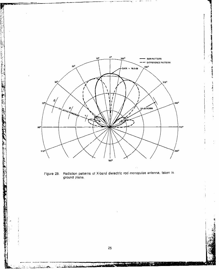
4.2 Dielectric Rod Monopulse Antenna 4.3 Millimeter Wave Dielectric RodRadlatt rs
A typical dielectric rod monopulseantenna Is illustrated in figure 27 (p. 24). The Single dieleciric rod radiatorsantenna consists of a hybrid tee, a dual 90-deg launched from waveguide have been designeadtwist to rotate the plane of polarization, and at 70 and 94 GHz. The experimental model oftwo H-plane tee junctions that support the the 70-GHz radiator with its radiation patternsfour dielectric rods. These rods are separated is shown in figure 29. This antenna uses a sap-approximately 1 In. The hybrid tee has two in- phire rod whose dielectric constant E,= 8.6 andputs: one feeds the two output channels In loss tangent tan J - 0.0014. The radiating"phase and the other feeds the output channels length of the rod is 0.75 in. (1.905 cm)out of phase. Each of these outputs (through measured from the waveguide (RG98/U) aper-the twist section) feeds a pair of rods that are ture.mounted in each series tee junction. This con-figuration allows each pair of rods to be ex- In the design of dielectric rods forcited In phase or out of phase with each other. operation at 94 GHz, two dielectric materialsFigure 28 (p. 25) shows the sum and difference were used, TPX (t, - 4) and custom HIK (E,patterns of the dielectric rod monopulse anten- 3.3). The radiating ends of the rods werena taken in a ground plane. designed In a pyramidal and tapered wedge
23
L7 ,.÷77 I'.i7

configuration (fig. 30, p. 27). The input endswere tapered to a point at the center to providean optimum match to the waveguide. Radiationpattern characteristics of these dielectric rodradiators are shown in figure 31 (p. 28). TheTPX wedge design had a peak gain of about 16dB.
5. OTHER DESIGNS
In addition to the antennas that have beendiscussed, modifications and other antennadesigns employ the same techniques and areuseful and noteworthy. Several of these anten-nas were designed into a small dielectric nosecone that is commonly used on projectiles.These are typical examples of electrically andphysically small antennas. In most cases,these antennas conform to the conical bodyand consume very little space. A selectedgroup of these small compact antennas and abrief description of each are shown in figure 32(p. 28).
6. CONCLUSION
The antenna techniques discussed herehave many outstanding features. Each tech-nique lends itself to the design of conformaland small antennas. Also, with these tech-niques, antennas can be designed in severalfrequency bands, an additional advantage. Theantennas illustrated are efficient, functional,low cost, and capable of being used in a varietyof applications.
There has been increasing interest in con-formal and small antennas. For example, thecontinued use of microstrip radiators in planar,conformal, and phased arrays has been heavi-
"I. . . ly emphasized. Further research and investiga-"tion into the use and exploitation of these andother techniques are continuing at the HarryDiamond Laboratories.
Figure 27. X-band dielectric rod monopulseantenna.
24 ':A
rI
0I100 0 3500 SUM PATTERN
IA _ _ 'A
6 00 10
25 1
WW __ __ __ __2900__ __

4ý
1 CIO 0
+13O
,-GAINIO PLA.E d
-7.
260
_-270.
1800 .

K.P
Figure 30. Millimeter wave dielectric rod radiators (94 GHz).
27
WA,
... .. .. .. .. .. .. .. .. .. .. NS

r0
FREQ 94 GHz
MATERIAL* Irk
_________ _______+ 16 dB1 SHAPE -WEDGE
10 -- + 15.6 dBi MATERIAL - TPX
MATE RIAL - CUSTOM Hi-K 6, =3.3
SHP -PRAI
IgIs
30
35
..900 _60n -30- 0 300 600 gooBEAM ANGLE (DEG)
Figure 31. Radiation patterns of millimeter wave antennas (94 GI-.z).
CONICAL EDOE.SLOT
RADIATOR~4 I
W ~PARALLEL PLATE~/2 MICROSTRIP MAGNEYICALLY TUNED X-BAND DIELECTRIC
RADIATOR RADIATOR HOD RADIATOR
TWO EDGE-SLOT PIGGYBACK DUAL CYIDIA DEETIRADIATORS FRkOUENCY RADIATOR ROD RADIATORSINTEGRATED INTOSMALL NOSE CONE
Figure 32. Small Compact low-profile antennas.
28
,, - _ >~. ...............< ,- .S :........

DISTRIBUTION
ADMINISTRATOR DEFENSE COMMUNICATIONS ENGINEERING CENTERDEFENSE TECHNICAL INFORMATION CENTER ATTN RES & DEVATTN DTIC-DDA (12 COPIES) 1860 WIEHLE AVECAMERON STATION, BUILDING 5 RESTON, VA 22090ALEXANDRIA, VA 22314
DIRECTORCOMMANDER DI:FENSE INTELLIGENCE AGENCYUS ARMY RSCH & STD GP (EUR) ATTN DEP DIR FOR SCI & TECH INTELLIGENCEATTN CHIEF, PHYSICS & NLATH BRANCH WASHINGTON, DC 20301FPO NEW YORK 09510
UNDERSECRETARY OF DEFENSE FOR RESEARCH &COMMANDER ENGINEERINGUS ARMY ARMAMENT MATERIEL ATTN RESEARCH & ADVANCED TECH
READINESS COMMAND ikTTN ELECTRONICS & PHYSICAL SCIENCESATTN DRSAR-LEP-L, TECHNICAL LIBRARY WASHINGTON, DC 20301ROCK ISLAND, IL 61201
ASSISTANT SECRETARY OF THE ARMYCOMMANDER RES, DEV, & ACQUS ARMY MISSILE & MUNITIONS CENTER & ATTN DEP FOR SCI & TECH
SCHOOL WASHINGTON, DC 20310ATTN ATSK-CTD-FREDSTONE ARSENAL, AL 35809 OFFICE OF THE DEPUTY CHIE OF STAFF FOR
RESEARCH, DEVELOPMENT & ACQUISITIONDIRECTOR ATTN DIR OF ARMY RES, DR. M. E. LASSERUS ARMY MATERIEL SYSTEMS ANALYSIS ATTN DAMA-AR, RESEARCH PROGRAMS
ACTIVITY WASHINGTON, DC 20310ATTN DRXSY-MPABERDEEN PROVING GROUND, MD 21005 COMMANDER
US ARMY COMMUNICATIONS RESEARCH &DIRECTOR DEVELOPMENT COMMANDUS ARMY BALLISTIC RESEARCH LABORATORY ATTN DR. FELIX SCHWERINGATTN DRDAR-TSB-S (STINFO) FT. MONMOUTH, NJ 07703ABERDEEN PROVING GROUND, MD 21005
COMMANDERUS ARMY ELECTRONICS TECHNOLOGY US ARMY MISSILE COMMAND
& DEVICES LABORATORY ATTN DRSMI-REG, MR. FAN KINGATTN VLET-DD ATTN DRSMI-O, ADV SYS CONCEPTS OFFICEFORT MONMOUTH, NJ 07703 REDSTONE ARSENAL, AL 35809
IIQ USAF/SAMI ARMY RESEARCH OFFICE (DURHAM)WASHINGTON, DC 20330 ATTN TrCH LIBRARY
P.O. BOX 12211TELEDYNE BROWN ENGINEERING RESEARCH TRIANGLE PARK, NC 27709ATTN DR. MELVIN L. PRICE, MS-44CUMMINGS RESEARCH PARK COMMANDER
HUNTSVILLE, AL 35807 US ARMY COMMUNICATIONS-ELECTRONICS
ENGINEERING INSTALLATION AGENCYENGINEERING SOCIETIES LIBRARY ATTN SCCC-CED-RPATTN ACQUISITIONS DEPARTMENT FORT HUACHUCA, AZ 85613345 EAST 47TH STREETNEW YORK, NY 10017 COMMANDER
US ARMY FOREIGN SCIENCE & TECHNOLOGYDIRECTOR CENTERDEFENSE ADVANCED RESEARCH PROJECTS AGENCY ATTN DRXST-SR-ZATTN DIR, TECHNOLOGY ASSESSMENTS OFFICE FEDERAL OFFICE BLDGARCHITECT BLDG 220 7TH STREET, NE1400 WILSON BLVD CHARLOTTESVILLE, VA 22901"ARLINGTON, VA 22209
29 i

DISTRIBUTION (CONT'D)
COMMANDER DIRECTOR
BMD SYSTEMS COMMAND AF OFFICE OF SCIENTIFIC RESEARCH
ATTN BMDSC-HR ATTN DIR OF ELECTRONIC & SOLID STATE SCIP.O. BOX 1500 ATTN DIR OF MATHEMATICAL & INFO SCIHUNTSVILLE, AL 35807 BOLLING AFB
WASHINGTON, DC 20332COMMMANDERNAVAL AIR SYSTEMS COMMAND DIRECTORDEPT OF THE NAVY NASA GODDARD SPACE FLIGHT CENTER
ATTN AIR-310B, J. WILLIS ATTN 250, TECH INFO DIVWASHINGTON, DC 20361 GREENBELT, MD 20771
COMMANDER DIRECTOR
'NAVAL OCEAN SYSTEMS CENTER AF AVIONICS LABORACORYATTN CODE 2000, ELECTROMAGNETIC SYS ATTN AFAL/TEM, MR. JOHN P. SHANKLIN, JR.SAN DIEGO, CA 92152 WRIGHT PATTERSON AEB, OH 45433
DIRECTOR COMMANDER
NAVAL RESEARCH LABORATORY AF CAMBRIDGE RESEARCH LALORATGRIAS, AFSC
ATTN CODE 5209, ANTENNA SYS ATTN CODE LZ, MR. P. BLACKS'vYTI!WASHINGTON, DC 20375 L. G. HANSCOM FIELD
BEDFORD, MA 01730COMMANDER
NAVAL SEA SYSTEMS COMMAND NATIONAL OCEANIC & ATMOSPHERIC ADMDEPT OF THE NAVY ENVIRONMENTAL PES LABSATTN NSEA-0333, WARHEAD & FUZE BR ATTN R-51, LIBRARYWASHINGTON, DC 20362 BOULDER, CO 80302
COMMANDER GENERAL DYNAMICSNAVAL SURFACE WEAPONS CENTER ATTN DR. GUN TRICOLES
ATTN G40, FUZES & GUIDANCE SYSTEMS DIV ELECTRONIC DIVISIONWHITE OAK, MD 20910 P.O. 81127
SAN DIEGO, CA 92138COMMANDERNAVAL WEAPONS CENTER AEROSPACE CORPORATION
ATTN CODE 31, SYS DEV DEPT ATTN MR. HOWARD KING
ATTN CODE 333, FUZE SYS DIV P.O. BOX 92957ATTN MR. GAYLON E. RYNO LOS ANGELES, CA 90009LJCHINA LAKE, CA 93555
RAYTHEON COMPANYCOMMANDER MISSILE SYSTEMS DIVISION
NAVAL UNDERWATex SYSTEMS COMMAND ATTN DR. RON LEWISNEW LONDON LABORATORY HARTWELL RDNEW LONDON, CT 015320 BEDFORD, MA 01730
COMMANDING OFFICER US ARMY ELECTRONICS RESEARCH
NAVAL MISSILE CENTER & DEVELOPMENT COMMANDATTN MR. CYRIL M. KALOI ATTN TECHNICAL DIRECTOR, DRDEL-CTPOINT MUGU, CA 93042 ATTN LEGAL OFFICE
COMMANDER HARRY DIAMOND LABORATORIESARMAMENT DEVELOPMENT & TEST CFNTER ATTN CO/TD/TSO/DIVISION DIRECTORS
ATTN DL, AF ARMAMENT LAB ATTN RECORD COPY, 81200ATTN DLM, GJIDED WEAPONS DIV ATTN HDL LIBRARY, 81100 (3 COPIES)EGLIN AFB, FL 32542 ATTN HDL LIBRARY, 81100 (WOODBRIDGE)
ATTN TECHNICAL REPORTS BRANCH, 81300
COMMANDING OFFICER ATTN CHAIRMAN, EDITORIAL COMMITTEENAVAL WEAPONS SUPPORT CENTER ATTN JXNES, H. S., 11200 (20 COPIES)ATTN MR. WILLIAM WHITTEDCRANE, IN 47522 ...
304
.... .... .... ... .... .... .... ...
Recommended