90 TRANSPORTATION RESEARCH RECORD 1128
Corps of Engineers Low-Volume Road Design
JOHN C. POTTER, RAYMOND S. ROLLINGS, AND WALTER R. BARKER
The U.S. Army Corps of Engineers' pavement design procedures are particularly appropriate for low-volume road applications because they were developed from traffic tests using relatively low traffic volumes and thin pavement sections on low-strength subgrades. The large loads and low volumes of traffic used in their development are especially analogous to situations encountered In mining, logging, and similar Industrial applications, or in port facilities. The flexible pavement criteria are most appropriate for thin asphalt concrete pavements in granular base courses and subbases. Generally, rigid pavements have not been associated with low-volume roads because of their cost. However, development of roller-compacted concrete pavement construction has made rigid lowvolume pavements feasible in many situations, and the corps design method is capable of addressing :roller-compacted concrete pavement characteristics. These design procedures, published in Army technical manuals, have also been computerized. The Corps of Engineers' design criteria can now be applied quickly and efficiently, even by pavement engineers unfamiliar with the corps criteria or programs, to design economical pavements for military installations and other lowvolume facilities.
The U.S. Army Corps of Engineers design procedures for roads and streets have been developed for application to the low traffic volumes generally associated with military installations. A central facet of the design criteria for both rigid and flexible pavements is a rational consideration of the structural requirements for pavements expected to experience limited traffic over their design life.
These design procedures have long been described in the various Army technical manuals. Now they have also been computerized. The computerized versions of the technical manuals allow faster and more error-free design. A wider range of structural design alternatives also becomes practical.
SCOPE
The design procedures for rigid and flexible pavements is the primary focus of this paper. These procedures were developed from traffic tests using relatively low traffic volumes and thin pavement sections on low-strength subgrades. The large loads and low volumes of traffic used in their development are especially analogous to situations encountered in mining, logging, and similar industrial applications, or in port facilities.
U.S. Army Corps of Engineers Waterways Experiment Station, P.O. Box 631, Vicksburg, Miss. 39180-0631.
The flexible pavement criteria are most appropriate for thin asphalt concrete pavements on granular base courses and subbases. Generally, rigid pavements have not been associated with low-volume roads because of their cost. However, development of roller-compacted concrete pavement construction has made rigid low-volume pavements feasible in many situations, and the corps design method is capable of addressing roller-compacted concrete pavement characteristics. Unsurfaced or aggregate-surfaced roads subject to heavy loads generally require continuous maintenance, even for low traffic volumes. The corps criteria for these roads are also less sophisticated than for rigid and flexible pavements and have not been computerized.
ROADS AND STREETS
A major element in any pavement design is the characterization of the anticipated traffic and selection of a design traffic loading. This task has been simplified in the corps criteria by use of a design index. The design index is a measure of the total lifetime traffic for the pavement in terms of equivalent 18-kip axle loads. Each design index corresponds to a range of equivalent 18-kip axle loads such as those given in Table 1. Pavements subjected to loads from vehicles such as forklift trucks or heavy aircraft, which are significantly greater than the 18-kip axle load, are designed separately. The use of 18-kip axle equivalents is not sufficiently accurate for these loads.
TABLE 1 FLEXIBLE PAVEMENT DESIGN INDEX AND RANGE OF EQUIVALENT 18-KIP AXLE COVERAGES
Flexible Range of Equivalent Coverages Pavement
(DI) Minimum Maximum
1 0 2,400 2 2,400 10,500 3 10,500 47,000 4 47,000 207,000 5 207,000 908,000 6 908,000 4,000,000 7 4,000,000 18,000,000 8 18,000,000 79,500,000 9 79,500,000 355,000,000
10 355,000,000 1,600,000,000
Norn: DI is design index.
The design index is determined in the same manner for both rigid and flexible pavements, except that the ranges of
Potter et al.
equivalent 18-kip axle coverages for each design index are different. (Here, a coverage is defined as a sufficient number of movements or passes of the design vehicle to cover the entire traffic lane with at least one stress repetition.) Traffic typical of a particular traffic category and facility class has been converted to equivalent 18-kip axle loads so that the appropriate design index can be selected knowing only the type of traffic (category) and roadway class. Additional guidance is provided, if needed, for selecting the category and class for a particular design.
The rural "road" or urban "street" class is a function of the design hourly volume (DHV), for the 25-year service life, as indicated in Table 2. The DHV is assumed to be 15 percent of the average daily traffic (ADT) for rural roads and 12 percent of the ADT for streets in built-up areas. Various geometric design constraints, appropriate for the traffic intensity, also apply to each class. Parking area design is based on Class E traffic.
TABLE 2 DESIGN HOURLY VOLUME AND ROAD/STREET CLASS
DHV
Class Road Street
A ~ 900 ~ 1,200 B 720-899 1,000-1,199 c 450-719 750-999 D 150-449 250-749 E 10-149 25-249 F < 10 < 25
The traffic category is governed by the number per day and gross weight of tracked vehicles, if any. Otherwise, the traffic category is based on the percentages of 2- and 3-axle trucks in the traffic mix. The descriptions for each category, and the design index corresponding to those categories for each class, are given in Table 3.
Thickness adjustment for traffic level has long been a part of Corps of Engineers pavement design. Both the rigid and flexible pavement design procedures are based on extensive fullscale, accelerated traffic testing to failure in a wide range of climates using a wide range of pavement structures and load configurations. These procedures have been highly refined for pavements subject to heavy aircraft loads and have been transferred to the design procedures for more lightly loaded pavements. These adjustments are based on actual field performance rather than laboratory tests. Environmental effects such as joint behavior, temperature and moisture cycles, and gradients and material variability, not normally accounted for by laboratory-determined design values, are implicitly incorporated.
Flexible Pavements
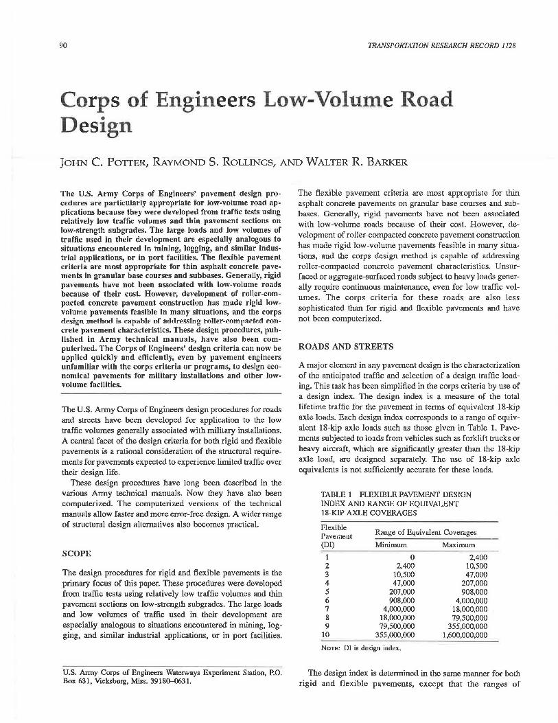
The flexible pavement design procedure is based on the California bearing ratio (CBR) equation and uses a thickness adjustment factor called the load-repetitions factor. Figure 1 shows the load-repetitions factor, a, as a function of 18-kip
91
axle coverages. The coverage level corresponding to the middle of the range of equivalent 18-kip axle loads for a particular design index (Table 1) is used to determine the appropriate a-factor.
Rigid Pavements
The Corps of Engineers' rigid pavement design method is based on a fatigue analysis. Tensile stress for the design load is calculated by using the Westergaard edge-loaded analytical model. When traffic loads will not actually "traffic" the free edge of a slab such as in parking areas or on airfields, these calculated stresses are reduced 25 percent to account for load transfer between adjacent slabs. Twenty five percent was selected as an appropriate design value from model and full-scale tests on pavements by using load transfer devices that met corps criteria. Pavements such as those on most roads and streets carry traffic loads adjacent to the outside free edge, and no reduction in stress is allowed for these.
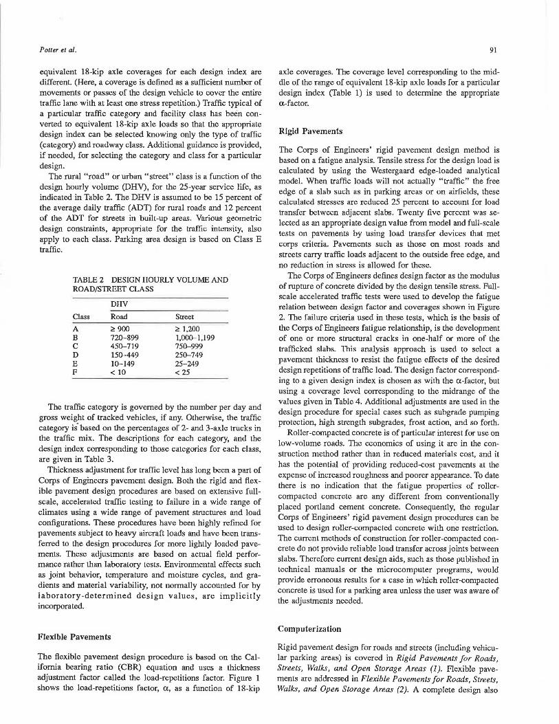
The Corps of Engineers defines design factor as the modulus of rupture of concrete divided by the design tensile stress. Fullscale accelerated traffic tests were used to develop the fatigue relation between design factor and coverages shown in Figure 2. The failure criteria used in these tests, which is the basis of the Corps of Engineers fatigue relationship, is the development of one or more structural cracks in one-half or more of the trafficked slabs. This analysis approach is used to select a pavement thickness to resist the fatigue effects of the desired design repetitions of traffic load. The design factor corresponding to a given design index is chosen as with the a-factor, but using a coverage level corresponding to the midrange of the values given in Table 4. Additional adjustments are used in the design procedure for special cases such as subgrade pumping protection, high strength subgrades, frost action, and so forth.
Roller-compacted concrete is of particular interest for use on low-volume roads. The economics of using it are in the construction method rather than in reduced materials cost, and it has the potential of providing reduced-cost pavements at the expense of increased roughness and poorer appearance. To date there is no indication that the fatigue properties of rollercompacted concrete are any different from conventionally placed portland cement concrete. Consequently, the regular Corps of Engineers' rigid pavement design procedures can be used to design roller-compacted concrete with one restriction. The current methods of construction for roller-compacted concrete do not provide reliable load transfer across joints between slabs. Therefore current design aids, such as those published in technical manuals or the microcomputer programs, would provide erroneous results for a case in which roller-compacted concrete is used for a parking area unless the user was aware of the adjustments needed.
Computerization
Rigid pavement design for roads and streets (including vehicular parking areas) is covered in Rigid Pavements for Roads, Streets, Walks, and Open Storage Areas (1). Flexible pavements are addressed in Flexible Pavements for Roads, Streets, Walks, and Open Storage Areas (2). A complete design also
92 TRANSPORTATION RESEARCH RECORD 1128
TABLE 3 PAVEMENT DESIGN INDEX
Pavement Design Index for Road or Street Classification
Traffic Categorl A B c D E F
I (< 1% two-axle trucks) 2 2 2 l l l II (S 10% 2-axle, no 3-axle trucks) 3 2 2 2 2 l III (S 15% trucks, S 1% 3-axle trucks) 4 4 4 3 3 2 IV (S 25% trucks, S 10% 3-axle trucks) 5 5 5 4 4 3 IVA (~ 25% trucks or ~ 10% 3-axle trucks) 6 6 6 5 5 4
v (60-kilopound (kip) track-laying vehicles):
500/day 7 7 7 7 7 * 200/day 6 6 6 6 6 * 100/day 6 6 6 6 6 6 40/day 6 6 6 5 5 5 10/day 5 5 5 5 5 5 4/day 5 5 5 5 4 4 l/dsy 5 5 5 4 4 4
VI (90-kip track-laying vehicles): 200/day 9 9 9 9 9 * 100/day 8 8 8 8 8 8 40/day 7 7 7 7 7 7 10/day 6 6 6 6 6 6 4/day 6 6 6 6 6 6 l/day 5 5 5 5 5 5 I/week 5 5 5 4 4 4
VII (120-kip track-laying vehicles): 100/day IO 10 IO IO IO IO 40/day 9 9 9 9 9 9 IO/day 8 8 8 8 8 8 4/dsy 7 7 7 7 7 7 I/day 6 6 6 6 6 6 I/week 5 5 5 5 5 5
* Traffic limited to IOO vehicles per day.
TABLE 4 RIGID PAVEMENT DESIGN INDEX AND RANGE OF EQUIVALENT 18-KIP AXLE COVERAGES
Rigid Pavement Design Index
1 2 3 4 5 6 7 8 9
10
Range of Equivalent Coverages
Minimum
1 45
600 13,000
130,000 800,000
3,500,000 14,000,000 40,000,000
110,000,000
Maximum
45 600
13,000 130,000 800,000
3,500,000 14,000,000 40,000,000
110,000,000 300,000,000
requires use of appropriate material from the technical manuals Pavement Design for Seasonal Frost Conditions (3) and General Provisions and Geometric Design for Roads, Streets, Walks, and Open Storage Areas. Having a working knowledge and understanding of the intricacies of these procedures are formidable tasks for a new corps employee or consultant designing a pavement for the Corps of Engineers. Errors of interpretation or application of the criteria or omissions of valuable options and considerations are easily committed. The
scrupulously precise logic of a computer program offers the potential for reducing errors of this kind. The increased computational speed makes consideration of a large number of potential pavement systems feasible.
The Corps of Engineers now has a series of computer programs for microcomputers that constitutes a high speed, friendly, interactive alternative to the technical manuals. Rigid pavement design for roads is covered by the RRD computer program, and flexible pavement design for roads is covered by the FRD program.
The two computer programs were developed specifically to operate on IBM PC's or compatible microcomputers using FORTRAN 77. Each of the programs has been uploaded to mainframe computers with only minimal effort. The computer programs were written to follow the design manual in a logical stepwise procedure. Questions are asked that must be answered so that all aspects of the design must be considered by the designer. In areas in which questions are not completely clear, accompanying information is provided. Also, when necessary, guidance in the selection of design data will be provided. The computer programs provide for a data review and a method of changing any design data before execution of the particular design problem. The programs determine pavement thicknesses and other pertinent design information that is consistent with the design manuals. The product from the program is first output to the screen and a disk file. The operator may then direct the output from the disk file to the printer.
gr w ~ Cl)
i ~ Cl z w a: t; a:· 0 t c u. z Cl ;;; w c
1.00
!:!
~ 0.80 t; c u. Cl)
~ j:: 0.80 j:: w 3; a: ~ 0.40 g
0.20
o L_..._..___..__.__......uu...&JL-~..___._..._.~~L----'L-_._~_._...LIJ'--~L-_._.L.....L_._.1~0".ooo~---''--..._ .............. 1~00~.000 10 100 1,000
2.0
1.5
1.0
COVERAGES
FIGURE 1 Load repetitions factor versus coverages.
1,000 10,000 100,000
COVERAGES OR LOAD CYCLES
1,000,000 10,000,000
FIGURE 2 Design factor versus coverage.

94
CONCLUSIONS
The Corps of Engineers design criteria are appropriate for low-. volume roads, especially if subjected to large wheel loads. The criteria can be used to design both flexible and rigid pavements, including roller-compacted concrete construction. Although the corps criteria are relatively complex, they have been incorporated into flexible and rigid pavement computer programs. These programs can be used on the microcomputer at the design engineer's desk to quickly design a selection of alternative pavement sections from which to choose the most economical section, confident that the Corps of Engineers design criteria are satisfied by each of the alternatives.
ACKNOWLEDGMEN'.f
The authors are grateful to the U.S. Army Engineers Waterways Experiment Station and the Office of the Chief of Engineers for administrative support and permission to publish
TRANSPORTATION RESEARCH RECORD 1128
this paper. The views of the authors do not purport to reflect the position of the U.S. Department of the Army or the U.S. Department of Defense.
REFERENCES
1. Rigid Pavements for Roads, Streets, Walks, and Open Storage Areas. Technical Manual 5-822-6. Department of the Anny. U.S. Government Printing Office, Washington, D.C., April 1977.
2. Flexible PavemenJs for Roads, Streets, Walks, and Open Storage Areas. Technical Manual 5-882-5. U.S. Government Printing Office, Washington, D.C., Oct. 1980.
3. Pavement Design for Seasonal Frost Conditions. Technical Manual 5-818-2. U.S. Government Printing Office, Washington, D.C., Jan. 1985.
4. General Provisions and Geometric Design for Roads, Streets, Walks, and Open Storage Areas. Technical Manual 5-822-2. U.S. Government Printing Office, Washington, D.C., April 1977.
Publication of this paper sponsored by Committee on on Low-Volume Roads.
Recommended