CREEP STRENGTH OF Ni-BASE SINGLE-CRYSTAL
SUPERALLOYS ON THE / ' TIE-LINE
T. Murakumo, Y. Koizumi, K. Kobayashi and H. Harada
High Temperature Materials 21 Project, National Institute for Materials Science,
1-2-1 Sengen, Ttsukuba, Ibaraki 305-0047, Japan
Keywords: Creep, Volume fraction, Rafting
Abstract
The creep strength of Ni-base single-crystal superalloys with
various ' fractions was investigated at 900˚C, 392MPa and
1100˚C, 137MPa. Creep strength of two-phase alloys was superior
to single phase alloys. It was shown that the optimum ’ volume
fraction depends on the temperature. The creep rupture lives were
the longest for the 70% ’ alloys at 900˚C, but they were obtained
at about 55% practical ’ fraction at 1100˚C. Changes in the
microstructure after creep rupture were studied. In ruptured
specimens, a raft structure perpendicular to the stress axis was
observed in the 40~60% ’ alloys. On the other hand, parallel
rafts were observed in the 80% ’ alloy. This parallel raft structure
could be explained by the change in the relative role between the
matrix and the dispersed phase.
Introduction
It was first reported by two of the authors[1, 2] that the creep
rupture life was the longest in the vicinity of 65% ' under anycreep condition in the polycrystalline Ni-base superalloyInconel713C. This tendency was expected to be observed in single-crystal superalloys, and, in fact, in the last two decades,
many studies had been carried out at around 60~70% ' fraction todevelop Ni-base superalloys. However, systematic studies have
not been reported about the effect of ' fraction for the strength of single-crystal superalloys. Generally, when the composition of each phase varies, it is difficult to evaluate the effect of the
changes in the ' fraction alone because the strength of each phaseand the lattice misfit should also be influenced. Therefore, as
tie-line single-crystal superalloys contain various ’ volumefractions, with each phase having the same composition, aninvestigation using these alloys was believed to produce results of great importance.
It is well known that the directional coarsening of ’, which is
called rafting, takes place in the creep of Ni-base superalloys at
high temperatures. Some observations imply that rafting reduces
the creep resistance [3~5] at temperatures below 1000˚C and at
higher stress. Therefore, modern Ni-base single-crystal
superalloys were developed with the addition of Re, because it
delays rafting despite the increased tendency to form topologically
close-packed (TCP) phases. Currently, higher temperatures are
required in practical applications of Ni-base superalloys, and it is
difficult to prevent rafting above 1000˚C. However, it is possible
to extend the creep rupture life with the formation of a stable raft
structure[6]. From this point of view, the fourth generation
superalloys[7, 8] were developed recently. The stable raft structure
can be obtained by a large lattice misfit that produces a dense
dislocation network on the / ’ interface. In this study, two creep
conditions at 900˚C and 1100˚C were selected to investigate the
effect of the ’ volume fraction in different creep behavior.
Experimental Procedures
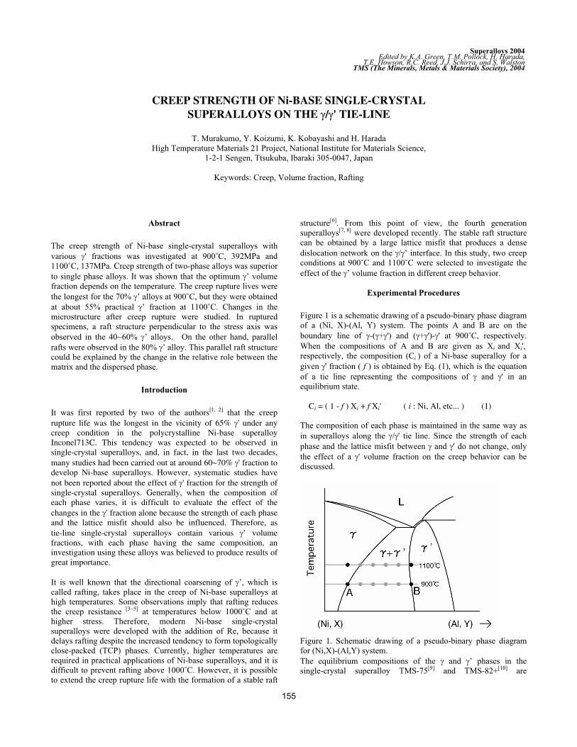
Figure 1 is a schematic drawing of a pseudo-binary phase diagram
of a (Ni, X)-(Al, Y) system. The points A and B are on the
boundary line of -( + ') and ( + ')- ' at 900˚C, respectively.
When the compositions of and B are given as Xi and Xi',
respectively, the composition (Ci ) of a Ni-base superalloy for a
given ' fraction ( f ) is obtained by Eq. (1), which is the equation
of a tie line representing the compositions of and ' in an
equilibrium state.
Ci = ( 1 - f ) Xi + f Xi' ( i : Ni, Al, etc... ) (1)
The composition of each phase is maintained in the same way as
in superalloys along the / ' tie line. Since the strength of each
phase and the lattice misfit between and ' do not change, only
the effect of a ' volume fraction on the creep behavior can be
discussed.
Figure 1. Schematic drawing of a pseudo-binary phase diagram
for (Ni,X)-(Al,Y) system.
The equilibrium compositions of the and ’ phases in the
single-crystal superalloy TMS-75[9] and TMS-82+[10] are
155
Superalloys 2004Edited by K.A. Green, T.M. Pollock, H. Harada,
TMS (The Minerals, Metals & Materials Society), 2004T.E. Howson, R.C. Reed, J.J. Schirra, and S, Walston
calculated by an alloy design program (ADP) developed at
NIMS[11], as shown in Table 1. ADP can estimate not only the
equilibrium composition of each phase and volume fraction but
also the lattice misfit, specific gravity, solution index (S.I.) value,
creep rupture life, and corrosion resistance. TMS-75 and 82+ are
third- and second-generation superalloys, respectively. In
comparisons with TMS-75, TMS-82+ contains less Re, but the
creep rupture life of TMS-82+ at 1100˚C is improved by
increasing the lattice misfit.
First, the and ’ single-phase alloys were cast as master alloys.
These alloys were mixed to make a series of single-crystal
superalloys, which had been designed to contain various volume
fractions of the ’ phase at 900˚C. The ’ fraction in each alloy
will decrease with increasing temperature above 900˚C, and, for
consistency, each alloy is henceforth referred to in terms of the
originally designed ’ volume fraction values, e.g., 20% ’. The
single crystals were produced in a directional solidification
furnace at NIMS in the form of bars with a diameter of 10 mm.
The longitudinal direction is near [001] in the 0~80% ’ alloys;
however, it is near [111] in the 100% ’ alloys, according to the
preferred growth direction of the primary crystal. Solution and
two-step aging heat treatment were carried out on each alloy
under optimum conditions for standard TMS-75, which contains a
63% ’ phase, as follows:
1300˚C/1h + 1320˚C/5h GFC(Gas Fan Cool)
1120˚C/5h GFC 870˚C/20h GFC
Constant-load tensile creep tests were performed at 900˚C,
392MPa and 1100˚C, 137MPa. After heat treatment and creep
rupture, SEM studies were carried out.
Microstructure after Heat Treatment
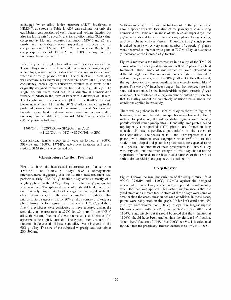
Figure 2 shows the heat-treated microstructure of a series of
TMS-82+. The 0~60% ’ alloys have a homogeneousmicrostructure, suggesting that the solution heat treatment was
performed fully. The 0% ’ fraction alloy consists mostly of a
single phase. In the 20% ’ alloy, fine spherical ’ precipitates
were observed. The spherical shape of ’ should be derived fromthe relatively larger interfacial energy as compared with theelastic strain energy in the case of smaller precipitates. This
microstructure suggests that the 20% ’ alloy consisted of only a phase during the first aging heat treatment at 1120˚C, and these
fine ’ precipitates were considered to have appeared during the
secondary aging treatment at 870˚C for 20 hours. In the 40% ’
alloy, the volume fraction of ’ was increased, and the shape of ’
appeared to be slightly cuboidal. The typical microstructure of amodern single-crystal Ni-base superalloy was observed in the
60% ’ alloy. The size of the cuboidal ’ precipitates was about200~500nm.
With an increase in the volume fraction of ’, the - ’ eutectic
should appear after the formation of the primary phase duringsolidification. However, in most of the Ni-base superalloys, the
- ’ eutectic should transform to a ’ single phase during cooling,
as drawn schematically in Figure 1. Therefore, this ’ single phase
is called eutectic ’. A very small number of eutectic ’ phases
were observed in interdendritic parts of 70% ’ alloy, and eutectic
’ increased as the increase of ’ fraction.
Figure 3 represents the microstructure in an alloy of the TMS-75
series, which was designed to contain an 80% ’ phase after heattreatment. Three kinds of microstructures were observed in
different brightness. One microstructure consists of cuboidal ’
and narrow channels, as in the 60% ’ alloy. On the other hand,
the / ’ structure is coarser, resulting in a visually matrix-like ’
phase. The wavy / ’ interfaces suggest that the interfaces are in a
semi-coherent state. In the interdendritic region, eutectic ’ was
observed. The existence of a large amount of eutectic ’ indicatesthat this alloy cannot be completely solution-treated under theconditions applied in this study.
There was no phase in the 100% ’ alloy as shown in Figure 2;
however, round and plate-like precipitates were observed in the ’
matrix. In particular, the interdendritic regions were densely
populated with round precipitates. Generally, precipitates, called
topologically close-packed (TCP) phases, are formed in long
annealed Ni-base superalloys, particularly in the cases of
Re-added alloys. The phases, , P, and R are reported as TCP
phases with different crystallographic structures[12, 13]. In this
study, round-shaped and plate-like precipitates are expected to be
TCP phases. The amount of these precipitates in 100% ’ alloy
was only 2%; thus the creep strength of this alloy should not be
significant influenced. In the heat-treated samples of the TMS-75
series, similar SEM photographs were obtained [14].
Creep Behavior
Figure 4 shows the resultant variation of the creep rupture life at
900˚C, 392MPa and 1100˚C, 137MPa against the designed
amount of ’. Some low ’ content alloys ruptured instantaneously
when the load was applied. This instant rupture means that the
yield stress and ultimate tensile stress of these alloys were same or
smaller than the creep stress under each condition. In these cases,
points were not plotted on the graph. Under both conditions, 0%
’ alloys were weaker than 100% ’ alloys. The longest rupture
life was obtained with the 70% ’ and 63% ’ alloys at 900˚C and
1100˚C, respectively, but it should be noted that the ’ fraction at
1100˚C should have been smaller than the designed ’ fraction.
When the ’ fraction of TMS-75 at 900˚C is 63%, it is calculated
by ADP that the practical ’ fraction decreases to 47% at 1100˚C.
156
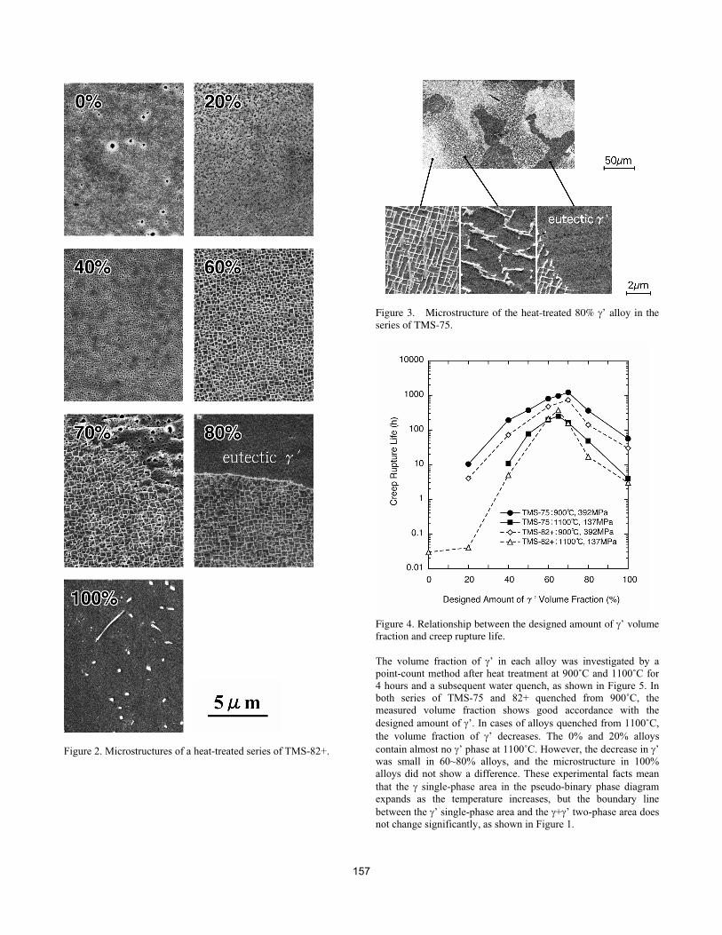
Figure 2. Microstructures of a heat-treated series of TMS-82+.
Figure 3. Microstructure of the heat-treated 80% ’ alloy in theseries of TMS-75.
Figure 4. Relationship between the designed amount of ’ volumefraction and creep rupture life.
The volume fraction of ’ in each alloy was investigated by a
point-count method after heat treatment at 900˚C and 1100˚C for
4 hours and a subsequent water quench, as shown in Figure 5. In
both series of TMS-75 and 82+ quenched from 900˚C, the
measured volume fraction shows good accordance with the
designed amount of ’. In cases of alloys quenched from 1100˚C,
the volume fraction of ’ decreases. The 0% and 20% alloys
contain almost no ’ phase at 1100˚C. However, the decrease in ’
was small in 60~80% alloys, and the microstructure in 100%
alloys did not show a difference. These experimental facts mean
that the single-phase area in the pseudo-binary phase diagram
expands as the temperature increases, but the boundary line
between the ’ single-phase area and the + ’ two-phase area does
not change significantly, as shown in Figure 1.
157
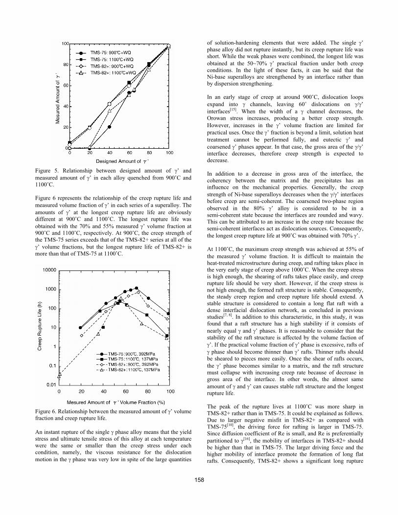
Figure 5. Relationship between designed amount of ’ and
measured amount of ’ in each alloy quenched from 900˚C and
1100˚C.
Figure 6 represents the relationship of the creep rupture life and
measured volume fraction of ’ in each series of a superalloy. The
amounts of ’ at the longest creep rupture life are obviously
different at 900˚C and 1100˚C. The longest rupture life was
obtained with the 70% and 55% measured ’ volume fraction at
900˚C and 1100˚C, respectively. At 900˚C, the creep strength of
the TMS-75 series exceeds that of the TMS-82+ series at all of the
’ volume fractions, but the longest rupture life of TMS-82+ is
more than that of TMS-75 at 1100˚C.
Figure 6. Relationship between the measured amount of ’ volume
fraction and creep rupture life.
An instant rupture of the single phase alloy means that the yield
stress and ultimate tensile stress of this alloy at each temperature
were the same or smaller than the creep stress under each
condition, namely, the viscous resistance for the dislocation
motion in the phase was very low in spite of the large quantities
of solution-hardening elements that were added. The single ’
phase alloy did not rupture instantly, but its creep rupture life was
short. While the weak phases were combined, the longest life was
obtained at the 50~70% ’ practical fraction under both creep
conditions. In the light of these facts, it can be said that the
Ni-base superalloys are strengthened by an interface rather than
by dispersion strengthening.
In an early stage of creep at around 900˚C, dislocation loops
expand into channels, leaving 60˚ dislocations on / ’
interfaces[15]. When the width of a channel decreases, the
Orowan stress increases, producing a better creep strength.
However, increases in the ’ volume fraction are limited for
practical uses. Once the ’ fraction is beyond a limit, solution heat
treatment cannot be performed fully, and eutectic ’ and
coarsened ’ phases appear. In that case, the gross area of the / ’
interface decreases, therefore creep strength is expected to
decrease.
In addition to a decrease in gross area of the interface, the
coherency between the matrix and the precipitates has an
influence on the mechanical properties. Generally, the creep
strength of Ni-base superalloys decreases when the / ’ interfaces
before creep are semi-coherent. The coarsened two-phase region
observed in the 80% ’ alloy is considered to be in a
semi-coherent state because the interfaces are rounded and wavy.
This can be attributed to an increase in the creep rate because the
semi-coherent interfaces act as dislocation sources. Consequently,
the longest creep rupture life at 900˚C was obtained with 70% ’.
At 1100˚C, the maximum creep strength was achieved at 55% of
the measured ’ volume fraction. It is difficult to maintain the
heat-treated microstructure during creep, and rafting takes place in
the very early stage of creep above 1000˚C. When the creep stress
is high enough, the shearing of rafts takes place easily, and creep
rupture life should be very short. However, if the creep stress is
not high enough, the formed raft structure is stable. Consequently,
the steady creep region and creep rupture life should extend. A
stable structure is considered to contain a long flat raft with a
dense interfacial dislocation network, as concluded in previous
studies[7, 8]. In addition to this characteristic, in this study, it was
found that a raft structure has a high stability if it consists of
nearly equal and ’ phases. It is reasonable to consider that the
stability of the raft structure is affected by the volume faction of
’. If the practical volume fraction of ’ phase is excessive, rafts of
phase should become thinner than ’ rafts. Thinner rafts should
be sheared to pieces more easily. Once the shear of rafts occurs,
the ’ phase becomes similar to a matrix, and the raft structure
must collapse with increasing creep rate because of decrease in
gross area of the interface. In other words, the almost same
amount of and ’ can causes stable raft structure and the longest
rupture life.
The peak of the rupture lives at 1100˚C was more sharp in
TMS-82+ rather than in TMS-75. It could be explained as follows.
Due to larger negative misfit in TMS-82+ as compared with
TMS-75[10], the driving force for rafting is larger in TMS-75.
Since diffusion coefficient of Re is small, and Re is preferentially
partitioned to [16], the mobility of interfaces in TMS-82+ should
be higher than that in TMS-75. The larger driving force and the
higher mobility of interface promote the formation of long flat
rafts. Consequently, TMS-82+ shows a significant long rupture
158
life when the practical ’ volume fraction is 55%.
Microstructure after Creep Rupture
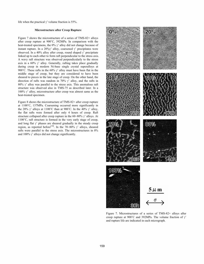
Figure 7 shows the microstructure of a series of TMS-82+ alloys
after creep rupture at 900˚C, 392MPa. In comparison with the
heat-treated specimens, the 0% ’ alloy did not change because of
instant rupture. In a 20% ’ alloy, coarsened ’ precipitates were
observed. In a 40% alloy after creep, round shaped ’ precipitate
linked up to each other to form raft perpendicular to the stress axis.
A wavy raft structure was observed perpendicularly to the stress
axis in a 60% ’ alloy. Generally, rafting takes place gradually
during creep in modern Ni-base single crystal superalloys at
900˚C. These rafts in the 60% ’ alloy must have been flat in the
middle stage of creep, but they are considered to have been
sheared to pieces in the late stage of creep. On the other hand, the
direction of rafts was random in 70% ’ alloy, and the rafts in
80% ’ alloy was parallel to the stress axis. This anomalous raft
structure was observed also in TMS-75 as described later. In a
100% ’ alloy, microstructure after creep was almost same as the
heat-treated specimen.
Figure 8 shows the microstructure of TMS-82+ after creep rupture
at 1100˚C, 137MPa. Coarsening occurred more significantly in
the 20% ’ alloys at 1100˚C than at 900˚C. In the 40% ’ alloy,
the flat rafts were formed after only 4 hours of creep. Raft
structure collapsed after creep rupture in the 60~80% ’ alloys. At
1100˚C, raft structure is formed in the very early stage of creep,
and long flat ’ phases are sheared gradually in the steady creep
region, as reported before[10]. In the 70~80% ’ alloys, sheared
rafts were parallel to the stress axis. The microstructures in 0%
and 100% ’ alloys did not change significantly.
Figure 7. Microstructures of a series of TMS-82+ alloys after
creep rupture at 900˚C and 392MPa. The volume fraction of ’
and rupture life are indicated in each micrograph.
159
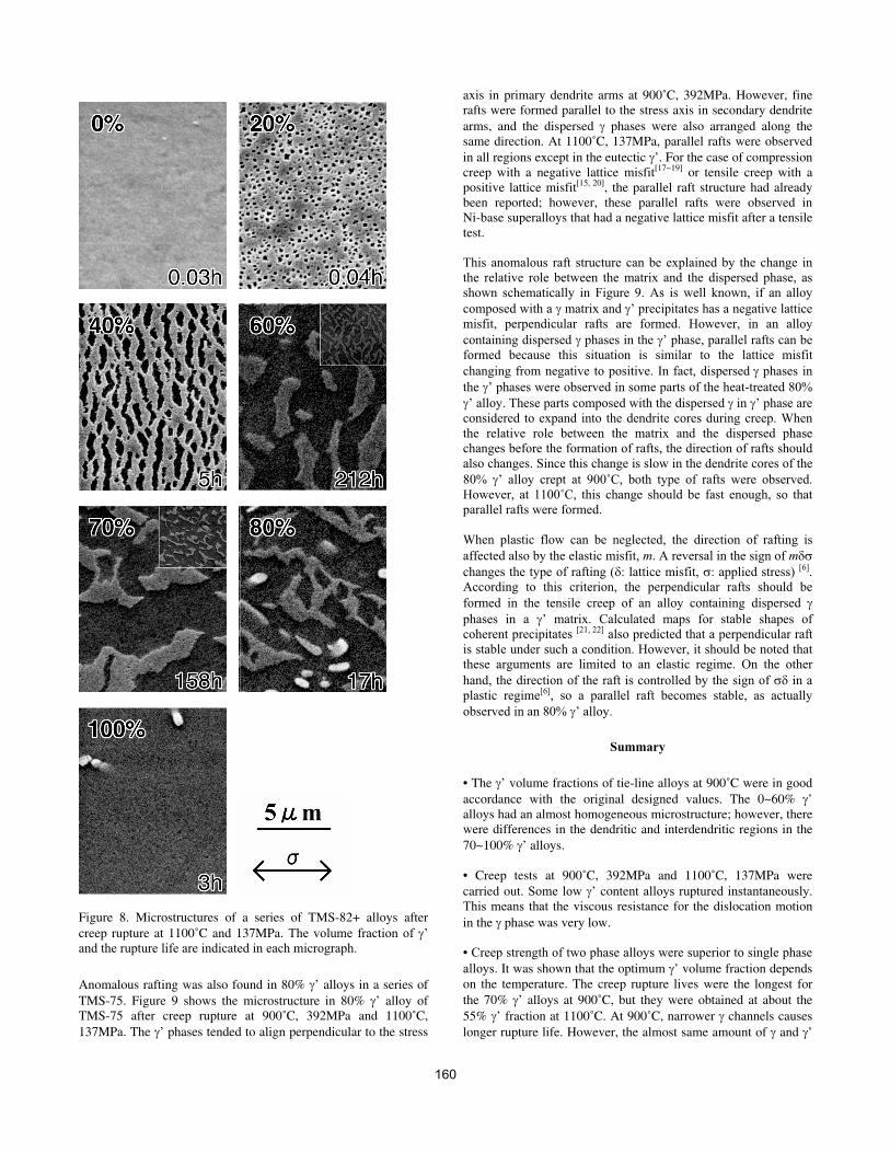
Figure 8. Microstructures of a series of TMS-82+ alloys after
creep rupture at 1100˚C and 137MPa. The volume fraction of ’
and the rupture life are indicated in each micrograph.
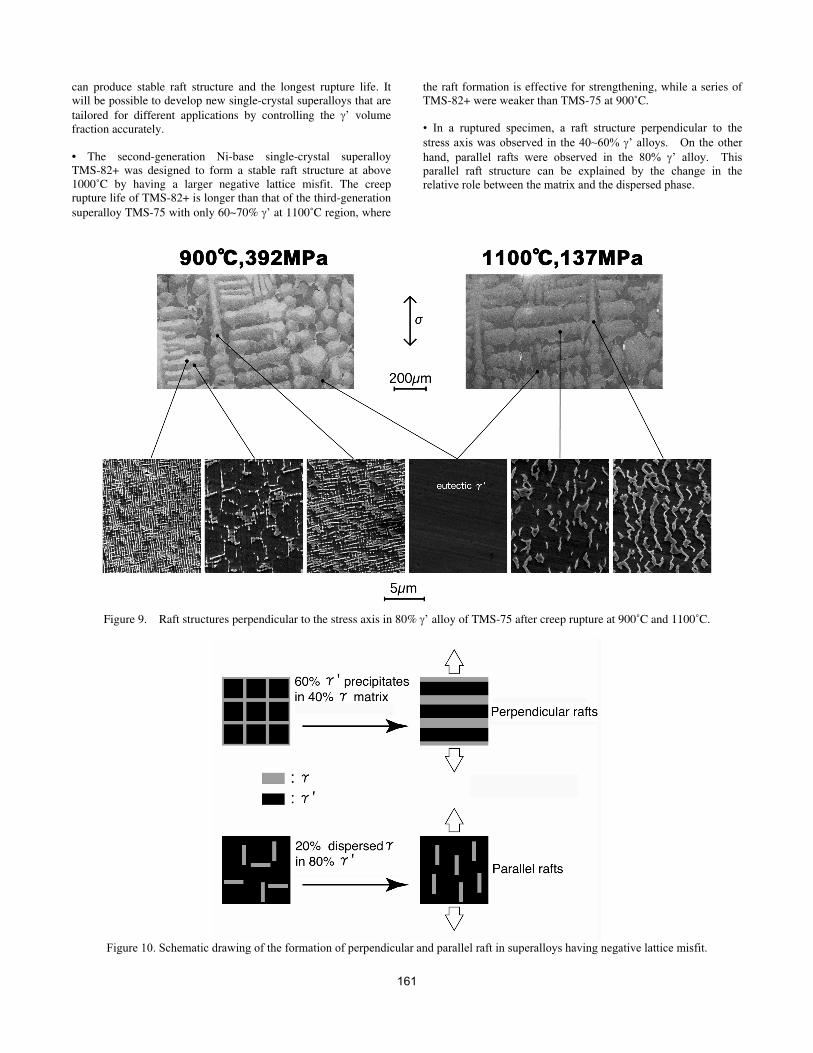
Anomalous rafting was also found in 80% ’ alloys in a series of
TMS-75. Figure 9 shows the microstructure in 80% ’ alloy ofTMS-75 after creep rupture at 900˚C, 392MPa and 1100˚C,
137MPa. The ’ phases tended to align perpendicular to the stress
axis in primary dendrite arms at 900˚C, 392MPa. However, finerafts were formed parallel to the stress axis in secondary dendrite
arms, and the dispersed phases were also arranged along thesame direction. At 1100˚C, 137MPa, parallel rafts were observed
in all regions except in the eutectic ’. For the case of compressioncreep with a negative lattice misfit[17~19] or tensile creep with apositive lattice misfit[15, 20], the parallel raft structure had alreadybeen reported; however, these parallel rafts were observed inNi-base superalloys that had a negative lattice misfit after a tensiletest.
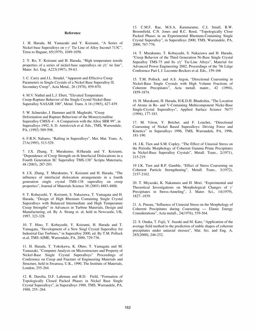
This anomalous raft structure can be explained by the change in
the relative role between the matrix and the dispersed phase, as
shown schematically in Figure 9. As is well known, if an alloy
composed with a matrix and ’ precipitates has a negative lattice
misfit, perpendicular rafts are formed. However, in an alloy
containing dispersed phases in the ’ phase, parallel rafts can be
formed because this situation is similar to the lattice misfit
changing from negative to positive. In fact, dispersed phases in
the ’ phases were observed in some parts of the heat-treated 80%
’ alloy. These parts composed with the dispersed in ’ phase are
considered to expand into the dendrite cores during creep. When
the relative role between the matrix and the dispersed phase
changes before the formation of rafts, the direction of rafts should
also changes. Since this change is slow in the dendrite cores of the
80% ’ alloy crept at 900˚C, both type of rafts were observed.
However, at 1100˚C, this change should be fast enough, so that
parallel rafts were formed.
When plastic flow can be neglected, the direction of rafting is
affected also by the elastic misfit, m. A reversal in the sign of m
changes the type of rafting ( : lattice misfit, : applied stress) [6].
According to this criterion, the perpendicular rafts should be
formed in the tensile creep of an alloy containing dispersed
phases in a ’ matrix. Calculated maps for stable shapes of
coherent precipitates [21, 22] also predicted that a perpendicular raft
is stable under such a condition. However, it should be noted that
these arguments are limited to an elastic regime. On the other
hand, the direction of the raft is controlled by the sign of in a
plastic regime[6], so a parallel raft becomes stable, as actually
observed in an 80% ’ alloy.
Summary
• The ’ volume fractions of tie-line alloys at 900˚C were in good
accordance with the original designed values. The 0~60% ’alloys had an almost homogeneous microstructure; however, therewere differences in the dendritic and interdendritic regions in the
70~100% ’ alloys.
• Creep tests at 900˚C, 392MPa and 1100˚C, 137MPa were
carried out. Some low ’ content alloys ruptured instantaneously.
This means that the viscous resistance for the dislocation motion
in the phase was very low.
• Creep strength of two phase alloys were superior to single phase
alloys. It was shown that the optimum ’ volume fraction depends
on the temperature. The creep rupture lives were the longest for
the 70% ’ alloys at 900˚C, but they were obtained at about the
55% ’ fraction at 1100˚C. At 900˚C, narrower channels causes
longer rupture life. However, the almost same amount of and ’
160
can produce stable raft structure and the longest rupture life. Itwill be possible to develop new single-crystal superalloys that are
tailored for different applications by controlling the ’ volumefraction accurately.
• The second-generation Ni-base single-crystal superalloyTMS-82+ was designed to form a stable raft structure at above1000˚C by having a larger negative lattice misfit. The creeprupture life of TMS-82+ is longer than that of the third-generation
superalloy TMS-75 with only 60~70% ’ at 1100˚C region, where
the raft formation is effective for strengthening, while a series of TMS-82+ were weaker than TMS-75 at 900˚C.
• In a ruptured specimen, a raft structure perpendicular to the
stress axis was observed in the 40~60% ’ alloys. On the other
hand, parallel rafts were observed in the 80% ’ alloy. This
parallel raft structure can be explained by the change in the
relative role between the matrix and the dispersed phase.
Figure 9. Raft structures perpendicular to the stress axis in 80% ’ alloy of TMS-75 after creep rupture at 900˚C and 1100˚C.
Figure 10. Schematic drawing of the formation of perpendicular and parallel raft in superalloys having negative lattice misfit.
161
Reference
1. H. Harada, M. Yamazaki and Y. Koizumi, “A Series of
Nickel-base Superalloys on - ’ Tie Line of Alloy Inconel 713C”, Tetsu to Hagane, 65(1979), 1049-1058.
2. Y. Ro, Y. Koizumi and H. Harada, “High temperature tensile
properties of a series of nickel-base superalloys on / ’ tie line”, Mater. Sci. Eng. A223(1997), 59-63.
3. C. Carry and J.L. Strudel, “Apparent and Effective Creep Parameters in Single Crystals of a Nickel Base Superalloy-II. Secondary Creep”, Acta Metal., 26 (1978), 859-870.
4. M.V. Nathal and L.J. Ebert, “Elevated Temperature
Creep-Rupture Behavior of the Single Crystal Nickel-Base
Superalloy NASAIR 100”, Metal. Trans. A 16 (1985), 427-439.
5. W. Schneider, J. Hammer and H. Mughrabi, “Creep Deformation and Rupture Behaviour of the Monocrystalline Superalloy CMSX-4 - A Comparison with the Alloy SRR 99”, in Superalloys 1992, S. D. Antolovich et al. Eds., TMS, Warrendale, PA, (1992) 589-598.
6. F.R.N. Nabarro, “Rafting in Superalloys”, Met. Mat. Trans. A, 27A(1995), 513-529.
7. J.X. Zhang, T. Murakumo, H.Harada and Y. Koizumi, “Dependence of Creep Strength on th Interfacial Dislocations in a Fourth Generation SC Superalloy TMS-138” Scripta Materiaria, 48 (2003), 287-293.
8. J.X. Zhang, T. Murakumo, Y. Koizumi and H. Harada, “The influence of interfacial dislocation arrangements in a fourth generation single crystal TMS-138 superalloy on creep properties”, Journal of Materials Science 38 (2003) 4883-4888.
9. T. Kobayashi, Y. Koizumi, S. Nakazawa, T. Yamagata and H. Harada, “Design of High Rhenium Containing Single Crystal Superalloys with Balanced Intermediate and High Temperature Creep Strengths” in Advances in Turbine Materials, Design and Manufacturing, ed. By A. Strang et. al, held in Newcastle, UK, 1997, 323-328.
10. T. Hino, T. Kobayashi, Y. Koizumi, H. Harada and T. Yamagata, “Development of a New Singl Crystal Superalloy for Industrial Gas Turbines,” in Superalloy 2000, ed. By T.M. Pollock et.al, TMS-AIME, Warrendale, PA, 2000, 729-736.
11. H. Harada, T. Yokokawa, K. Ohno, T. Yamagata and M. Yamazaki, “Computer Analysis on Microstructure and Property of Nickel-Base Single Crystal Superalloys” Proceedings of Conference on Creep and Fracture of Engineering Materials and Structure, held in Swansea, U.K., 1990, The Institute of Materials, London, 255-264.
12. R. Darolia, D.F. Lahrman and R.D. Field, “Formation of Topologically Closed Packed Phases in Nickel Base Single Crystal Superalloys”, in Superalloys 1988, TMS, Warrandele, PA, 1988, 255.-264.
13. C.M.F, Rae, M.S.A, Karunaratne, C.J, Small, R.W. Broomfield, C.N. Jones and R.C. Reed, “Topologically Close Packed Phases in an Experimental Rhenium-Containing Single Crystal Superalloy”, in Superalloys 2000, TMS, Warrandele, PA, 2000, 767-776.
14. T. Murakumo, T. Kobayashi, S. Nakazawa and H. Harada, “Creep Behavior of the Third Generation Ni-Base Single Crystal
Supealloy TMS-75 and Its / ’ Tie-Line Alloys”, Material for Advanced Power Engineering 2002, Proceedings of the 7th Liège Conference Part I, J. Lecomte-Beckers et al. Eds., 159-166
15. T.M. Pollock. and A.S. Argon, “Directional Coarsening in Nickel-Base Single Crystals with High Volume Fractions of Coherent Precipitates”, Acta metall. mater., 42 (1994), 1859-1874.
16. H. Murakami, H. Harada, H.K.D.H. Bhadeshia, “The Location of Atoms in Re- and V-Containing Multicomponent Nicke-Base Single-Crystal Superalloys”, Applied Surface Science 76/77 (1994), 177-183.
17. M. Véron, Y. Bréchet. and F. Louchet, “Directional Coarsening of Nickel Based Superalloys: Driving Force and Kinetics” in Superalloys 1996, TMS, Warrandele, PA, 1996, 181-190.
18. J.K. Tien and S.M. Copley, “The Effect of Uniaxial Stress on the Periodic Morphology of Coherent Gamma Prime Precipitates in Nickel-Base Superalloy Crystals”, Metall. Trans., 2(1971), 215-219.
19 J.K. Tien and R.P. Gamble, “Effect of Stress Coarsening on Coherent Particle Strengthening”, Metall. Trans., 3(1972), 2157-2162.
20. T. Miyazaki, K. Nakamura and H. Mori, “Experimental and
Theoretical Investigations on Morphological Changes of ’Precipitates in Stress-Anneling”, J. Mater. Sci., 14(1979), 1827-.1839.
21. A. Pineau, “Influence of Uniaxial Stress on the Morphology of
Coherent Precipitates during Coarsening --- Elastic Energy
Considerations”, Acta metall., 24(1976), 559-564.
22. S. Onaka, T. Fujii, Y. Suzuki and M. Kato, “Application of the
average field method to the prediction of stable shapes of coherent
precipitates under uniaxial stresses”, Mat. Sci. and Eng. A,
285(2000), 246-252.
162
Recommended