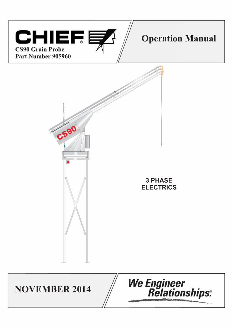
3 PHASEELECTRICS
CS90
Operation Manual
NOVEMBER 2014
CS90 Grain ProbePart Number 905960
Chief Agri/Industrial (800) 359-7600
Should you have any questions concerning assembly instructions, parts or drawings, please feel free to contact us at the following.
Chief Industries, Inc.Agri/Industrial Division
4400 East 39th Street Kearney, NE 68847PO Box 848 Kearney, NE 68848
Phone: 800.359.7600308.237.3186
Fax: 308.389.6703E-mail: [email protected]
For more information about Chief Industries, Inc. and additional products or services visit our website.
www.agri.chiefind.com
www.chiefind.com
“We Engineer Relationships”
Page 2
Chief Agri/Industrial (800) 359-7600
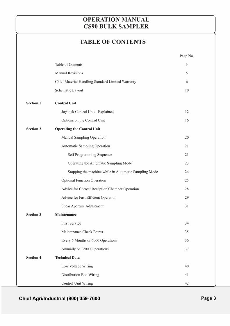
TABLE OF CONTENTS
Page No.
Table of Contents 3
Manual Revisions 5
Chief Material Handling Standard Limited Warranty 6
Schematic Layout 10
Section 1 Control Unit
Joystick Control Unit - Explained 12
Options on the Control Unit 16
Section 2 Operating the Control Unit
Manual Sampling Operation 20
Automatic Sampling Operation 21
Self Programming Sequence 21
Operating the Automatic Sampling Mode 23
Stopping the machine while in Automatic Sampling Mode 24
Optional Function Operation 25
Advice for Correct Reception Chamber Operation 28
Advice for Fast Efficient Operation 29
Spear Aperture Adjustment 31
Section 3 Maintenance
First Service 34
Maintenance Check Points 35
Every 6 Months or 6000 Operations 36
Annually or 12000 Operations 37
Section 4 Technical Data
Low Voltage Wiring 40
Distribution Box Wiring 41
Control Unit Wiring 42
OPERATION MANUALCS90 BULK SAMPLER
Page 3
TABLE OF CONTENTS
Section 5 Trouble Shooting 45
Section 6 Appendix
Service Record Sheet 50
Fault Diagnosis Questionnaire 51
OPERATION MANUALCS90 BULK SAMPLER
Chief Agri/Industrial (800) 359-7600
Page 4
Chief Agri/Industrial (800) 359-7600
OPERATION MANUALCS90 BULK SAMPLER
Manual Revisions
DATE REVISION MADE
11.1.2014 ADDED NEW DESIGN TEMPLATE ADDED CHIEF WARRANTY PAGE
Page 5
Chief Agri/Industrial (800) 359-7600
OPERATION MANUALCS90 BULK SAMPLER
CHIEF INDUSTRIES, INC.
AGRI/INDUSTRIAL DIVISION
CHIEF MATERIAL HANDLING STANDARD LIMITED WARRANTY
1. WHAT IS COVERED BY THIS STANDARD LIMITED WARRANTY If you are the original retail purchaser of Chief Industries, Inc. Material Handling (Elevators, Conveyors, Grain Probes, related accessories), Chief Industries, Inc. expressly warrants to you that the components manufactured by Chief Industries, Inc., were, on the date of delivery to you, free from defects in the composition of material, Chief Industries, Inc. workmanship, and design.
2. DURATION OF THIS STANDARD LIMITED WARRANTY AND NOTICE REQUIREMENTS
This Standard Limited Warranty is applicable under normal use and service to defects which become evident within a period of two (2) years from date of delivery of your Chief Industries, Inc.; Chief Material Handling equipment to you and which are reported in writing to Chief Industries, Inc. within 30 days of discovery of the defect. In any event, Chief's obligations under this Chief Material Handling Standard Limited Warranty shall expire twenty four (24) months from the invoice date.
In order to obtain warranty service, simply contact Chief Industries, Inc. in writing with the following information: (1) Your name; (2) Location of the product; (3) Dealer name; (4) Description of problem; (5) Any pertinent information; (6) Date of purchase (7) Original Invoice Number. No claim will be processed until all of this information has been received in writing by Chief Industries, Inc. For warranty service, contact Chief Agri/Industrial Division, P O Box 848, Kearney, NE 68848.
3. CHIEF'S OBLIGATIONS By purchasing from Chief Industries, Inc. your Chief Material Handling Equipment is subject to this Chief Industries, Inc. Chief Material Handling Standard Limited Warranty, you and Chief Industries, Inc. expressly agree to an allocation of the risks of product failure between you and Chief Industries, Inc. This allocation is recognized by both parties and is reflected in the price of the Chief Industries, Inc. Chief Material Handling Equipment.
4. REMEDIES AVAILABLE FROM CHIEF If a defect in your Chief Material Handling Equipment is covered by this standard limited warranty, Chief Industries, Inc. will supply replacement parts F.O.B. Chief Industries, Kearney, Nebraska for up to two years after date of purchase. In addition, during the first year of the warranty, Chief Industries, Inc. will supply labor necessary to make repairs in your Chief Material Handling Equipment. Chief Industries, Inc. will request at least two competitive bids for labor, as shall in the judgment of Chief Industries, Inc. be the most appropriate remedy for the failure covered by this warranty. Of course, Chief Industries, Inc. reserves the right to reject all such bids and to obtain additional bids. Upon acceptance of a bid by Chief Industries, Inc., Chief Industries, Inc. will authorize the necessary repair.
Page 6
Chief Agri/Industrial (800) 359-7600
OPERATION MANUALCS90 BULK SAMPLER
5. REMEDIES NOT AVAILABLE FROM CHIEF The obligations stated in the preceding paragraph are the SOLE AND EXCLUSIVE REMEDIES available from Chief Industries, Inc. in the event of problems with your Chief Material Handling will not be liable for the costs of dismantling defective parts or installing replacement parts, including labor costs, after the first ninety (90) days, and Chief Industries, Inc. will not be liable for any special, incidental or consequential damages based upon breach of warranty, breach of contract, negligence, strict tort, or any other legal theory.
6. WHAT IS NOT COVERED BY THIS CHIEF MATERIAL HANDLING STANDARD LIMITED WARRANTY
This Chief Material Handling Standard Limited Warranty does not cover:
(a) Chief manufactured product not sold as part of the Chief Material Handling Equipment.
(b) Products, components, equipment, accessories, or parts manufactured by someone other than
Chief Industries, Inc.
(c) Damage or loss during shipment of the Chief Material Handling Equipment.
(d) Damage or loss caused by the acts or omissions of the erector or his agents.
(e) Damage or loss caused, in whole or in part, by inadequate or improper site selection, inadequate or improper site preparation, inadequate or improper foundation, or any other failure to provide a suitable erection or installation environment for or a suitable erection or installation of the Chief Material Handling Equipment, or of any product, component, equipment, accessories, parts used in conjunction with the Chief Material Handling Equipment.
(f) Damage or loss caused, in whole or in part, by use of the Chief Material Handling Equipment for
purposes other than those for which it was designed. (g) Damage or loss caused, in whole or in part, by unauthorized attachments, modifications, or
alterations of the Chief Material Handling Equipment. (h) Damage or loss caused, in whole or in part, by improper or inadequate maintenance, misuse, or
abuse to the Chief Material Handling Equipment (i) Damage or loss resulting from conditions considered to be normal wear / tear from regular usage,
OR damages or loss resulting from usage of the Chief Material Handling Equipment for purposes other than the originally intended design.
Page 7
Chief Agri/Industrial (800) 359-7600
OPERATION MANUALCS90 BULK SAMPLER
7. NO OTHER WARRANTIES
(1) Complete and Exclusive Agreement: THIS AGREEMENT IS THE COMPLETE AND EXCLUSIVE AGREEMENT BETWEEN YOU AND CHIEF INDUSTRIES, INC., CONCERNING THE ALLOCATION OF THE RISKS OF DAMAGE OR LOSS ARISING FROM MANUFACTURED COMPONENT FAILURE. It supersedes all prior agreements, whether written or oral, and all other communications between you and Chief Industries, Inc. concerning the allocation of those risks. No employee of Chief Industries, Inc., or any other person, including Authorized Dealers and any other person authorized to sell Chief Material Handling Equipment, has any authority to make any representations, promises, or warranties in addition to those contained herein.
(2) THIS STANDARD LIMITED WARRANTY IS IN LIEU OF ALL OTHER WARRANTIES,
EXPRESSED OR IMPLIED, INCLUDING WARRANTIES OF MERCHANTABILITY AND FITNESS FOR A PARTICULAR PURPOSE.
8. ALLOCATION OF RISKS
THIS AGREEMENT ALLOCATES THE RISKS OF DAMAGE OR LOSS ARISING FROM PRODUCT FAILURE BETWEEN CHIEF INDUSTRIES, INC., AND PURCHASER. THIS ALLOCATION IS RECOGNIZED BY BOTH PARTIES AND WAS REFLECTED IN THE PURCHASE PRICE OF THE GOODS.
AGRI/INDUSTRIAL DIVISION
CHIEF INDUSTRIES, INC.
P. O. BOX 848
KEARNEY, NEBRASKA 68848
Page 8

Chief Agri/Industrial (800) 359-7600
This Page Is Intentionally Left Blank
Page 9
Chief Agri/Industrial (800) 359-7600
OPERATION MANUALCS90 BULK SAMPLER
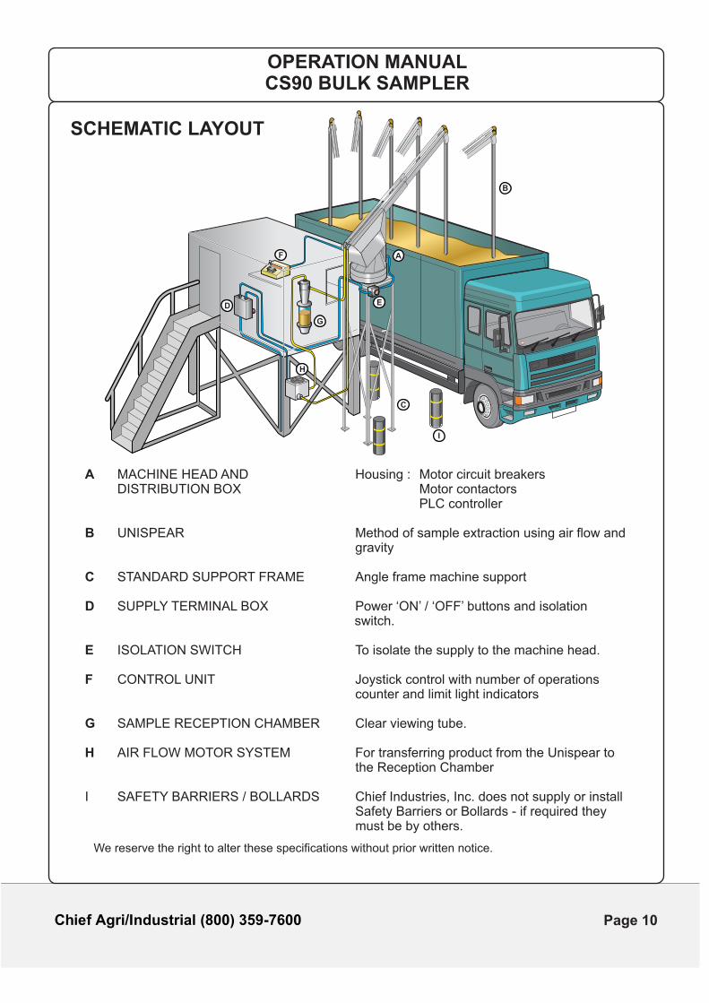
SCHEMATIC LAYOUT
A MACHINE HEAD AND Housing : Motor circuit breakers DISTRIBUTION BOX Motor contactors PLC controller
B UNISPEAR Method of sample extraction using air flow and gravity
C STANDARD SUPPORT FRAME Angle frame machine support
D SUPPLY TERMINAL BOX Power ‘ON’ / ‘OFF’ buttons and isolation switch.
E ISOLATION SWITCH To isolate the supply to the machine head.
F CONTROL UNIT Joystick control with number of operations counter and limit light indicators
G SAMPLE RECEPTION CHAMBER Clear viewing tube.
H AIR FLOW MOTOR SYSTEM For transferring product from the Unispear to the Reception Chamber
I SAFETY BARRIERS / BOLLARDS Chief Industries, Inc. does not supply or install Safety Barriers or Bollards - if required they
must b e by others.
We reserve the right to alter these specifications without prior written notice.
A
B
C
ED
F
G
H
I
Page 10

Chief Agri/Industrial (800) 359-7600
CS90
SECTION 1
CONTROL UNIT
OPERATION MANUALCS90 BULK SAMPLER
Page 11
Chief Agri/Industrial (800) 359-7600
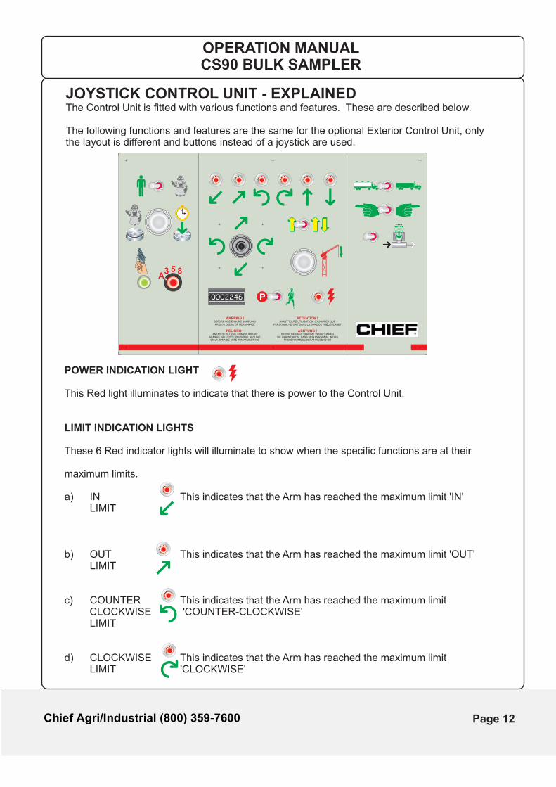
JOYSTICK CONTROL UNIT - EXPLAINEDThe Control Unit is fitted with various functions and features. These are described below.
The following functions and features are the same for the optional Exterior Control Unit, only the layout is different and buttons instead of a joystick are used.
P
WARNING !BEFORE USE ENSURE SAMPLINGAREA IS CLEAR OF PERSONNEL
ACHTUNG !BEVOR GEBRAUCHNAHME VERSICHEREN
SIE IHNEN DAVON, DASS KEIN PERSONAL IN DASPROBENAHMEGEBIET ANWESEND IST
ATTENTION !AVANT TOUTE UTILISATION, S’ASSURER QUE
PERSONNE NE SAIT DANS LA ZONE DE PR L VERNETÉ É
PELIGRO !ANTES DE SU USO, COMPRUEBESE
SIEMPRE NO EXISTE PERSONAL ALGUNO,EN LA ZONA DE ESTE TOMAMUESTRAS
A3 5 8
0002246
OPERATION MANUALCS90 BULK SAMPLER
POWER INDICATION LIGHT
This Red light illuminates to indicate that there is power to the Control Unit.
LIMIT INDICATION LIGHTS
These 6 Red indicator lights will illuminate to show when the specific functions are at their
maximum limits.
a) IN This indicates that the Arm has reached the maximum limit 'IN' LIMIT
b) OUT This indicates that the Arm has reached the maximum limit 'OUT' LIMIT
c) COUNTER This indicates that the Arm has reached the maximum limit CLOCKWISE 'COUNTER- CLOCKWISE'
LIMIT
d) CLOCKWISE This indicates that the Arm has reached the maximum limit LIMIT 'CLOCKWISE'
Page 12
Chief Agri/Industrial (800) 359-7600
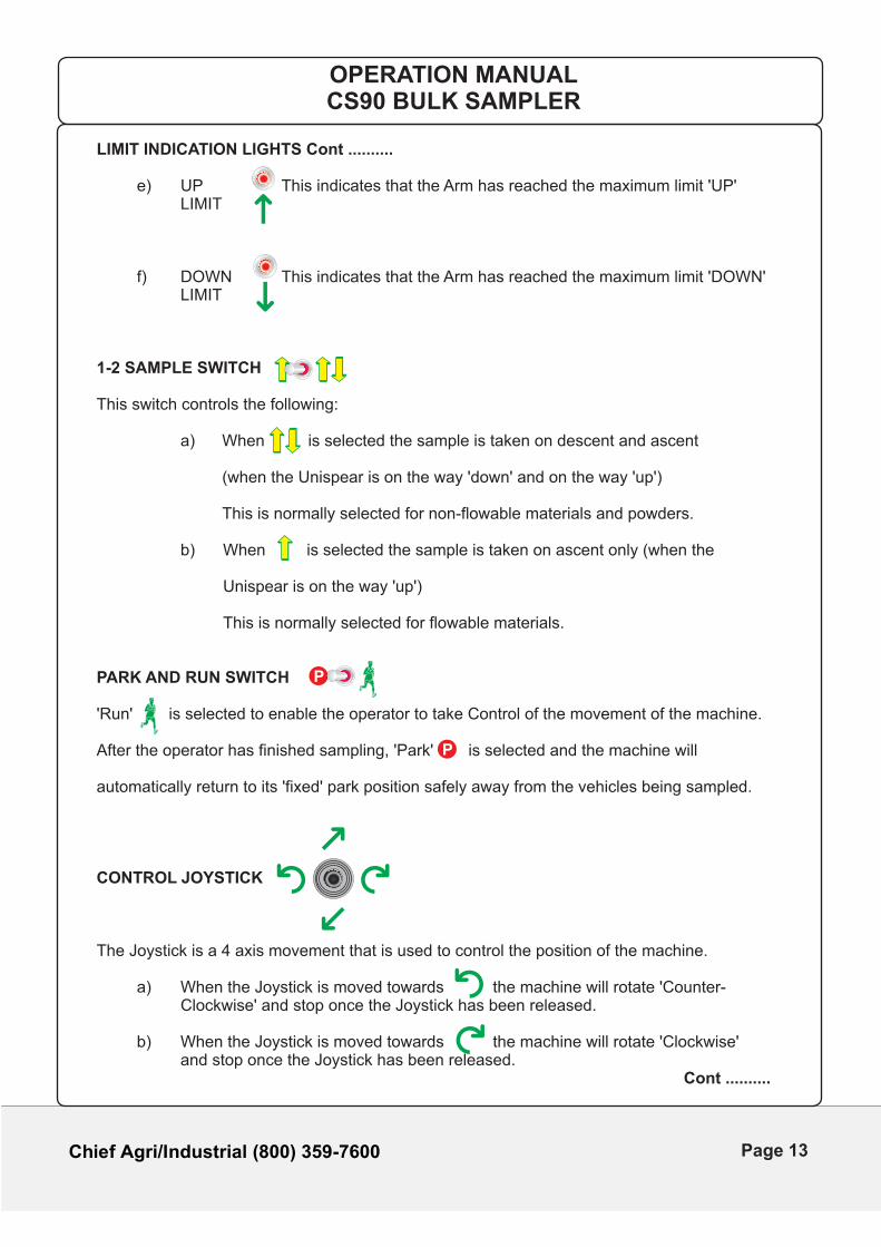
LIMIT INDICATION LIGHTS Cont ..........
e) UP This indicates that the Arm has reached the maximum limit 'UP' LIMIT
f) DOWN This indicates that the Arm has reached the maximum limit 'DOWN' LIMIT
1-2 SAMPLE SWITCH
This switch controls the following:
a) When is selected the sample is taken on descent and ascent
(when the Unispear is on the way 'down' and on the way 'up')
This is normally selected for non-flowable materials and powders.
b) When is selected the sample is taken on ascent only (when the
Unispear is on the way 'up')
This is normally selected for flowable materials.
PARK AND RUN SWITCH
'Run' is selected to enable the operator to take Control of the movement of the machine.
After the operator has finished sampling, 'Park' is selected and the machine will
automatically return to its 'fixed' park position safely away from the vehicles being sampled.
CONTROL JOYSTICK
The Joystick is a 4 axis movement that is used to control the position of the machine.
a) When the Joystick is moved towards the machine will rotate 'Counter- Clockwise' and stop once the Joystick has been released.
b) When the Joystick is moved towards the machine will rotate 'Clockwise' and stop once the Joystick has been released. Cont ..........
P
P
OPERATION MANUALCS90 BULK SAMPLER
Page 13
Chief Agri/Industrial (800) 359-7600
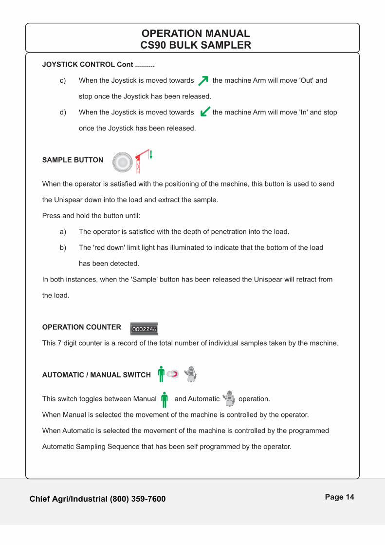
JOYSTICK CONTROL Cont ..........
c) When the Joystick is moved towards the machine Arm will move 'Out' and
stop once the Joystick has been released.
d) When the Joystick is moved towards the machine Arm will move 'In' and stop
once the Joystick has been released.
SAMPLE BUTTON
When the operator is satisfied with the positioning of the machine, this button is used to send
the Unispear down into the load and extract the sample.
Press and hold the button until:
a) The operator is satisfied with the depth of penetration into the load.
b) The 'red down' limit light has illuminated to indicate that the bottom of the load
has been detected.
In both instances, when the 'Sample' button has been released the Unispear will retract from
the load.
OPERATION COUNTER
This 7 digit counter is a record of the total number of individual samples taken by the machine.
AUTOMATIC / MANUAL SWITCH
This switch toggles between Manual and Automatic operation.
When Manual is selected the movement of the machine is controlled by the operator.
When Automatic is selected the movement of the machine is controlled by the programmed
Automatic Sampling Sequence that has been self programmed by the operator.
0002246
OPERATION MANUALCS90 BULK SAMPLER
Page 14
Chief Agri/Industrial (800) 359-7600
AUTO SAMPLE POINT SWITCH
When this feature is activated the machine will automatically extract samples from the load.
The operator has 4 options to use when self programming the sample positions.
This will allow between 1 and 15 positions in the load to be programmed forA automatic sampling.
This will allow 3 sample positions in the load to be programmed for automatic sampling.3
This will allow 5 sample positions in the load to be programmed for automatic sampling.5
This will allow 8 sample positions in the load to be programmed for automatic sampling.8
AUTO PROGRAM BUTTON
Press and hold this button while programming the Automatic Sampling Sequence. Once the
sequence has been programmed and the machine has returned to its park position (Arm has
moved 'In' and back 'Out') the button can be released. (Refer to Section 2 for Operating and
Programming)
AUTO START BUTTON
This button is pressed to 'Start' the Automatic Sampling Sequence.
A3 5 8
OPERATION MANUALCS90 BULK SAMPLER
Page 15
Chief Agri/Industrial (800) 359-7600
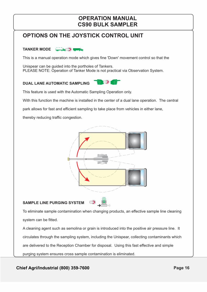
OPTIONS ON THE JOYSTICK CONTROL UNIT
TANKER MODE
This is a manual operation mode which gives fine 'Down' movement control so that the
Unispear can be guided into the portholes of Tankers.PLEASE NOTE: Operation of Tanker Mode is not practical via Observation System.
DUAL LANE AUTOMATIC SAMPLING
This feature is used with the Automatic Sampling Operation only.
With this function the machine is installed in the center of a dual lane operation. The central
park allows for fast and efficient sampling to take place from vehicles in either lane,
thereby reducing traffic congestion.
SAMPLE LINE PURGING SYSTEM
To eliminate sample contamination when changing products, an effective sample line cleaning
system can be fitted.
A cleaning agent such as semolina or grain is introduced into the positive air pressure line. It
circulates through the sampling system, including the Unispear, collecting contaminants which
are delivered to the Reception Chamber for disposal. Using this fast effective and simple
purging system ensures cross sample contamination is eliminated.
OPERATION MANUALCS90 BULK SAMPLER
Page 16

Chief Agri/Industrial (800) 359-7600
This Page Is Intentionally Left Blank
Page 17

Chief Agri/Industrial (800) 359-7600
CS90
SECTION 2
OPERATING THE
CONTROL UNIT
OPERATION MANUALCS90 BULK SAMPLER
Page 18
Chief Agri/Industrial (800) 359-7600
WARNING Prior to operating the equipment ensure that:
Only trained personnel operate the equipment.
The sampling area is clear of personnel and any obstructions.
The machine is in the correct starting position.
No persons enter the sampling area while the machine is in operation.
Check for any damage to the Machine Support Frame, Cables and Hoses.
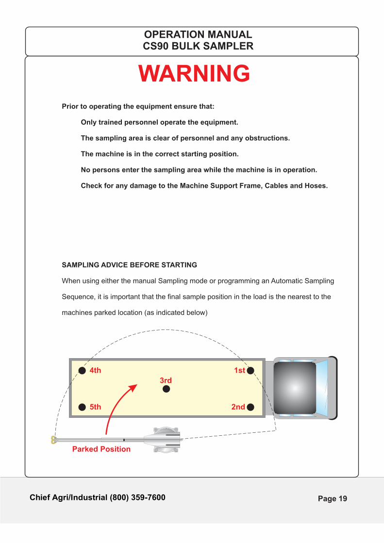
SAMPLING ADVICE BEFORE STARTING
When using either the manual Sampling mode or programming an Automatic Sampling Sequence, it is important that the final sample position in the load is the nearest to the machines parked location (as indicated below)
OPERATION MANUALCS90 BULK SAMPLER
1st4th
2nd
3rd
Parked Position
5th
Page 19
Chief Agri/Industrial (800) 359-7600
MANUAL SAMPLING OPERATION
1. Turn on the power at the Terminal Supply Box.
2. On the Control Unit ensure that the 'Automatic / Manual' operation switch is switched on to 'Manual'
3. Move the 'Park / Run' switch to 'Run'
4. Position the Arm to the desired location for sampling by using the Control Joystick.
5. Assess the material to be sampled for flowability.
Adjust the '1-2 Sample' switch as follows:
a) For non-flowable materials and powders select
This means that the sample is taken on descent and ascent.
b) For flowable materials select
This means that the sample is taken on ascent only.
6. Press and hold the 'Sample' button until the 'red down' light
is illuminated.
Release the button and the Arm will automatically withdraw from the load, simultaneously transferring the sample to the Reception Chamber.
Note : When the Arm is fully extended and entering the load, the Arm will flex.
This is expected within the machines working parameters.
7. Having collected the required sample, set the 'Park / Run' switch to 'Park'
and the machine will automatically return to the park position.
P
PP
OPERATION MANUALCS90 BULK SAMPLER
Page 20
Chief Agri/Industrial (800) 359-7600
AUTOMATIC SAMPLING OPERATION
Prior to the use of Automatic Sampling the operator must self program a sampling sequence with up to 15 positions in the load.
SELF PROGRAMMING SEQUENCE
1. Ensure that the 'Park / Run switch' is set to 'Park'
If the Control Unit is fitted with the optional 'Tanker' Mode
ensure that the switch is set to the 'Trailer' position
If the Control Unit is fitted with the optional 'Dual Lane' Mode
ensure that the switch is set to the correct lane for sampling.
2. Set the 'Manual / Automatic' switch to 'Automatic'
3. Set the 'Auto Sample Point' switch to the desired number of samples required
as follows:
This will allow between 1 and 15 positions in the load to be programmed forA automatic sampling.
This will allow 3 positions in the load to be programmed for automatic sampling.3
This will allow 5 positions in the load to be programmed for automatic sampling.5
This will allow 8 positions in the load to be programmed for automatic sampling.8
4. Assess the material to be sampled for flowability.
Adjust the '1-2 Sample' switch as follows:
a) For non-flowable materials and powders select
This means that the sample is taken on descent and ascent.
b) For flowable materials select
This means that the sample is taken on ascent only.
5. Set the 'Park / Run' switch to 'Run'
6. The 'Auto Program' button must be pressed and held until the programming sequence has been completed.
PP
A3 5 8
P
OPERATION MANUALCS90 BULK SAMPLER
Page 21
Chief Agri/Industrial (800) 359-7600
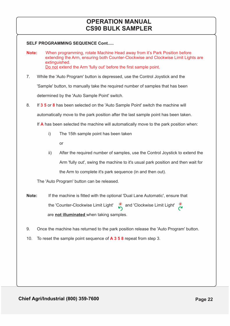
SELF PROGRAMMING SEQUENCE Cont.....
Note: When programming, rotate Machine Head away from it’s Park Position before extending the Arm, ensuring both Counter-Clockwise and Clockwise Limit Lights are extinguished. Do not extend the Arm 'fully out' before the first sample point.
7. While the 'Auto Program' button is depressed, use the Control Joystick and the
'Sample' button, to manually take the required number of samples that has been
determined by the 'Auto Sample Point' switch.
8. If or has been selected on the 'Auto Sample Point' switch the machine will3 5 8
automatically move to the park position after the last sample point has been taken.
If has been selected the machine will automatically move to the park position when:A
i) The 15th sample point has been taken
or
ii) After the required number of samples, use the Control Joystick to extend the
Arm 'fully out', swing the machine to it's usual park position and then wait for
the Arm to complete it's park sequence (in and then out).
The 'Auto Program' button can be released.
Note: If the machine is fitted with the optional 'Dual Lane Automatic', ensure that
the 'Counter-Clockwise Limit Light' and 'Clockwise Limit Light'
are not illuminated when taking samples.
9. Once the machine has returned to the park position release the 'Auto Program' button.
10. To reset the sample point sequence of repeat from step 3.A 3 5 8
OPERATION MANUALCS90 BULK SAMPLER
Page 22
Chief Agri/Industrial (800) 359-7600
AUTOMATIC SAMPLING OPERATION
OPERATING IN THE AUTOMATIC SAMPLING MODE
1. Ensure that the 'Park / Run switch' is set to 'Park'
2. If the Control Unit is fitted with the optional 'Tanker' Mode
ensure that the switch is set to the 'Trailer' position
3. If the Control Unit is fitted with the optional 'Dual Lane' Mode
ensure that the switch is set to the correct lane for sampling.
4. Set the 'Manual / Automatic' switch to 'Automatic'
5. Set the 'Auto Sample Point' switch to the desired number of samples required
6. Assess the material to be sampled for flowability.
Adjust the '1-2 Sample' Switch as follows:
a) For non-flowable materials and powders select
This means that the sample is taken on descent and ascent.
b) For flowable materials select
This means that the sample is taken on ascent only.
7. Set the 'Park / Run' switch to 'Run' and then back to 'Park'
8. Press the 'Auto Start' button
The machine will begin to sample as determined by the selected pre-programmed
sequence. The machine will return to the park position after the last sample has
been taken and the sample will be transported to the Reception Chamber.
PP
A3 5 8
P P
OPERATION MANUALCS90 BULK SAMPLER
Page 23
Chief Agri/Industrial (800) 359-7600
STOPPING THE MACHINE WHILE IN AUTOMATIC SAMPLING MODE
If for any reason the machine needs to be stopped during an automatic sampling sequence
proceed as follows:
1. While the machine is running set the 'Park / Run switch' to 'Run'
If the machine was entering the load when the operator activated 'Run' then the
Unispear will retract from the load, the Arm will move to the 'Up' position and stop.
2. Move the 'Manual / Automatic' switch to 'Manual'
At this point Manual operation may be used to complete the taking of samples.
3. When finished set the 'Park / Run switch' to 'Park'
P
PP
OPERATION MANUALCS90 BULK SAMPLER
Page 24
Chief Agri/Industrial (800) 359-7600
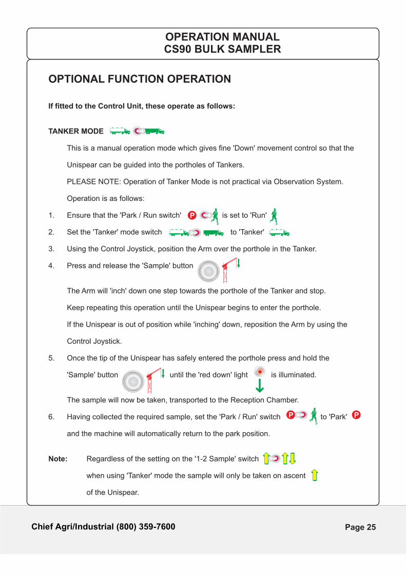
OPTIONAL FUNCTION OPERATION
If fitted to the Control Unit, these operate as follows:
TANKER MODE
This is a manual operation mode which gives fine 'Down' movement control so that the Unispear can be guided into the portholes of Tankers. PLEASE NOTE: Operation of Tanker Mode is not practical via Observation System.
Operation is as follows:
1. Ensure that the 'Park / Run switch' is set to 'Run'
2. Set the 'Tanker' mode switch to 'Tanker'
3. Using the Control Joystick, position the Arm over the porthole in the Tanker.
4. Press and release the 'Sample' button
The Arm will 'inch' down one step towards the porthole of the Tanker and stop.
Keep repeating this operation until the Unispear begins to enter the porthole.
If the Unispear is out of position while 'inching' down, reposition the Arm by using the
Control Joystick.
5. Once the tip of the Unispear has safely entered the porthole press and hold the
'Sample' button until the 'red down' light is illuminated.
The sample will now be taken, transported to the Reception Chamber.
6. Having collected the required sample, set the 'Park / Run' switch to 'Park'
and the machine will automatically return to the park position.
Note: Regardless of the setting on the '1-2 Sample' switch
when using 'Tanker' mode the sample will only be taken on ascent
of the Unispear.
P
PP
OPERATION MANUALCS90 BULK SAMPLER
Page 25
Chief Agri/Industrial (800) 359-7600
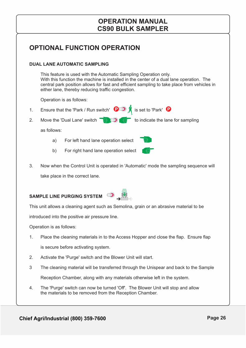
OPTIONAL FUNCTION OPERATION
DUAL LANE AUTOMATIC SAMPLING
This feature is used with the Automatic Sampling Operation only. With this function the machine is installed in the center of a dual lane operation. The central park position allows for fast and efficient sampling to take place from vehicles in either lane, thereby reducing traffic congestion.
Operation is as follows:
1. Ensure that the 'Park / Run switch' is set to 'Park'
2. Move the 'Dual Lane' switch to indicate the lane for sampling
as follows:
a) For left hand lane operation select
b) For right hand lane operation select
3. Now when the Control Unit is operated in 'Automatic' mode the sampling sequence will
take place in the correct lane.
SAMPLE LINE PURGING SYSTEM
This unit allows a cleaning agent such as Semolina, grain or an abrasive material to be
introduced into the positive air pressure line.
Operation is as follows:
1. Place the cleaning materials in to the Access Hopper and close the flap. Ensure flap
is secure before activating system.
2. Activate the 'Purge' switch and the Blower Unit will start.
3 The cleaning material will be transferred through the Unispear and back to the Sample
Reception Chamber, along with any materials otherwise left in the system.
4. The 'Purge' switch can now be turned 'Off'. The Blower Unit will stop and allow the materials to be removed from the Reception Chamber.
PP
OPERATION MANUALCS90 BULK SAMPLER
Page 26
Chief Agri/Industrial (800) 359-7600
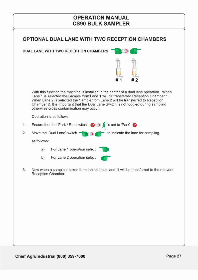
OPTIONAL DUAL LANE WITH TWO RECEPTION CHAMBERS
DUAL LANE WITH TWO RECEPTION CHAMBERS
With this function the machine is installed in the center of a dual lane operation. When Lane 1 is selected the Sample from Lane 1 will be transferred Reception Chamber 1. When Lane 2 is selected the Sample from Lane 2 will be transferred to Reception Chamber 2. It is important that the Dual Lane Switch is not toggled during sampling otherwise cross contamination may occur.
Operation is as follows:
1. Ensure that the 'Park / Run switch' is set to 'Park'
2. Move the 'Dual Lane' switch to indicate the lane for sampling
as follows:
a) For Lane 1 operation select
b) For Lane 2 operation select
3. Now when a sample is taken from the selected lane, it will be transferred to the relevant Reception Chamber.
OPERATION MANUALCS90 BULK SAMPLER
# 1 # 2
MAX LEVEL MAX LEVEL
PP
Page 27
Chief Agri/Industrial (800) 359-7600
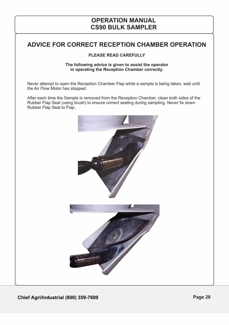
ADVICE FOR CORRECT RECEPTION CHAMBER OPERATION
PLEASE READ CAREFULLY
The following advice is given to assist the operator in operating the Reception Chamber correctly.
Never attempt to open the Reception Chamber Flap while a sample is being taken, wait until the Air Flow Motor has stopped.
After each time the Sample is removed from the Reception Chamber, clean both sides of the Rubber Flap Seal (using brush) to ensure correct sealing during sampling. Never fix down Rubber Flap Seal to Flap.
OPERATION MANUALCS90 BULK SAMPLER
Page 28
Chief Agri/Industrial (800) 359-7600
ADVICE FOR FAST EFFICIENT OPERATION
PLEASE READ CAREFULLY
The following advice is given to assist the operator in minimising both sampling time and machine wear.
1. Ensure the Arm is at least a quarter extended before rotating over the side of standard
trailers. If the trailer has an extension side, the Arm should be fully extended before
rotating over the side of the trailer.
2. Watch out for any obstacles in the trailer, ie catwalks, baffle plates, tie chains etc.
Aim to sample at least 1’ away from any obstructions. If an obstacle is struck by
the Unispear, immediately release the 'Sample' button.
3. To avoid damage to the bottom of small trailers containing a shallow depth of material,
release the 'Sample' button as soon as the Unispear stops descending.
4. Should any sample remain in the transfer hose when sampling the line can be cleared
as follows:
i) Ensure the sampling area is clear of personnel and any obstructions.
ii) Press the 'Sample' button to take the Arm down past its horizontal position
and then release the 'Sample' button.
This will activate the Air Flow System and clear the line.
5. Avoid over filling the Sample Reception Chamber beyond the maximum level
indicator, to prevent damage to the Air Flow System.
6. At the end of the sampling day, ensure that the 'Park / Run' switch
is set to 'Park' with the main electricity supply left 'ON'.
7. If for any reason it is necessary to turn the main electric supply 'OFF', always press
the red 'STOP' button on the Terminal Supply Box.
DO NOT turn off the Isolator Switch on the Terminal Supply Box, as this will cause the
pre-set park position to be lost.
P
P
OPERATION MANUALCS90 BULK SAMPLER
Page 29
Chief Agri/Industrial (800) 359-7600
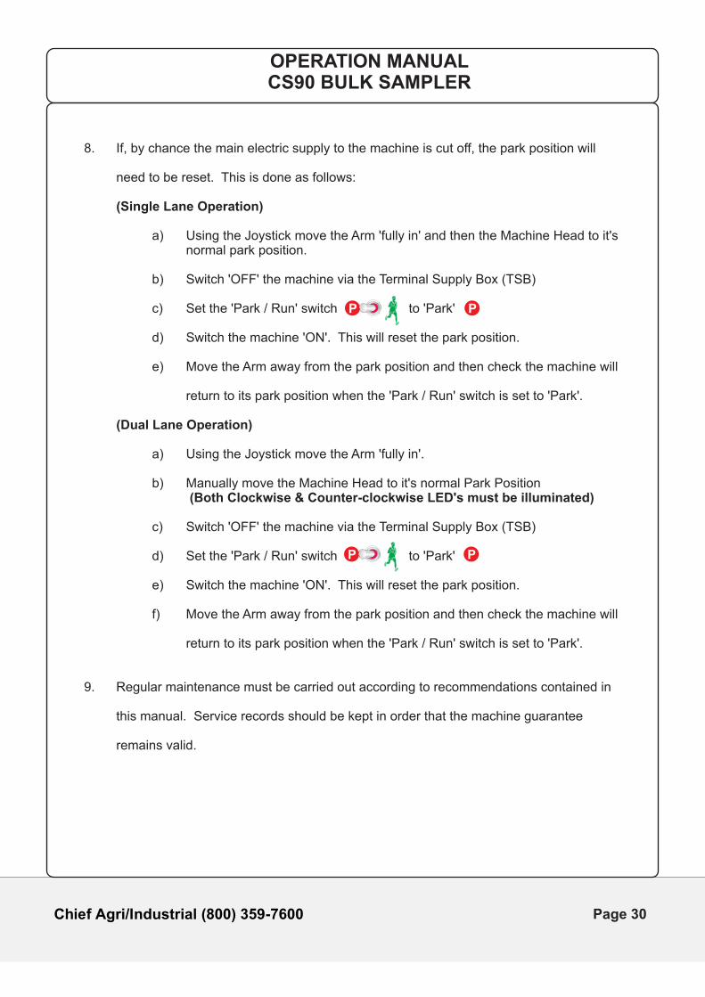
8. If, by chance the main electric supply to the machine is cut off, the park position will
need to be reset. This is done as follows:
(Single Lane Operation)
a) Using the Joystick move the Arm 'fully in' and then the Machine Head to it's normal park position.
b) Switch 'OFF' the machine via the Terminal Supply Box (TSB)
c) Set the 'Park / Run' switch to 'Park'
d) Switch the machine 'ON'. This will reset the park position.
e) Move the Arm away from the park position and then check the machine will
return to its park position when the 'Park / Run' switch is set to 'Park'.
(Dual Lane Operation)
a) Using the Joystick move the Arm 'fully in'.
b) Manually move the Machine Head to it's normal Park Position (Both Clockwise & Counter-clockwise LED's must be illuminated)
c) Switch 'OFF' the machine via the Terminal Supply Box (TSB)
d) Set the 'Park / Run' switch to 'Park'
e) Switch the machine 'ON'. This will reset the park position.
f) Move the Arm away from the park position and then check the machine will
return to its park position when the 'Park / Run' switch is set to 'Park'.
9. Regular maintenance must be carried out according to recommendations contained in
this manual. Service records should be kept in order that the machine guarantee
remains valid.
PP
OPERATION MANUALCS90 BULK SAMPLER
PP
Page 30
OPERATION MANUALCS90 BULK SAMPLER
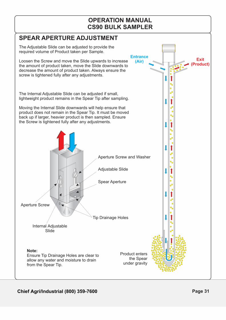
SPEAR APERTURE ADJUSTMENT
Note:Ensure Tip Drainage Holes are clear to allow any water and moisture to drain from the Spear Tip.
Spear Aperture
Adjustable Slide
Aperture Screw and Washer
Aperture Screw
Internal AdjustableSlide
Tip Drainage Holes
Exit(Product)
Entrance(Air)
Product entersthe Spear
under gravity
The Adjustable Slide can be adjusted to provide the required volume of Product taken per Sample.
Loosen the Screw and move the Slide upwards to increase the amount of product taken, move the Slide downwards to decrease the amount of product taken. Always ensure the screw is tightened fully after any adjustments.
The Internal Adjustable Slide can be adjusted if small, lightweight product remains in the Spear Tip after sampling.
Moving the Internal Slide downwards will help ensure that product does not remain in the Spear Tip. It must be moved back up if larger, heavier product is then sampled. Ensure the Screw is tightened fully after any adjustments.
Chief Agri/Industrial (800) 359-7600
Page 31

This Page Is Intentionally Left Blank
Chief Agri/Industrial (800) 359-7600
Page 32
Chief Agri/Industrial (800) 359-7600
CS90CS90
SECTION 3
MAINTENANCE
OPERATION MANUALCS90 BULK SAMPLER
Page 33
Chief Agri/Industrial (800) 359-7600
MAINTENANCE
WARNING
Maintenance must only be carried out by suitably trained personnel.
Ensure that all guards are re-fitted securely after any work has been completed.
Whenever maintenance work is carried out, the main electric supply to the machine
must be isolated.
Refer to the Operations Counter on the Control Unit to assess type of service required
FIRST SERVICE (At 6000 operations)
1. Check all nuts, bolts and setscrews for tightness.
2. Check all proximity switches for correct distances.
a) Swivel Proximity Switch
This should be set at 3/16” between the stop and the switch.
b) Pressure Down Proximity Switch
This should be set at 1/16” above and below the actuator block on the
spring plate.
c) Rack Plate Proximity Switches
These should be set at 1/16” clearance from the rack stops.
3. Continue with the standard 6000 operation service check on components shown on
following pages.
4. All surfaces of Guards, Motor Cases, Electrical Boxes and general horizontal surfaces,
including inside the Air Flow Motor Housing, should be cleaned to ensure dust deposits
do not cause ingress damage or potential overheating.
OPERATION MANUALCS90 BULK SAMPLER
Page 34
Chief Agri/Industrial (800) 359-7600
'A'
'C'
'V'
'B'
'PDL''PD'
'R'
'L'
'B'
'SP'
'D'
'S'
'W'
'B'
'RP1'
'RPL'
'RP2'
'AP2''AP1'
'G'
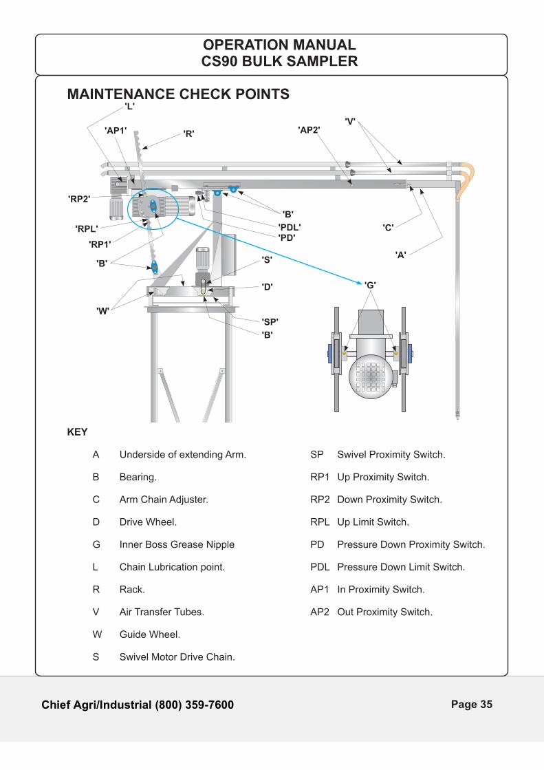
MAINTENANCE CHECK POINTS
KEY
A Underside of extending Arm. SP Swivel Proximity Switch.
B Bearing. RP1 Up Proximity Switch.
C Arm Chain Adjuster. RP2 Down Proximity Switch.
D Drive Wheel. RPL Up Limit Switch.
G Inner Boss Grease Nipple PD Pressure Down Proximity Switch.
L Chain Lubrication point. PDL Pressure Down Limit Switch. R Rack. AP1 In Proximity Switch.
V Air Transfer Tubes. AP2 Out Proximity Switch. W Guide Wheel. S Swivel Motor Drive Chain.
OPERATION MANUALCS90 BULK SAMPLER
Page 35
Chief Agri/Industrial (800) 359-7600
EVERY 6 MONTHS OR 6000 OPERATIONS(Whichever is soonest)
1. With the Arm fully extended, grease the underside of the Arm 'A' using a 'Food Safe'
Grease.
2. Grease the Arm Chain 'L' using a 'Food Safe' Grease.
3. Grease both Racks 'R' using a 'Food Safe' Grease.
4. Check the Arm Chain tension. There should be no more than 3/16” movement when the
chain is pulled together at point 'L'. If necessary slacken off the M10 nut on the side of
the Chain Adjuster 'C'. Tighten the M12 Nut on the end of the Chain Adjuster to increase
the tension. Re-tighten the M10 Nut on the side of the Chain Adjuster.
5. Check the Swivel Motor Drive Chain tension 'S'. There should be no more than 3/16”
movement when the chain is pulled together at it mid point. The Chain tension can be
adjusted by lowering or raising the Swivel Motor mounting plate.
Grease the Chain with a 'Food Safe' Grease.
6. Check all Motor/Gearbox assemblies for wear or signs of leaking seals. Any leaking seals
should be replaced to prevent damage to the Gearbox components.
7. Check the condition of all cable glands entering Electrical Enclosures, Limit and Proximity
Switches, Internal / External Control Units and Air Flow Motor Housing for damage or
water / dust ingress. Replace any components where damage is evident or failure is
possible before the next service interval.
8. Inspect condition of flexible Transfer Hoses for damage, particularly where equipment is
exposed to cold ( (0°F) or heat 100°F). Replace any damaged Transfer Hoses using
recommended Chief product.
9. All surfaces of Guards, Motor Cases, Electrical Boxes and general horizontal surfaces,
including inside the Air Flow Motor Housing, should be cleaned to ensure dust deposits do not cause ingress damage or potential overheating.
10. Check grounding system for integrity.
OPERATION MANUALCS90 BULK SAMPLER
Page 36
Chief Agri/Industrial (800) 359-7600
ANNUALLY OR 12000 OPERATIONS
Include the 6 Month Maintenance.
1. Lubricate all Bearings 'B' grease with a 'Food Safe' Grease.
2. Grease Inner Boss 'G' with a 'Food Safe' Grease.
3. It is recommended that when the machine is to be idle for 2 to 6 months, the
6 month maintenance should be carried out on 'Shut down' and again prior to
'Start up'.
Similarly, after the machine has been idle for more than 6 months, the annual service
is recommended prior to 'Start up'.
4. Keep the Drive Wheel 'D' free from grease, ice and debris especially in the Winter, to
prevent any slippage.
5. Whenever any maintenance on the machine is carried out, complete the machine service
record sheet.
OPERATION MANUALCS90 BULK SAMPLER
Page 37

This Page Is Intentionally Left Blank
Chief Agri/Industrial (800) 359-7600
Page 38
Chief Agri/Industrial (800) 359-7600
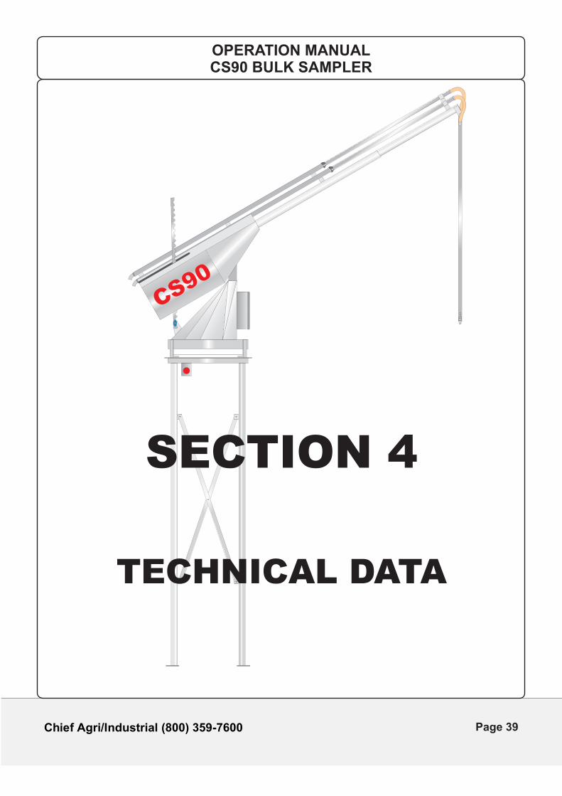
CS90
SECTION 4
TECHNICAL DATA
OPERATION MANUALCS90 BULK SAMPLER
Page 39
Chief Agri/Industrial (800) 359-7600
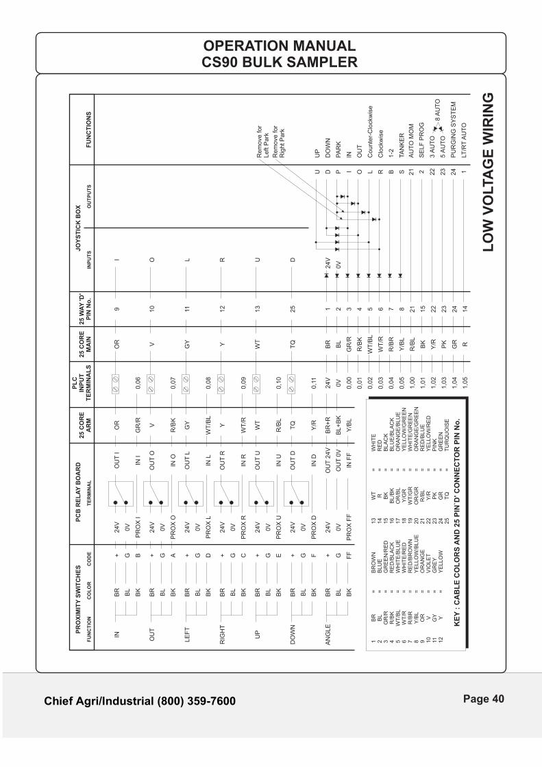
PR
OX
IMIT
Y S
WIT
CH
ES
FU
NC
TIO
NC
OL
OR
INP
UT
SC
OD
EO
UT
PU
TS
TE
RM
INA
L
IN
OU
T
LE
FT
RIG
HT
UP
DO
WN
AN
GLE
BR
24V
24V
24V
24V
24V
24V
24V
0V
0V
0V
0V
0V
0V
PR
OX
O
PR
OX
L
PR
OX
R
PR
OX
U
PR
OX
D
PR
OX
FF
OU
T I
OU
T O
OU
T L
OU
T R
OU
T U
OU
T D
OU
T 0
V
IN O
IN L
IN R
IN U
OU
T 2
4V
IN D
IN F
F
OR
GR
/R
V
R/B
K
GY
WT
/BL
WT
/R
WT
R/B
L
TQ
Y/R
BR
+R
BL
+B
K
Y/B
L
Y
0,0
6
0,0
7
0,0
8
0,0
9
0,1
0
0,1
1
24V
0V
0,0
0
0,0
1
0,0
2
0,0
3
0,0
4
0,0
5
1,0
0
1,0
1
1,0
2
1,0
3
1,0
4
1,0
5
OR V GY Y WT
TQ
BR
BL
GR
/R
R/B
K
WT
/BL
WT
/R
R/B
R
Y/B
L
R/B
L
BK
Y/R
PK
GR R
9 10
11 12
13
25 1
24V
0V
2 3 4 5 6 7 8 21
15
22
23
24
14
2 124
23
22
21SBRLOIPDU
UP
Rem
ove for
Rig
ht P
ark
Rem
ove for
Left P
ark
DO
WN
PA
RK
IN OU
T
Counte
r-C
lockw
ise
Clo
ckw
ise
1-2
TA
NK
ER
AU
TO
MO
M
3 A
UT
O8 A
UT
O5 A
UT
O
PU
RG
ING
SY
ST
EM
LT/R
T A
UT
O
SE
LF
PR
OG
I O L R U D
BL
0V
BK
PR
OX
IIN
I
BR
BL
BK
BR
BL
BK
BR
BL
BK
BR
BL
BK
BR
BL
BK
BR
BL
BK
+ G A + G D + G C + G E + G F + G FF
PC
B R
EL
AY
BO
AR
D25 C
OR
EA
RM
PL
CIN
PU
TT
ER
MIN
AL
S25 C
OR
EM
AIN
25 W
AY
'D
'P
IN N
o.
JO
YS
TIC
K B
OX
FU
NC
TIO
NS
+ G B
LO
W V
OLTA
GE
WIR
ING
1
BR
=
B
RO
WN
2
BL
=
B
LU
E3
GR
/R
=
GR
EE
N/R
ED
4
R/B
K
=
RE
D/B
LA
CK
5
WT
/BL
=
W
HIT
E/B
LU
E6
WT
/R
=
WH
ITE
/RE
D7
R/B
R
=
RE
D/B
RO
WN
8
Y/B
L
=
YE
LLO
W/B
LU
E9
OR
=
O
RA
NG
E10
V
=
VIO
LE
T11
G
Y
=
GR
EY
12
Y
=
YE
LLO
W
KE
Y :
CA
BL
E C
OL
OR
S A
ND
25 P
IN`D
' C
ON
NE
CT
OR
PIN
No
.
13
WT
=
W
HIT
E14
R
=
RE
D15
BK
=
B
LA
CK
16
BL
/BK
=
B
LU
E/B
LA
CK
17
OR
/BL
=
O
RA
NG
E/B
LU
E18
Y/G
R
=
YE
LLO
W/G
RE
EN
19
WT
/GR
=
W
HIT
E/G
RE
EN
20
OR
/GR
=
O
RA
NG
E/G
RE
EN
21
R/B
L
=
RE
D/B
LU
E22
Y/R
=
Y
ELLO
W/R
ED
23
PK
=
P
INK
24
GR
=
G
RE
EN
25
TQ
=
T
UR
QU
OIS
E
OPERATION MANUALCS90 BULK SAMPLER
Page 40
Chief Agri/Industrial (800) 359-7600
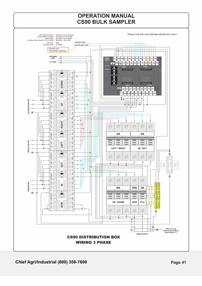
OPERATION MANUALCS90 BULK SAMPLER
I0
AF
M
A1
13
5L
1L
2L
3
A2
24
6T
1T
2T
3
II
00
INO
UT
13
521
21
A1
L1
L2
L3
NC
NC
13
521
A1
L1
L2
L3
NC
24
622
22
A2
T1
T2
T3
24
622
A2
T1
T2
T3
II
00
LE
FT
RIG
HT
24
622
A2
T1
T2
T3
24
622
A2
T1
T2
T3
13
521
A1
L1
L2
L3
NC
13
521
A1
L1
L2
L3
NC
II
00
UP
DO
WN
13
521
A1
L1
L2
L3
NC
13
521
A1
L1
L2
L3
NC
24
622
A2
T1
T2
T3
24
622
A2
T1
T2
T3
EXP
L1 L2N COM 01 03 05 07 09 11 01 03 05
NC040200100806040200
0CH 1CH
IN
COMCOMCOMCOMCOM
10CH 11CH
+
-
00 01 02 04
03
05 07
06
00 02
01 03
OUT
POWER
RUN
ERR/ALM
INH
PRPHL
BKUP
PERIPHERAL
BATTERY
OMRONSYSMACCP1E
ON
10A
AFM
ON
2A
PLC
ONONON
UP / DOWN
6A
ONONON
LEFT / RIGHT
2A
ONONON
IN / OUT
2A
16
16 18
1A 1B 1C
1A 1B 1C
MAINS SUPPLY
Cable 10’ long wired as part of Assy
(strip sheath 1’)
EL
EV
AT
ION
MO
TO
R
UP LIMIT
UP/DOWNLIMIT
SW
IVE
L M
OT
OR
AR
M M
OT
OR
2
2
17
17
2 2
13
14
15
8
4
9
5
10
6
13
14
15
8
4
9
5
10
6
050
060
050
060
05
06
05 06
113112111
113
112
111
7373
33
72
72
32
71 333231
71
31
18
CONTROL MULTICORE
ARM MULTICORE
Please note that colors do not indicate wire colors
2
03
03
04
04
01
01
02
02
07
07
CS90 DISTRIBUTION BOX
WIRING 3 PHASE
Bootlace 0.5 mm OrangeBootlace 0.5 mm WhiteBootlace 1.5 mm BlackBootlace 1.0mm Red
Arm Multicore Wires -Control Multicore Wires -
Earth Wires -All other Wires (except 1.0 mm Solid) -
Link wires - SolidAll other wires - Tri Rated
1A
Page 41
Chief Agri/Industrial (800) 359-7600
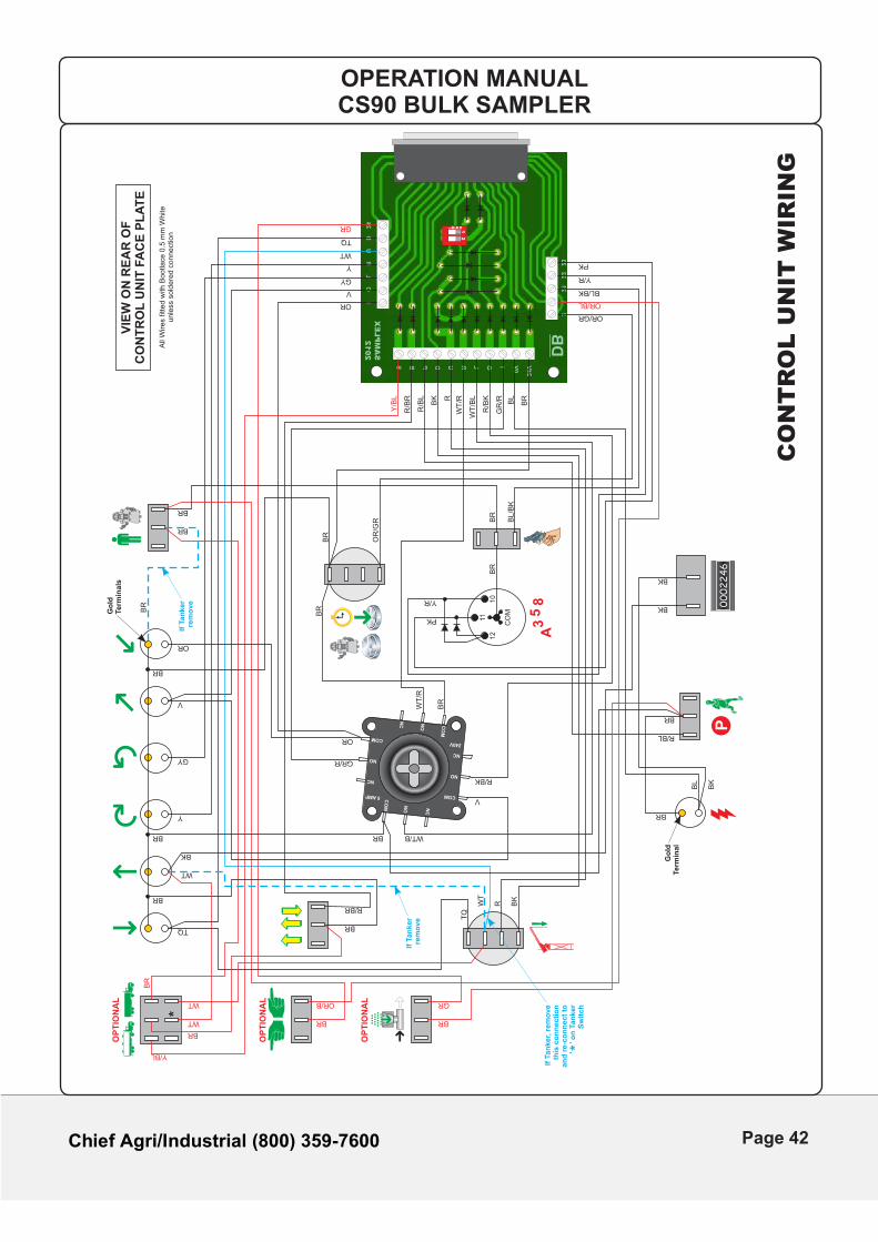
OPERATION MANUALCS90 BULK SAMPLER
CO
NT
RO
L U
NIT
WIR
ING
SAMPLEX
2012
I
S B P D U R
2
1
21
22
23
L O I0V
24V
DB
O
L
R
U
D
24 O
12
N
Page 42

Chief Agri/Industrial (800) 359-7600
This Page Is Intentionally Left Blank
Page 43

Chief Agri/Industrial (800) 359-7600
CS90
SECTION 5
TROUBLE SHOOTING
OPERATION MANUALCS90 BULK SAMPLER
Page 44
Chief Agri/Industrial (800) 359-7600
TROUBLE SHOOTING
If the sampling system appears to be malfunctioning use the following guide to identify theproblem and hopefully overcome it. If the symptom continues complete the fault diagnosisreport and fax or mail it to Chief Industries, Inc.
PROBLEM SOLUTION
Arm not going up Turn the mains off to remove the Unispear, then turn back on.
Check MCB 6A has not tripped. Check MCB 10A (AFM) has not tripped.
Check mains electricity supply has not tripped.
Check manual override switches on Racks and Spring plates.
Ensure 'Up' proximity switch is not activated.
Arm not going down Ensure the machine is in 'Run' and not 'Park'.
Check MCB 6A has not tripped. Check MCB 10A (AFM) has not tripped.
Check mains electricity supply has not tripped.
Check manual override switches on Racks.
Ensure 'Down' proximity switch is not activated.
Left / Right Swivel Ensure the machine is in 'Run' and not 'Park'.not functioning Check MCB 2A has not tripped. Check mains electricity supply has not tripped.
Check Drive Wheel for wear and obstacles.
Check mounting bolts on Guide Wheels are secure.
Check all Guide Bearings are present and complete.
Check Left / Right proximity switches are not activated when trying to move Left or Right.
OPERATION MANUALCS90 BULK SAMPLER
Page 45
Chief Agri/Industrial (800) 359-7600
PROBLEM SOLUTION
In / Out not functioning Ensure the machine is in 'Run' and not 'Park'.
Check mains electricity supply has not tripped.
Check MCB 2A has not tripped.
Check Chain location bolts on Arm.
Check In / Out proximity switches are not activated when trying to move In / Out.
Arm extended past limit Proximity switch has malfunctioned.
Not extracting sample Check Unispear for blockages.
Check hose for blockages and holes.
Check Sample Reception Chamber seals.
Examine Air Flow Motor System.
Arm may not have gone past its horizontal point.
Water in sample Check seals on the sliding Air Transfer Tubes.
Ensure drain holes in tip of spear are not blocked.
Automatic not operating Switches not in correct position.
Lost park position.
Temporary loss of mains electricity supply, reprogram sampling sequence.
Machine unable to park Using the Joystick move the Arm 'fully in' and then the (Single Lane) Machine Head to it's normal park position. Switch 'OFF' the machine via the Terminal Supply Box. Switch the 'Park / Run' switch to the 'Park' position. Switch the machine 'ON'. This will set the park position.
OPERATION MANUALCS90 BULK SAMPLER
Page 46
Chief Agri/Industrial (800) 359-7600
PROBLEM SOLUTION
Machine unable to park Using the Joystick move the Arm 'fully in'.(Dual Lane) Manually move the Machine Head to it's normal Park Position (Both Left & Right LED's must be illuminated) Switch 'OFF' the machine via Terminal Supply Box. Switch the 'Park / Run' switch to the 'Park' position. Switch the machine 'ON'. This will set the park position.
Diverter Valve Check Air Supply to Solenoid Valve.not working Check MCB in Valve Enclosure has not tripped. Check Signal Cable is plugged into Joystick Control Unit. Check for blockages in system. Check for movement of the Vane within the Diverter Valve by watching the indicator located on the front of the unit.
OPERATION MANUALCS90 BULK SAMPLER
Page 47

Chief Agri/Industrial (800) 359-7600
This Page Is Intentionally Left Blank
Page 48
Chief Agri/Industrial (800) 359-7600
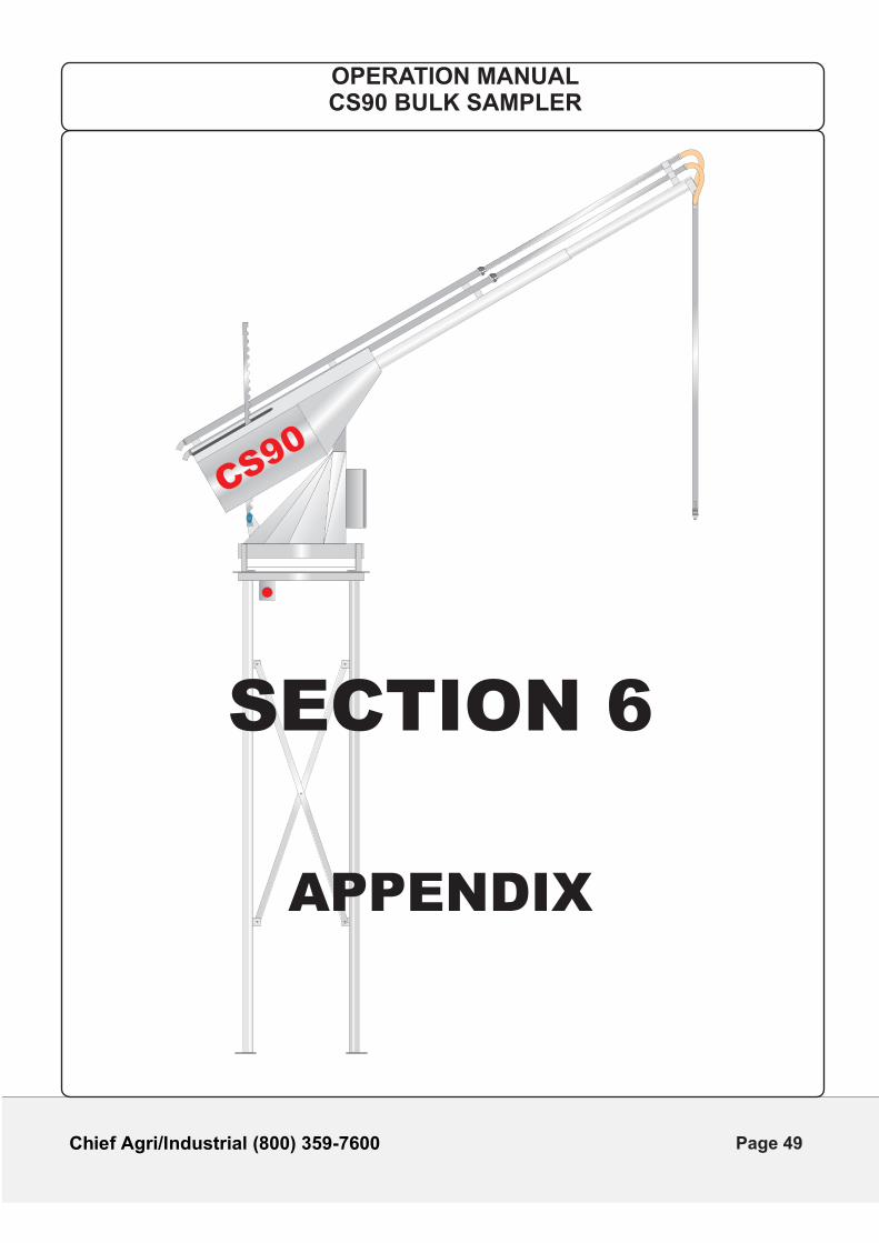
CS90
SECTION 6
APPENDIX
OPERATION MANUALCS90 BULK SAMPLER
Page 49
Chief Agri/Industrial (800) 359-7600
SE
RV
ICE
RE
CO
RD
SH
EE
T
DA
TE
INT
ER
IMS
ER
VIC
EF
UL
LS
ER
VIC
EO
TH
ER
RE
PA
IRS
# O
FO
PS
SIG
NE
DB
Y
OPERATION MANUALCS90 BULK SAMPLER
Page 50
Chief Agri/Industrial (800) 359-7600
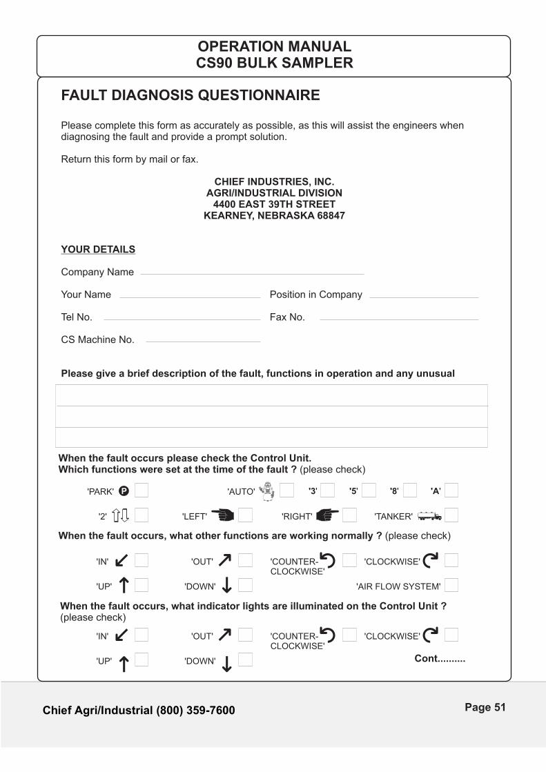
FAULT DIAGNOSIS QUESTIONNAIRE
Please complete this form as accurately as possible, as this will assist the engineers whendiagnosing the fault and provide a prompt solution.
Return this form by mail or fax.
CHIEF INDUSTRIES, INC. AGRI/INDUSTRIAL DIVISION
4400 EAST 39TH STREETKEARNEY, NEBRASKA 68847
YOUR DETAILS
Company Name
Your Name Position in Company
Tel No. Fax No.
CS Machine No.
Please give a brief description of the fault, functions in operation and any unusual
When the fault occurs, what other functions are working normally ? (please check)
When the fault occurs, what indicator lights are illuminated on the Control Unit ?(please check)
When the fault occurs please check the Control Unit.Which functions were set at the time of the fault ? (please check)
P'PARK'
'2' 'LEFT'
'OUT'
'OUT'
'IN'
'IN'
'DOWN'
'DOWN'
'UP'
'UP'
'RIGHT' 'TANKER'
'AUTO' '3' '5' '8' 'A'
OPERATION MANUALCS90 BULK SAMPLER
'COUNTER-CLOCKWISE'
'AIR FLOW SYSTEM'
'CLOCKWISE'
Cont..........
'COUNTER-CLOCKWISE'
'CLOCKWISE'
Page 51
Chief Agri/Industrial (800) 359-7600
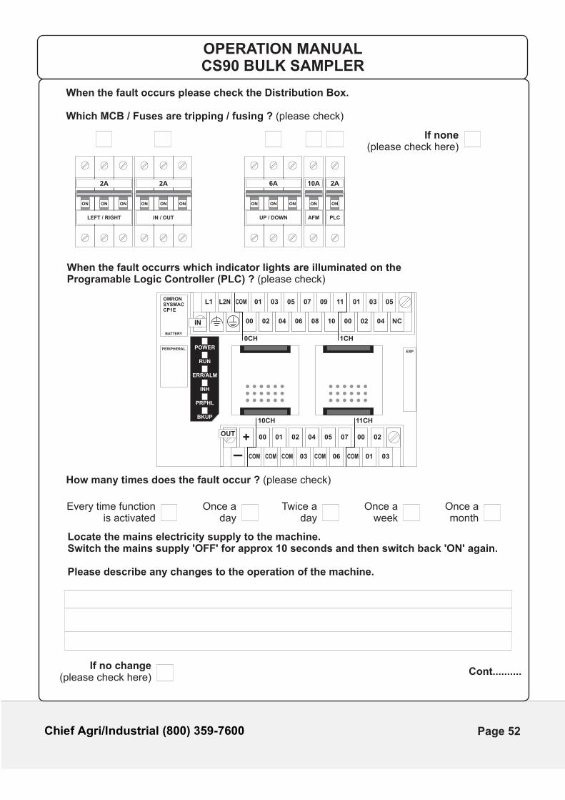
When the fault occurs please check the Distribution Box.
Which MCB / Fuses are tripping / fusing ? (please check)
How many times does the fault occur ? (please check)
Locate the mains electricity supply to the machine.Switch the mains supply 'OFF' for approx 10 seconds and then switch back 'ON' again.
Please describe any changes to the operation of the machine.
When the fault occurrs which indicator lights are illuminated on theProgramable Logic Controller (PLC) ? (please check)
If none(please check here)
ON
10A
AFM
ON
2A
PLC
ONONON
UP / DOWN
6A
ONONON
LEFT / RIGHT
2A
ONONON
IN / OUT
2A
Every time functionis activated
Once aday
Twice aday
Once aweek
Once amonth
If no change(please check here)
Cont..........
OPERATION MANUALCS90 BULK SAMPLER
EXP
L1 L2N COM 01 03 05 07 09 11 01 03 05
NC040200100806040200
0CH 1CH
IN
COMCOMCOMCOMCOM
10CH 11CH
+
-
00 01 02 04
03
05 07
06
00 02
01 03
OUT
POWER
RUN
ERR/ALM
INH
PRPHL
BKUP
PERIPHERAL
BATTERY
OMRONSYSMACCP1E
Page 52
Chief Agri/Industrial (800) 359-7600
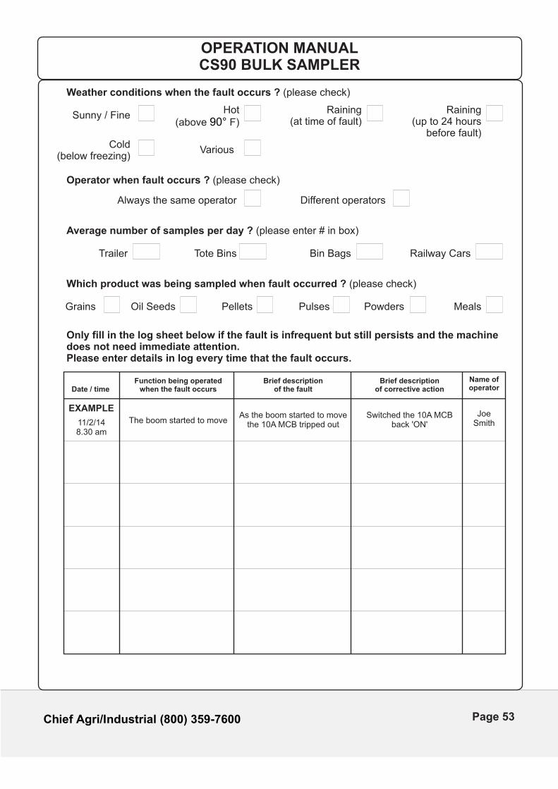
Weather conditions when the fault occurs ? (please check)
Average number of samples per day ? (please enter # in box)
Which product was being sampled when fault occurred ? (please check)
Only fill in the log sheet below if the fault is infrequent but still persists and the machinedoes not need immediate attention.Please enter details in log every time that the fault occurs.
Operator when fault occurs ? (please check)
Hot(above F)90°
Sunny / Fine
Trailer Tote Bins Bin Bags Railway Cars
Always the same operator Different operators
VariousCold
(below freezing)
Raining(at time of fault)
Raining(up to 24 hours
before fault)
Oil SeedsGrains
Date / time
11/2/148.30 am
EXAMPLE
Function being operatedwhen the fault occurs
The boom started to move
Brief descriptionof the fault
As the boom started to movethe 10A MCB tripped out
Brief descriptionof corrective action
Switched the 10A MCBback 'ON'
Name ofoperator
JoeSmith
Pellets Pulses Powders Meals
OPERATION MANUALCS90 BULK SAMPLER
Page 53
Chief Agri/Industrial (800) 359-7600
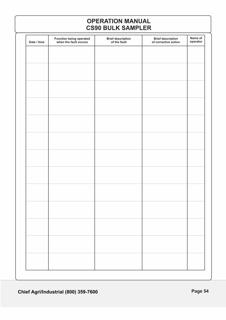
Date / timeFunction being operated
when the fault occursBrief description
of the faultBrief description
of corrective action
Name ofoperator
OPERATION MANUALCS90 BULK SAMPLER
Page 54
Should you have any questions concerning assembly instructions, parts or drawings, please feel free to contact us at the following.
Chief Industries, Inc.Agri/Industrial Division
4400 East 39th Street Kearney, NE 68847PO Box 848 Kearney, NE 68848
Phone: 800.359.7600308.237.3186
Fax: 308.389.6703E-mail: [email protected]
For more information about Chief Industries, Inc. and additional products or services visit our website.
www.agri.chiefind.com
www.chiefind.com
“We Engineer Relationships”
Chief Agri/Industrial (800) 359-7600
Page 55
Recommended