February 12, 2014 Physics for Scientists & Engineers 2, Chapter 25 1
Current and Resistance

Helproom hours ! Strosacker learning center, BPS 1248
! Mo: 10am – noon, 1pm – 9pm ! Tue: noon – 6pm ! We: noon – 2pm ! Th: 10am – 1pm, 2pm – 7pm ! Fri: noon to 2pm
February 12, 2014 Physics for Scientists & Engineers 2, Chapter 21 2
February 12, 2014 Physics for Scientists & Engineers 2, Chapter 25 3
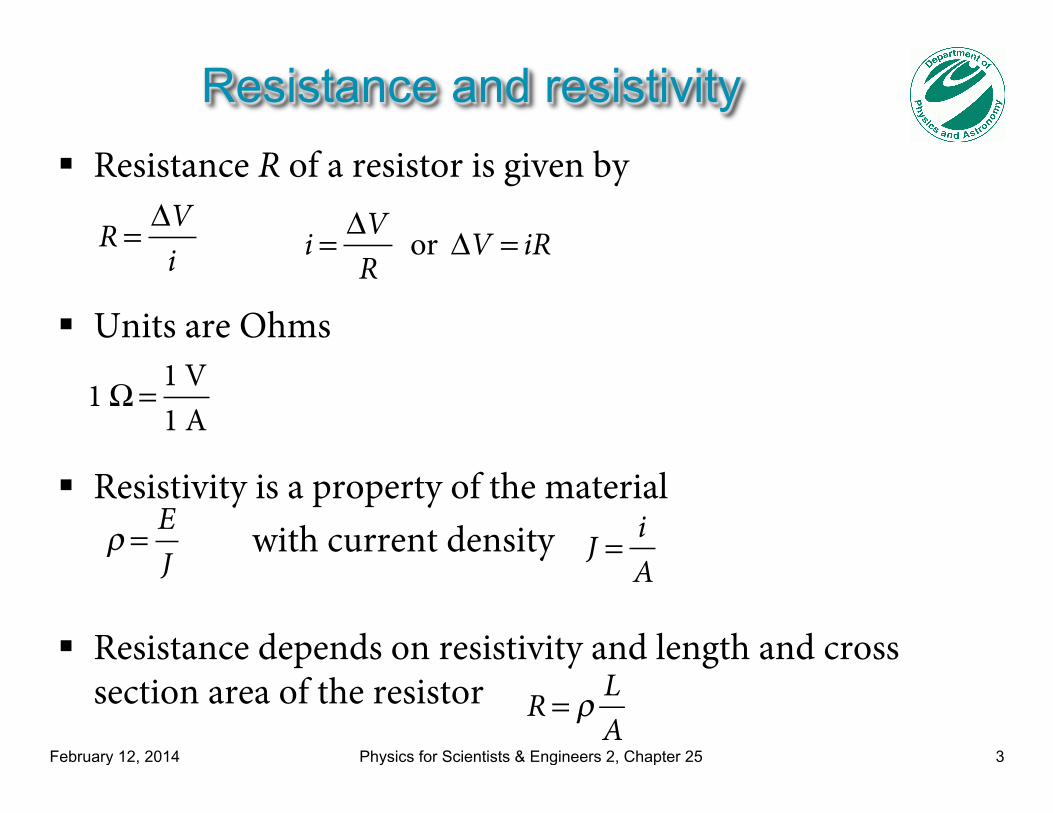
Resistance and resistivity ! Resistance R of a resistor is given by
! Units are Ohms
! Resistivity is a property of the material with current density ! Resistance depends on resistivity and length and cross
section area of the resistor
R = ΔV
i
1 Ω = 1 V
1 A
i = ΔV
R or ΔV = iR
ρ = E
J J = i
A
R = ρ L
A
February 12, 2014 Physics for Scientists & Engineers 2, Chapter 25 4
Temperature Dependence of Resistivity
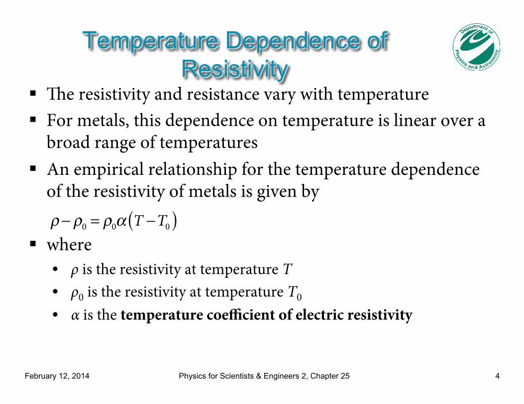
! The resistivity and resistance vary with temperature ! For metals, this dependence on temperature is linear over a
broad range of temperatures ! An empirical relationship for the temperature dependence
of the resistivity of metals is given by
! where • ρ is the resistivity at temperature T • ρ0 is the resistivity at temperature T0
• α is the temperature coefficient of electric resistivity
ρ− ρ0 = ρ0α T −T0( )
February 12, 2014 Physics for Scientists & Engineers 2, Chapter 25 5
Temperature Dependence of Resistance
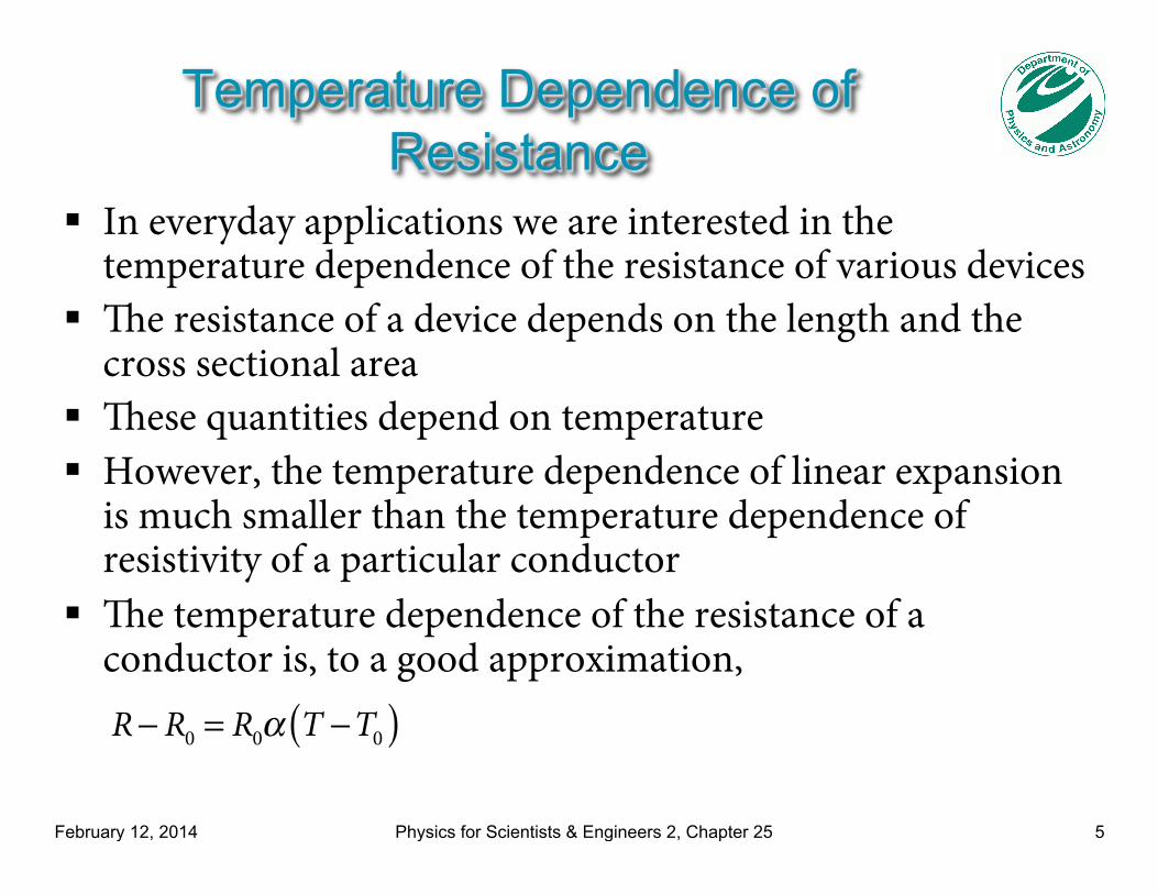
! In everyday applications we are interested in the temperature dependence of the resistance of various devices
! The resistance of a device depends on the length and the cross sectional area
! These quantities depend on temperature ! However, the temperature dependence of linear expansion
is much smaller than the temperature dependence of resistivity of a particular conductor
! The temperature dependence of the resistance of a conductor is, to a good approximation,
R− R0 = R0α T −T0( )
February 12, 2014 Physics for Scientists & Engineers 2, Chapter 25 6
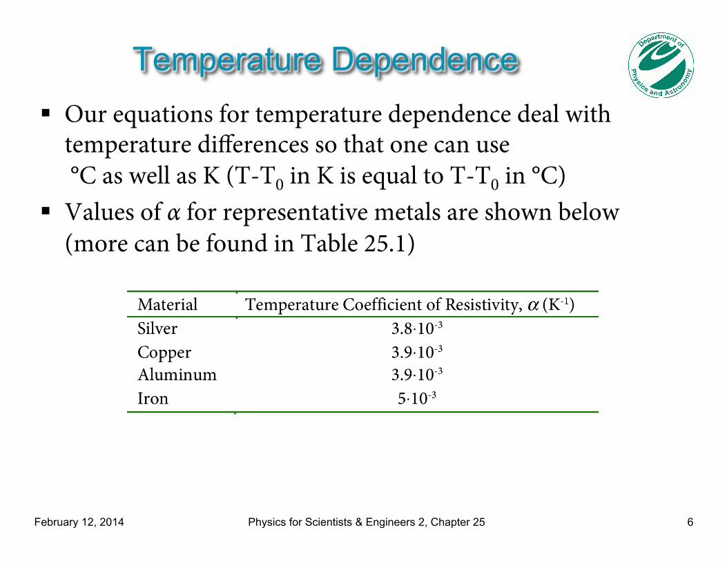
Temperature Dependence ! Our equations for temperature dependence deal with
temperature differences so that one can use °C as well as K (T-T0 in K is equal to T-T0 in °C)
! Values of α for representative metals are shown below (more can be found in Table 25.1)
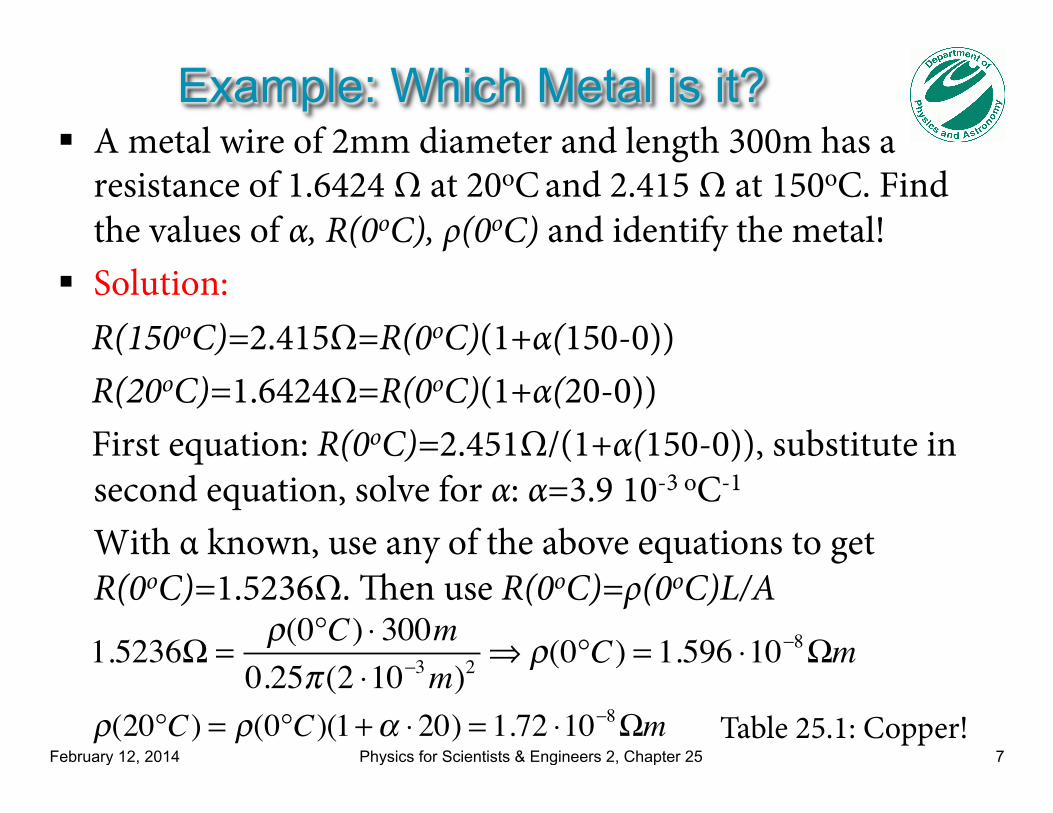
Example: Which Metal is it? ! A metal wire of 2mm diameter and length 300m has a
resistance of 1.6424 Ω at 20oC and 2.415 Ω at 150oC. Find the values of α, R(0oC), ρ(0oC) and identify the metal!
! Solution: R(150oC)=2.415Ω=R(0oC)(1+α(150-0)) R(20oC)=1.6424Ω=R(0oC)(1+α(20-0)) First equation: R(0oC)=2.451Ω/(1+α(150-0)), substitute in
second equation, solve for α: α=3.9 10-3 oC-1
With α known, use any of the above equations to get R(0oC)=1.5236Ω. Then use R(0oC)=ρ(0oC)L/A
February 12, 2014 Physics for Scientists & Engineers 2, Chapter 25 7
1.5236Ω =ρ(0°C) ⋅ 300m0.25π (2 ⋅10−3m)2
⇒ ρ(0°C) = 1.596 ⋅10−8Ωm
ρ(20°C) = ρ(0°C)(1+α ⋅20) = 1.72 ⋅10−8Ωm Table 25.1: Copper!
February 12, 2014 Physics for Scientists & Engineers 2, Chapter 25 8
Other Temperature Dependence
! Most materials have a resistivity that varies linearly with the temperature under ordinary circumstances
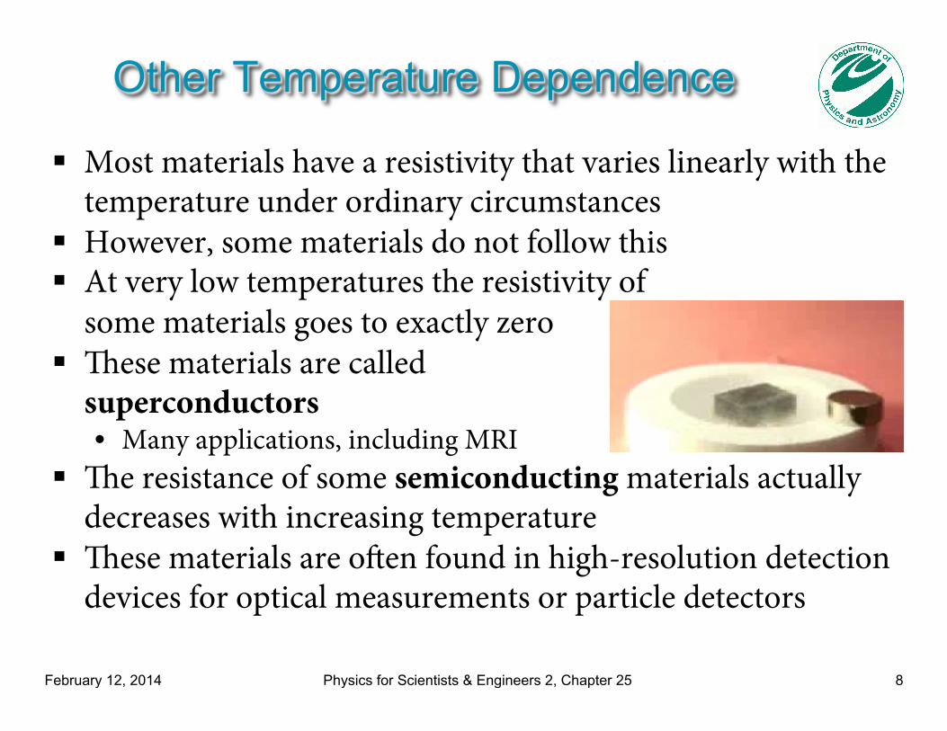
! However, some materials do not follow this ! At very low temperatures the resistivity of
some materials goes to exactly zero ! These materials are called
superconductors • Many applications, including MRI
! The resistance of some semiconducting materials actually decreases with increasing temperature
! These materials are often found in high-resolution detection devices for optical measurements or particle detectors
February 12, 2014 Physics for Scientists & Engineers 2, Chapter 25 9
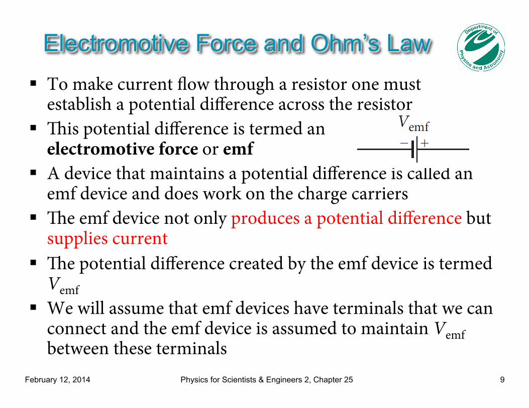
Electromotive Force and Ohm’s Law ! To make current flow through a resistor one must
establish a potential difference across the resistor ! This potential difference is termed an
electromotive force or emf ! A device that maintains a potential difference is called an
emf device and does work on the charge carriers ! The emf device not only produces a potential difference but
supplies current ! The potential difference created by the emf device is termed
Vemf ! We will assume that emf devices have terminals that we can
connect and the emf device is assumed to maintain Vemf between these terminals
February 12, 2014 Physics for Scientists & Engineers 2, Chapter 25 10
Circuit ! Examples of emf devices are
• Batteries that produce emf through chemical reactions • Electric generators that create emf from electromagnetic induction • Solar cells that convert energy from the Sun to electric energy
! We will often use DC (direct current) power supplies, which supply emf just like a battery
! A circuit is an arrangement of electrical components connected together with ideal conducting wires (i.e., having no resistance)
! Electrical components can be sources of emf, capacitors, resistors, or other electrical devices
! We will begin with simple circuits that consist of resistors and sources of emf
February 12, 2014 Physics for Scientists & Engineers 2, Chapter 25 11
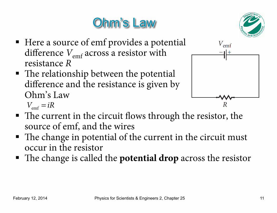
Ohm’s Law ! Here a source of emf provides a potential
difference Vemf across a resistor with resistance R
! The relationship between the potential difference and the resistance is given by Ohm’s Law
! The current in the circuit flows through the resistor, the source of emf, and the wires
! The change in potential of the current in the circuit must occur in the resistor
! The change is called the potential drop across the resistor
Vemf = iR
February 12, 2014 Physics for Scientists & Engineers 2, Chapter 25 12
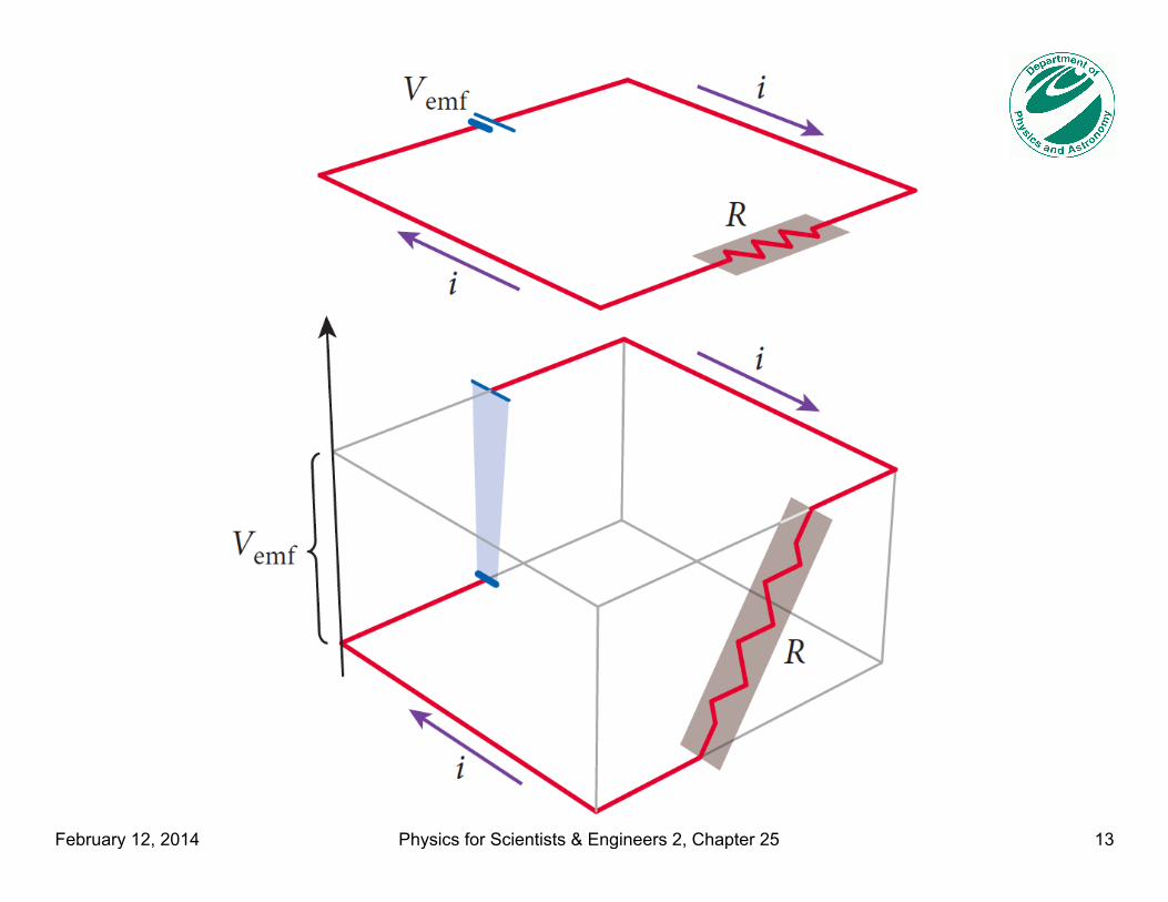
Ohm’s Law ! We can represent the previous circuit in a different way,
making it clearer where the potential drop happens and showing which parts of the circuit are at which potential
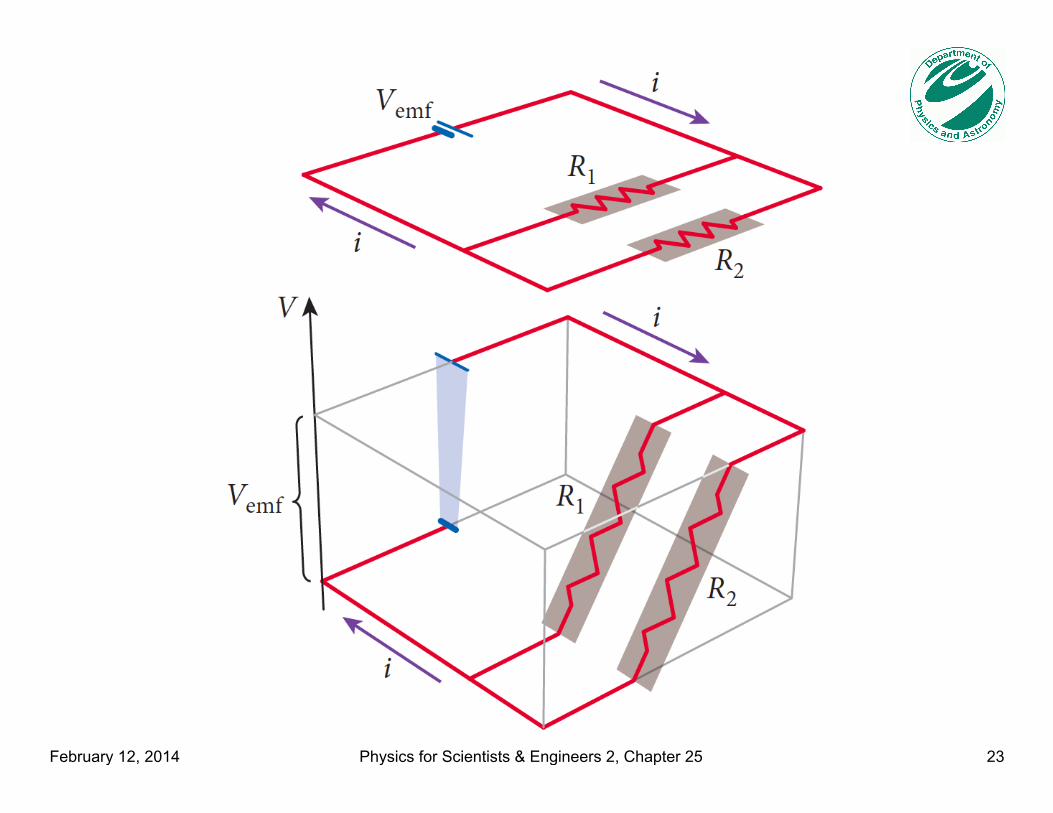
! On the next slide, the top part of the figure shows the previous circuit while the bottom part shows the same circuit but with the vertical dimension representing the value of the electric potential at different points around the circuit
! The potential difference is supplied by the source of emf, and the entire potential drop occurs across the single resistor
! Ohm’s Law applies for the potential drop across the resistor
February 12, 2014 Physics for Scientists & Engineers 2, Chapter 25 13
February 12, 2014 Physics for Scientists & Engineers 2, Chapter 25 14
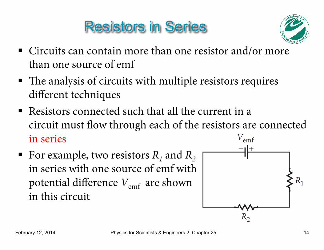
Resistors in Series ! Circuits can contain more than one resistor and/or more
than one source of emf ! The analysis of circuits with multiple resistors requires
different techniques ! Resistors connected such that all the current in a
circuit must flow through each of the resistors are connected in series
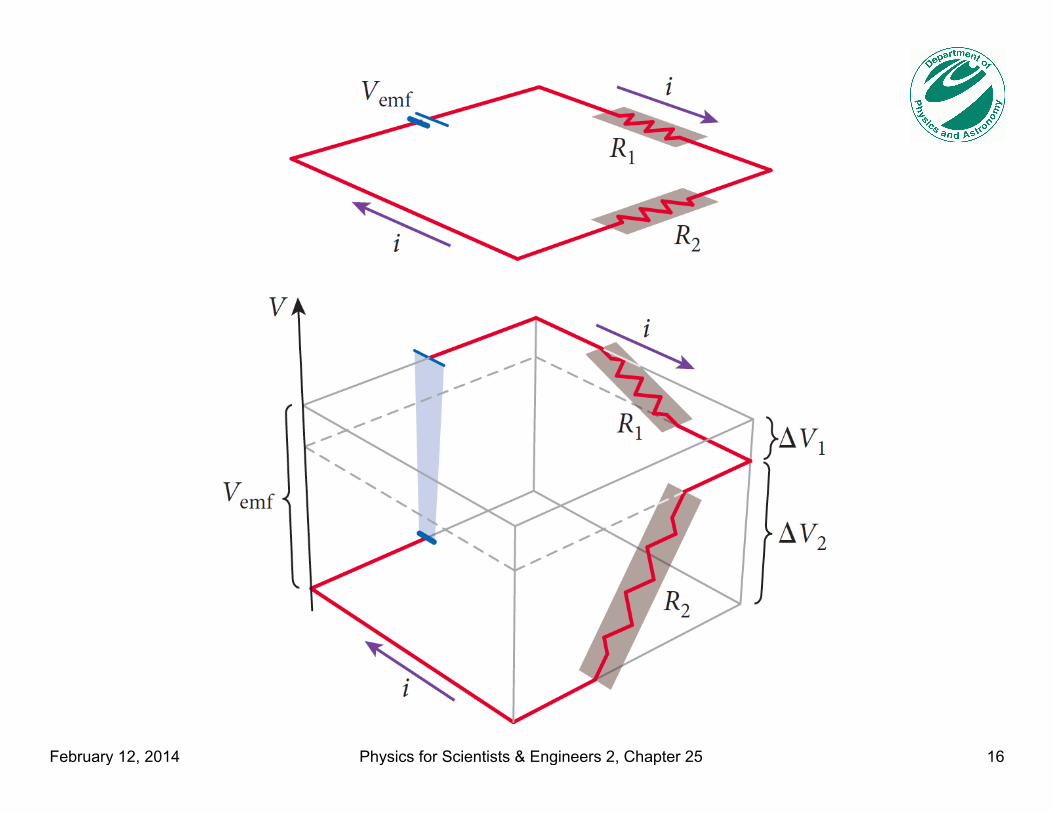
! For example, two resistors R1 and R2 in series with one source of emf with potential difference Vemf are shown in this circuit
February 12, 2014 Physics for Scientists & Engineers 2, Chapter 25 15
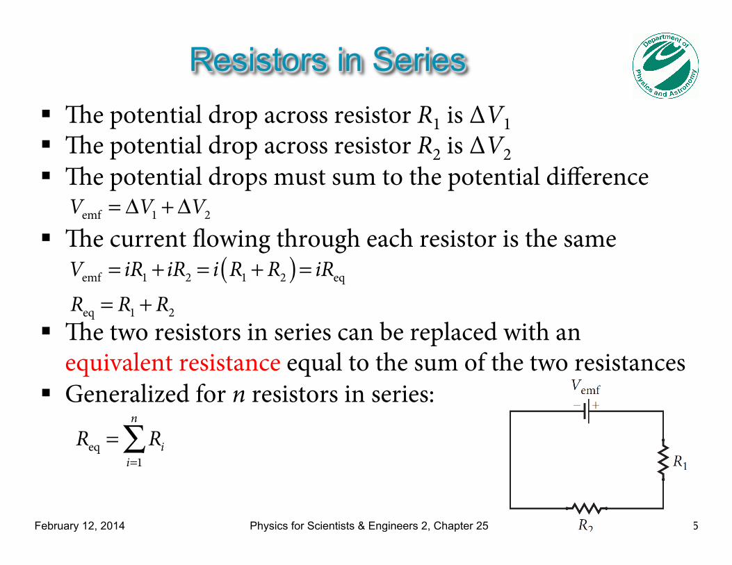
Resistors in Series ! The potential drop across resistor R1 is ΔV1 ! The potential drop across resistor R2 is ΔV2 ! The potential drops must sum to the potential difference
! The current flowing through each resistor is the same
! The two resistors in series can be replaced with an equivalent resistance equal to the sum of the two resistances
! Generalized for n resistors in series:
Vemf = ΔV1 +ΔV2
Vemf = iR1 + iR2 = i R1 + R2( ) = iReq
Req = R1 + R2
Req = Ri
i=1
n
∑
February 12, 2014 Physics for Scientists & Engineers 2, Chapter 25 16
February 12, 2014 Physics for Scientists & Engineers 2, Chapter 25 18
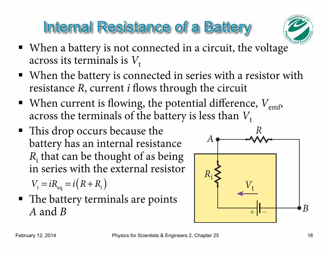
! When a battery is not connected in a circuit, the voltage across its terminals is Vt
! When the battery is connected in series with a resistor with resistance R, current i flows through the circuit
! When current is flowing, the potential difference, Vemf, across the terminals of the battery is less than Vt
! This drop occurs because the battery has an internal resistance Ri that can be thought of as being in series with the external resistor
! The battery terminals are points A and B
Internal Resistance of a Battery
Vt = iReq = i R+ Ri( )
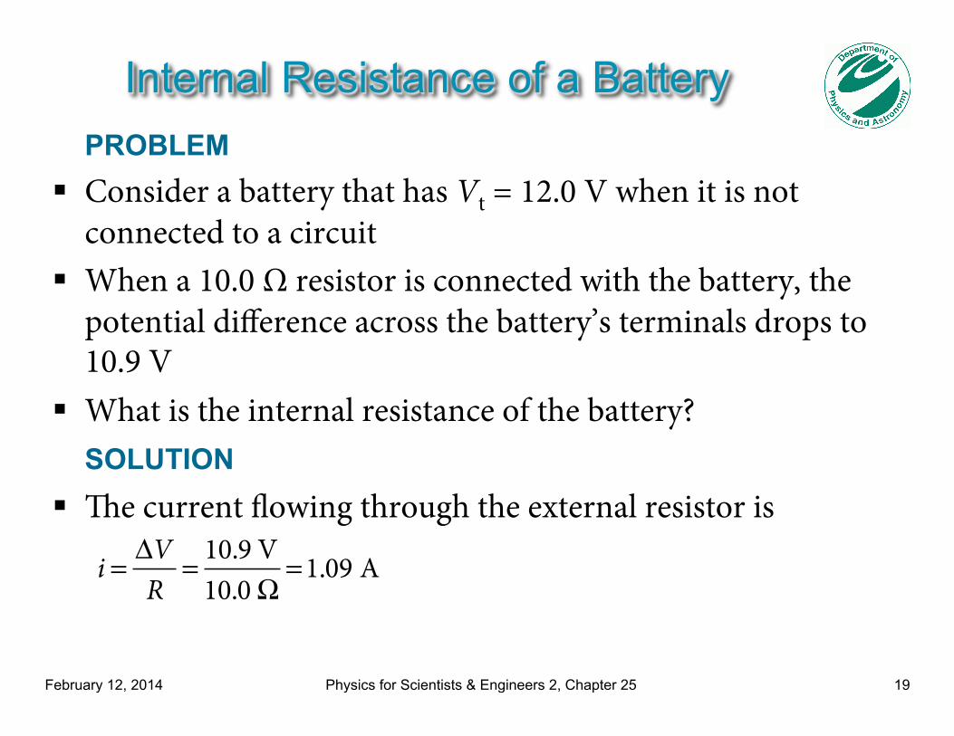
Internal Resistance of a Battery PROBLEM
! Consider a battery that has Vt = 12.0 V when it is not connected to a circuit
! When a 10.0 Ω resistor is connected with the battery, the potential difference across the battery’s terminals drops to 10.9 V
! What is the internal resistance of the battery? SOLUTION
! The current flowing through the external resistor is
February 12, 2014 Physics for Scientists & Engineers 2, Chapter 25 19
i = ΔV
R= 10.9 V
10.0 Ω=1.09 A
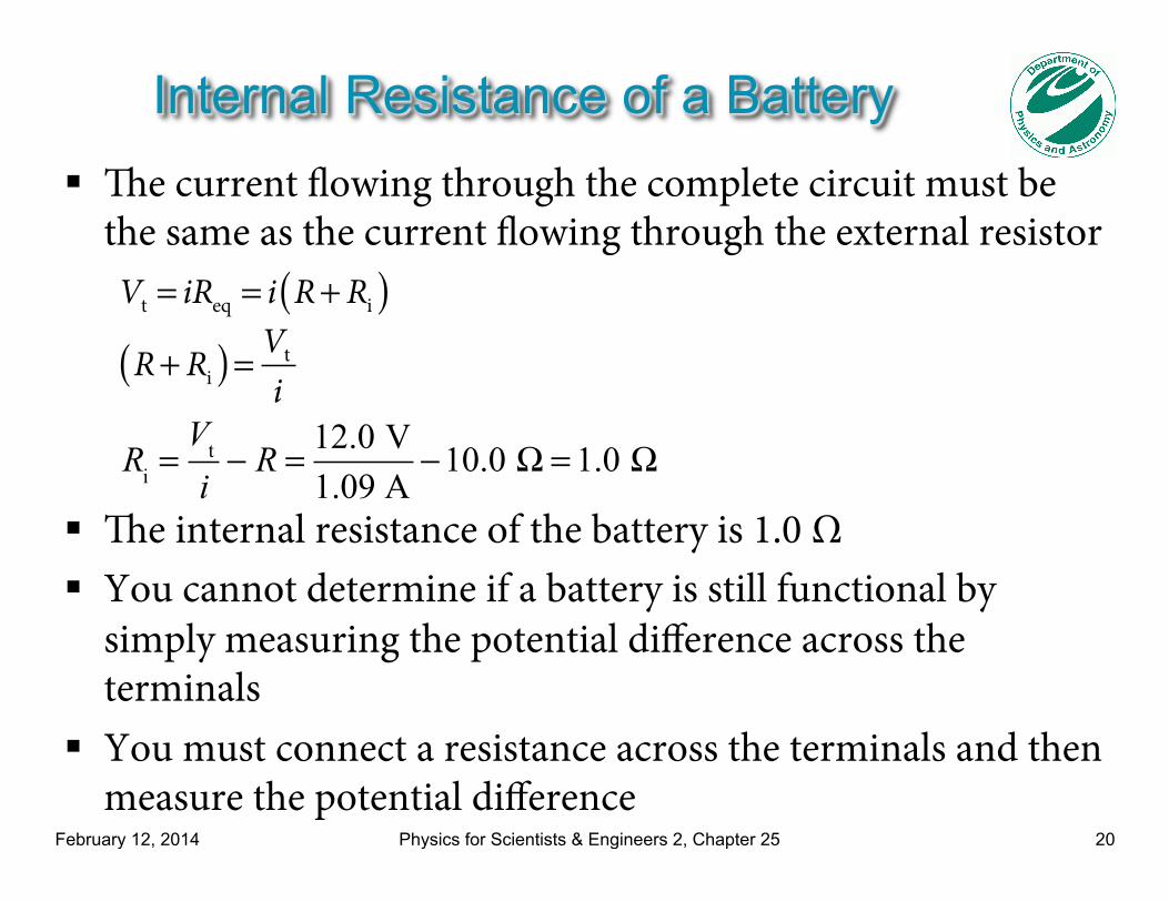
Internal Resistance of a Battery ! The current flowing through the complete circuit must be
the same as the current flowing through the external resistor
! The internal resistance of the battery is 1.0 Ω ! You cannot determine if a battery is still functional by
simply measuring the potential difference across the terminals
! You must connect a resistance across the terminals and then measure the potential difference
February 12, 2014 Physics for Scientists & Engineers 2, Chapter 25 20
Vt = iReq = i R+ Ri( )
Ri =
Vt
i− R = 12.0 V
1.09 A−10.0 Ω = 1.0 Ω
R+ Ri( ) = Vt
i
February 12, 2014 Physics for Scientists & Engineers 2, Chapter 25 22
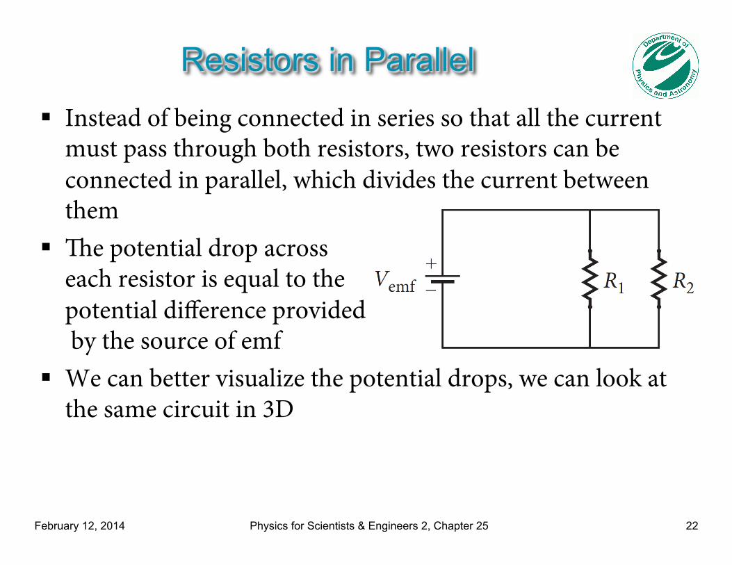
Resistors in Parallel ! Instead of being connected in series so that all the current
must pass through both resistors, two resistors can be connected in parallel, which divides the current between them
! The potential drop across each resistor is equal to the potential difference provided by the source of emf
! We can better visualize the potential drops, we can look at the same circuit in 3D
February 12, 2014 Physics for Scientists & Engineers 2, Chapter 25 23
February 12, 2014 Physics for Scientists & Engineers 2, Chapter 25 24
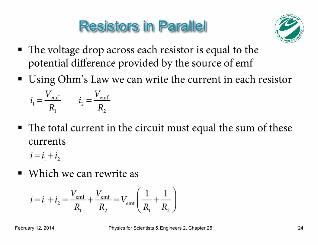
Resistors in Parallel ! The voltage drop across each resistor is equal to the
potential difference provided by the source of emf ! Using Ohm’s Law we can write the current in each resistor
! The total current in the circuit must equal the sum of these currents
! Which we can rewrite as
i1 =
Vemf
R1 i2 =
Vemf
R2
i = i1 + i2
i = i1 + i2 =
Vemf
R1+Vemf
R2=Vemf
1R1
+ 1R2
⎛⎝⎜
⎞⎠⎟
February 12, 2014 Physics for Scientists & Engineers 2, Chapter 25 25
Resistors in Parallel
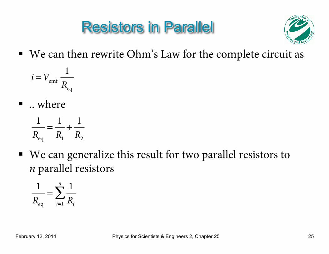
! We can then rewrite Ohm’s Law for the complete circuit as
! .. where
! We can generalize this result for two parallel resistors to n parallel resistors
i =Vemf
1Req
1Req
= 1R1
+ 1R2
1Req
= 1Rii=1
n
∑
Recommended