UNIVERSITY OF ADELAIDE
FACULTY OF ENGINEERING, COMPUTER & MATHEMATICAL SCIENCES
SCHOOL OF MECHANICAL ENGINEERING
MECH ENG 4135: MECHATRONICS HONOURS PROJECT
899: BALLBOT
Preliminary Report
AUTHORS:
Justin FONG
Simon UPPILL
SUPERVISOR:
Ben CAZZOLATO
May 22, 2009
BALLBOT - PRELIMINARY REPORT
Executive Summary
A ballbot is a robot which utilises the concept of dynamic stability to remain upright and bal-
anced on a ball. This involves using control theory to actuate the ball and balance, rather than
relying on gravity and a large wheel base. Only two ballbots had been constructed at the com-
mencement of this project - the first by the Robotics Institute at Carnegie Mellon University (CMU)
in 2006, and the second by Tohoku Gakuin University (TGU) in 2008. During the course of the
project, a Lego ballbot has also been created, by Yorihisa Yamamoto.
This project aims to produce two Ballbots, a small scale version constructed from a Lego Mind-
storms Kit, and a larger ballbot with dimensions approximating that of a human being, for use
as promotional and teaching tools at the University of Adelaide. Development of the Ballbots
required derivation of the dynamics, construction of each of the ballbots, and design and imple-
mentation of a controller to stabilise the ballbots.
Derivation of the equations of motion of the ballbot system was performed using the Lagrangian
approach on a simplified ballbot model, resulting in a linearised state space form of the dynamics
of this simplified ballbot model.
Construction of a Lego Ballbot has been completed, using the Lego NXT Mindstorms kit and
other available Lego parts. This Ballbot uses a simple ‘Inverse Mouse-Ball Drive’, developed by
Lauwers et al. (2006), where the ball is actuated by driven wheels on orthogonal sides of the ball.
Design of a Full Scale Ballbot is in progress, and is loosely based on the Lego Ballbot. However, the
Full Scale Ballbot design uses four motors to actuate the ball using omni-wheels, in an arrangement
similar to that proposed by Wu and Hwang (2008). This design allows for greater flexibility, such
as the ability to use different sized balls, while still allowing for the ‘Inverse Mouse-Ball Drive’.
A controller for the ballbot system has been developed using a full state feedback approach,
based on a controller developed by Yamamoto (2008) for a two wheeled balancing robot. This con-
troller has been implemented on the Lego Ballbot, but has not yet been successful at balancing the
Ballbot. Further testing and controller modification will be performed to achieve a stable Ballbot.
Upon achievement of this aim the controller will be extended to allow for command tracking using
a handheld game controller.
The design of the Full Scale Ballbot is yet to be finalised, at which time construction of the Full
Scale Ballbot will commence. Once construction is complete the previously developed controller
will be modified and implemented. This process aims to result in a stable Full Scale Ballbot with
command tracking capabilities.
i
BALLBOT - PRELIMINARY REPORT
Acknowledgements
The authors of this report would like to thank Associate Professor Dr Benjamin Cazzolato for
his guidance, aide and support during the project.
We would also like to thank the 2009 University of Adelaide Open Day Creativity and Innova-
tion Fund for providing funding for this Ballbot Project.
Furthermore we would like to acknowledge the University of Adelaide Mechanical workshop
staff, particularly Richard Pateman for his advice on structural design, and Phil Schmidt for his
assistance with electrical design.
Finally, thanks go to Yorihisa Yamamoto for making available his NXTway-GS and NXT Ballbot
controllers and documentation, and for answering our queries related to these.
ii
BALLBOT - PRELIMINARY REPORT
Disclaimer
The content of this report is entirely the work of the following students from the University of
Adelaide. Any content obtained from other sources has been referenced accordingly.
Justin FONG
Date:
Simon UPPILL
Date:
iii
BALLBOT - PRELIMINARY REPORT CONTENTS
Contents
1 Introduction 1
1.1 Motivation . . . . . . . . . . . . . . . . . . . . . . . . . . . . . . . . . . . . . . . . . . . 1
1.2 Background . . . . . . . . . . . . . . . . . . . . . . . . . . . . . . . . . . . . . . . . . . 2
1.3 Scope and Objectives . . . . . . . . . . . . . . . . . . . . . . . . . . . . . . . . . . . . . 3
2 Literature Review 5
2.1 Equations of Motion . . . . . . . . . . . . . . . . . . . . . . . . . . . . . . . . . . . . . 5
2.1.1 Assumptions . . . . . . . . . . . . . . . . . . . . . . . . . . . . . . . . . . . . . 5
2.1.2 Derivation Method . . . . . . . . . . . . . . . . . . . . . . . . . . . . . . . . . . 5
2.1.3 Exisiting Results . . . . . . . . . . . . . . . . . . . . . . . . . . . . . . . . . . . 6
2.2 Hardware Design . . . . . . . . . . . . . . . . . . . . . . . . . . . . . . . . . . . . . . . 8
2.2.1 Drive Mechanism . . . . . . . . . . . . . . . . . . . . . . . . . . . . . . . . . . . 8
2.2.2 Ball . . . . . . . . . . . . . . . . . . . . . . . . . . . . . . . . . . . . . . . . . . . 10
2.2.3 Tilt Sensors . . . . . . . . . . . . . . . . . . . . . . . . . . . . . . . . . . . . . . 11
2.2.4 Controller Hardware . . . . . . . . . . . . . . . . . . . . . . . . . . . . . . . . . 11
2.3 Theoretical Controller . . . . . . . . . . . . . . . . . . . . . . . . . . . . . . . . . . . . 11
2.3.1 Carnigie Mellon University Controller . . . . . . . . . . . . . . . . . . . . . . . 12
2.3.2 Tohoku Gakuin University Controller . . . . . . . . . . . . . . . . . . . . . . . 12
2.3.3 Sliding-Mode Control . . . . . . . . . . . . . . . . . . . . . . . . . . . . . . . . 13
2.3.4 NXTway-GS Controller . . . . . . . . . . . . . . . . . . . . . . . . . . . . . . . 13
3 Equations of Motion 14
3.1 Assumptions and Definitions . . . . . . . . . . . . . . . . . . . . . . . . . . . . . . . . 14
3.2 Derivation . . . . . . . . . . . . . . . . . . . . . . . . . . . . . . . . . . . . . . . . . . . 15
3.3 Linearisation . . . . . . . . . . . . . . . . . . . . . . . . . . . . . . . . . . . . . . . . . . 18
3.4 Complete Model . . . . . . . . . . . . . . . . . . . . . . . . . . . . . . . . . . . . . . . . 19
4 The Lego Ballbot 21
4.1 Lego NXT Mindstorms Range . . . . . . . . . . . . . . . . . . . . . . . . . . . . . . . . 21
4.1.1 Lego 8527 NXT Mindstorms Kit Included Parts . . . . . . . . . . . . . . . . . 21
4.1.2 Possible Additional Required Parts . . . . . . . . . . . . . . . . . . . . . . . . 22
4.2 Conceptual design . . . . . . . . . . . . . . . . . . . . . . . . . . . . . . . . . . . . . . 22
4.2.1 Drive Mechanism . . . . . . . . . . . . . . . . . . . . . . . . . . . . . . . . . . . 22
4.2.2 Required Components . . . . . . . . . . . . . . . . . . . . . . . . . . . . . . . . 25
4.2.3 Lego Ballbot Layout . . . . . . . . . . . . . . . . . . . . . . . . . . . . . . . . . 25
4.3 Construction of the Lego Ballbot . . . . . . . . . . . . . . . . . . . . . . . . . . . . . . 25
4.3.1 Original Lego Ballbot . . . . . . . . . . . . . . . . . . . . . . . . . . . . . . . . 26
4.3.2 Modifications . . . . . . . . . . . . . . . . . . . . . . . . . . . . . . . . . . . . . 27
4.4 Final Lego Ballbot Parameters . . . . . . . . . . . . . . . . . . . . . . . . . . . . . . . . 28
5 Controller 30
5.1 Suitability of NXTway-GS Controller Program for Modification . . . . . . . . . . . . 30
5.2 Theoretical Controller . . . . . . . . . . . . . . . . . . . . . . . . . . . . . . . . . . . . 31
iv
BALLBOT - PRELIMINARY REPORT CONTENTS
5.2.1 State Space Model of the Lego Ballbot . . . . . . . . . . . . . . . . . . . . . . . 31
5.2.2 Calculating the Lego Ballbot Controller Gains . . . . . . . . . . . . . . . . . . 32
5.2.3 Controller Simulation . . . . . . . . . . . . . . . . . . . . . . . . . . . . . . . . 33
5.3 Controller Implementation . . . . . . . . . . . . . . . . . . . . . . . . . . . . . . . . . . 35
5.3.1 Basic Program Structure . . . . . . . . . . . . . . . . . . . . . . . . . . . . . . . 35
5.3.2 Sensor Reading and State Calculations . . . . . . . . . . . . . . . . . . . . . . . 35
5.3.3 Calculation of Set Points . . . . . . . . . . . . . . . . . . . . . . . . . . . . . . . 37
5.3.4 Theoretical Controller Implementation . . . . . . . . . . . . . . . . . . . . . . 37
5.3.5 Motor Actuation . . . . . . . . . . . . . . . . . . . . . . . . . . . . . . . . . . . 38
5.3.6 Controller Modifications . . . . . . . . . . . . . . . . . . . . . . . . . . . . . . . 38
6 The Full Scale Ballbot 40
6.1 Conceptual Design . . . . . . . . . . . . . . . . . . . . . . . . . . . . . . . . . . . . . . 40
6.2 Component Specification and Selection . . . . . . . . . . . . . . . . . . . . . . . . . . 41
6.2.1 Controller Hardware Selection . . . . . . . . . . . . . . . . . . . . . . . . . . . 41
6.2.2 Tilt Sensors . . . . . . . . . . . . . . . . . . . . . . . . . . . . . . . . . . . . . . 41
6.2.3 Motors . . . . . . . . . . . . . . . . . . . . . . . . . . . . . . . . . . . . . . . . . 42
6.2.4 Power Supply . . . . . . . . . . . . . . . . . . . . . . . . . . . . . . . . . . . . . 42
6.2.5 Frame Material . . . . . . . . . . . . . . . . . . . . . . . . . . . . . . . . . . . . 43
6.2.6 Ball . . . . . . . . . . . . . . . . . . . . . . . . . . . . . . . . . . . . . . . . . . . 43
6.2.7 Wheels . . . . . . . . . . . . . . . . . . . . . . . . . . . . . . . . . . . . . . . . . 43
6.3 Structural Design . . . . . . . . . . . . . . . . . . . . . . . . . . . . . . . . . . . . . . . 44
6.3.1 Main Frame . . . . . . . . . . . . . . . . . . . . . . . . . . . . . . . . . . . . . . 44
6.3.2 Motor Shaft Extension . . . . . . . . . . . . . . . . . . . . . . . . . . . . . . . . 45
6.3.3 Motor/Wheel Bracket . . . . . . . . . . . . . . . . . . . . . . . . . . . . . . . . 46
6.3.4 Complete Structural Assembly . . . . . . . . . . . . . . . . . . . . . . . . . . . 46
6.4 Electrical Design . . . . . . . . . . . . . . . . . . . . . . . . . . . . . . . . . . . . . . . . 47
6.4.1 Motor Integration . . . . . . . . . . . . . . . . . . . . . . . . . . . . . . . . . . . 47
6.4.2 Tilt Sensor Integration . . . . . . . . . . . . . . . . . . . . . . . . . . . . . . . . 48
6.4.3 Power Distribution and Signal Routing . . . . . . . . . . . . . . . . . . . . . . 48
7 Future Work 49
7.1 Lego Ballbot . . . . . . . . . . . . . . . . . . . . . . . . . . . . . . . . . . . . . . . . . . 49
7.1.1 Controller Testing and Refinement . . . . . . . . . . . . . . . . . . . . . . . . . 49
7.1.2 Command Tracking . . . . . . . . . . . . . . . . . . . . . . . . . . . . . . . . . 49
7.1.3 Bluetooth Control . . . . . . . . . . . . . . . . . . . . . . . . . . . . . . . . . . . 49
7.2 Full Scale Ballbot . . . . . . . . . . . . . . . . . . . . . . . . . . . . . . . . . . . . . . . 49
7.2.1 Detail Design . . . . . . . . . . . . . . . . . . . . . . . . . . . . . . . . . . . . . 50
7.2.2 Construction . . . . . . . . . . . . . . . . . . . . . . . . . . . . . . . . . . . . . 50
7.2.3 Controller . . . . . . . . . . . . . . . . . . . . . . . . . . . . . . . . . . . . . . . 50
A Matlab Code 52
B Simulink Controller 66
v
BALLBOT - PRELIMINARY REPORT CONTENTS
C Gantt Chart 90
D Component Datasheets 92
E NXT Mindstorms Parts List 100
vi
BALLBOT - PRELIMINARY REPORT LIST OF TABLES
List of Figures
1 A Segway (Segway Inc, 2009) . . . . . . . . . . . . . . . . . . . . . . . . . . . . . . . . 2
2 Existing Ballbots . . . . . . . . . . . . . . . . . . . . . . . . . . . . . . . . . . . . . . . . 3
3 Generalised coordinates for ball/wheel balancing systems . . . . . . . . . . . . . . . 6
4 Driving Mechanism of CMU Ballbot (Lauwers et al., 2006) . . . . . . . . . . . . . . . 8
5 Driving Mechanism of TGU Ballbot (Kumagai and Ochiai, 2008) . . . . . . . . . . . . 9
6 A Proposed Drive Mechanism using Four Omniwheels (Wu and Hwang, 2008) . . . 10
7 Structure of the Controller used on the CMU Ballbot (Lauwers et al., 2006) . . . . . . 12
8 Structure of the Controller used in the NXTway-GS (Yamamoto, 2008) . . . . . . . . 14
9 The Simplified Ballbot Model . . . . . . . . . . . . . . . . . . . . . . . . . . . . . . . . 15
10 Lego Wheels considered for use in the Lego Ballbot . . . . . . . . . . . . . . . . . . . 22
11 Drive mechanism concepts . . . . . . . . . . . . . . . . . . . . . . . . . . . . . . . . . . 23
12 Layout of the Lego Ballbot . . . . . . . . . . . . . . . . . . . . . . . . . . . . . . . . . . 26
13 Lego Ballbot: The Frame for the Drive Mechanism . . . . . . . . . . . . . . . . . . . . 27
14 Lego Ballbot: Sensor Locations . . . . . . . . . . . . . . . . . . . . . . . . . . . . . . . 27
15 Lego Ballbot: Complete . . . . . . . . . . . . . . . . . . . . . . . . . . . . . . . . . . . . 28
16 Lego Ballbot: Lego Ballbot Modifications . . . . . . . . . . . . . . . . . . . . . . . . . 28
17 Final Lego Ballbot, showing coordinate system and states . . . . . . . . . . . . . . . . 29
18 Addition of Integral Control State on Ballbot Controller (adapted from Yamamoto
(2008)) . . . . . . . . . . . . . . . . . . . . . . . . . . . . . . . . . . . . . . . . . . . . . 32
19 Controller Simulator Program . . . . . . . . . . . . . . . . . . . . . . . . . . . . . . . . 33
20 Controller Simulation Results . . . . . . . . . . . . . . . . . . . . . . . . . . . . . . . . 34
21 Application Subsystems of the Controller . . . . . . . . . . . . . . . . . . . . . . . . . 35
22 Measurement and Calculation of States . . . . . . . . . . . . . . . . . . . . . . . . . . 36
23 Calculation of the Gyroscope Offset . . . . . . . . . . . . . . . . . . . . . . . . . . . . 36
24 Multiplication by Controller Gains . . . . . . . . . . . . . . . . . . . . . . . . . . . . . 37
25 Manipulation of the Controller Output Signal . . . . . . . . . . . . . . . . . . . . . . . 38
26 Generation of the θ Estimation using a Complementary Filter . . . . . . . . . . . . . 39
27 Concepts for the Full Scale Drive Mechanism Frame (shown in one plane) . . . . . . 40
28 Omniwheel Candidates . . . . . . . . . . . . . . . . . . . . . . . . . . . . . . . . . . . 44
29 Full Scale Ballbot Frame . . . . . . . . . . . . . . . . . . . . . . . . . . . . . . . . . . . 45
30 Motor Shaft Extension . . . . . . . . . . . . . . . . . . . . . . . . . . . . . . . . . . . . 46
31 Full Scale Ballbot Motor/Wheel Bracket Assembly . . . . . . . . . . . . . . . . . . . . 46
32 Full Scale Ballbot Structural Design . . . . . . . . . . . . . . . . . . . . . . . . . . . . . 47
33 Power Distribution and Signal Routing . . . . . . . . . . . . . . . . . . . . . . . . . . 48
List of Tables
1 Generalised Coordinate Relationships: Ball . . . . . . . . . . . . . . . . . . . . . . . . 16
2 Generalised Coordinate Relationships: Body . . . . . . . . . . . . . . . . . . . . . . . 16
3 Generalised Coordinate Relationships: Motors . . . . . . . . . . . . . . . . . . . . . . 17
4 Decision Matrix for Lego Ballbot Drive Mechanism . . . . . . . . . . . . . . . . . . . 24
5 Lego Ballbot Physical Parameters . . . . . . . . . . . . . . . . . . . . . . . . . . . . . . 29
vii
BALLBOT - PRELIMINARY REPORT 1 INTRODUCTION
1 Introduction
The concept of a ballbot is simple - it is a robot, which balances on a ball. The ball therefore
acts as the single spherical wheel, allowing the robot to travel in any direction. In contrast to
traditional robots, which rely on a low centre of mass and large wheel-base to remain upright,
ballbots must actively balance, resulting in dynamic stability. It is hoped that with the development
of ballbots, and associated technology, robots which can act as human-sized ‘personal assistants’
can be created.
This project aims to design and build two Ballbots, primarily for educational purposes. The first
is a ballbot constructed out of a Lego NXT Mindstorms Kit which can be used as a small teaching
aide within a classroom environment. The second proposed ballbot is a Full-Scale Ballbot, which
can be used at the University of Adelaide for promotional reasons.
The development of these ballbots is a full systems project, including derivation of equations
of motion of a generalised ballbot, design and construction of the two ballbots, design and imple-
mentation of a controller and relevant software to balance each ballbot, and testing of the systems.
The educational aspect of this project requires that these components of the project be documented
clearly for student use.
1.1 Motivation
Man has long dreamed of robotic personal aides, created to perform his every task. The idea
of automation appeals not only to those who perhaps are too lazy to complete the task itself, but
to those dreaming of increasing productivity or efficiency within their own lives. This ideal un-
fortunately does not lie within reach of current technology, but research has been conducted into
individual requirements of such an aide.
One such requirements is for the robot to be of a similar size and shape to that of a human
being. Many existing robots involve the use of three or four wheels, to establish a large enough
wheel-base such that the robot is able to ‘stand’ upright. However, relying on the size of the wheel-
base limits the robots performance, as the wheel-base must be significantly less than the height to
maintain a human-like shape. Thus only a small shift in the position of the centre of gravity is
required to cause the robot to become unstable. This may be corrected by lowering the centre of
gravity of the robot to reduce the lever-arm, however, this generally comes at the cost of significant
dead-weight being added to the robot. Additionally, given the instability of the robot, the speed at
which the robot can travel is generally limited lest the robot’s momentum causes it to tip over.
One plausible solution to this problem, and the one developed in the ballbot projects, is dynamic
stability. That is, control theory is used to ensure that the robot stays upright, without the need
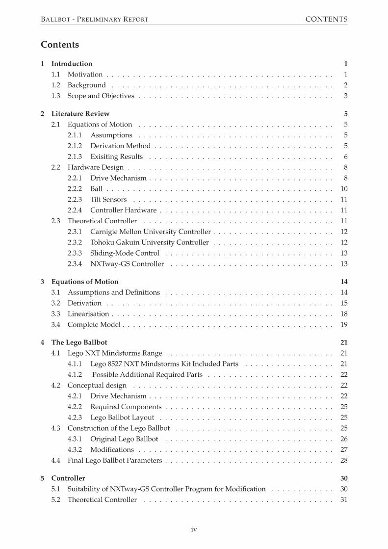
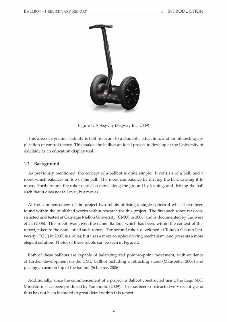
to rely on static stability. Dynamic stability has been utilised most famously on the single-person
transport unit, the Segway. The Segway (Figure 1) has two axially-aligned wheels, and utilises the
solution to the ‘Inverted Pendulum’ control problem.
1
BALLBOT - PRELIMINARY REPORT 1 INTRODUCTION
Figure 1: A Segway (Segway Inc, 2009)
This area of dynamic stability is both relevant to a student’s education, and an interesting ap-
plication of control theory. This makes the ballbot an ideal project to develop at the University of
Adelaide as an education display tool.
1.2 Background
As previously mentioned, the concept of a ballbot is quite simple. It consists of a ball, and a
robot which balances on top of the ball. The robot can balance by driving the ball, causing it to
move. Furthermore, the robot may also move along the ground by leaning, and driving the ball
such that it does not fall over, but moves.
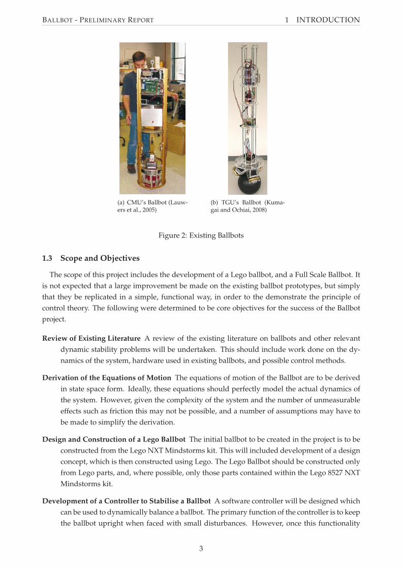
At the commencement of the project two robots utilising a single spherical wheel have been
found within the published works within research for this project. The first such robot was con-
structed and tested at Carnegie Mellon University (CMU) in 2006, and is documented by Lauwers
et al. (2006). This robot, was given the name ‘Ballbot’ which has been, within the context of this
report, taken to the name of all such robots. The second robot, developed at Tohoku Gakuin Uni-
versity (TGU) in 2007, is similar, but uses a more complex driving mechanism, and presents a more
elegant solution. Photos of these robots can be seen in Figure 2.
Both of these ballbots are capable of balancing and point-to-point movement, with evidence
of further development on the CMU ballbot including a retracting stand (Mampetta, 2006) and
placing an arm on top of the ballbot (Schearer, 2006).
Additionally, since the commencement of a project, a Ballbot constructed using the Lego NXT
Mindstorms has been produced by Yamamoto (2009). This has been constructed very recently, and
thus has not been included in great detail within this report.
2
BALLBOT - PRELIMINARY REPORT 1 INTRODUCTION
(a) CMU’s Ballbot (Lauw-ers et al., 2005)
(b) TGU’s Ballbot (Kuma-gai and Ochiai, 2008)
Figure 2: Existing Ballbots
1.3 Scope and Objectives
The scope of this project includes the development of a Lego ballbot, and a Full Scale Ballbot. It
is not expected that a large improvement be made on the existing ballbot prototypes, but simply
that they be replicated in a simple, functional way, in order to the demonstrate the principle of
control theory. The following were determined to be core objectives for the success of the Ballbot
project.
Review of Existing Literature A review of the existing literature on ballbots and other relevant
dynamic stability problems will be undertaken. This should include work done on the dy-
namics of the system, hardware used in existing ballbots, and possible control methods.
Derivation of the Equations of Motion The equations of motion of the Ballbot are to be derived
in state space form. Ideally, these equations should perfectly model the actual dynamics of
the system. However, given the complexity of the system and the number of unmeasurable
effects such as friction this may not be possible, and a number of assumptions may have to
be made to simplify the derivation.
Design and Construction of a Lego Ballbot The initial ballbot to be created in the project is to be
constructed from the Lego NXT Mindstorms kit. This will included development of a design
concept, which is then constructed using Lego. The Lego Ballbot should be constructed only
from Lego parts, and, where possible, only those parts contained within the Lego 8527 NXT
Mindstorms kit.
Development of a Controller to Stabilise a Ballbot A software controller will be designed which
can be used to dynamically balance a ballbot. The primary function of the controller is to keep
the ballbot upright when faced with small disturbances. However, once this functionality
3
BALLBOT - PRELIMINARY REPORT 1 INTRODUCTION
of the controller is implemented the controller should be extended to allow for command
tracking from a remote source.
Initially the controller will be applied to the Lego Ballbot and the controller will be imple-
mented on the Lego NXT brick. The brick allows for Bluetooth communication and it is
anticipated that this will be used for command tracking purposes.
Design and Construction of a Full Scale Ballbot Based upon the Lego Ballbot, a Full Scale Ball-
bot will be designed and constructed. This ballbot is to be of dimensions similar to a human,
approximately 1.5m tall and no more than 0.7m wide. Design of the Full Scale Ballbot will
include development of the design concept, specification and selection of components, and
detail design including integration of all components.
The controller used for the Full Scale Ballbot will be a modified version of the controller
developed for the Lego Ballbot. It should replicate the functionality of this controller such
that the Full Scale Ballbot can balance upright and allow for command tracking.
In addition to these core objectives, a number of extension goals were determined, as follows.
Create Building Instructions for the Lego Ballbot It is desired that the Lego Ballbot be easily re-
produced for teaching purposes. For this reason, it is desirable that step by step instructions
detailing the construction of the Lego Ballbot be produced.
Produce a Virtual Reality Model of the Lego Ballbot To extend the use of the Lego Ballbot as a
teaching aide, it is desired that a virtual reality model of the Lego Ballbot be produced which
represents the derived equations of motion of the Ballbot and uses the implemented con-
troller.
Extend Functionality of the Ballbots In order to further develop the concept of the Ballbot, the
functionality of the either or both of the Ballbots may be extended beyond simply balancing
and command tracking. This may include yaw control which allows the Ballbot to rotate to
any orientation, or some form of environmental interaction such as obstacle detection or the
ability to follow a path or other object.
At the time of writing not all core objectives and no extension objectives have been achieved.
However the project is progressing as described in the Project Gantt Chart, found in Appendix C.
Objectives which are still to be achieved and the work required to complete these objectives is
discussed in Section 7.
4
BALLBOT - PRELIMINARY REPORT 2 LITERATURE REVIEW
2 Literature Review
The literature review presented in this section details the previous work in three areas of ballbot
development. The first is the derivation of the equations of motion, which are required for control
of the ballbot. The second is the physical construction of the hardware itself. The final area is the
theoretical controller used to maintain the ballbot balancing or following a command.
As ballbots are a relatively undeveloped concept, only a limited literature exists on the topic.
However, as will be discussed in the following sections, the ballbot problem can be modelled as
two independent inverted pendulum systems, a system which is well documented. As such, the
review of previously-derived dynamics and controllers has been extended marginally into solu-
tions for the inverted pendulum problem.
2.1 Equations of Motion
The aim of the review of previously derived equations of motion is to provide a basis to derive
the dynamics of the Ballbot for this project. This includes firstly analysing any assumptions that
can be made when deriving the Ballbot dynamics. Secondly, current methods of deriving the
equations of motion of the Ballbot are discussed. Finally, existing results are examined, including
limitations of these results.
2.1.1 Assumptions
The dynamics of the Ballbot are complex and, for this reason, difficult to derive unless assump-
tions to simplify the model of the Ballbot are made. A simplified Ballbot model consists of a rigid
body balancing atop a rigid sphere. For this model it can be assumed that the motion in the two
planes of tip - pitch and roll - are decoupled and that the equations of motion are identical in these
two planes (Lauwers et al., 2005). This assumption results in the ability to design a controller for
the full 3D system by designing controllers for the two independent planes (Lauwers et al., 2005).
Further assumptions include modelling the friction in the system as viscous friction only, while
ignoring static and non-linear friction effects (Lauwers et al., 2005, 2006, Yamamoto, 2008). Static
and non-linear friction effects introduce discontinuities and severe non-linearities into the model,
which is undesirable for control (Lauwers et al., 2006). The assumptions of a simplified two plane
ballbot model and viscous friction allow the equations of motion to be determined in a form which
allows for controller design.
2.1.2 Derivation Method
The dynamics of the simplified Ballbot model can be derived using the Lagrangian approach,
and has previously been performed by Lauwers et al. (2005) and Liao et al. (2008). This method
defines a quantity the Lagrangian L(q, q, t), where q are the generalized co-ordinates of the system,
and t is time. This quantity L is simply the sum of the kinetic energy of the system, T, minus the
potential energy, U, shown in Equation (1) (Brizard, 2008).
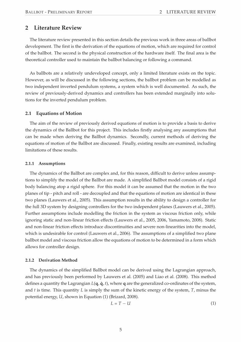
(1)L = T − U
5
BALLBOT - PRELIMINARY REPORT 2 LITERATURE REVIEW
The choice of co-ordinates q is arbitrary, with the constraint that they must fully define the
system. However, it is advantageous to use co-ordinates that directly relate to measurable quan-
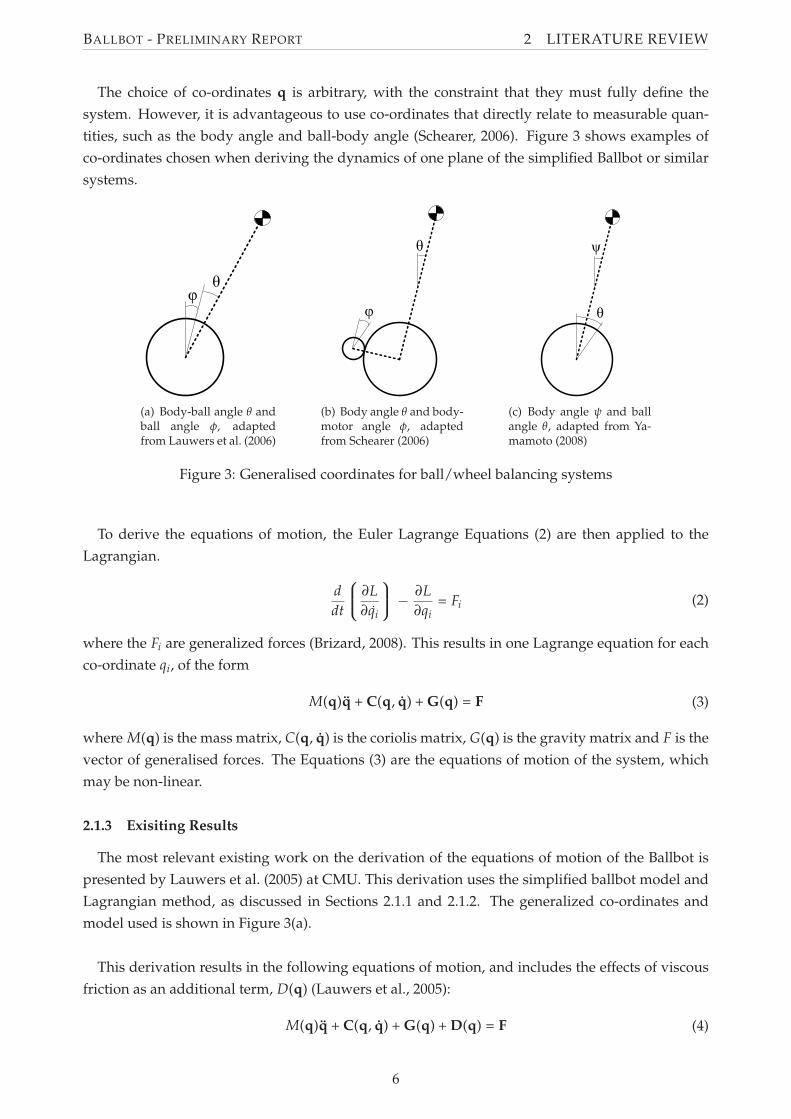
tities, such as the body angle and ball-body angle (Schearer, 2006). Figure 3 shows examples of
co-ordinates chosen when deriving the dynamics of one plane of the simplified Ballbot or similar
systems.
(a) Body-ball angle θ andball angle φ, adaptedfrom Lauwers et al. (2006)
(b) Body angle θ and body-motor angle φ, adaptedfrom Schearer (2006)
(c) Body angle ψ and ballangle θ, adapted from Ya-mamoto (2008)
Figure 3: Generalised coordinates for ball/wheel balancing systems
To derive the equations of motion, the Euler Lagrange Equations (2) are then applied to the
Lagrangian.
(2)d
dt
∂L
∂qi
−∂L
∂qi= Fi
where the Fi are generalized forces (Brizard, 2008). This results in one Lagrange equation for each
co-ordinate qi, of the form
(3)M(q)q + C(q, q) + G(q) = F
where M(q) is the mass matrix, C(q, q) is the coriolis matrix, G(q) is the gravity matrix and F is the
vector of generalised forces. The Equations (3) are the equations of motion of the system, which
may be non-linear.
2.1.3 Exisiting Results
The most relevant existing work on the derivation of the equations of motion of the Ballbot is
presented by Lauwers et al. (2005) at CMU. This derivation uses the simplified ballbot model and
Lagrangian method, as discussed in Sections 2.1.1 and 2.1.2. The generalized co-ordinates and
model used is shown in Figure 3(a).
This derivation results in the following equations of motion, and includes the effects of viscous
friction as an additional term, D(q) (Lauwers et al., 2005):
(4)M(q)q + C(q, q) + G(q) + D(q) = F
6
BALLBOT - PRELIMINARY REPORT 2 LITERATURE REVIEW
where
M(q) =
[
γ1 + 2mBrbl cos(θ + φ) γ1 + mBrbl cos(θ + φ)
γ2 + mBrbl cos(θ + φ) γ2
]
γ1 = Ib + IB + mbr2b + mBr2
b + mBl2
γ2 = mBl2 + IB
C(q, q) =
[
−mBrbl sin(θ + φ)(θ + φ)2
0
]
G(q) =
[
−mBgl sin(θ + φ)
−mBgl sin(θ + φ)
]
D(q) =
[
µθ θ
µφφ
]
F =
[
0
τ
]
These results provide the equations of motion of the Ballbot. A major limitation of these equa-
tions is that the control torques are simply modelled as torques, and do not consider the motor
dynamics. A model which includes the effect of motor dynamics was used by Yamamoto (2008).
While this system is that of an inverted pendulum, not a Ballbot, it is analogous to one plane of
the Ballbot dynamics. The model includes the effect of the motor by adding the motor rotational
kinetic energy to the Lagrangian quantity, and replacing the control torques with dynamics based
on the DC motor Equations (5) and (6).
(5)τ = Kti
subject to
(6)Li = v + Kb θ − Ri
where τ is motor torque, Kt is the motor torque constant, i is motor current, v is motor voltage,
θ is motor angular speed, L is motor inductance, Kb is the motor back emf constant and R is the
motor resistance.
In this application the motor inductance L is negligible and assumed to be zero, resulting in
Equation (7) for applied torque (Yamamoto, 2008). It should be noted that this model only applies
for a voltage controlled DC motor with negligible inductance.
(7)τ =Kt(v + Kb θ)
R
The use of the results of Lauwers et al. (2006) and Yamamoto (2008) provide a basis to derive the
dynamics of the Ballbot.
7
BALLBOT - PRELIMINARY REPORT 2 LITERATURE REVIEW
2.2 Hardware Design
A physical ballbot is a relatively simple device, requiring few components. The basic function-
ality of the ballbot, that is to balance upright on a ball, requires a ball, a means of actuating the
ball, sensors to measure the angle of ballbot tilt, and a microcontroller. The approaches to these
areas vary slightly between the two existing implementations of a full scale ballbot, constructed by
Carnegie Mellon University and Tohoku Gakuin University respectively.
2.2.1 Drive Mechanism
The drive mechanism - including the interface between the driving motors and the ball - is
critical to the success of a ballbot. CMU and TGU take different approaches to the design of this
component, which are discussed following. Furthermore a drive mechanism proposed by Wu and
Hwang (2008) is examined.
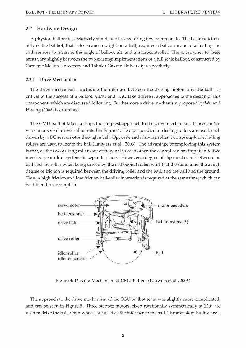
The CMU ballbot takes perhaps the simplest approach to the drive mechanism. It uses an ‘in-
verse mouse-ball drive’ - illustrated in Figure 4. Two perpendicular driving rollers are used, each
driven by a DC servomotor through a belt. Opposite each driving roller, two spring-loaded idling
rollers are used to locate the ball (Lauwers et al., 2006). The advantage of employing this system
is that, as the two driving rollers are orthogonal to each other, the control can be simplified to two
inverted pendulum systems in separate planes. However, a degree of slip must occur between the
ball and the roller when being driven by the orthogonal roller, whilst, at the same time, the a high
degree of friction is required between the driving roller and the ball, and the ball and the ground.
Thus, a high friction and low friction ball-roller interaction is required at the same time, which can
be difficult to accomplish.
Figure 4: Driving Mechanism of CMU Ballbot (Lauwers et al., 2006)
The approach to the drive mechanism of the TGU ballbot team was slightly more complicated,
and can be seen in Figure 5. Three stepper motors, fixed rotationally symmetrically at 120◦ are
used to drive the ball. Omniwheels are used as the interface to the ball. These custom-built wheels
8
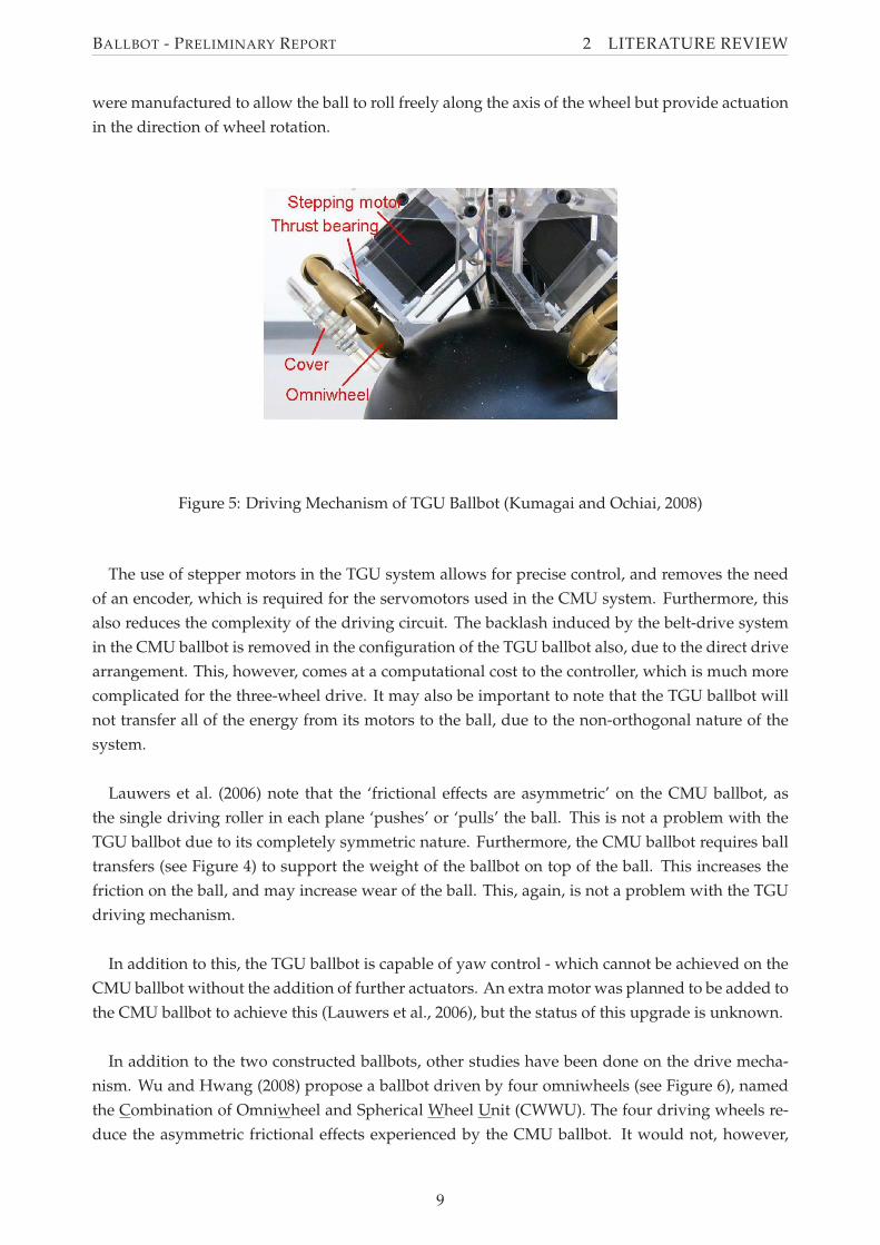
BALLBOT - PRELIMINARY REPORT 2 LITERATURE REVIEW
were manufactured to allow the ball to roll freely along the axis of the wheel but provide actuation
in the direction of wheel rotation.
Figure 5: Driving Mechanism of TGU Ballbot (Kumagai and Ochiai, 2008)
The use of stepper motors in the TGU system allows for precise control, and removes the need
of an encoder, which is required for the servomotors used in the CMU system. Furthermore, this
also reduces the complexity of the driving circuit. The backlash induced by the belt-drive system
in the CMU ballbot is removed in the configuration of the TGU ballbot also, due to the direct drive
arrangement. This, however, comes at a computational cost to the controller, which is much more
complicated for the three-wheel drive. It may also be important to note that the TGU ballbot will
not transfer all of the energy from its motors to the ball, due to the non-orthogonal nature of the
system.
Lauwers et al. (2006) note that the ‘frictional effects are asymmetric’ on the CMU ballbot, as
the single driving roller in each plane ‘pushes’ or ‘pulls’ the ball. This is not a problem with the
TGU ballbot due to its completely symmetric nature. Furthermore, the CMU ballbot requires ball
transfers (see Figure 4) to support the weight of the ballbot on top of the ball. This increases the
friction on the ball, and may increase wear of the ball. This, again, is not a problem with the TGU
driving mechanism.
In addition to this, the TGU ballbot is capable of yaw control - which cannot be achieved on the
CMU ballbot without the addition of further actuators. An extra motor was planned to be added to
the CMU ballbot to achieve this (Lauwers et al., 2006), but the status of this upgrade is unknown.
In addition to the two constructed ballbots, other studies have been done on the drive mecha-
nism. Wu and Hwang (2008) propose a ballbot driven by four omniwheels (see Figure 6), named
the Combination of Omniwheel and Spherical Wheel Unit (CWWU). The four driving wheels re-
duce the asymmetric frictional effects experienced by the CMU ballbot. It would not, however,
9
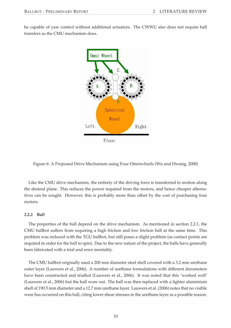
BALLBOT - PRELIMINARY REPORT 2 LITERATURE REVIEW
be capable of yaw control without additional actuators. The CWWU also does not require ball
transfers as the CMU mechanism does.
Figure 6: A Proposed Drive Mechanism using Four Omniwheels (Wu and Hwang, 2008)
Like the CMU drive mechanism, the entirety of the driving force is transferred to motion along
the desired plane. This reduces the power required from the motors, and hence cheaper alterna-
tives can be sought. However, this is probably more than offset by the cost of purchasing four
motors.
2.2.2 Ball
The properties of the ball depend on the drive mechanism. As mentioned in section 2.2.1, the
CMU ballbot suffers from requiring a high friction and low friction ball at the same time. This
problem was reduced with the TGU ballbot, but still poses a slight problem (as contact points are
required in order for the ball to spin). Due to the new nature of the project, the balls have generally
been fabricated with a trial and error mentality.
The CMU ballbot originally used a 200 mm diameter steel shell covered with a 3.2 mm urethane
outer layer (Lauwers et al., 2006). A number of urethane formulations with different durometers
have been constructed and trialled (Lauwers et al., 2006). It was noted that this ‘worked well’
(Lauwers et al., 2006) but the ball wore out. The ball was then replaced with a lighter aluminium
shell of 190.5 mm diameter and a 12.7 mm urethane layer. Lauwers et al. (2006) notes that no visible
wear has occurred on this ball, citing lower shear stresses in the urethane layer as a possible reason.
10
BALLBOT - PRELIMINARY REPORT 2 LITERATURE REVIEW
It is likely that this would have increased the damping in the system, although no comment on its
effect on the performance of the ballbot has been found.
The TGU ballbot uses a bowling ball which is covered in rubber to increase grip (Kumagai and
Ochiai, 2008). A basketball was initially trialled in the TGU ballbot, and, although it could maintain
balance, the it was unsteady (Kumagai and Ochiai, 2008). The rubber-coated bowling ball was used
as it was more rigid and provided better performance.
The properties of the ball used in the ballbot depends greatly on the drive mechanism, and thus
the two constructed ballbot have two very different balls.
2.2.3 Tilt Sensors
In order to be dynamically stable, the ballbot must actuate the ball such that it is driven in
the correct direction to remain upright. Sensors are therefore required to measure the tilt of the
ballbot’s body. However, errors in the measured state exist when only one sensor is used due
to sensor limitations. CMU and TGU ballbots employ similar solutions to this problem in their
measurement of body tilt and angular velocity.
Gyroscopes and accelerometers can be used to measure body tilt. Gyroscopes are used to mea-
sure the angular velocity. However, due to the integration of an angular velocity measurement,
a ‘drifting’ of the angle measurement can occur if an offset exists in the angular velocity mea-
surement. Accelerometers can be used to measure the angle directly by using the direction of
acceleration due to gravity. However, this assumes that no other acceleration is present, and thus
any vibrations within the frame can cause the sensors to give incorrect readings.
The solutions to this problem on the CMU and TGU ballbots are similar. The TGU ballbot uses
ADXRS401 gyroscopes and ADXL203 accelerometers, and uses a first-order digital filter to com-
bine the signals from these two sensors - using the gyroscope signal for high frequency signals and
the accelerometer signal for low frequency signals (Kumagai and Ochiai, 2008). The CMU ballbot
uses an ‘all-in-one’ solution, with a Crossbow Technology VG700CA-200 Inertial Measuring Unit
(IMU) (Lauwers et al., 2006). This unit contains both accelerometers and gyroscopes and provides
a Kalman-filtered pitch and roll angles.
2.2.4 Controller Hardware
Due to the limited functionality of the existing ballbots, minimal processing power is required
for the ballbot. As such, simple microcontrollers are suitable for use as the main controller on the
ballbot. This can be seen in the TGU ballbot, which utilises a Renesas H8/3052 microcontroller
(Kumagai and Ochiai, 2008). This microcontroller has 16-bit registers and a maximum clock rate of
25 MHz (Hitachi, 2001). It is a simple microcontroller which can be easily interfaced with the sen-
sors and actuators used in the ballbot. In comparison, the processing power of the CMU ballbot is
provided with a 200 MHz Pentium processor (Lauwers et al., 2006). This provides more processing
power, and is capable of further functionality to be added to the ballbot.
11
BALLBOT - PRELIMINARY REPORT 2 LITERATURE REVIEW
2.3 Theoretical Controller
A variety of different approaches have been taken in the control of ballbot systems. As discussed
in Section 2.1, the Ballbot system is a non-linear system. The control systems on the two existing
ballbots (CMU and TGU) have both approximated the system as linear, and thus been able to use
linear controllers. Only one other non-linear method of control for a ballbot is discussed, that of
Sliding-Mode Control.
The ballbot system can also be approximated by two independent inverted pendulum systems,
one for each plane. As such, these approaches can be translated to the Ballbot system. For this
project, due to the use of a Lego Mindstorms kit, a controller of interest was that of the NXTway-
GS, a two-wheeled self-balancing robot system. A review of this controller was undertaken due to
its relevance to the project.
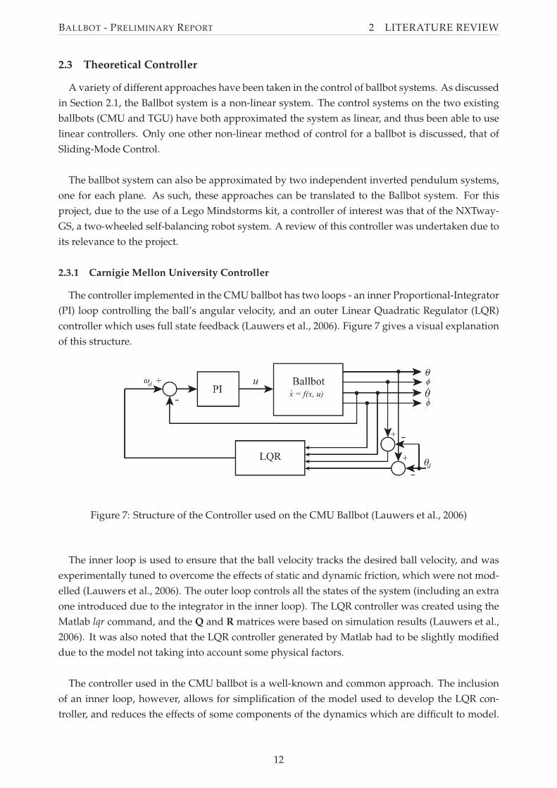
2.3.1 Carnigie Mellon University Controller
The controller implemented in the CMU ballbot has two loops - an inner Proportional-Integrator
(PI) loop controlling the ball’s angular velocity, and an outer Linear Quadratic Regulator (LQR)
controller which uses full state feedback (Lauwers et al., 2006). Figure 7 gives a visual explanation
of this structure.
Figure 7: Structure of the Controller used on the CMU Ballbot (Lauwers et al., 2006)
The inner loop is used to ensure that the ball velocity tracks the desired ball velocity, and was
experimentally tuned to overcome the effects of static and dynamic friction, which were not mod-
elled (Lauwers et al., 2006). The outer loop controls all the states of the system (including an extra
one introduced due to the integrator in the inner loop). The LQR controller was created using the
Matlab lqr command, and the Q and R matrices were based on simulation results (Lauwers et al.,
2006). It was also noted that the LQR controller generated by Matlab had to be slightly modified
due to the model not taking into account some physical factors.
The controller used in the CMU ballbot is a well-known and common approach. The inclusion
of an inner loop, however, allows for simplification of the model used to develop the LQR con-
troller, and reduces the effects of some components of the dynamics which are difficult to model.
12
BALLBOT - PRELIMINARY REPORT 2 LITERATURE REVIEW
Although it is simply a linear controller, it is apparent that this is sufficient to stabilise the ballbot,
based on performance of the physical ballbot.
2.3.2 Tohoku Gakuin University Controller
The Tohoku Gakuin University ballbot uses a simple Proportional-Derivative (PD) controller to
balance. Due to the unusual arrangement of the drive mechanism (discussed in Section 2.2.1, the
controller does not control the wheels directly, but instead controls two ’virtual’ motors, based in
the planes in which the sensors lie, in a similar arrangement to that of the CMU ballbot (Kumagai
and Ochiai, 2008). Kumagai and Ochiai (2008) indicate that the equations used in the controller are
as follows:
(8)ax = KAθx + KAV θx + KT(x − x0) + KVvx
(9)ay = KAθy + KAV θy + KT(y − y0) + KVvy
The proportional gains, KA and KT, and the derivative gains, KAV and KV , were all experimen-
tally derived (Kumagai and Ochiai, 2008). Additionally, Kumagai and Ochiai (2008) note that the
commands are acceleration, as opposed to conventional inverted pendulum systems which use
torque as the command. This is due to the fact that stepper motors are used.
This controller is also very simple and linear in nature. Once again, based on the performance
of the physical ballbot, it is evident that the controller is suitable. It is possible that this simpler
control method is effective due to the properties of the ballbot, including less damping on the ball.
Thus, although the construction and drive mechanism is more complicated, a simple mathematical
relationship is used to convert between the virtual wheels and the physical wheels, resulting in a
controller which is simple at its core, and a mechanical design which is easier to model.
2.3.3 Sliding-Mode Control
A Sliding-Mode Controller for the ballbot system was proposed by Liao et al. (2008) . This con-
troller is designed for the inverse mouse-ball drive used in the CMU ballbot (discussed in sec-
tion 2.2.1), however has not been implemented or tested in a physical ballbot.
Liao et al. (2008) concludes with simulation examples of the sliding-mode controller that this
method is capable of controlling and stabilising a ballbot. However, it is difficult to determine
how this compares to existing linear-decoupled controllers due to the lack of vigorous testing, and
simplistic and single-test approach taken with the simulations.
2.3.4 NXTway-GS Controller
The development of a model-based controller for a the NXTway-GS, a two-wheeled self-balancing
robot built with Lego Mindstorms components, is documented by Yamamoto (2008). At the core
of the controller used in the NXTway-GS is an LQR controller. However, a second loop is also used
for the controller, in order to introduce integral control. The integrator is required in order to use
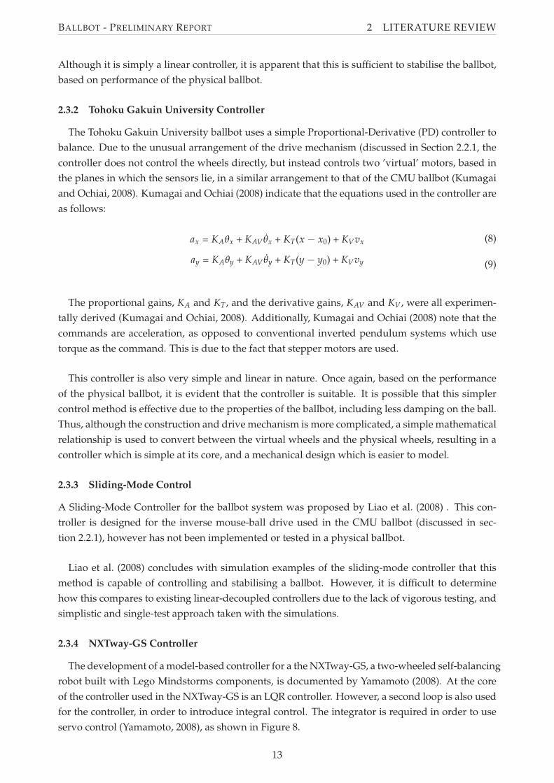
servo control (Yamamoto, 2008), as shown in Figure 8.
13
BALLBOT - PRELIMINARY REPORT 2 LITERATURE REVIEW
Figure 8: Structure of the Controller used in the NXTway-GS (Yamamoto, 2008)
Similar to the CMU ballbot, the Matlab lqr command is used to generate the gains for the con-
troller. Once again, this is a well-known technique, which appears to work adequately well on the
NXTway-GS two-wheeled self-balancing robot.
14
BALLBOT - PRELIMINARY REPORT 3 EQUATIONS OF MOTION
3 Equations of Motion
In order to control a Ballbot, the equations of motion of the system are required. The equations
of motion of the ballbot have been previously derived and documented by Lauwers et al. (2006,
2005) and Liao et al. (2008). However, it is still desirable to derive the dynamics for this case in
order to overcome some of the limitations of the previous work, and also to provide a qualita-
tive understanding of the ballbot dynamics. Furthermore the dynamics are necessary when using
model based control techniques to derive feedback gains, and allow for simulation.
The aim of this section is to derive the dynamics in a form which may be used as a basis for
controller design. This initially involves making assumptions in order to create a simplified ballbot
model in one plane upon which the dynamics can be derived. Following this, the Lagrangian
approach is used to derive the equations of motion of the simplified model. These equations are
linearised and written in a form which can be used for controller design. Finally, the complete
linear model of the Ballbot dynamics is determined.
3.1 Assumptions and Definitions
The equations of motion are derived using a simplified Ballbot model as discussed in Sec-
tion 2.1.1. This model is based on the following assumptions:
• the Ballbot is comprised of two parts; a rigid body atop a rigid ball
• the control torques are applied between the body and the ball
• motion is decoupled in the pitch and roll planes, and that the equations of motion are identi-
cal in these planes
• only viscous friction is considered
• there is no slip
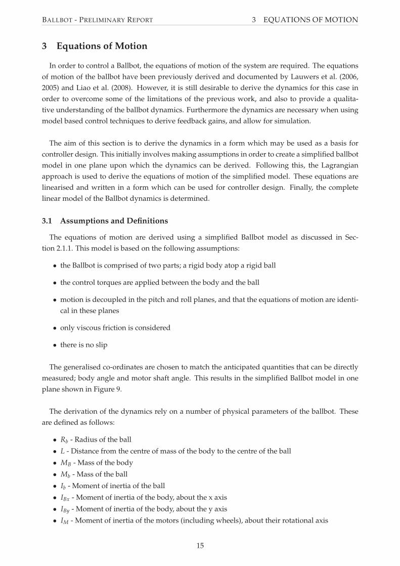
The generalised co-ordinates are chosen to match the anticipated quantities that can be directly
measured; body angle and motor shaft angle. This results in the simplified Ballbot model in one
plane shown in Figure 9.
The derivation of the dynamics rely on a number of physical parameters of the ballbot. These
are defined as follows:
• Rb - Radius of the ball
• L - Distance from the centre of mass of the body to the centre of the ball
• MB - Mass of the body
• Mb - Mass of the ball
• Ib - Moment of inertia of the ball
• IBx - Moment of inertia of the body, about the x axis
• IBy - Moment of inertia of the body, about the y axis
• IM - Moment of inertia of the motors (including wheels), about their rotational axis
15
BALLBOT - PRELIMINARY REPORT 3 EQUATIONS OF MOTION
Figure 9: The Simplified Ballbot Model
• n - Gear ratio, motor to ball, including direction
• µBb - Friction coefficient between body and ball
• µBg - Friction coefficient between body and ground
• Kb - Back EMF constant of motors
• Kt - Torque constant of motors
• Rm - Resistance of the motors
3.2 Derivation
The equations of motion of the simplified Ballbot model in one plane are derived in Matlab using
the Lagrangian approach as discussed in Section 2.1.2. The code used can be seen in Appendix A.
As per the assumptions, only the equations of motion of one plane (x-z) are derived and then the
other plane (y-z) is assumed to have identical dynamics.
The derivation using the Lagrangian approach begins by determining the kinetic and potential
energy of each of the ball, body and motors, as follows:
The Ball:
Table 1: Generalised Coordinate Relationships: Ball
Position Velocity
Angle θx + nφx Angular velocity θx + nφx
x position, xb Rb(θx + nφx) x velocity, xb Rb(θx + nφx)
z position, zb 0 z velocity, zb 0
16

BALLBOT - PRELIMINARY REPORT 3 EQUATIONS OF MOTION
Linear Kinetic Energy of the Ball, Tlinb =
(10)Mb Rb2(
θx + n φx
)2
2
Rotational Kinetic Energy of the Ball, Trotb =
(11)Ib
(
θx + n φx
)2
2
Potential Energy of the Ball, Vb = 0
The Body:
Table 2: Generalised Coordinate Relationships: Body
Position Velocity
Angle θx Angular Velocity θx
x position, xB xb + L sin(θx) x velocity, xB xb + L cos(θx)θx
z position, zB L cos(θx) z velocity, zB −L sin(θx)θx
Linear Kinetic Energy of the Body, TlinB =
(12)MB
(
L2 θx2
+ 2 cos(θx) L n Rb φx θx + 2 cos(θx) L Rb θx2
+ n2 Rb2 φx
2+ 2 n Rb
2 φx θx + Rb2 θx
2)
2
Rotational Kinetic Energy of the Body, TrotB =
(13)IBx θx2
2
Potential Energy of the Body, VB=
(14)g L MB cos(θx)
The Motors:
Table 3: Generalised Coordinate Relationships: Motors
Position Velocity
Angle θx + φx Angular velocity θx + φx
Rotational Kinetic Energy of the Motors, Trotm =
(15)IM
(
φx + θx
)2
2
17
BALLBOT - PRELIMINARY REPORT 3 EQUATIONS OF MOTION
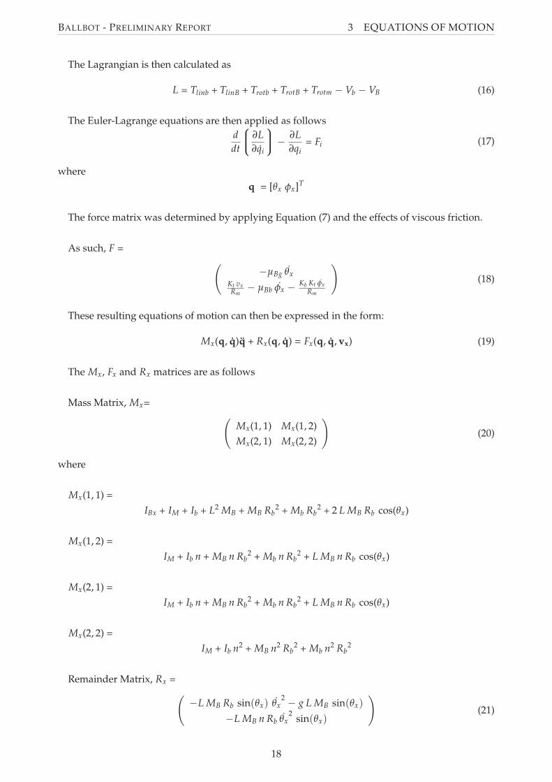
The Lagrangian is then calculated as
(16)L = Tlinb + TlinB + Trotb + TrotB + Trotm − Vb − VB
The Euler-Lagrange equations are then applied as follows
(17)d
dt
∂L
∂qi
−∂L
∂qi= Fi
where
q = [θx φx]T
The force matrix was determined by applying Equation (7) and the effects of viscous friction.
As such, F =
(18)
(
−µBg θx
Kt vxRm
− µBb φx −Kb Kt φx
Rm
)
These resulting equations of motion can then be expressed in the form:
(19)Mx(q, q)q + Rx(q, q) = Fx(q, q, vx)
The Mx, Fx and Rx matrices are as follows
Mass Matrix, Mx=
(20)
(
Mx(1, 1) Mx(1, 2)
Mx(2, 1) Mx(2, 2)
)
where
Mx(1, 1) =
IBx + IM + Ib + L2 MB + MB Rb2 + Mb Rb
2 + 2 L MB Rb cos(θx)
Mx(1, 2) =
IM + Ib n + MB n Rb2 + Mb n Rb
2 + L MB n Rb cos(θx)
Mx(2, 1) =
IM + Ib n + MB n Rb2 + Mb n Rb
2 + L MB n Rb cos(θx)
Mx(2, 2) =
IM + Ib n2 + MB n2 Rb2 + Mb n2 Rb
2
Remainder Matrix, Rx =
(21)
(
−L MB Rb sin(θx) θx2− g L MB sin(θx)
−L MB n Rb θx2
sin(θx)
)
18
BALLBOT - PRELIMINARY REPORT 3 EQUATIONS OF MOTION
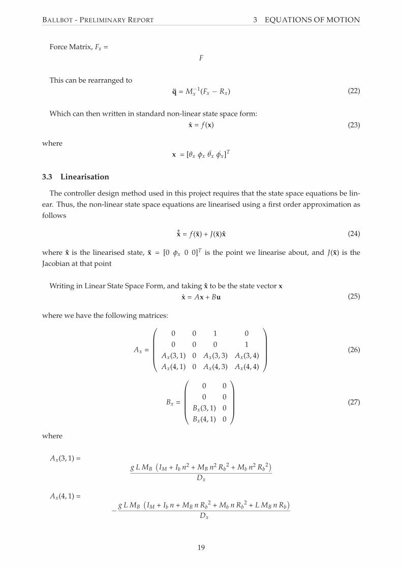
Force Matrix, Fx =
F
This can be rearranged to
(22)q = M−1x (Fx − Rx)
Which can then written in standard non-linear state space form:
(23)x = f (x)
where
x = [θx φx θx φx]T
3.3 Linearisation
The controller design method used in this project requires that the state space equations be lin-
ear. Thus, the non-linear state space equations are linearised using a first order approximation as
follows
(24)ˆx = f (x) + J(x)x
where x is the linearised state, x = [0 φx 0 0]T is the point we linearise about, and J(x) is the
Jacobian at that point
Writing in Linear State Space Form, and taking x to be the state vector x
(25)x = Ax + Bu
where we have the following matrices:
(26)Ax =
0 0 1 0
0 0 0 1
Ax(3, 1) 0 Ax(3, 3) Ax(3, 4)
Ax(4, 1) 0 Ax(4, 3) Ax(4, 4)
(27)Bx =
0 0
0 0
Bx(3, 1) 0
Bx(4, 1) 0
where
Ax(3, 1) =g L MB
(
IM + Ib n2 + MB n2 Rb2 + Mb n2 Rb
2)
Dx
Ax(4, 1) =
−g L MB
(
IM + Ib n + MB n Rb2 + Mb n Rb
2 + L MB n Rb
)
Dx
19
BALLBOT - PRELIMINARY REPORT 3 EQUATIONS OF MOTION
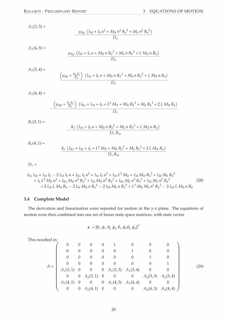
Ax(3, 3) =
−µBg
(
IM + Ib n2 + MB n2 Rb2 + Mb n2 Rb
2)
Dx
Ax(4, 3) =µBg
(
IM + Ib n + MB n Rb2 + Mb n Rb
2 + L MB n Rb
)
Dx
Ax(3, 4) =(
µBb + Kb Kt
Rm
)
(
IM + Ib n + MB n Rb2 + Mb n Rb
2 + L MB n Rb
)
Dx
Ax(4, 4) =
−
(
µBb + Kb Kt
Rm
)
(
IBx + IM + Ib + L2 MB + MB Rb2 + Mb Rb
2 + 2 L MB Rb
)
Dx
Bx(3, 1) =
−Kt
(
IM + Ib n + MB n Rb2 + Mb n Rb
2 + L MB n Rb
)
Dx Rm
Bx(4, 1) =Kt
(
IBx + IM + Ib + L2 MB + MB Rb2 + Mb Rb
2 + 2 L MB Rb
)
Dx Rm
Dx =
(28)
IBx IM + IM Ib − 2 IM Ib n + IBx Ib n2 + IM Ib n2 + IM L2 MB + IM MB Rb2 + IM Mb Rb
2
+ Ib L2 MB n2 + IBx MB n2 Rb2 + IM MB n2 Rb
2 + IBx Mb n2 Rb2 + IM Mb n2 Rb
2
+ 2 IM L MB Rb − 2 IM MB n Rb2− 2 IM Mb n Rb
2 + L2 MB Mb n2 Rb2− 2 IM L MB n Rb
3.4 Complete Model
The derivation and linearisation were repeated for motion in the y-z plane. The equations of
motion were then combined into one set of linear state space matrices, with state vector
x = [θx φx θy φy θx φx θy φy]T
This resulted in:
(29)A =
0 0 0 0 1 0 0 0
0 0 0 0 0 1 0 0
0 0 0 0 0 0 1 0
0 0 0 0 0 0 0 1
Ax(3, 1) 0 0 0 Ax(3, 3) Ax(3, 4) 0 0
0 0 Ay(3, 1) 0 0 0 Ay(3, 3) Ay(3, 4)
Ax(4, 1) 0 0 0 Ax(4, 3) Ax(4, 4) 0 0
0 0 Ay(4, 1) 0 0 0 Ay(4, 3) Ay(4, 4)
20
BALLBOT - PRELIMINARY REPORT 3 EQUATIONS OF MOTION
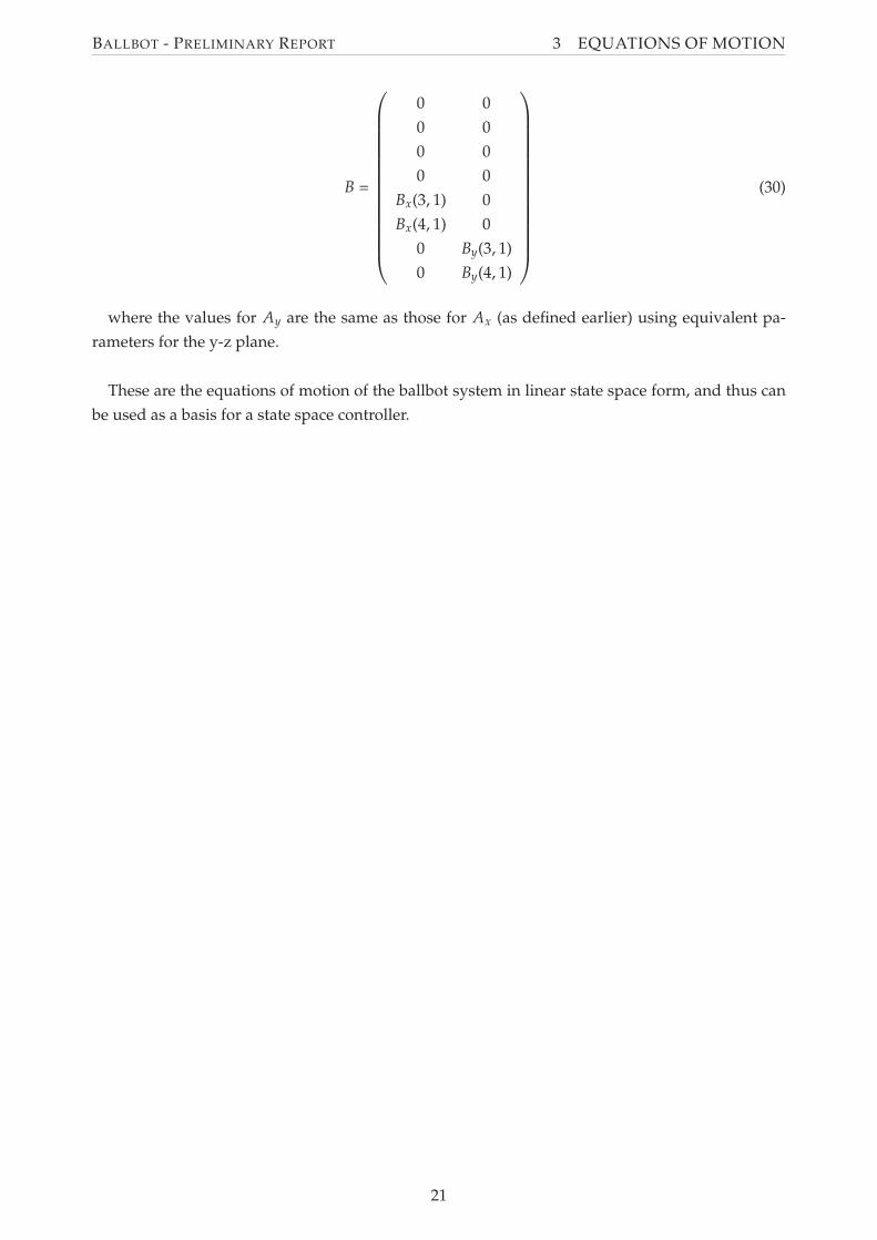
(30)B =
0 0
0 0
0 0
0 0
Bx(3, 1) 0
Bx(4, 1) 0
0 By(3, 1)
0 By(4, 1)
where the values for Ay are the same as those for Ax (as defined earlier) using equivalent pa-
rameters for the y-z plane.
These are the equations of motion of the ballbot system in linear state space form, and thus can
be used as a basis for a state space controller.
21
BALLBOT - PRELIMINARY REPORT 4 THE LEGO BALLBOT
4 The Lego Ballbot
The Lego Ballbot was constructed using the Lego NXT Mindstorms products. The aim of the
construction was to create a Lego Ballbot which could be dynamically stabilised using a controller.
This section begins by describing the parts available in the Lego NXT Mindstorms range, which
may have been used to construct the Lego Ballbot. Following this, the conceptual design of the
Lego Ballbot is discussed, considering the drive mechanism and general layout of the Lego Ballbot.
Finally, the detailed design and construction of the Lego Ballbot is shown.
4.1 Lego NXT Mindstorms Range
The NXT Mindstorms products extend the Lego product range into robotics applications. The
8527 Lego NXT Mindstorms kit is the starter kit for this line of products, and was used for this
project. The parts included in the 8527 kit that are relevant to the construction of the Lego Ballbot
included the NXT Brick, touch sensor, servo motors, and Lego Technic pieces. Additional parts that
are available and may be required for the Lego Ballbot include the HiTechnic gyroscopic sensor,
HiTechnic 3 axis accelerometer, and Lego wheels.
4.1.1 Lego 8527 NXT Mindstorms Kit Included Parts
NXT Brick The NXT Brick is the processor used in the Lego NXT system. The brick is normally
programmed using Lego NXT software provided in the 8527 kit. However, alternative methods
are available including the use of MATLAB’s Simulink Real Time workshop and RobotC. The NXT
Brick has the following specifications (The LEGO Group, 2006):
• Main processor: Atmel 32-bit 48 MHz ARM processor, with 256 KB FLASH and 64 KB RAM
• Co-processor: Atmel 8-bit 8 MHz AVR processor, with 4 KB FLASH and 512 Byte RAM.
• I/O: Four input interfaces, and three output interfaces for servo motors, which also support
input from encoders.
• Power source: 9V (using Alkaline AA batteries or a 1400 mAH rechargeable Lithium-Ion
Battery)
Servos Motors Three 9V DC servo motors are included in the 8527 kit, with built in encoders.
These provide the available actuation system to drive the ball of the Lego Ballbot. The motors
have the following parameters (The LEGO Group, 2006, Yamamoto, 2008, Hurbain, 2009):
• No load characteristics at 9V: Speed = 170 rpm, Current = 60 mA
• Stall characteristics at 9V: Torque = 0.050 Nm, Current = 2A
• Torque Constant Kt = 0.317 N/A
• Back Emf Constant Kb = 0.468 Vs
• Terminal Resistance Rm = 6.69 ohm
• Encoder Resolution: 360 counts per turn (1 degree)
Touch Sensor The touch sensor included in the 8527 kit provides a binary signal to indicate
whether it has been actuated (The LEGO Group, 2006).
22
BALLBOT - PRELIMINARY REPORT 4 THE LEGO BALLBOT
Lego Technic Pieces The 8527 kit contains hundreds of Lego Technic pieces which allowed con-
struction of the Lego Ballbot, including the 52mm diameter ball, frame pieces and various connec-
tion elements. A full parts list can be found in Appendix E.
4.1.2 Possible Additional Required Parts
HiTechnic Gyroscopic sensor The HiTechnic Gyroscopic sensor contains a single axis gyroscope
and can be used to detect rotation in one axis. It measures the rotation in degrees per second up to
a maximum rate of 360 degrees/sec (HiTechnic Products, 2008). This value can be integrated over
time to provide a measure for angle.
HiTechnic 3-Axis Accelerometer The HiTechnic 3-Axis Accelerometer can be used to measure
acceleration in all three axes x, y and z. This also allows the accelerometer to measure tilt by
detecting the direction of acceleration due to gravity. The resolution is approximately 1/200 g
with a range of -2g to +2g (HiTechnic Products, 2008).
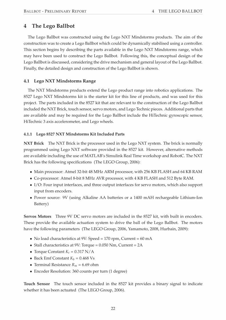
Wheels The only available wheels in the kit have a diameter of 56mm, which was deemed to be
too large for the Lego Ballbot, as they have a larger diameter than the ball (52mm). Thus, other
Lego wheels were considered in the construction of the Lego Ballbot. These are shown in Figure 10
Figure 10: Lego Wheels considered for use in the Lego Ballbot
4.2 Conceptual design
Design of the Lego Ballbot began with conceptual design, which considered the general layout of
the Lego Ballbot and how the required functionality could be implemented. The aim of the concept
design was to provide a design that will be used as a guide for Lego construction process. Firstly,
several possible ball drive mechanism concepts were developed and evaluated. Based upon the
drive mechanism and the anticipated requirements for the controller, the required components of
the Lego Ballbot were determined. Finally, the layout of these parts was considered to form the
design of the Lego Ballbot. The conceptual design did not consider the use of individual Lego
parts, as this was determined during the construction process, described in Section 4.3.1.
4.2.1 Drive Mechanism
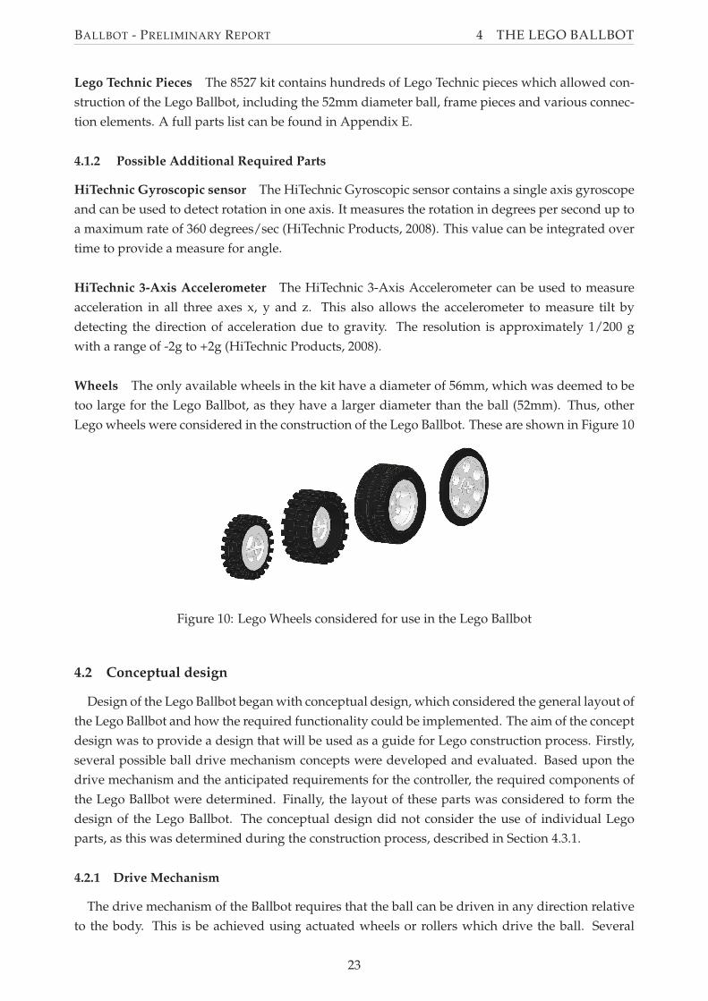
The drive mechanism of the Ballbot requires that the ball can be driven in any direction relative
to the body. This is be achieved using actuated wheels or rollers which drive the ball. Several
23
BALLBOT - PRELIMINARY REPORT 4 THE LEGO BALLBOT
possible arrangements of ball and wheels were considered, and are shown in Figure 11. These
conceptual designs are based on previous works as discussed in Section 2.2.1 and brainstorming.
(1) Orthogonal fixed wheels at ball centre axis,adapted from Lauwers et al. (2006)
(2) Orthogonal omniwheels at ball centre axis
(3) Orthogonal omniwheels above ball centre axis,adapted from Wu and Hwang (2008)
(4) Tri omniwheels above ball centre axis, adaptedfrom Kumagai and Ochiai (2008)
(5) Orthogonal omniwheel pairs above ball centreaxis
Figure 11: Drive mechanism concepts
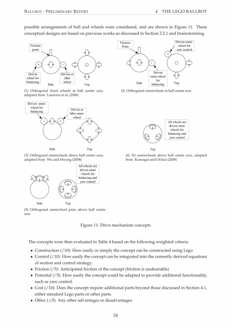
The concepts were then evaluated in Table 4 based on the following weighted criteria:
• Construction (/10): How easily or simply the concept can be constructed using Lego
• Control (/10): How easily the concept can be integrated into the currently derived equations
of motion and control strategy.
• Friction (/5): Anticipated friction of the concept (friction is undesirable)
• Potential (/5): How easily the concept could be adapted to provide additional functionality,
such as yaw control.
• Cost (/10): Does the concept require additional parts beyond those discussed in Section 4.1,
either standard Lego parts or other parts.
• Other (±5): Any other advantages or disadvantages
24
BA
LL
BO
T-
PR
EL
IMIN
AR
YR
EP
OR
T4
TH
EL
EG
OB
AL
LB
OT
Table 4: Decision Matrix for Lego Ballbot Drive MechanismConcept Construction /10 Control /10 Friction /5 Potential /5 Cost /10 Other +-5 Total Score1a (one drivenwheel per pair)
Simple Simple High due to frictionpoint and orthogonalwheels
Low Low Applied actuation is nota pure torque
10 10 0 0 10 -2 281b (all wheelsdriven)
Relatively Simple Some difficulty as pairsof wheels must be syn-chronised
High due to frictionpoint and orthogonalwheels
Low Requires an additionalservo drive (beyondthose included in thekit)
Applied actuation is apure torque
8 8 0 0 6 +2 24
2The use of a non-standard Lego part addsdifficulty. Asymmetriesalso add difficulty
Simple Low due to use of omni-wheels
High - location of om-niwheels will provideyaw control from theball
Requires the use of om-niwheels (non standardLego part)
Applied actuation is nota pure torque
3 10 5 5 4 -2 253a (one drivenwheel per pair)
The use of a non-standard Lego partadds difficulty
Simple Low due to use of omni-wheels
Moderate - use of omni-wheels allow for easieraddition of yaw controlfrom the ball
Requires the use of om-niwheels (non standardLego part)
Applied actuation is nota pure torque
5 10 5 3 4 -2 253b (all wheelsdriven)
The use of a non-standard Lego partadds difficulty
Simple Low due to use of omni-wheels
Moderate - use of omni-wheels allow for easieraddition of yaw controlfrom the ball
Requires a forth servodrive and the use of om-niwheels (non standardLego part)
Applied actuation is nota pure torque (but less-ened)
5 10 5 3 0 -1 22
4The use of a non-standard Lego partadds difficulty. Nonorthogonal and angledwheels adds difficulty
High difficulty as theremust be a conversionbetween orthogonaltorques and the threewheels
Low due to use of omni-wheels
High - location of om-niwheels will provideyaw control from theball
Requires the use of om-niwheels (non standardLego part)
Applied actuation is nota pure torque (but less-ened)
0 4 5 5 4 -1 17
5The use of a non-standard Lego partadds difficulty. Angledwheels add difficulty.
Moderate difficulty aspairs of wheels must besynchronised
Low due to use of omni-wheels
High - location of om-niwheels will provideyaw control from theball
Requires a forth servodrive and the use of om-niwheels (non standardLego part)
Applied actuation is nota pure torque (but less-ened)
3 8 5 5 0 -1 20
25
BALLBOT - PRELIMINARY REPORT 4 THE LEGO BALLBOT
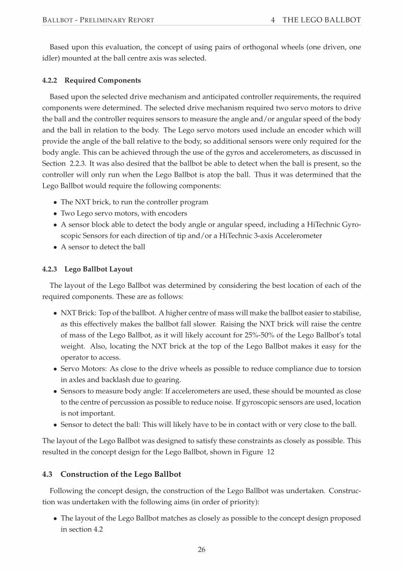
Based upon this evaluation, the concept of using pairs of orthogonal wheels (one driven, one
idler) mounted at the ball centre axis was selected.
4.2.2 Required Components
Based upon the selected drive mechanism and anticipated controller requirements, the required
components were determined. The selected drive mechanism required two servo motors to drive
the ball and the controller requires sensors to measure the angle and/or angular speed of the body
and the ball in relation to the body. The Lego servo motors used include an encoder which will
provide the angle of the ball relative to the body, so additional sensors were only required for the
body angle. This can be achieved through the use of the gyros and accelerometers, as discussed in
Section 2.2.3. It was also desired that the ballbot be able to detect when the ball is present, so the
controller will only run when the Lego Ballbot is atop the ball. Thus it was determined that the
Lego Ballbot would require the following components:
• The NXT brick, to run the controller program
• Two Lego servo motors, with encoders
• A sensor block able to detect the body angle or angular speed, including a HiTechnic Gyro-
scopic Sensors for each direction of tip and/or a HiTechnic 3-axis Accelerometer
• A sensor to detect the ball
4.2.3 Lego Ballbot Layout
The layout of the Lego Ballbot was determined by considering the best location of each of the
required components. These are as follows:
• NXT Brick: Top of the ballbot. A higher centre of mass will make the ballbot easier to stabilise,
as this effectively makes the ballbot fall slower. Raising the NXT brick will raise the centre
of mass of the Lego Ballbot, as it will likely account for 25%-50% of the Lego Ballbot’s total
weight. Also, locating the NXT brick at the top of the Lego Ballbot makes it easy for the
operator to access.
• Servo Motors: As close to the drive wheels as possible to reduce compliance due to torsion
in axles and backlash due to gearing.
• Sensors to measure body angle: If accelerometers are used, these should be mounted as close
to the centre of percussion as possible to reduce noise. If gyroscopic sensors are used, location
is not important.
• Sensor to detect the ball: This will likely have to be in contact with or very close to the ball.
The layout of the Lego Ballbot was designed to satisfy these constraints as closely as possible. This
resulted in the concept design for the Lego Ballbot, shown in Figure 12
4.3 Construction of the Lego Ballbot
Following the concept design, the construction of the Lego Ballbot was undertaken. Construc-
tion was undertaken with the following aims (in order of priority):
• The layout of the Lego Ballbot matches as closely as possible to the concept design proposed
in section 4.2
26
BALLBOT - PRELIMINARY REPORT 4 THE LEGO BALLBOT
Figure 12: Layout of the Lego Ballbot
• The Lego Ballbot, where possible, uses only Lego pieces available in the NXT Mindstorms
kit, or those additional parts identified as necessary in section 4.1.
• The Lego Ballbot is well balanced, ie: the centre of mass of the Ballbot is directly over the
centre of ball when the body is vertical.
• The Lego Ballbot is as rigid as possible, as a flexible structure will result in resonances at low
frequencies.
The construction process used a trial and error iterative approach. This involved attempting to
construct the Lego Ballbot starting with the drive mechanism and working upwards, making mod-
ifications to the previous construction as required due to part availability. The modular nature of
Lego allows this, as the Lego Ballbot could easily be disassembled and reassembled with modifi-
cations at any stage during construction. This process resulted in the original Lego Ballbot. The
original design was further modified during controller development to improve performance.
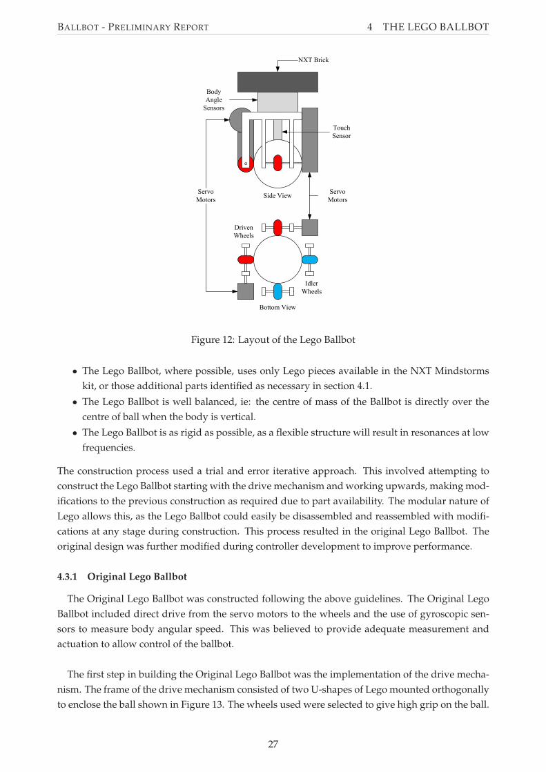
4.3.1 Original Lego Ballbot
The Original Lego Ballbot was constructed following the above guidelines. The Original Lego
Ballbot included direct drive from the servo motors to the wheels and the use of gyroscopic sen-
sors to measure body angular speed. This was believed to provide adequate measurement and
actuation to allow control of the ballbot.
The first step in building the Original Lego Ballbot was the implementation of the drive mecha-
nism. The frame of the drive mechanism consisted of two U-shapes of Lego mounted orthogonally
to enclose the ball shown in Figure 13. The wheels used were selected to give high grip on the ball.
27
BALLBOT - PRELIMINARY REPORT 4 THE LEGO BALLBOT
The servo motors were mounted on opposite corners of this structure. These directly drive two
orthogonal wheels, hence providing two orthogonal torques to the ball.
(a) A Single U-Frame (b) Underneath (c) Complete
Figure 13: Lego Ballbot: The Frame for the Drive Mechanism
The second step involved extending the frame vertically to allow for sensor mounting. The
sensors used on the Original Lego Ballbot included a touch sensor to detect the ball, and gyroscopic
sensors to determine body angle. The touch sensor was mounted vertically in the centre of the
frame, as shown in Figure 14(a). This serves to vertically locate the ball, and also indicate to the
controller that the ball is present. This feature was intended to allow the controller to disable when
the Lego Ballbot is removed from the ball. The gyroscopic sensors are mounted on the frame to
provide measurements in the two planes of body tip as shown in Figure 14(b).
(a) Position of the Touch Sensor (b) Position of Gyroscope Sensors
Figure 14: Lego Ballbot: Sensor Locations
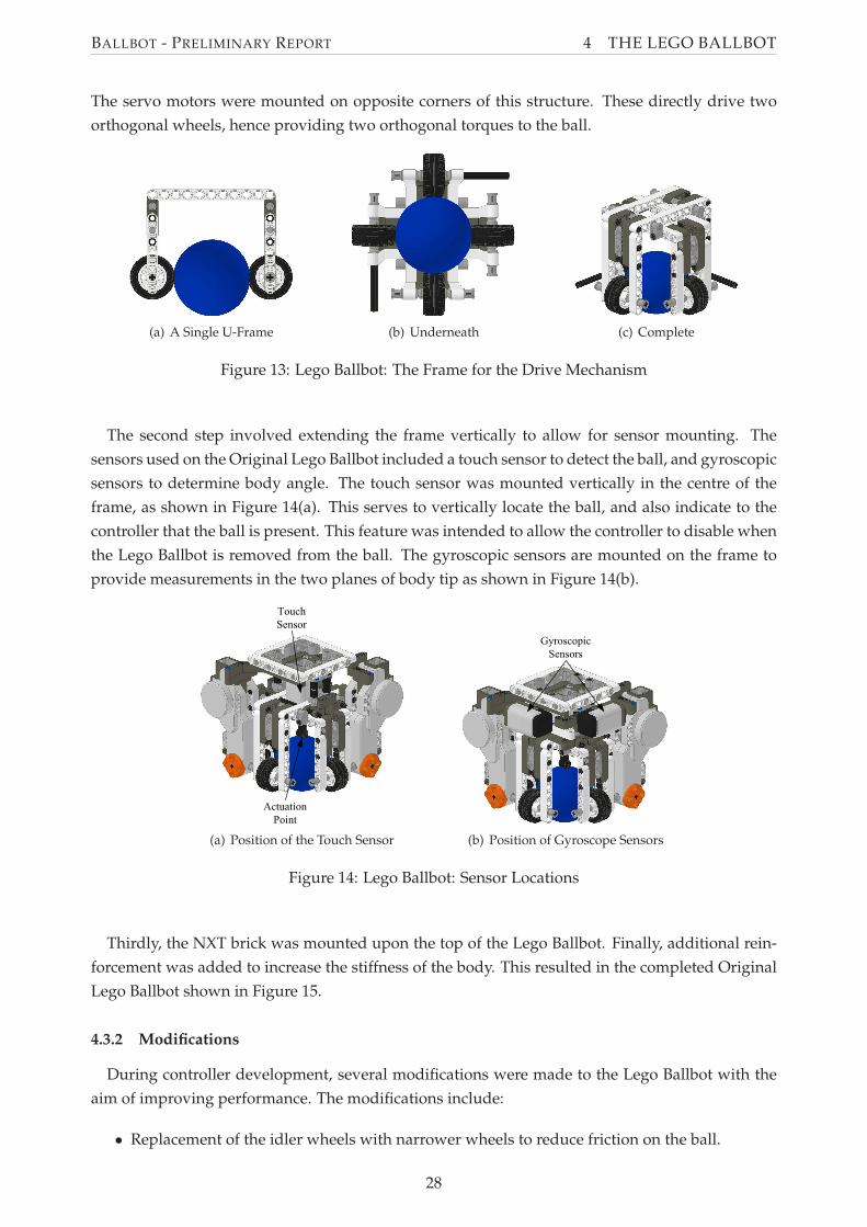
Thirdly, the NXT brick was mounted upon the top of the Lego Ballbot. Finally, additional rein-
forcement was added to increase the stiffness of the body. This resulted in the completed Original
Lego Ballbot shown in Figure 15.
4.3.2 Modifications
During controller development, several modifications were made to the Lego Ballbot with the
aim of improving performance. The modifications include:
• Replacement of the idler wheels with narrower wheels to reduce friction on the ball.
28
BALLBOT - PRELIMINARY REPORT 4 THE LEGO BALLBOT
(a) Front (b) Back
Figure 15: Lego Ballbot: Complete
• The addition of gearing between the servo motors and wheels to increase the maximum
possible ball velocity
• Increasing the height of the centre of mass of the Lego Ballbot by raising the NXT brick. This
aimed to slow the rate at which the ballbot falls over, hence making it easier to control.
• The addition of a 3-axis accelerometer to assist in measuring the body angle, as discussed in
Section 5.3.6.
These modification are shown in Figure 16.
Figure 16: Lego Ballbot: Lego Ballbot Modifications
4.4 Final Lego Ballbot Parameters
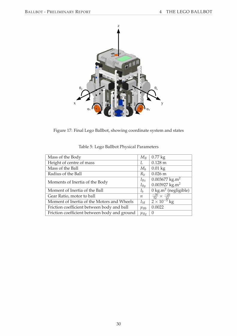
The final Lego Ballbot with states as defined in Section 3 is shown in Figure 17.
29
BALLBOT - PRELIMINARY REPORT 4 THE LEGO BALLBOT
Figure 17: Final Lego Ballbot, showing coordinate system and states
Table 5: Lego Ballbot Physical Parameters
Mass of the Body MB 0.77 kg
Height of centre of mass L 0.128 m
Mass of the Ball Mb 0.01 kg
Radius of the Ball Rb 0.026 m
Moments of Inertia of the BodyIBx 0.003677 kg.m2
IBy 0.003927 kg.m2
Moment of Inertia of the Ball Ib 0 kg.m2 (negligible)
Gear Ratio, motor to ball n −3052 ×
−2012
Moment of Inertia of the Motors and Wheels IM 2 × 10⁻⁵ kg
Friction coefficient between body and ball µBb 0.0022
Friction coefficient between body and ground µBg 0
30
BALLBOT - PRELIMINARY REPORT 5 CONTROLLER
5 Controller
The controller developed for this ballbot project was based on the controller for the NXTway-GS.
This section of the report details the analysis of the NXTway-GS controller for use in this project,
the development of the theoretical controller, simulation of the performance of this theoretical
controller, and the implementation of this theoretical controller into software for use on the NXT
brick.
5.1 Suitability of NXTway-GS Controller Program for Modification
It was decided that the controller for the ballbot project could be created by modifying the
NXTway-GS controller, documented and created by Yamamoto (2008). Two main issues were con-
sidered in assessing the suitability of modifying the NXTway-GS controller for use on the ballbot.
First, the similarities between the two systems were assessed to determine whether the NXTway-
GS controller would require major modification. Secondly, the use of Simulink for programming
was compared to other methods of programming.
The NXTway-GS controller can be modified to be used as the controller in this project. It has
already been established that the ballbot can be modelled as two independent systems of a two-
wheeled self-balancing robot, such as the NXTway-GS. Furthermore, much of the functionality
provided by the NXTway-GS controller is similar to that required for the controller in this project,
including command tracking, the use of the Lego Mindstorms Kit, and the use of the same com-
ponents (gyroscopes and servo motors). The largest fundamental difference between the two pro-
grams is that the ballbot controller will require twice as many states, and thus a large amount of
additional processing power. It was thought, given the relative simplicity of the program, the con-
troller hardware would be able to provide this. This was later confirmed due to the production
of the NXT Ballbot, also created by Yamamoto and based on the NXTway-GS controller. It was
therefore concluded that the differences between the two systems were not significant, and thus
no major modifications of the controller would be required.
The use of Simulink for programming is advantageous for the purposes of this project, due to
the fact that it the program is used in educational classes at the University of Adelaide. The avail-
ability of the ECRobot NXT Blockset for Simulink allows for easy interfacing with the sensors and
actuators used on the Lego Ballbot. The alternate method of programming the Lego Mindstorms
brick is to use the RobotC. This is a programming language based on C, developed for use with
the Lego Mindstorms kit. It was decided that using this method of programming was not as clear
as using the graphical programming language of Simulink, and thus using Simulink would serve
the project better for programming.
Therefore, it was concluded that the NXTway-GS controller would provide a good foundation
on which to base a controller for the project.
31
BALLBOT - PRELIMINARY REPORT 5 CONTROLLER
5.2 Theoretical Controller
A number of controller options were considered for the ballbot, many of which have been dis-
cussed in section 2.3. For this project, a state space controller was selected, with gains calculated
using the Linear Quadratic Regulator (LQR) technique.
The LQR is a well-understood technique, and is taught in control subjects at the University of
Adelaide. In an LQR controller, the control signal is based upon the desired state xref and the actual
state of the system x ie:
u = k(xref − x) = kex
LQR attempts to choose gains which optimise the control signals, based on a heuristic, created
on construction. The significant disadvantage to this approach is that it is often hard to select an
appropriate quantifiable heuristic, and this choice is often superficial. Furthermore, the controller
is only a linear controller, which limits its accuracy when applied to non-linear systems such as the
ballbot. However, it was felt that an LQR controller was an appropriate choice for this system due
to its simplicity and its similarities to the CMU ballbot and NXTway-GS controller, which also use
an LQR controller (Lauwers et al., 2006, Yamamoto, 2008).
The development of a state-space LQR controller requires a linear state space model of the sys-
tem, and the calculation of the controller gains using a heuristic.
5.2.1 State Space Model of the Lego Ballbot
In order to create any controller, knowledge of the system dynamics are required. These dy-
namics were derived using suitable assumptions for a simplified ballbot in Section 3 in the form
of equations of motions. These equations of motion are applied to the Lego Ballbot using the
co-ordinates, states and physical parameters defined in Section 4.4.
The equations of motion are given in state space form x = Ax + Bu where the state vector x
consists of
• θx - The angle of the body of the ballbot relative to the vertical in the x-plane
• φx - The angle of the motor shaft relative to the body in the x-plane
• θy - The angle of the body of the ballbot relative to the vertical in the y-plane
• φy - The angle of the motor shaft relative to the body in the y-plane
• θx - The angular velocity of the body of the ballbot in the x-plane
• φx - The angular velocity of the motor shaft relative to the body in the x-plane
• θy - The angular velocity of the body of the ballbot in the y-plane
• φy - The angular velocity of the motor shaft relative to the body in the y-plane
and the control signal u consists of the two motor voltages.
32
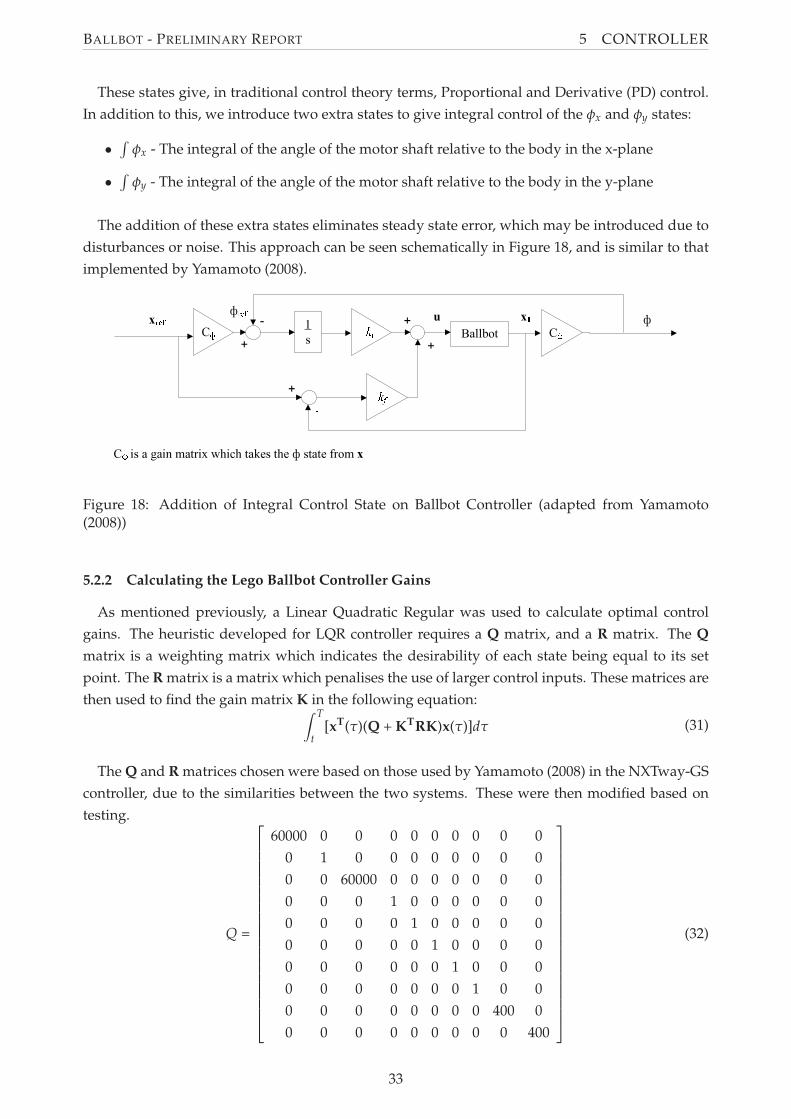
BALLBOT - PRELIMINARY REPORT 5 CONTROLLER
These states give, in traditional control theory terms, Proportional and Derivative (PD) control.
In addition to this, we introduce two extra states to give integral control of the φx and φy states:
•∫
φx - The integral of the angle of the motor shaft relative to the body in the x-plane
•∫
φy - The integral of the angle of the motor shaft relative to the body in the y-plane
The addition of these extra states eliminates steady state error, which may be introduced due to
disturbances or noise. This approach can be seen schematically in Figure 18, and is similar to that
implemented by Yamamoto (2008).
Figure 18: Addition of Integral Control State on Ballbot Controller (adapted from Yamamoto(2008))
5.2.2 Calculating the Lego Ballbot Controller Gains
As mentioned previously, a Linear Quadratic Regular was used to calculate optimal control
gains. The heuristic developed for LQR controller requires a Q matrix, and a R matrix. The Q
matrix is a weighting matrix which indicates the desirability of each state being equal to its set
point. The R matrix is a matrix which penalises the use of larger control inputs. These matrices are
then used to find the gain matrix K in the following equation:
(31)∫ T
t[xT(τ)(Q + KTRK)x(τ)]dτ
The Q and R matrices chosen were based on those used by Yamamoto (2008) in the NXTway-GS
controller, due to the similarities between the two systems. These were then modified based on
testing.
(32)Q =
60000 0 0 0 0 0 0 0 0 0
0 1 0 0 0 0 0 0 0 0
0 0 60000 0 0 0 0 0 0 0
0 0 0 1 0 0 0 0 0 0
0 0 0 0 1 0 0 0 0 0
0 0 0 0 0 1 0 0 0 0
0 0 0 0 0 0 1 0 0 0
0 0 0 0 0 0 0 1 0 0
0 0 0 0 0 0 0 0 400 0
0 0 0 0 0 0 0 0 0 400
33
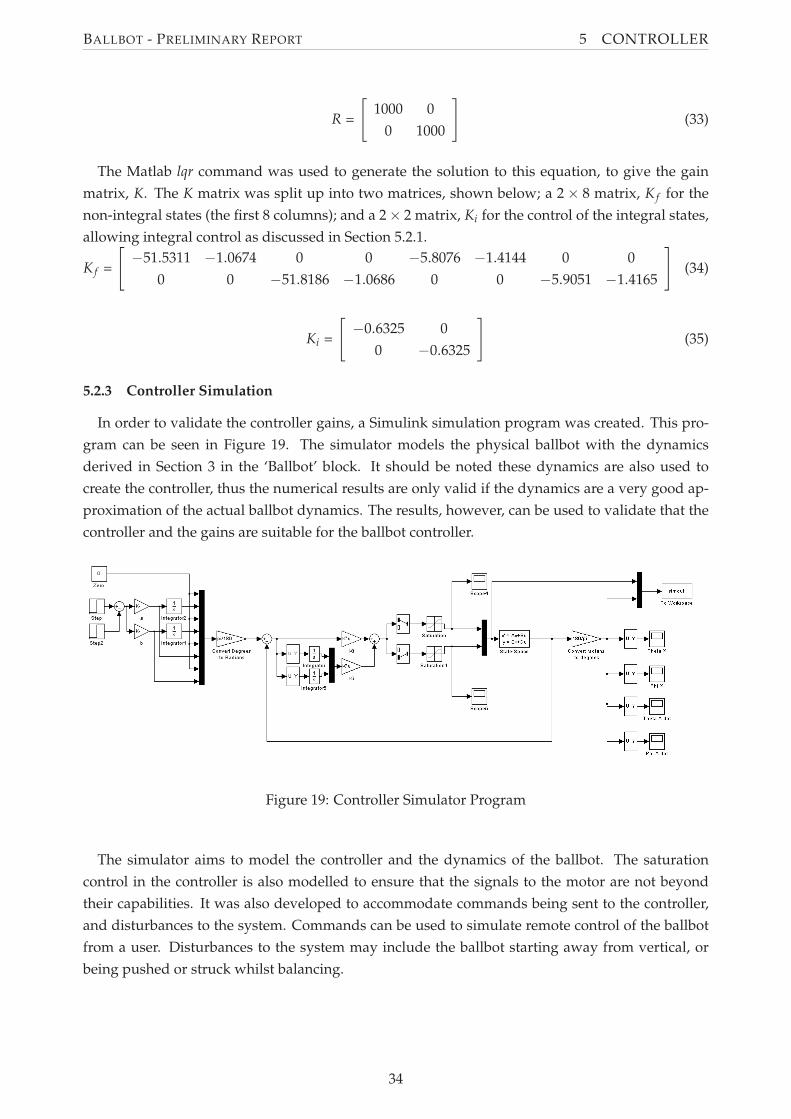
BALLBOT - PRELIMINARY REPORT 5 CONTROLLER
(33)R =
[
1000 0
0 1000
]
The Matlab lqr command was used to generate the solution to this equation, to give the gain
matrix, K. The K matrix was split up into two matrices, shown below; a 2 × 8 matrix, K f for the
non-integral states (the first 8 columns); and a 2 × 2 matrix, Ki for the control of the integral states,
allowing integral control as discussed in Section 5.2.1.
(34)K f =
[
−51.5311 −1.0674 0 0 −5.8076 −1.4144 0 0
0 0 −51.8186 −1.0686 0 0 −5.9051 −1.4165
]
(35)Ki =
[
−0.6325 0
0 −0.6325
]
5.2.3 Controller Simulation
In order to validate the controller gains, a Simulink simulation program was created. This pro-
gram can be seen in Figure 19. The simulator models the physical ballbot with the dynamics
derived in Section 3 in the ‘Ballbot’ block. It should be noted these dynamics are also used to
create the controller, thus the numerical results are only valid if the dynamics are a very good ap-
proximation of the actual ballbot dynamics. The results, however, can be used to validate that the
controller and the gains are suitable for the ballbot controller.
Figure 19: Controller Simulator Program
The simulator aims to model the controller and the dynamics of the ballbot. The saturation
control in the controller is also modelled to ensure that the signals to the motor are not beyond
their capabilities. It was also developed to accommodate commands being sent to the controller,
and disturbances to the system. Commands can be used to simulate remote control of the ballbot
from a user. Disturbances to the system may include the ballbot starting away from vertical, or
being pushed or struck whilst balancing.
34
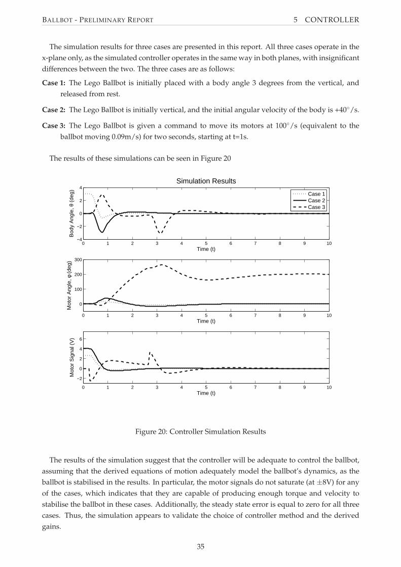
BALLBOT - PRELIMINARY REPORT 5 CONTROLLER
The simulation results for three cases are presented in this report. All three cases operate in the
x-plane only, as the simulated controller operates in the same way in both planes, with insignificant
differences between the two. The three cases are as follows:
Case 1: The Lego Ballbot is initially placed with a body angle 3 degrees from the vertical, and
released from rest.
Case 2: The Lego Ballbot is initially vertical, and the initial angular velocity of the body is +40◦/s.
Case 3: The Lego Ballbot is given a command to move its motors at 100◦/s (equivalent to the
ballbot moving 0.09m/s) for two seconds, starting at t=1s.
The results of these simulations can be seen in Figure 20
0 1 2 3 4 5 6 7 8 9 10−4
−2
0
2
4Simulation Results
Time (t)
Bod
y A
ngle
, θ (
deg)
0 1 2 3 4 5 6 7 8 9 10
0
100
200
300
Time (t)
Mot
or A
ngle
, φ (
deg)
0 1 2 3 4 5 6 7 8 9 10
−2
0
2
4
6
Time (t)
Mot
or S
igna
l (V
)
Case 1Case 2Case 3
Figure 20: Controller Simulation Results
The results of the simulation suggest that the controller will be adequate to control the ballbot,
assuming that the derived equations of motion adequately model the ballbot’s dynamics, as the
ballbot is stabilised in the results. In particular, the motor signals do not saturate (at ±8V) for any
of the cases, which indicates that they are capable of producing enough torque and velocity to
stabilise the ballbot in these cases. Additionally, the steady state error is equal to zero for all three
cases. Thus, the simulation appears to validate the choice of controller method and the derived
gains.
35
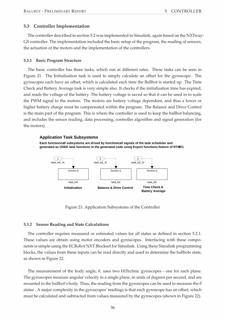
BALLBOT - PRELIMINARY REPORT 5 CONTROLLER
5.3 Controller Implementation
The controller described in section 5.2 was implemented in Simulink, again based on the NXTway-
GS controller. The implementation included the basic setup of the program, the reading of sensors,
the actuation of the motors and the implementation of the controllers.
5.3.1 Basic Program Structure
The basic controller has three tasks, which run at different rates. These tasks can be seen in
Figure 21. The Initialisation task is used to simply calculate an offset for the gyroscope. The
gyroscopes each have an offset, which is calculated each time the Ballbot is started up. The Time
Check and Battery Average task is very simple also. It checks if the initialisation time has expired,
and reads the voltage of the battery. The battery voltage is saved so that it can be used in to scale
the PWM signal to the motors. The motors are battery voltage dependent, and thus a lower or
higher battery charge must be compensated within the program. The Balance and Drive Control
is the main part of the program. This is where the controller is used to keep the ballbot balancing,
and includes the sensor reading, data processing, controller algorithm and signal generation (for
the motors).
Application Task SubsystemsEach function−call subsystems are drived by function−call signals of the task scheduler andgenerated as OSEK task functions in the generated code using Export functions feature of RTW−EC.
Initialization Balance & Drive Control Time Check &Battery Average
task_ts2
function ()
task_ts1
function ()
task_init
function ()
task_ts2_fc
3
task_ts1_fc
2
task_init _fc
1
Figure 21: Application Subsystems of the Controller
5.3.2 Sensor Reading and State Calculations
The controller requires measured or estimated values for all states as defined in section 5.2.1.
These values are obtain using motor encoders and gyroscopes. Interfacing with these compo-
nents is simple using the ECRobot NXT Blockset for Simulink. Using these Simulink programming
blocks, the values from these inputs can be read directly and used to determine the ballbots state,
as shown in Figure 22.
The measurement of the body angle, θ, uses two HiTechnic gyroscopes - one for each plane.
The gyroscopes measure angular velocity in a single plane, in units of degrees per second, and are
mounted to the ballbot’s body. Thus, the reading from the gyroscopes can be used to measure the θ
states . A major complexity in the gyroscopes’ readings is that each gyroscope has an offset, which
must be calculated and subtracted from values measured by the gyroscopes (shown in Figure 22).
36
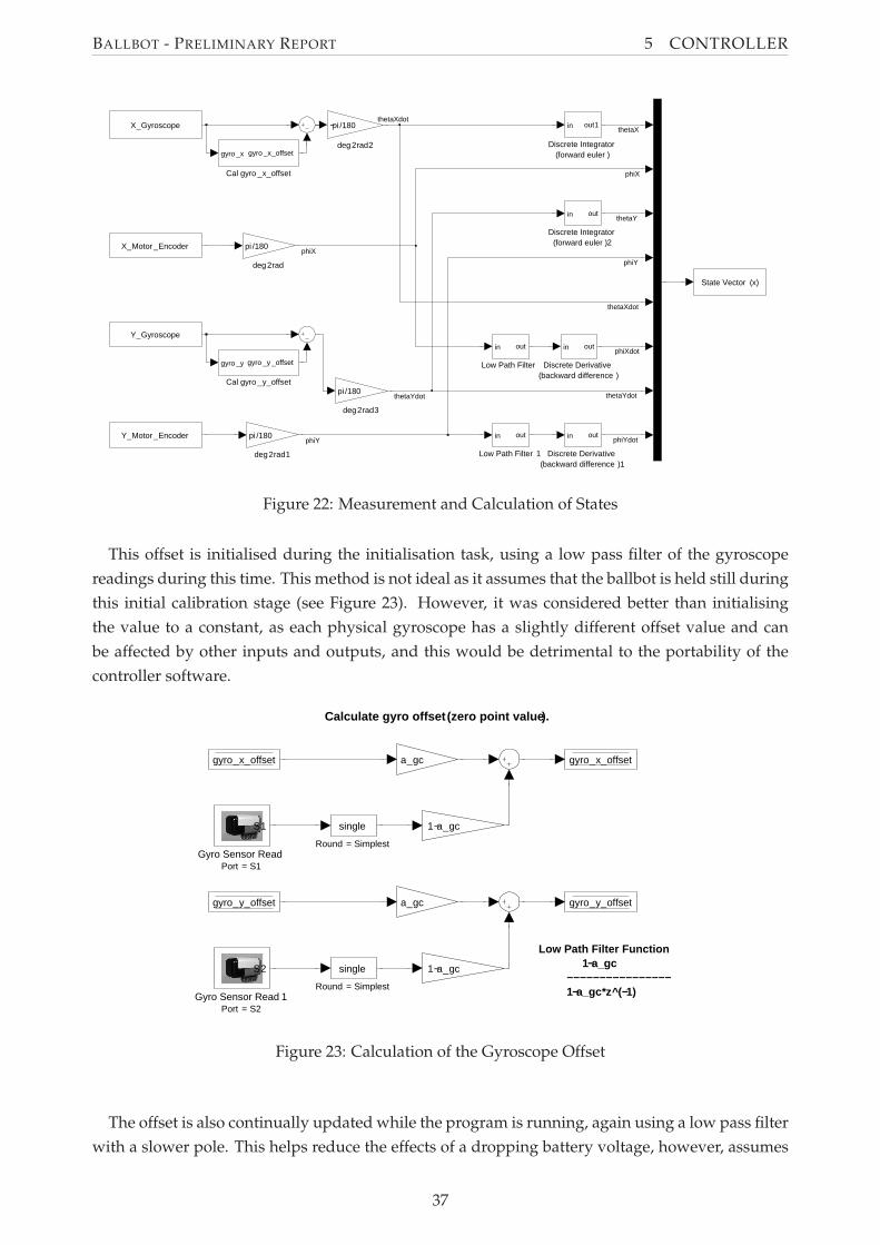
BALLBOT - PRELIMINARY REPORT 5 CONTROLLER
deg2rad3
pi /180
deg2rad2
−pi /180
deg2rad1
pi /180
deg2rad
pi /180
Low Path Filter 1
in out
Low Path Filter
in out
Discrete Integrator(forward euler )2
in out
Discrete Integrator(forward euler )
in out1
Discrete Derivative(backward difference )1
in out
Discrete Derivative(backward difference )
in out
Cal gyro _y_offset
gyro _y gyro _y _offset
Cal gyro _x_offset
gyro _x gyro _x_offset
X_Gyroscope
Y_Motor _Encoder
X_Motor _Encoder
Y_Gyroscope
State Vector (x)
thetaX
thetaXdot
thetaXdot
phiX
phiX
thetaY
thetaYdotthetaYdot
phiY
phiY
phiXdot
phiYdot
Figure 22: Measurement and Calculation of States
This offset is initialised during the initialisation task, using a low pass filter of the gyroscope
readings during this time. This method is not ideal as it assumes that the ballbot is held still during
this initial calibration stage (see Figure 23). However, it was considered better than initialising
the value to a constant, as each physical gyroscope has a slightly different offset value and can
be affected by other inputs and outputs, and this would be detrimental to the portability of the
controller software.
Low Path Filter Function 1−a_gc −−−−−−−−−−−−−−−− 1−a_gc*z^(−1)
Calculate gyro offset (zero point value).
Gyro Sensor Read 1Port = S2
S2
Gyro Sensor ReadPort = S1
S1
a_gc
a_gc
1−a_gc
1−a_gc
Round = Simplest
single
Round = Simplest
single
gyro_y_offset
gyro_x_offsetgyro_x_offset
gyro_y_offset
Figure 23: Calculation of the Gyroscope Offset
The offset is also continually updated while the program is running, again using a low pass filter
with a slower pole. This helps reduce the effects of a dropping battery voltage, however, assumes
37
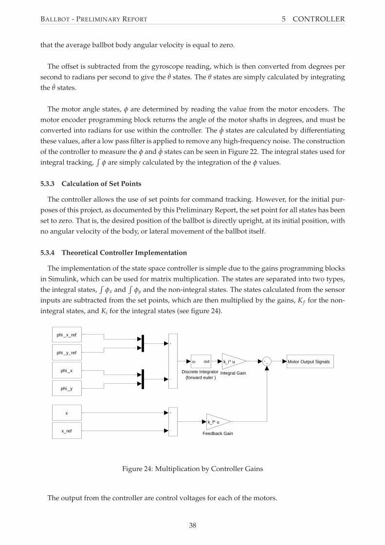
BALLBOT - PRELIMINARY REPORT 5 CONTROLLER
that the average ballbot body angular velocity is equal to zero.
The offset is subtracted from the gyroscope reading, which is then converted from degrees per
second to radians per second to give the θ states. The θ states are simply calculated by integrating
the θ states.
The motor angle states, φ are determined by reading the value from the motor encoders. The
motor encoder programming block returns the angle of the motor shafts in degrees, and must be
converted into radians for use within the controller. The φ states are calculated by differentiating
these values, after a low pass filter is applied to remove any high-frequency noise. The construction
of the controller to measure the φ and φ states can be seen in Figure 22. The integral states used for
integral tracking,∫
φ are simply calculated by the integration of the φ values.
5.3.3 Calculation of Set Points
The controller allows the use of set points for command tracking. However, for the initial pur-
poses of this project, as documented by this Preliminary Report, the set point for all states has been
set to zero. That is, the desired position of the ballbot is directly upright, at its initial position, with
no angular velocity of the body, or lateral movement of the ballbot itself.
5.3.4 Theoretical Controller Implementation
The implementation of the state space controller is simple due to the gains programming blocks
in Simulink, which can be used for matrix multiplication. The states are separated into two types,
the integral states,∫
φx and∫
φy and the non-integral states. The states calculated from the sensor
inputs are subtracted from the set points, which are then multiplied by the gains, K f for the non-
integral states, and Ki for the integral states (see figure 24).
Integral Gain
k_i* u
Feedback Gain
k_f* u
Discrete Integrator(forward euler )
in out Motor Output Signals
phi _y
x
x_ref
phi _x
phi _x_ref
phi _y_ref
Figure 24: Multiplication by Controller Gains
The output from the controller are control voltages for each of the motors.
38
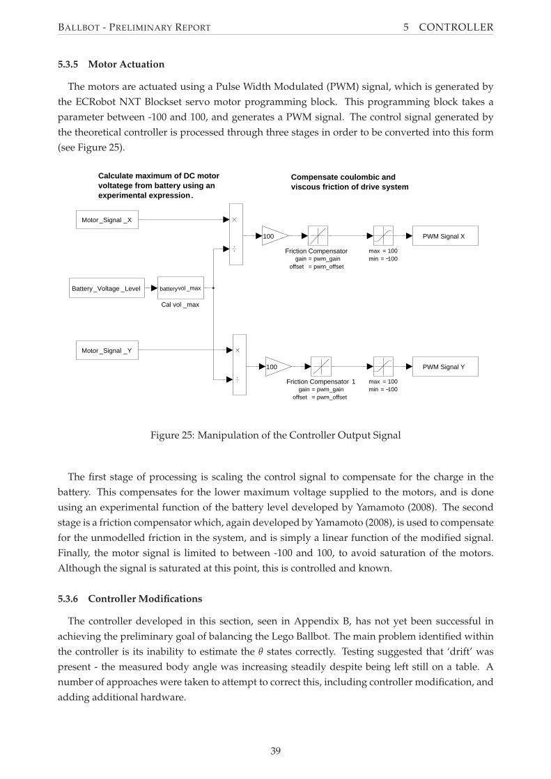
BALLBOT - PRELIMINARY REPORT 5 CONTROLLER
5.3.5 Motor Actuation
The motors are actuated using a Pulse Width Modulated (PWM) signal, which is generated by
the ECRobot NXT Blockset servo motor programming block. This programming block takes a
parameter between -100 and 100, and generates a PWM signal. The control signal generated by
the theoretical controller is processed through three stages in order to be converted into this form
(see Figure 25).
Calculate maximum of DC motorvoltatege from battery using anexperimental expression.
Compensate coulombic andviscous friction of drive system
max = 100min = −100
max = 100min = −100
100
100
Friction Compensator 1gain = pwm_gain
offset = pwm_offset
Friction Compensatorgain = pwm_gain
offset = pwm_offset
Cal vol _max
batteryvol _max
PWM Signal Y
PWM Signal X
Battery_Voltage _Level
Motor _Signal _Y
Motor _Signal _X
Figure 25: Manipulation of the Controller Output Signal
The first stage of processing is scaling the control signal to compensate for the charge in the
battery. This compensates for the lower maximum voltage supplied to the motors, and is done
using an experimental function of the battery level developed by Yamamoto (2008). The second
stage is a friction compensator which, again developed by Yamamoto (2008), is used to compensate
for the unmodelled friction in the system, and is simply a linear function of the modified signal.
Finally, the motor signal is limited to between -100 and 100, to avoid saturation of the motors.
Although the signal is saturated at this point, this is controlled and known.
5.3.6 Controller Modifications
The controller developed in this section, seen in Appendix B, has not yet been successful in
achieving the preliminary goal of balancing the Lego Ballbot. The main problem identified within
the controller is its inability to estimate the θ states correctly. Testing suggested that ‘drift’ was
present - the measured body angle was increasing steadily despite being left still on a table. A
number of approaches were taken to attempt to correct this, including controller modification, and
adding additional hardware.
39
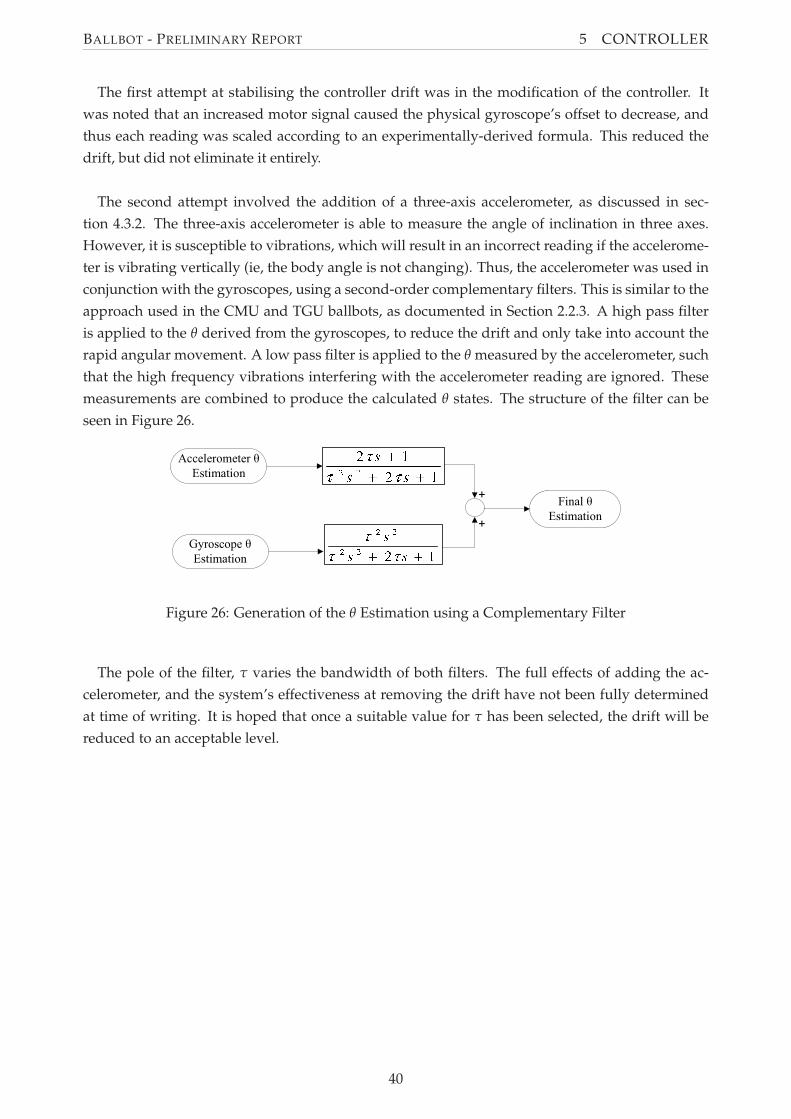
BALLBOT - PRELIMINARY REPORT 5 CONTROLLER
The first attempt at stabilising the controller drift was in the modification of the controller. It
was noted that an increased motor signal caused the physical gyroscope’s offset to decrease, and
thus each reading was scaled according to an experimentally-derived formula. This reduced the
drift, but did not eliminate it entirely.
The second attempt involved the addition of a three-axis accelerometer, as discussed in sec-
tion 4.3.2. The three-axis accelerometer is able to measure the angle of inclination in three axes.
However, it is susceptible to vibrations, which will result in an incorrect reading if the accelerome-
ter is vibrating vertically (ie, the body angle is not changing). Thus, the accelerometer was used in
conjunction with the gyroscopes, using a second-order complementary filters. This is similar to the
approach used in the CMU and TGU ballbots, as documented in Section 2.2.3. A high pass filter
is applied to the θ derived from the gyroscopes, to reduce the drift and only take into account the
rapid angular movement. A low pass filter is applied to the θ measured by the accelerometer, such
that the high frequency vibrations interfering with the accelerometer reading are ignored. These
measurements are combined to produce the calculated θ states. The structure of the filter can be
seen in Figure 26.
Figure 26: Generation of the θ Estimation using a Complementary Filter
The pole of the filter, τ varies the bandwidth of both filters. The full effects of adding the ac-
celerometer, and the system’s effectiveness at removing the drift have not been fully determined
at time of writing. It is hoped that once a suitable value for τ has been selected, the drift will be
reduced to an acceptable level.
40
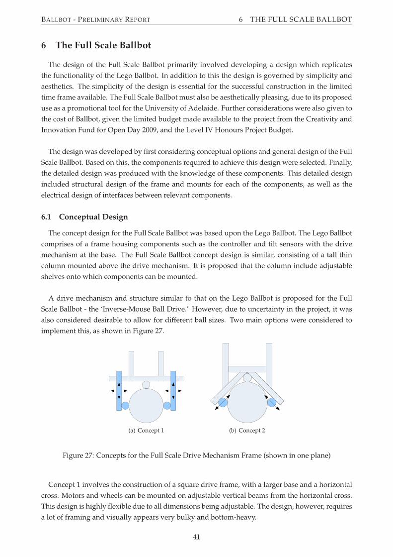
BALLBOT - PRELIMINARY REPORT 6 THE FULL SCALE BALLBOT
6 The Full Scale Ballbot
The design of the Full Scale Ballbot primarily involved developing a design which replicates
the functionality of the Lego Ballbot. In addition to this the design is governed by simplicity and
aesthetics. The simplicity of the design is essential for the successful construction in the limited
time frame available. The Full Scale Ballbot must also be aesthetically pleasing, due to its proposed
use as a promotional tool for the University of Adelaide. Further considerations were also given to
the cost of Ballbot, given the limited budget made available to the project from the Creativity and
Innovation Fund for Open Day 2009, and the Level IV Honours Project Budget.
The design was developed by first considering conceptual options and general design of the Full
Scale Ballbot. Based on this, the components required to achieve this design were selected. Finally,
the detailed design was produced with the knowledge of these components. This detailed design
included structural design of the frame and mounts for each of the components, as well as the
electrical design of interfaces between relevant components.
6.1 Conceptual Design
The concept design for the Full Scale Ballbot was based upon the Lego Ballbot. The Lego Ballbot
comprises of a frame housing components such as the controller and tilt sensors with the drive
mechanism at the base. The Full Scale Ballbot concept design is similar, consisting of a tall thin
column mounted above the drive mechanism. It is proposed that the column include adjustable
shelves onto which components can be mounted.
A drive mechanism and structure similar to that on the Lego Ballbot is proposed for the Full
Scale Ballbot - the ‘Inverse-Mouse Ball Drive.’ However, due to uncertainty in the project, it was
also considered desirable to allow for different ball sizes. Two main options were considered to
implement this, as shown in Figure 27.
(a) Concept 1 (b) Concept 2
Figure 27: Concepts for the Full Scale Drive Mechanism Frame (shown in one plane)
Concept 1 involves the construction of a square drive frame, with a larger base and a horizontal
cross. Motors and wheels can be mounted on adjustable vertical beams from the horizontal cross.
This design is highly flexible due to all dimensions being adjustable. The design, however, requires
a lot of framing and visually appears very bulky and bottom-heavy.
41
BALLBOT - PRELIMINARY REPORT 6 THE FULL SCALE BALLBOT
Concept 2 involves the drive mechanism supports being oriented at 45◦. The wheels are mounted
on this frame and as such can be adjusted along the axis of the frame, allowing for any ball size.
This concept requires less framework than concept 1, however is less adjustable as the drive wheels
can only be adjusted along one axis.
An additional advantage with both drive frame concepts is that they can be used to actuate the
ball at locations other than the side of the ball. This gives extra flexibility, and the facility to test
and utilise a drive mechanism which has not been constructed previously, such as that proposed
by Wu and Hwang (2008) as discussed in Section 2.2.1. Such a design would require the use
of omniwheels, however, does not require the simultaneous high and low friction coefficients as
required in the ‘Inverse-Mouse Ball Drive.’
The 45◦ drive mechanism frame was selected for the Full Scale Ballbot. This concept is simpler
to design and implement, and provides a more elegant design aesthetically.
6.2 Component Specification and Selection
The operational components required for the Full Scale Ballbot are the same as those required
for the Lego Ballbot - that is, a Controller, Tilt Sensors and Motors. Unlike the Lego Ballbot how-
ever, these components must be selected, as many options exist for each of these components. In
addition to this, other components such as the power supply, ball and wheels must also be selected.
6.2.1 Controller Hardware Selection
The requirements for the controller for the Full Scale ballbot are identical to those for the Lego
Ballbot. As such, the Lego NXT Mindstorms brick was selected to be used as the controller for
the Full Scale Ballbot, due to its suitability and the project team’s experience with the controller.
The NXT Mindstorms brick was deemed capable of controlling a ballbot system, as discussed in
Section 5.1, and thus suitable. The use of this controller also allows for easy modification of the
Lego Ballbot’s controller program for use in the Full Scale Ballbot.
6.2.2 Tilt Sensors
Due to the selection of the NXT Mindstorms Brick as the controller hardware, the simplest option
for the tilt sensors is to use the HiTechnic Gyroscopes and Accelerometer discussed in Section 4.1.
The use of these components ensures that minimal modifications will be required to the software
controller to estimate the tilt of the Ballbot. Furthermore, their performance has been tested on the
Lego Ballbot, and thus minimal further testing of these components is required.
The use of these Lego components, however, may introduce problems with mounting on the
frame, due to their lack of standard connections such as screw threads. However, this was consid-
ered insignificant due to the advantages gained using these components.
42
BALLBOT - PRELIMINARY REPORT 6 THE FULL SCALE BALLBOT
6.2.3 Motors
Selection of motors was based on two main criteria. The first was the desired performance
of the Full Scale Ballbot, and whether the motors could produce the required control authority
to achieve a stable ballbot. This was analysed via simulation, using motor characteristics from
available data sheets and approximate Ballbot physical characteristics. The second criteria was the
physical size and shape of the motors, and the ability to incorporate the motor in an aesthetically-
pleasing matter in the design. Other criteria included cost and availability. Motor selection was
limited to Brushed DC Servo motors, as these were considered preferable due to their similarity to
the Lego NXT Servo Motors, and their ease of control compared to brushless and other motors.
The motors selected for the Full Scale Ballbot are Leadshine DCM50205 DC brush servo motors.
These are 24V, 125W motors and provide a rated torque of 218.9 mNm at 3000rpm, and 1.59 Nm
at stall (see Appendix D). Simulation showed that these motors were capable of providing enough
torque for a stable ballbot, however it was apparent that more torque would result in better per-
formance. For this reason it was decided that all wheels would be driven, instead of having only
one driven wheel per plane, as in the Lego Ballbot. This effectively doubles the applied torque,
however, requires two additional motors. This option was considered preferable to using a gear-
box to increase torque, as the additional motor is cheaper than a gearbox and allows for a simpler
and less bulky mounting arrangement. The use of two motors in each plane also results in a more
balanced ballbot, both physically and aesthetically.
The selected motors are supplied with built in encoders. The encoders require a 5V supply and
produce a 500 count per turn quadrature encoder signal. The Lego NXT Servo motors produce an
equivalent signal, at 360 counts per turn, so it is believed that this encoder signal can be directly
used by the NXT brick with only minor alteration to the controller program and no additional
hardware.
6.2.4 Power Supply
A power supply is required on the Ballbot to power the motors and other electronics, including
the Lego NXT Mindstorms brick. The Full Scale Ballbot is a mobile robot, and thus it is desirable
that it use an on-board power source. Batteries are the simplest and cheapest sources of portable
energy, and thus are the power supplies to be used within this project. It was advised by supervisor
Associate Professor Ben Cazzolato that a Sealed Lead Acid (SLA) battery be used as the main
power source, so only this type of battery was considered for use. When selecting a battery, size,
weight, and capacity were the key selection criteria. It is required that the battery fit within the
centre column of the Ballbot, and that the weight not provide excessive load on the frame and
wheels. Thus the battery dimensions must not exceed approximately 200mm in any direction, and
total weight should not exceed 12kg. The battery must also be capable of providing the required
voltage and peak current for the motors.
The batteries selected for use in the Full Scale Ballbot are 12V SLA batteries available at Jaycar
Electronics. Two batteries will be used in series of provide the 24V required. These batteries pro-
vide high discharge capability and have deep discharge recovery characteristics. They also may
43
BALLBOT - PRELIMINARY REPORT 6 THE FULL SCALE BALLBOT
be used at any orientation, which is important due to possible oscillation in the ballbot body while
balancing or command tracking. A range of battery capacities is available, with larger capacity bat-
teries being larger and heavier. The particular battery selected is the 18Ah version, as this was the
largest capacity battery that meets the dimensional and weight requirements. The batteries have
dimensions 181x77x167 with a weight of 5.9kg, thus two adjacent batteries will have dimensions
181x154x167 with a total weight of 11.8kg, meeting the above specification.
6.2.5 Frame Material
The frame of the Full Scale Ballbot includes the drive mechanism and the column. As such it
is required that the frame material be light and strong enough to support the components in the
column. It was also desired that the frame material allow for ease of adjustability to provide the
features discussed in Section 6.1. Furthermore, the frame is perhaps the most important component
of the Ballbot in terms of aesthetics, and for this reason the material must be visually attractive.
Maytec Aluminium Extrusions were chosen to be used for the frame for a number of reasons.
Firstly, its neat appearance was deemed suitable for the Full Scale Ballbot Design. Secondly, it is a
product which is designed for frames, and thus can easily structurally accommodate the features
used on the Ballbot. Furthermore, its modular design and large variety of interacting components
allows for a robust and tailored design, which can be assembled with minimal use of the University
of Adelaide Mechanical Engineering Workshop. This was considered advantageous due to the
possibility of lengthy delays in the construction should the workshop be used.
6.2.6 Ball
The ball is used as the spherical driving wheel in the Full Scale Ballbot, and thus must fulfil
a number of criteria. First, the ball surface must have a high friction coefficient to eliminate slip
between the ball and the motor-driven actuating wheels, and the ball and the ground. Slip at these
interfaces will result in problems with control of the Full Scale Ballbot. Additionally, the ball must
be rigid, such that unnecessary damping is not introduced into the system. This will also reduce
the effectiveness of the controller, as the ball is modelled as being a rigid sphere in the derivation
of the dynamics (Section 3).
The Full Scale Ballbot has been designed to accommodate balls of varying sizes, due to the un-
certainty in the project. However, the nominal ball diameter for the design is 220mm. The ball used
for the Full Scale Ballbot is to be a bowling ball covered in rubber, in the form of ‘Plasti Dip.’ The
bowling ball provides a hard surface and thus the rigid property required. The thin layer of rub-
ber provides a high friction coefficient without significantly reducing this rigidity. This approach
was successfully used by Kumagai and Ochiai (2008) in the construction of the TGU Ballbot, which
required similar properties to that required by the Full Scale Ballbot design proposed in this report.
6.2.7 Wheels
Due to the nature of the proposed driving mechanism of the Full Scale Ballbot; standard, uni-
planar wheels would not be suitable for any arrangement other than the traditional, side-actuated,
44
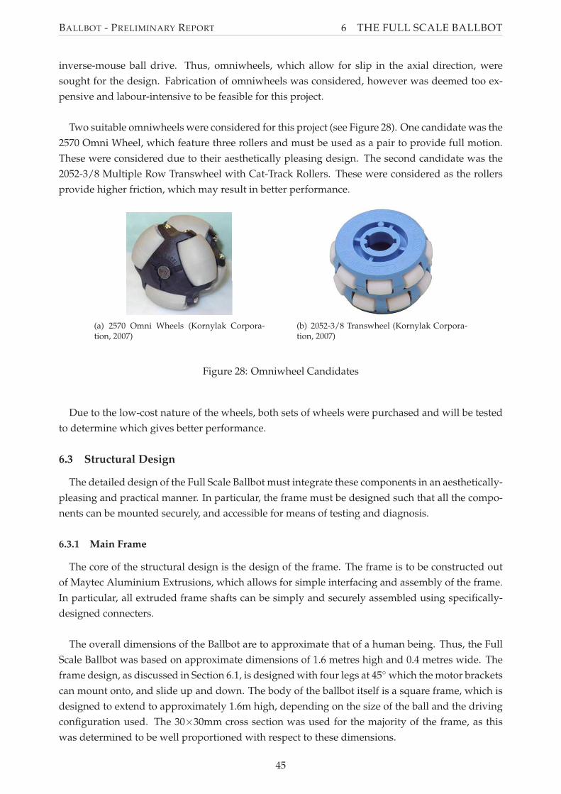
BALLBOT - PRELIMINARY REPORT 6 THE FULL SCALE BALLBOT
inverse-mouse ball drive. Thus, omniwheels, which allow for slip in the axial direction, were
sought for the design. Fabrication of omniwheels was considered, however was deemed too ex-
pensive and labour-intensive to be feasible for this project.
Two suitable omniwheels were considered for this project (see Figure 28). One candidate was the
2570 Omni Wheel, which feature three rollers and must be used as a pair to provide full motion.
These were considered due to their aesthetically pleasing design. The second candidate was the
2052-3/8 Multiple Row Transwheel with Cat-Track Rollers. These were considered as the rollers
provide higher friction, which may result in better performance.
(a) 2570 Omni Wheels (Kornylak Corpora-tion, 2007)
(b) 2052-3/8 Transwheel (Kornylak Corpora-tion, 2007)
Figure 28: Omniwheel Candidates
Due to the low-cost nature of the wheels, both sets of wheels were purchased and will be tested
to determine which gives better performance.
6.3 Structural Design
The detailed design of the Full Scale Ballbot must integrate these components in an aesthetically-
pleasing and practical manner. In particular, the frame must be designed such that all the compo-
nents can be mounted securely, and accessible for means of testing and diagnosis.
6.3.1 Main Frame
The core of the structural design is the design of the frame. The frame is to be constructed out
of Maytec Aluminium Extrusions, which allows for simple interfacing and assembly of the frame.
In particular, all extruded frame shafts can be simply and securely assembled using specifically-
designed connecters.
The overall dimensions of the Ballbot are to approximate that of a human being. Thus, the Full
Scale Ballbot was based on approximate dimensions of 1.6 metres high and 0.4 metres wide. The
frame design, as discussed in Section 6.1, is designed with four legs at 45◦ which the motor brackets
can mount onto, and slide up and down. The body of the ballbot itself is a square frame, which is
designed to extend to approximately 1.6m high, depending on the size of the ball and the driving
configuration used. The 30×30mm cross section was used for the majority of the frame, as this
was determined to be well proportioned with respect to these dimensions.
45
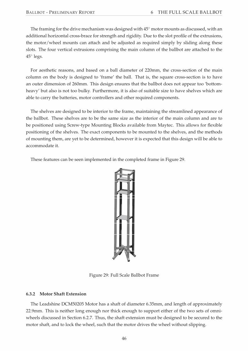
BALLBOT - PRELIMINARY REPORT 6 THE FULL SCALE BALLBOT
The framing for the drive mechanism was designed with 45◦ motor mounts as discussed, with an
additional horizontal cross-brace for strength and rigidity. Due to the slot profile of the extrusions,
the motor/wheel mounts can attach and be adjusted as required simply by sliding along these
slots. The four vertical extrusions comprising the main column of the ballbot are attached to the
45◦ legs.
For aesthetic reasons, and based on a ball diameter of 220mm, the cross-section of the main
column on the body is designed to ‘frame’ the ball. That is, the square cross-section is to have
an outer dimension of 260mm. This design ensures that the ballbot does not appear too ‘bottom-
heavy’ but also is not too bulky. Furthermore, it is also of suitable size to have shelves which are
able to carry the batteries, motor controllers and other required components.
The shelves are designed to be interior to the frame, maintaining the streamlined appearance of
the ballbot. These shelves are to be the same size as the interior of the main column and are to
be positioned using Screw-type Mounting Blocks available from Maytec. This allows for flexible
positioning of the shelves. The exact components to be mounted to the shelves, and the methods
of mounting them, are yet to be determined, however it is expected that this design will be able to
accommodate it.
These features can be seen implemented in the completed frame in Figure 29.
Figure 29: Full Scale Ballbot Frame
6.3.2 Motor Shaft Extension
The Leadshine DCM50205 Motor has a shaft of diameter 6.35mm, and length of approximately
22.9mm. This is neither long enough nor thick enough to support either of the two sets of omni-
wheels discussed in Section 6.2.7. Thus, the shaft extension must be designed to be secured to the
motor shaft, and to lock the wheel, such that the motor drives the wheel without slipping.
46
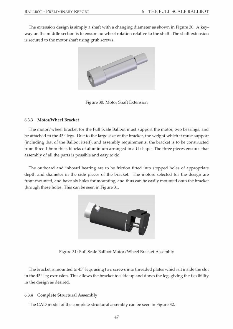
BALLBOT - PRELIMINARY REPORT 6 THE FULL SCALE BALLBOT
The extension design is simply a shaft with a changing diameter as shown in Figure 30. A key-
way on the middle section is to ensure no wheel rotation relative to the shaft. The shaft extension
is secured to the motor shaft using grub screws.
Figure 30: Motor Shaft Extension
6.3.3 Motor/Wheel Bracket
The motor/wheel bracket for the Full Scale Ballbot must support the motor, two bearings, and
be attached to the 45◦ legs. Due to the large size of the bracket, the weight which it must support
(including that of the Ballbot itself), and assembly requirements, the bracket is to be constructed
from three 10mm thick blocks of aluminium arranged in a U-shape. The three pieces ensures that
assembly of all the parts is possible and easy to do.
The outboard and inboard bearing are to be friction fitted into stopped holes of appropriate
depth and diameter in the side pieces of the bracket. The motors selected for the design are
front-mounted, and have six holes for mounting, and thus can be easily mounted onto the bracket
through these holes. This can be seen in Figure 31.
Figure 31: Full Scale Ballbot Motor/Wheel Bracket Assembly
The bracket is mounted to 45◦ legs using two screws into threaded plates which sit inside the slot
in the 45◦ leg extrusion. This allows the bracket to slide up and down the leg, giving the flexibility
in the design as desired.
6.3.4 Complete Structural Assembly
The CAD model of the complete structural assembly can be seen in Figure 32.
47
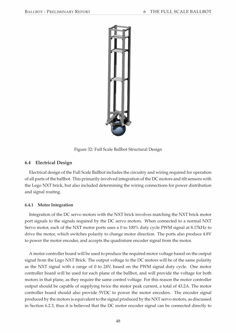
BALLBOT - PRELIMINARY REPORT 6 THE FULL SCALE BALLBOT
Figure 32: Full Scale Ballbot Structural Design
6.4 Electrical Design
Electrical design of the Full Scale Ballbot includes the circuitry and wiring required for operation
of all parts of the ballbot. This primarily involved integration of the DC motors and tilt sensors with
the Lego NXT brick, but also included determining the wiring connections for power distribution
and signal routing.
6.4.1 Motor Integration
Integration of the DC servo motors with the NXT brick involves matching the NXT brick motor
port signals to the signals required by the DC servo motors. When connected to a normal NXT
Servo motor, each of the NXT motor ports uses a 0 to 100% duty cycle PWM signal at 8.17kHz to
drive the motor, which switches polarity to change motor direction. The ports also produce 4.8V
to power the motor encoder, and accepts the quadrature encoder signal from the motor.
A motor controller board will be used to produce the required motor voltage based on the output
signal from the Lego NXT Brick. The output voltage to the DC motors will be of the same polarity
as the NXT signal with a range of 0 to 24V, based on the PWM signal duty cycle. One motor
controller board will be used for each plane of the ballbot, and will provide the voltage for both
motors in that plane, as they require the same control voltage. For this reason the motor controller
output should be capable of supplying twice the motor peak current, a total of 43.2A. The motor
controller board should also provide 5VDC to power the motor encoders. The encoder signal
produced by the motors is equivalent to the signal produced by the NXT servo motors, as discussed
in Section 6.2.3, thus it is believed that the DC motor encoder signal can be connected directly to
48
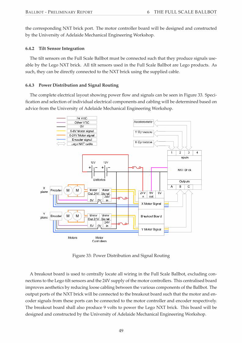
BALLBOT - PRELIMINARY REPORT 6 THE FULL SCALE BALLBOT
the corresponding NXT brick port. The motor controller board will be designed and constructed
by the University of Adelaide Mechanical Engineering Workshop.
6.4.2 Tilt Sensor Integration
The tilt sensors on the Full Scale Ballbot must be connected such that they produce signals use-
able by the Lego NXT brick. All tilt sensors used in the Full Scale Ballbot are Lego products. As
such, they can be directly connected to the NXT brick using the supplied cable.
6.4.3 Power Distribution and Signal Routing
The complete electrical layout showing power flow and signals can be seen in Figure 33. Speci-
fication and selection of individual electrical components and cabling will be determined based on
advice from the University of Adelaide Mechanical Engineering Workshop.
Figure 33: Power Distribution and Signal Routing
A breakout board is used to centrally locate all wiring in the Full Scale Ballbot, excluding con-
nections to the Lego tilt sensors and the 24V supply of the motor controllers. This centralised board
improves aesthetics by reducing loose cabling between the various components of the Ballbot. The
output ports of the NXT brick will be connected to the breakout board such that the motor and en-
coder signals from these ports can be connected to the motor controller and encoder respectively.
The breakout board shall also produce 9 volts to power the Lego NXT brick. This board will be
designed and constructed by the University of Adelaide Mechanical Engineering Workshop.
49
BALLBOT - PRELIMINARY REPORT 7 FUTURE WORK
7 Future Work
Further work is still required for the success of both the Lego and Full Scale Ballbots. It is aimed
to have both the Ballbots complete and balancing so they can be displayed at the University of
Adelaide’s Open Day, 16th August 2009. Details of the work schedule to achieve this objective is
shown in the Gantt Chart (Appendix C).
7.1 Lego Ballbot
Construction of the Lego Ballbot is complete, however the controller is not yet successful at
balancing the Lego ballbot. As such the most important work to be performed on the Lego Ballbot
is further testing and refinement of the controller to produce a stable balancing ballbot. Once the
Lego Ballbot is balancing command tracking will be added to allow the ballbot to move given a
command signal. Bluetooth communication will be implemented to provide the command signal.
7.1.1 Controller Testing and Refinement
The controller on the Lego Ballbot does not currently balance the Lego ballbot. Possible reasons
for this include inaccuracy in the state measurements due to noise drift in the gyros, slip between
the driving wheels and the ball or the ball and the ground, or an error in the controller program.
Further testing will be undertaken to determine the reason for a non-successful controller such that
a solution can be found so a balancing Ballbot can be achieved. This may also involve redesign of
the controller or Lego Ballbot.
7.1.2 Command Tracking
Currently, the controller program attempts to stabilise the Ballbot about its zero position, that is,
balance upright at its initial position. Command tracking will be added to the controller program to
allow the Ballbot to move in any direction at a given velocity and/or point to point. Both methods
will be tested and one or both may be implemented depending on each method’s performance.
7.1.3 Bluetooth Control
The NXT brick supports Bluetooth communication, and this is intended to be used to wirelessly
give the Lego ballbot its command signal. This will allow a person to control the Lego ballbot
using some form of Bluetooth compatible game controller. Implementation of Bluetooth control
will require developing a method of interfacing either from the game controller to PC and then to
the Lego Ballbot or directly from the game controller to the ballbot, such that the command signal
from the game controller can be sent to the Lego Ballbot.
7.2 Full Scale Ballbot
The design of the Full Scale Ballbot is yet to be finalised. Upon the completion of the design,
the construction of the ballbot will be undertaken. Following this, the software controller will be
modified for use on the Full Scale Ballbot.
50
BALLBOT - PRELIMINARY REPORT 7 FUTURE WORK
7.2.1 Detail Design
The majority of the detailed design of the Full Scale Ballbot has been completed. However, some
components are still to be finalised, in particular the motor/wheel bracket, shaft extension and
electrical component selection and design.
It is expected that these designs be finalised within a week of submission of this report.
7.2.2 Construction
The purchasing process for the long lead-time items required for the construction of the Ballbot
has begun, such that the components will be available when construction begins.
The motor/wheel brackets, shaft extension, motor controller and breakout board are to be manu-
factured by the University of Adelaide Mechanical Engineering Workshop, once the designs have
been finalised. It is proposed that the frame be built by Metri-Tek Tooling, a local supplier of
Maytec Aluminium Extrusions. This will reduce the dependence on the workshop, which is a
source of potential delays.
It is expected that the Full Scale Ballbot will be constructed on schedule due to this distribution
of work load, and the simple design of the Full Scale Ballbot.
7.2.3 Controller
The controller for the Full Scale Ballbot is intended to be a modified version of the controller
used for the Lego Ballbot. Modifications to the controller to make it suitable for the Full Scale
ballbot primarily includes recalculating and testing controller gains. Other possible modifications
include variations to the sensor readings and motor output signals as appropriate to the selected
hardware.
51
BALLBOT - PRELIMINARY REPORT REFERENCES
References
Alain J. Brizard. An Introduction To Lagrangian Mechanics. World Scientific Publishing Company,
2008.
Hitachi. Hitachi Single-Chip Microcomputer H8/3052 Z-TAT Hardware Manual, 2001.
HiTechnic Products. HiTechnic Products, 2008. Viewed 30th April 2009,
http://www.hitechnic.com.
Philippe E. Hurbain. Philo’s Home Page, 2009. Viewed 6th May 2009,
http://www.philohome.com.
Kornylak Corporation. OMNI Wheels, 2007. Viewed 19th May 2009,
http://www.omniwheel.com.
Masaaki Kumagai and Takaya Ochiai. Development of a robot balancing on a ball. In International
Conference on Control, Automation and Systems, Seoul, Korea, October 2008.
TB Lauwers, GA Kantor, and RL Hollis. A dynamically stable single-wheeled mobile robot with
inverse mouse-ball drive. In Proceedings IEEE International Conference on Robotics and Automation,
Orlando, Florida, May 2006. IEEE.
Tom Lauwers, George Kantor, and Ralph Hollis. One is enough! In 12th International Symp. on
Robotics Research, pages 1–10, San Francisco, October 2005.
Ching-Wen Liao, Ching-Chih Tsai, Yi Yu Li, and Cheng-Kai Chan. Dynamic modeling and sliding-
mode control of a ball robot with inverse mouse-ball drive. In SICE Annual Conference, The
University Electro-Communicaions, Japan, August 2008.
Anish K Mampetta. Automatic transition of ballbot from statically stable state to dynamically sta-
ble state. Master’s thesis, Carnegie Mellon University, Pittsburgh, Pennsylvania 15213, August
2006.
Eric M Schearer. Modeling dynamics and exploring control of a single-wheeled dynamically stable
mobile robot with arms. Master’s thesis, Carnegie Mellon University, Pittsburgh, Pennsylvania
15213, August 2006.
Segway Inc. Segway, 2009. Viewed 28th April 2009, http://www.segway.com.
The LEGO Group. Lego Mindstorms NXT Hardware Developer Kit. The LEGO Group, 1 edition, 2006.
CW Wu and CK Hwang. A novel spherical wheel driven by omniwheels. In Proceedings of the
Seventh International Conference on Machine Learning and Cybernetics, pages 3800–3803, Kunming,
July 2008.
Yorihisa Yamamoto. Nxtway-gs model-based design - control of self-balancing two-wheeled robot
built with lego mindstorms nxt, February 2008.
Yorihisa Yamamoto. Nxt ballbot model-based design - control of a self-balancing robot on a ball,
built with lego mindstorms nxt., April 2009.
52
BALLBOT - PRELIMINARY REPORT A MATLAB CODE
APPENDIX
A Matlab Code
This appendix includes the code used to generate the equations of motion for a simplified ballbot
system. Additionally, the code also prints out and displays the equations in a form suitable for
inclusion into this report.
53
BALLBOT - PRELIMINARY REPORT B SIMULINK CONTROLLER
B Simulink Controller
Presented in this appendix is the original ballbot controller for the Lego Ballbot, before modifi-
cations were made in attempt to compensate for the drift in the calculated body angle state.
66
BALLBOT - PRELIMINARY REPORT C GANTT CHART
C Gantt Chart
This appendix includes the Gantt chart for the Ballbot project.
90
BALLBOT - PRELIMINARY REPORT D COMPONENT DATASHEETS
D Component Datasheets
This appendix includes the datasheets of components to be used in the Full Scale Ballbot.
92
BALLBOT - PRELIMINARY REPORT E NXT MINDSTORMS PARTS LIST
E NXT Mindstorms Parts List
This appendix lists the parts in the 8527 Lego NXT Mindstorms kit. It was obtained from
http://www.bricklink.com.
100
Recommended