© 2017/12/15, Lunatone Industrielle Elektronik GmbH DALI Cockpit
DALI Cockpit
Startup Guide V5
DALI Configuration Tool
Commissioning of DALI-
components and DALI-line
Traffic Monitoring

2
© 2017/12/15 Lunatone Industrielle Elektronik GmbH DALI Cockpit, Startup Guide V5
DALI Cockpit Configuration Tool
Content
Content .................................................................................................................................................... 2
1. Software Installation ....................................................................................................................... 2
1.1. Requirements .......................................................................................................................... 2
1.2. Installation ............................................................................................................................... 3
2. Registration ..................................................................................................................................... 5
3. System Preparation ......................................................................................................................... 6
3.1. Build connection to the DALI-System ...................................................................................... 6
3.2. Language Settings .................................................................................................................... 7
4. Test Communication ....................................................................................................................... 8
5. DALI System Commissioning ........................................................................................................... 8
5.1. DALI Addressing Procedure ..................................................................................................... 8
5.2. DALI Device Localisation ........................................................................................................ 12
5.2.1. Localize Checkbox .......................................................................................................... 12
5.2.2. Physical Selection List .................................................................................................... 13
5.3. Scene Configuration (Broadcast) ........................................................................................... 13
5.4. Group Handling ..................................................................................................................... 14
5.5. Configuration of Components ............................................................................................... 15
5.6. Macro Usage – Individualize your Application ...................................................................... 19
6. DALI-Line Monitoring .................................................................................................................... 21
7. Firmware Update of Lunatone devices ......................................................................................... 22
8. Offline Mode ................................................................................................................................. 24
8.1. Save and open network files ................................................................................................. 24
8.2. Edit network files and apply changes to DALI lines ............................................................... 25
1. Software Installation
1.1. Requirements
For the connection from your PC to a DALI-line an interface is required. Lunatone has
different interfaces available that are supported by the DALI Cockpit software. These are the
DALI USB, the DALI RS232 SCI2 and the DALI 4Net. Please check out the products on our

3
© 2017/12/15 Lunatone Industrielle Elektronik GmbH DALI Cockpit, Startup Guide V5
website if you do not already have one in use. The DALI Cockpit software has been tested
under Windows XP, Windows 7 and Windows 10.
1.2. Installation
The DALI Cockpit software package consists of three parts, namely the DALI-Cockpit, the DALI
Monitor and the DALI BusServer. We recommend the installation of all components to utilize
full functionality. The BusServer is required for the communication between PC and the
interface (DALI USB, DALI RS232 SCI2 or DALI 4Net). The DALI Cockpit itself is the
configuration tool, while the DALI Monitor is a sniffing tool for DALI-line traffic monitoring.
Unpack the ZIP-File first and then execute the DALI_Cockpit_Vxxx.exe to start the installation
process. After choosing the components and the destination folder the installation process
can be started by pressing the “Install”-Button.
4
© 2017/12/15 Lunatone Industrielle Elektronik GmbH DALI Cockpit, Startup Guide V5
When the installation is completed the final window has to be closed manually.
After installation is finished you will find a DALI-Cockpit folder in the start menu entries.

5
© 2017/12/15 Lunatone Industrielle Elektronik GmbH DALI Cockpit, Startup Guide V5
2. Registration
When the DALI Cockpit is opened for the first time after installation a window pops up where
you can register and request a key for free or continue without registration and use the 30
day trial version.
Hit the request key button to get to the registration form.
All three fields have to be filled to succesfull request a key. You will get your registration key
via email, if it doesn’t appear in your inbox be sure to also check the spam folder.

6
© 2017/12/15 Lunatone Industrielle Elektronik GmbH DALI Cockpit, Startup Guide V5
After using a correct key and pressing the activate button you will get a new window where
you have to fill in your registration data again. By confirming this window the message box
from above will appear and DALI Cockpit is registered.
3. System Preparation
3.1. Build connection to the DALI-System
Connect the PC to the DALI-line via DALI USB, DALI SCI RS232 or DALI 4Net interface. After
having started the DALI Cockpit DALI USB interfaces are found and shown automatically in
the component tree. To connect to one of the other Interfaces choose “DALI Bus → Bus
Interface” in the menu. For a connection with a DALI SCI RS232 you have to select COM and
the respective port. For a DALI 4Net you have to select Ethernet and Lunatone TCP and then
fill in the IP address. You also can search after DALI 4Net devices in the network with the
“Search” button.
7
© 2017/12/15 Lunatone Industrielle Elektronik GmbH DALI Cockpit, Startup Guide V5
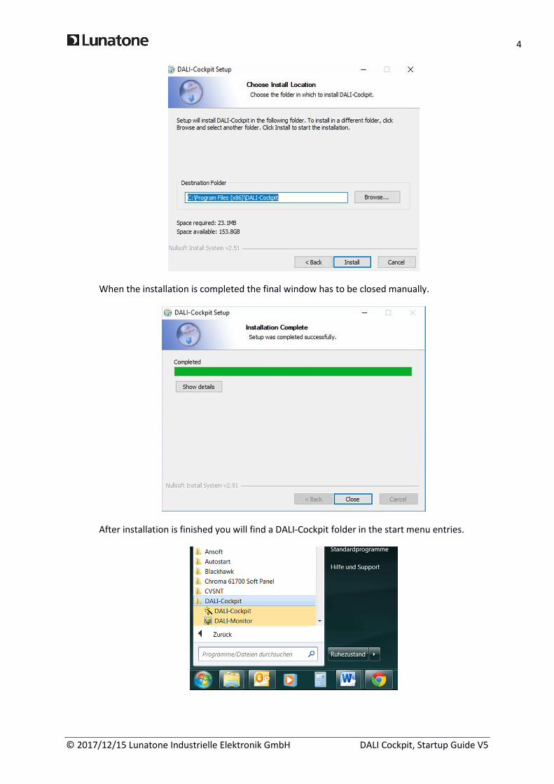
If there is no interface found, check out the connection between your PC and the DALI
interface. If you use a DALI USB or DALI 4Net the interface should be detected even in the
case of no DALI-line connected. In case you use a DALI SCI2 you have to connect the DALI-line
before the DALI Cockpit can recognise the interface.
For Further details on the interfaces check the datasheets of the interfaces on the Lunatone
website.
HINT:
If your DALI Interface won’t connect to your PC you can try to close the DALIBusServer (an
application that is running in the background during the time DALI Cockpit or Monitor is
open). Thereto close DALI Cockpit and Monitor and right click the DALIBusServer symbol in
the info area of windows and exit the application.
3.2. Language Settings
The language can be changed in the preferences menu. The languages available are German
and English. DALI Cockpit has to be restarted to activate this change.

8
© 2017/12/15 Lunatone Industrielle Elektronik GmbH DALI Cockpit, Startup Guide V5
4. Test Communication
Before starting commissioning the DALI communication should be tested. In the menu of the
DALI USB the DALI communication can be tested easily by sending commands broadcast on
the DALI-line. This can be done e.g. by pressing RECALL MAX and OFF button and check the
reaction of DALI control gear (optical feedback). Furthermore you can check the traffic on the
DALI-line with the help of the DALI monitor (check chapter 6 for details).
5. DALI System Commissioning
5.1. DALI Addressing Procedure
The addressing procedure can be initiated by pressing the “Addressing“- button on the DALI
USB site. An alternative is to start the process via the DALI-Bus menu.
In the DALI Addressing Wizard there are several options. You can choose between system
extension and new installation. Furthermore the physical selection mode for luminaries and
an optical feedback for detected devices can be selected.
Commissioning
Addressing
Scene Configuration
Sends DALI
command RECALL
MAX to all devices
Sends DALI
command OFF to all
devices

9
© 2017/12/15 Lunatone Industrielle Elektronik GmbH DALI Cockpit, Startup Guide V5
You can select between a complete new installation and system extension. Performing a
complete new installation will delete all existing DALI-addresses and already defined group
dependencies, whereas the system extension mode keeps already defined DALI addresses
and group dependencies, only unaddressed devices will get an address.
In the system extension mode you can furthermore select which kind of devices the DALI
Cockpit should search for: Control Gear, Control Devices using Random Addressing Method
and/or Input Devices using Addressing Method with physical selection.
or

10
© 2017/12/15 Lunatone Industrielle Elektronik GmbH DALI Cockpit, Startup Guide V5
After the automatic process has finished you will get the following window with a popup
request to manually add control devices by pressing buttons on the device (Like DALI-Switch,
DALI MC or DALI Touch Panel).
In this example we will add a DALI switch and a wDALI Remote. When detected correctly the
components will be added in the DALI device list as shown below.

11
© 2017/12/15 Lunatone Industrielle Elektronik GmbH DALI Cockpit, Startup Guide V5
Pressing the finish button will close the popup, “Next”-Button finishes the Addressing
procedure. For leaving the DALI Addressing Wizard finally press “Done”.
After leaving the DALI Addressing Wizard you will find an overview of all addressed DALI-
components in your system in the component tree on the left.
All Lunatone devices will be shown with a specific symbol, name and DALI address. All other
devices will show up accordingly to their DALI device type and with DALI address.

12
© 2017/12/15 Lunatone Industrielle Elektronik GmbH DALI Cockpit, Startup Guide V5
Sometimes it can happen that a DALI Conflict is shown in DALI Cockpit, if you add additional
devices to an existing DALI system. To resolve this, delete this DALI address and do a new
addressing procedure (extension).
Conflicts can be avoided by always deleting the address of devices you previously addressed
before adding them to the DALI system.
HINT:
For a better overview the devices can be renamed by right click → rename. The DALI
address is not changed.
5.2. DALI Device Localisation
5.2.1. Localize Checkbox
For easier localisation of your lamps and some control devices you can select the specific
device or group and use the localize checkbox to switch between two states.
• Control gear (e.g LED Dimmer DT6/8, PD):
Switches between Max and Min Level. Checking sends RECALL MAX and unchecking
sends RECALL MIN.

13
© 2017/12/15 Lunatone Industrielle Elektronik GmbH DALI Cockpit, Startup Guide V5
• DALI CS / Touchpanel (BT):
Switches between LED blinks and LED blinks not. Checking enables blinking and
unchecking disables it.
5.2.2. Physical Selection List
The “Physical Selection List” can be used for the devices DALI MC, DALI MC+, DALI Switch and
DALI Touchpanel and contains the order in which the inputs/buttons are triggered. This
should make locating of control devices after addressing easier. To create a “Physical
Selection List” you have to trigger inputs/button at the end of the addressing routine when
the “User action required” window appears. The device inputs will show up according the
order you physically trigger them. This list can also be exported as a *.csv table.
5.3. Scene Configuration (Broadcast)
For fast scene configuration (or broadcast and group configuration) the “Configure Scene”
menu is helpful.
14
© 2017/12/15 Lunatone Industrielle Elektronik GmbH DALI Cockpit, Startup Guide V5
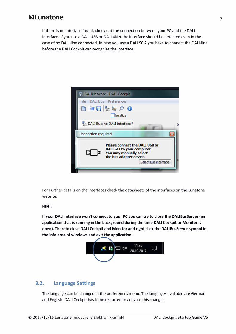
In the menu you can enter the effective range you want to configure, the type of scene (level
only or special DT8 color scene type), the scene number and the values. Pressing “Save
Scene” will store the parameters to the devices affected by the selected address range.
Another possibility to configure scenes for a device is on the device page itself. However this
menu is helpful to configure several devices at once.
5.4. Group Handling
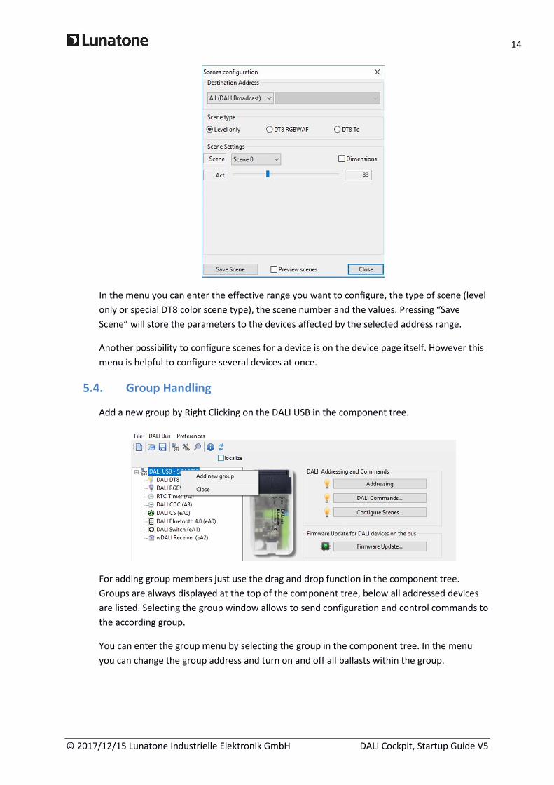
Add a new group by Right Clicking on the DALI USB in the component tree.
For adding group members just use the drag and drop function in the component tree.
Groups are always displayed at the top of the component tree, below all addressed devices
are listed. Selecting the group window allows to send configuration and control commands to
the according group.
You can enter the group menu by selecting the group in the component tree. In the menu
you can change the group address and turn on and off all ballasts within the group.

15
© 2017/12/15 Lunatone Industrielle Elektronik GmbH DALI Cockpit, Startup Guide V5
5.5. Configuration of Components
By choosing a DALI-component on the left you enter the configuration site of this
component.
Find examples of a LED Dimmer and a RGB-Dimmer below.
In general the control gear site is separated in the device info block, and the configuration
block. In the configuration block group dependencies and scene values can be defined as well
as all standard DALI parameters and other helpful Lunatone specific parameters.
For other device types (especially DT4, DT5 and DT7) additional settings may be available.
They can be entered by additional tabs of the configuration block.
Groups
Devices

16
© 2017/12/15 Lunatone Industrielle Elektronik GmbH DALI Cockpit, Startup Guide V5
DALI controls configuration sites are divided in a device info block and a device setting block.
The device setting block often consists of several tabs, in most cases a general settings tab
and a tab for each input or sensor (depending on device).
17
© 2017/12/15 Lunatone Industrielle Elektronik GmbH DALI Cockpit, Startup Guide V5
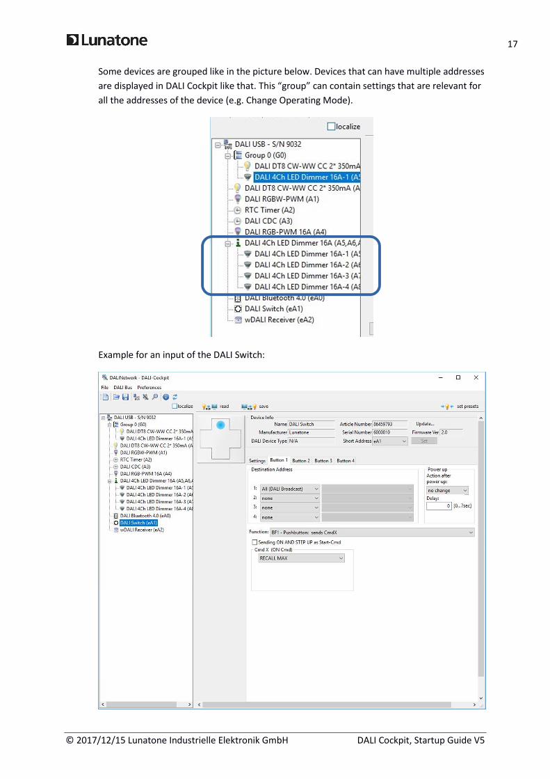
Some devices are grouped like in the picture below. Devices that can have multiple addresses
are displayed in DALI Cockpit like that. This “group” can contain settings that are relevant for
all the addresses of the device (e.g. Change Operating Mode).
Example for an input of the DALI Switch:

18
© 2017/12/15 Lunatone Industrielle Elektronik GmbH DALI Cockpit, Startup Guide V5
For most controls you can generally define:
• Target address: What DALI devices should be controlled
• Button Function: Behaviour types if button is pressed (e.g. long/short press)
• Command(s): Action to send for the target address
For more detailed information to the parameters that can be configured check the
datasheets of the components on the Lunatone site.
When a device is right clicked a menu with multiple entries shows up.
Options available for all devices:
• Rename: Changes the name of a device. The name is not saved in the device, just in
the network file.
• Hide: Will hide a specific device. Can be displayed again by addressing with system
extension.
Delete address: Deletes the address of a device, but it is still listening to broadcast
commands.
• Reset: Sets the reset values.
• Reset and delete address: Is a combination of the two points above.
Additional options (only supported by some of our devices):
• Export device settings: Exports the data into a *.xds file.
• Import device settings: Imports data from a *.xds file.

19
© 2017/12/15 Lunatone Industrielle Elektronik GmbH DALI Cockpit, Startup Guide V5
HINT:
With the “Read”-Button at the top of the form the actual component properties are read
from the device. After having made changes press the “Save”-Button to store the
properties to the DALI-device.
5.6. Macro Usage – Individualize your Application
Each button of a control device can be configured by defining button function (e.g. different
action for short/long press, toggle button, stairways control etc.), the effective range and the
DALI-Cmd that should be sent in case of the defined input action. In the screenshot above the
button 1 is configured to send RECALL MAX broadcast on a button press.
Most devices also provide the possibility to use predefined macros or user-defined command
lists instead of sending a DALI Cmd to the bus.
A user-defined cmd-list is an individual list of DALI-cmds. In this case the destination-
addresses defined on the top of the page have no effect because the addresses are already
defined in the DALI cmds themselves.
A user defined cmd-list can be generated using the “DALI-command” menu (DALI Bus -> DALI
Commands -> Commands Over Time).

20
© 2017/12/15 Lunatone Industrielle Elektronik GmbH DALI Cockpit, Startup Guide V5
With the help of this editor a cmd-list can be generated by adding several commands of your
choice:
For each command in the list a destination address and the DALI command can be
configured. Furthermore the delay time after the command can be defined. E.g. adding 3
Direct Act Power Cmds for different destinations to the command list will result in a list like
the following:

21
© 2017/12/15 Lunatone Industrielle Elektronik GmbH DALI Cockpit, Startup Guide V5
After saving this list to a file (*.cot) it can be loaded for each user-defined command list of
your controls.
The user defined command-lists are a powerful feature. They offer a wide spectrum of
additional functions that are not supported by the embedded functions of the device itself.
As an example it is possible to send commands to different destinations on short and long
button press (whereas in the standard setup there is always the same destination valid for
the function defined for the button) or to send several commands to different destinations
on a button press. Furthermore a command-list can be used to reconfigure devices (using
configuration commands), which can be used to change the function of a control device or to
realize dynamic groups and scenes.
HINT:
Please note that user defined commands lists offer high flexibility. Due to this reason each
entry in the command list contains information about the destination address. Hence each
user defined macro is unique and the list has to be adapted if its function should be applied
to another address range!
6. DALI-Line Monitoring
With the DALI monitor the traffic on the DALI-line can be visualised. This may be helpful to
analyse if your controls are configured correctly and send the correct commands to control
gear on specific events.

22
© 2017/12/15 Lunatone Industrielle Elektronik GmbH DALI Cockpit, Startup Guide V5
An example is shown below.
The monitor log can be saved to a file. This can be an important help for various analysis.
7. Firmware Update of Lunatone devices
For using the firmware update functions for Lunatone DALI-components you need an
activation key to activate this feature (supported from DALI-Cockpit version 1.0.6 and
higher). For using this feature select the DALI-USB device in the component tree.
Then press the “Firmware Update” button and enter the activation key to enable this tool.
Select the device and the location of the software and press Start.
HINT:
All devices that match the type you selected are updated. If you don’t want to update all of
them you have to disconnect them from the DALI-line during the update procedure.

23
© 2017/12/15 Lunatone Industrielle Elektronik GmbH DALI Cockpit, Startup Guide V5
Another option to enter the Update menu is to press the “Update …” button on the right top
of the device info block.
The duration of the update procedure can last up to 15 minutes.
When the update has finished you get the message “Data loaded OK”.

24
© 2017/12/15 Lunatone Industrielle Elektronik GmbH DALI Cockpit, Startup Guide V5
8. Offline Mode
8.1. Save and open network files
With “File → Save As“ a *.dnc File is created and stores the current configuration you have in
your Cockpit. This file includes all parameters from all your devices.
Note: The Parameters from the devices must be read out once.
After the file is saved, it can be opened without connection to the DALI line. To look into the
configuration of the devices, Offline Mode has to be activated (DALI Bus → Work Offline).

25
© 2017/12/15 Lunatone Industrielle Elektronik GmbH DALI Cockpit, Startup Guide V5
When OFFLINE appears above the component tree the devices can be accessed without
loading data from the bus.
HINT:
With this file it is possible to change all parameters without directly changing the device
settings. When connecting to the DALI USB / Application, the default configuration is that
parameters are read out from the devices and overwrite the settings from the file. If you
want to apply the changes to the actual DALI lines follow the instructions in 25.
8.2. Edit network files and apply changes to DALI lines
First you have to load a *.dnc File (Creation of a *.dnc File is described in 24) via “File →
Open”. After the devices are shown in the component tree you have to activate the offline
mode (DALI Bus → Work Offline).
Then you click on the devices you want to configure, change the settings to your needs and
click “save” (above the device configuration) and afterwards on “File → Save“.
Now if you are again connected to the DALI-line you go into Settings → OpQons and disable
the “Read devices on selection“ checkbox and click OK.

26
© 2017/12/15 Lunatone Industrielle Elektronik GmbH DALI Cockpit, Startup Guide V5
Load the *.dnc File using “File → Open“. ARerwards click on the device you changed seSngs
and press on save. The configuration is now stored into the device.
Recommended