1
Data Management: Databases and OrganizationsRichard Watson
Summary of Chapter 7 and Basic Structures prepared by Kirk Scott
2
Data Modeling and SQL
• Chapter 7. Data Modeling• Reference: Basic Structures
3
Chapter 7. Data Modeling
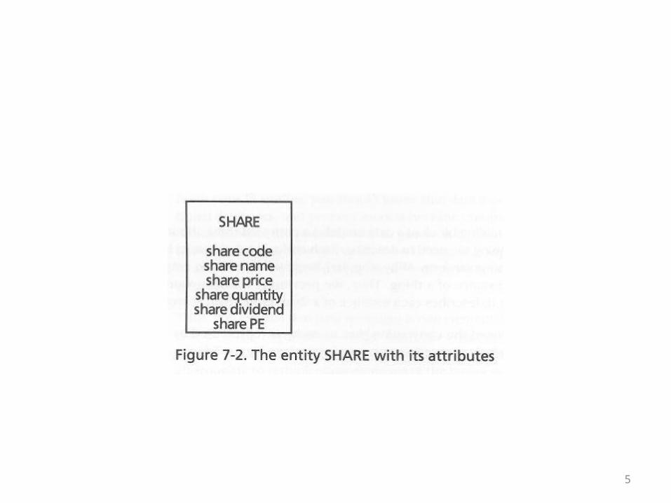
• The building blocks of data modeling should be familiar to you:
• Entities• Attributes• Relationships• Identifiers (keys)• The next five overheads taken from chapter 7
review the ER notation for these things
4
5
6
7
8
9
• A model is the starting point for creating a database• No table need be created before the model is
complete• Quality of the data model is essential• The model should be well formed: It should follow
the basic rules for entities, attributes, relationships, and keys
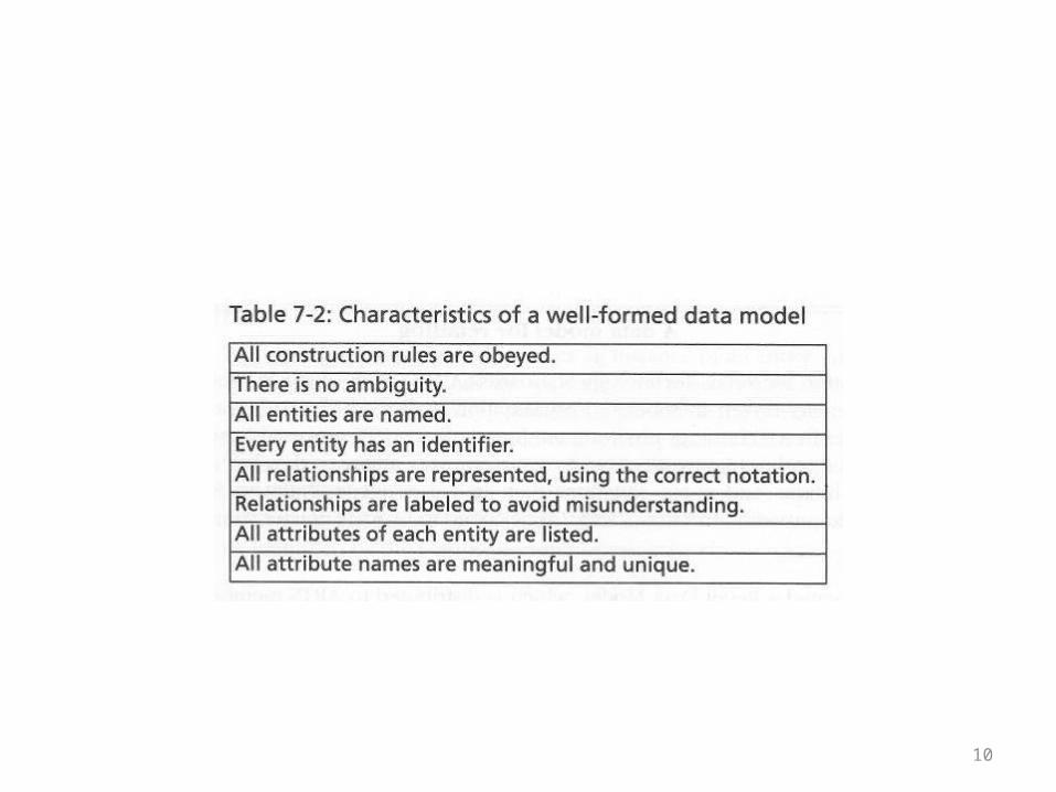
• The following overhead summarizes the characteristics of a well formed model
10
11
• A quality data model should be high-fidelity• This means that it has to accurately and
completely model the situation in the problem domain
• A model which is well formed but does not model the problem domain is useless from a practical point of view
12
• The phrase “quality improvement” in the context of data models means this:
• It is unrealistic to assume that a good data model can be created on the first try
• A data model will evolve as technical mistakes are caught
• More importantly, it will evolve as a result of interaction with users as the problem domain and requirements are more completely understood
13
The Stock Example
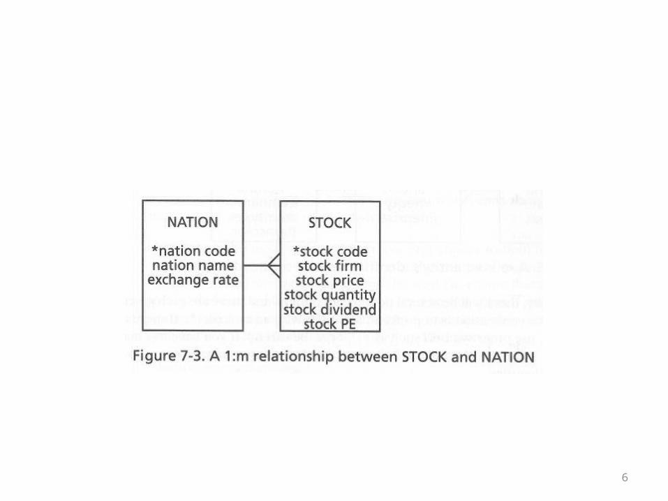
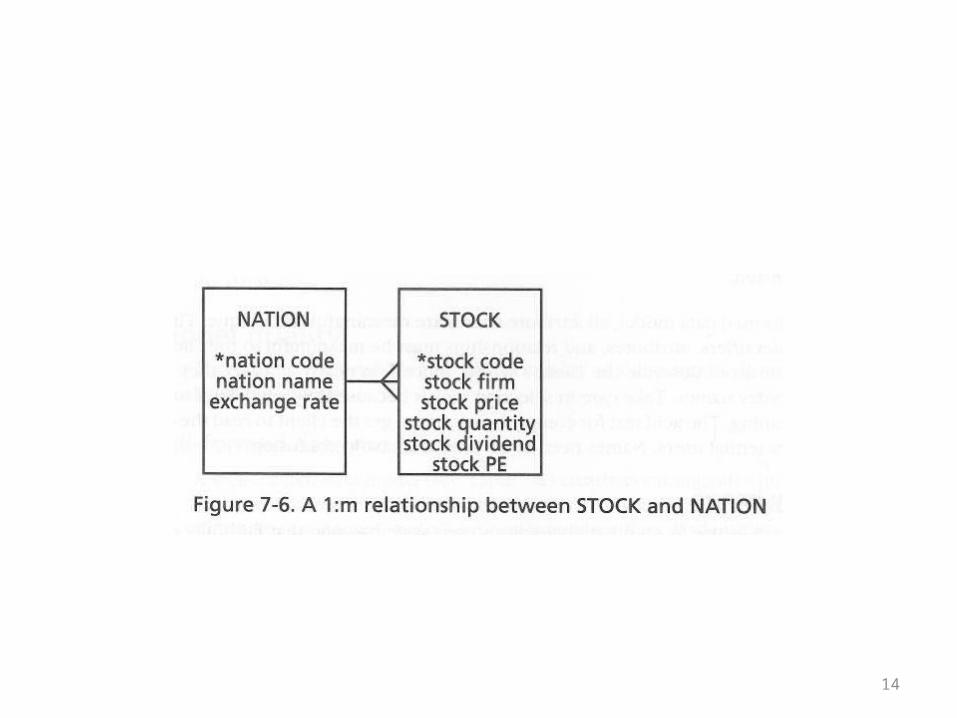
• A simple data model for nations and stocks is given on the next overhead
• Superficially, it seems OK• It could be verbally summarized as “Nations
have stocks”
14
15
• The book now introduces the following additional textual information
• Stocks are listed on stock exchanges (a new entity)
• A nation may have >1 stock exchange• A given stock may be listed on >1 exchange,
but it has 1 home exchange
16
• Stocks can be listed on the exchanges of >1 country
• Notice that the abstraction of a listing is repeated in this description
• That suggests that a listing itself will be an entity
• The next overhead shows a revised model that takes into account the new assumptions
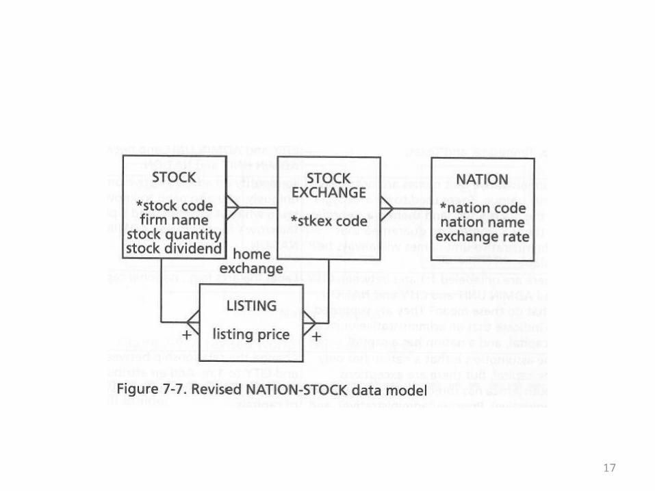
17
18
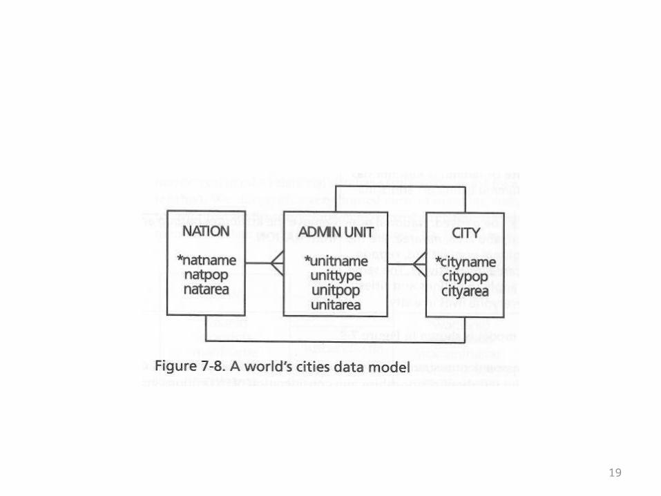
The Geography Example
• Next the book gives a simple example that’s supposed to model the relationships between nations, administrative units (states), and cities
• See the next overhead for a straightforward model of this
19
20
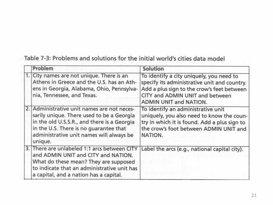
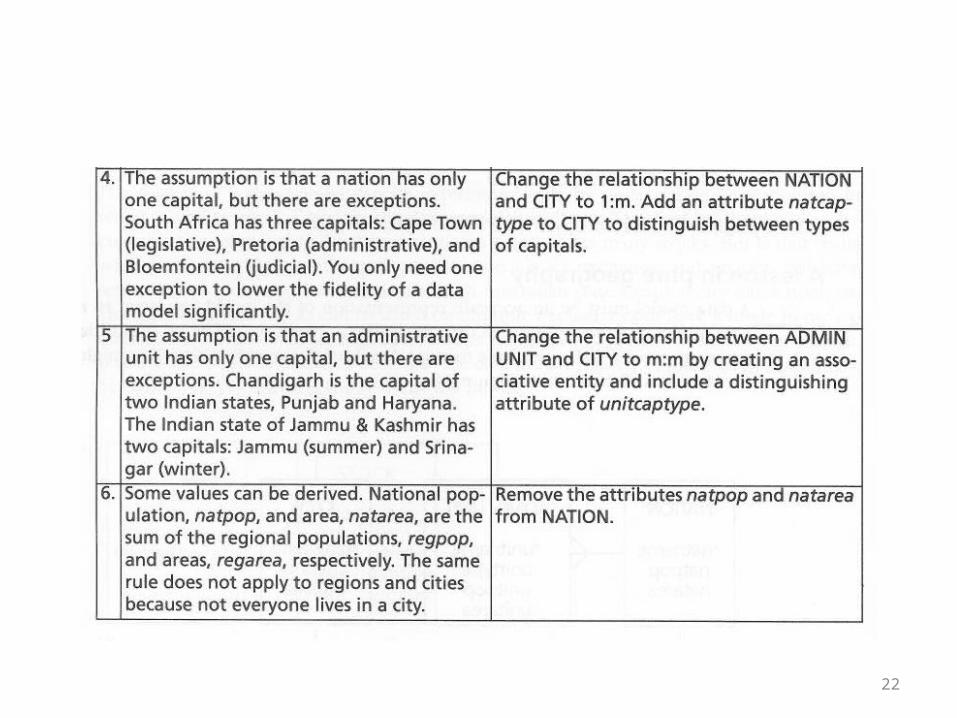
• The book next observes that exceptions are the bane of a good model
• If you presume to model these globally, then your model should accommodate all possible situations
• The book asks, “How many errors can you find in the initial data model?”
• See the table on the following overheads for answers
21
22
23
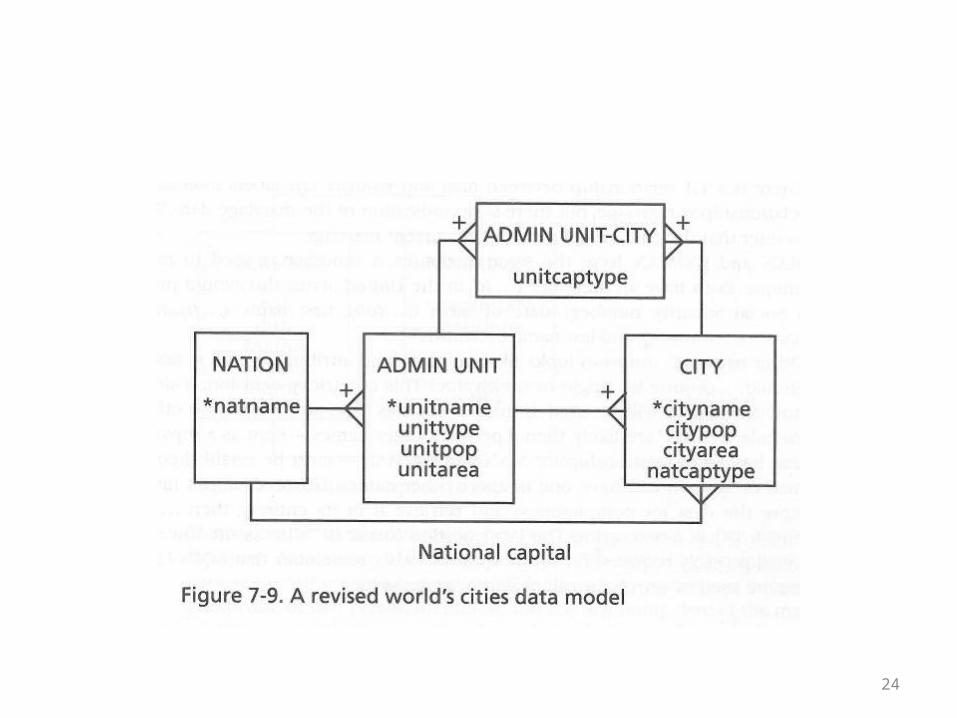
• The next overhead shows a nations, administrative units, cities data model that has been revised to take into account these exceptional cases/errors in the initial model
• This revised model may seem needlessly complex• However, the complexity is not needless• This is an accurate model of the situation that covers all
cases• The initial model was insufficiently complex• It was wrong
24
25
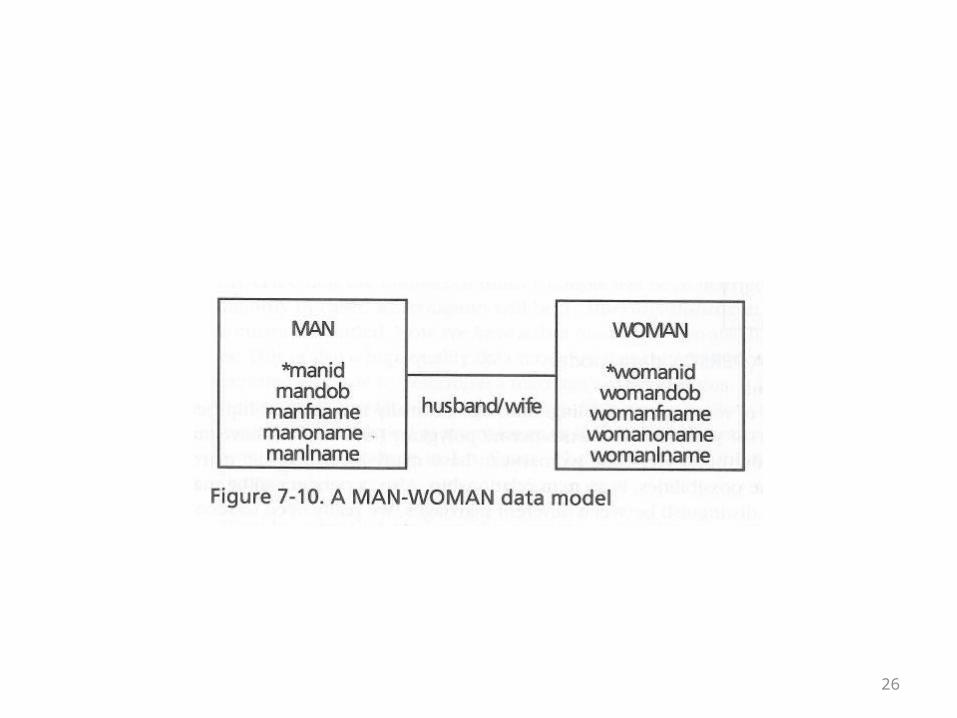
The Women, Men, Marriage, and People Examples
• This topic was brushed on all the way back in unit one
• Capturing the relationships among people is a very common problem that leads to some familiar challenges and design/model choices
• On the following overhead is an ER diagram of the relationship between married men and women
26
27
• The foregoing model is obviously hilariously limited in the kind of relationship it can capture
• In addition, the book points out the following characteristics of the model which might indicate that a different model would be better
• 1. The labeling of the model indicates that this is a marriage, but there is nothing in the fields that spells this out
• In particular, you might think that there would be a date field, a marriage license number, something among the fields that was specific to marriage
28
• 2. The Man and Woman tables have the same set of attributes, different only in their being name manX or womanX
• This might suggest that we are dealing with one entity type, person, rather than two distinct entity types, man and woman
29
• 3. The last observation concerns the fields manoname and womanoname
• These stand for “other” name• As the model stands, a person can only have one other
name• Alternatively, if the other name field is text, it might be
filled with multiple values—not an ideal solution• A complete treatment of people and other names might
introduce another table so that there could be a one-to-many relationship between people and their various names
30
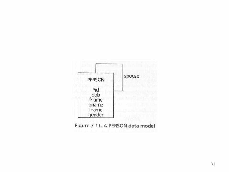
• The book doesn’t solve all of these problems, but it does come up with a second model
• If there were two types to begin with and you combine into one, you frequently get a new field in the result
• A person now has a gender field• Also, the labeling of the relationship could be
made more generic• See the following overhead
31
32
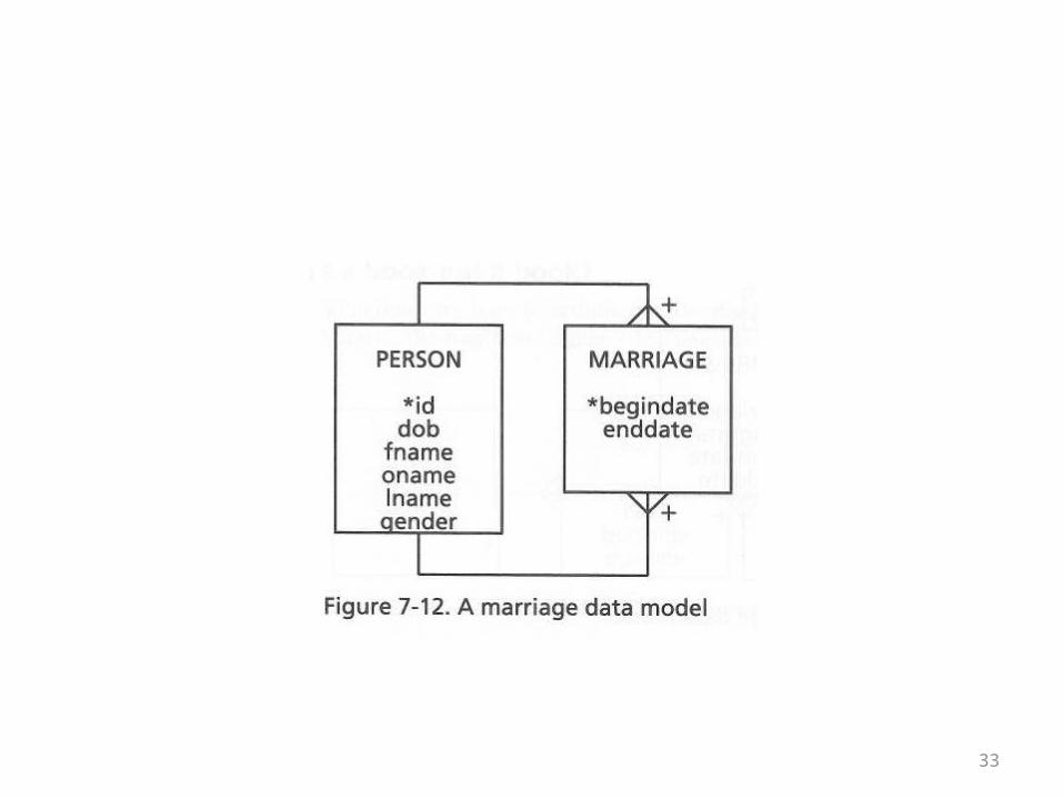
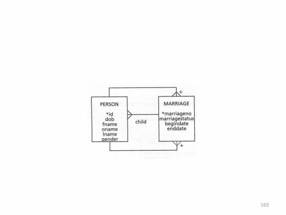
• Next the book tackles the topic of multiple marriages• If you’re dealing with a Person table, then the table
is in a many-to-many relationship with itself• To distinguish between multiple marriages,
potentially between the same partners, beginning and ending date fields can be added to the table in the middle
• See the next overhead for the third version of the model
33
34
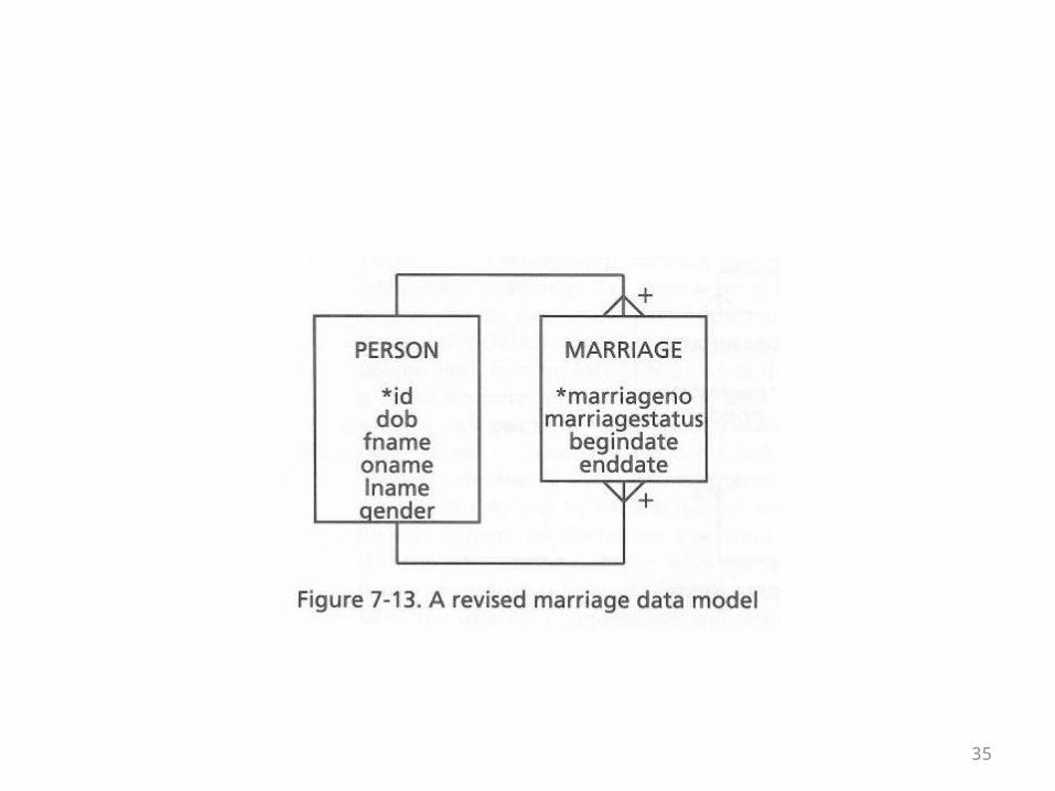
• In the long run, some sort of arbitrary numbering scheme might be desirable
• A marriage license number might work, but the book points out that legally speaking it might also be desirable to record common law marriages
• Notice in general that a lot of data integrity questions start to arise with a model like this
• See the next overhead for the fourth version of the model
35
36
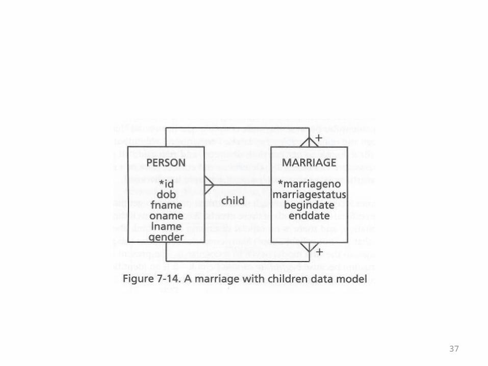
• Next the book considers adding children to the model• Children are modeled as the result of marriage• Of course, this is not always the case• As long as the marriageno field in the person table can
be null, the model accommodates that• Still, it doesn’t allow you to record who a person’s
parents are if the person wasn’t the result of marriage• See the next overhead for the fifth version of the
model
37
38
• The person model could be developed even further
• This model barely scratches the surface of the variety of human relationships
• It is already moderately complex but could become more complex
39
• A model is complete when it contains everything needed in practice for a given problem
• The model is unsuitable if it isn’t complex enough
• It is also unsuitable if it contains detail that isn’t needed
40
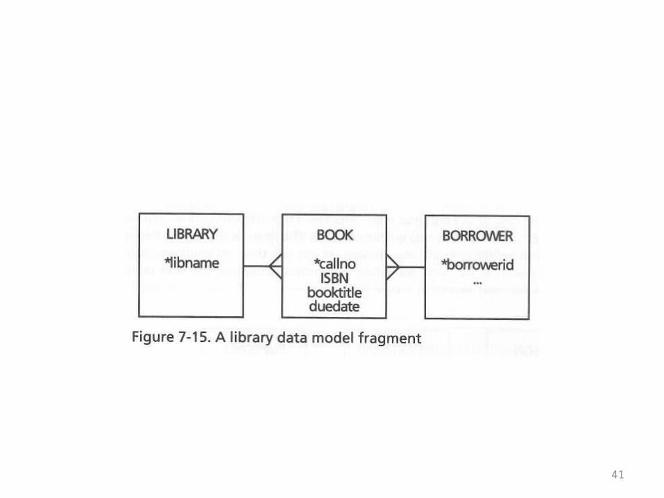
The Book Example
• The book entitles this “When’s a book not a book?”• In other words, the example is an invitation to clarify
what you mean when you refer to entities in a design• Are you referring to individual objects?• Are you referring to kinds of objects?• What elements of a design make it possible to
distinguish between these meanings?• A simplistic initial design is given on the next
overhead
41
42
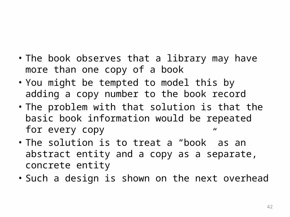
• The book observes that a library may have more than one copy of a book
• You might be tempted to model this by adding a copy number to the book record
• The problem with that solution is that the basic book information would be repeated for every copy
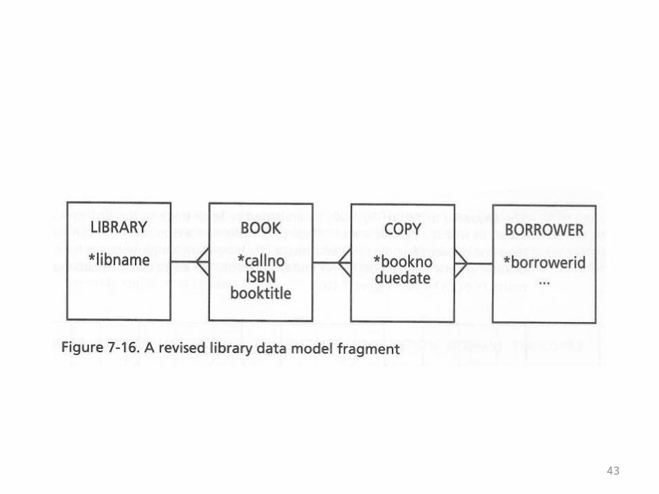
• The solution is to treat a “book” as an abstract entity and a copy as a separate, concrete entity
• Such a design is shown on the next overhead
43
44
• You may have noticed that although the ISBN should be a unique identifier for a book (not a copy) it is not used as a primary key in these designs
• The problem is that books before a certain date did not have ISBN’s
• Also, you may have hand-crafted modern books that weren’t commercially published and don’t have ISBN’s
45
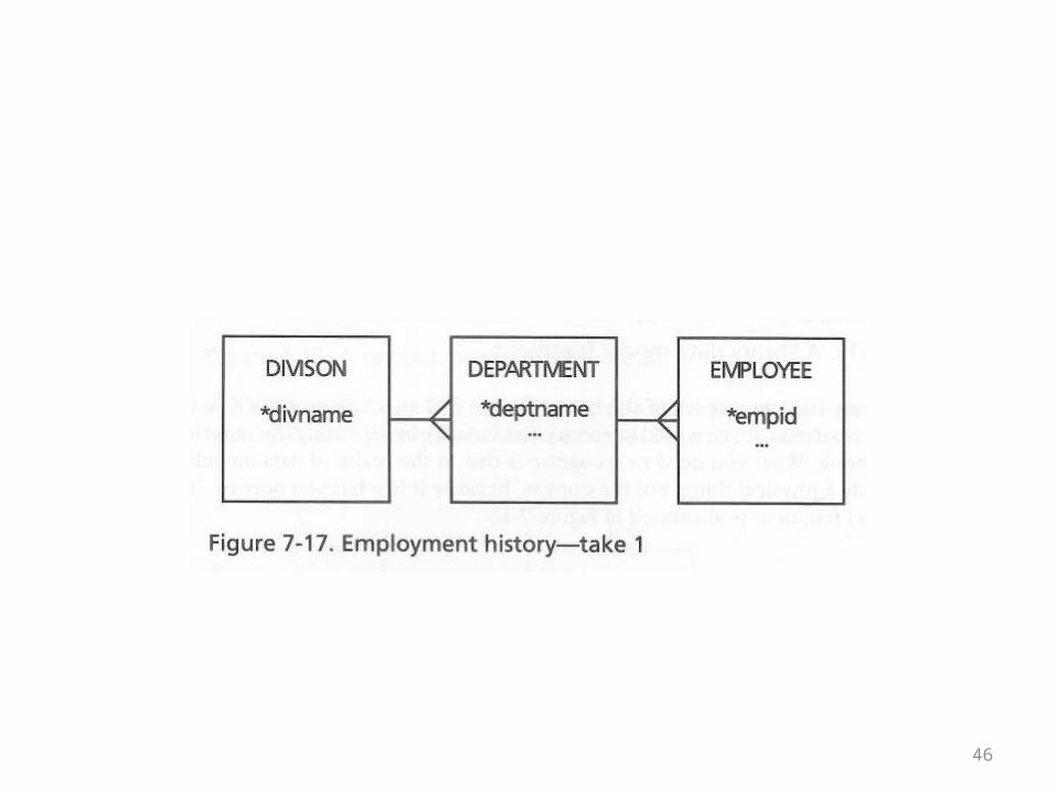
The Employment History Example
• This example starts out simply enough• A given company has divisions• The divisions have departments• Departments have employees• This is shown in the ER diagram on the next
overhead
46
47
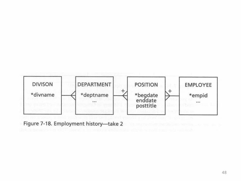
• Next, the author observes that over time a given employee may hold different positions
• These positions may be in different departments• Like marriages, the distinguishing features of
positions may include a beginning and ending date
• This is shown in the ER diagram on the next overhead
48
49
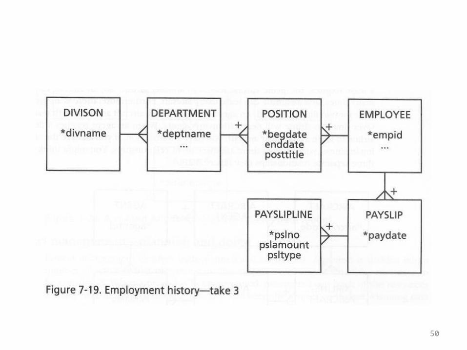
• Next the author introduces the concept of a payslip into the record-keeping that the model includes
• It’s not fully fleshed out in the next example, but when you look at the diagram you may have an inkling that the treatment of payslips is reminiscent of the treatment of line items
• This is shown in the ER diagram on the next overhead
50
51
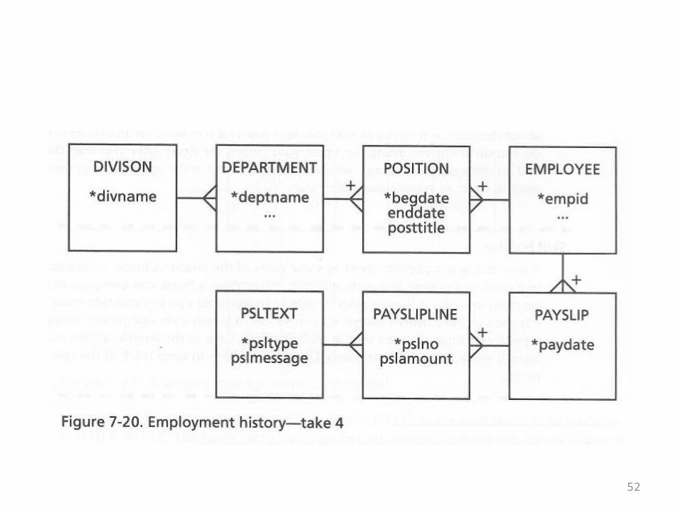
• The final design treats payslips exactly like the line item example
• A payslip is like a bill of sale• Pay slip text is like an item• The table in the middle, PaySlipLine, is like LineItem• The pk of PaySlipLine is the concatenation of the pk of
Payslip embedded as a fk, plus a pay slip number (payslipno)
• The pk of PslText is embedded separately as a fk• This is shown in the ER diagram on the next overhead
52
53
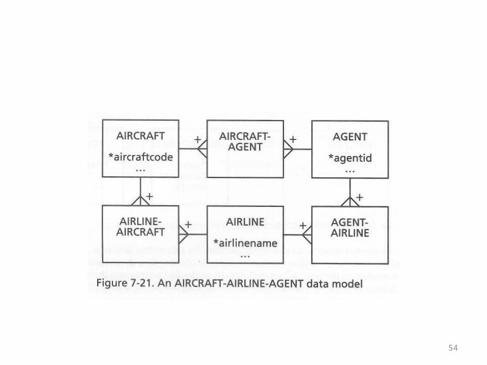
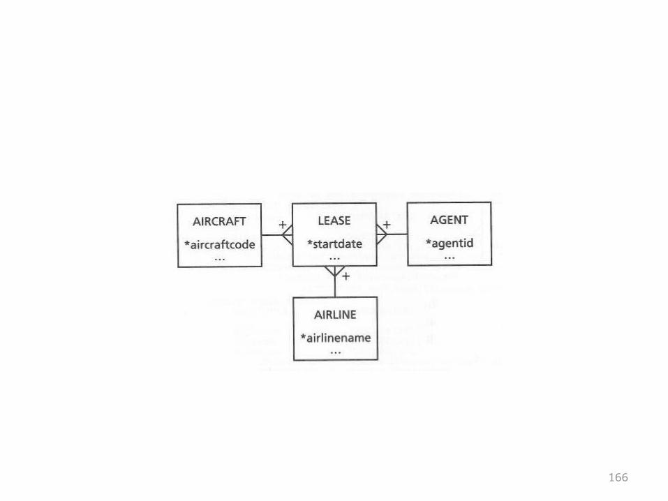
The Aircraft Leasing Example
• In the previous set of overheads the first design containing a cycle cropped up
• This example also contains a cycle• There are three base tables and three tables in the
middle• Each of the base tables is in a many-to-many
relationship with each other• Overall, the tables are in a many-to-many-to-may
relationship• This is shown in the ER diagram on the next overhead
54
55
• How to properly model a situation becomes an important question in the next chapter, on normalization
• In the meantime, the following observation can be made:
• An aircraft lease is an abstract entity that seems to be part of the business problem
• However, it doesn’t appear in the design• This isn’t just a problem in a theoretical sense
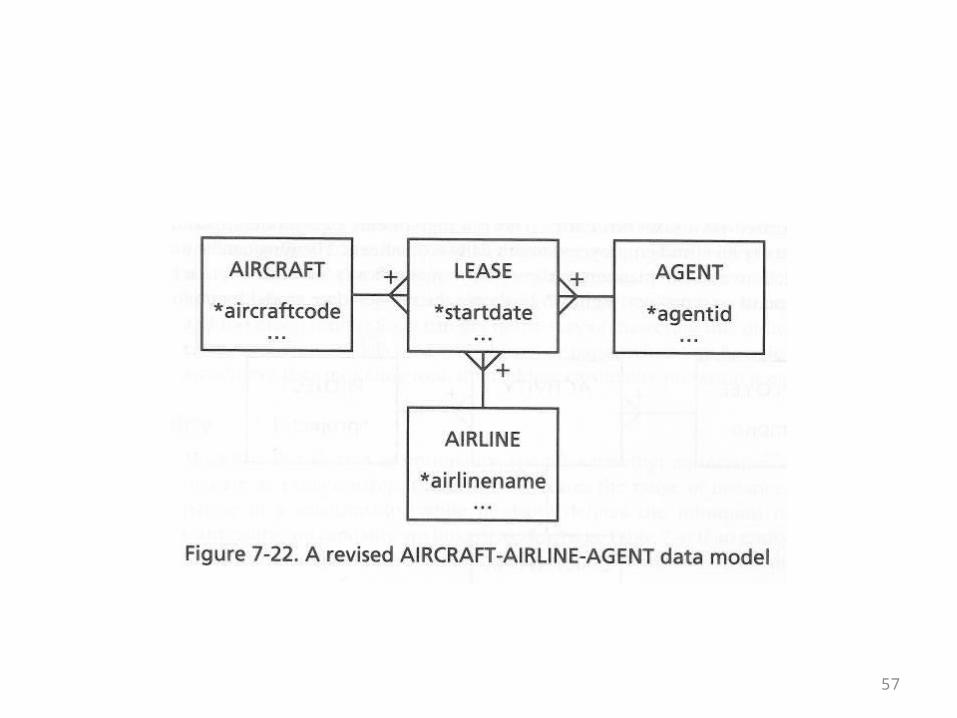
56
• First of all it’s clear that in order to get complete information about a lease from this design a 6-way join would be needed
• That’s inconvenient• Also, leases themselves may have attributes like
starting and ending dates• There is no place to record them• An improved, star-like design for the problem is
shown on the next overhead
57
58
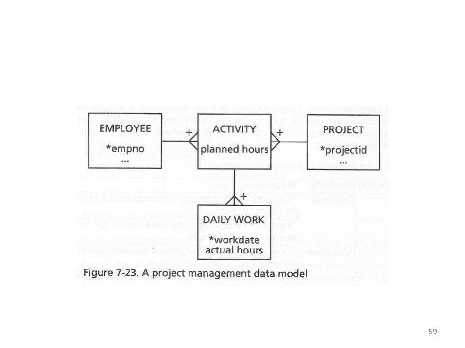
The Project Management Example
• This example addresses the question of where something could or should be modeled
• It impinges on the question of how the model has to be changed to capture a more detailed business situation
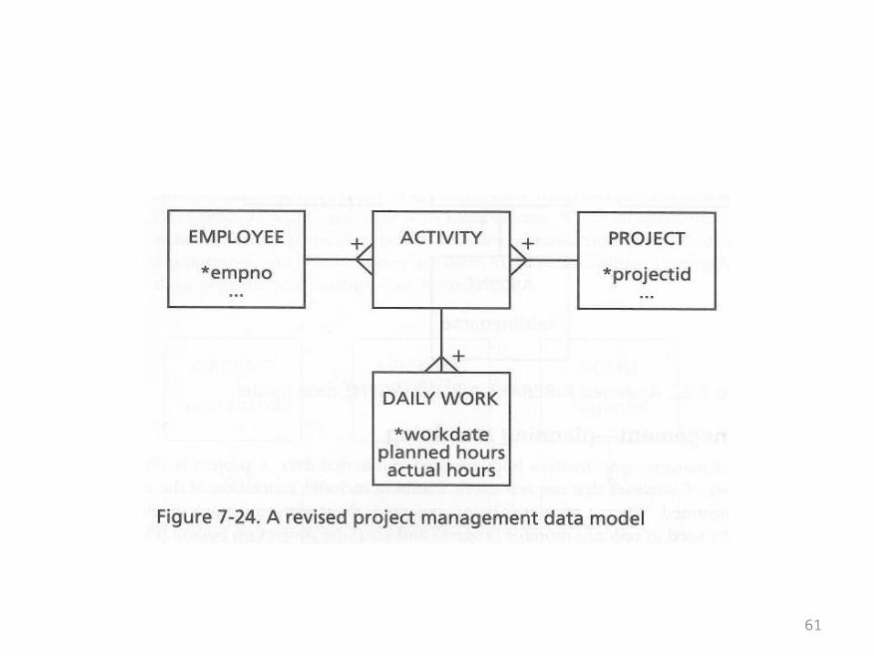
• The first model is given on the next overhead• It should be relatively self-explanatory
59
60
• Now consider the altered model on the following overhead
• The planned hours attribute has been moved from the Activity entity to the Daily Work entity
• This small change in location of a field has a clear and logical outcome
• The planning of project hours is done on a daily basis, not an activity basis
61
62
Cardinality and Modality
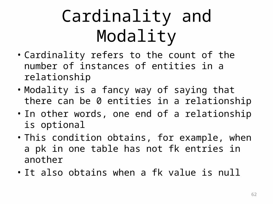
• Cardinality refers to the count of the number of instances of entities in a relationship
• Modality is a fancy way of saying that there can be 0 entities in a relationship
• In other words, one end of a relationship is optional
• This condition obtains, for example, when a pk in one table has not fk entries in another
• It also obtains when a fk value is null

63
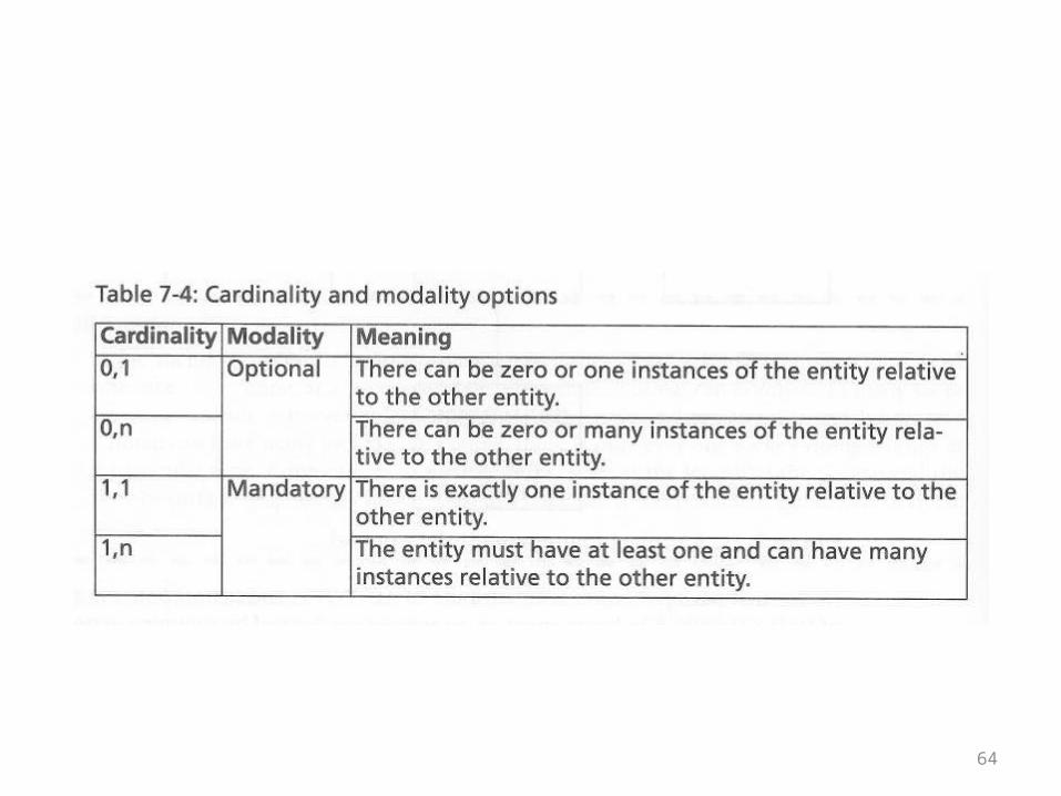
• The book gives the table shown on the next overhead summarizing cardinality and modality
64
65
• The author now enhances the notation for ER diagrams
• Unlike UML, it is not customary to mark actual digits at the ends of crows’ feet
• Instead, a short vertical bar marks the end of a relationship where an instance of an entity is mandatory
• An “o” marks the end of a relationship where an instance of an entity is optional
66
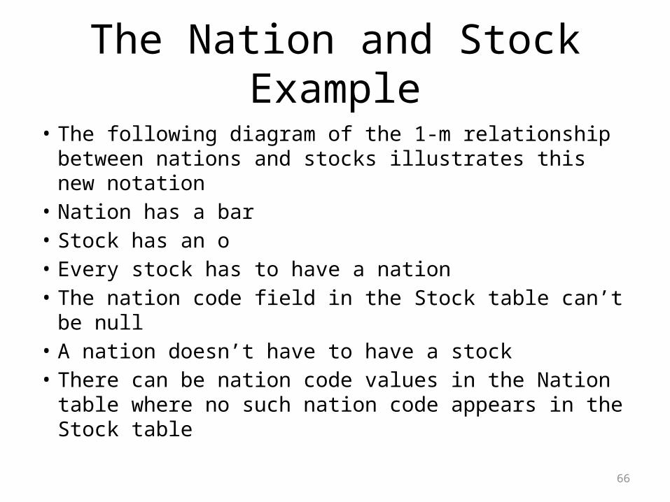
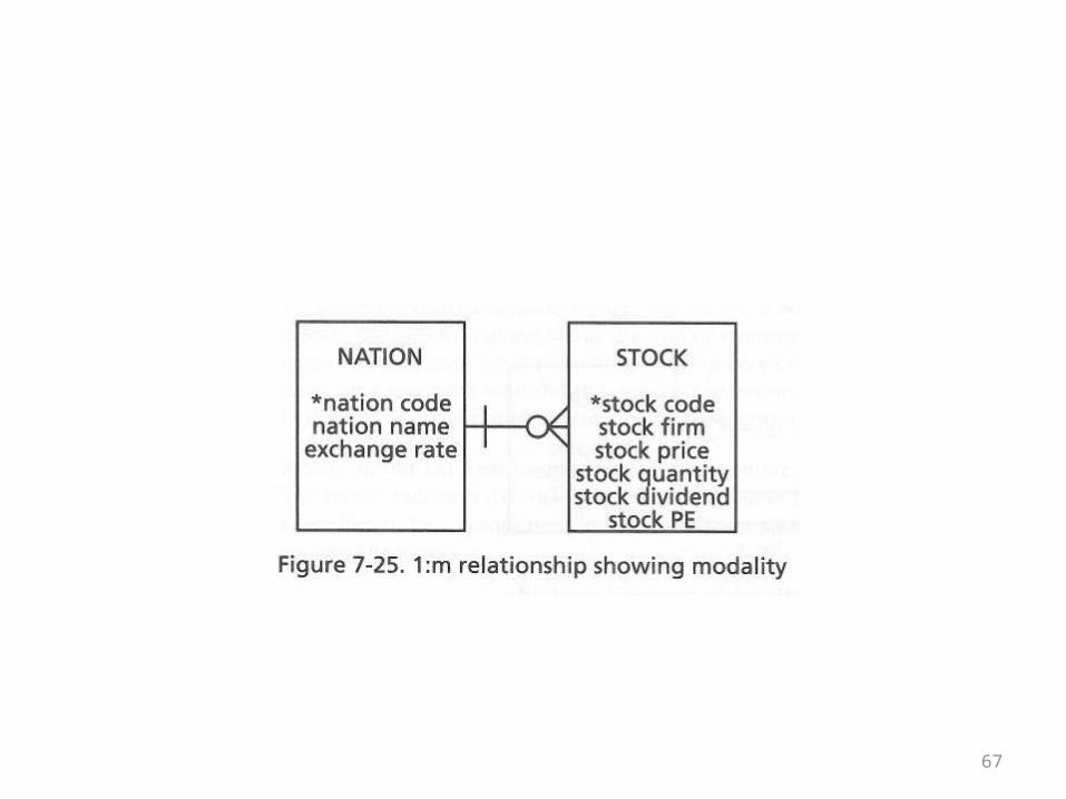
The Nation and Stock Example
• The following diagram of the 1-m relationship between nations and stocks illustrates this new notation
• Nation has a bar• Stock has an o• Every stock has to have a nation• The nation code field in the Stock table can’t be null• A nation doesn’t have to have a stock• There can be nation code values in the Nation table
where no such nation code appears in the Stock table
67
68
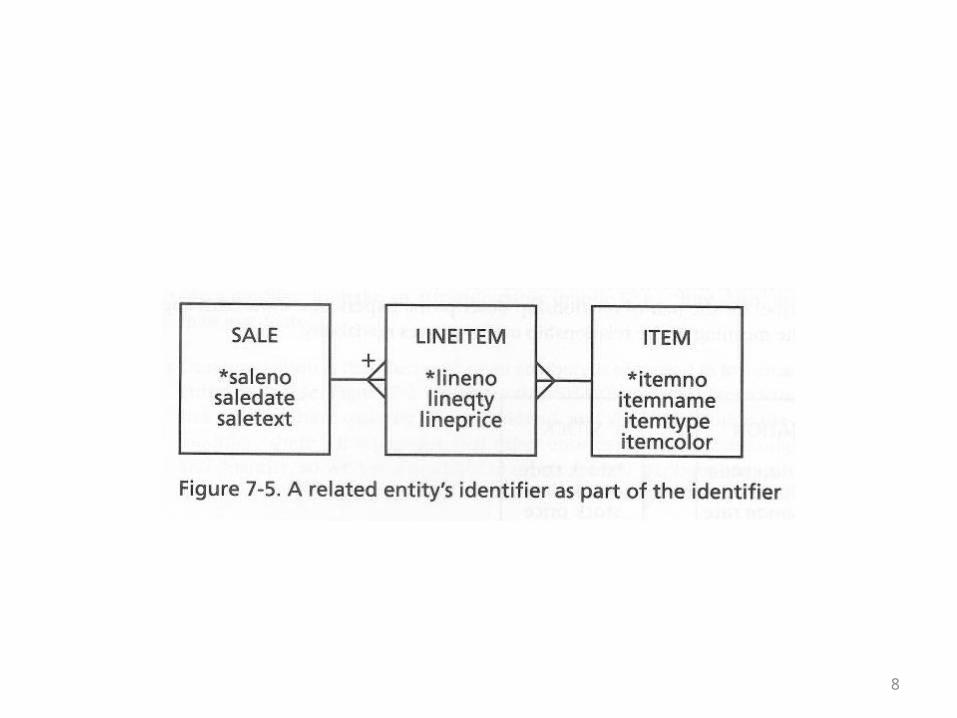
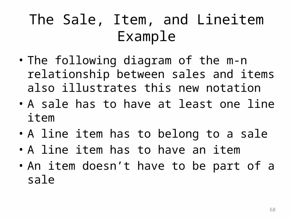
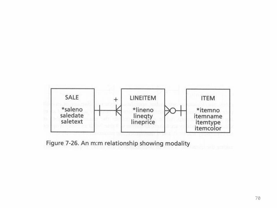
The Sale, Item, and Lineitem Example
• The following diagram of the m-n relationship between sales and items also illustrates this new notation
• A sale has to have at least one line item• A line item has to belong to a sale• A line item has to have an item• An item doesn’t have to be part of a sale
69
• These verbal statements can be translated into null/not null and existence/non-existence requirements for fields and rows in tables
• The new thing illustrated by this example is that if you have a row for a sale in the Sale table, the ER diagram now states that it has to have a corresponding record in the Lineitem table
• This is not something that can be enforced by the database using referential integrity, for example
• It is a new kind of data integrity constraint
70
71
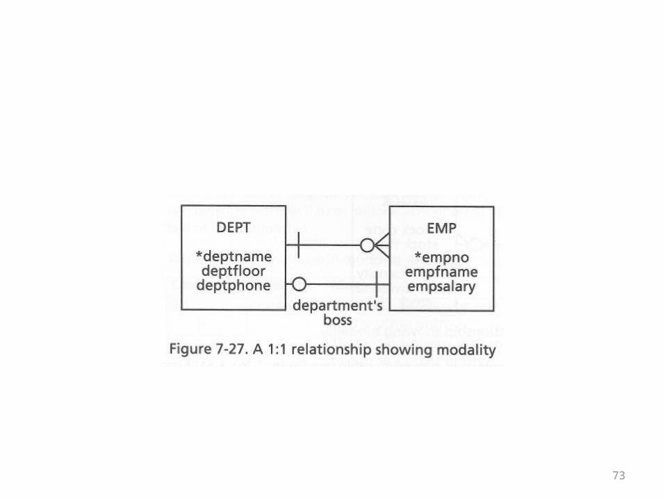
The Department and Employee Example
• The following diagram of the 1-m and 1-1 relationships between departments and employees also illustrates this new notation
• An employee has to have a department• A department doesn’t have to have employees• A department has to have a boss• An employee doesn’t have to be the boss of a
department
72
• It is worth paying close attention to the 1-1 relationship
• It looks a little odd to have a line with no crow’s foot with a bar at one end and an o at the other
• Recall that in order to reduce the number of nulls, the 1-1 relationship was captured by embedding the pk of Employee as a fk in Department
• The notation means that the fk can’t be null• It also means that not every pk of Employee has to
appear as a fk value
73
74
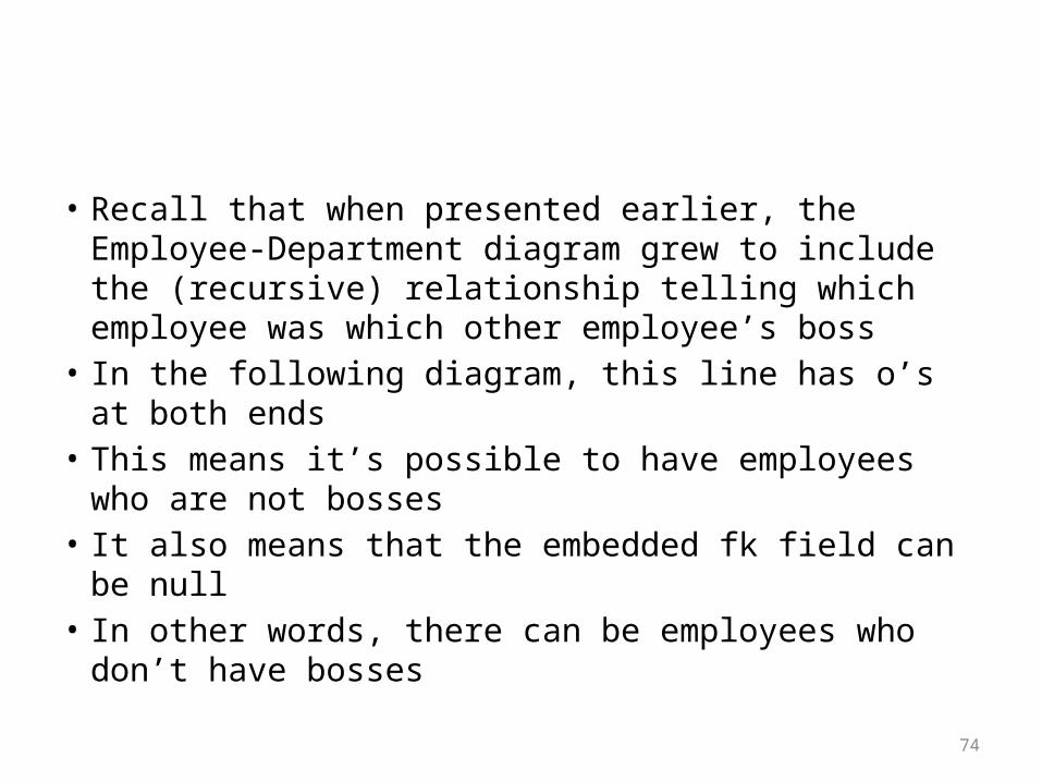
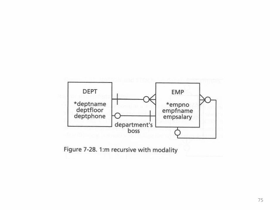
• Recall that when presented earlier, the Employee-Department diagram grew to include the (recursive) relationship telling which employee was which other employee’s boss
• In the following diagram, this line has o’s at both ends• This means it’s possible to have employees who are not
bosses• It also means that the embedded fk field can be null• In other words, there can be employees who don’t
have bosses
75
76
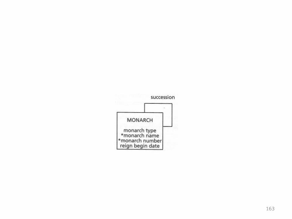
The Monarch Example
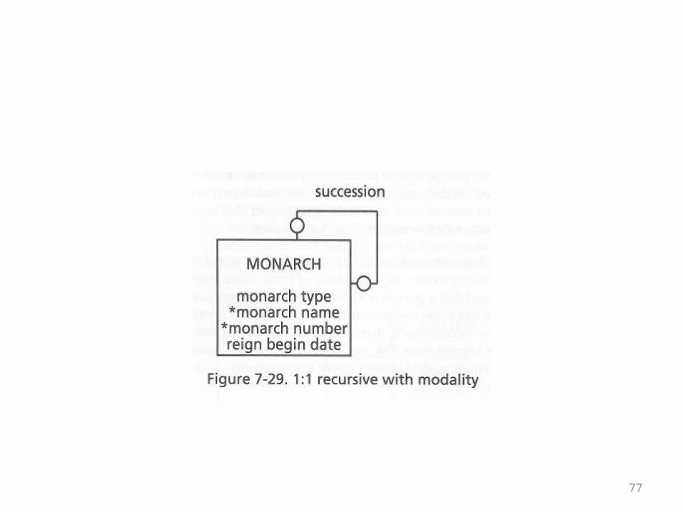
• The monarch succession relationship can also be marked for modality
• The first monarch would have no predecessor• The current monarch would have no successor
(yet)• Both ends of the relationship are optional• This is shown in the ER diagram on the
following overhead
77
78
The Product Assembly Example
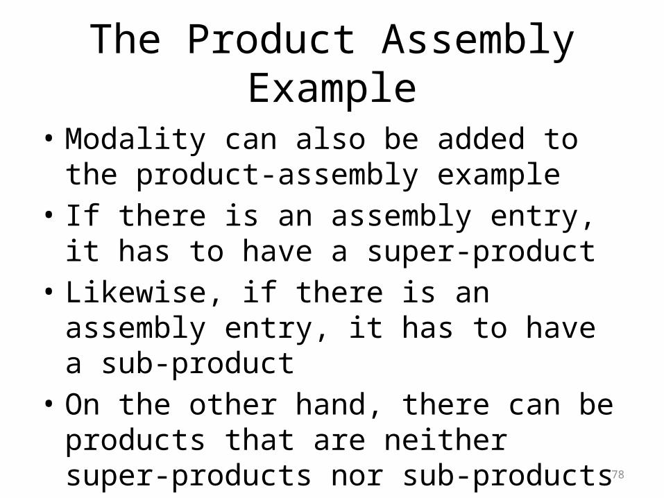
• Modality can also be added to the product-assembly example
• If there is an assembly entry, it has to have a super-product
• Likewise, if there is an assembly entry, it has to have a sub-product
• On the other hand, there can be products that are neither super-products nor sub-products
79
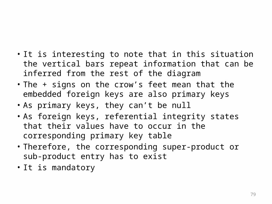
• It is interesting to note that in this situation the vertical bars repeat information that can be inferred from the rest of the diagram
• The + signs on the crow’s feet mean that the embedded foreign keys are also primary keys
• As primary keys, they can’t be null• As foreign keys, referential integrity states that their values
have to occur in the corresponding primary key table• Therefore, the corresponding super-product or sub-product
entry has to exist• It is mandatory

80
81
Entity Types
• The author categorizes entities into the following types:
• Independent• Weak or dependent• Associative• Aggregate• Subordinate
82
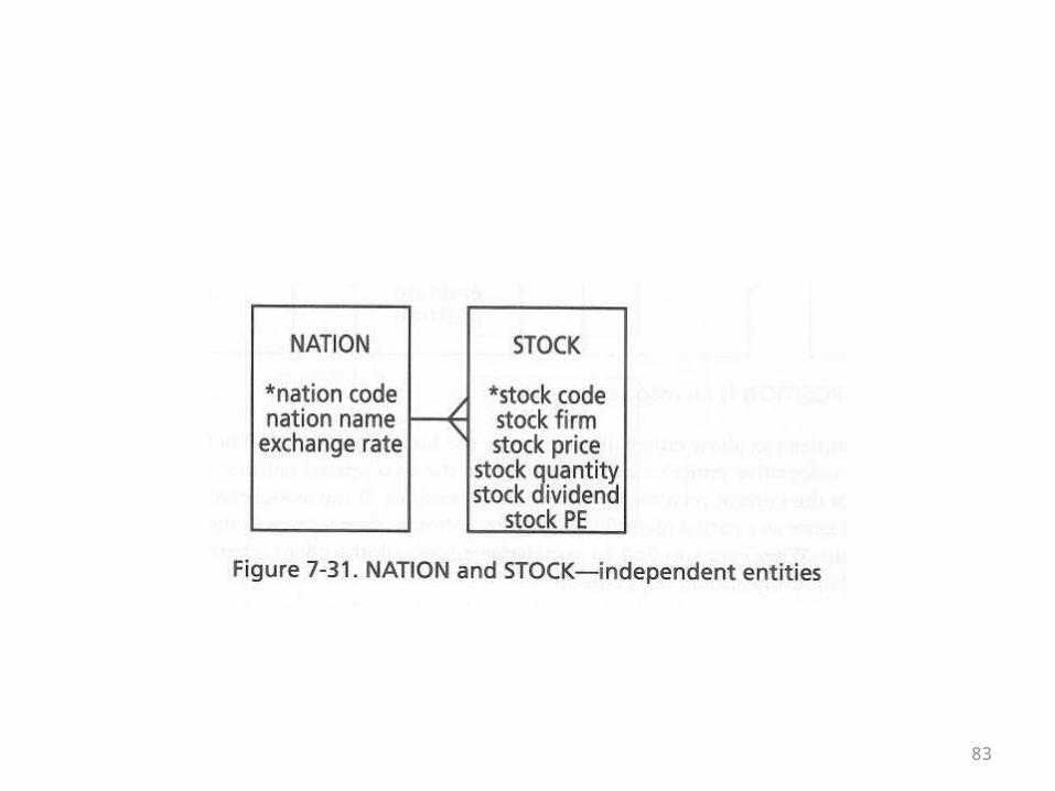
Independent entities
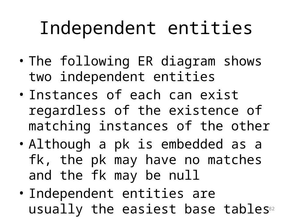
• The following ER diagram shows two independent entities
• Instances of each can exist regardless of the existence of matching instances of the other
• Although a pk is embedded as a fk, the pk may have no matches and the fk may be null
• Independent entities are usually the easiest base tables to recognize in a problem domain
83
84
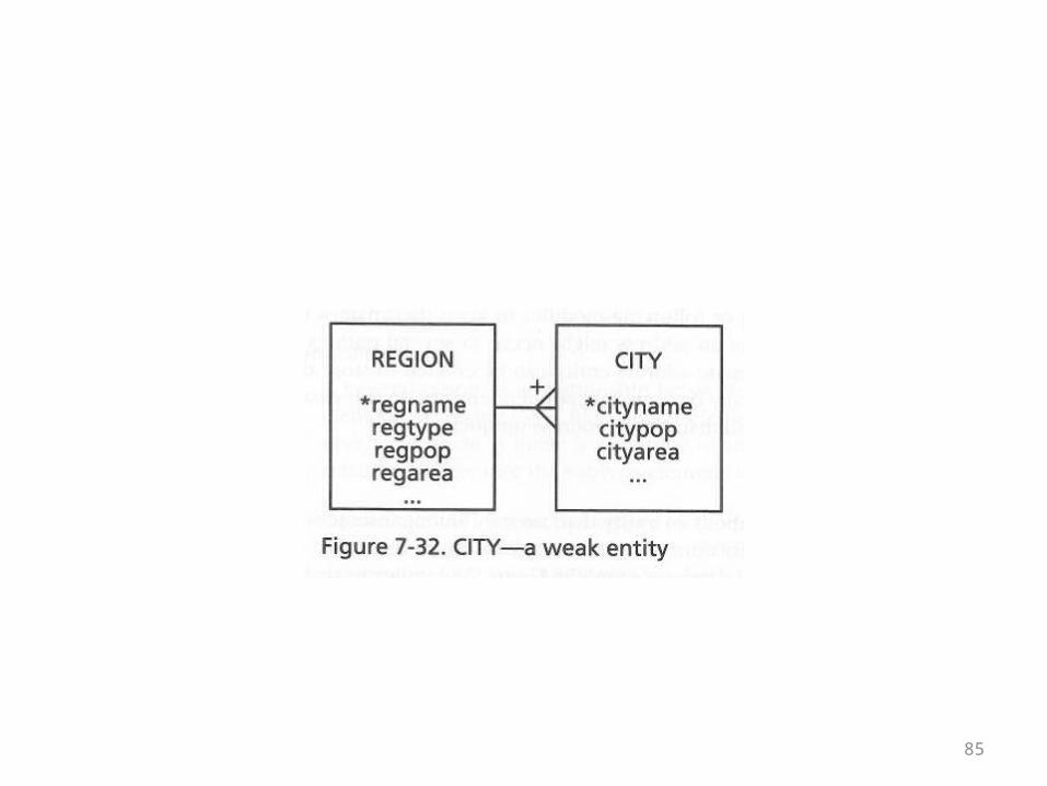
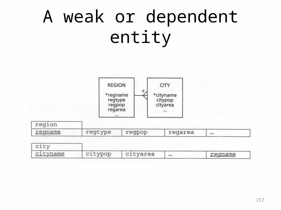
Weak or Dependent Entities• A weak entity is one where the pk of another table is
embedded as a fk in it• And the fk is part of the primary key of the dependent table• Because the pk of the weak entity can’t be null, in its role as
a fk, that field has to have a corresponding pk value in the other table
• In other words, an instance of a dependent entity simply can’t exist without the existence of a matching instance in the other table
• In the following ER diagram, cities can’t exist without their corresponding regions
85
86
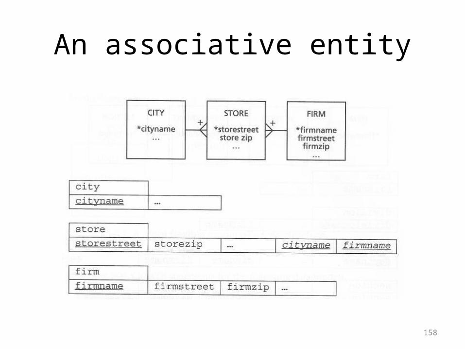
Associative Entities
• Associative entities have already been explained
• This is an alternative name for the table in the middle
• The table in the middle may or may not have a concatenated key
• It may or may not have attributes of its own
87
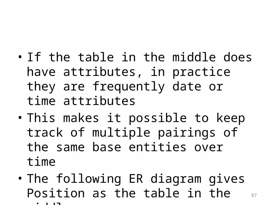
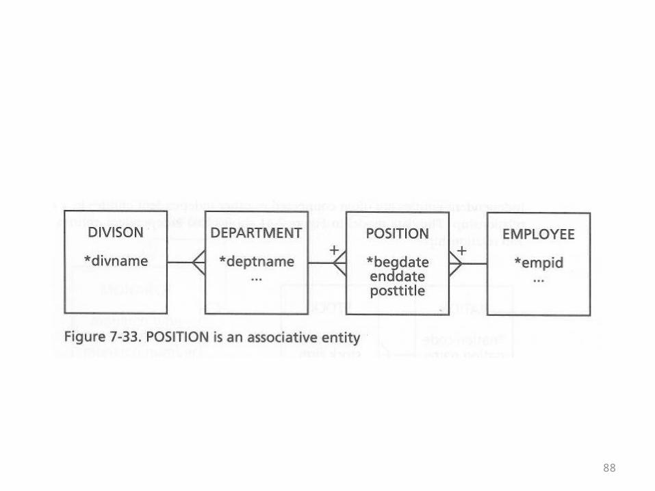
• If the table in the middle does have attributes, in practice they are frequently date or time attributes
• This makes it possible to keep track of multiple pairings of the same base entities over time
• The following ER diagram gives Position as the table in the middle
88
89
Aggregate Entities
• The book doesn’t have a diagram for this concept
• It explains it verbally• Customers and suppliers are two different
entities which might both have addresses• Address information could be broken out of
both
90
• Once it is broken out, there is no reason to have two different kinds of address
• And address is an address, and both the Customer and Supplier tables could be in a relationship with an address (address line…) table
• The reason there is no diagram is that once model analysis is complete, the aggregate table simply becomes another base table
91
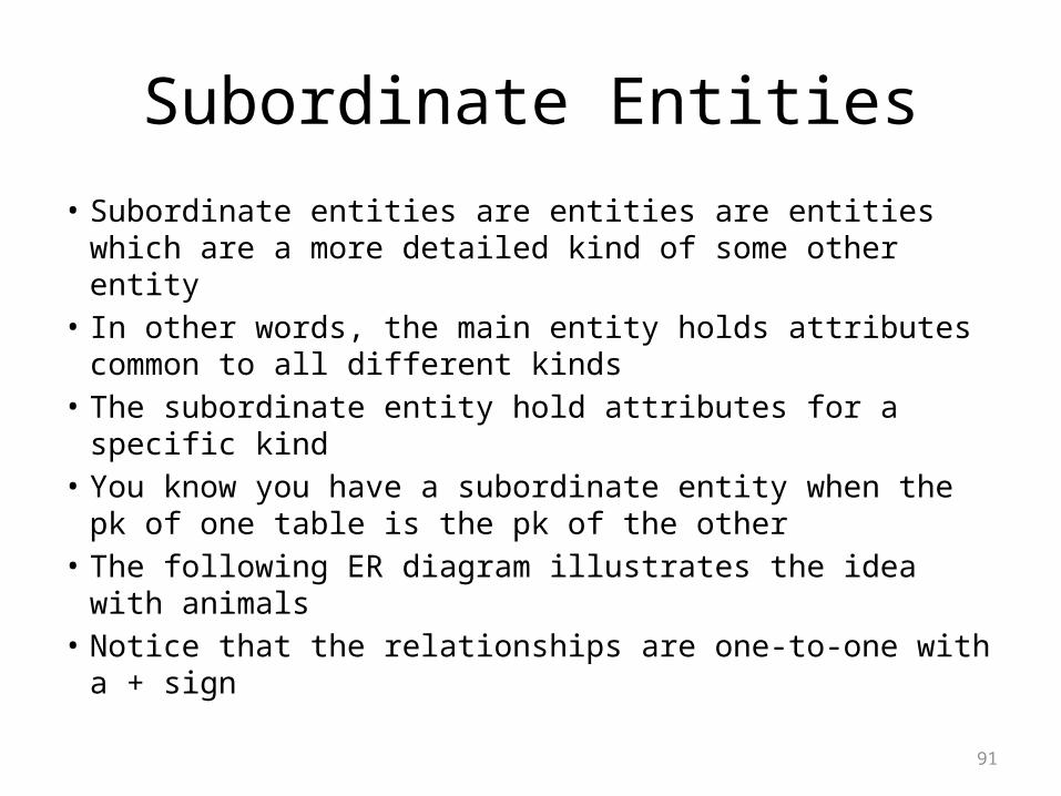
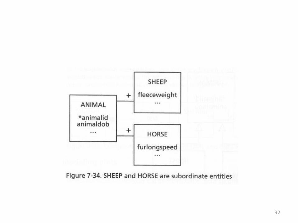
Subordinate Entities• Subordinate entities are entities are entities which are a
more detailed kind of some other entity• In other words, the main entity holds attributes common
to all different kinds• The subordinate entity hold attributes for a specific kind• You know you have a subordinate entity when the pk of
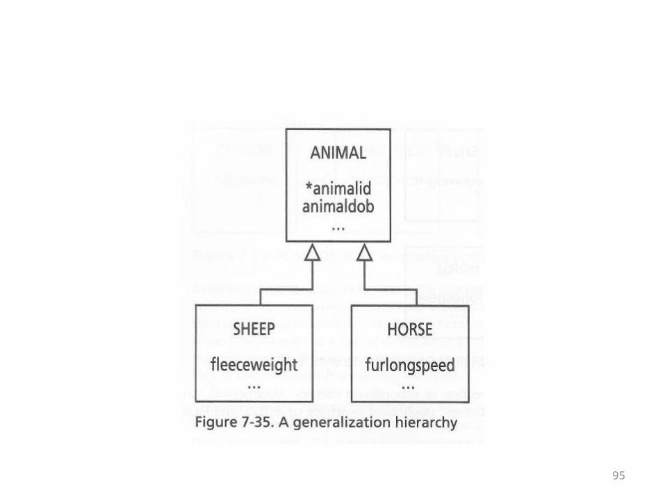
one table is the pk of the other• The following ER diagram illustrates the idea with animals• Notice that the relationships are one-to-one with a + sign
92
93
Generalization and Aggregation
• First, keep in mind that the use of the term aggregation here is different from its use in the phrase “aggregate entity”
• Also note that the author is now introducing object-oriented ideas
• This makes it possible to compare ER notation with UML notation
94
• The following UML diagram captures the relationship between animals, sheep, and horse that was illustrated in the previous ER diagram
• Animal is a generalization of the other two kinds of animals
• Together, the different kinds of animals form a hierarchy of the type “is-a” or “is-a-kind-of” which should be familiar from the object-oriented world
95
96
Aggregation
• Aggregation and composition are usually treated together in object-orientation
• Aggregation captures a “has-a” or containment relationship
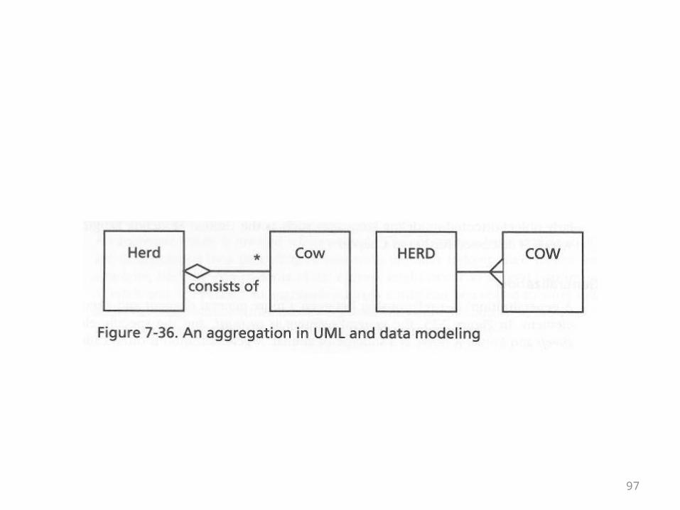
• In UML it is symbolized by a diamond• The diamond is less intuitive than the crow’s
foot, but they are roughly equivalent• This is illustrated on the next overhead
97
98
Aggregation and Composition; One-to-Many and Many-to-Many Relationships
• In UML, the term aggregation is usually described as a simple “has-a” relationship and is symbolized with a white diamond
• Composition is usually described by a phrase like, “the parts can’t exist without the whole” and is symbolized by a black diamond
• These concepts translate at least in part into relational database concepts and ER diagrams
99
• The translation between object-oriented and relational isn’t perfect though
• Object-oriented code can have references• All relationships in the relational model are
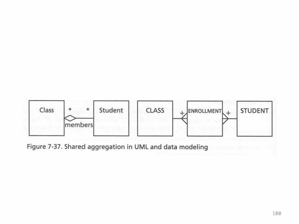
captured by the values of fields• The diagrams on the next overhead show the
relationship between classes and students• They will be followed by commentary
100
101
• In the UML diagram a white diamond is used• Students can exist without enrolling in any
classes• More importantly, in the UML diagram there is
no Enrollment class• A many-to-many relationship can be captured
using references alone
102
• In the ER diagram there is an Enrollment class to capture the many-to-many relationship
• This is a classic table in the middle with a concatenated primary key, indicated by the + signs
• As such, enrollment records are dependent
103
• Enrollment records cannot exist without corresponding student and class records
• If there were an Enrollment class in the O-O model, it would be an example of composition, not aggregation
• For further explanation, see the next example
104
• Next the book illustrates the relationship between students an aptitude tests
• The key to the diagrams is the relationship label “taken”
• Aptitude tests themselves can exist without students
105
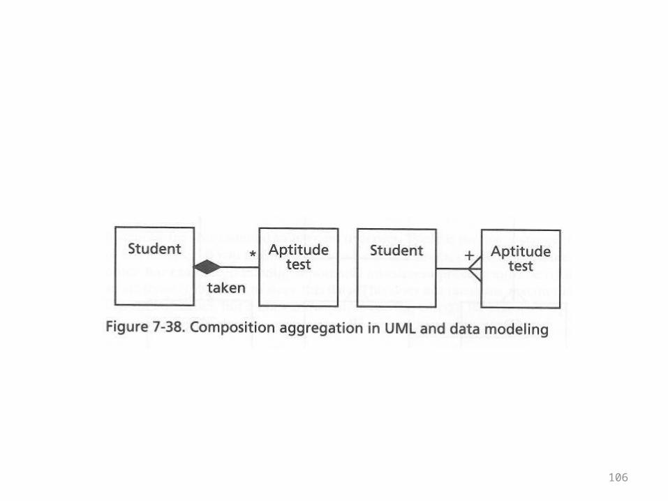
• However, the class/entity labeled Aptitude test actually means a specific aptitude test score
• The diagram is given on the next overhead• More explanations follow it
106
107
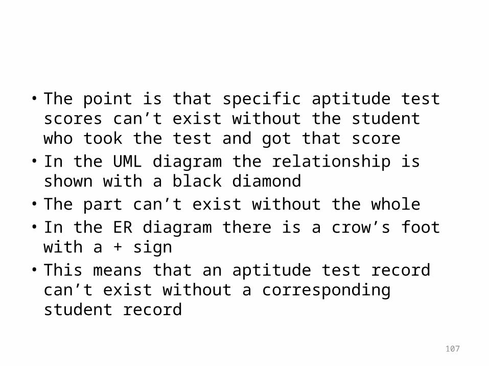
• The point is that specific aptitude test scores can’t exist without the student who took the test and got that score
• In the UML diagram the relationship is shown with a black diamond
• The part can’t exist without the whole• In the ER diagram there is a crow’s foot with a + sign• This means that an aptitude test record can’t exist
without a corresponding student record
108
Data Modeling Hints
• The book next addresses these subpoints:• The rise and fall of a data model• Identifier• Position and order• Attributes and consistency• Names and addresses• Single instance entities
109
• Picking words• Synonyms• Homonyms• Exception hunting• Relationship labeling• Keeping the data model in shape• Used entities
110
The rise and fall of a data model
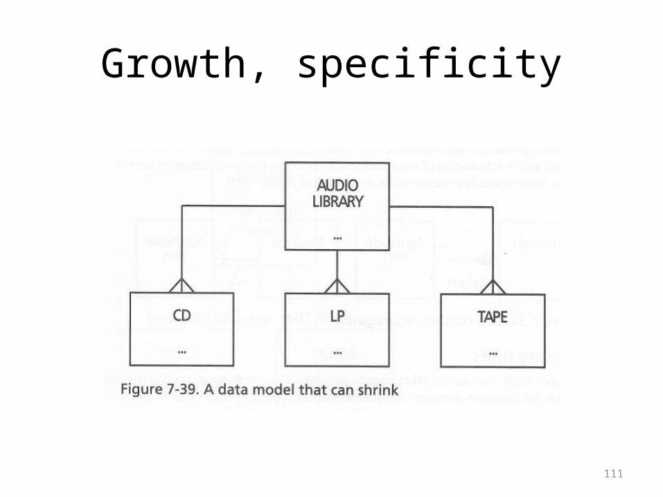
• The book points out that a model will both grow and shrink as it develops
• Discovering new entities will cause it to grow• Trying to handle greater specificity will cause it to
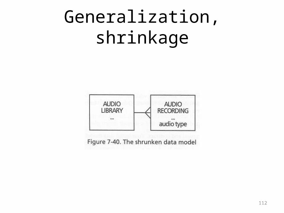
grow• Generalization happens when you recognize useful
commonality• This will cause a model to shrink in a useful way• Consider the diagrams on the following overheads
111
Growth, specificity
112
Generalization, shrinkage
113
Identifier
• The basic rule, except in cases where a simple concatenated key works:
• If there is no obvious identifier (pk), simply make up an arbitrary one
• Consecutive numbering by entry order would be a simple choice
• Notice that packages like Access have features like this
114
• There is an irony to such “helpful” features• They are most likely to be used by people who
don’t even know what a pk is, and they will end up making a confusing mess
• For more informed users, the feature isn’t really necessary, and they’re more likely to want full control over the values entered anyway
115
Position and Order
• The concepts of position and order apply to both the ER diagram of the model and the contents of tables
• The general rule for presenting a model is to be organized
• The most important base entities might appear in the center, at the top, starting at the left—somewhere, anywhere where they aren’t hidden as afterthoughts
• Also, arranging things so that lines don’t cross is important for understanding
116
• The important point is that all entities and relationships be correctly identified
• Similarly, there is no required order to the attributes in an entity
• However, common sense dictates being consistent, putting the pk first, listing more important attributes nearer the top
• In the author’s notation, fk’s don’t appear• I still recommend that they be included, marked with
fk so that they can’t be overlooked
117
• As usual, the rows in a table are not stored in sorted order
• When picking fields for a table you want to keep in mind any ordering that you might eventually want produced by a query
• There has to be a field for the ORDER BY if you want the data presented in that order
118
• On the next overhead the monarch data model is shown again
• There is an implicit ordering to the data based on the values
• It is interesting to consider whether you could write a query that would show the monarchs in succession order
• It seems that this would have to procedural, like the recursive query to find all products in a given product
• The solution to the problem would be a design where the monarchs were simply numbered in order
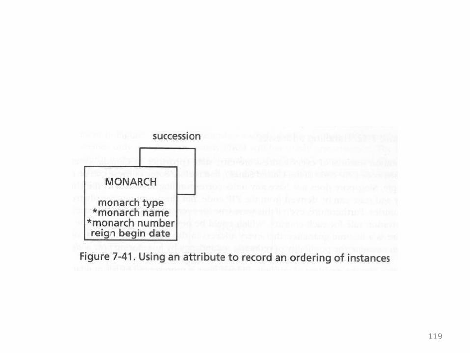
119
120
Attributes and consistency
• In simple terms, if you use the same field name in different tables, it should have the same meaning in the different tables
• Within a single table, the field should also have exactly the same meaning for every row
• The book’s example of what shouldn’t be done with attributes is outlined on the next overhead
121
• Let there be an attribute “stock info” that stores either the stock’s price to earning ratio or its return on investment
• Which value is held in that field is determined by whether the value 1 or 2 appears in another field named “stock info code”
• This is very unfortunate• One field in a table now depends on another• The meaning of the dependent field varies from record
to record
122
Names and addresses
• Names and addresses frequently occur in databases• Although not incredibly hard, their treatment is
usually a little more complex than what you might think at first glance
• There are several basic rules that apply• Have you subdivided into sufficiently small fields?• Can you handle multiple occurrences?• Can you construct something that consists of
multiple parts?
123
• Although SQL has string operators that allow you to form queries based on subparts of fields, it is not wise to depend on this
• For example, in the long run it is easier and more logical to have first name, middle name, and last name fields in place of one monolithic name fields
124
• The book also mentions the question of including titles with names (Mr., Mrs., etc.)
• There is also the question of suffixes (jr., III, and so on)• There are those people who have multiple given names
(George Herbert Walker Bush)• There are also those people who have different names
married than when they were single• Or there are people who have changed their names legally or
simply use aliases• The point is that a complete design will handle all of these
cases
125
• The question of addresses is not really more difficult, but it is somewhat less familiar than names
• The fundamental problem is that addresses can take many different forms
• Depending on the organization, an address may be many lines long
• Depending on the country, an address might come in an uncustomary order
126
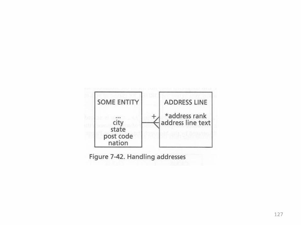
• The handling of addresses was mentioned earlier
• It has something in common with line items and pay slips in its most complete treatment
• The gives the model on the next overhead as a reminder
127
128
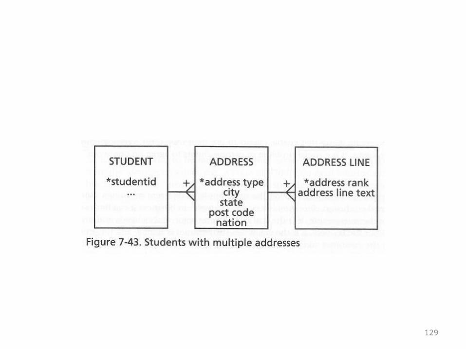
• Finally, people might have more than one address
• A home address vs. a school address• A mailing address vs. a residential address• This doesn’t add a great deal of complexity—
it’s just a one-to-many relationship• The book gives the ER diagram on the
following overhead to illustrate
129
130
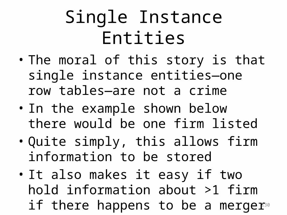
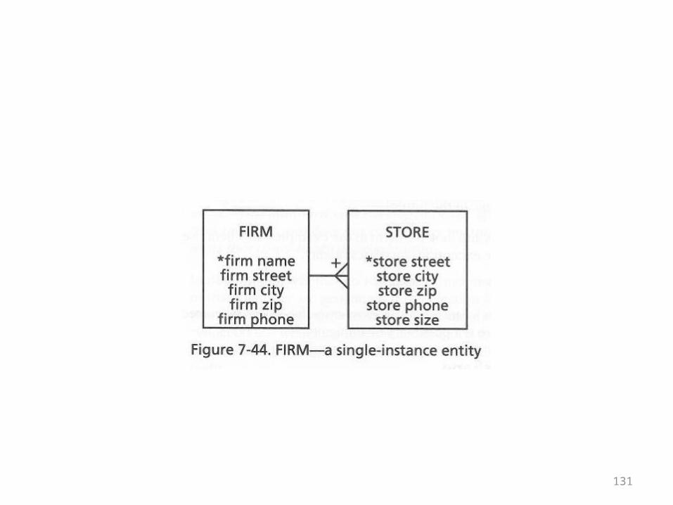
Single Instance Entities
• The moral of this story is that single instance entities—one row tables—are not a crime
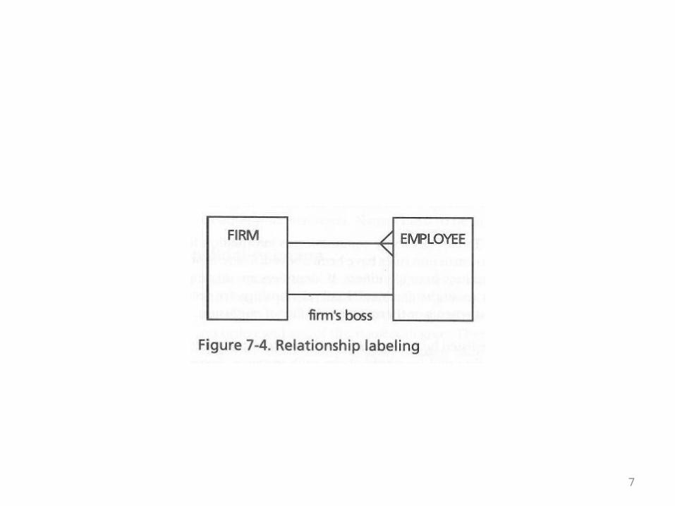
• In the example shown below there would be one firm listed
• Quite simply, this allows firm information to be stored
• It also makes it easy if two hold information about >1 firm if there happens to be a merger
131
132
Picking words
• The moral of the story here is to base the model on the vocabulary of the users
• It is important to root out inconsistencies in the users’ vocabulary if there are any
• However, cramming a different vocabulary down their throat won’t work
133
Synonyms
• Synonyms in data modeling are just like regular synonyms
• Different users or different groups of users use different words for the same thing
• Synonyms are not a technical problem• You may get users to agree on one word• You may also provide different views with
different vocabularies
134
Homonyms
• Homonyms in data modeling are just like regular homonyms
• Different users or different groups of users use the same words for different things
• Homonyms are not a technical problem, but they are a big practical problem
135
• They cause ambiguity and confusion and have to be tracked down
• Once identified, they are easy to fix• Qualify or expand the names of things so that
they are distinguished from each other
136
Exception hunting
• When working with clients (including yourself) ask these questions:
• Is it always like this?• Would there be any situations where this could be
an m:m relationship?• Have there ever been any exceptions?• Are things likely to change in the future?• A good data model should be able to handle
exceptional cases
137
Relationship labeling
• The book recommends avoiding relationship labels because they tend to clutter up an ER diagram
• It is true that most 1-m relationships should be clear
• However, if any relationship is unclear, it should be labeled
138
Keeping the data model in shape
• An illustrative example of this idea is very simple• As you work on a model, you might add an
entity• If you do so, do not forget to work out its
identifier and attributes before moving on to something else
• Making incomplete additions will quickly turn a model into a mess
139
Used entities
• Developing models is just like writing code• If you have an earlier model or someone else’s
model (that you trust) as a starting point, work from there
• There is no need to start from scratch every time
140
Meaningful identifiers
• This is the next major subsection• It mentions some things to avoid and some
things worth trying when picking identifiers, that is, when setting up primary key fields
• The phrase “meaningful identifier” means that you can read the key value and find out something useful about the record
• The complete opposite would be randomly generated identifiers
141
• In simple cases, meaningful identifiers might seem like an attractive option
• That would be memorable for users• The might be simple to administer
142
• However, they have disadvantages• If the reality you’re modeling becomes
complex, the identifiers are no longer easy to remember or administer
• If they are based on ranges of values, you may exhaust the available ranges
• If the underlying reality changes, previously meaningful identifiers lose their meaning
143
• Some large organizations have embedded codes into identifiers
• Vin’s contain certain identifiable parts• UPC codes also contain identifiable parts• If organizations choose to do this, it’s their
business• However, no independent organization has to
go down this path
144
• The general rule is that the disadvantages of meaningful identifiers outweigh the advantages
• Everything that could be coded into an identifier could be, and probably is recorded in an attribute field
• This means that you’ve returned to a situation where one field is dependent on another
• The possible result is inconsistency between the information coded in the identifier and the data recorded in the fields
• Whether random, entry order, or some other scheme, non-meaningful identifiers are preferable
145
The seven habits of highly effective data modelers
• This sounds like a bunch of management bullshit, but if you have to do modeling for clients, these are worthwhile hints:
• 1. Immerse• As a computer person, when modeling for
someone else, you have to learn their problem domain and terminology before you can make a good model.
146
• 2. Challenge• This means challenge the assumptions and
find the exceptions• 3. Generalize• This means, when possible, to merge entities
together so the model doesn’t proliferate
147
• 4. Test• Have structured walk-throughs at a detailed level,
checking entities, attributes, and especially, relationships
• 5. Limit• This means let the project drive the modeling; don’t
do modeling for the sake of modeling. The model is supposed to lead to practical results. If necessary apply the 80-20 rule in order to control the process.
148
• 6. Integrate• This means that modeling doesn’t happen in a
vacuum. If an organization has existing systems, fit the new model into the existing one.
• 7. Complete• Whatever limits you’ve set for yourself, complete
the model within those limits. Few things are more worthless than a model that hasn’t been finished.
149
Reference: Basic Structures
• The next set of overheads will be given without textual commentary
• This is essentially a repetition or review of the concepts that have been raised in chapters 3 through 7 in this set of overheads and the previous one
• This review will be followed by a short section relating object-oriented and relational design
150
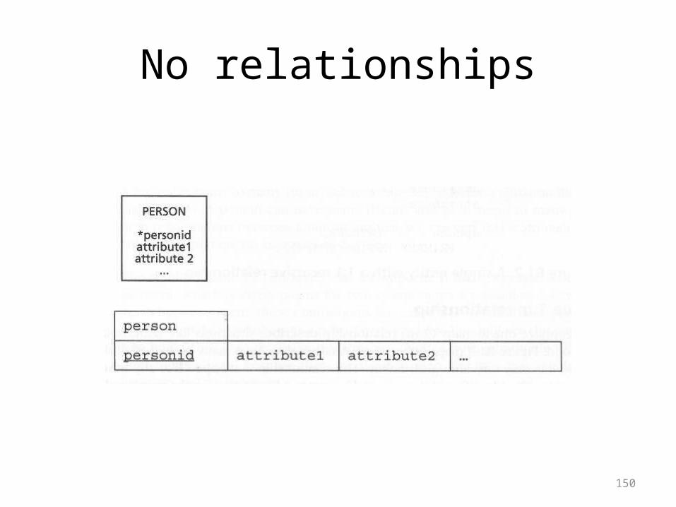
No relationships
151
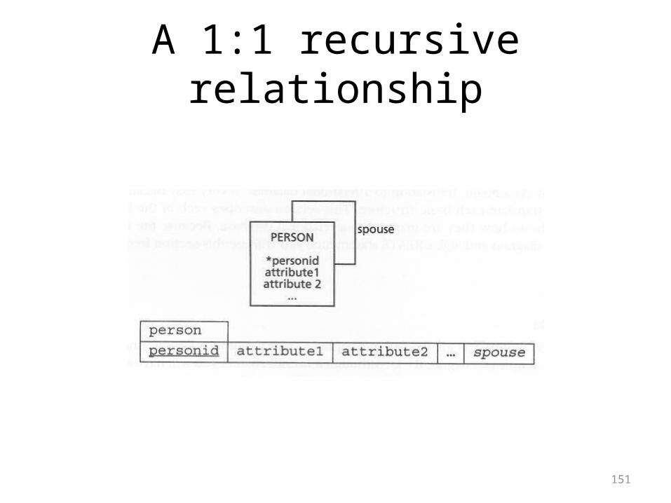
A 1:1 recursive relationship
152
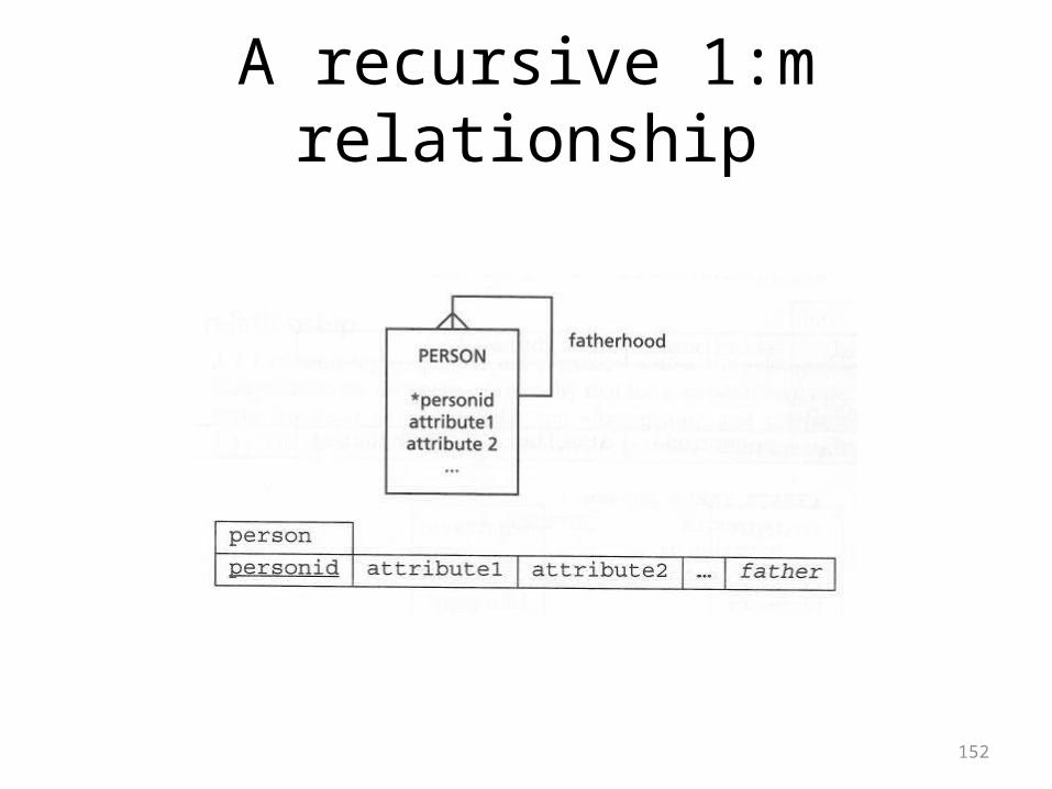
A recursive 1:m relationship
153
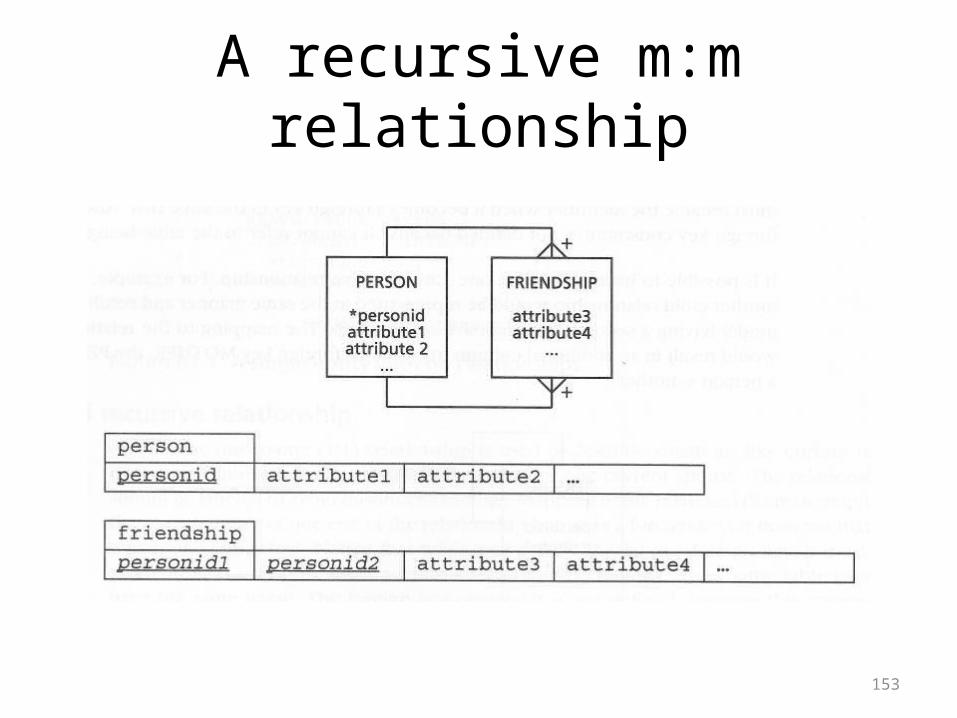
A recursive m:m relationship
154
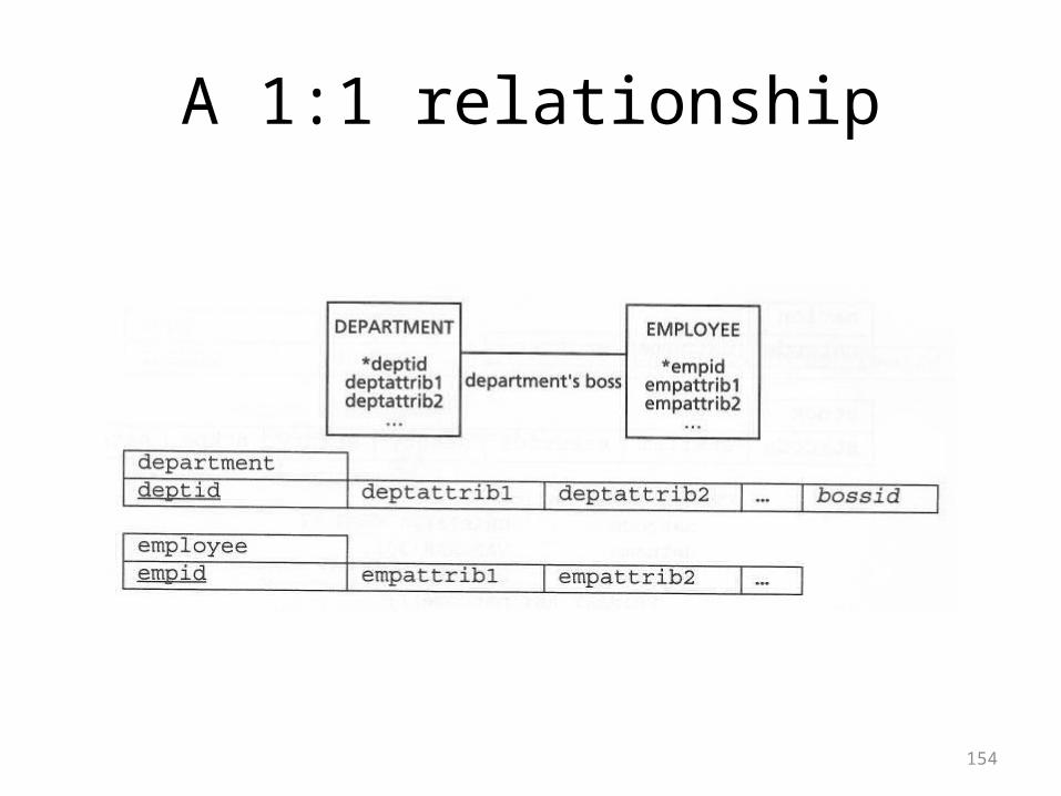
A 1:1 relationship
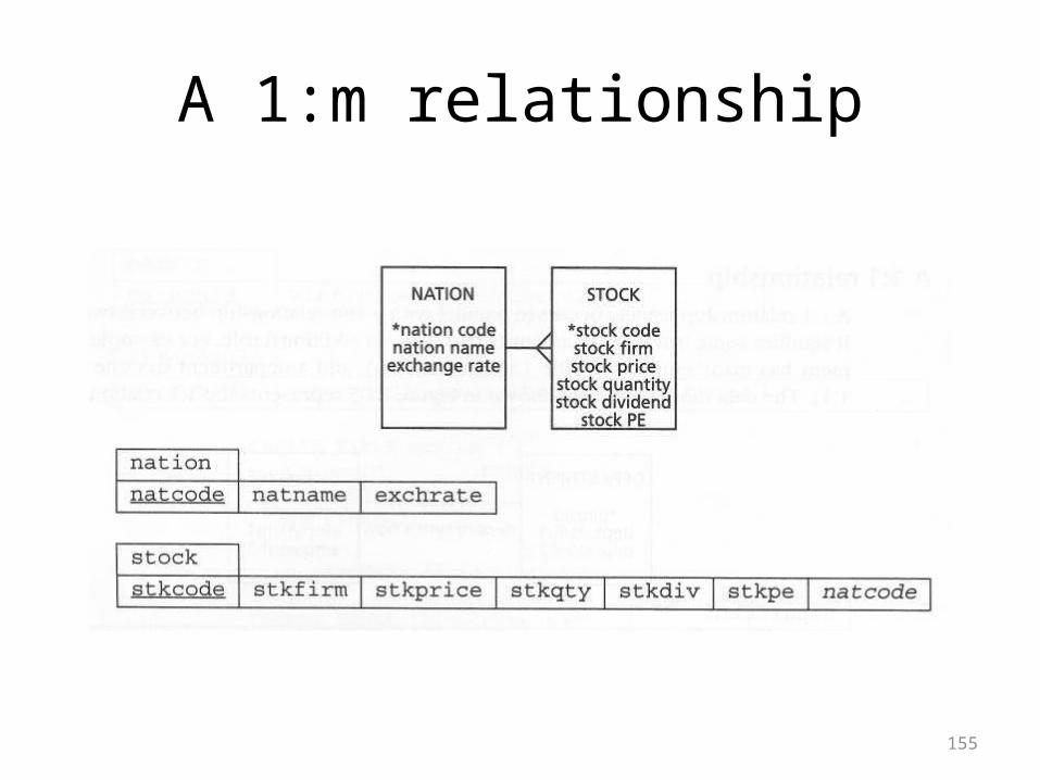
155
A 1:m relationship
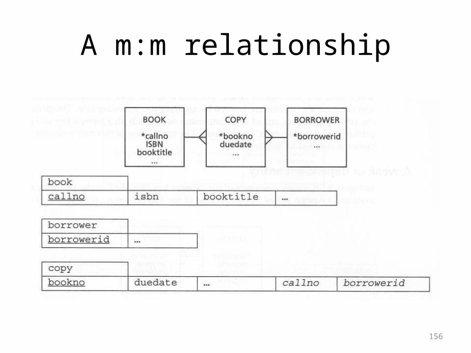
156
A m:m relationship
157
A weak or dependent entity
158
An associative entity
159
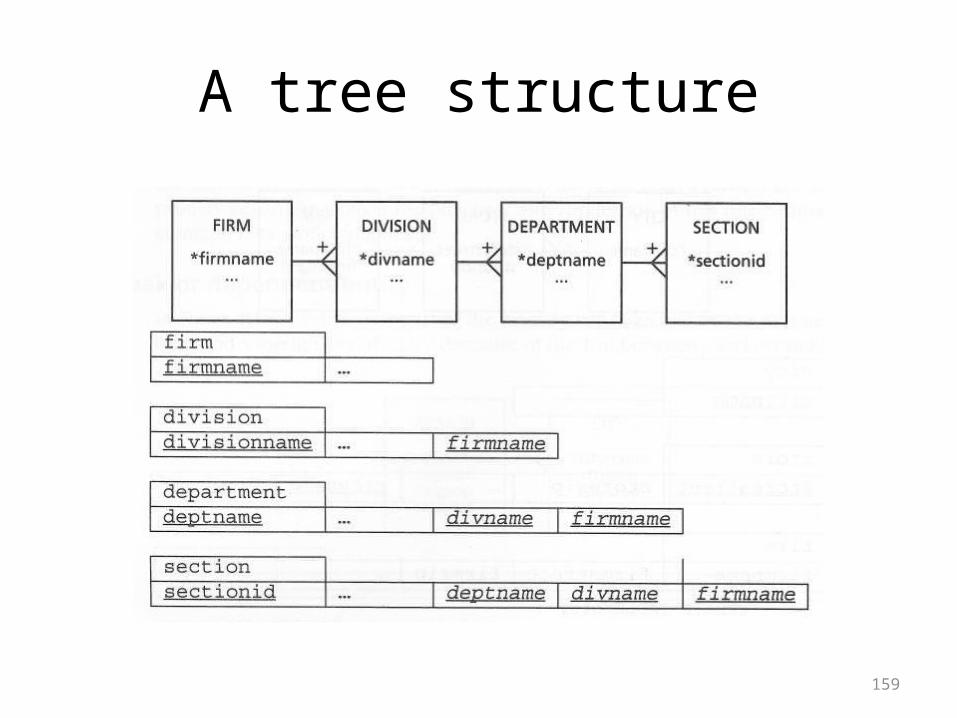
A tree structure
160
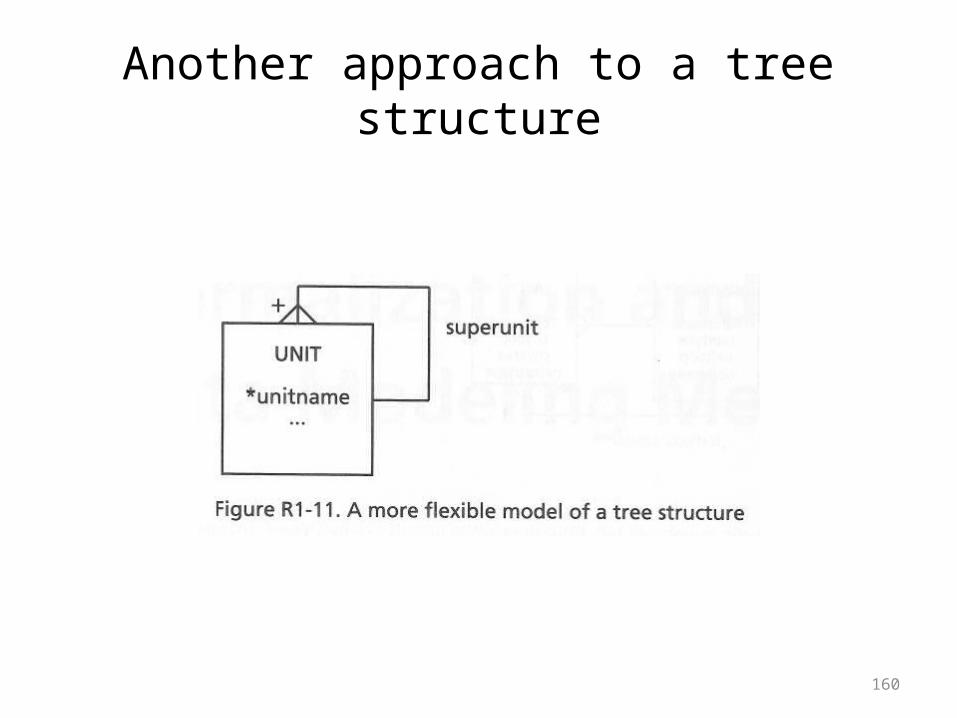
Another approach to a tree structure
161
Exercises
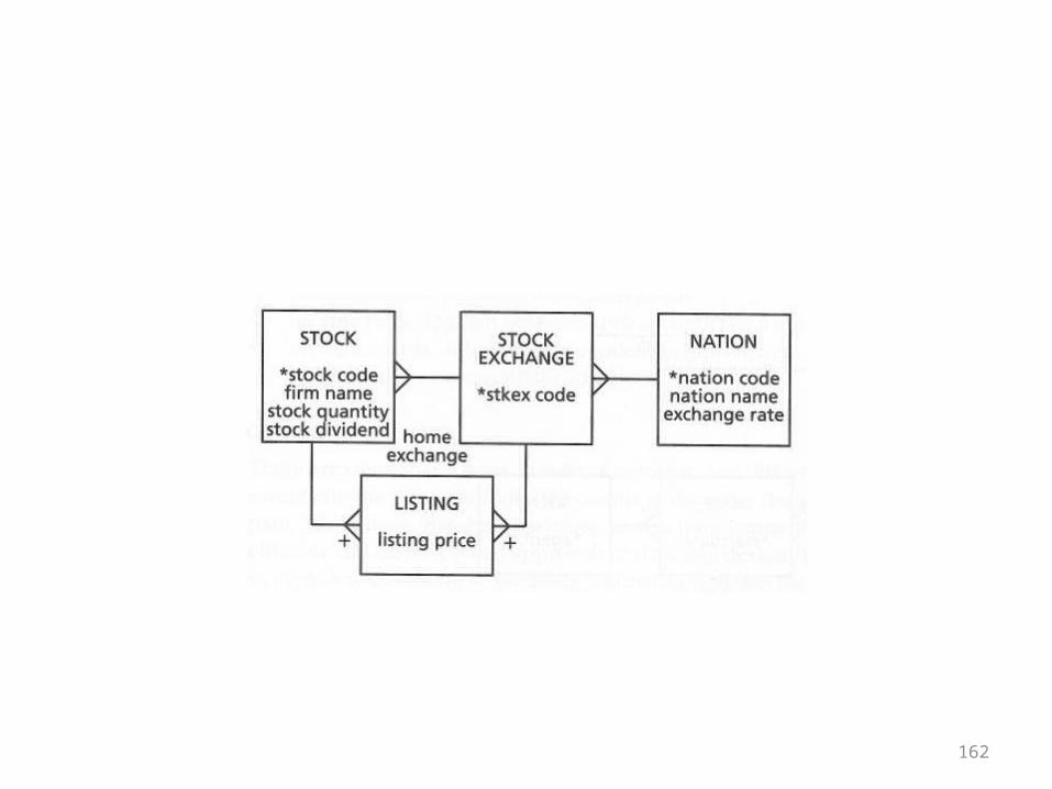
• The basic structures chapter ends with exercises where the directions are to write the SQL CREATE statements for the designs shown
• The designs came up in the chapters• They are repeated here just for reference• You should recognize them and know what
kind of structures they represent
162
163

164
165
166

167
• Ignore the remainder of the overheads• Material has been taken from another book
and included here• However, it will not be covered• It is simply kept here for future reference
168
Developing Software with UML: Object-Oriented Analysis and Design in Practice
• Bernd Oestereich• Chapter 2, Object-Orientation for Beginners• Section 2.13, Persistence• Synopsis– Persistence is the storing of objects on a non-
volatile medium– There is no one-to-one mapping to relational
databases
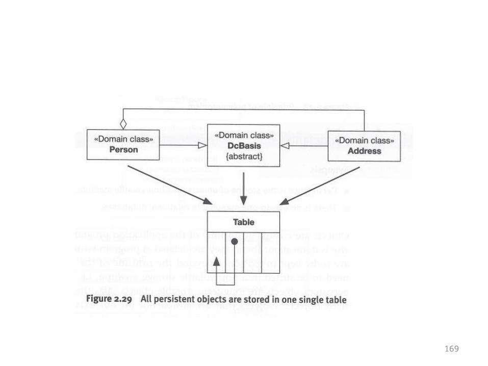
169
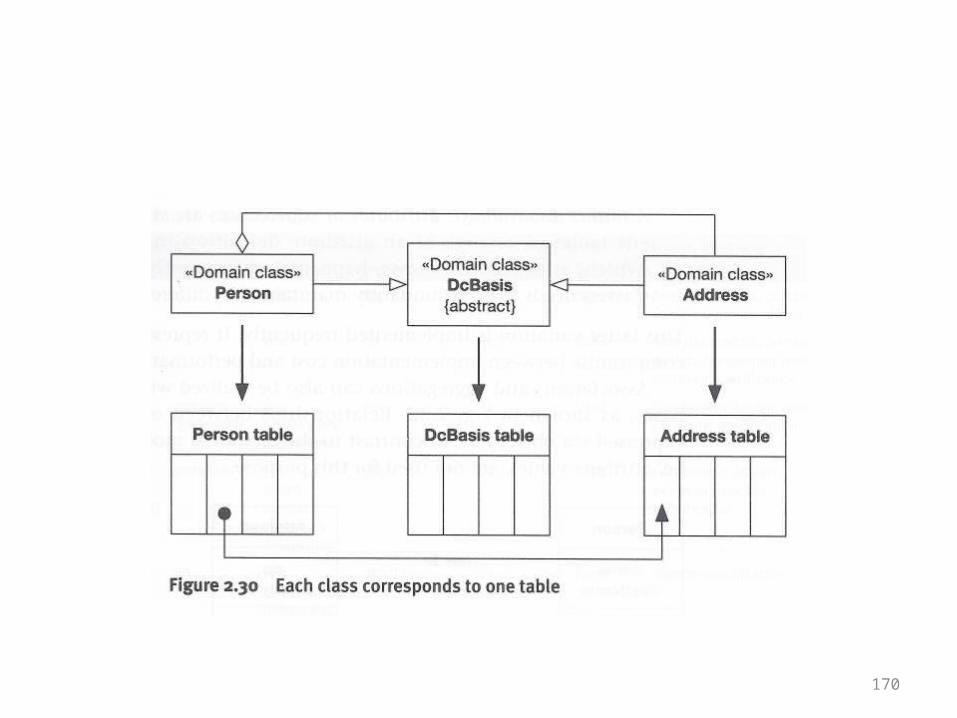
170
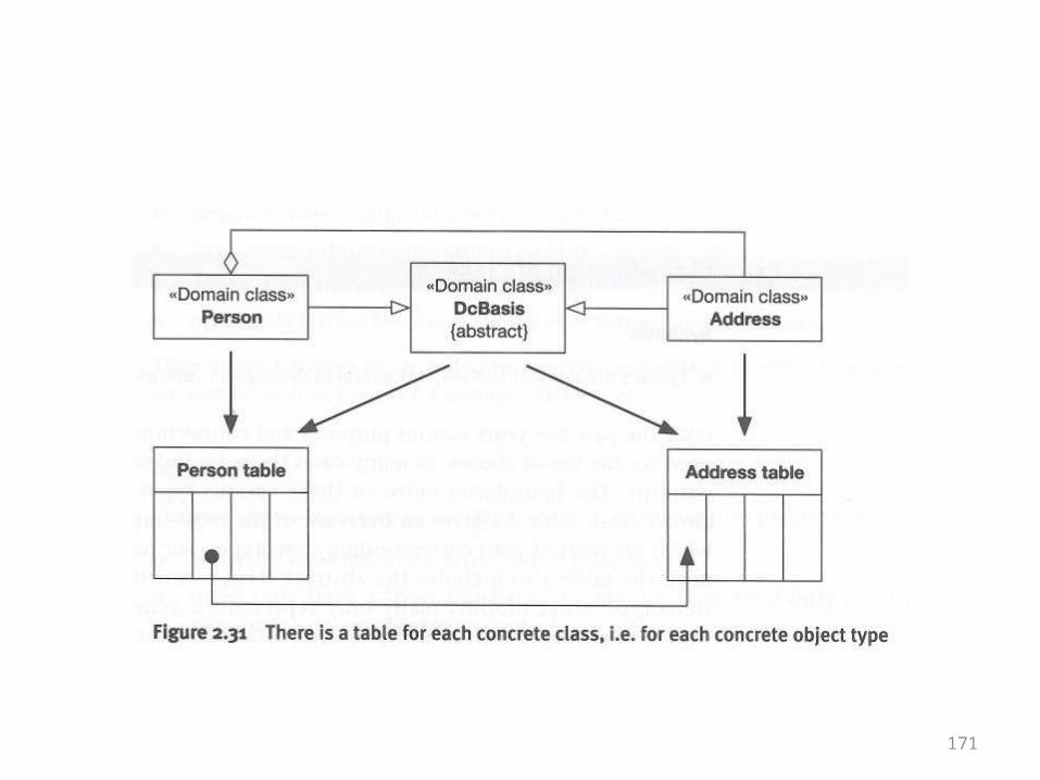
171
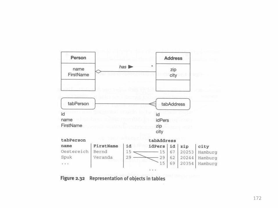
172

173
The End
Recommended