Head Offie
S P E C I F I C A T I O N S
FOR REFERENCE
4-2-2 Kamitakada, Nakano-ku, Tokyo, Japan 164-0002Tel 03-32233-1111 Fax 03-5380-7171
Diesel Engine-DrivenAC Generator
M O D E L : D C A - 2 5 E S I
Co.,Ltd.
1
2
1. A P P L I C A T I O N
1. 1 This specfication covers the water-colled, diesel engine-driven ACgenerator model DCA-25ESI (hereafter referred to as generating set).
1.2 This generating set shall be designed, manufactured and tested in accordance with the latest standards of of JIS, JEC and JEM. JIS: Japanese Industrial Standard JEC: Standard of the Japanese Electrtechnical Committe JEM: The Standard of the Japan Electrical Manufacture’s Associationother matters which are not specifically mentioned in the above standards shall be subject to Denyo Co.,Ltd.’s production regulations.
2. GENERAL
2.1 Materials and WorkmanshipThe materials used in the manufacture ofthis equipment shall be of thehigh quality, an shall be free from defects and imperfections.All materials and apparatus not manufactured by Denyo Co., Ltd. shall bethe products of wel;-known manufacturers. The workmanship shall be of thehigh grade and in accordance with the most efficient, up-to-dateprocedures.
2. 2 Change Minor changes after the final design may be made by Denyo Co., Ltd.without prior notice to the purchaser. In case of major changes oradditional equipment which may result in an increase or decrease ofequipment’s cost, such modifications shall be made in writing and agreed toby both parties prior to production and shall constitute an amendmentto these specifications.
2. 3 Tests and InspectionsRout tests and ispections shall be final in our factory.if any tests and ispections beyond the scope of Denyo’sstandardcommercial procedures are required by the purchser, charges for suchinspections or testsshall be added to our estimate. Conditions of any suchtests and inspections shall be mutually agreed upon between both parties.
3
3 . S T R U C T U R E
The generating set prossesses a solid structure, and is comprised of a water-cooleddiesel engine and a generator, which are directly coupled on a common base.A coupling housing is employed to connect the generator to the engine.Firm couplingof the engine and generator is ensured by tight connection ofthe housing exterior. The rotating section of the generator is directly coupledto the flywheel of the engine with a flexible coupling plates made of laminatedthin steel. The generator is of single bearing construction.The standard generator is of the brushless thpe.Aheavy gauge steel bonnet and side door completely cover the engine,generator and accessories, protecting the unit from effects of weathe orpossible handling damages at the construction site. A lifting hook is attached to the common base, and it extends to the balance point throug the bonnet top.
4. S P E C I F I C A T I O N S A N D P E R F O M A N C E
4.1 Ambient Conditions
This generating set should meet the following conditions:
(1) Ambient temperature :-5 ْ C or higher, 40 ْ C or lower (2) Altitude : up to 500m above sea level (3) Relative humidity : 85% or lower (4) Place of installation : indor and outdoor
-Note- Generator rated output is in accordance with JIS standard ambient conditions JIS standard ambient conditions (A) Ambient temperature : 25 ْC (B) Atmospheric pressure : 100 kP (C) Relatice humidity : 31%
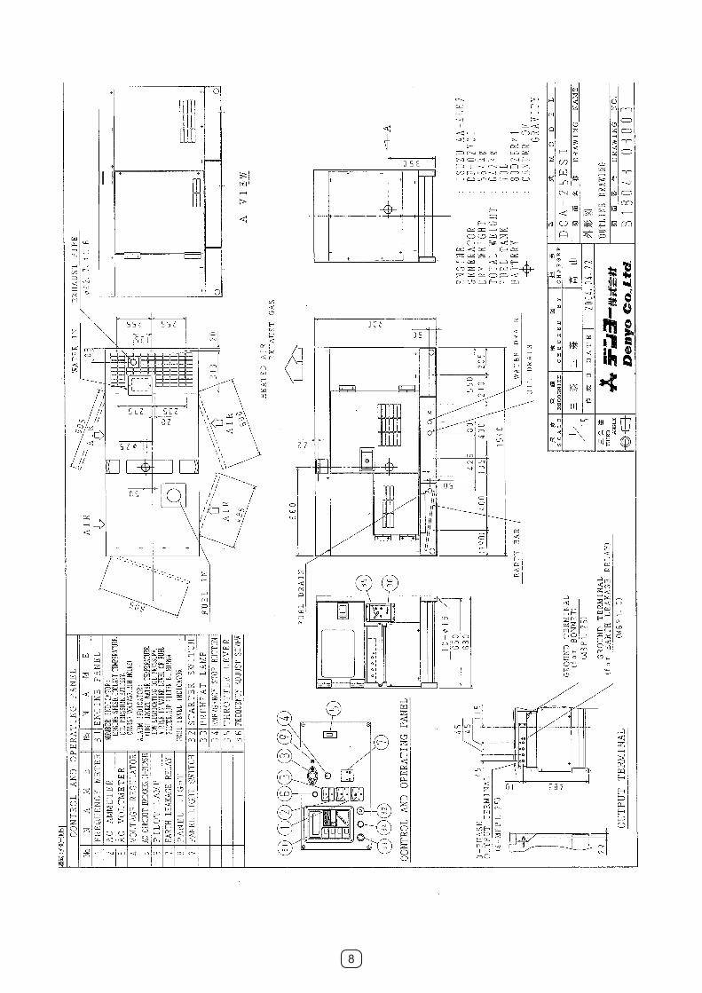
4.2 Dimensions and Weight
Lenth : 1550 mm Witdh : 650 mm Height : 900 mm Dry Weight : 564 kg
4
4.3 AC Generator
-NOTE- Continuous Duty Rating: The generating set is designed for continuous operation under normal load condition with an overload capacity (105% of rating capacity ) up to the standby rating for intermittent periods. Continuous duty rating is in accordance with JIS standard ambient conditions.
4.4 Engine
-NOTE- “Rated Output” is in accordance with JIS standard ambient conditions.
Generator ModelGenerator Type
ExcitationContiuous Rating
VoltageCurrent
FrequencyNo. of Poles
Winding ConnectionSpeed
Power FactorRatingPhase
Insulation System
Maker and ModelType
Rated OutputNo. cylinders
Bore X StrokePiston Displacement
Direction of RotationGovernor
Cooling SystemLubricating System
Starting MotorCharging Generator
BatteryFuel
Lubricating Oil
: ISUZU MOTORS, LTD AA-4LE2: 4 cycle, water-cooled, Diesel Engine,: swirl chamber type: 23.5 kW, 1800 min: 4: 85mm X 96mm: 2.179L: Clockwise (When viewed from the fan side): Mechanical all speed governor: Water cooling by radiator with fan: Gear pump: Electric Start (12 V - 2.0 kW): 12V - 20A: 80D26R (12V - 70Ah): Diesel fuel (ASTM No.2 or equivalent): API service class, CC class or higher
: DF-0220K: Rotating-field, protection type synchronous generator: Brushless type (with AVR): 20 kVA: 220 V: 52.4 A: 60 Hz: 4: Star: 1800 min-1
: 0.8 (lagging): 3 (4 wires): Class F: Self-ventilation
5
4.5 Capacity
Cooling watercapacity : 6.1 L Lube oil capacity : 8.5 L Fuel tank capacity : 70 L
5. PERFORMANCE
5.1 AC Voltage Regulation
The AC voltage regulation from no load to full rated load under a rated power factor shall not exceed 1.5% of the rated voltage.
5.2 Speed Regulation
The speed regulation from no lad to rated load under a rated powerfactor shall be within 5% of rated speed.
5.3 Sound Level
The average wound level shall not exceed 65 dB(A) at 7 meters from the machine.
5.4 Limits of Temperature
Limits of temperature rise of the generator shall be in accordance with relevant Japanese standards, based on ambient temperature not exceeding 40 ْC, and shall not exceed the following:
Armature windings 85ْ C (Insulation class F) Field windings 85ْ C (Insulation class F) Bearing 40ْ C
-NOTE- Method of measuring temperatures rise is thermometer method.
5.5 Dielectric Strength Test
The strength of the windings of the generator and control box shall meet the specifications of the high voltage test according to Japanese standards:
Armature windings - Grounding AC 1880v (one minute) Field windings - Grounding AC 1500v (one minute) Electrical parts - Grounding AC 1500v (one minute)
-NOTE- The dielectric strength test of semi conductive parts such as diode will be carried out without disconnecting the terminals.

6
6. INSTRUMENTATION ON THE CONTROL PANEL
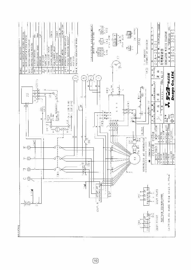
6.1 for AC Power
Frequency Meter AC Ammeter AC Voltmeter Voltage Regulator AC Circuit Breaker (for 3-Phase Output) Pilot Lamp Earth Leakage Relayy Panel Light Panel Light Switch Over Current Relay (in the control box) Voltage change Board (in the control box)
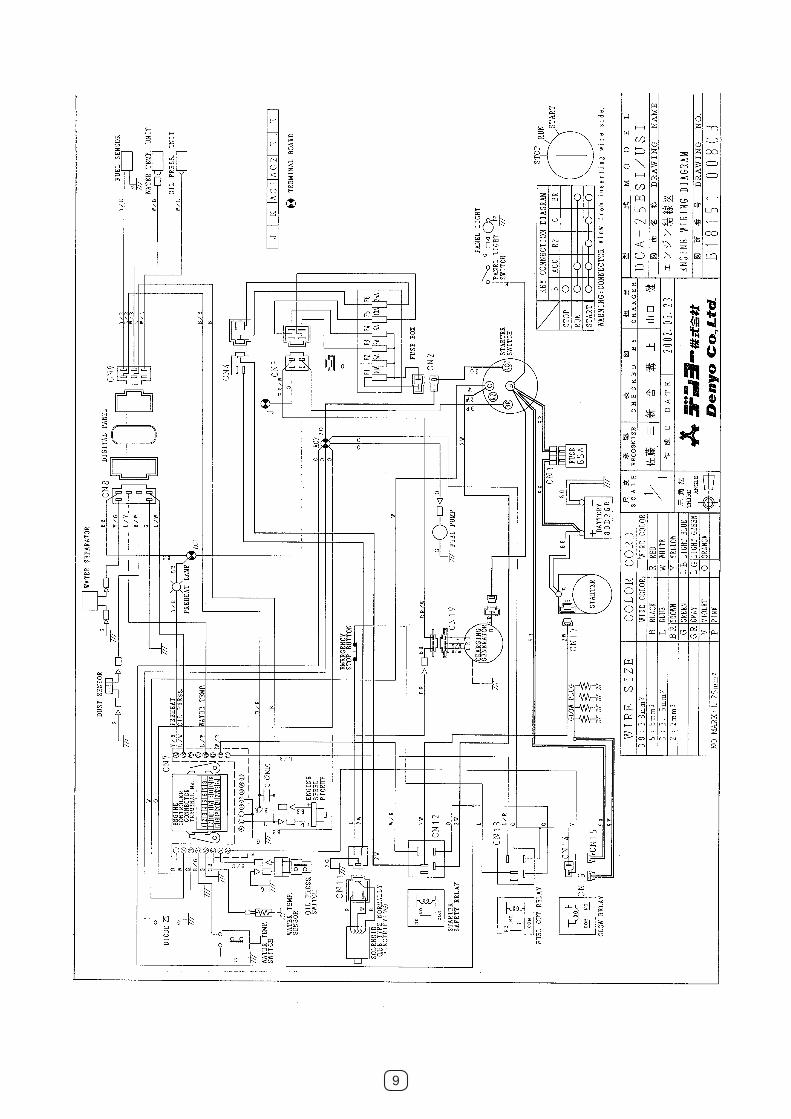
6.2 for Engine
Engine indicator unit Number indicator engine speed / engine oil pressure run hours / battery charging voltage engine coolant temperature Alarm indicator low lubricating oil pressure high jacket water temperature air element blinding a rise in water level of fuel filter Fuel level indicator Starter Switch Preheat Lamp Emergency Stop Button Throttle Lever Frequency adjust screw
6.3 Output Terminals
3-Phase Output Terminal Ground Terminal (for Earth Leakage Relay) Ground Terminal (for Bonnet)
1 pc.1 pc.1 pc.1 pc.1 pc.1 pc.1 pc.1 pc.1 pc.1 pc.1 pc.
1 pc.1 pc.1 pc.1 pc.1 pc.
1 set1 pc.1 pc.
1 set
7
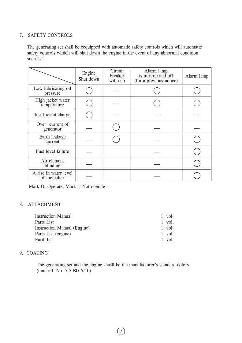
7. SAFETY CONTROLS
The generating set shall be eequipped with automatic safety controls which will automatic safety controls whiich will shut down the engine in the event of any abnormal condition such as:
8. ATTACHMENT
Instruction Manual 1 vol. Parts List 1 vol. Instruction Manual (Engine) 1 vol. Parts List (engine) 1 vol. Earth bar 1 vol.
9. COATING
The generating set and the engine shasll be the manufacturer’s standard colors (munsell No. 7.5 BG 5/10)
Mark O; Operate, Mark -: Not operate
EngineShut down
Circuitbreakerwill trip
Alarm lampis turn on and off
(for a previous notice)Alarm lamp
Low lubricating oilpressure
High jacket watertemperature
Insufficient charge
Over current ofgenerator
Earth leakagecurrent
Fuel level failure
Air elementblinding
A rise in water levelof fuel filter
8
9
10
Recommended