I
3ADW000177R0200_DCS500B_QuickGuide_edisf_b
DCS Thyristor Power ConvertersDCS Thyristor-Stromrichter
Convertitore di potenza a tiristori DCSConvertidor de potencia por tiristores DCS
Variateurs standards DCSТиристорные приводы постоянного тока DCS
DCS 500BQUICK GUIDE
КРАТКОЕ РУКОВОДСТВО
I
3ADW000177R0222_DCS500B_QuickGuide_ru_b
DCS 500B Краткое руководство
русск. яз.
СОДЕРЖАНИЕ1 Описание изделия ..................................... 32 Замечания, краткая инструкция на CD и
обзор документации ................................. 53 Замечания по ЭМС .................................... 84 Стандартные функции клемм
управления .............................................. 105 Пример подключения .............................. 116 Инструкция по технике безопасности и
эксплуатации ........................................... 137 Быстрый ввод в эксплуатацию .............. 148 Сообщения о состоянии .......................... 179 Размеры, разметка для сверления
отверстий и вес ....................................... 8310 Ошибки и предупреждения ..................... 8511 Перечень параметров ............................. 9412 Декларация о соответствии ................... 96
Декларация об использовании................ 97
deutsch
INHALT1 Produktbeschreibung ................................192 Hinweise, Kurzanweisung CD und
Dokumentationsübersicht ..........................213 EMV-Hinweise ..........................................244 Standard-Funktionsbelegung der
Klemmen ..................................................265 Anschlussschaltbild ..................................276 Sicherheits- und Anwendungshinweise ......297 Kurzinbetriebnahme ..................................308 Statusmeldungen ......................................339 Abmessungen, Bohrbild und Gewichte ......8310 Fehler und Alarme .....................................8511 Parameterliste ...........................................9412 Konformitätserklärungen ...........................96
Herstellererklärung ....................................97
italiano
INDICE1 Descrizione prodotto ................................. 352 Note, brevi istruzioni CD e documen-
tazione - Informazioni generali .................. 373 Note sulla compatibilità elettromagnetica ..404 Assegnazioni funzioni standard
per i morsetti ............................................. 425 Schema di collegamento ........................... 436 Istruzioni per la sicurezza ......................... 457 Istruzioni per la messa in servizio ............. 468 Messaggi di stato ..................................... 499 Dimensioni, schemi di foratura e pesi ....... 8310 Errori e allarmi ........................................... 8511 Lista dei parametri .................................... 9412 Dichiarazione di conformità ....................... 96
Dichiarazione di incorporazione ................. 97
español
CONTENIDO1 Descripción del producto .......................... 512 Instrucciones resumidas en CD, notas y
publicaciones adicionales ........................ 533 Notas acerca de EMC .............................. 564 Asignaciones de funciones estándar para los
terminales ................................................ 585 Diagrama de conexiones .......................... 596 Instrucciones de seguridad ...................... 617 Arranque rápido ........................................ 628 Mensajes de estado ................................. 659 Dimensiones, patrones de taladrado y pesos . 8310 Errores y alarmas .................................... 8511 Lista de parámetros ................................. 9412 Declaración de conformidad ..................... 96
Declaración de homologación ................... 97
français
SOMMAIRE1 Description des produits ........................... 672 CD des procédures abrégées,
informations et autres documents ............ 693 Règles de CEM ........................................ 724 Fonctions standards sur les bornes ......... 745 Schéma de câblage ................................. 756 Consignes de sécurité .............................. 777 Mémento de mise en route ....................... 788 Messages d’état ...................................... 819 Dimensions, calibres de perçage et
masses .................................................... 8310 Défauts et alarmes ................................... 8511 Liste de paramétres ................................. 9412 Déclaration de conformité ........................ 96
Déclaration d’incorporation ....................... 97
english
CONTENTS1 Product description ..................................... 32 Notes, brief instructions CD and
documents overview ................................... 53 Notes on EMC ............................................ 84 Standard function assignments for the
terminals ................................................... 105 Connection example ................................. 116 Safety and operating instructions .............. 137 Short start-up ............................................ 148 Status messages ...................................... 179 Dimensions, drilling patterns and weights .. 8310 Errors and alarms ..................................... 8511 List of parameters ..................................... 9412 Declaration of conformity .......................... 96
Declaration of Incorporation ...................... 97
I 3
engl
ish
R
NRTL /C
I 3
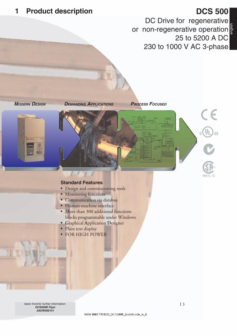
1 Product description
taken from/for further information:DCS500B Flyer3ADW000151
DCS 500DC Drive for regenerative
or non-regenerative operation25 to 5200 A DC
230 to 1000 V AC 3-phase
MODERN DESIGN DEMANDING APPLICATIONS PROCESS FOCUSED
Standard Features• Design and commissioning tools• Monitoring functions• Communication via databus• Human-machine interface• More than 300 additional functions
blocks programmable under Windows• Graphical Application Designer• Plain text display• FOR HIGH POWER
I 4 taken from/for further information:DCS500B Flyer3ADW000151
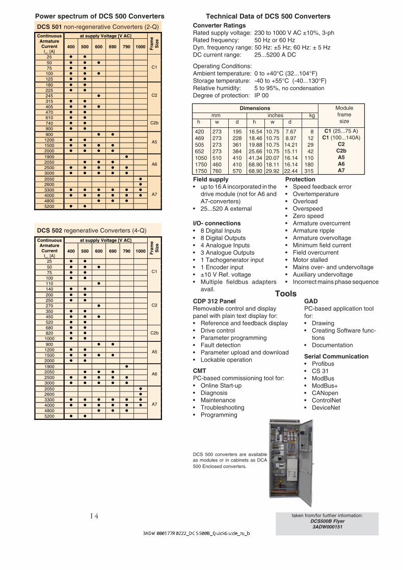
Power spectrum of DCS 500 ConvertersConverter RatingsRated supply voltage: 230 to 1000 V AC ±10%, 3-phRated frequency: 50 Hz or 60 HzDyn. frequency range: 50 Hz: ±5 Hz; 60 Hz: ± 5 HzDC current range: 25...5200 A DC
Operating Conditions:Ambient temperature: 0 to +40°C (32...104°F)Storage temperature: -40 to +55°C (-40...130°F)Relative humidity: 5 to 95%, no condensationDegree of protection: IP 00
Field supply• up to 16 A incorporated in the
drive module (not for A6 andA7-converters)
• 25...520 A external
I/O- connections• 8 Digital Inputs• 8 Digital Outputs• 4 Analogue Inputs• 3 Analogue Outputs• 1 Tachogenerator input• 1 Encoder input• ±10 V Ref. voltage• Multiple fieldbus adapters
avail.
Protection• Speed feedback error• Overtemperature• Overload• Overspeed• Zero speed• Armature overcurrent• Armature ripple• Armature overvoltage• Minimum field current• Field overcurrent• Motor stalled• Mains over- and undervoltage• Auxiliary undervoltage• Incorrect mains phase sequence
CDP 312 PanelRemovable control and displaypanel with plain text display for:• Reference and feedback display• Drive control• Parameter programming• Fault detection• Parameter upload and download• Lockable operation
Technical Data of DCS 500 Converters
CMTPC-based commissioning tool for:• Online Start-up• Diagnosis• Maintenance• Troubleshooting• Programming
DCS 502 regenerative Converters (4-Q)
DCS 501 non-regenerative Converters (2-Q)
GADPC-based application toolfor:• Drawing• Creating Software func-
tions• Documentation
Tools
DCS 500 converters are availableas modules or in cabinets as DCA500 Enclosed converters.
Serial Communication• Profibus• CS 31• ModBus• ModBus+• CANopen• ControlNet• DeviceNet
at supply Voltage [V AC] Continuous Armature Current I
DC [A]
400
500
600
690
790
1000 F
ram
e S
ize
25 50 75 100 125
C1
180 225 245 315 405 470
C2
610 740 900
C2b
900 1200 1500 2000
A5
1900 2050 2500 3000
A6
2050 2600 3300 4000 4800 5200
A7
at supply Voltage [V AC] Continuous Armature Current IDC
[A]
400
500
600
690
790
1000 F
ram
e S
ize
25 50 75 100 110 140
C1
200 250 270 350 450 520
C2
680 820
1000
C2b
900 1200 1500 2000
A5
1900 2050 2500 3000
A6
2050 2600 3300 4000 4800 5200
A7
Moduleframesize
C1 (25...75 A)C1 (100...140A)
C2C2bA5A6A7
Dimensionsmm inches kg
h w d h w d
420 273 195 16.54 10.75 7.67 8469 273 228 18.46 10.75 8.97 12505 273 361 19.88 10.75 14.21 29652 273 384 25.66 10.75 15.11 421050 510 410 41.34 20.07 16.14 1101750 460 410 68.90 18.11 16.14 1801750 760 570 68.90 29.92 22.44 315
I 5
engl
ish
2 Notes, brief instructions CD and documents overview
We are gratified that you have purchased anABB DC drive power converter, and thank youfor the confidence you have displayed in ourproducts.
To make sure that you continue to be satisfiedwith our product, we have put together thisbrochure for you. It is intended primarily toprovide you with a brief overview of the product'skey data, EMC notes, typical applications, start-up and trouble-shooting.
If you require further information on the productconcerned, then in addition to this brief docu-mentation you are provided with a CD-ROM(this CD-ROM is an integral part of this docu-mentation package) in the five main languagesEnglish, German, Italian, Spanish and French,featuring the following contents:
Documentation
Documentation on our product series:• DCS400• DCS500• DCS600
Our documentation is basically structured onthe following system:
System descriptionas comprehensive information on the planningof the overall power converter system.
Technical dataas detailed information, with all important partic-ulars on the individual components, like moduledimensions, electronics boards, fans and ancil-lary components.
Operating instructionswith all the requisite information on starting upand maintaining the entire drive, in detailedform.
Software description plus application blocksrequired only for programming the drive, availa-ble only in English and not in printed form.
Service Manualfor maintenance and repair of the units.
Plus sundry information on applications (e.g.12-pulse) and technical accessories, etc.
System requirements for using theCD-ROM
• Operating system WINDOWS 98, NT, 2000,XP
• ACROBAT READER 4.0 sufficient (we rec-ommend 5.0 - included on the CD-ROM)
• INTERNET Explorer 5.0 or a later versionIf the CD ROM won’t start automatically pleasedouble-click on START.HTM
Further support
In addition, we offer further support, since it'sonly when you as the customer are satisfied withus and your decision that we can be satisfiedtoo.
InternetOn the ABB homepage under
www.abb.com/dc
you'll find abundant information provided on• DC products• service support• the latest updates• tools• downloads, etc.Please don't hesitate to visit us there.
Contacting usIf you require any further information, please talkto your nearest ABB Drives office or send anemail to:
Please give us your name, your company, ad-dress and phone number, and we will immedi-ately inform you of the contact person responsi-ble for you.
I 6
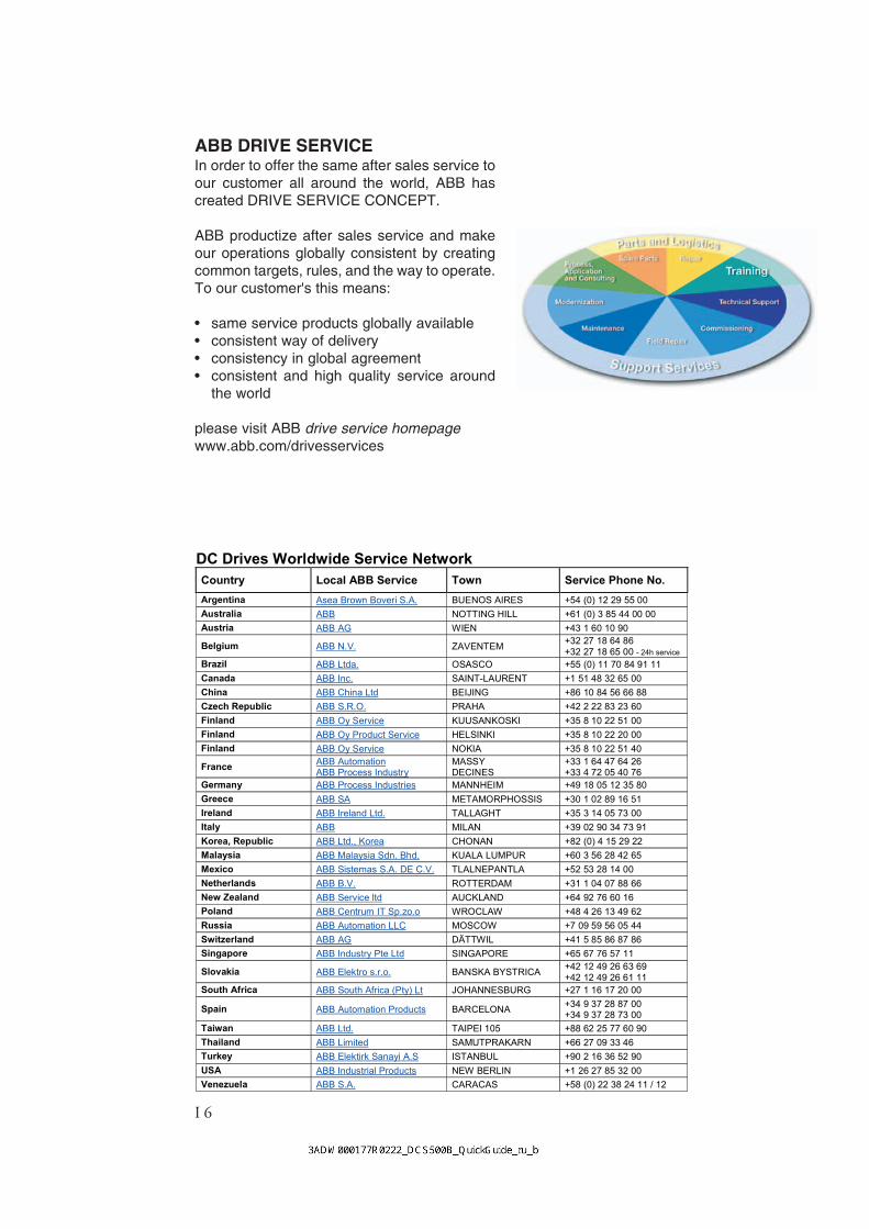
ABB DRIVE SERVICEIn order to offer the same after sales service toour customer all around the world, ABB hascreated DRIVE SERVICE CONCEPT.
ABB productize after sales service and makeour operations globally consistent by creatingcommon targets, rules, and the way to operate.To our customer's this means:
• same service products globally available• consistent way of delivery• consistency in global agreement• consistent and high quality service around
the world
please visit ABB drive service homepagewww.abb.com/drivesservices
DC Drives Worldwide Service Network Country Local ABB Service Town Service Phone No. Argentina Asea Brown Boveri S.A. BUENOS AIRES +54 (0) 12 29 55 00 Australia ABB NOTTING HILL +61 (0) 3 85 44 00 00 Austria ABB AG WIEN +43 1 60 10 90
Belgium ABB N.V. ZAVENTEM +32 27 18 64 86 +32 27 18 65 00 - 24h service
Brazil ABB Ltda. OSASCO +55 (0) 11 70 84 91 11 Canada ABB Inc. SAINT-LAURENT +1 51 48 32 65 00 China ABB China Ltd BEIJING +86 10 84 56 66 88 Czech Republic ABB S.R.O. PRAHA +42 2 22 83 23 60 Finland ABB Oy Service KUUSANKOSKI +35 8 10 22 51 00 Finland ABB Oy Product Service HELSINKI +35 8 10 22 20 00 Finland ABB Oy Service NOKIA +35 8 10 22 51 40
France ABB Automation ABB Process Industry
MASSY DECINES
+33 1 64 47 64 26 +33 4 72 05 40 76
Germany ABB Process Industries MANNHEIM +49 18 05 12 35 80 Greece ABB SA METAMORPHOSSIS +30 1 02 89 16 51 Ireland ABB Ireland Ltd. TALLAGHT +35 3 14 05 73 00 Italy ABB MILAN +39 02 90 34 73 91 Korea, Republic ABB Ltd., Korea CHONAN +82 (0) 4 15 29 22 Malaysia ABB Malaysia Sdn. Bhd. KUALA LUMPUR +60 3 56 28 42 65 Mexico ABB Sistemas S.A. DE C.V. TLALNEPANTLA +52 53 28 14 00 Netherlands ABB B.V. ROTTERDAM +31 1 04 07 88 66 New Zealand ABB Service ltd AUCKLAND +64 92 76 60 16 Poland ABB Centrum IT Sp.zo.o WROCLAW +48 4 26 13 49 62 Russia ABB Automation LLC MOSCOW +7 09 59 56 05 44 Switzerland ABB AG DÄTTWIL +41 5 85 86 87 86 Singapore ABB Industry Pte Ltd SINGAPORE +65 67 76 57 11
Slovakia ABB Elektro s.r.o. BANSKA BYSTRICA +42 12 49 26 63 69 +42 12 49 26 61 11
South Africa ABB South Africa (Pty) Lt JOHANNESBURG +27 1 16 17 20 00
Spain ABB Automation Products BARCELONA +34 9 37 28 87 00 +34 9 37 28 73 00
Taiwan ABB Ltd. TAIPEI 105 +88 62 25 77 60 90 Thailand ABB Limited SAMUTPRAKARN +66 27 09 33 46 Turkey ABB Elektirk Sanayi A.S ISTANBUL +90 2 16 36 52 90 USA ABB Industrial Products NEW BERLIN +1 26 27 85 32 00 Venezuela ABB S.A. CARACAS +58 (0) 22 38 24 11 / 12
I 7
engl
ish
DCS 500B documents
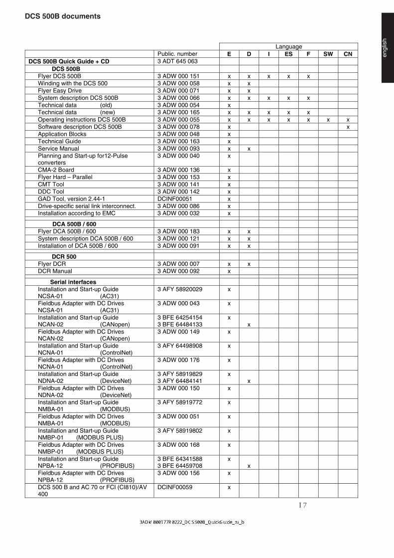
Language Public. number E D I ES F SW CN DCS 500B Quick Guide + CD 3 ADT 645 063 DCS 500B
Flyer DCS 500B 3 ADW 000 151 x x x x x Winding with the DCS 500 3 ADW 000 058 x x Flyer Easy Drive 3 ADW 000 071 x x System description DCS 500B 3 ADW 000 066 x x x x x Technical data (old) 3 ADW 000 054 x Technical data (new) 3 ADW 000 165 x x x x x Operating instructions DCS 500B 3 ADW 000 055 x x x x x x x Software description DCS 500B 3 ADW 000 078 x x Application Blocks 3 ADW 000 048 x Technical Guide 3 ADW 000 163 x Service Manual 3 ADW 000 093 x x Planning and Start-up for12-Pulse converters
3 ADW 000 040 x
CMA-2 Board 3 ADW 000 136 x Flyer Hard – Parallel 3 ADW 000 153 x CMT Tool 3 ADW 000 141 x DDC Tool 3 ADW 000 142 x GAD Tool, version 2.44-1 DCINF00051 x Drive-specific serial link interconnect. 3 ADW 000 086 x Installation according to EMC 3 ADW 000 032 x
DCA 500B / 600 Flyer DCA 500B / 600 3 ADW 000 183 x x System description DCA 500B / 600 3 ADW 000 121 x x Installation of DCA 500B / 600 3 ADW 000 091 x x
DCR 500 Flyer DCR 3 ADW 000 007 x x DCR Manual 3 ADW 000 092 x
Serial interfaces Installation and Start-up Guide NCSA-01 (AC31)
3 AFY 58920029 x
Fieldbus Adapter with DC Drives NCSA-01 (AC31)
3 ADW 000 043 x
Installation and Start-up Guide NCAN-02 (CANopen)
3 BFE 64254154 3 BFE 64484133
x x
Fieldbus Adapter with DC Drives NCAN-02 (CANopen)
3 ADW 000 149 x
Installation and Start-up Guide NCNA-01 (ControlNet)
3 AFY 64498908 x
Fieldbus Adapter with DC Drives NCNA-01 (ControlNet)
3 ADW 000 176 x
Installation and Start-up Guide NDNA-02 (DeviceNet)
3 AFY 58919829 3 AFY 64484141
x x
Fieldbus Adapter with DC Drives NDNA-02 (DeviceNet)
3 ADW 000 150 x
Installation and Start-up Guide NMBA-01 (MODBUS)
3 AFY 58919772 x
Fieldbus Adapter with DC Drives NMBA-01 (MODBUS)
3 ADW 000 051 x
Installation and Start-up Guide NMBP-01 (MODBUS PLUS)
3 AFY 58919802 x
Fieldbus Adapter with DC Drives NMBP-01 (MODBUS PLUS)
3 ADW 000 168 x
Installation and Start-up Guide NPBA-12 (PROFIBUS)
3 BFE 64341588 3 BFE 64459708
x x
Fieldbus Adapter with DC Drives NPBA-12 (PROFIBUS)
3 ADW 000 156 x
DCS 500 B and AC 70 or FCI (CI810)/AV 400
DCINF00059 x
I 8 for further information:Technical Guide
3ADW000163 - chapter 2.1
Classification
Not applicable
First environment (residential area with light industry) with restricted distribution
Not applied, since general distribution sales channel excluded
satisfied
satisfied
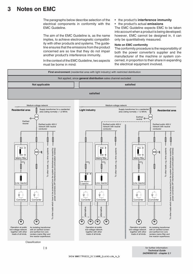
The paragraphs below describe selection of theelectrical components in conformity with theEMC Guideline.
The aim of the EMC Guideline is, as the nameimplies, to achieve electromagnetic compatibil-ity with other products and systems. The guide-line ensures that the emissions from the productconcerned are so low that they do not impairanother product's interference immunity.
In the context of the EMC Guideline, two aspectsmust be borne in mind:
• the product's interference immunity• the product's actual emissionsThe EMC Guideline expects EMC to be takeninto account when a product is being developed;however, EMC cannot be designed in, it canonly be quantitatively measured.
Note on EMC conformityThe conformity procedure is the responsibility ofboth the power converter's supplier and themanufacturer of the machine or system con-cerned, in proportion to their share in expandingthe electrical equipment involved.
3 Notes on EMC
MM
Mains filter
Converter
Line reactor
Supply transformer for a residential area (rating normally ≤ 1,2 MVA)
Earthed public 400-V network with neutral conductor
Medium-voltage network
Earthed neutral
To
oth
er
load
s, e
.g. d
rive
sys
tem
s
An isolating transformer with an earthed screen and earthed iron core renders mains filter and line reactor superfluous.
Operation at public low-voltage network
together with other loads of all kinds.
Residential area
To
oth
er
load
s w
hich
hav
e to
be
pro
tect
ed
from
the
syst
em d
istu
rban
ces
caus
ed
by
pow
er c
onv
ert
ers
(HF
inte
rfer
enc
e an
d co
mm
utat
ion
no
tche
s)
Converter
MMMM MM
alte
rnat
ive
alte
rnat
ive
Line reactor + Y-capacitor
Medium-voltage network
Supply transformer for a residential area (rating normally ≤ 1.2 MVA)
Earthed neutral
Earthed public 400-V network with neutral conductor
To
oth
er
load
s, e
.g. d
rive
sys
tem
s
Mains filter
Line reactor
Converter Converter
Mains filter
Line reactor
Converter Converter
An isolating transformer with an earthed screen and earthed iron core renders mains filter and line reactor superfluous.
Operation at public low-voltage network
together with other loads of all kinds.
To
oth
er
load
s, e
.g. d
rive
sys
tem
s
To
oth
er
load
s w
hich
hav
e to
be
pro
tect
ed
from
the
syst
em d
istu
rban
ces
caus
ed
by
pow
er c
onv
ert
ers
(HF
inte
rfer
enc
e an
d co
mm
utat
ion
no
tche
s)
Earthed public 400-V network with neutral conductor
Operation at public low-voltage network together with other loads of all kinds.
Light industry Residential area
I 9
engl
ish
for further information:Technical Guide
3ADW000163 - chapter 2.1
satisfied
satisfied
Second environment (industry) with restricted distribution
on customer's request satisfied
Not applicable
Classification
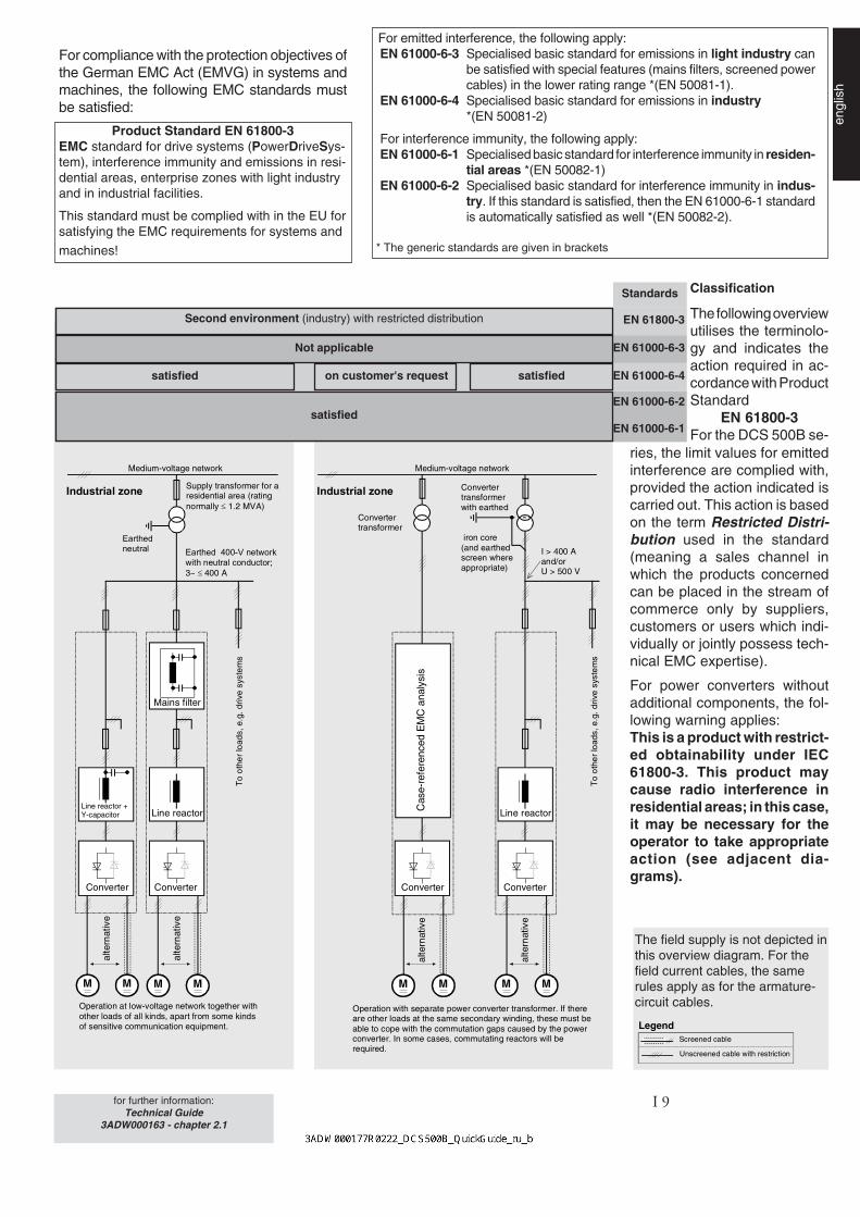
The following overviewutilises the terminolo-gy and indicates theaction required in ac-cordance with ProductStandard
EN 61800-3For the DCS 500B se-
For compliance with the protection objectives ofthe German EMC Act (EMVG) in systems andmachines, the following EMC standards mustbe satisfied:
Product Standard EN 61800-3EMC standard for drive systems (PowerDriveSys-tem), interference immunity and emissions in resi-dential areas, enterprise zones with light industryand in industrial facilities.
This standard must be complied with in the EU forsatisfying the EMC requirements for systems and
machines!
The field supply is not depicted inthis overview diagram. For thefield current cables, the samerules apply as for the armature-circuit cables.
ries, the limit values for emittedinterference are complied with,provided the action indicated iscarried out. This action is basedon the term Restricted Distri-bution used in the standard(meaning a sales channel inwhich the products concernedcan be placed in the stream ofcommerce only by suppliers,customers or users which indi-vidually or jointly possess tech-nical EMC expertise).
For power converters withoutadditional components, the fol-lowing warning applies:This is a product with restrict-ed obtainability under IEC61800-3. This product maycause radio interference inresidential areas; in this case,it may be necessary for theoperator to take appropriateaction (see adjacent dia-grams).
MMMM
Supply transformer for a residential area (rating normally ≤ 1.2 MVA)
Earthed 400-V network with neutral conductor; 3~ ≤ 400 A
Operation at low-voltage network together with other loads of all kinds, apart from some kinds of sensitive communication equipment.
To
oth
er
load
s, e
.g. d
rive
sys
tem
s
Line reactor + Y-capacitor Line reactor
Converter Converter
Mains filter
Earthed neutral
Medium-voltage network
Industrial zone
alte
rnat
ive
alte
rnat
ive
MMMM
Convertertransformer
Cas
e-re
fere
nced
EM
C a
naly
sis
alte
rnat
ive
Converter transformer with earthed
iron core (and earthed screen where appropriate)
alte
rnat
ive
I > 400 A and/or U > 500 V
Operation with separate power converter transformer. If there are other loads at the same secondary winding, these must be able to cope with the commutation gaps caused by the power converter. In some cases, commutating reactors will be required.
To
oth
er
load
s, e
.g. d
rive
sys
tem
s
Converter Converter
Line reactor
Medium-voltage network
Industrial zone
Legend
Unscreened cable with restriction
Screened cable
For emitted interference, the following apply:EN 61000-6-3 Specialised basic standard for emissions in light industry can
be satisfied with special features (mains filters, screened powercables) in the lower rating range *(EN 50081-1).
EN 61000-6-4 Specialised basic standard for emissions in industry*(EN 50081-2)
For interference immunity, the following apply:EN 61000-6-1 Specialised basic standard for interference immunity in residen-
tial areas *(EN 50082-1)EN 61000-6-2 Specialised basic standard for interference immunity in indus-
try. If this standard is satisfied, then the EN 61000-6-1 standardis automatically satisfied as well *(EN 50082-2).
* The generic standards are given in brackets
EN 61800-3
EN 61000-6-3
EN 61000-6-4
EN 61000-6-2
EN 61000-6-1
satisfied
satisfied
Second environment (industry) with restricted distribution
on customer's request satisfied
Not applicable
Standards
I 10 taken from/for further information:Technical data
3ADW000165 - chapter 3
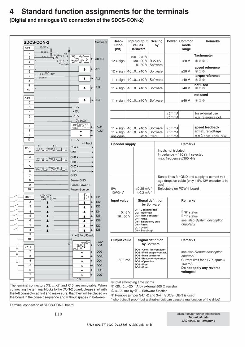
4 Standard function assignments for the terminals
Terminal connection of SDCS-CON-2 board
(Digital and analogue I/O connection of the SDCS-CON-2)
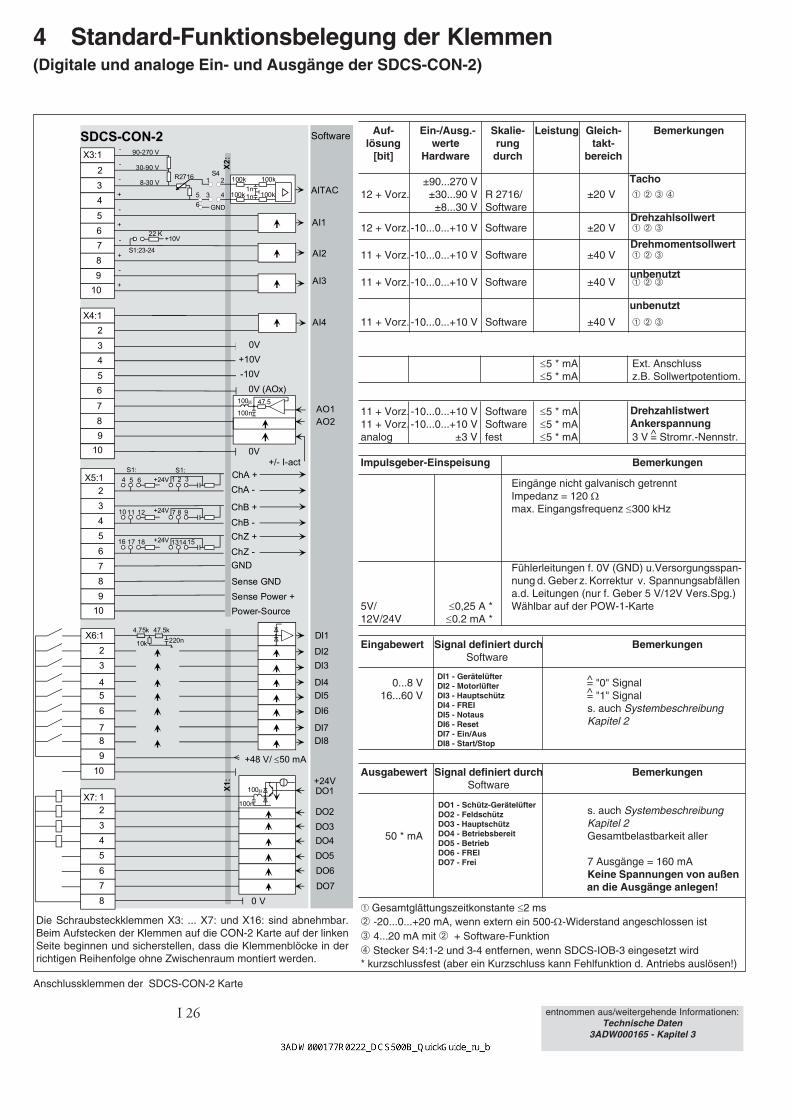
The terminal connectors X3: ... X7: and X16: are removable. Whenconnecting the terminal blocks to the CON-2 board, please start withthe left connector at first and make sure, that they will be placed onthe board in the correct sequence and without spaces in between.
X2:
X1:
AITAC
90-270 V
30-90 V
8-30 V
+24V
AI4
ChA +ChA -
ChB +ChB -ChZ +ChZ -GND
0 V
R2716
+10V
S1:23-24
100µ
+48 V/ ≤50 mA
100k1n1n
100n
100k
100k 100k
Power-Source
Sense GNDSense Power +
0V
AI2
AI3
AI1-
+
-
+
-
+
-
-
-
+
AO1AO2
+/- I-act
47.5100µ
100n
0V (AOx)
+10V0V
-10V
DI1
DI2DI3
DI4DI5DI6
DI7DI8
47.5k220n10k
4.75k
DO4DO5
DO7
DO1
DO2DO3
DO6
22 K
345
87
67
9
X6:1 2 3
4 5 6
7 8
10
4 5
7
1 2 3
6
4
23
65
910
89
10
2
45
7
23
6
89
10
8
X3:1
X4:1
X5:1
X7:
SDCS-CON-2 Software
+24V 7 8 910 11 12
+24V 13141516 17 18
+24V4 5 6S1:
1 2 3S1:
GND
1 2
3 456
S4
Reso- Input/output Scaling Power Common Remarkslution values by mode[bit] Hardware range
±90...270 V12 + sign ±30...90 V R 2716/ ±20 V ➀ ➁ ➂ ➃
±8...30 V Software
12 + sign -10...0...+10 V Software ±20 V ➀ ➁ ➂
11 + sign -10...0...+10 V Software ±40 V ➀ ➁ ➂
11 + sign -10...0...+10 V Software ±40 V ➀ ➁ ➂
11 + sign -10...0...+10 V Software ±40 V ➀ ➁ ➂
≤5 * mA for external use≤5 * mA e.g. reference pot.
11 + sign -10...0...+10 V Software ≤5 * mA11 + sign -10...0...+10 V Software ≤5 * mAanalogue ±3 V fixed ≤5 * mA 3 V = nom. conv. curr.
Encoder supply Remarks
Inputs not isolatedImpedance = 120 Ω, if selectedmax. frequence ≤300 kHz
Sense lines for GND and supply to correct volt-age drops on cable (only if 5V/12V encoder is inuse)
5V/ ≤0.25 mA * Selectable on POW-1 board12V/24V ≤0.2 mA *
Input value Signal definition Remarksby Software
0...8 V = "0" status16...60 V = "1" status
see also System descriptionchapter 2
Output value Signal definition Remarksby Software
see also System descriptionchapter 2
50 * mA Current limit for all 7 outputs =160 mADo not apply any reversevoltages!
➀ total smoothing time ≤2 ms➁ -20...0...+20 mA by external 500 Ω resistor➂ 4...20 mA by ➁ + Software function➃ Remove jumper S4:1-2 and 3-4 if SDCS-IOB-3 is used* short circuit proof (but a short-circuit can cause a malfunction of the drive)
speed reference
Tachometer
torque reference
not used
not used
speed feedbackarmature voltage
DI1 - Converter fanDI2 - Motor fanDI3 - Main contactorDI4 - FREEDI5 - Emergency stopDI6 - ResetDI7 - On/OffDI8 - Start/Stop
DO1 - Conv. fan contactorDO2 - Field supply contact.DO3 - Main contactorDO4 - Ready for operationDO5 - OperationDO6 - FreeDO7 - Free
I 11
engl
ish
5 Connection example
taken from/for further information:System description
3ADW000066 - chapter 3
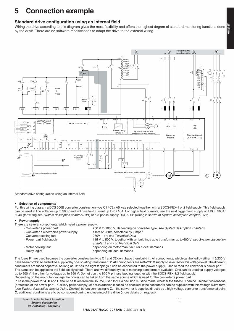
Standard drive configuration using an internal field
Standard drive configuration using an internal fieldWiring the drive according to this diagram gives the most flexibility and offers the highest degree of standard monitoring functions doneby the drive. There are no software modifications to adapt the drive to the external wiring.
• Selection of componentsFor this wiring diagram a DCS 500B converter construction type C1 / C2 / A5 was selected together with a SDCS-FEX-1 or 2 field supply. This field supplycan be used at line voltages up to 500V and will give field current up to 6 / 16A. For higher field currents, use the next bigger field supply unit DCF 503A/504A (for wiring see System description chapter 3.3/1) or a 3-phase supply DCF 500B (wiring is shown at System description chapter 3.5/2).
• Power supplyThere are several components, which need a power supply:
- Converter´s power part: 200 V to 1000 V, depending on converter type; see System description chapter 2- Converter´s electronics power supply: 115V or 230V, selectable by jumper- Converter cooling fan: 230V 1-ph; see Technical Data- Power part field supply: 115 V to 500 V; together with an isolating / auto transformer up to 600 V; see System description
chapter 2 and / or Technical Data- Motor cooling fan: depending on motor manufacturer / local demands- Relay logic: depending on local demands
The fuses F1 are used because the converter construction type C1 and C2 don´t have them build in. All components, which can be fed by either 115/230 Vhave been combined and will be supplied by one isolating transformer T2. All components are set to 230 V supply or selected for this voltage level. The differentconsumers are fused separate. As long as T2 has the right tappings it can be connected to the power supply, used to feed the converter´s power part.The same can be applied to the field supply circuit. There are two different types of matching transformers available. One can be used for supply voltagesup to 500 V, the other for voltages up to 690 V. Do not use the 690 V primary tapping together with the SDCS-FEX-1/2 field supply!Depending on the motor fan voltage the power can be taken from the same source which is used for the converter´s power part.In case the power for A, D and E should be taken from the source, used for C, a decision must be made, whether the fuses F1 can be used for two reasons(protection of the power part + auxiliary power supply) or not.In addition it has to be checked, if the consumers can be supplied with this voltage wave form(see System description chapter 2 Line Chokes) before connecting to C. If the converter is supplied directly by a high-voltage converter transformer at pointC, additional conditions are to be considered during engineering of the drive (more details on request).
IN3
OUT3
IN1
OUT1
V5
V6
V1
V2
X96:
DO8
1 2 X99: 1 2 X2: 4 5 X2: 1 2 3 U1 W1V1 PE
K1 F6
K20
K21K20 K3 K1
X96:1
X96:2
L1 L2 L3
F1
F3
K31 3
2 4
M~
T3F23
4
1
2
T2690V660V600V575V525V500V450V415V400V380V
115V
230V
K15
K15
S1
1
2
K6 K8
X2:4
X2:5
K11K10
K21
500V460V415V400V
365V350V265V250V90V60V30V
X33
C 1 D 1
AITAC AI1 AI2 AI3 AI4+10V -10V AO1 AO2 IACT DI1 DI2 DI3 DI4 DI5 DI6 DI7 DI8 +48V DO1 DO2 DO3 DO4 DO5 DO6 DO7_ _ _ _ _+ + + + +
T
T M
0V0V0V0V0V
X3: 1 2 3 4 5 6 7 8 9 10 X4: 1 2 3 4 5 6 7 8 9 10 X6: 1 2 3 4 5 6 7 8 9 10 X7: 1 2 3 4 5 6 7 8 1...10X5:+ _
+
_
K1
K20
K21
K6
K8
1
2S1
K11
K10
S4
5 6
2 4 6
1 3 5K6
F51
2F8
1
2F7
1
2
2
1
4
3
6
5F6
I > I > I >
13
14
UV
WM3~
K11 3 5
2 4 6
L1
1
2
3
4K8
13
14
X1: 1 7
L3
X1: 5 3+ _
L1 N L1 N L1 L2 L3
Voltage levelssee description
A C D E
Communication board (COM-x) Control board (CON-2)
Power supply(POW-1)
Convertermodule
ON
OFF STOP
START
EMER.STOP
Field exciter unit(SDCS-FEX-1/2)
depending on the unit typean other configuration is possible
the polarities are shown for motor operationif there are intermediate terminals
e.g. Pressure switch at C4
module
I 12 taken from/for further information:System description
3ADW000066 - chapter 3
• ControlThe relay logic can be split into three parts:
a: Generation of the ON/OFF and START/STOP command:The commands represented by K20 and K21 (latching interface relay) can be generated by a PLC and transferred to theterminals of the converter either by relays, giving galvanic isolation or directly by using 24V signals. There is no absoluteneed to use hardwired signals. These commands can be transferred via a serial link system too. Even a mixed solutioncan be realized by selecting the one or the other possibility for the one or the other signal.
b: Generation of control and monitoring signals:The main power contactor K1 for the armature circuit is controlled by a dry contact located on the electronic power supplyboard. The status of this contactor is checked by the converter via binary input 3. The field supply contactor K3 is controlledby the auxiliary contact K11 connected to a binary output of the converter. The binary outputs consist of relay drivers,capable to give appr. 50 mA each and a current limitation of around 160 mA for all of the outputs. The contactors K6 andK8 control the fans of the drive system. They are controlled by the auxiliary contact K10 (similar to K11). In series withK6 is an auxiliary contact of the circuit breaker F6, which monitors the motor fan supply. For the converter fan supplymonitoring the contact of the temperature detector is used in series with K8. Auxiliary contacts K6 and K8 are used andconnected to the binary inputs 1 and 2 to monitor the status of the fan supplies by the converter. The function of K15 isdescribed at the next point.
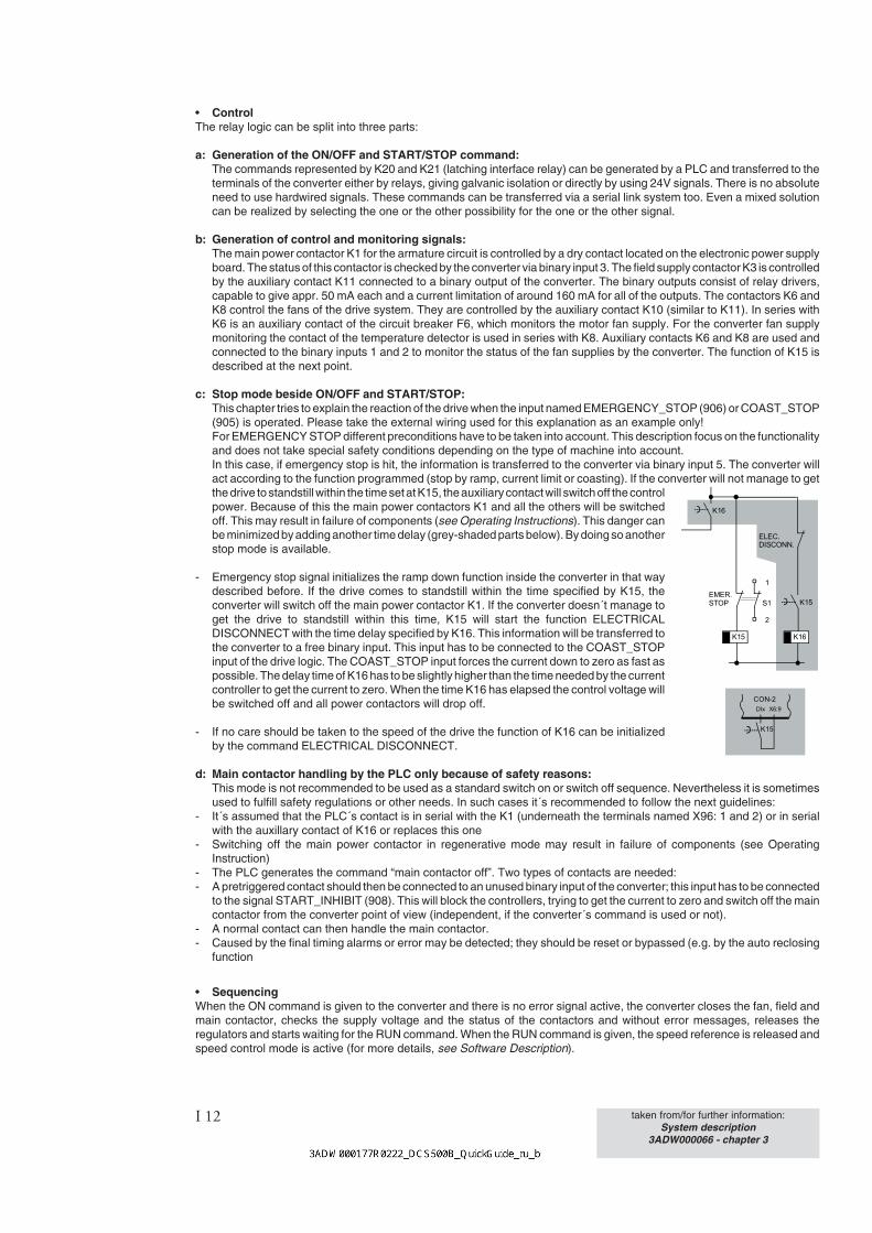
c: Stop mode beside ON/OFF and START/STOP:This chapter tries to explain the reaction of the drive when the input named EMERGENCY_STOP (906) or COAST_STOP(905) is operated. Please take the external wiring used for this explanation as an example only!For EMERGENCY STOP different preconditions have to be taken into account. This description focus on the functionalityand does not take special safety conditions depending on the type of machine into account.In this case, if emergency stop is hit, the information is transferred to the converter via binary input 5. The converter willact according to the function programmed (stop by ramp, current limit or coasting). If the converter will not manage to getthe drive to standstill within the time set at K15, the auxiliary contact will switch off the controlpower. Because of this the main power contactors K1 and all the others will be switchedoff. This may result in failure of components (see Operating Instructions). This danger canbe minimized by adding another time delay (grey-shaded parts below). By doing so anotherstop mode is available.
- Emergency stop signal initializes the ramp down function inside the converter in that waydescribed before. If the drive comes to standstill within the time specified by K15, theconverter will switch off the main power contactor K1. If the converter doesn´t manage toget the drive to standstill within this time, K15 will start the function ELECTRICALDISCONNECT with the time delay specified by K16. This information will be transferred tothe converter to a free binary input. This input has to be connected to the COAST_STOPinput of the drive logic. The COAST_STOP input forces the current down to zero as fast aspossible. The delay time of K16 has to be slightly higher than the time needed by the currentcontroller to get the current to zero. When the time K16 has elapsed the control voltage willbe switched off and all power contactors will drop off.
- If no care should be taken to the speed of the drive the function of K16 can be initializedby the command ELECTRICAL DISCONNECT.
d: Main contactor handling by the PLC only because of safety reasons:This mode is not recommended to be used as a standard switch on or switch off sequence. Nevertheless it is sometimesused to fulfill safety regulations or other needs. In such cases it´s recommended to follow the next guidelines:
- It´s assumed that the PLC´s contact is in serial with the K1 (underneath the terminals named X96: 1 and 2) or in serialwith the auxillary contact of K16 or replaces this one
- Switching off the main power contactor in regenerative mode may result in failure of components (see OperatingInstruction)
- The PLC generates the command “main contactor off”. Two types of contacts are needed:- A pretriggered contact should then be connected to an unused binary input of the converter; this input has to be connected
to the signal START_INHIBIT (908). This will block the controllers, trying to get the current to zero and switch off the maincontactor from the converter point of view (independent, if the converter´s command is used or not).
- A normal contact can then handle the main contactor.- Caused by the final timing alarms or error may be detected; they should be reset or bypassed (e.g. by the auto reclosing
function
• SequencingWhen the ON command is given to the converter and there is no error signal active, the converter closes the fan, field andmain contactor, checks the supply voltage and the status of the contactors and without error messages, releases theregulators and starts waiting for the RUN command. When the RUN command is given, the speed reference is released andspeed control mode is active (for more details, see Software Description).
EMER.STOP
K16
K15 K16
K15
ELEC.DISCONN.
DIx
K15
X6:9CON-2
S1
1
2
I 13
engl
ish
1. GeneralIn operation, drive converters, depending on their degree ofprotection, may have live, uninsulated, and possibly also movingor rotating parts, as well as hot surfaces.
In case of inadmissible removal of the required covers, ofimproper use, wrong installation or maloperation, there is thedanger of serious personal injury and damage to property.
For further information, see documentation.
All operations serving transport, installation and commissioninngas well as maintenance are to be carried out by skilled technicalpersonnel (Observe IEC 364 or CENELEC HD 384 or DIN VDE0100 and IEC 664 or DIN/VDE 0110 and national accidentprevention rules!).
For the purposes of these basic safety instructions, “skilledtechnical personnel” means persons who are familiar with theinstallation, mounting, commissioning and operation of theproduct and have the qualifications needed for the performanceof their functions.
2. Intended useDrive converters are components designed for inclusion inelectrical installations or machinery.
In case of installation in machinery, commissioning of the driveconverter (i.e. the starting of normal operation) is prohibited untilthe machinery has been proved to conform to the provisions ofthe directive 89/392/EEC (Machinery Safety Directive - MSD).Account is to be taken of EN 60204.
Commissioning (i.e. the starting of normal opertion) is admissibleonly where conformity with the EMC directive (89/336/EEC) hasbeen established.
The drive converters meet the requirements of the low-voltagedirective 73/23/EEC. They are subject to the harmonized stand-ards of the series prEN 50178/DIN VDE 0160 in conjunction withEN 60439-1/ VDE 0660, part 500, and EN 60146/ VDE 0558.
The technical data as well as information concerning the supplyconditions shall be taken from the rating plate and from thedocumentation and shall be strictly observed.
3. Transport, storageThe instructions for transport, storage and proper use shall becomplied with.
The climatic conditions shall be in conformity with prEN 50178.
4. InstallationThe installation and cooling of the appliances shall be in accord-ance with the specifications in the pertinent documentation.
The drive converters shall be protected against excessivestrains. In particular, no components must be bent or isolatingdistances altered in the course of transportation or handling. Nocontact shall be made with electronic components and contacts.
Drive converters contain electrostatic sensitive componentswhich are liable to damage through improper use. Electriccomponents must not be mechanically damaged or destroyed(potential health risks).
5. Electrical connectionWhen working on live drive converters, the applicable nationalaccident prevention rules (e.g. VBG 4) must be complied with.The electrical installation shall be carried out in accordance withthe relevant requirements (e.g. cross-sectional areas of conduc-tors, fusing, PE connection). For further information, see docu-mentation.
Instructions for the installation in accordance with EMC require-ments, like screening, earthing, location of filters and wiring, arecontained in the drive converter documentation. They mustalways be complied with, also for drive converters bearing a CEmarking. Observance of the limit values required by EMC law isthe responsibility of the manufacturer of the installation ormachine.
6. OperationInstallations which include drive converters shall be equippedwith additional control and protective devices in accordance withthe relevant applicable safety requirements, e.g. Act respectingtechnical equipment, accident prevention rules etc. Changes tothe drive converters by means of the operating software areadmissible.
After disconnection of the drive converter from the voltage supply,live appliance parts and power terminals must not be touchedimmediately because of possibly energized capacitors. In thisrespect, the corresponding signs and markings on the driveconverter must be respected.
During operation, all covers and doors shall be kept closed.
7. Maintenance and servicingThe manufacturer’s documentation shall be followed.
Keep safety instructions in a safe place!
6 Safety and operating instructions
for drive converters DCS / DCF / DCR
(in conformity with the low-voltage directive 73/23/EEC)
taken from/for further information:Safety instructions
3ADW000033
I 14
7 Short start-upOperating the panel
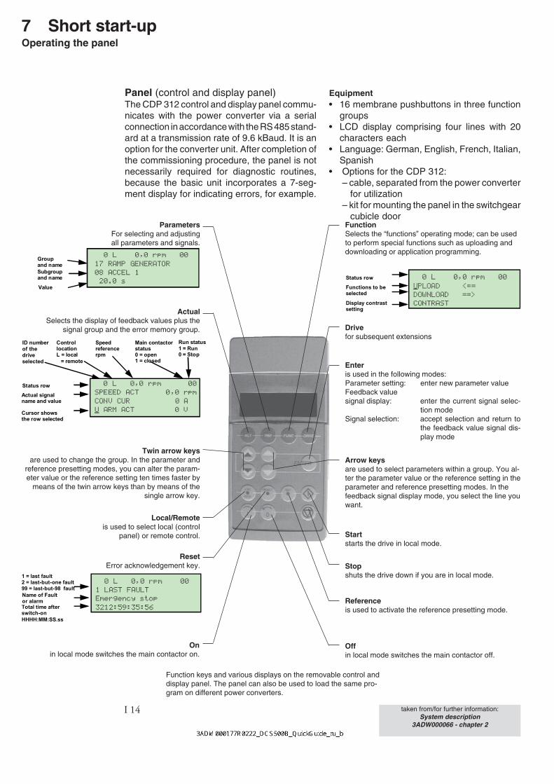
Panel (control and display panel)The CDP 312 control and display panel commu-nicates with the power converter via a serialconnection in accordance with the RS 485 stand-ard at a transmission rate of 9.6 kBaud. It is anoption for the converter unit. After completion ofthe commissioning procedure, the panel is notnecessarily required for diagnostic routines,because the basic unit incorporates a 7-seg-ment display for indicating errors, for example.
Function keys and various displays on the removable control anddisplay panel. The panel can also be used to load the same pro-gram on different power converters.
ActualSelects the display of feedback values plus the
signal group and the error memory group.
ParametersFor selecting and adjustingall parameters and signals.
FunctionSelects the “functions” operating mode; can be usedto perform special functions such as uploading anddownloading or application programming.
Drivefor subsequent extensions
Twin arrow keysare used to change the group. In the parameter and
reference presetting modes, you can alter the param-eter value or the reference setting ten times faster by
means of the twin arrow keys than by means of thesingle arrow key.
Arrow keysare used to select parameters within a group. You al-ter the parameter value or the reference setting in theparameter and reference presetting modes. In thefeedback signal display mode, you select the line youwant.
Enteris used in the following modes:Parameter setting: enter new parameter valueFeedback valuesignal display: enter the current signal selec-
tion modeSignal selection: accept selection and return to
the feedback value signal dis-play mode
Local/Remoteis used to select local (control
panel) or remote control.
ResetError acknowledgement key.
Referenceis used to activate the reference presetting mode.
Startstarts the drive in local mode.
Stopshuts the drive down if you are in local mode.
Onin local mode switches the main contactor on.
Offin local mode switches the main contactor off.
Equipment• 16 membrane pushbuttons in three function
groups• LCD display comprising four lines with 20
characters each• Language: German, English, French, Italian,
Spanish• Options for the CDP 312:
– cable, separated from the power converterfor utilization
– kit for mounting the panel in the switchgearcubicle door
0 L 0,0 rpm 001 LAST FAULTEmergency stop3212:59:35:56
1 = last fault2 = last-but-one fault99 = last-but-98 fault
Total time afterswitch-on HHHH:MM:SS.ss
Name of Fault or alarm
Status row
Functions to be selected
Display contrastsetting
0 L 0,0 rpm 00UPLOAD <==DOWNLOAD ==>CONTRAST
Groupand nameSubgroupand name
0 L 0,0 rpm 0017 RAMP GENERATOR08 ACCEL 1 20.0 s
Value
ID number of thedriveselected
ControllocationL = local = remote
Main contactorstatus0 = open1 = closed
Speedreferencerpm
Run status1 = Run0 = Stop
Status rowActual signalname and value
Cursor showsthe row selected
0 L 0,0 rpm 00SPEEED ACT 0,0 rpmCONV CUR 0 AU ARM ACT 0 V
taken from/for further information:System description
3ADW000066 - chapter 2
I 15
engl
ish
Start-up
taken from/for further information:Operating instructions
3ADW000055 - chapter 2
Danger! High voltage: this sym-bol warns of high voltages whichmay result in injuries to personsand/or damage to equipment. Thetext beside this symbol describes,where appropriate, options foravoiding this hazard.
General warning: this symbolwarns of non-electrical dangers,which may result in serious oreven fatal injuries to persons and/or damage to equipment. Thetext beside this symbol describes,where appropriate, options foravoiding this hazard.
Warning of electrostatic dis-charge: this symbol warns ofelectrostatic discharges whichmay result in damage to equip-ment. The text beside this symboldescribes, where appropriate, op-tions for avoiding this hazard.
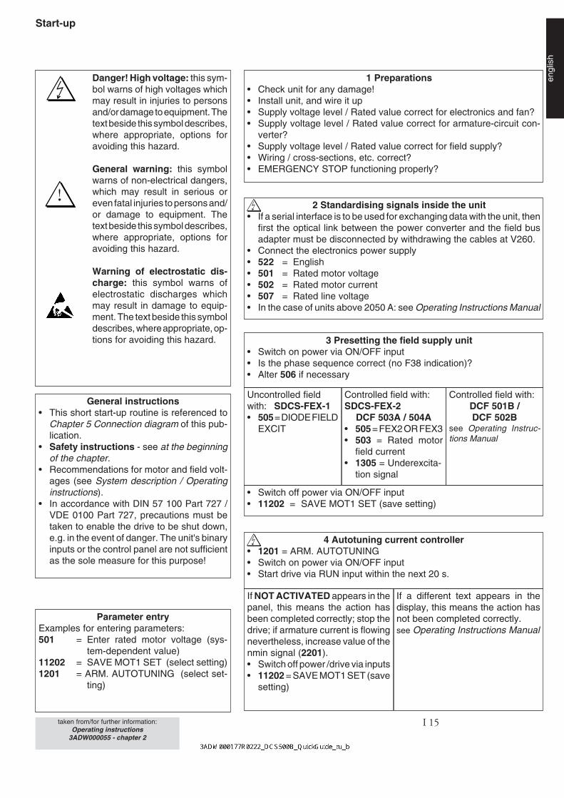
1 Preparations• Check unit for any damage!• Install unit, and wire it up• Supply voltage level / Rated value correct for electronics and fan?• Supply voltage level / Rated value correct for armature-circuit con-
verter?• Supply voltage level / Rated value correct for field supply?• Wiring / cross-sections, etc. correct?• EMERGENCY STOP functioning properly?
2 Standardising signals inside the unit• If a serial interface is to be used for exchanging data with the unit, then
first the optical link between the power converter and the field busadapter must be disconnected by withdrawing the cables at V260.
• Connect the electronics power supply• 522 = English• 501 = Rated motor voltage• 502 = Rated motor current• 507 = Rated line voltage• In the case of units above 2050 A: see Operating Instructions Manual
3 Presetting the field supply unit• Switch on power via ON/OFF input• Is the phase sequence correct (no F38 indication)?• Alter 506 if necessary
Uncontrolled fieldwith: SDCS-FEX-1• 505 = DIODE FIELD
EXCIT
Controlled field with:SDCS-FEX-2
DCF 503A / 504A• 505 = FEX2 OR FEX3• 503 = Rated motor
field current• 1305 = Underexcita-
tion signal
Controlled field with:DCF 501B /DCF 502B
see Operating Instruc-tions Manual
• Switch off power via ON/OFF input• 11202 = SAVE MOT1 SET (save setting)
4 Autotuning current controller• 1201 = ARM. AUTOTUNING• Switch on power via ON/OFF input• Start drive via RUN input within the next 20 s.
If NOT ACTIVATED appears in thepanel, this means the action hasbeen completed correctly; stop thedrive; if armature current is flowingnevertheless, increase value of thenmin signal (2201).• Switch off power /drive via inputs• 11202 = SAVE MOT1 SET (save
setting)
If a different text appears in thedisplay, this means the action hasnot been completed correctly.see Operating Instructions Manual
Parameter entryExamples for entering parameters:501 = Enter rated motor voltage (sys-
tem-dependent value)11202 = SAVE MOT1 SET (select setting)1201 = ARM. AUTOTUNING (select set-
ting)
General instructions• This short start-up routine is referenced to
Chapter 5 Connection diagram of this pub-lication.
• Safety instructions - see at the beginningof the chapter.
• Recommendations for motor and field volt-ages (see System description / Operatinginstructions).
• In accordance with DIN 57 100 Part 727 /VDE 0100 Part 727, precautions must betaken to enable the drive to be shut down,e.g. in the event of danger. The unit's binaryinputs or the control panel are not sufficientas the sole measure for this purpose!
I 16 taken from/for further information:Operating instructions
3ADW000055 - chapter 2
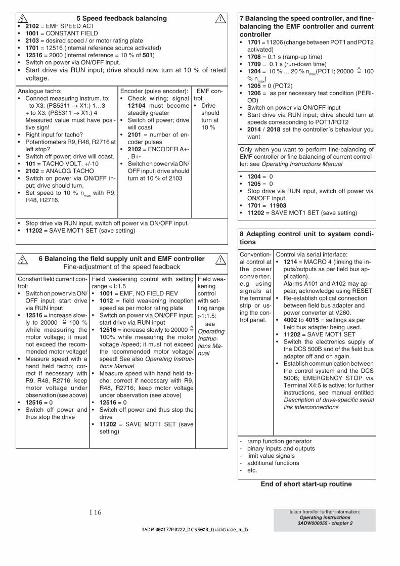
5 Speed feedback balancing• 2102 = EMF SPEED ACT• 1001 = CONSTANT FIELD• 2103 = desired speed / or motor rating plate• 1701 = 12516 (internal reference source activated)• 12516 = 2000 (internal reference = 10 % of 501)• Switch on power via ON/OFF input.• Start drive via RUN input; drive should now turn at 10 % of rated
voltage.
Analogue tacho:• Connect measuring instrum. to:
- to X3: (PS5311 → X1:) 1…3+ to X3: (PS5311 → X1:) 4Measured value must have posi-tive sign!
• Right input for tacho?• Potentiometers R9, R48, R2716 at
left stop?• Switch off power; drive will coast.• 101 = TACHO VOLT. +/-10• 2102 = ANALOG TACHO• Switch on power via ON/OFF in-
put; drive should turn.• Set speed to 10 % nmax with R9,
R48, R2716.
Encoder (pulse encoder):• Check wiring; signal
12104 must becomesteadily greater
• Switch off power; drivewill coast
• 2101 = number of en-coder pulses
• 2102 = ENCODER A+-, B+-
• Switch on power via ON/OFF input; drive shouldturn at 10 % of 2103
EMF con-trol:• Drive
shouldturn at10 %
• Stop drive via RUN input, switch off power via ON/OFF input.• 11202 = SAVE MOT1 SET (save setting)
7 Balancing the speed controller, and fine-balancing the EMF controller and currentcontroller• 1701 = 11206 (change between POT1 and POT2
activated)• 1708 = 0.1 s (ramp-up time)• 1709 = 0.1 s (run-down time)• 1204 = 10 % … 20 % nmax(POT1; 20000 = 100
% nmax)• 1205 = 0 (POT2)• 1206 = as per necessary test condition (PERI-
OD)• Switch on power via ON/OFF input• Start drive via RUN input; drive should turn at
speeds corresponding to POT1/POT2• 2014 / 2018 set the controller´s behaviour you
want
Only when you want to perform fine-balancing ofEMF controller or fine-balancing of current control-ler: see Operating Instructions Manual
• 1204 = 0• 1205 = 0• Stop drive via RUN input, switch off power via
ON/OFF input• 1701 = 11903• 11202 = SAVE MOT1 SET (save setting)
8 Adapting control unit to system condi-tions
6 Balancing the field supply unit and EMF controllerFine-adjustment of the speed feedback
Constant field current con-trol:• Switch on power via ON/
OFF input; start drivevia RUN input
• 12516 = increase slow-ly to 20000 = 100 %while measuring themotor voltage; it mustnot exceed the recom-mended motor voltage!
• Measure speed with ahand held tacho; cor-rect if necessary withR9, R48, R2716; keepmotor voltage underobservation (see above)
• 12516 = 0• Switch off power and
thus stop the drive
Field weakening control with settingrange <1:1.5• 1001 = EMF, NO FIELD REV• 1012 = field weakening inception
speed as per motor rating plate• Switch on power via ON/OFF input;
start drive via RUN input• 12516 = increase slowly to 20000 =
100% while measuring the motorvoltage /speed; it must not exceedthe recommended motor voltage/speed! See also Operating Instruc-tions Manual
• Measure speed with hand held ta-cho; correct if necessary with R9,R48, R2716; keep motor voltageunder observation (see above)
• 12516 = 0• Switch off power and thus stop the
drive• 11202 = SAVE MOT1 SET (save
setting)
Field wea-keningcontrolwith set-ting range>1:1.5:
seeOperatingInstruc-tions Ma-nual
Convention-al control atthe powerconverter,e.g usingsignals atthe terminalstrip or us-ing the con-trol panel.
Control via serial interface:• 1214 = MACRO 4 (linking the in-
puts/outputs as per field bus ap-plication).Alarms A101 and A102 may ap-pear; acknowledge using RESET
• Re-establish optical connectionbetween field bus adapter andpower converter at V260.
• 4002 to 4015 = settings as perfield bus adapter being used.
• 11202 = SAVE MOT1 SET• Switch the electronics supply of
the DCS 500B and of the field busadapter off and on again.
• Establish communication betweenthe control system and the DCS500B; EMERGENCY STOP viaTerminal X4:5 is active; for furtherinstructions, see manual entitledDescription of drive-specific seriallink interconnections
- ramp function generator- binary inputs and outputs- limit value signals- additional functions- etc.
End of short start-up routine
I 17
engl
ish
8 Status messages
Categories of mes-sages and display options
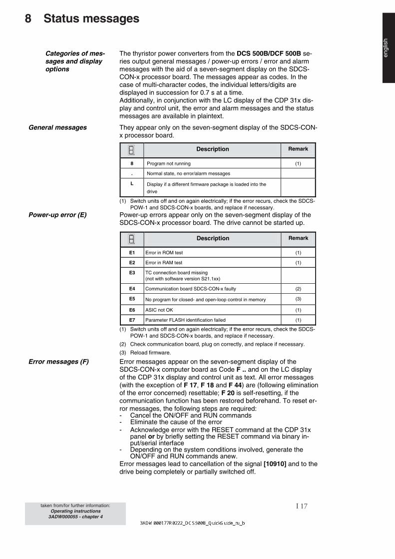
The thyristor power converters from the DCS 500B/DCF 500B se-ries output general messages / power-up errors / error and alarm messages with the aid of a seven-segment display on the SDCS-CON-x processor board. The messages appear as codes. In the case of multi-character codes, the individual letters/digits are displayed in succession for 0.7 s at a time. Additionally, in conjunction with the LC display of the CDP 31x dis-play and control unit, the error and alarm messages and the status messages are available in plaintext.
General messages
They appear only on the seven-segment display of the SDCS-CON-x processor board.
Description Remark
8 Program not running (1)
. Normal state, no error/alarm messages
L Display if a different firmware package is loaded into the
drive
(1) Switch units off and on again electrically; if the error recurs, check the SDCS-POW-1 and SDCS-CON-x boards, and replace if necessary.
Power-up error (E)
Power-up errors appear only on the seven-segment display of the SDCS-CON-x processor board. The drive cannot be started up.
Description Remark
E1 Error in ROM test (1)
E2 Error in RAM test (1)
E3 TC connection board missing (not with software version S21.1xx)
E4 Communication board SDCS-CON-x faulty (2)
E5 No program for closed- and open-loop control in memory (3)
E6 ASIC not OK (1)
E7 Parameter FLASH identification failed (1)
(1) Switch units off and on again electrically; if the error recurs, check the SDCS-POW-1 and SDCS-CON-x boards, and replace if necessary.
(2) Check communication board, plug on correctly, and replace if necessary.
(3) Reload firmware. Error messages (F)
Error messages appear on the seven-segment display of the SDCS-CON-x computer board as Code F .. and on the LC display of the CDP 31x display and control unit as text. All error messages (with the exception of F 17, F 18 and F 44) are (following elimination of the error concerned) resettable; F 20 is self-resetting, if the communication function has been restored beforehand. To reset er-ror messages, the following steps are required: - Cancel the ON/OFF and RUN commands - Eliminate the cause of the error - Acknowledge error with the RESET command at the CDP 31x
panel or by briefly setting the RESET command via binary in-put/serial interface
- Depending on the system conditions involved, generate the ON/OFF and RUN commands anew.
Error messages lead to cancellation of the signal [10910] and to the drive being completely or partially switched off.
taken from/for further information:Operating instructions
3ADW000055 - chapter 4
I 18
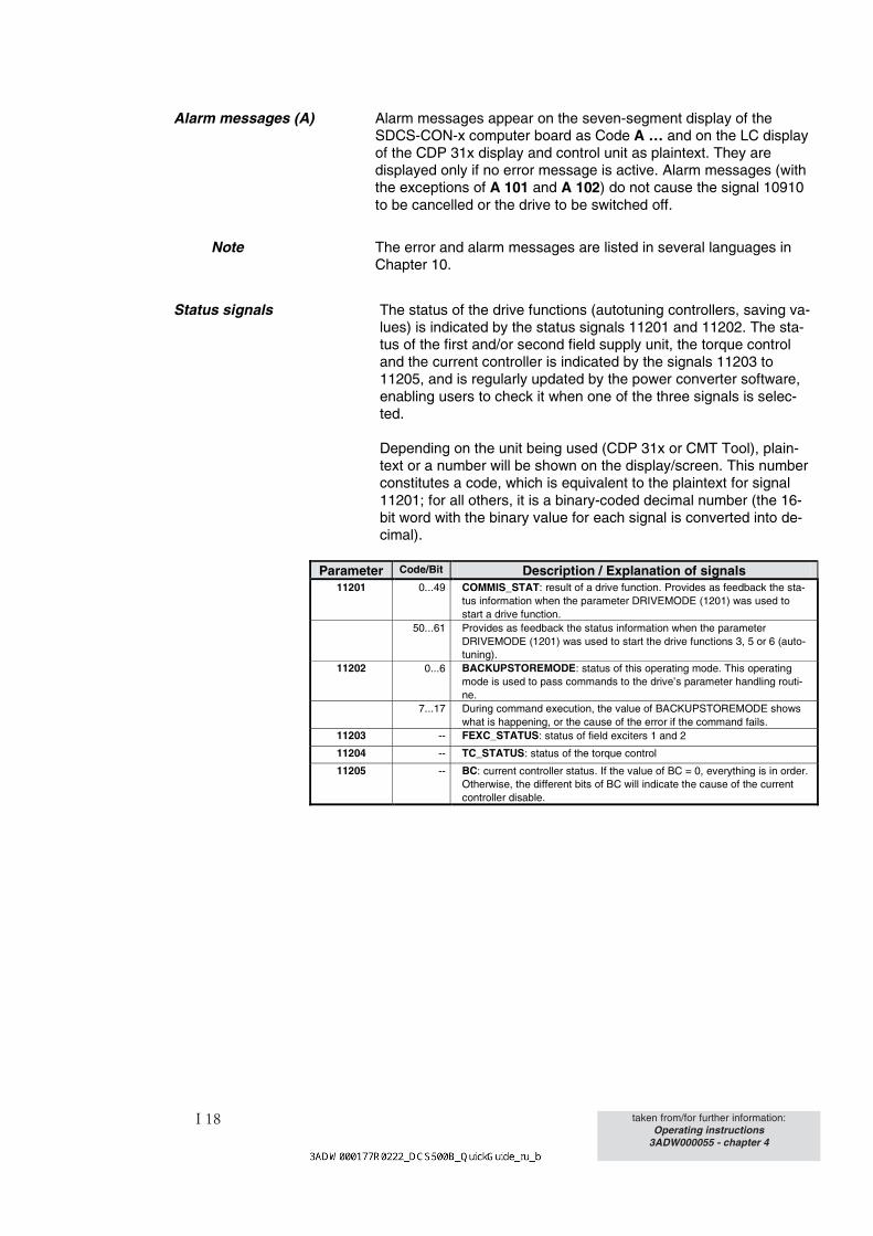
Alarm messages (A)
Alarm messages appear on the seven-segment display of the SDCS-CON-x computer board as Code A … and on the LC display of the CDP 31x display and control unit as plaintext. They are displayed only if no error message is active. Alarm messages (with the exceptions of A 101 and A 102) do not cause the signal 10910 to be cancelled or the drive to be switched off.
Note The error and alarm messages are listed in several languages in Chapter 10.
Status signals
The status of the drive functions (autotuning controllers, saving va-lues) is indicated by the status signals 11201 and 11202. The sta-tus of the first and/or second field supply unit, the torque control and the current controller is indicated by the signals 11203 to 11205, and is regularly updated by the power converter software, enabling users to check it when one of the three signals is selec-ted. Depending on the unit being used (CDP 31x or CMT Tool), plain-text or a number will be shown on the display/screen. This number constitutes a code, which is equivalent to the plaintext for signal 11201; for all others, it is a binary-coded decimal number (the 16-bit word with the binary value for each signal is converted into de-cimal).
Parameter Code/Bit Description / Explanation of signals
11201 0...49 COMMIS_STAT: result of a drive function. Provides as feedback the sta-tus information when the parameter DRIVEMODE (1201) was used to start a drive function.
50...61 Provides as feedback the status information when the parameter DRIVEMODE (1201) was used to start the drive functions 3, 5 or 6 (auto-tuning).
11202 0...6 BACKUPSTOREMODE: status of this operating mode. This operating mode is used to pass commands to the drive’s parameter handling routi-ne.
7...17 During command execution, the value of BACKUPSTOREMODE shows what is happening, or the cause of the error if the command fails.
11203 -- FEXC_STATUS: status of field exciters 1 and 2
11204 -- TC_STATUS: status of the torque control
11205 -- BC: current controller status. If the value of BC = 0, everything is in order. Otherwise, the different bits of BC will indicate the cause of the current controller disable.
taken from/for further information:Operating instructions
3ADW000055 - chapter 4
I 19
deut
sch
R
NRTL /C
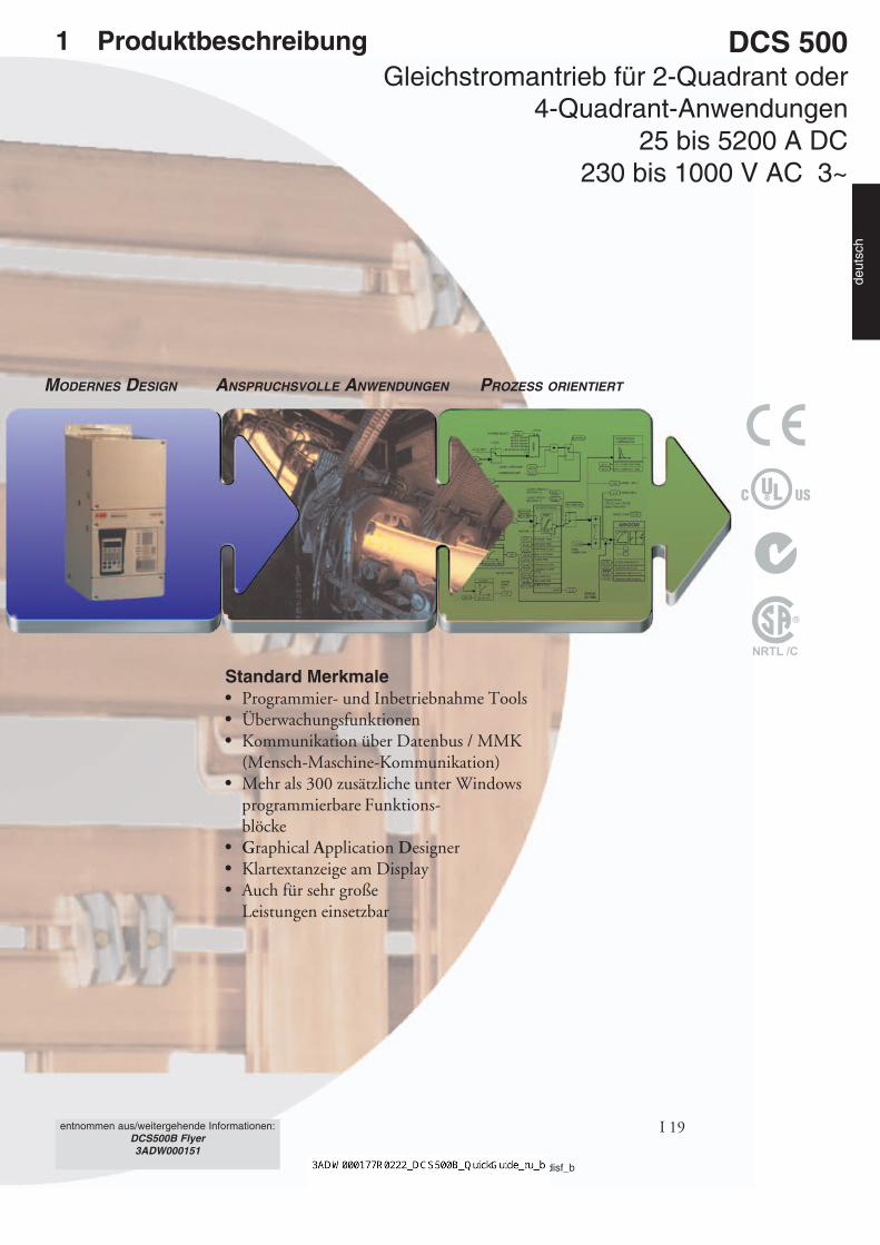
DCS 500Gleichstromantrieb für 2-Quadrant oder
4-Quadrant-Anwendungen25 bis 5200 A DC
230 bis 1000 V AC 3~
MODERNES DESIGN ANSPRUCHSVOLLE ANWENDUNGEN PROZESS ORIENTIERT
Standard Merkmale• Programmier- und Inbetriebnahme Tools• Überwachungsfunktionen• Kommunikation über Datenbus / MMK
(Mensch-Maschine-Kommunikation)• Mehr als 300 zusätzliche unter Windows
programmierbare Funktions-blöcke
• Graphical Application Designer• Klartextanzeige am Display• Auch für sehr große
Leistungen einsetzbar
I 19
1 Produktbeschreibung
entnommen aus/weitergehende Informationen:DCS500B Flyer3ADW000151
3ADW000177R0200_DCS500B_QuickGuide_edisf_b
I 20 entnommen aus/weitergehende Informationen:DCS500B Flyer3ADW000151
DCS 500 Stromrichter sind alsModul oder im Schaltschrankals DCA 500 verfügbar.
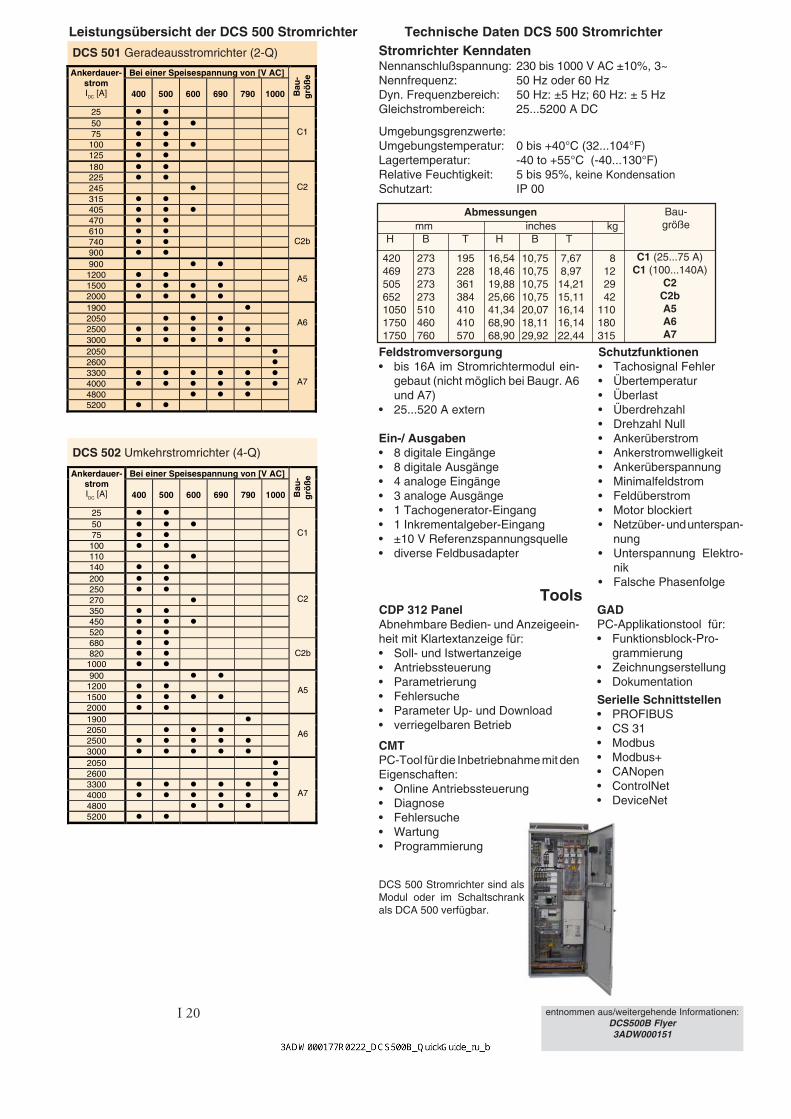
Technische Daten DCS 500 StromrichterLeistungsübersicht der DCS 500 StromrichterStromrichter KenndatenNennanschlußspannung: 230 bis 1000 V AC ±10%, 3~Nennfrequenz: 50 Hz oder 60 HzDyn. Frequenzbereich: 50 Hz: ±5 Hz; 60 Hz: ± 5 HzGleichstrombereich: 25...5200 A DC
Umgebungsgrenzwerte:Umgebungstemperatur: 0 bis +40°C (32...104°F)Lagertemperatur: -40 to +55°C (-40...130°F)Relative Feuchtigkeit: 5 bis 95%, keine KondensationSchutzart: IP 00
Feldstromversorgung• bis 16A im Stromrichtermodul ein-
gebaut (nicht möglich bei Baugr. A6und A7)
• 25...520 A extern
Ein-/ Ausgaben• 8 digitale Eingänge• 8 digitale Ausgänge• 4 analoge Eingänge• 3 analoge Ausgänge• 1 Tachogenerator-Eingang• 1 Inkrementalgeber-Eingang• ±10 V Referenzspannungsquelle• diverse Feldbusadapter
Schutzfunktionen• Tachosignal Fehler• Übertemperatur• Überlast• Überdrehzahl• Drehzahl Null• Ankerüberstrom• Ankerstromwelligkeit• Ankerüberspannung• Minimalfeldstrom• Feldüberstrom• Motor blockiert• Netzüber- und unterspan-
nung• Unterspannung Elektro-
nik• Falsche Phasenfolge
CDP 312 PanelAbnehmbare Bedien- und Anzeigeein-heit mit Klartextanzeige für:• Soll- und Istwertanzeige• Antriebssteuerung• Parametrierung• Fehlersuche• Parameter Up- und Download• verriegelbaren Betrieb
CMTPC-Tool für die Inbetriebnahme mit denEigenschaften:• Online Antriebssteuerung• Diagnose• Fehlersuche• Wartung• Programmierung
DCS 502 Umkehrstromrichter (4-Q)
DCS 501 Geradeausstromrichter (2-Q)
GADPC-Applikationstool für:• Funktionsblock-Pro-
grammierung• Zeichnungserstellung• Dokumentation
Tools
Serielle Schnittstellen• PROFIBUS• CS 31• Modbus• Modbus+• CANopen• ControlNet• DeviceNet
Bei einer Speisespannung von [V AC] Ankerdauer- strom IDC [A]
400
500
600
690
790
1000 B
au-
grö
ße
25 50 75 100 125
C1
180 225 245 315 405 470
C2
610 740 900
C2b
900 1200 1500 2000
A5
1900 2050 2500 3000
A6
2050 2600 3300 4000 4800 5200
A7
Bei einer Speisespannung von [V AC] Ankerdauer- strom IDC
[A]
400
500
600
690
790
1000 Bau
-g
röß
e
25 50 75 100 110 140
C1
200 250 270 350 450 520
C2
680 820
1000
C2b
900 1200 1500 2000
A5
1900 2050 2500 3000
A6
2050 2600 3300 4000 4800 5200
A7
Bau-größe
C1 (25...75 A)C1 (100...140A)
C2C2bA5A6A7
Abmessungenmm inches kg
H B T H B T
420 273 195 16,54 10,75 7,67 8469 273 228 18,46 10,75 8,97 12505 273 361 19,88 10,75 14,21 29652 273 384 25,66 10,75 15,11 421050 510 410 41,34 20,07 16,14 1101750 460 410 68,90 18,11 16,14 1801750 760 570 68,90 29,92 22,44 315
I 21
deut
sch
2 Hinweise, Kurzanweisung CD und Dokumentationsübersicht
Wir freuen uns, dass Sie einen ABB DC-An-triebsstromrichter erworben haben und bedan-ken uns für Ihr Vertrauen, das Sie unserenProdukten entgegengebracht haben.
Damit Sie auch weiterhin mit unserem Produktzufrieden sind, haben wir diese Broschüre fürSie zusammengestellt. Sie soll hauptsächlichdazu dienen, ihnen einen Kurzüberblick zu ver-schaffen über die Produktkenndaten, EMV Hin-weise, Anwendungsbeispiele, Inbetriebnahmeund Fehlererkennung.
Benötigen Sie weitere Informationen zum Pro-dukt, haben Sie zusätzlich zu dieser Kurz-Doku-mentation eine CD ROM (diese CD ROM istintegraler Bestandteil dieser Dokumentation) inden fünf Hauptsprachen englisch, deutsch, ita-lienisch, spanisch und französisch mit folgen-dem Inhalt zur Verfügung:
Dokumentation
zu unseren Produktreihen:• DCS400• DCS500• DCS600
Unsere Dokumentation ist grundsätzlich nachfolgender Systematik aufgebaut:
Systembeschreibungals umfassende Information zur Planung desGesamtsystems Stromrichter.
Technische Datenals Detailinformation mit allen wichtigen Anga-ben zu den Einzelkomponenten, wie Modulab-maße, Elektronikkarten, Lüfter und Zusatzkom-ponenten.
Betriebsanleitungmit allen notwendigen Informationen zur Inbe-triebnahme und Wartung des Gesamtantriebesin detaillierter Form.
Softwarebeschreibung plus Applikations-blocksnur notwendig für das Programmieren des An-triebes, nur in englischer Sprache und nicht ingedruckter Form verfügbar.
Service Manualfür die Wartung und Reparatur der Geräte.
Sowie diverse Informationen zu Anwendun-gen ( z.B. 12-Puls ) und technischem Zubehöretc.
Systemvoraussetzungen für dieNutzung der CD ROM
• Betriebssystem WINDOWS 98, NT, 2000,XP
• ACROBAT READER 4.0 ausreichend (emp-fehlenswert 5.0 - auf der CD ROM enthalten)
• INTERNET Explorer 5.0 oder eine spätereVersion
Falls die CD Rom nicht automatisch startensollte, bitte Doppel-Klick auf START.HTM
Weitere Unterstützung
Wir bieten Ihnen darüber hinaus weitere Unter-stützung an, denn nur wenn Sie als Kunde mituns und Ihrer Entscheidung zufrieden sind, kön-nen auch wir zufrieden sein.
InternetAuf der ABB Home page unter
www.abb.com/dc
finden Sie viele verfügbare Informationen zu• DC Produkten• Service• neueste Updates• Tools• Downloads etc.Bitte zögern Sie nicht uns dort zu besuchen.
KontakteBenötigen Sie weitere Informationen, sprechenSie bitte Ihr nächstgelegenes ABB Drives Büroan oderSchreiben Sie eine E-Mail an:
Geben Sie uns bitte Ihren Namen, Ihre Firma,Adresse und Telefonnummer an und wir wer-den Ihnen umgehend den für Sie zuständigenAnsprechpartner mitteilen.
I 22
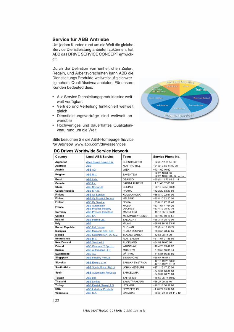
Service für ABB AntriebeUm jedem Kunden rund um die Welt die gleicheService Dienstleistung anbieten zukönnen, hatABB das DRIVE SERVICE CONCEPT entwick-elt.
Durch die Definition von einheitlichen Zielen,Regeln, und Arbeitsvorschriften kann ABB dieDienstleitungs Produkte weltweit auf gleichwer-tig hohem Qualitätsnivea anbieten. Für unsereKunden bedeuted dies:
• Alle Service Diensleitungsprodukte sind welt-weit verfügbar.
• Vertrieb und Verteilung funktioniert weltweitgleich
• Dienstleistungsverträge sind weltweit an-wendbar
• Hochwertiges und dauerhaftes Qualitätsni-veau rund um die Welt
Bitte besuchen Sie die ABB-Homepage Servicefür Antriebe www.abb.com/drivesservices
DC Drives Worldwide Service Network Country Local ABB Service Town Service Phone No. Argentina Asea Brown Boveri S.A. BUENOS AIRES +54 (0) 12 29 55 00 Australia ABB NOTTING HILL +61 (0) 3 85 44 00 00 Austria ABB AG WIEN +43 1 60 10 90
Belgium ABB N.V. ZAVENTEM +32 27 18 64 86 +32 27 18 65 00 - 24h service
Brazil ABB Ltda. OSASCO +55 (0) 11 70 84 91 11 Canada ABB Inc. SAINT-LAURENT +1 51 48 32 65 00 China ABB China Ltd BEIJING +86 10 84 56 66 88 Czech Republic ABB S.R.O. PRAHA +42 2 22 83 23 60 Finland ABB Oy Service KUUSANKOSKI +35 8 10 22 51 00 Finland ABB Oy Product Service HELSINKI +35 8 10 22 20 00 Finland ABB Oy Service NOKIA +35 8 10 22 51 40
France ABB Automation ABB Process Industry
MASSY DECINES
+33 1 64 47 64 26 +33 4 72 05 40 76
Germany ABB Process Industries MANNHEIM +49 18 05 12 35 80 Greece ABB SA METAMORPHOSSIS +30 1 02 89 16 51 Ireland ABB Ireland Ltd. TALLAGHT +35 3 14 05 73 00 Italy ABB MILAN +39 02 90 34 73 91 Korea, Republic ABB Ltd., Korea CHONAN +82 (0) 4 15 29 22 Malaysia ABB Malaysia Sdn. Bhd. KUALA LUMPUR +60 3 56 28 42 65 Mexico ABB Sistemas S.A. DE C.V. TLALNEPANTLA +52 53 28 14 00 Netherlands ABB B.V. ROTTERDAM +31 1 04 07 88 66 New Zealand ABB Service ltd AUCKLAND +64 92 76 60 16 Poland ABB Centrum IT Sp.zo.o WROCLAW +48 4 26 13 49 62 Russia ABB Automation LLC MOSCOW +7 09 59 56 05 44 Switzerland ABB AG DÄTTWIL +41 5 85 86 87 86 Singapore ABB Industry Pte Ltd SINGAPORE +65 67 76 57 11
Slovakia ABB Elektro s.r.o. BANSKA BYSTRICA +42 12 49 26 63 69 +42 12 49 26 61 11
South Africa ABB South Africa (Pty) Lt JOHANNESBURG +27 1 16 17 20 00
Spain ABB Automation Products BARCELONA +34 9 37 28 87 00 +34 9 37 28 73 00
Taiwan ABB Ltd. TAIPEI 105 +88 62 25 77 60 90 Thailand ABB Limited SAMUTPRAKARN +66 27 09 33 46 Turkey ABB Elektirk Sanayi A.S ISTANBUL +90 2 16 36 52 90 USA ABB Industrial Products NEW BERLIN +1 26 27 85 32 00 Venezuela ABB S.A. CARACAS +58 (0) 22 38 24 11 / 12
I 23
deut
sch
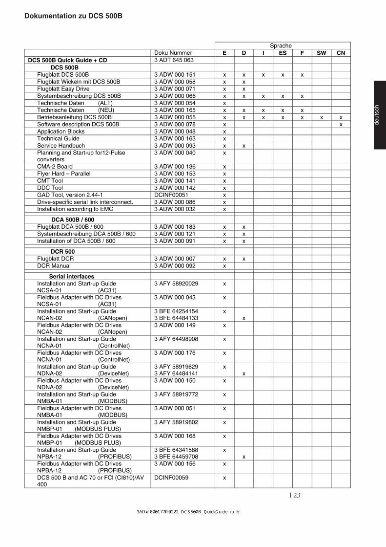
Dokumentation zu DCS 500B
Sprache Doku Nummer E D I ES F SW CN DCS 500B Quick Guide + CD 3 ADT 645 063 DCS 500B
Flugblatt DCS 500B 3 ADW 000 151 x x x x x Flugblatt Wickeln mit DCS 500B 3 ADW 000 058 x x Flugblatt Easy Drive 3 ADW 000 071 x x Systembeschreibung DCS 500B 3 ADW 000 066 x x x x x Technische Daten (ALT) 3 ADW 000 054 x Technische Daten (NEU) 3 ADW 000 165 x x x x x Betriebsanleitung DCS 500B 3 ADW 000 055 x x x x x x x Software description DCS 500B 3 ADW 000 078 x x Application Blocks 3 ADW 000 048 x Technical Guide 3 ADW 000 163 x Service Handbuch 3 ADW 000 093 x x Planning and Start-up for12-Pulse converters
3 ADW 000 040 x
CMA-2 Board 3 ADW 000 136 x Flyer Hard – Parallel 3 ADW 000 153 x CMT Tool 3 ADW 000 141 x DDC Tool 3 ADW 000 142 x GAD Tool, version 2.44-1 DCINF00051 x Drive-specific serial link interconnect. 3 ADW 000 086 x Installation according to EMC 3 ADW 000 032 x
DCA 500B / 600 Flugblatt DCA 500B / 600 3 ADW 000 183 x x Systembeschreibung DCA 500B / 600 3 ADW 000 121 x x Installation of DCA 500B / 600 3 ADW 000 091 x x
DCR 500 Flugblatt DCR 3 ADW 000 007 x x DCR Manual 3 ADW 000 092 x
Serial interfaces Installation and Start-up Guide NCSA-01 (AC31)
3 AFY 58920029 x
Fieldbus Adapter with DC Drives NCSA-01 (AC31)
3 ADW 000 043 x
Installation and Start-up Guide NCAN-02 (CANopen)
3 BFE 64254154 3 BFE 64484133
x x
Fieldbus Adapter with DC Drives NCAN-02 (CANopen)
3 ADW 000 149 x
Installation and Start-up Guide NCNA-01 (ControlNet)
3 AFY 64498908 x
Fieldbus Adapter with DC Drives NCNA-01 (ControlNet)
3 ADW 000 176 x
Installation and Start-up Guide NDNA-02 (DeviceNet)
3 AFY 58919829 3 AFY 64484141
x x
Fieldbus Adapter with DC Drives NDNA-02 (DeviceNet)
3 ADW 000 150 x
Installation and Start-up Guide NMBA-01 (MODBUS)
3 AFY 58919772 x
Fieldbus Adapter with DC Drives NMBA-01 (MODBUS)
3 ADW 000 051 x
Installation and Start-up Guide NMBP-01 (MODBUS PLUS)
3 AFY 58919802 x
Fieldbus Adapter with DC Drives NMBP-01 (MODBUS PLUS)
3 ADW 000 168 x
Installation and Start-up Guide NPBA-12 (PROFIBUS)
3 BFE 64341588 3 BFE 64459708
x x
Fieldbus Adapter with DC Drives NPBA-12 (PROFIBUS)
3 ADW 000 156 x
DCS 500 B and AC 70 or FCI (CI810)/AV 400
DCINF00059 x
I 24
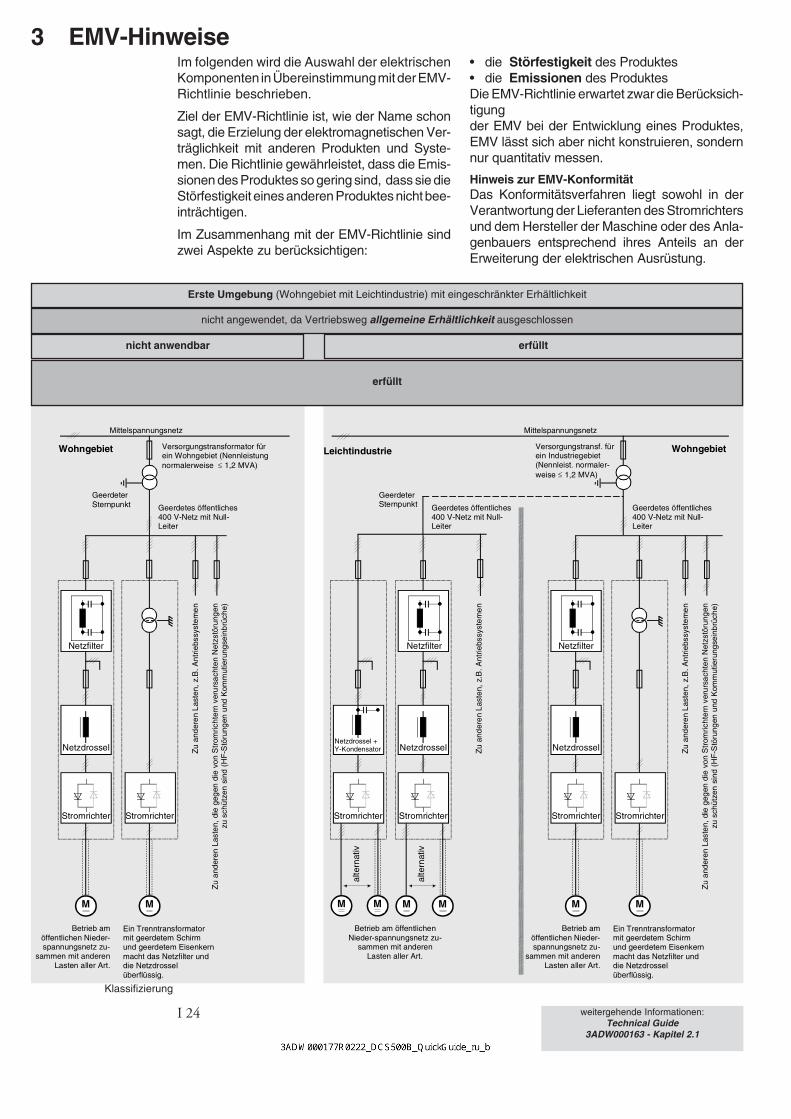
3 EMV-Hinweise
Klassifizierung
nicht anwendbar
Erste Umgebung (Wohngebiet mit Leichtindustrie) mit eingeschränkter Erhältlichkeit
nicht angewendet, da Vertriebsweg allgemeine Erhältlichkeit ausgeschlossen
erfüllt
erfüllt
Im folgenden wird die Auswahl der elektrischenKomponenten in Übereinstimmung mit der EMV-Richtlinie beschrieben.
Ziel der EMV-Richtlinie ist, wie der Name schonsagt, die Erzielung der elektromagnetischen Ver-träglichkeit mit anderen Produkten und Syste-men. Die Richtlinie gewährleistet, dass die Emis-sionen des Produktes so gering sind, dass sie dieStörfestigkeit eines anderen Produktes nicht bee-inträchtigen.
Im Zusammenhang mit der EMV-Richtlinie sindzwei Aspekte zu berücksichtigen:
• die Störfestigkeit des Produktes• die Emissionen des ProduktesDie EMV-Richtlinie erwartet zwar die Berücksich-tigungder EMV bei der Entwicklung eines Produktes,EMV lässt sich aber nicht konstruieren, sondernnur quantitativ messen.
Hinweis zur EMV-KonformitätDas Konformitätsverfahren liegt sowohl in derVerantwortung der Lieferanten des Stromrichtersund dem Hersteller der Maschine oder des Anla-genbauers entsprechend ihres Anteils an derErweiterung der elektrischen Ausrüstung.
weitergehende Informationen:Technical Guide
3ADW000163 - Kapitel 2.1
MM
Netzfilter
Stromrichter
Netzdrossel
Versorgungstransformator für ein Wohngebiet (Nennleistung normalerweise ≤ 1,2 MVA)
Geerdetes öffentliches 400 V-Netz mit Null-Leiter
Mittelspannungsnetz
Geerdeter Sternpunkt
Zu
and
ere
n L
aste
n, z
.B. A
ntrie
bssy
ste
me
n
Ein Trenntransformator mit geerdetem Schirm und geerdetem Eisenkern macht das Netzfilter und die Netzdrossel überflüssig.
Betrieb am öffentlichen Nieder-spannungsnetz zu-
sammen mit anderen Lasten aller Art.
Stromrichter
Wohngebiet
Zu
and
eren
Las
ten,
die
geg
en d
ie v
on S
trom
richt
ern
ver
urs
ach
ten
Net
zstö
rung
en
zu s
chüt
zen
sind
(H
F-S
töru
ngen
und
Kom
mut
ieru
ngse
inb
rüch
e)
MMMM MM
alte
rnat
iv
Netzdrossel
Netzfilter
Stromrichter
Geerdetes öffentliches 400 V-Netz mit Null-Leiter
Versorgungstransf. für ein Industriegebiet (Nennleist. normaler-weise ≤ 1,2 MVA)
Geerdeter Sternpunkt Geerdetes öffentliches
400 V-Netz mit Null-Leiter
Mittelspannungsnetz
alte
rnat
iv
Netzdrossel + Y-Kondensator
Stromrichter
Leichtindustrie
Netzfilter
Stromrichter
NetzdrosselZu
and
ere
n L
aste
n, z
.B. A
ntrie
bssy
ste
me
n
Zu
and
eren
Las
ten,
die
geg
en d
ie v
on S
trom
richt
ern
ver
urs
ach
ten
Net
zstö
rung
en
zu s
chüt
zen
sind
(H
F-S
töru
ngen
und
Kom
mut
ieru
ngse
inb
rüch
e)
Zu
and
ere
n L
aste
n, z
.B. A
ntrie
bssy
ste
me
n
Stromrichter
Wohngebiet
Ein Trenntransformator mit geerdetem Schirm und geerdetem Eisenkern macht das Netzfilter und die Netzdrossel überflüssig.
Betrieb am öffentlichen Nieder-spannungsnetz zu-
sammen mit anderen Lasten aller Art.
Betrieb am öffentlichen Nieder-spannungsnetz zu-
sammen mit anderen Lasten aller Art.
I 25
deut
sch
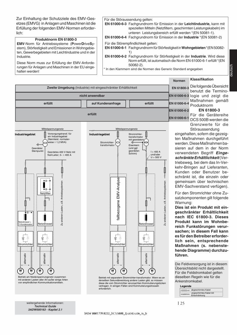
Klassifikation
Die folgende Übersichtbenutzt die Termino-logie und zeigt dieMaßnahmen gemäßProduktnorm
EN 61800-3Für die GerätereiheDCS 500B werden dieGrenzwerte für dieStöraussendung
Zur Einhaltung der Schutzziele des EMV-Ges-etzes (EMVG) in Anlagen und Maschinen ist dieErfüllung der folgenden EMV-Normen erforder-lich:
Produktnorm EN 61800-3EMV-Norm für Antriebssysteme (PowerDriveSy-stem), Störfestigkeit und Emissionen in Wohngebie-ten, Gewerbegebieten mit Leichtindustrie und in derIndustrie.
Diese Norm muss zur Erfüllung der EMV-Anforde-rungen für Anlagen und Maschinen in der EU einge-halten werden!
eingehalten, sofern die gezeig-ten Maßnahmen durchgeführtwerden. Diese Maßnahmen ba-sieren auf dem in der Normverwendeten Begriff Einge-schränkte Erhältlichkeit (Ver-triebsweg, bei dem das In-Ver-kehr-Bringen auf Lieferanten,Kunden oder Benutzer be-schränkt ist, die einzeln odergemeinsam über technischenEMV-Sachverstand verfügen).
Für den Stromrichter ohne Zu-satzkomponenten gilt folgendeWarnung:Dies ist ein Produkt mit ein-geschränkter Erhältlichkeitnach IEC 61800-3. DiesesProdukt kann im Wohnbe-reich Funkstörungen verur-sachen; in diesem Fall kannes für den Betreiber erforder-lich sein, entsprechendeMaßnahmen (s. nebenste-hende Diagramme) durchzu-führen.
Die Feldversorgung ist in diesemÜbersichtsbild nicht dargestellt.Für die Feldstromkabel geltendieselben Regeln wie für dieAnkerstromkabel.
Legende
ungeschirmtes Kabel mit Einschränkung
abgeschirmtes Kabel
weitergehende Informationen:Technical Guide
3ADW000163 - Kapitel 2.1
MMMM
Netzdrossel
Netzfilter
Stromrichter
Versorgungstransf. für ein Industriegebiet (Nennleist. normaler-weise ≤ 1,2 MVA)
Geerdeter Sternpunkt Geerdetes 400 V-Netz mit
Null-Leiter; 3~ ≤ 400 A
Stromrichter
Mittelspannungsnetz
Zu
and
ere
n L
aste
n, z
.B. A
ntrie
bssy
ste
me
n
Netzdrossel + Y-Kondensator
Industriegebiet
Betrieb am Niederspannungsnetz zusammen mit anderen Lasten aller Art außer einige Arten von empfindlichen Kommunikationsmitteln.
alte
rnat
iv
alte
rnat
iv
MMMM
Stromrichter-transformator
fallb
ezog
ene
EM
V-A
naly
se
Mittelspannungsnetz
Industriegebiet
alte
rnat
iv
Stromrichter
Stromrichter-transformatormit geerdetem
Eisenkern(und ggf. geerdeten Schirm)
Netzdrossel
alte
rnat
iv
Stromrichter
I > 400 A und/oder U > 500 V
Zu
and
eren
Las
ten,
z.B
. Ant
riebs
syst
em
en
Betrieb mit separatem Stromrichter-transformator. Wenn es an derselben Sekundärwicklung andere Lasten gibt, so müssen diese die vom Stromrichter verursachten Kommutierungslücken vertragen. In einigen Fällen sind Kommutierungsdrosseln erforderlich.
Für die Störaussendung gelten:EN 61000-6-3 Fachgrundnorm für Emission in der Leichtindustrie, kann mit
speziellen Mitteln (Netzfiltern, geschirmten Leistungskabeln) imunteren Leistungsbereich erfüllt werden *(EN 50081-1).
EN 61000-6-4 Fachgrundnorm für Emission in der Industrie *(EN 50081-2)
Für die Störempfindlichkeit gelten:EN 61000-6-1 Fachgrundnorm für Störfestigkeit in Wohngebieten *(EN 50082-
1)EN 61000-6-2 Fachgrundnorm für Störfestigkeit in der Industrie. Wird diese
Norm erfüllt, ist automatisch die Norm EN 61000-6-1 erfüllt *(EN50082-2).
* In den Klammern sind die Normen des Generic Standard angegeben
EN 61800-3
EN 61000-6-3
EN 61000-6-4
EN 61000-6-2
EN 61000-6-1
erfüllt
erfüllt
Zweite Umgebung (Industrie) mit eingeschränkter Erhältlichkeit
auf Kundenanfrage erfüllt
nicht anwendbar
Normen
I 26
4 Standard-Funktionsbelegung der Klemmen
Anschlussklemmen der SDCS-CON-2 Karte
(Digitale und analoge Ein- und Ausgänge der SDCS-CON-2)
Auf- Ein-/Ausg.- Skalie- Leistung Gleich- Bemerkungenlösung werte rung takt-
[bit] Hardware durch bereich
±90...270 V12 + Vorz. ±30...90 V R 2716/ ±20 V ➀ ➁ ➂ ➃
±8...30 V Software
12 + Vorz. -10...0...+10 V Software ±20 V ➀ ➁ ➂
11 + Vorz. -10...0...+10 V Software ±40 V ➀ ➁ ➂
11 + Vorz. -10...0...+10 V Software ±40 V ➀ ➁ ➂
11 + Vorz. -10...0...+10 V Software ±40 V ➀ ➁ ➂
≤5 * mA Ext. Anschluss≤5 * mA z.B. Sollwertpotentiom.
11 + Vorz. -10...0...+10 V Software ≤5 * mA11 + Vorz. -10...0...+10 V Software ≤5 * mAanalog ±3 V fest ≤5 * mA 3 V = Stromr.-Nennstr.
Impulsgeber-Einspeisung Bemerkungen
Eingänge nicht galvanisch getrenntImpedanz = 120 Ωmax. Eingangsfrequenz ≤300 kHz
Fühlerleitungen f. 0V (GND) u.Versorgungsspan-nung d. Geber z. Korrektur v. Spannungsabfällena.d. Leitungen (nur f. Geber 5 V/12V Vers.Spg.)
5V/ ≤0,25 A * Wählbar auf der POW-1-Karte12V/24V ≤0.2 mA *
Eingabewert Signal definiert durch Bemerkungen Software
0...8 V = "0" Signal16...60 V = "1" Signal
s. auch SystembeschreibungKapitel 2
Ausgabewert Signal definiert durch BemerkungenSoftware
s. auch SystembeschreibungKapitel 2
50 * mA Gesamtbelastbarkeit aller
7 Ausgänge = 160 mAKeine Spannungen von außenan die Ausgänge anlegen!
➀ Gesamtglättungszeitkonstante ≤2 ms➁ -20...0...+20 mA, wenn extern ein 500-Ω-Widerstand angeschlossen ist➂ 4...20 mA mit ➁ + Software-Funktion➃ Stecker S4:1-2 und 3-4 entfernen, wenn SDCS-IOB-3 eingesetzt wird* kurzschlussfest (aber ein Kurzschluss kann Fehlfunktion d. Antriebs auslösen!)
Die Schraubsteckklemmen X3: ... X7: und X16: sind abnehmbar.Beim Aufstecken der Klemmen auf die CON-2 Karte auf der linkenSeite beginnen und sicherstellen, dass die Klemmenblöcke in derrichtigen Reihenfolge ohne Zwischenraum montiert werden.
X2:
X1:
AITAC
90-270 V
30-90 V
8-30 V
+24V
AI4
ChA +ChA -
ChB +ChB -ChZ +ChZ -GND
0 V
R2716
+10V
S1:23-24
100µ
+48 V/ ≤50 mA
100k1n1n
100n
100k
100k 100k
Power-Source
Sense GNDSense Power +
0V
AI2
AI3
AI1-
+
-
+
-
+
-
-
-
+
AO1AO2
+/- I-act
47.5100µ
100n
0V (AOx)
+10V0V
-10V
DI1
DI2DI3
DI4DI5DI6
DI7DI8
47.5k220n10k
4.75k
DO4DO5
DO7
DO1
DO2DO3
DO6
22 K
345
87
67
9
X6:1 2 3
4 5 6
7 8
10
4 5
7
1 2 3
6
4
23
65
910
89
10
2
45
7
23
6
89
10
8
X3:1
X4:1
X5:1
X7:
SDCS-CON-2 Software
+24V 7 8 910 11 12
+24V 13141516 17 18
+24V4 5 6S1:
1 2 3S1:
GND
1 2
3 456
S4
Drehzahlsollwert
Tacho
Drehmomentsollwert
unbenutzt
unbenutzt
DrehzahlistwertAnkerspannung
DI1 - GerätelüfterDI2 - MotorlüfterDI3 - HauptschützDI4 - FREIDI5 - NotausDI6 - ResetDI7 - Ein/AusDI8 - Start/Stop
DO1 - Schütz-GerätelüfterDO2 - FeldschützDO3 - HauptschützDO4 - BetriebsbereitDO5 - BetriebDO6 - FREIDO7 - Frei
entnommen aus/weitergehende Informationen:Technische Daten
3ADW000165 - Kapitel 3
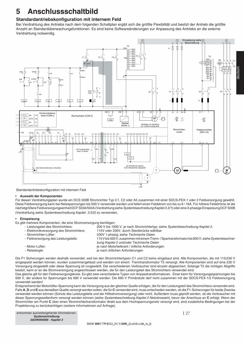
I 27
deut
sch
5 Anschlussschaltbild
Standardantriebskonfiguration mit internem Feld
Standardantriebskonfiguration mit internem FeldBei Verdrahtung des Antriebs nach dem folgenden Schaltplan ergibt sich die größte Flexibilität und besitzt der Antrieb die größteAnzahl an Standardüberwachungsfunktionen. Es sind keine Softwareänderungen zur Anpassung des Antriebs an die externeVerdrahtung notwendig.
• Auswahl der KomponentenFür diesen Verdrahtungsplan wurde ein DCS 500B Stromrichter Typ C1, C2 oder A5 zusammen mit einer SDCS-FEX-1 oder 2 Feldversorgung gewählt.Diese Feldversorgung kann bei Netzspannungen bis 500 V verwendet werden und liefert einen Feldstrom von bis zu 6 / 16A. Für höhere Feldströme ist dienächstgrößere Feldversorgungseinheit DCF 503A/504A (Verdrahtung siehe Systembeschreibung Kapitel 3.3/1) oder eine 3-phasige Einspeisung DCF 500B(Verdrahtung siehe Systembeschreibung Kapitel 3.5/2) zu verwenden.
• EinspeisungEs gibt mehrere Komponenten, die eine Stromversorgung benötigen:
- Leistungsteil des Stromrichters: 200 V bis 1000 V, je nach Stromrichtertyp; siehe Systembeschreibung Kapitel 2.- Elektronikversorgung des Stromrichters: 115V oder 230V, durch Steckbrücke wählbar- Stromrichter-Lüfter: 230V 1-phasig; siehe Technische Daten- Feldversorgung des Leistungsteils: 115 V bis 500 V; zusammen mit einem Trenn- / Spartransformator bis 600 V; siehe Systembeschrei-
bung Kapitel 2 und/oder Technische Daten- Motor-Lüfter: je nach Motorlieferant / örtliche Anforderungen- Relaislogik: je nach örtlichen Anforderungen
Die F1 Sicherungen werden deshalb verwendet, weil bei den Stromrichtertypen C1 und C2 keine eingebaut sind. Alle Komponenten, die mit 115/230 Veingespeist werden können, wurden zusammengefasst und werden von einem Trenntransformator T2 versorgt. Alle Komponenten sind auf eine 230 VVersorgung eingestellt oder diese Spannung ist vorgewählt. Die verschiedenen Verbraucher sind einzeln abgesichert. Solange T2 die richtigen Abgriffebesitzt, kann er an die Stromversorgung angeschlossen werden, die für den Leistungsteil des Stromrichters verwendet wird.Das gleiche gilt für den Feldversorgungskreis. Es gibt zwei verschiedene Typen von Anpasstransformatoren. Einer kann für Versorgungsspannungen bis500 V, der andere für Spannungen bis 690 V verwendet werden. Die 690 V Primärstufe darf nicht zusammen mit der SDCS-FEX-1/2 Feldversorgungverwendet werden!Entsprechend der Motorlüfter-Spannung kann die Versorgung aus der gleichen Quelle erfolgen, die für den Leistungsteil des Stromrichters verwendet wird.Falls A, D und E aus derselben Quelle versorgt werden sollen, die für C verwendet wird, muss entschieden werden, ob die F1-Sicherungen für beide Zweckeverwendet werden können (Schutz des Leistungsteils und der Hilfsstromversorgung) oder nicht. Außerdem muss geprüft werden, ob die Verbraucher mitdieser Spannungswellenform versorgt werden können (siehe Systembeschreibung Kapitel 2 Netzdrosseln), bevor der Anschluss an C erfolgt. Wenn derStromrichter am Punkt C über einen Stromrichtertransformator direkt aus dem Hochspannungsnetz versorgt wird, sind zusätzliche Bedingungen bei derProjektierung zu berücksichtigen (weitere Informationen auf Anfrage).
IN3
OUT3
IN1
OUT1
V5
V6
V1
V2
X96:
DO8
1 2 X99: 1 2 X2: 4 5 X2: 1 2 3 U1 W1V1 PE
K1 F6
K20
K21K20 K3 K1
X96:1
X96:2
L1 L2 L3
F1
F3
K31 3
2 4
M~
T3F23
4
1
2
T2690V660V600V575V525V500V450V415V400V380V
115V
230V
K15
K15
S1
1
2
K6 K8
X2:4
X2:5
K11K10
K21
500V460V415V400V
365V350V265V250V90V60V30V
X33
C 1 D 1
AITAC AI1 AI2 AI3 AI4+10V -10V AO1 AO2 IACT DI1 DI2 DI3 DI4 DI5 DI6 DI7 DI8 +48V DO1 DO2 DO3 DO4 DO5 DO6 DO7_ _ _ _ _+ + + + +
T
T M
0V0V0V0V0V
X3: 1 2 3 4 5 6 7 8 9 10 X4: 1 2 3 4 5 6 7 8 9 10 X6: 1 2 3 4 5 6 7 8 9 10 X7: 1 2 3 4 5 6 7 8 1...10X5:+ _
+
_
K1
K20
K21
K6
K8
1
2S1
K11
K10
S4
5 6
2 4 6
1 3 5K6
F51
2F8
1
2F7
1
2
2
1
4
3
6
5F6
I > I > I >
13
14
UV
WM3~
K11 3 5
2 4 6
L1
1
2
3
4K8
13
14
X1: 1 7
L3
X1: 5 3+ _
L1 N L1 N L1 L2 L3A C D E
Kommunikations-karte (COM-x) Rechnerkarte (CON-2)
Netzteil(POW-1)
Stromrichter-modul
EIN
AUS STOP
START
NOT-AUS
Feldstromrichter(FEX-1/2)
abhängig vom Gerätetypevtl. andere Konfiguration
die Polarität der Signaleist für Motorbetrieb dargestelltfalls Zwischenklemmen vorhanden
Einspeisung sieheBeschreibung
z.B. Druckschalter beim C4 Modul
entnommen aus/weitergehende Informationen:Systemschreibung
3ADW000066 - Kapitel 3
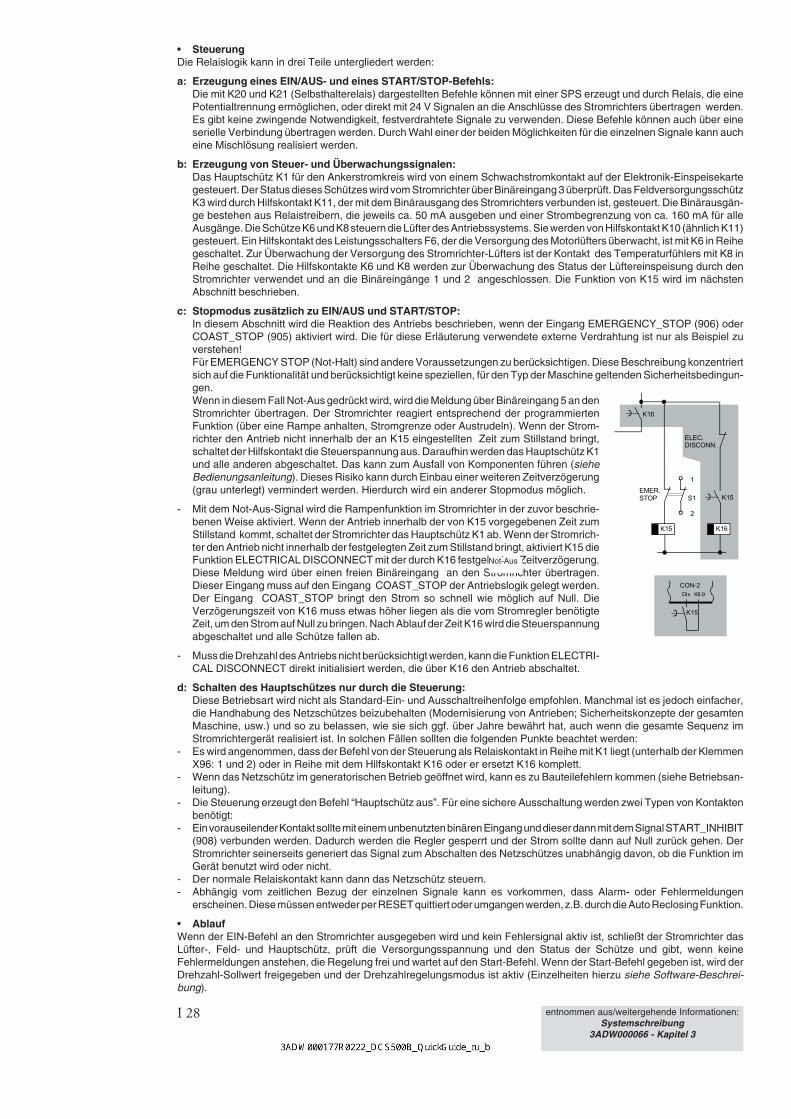
I 28 entnommen aus/weitergehende Informationen:Systemschreibung
3ADW000066 - Kapitel 3
• SteuerungDie Relaislogik kann in drei Teile untergliedert werden:
a: Erzeugung eines EIN/AUS- und eines START/STOP-Befehls:Die mit K20 und K21 (Selbsthalterelais) dargestellten Befehle können mit einer SPS erzeugt und durch Relais, die einePotentialtrennung ermöglichen, oder direkt mit 24 V Signalen an die Anschlüsse des Stromrichters übertragen werden.Es gibt keine zwingende Notwendigkeit, festverdrahtete Signale zu verwenden. Diese Befehle können auch über eineserielle Verbindung übertragen werden. Durch Wahl einer der beiden Möglichkeiten für die einzelnen Signale kann aucheine Mischlösung realisiert werden.
b: Erzeugung von Steuer- und Überwachungssignalen:Das Hauptschütz K1 für den Ankerstromkreis wird von einem Schwachstromkontakt auf der Elektronik-Einspeisekartegesteuert. Der Status dieses Schützes wird vom Stromrichter über Binäreingang 3 überprüft. Das FeldversorgungsschützK3 wird durch Hilfskontakt K11, der mit dem Binärausgang des Stromrichters verbunden ist, gesteuert. Die Binärausgän-ge bestehen aus Relaistreibern, die jeweils ca. 50 mA ausgeben und einer Strombegrenzung von ca. 160 mA für alleAusgänge. Die Schütze K6 und K8 steuern die Lüfter des Antriebssystems. Sie werden von Hilfskontakt K10 (ähnlich K11)gesteuert. Ein Hilfskontakt des Leistungsschalters F6, der die Versorgung des Motorlüfters überwacht, ist mit K6 in Reihegeschaltet. Zur Überwachung der Versorgung des Stromrichter-Lüfters ist der Kontakt des Temperaturfühlers mit K8 inReihe geschaltet. Die Hilfskontakte K6 und K8 werden zur Überwachung des Status der Lüftereinspeisung durch denStromrichter verwendet und an die Binäreingänge 1 und 2 angeschlossen. Die Funktion von K15 wird im nächstenAbschnitt beschrieben.
c: Stopmodus zusätzlich zu EIN/AUS und START/STOP:In diesem Abschnitt wird die Reaktion des Antriebs beschrieben, wenn der Eingang EMERGENCY_STOP (906) oderCOAST_STOP (905) aktiviert wird. Die für diese Erläuterung verwendete externe Verdrahtung ist nur als Beispiel zuverstehen!Für EMERGENCY STOP (Not-Halt) sind andere Voraussetzungen zu berücksichtigen. Diese Beschreibung konzentriertsich auf die Funktionalität und berücksichtigt keine speziellen, für den Typ der Maschine geltenden Sicherheitsbedingun-gen.Wenn in diesem Fall Not-Aus gedrückt wird, wird die Meldung über Binäreingang 5 an denStromrichter übertragen. Der Stromrichter reagiert entsprechend der programmiertenFunktion (über eine Rampe anhalten, Stromgrenze oder Austrudeln). Wenn der Strom-richter den Antrieb nicht innerhalb der an K15 eingestellten Zeit zum Stillstand bringt,schaltet der Hilfskontakt die Steuerspannung aus. Daraufhin werden das Hauptschütz K1und alle anderen abgeschaltet. Das kann zum Ausfall von Komponenten führen (sieheBedienungsanleitung). Dieses Risiko kann durch Einbau einer weiteren Zeitverzögerung(grau unterlegt) vermindert werden. Hierdurch wird ein anderer Stopmodus möglich.
- Mit dem Not-Aus-Signal wird die Rampenfunktion im Stromrichter in der zuvor beschrie-benen Weise aktiviert. Wenn der Antrieb innerhalb der von K15 vorgegebenen Zeit zumStillstand kommt, schaltet der Stromrichter das Hauptschütz K1 ab. Wenn der Stromrich-ter den Antrieb nicht innerhalb der festgelegten Zeit zum Stillstand bringt, aktiviert K15 dieFunktion ELECTRICAL DISCONNECT mit der durch K16 festgelegten Zeitverzögerung.Diese Meldung wird über einen freien Binäreingang an den Stromrichter übertragen.Dieser Eingang muss auf den Eingang COAST_STOP der Antriebslogik gelegt werden.Der Eingang COAST_STOP bringt den Strom so schnell wie möglich auf Null. DieVerzögerungszeit von K16 muss etwas höher liegen als die vom Stromregler benötigteZeit, um den Strom auf Null zu bringen. Nach Ablauf der Zeit K16 wird die Steuerspannungabgeschaltet und alle Schütze fallen ab.
- Muss die Drehzahl des Antriebs nicht berücksichtigt werden, kann die Funktion ELECTRI-CAL DISCONNECT direkt initialisiert werden, die über K16 den Antrieb abschaltet.
d: Schalten des Hauptschützes nur durch die Steuerung:Diese Betriebsart wird nicht als Standard-Ein- und Ausschaltreihenfolge empfohlen. Manchmal ist es jedoch einfacher,die Handhabung des Netzschützes beizubehalten (Modernisierung von Antrieben; Sicherheitskonzepte der gesamtenMaschine, usw.) und so zu belassen, wie sie sich ggf. über Jahre bewährt hat, auch wenn die gesamte Sequenz imStromrichtergerät realisiert ist. In solchen Fällen sollten die folgenden Punkte beachtet werden:
- Es wird angenommen, dass der Befehl von der Steuerung als Relaiskontakt in Reihe mit K1 liegt (unterhalb der KlemmenX96: 1 und 2) oder in Reihe mit dem Hilfskontakt K16 oder er ersetzt K16 komplett.
- Wenn das Netzschütz im generatorischen Betrieb geöffnet wird, kann es zu Bauteilefehlern kommen (siehe Betriebsan-leitung).
- Die Steuerung erzeugt den Befehl “Hauptschütz aus”. Für eine sichere Ausschaltung werden zwei Typen von Kontaktenbenötigt:
- Ein vorauseilender Kontakt sollte mit einem unbenutzten binären Eingang und dieser dann mit dem Signal START_INHIBIT(908) verbunden werden. Dadurch werden die Regler gesperrt und der Strom sollte dann auf Null zurück gehen. DerStromrichter seinerseits generiert das Signal zum Abschalten des Netzschützes unabhängig davon, ob die Funktion imGerät benutzt wird oder nicht.
- Der normale Relaiskontakt kann dann das Netzschütz steuern.- Abhängig vom zeitlichen Bezug der einzelnen Signale kann es vorkommen, dass Alarm- oder Fehlermeldungen
erscheinen. Diese müssen entweder per RESET quittiert oder umgangen werden, z.B. durch die Auto Reclosing Funktion.
• AblaufWenn der EIN-Befehl an den Stromrichter ausgegeben wird und kein Fehlersignal aktiv ist, schließt der Stromrichter dasLüfter-, Feld- und Hauptschütz, prüft die Versorgungsspannung und den Status der Schütze und gibt, wenn keineFehlermeldungen anstehen, die Regelung frei und wartet auf den Start-Befehl. Wenn der Start-Befehl gegeben ist, wird derDrehzahl-Sollwert freigegeben und der Drehzahlregelungsmodus ist aktiv (Einzelheiten hierzu siehe Software-Beschrei-bung).
EMER.STOP
K16
K15 K16
K15
ELEC.DISCONN.
DIx
K15
X6:9CON-2
S1
1
2
Not-Aus
I 29
deut
sch
1. AllgemeinWährend des Betriebes können Antriebsstromrichter ihrerSchutzart entsprechend spannungsführende, blanke, gegebe-nenfalls auch bewegliche oder rotierende Teile, sowie heißeOberflächen besitzen.
Bei unzulässigem Entfernen der erforderlichen Abdeckung, beiunsachgemäßem Einsatz, bei falscher Installation oder Bedie-nung, besteht die Gefahr von schweren Personen- oder Sach-schäden.
Weitere Informationen sind der Dokumentation zu entnehmen.
Alle Arbeiten zum Transport, zur Installation und Inbetriebnahmesowie zur Instandhaltung sind von qualifiziertem Fachpersonalauszuführen (IEC 364 bzw. CENELEC HD 384 oder DIN VDE0100 und IEC 664 oder DIN VDE 0110 und nationale Unfall-verhütungsvorschriften beachten).
Qualifiziertes Fachpersonal im Sinne dieser grundsätzlichenSicherheitshinweise sind Personen, die mit Aufstellung, Montage,Inbetriebsetzung und Betrieb des Produktes vertraut sind undüber die ihrer Tätigkeit entsprechenden Qualifikationen verfügen.
2. Bestimmungsgemäße VerwendungAntriebsstromrichter sind Komponenten, die zum Einbau inelektrische Anlagen oder Maschinen bestimmt sind.
Bei Einbau in Maschinen ist die Inbetriebnahme der An-triebsstromrichter (d.h. die Aufnahme des bestimmungsgemäßenBetriebes) solange untersagt, bis festgestellt wurde, dass dieMaschine den Bestimmungen der EG-Richtlinie 89/392/EWG(Maschinenrichtlinie) entspricht; EN 60204 ist zu beachten.
Die Inbetriebnahme (d.h. die Aufnahme des bestimmungsge-mäßen Betriebes) ist nur bei Einhaltung der EMV-Richtlinie (89/336/EWG) erlaubt.
Die Antriebsstromrichter erfüllen die Anforderungen derNiederspannungsrichtlinie 73/23/EWG. Die harmonisiertenNormen der Reihe prEN 50178/DIN VDE 0160 in Verbindung mitEN 60439-1/ VDE 0660 Teil 500 und EN 60146/ VDE 0558werden für die Antriebsstromrichter angewendet.
Die technischen Daten sowie die Angaben zu Anschlussbe-dingungen sind dem Leistungsschild und der Dokumentation zuentnehmen und unbedingt einzuhalten.
3. Transport, EinlagerungDie Hinweise für Transport, Lagerung und sachgemäße Handha-bung sind zu beachten.
Klimatische Bedingungen sind entsprechend prEN 50178einzuhalten.
4. AufstellungDie Aufstellung und Kühlung der Geräte muss entsprechend denVorschriften der zugehörigen Dokumentation erfolgen.
Die Antriebsstromrichter sind vor unzulässiger Beanspruchung zuschützen. Insbesondere dürfen bei Transport und Handhabungkeine Bauelemente verbogen und/oder Isolationsabständeverändert werden. Die Berührung elektronischer Bauelementeund Kontakte ist zu vermeiden.
Antriebsstromrichter enthalten elektrostatisch gefährdete Bauele-mente, die leicht durch unsachgemäße Behandlung beschädigtwerden können. Elektrische Komponenten dürfen nicht mecha-nisch beschädigt oder zerstört werden (unter UmständenGesundheitsgefährdung!).
5. Elektrischer AnschlussBei Arbeiten an unter Spannung stehenden Antriebsstromrichternsind die geltenden nationalen Unfallverhütungsvorschriften (z.B.VBG 4) zu beachten.
Die elektrische Installation ist nach den einschlägigen Vor-schriften durchzuführen (z.B. Leitungsquerschnitte, Absiche-rungen, Schutzleiteranbindung). Darüberhinausgehende Hin-weise sind in der Dokumentation enthalten.
Hinweise für die EMV-gerechte Installation - wie Schirmung,Erdung, Anordnung von Filtern und Verlegung der Leitungen -befinden sich in der Dokumentation der Antriebsstromrichter.Diese Hinweise sind auch bei CE-gekennzeichneten Antriebs-stromrichtern stets zu beachten. Die Einhaltung der durch dieEMV-Gesetzgebung geforderten Grenzwerte liegt in der Verant-wortung des Herstellers der Anlage oder Maschine.
6. BetriebAnlagen, in die Antriebsstromrichter eingebaut sind, müssen ggf.mit zusätzlichen Überwachungs- und Schutzeinrichtungen gemäßden jeweils gültigen Sicherheitsbestimmungen, z.B. Gesetz übertechnische Arbeitsmittel, Unfallverhütungsvorschriften usw.ausgerüstet werden. Veränderungen der Antriebsstromrichter mitder Bediensoftware sind gestattet.
Nach dem Trennen der Antriebsstromrichter von der Versor-gungsspannung dürfen spannungsführende Geräteteile undLeistungsanschlüsse wegen möglicherweise aufgeladenerKondensatoren nicht sofort berührt werden. Hierzu sind dieentsprechenden Hinweisschilder auf dem Antriebsstromrichter zubeachten.
Während des Betriebes sind alle Abdeckungen und Türengeschlossen zu halten.
7. Wartung und InstandhaltungDie Dokumentation des Herstellers ist zu beachten.
Diese Sicherheitshinweise sind aufzubewahren!
6 Sicherheits- und Anwendungshinweise
für Antriebsstromrichter DCS / DCF / DCR
(gemäß: Niederspannungsrichtlinie 73/23/EWG)
entnommen aus/weitergehende Informationen:Sicherheitshinweise
3ADW000033
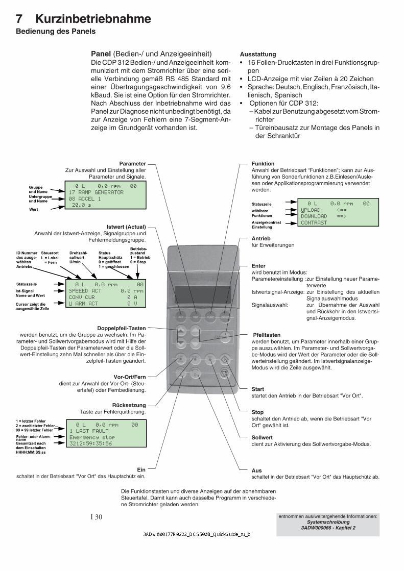
I 30
Panel (Bedien-/ und Anzeigeeinheit)Die CDP 312 Bedien-/ und Anzeigeeinheit kom-muniziert mit dem Stromrichter über eine seri-elle Verbindung gemäß RS 485 Standard miteiner Übertragungsgeschwindigkeit von 9,6kBaud. Sie ist eine Option für den Stromrichter.Nach Abschluss der Inbetriebnahme wird dasPanel zur Diagnose nicht unbedingt benötigt, dazur Anzeige von Fehlern eine 7-Segment-An-zeige im Grundgerät vorhanden ist.
Die Funktionstasten und diverse Anzeigen auf der abnehmbarenSteuertafel. Damit kann auch dasselbe Programm in verschiede-ne Stromrichter geladen werden.
Istwert (Actual)Anwahl der Istwert-Anzeige, Signalgruppe und
Fehlermeldungsgruppe.
ParameterZur Auswahl und Einstellung aller
Parameter und Signale.
FunktionAnwahl der Betriebsart “Funktionen”; kann zur Aus-führung von Sonderfunktionen z.B.Einlesen/Ausle-sen oder Applikationsprogrammierung verwendetwerden.
Antriebfür Erweiterungen
Doppelpfeil-Tastenwerden benutzt, um die Gruppe zu wechseln. Im Pa-
rameter- und Sollwertvorgabemodus wird mit Hilfe derDoppelpfeil-Tasten der Parameterwert oder die Soll-wert-Einstellung zehn Mal schneller als über die Ein-
zelpfeil-Tasten geändert.
Pfeiltastenwerden benutzt, um Parameter innerhalb einer Grup-pe auszuwählen. Im Parameter- und Sollwertvorga-be-Modus wird der Wert der Parameter oder die Soll-werteinstellung geändert. Im Istwertsignalanzeige-Modus wird die Zeile ausgewählt.
Enterwird benutzt im Modus:Parametereinstellung :zur Einstellung neuer Parame-
terwerteIstwertsignal-Anzeige: zur Einstellung des aktuellen
SignalauswahlmodusSignalauswahl: zur Übernahme der Auswahl
und Rückkehr in den Istwertsi-gnal-Anzeigemodus.
Vor-Ort/Ferndient zur Anwahl der Vor-Ort- (Steu-
ertafel) oder Fernbedienung.
RücksetzungTaste zur Fehlerquittierung.
Sollwertdient zur Aktivierung des Sollwertvorgabe-Modus.
Startstartet den Antrieb in der Betriebsart "Vor Ort".
Stopschaltet den Antrieb ab, wenn die Betriebsart "VorOrt" gewählt ist.
Einschaltet in der Betriebsart "Vor Ort" das Hauptschütz ein.
Ausschaltet in der Betriebsart "Vor Ort" das Hauptschütz ab.
Ausstattung• 16 Folien-Drucktasten in drei Funktionsgrup-
pen• LCD-Anzeige mit vier Zeilen à 20 Zeichen• Sprache: Deutsch, Englisch, Französisch, Ita-
lienisch, Spanisch• Optionen für CDP 312:
– Kabel zur Benutzung abgesetzt vom Strom-richter
– Türeinbausatz zur Montage des Panels inder Schranktür
0 L 0,0 rpm 001 LAST FAULTEmergency stop3212:59:35:56
1 = letzter Fehler2 = zweitletzter Fehler...99 = 99 letzter Fehler
Gesamtzeit nach dem EinschaltenHHHH:MM:SS.ss
Fehler- oder Alarm-name
StatuszeilewählbareFunktionenAnzeigekontrastEinstellung
0 L 0,0 rpm 00UPLOAD <==DOWNLOAD ==>CONTRAST
ID Nummer des ausge- wähltenAntriebs
SteuerortL = Lokal = Fern
StatusHauptschütz0 = geöffnet1 = geschlossen
Drehzahl-sollwertU/min
Betriebs-
1 = Betrieb0 = Stop
StatuszeileIst-SignalName und Wert
Cursor zeigt dieausgewählte Zeile
0 L 0,0 rpm 00SPEEED ACT 0,0 rpmCONV CUR 0 AU ARM ACT 0 V
zustand
0 L 0,0 rpm 00 17 RAMP GENERATOR08 ACCEL 1 20.0 s
Gruppeund NameUntergruppeund Name
Wert
entnommen aus/weitergehende Informationen:Systemschreibung
3ADW000066 - Kapitel 2
7 KurzinbetriebnahmeBedienung des Panels
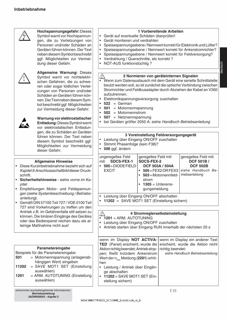
I 31
deut
sch
Inbetriebnahme
Hochspannungsgefahr: DiesesSymbol warnt vor Hochspannun-gen, die zu Verletzungen vonPersonen und/oder Schäden anGeräten führen können. Der Textneben diesem Symbol beschreibtggf. Möglichkeiten zur Vermei-dung dieser Gefahr.
Allgemeine Warnung: DiesesSymbol warnt vor nichtelektri-schen Gefahren, die zu schwe-ren oder sogar tödlichen Verlet-zungen von Personen und/oderSchäden an Geräten führen kön-nen. Der Text neben diesem Sym-bol beschreibt ggf. Möglichkeitenzur Vermeidung dieser Gefahr.
Warnung vor elektrostatischerEntladung: Dieses Symbol warntvor elektrostatischen Entladun-gen, die zu Schäden an Gerätenführen können. Der Text nebendiesem Symbol beschreibt ggf.Möglichkeiten zur Vermeidungdieser Gefahr.
1 Vorbereitende Arbeiten• Gerät auf eventuelle Schäden überprüfen!• Gerät montieren und verdrahten• Speisespannungsebene / Nennwert korrekt für Elektronik und Lüfter?• Speisespannungsebene / Nennwert korrekt für Ankerstromrichter?• Speisespannungsebene / Nennwert korrekt für Feldversorgung?• Verdrahtung / Querschnitte, etc korrekt ?• NOT-AUS funktionstüchtig ?
2 Normieren von geräteinternen Signalen• Wenn zum Datenaustausch mit dem Gerät eine serielle Schnittstelle
beutzt werden soll, so ist zunächst die optische Verbindung zwischenStromrichter und Feldbusadapter durch Abziehen der Kabel an V260aufzutrennen.
• Elektronikspannungsversorgung zuschalten• 522 = German• 501 = Motornennspannung• 502 = Motornennstrom• 507 = Netznennspannung• bei Geräten größer 2050 A: siehe Handbuch Betriebsanleitung
3 Voreinstellung Feldversorgungsgerät• Leistung über Eingang ON/OFF zuschalten• Stimmt Phasenfolge (kein F38)?• 506 ggf. ändern
ungeregeltes Feldmit: SDCS-FEX-1• 505 = DIODE FIELD
EXCIT
geregeltes Feld mit:SDCS-FEX-2
DCF 503A / 504A• 505 = FEX2 OR FEX3• 503 = Motornennfeld-
strom• 1305 = Untererre-
gungsmeldung
geregeltes Feld mit:DCF 501B /DCF 502B
siehe Handbuch Be-triebsanleitung
• Leistung über Eingang ON/OFF abschalten• 11202 = SAVE MOT1 SET (Einstellung sichern)
4 Stromreglerselbsteinstellung• 1201 = ARM. AUTOTUNING• Leistung über Eingang ON/OFF zuschalten• Antrieb starten über Eingang RUN innerhalb der nächsten 20 s
wenn im Display NOT ACTIVA-TED (Panel) erscheint, wurde dieAktion richtig beendet; Antrieb stop-pen; fließt trotzdem AnkerstromWert der n
min Meldung (2201) erhö-
hen• Leistung / Antrieb über Eingän-
ge abschalten• 11202 = SAVE MOT1 SET (Ein-
stellung sichern)
wenn im Display ein anderer Texterscheint, wurde die Aktion nichtrichtig beendet:
siehe Handbuch BetriebsanleitungParametereingabe
Beispiele für die Parametereingabe:501 = Motornennspannung (anlagenab-
hängigen Wert) eingeben11202 = SAVE MOT1 SET (Einstellung
auswählen)1201 = ARM. AUTOTUNING (Einstellung
auswählen)
Allgemeine Hinweise• Diese Kurzinbetriebnahme bezieht sich auf
Kapitel 6 Anschlussschaltbild dieser Druck-schrift.
• Sicherheitshinweise - siehe vorne im Ka-pitel
• Empfehlungen Motor- und Feldspannun-gen (siehe Systembeschreibung / Betriebs-anleitung).
• Gemäß DIN 57100 Teil 727 / VDE 0100 Teil727 sind Vorkehrungen zu treffen um denAntrieb z.B. im Gefahrenfalle still setzen zukönnen. Die binären Eingänge des Gerätesoder das Bedienpanel reichen dazu als al-leinige Maßnahme nicht aus!
entnommen aus/weitergehende Informationen:Betriebsanleitung
3ADW000055 - Kapitel 2
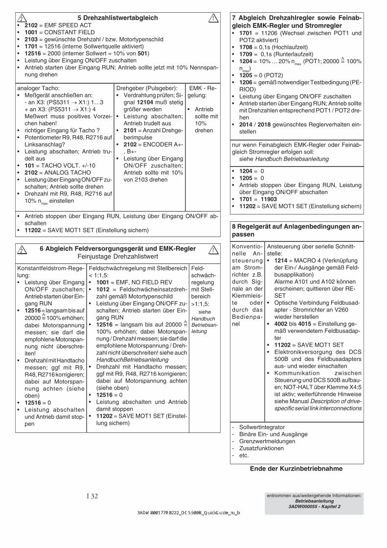
I 32 entnommen aus/weitergehende Informationen:Betriebsanleitung
3ADW000055 - Kapitel 2
5 Drehzahlistwertabgleich• 2102 = EMF SPEED ACT• 1001 = CONSTANT FIELD• 2103 = gewünschte Drehzahl / bzw. Motortypenschild• 1701 = 12516 (interne Sollwertquelle aktiviert)• 12516 = 2000 (interner Sollwert = 10% von 501)• Leistung über Eingang ON/OFF zuschalten• Antrieb starten über Eingang RUN; Antrieb sollte jetzt mit 10% Nennspan-
nung drehen
analoger Tacho:• Meßgerät anschließen an:
- an X3: (PS5311 → X1:) 1…3+ an X3: (PS5311 → X1:) 4Meßwert muss positives Vorzei-chen haben!
• richtiger Eingang für Tacho ?• Potentiometer R9, R48, R2716 auf
Linksanschlag?• Leistung abschalten; Antrieb tru-
delt aus• 101 = TACHO VOLT. +/-10• 2102 = ANALOG TACHO• Leistung über Eingang ON/OFF zu-
schalten; Antrieb sollte drehen• Drehzahl mit R9, R48, R2716 auf
10% nmax einstellen
Drehgeber (Pulsgeber):• Verdrahtung prüfen; Si-
gnal 12104 muß stetiggrößer werden
• Leistung abschalten;Antrieb trudelt aus
• 2101 = Anzahl Drehge-berimpulse
• 2102 = ENCODER A+-, B+-
• Leistung über EingangON/OFF zuschalten;Antrieb sollte mit 10%von 2103 drehen
EMK - Re-gelung:
• Antriebsollte mit10%drehen
• Antrieb stoppen über Eingang RUN, Leistung über Eingang ON/OFF ab-schalten
• 11202 = SAVE MOT1 SET (Einstellung sichern)
7 Abgleich Drehzahlregler sowie Feinab-gleich EMK-Regler und Stromregler• 1701 = 11206 (Wechsel zwischen POT1 und
POT2 aktiviert)• 1708 = 0,1s (Hochlaufzeit)• 1709 = 0,1s (Runterlaufzeit)• 1204 = 10% … 20% nmax (POT1; 20000 = 100%
nmax)• 1205 = 0 (POT2)• 1206 = gemäß notwendiger Testbedingung (PE-
RIOD)• Leistung über Eingang ON/OFF zuschalten• Antrieb starten über Eingang RUN; Antrieb sollte
mit Drehzahlen entsprechend POT1 / POT2 dre-hen
• 2014 / 2018 gewünschtes Reglerverhalten ein-stellen
nur wenn Feinabgleich EMK-Regler oder Feinab-gleich Stromregler erfolgen soll:
siehe Handbuch Betriebsanleitung
• 1204 = 0• 1205 = 0• Antrieb stoppen über Eingang RUN, Leistung
über Eingang ON/OFF abschalten• 1701 = 11903• 11202 = SAVE MOT1 SET (Einstellung sichern)
8 Regelgerät auf Anlagenbedingungen an-passen
6 Abgleich Feldversorgungsgerät und EMK-ReglerFeinjustage Drehzahlistwert
Konstantfeldstrom-Rege-lung:• Leistung über Eingang
ON/OFF zuschalten;Antrieb starten über Ein-gang RUN
• 12516 = langsam bis auf20000 = 100% erhöhen;dabei Motorspannungmessen; sie darf dieempfohlene Motorspan-nung nicht überschre-iten!
• Drehzahl mit Handtachomessen; ggf mit R9,R48, R2716 korrigieren;dabei auf Motorspan-nung achten (sieheoben)
• 12516 = 0• Leistung abschalten
und Antrieb damit stop-pen
Feldschwächregelung mit Stellbereich< 1:1,5:• 1001 = EMF, NO FIELD REV• 1012 = Feldschwächeinsatzdreh-
zahl gemäß Motortypenschild• Leistung über Eingang ON/OFF zu-
schalten; Antrieb starten über Ein-gang RUN
• 12516 = langsam bis auf 20000 =100% erhöhen; dabei Motorspan-nung / Drehzahl messen; sie darf dieempfohlene Motorspannung / Dreh-zahl nicht überschreiten! siehe auchHandbuchBetriebsanleitung
• Drehzahl mit Handtacho messen;ggf mit R9, R48, R2716 korrigieren;dabei auf Motorspannung achten(siehe oben)
• 12516 = 0• Leistung abschalten und Antrieb
damit stoppen• 11202 = SAVE MOT1 SET (Einstel-
lung sichern)
Feld-schwäch-regelungmit Stell-bereich>1:1,5:
sieheHandbuchBetriebsan-leitung
Konventio-nelle An-steuerungam Strom-richter z.B.durch Sig-nale an derKlemmleis-te oderdurch dasBedienpa-nel
Ansteuerung über serielle Schnitt-stelle:• 1214 = MACRO 4 (Verknüpfung
der Ein-/ Ausgänge gemäß Feld-busapplikation)Alarme A101 und A102 könnenerscheinen; quittieren über RE-SET
• Optische Verbindung Feldbusad-apter - Stromrichter an V260wieder herstellen
• 4002 bis 4015 = Einstellung ge-mäß verwendetem Feldbusadap-ter
• 11202 = SAVE MOT1 SET• Elektronikversorgung des DCS
500B und des Feldbusadaptersaus- und wieder einschalten
• Kommunikation zwischenSteuerung und DCS 500B aufbau-en; NOT-HALT über Klemme X4:5ist aktiv; weiterführende Hinweisesiehe Manual Description of drive-specific serial link interconnections
- Sollwertintegrator- Binäre Ein- und Ausgänge- Grenzwertmeldungen- Zusatzfunktionen- etc.
Ende der Kurzinbetriebnahme
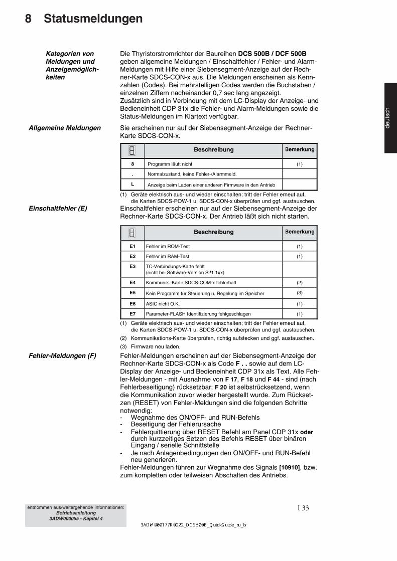
I 33
deut
sch
8 Statusmeldungen
Kategorien von Meldungen und Anzeigemöglich-keiten
Die Thyristorstromrichter der Baureihen DCS 500B / DCF 500B geben allgemeine Meldungen / Einschaltfehler / Fehler- und Alarm-Meldungen mit Hilfe einer Siebensegment-Anzeige auf der Rech-ner-Karte SDCS-CON-x aus. Die Meldungen erscheinen als Kenn-zahlen (Codes). Bei mehrstelligen Codes werden die Buchstaben / einzelnen Ziffern nacheinander 0,7 sec lang angezeigt. Zusätzlich sind in Verbindung mit dem LC-Display der Anzeige- und Bedieneinheit CDP 31x die Fehler- und Alarm-Meldungen sowie die Status-Meldungen im Klartext verfügbar.
Allgemeine Meldungen
Sie erscheinen nur auf der Siebensegment-Anzeige der Rechner-Karte SDCS-CON-x.
Beschreibung Bemerkung
8 Programm läuft nicht (1)
. Normalzustand, keine Fehler-/Alarmmeld.
L Anzeige beim Laden einer anderen Firmware in den Antrieb
(1) Geräte elektrisch aus- und wieder einschalten; tritt der Fehler erneut auf, die Karten SDCS-POW-1 u. SDCS-CON-x überprüfen und ggf. austauschen.
Einschaltfehler (E)
Einschaltfehler erscheinen nur auf der Siebensegment-Anzeige der Rechner-Karte SDCS-CON-x. Der Antrieb läßt sich nicht starten.
Beschreibung Bemerkung
E1 Fehler im ROM-Test (1)
E2 Fehler im RAM-Test (1)
E3 TC-Verbindungs-Karte fehlt (nicht bei Software-Version S21.1xx)
E4 Kommunik.-Karte SDCS-COM-x fehlerhaft (2)
E5 Kein Programm für Steuerung u. Regelung im Speicher (3)
E6 ASIC nicht O.K. (1)
E7 Parameter-FLASH Identifizierung fehlgeschlagen (1)
(1) Geräte elektrisch aus- und wieder einschalten; tritt der Fehler erneut auf, die Karten SDCS-POW-1 u. SDCS-CON-x überprüfen und ggf. austauschen.
(2) Kommunikations-Karte überprüfen, richtig aufstecken und ggf. austauschen.
(3) Firmware neu laden. Fehler-Meldungen (F)
Fehler-Meldungen erscheinen auf der Siebensegment-Anzeige der Rechner-Karte SDCS-CON-x als Code F . . sowie auf dem LC-Display der Anzeige- und Bedieneinheit CDP 31x als Text. Alle Feh-ler-Meldungen - mit Ausnahme von F 17, F 18 und F 44 - sind (nach Fehlerbeseitigung) rücksetzbar; F 20 ist selbstrücksetzend, wenn die Kommunikation zuvor wieder hergestellt wurde. Zum Rückset-zen (RESET) von Fehler-Meldungen sind die folgenden Schritte notwendig: - Wegnahme des ON/OFF- und RUN-Befehls - Beseitigung der Fehlerursache - Fehlerquittierung über RESET Befehl am Panel CDP 31x oder
durch kurzzeitiges Setzen des Befehls RESET über binären Eingang / serielle Schnittstelle
- Je nach Anlagenbedingungen den ON/OFF- und RUN-Befehl neu generieren.
Fehler-Meldungen führen zur Wegnahme des Signals [10910], bzw. zum kompletten oder teilweisen Abschalten des Antriebs.
entnommen aus/weitergehende Informationen:Betriebsanleitung
3ADW000055 - Kapitel 4
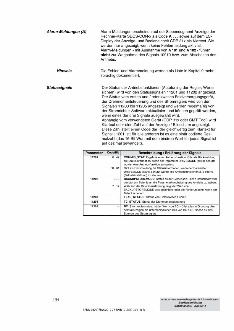
I 34
Alarm-Meldungen (A)
Alarm-Meldungen erscheinen auf der Siebensegment-Anzeige der Rechner-Karte SDCS-CON-x als Code A . . . sowie auf dem LC-Display der Anzeige- und Bedieneinheit CDP 31x als Klartext. Sie werden nur angezeigt, wenn keine Fehlermeldung aktiv ist. Alarm-Meldungen - mit Ausnahme von A 101 und A 102 - führen nicht zur Wegnahme des Signals 10910 bzw. zum Abschalten des Antriebs.
Hinweis Die Fehler- und Alarmmeldung werden als Liste in Kapitel 9 mehr-sprachig dokumentiert.
Statussignale
Der Status der Antriebsfunktionen (Autotuning der Regler; Werte sichern) wird von den Statussignalen 11201 und 11202 angezeigt. Der Status vom ersten und / oder zweiten Feldversorgungsgerät, der Drehmomentsteuerung und des Stromreglers wird von den Signalen 11203 bis 11205 angezeigt und werden regelmäßig von der Stromrichter-Software aktualisiert und können geprüft werden, wenn eines der drei Signale ausgewählt wird. Abhängig vom verwendeten Gerät (CDP 31x oder CMT Tool) wird Klartext oder eine Zahl auf der Anzeige / Bildschirm angezeigt. Diese Zahl stellt einen Code dar, der gleichwertig zum Klartext für Signal 11201 ist; für alle anderen ist es eine binär codierte Dezi-malzahl (das 16-Bit Wort mit dem binären Wert für jedes Signal ist auf dezimal gewandelt).
Parameter Code/Bit Beschreibung / Erklärung der Signale
11201 0...49 COMMIS_STAT: Ergebnis einer Antriebsfunktion. Gibt als Rückmeldung die Statusinformation, wenn der Parameter DRIVEMODE (1201) benutzt wurde, eine Antriebsfunktion zu starten.
50...61 Gibt als Rückmeldung die Statusinformation, wenn der Parameter DRIVEMODE (1201) benutzt wurde, die Antriebsfunktionen 3, 5 oder 6 (Selbsteinstellung) zu starten.
11202 0...6 BACKUPSTOREMODE: Status dieser Betriebsart. Diese Betriebsart wird benutzt um Befehle an die Parameterhandhabung des Antriebs zu geben.
7...17 Während der Befehlsausführung zeigt der Wert von BACKUPSTOREMODE was geschieht, oder die Fehlerursache, wenn der Befehl scheitert.
11203 -- FEXC_STATUS: Status von Field exciter 1 und 2
11204 -- TC_STATUS: Status der Drehmomentsteuerung
11205 -- BC: Stromreglerstatus. Ist der Wert von BC = 0 ist alles in Ordnung. An-dernfalls zeigen die unterschiedlichen Bits von BC die Ursache für das Sperren des Stromreglers.
entnommen aus/weitergehende Informationen:Betriebsanleitung
3ADW000055 - Kapitel 4
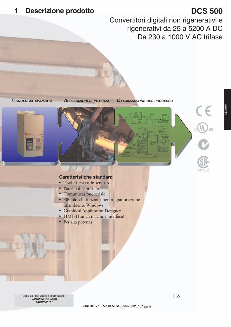
I 35
italia
no
1 Descrizione prodotto
tratto da / per ulteriori informazioni:Volantino DCS500B
3ADW000151
R
NRTL /C
DCS 500Convertitori digitali non rigenerativi e
rigenerativi da 25 a 5200 A DCDa 230 a 1000 V AC trifase
TECNOLOGIA AVANZATA APPLICAZIONI DI POTENZA OTTIMIZZAZIONE DEL PROCESSO
Caratteristiche standard• Tool di messa in servizio• Panello di controllo• Comunucazione seriale• 300 blocchi funzione per programmazione
in ambiente Windows• Graphical Application Designer• HMI (Human machine interface)• Per alta potenza
I 35
3ADW000177R0200_DCS500B_QuickGuide_edisf_b
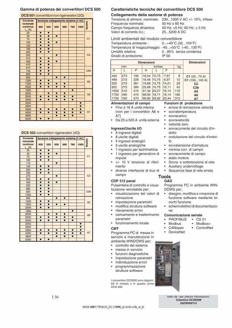
I 36 tratto da / per ulteriori informazioni:Volantino DCS500B
3ADW000151
I convertitori DCS500 sono disponi-bili in modulo o in quadro comeDCA 500.
Gamma di potenza dei convertitori DCS 500
Alimentazioni di campo• Fino a 16 A unità interna
(non per i convertitori A6 eA7)
• Da 25 a 520 A unità esterna
Ingressi/Uscite I/O• 8 ingressi digitali• 8 uscite digitali• 4 ingressi analogici• 3 uscite analogiche• 1 ingresso per tachimetrica• 1 ingresso per generatore di
impulsi• +/- 10 V tensione di riferi-
mento• diverse interfaccie di bus di
campo
Funzioni di protezione• errore di retroazione velocità• sovratemperatura• sovracarico• sovravelocità• velocità zero• sovracorrente del circuito d'in-
dotto• ondulazione del circuito d'indot-
to• sovratensione d'armatura• minima corr. di campo• sovracorrente di campo• stallo motore• Sovra- e sottotensione di rete• Auxiliary undervoltage• Sequenza fase di rete errata
CDP 312 panelPulsantiera di controllo e visua-lizzaione remotabile per:• visualizzazione del valori di
retroazione• impostazione parametri• modifica struttura software• rilevamento errori• caricamento e trasferimento
parametri• funzionamento locale
Caratteristiche tecniche del convertitore DCS 500
CMTProgramma PC di messa inservizio e manutenzione inambiente WINDOWS per:• controllo del sistema• messa in servizio• funzioni diagnostiche• impostazione parametri• individuazione errori• programmazazione
strutture software
DCS 502 convertitori rigenerativi (4Q)
DCS 501 convertitori non rigenerativi (2Q)
GADProgramma PC in ambiente WIN-DOWS per:• disegno, modifica e creazione di
funzione software mediante bl-occhi funzione
• schemi elettrici di documentazio-ne
Collegamento della sezione di potenzaTensione di aliment. nominale: 230...1000 V AC +/- 10%, trifaseFrequenza nominale: 50 Hz o 60 HzCampo frequenza dinamica: 50 Hz: ±5 Hz; 60 Hz: ± 5 HzValori di corrente d.c.: 25...5200 A DC
Limiti ambientali del modulo convertidoreTemperatura ambiente : 0...+40°C (32...104°F)Temperatura di magazzinaggio: -40...+55°C (-40...130°F)Umidità relativa: 5...95% senza condensaGrado di protezione: IP 00
Tools
Comunicazione seriale• PROFIBUS • CS 31• Modbus • Modbus+• CANopen • ControlNet• DeviceNet
tensione collegamento sistema [V AC] Corrente nominale continuo
IDC
[A]
400
500
600
690
790
1000
Mo
del
lo
25 50 75 100 125
C1
180 225 245 315 405 470
C2
610 740 900
C2b
900 1200 1500 2000
A5
1900 2050 2500 3000
A6
2050 2600 3300 4000 4800 5200
A7
tensione collegamento sistema [V AC] Corrente nominale continuo
IDC
[A]
400
500
600
690
790
1000
Mo
del
lo
25 50 75 100 110 140
C1
200 250 270 350 450 520
C2
680 820
1000
C2b
900 1200 1500 2000
A5
1900 2050 2500 3000
A6
2050 2600 3300 4000 4800 5200
A7
Dimensioni
C1 (25...75 A)C1 (100...140 A)
C2C2bA5A6A7
Dimensionimm inches kg
H L P H L P
420 273 195 16,54 10,75 7,67 8469 273 228 18,46 10,75 8,97 12505 273 361 19,88 10,75 14,21 29652 273 384 25,66 10,75 15,11 421050 510 410 41,34 20,07 16,14 1101750 460 410 68,90 18,11 16,14 1801750 760 570 68,90 29,92 22,44 315
I 37
italia
no
2 Note, brevi istruzioni CD e documentazione - Informazionigenerali
La ringraziamo per l'acquisto del convertitore dipotenza per azionamenti in c.c. ABB e per lafiducia accordata ai nostri prodotti.
Al fine di garantire la Sua completa soddisfazio-ne nei nostri prodotti, abbiamo provveduto aredigere la presente brochure, con l'intento dipresentare, in sintesi, i principali dati relativi alprodotto, alcune note sulla compatibilità elettro-magnetica, impieghi tipici, messa in servizio eguida alla risoluzione dei guasti.
Qualora desideri ulteriori informazioni sul pro-dotto in questione, oltre alla presente documen-tazione sintetica troverà un CD-ROM (che faparte integrante del presente pacchetto infor-mativo) nelle cinque lingue principali - inglese,tedesco, italiano, spagnolo e francese - e conte-nente quanto segue:
Documentazione
Documentazione sui nostri prodotti delle serie:• DCS400• DCS500• DCS600
La nostra documentazione si articola come se-gue:
Descrizione del sistemainformazioni complete sulla struttura del siste-ma del convertitore di potenza in generale.
Data tecniciinformazioni dettagliate complete di tutti i parti-colari sui singoli componenti, quali dimensionimoduli, schede elettroniche, ventilatori e com-ponenti ausiliari.
Istruzioni per l'usocon tutte le informazioni relative a messa inservizio e manutenzione dell'intero azionamen-to, in forma dettagliata.
Descrizione software e blocchetti applicativirichiesti unicamente per la programmazionedell'azionamento, disponibili solo in lingua in-glese e non in formato cartaceo.
Manuale di manutenzioneper interventi di manutenzione e riparazionesulle unità.
Inoltre, diverse informazioni sulle applicazio-ni (ad es. 12 impulsi) e accessori tecnici, ecc.
Requisiti di sistema per l'utilizzo delCD-ROM
• Sistema operativo WINDOWS 98, NT, 2000,XP
• ACROBAT READER 4.0 o superiore (si con-siglia 5.0 - contenuto nel CD-ROM)
• INTERNET Explorer 5.0 o versione successi-va
Se il CD ROM non si avvia automaticamente,fare doppio clic su START.HTM
Ulteriore supporto
Restiamo inoltre a Sua completa disposizionecon un servizio di assistenza volto a garantire lasoddisfazione del cliente - da sempre una nos-tra priorità assoluta.
InternetNella homepage di ABB all'indirizzo
www.abb.com/dc
troverete una serie di informazioni relativamen-te a• prodotti in c.c.• assistenza• ultimi aggiornamenti• strumenti• download, ecc.La invitiamo a visitare il nostro sito Web.
ContattiPer ulteriori informazioni potrà rivolgersi allasede ABB Drives locale oppure inviare una e-mail all'indirizzo:
indicando nome, società, indirizzo e numero ditelefono. Sarà nostra premura comunicarLe tem-pestivamente la persona di riferimento che po-trà contattare.
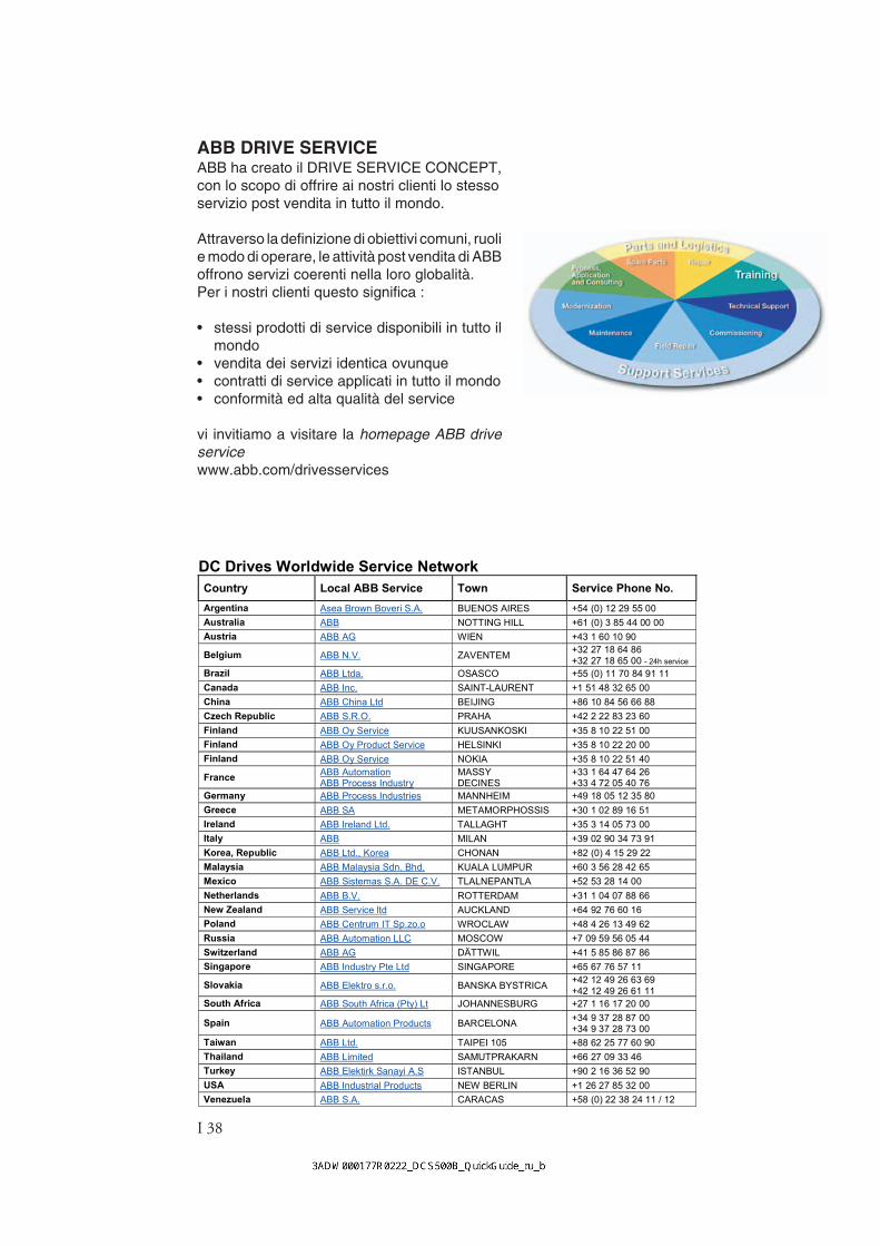
I 38
ABB DRIVE SERVICEABB ha creato il DRIVE SERVICE CONCEPT,con lo scopo di offrire ai nostri clienti lo stessoservizio post vendita in tutto il mondo.
Attraverso la definizione di obiettivi comuni, ruolie modo di operare, le attività post vendita di ABBoffrono servizi coerenti nella loro globalità.Per i nostri clienti questo significa :
• stessi prodotti di service disponibili in tutto ilmondo
• vendita dei servizi identica ovunque• contratti di service applicati in tutto il mondo• conformità ed alta qualità del service
vi invitiamo a visitare la homepage ABB driveservicewww.abb.com/drivesservices
DC Drives Worldwide Service Network Country Local ABB Service Town Service Phone No. Argentina Asea Brown Boveri S.A. BUENOS AIRES +54 (0) 12 29 55 00 Australia ABB NOTTING HILL +61 (0) 3 85 44 00 00 Austria ABB AG WIEN +43 1 60 10 90
Belgium ABB N.V. ZAVENTEM +32 27 18 64 86 +32 27 18 65 00 - 24h service
Brazil ABB Ltda. OSASCO +55 (0) 11 70 84 91 11 Canada ABB Inc. SAINT-LAURENT +1 51 48 32 65 00 China ABB China Ltd BEIJING +86 10 84 56 66 88 Czech Republic ABB S.R.O. PRAHA +42 2 22 83 23 60 Finland ABB Oy Service KUUSANKOSKI +35 8 10 22 51 00 Finland ABB Oy Product Service HELSINKI +35 8 10 22 20 00 Finland ABB Oy Service NOKIA +35 8 10 22 51 40
France ABB Automation ABB Process Industry
MASSY DECINES
+33 1 64 47 64 26 +33 4 72 05 40 76
Germany ABB Process Industries MANNHEIM +49 18 05 12 35 80 Greece ABB SA METAMORPHOSSIS +30 1 02 89 16 51 Ireland ABB Ireland Ltd. TALLAGHT +35 3 14 05 73 00 Italy ABB MILAN +39 02 90 34 73 91 Korea, Republic ABB Ltd., Korea CHONAN +82 (0) 4 15 29 22 Malaysia ABB Malaysia Sdn. Bhd. KUALA LUMPUR +60 3 56 28 42 65 Mexico ABB Sistemas S.A. DE C.V. TLALNEPANTLA +52 53 28 14 00 Netherlands ABB B.V. ROTTERDAM +31 1 04 07 88 66 New Zealand ABB Service ltd AUCKLAND +64 92 76 60 16 Poland ABB Centrum IT Sp.zo.o WROCLAW +48 4 26 13 49 62 Russia ABB Automation LLC MOSCOW +7 09 59 56 05 44 Switzerland ABB AG DÄTTWIL +41 5 85 86 87 86 Singapore ABB Industry Pte Ltd SINGAPORE +65 67 76 57 11
Slovakia ABB Elektro s.r.o. BANSKA BYSTRICA +42 12 49 26 63 69 +42 12 49 26 61 11
South Africa ABB South Africa (Pty) Lt JOHANNESBURG +27 1 16 17 20 00
Spain ABB Automation Products BARCELONA +34 9 37 28 87 00 +34 9 37 28 73 00
Taiwan ABB Ltd. TAIPEI 105 +88 62 25 77 60 90 Thailand ABB Limited SAMUTPRAKARN +66 27 09 33 46 Turkey ABB Elektirk Sanayi A.S ISTANBUL +90 2 16 36 52 90 USA ABB Industrial Products NEW BERLIN +1 26 27 85 32 00 Venezuela ABB S.A. CARACAS +58 (0) 22 38 24 11 / 12
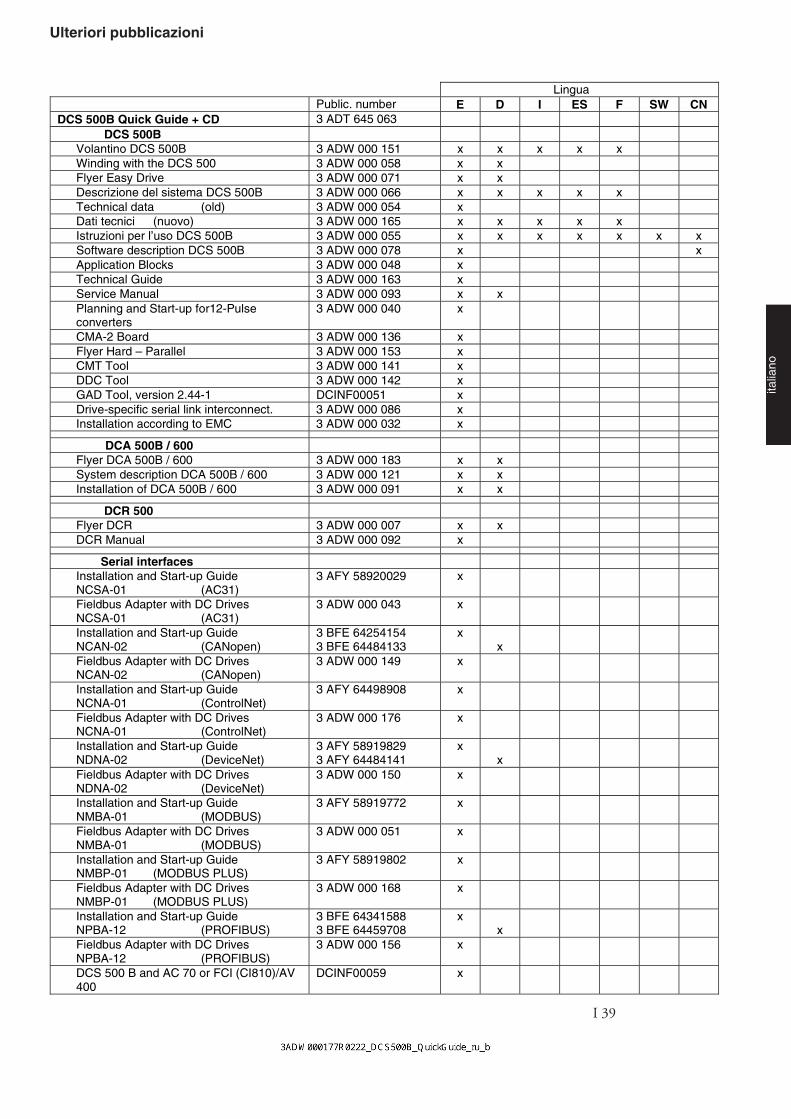
I 39
italia
no
Ulteriori pubblicazioni
Lingua Public. number E D I ES F SW CN DCS 500B Quick Guide + CD 3 ADT 645 063 DCS 500B
Volantino DCS 500B 3 ADW 000 151 x x x x x Winding with the DCS 500 3 ADW 000 058 x x Flyer Easy Drive 3 ADW 000 071 x x Descrizione del sistema DCS 500B 3 ADW 000 066 x x x x x Technical data (old) 3 ADW 000 054 x Dati tecnici (nuovo) 3 ADW 000 165 x x x x x Istruzioni per l’uso DCS 500B 3 ADW 000 055 x x x x x x x Software description DCS 500B 3 ADW 000 078 x x Application Blocks 3 ADW 000 048 x Technical Guide 3 ADW 000 163 x Service Manual 3 ADW 000 093 x x Planning and Start-up for12-Pulse converters
3 ADW 000 040 x
CMA-2 Board 3 ADW 000 136 x Flyer Hard – Parallel 3 ADW 000 153 x CMT Tool 3 ADW 000 141 x DDC Tool 3 ADW 000 142 x GAD Tool, version 2.44-1 DCINF00051 x Drive-specific serial link interconnect. 3 ADW 000 086 x Installation according to EMC 3 ADW 000 032 x
DCA 500B / 600 Flyer DCA 500B / 600 3 ADW 000 183 x x System description DCA 500B / 600 3 ADW 000 121 x x Installation of DCA 500B / 600 3 ADW 000 091 x x
DCR 500 Flyer DCR 3 ADW 000 007 x x DCR Manual 3 ADW 000 092 x
Serial interfaces Installation and Start-up Guide NCSA-01 (AC31)
3 AFY 58920029 x
Fieldbus Adapter with DC Drives NCSA-01 (AC31)
3 ADW 000 043 x
Installation and Start-up Guide NCAN-02 (CANopen)
3 BFE 64254154 3 BFE 64484133
x x
Fieldbus Adapter with DC Drives NCAN-02 (CANopen)
3 ADW 000 149 x
Installation and Start-up Guide NCNA-01 (ControlNet)
3 AFY 64498908 x
Fieldbus Adapter with DC Drives NCNA-01 (ControlNet)
3 ADW 000 176 x
Installation and Start-up Guide NDNA-02 (DeviceNet)
3 AFY 58919829 3 AFY 64484141
x x
Fieldbus Adapter with DC Drives NDNA-02 (DeviceNet)
3 ADW 000 150 x
Installation and Start-up Guide NMBA-01 (MODBUS)
3 AFY 58919772 x
Fieldbus Adapter with DC Drives NMBA-01 (MODBUS)
3 ADW 000 051 x
Installation and Start-up Guide NMBP-01 (MODBUS PLUS)
3 AFY 58919802 x
Fieldbus Adapter with DC Drives NMBP-01 (MODBUS PLUS)
3 ADW 000 168 x
Installation and Start-up Guide NPBA-12 (PROFIBUS)
3 BFE 64341588 3 BFE 64459708
x x
Fieldbus Adapter with DC Drives NPBA-12 (PROFIBUS)
3 ADW 000 156 x
DCS 500 B and AC 70 or FCI (CI810)/AV 400
DCINF00059 x
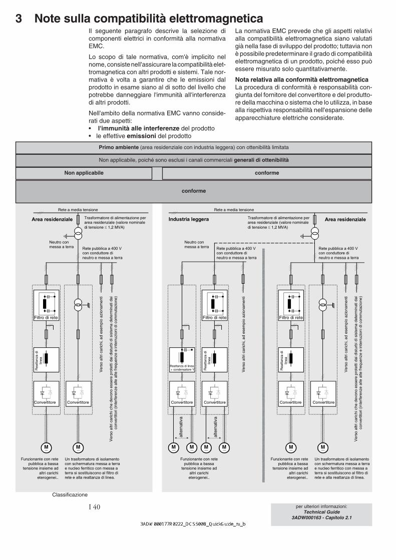
I 40 per ulteriori informazioni:Technical Guide
3ADW000163 - Capitolo 2.1
3 Note sulla compatibilità elettromagnetica
Classificazione
Non applicabile
Primo ambiente (area residenziale con industria leggera) con ottenibilità limitata
Non applicabile, poiché sono esclusi i canali commerciali generali di ottenibilità
conforme
conforme
Il seguente paragrafo descrive la selezione dicomponenti elettrici in conformità alla normativaEMC.
Lo scopo di tale normativa, com'è implicito nelnome, consiste nell'assicurare la compatibilità elet-tromagnetica con altri prodotti e sistemi. Tale nor-mativa è volta a garantire che le emissioni dalprodotto in esame siano al di sotto del livello chepotrebbe danneggiare l'immunità all'interferenzadi altri prodotti.
Nell'ambito della normativa EMC vanno conside-rati due aspetti:• l'immunità alle interferenze del prodotto• le effettive emissioni del prodotto
La nornativa EMC prevede che gli aspetti relativialla compatibilità elettromagnetica siano valutatigià nella fase di sviluppo del prodotto; tuttavia nonè possibile predeterminare il grado di compatibilitàelettromagnetica di un prodotto, poiché esso puòessere misurato solo quantitativamente.
Nota relativa alla conformità elettromagneticaLa procedura di conformità è responsabilità con-giunta del fornitore del convertitore e del produtto-re della macchina o sistema che lo utilizza, in basealla rispettiva responsabilità nell'espansione delleapparecchiature elettriche considerate.
MM
Filtro di rete
Convertitore
Rea
ttanz
a d
i lin
ea
Trasformatore di alimentazione per area residenziale (valore nominale di tensione ≤ 1,2 MVA)
Rete pubblica a 400 V con conduttore di neutro e messa a terra
Rete a media tensione
Neutro con messa a terra
Ve
rso
altr
i car
ich
i, a
d es
empi
o az
iona
men
ti
Un trasformatore di isolamento con schermatura messa a terra e nucleo ferritico con messa a terra si sostituiscono al filtro di rete e alla reattanza di linea.
Funzionante con rete pubblica a bassa
tensione insieme ad altri carichi
eterogenei..
Area residenziale
Ve
rso
altr
i car
ichi
che
dev
ono
esse
re p
rote
tti d
ai d
istu
rbi d
i sis
tem
a de
term
inat
i dai
co
nve
rtito
ri (
inte
rfer
enz
e al
le a
lte f
req
uenz
e e
inte
rru
zion
i di c
omm
utaz
ione
)
Convertitore
MMMM MM
Un trasformatore di isolamento con schermatura messa a terra e nucleo ferritico con messa a terra si sostituiscono al filtro di rete e alla reattanza di linea.
Funzionante con rete pubblica a bassa
tensione insieme ad altri carichi
eterogenei..
Neutro con messa a terra
alte
rnat
iva
Reattanza di linea + condensatore Y
Rete a media tensione
Ve
rso
altr
i car
ich
i, a
d es
empi
o az
iona
men
ti
Vers
o al
tri c
aric
hi, a
d es
empi
o az
iona
men
ti
Vers
o al
tri c
aric
hi c
he d
evon
o es
sere
pro
tetti
dai
dis
turb
i di s
iste
ma
dete
rmin
ati d
ai
conv
ertit
ori (
inte
rfere
nze
alle
alte
freq
uenz
e e
inte
rruzi
oni d
i com
mut
azio
ne)
Industria leggeraal
tern
ativ
a
Convertitore Convertitore
Rea
ttanz
a d
i lin
ea
Filtro di rete
Trasformatore di alimentazione per area residenziale (valore nominale di tensione ≤ 1,2 MVA)
Rete pubblica a 400 V con conduttore di neutro e messa a terra
Area residenziale
Rete pubblica a 400 V con conduttore di neutro e messa a terra
Filtro di rete
Rea
ttanz
a d
i lin
ea
Convertitore Convertitore
Funzionante con rete pubblica a bassa
tensione insieme ad altri carichi eterogenei..
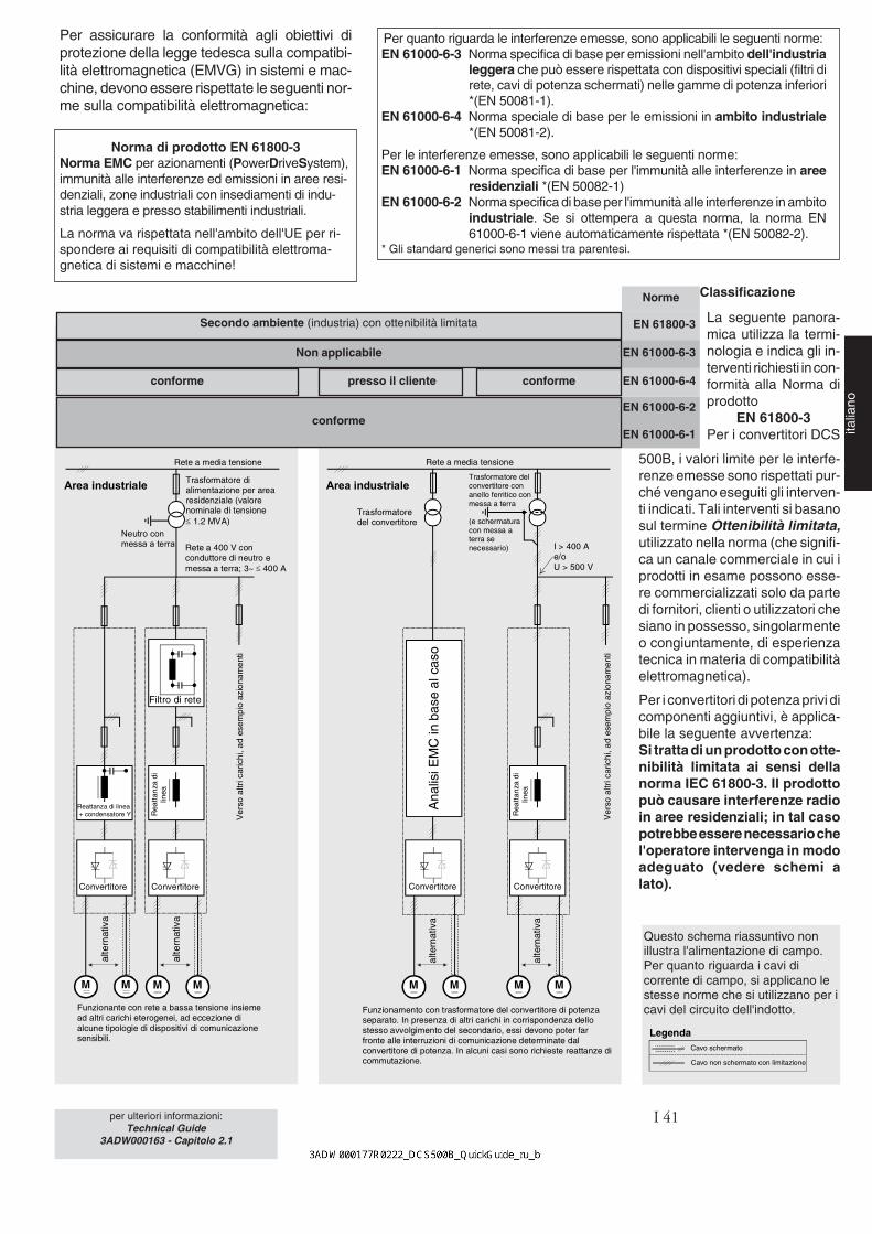
I 41
italia
no
per ulteriori informazioni:Technical Guide
3ADW000163 - Capitolo 2.1
Classificazione
La seguente panora-mica utilizza la termi-nologia e indica gli in-terventi richiesti in con-formità alla Norma diprodotto
EN 61800-3Per i convertitori DCS
Per assicurare la conformità agli obiettivi diprotezione della legge tedesca sulla compatibi-lità elettromagnetica (EMVG) in sistemi e mac-chine, devono essere rispettate le seguenti nor-me sulla compatibilità elettromagnetica:
Norma di prodotto EN 61800-3Norma EMC per azionamenti (PowerDriveSystem),immunità alle interferenze ed emissioni in aree resi-denziali, zone industriali con insediamenti di indu-stria leggera e presso stabilimenti industriali.
La norma va rispettata nell'ambito dell'UE per ri-spondere ai requisiti di compatibilità elettroma-gnetica di sistemi e macchine!
Questo schema riassuntivo nonillustra l'alimentazione di campo.Per quanto riguarda i cavi dicorrente di campo, si applicano lestesse norme che si utilizzano per icavi del circuito dell'indotto.
500B, i valori limite per le interfe-renze emesse sono rispettati pur-ché vengano eseguiti gli interven-ti indicati. Tali interventi si basanosul termine Ottenibilità limitata,utilizzato nella norma (che signifi-ca un canale commerciale in cui iprodotti in esame possono esse-re commercializzati solo da partedi fornitori, clienti o utilizzatori chesiano in possesso, singolarmenteo congiuntamente, di esperienzatecnica in materia di compatibilitàelettromagnetica).
Per i convertitori di potenza privi dicomponenti aggiuntivi, è applica-bile la seguente avvertenza:Si tratta di un prodotto con otte-nibilità limitata ai sensi dellanorma IEC 61800-3. Il prodottopuò causare interferenze radioin aree residenziali; in tal casopotrebbe essere necessario chel'operatore intervenga in modoadeguato (vedere schemi alato).
MMMM
Trasformatore di alimentazione per area residenziale (valore nominale di tensione ≤ 1.2 MVA)
Rete a 400 V con conduttore di neutro e messa a terra; 3~ ≤ 400 A
Funzionante con rete a bassa tensione insieme ad altri carichi eterogenei, ad eccezione di alcune tipologie di dispositivi di comunicazione sensibili.
Vers
o al
tri c
aric
hi, a
d es
empi
o az
iona
men
ti
Neutro con messa a terra
Rete a media tensione
Area industriale
alte
rnat
iva
alte
rnat
iva
Convertitore Convertitore
Rea
ttan
za d
i lin
ea
Reattanza di linea + condensatore Y
Filtro di rete
MMMM
Trasformatore del convertitore
Ana
lisi E
MC
in b
ase
al c
aso
alte
rnat
iva
Trasformatore del convertitore con anello ferritico con messa a terra
(e schermatura con messa a terra se necessario)
alte
rnat
iva
I > 400 A e/o U > 500 V
Funzionamento con trasformatore del convertitore di potenza separato. In presenza di altri carichi in corrispondenza dello stesso avvolgimento del secondario, essi devono poter far fronte alle interruzioni di comunicazione determinate dal convertitore di potenza. In alcuni casi sono richieste reattanze di commutazione.
Ver
so a
ltri c
aric
hi,
ad
esem
pio
azio
nam
enti
Rete a media tensione
Area industriale
Convertitore Convertitore
Rea
ttan
za d
i lin
ea
Legenda
Cavo non schermato con limitazione
Cavo schermato
Per quanto riguarda le interferenze emesse, sono applicabili le seguenti norme:EN 61000-6-3 Norma specifica di base per emissioni nell'ambito dell'industria
leggera che può essere rispettata con dispositivi speciali (filtri direte, cavi di potenza schermati) nelle gamme di potenza inferiori*(EN 50081-1).
EN 61000-6-4 Norma speciale di base per le emissioni in ambito industriale*(EN 50081-2).
Per le interferenze emesse, sono applicabili le seguenti norme:EN 61000-6-1 Norma specifica di base per l'immunità alle interferenze in aree
residenziali *(EN 50082-1)EN 61000-6-2 Norma specifica di base per l'immunità alle interferenze in ambito
industriale. Se si ottempera a questa norma, la norma EN61000-6-1 viene automaticamente rispettata *(EN 50082-2).
* Gli standard generici sono messi tra parentesi.
EN 61800-3
EN 61000-6-3
EN 61000-6-4
EN 61000-6-2
EN 61000-6-1
conforme
conforme
Secondo ambiente (industria) con ottenibilità limitata
presso il cliente conforme
Non applicabile
Norme
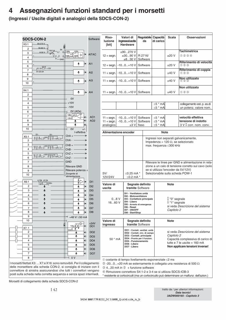
I 42 tratto da / per ulteriori informazioni:Data tecnici
3ADW000165 - Capitolo 3
4 Assegnazioni funzioni standard per i morsetti(Ingressi / Uscite digitali e analogici della SDCS-CON-2)
Morsetti di collegamento della scheda SDCS-CON-2
Riso- Valori di Regolabile Capacità Scala Osservazioniluzione ingresso/uscita da di carico
[bit] Hardware
±90...270 V12 + segn. ±30...90 V R 2716/ ±20 V ➀ ➁ ➂ ➃
±8...30 V Software
12 + segn. -10...0...+10 V Software ±20 V ➀ ➁ ➂
11 + segn. -10...0...+10 V Software ±40 V ➀ ➁ ➂
11 + segn. -10...0...+10 V Software ±40 V ➀ ➁ ➂
11 + segn. -10...0...+10 V Software ±40 V ➀ ➁ ➂
≤5 * mA collegamento est. p. es.di≤5 * mA un potenz. valore nom.
11 + segn. -10...0...+10 V Software ≤5 * mA11 + segn. -10...0...+10 V Software ≤5 * mAanalogico ±3 V fisso ≤5 * mA 3 V = corr. nom. conv.
Alimentazione encoder Note
Ingressi non separati galvanicamente,Impedenza = 120 Ω, se selezionatomax. frequenza ≤300 kHz
Rilevare le linee per GND e alimentazione in rela-zione a un calo di tensione corretto sul cavo (solose si utilizza l'encoder da 5V/12V)
5V/ ≤0.25 mA * Selezionabile sulla scheda POW-112V/24V ≤0.2 mA *
Valore di Segnale definito Noteuscita tramite Software
0...8 V = "0" segnale16...60 V = "1" segnale
si veda Descrizione del sistemaCapitolo 2
Valore di Segnale definito Noteingresso tramite Software
si veda Descrizione del sistemaCapitolo 2
50 * mA Capacità complessiva di carico ditutte e 7 le uscite = 160 mANon applicare tensioni inverse!
➀ costante di tempo livellamento esponenziale ≤2 ms➁ -20...0...+20 mA se esternamente è collegata una resistenza di 500 Ω➂ 4...20 mA in ➁ + funzione software➃ Rimuovere connettore S4:1-2 e 3-4 se si utilizza SDCS-IOB-3* resistente ai cortocircuiti (ma un cortocircuito può determinare un malfunz. dell'azion.)
I morsetti filettati X3: ... X7:e X16: sono removibili. Per il collegamentodelle morsettiere alla scheda CON-2, si consiglia di iniziare con ilconnettore di sinistra assicurandosi che tutti i connettori venganoposti sulla scheda nella corretta sequenza e senza spazi intermedi.
X2:
X1:
AITAC
90-270 V
30-90 V
8-30 V
+24V
AI4
ChA +
ChA -
ChB +
ChB -
ChZ +
ChZ -
GND
0 V
R2716
+10V
S1:23-24
100µ
+48 V/ ≤50 mA
100k
1n1n
100n
100k
100k 100k
Power-Source
Sense GND
Sense Power +
0V
AI2
AI3
AI1
-
+
-
+
-
+
-
-
-
+
AO1AO2
+/- I-act
47.5100µ
100n
0V (AOx)
+10V
0V
-10V
DI1
DI2
DI3
DI4DI5
DI6
DI7
DI8
47.5k
220n10k
4.75k
DO4
DO5
DO7
DO1
DO2
DO3
DO6
22 K
3
4
5
8
7
6
7
9
X6:1
2
3
4
5
6
7 8
10
4
5
7
1
2
3
6
4
2
3
6
5
9
10
8
9
10
2
4
5
7
2
3
6
8
9
10
8
X3:1
X4:1
X5:1
X7:
SDCS-CON-2 Software
+24V 7 8 910 11 12
+24V 13141516 17 18
+24V4 5 6
S1:1 2 3
S1:
GND
1 2
3 456
S4
+/- I-effettiva
Sorgente di alimentazione
Rilevare GNDRilevare potenza +
Riferimento di velocità
Tachimetrica
Riferimento di coppia
Non utilizzato
Non utilizzato
velocità effettivatensione di indotto
DI1 - Ventilatore unitàDI2 - MotoventilatoreDI3 - Contattore principaleDI4 - LiberoDI5 - Arresto di emergenzaDI6 - ResetDI7 - ON/OFFDI8 - Start/Stop
DO1 - Contatt. ventilat. unitàDO2 - Contatt. circ. di campoDO3 - Contatt. principaleDO4 - Pronto per il funzion.DO5 - FunzionamentoDO6 - LiberoDO7 - Libero
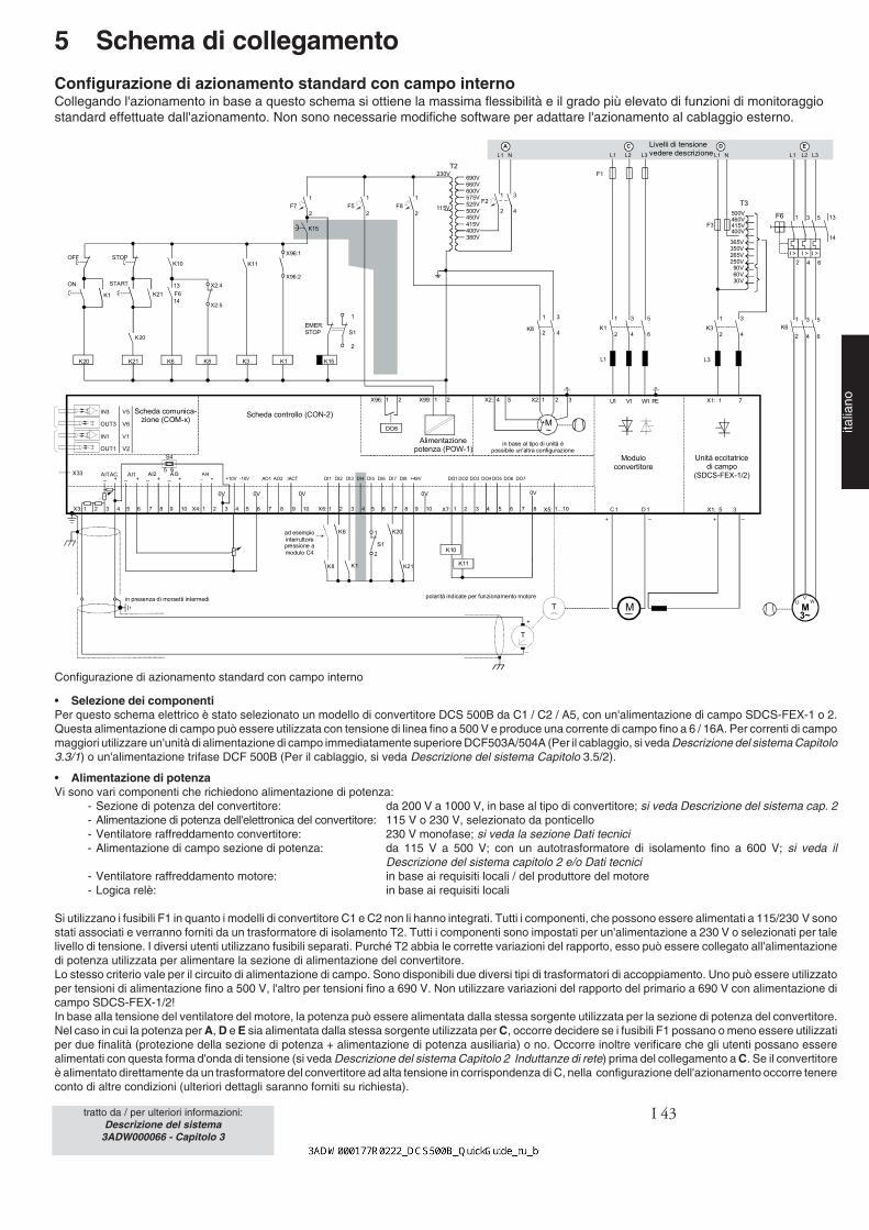
I 43
italia
no
5 Schema di collegamento
tratto da / per ulteriori informazioni:Descrizione del sistema
3ADW000066 - Capitolo 3
Configurazione di azionamento standard con campo interno
Configurazione di azionamento standard con campo internoCollegando l'azionamento in base a questo schema si ottiene la massima flessibilità e il grado più elevato di funzioni di monitoraggiostandard effettuate dall'azionamento. Non sono necessarie modifiche software per adattare l'azionamento al cablaggio esterno.
• Selezione dei componentiPer questo schema elettrico è stato selezionato un modello di convertitore DCS 500B da C1 / C2 / A5, con un'alimentazione di campo SDCS-FEX-1 o 2.Questa alimentazione di campo può essere utilizzata con tensione di linea fino a 500 V e produce una corrente di campo fino a 6 / 16A. Per correnti di campomaggiori utilizzare un'unità di alimentazione di campo immediatamente superiore DCF503A/504A (Per il cablaggio, si veda Descrizione del sistema Capitolo3.3/1) o un'alimentazione trifase DCF 500B (Per il cablaggio, si veda Descrizione del sistema Capitolo 3.5/2).
• Alimentazione di potenzaVi sono vari componenti che richiedono alimentazione di potenza:
- Sezione di potenza del convertitore: da 200 V a 1000 V, in base al tipo di convertitore; si veda Descrizione del sistema cap. 2- Alimentazione di potenza dell'elettronica del convertitore: 115 V o 230 V, selezionato da ponticello- Ventilatore raffreddamento convertitore: 230 V monofase; si veda la sezione Dati tecnici- Alimentazione di campo sezione di potenza: da 115 V a 500 V; con un autotrasformatore di isolamento fino a 600 V; si veda il
Descrizione del sistema capitolo 2 e/o Dati tecnici- Ventilatore raffreddamento motore: in base ai requisiti locali / del produttore del motore- Logica relè: in base ai requisiti locali
Si utilizzano i fusibili F1 in quanto i modelli di convertitore C1 e C2 non li hanno integrati. Tutti i componenti, che possono essere alimentati a 115/230 V sonostati associati e verranno forniti da un trasformatore di isolamento T2. Tutti i componenti sono impostati per un'alimentazione a 230 V o selezionati per talelivello di tensione. I diversi utenti utilizzano fusibili separati. Purché T2 abbia le corrette variazioni del rapporto, esso può essere collegato all'alimentazionedi potenza utilizzata per alimentare la sezione di alimentazione del convertitore.Lo stesso criterio vale per il circuito di alimentazione di campo. Sono disponibili due diversi tipi di trasformatori di accoppiamento. Uno può essere utilizzatoper tensioni di alimentazione fino a 500 V, l'altro per tensioni fino a 690 V. Non utilizzare variazioni del rapporto del primario a 690 V con alimentazione dicampo SDCS-FEX-1/2!In base alla tensione del ventilatore del motore, la potenza può essere alimentata dalla stessa sorgente utilizzata per la sezione di potenza del convertitore.Nel caso in cui la potenza per A, D e E sia alimentata dalla stessa sorgente utilizzata per C, occorre decidere se i fusibili F1 possano o meno essere utilizzatiper due finalità (protezione della sezione di potenza + alimentazione di potenza ausiliaria) o no. Occorre inoltre verificare che gli utenti possano esserealimentati con questa forma d'onda di tensione (si veda Descrizione del sistema Capitolo 2 Induttanze di rete) prima del collegamento a C. Se il convertitoreè alimentato direttamente da un trasformatore del convertitore ad alta tensione in corrispondenza di C, nella configurazione dell'azionamento occorre tenereconto di altre condizioni (ulteriori dettagli saranno forniti su richiesta).
IN3
OUT3
IN1
OUT1
V5
V6
V1
V2
X96:
DO8
1 2 X99: 1 2 X2: 4 5 X2: 1 2 3 U1 W1V1 PE
K1 F6
K20
K21K20 K3 K1
X96:1
X96:2
L1 L2 L3
F1
F3
K31 3
2 4
M~
T3F23
4
1
2
T2690V660V600V575V525V500V450V415V400V380V
115V
230V
K15
K15
S1
1
2
K6 K8
X2:4
X2:5
K11K10
K21
500V460V415V400V
365V350V265V250V90V60V30V
X33
C 1 D 1
AITAC AI1 AI2 AI3 AI4+10V -10V AO1 AO2 IACT DI1 DI2 DI3 DI4 DI5 DI6 DI7 DI8 +48V DO1 DO2 DO3 DO4 DO5 DO6 DO7_ _ _ _ _+ + + + +
T
T M
0V0V0V0V0V
X3: 1 2 3 4 5 6 7 8 9 10 X4: 1 2 3 4 5 6 7 8 9 10 X6: 1 2 3 4 5 6 7 8 9 10 X7: 1 2 3 4 5 6 7 8 1...10X5:+ _
+
_
K1
K20
K21
K6
K8
1
2
S1
K11
K10
S4
5 6
2 4 6
1 3 5K6
F51
2F8
1
2F7
1
2
2
1
4
3
6
5F6
I > I > I >
13
14
UV
WM3~
K11 3 5
2 4 6
L1
1
2
3
4K8
13
14
X1: 1 7
L3
X1: 5 3+ _
L1 N L1 N L1 L2 L3A C D E
Scheda comunica-zione (COM-x) Scheda controllo (CON-2)
Alimentazionepotenza (POW-1)
Moduloconvertitore
ON
OFF STOP
START
EMER.STOP
Unitá eccitatricedi campo
(SDCS-FEX-1/2)
in base al tipo di unità è possibile un'altra configurazione
polarità indicate per funzionamento motorein presenza di morsetti intermedi
ad esempio interruttore pressione a modulo C4
Livelli di tensionevedere descrizione
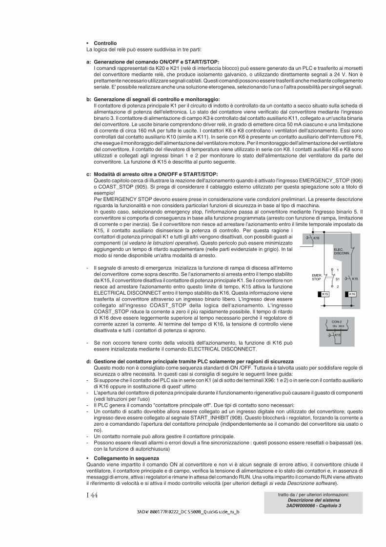
I 44 tratto da / per ulteriori informazioni:Descrizione del sistema
3ADW000066 - Capitolo 3
• ControlloLa logica del relè può essere suddivisa in tre parti:
a: Generazione del comando ON/OFF e START/STOP:I comandi rappresentati da K20 e K21 (relè di interfaccia blocco) può essere generato da un PLC e trasferito ai morsettidel convertitore mediante relè, che produce isolamento galvanico, o utilizzando direttamente segnali a 24 V. Non èprettamente necessario utilizzare segnali cablati. Questi comandi possono essere trasferiti anche mediante collegamentoseriale. E' possibile realizzare anche una soluzione eterogenea, selezionando l'una o l'altra possibilità per singoli segnali.
b: Generazione di segnali di controllo e monitoraggio:Il contattore di potenza principale K1 per il circuito di indotto è controllato da un contatto a secco situato sulla scheda dialimentazione di potenza dell'elettronica. Lo stato del contattore viene verificato dal convertitore mediante l'ingressobinario 3. Il contattore di alimentazione di campo K3 è controllato dal contatto ausiliario K11, collegato a un'uscita binariadel convertitore. Le uscite binarie comprendono driver relè, in grado di emettere circa 50 mA ciascuno e una limitazionedi corrente di circa 160 mA per tutte le uscite. I contattori K6 e K8 controllano i ventilatori dell'azionamento. Essi sonocontrollati dal contatto ausiliario K10 (simile a K11). In serie con K6 è presente un contatto ausiliario dell'interruttore F6,che esegue il monitoraggio dell'alimentazione del ventilatore motore. Per il monitoraggio dell'alimentazione del ventilatoredel convertitore, il contatto del rilevatore di temperatura viene utilizzato in serie con K8. I contatti ausiliari K6 e K8 sonoutilizzati e collegati agli ingressi binari 1 e 2 per monitorare lo stato dell'alimentazione del ventilatore da parte delconvertitore. La funzione di K15 è descritta al punto seguente.
c: Modalità di arresto oltre a ON/OFF e START/STOP:Questo capitolo cerca di illustrare la reazione dell'azionamento quando è attivato l'ingresso EMERGENCY_STOP (906)o COAST_STOP (905). Si prega di considerare il cablaggio esterno utilizzato per questa spiegazione solo a titolo diesempio!Per EMERGENCY STOP devono essere prese in considerazione varie condizioni preliminari. La presente descrizioneriguarda la funzionalità e non considera particolari funzioni di sicurezza in base al tipo di macchina.In questo caso, selezionando emergency stop, l'informazione passa al convertitore mediante l'ingresso binario 5. Ilconvertitore si comporta di conseguenza in base alla funzione programmata (arresto con funzione di rampa, limitazionedi corrente o per inerzia). Se il convertitore non riesce ad arrestare l'azionamento entro il limite temporale impostato daK15, il contatto ausiliario disinserisce la potenza di controllo. Per questa ragione icontattori di potenza principali K1 e tutti gli altri vengono disattivati, con possibili guasti aicomponenti (si vedano le Istruzioni operative). Questo pericolo può essere minimizzatoaggiungendo un tempo di ritardo supplementare (nelle parti evidenziate in grigio). In talmodo si rende disponibile un'altra modalità di arresto.
- Il segnale di arresto di emergenza inizializza la funzione di rampa di discesa all'internodel convertitore come sopra descritto. Se l'azionamento si arresta entro il tempo stabilitoda K15, il convertitore disattiva il contattore di potenza principale K1. Se il convertitore nonriesce ad arrestare l'azionamento entro questo limite di tempo, K15 attiva la funzioneELECTRICAL DISCONNECT entro il tempo stabilito da K16. Questa informazione vienetrasferita al convertitore attraverso un ingresso binario libero. L'ingresso deve esserecollegato all'ingresso COAST_STOP della logica dell'azionamento. L'ingressoCOAST_STOP riduce la corrente a zero il più rapidamente possibile. Il tempo di ritardodi K16 deve essere leggermente superiore al tempo necessario perché il regolatore dicorrente azzeri la corrente. Al termine del tempo di K16, la tensione di controllo vienedisattivata e tutti i contattori di potenza si aprono.
- Se non occorre tenere conto della velocità dell'azionamento, la funzione di K16 puòessere inizializzata mediante il comando ELECTRICAL DISCONNECT.
d: Gestione del contattore principale tramite PLC solamente per ragioni di sicurezzaQuesto modo non è consigliato come sequenza standard di ON /OFF. Tuttavia è talvolta usato per soddisfare regole disicurezza o altre necessità. In questi casi si consiglia di seguire le seguenti linee guida:
- Si suppone che il contatto del PLC sia in serie con K1 (al di sotto dei terminali X96: 1 e 2) o in serie con il contatto ausiliariodi K16 oppure in sostituzione di quest' ultimo
- L'apertura del contattore di potenza principale durante il funzionamento rigenerativo può causare il guasto di componenti(vedi Istruzioni per l'uso)
- Il PLC genera il comando "contattore principale off". Due tipi di contatto sono necessari:- Un contatto di scatto dovrebbe allora essere collegato ad un ingresso digitale non utilizzato del convertitore; questo
ingresso deve essere collegato al segnale START_INHIBIT (908). Questo bloccherà i regolatori, forzando la corrente azero e comandando l'apertura del contattore principale (indipendentemente se il comando del convertitore sia usato ono).
- Un contatto normale può allora gestire il contattore principale.- Possono essere rilevati allarmi o errori dovuti a fine sincronizzazione : questi possono essere resettati o baipassati (es.
con la funzione di autorichiusura)
• Collegamento in sequenzaQuando viene impartito il comando ON al convertitore e non vi è alcun segnale di errore attivo, il convertitore chiude ilventilatore, il contattore principale e di campo, verifica la tensione di alimentazione e lo stato dei contattori e, in assenza dimessaggi di errore, attiva i regolatori e rimane in attesa del comando RUN. Una volta impartito il comando RUN viene attivatoil riferimento di velocità e si attiva il modo controllo velocità (per ulteriori dettagli si veda Descrizione software).
EMER.STOP
K16
K15 K16
K15
ELEC.DISCONN.
DIx
K15
X6:9CON-2
S1
1
2
I 45
italia
no
1. Prescrizioni generaliConvertitori di frequenza relativo al loro grado di protezionepossono avere durante il funzionamento parti sotto tensione nonisolati, parti mobili o rotanti e superfici con temperature elevati.
Nei casi di rimozione non ammessa di parti dell’ involucronecessari per la protezione, di utilizzo improprio e installazione e/o impiego non corretto sussiste grave pericolo per persone ocose.
Ulteriori informazioni sono contenute nei rispettivi manuali.
Tutti i lavori di trasporto, installazione, messa in funzione emanutenzione devono essere eseguiti da personale qualificatoed autorizzato (osservare le norme IEC 364, CENELEC HD 384o DIN VDE 0100 e IEC 664 o DIN VDE 0110 e normeantiinfortunistiche nazionali).
Negli avvisi di sicurezza come personale qualificato, si intendonotecnici specializzati all’ installazione, il montaggio, la messa infunzione ed il funzionamento del apparato, con specificheconoscenze e qualifiche.
2. Uso appropriatoI convertitori di frequenza sono componenti destinati ad essereincorporati in impianti o macchine.
Se il convertitore viene integrato in una macchina, questo nonpotrà essere messo in servizio affinchè la macchina stessa nonrisponderà ai requisiti della Direttiva 89/392/CEE (DirettivaMacchine); La norma EN 60204 deve essere rispettata.
La messa in servizio è concessa solo se la Direttiva EMC (89/336/CEE) viene rispettata.
I convertitori di frequenza sono conformi alle esigenze dellaDirettiva Bassa Tensione 73/23/CEE. Per i convertitori di fre-quenza vengono applicate le norme armonizzate della serie prEN50178/DIN VDE 0160 in combinazione con le norme EN 60439-1/DIN VDE 0660 parte 500 e EN 60146/DIN VDE 0558.
Dati tecnici e indicazioni per l’ allacciamento sono riportati siasulla targa d’ identificazione che nella documentazione tecnica edevono essere rispettati in ogni caso.
3. Trasporto, ImmagazzinamentoGli avvisi per il trasporto, l’ immagazinamento e la manipolazionedevono essere osservati scrupolosamente.
Le condizioni climatiche secondo prEN 50178 devono essererispettate.
4. MontaggioPer il montaggio ed il raffreddamento degli apparecchi devonoessere rispettate le prescrizioni contenute nella documentazione.
I convertitori di frequenza devono essere protetti da condizioni dilavoro inamissibili. Durante il trasporto e la manipolazione si devefare particolare attenzione a non piegare componenti e/o amodificare distanze d’ isolamento. Evitare il contatto con altricomponenti elettronici o contatti elettrici.
I convertitori di frequenza contengono componenti elettronicisensibili a scariche elettrostatiche, che possono essere danneg-giati facilmente se maneggiati in modo non corretto.Componentielettrici non devono essere danneggiati o distrutti meccanicamen-te. (eventualmente potrebbe sussistere pericolo per la salute!).
5. Collegamento elettricoIn caso di lavori sul convertitore di frequenza sotto tensionedevono essere osservate le norme antiinfortrunistiche nazionali invigore.
L’ installazione elettrica deve essere eseguita secondo le normevigenti (p.es. sezione cavi, dispositivi di protezione controsovvracorrenti, collegamento circuito di protezioneequipotenziale). Ulteriori avvisi cono contenuti nella documenta-zione.
Indicazioni per eventuali accorgimenti antidisturbo - comeschermatura, messa a terra, disposizione di filtri e posa dicondutture - sono contenuti nella documentazione tecnica.Questeindicazioni devono essere osservate anche in caso di convertitorimuniti di marchio CE. L’ adempimento dei limiti richiesti dallalegislazione EMC è di reponsabilità del costruttore dell’ impiantoo della macchina.
6. FunzionamentoImpianti dotati di convertitori di frequenza devono essere equi-paggiati eventualmente con impianti di sorveglianza o protezioneaggiuntivi conformi alle vigenti norme di sicurezza.
Sono ammesse modifiche ai convertitori di frequenza tramite ilsoftware di gestione.
Dopo aver staccato il convertitore dalla rete di alimentazione nonsi devono toccare subito parti sotto tensione e morsetti di collega-mento a causa di condensatori ancora carichi. A questo propositodevono essere osservati i relativi indicazioni di avvertimentopresenti sul involucro del convertitore.
Durante il funzionamento coperchi e porte del involucro devonorimanere chiusi.
7. ManutenzioneLe prescrizioni del costruttore devono essere rispettati.
Questi avvisi di sicurezza devono essere conservati!
6 Istruzioni per la sicurezza
di convertitori di frequenza DCS / DCF / DCR
(secondo: Direttiva Bassa Tensione 73/23/CEE)
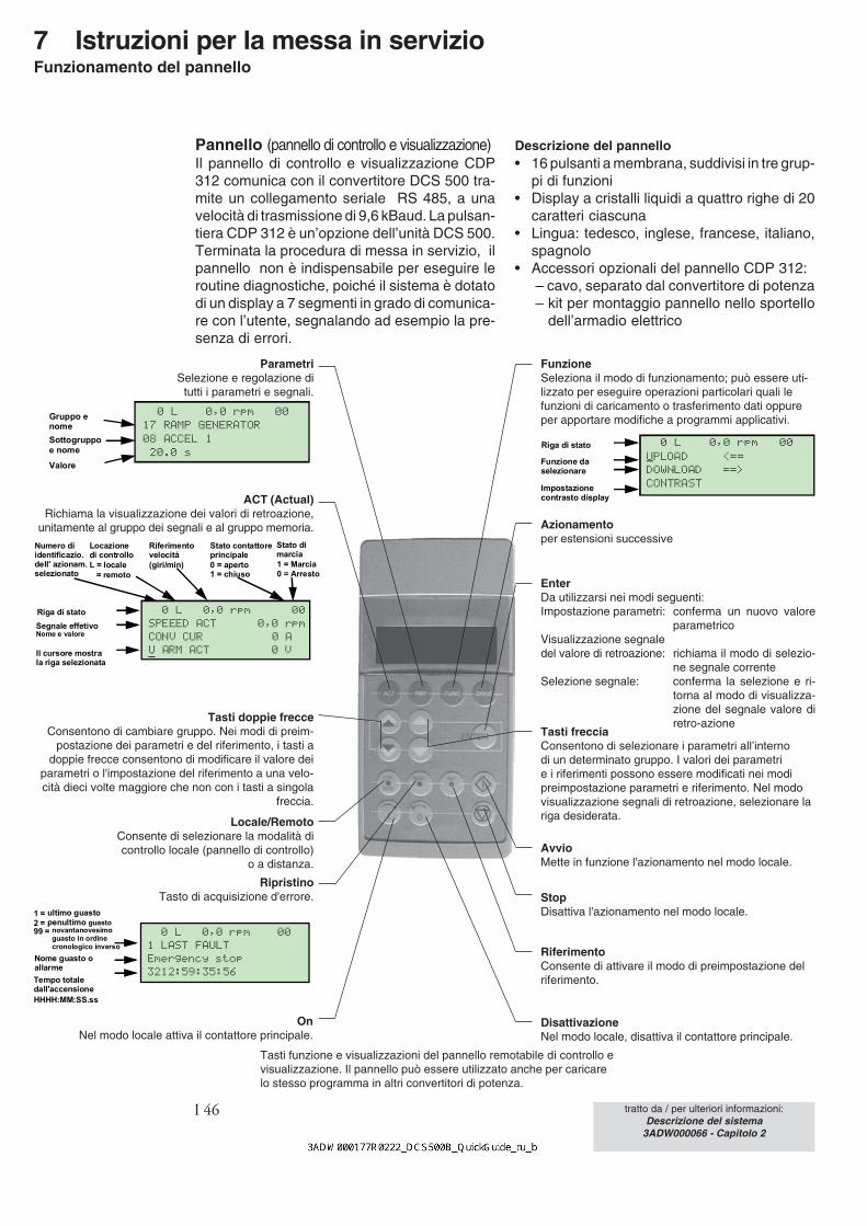
I 46
7 Istruzioni per la messa in servizioFunzionamento del pannello
tratto da / per ulteriori informazioni:Descrizione del sistema
3ADW000066 - Capitolo 2
Pannello (pannello di controllo e visualizzazione)Il pannello di controllo e visualizzazione CDP312 comunica con il convertitore DCS 500 tra-mite un collegamento seriale RS 485, a unavelocità di trasmissione di 9,6 kBaud. La pulsan-tiera CDP 312 è un’opzione dell’unità DCS 500.Terminata la procedura di messa in servizio, ilpannello non è indispensabile per eseguire leroutine diagnostiche, poiché il sistema è dotatodi un display a 7 segmenti in grado di comunica-re con l’utente, segnalando ad esempio la pre-senza di errori.
Tasti funzione e visualizzazioni del pannello remotabile di controllo evisualizzazione. Il pannello può essere utilizzato anche per caricarelo stesso programma in altri convertitori di potenza.
ACT (Actual)Richiama la visualizzazione dei valori di retroazione,
unitamente al gruppo dei segnali e al gruppo memoria.
ParametriSelezione e regolazione di
tutti i parametri e segnali.
FunzioneSeleziona il modo di funzionamento; può essere uti-lizzato per eseguire operazioni particolari quali lefunzioni di caricamento o trasferimento dati oppureper apportare modifiche a programmi applicativi.
Azionamentoper estensioni successive
Tasti doppie frecceConsentono di cambiare gruppo. Nei modi di preim-
postazione dei parametri e del riferimento, i tasti adoppie frecce consentono di modificare il valore dei
parametri o l'impostazione del riferimento a una velo-cità dieci volte maggiore che non con i tasti a singola
freccia.
Tasti frecciaConsentono di selezionare i parametri all’internodi un determinato gruppo. I valori dei parametrie i riferimenti possono essere modificati nei modipreimpostazione parametri e riferimento. Nel modovisualizzazione segnali di retroazione, selezionare lariga desiderata.
EnterDa utilizzarsi nei modi seguenti:Impostazione parametri: conferma un nuovo valore
parametricoVisualizzazione segnaledel valore di retroazione: richiama il modo di selezio-
ne segnale correnteSelezione segnale: conferma la selezione e ri-
torna al modo di visualizza-zione del segnale valore diretro-azione
Locale/RemotoConsente di selezionare la modalità dicontrollo locale (pannello di controllo)
o a distanza.
RipristinoTasto di acquisizione d'errore.
RiferimentoConsente di attivare il modo di preimpostazione delriferimento.
AvvioMette in funzione l'azionamento nel modo locale.
StopDisattiva l'azionamento nel modo locale.
OnNel modo locale attiva il contattore principale.
DisattivazioneNel modo locale, disattiva il contattore principale.
Descrizione del pannello• 16 pulsanti a membrana, suddivisi in tre grup-
pi di funzioni• Display a cristalli liquidi a quattro righe di 20
caratteri ciascuna• Lingua: tedesco, inglese, francese, italiano,
spagnolo• Accessori opzionali del pannello CDP 312:
– cavo, separato dal convertitore di potenza– kit per montaggio pannello nello sportello
dell’armadio elettrico
0 L 0,0 rpm 00 17 RAMP GENERATOR08 ACCEL 1 20.0 s
Gruppo enome Sottogruppoe nomeValore
0 L 0,0 rpm 00SPEEED ACT 0,0 rpmCONV CUR 0 AU ARM ACT 0 V
Numero diidentificazio.dell' azionam.selezionato
Locazionedi controlloL = locale = remoto
Stato contattoreprincipale0 = aperto1 = chiuso
Riferimentovelocitá(giri/min)
Stato dimarcia1 = Marcia0 = Arresto
Riga di statoSegnale effetivoNome e valore
Il cursore mostrala riga selezionata
0 L 0,0 rpm 001 LAST FAULTEmergency stop3212:59:35:56
1 = ultimo guasto2 = penultimo guasto99 = novantanovesimo
guasto in ordinecronologico inverso
Tempo totale dall'accensioneHHHH:MM:SS.ss
Nome guasto o allarme
0 L 0,0 rpm 00UPLOAD <==DOWNLOAD ==>CONTRAST
Riga di stato
Funzione da selezionare
Impostazionecontrasto display
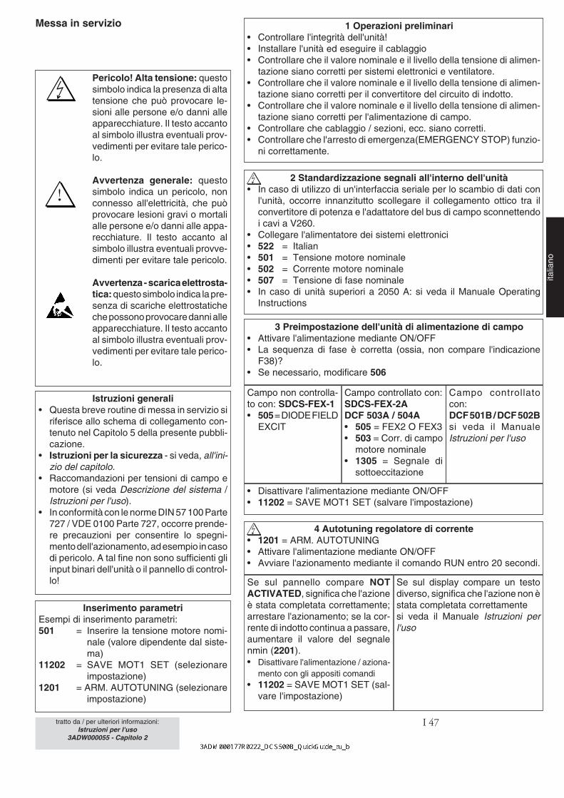
I 47
italia
no
Messa in servizio
tratto da / per ulteriori informazioni:Istruzioni per l'uso
3ADW000055 - Capitolo 2
Pericolo! Alta tensione: questosimbolo indica la presenza di altatensione che può provocare le-sioni alle persone e/o danni alleapparecchiature. Il testo accantoal simbolo illustra eventuali prov-vedimenti per evitare tale perico-lo.
Avvertenza generale: questosimbolo indica un pericolo, nonconnesso all'elettricità, che puòprovocare lesioni gravi o mortalialle persone e/o danni alle appa-recchiature. Il testo accanto alsimbolo illustra eventuali provve-dimenti per evitare tale pericolo.
Avvertenza - scarica elettrosta-tica: questo simbolo indica la pre-senza di scariche elettrostaticheche possono provocare danni alleapparecchiature. Il testo accantoal simbolo illustra eventuali prov-vedimenti per evitare tale perico-lo.
1 Operazioni preliminari• Controllare l'integrità dell'unità!• Installare l'unità ed eseguire il cablaggio• Controllare che il valore nominale e il livello della tensione di alimen-
tazione siano corretti per sistemi elettronici e ventilatore.• Controllare che il valore nominale e il livello della tensione di alimen-
tazione siano corretti per il convertitore del circuito di indotto.• Controllare che il valore nominale e il livello della tensione di alimen-
tazione siano corretti per l'alimentazione di campo.• Controllare che cablaggio / sezioni, ecc. siano corretti.• Controllare che l'arresto di emergenza(EMERGENCY STOP) funzio-
ni correttamente.
2 Standardizzazione segnali all'interno dell'unità• In caso di utilizzo di un'interfaccia seriale per lo scambio di dati con
l'unità, occorre innanzitutto scollegare il collegamento ottico tra ilconvertitore di potenza e l'adattatore del bus di campo sconnettendoi cavi a V260.
• Collegare l'alimentatore dei sistemi elettronici• 522 = Italian• 501 = Tensione motore nominale• 502 = Corrente motore nominale• 507 = Tensione di fase nominale• In caso di unità superiori a 2050 A: si veda il Manuale Operating
Instructions
3 Preimpostazione dell'unità di alimentazione di campo• Attivare l'alimentazione mediante ON/OFF• La sequenza di fase è corretta (ossia, non compare l'indicazione
F38)?• Se necessario, modificare 506
Campo non controlla-to con: SDCS-FEX-1• 505 = DIODE FIELD
EXCIT
Campo controllato con:SDCS-FEX-2ADCF 503A / 504A• 505 = FEX2 O FEX3• 503 = Corr. di campo
motore nominale• 1305 = Segnale di
sottoeccitazione
Campo controllatocon:DCF 501B / DCF 502Bsi veda il ManualeIstruzioni per l'uso
• Disattivare l'alimentazione mediante ON/OFF• 11202 = SAVE MOT1 SET (salvare l'impostazione)
4 Autotuning regolatore di corrente• 1201 = ARM. AUTOTUNING• Attivare l'alimentazione mediante ON/OFF• Avviare l'azionamento mediante il comando RUN entro 20 secondi.
Se sul pannello compare NOTACTIVATED, significa che l'azioneè stata completata correttamente;arrestare l'azionamento; se la cor-rente di indotto continua a passare,aumentare il valore del segnalenmin (2201).• Disattivare l'alimentazione / aziona-
mento con gli appositi comandi• 11202 = SAVE MOT1 SET (sal-
vare l'impostazione)
Se sul display compare un testodiverso, significa che l'azione non èstata completata correttamentesi veda il Manuale Istruzioni perl'uso
Inserimento parametriEsempi di inserimento parametri:501 = Inserire la tensione motore nomi-
nale (valore dipendente dal siste-ma)
11202 = SAVE MOT1 SET (selezionareimpostazione)
1201 = ARM. AUTOTUNING (selezionareimpostazione)
Istruzioni generali• Questa breve routine di messa in servizio si
riferisce allo schema di collegamento con-tenuto nel Capitolo 5 della presente pubbli-cazione.
• Istruzioni per la sicurezza - si veda, all'ini-zio del capitolo.
• Raccomandazioni per tensioni di campo emotore (si veda Descrizione del sistema /Istruzioni per l'uso).
• In conformità con le norme DIN 57 100 Parte727 / VDE 0100 Parte 727, occorre prende-re precauzioni per consentire lo spegni-mento dell'azionamento, ad esempio in casodi pericolo. A tal fine non sono sufficienti gliinput binari dell'unità o il pannello di control-lo!
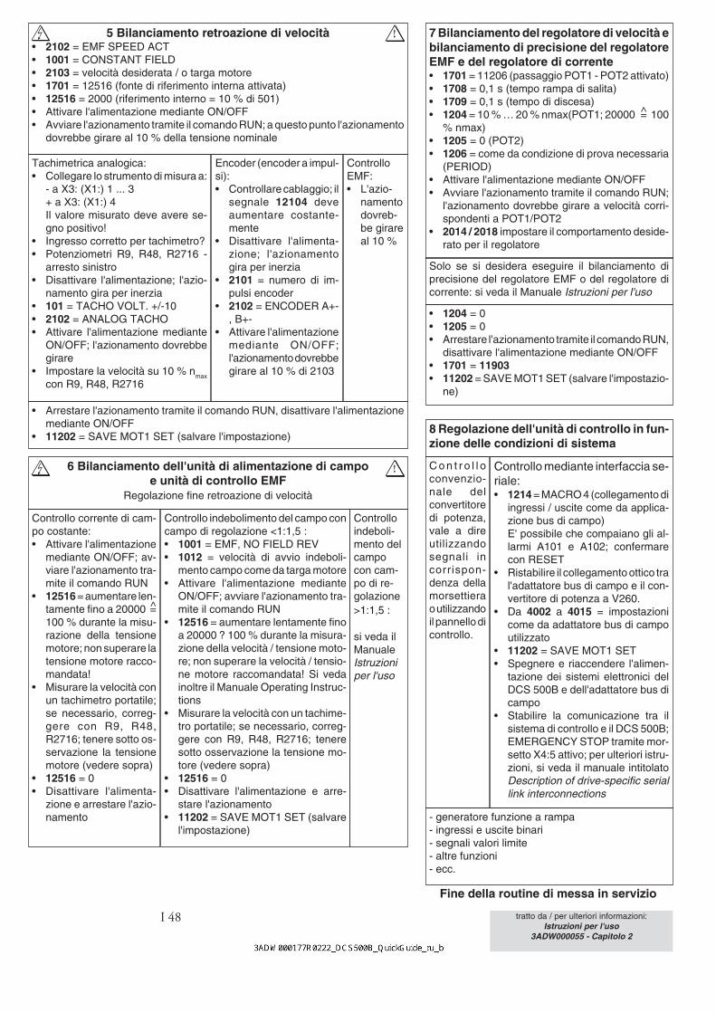
I 48 tratto da / per ulteriori informazioni:Istruzioni per l'uso
3ADW000055 - Capitolo 2
5 Bilanciamento retroazione di velocità• 2102 = EMF SPEED ACT• 1001 = CONSTANT FIELD• 2103 = velocità desiderata / o targa motore• 1701 = 12516 (fonte di riferimento interna attivata)• 12516 = 2000 (riferimento interno = 10 % di 501)• Attivare l'alimentazione mediante ON/OFF• Avviare l'azionamento tramite il comando RUN; a questo punto l'azionamento
dovrebbe girare al 10 % della tensione nominale
Tachimetrica analogica:• Collegare lo strumento di misura a:
- a X3: (X1:) 1 ... 3+ a X3: (X1:) 4Il valore misurato deve avere se-gno positivo!
• Ingresso corretto per tachimetro?• Potenziometri R9, R48, R2716 -
arresto sinistro• Disattivare l'alimentazione; l'azio-
namento gira per inerzia• 101 = TACHO VOLT. +/-10• 2102 = ANALOG TACHO• Attivare l'alimentazione mediante
ON/OFF; l'azionamento dovrebbegirare
• Impostare la velocità su 10 % nmax
con R9, R48, R2716
Encoder (encoder a impul-si):• Controllare cablaggio; il
segnale 12104 deveaumentare costante-mente
• Disattivare l'alimenta-zione; l'azionamentogira per inerzia
• 2101 = numero di im-pulsi encoder
• 2102 = ENCODER A+-, B+-
• Attivare l'alimentazionemediante ON/OFF;l'azionamento dovrebbegirare al 10 % di 2103
ControlloEMF:• L'azio-
namentodovreb-be girareal 10 %
• Arrestare l'azionamento tramite il comando RUN, disattivare l'alimentazionemediante ON/OFF
• 11202 = SAVE MOT1 SET (salvare l'impostazione)
7 Bilanciamento del regolatore di velocità ebilanciamento di precisione del regolatoreEMF e del regolatore di corrente• 1701 = 11206 (passaggio POT1 - POT2 attivato)• 1708 = 0,1 s (tempo rampa di salita)• 1709 = 0,1 s (tempo di discesa)• 1204 = 10 % … 20 % nmax(POT1; 20000 = 100
% nmax)• 1205 = 0 (POT2)• 1206 = come da condizione di prova necessaria
(PERIOD)• Attivare l'alimentazione mediante ON/OFF• Avviare l'azionamento tramite il comando RUN;
l'azionamento dovrebbe girare a velocità corri-spondenti a POT1/POT2
• 2014 / 2018 impostare il comportamento deside-rato per il regolatore
Solo se si desidera eseguire il bilanciamento diprecisione del regolatore EMF o del regolatore dicorrente: si veda il Manuale Istruzioni per l'uso
• 1204 = 0• 1205 = 0• Arrestare l'azionamento tramite il comando RUN,
disattivare l'alimentazione mediante ON/OFF• 1701 = 11903• 11202 = SAVE MOT1 SET (salvare l'impostazio-
ne)
8 Regolazione dell'unità di controllo in fun-zione delle condizioni di sistema
6 Bilanciamento dell'unità di alimentazione di campoe unità di controllo EMF
Regolazione fine retroazione di velocità
Controllo corrente di cam-po costante:• Attivare l'alimentazione
mediante ON/OFF; av-viare l'azionamento tra-mite il comando RUN
• 12516 = aumentare len-tamente fino a 20000 =100 % durante la misu-razione della tensionemotore; non superare latensione motore racco-mandata!
• Misurare la velocità conun tachimetro portatile;se necessario, correg-gere con R9, R48,R2716; tenere sotto os-servazione la tensionemotore (vedere sopra)
• 12516 = 0• Disattivare l'alimenta-
zione e arrestare l'azio-namento
Controllo indebolimento del campo concampo di regolazione <1:1,5 :• 1001 = EMF, NO FIELD REV• 1012 = velocità di avvio indeboli-
mento campo come da targa motore• Attivare l'alimentazione mediante
ON/OFF; avviare l'azionamento tra-mite il comando RUN
• 12516 = aumentare lentamente finoa 20000 ? 100 % durante la misura-zione della velocità / tensione moto-re; non superare la velocità / tensio-ne motore raccomandata! Si vedainoltre il Manuale Operating Instruc-tions
• Misurare la velocità con un tachime-tro portatile; se necessario, correg-gere con R9, R48, R2716; teneresotto osservazione la tensione mo-tore (vedere sopra)
• 12516 = 0• Disattivare l'alimentazione e arre-
stare l'azionamento• 11202 = SAVE MOT1 SET (salvare
l'impostazione)
Controlloindeboli-mento delcampocon cam-po di re-golazione>1:1,5 :
si veda ilManualeIstruzioniper l'uso
C o n t r o l l oconvenzio-nale delconvertitoredi potenza,vale a direutilizzandosegnali incorrispon-denza dellamorsettierao utilizzandoil pannello dicontrollo.
Controllo mediante interfaccia se-riale:• 1214 = MACRO 4 (collegamento di
ingressi / uscite come da applica-zione bus di campo)E' possibile che compaiano gli al-larmi A101 e A102; confermarecon RESET
• Ristabilire il collegamento ottico tral'adattatore bus di campo e il con-vertitore di potenza a V260.
• Da 4002 a 4015 = impostazionicome da adattatore bus di campoutilizzato
• 11202 = SAVE MOT1 SET• Spegnere e riaccendere l'alimen-
tazione dei sistemi elettronici delDCS 500B e dell'adattatore bus dicampo
• Stabilire la comunicazione tra ilsistema di controllo e il DCS 500B;EMERGENCY STOP tramite mor-setto X4:5 attivo; per ulteriori istru-zioni, si veda il manuale intitolatoDescription of drive-specific seriallink interconnections
- generatore funzione a rampa- ingressi e uscite binari- segnali valori limite- altre funzioni- ecc.
Fine della routine di messa in servizio
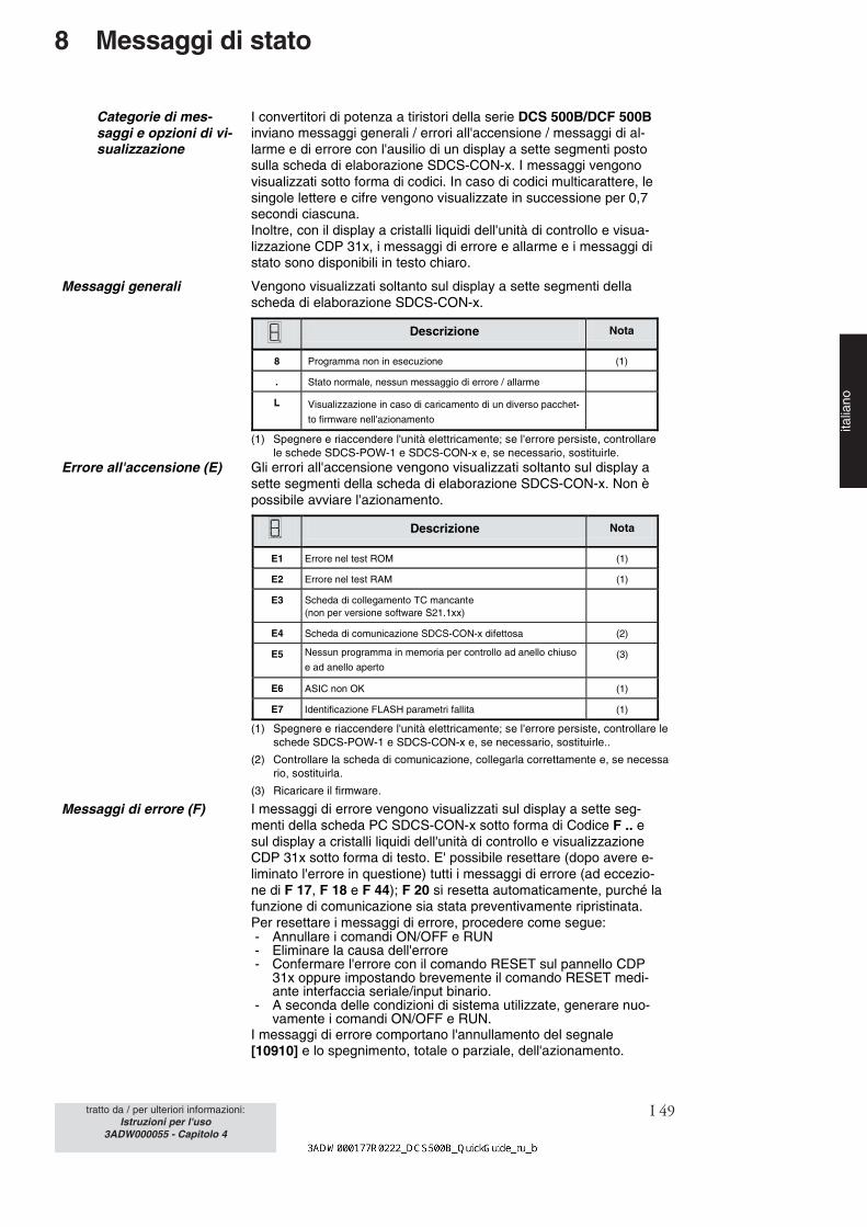
I 49
italia
no
8 Messaggi di stato
Categorie di mes-saggi e opzioni di vi-sualizzazione
I convertitori di potenza a tiristori della serie DCS 500B/DCF 500B inviano messaggi generali / errori all'accensione / messaggi di al-larme e di errore con l'ausilio di un display a sette segmenti posto sulla scheda di elaborazione SDCS-CON-x. I messaggi vengono visualizzati sotto forma di codici. In caso di codici multicarattere, le singole lettere e cifre vengono visualizzate in successione per 0,7 secondi ciascuna. Inoltre, con il display a cristalli liquidi dell'unità di controllo e visua-lizzazione CDP 31x, i messaggi di errore e allarme e i messaggi di stato sono disponibili in testo chiaro.
Messaggi generali
Vengono visualizzati soltanto sul display a sette segmenti della scheda di elaborazione SDCS-CON-x.
Descrizione Nota
8 Programma non in esecuzione (1)
. Stato normale, nessun messaggio di errore / allarme
L Visualizzazione in caso di caricamento di un diverso pacchet-
to firmware nell'azionamento
(1) Spegnere e riaccendere l'unità elettricamente; se l'errore persiste, controllare le schede SDCS-POW-1 e SDCS-CON-x e, se necessario, sostituirle.
Errore all'accensione (E)
Gli errori all'accensione vengono visualizzati soltanto sul display a sette segmenti della scheda di elaborazione SDCS-CON-x. Non è possibile avviare l'azionamento.
Descrizione Nota
E1 Errore nel test ROM (1)
E2 Errore nel test RAM (1)
E3 Scheda di collegamento TC mancante (non per versione software S21.1xx)
E4 Scheda di comunicazione SDCS-CON-x difettosa (2)
E5 Nessun programma in memoria per controllo ad anello chiuso
e ad anello aperto (3)
E6 ASIC non OK (1)
E7 Identificazione FLASH parametri fallita (1)
(1) Spegnere e riaccendere l'unità elettricamente; se l'errore persiste, controllare le schede SDCS-POW-1 e SDCS-CON-x e, se necessario, sostituirle..
(2) Controllare la scheda di comunicazione, collegarla correttamente e, se necessa-rio, sostituirla.
(3) Ricaricare il firmware. Messaggi di errore (F)
I messaggi di errore vengono visualizzati sul display a sette seg-menti della scheda PC SDCS-CON-x sotto forma di Codice F .. e sul display a cristalli liquidi dell'unità di controllo e visualizzazione CDP 31x sotto forma di testo. E' possibile resettare (dopo avere e-liminato l'errore in questione) tutti i messaggi di errore (ad eccezio-ne di F 17, F 18 e F 44); F 20 si resetta automaticamente, purché la funzione di comunicazione sia stata preventivamente ripristinata. Per resettare i messaggi di errore, procedere come segue: - Annullare i comandi ON/OFF e RUN - Eliminare la causa dell'errore - Confermare l'errore con il comando RESET sul pannello CDP
31x oppure impostando brevemente il comando RESET medi-ante interfaccia seriale/input binario.
- A seconda delle condizioni di sistema utilizzate, generare nuo-vamente i comandi ON/OFF e RUN.
I messaggi di errore comportano l'annullamento del segnale [10910] e lo spegnimento, totale o parziale, dell'azionamento.
tratto da / per ulteriori informazioni:Istruzioni per l'uso
3ADW000055 - Capitolo 4
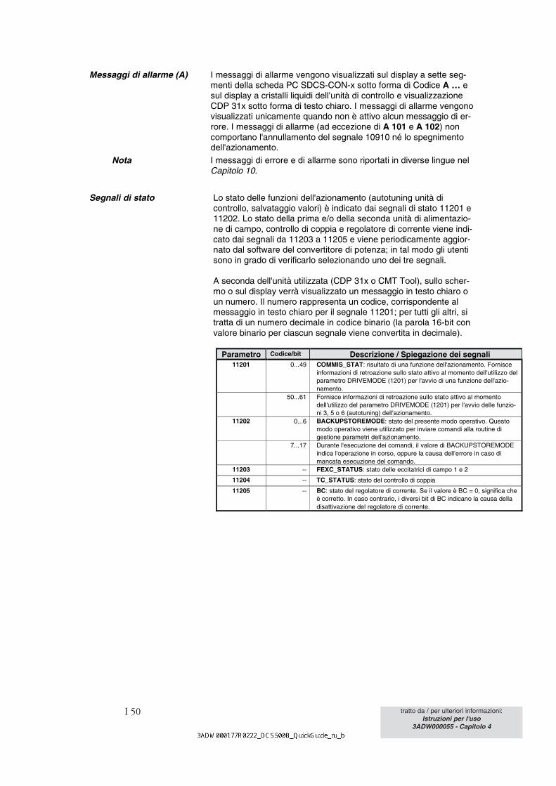
I 50
Messaggi di allarme (A)
I messaggi di allarme vengono visualizzati sul display a sette seg-menti della scheda PC SDCS-CON-x sotto forma di Codice A … e sul display a cristalli liquidi dell'unità di controllo e visualizzazione CDP 31x sotto forma di testo chiaro. I messaggi di allarme vengono visualizzati unicamente quando non è attivo alcun messaggio di er-rore. I messaggi di allarme (ad eccezione di A 101 e A 102) non comportano l'annullamento del segnale 10910 né lo spegnimento dell'azionamento.
Nota I messaggi di errore e di allarme sono riportati in diverse lingue nel Capitolo 10.
Segnali di stato
Lo stato delle funzioni dell'azionamento (autotuning unità di controllo, salvataggio valori) è indicato dai segnali di stato 11201 e 11202. Lo stato della prima e/o della seconda unità di alimentazio-ne di campo, controllo di coppia e regolatore di corrente viene indi-cato dai segnali da 11203 a 11205 e viene periodicamente aggior-nato dal software del convertitore di potenza; in tal modo gli utenti sono in grado di verificarlo selezionando uno dei tre segnali. A seconda dell'unità utilizzata (CDP 31x o CMT Tool), sullo scher-mo o sul display verrà visualizzato un messaggio in testo chiaro o un numero. Il numero rappresenta un codice, corrispondente al messaggio in testo chiaro per il segnale 11201; per tutti gli altri, si tratta di un numero decimale in codice binario (la parola 16-bit con valore binario per ciascun segnale viene convertita in decimale).
Parametro Codice/bit Descrizione / Spiegazione dei segnali
11201 0...49 COMMIS_STAT: risultato di una funzione dell'azionamento. Fornisce informazioni di retroazione sullo stato attivo al momento dell'utilizzo del parametro DRIVEMODE (1201) per l'avvio di una funzione dell'azio-namento.
50...61 Fornisce informazioni di retroazione sullo stato attivo al momento dell'utilizzo del parametro DRIVEMODE (1201) per l'avvio delle funzio-ni 3, 5 o 6 (autotuning) dell'azionamento.
11202 0...6 BACKUPSTOREMODE: stato del presente modo operativo. Questo modo operativo viene utilizzato per inviare comandi alla routine di gestione parametri dell'azionamento.
7...17 Durante l'esecuzione dei comandi, il valore di BACKUPSTOREMODE indica l'operazione in corso, oppure la causa dell'errore in caso di mancata esecuzione del comando.
11203 -- FEXC_STATUS: stato delle eccitatrici di campo 1 e 2
11204 -- TC_STATUS: stato del controllo di coppia
11205 -- BC: stato del regolatore di corrente. Se il valore è BC = 0, significa che è corretto. In caso contrario, i diversi bit di BC indicano la causa della disattivazione del regolatore di corrente.
tratto da / per ulteriori informazioni:Istruzioni per l'uso
3ADW000055 - Capitolo 4
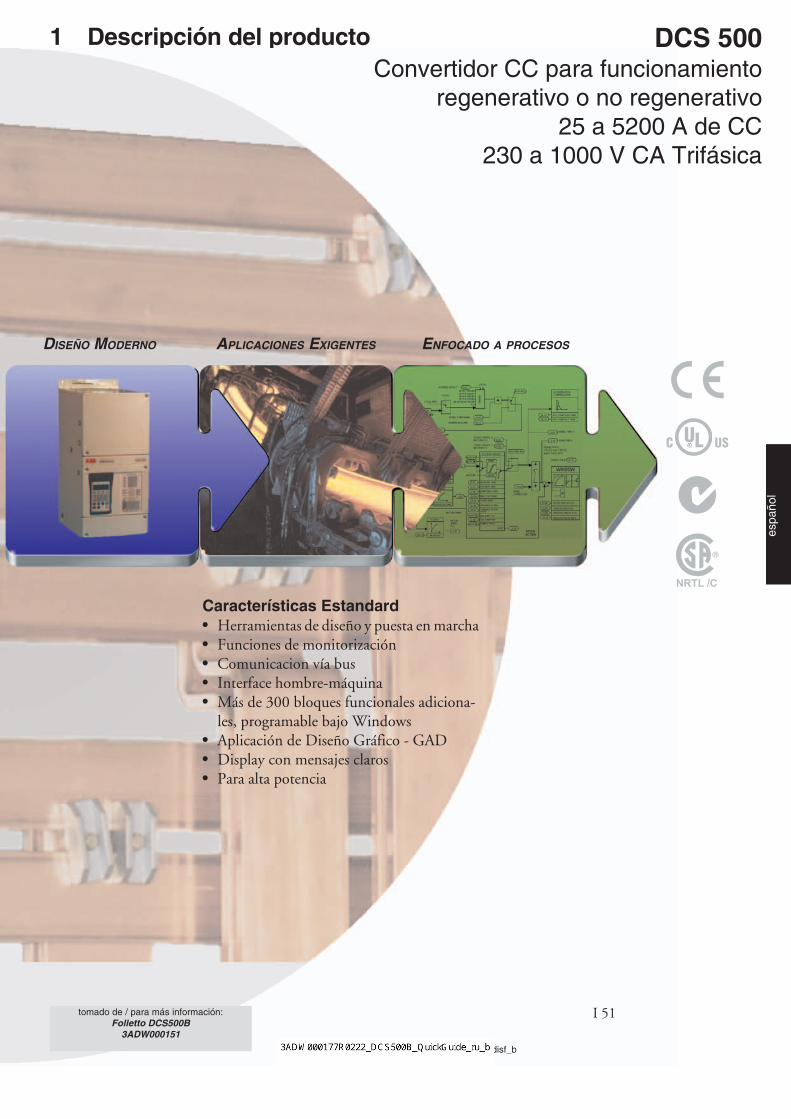
I 51
espa
ñol
1 Descripción del producto
taken from/for further information:DCS500B Flyer
3ADW000151R0401
R
NRTL /C
DCS 500Convertidor CC para funcionamiento
regenerativo o no regenerativo25 a 5200 A de CC
230 a 1000 V CA Trifásica
DISEÑO MODERNO APLICACIONES EXIGENTES ENFOCADO A PROCESOS
Características Estandard• Herramientas de diseño y puesta en marcha• Funciones de monitorización• Comunicacion vía bus• Interface hombre-máquina• Más de 300 bloques funcionales adiciona-
les, programable bajo Windows• Aplicación de Diseño Gráfico - GAD• Display con mensajes claros• Para alta potencia
I 51tomado de / para más información:Folletto DCS500B
3ADW000151
3ADW000177R0200_DCS500B_QuickGuide_edisf_b
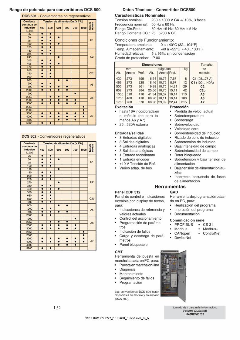
I 52 tomado de / para más información:Folletto DCS500B
3ADW000151
Los convertidores DCS 500 estándisponibles en módulo y en armario(DCA 500).
Rango de potencia para convertidores DCS 500Características NominalesTensión nominal: 230 a 1000 V CA +/-10%, 3 fasesFrecuencia nominal: 50 Hz o 60 HzRango Din.Frec.: 50 Hz: ±5 Hz; 60 Hz: ± 5 HzRango Corriente CC.: 25...5200 A CC.
Condiciones de Funcionamiento:Temperatura ambiente: 0 a +40°C (32...104°F)Temp. Almacenamiento: -40 a +55°C (-40...130°F)Humedad relativa: 5 a 95%, sin condensaciónGrado de protección: IP 00
Excitación• hasta 16A incorporada en
el módulo (no para ta-maños A6 y A7)
• 25...520A externa
Entradas/salidas• 8 Entradas digitales• 8 Salidas digitales• 4 Entradas analógicas• 3 Salidas analógicas• 1 Entrada tacodinamo• 1 Entrada encoder• ±10 V Tensión de Ref.• Varios adap. de bus
Protección• Pérdida de veloc. actual• Sobretemperatura• Sobrecarga• Sobrevelocidad• Velocidad cero• Sobreintensidad de inducido• Rizado de corr. de inducido• Sobretensión de inducido• Baja intensidad de campo• Sobreintensidad de campo• Rotor bloqueado• Sobretensión y baja tensión de
alimentación• Baja tensión de alimentación au-
xiliar• Incorrecta secuencia de fases
de alimentación
Panel CDP 312Panel de control e indicacionesextraible con display de textos,para:• Indicaciones de referencia y
valores actuales• Control del accionamiento• Programación de paráme-
tros• Indicación de fallos• Carga y descarga de pará-
metros• Panel bloqueable
Datos Técnicos - Convertidor DCS500
CMTHerramienta de puesta enmarcha basada en PC, para:• Puesta en marcha on-line• Diagnosis• Mantenimiento• Seguimiento de fallos• Programación
DCS 502 - Convertidores regenerativos
DCS 501 - Convertidores no regenerativos
GADHerramienta de programación basa-da en PC, para:• Realización del programa• Impresión del programa• Documentación
Herramientas
Comunicación serie• PROFIBUS • CS 31• Modbus • Modbus+• CANopen • ControlNet• DeviceNet
Tensión de alimentación [V CA] Corriente contínua de
inducido I
DC [A]
400
500
600
690
790
1000
Tam
año
M
ódu
lo
25 50 75 100 125
C1
180 225 245 315 405 470
C2
610 740 900
C2b
900 1200 1500 2000
A5
1900 2050 2500 3000
A6
2050 2600 3300 4000 4800 5200
A7
Tensión de alimentación [V CA] Corriente contínua de
inducido IDC
[A]
400
500
600
690
790
1000
Tam
año
M
ódu
lo
25 50 75 100 110 140
C1
200 250 270 350 450 520
C2
680 820
1000
C2b
900 1200 1500 2000
A5
1900 2050 2500 3000
A6
2050 2600 3300 4000 4800 5200
A7
Tamañode
módulo
C1 (25...75 A)C1 (100...140A)
C2C2bA5A6A7
Dimensionesmm pulgadas kg
Alt. Ancho Prof. Alt. Ancho Prof.
420 273 195 16,54 10,75 7,67 8469 273 228 18,46 10,75 8,97 12505 273 361 19,88 10,75 14,21 29652 273 384 25,66 10,75 15,11 421050 510 410 41,34 20,07 16,14 1101750 460 410 68,90 18,11 16,14 1801750 760 570 68,90 29,92 22,44 315
I 53
espa
ñol
2 Instrucciones resumidas en CD, notas y publicacionesadicionales
Le estamos agradecidos que haya compradoun convertidor ABB y le queremos dar las gra-cias por confiar en nuestros productos.
Para asegurarnos que continuará satisfechocon nuestro producto, le adjuntamos este folle-to. La intención principal es proporcionarle unabreve descripción de los datos principales delproducto, anotaciones sobre la normativa EMC,aplicaciones típicas, puesta en marcha y señalesde alarma del equipo.
Si requiere mayor información sobre el produc-to, además de esta breve documentación, leproporcionamos un CD ROM (el cual es parteintegrante de este paquete de documentación)en los cinco principales idiomas: inglés, alemán,italiano, español y francés, constando del sigu-iente contenido:
DocumentaciónDocumentación de nuestra serie de productos:• DCS400• DCS500• DCS600
Nuestra documentación está básicamenteestructurada de la siguiente forma:
Descripción del sistemaInformación exhaustiva para la planificación delsistema completo del convertidor.
Datos técnicosInformación detallada, con todos los datos im-portantes de cada uno de los componentes,como dimensiones del módulo, tarjetas elec-trónicas, ventiladores y componentes secunda-rios.
Instrucciones de funcionamientocon toda la información necesaria para la pues-ta en marcha y mantenimiento del convertidorcompleto, de forma detallada.
Software description plus application blocksRequerido únicamente para la programacióndel convertidor, disponible sólo en inglés y no enformato impreso.
Service ManualPara el mantenimiento y reparación de las uni-dades.
Más diversa information on application (p.ej.12 pulsos) y technical accessories, etc.
Requerimientos del sistema parautilizar el CD ROM
• Sistema operativo WINDOWS 98, NT, 2000,XP
• ACROBAT READER 4.0 es suficiente(aunque nosotros recomendamos la versión5.0 - incluida en el CD ROM)
• INTERNET Explorer 5.0 o versión posteriorSi el CD ROM no arrancara automáticamente,haga doble clic en START.HTM
Más soporte
Además le ofrecemos más soporte, ya que sólocuando usted esté satisfecho con nosotros ycon su decisión, nosotros nos sentiremos satis-fechos también.
InternetEn la página ABB
www.abb.com/dc
encontrará abundante información basada en• productos DC• soporte técnico• las últimas actualizaciones• herramientas• descargas, etc.Por favor, no dude en visitarnos.
Contacte con nosotrosSi requiere mayor información, hable con suoficina de ABB Drives más próxima o envíe une-mail a:
Por favor, indíquenos su nombre, empresa,dirección y número de teléfono, e inmediata-mente le informaremos sobre su persona decontacto.
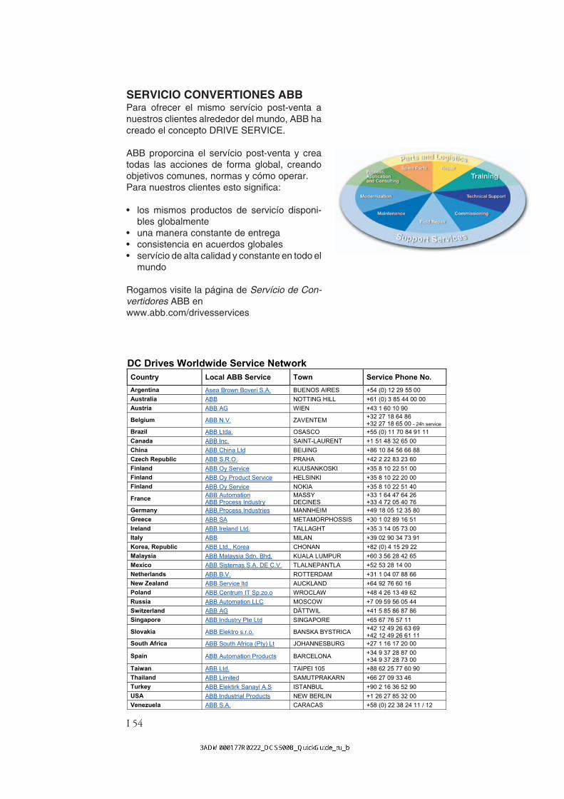
I 54
SERVICIO CONVERTIONES ABBPara ofrecer el mismo servício post-venta anuestros clientes alrededor del mundo, ABB hacreado el concepto DRIVE SERVICE.
ABB proporcina el servício post-venta y creatodas las acciones de forma global, creandoobjetivos comunes, normas y cómo operar.Para nuestros clientes esto significa:
• los mismos productos de servicío disponi-bles globalmente
• una manera constante de entrega• consistencia en acuerdos globales• servício de alta calidad y constante en todo el
mundo
Rogamos visite la página de Servício de Con-vertidores ABB enwww.abb.com/drivesservices
DC Drives Worldwide Service Network Country Local ABB Service Town Service Phone No. Argentina Asea Brown Boveri S.A. BUENOS AIRES +54 (0) 12 29 55 00 Australia ABB NOTTING HILL +61 (0) 3 85 44 00 00 Austria ABB AG WIEN +43 1 60 10 90
Belgium ABB N.V. ZAVENTEM +32 27 18 64 86 +32 27 18 65 00 - 24h service
Brazil ABB Ltda. OSASCO +55 (0) 11 70 84 91 11 Canada ABB Inc. SAINT-LAURENT +1 51 48 32 65 00 China ABB China Ltd BEIJING +86 10 84 56 66 88 Czech Republic ABB S.R.O. PRAHA +42 2 22 83 23 60 Finland ABB Oy Service KUUSANKOSKI +35 8 10 22 51 00 Finland ABB Oy Product Service HELSINKI +35 8 10 22 20 00 Finland ABB Oy Service NOKIA +35 8 10 22 51 40
France ABB Automation ABB Process Industry
MASSY DECINES
+33 1 64 47 64 26 +33 4 72 05 40 76
Germany ABB Process Industries MANNHEIM +49 18 05 12 35 80 Greece ABB SA METAMORPHOSSIS +30 1 02 89 16 51 Ireland ABB Ireland Ltd. TALLAGHT +35 3 14 05 73 00 Italy ABB MILAN +39 02 90 34 73 91 Korea, Republic ABB Ltd., Korea CHONAN +82 (0) 4 15 29 22 Malaysia ABB Malaysia Sdn. Bhd. KUALA LUMPUR +60 3 56 28 42 65 Mexico ABB Sistemas S.A. DE C.V. TLALNEPANTLA +52 53 28 14 00 Netherlands ABB B.V. ROTTERDAM +31 1 04 07 88 66 New Zealand ABB Service ltd AUCKLAND +64 92 76 60 16 Poland ABB Centrum IT Sp.zo.o WROCLAW +48 4 26 13 49 62 Russia ABB Automation LLC MOSCOW +7 09 59 56 05 44 Switzerland ABB AG DÄTTWIL +41 5 85 86 87 86 Singapore ABB Industry Pte Ltd SINGAPORE +65 67 76 57 11
Slovakia ABB Elektro s.r.o. BANSKA BYSTRICA +42 12 49 26 63 69 +42 12 49 26 61 11
South Africa ABB South Africa (Pty) Lt JOHANNESBURG +27 1 16 17 20 00
Spain ABB Automation Products BARCELONA +34 9 37 28 87 00 +34 9 37 28 73 00
Taiwan ABB Ltd. TAIPEI 105 +88 62 25 77 60 90 Thailand ABB Limited SAMUTPRAKARN +66 27 09 33 46 Turkey ABB Elektirk Sanayi A.S ISTANBUL +90 2 16 36 52 90 USA ABB Industrial Products NEW BERLIN +1 26 27 85 32 00 Venezuela ABB S.A. CARACAS +58 (0) 22 38 24 11 / 12
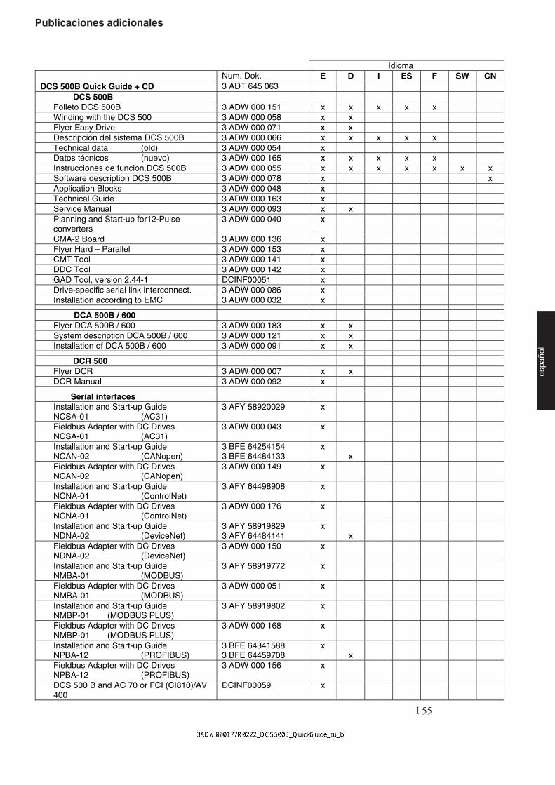
I 55
espa
ñol
Publicaciones adicionales
Idioma Num. Dok. E D I ES F SW CN DCS 500B Quick Guide + CD 3 ADT 645 063 DCS 500B
Folleto DCS 500B 3 ADW 000 151 x x x x x Winding with the DCS 500 3 ADW 000 058 x x Flyer Easy Drive 3 ADW 000 071 x x Descripción del sistema DCS 500B 3 ADW 000 066 x x x x x Technical data (old) 3 ADW 000 054 x Datos técnicos (nuevo) 3 ADW 000 165 x x x x x Instrucciones de funcion.DCS 500B 3 ADW 000 055 x x x x x x x Software description DCS 500B 3 ADW 000 078 x x Application Blocks 3 ADW 000 048 x Technical Guide 3 ADW 000 163 x Service Manual 3 ADW 000 093 x x Planning and Start-up for12-Pulse converters
3 ADW 000 040 x
CMA-2 Board 3 ADW 000 136 x Flyer Hard – Parallel 3 ADW 000 153 x CMT Tool 3 ADW 000 141 x DDC Tool 3 ADW 000 142 x GAD Tool, version 2.44-1 DCINF00051 x Drive-specific serial link interconnect. 3 ADW 000 086 x Installation according to EMC 3 ADW 000 032 x
DCA 500B / 600 Flyer DCA 500B / 600 3 ADW 000 183 x x System description DCA 500B / 600 3 ADW 000 121 x x Installation of DCA 500B / 600 3 ADW 000 091 x x
DCR 500 Flyer DCR 3 ADW 000 007 x x DCR Manual 3 ADW 000 092 x
Serial interfaces Installation and Start-up Guide NCSA-01 (AC31)
3 AFY 58920029 x
Fieldbus Adapter with DC Drives NCSA-01 (AC31)
3 ADW 000 043 x
Installation and Start-up Guide NCAN-02 (CANopen)
3 BFE 64254154 3 BFE 64484133
x x
Fieldbus Adapter with DC Drives NCAN-02 (CANopen)
3 ADW 000 149 x
Installation and Start-up Guide NCNA-01 (ControlNet)
3 AFY 64498908 x
Fieldbus Adapter with DC Drives NCNA-01 (ControlNet)
3 ADW 000 176 x
Installation and Start-up Guide NDNA-02 (DeviceNet)
3 AFY 58919829 3 AFY 64484141
x x
Fieldbus Adapter with DC Drives NDNA-02 (DeviceNet)
3 ADW 000 150 x
Installation and Start-up Guide NMBA-01 (MODBUS)
3 AFY 58919772 x
Fieldbus Adapter with DC Drives NMBA-01 (MODBUS)
3 ADW 000 051 x
Installation and Start-up Guide NMBP-01 (MODBUS PLUS)
3 AFY 58919802 x
Fieldbus Adapter with DC Drives NMBP-01 (MODBUS PLUS)
3 ADW 000 168 x
Installation and Start-up Guide NPBA-12 (PROFIBUS)
3 BFE 64341588 3 BFE 64459708
x x
Fieldbus Adapter with DC Drives NPBA-12 (PROFIBUS)
3 ADW 000 156 x
DCS 500 B and AC 70 or FCI (CI810)/AV 400
DCINF00059 x
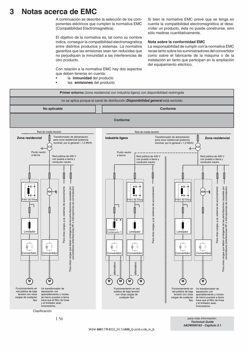
I 56 para más información:Technical Guide
3ADW000163 - Capítulo 2.1
3 Notas acerca de EMC
Clasificación
No aplicable
Primer entorno (zona residencial con industria ligera) con disponibilidad restringida
no se aplica porque el canal de distribución Disponibilidad general está excluido
Conforme
Conforme
A continuación se describe la selección de los com-ponentes eléctricos que cumplen la normativa EMC(Compatibilidad Electromagnética).
El objetivo de la normativa es, tal como su nombreindica, conseguir la compatibilidad electromagnéticaentre distintos productos y sistemas. La normativagarantiza que las emisiones sean tan reducidas queno perjudiquen la inmunidad a las interferencias deotro producto.
Con relación a la normativa EMC hay dos aspectosque deben tenerse en cuenta:• la inmunidad del producto• las emisiones del producto
Si bien la normativa EMC prevé que se tenga encuenta la compatibilidad electromagnética al desa-rrollar un producto, ésta no puede construirse, sinosólo medirse cuantitativamente.
Nota sobre la conformidad EMCLa responsabilidad de cumplir con la normativa EMCrecae tanto sobre los suministradores del convertidorcomo sobre el fabricante de la máquina o de lainstalación en tanto que participan en la ampliacióndel equipamiento eléctrico.
MM
Filtro de línea
Convertidor
Limitador
Transformador de alimentación para zona residencial (potencia nominal: por lo general ≤ 1,2 MVA)
Red pública de 400 V con puesta a tierra y conductor neutro
Red de media tensión
Punto neutro a tierrra
Par
a o
tras
ca
rga
s, p
.ej.
sist
emas
de
acci
onam
ient
o
Un transformador de separación con apantallamiento y núcleo de hierro puestos a tierra hace que el filtro de línea y el limitador sean innecesarios.
Funcionamiento en red pública de baja
tensión con otras cargas de cualquier
tipo
Zona residencial
Pa
ra o
tra
s ca
rgas
qu
e d
eben
pro
tege
rse
de
las
per
turb
acio
nes
cau
sad
as p
or
con
vert
idor
es (
inte
rfer
enc
ias
RF
e in
terr
upci
ones
de
con
mut
aci
ón)
Convertidor
MMMM MM
alte
rnat
ivo
Limitador + Condensator Y
Funcionamiento en red pública de baja tensión
con otras cargas de cualquier tipo
industria ligera
Convertidor Convertidor
alte
rnat
ivo
Limitador
Filtro de línea
Red de media tensión
Transformador de alimentación para zona residencial (potencia nominal: por lo general ≤ 1,2 MVA)
Punto neutro a tierrra Red pública de 400 V
con puesta a tierra y conductor neutro
Pa
ra o
tra
s ca
rgas
, p.
ej.
sist
emas
de
acci
onam
ient
o
Red pública de 400 V con puesta a tierra y conductor neutro
Zona residencial
Filtro de línea
Limitador
Convertidor Convertidor
Funcionamiento en red pública de baja
tensión con otras cargas de cualquier
tipo
Un transformador de separación con apantallamiento y núcleo de hierro puestos a tierra hace que el filtro de línea y el limitador sean innecesarios.
Pa
ra o
tra
s ca
rgas
, p.
ej.
sist
emas
de
acci
onam
ient
o
Par
a o
tras
ca
rga
s qu
e de
ben
pro
tege
rse
de la
s pe
rtu
rba
cion
es c
ausa
das
por
conv
ert
idor
es
(inte
rfer
enci
as
RF
e in
terr
upci
ones
de
conm
utac
ión
)
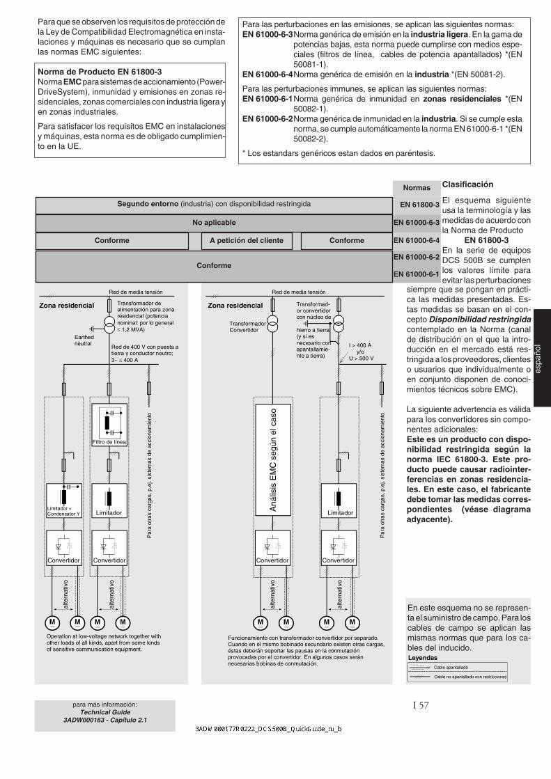
I 57
espa
ñol
para más información:Technical Guide
3ADW000163 - Capítulo 2.1
Para que se observen los requisitos de protección dela Ley de Compatibilidad Electromagnética en insta-laciones y máquinas es necesario que se cumplanlas normas EMC siguientes:
Norma de Producto EN 61800-3Norma EMC para sistemas de accionamiento (Power-DriveSystem), inmunidad y emisiones en zonas re-sidenciales, zonas comerciales con industria ligera yen zonas industriales.
Para satisfacer los requisitos EMC en instalacionesy máquinas, esta norma es de obligado cumplimien-to en la UE.
Clasificación
El esquema siguienteusa la terminología y lasmedidas de acuerdo conla Norma de Producto
EN 61800-3En la serie de equiposDCS 500B se cumplenlos valores límite paraevitar las perturbaciones
siempre que se pongan en prácti-ca las medidas presentadas. Es-tas medidas se basan en el con-cepto Disponibilidad restringidacontemplado en la Norma (canalde distribución en el que la intro-ducción en el mercado está res-tringida a los proveedores, clienteso usuarios que individualmente oen conjunto disponen de conoci-mientos técnicos sobre EMC).
La siguiente advertencia es válidapara los convertidores sin compo-nentes adicionales:Este es un producto con dispo-nibilidad restringida según lanorma IEC 61800-3. Este pro-ducto puede causar radiointer-ferencias en zonas residencia-les. En este caso, el fabricantedebe tomar las medidas corres-pondientes (véase diagramaadyacente).
MMMM
Red de 400 V con puesta a tierra y conductor neutro; 3~ ≤ 400 A
Operation at low-voltage network together with other loads of all kinds, apart from some kinds of sensitive communication equipment.
Earthed neutral
Zona residencial
Red de media tensión
Transformador de alimentación para zona residencial (potencia nominal: por lo general ≤ 1,2 MVA)
Par
a o
tras
ca
rga
s, p
.ej.
sist
emas
de
acci
onam
ient
o
alte
rnat
ivo
alte
rnat
ivo
Convertidor Convertidor
Limitador + Condensator Y Limitador
Filtro de línea
MMMM
Transformador Convertidor
Aná
lisis
EM
C s
egún
el c
aso
Transformad-or convertidor con núcleo de
hierro a tierra (y si es necesario con apantallamie-nto a tierra)
I > 400 A y/o U > 500 V
Funcionamiento con transformador convertidor por separado. Cuando en el mismo bobinado secundario existen otras cargas, éstas deberán soportar las pausas en la conmutación provocadas por el convertidor. En algunos casos serán necesarias bobinas de conmutación.
Zona residencial
Red de media tensión
Convertidor Convertidor
alte
rnat
ivo
alte
rnat
ivo
Par
a o
tras
ca
rga
s, p
.ej.
sist
emas
de
acci
onam
ient
o
Limitador
Leyendas
Cable no apantallado con restricciones
Cable apantallado
En este esquema no se represen-ta el suministro de campo. Para loscables de campo se aplican lasmismas normas que para los ca-bles del inducido.
Para las perturbaciones en las emisiones, se aplican las siguientes normas:EN 61000-6-3Norma genérica de emisión en la industria ligera. En la gama de
potencias bajas, esta norma puede cumplirse con medios espe-ciales (filtros de línea, cables de potencia apantallados) *(EN50081-1).
EN 61000-6-4Norma genérica de emisión en la industria *(EN 50081-2).
Para las perturbaciones immunes, se aplican las siguientes normas:EN 61000-6-1Norma genérica de inmunidad en zonas residenciales *(EN
50082-1).EN 61000-6-2Norma genérica de inmunidad en la industria. Si se cumple esta
norma, se cumple automáticamente la norma EN 61000-6-1 *(EN50082-2).
* Los estandars genéricos estan dados en paréntesis.
EN 61800-3
EN 61000-6-3
EN 61000-6-4
EN 61000-6-2
EN 61000-6-1
Conforme
Conforme
Segundo entorno (industria) con disponibilidad restringida
A petición del cliente Conforme
No aplicable
Normas
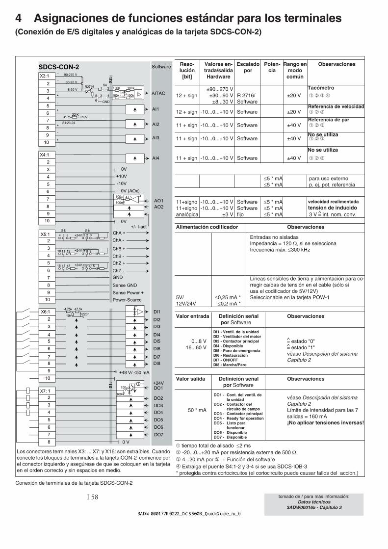
I 58 tomado de / para más información:Datos técnicos
3ADW000165 - Capítulo 3
4 Asignaciones de funciones estándar para los terminales(Conexión de E/S digitales y analógicas de la tarjeta SDCS-CON-2)
Conexión de terminales de la tarjeta SDCS-CON-2
Reso- Valores en- Escalado Poten- Rango en Observacioneslución trada/salida por cia modo[bit] Hardware común
±90...270 V12 + sign ±30...90 V R 2716/ ±20 V ➀ ➁ ➂ ➃
±8...30 V Software
12 + sign -10...0...+10 V Software ±20 V ➀ ➁ ➂
11 + sign -10...0...+10 V Software ±40 V ➀ ➁ ➂
11 + sign -10...0...+10 V Software ±40 V ➀ ➁ ➂
11 + sign -10...0...+10 V Software ±40 V ➀ ➁ ➂
≤5 * mA para uso externo≤5 * mA p. ej. pot. referencia
11+signo -10...0...+10 V Software ≤5 * mA11+signo -10...0...+10 V Software ≤5 * mAanalógica ±3 V fijo ≤5 * mA 3 V = int. nom. conv.
Alimentación codificador Observaciones
Entradas no aisladasImpedancia = 120 Ω, si se seleccionafrecuencia máx. ≤300 kHz
Líneas sensibles de tierra y alimentación para co-rregir caídas de tensión en el cable (sólo siusa el codificador de 5V/12V)
5V/ ≤0,25 mA * Seleccionable en la tarjeta POW-112V/24V ≤0,2 mA *
Valor entrada Definición señal Observacionespor Software
0...8 V = estado "0"16...60 V = estado "1"
véase Descripción del sistemaCapítulo 2
Valor salida Definición señal Observacionespor Software
véase Descripción del sistemaCapítulo 2
50 * mA Límite de intensidad para las 7salidas = 160 mA¡No aplicar tensiones inversas!
➀ tiempo total de alisado ≤2 ms➁ -20...0...+20 mA por resistencia externa de 500 Ω➂ 4...20 mA por ➁ + Función del software➃ Extraiga el puente S4:1-2 y 3-4 si se usa SDCS-IOB-3* protegida contra cortocircuitos (el cortocircuito puede causar fallos del accion.)
Los conectores terminales X3: ... X7: y X16: son extraíbles. Cuandoconecte los bloques de terminales a la tarjeta CON-2 comience porel conector izquierdo y asegúrese de que se coloquen en la tarjetaen el orden correcto y sin espacios en medio.
X2:
X1:
AITAC
90-270 V
30-90 V
8-30 V
+24V
AI4
ChA +ChA -
ChB +ChB -ChZ +ChZ -GND
0 V
R2716
+10V
S1:23-24
100µ
+48 V/ ≤50 mA
100k1n1n
100n
100k
100k 100k
Power-Source
Sense GNDSense Power +
0V
AI2
AI3
AI1-
+
-
+
-
+
-
-
-
+
AO1AO2
+/- I-act
47.5100µ
100n
0V (AOx)
+10V0V
-10V
DI1
DI2DI3
DI4DI5DI6
DI7DI8
47.5k220n10k
4.75k
DO4DO5
DO7
DO1
DO2DO3
DO6
22 K
345
87
67
9
X6:1 2 3
4 5 6
7 8
10
4 5
7
1 2 3
6
4
23
65
910
89
10
2
45
7
23
6
89
10
8
X3:1
X4:1
X5:1
X7:
SDCS-CON-2 Software
+24V 7 8 910 11 12
+24V 13141516 17 18
+24V4 5 6S1:
1 2 3S1:
GND
1 2
3 456
S4
Referencia de velocidad
Tacómetro
Referencia de par
No se utiliza
No se utiliza
velocidad realimentadatension de inducido
DI1 - Ventil. de la unidadDI2 - Ventilador del motorDI3 - Contactor principalDI4 - DisponibleDI5 - Paro de emergenciaDI6 - RestauraciónDI7 - ON/OFFDI8 - Marcha/Paro
DO1 - Cont. del ventil. dela unidad
DO2 - Contactor delcircuito de campo
DO3 - Contactor principalDO4 - Ready for operationDO5 - Listo para
funcionarDO6 - DisponibleDO7 - Disponible
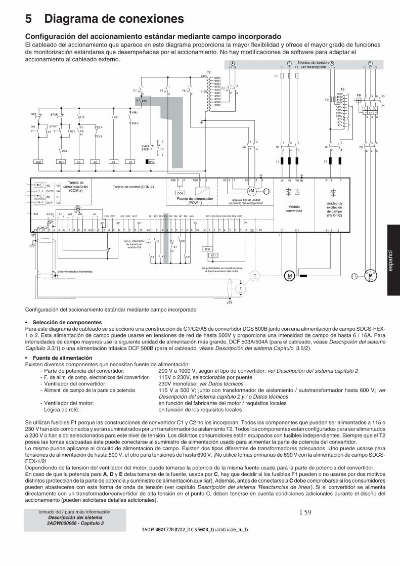
I 59
espa
ñol
5 Diagrama de conexiones
tomado de / para más información:Descripción del sistema3ADW000066 - Capítulo 3
Configuración del accionamiento estándar mediante campo incorporado
Configuración del accionamiento estándar mediante campo incorporadoEl cableado del accionamiento que aparece en este diagrama proporciona la mayor flexibilidad y ofrece el mayor grado de funcionesde monitorización estándares que desempeñadas por el accionamiento. No hay modificaciones de software para adaptar elaccionamiento al cableado externo.
• Selección de componentesPara este diagrama de cableado se seleccionó una construcción de C1/C2/A5 de convertidor DCS 500B junto con una alimentación de campo SDCS-FEX-1 o 2. Esta alimentación de campo puede usarse en tensiones de red de hasta 500V y proporciona una intensidad de campo de hasta 6 / 16A. Paraintensidades de campo mayores use la siguiente unidad de alimentación más grande, DCF 503A/504A (para el cableado, véase Descripción del sistemaCapítulo 3.3/1) o una alimentación trifásica DCF 500B (para el cableado, véase Descripción del sistema Capítulo 3.5/2).
• Fuente de alimentaciónExisten diversos componentes que necesitan fuente de alimentación:
- Parte de potencia del convertidor: 200 V a 1000 V, según el tipo de convertidor; ver Descripción del sistema capítulo 2- F. de alim. de comp. electrónicos del convertidor: 115V o 230V, seleccionable por puente- Ventilador del convertidor: 230V monofase; ver Datos técnicos- Aliment. de campo de la parte de potencia 115 V a 500 V; junto con transformador de aislamiento / autotransformador hasta 600 V; ver
Descripción del sistema capítulo 2 y / o Datos técnicos- Ventilador del motor: en función del fabricante del motor / requisitos locales- Lógica de relé: en función de los requisitos locales
Se utilizan fusibles F1 porque las construcciones de convertidor C1 y C2 no los incorporan. Todos los componentes que pueden ser alimentados a 115 o230 V han sido combinados y serán suministrados por un transformador de aislamiento T2. Todos los componentes están configurados para ser alimentadosa 230 V o han sido seleccionados para este nivel de tensión. Los distintos consumidores están equipados con fusibles independientes. Siempre que el T2posea las tomas adecuadas éste puede conectarse al suministro de alimentación usado para alimentar la parte de potencia del convertidor.Lo mismo puede aplicarse al circuito de alimentación de campo. Existen dos tipos diferentes de transformadores adecuados. Uno puede usarse paratensiones de alimentación de hasta 500 V, el otro para tensiones de hasta 690 V. ¡No utilice tomas primarias de 690 V con la alimentación de campo SDCS-FEX-1/2!Dependiendo de la tensión del ventilador del motor, puede tomarse la potencia de la misma fuente usada para la parte de potencia del convertidor.En caso de que la potencia para A, D y E deba tomarse de la fuente, usada por C, hay que decidir si los fusibles F1 pueden o no usarse por dos motivosdistintos (protección de la parte de potencia y suministro de alimentación auxiliar). Además, antes de conectarse a C debe comprobarse si los consumidorespueden abastecerse con esta forma de onda de tensión (ver capítulo Descripción del sistema 'Reactancias de línea'). Si el convertidor se alimentadirectamente con un transformador/convertidor de alta tensión en el punto C, deben tenerse en cuenta condiciones adicionales durante el diseño delaccionamiento (pueden solicitarse detalles adicionales).
IN3
OUT3
IN1
OUT1
V5
V6
V1
V2
X96:
DO8
1 2 X99: 1 2 X2: 4 5 X2: 1 2 3 U1 W1V1 PE
K1 F6
K20
K21K20 K3 K1
X96:1
X96:2
L1 L2 L3
F1
F3
K31 3
2 4
M~
T3F23
4
1
2
T2690V660V600V575V525V500V450V415V400V380V
115V
230V
K15
K15
S1
1
2
K6 K8
X2:4
X2:5
K11K10
K21
500V460V415V400V
365V350V265V250V90V60V30V
X33
C 1 D 1
AITAC AI1 AI2 AI3 AI4+10V -10V AO1 AO2 IACT DI1 DI2 DI3 DI4 DI5 DI6 DI7 DI8 +48V DO1 DO2 DO3 DO4 DO5 DO6 DO7_ _ _ _ _+ + + + +
T
T M
0V0V0V0V0V
X3: 1 2 3 4 5 6 7 8 9 10 X4: 1 2 3 4 5 6 7 8 9 10 X6: 1 2 3 4 5 6 7 8 9 10 X7: 1 2 3 4 5 6 7 8 1...10X5:+ _
+
_
K1
K20
K21
K6
K8
1
2S1
K11
K10
S4
5 6
2 4 6
1 3 5K6
F51
2F8
1
2F7
1
2
2
1
4
3
6
5F6
I > I > I >
13
14
UV
WM3~
K11 3 5
2 4 6
L1
1
2
3
4K8
13
14
X1: 1 7
L3
X1: 5 3+ _
L1 N L1 N L1 L2 L3A C D E
Tarjeta de comunicaciones
(COM-x)Tarjeta de control (CON-2)
Fuente de alimentación(POW-1)
Módulo convertidor
Unidad de excitación de campo (FEX-1/2)
ON
OFF
según el tipo de unidades posible otra configuración
las polaridades se muestran para el funcionamiento del motorsi hay terminales intermedios
por ej. interruptor de presión en
módulo C4
Niveles de tensionver descripción
STOP
START
EMER.STOP
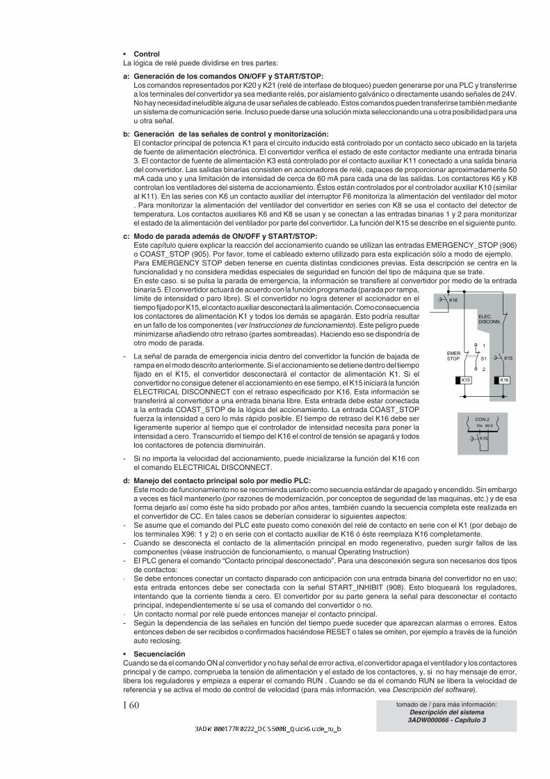
I 60 tomado de / para más información:Descripción del sistema3ADW000066 - Capítulo 3
• ControlLa lógica de relé puede dividirse en tres partes:
a: Generación de los comandos ON/OFF y START/STOP:Los comandos representados por K20 y K21 (relé de interfase de bloqueo) pueden generarse por una PLC y transferirsea los terminales del convertidor ya sea mediante relés, por aislamiento galvánico o directamente usando señales de 24V.No hay necesidad ineludible alguna de usar señales de cableado. Estos comandos pueden transferirse también medianteun sistema de comunicación serie. Incluso puede darse una solución mixta seleccionando una u otra posibilidad para unau otra señal.
b: Generación de las señales de control y monitorización:El contactor principal de potencia K1 para el circuito inducido está controlado por un contacto seco ubicado en la tarjetade fuente de alimentación electrónica. El convertidor verifica el estado de este contactor mediante una entrada binaria3. El contactor de fuente de alimentación K3 está controlado por el contacto auxiliar K11 conectado a una salida binariadel convertidor. Las salidas binarias consisten en accionadores de relé, capaces de proporcionar aproximadamente 50mA cada uno y una limitación de intensidad de cerca de 60 mA para cada una de las salidas. Los contactores K6 y K8controlan los ventiladores del sistema de accionamiento. Éstos están controlados por el controlador auxiliar K10 (similaral K11). En las series con K6 un contacto auxiliar del interruptor F6 monitoriza la alimentación del ventilador del motor. Para monitorizar la alimentación del ventilador del convertidor en series con K8 se usa el contacto del detector detemperatura. Los contactos auxiliares K6 and K8 se usan y se conectan a las entradas binarias 1 y 2 para monitorizarel estado de la alimentación del ventilador por parte del convertidor. La función del K15 se describe en el siguiente punto.
c: Modo de parada además de ON/OFF y START/STOP:Este capítulo quiere explicar la reacción del accionamiento cuando se utilizan las entradas EMERGENCY_STOP (906)o COAST_STOP (905). Por favor, tome el cableado externo utilizado para esta explicación sólo a modo de ejemplo.Para EMERGENCY STOP deben tenerse en cuenta distintas condiciones previas. Esta descripción se centra en lafuncionalidad y no considera medidas especiales de seguridad en función del tipo de máquina que se trate.En este caso. si se pulsa la parada de emergencia, la información se transfiere al convertidor por medio de la entradabinaria 5. El convertidor actuará de acuerdo con la función programada (parada por rampa,límite de intensidad o paro libre). Si el convertidor no logra detener el accionador en eltiempo fijado por K15, el contacto auxiliar desconectará la alimentación. Como consecuencialos contactores de alimentación K1 y todos los demás se apagarán. Esto podría resultaren un fallo de los componentes (ver Instrucciones de funcionamiento). Este peligro puedeminimizarse añadiendo otro retraso (partes sombreadas). Haciendo eso se dispondría deotro modo de parada.
- La señal de parada de emergencia inicia dentro del convertidor la función de bajada derampa en el modo descrito anteriormente. Si el accionamiento se detiene dentro del tiempofijado en el K15, el convertidor desconectará el contactor de alimentación K1. Si elconvertidor no consigue detener el accionamiento en ese tiempo, el K15 iniciará la funciónELECTRICAL DISCONNECT con el retraso especificado por K16. Esta información setransferirá al convertidor a una entrada binaria libre. Esta entrada debe estar conectadaa la entrada COAST_STOP de la lógica del accionamiento. La entrada COAST_STOPfuerza la intensidad a cero lo más rápido posible. El tiempo de retraso del K16 debe serligeramente superior al tiempo que el controlador de intensidad necesita para poner laintensidad a cero. Transcurrido el tiempo del K16 el control de tensión se apagará y todoslos contactores de potencia disminuirán.
- Si no importa la velocidad del accionamiento, puede inicializarse la función del K16 conel comando ELECTRICAL DISCONNECT.
d: Manejo del contacto principal solo por medio PLC:Este modo de funcionamiento no se recomienda usarlo como secuencia estándar de apagado y encendido. Sin embargoa veces es fácil mantenerlo (por razones de modernización, por conceptos de seguridad de las maquinas, etc.) y de esaforma dejarlo así como éste ha sido probado por años antes, también cuando la secuencia completa este realizada enel convertidor de CC. En tales casos se deberían considerar lo siguientes aspectos:
- Se asume que el comando del PLC este puesto como conexión del relé de contacto en serie con el K1 (por debajo delos terminales X96: 1 y 2) o en serie con el contacto auxiliar de K16 ó éste reemplaza K16 completamente.
- Cuando se desconecta el contacto de la alimentación principal en modo regenerativo, pueden surgir fallos de lascomponentes (véase instrucción de funcionamiento, o manual Operating Instruction)
- El PLC genera el comando “Contacto principal desconectado”. Para una desconexión segura son necesarios dos tiposde contactos:
· Se debe entonces conectar un contacto disparado con anticipación con una entrada binaria del convertidor no en uso;esta entrada entonces debe ser conectada con la señal START_INHIBIT (908). Esto bloqueará los reguladores,intentando que la corriente tienda a cero. El convertidor por su parte genera la señal para desconectar el contactoprincipal, independientemente sí se usa el comando del convertidor o no.
· Un contacto normal por relè puede entonces manejar el contacto principal.- Según la dependencia de las señales en función del tiempo puede suceder que aparezcan alarmas o errores. Estos
entonces deben de ser recibidos o confirmados haciéndose RESET o tales se omiten, por ejemplo a través de la funciónauto reclosing.
• SecuenciaciónCuando se da el comando ON al convertidor y no hay señal de error activa, el convertidor apaga el ventilador y los contactoresprincipal y de campo, comprueba la tensión de alimentación y el estado de los contactores, y, si no hay mensaje de error,libera los reguladores y empieza a esperar el comando RUN . Cuando se da el comando RUN se libera la velocidad dereferencia y se activa el modo de control de velocidad (para más información, vea Descripción del software).
EMER.STOP
K16
K15 K16
K15
ELEC.DISCONN.
DIx
K15
X6:9CON-2
S1
1
2
I 61
espa
ñol
1. GeneralDurante el servicio los convertidores de accionamiento pueden -según su tipo de protección - tener partes conduciendocorrientes, desnudos y dado el caso también partes móviles yrotantes, asi como superficies calientes.
Al quitar inadmisiblemente el cubrimiento necesario, aplicacióninadecuada, falso montaje o manejo hay el peligro de gravesdaños personales y materiales.
Otras informaciones son indicadas en la documentación.
Todos los trabajos para el transporte, la conexión, la puesta enfuncionamiento y el mantenimiento deben ser ejecutados por elresponsable personal cualificado (observar IEC 364 resp.CENELEC HD 384 o DIN VDE 0100 y IEC 664 o DIN VDE 0110y las instrucciones nacionales para la prevención de accidentes).
Personal cualificado para los efectos de estas instrucciones deseguridad fundamentales son personas que son familiarizadoscon la instalación, el montaje, la puesta en funcionamiento y elservicio del producto y que tienen las respectivas cualificacionespara su trabajo.
2. Aplicación de conformidad con las instruccio-nesConvertidores de accionamiento son componentes destinadospara el montaje en instalaciones eléctricas o máquinas.
Al instalarlos en máquinas la puesta en funcionamiento de losconvertidores de accionamiento (es decir el arranque del servicionormal) es prohibida hasta que la conformidad de la máquinacon la directriz de la CE 89/392/CEE (directriz de máquinas) hizoconstado; observar EN 60204.
La puesta en funcionamiento (es decir el arranque del servicionormal) se permite solamente si la directriz de CEE (89/336/CEE) es observada.
Los convertidores de accionamiento responden a lasespecificaciones de la directriz de baja tensión 73/23/CEE. Lasnormas harmonizadas de la serie prEN 50178/DIN VDE 0160junto con la EN 60439-1/VDE 0660 Parte 500 y EN 60146/ VDE0558 se aplican a los convertidores de accionamiento.
Los datos técnicos asi como las instrucciones para la conexiónse indican sobre la placa de carácteristicas y en ladocumentación y deben ser observados estrictamente.
3. Transporte, almacenamientoLas instrucciones para el transporte, el almacenamiento y elmanejo adecuado deben ser observadas.
Las condiciones climáticas deben responder a la prEN 50178.
4. InstalaciónLa instalación y la refrigeración de los aparatos han de serejecutadas según las especificaciones de la documentacióncorrespondiente.
Los convertidores de accionamiento deben ser protegidos contracargas inadmisibles. En particular no se admiten componentesdeformados y/o distancias de aislamiento modificadas resultandodel transporte y del manejo. No tocar los componenteselectrónicos y los contactos.
Los convertidores de accionamiento contienen componenteselectrostáticamente sensitivos, que pueden ser dañados por unmanejo inadecuado. Componentes eléctricos no deben serdañados y deteriorados mecánicamente (posiblementeperjudicial a la salud!).
5. Conexión electricaPara trabajos a los convertidores de accionamiento bajo tensiónse deben observar las vigentes instrucciones nacionales para laprevención de accidentes (p.e. VBG 4).
La instalación eléctrica debe ser ejecutada según lasinstrucciones correspondientes (p.e. secciones transversales delas líneas, fusibles, conexión del conductor de protección). Otrasinformaciones son indicadas en la documentación.
Instrucciones para la instalación conforme a las especificacionesCEM - como pantalla, puesta a tierra, colocación de filtros ycableado - son indicadas en la documentación del convertidor deaccionamiento. También para los convertidores deaccionamiento con una identificación CE estas instruccionessiempre han de ser observadas. El fabricante de la instalación omáquina es responsable para la observación de los valoreslímites fijados por la ley de CEM.
6. FuncionamientoEn caso de necesidad las instalaciones que tienen convertidoresde accionamiento han de ser provistas de dispositivos devigilanica y de protección adicionales según las directrices enrazón de la seguridad, por ejemplo la ley sobre equipos técnicos,instrucciones para la prevención de accidentes etc. No sepermiten modificaciones de los convertidores de accionamientomediante del software de control.
Despúes de haber desconectado los convertidores deaccionamiento de la tensión de alimentación no tocarinmediatamente los partes de aparatos bajo tensión y los cablesde potencia a causa de condensadores posiblemente cargados.Observar las respectivas placas indicadoras y identificacionessobre el convertidor de accionamiento.
Durante el servicio todos los cubrimientos y las puertas han dequedarse cerrados.
7. Mantenimiento y conservaciónObservar la documentación del fabricante.
Quédese Vd. estas instrucciones de seguridad!
6 Instrucciones de seguridad
para convertidores de accionamiento DCS / DCF / DCR
(según: directriz de baja tensión 73/23/CEE)
tomado de / para más información:Safety instructions
3ADW000033
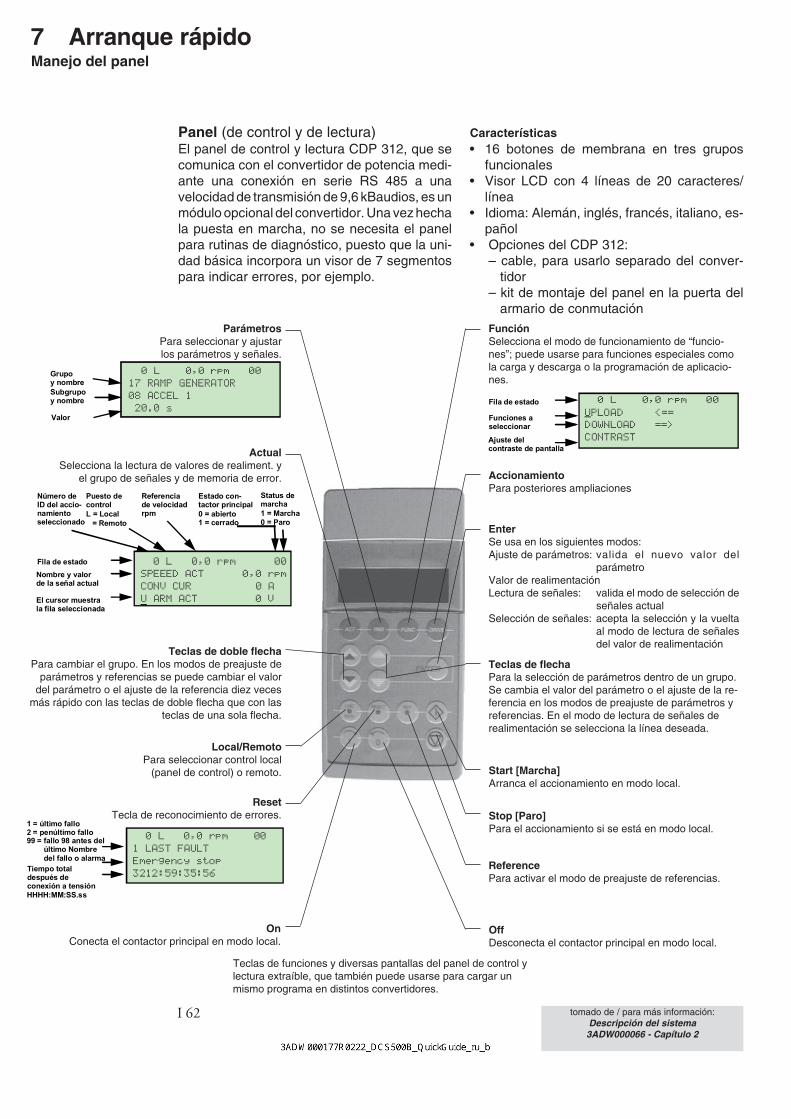
I 62
7 Arranque rápidoManejo del panel
tomado de / para más información:Descripción del sistema3ADW000066 - Capítulo 2
0 L 0,0 rpm 00UPLOAD <==DOWNLOAD ==>CONTRAST
Fila de estado
Funciones aseleccionarAjuste del contraste de pantalla
0 L 0,0 rpm 001 LAST FAULTEmergency stop3212:59:35:56
1 = último fallo2 = penúltimo fallo99 = fallo 98 antes del
último Nombredel fallo o alarma
Tiempo total después deconexión a tensiónHHHH:MM:SS.ss
0 L 0,0 rpm 00 17 RAMP GENERATOR08 ACCEL 1 20.0 s
Grupoy nombreSubgrupoy nombre
Valor
Panel (de control y de lectura)El panel de control y lectura CDP 312, que secomunica con el convertidor de potencia medi-ante una conexión en serie RS 485 a unavelocidad de transmisión de 9,6 kBaudios, es unmódulo opcional del convertidor. Una vez hechala puesta en marcha, no se necesita el panelpara rutinas de diagnóstico, puesto que la uni-dad básica incorpora un visor de 7 segmentospara indicar errores, por ejemplo.
Teclas de funciones y diversas pantallas del panel de control ylectura extraíble, que también puede usarse para cargar unmismo programa en distintos convertidores.
ActualSelecciona la lectura de valores de realiment. y
el grupo de señales y de memoria de error.
ParámetrosPara seleccionar y ajustarlos parámetros y señales.
FunciónSelecciona el modo de funcionamiento de “funcio-nes”; puede usarse para funciones especiales comola carga y descarga o la programación de aplicacio-nes.
AccionamientoPara posteriores ampliaciones
Teclas de doble flechaPara cambiar el grupo. En los modos de preajuste de
parámetros y referencias se puede cambiar el valordel parámetro o el ajuste de la referencia diez veces
más rápido con las teclas de doble flecha que con lasteclas de una sola flecha.
Teclas de flechaPara la selección de parámetros dentro de un grupo.Se cambia el valor del parámetro o el ajuste de la re-ferencia en los modos de preajuste de parámetros yreferencias. En el modo de lectura de señales derealimentación se selecciona la línea deseada.
EnterSe usa en los siguientes modos:Ajuste de parámetros: valida el nuevo valor del
parámetroValor de realimentaciónLectura de señales: valida el modo de selección de
señales actualSelección de señales: acepta la selección y la vuelta
al modo de lectura de señalesdel valor de realimentación
Local/RemotoPara seleccionar control local
(panel de control) o remoto.
ResetTecla de reconocimiento de errores.
ReferencePara activar el modo de preajuste de referencias.
Start [Marcha]Arranca el accionamiento en modo local.
Stop [Paro]Para el accionamiento si se está en modo local.
OnConecta el contactor principal en modo local.
OffDesconecta el contactor principal en modo local.
Características• 16 botones de membrana en tres grupos
funcionales• Visor LCD con 4 líneas de 20 caracteres/
línea• Idioma: Alemán, inglés, francés, italiano, es-
pañol• Opciones del CDP 312:
– cable, para usarlo separado del conver-tidor
– kit de montaje del panel en la puerta delarmario de conmutación
0 L 0,0 rpm 00SPEEED ACT 0,0 rpmCONV CUR 0 AU ARM ACT 0 V
Número de ID del accio-namientoseleccionado
Puesto decontrolL = Local = Remoto
Estado con-tactor principal0 = abierto1 = cerrado
Referencia de velocidadrpm
Status demarcha1 = Marcha0 = Paro
Fila de estadoNombre y valorde la señal actual
El cursor muestrala fila seleccionada
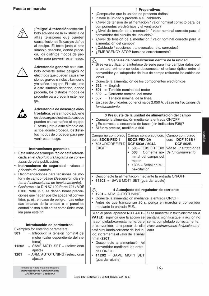
I 63
espa
ñol
Puesta en marcha
tomado de / para más información:Instrucciones de funcionamiento
3ADW000055 - Capítulo 2
¡Peligro! Alta tensión: este sím-bolo advierte de la existencia dealtas tensiones que puedencausar lesiones físicas y/o dañosal equipo. El texto junto a estesímbolo describe, donde proce-da, los distintos modos de pro-ceder para prevenir este riesgo.
Advertencia general: este sím-bolo advierte sobre peligros noeléctricos que pueden causar le-siones graves o incluso la muertey/o daños al equipo. El texto juntoa este símbolo describe, dondeproceda, los distintos modos deproceder para prevenir este ries-go.
Advertencia de descarga elec-trostática: este símbolo adviertede descargas electrostáticas quepueden causar daños al equipo.El texto junto a este símbolo de-scribe, donde proceda, los distin-tos modos de proceder para pre-venir este riesgo.
1 Preparativos• ¡Compruebe que la unidad no presenta daños!• Instale la unidad y proceda a su cableado• ¿Nivel de tensión de alimentación / valor nominal correcto para los
componentes electrónicos y el ventilador?• ¿Nivel de tensión de alimentación / valor nominal correcto para el
convertidor del circuito del inducido?• ¿Nivel de tensión de alimentación / valor nominal correcto para la
alimentación del campo?• ¿Cableado / secciones transversales, etc. correctos?• ¿EMERGENCY STOP funciona correctamente?
2 Señales de normalización dentro de la unidad• Si se va a utilizar una interfase de serie para intercambiar datos con
la unidad, primero se debe desconectar el enlace óptico entre elconvertidor y el adaptador del bus de campo retirando los cables deV260.
• Conecte la alimentación de los componentes electrónicos• 522 = English• 501 = Tensión nominal del motor• 502 = Corriente nominal del motor• 507 = Tensión nominal de la línea• En caso de unidades por encima de 2.050 A: véase Instrucciones de
funcionamiento
3 Preajuste de la unidad de alimentación del campo• Conecte la alimentación mediante la entrada ON/OFF• ¿Es correcta la secuencia de fases (sin indicación F38)?• Si fuera preciso, modifique 506
Campo no controladocon: SDCS-FEX-1• 505 = DIODE FIELD
EXCIT
Campo controlado con:SDCS-FEX-2ADCF 503A / 504A• 505 = FEX2 OR FEX3• 503 = Corriente no-
minal del campo delmotor
• 1305 = Señal de su-bexcitación
Campo controladocon: DCF 501B /
DCF 502Bvéase Instruccionesde funcionamiento
• Desconecte la alimentación mediante la entrada ON/OFF• 11202 = SAVE MOT1 SET (guardar ajuste)
4 Autoajuste del regulador de corriente• 1201 = ARM. AUTOTUNING• Conecte la alimentación mediante la entrada ON/OFF• Antes de que transcurran 20 s, ponga en marcha el convertidor
mediante la entrada RUN.
Si en el panel aparece NOT ACTI-VATED, significa que la acción seha completado correctamente; pareel convertidor; si a pesar de elloestá circulando corriente del induc-ido, incremente el valor de la señalnmin (2201).• Desconecte la alimentación /el
convertidor mediante las entra-das ON/OFF
• 11202 = SAVE MOT1 SET(guardar ajuste)
Si se muestra un texto distinto en lapantalla, significa que la acción nose ha completado correctamente.véase Instrucciones de funcionami-ento
Introducción de parámetrosExamples for entering parameters:501 = Introducir la tensión nominal del
motor (valor dependiente del sis-tema)
11202 = SAVE MOT1 SET = (seleccionarajuste)
1201 = ARM. AUTOTUNING (seleccionarajuste)
Instrucciones generales• Esta rutina de arranque rápido está referen-
ciada en el Capítulo 5 Diagrama de conex-iones de esta publicación.
• Instrucciones de seguridad - véase elprincipio del capítulo.
• Recomendaciones para tensiones del mo-tor y de campo (véase Descripción del sis-tema / Instrucciones de funcionamiento).
• Conforme a la DIN 57 100 Parte 727 / VDE0100 Parte 727, se deben tomar precau-ciones que hagan posible apagar el conver-tidor, p. ej., en caso de peligro. ¡Las entra-das binarias de la unidad o el panel decontrol no son suficientes como única med-ida para este fin!
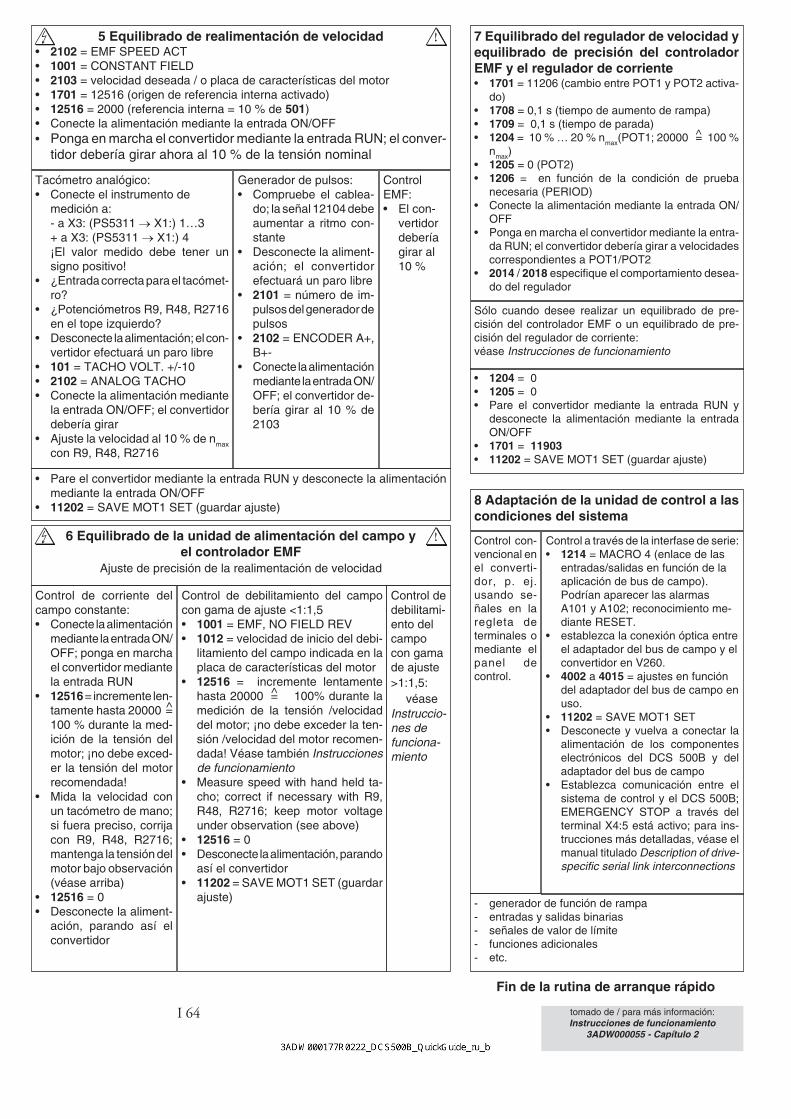
I 64 tomado de / para más información:Instrucciones de funcionamiento
3ADW000055 - Capítulo 2
5 Equilibrado de realimentación de velocidad• 2102 = EMF SPEED ACT• 1001 = CONSTANT FIELD• 2103 = velocidad deseada / o placa de características del motor• 1701 = 12516 (origen de referencia interna activado)• 12516 = 2000 (referencia interna = 10 % de 501)• Conecte la alimentación mediante la entrada ON/OFF• Ponga en marcha el convertidor mediante la entrada RUN; el conver-
tidor debería girar ahora al 10 % de la tensión nominal
Tacómetro analógico:• Conecte el instrumento de
medición a:- a X3: (PS5311 → X1:) 1…3+ a X3: (PS5311 → X1:) 4¡El valor medido debe tener unsigno positivo!
• ¿Entrada correcta para el tacómet-ro?
• ¿Potenciómetros R9, R48, R2716en el tope izquierdo?
• Desconecte la alimentación; el con-vertidor efectuará un paro libre
• 101 = TACHO VOLT. +/-10• 2102 = ANALOG TACHO• Conecte la alimentación mediante
la entrada ON/OFF; el convertidordebería girar
• Ajuste la velocidad al 10 % de nmax
con R9, R48, R2716
Generador de pulsos:• Compruebe el cablea-
do; la señal 12104 debeaumentar a ritmo con-stante
• Desconecte la aliment-ación; el convertidorefectuará un paro libre
• 2101 = número de im-pulsos del generador depulsos
• 2102 = ENCODER A+,B+-
• Conecte la alimentaciónmediante la entrada ON/OFF; el convertidor de-bería girar al 10 % de2103
ControlEMF:• El con-
vertidordeberíagirar al10 %
• Pare el convertidor mediante la entrada RUN y desconecte la alimentaciónmediante la entrada ON/OFF
• 11202 = SAVE MOT1 SET (guardar ajuste)
7 Equilibrado del regulador de velocidad yequilibrado de precisión del controladorEMF y el regulador de corriente• 1701 = 11206 (cambio entre POT1 y POT2 activa-
do)• 1708 = 0,1 s (tiempo de aumento de rampa)• 1709 = 0,1 s (tiempo de parada)• 1204 = 10 % … 20 % nmax(POT1; 20000 = 100 %
nmax)• 1205 = 0 (POT2)• 1206 = en función de la condición de prueba
necesaria (PERIOD)• Conecte la alimentación mediante la entrada ON/
OFF• Ponga en marcha el convertidor mediante la entra-
da RUN; el convertidor debería girar a velocidadescorrespondientes a POT1/POT2
• 2014 / 2018 especifique el comportamiento desea-do del regulador
Sólo cuando desee realizar un equilibrado de pre-cisión del controlador EMF o un equilibrado de pre-cisión del regulador de corriente:véase Instrucciones de funcionamiento
• 1204 = 0• 1205 = 0• Pare el convertidor mediante la entrada RUN y
desconecte la alimentación mediante la entradaON/OFF
• 1701 = 11903• 11202 = SAVE MOT1 SET (guardar ajuste)
8 Adaptación de la unidad de control a lascondiciones del sistema
6 Equilibrado de la unidad de alimentación del campo yel controlador EMF
Ajuste de precisión de la realimentación de velocidad
Control de corriente delcampo constante:• Conecte la alimentación
mediante la entrada ON/OFF; ponga en marchael convertidor mediantela entrada RUN
• 12516 = incremente len-tamente hasta 20000 =100 % durante la med-ición de la tensión delmotor; ¡no debe exced-er la tensión del motorrecomendada!
• Mida la velocidad conun tacómetro de mano;si fuera preciso, corrijacon R9, R48, R2716;mantenga la tensión delmotor bajo observación(véase arriba)
• 12516 = 0• Desconecte la aliment-
ación, parando así elconvertidor
Control de debilitamiento del campocon gama de ajuste <1:1,5• 1001 = EMF, NO FIELD REV• 1012 = velocidad de inicio del debi-
litamiento del campo indicada en laplaca de características del motor
• 12516 = incremente lentamentehasta 20000 = 100% durante lamedición de la tensión /velocidaddel motor; ¡no debe exceder la ten-sión /velocidad del motor recomen-dada! Véase también Instruccionesde funcionamiento
• Measure speed with hand held ta-cho; correct if necessary with R9,R48, R2716; keep motor voltageunder observation (see above)
• 12516 = 0• Desconecte la alimentación, parando
así el convertidor• 11202 = SAVE MOT1 SET (guardar
ajuste)
Control dedebilitami-ento delcampocon gamade ajuste>1:1,5:
véaseInstruccio-nes defunciona-miento
Control con-vencional enel converti-dor, p. ej.usando se-ñales en laregleta determinales omediante elpanel decontrol.
Control a través de la interfase de serie:• 1214 = MACRO 4 (enlace de las
entradas/salidas en función de laaplicación de bus de campo).Podrían aparecer las alarmasA101 y A102; reconocimiento me-diante RESET.
• establezca la conexión óptica entreel adaptador del bus de campo y elconvertidor en V260.
• 4002 a 4015 = ajustes en funcióndel adaptador del bus de campo enuso.
• 11202 = SAVE MOT1 SET• Desconecte y vuelva a conectar la
alimentación de los componenteselectrónicos del DCS 500B y deladaptador del bus de campo
• Establezca comunicación entre elsistema de control y el DCS 500B;EMERGENCY STOP a través delterminal X4:5 está activo; para ins-trucciones más detalladas, véase elmanual titulado Description of drive-specific serial link interconnections
- generador de función de rampa- entradas y salidas binarias- señales de valor de límite- funciones adicionales- etc.
Fin de la rutina de arranque rápido
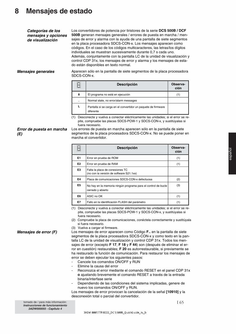
I 65
espa
ñol
8 Mensajes de estado
Categorías de los mensajes y opciones de visualización
Los convertidores de potencia por tiristores de la serie DCS 500B / DCF 500B generan mensajes generales / errores de puesta en marcha / men-sajes de error y alarma con la ayuda de una pantalla de siete segmentos en la placa procesadora SDCS-CON-x. Los mensajes aparecen como códigos. En el caso de los códigos multicaracteres, las letras/los dígitos individuales se muestran sucesivamente durante 0,7 s cada uno. Además, conjuntamente con la pantalla LC de la unidad de visualización y control CDP 31x, los mensajes de error y alarma y los mensajes de esta-do están disponibles en texto normal.
Mensajes generales
Aparecen sólo en la pantalla de siete segmentos de la placa procesadora SDCS-CON-x.
Descripción Observa-
ción
8 El programa no está en ejecución (1)
. Normal state, no error/alarm messages
L Pantalla si se carga en el convertidor un paquete de firmware
diferente
(1) Desconecte y vuelva a conectar eléctricamente las unidades; si el error se re-pite, compruebe las placas SDCS-POW-1 y SDCS-CON-x, y sustitúyalas si fuera necesario.
Error de puesta en marcha (E)
Los errores de puesta en marcha aparecen sólo en la pantalla de siete segmentos de la placa procesadora SDCS-CON-x. No se puede poner en marcha el convertidor.
Descripción Observa-
ción
E1 Error en prueba de ROM (1)
E2 Error en prueba de RAM (1)
E3 Falta la placa de conexiones TC (no con la versión de software S21.1xx)
E4 Placa de comunicaciones SDCS-CON-x defectuosa (2)
E5 No hay en la memoria ningún programa para el control de bucle
cerrado y abierto
(3)
E6 ASIC no OK (1)
E7 Fallo en la identificación FLASH del parámetro (1)
(1) Desconecte y vuelva a conectar eléctricamente las unidades; si el error se re-pite, compruebe las placas SDCS-POW-1 y SDCS-CON-x, y sustitúyalas si fuera necesario.
(2) Compruebe la placa de comunicaciones, conéctela correctamente y sustitúyala si fuera necesario.
(3) Vuelva a cargar el firmware. Mensajes de error (F)
Los mensajes de error aparecen como Código F.. en la pantalla de siete segmentos de la placa procesadora SDCS-CON-x y como texto en la pan-talla LC de la unidad de visualización y control CDP 31x. Todos los men-sajes de error (excepto F 17, F 18 y F 44) son (después de eliminar el er-ror en cuestión) restaurables; F 20 es autorrestaurable, si previamente se ha restaurado la función de comunicación. Para restaurar los mensajes de error se deben ejecutar los siguientes pasos: - Cancele los comandos ON/OFF y RUN - Elimine la causa del error - Reconozca el error mediante el comando RESET en el panel CDP 31x
o ajustando brevemente el comando RESET a través de la entrada binaria/interfase serie
- Dependiendo de las condiciones del sistema implicadas, genere de nuevo los comandos ON/OFF y RUN.
Los mensajes de error provocan la cancelación de la señal [10910] y la desconexión total o parcial del convertidor.
tomado de / para más información:Instrucciones de funcionamiento
3ADW000055 - Capítulo 4
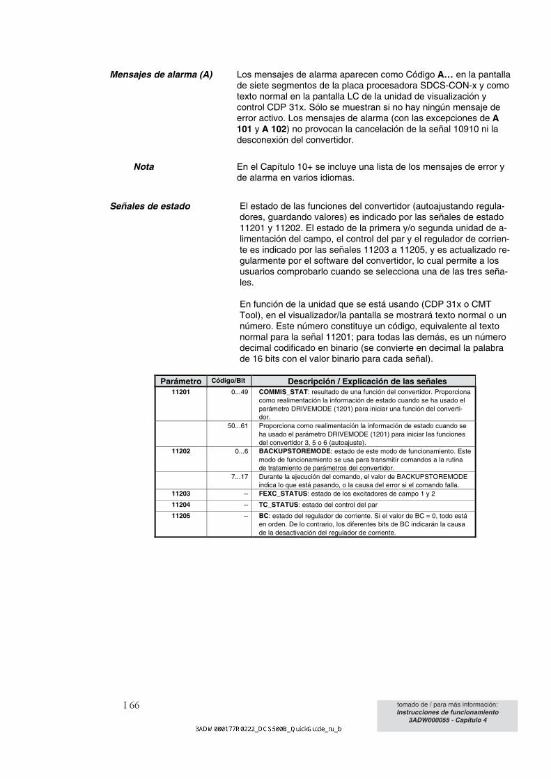
I 66
Mensajes de alarma (A)
Los mensajes de alarma aparecen como Código A… en la pantalla de siete segmentos de la placa procesadora SDCS-CON-x y como texto normal en la pantalla LC de la unidad de visualización y control CDP 31x. Sólo se muestran si no hay ningún mensaje de error activo. Los mensajes de alarma (con las excepciones de A 101 y A 102) no provocan la cancelación de la señal 10910 ni la desconexión del convertidor.
Nota En el Capítulo 10+ se incluye una lista de los mensajes de error y de alarma en varios idiomas.
Señales de estado
El estado de las funciones del convertidor (autoajustando regula-dores, guardando valores) es indicado por las señales de estado 11201 y 11202. El estado de la primera y/o segunda unidad de a-limentación del campo, el control del par y el regulador de corrien-te es indicado por las señales 11203 a 11205, y es actualizado re-gularmente por el software del convertidor, lo cual permite a los usuarios comprobarlo cuando se selecciona una de las tres seña-les. En función de la unidad que se está usando (CDP 31x o CMT Tool), en el visualizador/la pantalla se mostrará texto normal o un número. Este número constituye un código, equivalente al texto normal para la señal 11201; para todas las demás, es un número decimal codificado en binario (se convierte en decimal la palabra de 16 bits con el valor binario para cada señal).
Parámetro Código/Bit Descripción / Explicación de las señales
11201 0...49 COMMIS_STAT: resultado de una función del convertidor. Proporciona como realimentación la información de estado cuando se ha usado el parámetro DRIVEMODE (1201) para iniciar una función del converti-dor.
50...61 Proporciona como realimentación la información de estado cuando se ha usado el parámetro DRIVEMODE (1201) para iniciar las funciones del convertidor 3, 5 o 6 (autoajuste).
11202 0...6 BACKUPSTOREMODE: estado de este modo de funcionamiento. Este modo de funcionamiento se usa para transmitir comandos a la rutina de tratamiento de parámetros del convertidor.
7...17 Durante la ejecución del comando, el valor de BACKUPSTOREMODE indica lo que está pasando, o la causa del error si el comando falla.
11203 -- FEXC_STATUS: estado de los excitadores de campo 1 y 2
11204 -- TC_STATUS: estado del control del par
11205 -- BC: estado del regulador de corriente. Si el valor de BC = 0, todo está en orden. De lo contrario, los diferentes bits de BC indicarán la causa de la desactivación del regulador de corriente.
tomado de / para más información:Instrucciones de funcionamiento
3ADW000055 - Capítulo 4
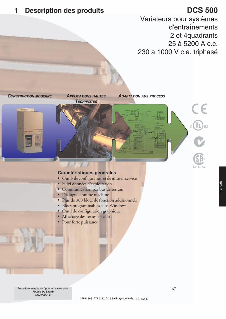
I 67
fran
çais
1 Description des produits DCS 500Variateurs pour systèmes
d'entraînements 2 et 4quadrants25 à 5200 A c.c.
230 a 1000 V c.a. triphasé
CONSTRUCTION MODERNE APPLICATIONS HAUTES
TECHNICITÉS
ADAPTATION AUX PROCESS
Caractéristiques générales• Outils de configuration et de mise en service• Suivi données d'exploitation• Communication par bus de terrain• Dialogue homme machine• Plus de 300 blocs de fonction additionnels• Blocs programmables sous Windows• Outil de configuration graphique• Affichage des textes en clair• Pour forte puissance
I 67
R
NRTL /C
Procédure extraite de / pour en savoir plus:Feuille DCS500B
3ADW000151
3ADW000177R0200_DCS500B_QuickGuide_edisf_b
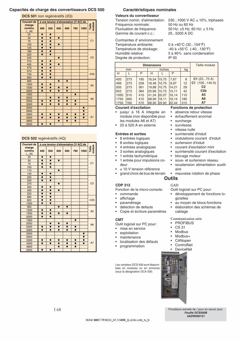
I 68 Procédure extraite de / pour en savoir plus:Feuille DCS500B
3ADW000151
Les variateur DCS 500 sont disponi-bles en modules ou en armoiressous la désignation DCA 500.
Capacités de charge des convertisseurs DCS 500Valeurs du convertisseurTension nomin. d'alimentation: 230...1000 V AC ± 10%, triphaséeFréquence nominale: 50 Hz ou 60 HzFluctuation de fréquence: 50 Hz: ±5 Hz; 60 Hz: ± 5 HzGamme de courant c.c.: 25...5200 A DC
Contraintes d' environnementTempérature ambiante: 0 à +40°C (32...104°F)Température de stockage: -40 à +55°C (-40...130°F)Humidité relative: 5 à 95% sans condensationDegrée de protection: IP 00
Courant d'excitation• jusqu' à 16 A integrée en
module (non disponible pourles modules A6 et A7)
• 25 à 520 A en externe
Entrées et sorties• 8 entrées logiques• 8 sorties logiques• 4 entrées analogiques• 3 sorties analogiques• 1 entrée tachymétrique• 1 entrée pour impulsions co-
deur• ± 10 V tension référence• grand choix de bus de terrain
Fonctions de protection• absence retour vitesse• échauffement anormal• surcharge• survitesse• vitesse nulle• surintensité d'induit• ondulations courant d'induit• surtension d'induit• courant d'excitation mini• surintensité courant d'excitation• blocage moteur• sous- et surtension réseau• soustension alimentation auxili-
aire• mauvaise rotation de phase
CDP 312Fonction de la micro-console:• commande• affichage• paramétrage• détection de defauts• Copie et écriture paramètres
Caractéristiques nominales
CMTOutil logiciel sur PC pour:• mise en service• exploitation• maintenance• localisation des défauts• programmation
DCS 502 regénératifs (4Q)
DCS 501 non regénératifs (2Q)
GADOutil logiciel sur PC pour:• développement de fonctions lo-
gicielles• au moyen de blocs-fonctions• élaboration des schémas de
cablage
Outils
Communication série• PROFIBUS• CS 31• Modbus• Modbus+• CANopen• ControlNet• DeviceNet
à une tension d'alimentation [V AC] de Courant de charge continu I
DC [A]
400
500
600
690
790
1000 T
aille
m
od
ule
25 50 75 100 125
C1
180 225 245 315 405 470
C2
610 740 900
C2b
900 1200 1500 2000
A5
1900 2050 2500 3000
A6
2050 2600 3300 4000 4800 5200
A7
à une tension d'alimentation [V AC] de Courant de charge continu IDC
[A]
400
500
600
690
790
1000 T
aille
m
od
ule
25 50 75 100 110 140
C1
200 250 270 350 450 520
C2
680 820
1000
C2b
900 1200 1500 2000
A5
1900 2050 2500 3000
A6
2050 2600 3300 4000 4800 5200
A7
Taille module
C1 (25...75 A)C1 (100...140 A)
C2C2bA5A6A7
Dimensionsmm inches kg
H L P H L P
420 273 195 16,54 10,75 7,67 8469 273 228 18,46 10,75 8,97 12505 273 361 19,88 10,75 14,21 29652 273 384 25,66 10,75 15,11 421050 510 410 41,34 20,07 16,14 1101750 460 410 68,90 18,11 16,14 1801750 760 570 68,90 29,92 22,44 315
I 69
fran
çais
2 CD des procédures abrégées, informations et autresdocuments
Nous sommes heureux de vous compter parmiles utilisateurs des variateurs c.c. ABB et vousremercions de votre confiance.
Pour conforter votre satisfaction sur le longterme, nous avons élaboré cette brochure quidécrit brièvement les données clés du système,les règles de CEM, les applications types, lesprocédures de mise en route et de diagnostic.
Pour en savoir plus sur le produit, un CD-ROMcomplet (fournie avec cette documentation) in-clut dans les cinq langues principales - anglais,allemand, italien, espagnol et français - leséléments suivants:
Documentation
Documentation de nos gammes de produits:• DCS400• DCS500• DCS600
Structure de base de la documentation techni-que:
Description du systèmeFournit toutes les informations sur le fonctionne-ment du système d'entraînement de puissance.
Caractéristiques techniquesFournit des informations détaillées, avec toutesles spécificités importantes, sur chacun descomposants: dimensions des modules, cartesélectroniques, ventilateurs et auxiliaires.
Manuel d'exploitationDécrit en détail les procédures de mise en routeet de maintenance de l'entraînement complet.
Software Description plus Application blocksManuel de programmation du variateur, unique-ment disponible en anglais et au format électro-nique.
Service ManualPour la maintenance et la réparation des appa-reils.
Plus différents documents sur les applica-tions (ex., montage dodécaphasé, 12 pulses)et accessoires techniques, etc.
Configuration requise pour le CD-ROM
• Système d'exploitation WINDOWS 98, NT,2000, XP
• ACROBAT READER, version 4.0 (nous con-seillons la version 5.0 - incluse sur le CD-ROM)
• INTERNET Explorer 5.0 ou version ultérieureSi le Cd-ROM ne démarre pas automatique-ment, double cliquez sur : START.HTM
Autres sources d'informations
Nous proposons d'autres sources d'informa-tions car votre satisfaction est notre raison d'être.
InternetSur la page d'accueil ABB sous
www.abb.com/dc
vous trouverez une information abondante sur• les produits CC.• les services• les dernières mises à jour• les outils• les téléchargements, etc.N'hésitez pas à consulter notre site.
Nous contacterPour toute information complémentaire, contac-tez votre correspondant ABB Drives ou envoyezun e-mail à:
en précisant votre nom, votre entreprise, votreadresse et votre numéro de téléphone; nousvous répondrons immédiatement en fournis-sant les coordonnées de votre correspondant.
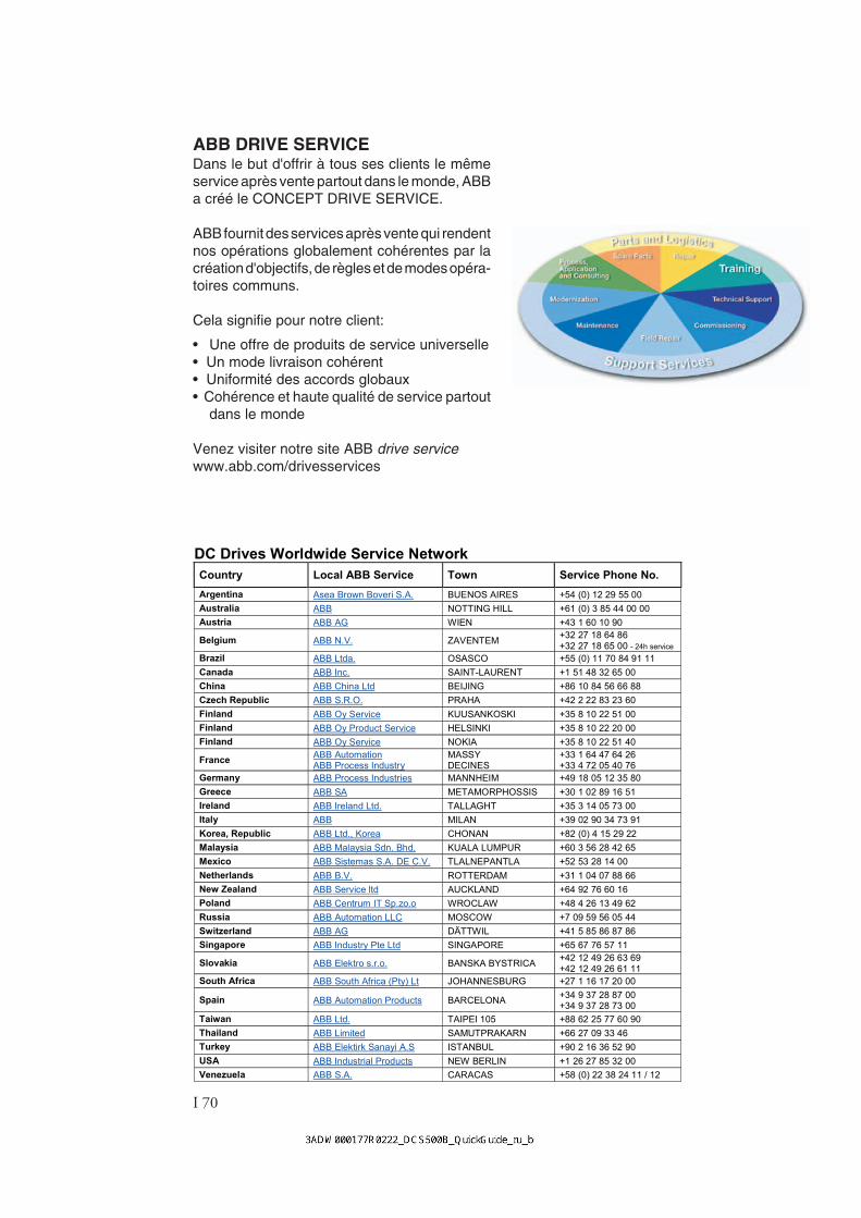
I 70
ABB DRIVE SERVICEDans le but d'offrir à tous ses clients le mêmeservice après vente partout dans le monde, ABBa créé le CONCEPT DRIVE SERVICE.
ABB fournit des services après vente qui rendentnos opérations globalement cohérentes par lacréation d'objectifs, de règles et de modes opéra-toires communs.
Cela signifie pour notre client:
• Une offre de produits de service universelle• Un mode livraison cohérent• Uniformité des accords globaux• Cohérence et haute qualité de service partout
dans le monde
Venez visiter notre site ABB drive servicewww.abb.com/drivesservices
DC Drives Worldwide Service Network Country Local ABB Service Town Service Phone No. Argentina Asea Brown Boveri S.A. BUENOS AIRES +54 (0) 12 29 55 00 Australia ABB NOTTING HILL +61 (0) 3 85 44 00 00 Austria ABB AG WIEN +43 1 60 10 90
Belgium ABB N.V. ZAVENTEM +32 27 18 64 86 +32 27 18 65 00 - 24h service
Brazil ABB Ltda. OSASCO +55 (0) 11 70 84 91 11 Canada ABB Inc. SAINT-LAURENT +1 51 48 32 65 00 China ABB China Ltd BEIJING +86 10 84 56 66 88 Czech Republic ABB S.R.O. PRAHA +42 2 22 83 23 60 Finland ABB Oy Service KUUSANKOSKI +35 8 10 22 51 00 Finland ABB Oy Product Service HELSINKI +35 8 10 22 20 00 Finland ABB Oy Service NOKIA +35 8 10 22 51 40
France ABB Automation ABB Process Industry
MASSY DECINES
+33 1 64 47 64 26 +33 4 72 05 40 76
Germany ABB Process Industries MANNHEIM +49 18 05 12 35 80 Greece ABB SA METAMORPHOSSIS +30 1 02 89 16 51 Ireland ABB Ireland Ltd. TALLAGHT +35 3 14 05 73 00 Italy ABB MILAN +39 02 90 34 73 91 Korea, Republic ABB Ltd., Korea CHONAN +82 (0) 4 15 29 22 Malaysia ABB Malaysia Sdn. Bhd. KUALA LUMPUR +60 3 56 28 42 65 Mexico ABB Sistemas S.A. DE C.V. TLALNEPANTLA +52 53 28 14 00 Netherlands ABB B.V. ROTTERDAM +31 1 04 07 88 66 New Zealand ABB Service ltd AUCKLAND +64 92 76 60 16 Poland ABB Centrum IT Sp.zo.o WROCLAW +48 4 26 13 49 62 Russia ABB Automation LLC MOSCOW +7 09 59 56 05 44 Switzerland ABB AG DÄTTWIL +41 5 85 86 87 86 Singapore ABB Industry Pte Ltd SINGAPORE +65 67 76 57 11
Slovakia ABB Elektro s.r.o. BANSKA BYSTRICA +42 12 49 26 63 69 +42 12 49 26 61 11
South Africa ABB South Africa (Pty) Lt JOHANNESBURG +27 1 16 17 20 00
Spain ABB Automation Products BARCELONA +34 9 37 28 87 00 +34 9 37 28 73 00
Taiwan ABB Ltd. TAIPEI 105 +88 62 25 77 60 90 Thailand ABB Limited SAMUTPRAKARN +66 27 09 33 46 Turkey ABB Elektirk Sanayi A.S ISTANBUL +90 2 16 36 52 90 USA ABB Industrial Products NEW BERLIN +1 26 27 85 32 00 Venezuela ABB S.A. CARACAS +58 (0) 22 38 24 11 / 12
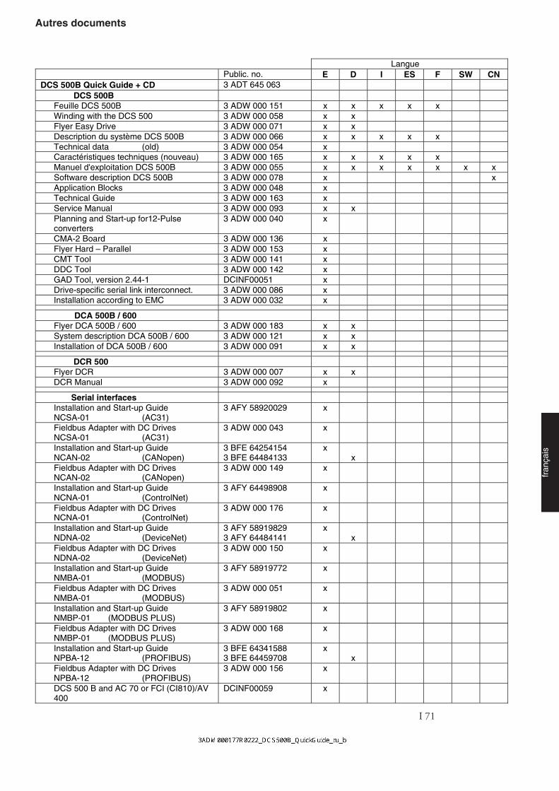
I 71
fran
çais
Autres documents
Langue Public. no. E D I ES F SW CN DCS 500B Quick Guide + CD 3 ADT 645 063 DCS 500B
Feuille DCS 500B 3 ADW 000 151 x x x x x Winding with the DCS 500 3 ADW 000 058 x x Flyer Easy Drive 3 ADW 000 071 x x Description du système DCS 500B 3 ADW 000 066 x x x x x Technical data (old) 3 ADW 000 054 x Caractéristiques techniques (nouveau) 3 ADW 000 165 x x x x x Manuel d'exploitation DCS 500B 3 ADW 000 055 x x x x x x x Software description DCS 500B 3 ADW 000 078 x x Application Blocks 3 ADW 000 048 x Technical Guide 3 ADW 000 163 x Service Manual 3 ADW 000 093 x x Planning and Start-up for12-Pulse converters
3 ADW 000 040 x
CMA-2 Board 3 ADW 000 136 x Flyer Hard – Parallel 3 ADW 000 153 x CMT Tool 3 ADW 000 141 x DDC Tool 3 ADW 000 142 x GAD Tool, version 2.44-1 DCINF00051 x Drive-specific serial link interconnect. 3 ADW 000 086 x Installation according to EMC 3 ADW 000 032 x
DCA 500B / 600 Flyer DCA 500B / 600 3 ADW 000 183 x x System description DCA 500B / 600 3 ADW 000 121 x x Installation of DCA 500B / 600 3 ADW 000 091 x x
DCR 500 Flyer DCR 3 ADW 000 007 x x DCR Manual 3 ADW 000 092 x
Serial interfaces Installation and Start-up Guide NCSA-01 (AC31)
3 AFY 58920029 x
Fieldbus Adapter with DC Drives NCSA-01 (AC31)
3 ADW 000 043 x
Installation and Start-up Guide NCAN-02 (CANopen)
3 BFE 64254154 3 BFE 64484133
x x
Fieldbus Adapter with DC Drives NCAN-02 (CANopen)
3 ADW 000 149 x
Installation and Start-up Guide NCNA-01 (ControlNet)
3 AFY 64498908 x
Fieldbus Adapter with DC Drives NCNA-01 (ControlNet)
3 ADW 000 176 x
Installation and Start-up Guide NDNA-02 (DeviceNet)
3 AFY 58919829 3 AFY 64484141
x x
Fieldbus Adapter with DC Drives NDNA-02 (DeviceNet)
3 ADW 000 150 x
Installation and Start-up Guide NMBA-01 (MODBUS)
3 AFY 58919772 x
Fieldbus Adapter with DC Drives NMBA-01 (MODBUS)
3 ADW 000 051 x
Installation and Start-up Guide NMBP-01 (MODBUS PLUS)
3 AFY 58919802 x
Fieldbus Adapter with DC Drives NMBP-01 (MODBUS PLUS)
3 ADW 000 168 x
Installation and Start-up Guide NPBA-12 (PROFIBUS)
3 BFE 64341588 3 BFE 64459708
x x
Fieldbus Adapter with DC Drives NPBA-12 (PROFIBUS)
3 ADW 000 156 x
DCS 500 B and AC 70 or FCI (CI810)/AV 400
DCINF00059 x
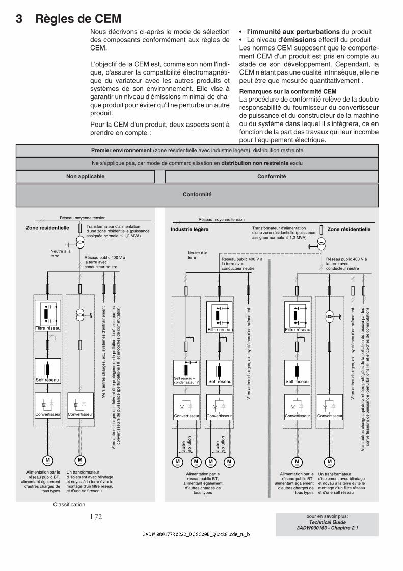
I 72 pour en savoir plus:Technical Guide
3ADW000163 - Chapitre 2.1
3 Règles de CEM
Classification
Non applicable
Premier environnement (zone résidentielle avec industrie légère), distribution restreinte
Ne s'applique pas, car mode de commercialisation en distribution non restreinte exclu
Conformité
Conformité
Nous décrivons ci-après le mode de sélectiondes composants conformément aux règles deCEM.
L'objectif de la CEM est, comme son nom l'indi-que, d'assurer la compatibilité électromagnéti-que du variateur avec les autres produits etsystèmes de son environnement. Elle vise àgarantir un niveau d'émissions minimal de cha-que produit pour éviter qu'il ne perturbe un autreproduit.
Pour la CEM d'un produit, deux aspects sont àprendre en compte :
• l'immunité aux perturbations du produit• Le niveau d'émissions effectif du produitLes normes CEM supposent que le comporte-ment CEM d'un produit est pris en compte austade de son développement. Cependant, laCEM n'étant pas une qualité intrinsèque, elle nepeut être que mesurée quantitativement .
Remarques sur la conformité CEMLa procédure de conformité relève de la doubleresponsabilité du fournisseur du convertisseurde puissance et du constructeur de la machineou du système dans lequel il s'intégrera, ce enfonction de la part des travaux qui leur incombepour l'équipement électrique.
MM
Filtre réseau
Convertisseur
Self réseau
Transformateur d'alimentation d'une zone résidentielle (puissance assignée normale ≤ 1,2 MVA)
Réseau public 400 V à la terre avec conducteur neutre
Réseau moyenne tension
Neutre à la terre
Ve
rs a
utr
es c
harg
es,
ex.
, sy
stèm
es
d'e
ntra
înem
ent
Un transformateur d'isolement avec blindage et noyau à la terre évite le montage d'un filtre réseau et d'une self réseau
Alimentation par le réseau public BT,
alimentant également d'autres charges de
tous types
Zone résidentielle
Ve
rs a
utr
es c
harg
es
qui d
oive
nt ê
tre
prot
égée
s d
e la
po
llutio
n du
ré
seau
pa
r le
s co
nve
rtis
seu
rs d
e p
uis
sanc
e (p
ert
urba
tions
HF
et e
nco
ches
de
com
mut
atio
n)
Convertisseur
MMMM MM
autr
e so
lutio
n
Self réseau + condensateur Y
Alimentation par le réseau public BT,
alimentant également d'autres charges de
tous types
Industrie légère
autr
e so
lutio
nRéseau moyenne tension
Transformateur d'alimentation d'une zone résidentielle (puissance assignée normale ≤ 1,2 MVA)
Neutre à la terre Réseau public 400 V à
la terre avec conducteur neutre
Ve
rs a
utr
es c
harg
es,
ex.
, sy
stèm
es
d'e
ntra
înem
ent
Filtre réseau
Self réseau
Convertisseur Convertisseur
Alimentation par le réseau public BT,
alimentant également d'autres charges de
tous types
Un transformateur d'isolement avec blindage et noyau à la terre évite le montage d'un filtre réseau et d'une self réseau
Ve
rs a
utr
es c
harg
es,
ex.
, sy
stèm
es
d'e
ntra
înem
ent
Ve
rs a
utr
es c
harg
es
qui d
oive
nt ê
tre
prot
égée
s d
e la
po
llutio
n du
ré
seau
pa
r le
s co
nve
rtis
seu
rs d
e p
uis
sanc
e (p
ert
urba
tions
HF
et e
nco
ches
de
com
mut
atio
n)
Filtre réseau
Self réseau
Convertisseur Convertisseur
Réseau public 400 V à la terre avec conducteur neutre
Zone résidentielle
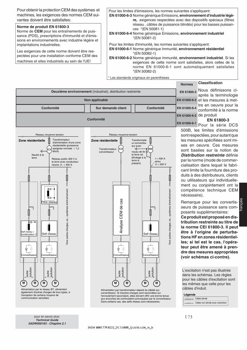
I 73
fran
çais
pour en savoir plus:Technical Guide
3ADW000163 - Chapitre 2.1
Classification
Nous définissons ci-après la terminologieet les mesures à met-tre en oeuvre pour laconformité à la normede produit
EN 61800-3Pour la série DCS
Pour obtenir la protection CEM des systèmes etmachines, les exigences des normes CEM sui-vantes doivent être satisfaites:
Norme de produit EN 61800-3Norme de CEM pour les entraînements de puis-sance (PDS), prescriptions d'immunité et d'émis-sions en environnements avec industrie légère etimplantations industrielles.
Les exigences de cette norme doivent être res-pectées pour une installation conforme CEM des
machines et sites industriels au sein de l'UE!
L'excitation n'est pas illustréedans les schémas. Les règlespour les câbles d'excitation sontles mêmes que celle pour lescâbles d'induit.
500B, les limites d'émissionssont respectées, pour autant queles mesures spécifiées sont mi-ses en oeuvre. Ces mesuressont basées sur la notion deDistribution restreinte définiepar la norme (mode de commer-cialisation dans lequel le fabri-cant limite la fourniture des pro-duits à des distributeurs, clientsou utilisateurs qui individuelle-ment ou conjointement ont lacompétence technique CEMnécessaire).
Remarque pour les convertis-seurs de puissance sans com-posants supplémentaires:Ce produit est proposé en dis-tribution restreinte au titre dela norme CEI 61800-3. Il peutêtre à l'origine de perturba-tions HF en zones résidentiel-les; si tel est le cas, l'opéra-teur peut être amené à pren-dre des mesures appropriées(voir schémas ci-contre).
MMMM
Réseau public 400 V à la terre avec conducteur neutre; 3~ ≤ 400 A
Alimentation par le réseau BT, alimentant également d'autres charges de tous types, à l'exception de certains moyens de communication sensibles
Zone résidentielle
Réseau moyenne tension
Transformateur d'alimentation d'une zone résidentielle (puissance assignée normale ≤ 1,2 MVA)
Neutre à la terre
Ve
rs a
utr
es c
harg
es,
ex.
, sy
stèm
es
d'e
ntra
înem
ent
autr
e so
lutio
n
autr
e so
lutio
n
Convertisseur Convertisseur
Self réseau
Filtre réseau
Self réseau + condensateur Y
MMMM
Transformateur-convertisseur
Ana
lyse
CE
M d
e ca
s
Transformate-ur-convertiss-eur avec
noyau de fer à la terre (et blindage à la terre si présent)
I > 400 A et/ou U > 500 V
Alimentation par transformateur séparé du (dédié au) convertisseur. Si d'autres charges sont raccordées sur l'enroulement secondaire, elles doivent offrir une bonne tenue aux encoches de commutation provoquées par le convertisseur. Dans certains cas, des selfs réseau sont nécessaires.
Zone résidentielle
Réseau moyenne tension
Convertisseur Convertisseur
autr
e so
lutio
n
autr
e so
lutio
n
Ver
s au
tres
cha
rges
, ex.
, sy
stèm
es
d'e
ntra
înem
ent
Self réseau
Légende
Câble non blindé avec restriction
Câble blindé
Pour les limites d'émissions, les normes suivantes s'appliquent:EN 61000-6-3 Norme générique Emissions, environnement d'industrie légè-
re, exigences respectées avec des dispositifs spéciaux (filtresréseau , câbles de puissance blindés) pour les basses puissan-ces *(EN 50081-1)
EN 61000-6-4 Norme générique Emissions, environnement industriel*(EN 50081-2)
Pour les limites d'immunité, les normes suivantes s'appliquent:EN 61000-6-1 Norme générique Immunité, environnement résidentiel
*(EN 50082-1)EN 61000-6-2 Norme générique Immunité, environnement industriel. Si les
exigences de cette norme sont satisfaites, alors celles de lanorme EN 61000-6-1 sont automatiquement satisfaites*(EN 50082-2)
* Les standards originaux en parenthèses
EN 61800-3
EN 61000-6-3
EN 61000-6-4
EN 61000-6-2
EN 61000-6-1
Conformité
Conformité
Deuxième environnement (industriel), distribution restreinte
Sur demande client Conformité
Non applicable
Normes
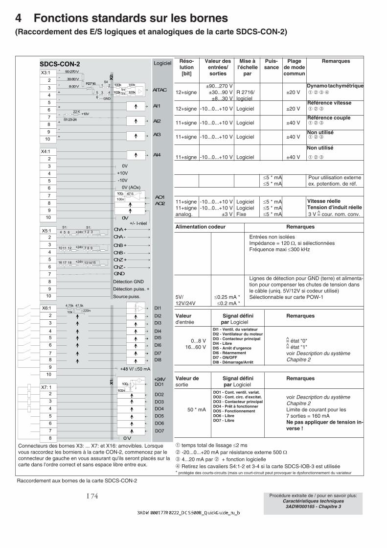
I 74 Procédure extraite de / pour en savoir plus:Caractéristiques techniques
3ADW000165 - Chapitre 3
4 Fonctions standards sur les bornes(Raccordement des E/S logiques et analogiques de la carte SDCS-CON-2)
Raccordement aux bornes de la carte SDCS-CON-2
Connecteurs des bornes X3: ... X7: et X16: amovibles. Lorsquevous raccordez les borniers à la carte CON-2, commencez par leconnecteur de gauche en vous assurant qu'ils seront placés sur lacarte dans l'ordre correct et sans espace libre entre eux.
X2:
X1:
AITAC
90-270 V
30-90 V
8-30 V
+24V
AI4
ChA +ChA -
ChB +ChB -ChZ +ChZ -GND
0 V
R2716
+10V
S1:23-24
100µ
≤
1n1n
100n
100k
100k 100k
Power-Source
Sense GNDSense Power +
0V
AI2
AI3
AI1-
+
-
+
-
+
-
-
-
+
AO1AO2
+/- I-act
47.5100µ
100n
0V (AOx)
+10V0V
-10V
DI1
DI2DI3
DI4DI5DI6
DI7DI8
47.5k220n10k
4.75k
DO4DO5
DO7
DO1
DO2DO3
DO6
22 K
345
87
6
7
9
X6:1 2 3
4 5 6
7 8
10
4 5
7
1 2 3
6
4
23
65
910
89
10
2
45
7
23
6
89
10
8
X3:1
X4:1
X5:1
X7:
SDCS-CON-2 Software
+24V 7 8 910 11 12
+24V 13141516 17 18
+24V4 5 6S1:
1 2 3S1:
GND
1 2
3 456
S4
Source puiss.
Détection GNDDétection puiss. +
+/- I-réel
Logiciel Réso- Valeur des Mise à Puis- Plage Remarqueslution entrées/ l'échelle sance de mode[bit] sorties par commun
±90...270 V12+signe ±30...90 V R 2716/ ±20 V ➀ ➁ ➂ ➃
±8...30 V logiciel
12+signe -10...0...+10 V Logiciel ±20 V ➀ ➁ ➂
11+signe -10...0...+10 V Logiciel ±40 V ➀ ➁ ➂
11+signe -10...0...+10 V Logiciel ±40 V ➀ ➁ ➂
11+signe -10...0...+10 V Logiciel ±40 V ➀ ➁ ➂
≤5 * mA Pour utilisation externe≤5 * mA ex. potentiom. de réf.
11+signe -10...0...+10 V Logiciel ≤5 * mA11+signe -10...0...+10 V Logiciel ≤5 * mAanalog. ±3 V Fixe ≤5 * mA 3 V = cour. nom. conv.
Alimentation codeur Remarques
Entrées non isoléesImpédance = 120 Ω, si sélectionnéesFréquence maxi ≤300 kHz
Lignes de détection pour GND (terre) et alimenta-tion pour compenser les chutes de tension dansle câble (uniq. 5V/12V si codeur utilisé)
5V/ ≤0.25 mA * Sélectionnable sur carte POW-112V/24V ≤0.2 mA *
Valeur Signal défini Remarquesd'entrée par Logiciel
0...8 V = état "0"16...60 V = état "1"
voir Description du systèmeChapitre 2
Valeur de Signal défini Remarquessortie par Logiciel
voir Description du systèmeChapitre 2
50 * mA Limite de courant pour les7 sorties = 160 mANe pas appliquer de tension in-verse !
➀ temps total de lissage ≤2 ms➁ -20...0...+20 mA par résistance externe 500 Ω➂ 4...20 mA par ➁ + fonction logicielle➃ Retirez les cavaliers S4:1-2 et 3-4 si la carte SDCS-IOB-3 est utilisée* protégée des courts-circuits (mais un court-circuit peut provoquer le dysfonctionnement du variateur
Référence vitesse
Dynamo tachymétrique
Référence couple
Non utilisé
Non utilisé
Vitesse réelleTension d'induit réelle
DI1 - Ventil. du variateurDI2 - Ventilateur du moteurDI3 - Contacteur principalDI4 - LibreDI5 - Arrêt d'urgenceDI6 - RéarmementDI7 - ON/OFFDI8 - Démarrage/Arrêt
DO1 - Cont. ventil. variat.DO2 - Cont. circ. d'excitat.DO3 - Contacteur principalDO4 - Prêt à fonctionnerDO5 - FonctionnementDO6 - LibreDO7 - Libre
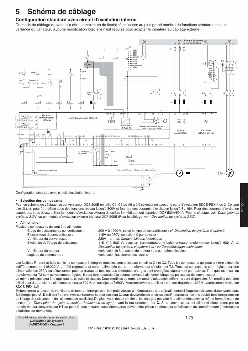
I 75
fran
çais
5 Schéma de câblage
Procédure extraite de / pour en savoir plus:Description du système
3ADW000066 - Chapitre 3
Configuration standard avec circuit d'excitation interne
Configuration standard avec circuit d'excitation interneCe mode de câblage du variateur offre le maximum de flexibilité et l'accès au plus grand nombre de fonctions standards de sur-veillance du variateur. Aucune modification logicielle n'est requise pour adapter le variateur au câblage externe.
• Selection des composantsPour ce schéma de câblage, un convertisseur DCS 500B en taille C1, C2 ou A5 a été sélectionné avec une carte d'excitation SDCS-FEX-1 ou 2. Ce typed'excitation peut être utilisé sous des tensions réseau jusqu'à 500V et fournira des courants d'excitation jusqu'à 6 / 16A. Pour des courants d'excitationsupérieurs, vous devez utiliser le module d'excitation externe de calibre immédiatement supérieur DCF 503A/504A (Pour le câblage, voir Description dusystème 3.3/1) ou un module d'excitation externe triphasé DCF 500B (Pour le câblage, voir Description du système 3.5/2).
• AlimentationPlusieurs composants doivent être alimentés:
- Etage de puissance du convertisseur : 200 V à 1000 V, selon le type de convertisseur ; cf. Description du système chapitre 2- Electronique du convertisseur : 115V ou 230V, sélectionné par cavalier- Ventilateur du convertisseur: 230V 1 ph.; cf. Caractéristiques techniques- Excitation de l'étage de puissance: 115 V à 500 V; avec un transformateur d'isolement/autotransformateur jusqu'à 600 V; cf.
Description du système chapitere 2 et / ou Caractéristiques techniques- Ventilateur du moteur: varie selon la fabrication du moteur / les contraintes locales- Logique de commande : varie selon les contraintes locales
Les fusibles F1 sont utilisés car ils ne sont pas pré-intégrés dans les convertisseurs en tailles C1 et C2. Tous les composants qui peuvent être alimentésindifféremment en 115/230 V, ont été regroupés et seront alimentés par un transformateur d'isolement T2. Tous les composants sont réglés pour unealimentation en 230 V ou sélectionnés pour ce niveau de tension. Les différentes charges sont protégées séparément par fusibles. Tant que les prises dutransformateur T2 sont correctement réglées, il peut être raccordé à la source servant à alimenter l'étage de puissance du convertisseur.Le même principe peut être appliqué au circuit d'excitation. Deux modèles de transformateur d'adaptation différents sont disponibles. Un modèle peut êtreutilisé pour des tensions d'alimentation jusqu'à 500 V, et l'autre jusqu'à 690 V. Vous ne devez pas utiliser les prises du primaire 690 V avec la carte d'excitationSDCS-FEX-1/2!En fonction de la tension du ventilateur du moteur, l'énergie peut être prélevée sur la même source que celle alimentant l'étage de puissance du convertisseur.Si l'énergie pour A, D et E doit être prélevée sur la même source que pour C, vous devez décider si les fusibles F1 auront ou non une double fonction (protectionde l'étage de puissance + de l'alimentation auxiliaire).De plus, vous devez vérifier si les charges peuvent être alimentées avec la même forme d'onde detension (cf. Description du système chapitre Inductance de ligne) avant le raccordement sur C. Si le convertisseur est alimenté directement par untransformateur-convertisseur HT au point C, des mesures supplémentaires doivent être prises en phase de spécification de l'entraînement (informationsdétaillées sur demande).
IN3
OUT3
IN1
OUT1
V5
V6
V1
V2
X96:
DO8
1 2 X99: 1 2 X2: 4 5 X2: 1 2 3 U1 W1V1 PE
K1 F6
K20
K21K20 K3 K1
X96:1
X96:2
L1 L2 L3
F1
F3
K31 3
2 4
M~
T3F23
4
1
2
T2690V660V600V575V525V500V450V415V400V380V
115V
230V
K15
K15
S1
1
2
K6 K8
X2:4
X2:5
K11K10
K21
500V460V415V400V
365V350V265V250V90V60V30V
X33
C 1 D 1
AITAC AI1 AI2 AI3 AI4+10V -10V AO1 AO2 IACT DI1 DI2 DI3 DI4 DI5 DI6 DI7 DI8 +48V DO1 DO2 DO3 DO4 DO5 DO6 DO7_ _ _ _ _+ + + + +
T
T M
0V0V0V0V0V
X3: 1 2 3 4 5 6 7 8 9 10 X4: 1 2 3 4 5 6 7 8 9 10 X6: 1 2 3 4 5 6 7 8 9 10 X7: 1 2 3 4 5 6 7 8 1...10X5:+ _
+
_
K1
K20
K21
K6
K8
1
2S1
K11
K10
S4
5 6
2 4 6
1 3 5K6
F51
2F8
1
2F7
1
2
2
1
4
3
6
5F6
I > I > I >
13
14
UV
WM3~
K11 3 5
2 4 6
L1
1
2
3
4K8
13
14
X1: 1 7
L3
X1: 5 3+ _
L1 N L1 N L1 L2 L3A C D E
Carte decommunication
(COM-x)Carte de commande (CON-2)
Alimentation(POW-1)
Moduleconvertisseur
ON
OFF ARRET
Demarrage
ARRETURG.
Excitation(SDCS-FEX-1/2)
Selon le type d'appareil, une autreconfiguration est possible
Polaritées illustrées pour fonctionnement en moteurSi borniers intermédiaires
ex., Pressostat sur module C4
Niveaux de tension voir description
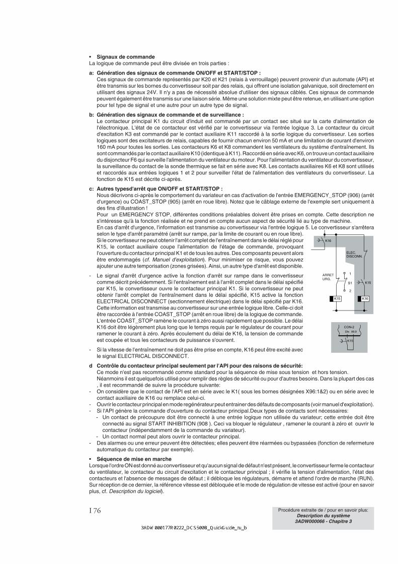
I 76 Procédure extraite de / pour en savoir plus:Description du système
3ADW000066 - Chapitre 3
• Signaux de commandeLa logique de commande peut être divisée en trois parties :
a: Génération des signaux de commande ON/OFF et START/STOP :Ces signaux de commande représentés par K20 et K21 (relais à verrouillage) peuvent provenir d'un automate (API) etêtre transmis sur les bornes du convertisseur soit par des relais, qui offrent une isolation galvanique, soit directement enutilisant des signaux 24V. Il n'y a pas de nécessité absolue d'utiliser des signaux câblés. Ces signaux de commandepeuvent également être transmis sur une liaison série. Même une solution mixte peut être retenue, en utilisant une optionpour tel type de signal et une autre pour un autre type de signal.
b: Génération des signaux de commande et de surveillance :Le contacteur principal K1 du circuit d'induit est commandé par un contact sec situé sur la carte d'alimentation del'électronique. L'état de ce contacteur est vérifié par le convertisseur via l'entrée logique 3. Le contacteur du circuitd'excitation K3 est commandé par le contact auxiliaire K11 raccordé à la sortie logique du convertisseur. Les sortieslogiques sont des excitateurs de relais, capables de fournir chacun environ 50 mA et une limitation de courant d'environ160 mA pour toutes les sorties. Les contacteurs K6 et K8 commandent les ventilateurs du système d'entraînement. Ilssont commandés par le contact auxiliaire K10 (identique à K11). Raccordé en série avec K6, on trouve un contact auxiliairedu disjoncteur F6 qui surveille l'alimentation du ventilateur du moteur. Pour l'alimentation du ventilateur du convertisseur,la surveillance du contact de la sonde thermique se fait en série avec K8. Les contacts auxiliaires K6 et K8 sont utiliséset raccordés aux entrées logiques 1 et 2 pour surveiller l'état de l'alimentation des ventilateurs du convertisseur. Lafonction de K15 est décrite ci-après.
c: Autres typesd'arrêt que ON/OFF et START/STOP :Nous décrivons ci-après le comportement du variateur en cas d'activation de l'entrée EMERGENCY_STOP (906) (arrêtd'urgence) ou COAST_STOP (905) (arrêt en roue libre). Notez que le câblage externe de l'exemple sert uniquement àdes fins d'illustration !Pour un EMERGENCY STOP, différentes conditions préalables doivent être prises en compte. Cette description nes'intéresse qu'à la fonction réalisée et ne prend en compte aucun aspect de sécurité lié au type de machine.En cas d'arrêt d'urgence, l'information est transmise au convertisseur via l'entrée logique 5. Le convertisseur s'arrêteraselon le type d'arrêt paramétré (arrêt sur rampe, par la limite de courant ou en roue libre).Si le convertisseur ne peut obtenir l'arrêt complet de l'entraînement dans le délai réglé pourK15, le contact auxiliaire coupe l'alimentation de l'étage de commande, provoquantl'ouverture du contacteur principal K1 et de tous les autres. Des composants peuvent alorsêtre endommagés (cf. Manuel d'exploitation). Pour minimiser ce risque, vous pouvezajouter une autre temporisation (zones grisées). Ainsi, un autre type d'arrêt est disponible.
- Le signal d'arrêt d'urgence active la fonction d'arrêt sur rampe dans le convertisseurcomme décrit précédemment. Si l'entraînement est à l'arrêt complet dans le délai spécifiépar K15, le convertisseur ouvre le contacteur principal K1. Si le convertisseur ne peutobtenir l'arrêt complet de l'entraînement dans le délai spécifié, K15 active la fonctionELECTRICAL DISCONNECT (sectionnement électrique) dans le délai spécifié par K16.Cette information est transmise au convertisseur sur une entrée logique libre. Celle-ci doitêtre raccordée à l'entrée COAST_STOP (arrêt en roue libre) de la logique de commande.L'entrée COAST_STOP ramène le courant à zéro aussi rapidement que possible. Le délaiK16 doit être légèrement plus long que le temps requis par le régulateur de courant pourramener le courant à zéro. Après écoulement du délai de K16, la tension de commandeest coupée et tous les contacteurs de puissance s'ouvrent.
- Si la vitesse de l'entraînement ne doit pas être prise en compte, K16 peut être excité avecle signal ELECTRICAL DISCONNECT.
d Contrôle du contacteur principal seulement par l'API pour des raisons de sécurité:Ce mode n'est pas recommandé comme standard pour la séquence de mise sous tension et hors tension.Néanmoins il est quelquefois utilisé pour remplir des règles de sécurité ou pour d'autres besoins. Dans la plupart des cas, il est recommandé de suivre la procédure suivante:
- On considère que le contact de l'API est en série avec le K1( sous les bornes désignées X96:1&2) ou en série avec lecontact auxiliaire de K16 ou remplace celui-ci.
- Ouvrir le contacteur principal en mode regénérateur peut entrainer des défauts de composants (voir manuel d'exploitation).- Si l'API génère la commande d'ouverture du contacteur principal.Deux types de contacts sont nécessaires:
- Un contact de précoupure doit être connecté à une entrée logique non utilisée du variateur; cette entrée doit êtreconnecté au signal START INHIBITION (908 ). Ceci va bloquer le régulateur , ramener le courant à zéro et ouvrir lecontacteur (indépendamment de la commande du variateur).
- Un contact normal peut alors ouvrir le contacteur principal.- Des alarmes ou une erreur peuvent être détectées; elles peuvent être réarmées ou bypassées (fonction de refermeture
automatique du contacteur par exemple).
• Séquence de mise en marcheLorsque l'ordre ON est donné au convertisseur et qu'aucun signal de défaut n'est présent, le convertisseur ferme le contacteurdu ventilateur, le contacteur du circuit d'excitation et le contacteur principal ; il vérifie la tension d'alimentation, l'état descontacteurs et l'absence de messages de défaut ; il débloque les régulateurs, démarre et attend l'ordre de marche (RUN).Sur réception de ce dernier, la référence vitesse est débloquée et le mode de régulation de vitesse est activé (pour en savoirplus, cf. Description du logiciel).
EMER.STOP
K16
K15 K16
K15
ELEC.DISCONN.
DIx
K15
X6:9CON-2
S1
1
2
ARRETURG.
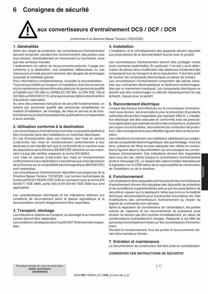
I 77
fran
çais
1. GénéralitésSelon leur degré de protection, les convertisseurs d’entraînementpeuvent comporter, pendant leur fonctionnement, des parties nuessous tension, éventuellement en mouvement ou tournantes, ainsique des surfaces chaudes.L’enlèvement non admis de recouvrements préscrits, l’usage nonconforme à la destination, une installation défectueuse ou unemanoeuvre erronée peuvent entraîner des dangers de dommagescorporels et matériels graves.Pour informations complémentaires, consulter la documentation.Tous travaux relatifs au transport, à l’installation, à la mise en serviceet à la maintenance doivent être exécutées par du personnel qualifiéet habilité (voir CEI 364 ou CENELEC HD 384, ou DIN VDE 100 etCEI 664 ou DIN/VDE 0110, ainsi que les prescriptions de préventiond’accidents nationales).Au sens des présentes instructions de sécurité fondamentales, onentend par personnel qualifié des personnes compétentes enmatière d’installation, de montage, de mise en service et de fonc-tionnement du produit et possédant les qualifications correspondantà leurs activités.
2. Utilisation conforme à la destinationLes convertisseurs d’entraînement sont des composants destinés àêtre incorporés dans des installations ou machines électriques.En cas d’incorporation dans une machine, leur mise en service(c’est-à-dire leur mise en fonctionnement conformément à leurdestination) est interdite tant que la conformité de la machine avecles dispositions de la Directive 89/392/CEE (directive sur les machi-nes) n’a pas été vérifiée; respecter la norme EN 60024.Leur mise en service (c’est-à-dire leur mise en fonctionnementconformément à leur destination) n’est admise que si les dipositionsde la Directive sur la compatibilité électromagnétique (89/336/CEE)sont respectées.Les convertisseurs d’entraînement répondent aux exigences de laDirective Basse Tension 73/23/CEE. Les normes harmonisées dela série prEN 50178/DIN VDE 0160 en connexion avec la norme EN60439-1/ VDE 0660, partie 500 et EN 60146/ VDE 0558 leur sontapplicables.
Les caractéristiques techniques et les indications relatives auxconditions de raccordement selon la plaque signalétique et ladocumentation doivent obligatoirement être respectées.
3. Transport, stockageLes indications relatives au transport, au stockage et au maniementcorrect doivent être respectées.Les conditions climatiques selon la prEN 50178 doivent être respec-tées.
4. InstallationL’installation et le refroidissement des appareils doivent répondreaux prescriptions de la documentation fournie avec le produit.
Les convertisseurs d’entraînement doivent être protégés contretoute contrainte inadmissible. En particuier, il ne doit y avoir défor-mation de pièces et/ou modification des distances d’isolement descomposants lors du transport et de la manutention. Il doit être évitéde toucher les composants électroniques et pièces de contact.Les convertisseurs d’entraînement comportent des pièces sensi-bles aux contraintes électrostatiques et facilement endommagea-bles par un maniement inadéquat. Les composants électriques nedoivent pas être endommagés ou détruits mécaniquement (le caséchéant, risques pour la santé!)
5. Raccordement électriqueLorsque des travaux sont effectués sur le convertisseur d’entraîne-ment sous tension, les prescriptions pour la prévention d’accidentsnationales doivent être respectées (par exemple VBG 4). L’installa-tion électrique doit être exécutée en conformité avec les prescrip-tions applicables (par exemple sections des conducteurs, protectionpar coupe-circuit à fusibles, raccordement du conducteur de protec-tion). Des renseignements plus détaillés figurent dans la documen-tation.Les indications concernant une installation satisfaisant aux exigen-ces de compatibilité électromagnétique, tels que blindage, mise à laterre, présence de filtres et pose adéquate des câbles et conduc-teurs) figurent dans la documentation qui accompagne les conver-tisseurs d’entraînement. Ces indications doivent être respectéesdans tous les cas, même lorsque le convertisseur d’entraînementporte le marquage CE. Le respect des valeurs limites imposées parla législation sur la CEM relève de la responsabilité du constructeurde l’installation ou de la machine.
6. FonctionnementLes installations dans lesquelles sont incorporés des convertisseursd’entraînement doivent être équipées des dispositifs de protectionet de surveillance supplémentaires prévus par les prescriptions desécurité en vigueur qui s’y appliquent, telles que la loi sur le matérieltechnique, les prescriptions pour la prévention d’accidents, etc. Desmodifications des convertisseurs d’entraînement au moyen dulogiciel de commande sont admises.Après la séparation du convertisseur de l’alimentation, les partiesactives de l’appareil et les raccordements de puissance soustension ne doivent pas être touchés immédiatement, en raison decondensateurs éventuellement chargés. Respecter à cet effet lespancartes d’avertissement fixées sur les convertisseurs d’entraîne-ment.Pendant le fonctionnement, tous les portes et recouvrements doi-vent être maintenus fermés.
7. Entretien et maintenanceLa documentation du constructeur doit être prise en considération.
CONSERVER CES INSTRUCTIONS DE SECURITE!
6 Consignes de sécurité
aux convertisseurs d'entraînement DCS / DCF / DCR
(conformes à la directive Basse Tension 73/23/CEE)
Procédure extraite de / pour en savoir plus:Safety instructions
3ADW000033
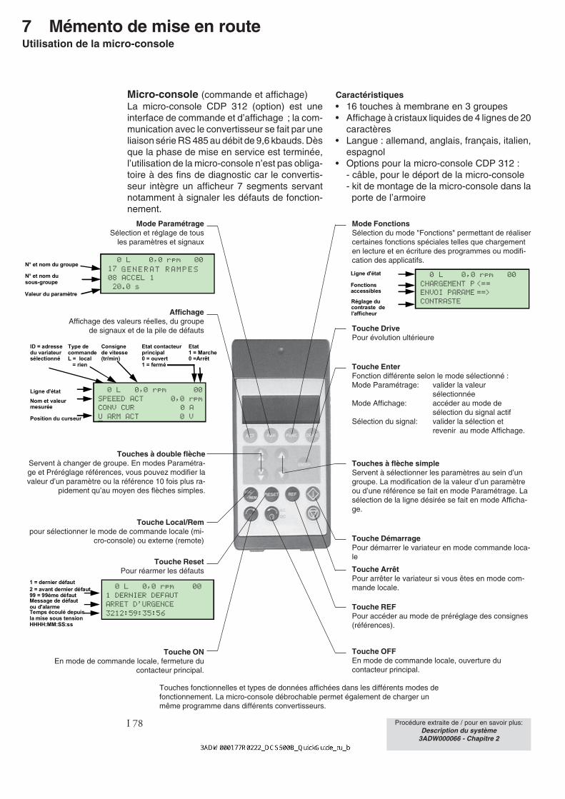
I 78
7 Mémento de mise en routeUtilisation de la micro-console
Procédure extraite de / pour en savoir plus:Description du système
3ADW000066 - Chapitre 2
Micro-console (commande et affichage)La micro-console CDP 312 (option) est uneinterface de commande et d’affichage ; la com-munication avec le convertisseur se fait par uneliaison série RS 485 au débit de 9,6 kbauds. Dèsque la phase de mise en service est terminée,l’utilisation de la micro-console n’est pas obliga-toire à des fins de diagnostic car le convertis-seur intègre un afficheur 7 segments servantnotamment à signaler les défauts de fonction-nement.
Caractéristiques• 16 touches à membrane en 3 groupes• Affichage à cristaux liquides de 4 lignes de 20
caractères• Langue : allemand, anglais, français, italien,
espagnol• Options pour la micro-console CDP 312 :
- câble, pour le déport de la micro-console- kit de montage de la micro-console dans la porte de l’armoire
Touches fonctionnelles et types de données affichées dans les différents modes defonctionnement. La micro-console débrochable permet également de charger unmême programme dans différents convertisseurs.
AffichageAffichage des valeurs réelles, du groupe
de signaux et de la pile de défauts
Mode ParamétrageSélection et réglage de tous
les paramètres et signaux
Mode FonctionsSélection du mode "Fonctions" permettant de réalisercertaines fonctions spéciales telles que chargementen lecture et en écriture des programmes ou modifi-cation des applicatifs.
Touche DrivePour évolution ultérieure
Touches à double flècheServent à changer de groupe. En modes Paramétra-ge et Préréglage références, vous pouvez modifier lavaleur d’un paramètre ou la référence 10 fois plus ra-
pidement qu’au moyen des flèches simples.
Touches à flèche simpleServent à sélectionner les paramètres au sein d’ungroupe. La modification de la valeur d’un paramètreou d’une référence se fait en mode Paramétrage. Lasélection de la ligne désirée se fait en mode Afficha-ge.
Touche EnterFonction différente selon le mode sélectionné :Mode Paramétrage: valider la valeur
sélectionnéeMode Affichage: accéder au mode de
sélection du signal actifSélection du signal: valider la sélection et
revenir au mode Affichage.
Touche Local/Rempour sélectionner le mode de commande locale (mi-
cro-console) ou externe (remote)
Touche ResetPour réarmer les défauts
Touche REFPour accéder au mode de préréglage des consignes(références).
Touche ONEn mode de commande locale, fermeture du
contacteur principal.
Touche OFFEn mode de commande locale, ouverture ducontacteur principal.
Touche DémarragePour démarrer le variateur en mode commande loca-le
Touche ArrêtPour arrêter le variateur si vous êtes en mode com-mande locale.
0 L 0,0 rpm 0017 08 ACCEL 1 20.0 s
N° et nom du groupe
N° et nom du sous-groupe
Valeur du paramètre
GENERAT RAMPES
0 L 0,0 rpm 001 DERNIER DEFAUTARRET D'URGENCE3212:59:35:56
1 = dernier défaut2 = avant dernier défaut99 = 99ème défautMessage de défautou d'alarmeTemps écoulé depuisla mise sous tensionHHHH:MM:SS:ss
0 L 0,0 rpm 00CHARGEMENT P <==ENVOI PARAME ==>CONTRASTE
Ligne d'état
Fonctions accessibles
Réglage du contraste de l'afficheur
0 L 0,0 rpm 00SPEEED ACT 0,0 rpmCONV CUR 0 AU ARM ACT 0 V
ID = adresse du variateursélectionné
Type de commandeL = local = rien
Consignede vitesse(tr/min)
Etat contacteur principal0 = ouvert1 = fermé
Etat 1 = Marche0 =Arrêt
Ligne d'étatNom et valeur mesurée
Position du curseur
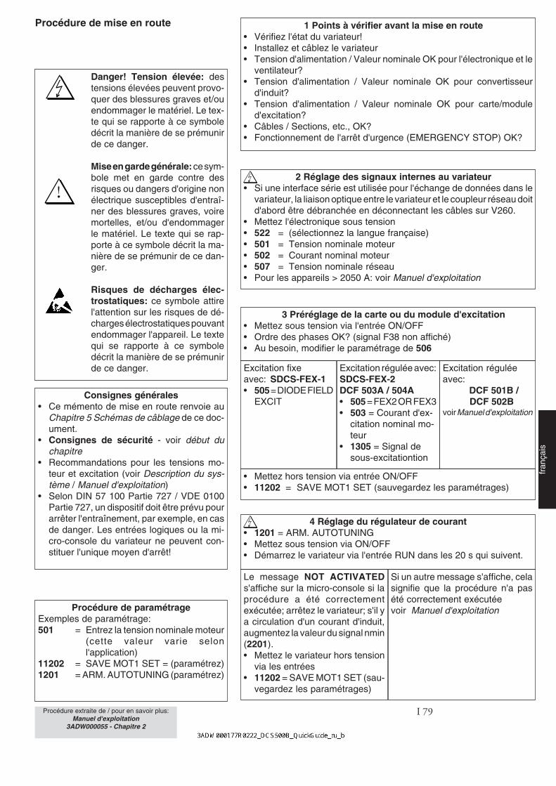
I 79
fran
çais
Procédure de mise en route
Procédure extraite de / pour en savoir plus:Manuel d'exploitation
3ADW000055 - Chapitre 2
Danger! Tension élevée: destensions élevées peuvent provo-quer des blessures graves et/ouendommager le matériel. Le tex-te qui se rapporte à ce symboledécrit la manière de se prémunirde ce danger.
Mise en garde générale: ce sym-bole met en garde contre desrisques ou dangers d'origine nonélectrique susceptibles d'entraî-ner des blessures graves, voiremortelles, et/ou d'endommagerle matériel. Le texte qui se rap-porte à ce symbole décrit la ma-nière de se prémunir de ce dan-ger.
Risques de décharges élec-trostatiques: ce symbole attirel'attention sur les risques de dé-charges électrostatiques pouvantendommager l'appareil. Le textequi se rapporte à ce symboledécrit la manière de se prémunirde ce danger.
1 Points à vérifier avant la mise en route• Vérifiez l'état du variateur!• Installez et câblez le variateur• Tension d'alimentation / Valeur nominale OK pour l'électronique et le
ventilateur?• Tension d'alimentation / Valeur nominale OK pour convertisseur
d'induit?• Tension d'alimentation / Valeur nominale OK pour carte/module
d'excitation?• Câbles / Sections, etc., OK?• Fonctionnement de l'arrêt d'urgence (EMERGENCY STOP) OK?
2 Réglage des signaux internes au variateur• Si une interface série est utilisée pour l'échange de données dans le
variateur, la liaison optique entre le variateur et le coupleur réseau doitd'abord être débranchée en déconnectant les câbles sur V260.
• Mettez l'électronique sous tension• 522 = (sélectionnez la langue française)• 501 = Tension nominale moteur• 502 = Courant nominal moteur• 507 = Tension nominale réseau• Pour les appareils > 2050 A: voir Manuel d'exploitation
3 Préréglage de la carte ou du module d'excitation• Mettez sous tension via l'entrée ON/OFF• Ordre des phases OK? (signal F38 non affiché)• Au besoin, modifier le paramétrage de 506
Excitation fixeavec: SDCS-FEX-1• 505 = DIODE FIELD
EXCIT
Excitation régulée avec:SDCS-FEX-2DCF 503A / 504A• 505 = FEX2 OR FEX3• 503 = Courant d'ex-
citation nominal mo-teur
• 1305 = Signal desous-excitationtion
Excitation réguléeavec:
DCF 501B / DCF 502B
voir Manuel d'exploitation
• Mettez hors tension via entrée ON/OFF• 11202 = SAVE MOT1 SET (sauvegardez les paramétrages)
4 Réglage du régulateur de courant• 1201 = ARM. AUTOTUNING• Mettez sous tension via ON/OFF• Démarrez le variateur via l'entrée RUN dans les 20 s qui suivent.
Le message NOT ACTIVATEDs'affiche sur la micro-console si laprocédure a été correctementexécutée; arrêtez le variateur; s'il ya circulation d'un courant d'induit,augmentez la valeur du signal nmin(2201).• Mettez le variateur hors tension
via les entrées• 11202 = SAVE MOT1 SET (sau-
vegardez les paramétrages)
Si un autre message s'affiche, celasignifie que la procédure n'a pasété correctement exécutéevoir Manuel d'exploitationProcédure de paramétrage
Exemples de paramétrage:501 = Entrez la tension nominale moteur
(cette valeur varie selonl'application)
11202 = SAVE MOT1 SET = (paramétrez)1201 = ARM. AUTOTUNING (paramétrez)
Consignes générales• Ce mémento de mise en route renvoie au
Chapitre 5 Schémas de câblage de ce doc-ument.
• Consignes de sécurité - voir début duchapitre
• Recommandations pour les tensions mo-teur et excitation (voir Description du sys-tème / Manuel d'exploitation)
• Selon DIN 57 100 Partie 727 / VDE 0100Partie 727, un dispositif doit être prévu pourarrêter l'entraînement, par exemple, en casde danger. Les entrées logiques ou la mi-cro-console du variateur ne peuvent con-stituer l'unique moyen d'arrêt!
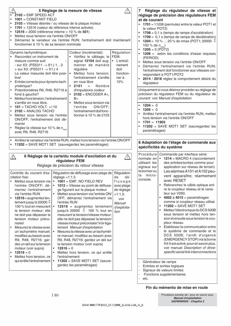
I 80 Procédure extraite de / pour en savoir plus:Manuel d'exploitation
3ADW000055 - Chapitre 2
5 Réglage de la mesure de vitesse• 2102 = EMF SPEED ACT• 1001 = CONSTANT FIELD• 2103 = Vitesse désirée / ou vitesse de la plaque moteur• 1701 = 12516 (valeur de référence interne activée)• 12516 = 2000 (référence interne = 10 % de 501)• Mettez sous tension via l'entrée ON/OFF• Démarrez le variateur via l'entrée RUN; l'entraînement doit maintenant
fonctionner à 10 % de sa tension nominale
Dynamo tachymétrique:• Raccordez un instrument de
mesure comme suit: -- sur X3: (PS5311 → X1:) 1…3+ sur X3: (PS5311 → X1:) 4La valeur mesurée doit être posi-tive!
• Entrée correcte pour dynamo tach-ymétrique?
• Potentiomètres R9, R48, R2716 àfond à gauche?
• Mettez hors tension; l'entraînements'arrête en roue libre.
• 101 = TACHO VOLT. +/-10• 2102 = ANALOG TACHO• Mettez sous tension via l'entrée
ON/OFF; l'entraînement doit dé-marrer
• Réglez la vitesse sur 10 % de nmax
avec R9, R48, R2716
Codeur (incrémental):• Vérifiez le câblage; le
signal 12104 doit aug-menter de manièrerégulière
• Mettez hors tension;l'entraînement s'arrêteen roue libre
• 2101 = Nombred'impulsions codeur
• 2102 = ENCODER A+,B+
• Mettez sous tension vial'entrée ON/OFF;l'entraînement doit fonc-tionner à 10 % de 2103
RégulationFEM:• L'entraî-
nementdoitfonction-ner à10%
• Arrêtez le variateur via l'entrée RUN, mettez hors tension via l'entrée ON/OFF• 11202 = SAVE MOT1 SET (sauvegardez les paramétrages)
7 Réglage du régulateur de vitesse etréglage de précision des régulateurs FEMet de courant• 1701 = 11206 (permutez entre la valeur POT1 et
la valeur POT2)• 1708 = 0,1 s (temps de rampe d'accélération)• 1709 = 0,1 s (temps de rampe de décélération)• 1204 = 10 % … 20 % de nmax (POT1; 20000 =
100 % de nmax)• 1205 = 0 (POT2)• 1206 = selon les conditions d'essai requises
(PERIOD)• Mettez sous tension via l'entrée ON/OFF• Démarrez l'entraînement via l'entrée RUN;
l'entraînement doit fonctionner aux vitesses cor-respondant à POT1/POT2
• 2014 / 2018 réglez le comportement désiré durégulateur
Uniquement si vous désirez procéder au réglage deprécision du régulateur FEM ou du régulateur decourant: voir Manuel d'exploitation
• 1204 = 0• 1205 = 0• Arrêtez l'entraînement via l'entrée RUN, mettez
hors tension via l'entrée ON/OFF• 1701 = 11903• 11202 = SAVE MOT1 SET (sauvegardez les
paramétrages)
8 Adaptation de l'étage de commande auxspécificités du système
6 Réglage de la carte/du module d'excitation et durégulateur FEM
Réglage de précision du retour vitesse
Contrôle du courant d'ex-citation fixe:• Mettez sous tension via
l'entrée ON/OFF; dé-marrez l'entraînementvia l'entrée RUN
• 12516 = augmentez len-tement jusqu'à 20000 =100 % tout en mesurantla tension moteur; ellene doit pas dépasser latension moteur préco-nisée!
• Mesurez la vitesse avecun tachymètre manuel;modifiez au besoin avecR9, R48, R2716; gar-dez un œil sur la tensionmoteur (voir supra)
• 12516 = 0• Mettez hors tension, ce
qui arrête l'entraînement
Régulation de défluxage avec plage deréglage <1:1,5• 1001 = EMF, NO FIELD REV• 1012 = Vitesse au point de défluxa-
ge figurant sur la plaque moteur• Mettez sous tension via l'entrée ON/
OFF; démarrez l'entraînement vial'entrée RUN
• 12516 = augmentez lentementjusqu'à 20000 = 100 % tout enmesurant la tension/vitesse moteur;elle ne doit pas dépasser la tension/vitesse moteur préconisée! Voir éga-lement Manuel d'exploitation
• Mesurez la vitesse avec un tachymèt-re manuel; modifiez au besoin avecR9, R48, R2716; gardez un œil surla tension moteur (voir supra)
• 12516 = 0• Mettez hors tension, ce qui arrête
l'entraînement• 11202 = SAVE MOT1 SET (sauve-
gardez les paramétrages)
Régulationde dé-f l u x a g eavec plagede réglage>1:1,5:
voirManueld'exploita-tion
Procédurenormale : enutilisant lessignaux surle bornier oula micro-console.
Commande par interface série:• 1214 = MACRO 4 (raccordement
des entrées/sorties comme pourapplication sur réseau de terrain)Les alarmes A101 et A102 peu-vent apparaître; réarmementavec RESET
• Rebranchez le câble optique ent-re le coupleur réseau et le varia-teur sur V260.
• 4002 à 4015 = paramétragescomme si coupleur réseau utilisé
• 11202 = SAVE MOT1 SET• Mettez l'électronique du DCS 500B
sous tension et mettez hors ten-sion et ensuite sous tension le cou-pleur réseau
• Etablissez la communication entrele système de commande et leDCS 500B; l'arrêt d'urgence(EMERGENCY STOP) via la borneX4:5 est activé; pour en savoir plus,voir manuel Description of drive-specific serial link interconnections
- Générateur de rampe- Entrées et sorties logiques- Signaux de valeurs limites- Fonctions supplémentaires- etc.
Fin du mémento de mise en route
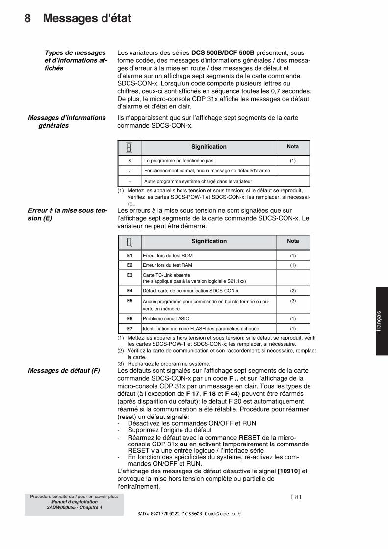
I 81
fran
çais
8 Messages d'état
Types de messages et d’informations af-fichés
Les variateurs des séries DCS 500B/DCF 500B présentent, sous forme codée, des messages d’informations générales / des messa-ges d’erreur à la mise en route / des messages de défaut et d’alarme sur un affichage sept segments de la carte commande SDCS-CON-x. Lorsqu’un code comporte plusieurs lettres ou chiffres, ceux-ci sont affichés en séquence toutes les 0,7 secondes. De plus, la micro-console CDP 31x affiche les messages de défaut, d’alarme et d’état en clair.
Messages d’informations générales
Ils n’apparaissent que sur l’affichage sept segments de la carte commande SDCS-CON-x.
Signification Nota
8 Le programme ne fonctionne pas (1)
. Fonctionnement normal, aucun message de défaut/d’alarme
L Autre programme système chargé dans le variateur
(1) Mettez les appareils hors tension et sous tension; si le défaut se reproduit, vérifiez les cartes SDCS-POW-1 et SDCS-CON-x; les remplacer, si nécessai-re..
Erreur à la mise sous ten-sion (E)
Les erreurs à la mise sous tension ne sont signalées que sur l’affichage sept segments de la carte commande SDCS-CON-x. Le variateur ne peut être démarré.
Signification Nota
E1 Erreur lors du test ROM (1)
E2 Erreur lors du test RAM (1)
E3 Carte TC-Link absente (ne s’applique pas à la version logicielle S21.1xx)
E4 Défaut carte de communication SDCS-CON-x (2)
E5 Aucun programme pour commande en boucle fermée ou ou-
verte en mémoire
(3)
E6 Problème circuit ASIC (1)
E7 Identification mémoire FLASH des paramètres échouée (1)
(1) Mettez les appareils hors tension et sous tension; si le défaut se reproduit, vérifieles cartes SDCS-POW-1 et SDCS-CON-x; les remplacer, si nécessaire.
(2) Vérifiez la carte de communication et son raccordement; si nécessaire, remplacela carte.
(3) Rechargez le programme système. Messages de défaut (F)
Les défauts sont signalés sur l’affichage sept segments de la carte commande SDCS-CON-x par un code F .. et sur l’affichage de la micro-console CDP 31x par un message en clair. Tous les types de défaut (à l’exception de F 17, F 18 et F 44) peuvent être réarmés (après disparition du défaut); le défaut F 20 est automatiquement réarmé si la communication a été rétablie. Procédure pour réarmer (reset) un défaut signalé: - Désactivez les commandes ON/OFF et RUN - Supprimez l’origine du défaut - Réarmez le défaut avec la commande RESET de la micro-
console CDP 31x ou en activant temporairement la commande RESET via une entrée logique / l’interface série
- En fonction des spécificités du système, ré-activez les com-mandes ON/OFF et RUN.
L’affichage des messages de défaut désactive le signal [10910] et provoque la mise hors tension complète ou partielle de l’entraînement.
Procédure extraite de / pour en savoir plus:Manuel d'exploitation
3ADW000055 - Chapitre 4
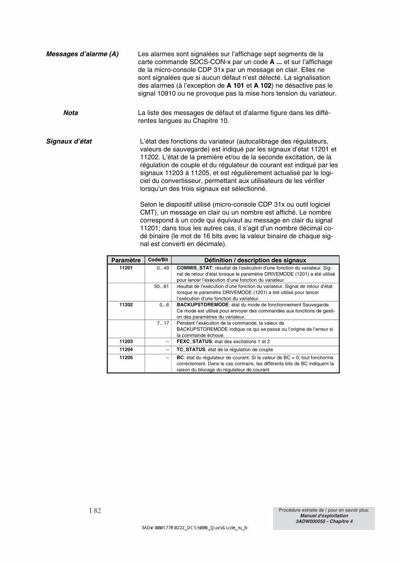
I 82
Messages d’alarme (A)
Les alarmes sont signalées sur l’affichage sept segments de la carte commande SDCS-CON-x par un code A ... et sur l’affichage de la micro-console CDP 31x par un message en clair. Elles ne sont signalées que si aucun défaut n’est détecté. La signalisation des alarmes (à l’exception de A 101 et A 102) ne désactive pas le signal 10910 ou ne provoque pas la mise hors tension du variateur.
Nota La liste des messages de défaut et d’alarme figure dans les diffé-rentes langues au Chapitre 10.
Signaux d’état
L’état des fonctions du variateur (autocalibrage des régulateurs, valeurs de sauvegarde) est indiqué par les signaux d’état 11201 et 11202. L’état de la première et/ou de la seconde excitation, de la régulation de couple et du régulateur de courant est indiqué par les signaux 11203 à 11205, et est régulièrement actualisé par le logi-ciel du convertisseur, permettant aux utilisateurs de les vérifier lorsqu’un des trois signaux est sélectionné. Selon le dispositif utilisé (micro-console CDP 31x ou outil logiciel CMT), un message en clair ou un nombre est affiché. Le nombre correspond à un code qui équivaut au message en clair du signal 11201; dans tous les autres cas, il s’agit d’un nombre décimal co-dé binaire (le mot de 16 bits avec la valeur binaire de chaque sig-nal est converti en décimale).
Paramètre Code/Bit Définition / description des signaux
11201 0...49 COMMIS_STAT: résultat de l’exécution d’une fonction du variateur. Sig-nal de retour d’état lorsque le paramètre DRIVEMODE (1201) a été utilisé pour lancer l’exécution d’une fonction du variateur.
50...61 résultat de l’exécution d’une fonction du variateur. Signal de retour d’état lorsque le paramètre DRIVEMODE (1201) a été utilisé pour lancer l’exécution d’une fonction du variateur.
11202 0...6 BACKUPSTOREMODE: état du mode de fonctionnement Sauvegarde. Ce mode est utilisé pour envoyer des commandes aux fonctions de gesti-on des paramètres du variateur.
7...17 Pendant l’exécution de la commande, la valeur de BACKUPSTOREMODE indique ce qui se passe ou l’origine de l’erreur si la commande échoue.
11203 -- FEXC_STATUS: état des excitations 1 et 2
11204 -- TC_STATUS: état de la régulation de couple
11205 -- BC: état du régulateur de courant. Si la valeur de BC = 0, tout fonctionne correctement. Dans le cas contraire, les différents bits de BC indiquent la raison du blocage du régulateur de courant.
Procédure extraite de / pour en savoir plus:Manuel d'exploitation
3ADW000055 - Chapitre 4
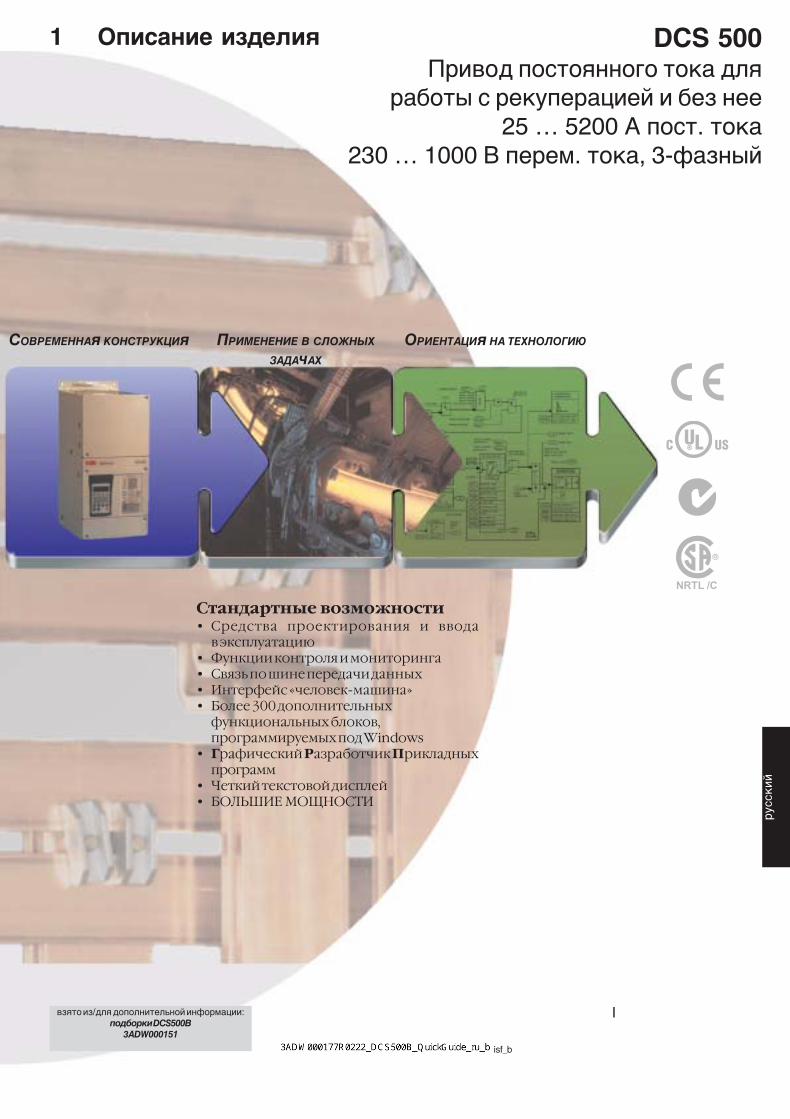
I
рус
ски
й
R
NRTL /C
I
1 Описание изделия
взято из/для дополнительной информации:подборки DCS500B
3ADW000151
DCS 500Привод постоянного тока для
работы с рекуперацией и без нее25 … 5200 А пост. тока
230 … 1000 В перем. тока, 3-фазный
СОВРЕМЕННАя КОНСТРУКЦИя ПРИМЕНЕНИЕ В СЛОЖНЫХ
ЗАДАчАХ
ОРИЕНТАЦИя НА ТЕХНОЛОГИЮ
Стандартные возможности• Средства проектирования и ввода
в эксплуатацию• Функции контроля и мониторинга• Связь по шине передачи данных• Интерфейс «человек!машина»• Более 300 дополнительных
функциональных блоков,программируемых под Windows
• Графический Разработчик Прикладныхпрограмм
• Четкий текстовой дисплей• БОЛЬШИЕ МОЩНОСТИ
3ADW000177R0200_DCS500B_QuickGuide_edisf_b
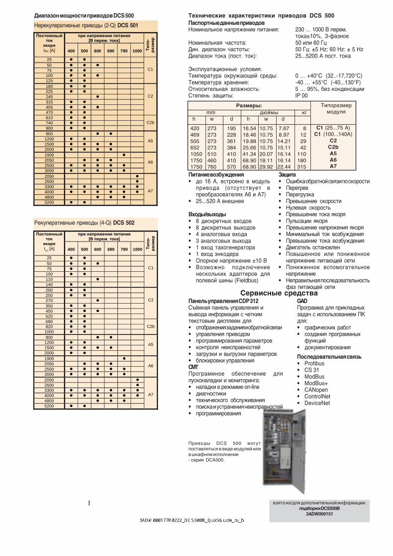
I взято из/для дополнительной информации:подборки DCS500B
3ADW000151
Диапазон мощности приводов DCS 500Паспортные данные приводовНоминальное напряжение питания: 230 … 1000 В перем.
тока±10%, 3-фазноеНоминальная частота: 50 или 60 ГцДин. диапазон частоты: 50 Гц: ±5 Hz; 60 Hz: ± 5 HzДиапазон тока (пост. ток): 25...5200 A пост. тока
Эксплуатационные условия:Температура окружающей среды: 0 … +40°C (32..-17,720°C)Температура хранения: -40 … +55°C (-40...130°F)Относительная влажность: 5 … 95%, без конденсацииСтепень защиты: IP 00
Питание возбуждения• до 16 А, встроено в модуль
привода (отсутствует впреобразователях А6 и А7)
• 25...520 A внешнее
Входы/выходы• 8 дискретных входов• 8 дискретных выходов• 4 аналоговых входа• 3 аналоговых выхода• 1 вход тахогенератора• 1 вход энкодера• Опорное напряжение ±10 В• Возможно подключение
нескольких адаптеров дляполевой шины (Fieldbus)
Защита• Ошибка обратной связи по скорости• Перегрев• Перегрузка• Превышение скорости• Нулевая скорость• Превышение тока якоря• Пульсации якоря• Превышение напряжения якоря• Минимальный ток возбуждения• Превышение тока возбуждения• Двигатель остановлен• Повышенное или пониженное
напряжение питающей сети• Пониженное вспомогательное
напряжение• Неправильная последовательность
фаз питающей сети
Панель управления CDP 312Съёмная панель управления ивывода информации с четкимтекстовым дисплеем для• отображения задания и обратной связи• управления приводом• программирования параметров• контроля неисправностей• загрузки и выгрузки параметров• блокировки управления
Технические характеристики приводов DCS 500
CMTПрограммное обеспечение дляпусконаладки и мониторинга:• наладки в режмиме on-line• диагностики• технического обслуживания• поиска и устранения неисправностей• программирования
Рекуперативные приводы (4-Q) DCS 502
Нерекуперативные приводы (2-Q) DCS 501
GADПрограмма для прикладныхзадач с использованием ПКдля:• графических работ• создания программных
функций• документирования
Сервисные средства
Приводы DCS 500 могутпоставляться в виде модулей илив шкафном исполнении- серия DCA500.
Последовательная связь• Profibus• CS 31• ModBus• ModBus+• CANopen• ControlNet• DeviceNet
при напряжении питания [В перем. тока]
Постоянный ток якоря IDC [A]
400
500
600
690
790
1000 Ти
по-
размер
25 ! ! 50 ! ! ! 75 ! ! 100 ! ! ! 125 ! !
C1
180 ! ! 225 ! ! 245 ! 315 ! ! 405 ! ! ! 470 ! !
C2
610 ! ! 740 ! ! 900 ! !
C2b
900 ! ! 1200 ! ! 1500 ! ! ! ! 2000 ! ! ! !
A5
1900 ! 2050 ! ! ! 2500 ! ! ! ! ! 3000 ! ! ! ! !
A6
2050 ! 2600 ! 3300 ! ! ! ! ! ! 4000 ! ! ! ! ! ! 4800 ! ! ! 5200 ! !
A7
при напряжении питания [В перем. тока]
Постоянный ток якоря IDC [A]
400
500
600
690
790
1000 Ти
по-
размер
25 ! ! 50 ! ! ! 75 ! !
100 ! ! 110 ! 140 ! !
C1
200 ! ! 250 ! ! 270 ! 350 ! ! 450 ! ! ! 520 ! !
C2
680 ! ! 820 ! !
1000 ! !
C2b
900 ! ! 1200 ! ! 1500 ! ! ! ! 2000 ! !
A5
1900 ! 2050 ! ! ! 2500 ! ! ! ! ! 3000 ! ! ! ! !
A6
2050 ! 2600 ! 3300 ! ! ! ! ! ! 4000 ! ! ! ! ! ! 4800 ! ! ! 5200 ! !
A7
Типоразмермодуля
C1 (25...75 A)C1 (100...140A)
C2C2bA5A6A7
Размеры:mm дюймы кг
h w d h w d
420 273 195 16.54 10.75 7.67 8469 273 228 18.46 10.75 8.97 12505 273 361 19.88 10.75 14.21 29652 273 384 25.66 10.75 15.11 421050 510 410 41.34 20.07 16.14 1101750 460 410 68.90 18.11 16.14 1801750 760 570 68.90 29.92 22.44 315
I
рус
ски
й
2 Замечания, краткие указания для CD и обзор документации
Мы рады, что Вы приобрели привод АВВ дляуправления двигателями постоянного тока, имы благодарны Вам за проявленное доверие кнашей продукции.
Для того, чтобы наше изделие принесло Вамнаибольшую пользу, мы приложили к нему этуброшюру. Она предназначена, главным образом,для того, чтобы дать краткий обзор основныхданных изделия, в ней приводятся указания поЭМС, типичные применения, рассматриваетсязапуск устройства, а также поиск и устранениенеисправностей.
Если Вам потребуется дальнейшая информацияпо изделию, то в дополнение к этой краткойдокументации у Вас имеется CD-ROM (компакт-диск является составной частью комплектадокументации) на пяти основных языках:английском, немецком, итальянском, испанскоми французском, в котором приведена следующаяинформация.
Документация
Документация на наши изделия серий• DCS400• DCS500• DCS600
Наша документация, в основном,структурирована следующим образом.
Описание устройства,в котором приведены исчерпывающие сведенияпо всей системе привода.
Технические характеристикив виде подробных сведений обо всех важныхдеталях конкретных элементов, в том числехарактеристики модулей, электронные платы,вентиляторы и вспомогательные устройства.
Инструкция по эксплуатациисо всей необходимой и детальной информациейпо запуску и техническому обслуживанию всегопривода.
Описание программы и блоков приложенийнеобходимое только для программированияпривода, поставляемое только на англ. яз. и нев печатном виде.
Сервисное руководстводля технического обслуживания и ремонтаблоков
Кроме того, дополнительная информация поприменению (например, 12-пульсная схема) идополнительные технические средства и т. д.
Системные требования дляиспользования CD-ROM
• Операционная система WINDOWS 98, NT,2000, XP
• ACROBAT READER 4.0 достаточно(рекомендуется версия 5.0, записанная наCD-ROM)
• INTERNET Explorer 5.0 или более новаяверсия
Если CD ROM не запускается автоматически,щелкните дважды по START.HTM
Дальнейшая поддержка продукта
Кроме того, мы обеспечиваем поддержкупродукта, если Вы, как заказчик, выполняетенаши условия и пришли к выводу, что мыудовлетворяем Вашим требованиям.
InternetНа сайте АВВ
www.abb.com/dc
вы найдете много информации об• изделиях постоянного тока• сервисной поддержке• последних изменениях• сервисных программных средствах• загрузке программ и т. д.Пожалуйста, посещайте наш сайт.
Связь с намиЕсли Вам необходима какая-либодополнительная информация, обращайтесь вближайший офис ABB или посылайте нам запроспо электронной почте:
[email protected]@ru.abb.com
Будьте любезны сообщить Вашу фамилию,компанию, адрес и номер телефона, и мы сразуже укажем Вам имя контактного лица,ответственного за решение Ваших вопросов.
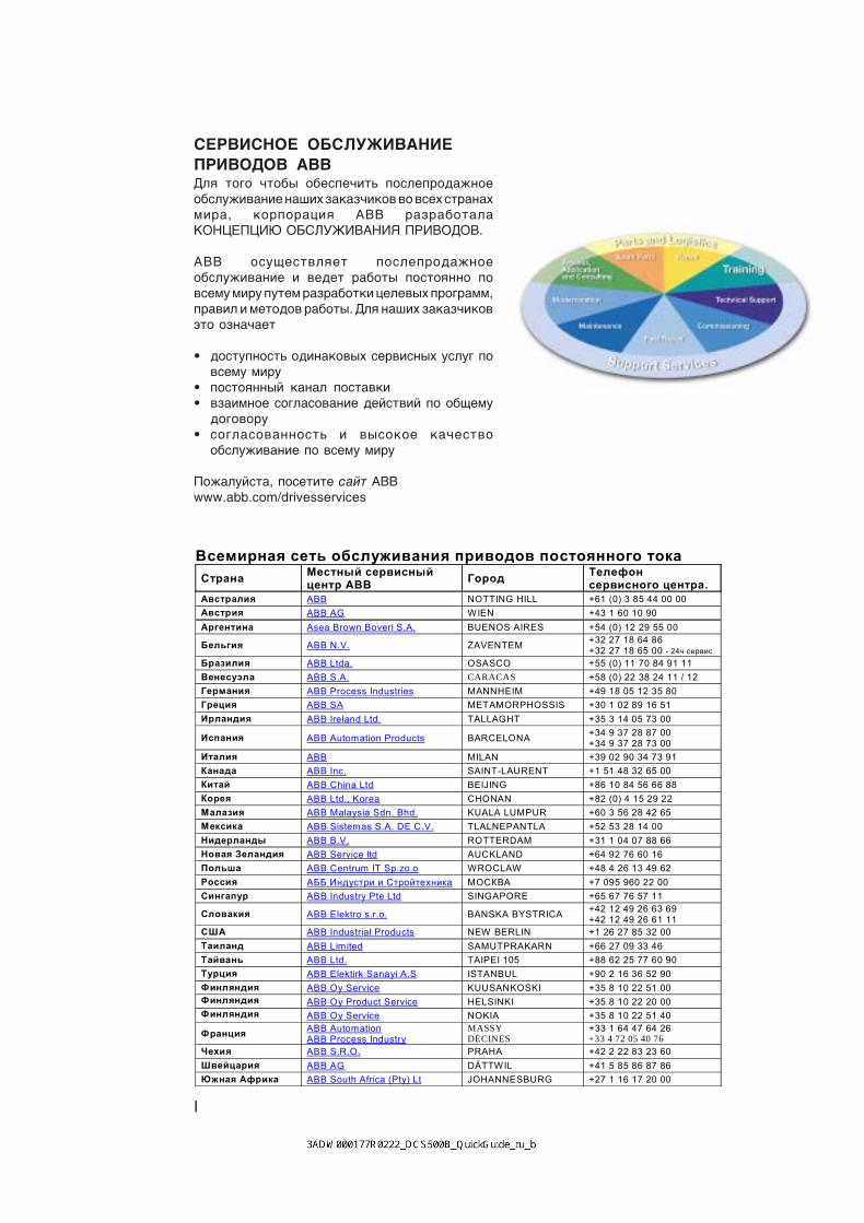
I
СЕРВИСНОЕ ОБСЛУЖИВАНИЕПРИВОДОВ АВВДля того чтобы обеспечить послепродажноеобслуживание наших заказчиков во всех странахмира, корпорация АВВ разработалаКОНЦЕПЦИЮ ОБСЛУЖИВАНИЯ ПРИВОДОВ.
АВВ осуществляет послепродажноеобслуживание и ведет работы постоянно повсему миру путем разработки целевых программ,правил и методов работы. Для наших заказчиковэто означает
• доступность одинаковых сервисных услуг повсему миру
• постоянный канал поставки• взаимное согласование действий по общему
договору• согласованность и высокое качество
обслуживание по всему миру
Пожалуйста, посетите сайт АВВwww.abb.com/drivesservices
Всемирная сеть обслуживания приводов постоянного тока
Страна Местный сервисный центр АВВ Город Телефон
сервисного центра. Австралия ABB NOTTING HILL +61 (0) 3 85 44 00 00 Австрия ABB AG WIEN +43 1 60 10 90 Аргентина Asea Brown Boveri S.A. BUENOS AIRES +54 (0) 12 29 55 00
Бельгия ABB N.V. ZAVENTEM +32 27 18 64 86 +32 27 18 65 00 - 24ч сервис
Бразилия ABB Ltda. OSASCO +55 (0) 11 70 84 91 11 Венесуэла ABB S.A. CARACAS +58 (0) 22 38 24 11 / 12 Германия ABB Process Industries MANNHEIM +49 18 05 12 35 80 Греция ABB SA METAMORPHOSSIS +30 1 02 89 16 51 Ирландия ABB Ireland Ltd. TALLAGHT +35 3 14 05 73 00
Испания ABB Automation Products BARCELONA +34 9 37 28 87 00 +34 9 37 28 73 00
Италия ABB MILAN +39 02 90 34 73 91 Канада ABB Inc. SAINT-LAURENT +1 51 48 32 65 00 Китай ABB China Ltd BEIJING +86 10 84 56 66 88 Корея ABB Ltd., Korea CHONAN +82 (0) 4 15 29 22 Малазия ABB Malaysia Sdn. Bhd. KUALA LUMPUR +60 3 56 28 42 65 Мексика ABB Sistemas S.A. DE C.V. TLALNEPANTLA +52 53 28 14 00 Нидерланды ABB B.V. ROTTERDAM +31 1 04 07 88 66 Новая Зеландия ABB Service ltd AUCKLAND +64 92 76 60 16 Польша ABB Centrum IT Sp.zo.o WROCLAW +48 4 26 13 49 62 Россия АББ Индустри и Стройтехника МОСКВА +7 095 960 22 00 Сингапур ABB Industry Pte Ltd SINGAPORE +65 67 76 57 11
Словакия ABB Elektro s.r.o. BANSKA BYSTRICA +42 12 49 26 63 69 +42 12 49 26 61 11
США ABB Industrial Products NEW BERLIN +1 26 27 85 32 00 Таиланд ABB Limited SAMUTPRAKARN +66 27 09 33 46 Тайвань ABB Ltd. TAIPEI 105 +88 62 25 77 60 90 Турция ABB Elektirk Sanayi A.S ISTANBUL +90 2 16 36 52 90 Финляндия ABB Oy Service KUUSANKOSKI +35 8 10 22 51 00 Финляндия ABB Oy Product Service HELSINKI +35 8 10 22 20 00 Финляндия ABB Oy Service NOKIA +35 8 10 22 51 40
Франция ABB Automation ABB Process Industry
MASSY DECINES
+33 1 64 47 64 26 +33 4 72 05 40 76
Чехия ABB S.R.O. PRAHA +42 2 22 83 23 60 Швейцария ABB AG DÄTTWIL +41 5 85 86 87 86 Южная Африка ABB South Africa (Pty) Lt JOHANNESBURG +27 1 16 17 20 00
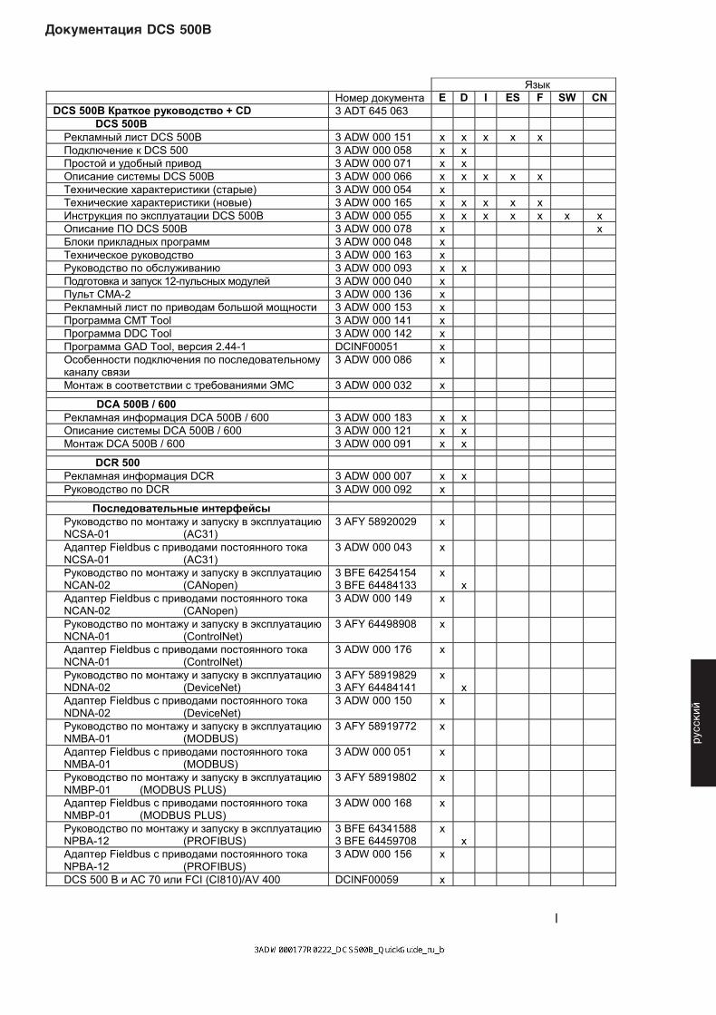
I
рус
ски
й
Документация DCS 500B
Язык Номер документа E D I ES F SW CN DCS 500B Краткое руководство + CD 3 ADT 645 063 DCS 500B Рекламный лист DCS 500B 3 ADW 000 151 x x x x x Подключение к DCS 500 3 ADW 000 058 x x Простой и удобный привод 3 ADW 000 071 x x Описание системы DCS 500B 3 ADW 000 066 x x x x x Технические характеристики (старые) 3 ADW 000 054 x Технические характеристики (новые) 3 ADW 000 165 x x x x x Инструкция по эксплуатации DCS 500B 3 ADW 000 055 x x x x x x x Описание ПО DCS 500B 3 ADW 000 078 x x Блоки прикладных программ 3 ADW 000 048 x Техническое руководство 3 ADW 000 163 x Руководство по обслуживанию 3 ADW 000 093 x x Подготовка и запуск 12-пульсных модулей 3 ADW 000 040 x Пульт CMA-2 3 ADW 000 136 x Рекламный лист по приводам большой мощности 3 ADW 000 153 x Программа CMT Tool 3 ADW 000 141 x Программа DDC Tool 3 ADW 000 142 x Программа GAD Tool, версия 2.44-1 DCINF00051 x Особенности подключения по последовательному каналу связи
3 ADW 000 086 x
Монтаж в соответствии с требованиями ЭМС 3 ADW 000 032 x
DCA 500B / 600 Рекламная информация DCA 500B / 600 3 ADW 000 183 x x Описание системы DCA 500B / 600 3 ADW 000 121 x x Монтаж DCA 500B / 600 3 ADW 000 091 x x
DCR 500 Рекламная информация DCR 3 ADW 000 007 x x Руководство по DCR 3 ADW 000 092 x
Последовательные интерфейсы Руководство по монтажу и запуску в эксплуатацию NCSA-01 (AC31)
3 AFY 58920029 x
Адаптер Fieldbus с приводами постоянного тока NCSA-01 (AC31)
3 ADW 000 043 x
Руководство по монтажу и запуску в эксплуатацию NCAN-02 (CANopen)
3 BFE 64254154 3 BFE 64484133
x x
Адаптер Fieldbus с приводами постоянного тока NCAN-02 (CANopen)
3 ADW 000 149 x
Руководство по монтажу и запуску в эксплуатацию NCNA-01 (ControlNet)
3 AFY 64498908 x
Адаптер Fieldbus с приводами постоянного тока NCNA-01 (ControlNet)
3 ADW 000 176 x
Руководство по монтажу и запуску в эксплуатацию NDNA-02 (DeviceNet)
3 AFY 58919829 3 AFY 64484141
x x
Адаптер Fieldbus с приводами постоянного тока NDNA-02 (DeviceNet)
3 ADW 000 150 x
Руководство по монтажу и запуску в эксплуатацию NMBA-01 (MODBUS)
3 AFY 58919772 x
Адаптер Fieldbus с приводами постоянного тока NMBA-01 (MODBUS)
3 ADW 000 051 x
Руководство по монтажу и запуску в эксплуатацию NMBP-01 (MODBUS PLUS)
3 AFY 58919802 x
Адаптер Fieldbus с приводами постоянного тока NMBP-01 (MODBUS PLUS)
3 ADW 000 168 x
Руководство по монтажу и запуску в эксплуатацию NPBA-12 (PROFIBUS)
3 BFE 64341588 3 BFE 64459708
x x
Адаптер Fieldbus с приводами постоянного тока NPBA-12 (PROFIBUS)
3 ADW 000 156 x
DCS 500 B и AC 70 или FCI (CI810)/AV 400 DCINF00059 x
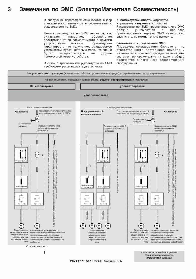
I для дополнительной информации:Техническое руководство3ADW000163 - глава 2.1
Классификация
Не используется
1-е условия эксплуатации (жилая зона, лёгкая промышленная среда) с ограниченным распространением
Не используется, поскольку канал сбыта общего распространения исключен
удовлетворяется
удовлетворяется
В следующих параграфах описывается выборэлектрических элементов в соответствии сруководством по ЭМС.
Целью руководства по ЭМС является, какуказывает название, обеспечениеэлектромагнитной совместимости с другимиустройствами системы. Руководствогарантирует, что излучение, создаваемоеустройством, будет настолько мало, что оно небудет воздействовать на другиепомехоустойчивые устройства.
В связи с требованиями руководства по ЭМСнеобходимо рассматривать два аспекта:
• помехоустойчивость устройства• реальное излучение устройстваРуководство по ЭМС предполагает, что ЭМСдолжна учитываться в процессепроектирования, однако ЭМС невозможнорассчитать, ее можно только измерить.
Замечание по согласованию ЭМСПроцедура согласования базируется наответственности поставщика привода иизготовителя соответствующей машины илисистемы пропорционально их доле в общемколичестве включенного электрическогооборудования.
3 Замечания по ЭМС (ЭлектроМагнитная Совместимость)
MM
Mains filter
Converter
Line reactor
Supply transformer for a residential area (rating normally ≤ 1,2 MVA)
Earthed public 400-V network with neutral conductor
Medium-voltage network
Earthed neutral
To
oth
er
load
s, e
.g. d
rive
sys
tem
s
An isolating transformer with an earthed screen and earthed iron core renders mains filter and line reactor superfluous.
Operation at public low-voltage network
together with other loads of all kinds.
Residential area
To
oth
er
load
s w
hich
hav
e to
be
pro
tect
ed
from
the
syst
em d
istu
rban
ces
caus
ed
by
pow
er c
onv
ert
ers
(HF
inte
rfer
enc
e an
d co
mm
utat
ion
no
tche
s)
Converter
MMMM MM
alte
rnat
ive
alte
rnat
ive
Line reactor + Y-capacitor
Medium-voltage network
Supply transformer for a residential area (rating normally ≤ 1.2 MVA)
Earthed neutral
Earthed public 400-V network with neutral conductor
To
oth
er
load
s, e
.g. d
rive
sys
tem
s
Mains filter
Line reactor
Converter Converter
Mains filter
Line reactor
Converter Converter
An isolating transformer with an earthed screen and earthed iron core renders mains filter and line reactor superfluous.
Operation at public low-voltage network
together with other loads of all kinds.
To
oth
er
load
s, e
.g. d
rive
sys
tem
s
To
oth
er
load
s w
hich
hav
e to
be
pro
tect
ed
from
the
syst
em d
istu
rban
ces
caus
ed
by
pow
er c
onv
ert
ers
(HF
inte
rfer
enc
e an
d co
mm
utat
ion
no
tche
s)
Earthed public 400-V network with neutral conductor
Operation at public low-voltage network together with other loads of all kinds.
Light industry Residential area
Сеть среднего напряжения Сеть среднего напряжения
Жилая зона Трансформатор питания для жилойзоны (обычно мощность < 1,2 MВA)
Заземленная сеть 400 Вобщего пользования снейтралью
Заземленнаянейтраль
К д
р. н
агру
зкам
, нап
рим
ер, к
сис
тем
ам п
риво
дов
К д
р. н
агру
зкам
, кот
оры
е д
олж
ны и
мет
ь за
щит
у от
сис
тем
ных
пом
ех, с
озд
авае
мы
хпр
ивод
ом (
ВЧ
пом
ехи
и к
омм
утац
ионн
ые
импу
льс
ы)
Подключение книзковольтной сетиобщего назначения
вместе с другиминагрузками любого
типа.
Изолирующий трансформатор с
заземленным экраном и заземленнымстальным сердечником, сетевойфильтр для защиты передаваемойинформации и линейный дроссель нетребуются.
Подключение книзковольтной сетиобщего назначениявместе с другими
нагрузками любоготипа.
Подключение книзковольтной сетиобщего назначения
вместе с другиминагрузками любого
типа.
Трансформатор питания для жилойзоны (обычно мощность < 1,2 MВA)
Заземленнаянейтраль
Заземленная сеть 400 Вобщего пользования снейтралью
Заземленная сеть 400 Вобщего пользования снейтралью
Предприятия легкойпромышленности
Жилая зона
Сетевой фильтр
Линейный дроссель
П р и в о д П р и в о д П р и в о д П р и в о д П р и в о д П р и в о д
Линейный дроссель Линейный дроссель
Сетевой фильтр
Линейный дроссель+Y конденсатор
Сетевой фильтр
К д
р. н
агру
зкам
, нап
рим
ер, к
сис
тем
ам п
риво
дов
К д
р. н
агру
зкам
, нап
рим
ер, к
сис
тем
ам п
риво
дов
К д
р. н
агру
зкам
, кот
оры
е д
олж
ны и
мет
ь за
щит
у от
сис
тем
ных
пом
ех, с
озд
авае
мы
хпр
ивод
ом (
ВЧ
пом
ехи
и к
омм
утац
ионн
ые
импу
льс
ы)
по в
ыбо
ру
по в
ыбо
ру
Изолирующий трансформаторс заземленным экраном изаземленным стальнымсердечником, сетевой фильтр длязащиты передаваемой информациии линейный дроссель не требуются.
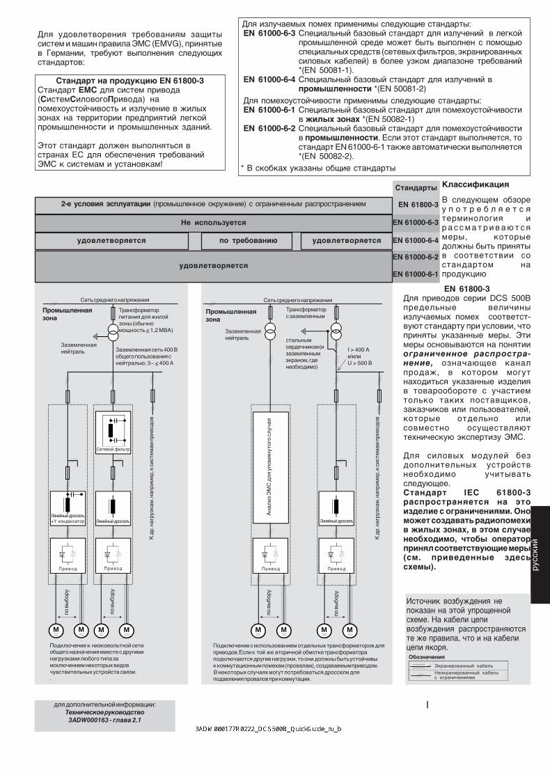
I
рус
ски
й
для дополнительной информации:Техническое руководство3ADW000163 - глава 2.1
удовлетворяется
удовлетворяется
Окружающие условия второго типа (промышленное окружение) с ограниченным
по требованию удовлетворяется
Не используется
Классификация
В следующем обзореу п о т р е б л я е т с ятерминология ир а с с м а т р и в а ю т с ямеры, которыедолжны быть принятыв соответствии состандартом напродукцию
Для удовлетворения требованиям защитысистем и машин правила ЭМС (EMVG), принятыев Германии, требуют выполнения следующихстандартов:
Стандарт на продукцию EN 61800-3Стандарт EMC для систем привода(СистемСиловогоПривода) напомехоустойчивость и излучение в жилыхзонах на территории предприятий легкойпромышленности и промышленных зданий.
Этот стандарт должен выполняться встранах ЕС для обеспечения требованийЭМС к системам и установкам!
Источник возбуждения непоказан на этой упрощеннойсхеме. На кабели цепивозбуждения распространяютсяте же правила, что и на кабелицепи якоря.
EN 61800-3Для приводов серии DCS 500Bпредельные величиныизлучаемых помех соответст-вуют стандарту при условии, чтоприняты указанные меры. Этимеры основываются на понятииограниченное распростра-нение, означающее каналпродаж, в котором могутнаходиться указанные изделияв товарообороте с участиемтолько таких поставщиков,заказчиков или пользователей,которые отдельно илисовместно осуществляюттехническую экспертизу ЭМС.
Для силовых модулей бездополнительных устройствнеобходимо учитыватьследующее.Стандарт IEC 61800-3распространяется на этоизделие с ограничениями. Ономожет создавать радиопомехив жилых зонах, в этом случаенеобходимо, чтобы операторпринял соответствующие меры(см. приведенные здесьсхемы).
MMMM
Supply transformer for a residential area (rating normally ≤ 1.2 MVA)
Earthed 400-V network with neutral conductor; 3~ ≤ 400 A
Operation at low-voltage network together with other loads of all kinds, apart from some kinds of sensitive communication equipment.
To
oth
er
load
s, e
.g. d
rive
sys
tem
s
Line reactor + Y-capacitor Line reactor
Converter Converter
Mains filter
Earthed neutral
Medium-voltage network
Industrial zone
alte
rnat
ive
alte
rnat
ive
MMMM
Convertertransformer
Cas
e-re
fere
nced
EM
C a
naly
sis
alte
rnat
ive
Converter transformer with earthed
iron core (and earthed screen where appropriate)
alte
rnat
ive
I > 400 A and/or U > 500 V
Operation with separate power converter transformer. If there are other loads at the same secondary winding, these must be able to cope with the commutation gaps caused by the power converter. In some cases, commutating reactors will be required.
To
oth
er
load
s, e
.g. d
rive
sys
tem
s
Converter Converter
Line reactor
Medium-voltage network
Industrial zone
Legend
Unscreened cable with restriction
Screened cable
Для излучаемых помех применимы следующие стандарты:EN 61000-6-3 Специальный базовый стандарт для излучений в легкой
промышленной среде может быть выполнен с помощьюспециальных средств (сетевых фильтров, экранированныхсиловых кабелей) в более узком диапазоне требований*(EN 50081-1).
EN 61000-6-4 Специальный базовый стандарт для излучений впромышленности *(EN 50081-2)
Для помехоустойчивости применимы следующие стандарты:EN 61000-6-1 Специальный базовый стандарт для помехоустойчивости
в жилых зонах *(EN 50082-1)EN 61000-6-2 Специальный базовый стандарт для помехоустойчивости
в промышленности. Если этот стандарт выполняется, тостандарт EN 61000-6-1 также автоматически выполняется*(EN 50082-2).
* В скобках указаны общие стандарты
EN 61800-3
EN 61000-6-3
EN 61000-6-4
EN 61000-6-2
EN 61000-6-1
удовлетворяется
удовлетворяется
2-е условия эсплуатации (промышленное окружение) с ограниченным распространением
по требованию удовлетворяется
Не используется
Стандарты
Сеть среднего напряжения Сеть среднего напряжения
Трансформаторпитания для жилойзоны (обычномощность < 1,2 MВA)
Заземленнаянейтраль Заземленная сеть 400 В
общего пользования снейтралью; 3~ < 400 A
Промышленнаязона
Промышленнаязона
П р и в о д П р и в о д П р и в о дП р и в о д
Линейный дроссель Линейный дроссель
Сетевой фильтр
Линейный дроссель+Y конденсатор
К д
р. н
агру
зкам
, нап
рим
ер, к
сис
тем
ам п
риво
дов
К д
р. н
агру
зкам
, нап
рим
ер, к
сис
тем
ам п
риво
дов
Подключение к низковольтной сетиобщего назначения вместе с другиминагрузками любого типа заисключением некоторых видовчувствительных устройств связи..
Подключение с использованием отдельных трансформаторов дляприводов.
Если
к той же вторичной обмотке трансформатора
подключаются другие нагрузки, то они должны быть устойчивы
к коммутационным помехам (провалам), создаваемым приводом.
В некоторых случаях могут потребоваться дроссели дляподавления провалов при коммутации.
Заземленнаянейтраль
Трансформаторс заземленным
стальнымсердечником
(и
заземленнымэкраном, гденеобходимо)
I > 400 Aи/илиU > 500 В
по в
ыбо
ру
по в
ыбо
ру
по в
ыбо
ру
по в
ыбо
ру
Ан
ал
из
ЭМ
С д
ля
уп
ом
ян
уто
го с
луч
ая
Обозначения
Экранированный кабель
Неэкранированный кабельс ограничениями
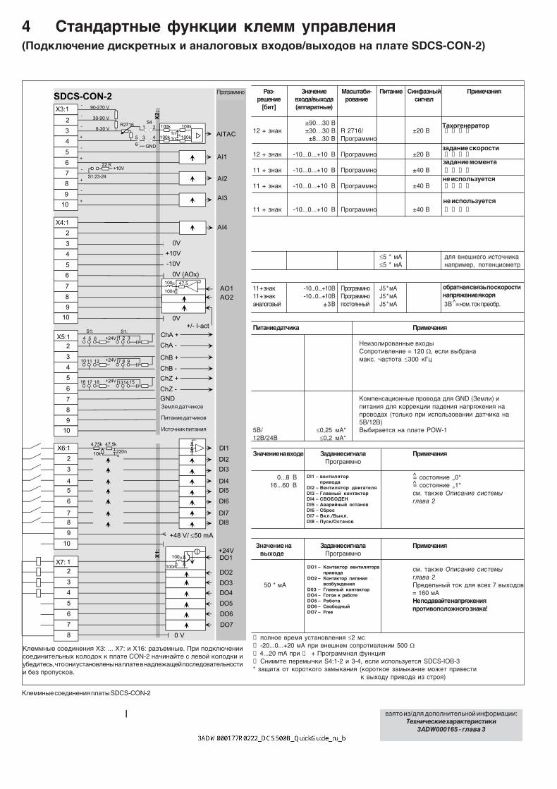
I взято из/для дополнительной информации:Технические характеристики
3ADW000165 - глава 3
4 Стандартные функции клемм управления
Клеммные соединения платы SDCS-CON-2
(Подключение дискретных и аналоговых входов/выходов на плате SDCS-CON-2)
Клеммные соединения Х3: ... X7: и Х16: разъемные. При подключениисоединительных колодок к плате CON-2 начинайте с левой колодки иубедитесь, что они установлены на плате в надлежащей последовательностии без пропусков.
X2:
X1:
AITAC
90-270 V
30-90 V
8-30 V
+24V
AI4
ChA +ChA -
ChB +ChB -ChZ +ChZ -GND
0 V
R2716
+10V
S1:23-24
100µ
+48 V/ ≤50 mA
100k1n1n
100n
100k
100k 100k
Power-Source
Sense GNDSense Power +
0V
AI2
AI3
AI1-
+
-
+
-
+
-
-
-
+
AO1AO2
+/- I-act
47.5100µ
100n
0V (AOx)
+10V0V
-10V
DI1
DI2DI3
DI4DI5DI6
DI7DI8
47.5k220n10k
4.75k
DO4DO5
DO7
DO1
DO2DO3
DO6
22 K
345
87
6
7
9
X6:1 2 3
4 5 6
7 8
10
4 5
7
1 2 3
6
4
23
65
910
89
10
2
45
7
23
6
89
10
8
X3:1
X4:1
X5:1
X7:
SDCS-CON-2 Software
+24V 7 8 910 11 12
+24V 13141516 17 18
+24V4 5 6S1:
1 2 3S1:
GND
1 2
3 456
S4
Раз- Значение Масштаби- Питание Синфазный Примечаниярешение входа/выхода рование сигнал
[бит] (аппаратные)
±90…30 В12 + знак ±30…30 В R 2716/ ±20 В ➀ ➁ ➂ ➃
±8…30 В Программно
12 + знак -10...0...+10 В Программно ±20 В ➀ ➁ ➂ ➃
11 + знак -10...0...+10 В Программно ±40 В ➀ ➁ ➂ ➃
11 + знак -10...0...+10 В Программно ±40 В ➀ ➁ ➂ ➃
11 + знак -10...0...+10 В Программно ±40 В ➀ ➁ ➂ ➃
≤5 * мА для внешнего источника≤5 * мА например, потенциометр
11 + знак -10...0...+10 В Программно Ј5 * мА11 + знак -10...0...+10 В Программно Ј5 * мАаналоговый ± 3 В постоянный Ј5 * мА 3 В = ном. ток преобр.
Питание датчика Примечания
Неизолированные входыСопротивление = 120 Ω, если выбранамакс. частота ≤300 кГц
Компенсационные провода для GND (Земли) ипитания для коррекции падения напряжения напроводах (только при использовании датчика на5В/12В)
5В/ ≤0,25 мА* Выбирается на плате POW-112В/24В ≤0,2 мА*
Значение на входе Задание сигнала ПримечанияПрограммно
0...8 В = состояние „0“16...60 В = состояние „1“
см. также Описание системыглава 2
Значение на Задание сигнала Примечания выходе Программно
см. также Описание системыглава 2
50 * мA Предельный ток для всех 7 выходов= 160 мАНе подавайте напряженияпротивоположного знака!
➀ полное время установления ≤2 мс➁ -20...0...+20 мA при внешнем сопротивлении 500 Ω➂ 4...20 mA при ➁ + Программная функция➃ Снимите перемычки S4:1-2 и 3-4, если используется SDCS-IOB-3* защита от короткого замыкания (короткое замыкание может привести
к выходу привода из строя)
задание скорости
Тахогенератор
задание момента
не используется
не используется
обратная связь по скоростинапряжение якоря
DI1 – вентиляторпривода
DI2 – Вентилятор двигателяDI3 – Главный контакторDI4 – СВОБОДЕНDI5 – Аварийный остановDI6 – СбросDI7 – Вкл./Выкл.DI8 – Пуск/Останов
DO1 – Контактор вентиляторапривода
DO2 – Контактор питаниявозбуждения
D03 – Главный контакторDO4 – Готов к работеDO5 – РаботаDO6 – СвободныйDO7 – Free
Программно
Земля датчиков
Питание датчиков
Источник питания
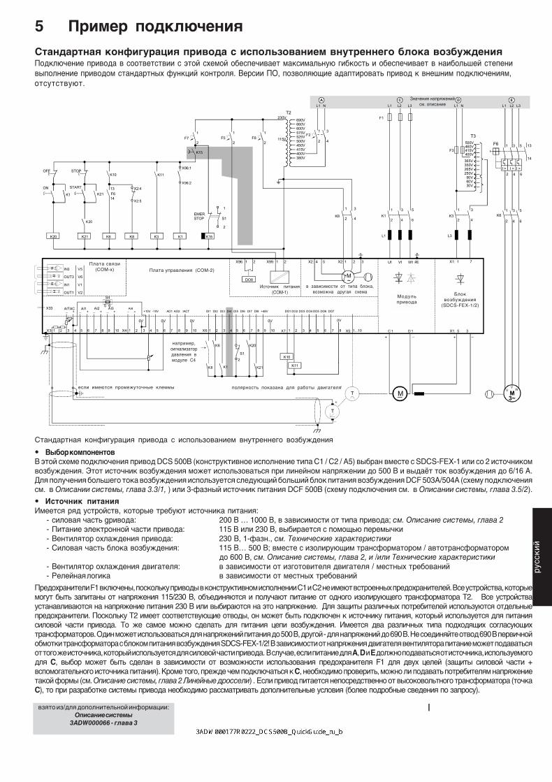
I
рус
ски
й
5 Пример подключения
взято из/для дополнительной информации:Описание системы
3ADW000066 - глава 3
Стандартная конфигурация привода с использованием внутреннего возбуждения
Стандартная конфигурация привода с использованием внутреннего блока возбужденияПодключение привода в соответствии с этой схемой обеспечивает максимальную гибкость и обеспечивает в наибольшей степенивыполнение приводом стандартных функций контроля. Версии ПО, позволяющие адаптировать привод к внешним подключениям,отсутствуют.
• Выбор компонентовВ этой схеме подключения привод DCS 500B (конструктивное исполнение типа C1 / C2 / A5) выбран вместе с SDCS-FEX-1 или со 2 источникомвозбуждения. Этот источник возбуждения может использоваться при линейном напряжении до 500 В и выдаёт ток возбуждения до 6/16 А.Для получения большего тока возбуждения используется следующий больший блок питания возбуждения DCF 503A/504A (схему подключениясм. в Описании системы, глава 3.3/1, ) или 3-фазный источник питания DCF 500B (схему подключения см. в Описании системы, глава 3.5/2).
• Источник питанияИмеется ряд устройств, которые требуют источника питания:
- силовая часть gривода: 200 В … 1000 В, в зависимости от типа привода; см. Описание системы, глава 2- Питание электронной части привода: 115 В или 230 В, выбирается с помощью перемычки- Вентилятор охлаждения привода: 230 В, 1-фазн., см. Технические характеристики- Силовая часть блока возбуждения: 115 В… 500 В; вместе с изолирующим трансформатором / автотрансформатором
до 600 В, см. Описание системы, глава 2, и /или Технические характеристики- Вентилятор охлаждения двигателя: в зависимости от изготовителя двигателя / местных требований- Релейная логика в зависимости от местных требований
Предохранители F1 включены, поскольку приводы в конструктивном исполнении С1 и С2 не имеют встроенных предохранителей. Все устройства, которыемогут быть запитаны от напряжения 115/230 В, объединяются и получают питание от одного изолирующего трансформатора Т2. Все устройстваустанавливаются на напряжение питания 230 В или выбираются на это напряжение. Для защиты различных потребителей используются отдельныепредохранители. Поскольку Т2 имеет соответствующие отводы, он может быть подключен к источнику питания, который используется для питаниясиловой части привода. То же самое можно сделать для питания цепи возбуждения. Имеется два различных типа подходящих согласующихтрансформаторов. Один может использоваться для напряжений питания до 500 В, другой - для напряжений до 690 В. Не соединяйте отвод 690 В первичнойобмотки трансформатора с блоком питания возбуждения SDCS-FEX-1/2! В зависимости от напряжения двигателя вентилятора питание может подаватьсяот того же источника, который используется для силовой части привода. В случае, если питание для A, D и E должно подаваться от источника, используемогодля C, выбор может быть сделан в зависимости от возможности использования предохранителя F1 для двух целей (защиты силовой части +вспомогательного источника питания). Кроме того, прежде чем подключаться к C, необходимо проверить, можно ли подавать потребителям напряжениетакой формы (см. Описание системы, глава 2 Линейные дроссели) . Если привод питается непосредственно от высоковольтного трансформатора (точкаC), то при разработке системы привода необходимо рассматривать дополнительные условия (более подробные сведения по запросу).
IN3
OUT3
IN1
OUT1
V5
V6
V1
V2
X96:
DO8
1 2 X99: 1 2 X2: 4 5 X2: 1 2 3 U1 W1V1 PE
K1 F6
K20
K21K20 K3 K1
X96:1
X96:2
L1 L2 L3
F1
F3
K31 3
2 4
M~
T3F23
4
1
2
T2690V660V600V575V525V500V450V415V400V380V
115V
230V
K15
K15
S1
1
2
K6 K8
X2:4
X2:5
K11K10
K21
500V460V415V400V
365V350V265V250V90V60V30V
X33
C 1 D 1
AITAC AI1 AI2 AI3 AI4+10V -10V AO1 AO2 IACT DI1 DI2 DI3 DI4 DI5 DI6 DI7 DI8 +48V DO1 DO2 DO3 DO4 DO5 DO6 DO7_ _ _ _ _+ + + + +
T
T M
0V0V0V0V0V
X3: 1 2 3 4 5 6 7 8 9 10 X4: 1 2 3 4 5 6 7 8 9 10 X6: 1 2 3 4 5 6 7 8 9 10 X7: 1 2 3 4 5 6 7 8 1...10X5:+ _
+
_
K1
K20
K21
K6
K8
1
2
S1
K11
K10
S4
5 6
2 4 6
1 3 5K6
F51
2F8
1
2F7
1
2
2
1
4
3
6
5F6
I > I > I >
13
14
UV
WM3~
K11 3 5
2 4 6
L1
1
2
3
4K8
13
14
X1: 1 7
L3
X1: 5 3
+ _
L1 N L1 N L1 L2 L3
Voltage levelssee description
A C D E
Communication board (COM-x) Control board (CON-2)
Power supply(POW-1)
Convertermodule
ON
OFF STOP
START
EMER.STOP
Field exciter unit(SDCS-FEX-1/2)
depending on the unit typean other configuration is possible
the polarities are shown for motor operationif there are intermediate terminals
e.g. Pressure switch at C4
module
Значения напряженийсм. описание
Плата связи
(COM-x) Плата управления (COM-2)
Источник питания(COM-1)
в зависимости от типа блока,возможна другая схема
Модульпривода
Блоквозбуждения
(SDCS-FEX-1/2)
например,сигнализатордавления вмодуле С4
если имеются промежуточные клеммы полярность показана для работы двигателя
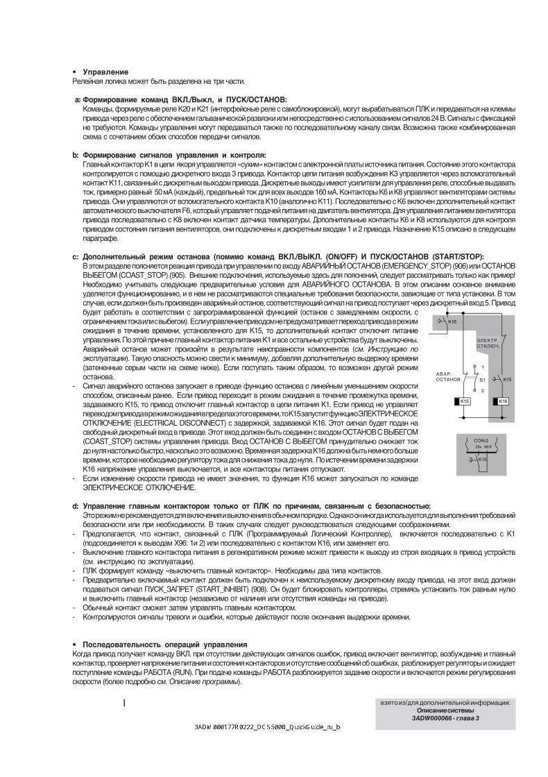
I взято из/для дополнительной информации:Описание системы
3ADW000066 - глава 3
• УправлениеРелейная логика может быть разделена на три части.
a: Формирование команд ВКЛ./Выкл, и ПУСК/ОСТАНОВ:Команды, формируемые реле К20 и К21 (интерфейсные реле с самоблокировкой), могут вырабатываться ПЛК и передаваться на клеммыпривода через реле с обеспечением гальванической развязки или непосредственно с использованием сигналов 24 В. Сигналы с фиксациейне требуются. Команды управления могут передаваться также по последовательному каналу связи. Возможна также комбинированнаясхема с сочетанием обоих способов передачи сигналов.
b: Формирование сигналов управления и контроля:Главный контактор К1 в цепи якоря управляется «сухим» контактом с электронной платы источника питания. Состояние этого контактораконтролируется с помощью дискретного входа 3 привода. Контактор цепи питания возбуждения К3 управляется через вспомогательныйконтакт К11, связанный с дискретным выходом привода. Дискретные выходы имеют усилители для управления реле, способные выдаватьток, примерно равный 50 мА (каждый), предельный ток для всех выходов 160 мА. Контакторы К6 и К8 управляют вентиляторами системыпривода. Они управляются от вспомогательного контакта К10 (аналогично К11). Последовательно с К6 включен дополнительный контактавтоматического выключателя F6, который управляет подачей питания на двигатель вентилятора. Для управления питанием вентиляторапривода последовательно с К8 включен контакт датчика температуры. Дополнительные контакты К6 и К8 используются для контроляприводом состояния питания вентиляторов, они подключены к дискретным входам 1 и 2 привода. Назначение К15 описано в следующемпараграфе.
c: Дополнительный режим останова (помимо команд ВКЛ./ВЫКЛ. (ON/OFF) И ПУСК/ОСТАНОВ (START/STOP):В этом разделе поясняется реакция привода при управлении по входу АВАРИЙНЫЙ ОСТАНОВ (EMERGENCY_STOP) (906) или ОСТАНОВВЫБЕГОМ (COAST_STOP) (905). Внешние подключения, используемые здесь для пояснений, следует рассматривать только как пример!Необходимо учитывать следующие предварительные условия для АВАРИЙНОГО ОСТАНОВА. В этом описании основное вниманиеуделяется функционированию, и в нем не рассматриваются специальные требования безопасности, зависящие от типа установки. В томслучае, если должен быть произведен аварийный останов, соответствующий сигнал на привод поступает через дискретный вход 5. Приводбудет работать в соответствии с запрограммированной функцией (останов с замедлением скорости, сограничением тока или с выбегом). Если управление приводом не предусматривает переход привода в режиможидания в течение времени, установленного для К15, то дополнительный контакт отключит питаниеуправления. По этой причине главный контактор питания К1 и все остальные устройства будут выключены.Аварийный останов может произойти в результате неисправности компонентов (см. Инструкцию поэксплуатации). Такую опасность можно свести к минимуму, добавляя дополнительную выдержку времени(затененные серым части на схеме ниже). Если поступать таким образом, то возможен другой режимостанова.
- Сигнал аварийного останова запускает в приводе функцию останова с линейным уменьшением скоростиспособом, описанным ранее. Если привод переходит в режим ожидания в течение промежутка времени,задаваемого К15, то привод отключит главный контактор в цепи питания К1. Если привод не управляетпереводом привода в режим ожидания в пределах этого времени, то К15 запустит функцию ЭЛЕКТРИЧЕСКОЕОТКЛЮЧЕНИЕ (ELECTRICAL DISCONNECT) с задержкой, задаваемой К16. Этот сигнал будет подан насвободный дискретный вход в приводе. Этот вход должен быть соединен с входом ОСТАНОВ С ВЫБЕГОМ(COAST_STOP) системы управления привода. Вход ОСТАНОВ С ВЫБЕГОМ принудительно снижает токдо нуля настолько быстро, насколько это возможно. Временная задержка К16 должна быть немного большевремени, которое необходимо регулятору тока для снижения тока до нуля. По истечении времени задержкиК16 напряжение управления выключается, и все контакторы питания отпускают.
- Если изменение скорости привода не имеет значения, то функция К16 может запускаться по командеЭЛЕКТРИЧЕСКОЕ ОТКЛЮЧЕНИЕ.
d: Управление главным контактором только от ПЛК по причинам, связанным с безопасностью:Это режим не рекомендуется для включения и выключения в обычном порядке. Однако он иногда используется для выполнения требованийбезопасности или при необходимости. В таких случаях следует руководствоваться следующими соображениями.
- Предполагается, что контакт, связанный с ПЛК (Программируемый Логический Контроллер), включается последовательно с К1(подсоединяется к выводам Х96: 1и 2) или последовательно с контактом К16, или заменяет его.
- Выключение главного контактора питания в регенеративном режиме может привести к выходу из строя входящих в привод устройств(см. инструкцию по эксплуатации).
- ПЛК формирует команду «выключить главный контактор». Необходимы два типа контактов.- Предварительно включаемый контакт должен быть подключен к неиспользуемому дискретному входу привода, на этот вход должен
подаваться сигнал ПУСК_ЗАПРЕТ (START_INHIBIT) (908). Он будет блокировать контроллеры, стремясь установить ток равным нулюи выключить главный контактор (независимо от наличия или отсутствия команды на приводе).
- Обычный контакт сможет затем управлять главным контактором.- Контролируются сигналы тревоги и ошибки, которые действуют после окончания выдержки времени.
• Последовательность операций управленияКогда привод получает команду ВКЛ. при отсутствии действующих сигналов ошибок, привод включает вентилятор, возбуждение и главныйконтактор, проверяет напряжение питания и состояния контакторов и отсутствие сообщений об ошибках, разблокирует регуляторы и ожидаетпоступление команды РАБОТА (RUN). При подаче команды РАБОТА разблокируется задание скорости и включается режим регулированияскорости (более подробно см. Описание программы).
EMER.STOP
K16
K15 K16
K15
ELEC.DISCONN.
DIx
K15
X6:9CON-2
S1
1
2
ЭЛЕКТР.ОТКЛЮЧ.
АВАР.ОСТАНОВ.
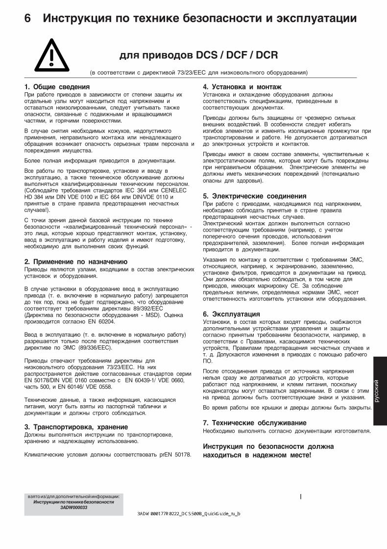
I
рус
ски
й
1. Общие сведенияПри работе приводов в зависимости от степени защиты ихотдельные узлы могут находиться под напряжением иоставаться неизолированными, следует учитывать такжеопасности, связанные с подвижными и вращающимисячастями, и горячими поверхностями.
В случае снятия необходимых кожухов, недопустимогоприменения, неправильного монтажа или ненадлежащегообращения возникает опасность серьезных травм персонала иповреждения имущества.
Более полная информация приводится в документации.
Все работы по транспортировке, установке и вводу вэксплуатацию, а также техническое обслуживание должнывыполняться квалифицированным техническим персоналом.(Соблюдайте требования стандартов IEC 364 или CENELECHD 384 или DIN VDE 0100 и IEC 664 или DIN/VDE 0110 ипринятые в стране правила предотвращения несчастныхслучаев!).
С точки зрения данной базовой инструкции по техникебезопасности «квалифицированный технический персонал» -это лица, которые хорошо представляют монтаж, установку,ввод в эксплуатацию и работу изделия и имеют подготовку,необходимую для выполнения своих функций.
2. Применение по назначениюПриводы являются узлами, входящими в состав электрическихустановок и оборудования.
В случае установки в оборудование ввод в эксплуатациюпривода (т. е. включение в нормальную работу) запрещаетсядо тех пор, пока не будет подтверждено, что оборудованиесоответствует требованиям директивы 89/392/EEC(Директива по безопасности оборудования - MSD). Оценкапроизводится согласно EN 60204.
Ввод в эксплуатацию (т. е. включение в нормальную работу)разрешается только после подтверждения соответствиядирективе по ЭМС (89/336/EEC).
Приводы отвечают требованиям директивы длянизковольтного оборудования 73/23/EEC. На нихраспространяется действие согласованных стандартов серииEN 50178/DIN VDE 0160 совместно с EN 60439-1/ VDE 0660,часть 500, и EN 60146/ VDE 0558.
Технические данные, а также информация, касающаясяпитания, могут быть взяты из паспортной таблички идокументации и должны строго соблюдаться.
3. Транспортировка, хранениеДолжны выполняться инструкции по транспортировке,хранению и надлежащему использованию.
Климатические условия должны соответствовать prEN 50178.
4. Установка и монтажУстановка и охлаждение оборудования должнысоответствовать спецификациям, приведенным всоответствующих документах.
Приводы должны быть защищены от чрезмерно сильныхвнешних воздействий. В особенности следует избегатьизгибов элементов и изменять изоляционные промежутки притранспортировании и работе. Не допускается дотрагиватьсядо электронных устройств и контактов.
Приводы имеют в своем составе элементы, чувствительные кэлектростатическим полям, которые могут быть поврежденыпри неправильном обращении. Электрические элементы недолжны иметь механических повреждений (потенциальноопасны для здоровья).
5. Электрические соединенияПри работе с приводами, находящимися под напряжением,необходимо соблюдать принятые в стране правилапредотвращения несчастных случаев.Электрический монтаж должен выполняться согласносоответствующим требованиям (например, с учетомпоперечного сечения проводов, использованияпредохранителей, заземления). Более полная информацияприводится в документации.
Указания по монтажу в соответствии с требованиями ЭМС,относящиеся, например, к экранированию, заземлению,установке фильтров, приводятся в документации на привод.Они должны обязательно соблюдаться, в том числе дляприводов, имеющих маркировку СЕ. За соблюдениепредельных величин, определяемых нормами ЭМС, несетответственность изготовитель установки или оборудования.
6. ЭксплуатацияУстановки, в состав которых входят приводы, снабжаютсядополнительными устройствами управления и защитысогласно принятым требованиям безопасности, например, всоответствии с Правилами, касающимися техническихустройств, Правилами предотвращения несчастных случаев ит. д. Допускаются изменения в приводах с помощью рабочегоПО.
После отсоединения привода от источника напряжениянельзя сразу же дотрагиваться до устройств, которыеработают под напряжением, и клемм питания, посколькуконденсаторы могут оставаться заряженными. В связи с этимна привод должны быть соответствующие знаки и указания.
Во время работы все крышки и дверцы должны быть закрыты.
7. Технические обслуживаниеНеобходимо выполнять согласно документации изготовителя.
Инструкция по безопасности должнанаходиться в надежном месте!
6 Инструкция по технике безопасности и эксплуатации
для приводов DCS / DCF / DCR
(в соответствии с директивой 73/23/ЕЕС для низковольтного оборудования)
взято из/для дополнительной информации:Инструкции по технике безопасности
3ADW000033
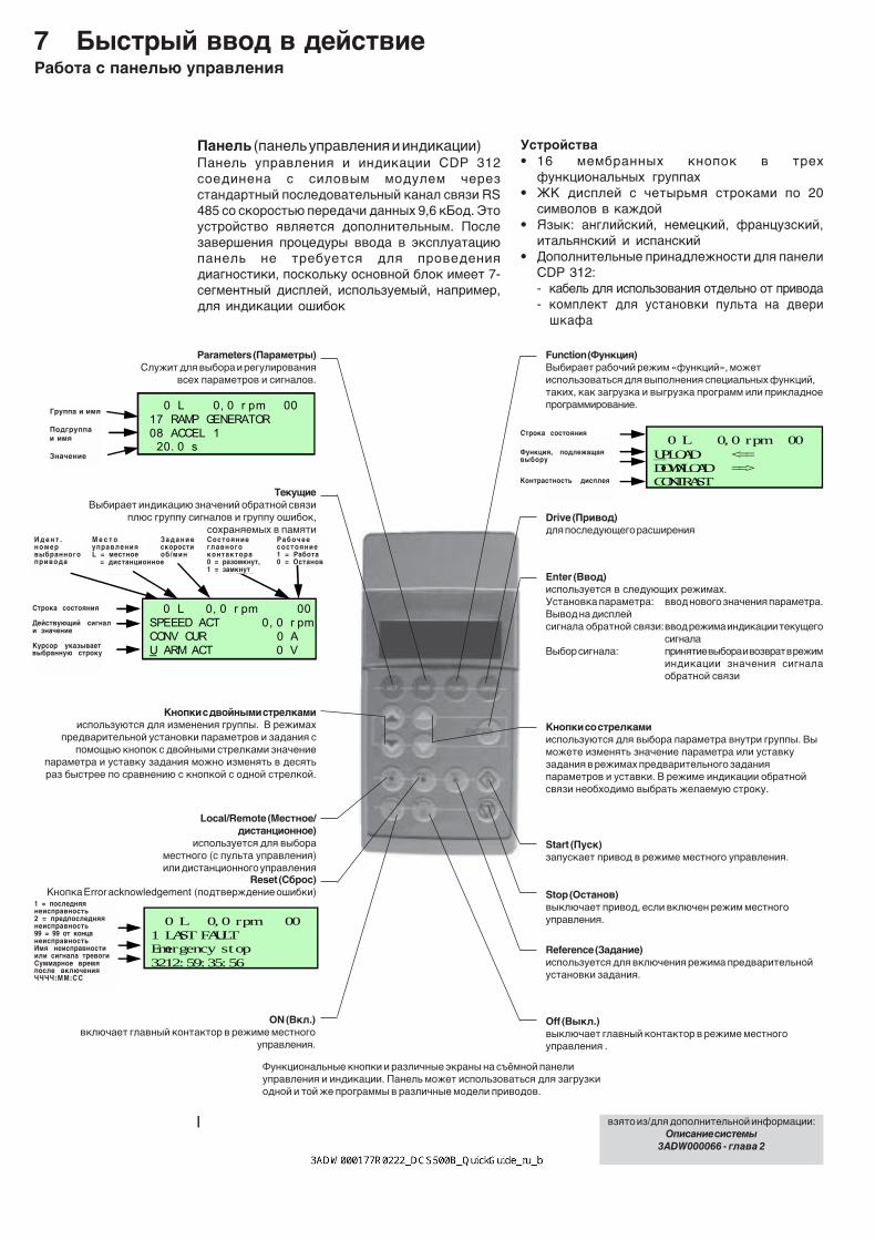
I
7 Быстрый ввод в действиеРабота с панелью управления
Панель (панель управления и индикации)Панель управления и индикации CDP 312соединена с силовым модулем черезстандартный последовательный канал связи RS485 со скоростью передачи данных 9,6 кБод. Этоустройство является дополнительным. Послезавершения процедуры ввода в эксплуатациюпанель не требуется для проведениядиагностики, поскольку основной блок имеет 7-сегментный дисплей, используемый, например,для индикации ошибок
Функциональные кнопки и различные экраны на съёмной панелиуправления и индикации. Панель может использоваться для загрузкиодной и той же программы в различные модели приводов.
ТекущиеВыбирает индикацию значений обратной связи
плюс группу сигналов и группу ошибок,сохраняемых в памяти
Parameters (Параметры)Служит для выбора и регулирования
всех параметров и сигналов.
Function (Функция)Выбирает рабочий режим «функций», можетиспользоваться для выполнения специальных функций,таких, как загрузка и выгрузка программ или прикладноепрограммирование.
Drive (Привод)для последующего расширения
Кнопки с двойными стрелкамииспользуются для изменения группы. В режимах
предварительной установки параметров и задания спомощью кнопок с двойными стрелками значение
параметра и уставку задания можно изменять в десятьраз быстрее по сравнению с кнопкой с одной стрелкой.
Кнопки со стрелкамииспользуются для выбора параметра внутри группы. Выможете изменять значение параметра или уставкузадания в режимах предварительного заданияпараметров и уставки. В режиме индикации обратнойсвязи необходимо выбрать желаемую строку.
Enter (Ввод)используется в следующих режимах.Установка параметра: ввод нового значения параметра.Вывод на дисплейсигнала обратной связи:ввод режима индикации текущего
сигналаВыбор сигнала: принятие выбора и возврат в режим
индикации значения сигналаобратной связи
Local/Remote (Местное/дистанционное)
используется для выбораместного (с пульта управления)или дистанционного управления
Reset (Сброс)Кнопка Error acknowledgement (подтверждение ошибки)
Reference (Задание)используется для включения режима предварительнойустановки задания.
Start (Пуск)запускает привод в режиме местного управления.
Stop (Останов)выключает привод, если включен режим местногоуправления.
ON (Вкл.)включает главный контактор в режиме местного
управления.
Off (Выкл.)выключает главный контактор в режиме местногоуправления .
Устройства• 16 мембранных кнопок в трех
функциональных группах• ЖК дисплей с четырьмя строками по 20
символов в каждой• Язык: английский, немецкий, французский,
итальянский и испанский• Дополнительные принадлежности для панели
CDP 312:- кабель для использования отдельно от привода- комплект для установки пульта на двери
шкафа
0 L 0, 0 rpm 001 LAST FAULTEmergency stop3212:59:35:56
1 = last fault2 = last-but-one fault99 = last-but-98 fault
Total time afterswitch-on HHHH:MM:SS.ss
Name of Fault or alarm
Status row
Functions to be selected
Display contrastsetting
0 L 0, 0 rpm 00UPLOAD <==DOWNLOAD ==>CONTRAST
Groupand nameSubgroupand name
0 L 0, 0 r pm 0017 RAMP GENERATOR08 ACCEL 1 20. 0 s
Value
ID number of thedriveselected
ControllocationL = local = remote
Main contactorstatus0 = open1 = closed
Speedreferencerpm
Run status1 = Run0 = Stop
Status row
Actual signalname and value
Cursor showsthe row selected
0 L 0, 0 r pm 00SPEEED ACT 0, 0 r pmCONV CUR 0 AU ARM ACT 0 V
взято из/для дополнительной информации:Описание системы
3ADW000066 - глава 2
Группа и имя
Подгруппаи имя
Значение
И д е н т .номервыбранногопривода
М е с т оуправленияL = местное = дистанционное
З а д а н и ескоростиоб/мин
Состояниеглавногоконтактора0 = разомкнут,1 = замкнут
Р а б о ч е есостояние1 = Работа0 = Останов
Строка состояния
Действующий сигнали значение
Курсор указываетвыбранную строку
1 = последняянеисправность2 = предпоследняянеисправность99 = 99 от концанеисправностьИмя неисправностиили сигнала тревогиСуммарное времяпосле включенияЧЧЧЧ:ММ:СС
Строка состояния
Функция, подлежащаявыбору
Контрастность дисплея
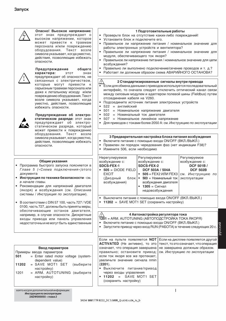
I
рус
ски
й
Запуск
взято из/для дополнительной информации:Инструкция по эксплуатации
3ADW000055 - глава 2
Опасно! Высокое напряжение:этот знак предупреждает овысоком напряжении, котороеможет привести к травмамперсонала и/или повреждениюоборудования. Текст возлесимвола указывает, когда уместно,действия, позволяющие избежатьопасности.
Предупреждение общегохарактера: этот знакпредупреждает об опасностях, несвязанных с электричеством,которые могут привести ксерьезным травмам персонала илидаже к летальному исходу и/илиповреждению оборудования. Текствозле символа указывает, когдауместно, действия, позволяющиеизбежать опасности.
Предупреждение об электро-статическом разряде: этот знакпредупреждает об электро-статическом разряде, которыйможет привести к повреждениюоборудования. Текст возлесимвола указывает, когда уместно,действия, позволяющие избежатьопасности.
1 Подготовительные работы• Проверьте блок на отсутствие каких-либо повреждений!• Установите блок и подключите его.• Правильное ли напряжение питания / номинальное значение для
работы электронных устройств и вентилятора?• Правильное ли напряжение питания / номинальное значение для
модуля, обеспечивающего ток якоря?• Правильное ли напряжение питания / номинальное значение для цепи
возбуждения?• Правильно ли выполнено подключение/сечение проводов и т. д.?• Работает ли должным образом схема АВАРИЙНОГО ОСТАНОВА?
2 Стандартизированные сигналы внутри привода• Если для обмена данными с приводом используется последовательный
интерфейс, то сначала следует отключить оптический канал связимежду силовым модулем и адаптером полевой шины (Fieldbus) путемотсоединения кабеля на V260.
• Подсоедините источник питания электронных устройств• 522 = английский• 501 = Номинальное напряжение двигателя• 502 = Номинальный ток двигателя• 507 = Номинальное линейное напряжение• Для приводов с токами более 2050 А: см. Инструкцию по эксплуатации
3 Предварительная настройка блока питания возбуждения• Включите питание с помощью входа ON/OFF (ВКЛ./ВЫКЛ.)• Правилен ли порядок чередования фаз (нет индикации F38)?• Измените 506, если необходимо
Нерегулируемоевозбуждение с:SDCS-FEX-1• 505 = DIODE FIELD
EXCIT(Диодный блоквозбуждения)
Регулируемоевозбуждение с:SDCS-FEX-2
DCF 503A / 504A• 505 = FEX2 ИЛИ FEX3• 503 = Номинальный ток
возбуждения двигателя• 1305 = Сигнал
недовозбуждения
Регулируемоевозбуждение с:
DCF 501B /DCF 502B
см. Инструкцию поэксплуатации
• Выключите питание с помощью входа ON/OFF (ВКЛ./ВЫКЛ.)• 11202 = SAVE MOT1 SET (сохранить настройку)
4 Автонастройка регулятора тока1201 = ARM. AUTOTUNING (АВТОПОДСТРОЙКА ТОКА ЯКОРЯ)• Включите питание с помощью входа ON/OFF (ВКЛ./ВЫКЛ.)• Запустите привод через вход RUN (РАБОТА) в течение следующих 20 с.
Если на пульте появляется NOTACTIVATED (Не активен), то этоозначает, что операция завершенаправильно; остановите привод;если ток якоря все же протекает,увеличьте значение сигнала nmin(2201).• Выключите питание/привод
через входы управления• 11202 = SAVE MOT1 SET
(сохранить настройку)
Если на дисплее появляется другойтекст, то это означает, что операцияне завершена должным образом.см. Инструкцию по эксплуатации
Ввод параметровПримеры ввода параметров501 = Enter rated motor voltage (system-
dependent value)11202 = SAVE MOT1 SET (выберите
настройку)1201 = ARM. AUTOTUNING (выберите
настройку)
Общие указания• Программа быстрого запуска поясняется в
Главе 5 («Схема подключения»)этогодокумента
• Инструкция по технике безопасности - см.в начале главы.
• Рекомендации для напряжений двигателя(якоря) и возбуждения (см. Описаниесистемы / Инструкция по эксплуатации).
• В соответствии с DIN 57 100, часть 727 / VDE0100, часть 727, должны быть приняты меры,обеспечивающие останов двигателя,например, в случае опасности. Дискретныевходы привода или панель управлениянедостаточны и не могут быть единственным
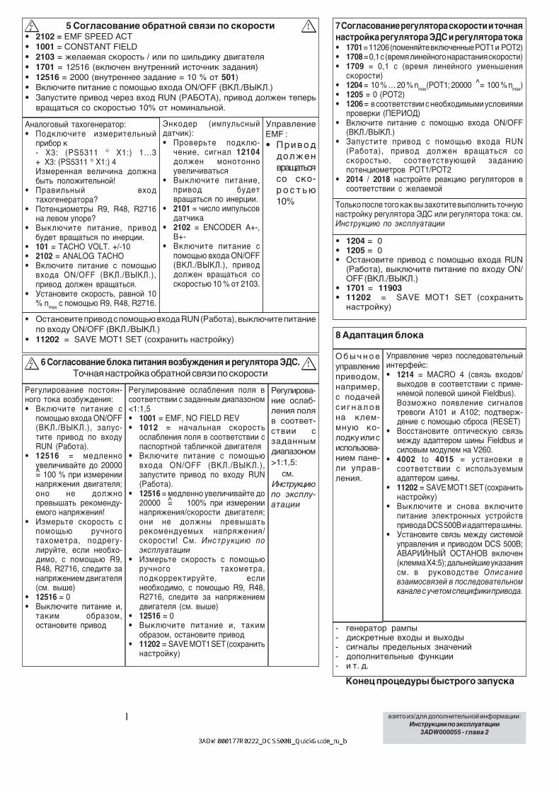
I взято из/для дополнительной информации:Инструкции по эксплуатации
3ADW000055 - глава 2
5 Согласование обратной связи по скорости• 2102 = EMF SPEED ACT• 1001 = CONSTANT FIELD• 2103 = желаемая скорость / или по шильдику двигателя• 1701 = 12516 (включен внутренний источник задания)• 12516 = 2000 (внутреннее задание = 10 % от 501)• Включите питание с помощью входа ON/OFF (ВКЛ./ВЫКЛ.)• Запустите привод через вход RUN (РАБОТА), привод должен теперь
вращаться со скоростью 10% от номинальной.
Аналоговый тахогенератор:• Подключите измерительный
прибор к- Х3: (PS5311 ® X1:) 1…3+ X3: (PS5311 ® X1:) 4Измеренная величина должнабыть положительной!
• Правильный входтахогенератора?
• Потенциометры R9, R48, R2716на левом упоре?
• Выключите питание, приводбудет вращаться по инерции.
• 101 = TACHO VOLT. +/-10• 2102 = ANALOG TACHO• Включите питание с помощью
входа ON/OFF (ВКЛ./ВЫКЛ.),привод должен вращаться.
• Установите скорость, равной 10% n
max с помощью R9, R48, R2716.
Энкодер (импульсныйдатчик):• Проверьте подклю-
чение, сигнал 12104должен монотонноувеличиваться
• Выключите питание,привод будетвращаться по инерции.
• 2101 = число импульсовдатчика
• 2102 = ENCODER A+-,B+-
• Включите питание спомощью входа ON/OFF(ВКЛ./ВЫКЛ.), приводдолжен вращаться соскоростью 10 % от 2103.
УправлениеEMF :• Привод
долженвращатьсясо ско-р о с т ь ю10%
• Остановите привод с помощью входа RUN (Работа), выключите питаниепо входу ON/OFF (ВКЛ./ВЫКЛ.)
• 11202 = SAVE MOT1 SET (сохранить настройку)
7 Согласование регулятора скорости и точнаянастройка регулятора ЭДС и регулятора тока• 1701 = 11206 (поменяйте включенные POT1 и POT2)• 1708 = 0,1 с (время линейного нарастания скорости)• 1709 = 0,1 с (время линейного уменьшения
скорости)• 1204 = 10 % … 20 % n
max(POT1; 20000 = 100 % n
max)
• 1205 = 0 (POT2)• 1206 = в соответствии с необходимыми условиями
проверки (ПЕРИОД)• Включите питание с помощью входа ON/OFF
(ВКЛ./ВЫКЛ.)• Запустите привод с помощью входа RUN
(Работа), привод должен вращаться соскоростью, соответствующей заданиюпотенциометров POT1/POT2
• 2014 / 2018 настройте реакцию регуляторов всоответствии с желаемой
Только после того как вы захотите выполнить точнуюнастройку регулятора ЭДС или регулятора тока: см.Инструкцию по эксплуатации
• 1204 = 0• 1205 = 0• Остановите привод с помощью входа RUN
(Работа), выключите питание по входу ON/OFF (ВКЛ./ВЫКЛ.)
• 1701 = 11903• 11202 = SAVE MOT1 SET (сохранить
настройку)
8 Адаптация блока
6 Согласование блока питания возбуждения и регулятора ЭДС.Точная настройка обратной связи по скорости
Регулирование постоян-ного тока возбуждения:• Включите питание с
помощью входа ON/OFF(ВКЛ./ВЫКЛ.), запус-тите привод по входуRUN (Работа).
• 12516 = медленноувеличивайте до 20000= 100 % при измерениинапряжения двигателя;оно не должнопревышать рекоменду-емого напряжения!
• Измерьте скорость спомощью ручноготахометра, подрегу-лируйте, если необхо-димо, с помощью R9,R48, R2716, следите занапряжением двигателя(см. выше)
• 12516 = 0• Выключите питание и,
таким образом,остановите привод
Регулирование ослабления поля всоответствии с заданным диапазоном<1:1,5• 1001 = EMF, NO FIELD REV• 1012 = начальная скорость
ослабления поля в соответствии спаспортной табличкой двигателя
• Включите питание с помощьювхода ON/OFF (ВКЛ./ВЫКЛ.),запустите привод по входу RUN(Работа).
• 12516 = медленно увеличивайте до20000 = 100% при измерениинапряжения/скорости двигателя;они не должны превышатьрекомендуемых напряжения/скорости! См. Инструкцию поэксплуатации
• Измерьте скорость с помощьюручного тахометра,подкорректируйте, еслинеобходимо, с помощью R9, R48,R2716, следите за напряжениемдвигателя (см. выше)
• 12516 = 0• Выключите питание и, таким
образом, остановите привод• 11202 = SAVE MOT1 SET (сохранить
настройку)
Регулирова-ние ослаб-ления поляв соответ-ствии сзаданнымдиапазоном>1:1,5:
см. Инструкциюпо эксплу-атации
О б ы ч н о еуправлениеприводом,например,с подачейс и г н а л о вна клем-мную ко-лодку или сиспользова-нием пане-ли управ-ления.
Управление через последовательныйинтерфейс:• 1214 = MACRO 4 (связь входов/
выходов в соответствии с приме-няемой полевой шиной Fieldbus).Возможно появление сигналовтревоги A101 и A102; подтверж-дение с помощью сброса (RESET)
• Восстановите оптическую связьмежду адаптером шины Fieldbus исиловым модулем на V260.
• 4002 to 4015 = установки всоответствии с используемымадаптером шины.
• 11202 = SAVE MOT1 SET (сохранитьнастройку)
• Выключите и снова включитепитание электронных устройствпривода DCS 500B и адаптера шины.
• Установите связь между системойуправления и приводом DCS 500B;АВАРИЙНЫЙ ОСТАНОВ включен(клемма Х4:5); дальнейшие указаниясм. в руководстве Описаниевзаимосвязей в последовательномканале с учетом специфики привода.
- генератор рампы- дискретные входы и выходы- сигналы предельных значений- дополнительные функции- и т. д.
Конец процедуры быстрого запуска
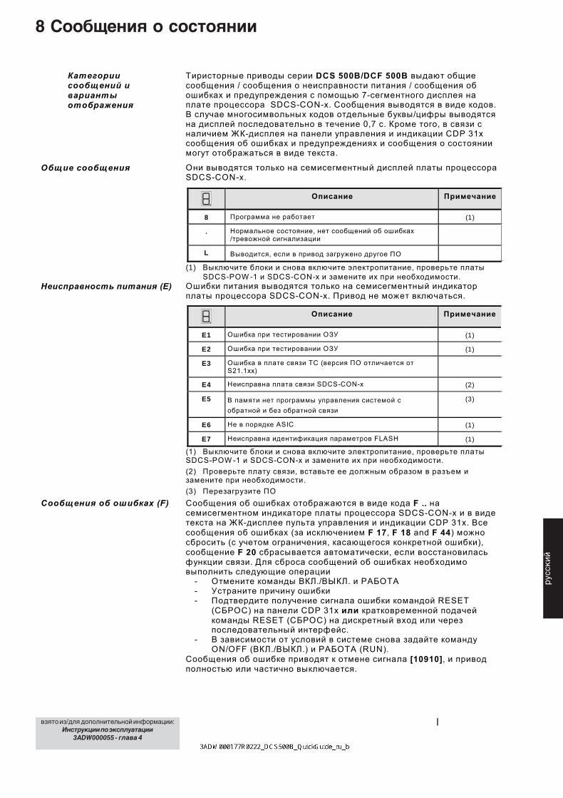
I
рус
ски
й
8 Сообщения о состоянии
Категории сообщений и варианты отображения
Тиристорные приводы серии DCS 500B/DCF 500B выдают общие сообщения / сообщения о неисправности питания / сообщения об ошибках и предупреждения с помощью 7-сегментного дисплея на плате процессора SDCS-CON-x. Сообщения выводятся в виде кодов. В случае многосимвольных кодов отдельные буквы /цифры выводятся на дисплей последовательно в течение 0,7 с. Кроме того, в связи с наличием ЖК-дисплея на панели управления и индикации CDP 31x сообщения об ошибках и предупреждениях и сообщения о состоянии могут отображаться в виде текста.
Общие сообщения
Они выводятся только на семисегментный дисплей платы процессора SDCS-CON-x.
Описание Примечание
8 Программа не работает (1)
. Нормальное состояние, нет сообщений об ошибках /тревожной сигнализации
L Выводится, если в привод загружено другое ПО
(1) Выключите блоки и снова включите электропитание, проверьте платы SDCS-POW -1 и SDCS-CON-x и замените их при необходимости.
Неисправность питания (E) Ошибки питания выводятся только на семисегментный индикатор платы процессора SDCS-CON-x. Привод не может включаться.
Описание Примечание
E1 Ошибка при тестировании ОЗУ (1)
E2 Ошибка при тестировании ОЗУ (1)
E3 Ошибка в плате связи ТС (версия ПО отличается от S21.1xx)
E4 Неисправна плата связи SDCS-CON-x (2)
E5 В памяти нет программы управления системой с обратной и без обратной связи
(3)
E6 Не в порядке ASIC (1)
E7 Неисправна идентификация параметров FLASH (1)
(1) Выключите блоки и снова включите электропитание, проверьте платы SDCS-POW -1 и SDCS-CON-x и замените их при необходимости. (2) Проверьте плату связи, вставьте ее должным образом в разъем и замените при необходимости. (3) Перезагрузите ПО
Сообщения об ошибках (F)
Сообщения об ошибках отображаются в виде кода F .. на семисегментном индикаторе платы процессора SDCS-CON-x и в виде текста на ЖК-дисплее пульта управления и индикации CDP 31x. Все сообщения об ошибках (за исключением F 17, F 18 and F 44) можно сбросить (с учетом ограничения, касающегося конкретной ошибки), сообщение F 20 сбрасывается автоматически, если восстановилась функции связи. Для сброса сообщений об ошибках необходимо выполнить следующие операции
- Отмените команды ВКЛ./ВЫКЛ. и РАБОТА - Устраните причину ошибки - Подтвердите получение сигнала ошибки командой RESET
(СБРОС) на панели CDP 31x или кратковременной подачей команды RESET (СБРОС) на дискретный вход или через последовательный интерфейс.
- В зависимости от условий в системе снова задайте команду ON/OFF (ВКЛ./ВЫКЛ.) и РАБОТА (RUN).
Сообщения об ошибке приводят к отмене сигнала [10910], и привод полностью или частично выключается.
взято из/для дополнительной информации:Инструкции по эксплуатации
3ADW000055 - глава 4
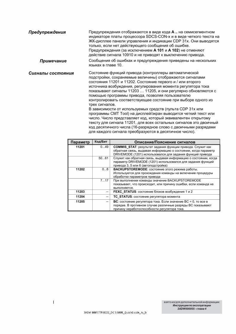
I
Предупреждения Предупреждения отображаются в виде кода А .. на семисегментном индикаторе платы процессора SDCS-CON-x и в виде четкого текста на ЖК-дисплее панели управления и индикации CDP 31x. Они выводятся только, если нет действующего сообщения об ошибке. Предупреждения (за исключением A 101 и A 102) не отменяют действие сигнала 10910 и не приводят к выключению привода.
Примечание Сообщения об ошибках и предупреждения приведены на нескольких языках в главе 10.
Сигналы состояния
Состояние функций привода (контроллеры автоматической подстройки, сохраняемые величины) отображаются сигналами состояния 11201 и 11202. Состояние первого и / или второго источника возбуждения, регулирования момента регулятора тока показывают сигналы 11203 11205, и они регулярно обновляются с помощью программы привода, позволяя пользователю контролировать соответствующее состояние при выборе одного из трех сигналов. В зависимости от используемых средств (пульта CDP 31x или программы CMT Tool) на дисплей/экран выводится четкий текст или число. Число представляет код, который эквивалентен открытому тексту для сигнала 11201, для всех остальных сигналов это двоичный код десятичного числа (16-разрядное слово с двоичными разрядами для каждого сигнала преобразуются в десятичное число).
Параметр Код/Бит Описание/Пояснение сигналов
11201 0...49 COMMIS_STAT: результат задания функции привода. Служит как обратная связь, выдавая информацию о состоянии, когда параметр DRIVEMODE (1201) использовался для задания функций привода
50...61 Служит как обратная связь, выдавая информацию о состоянии, когда параметр DRIVEMODE (1201) использовался для задания функций привода 3, 5 или 6 (автоподстройка)
11202 0...6 BACKUPSTOREMODE: состояние этого режима работы. Используется для прохождения команды на включение процедуры обработки параметров привода
7...17 При выполнении команды значение BACKUPSTOREMODE показывает, что происходит, или причину ошибки, если команда не выполняется.
11203 -- FEXC_STATUS: состояние блоков возбуждения 1 и 2 11204 -- TC_STATUS: состояние регулятора момента 11205 -- BC: состояние регулятора тока. Если значение ВС = 0, то все в
порядке. В противном случае различные разряды ВС показывают причину неработоспособности регулятора тока.
взято из/для дополнительной информации:Инструкции по эксплуатации
3ADW000055 - глава 4
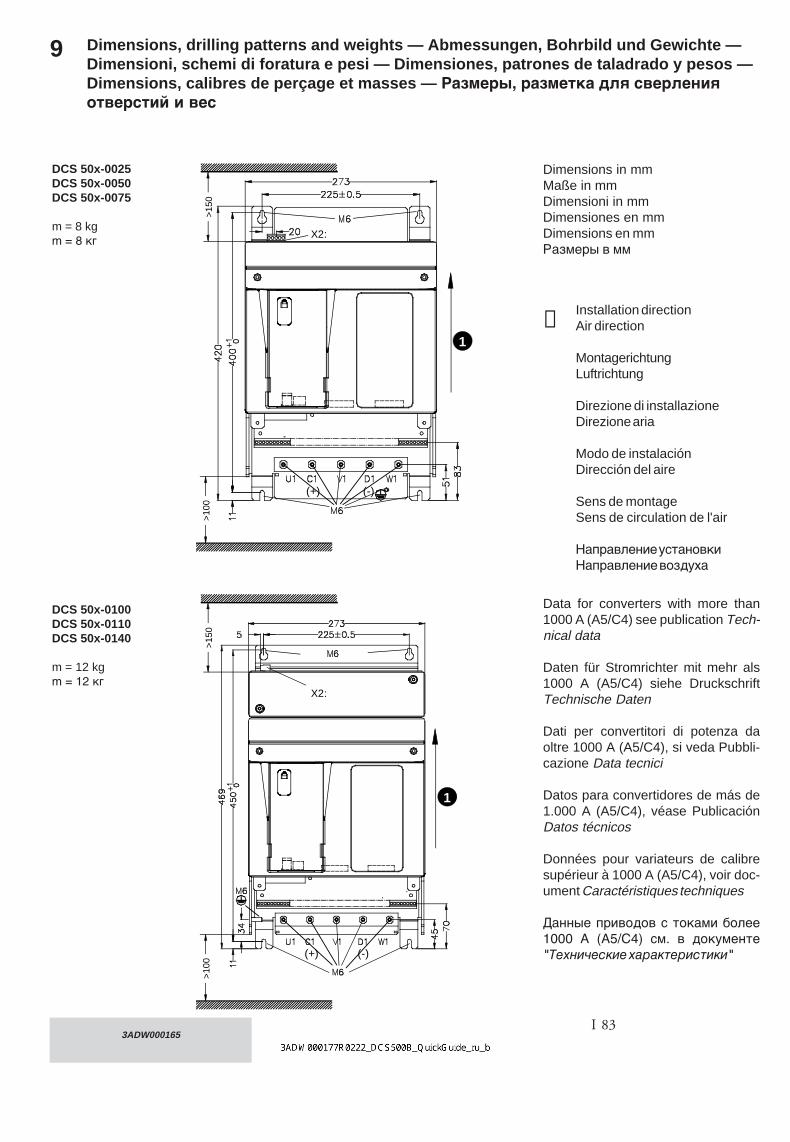
I 83
DCS 50x-0025DCS 50x-0050DCS 50x-0075
m = 8 kgm = 8 кг
DCS 50x-0100DCS 50x-0110DCS 50x-0140
m = 12 kgm = 12 кг
3ADW000165
Dimensions in mmMaße in mmDimensioni in mmDimensiones en mmDimensions en mmРазмеры в мм
Installation directionAir direction
MontagerichtungLuftrichtung
Direzione di installazioneDirezione aria
Modo de instalaciónDirección del aire
Sens de montageSens de circulation de l'air
Направление установкиНаправление воздуха
Data for converters with more than1000 A (A5/C4) see publication Tech-nical data
Daten für Stromrichter mit mehr als1000 A (A5/C4) siehe DruckschriftTechnische Daten
Dati per convertitori di potenza daoltre 1000 A (A5/C4), si veda Pubbli-cazione Data tecnici
Datos para convertidores de más de1.000 A (A5/C4), véase PublicaciónDatos técnicos
Données pour variateurs de calibresupérieur à 1000 A (A5/C4), voir doc-ument Caractéristiques techniques
Данные приводов с токами более1000 А (А5/С4) см. в документе"Технические характеристики"
>15
0
(+) (-)
>10
0
1
X2:
(+) (-)
X2:
>15
0 >
100
1
Dimensions, drilling patterns and weights — Abmessungen, Bohrbild und Gewichte —Dimensioni, schemi di foratura e pesi — Dimensiones, patrones de taladrado y pesos —Dimensions, calibres de perçage et masses — Размеры, разметка для сверленияотверстий и вес
9
➊
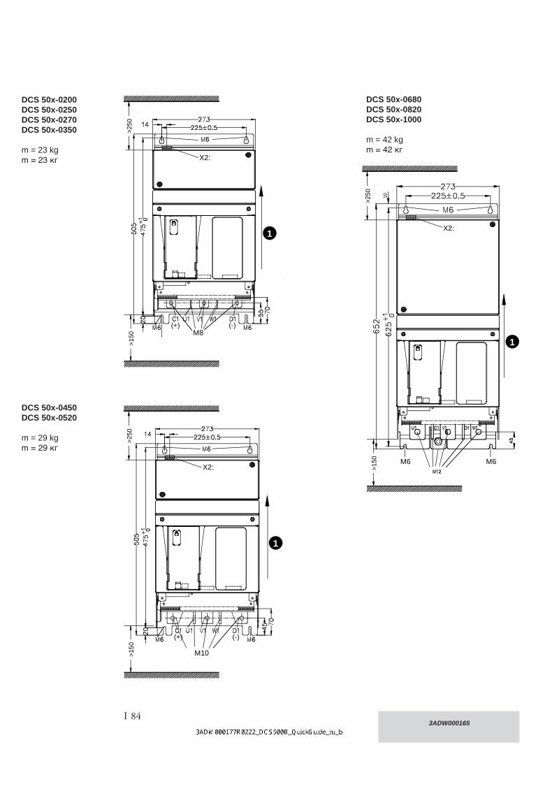
I 84
DCS 50x-0680DCS 50x-0820DCS 50x-1000
m = 42 kgm = 42 кг
DCS 50x-0200DCS 50x-0250DCS 50x-0270DCS 50x-0350
m = 23 kgm = 23 кг
DCS 50x-0450DCS 50x-0520
m = 29 kgm = 29 кг
3ADW000165
(+) (-)M8
X2:
>25
0 >
150
1
(+) (-)
>25
0 >
150
M10
1
X2:
10
>25
0 >
150 M6M6
1
X2:
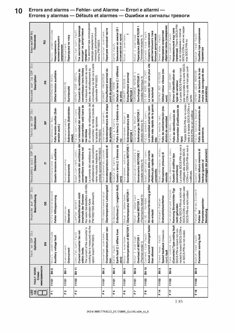
I 85
Errors and alarms — Fehler- und Alarme — Errori e allarmi —Errores y alarmas — Défauts et alarmes — Ошибки и сигналы тревоги
10
LE
D
СД
F
AU
LT
_WO
RD
Сл
ов
о
неи
спр
авн
ост
и
Text on CDP 31x
Def
init
ion
EN
Anzeige auf CDP 31x
Bes
chre
ibu
ng
DE
Messaggio sull CDP 31x
Des
criz
ion
e
IT
Texto en CDP 31x
Def
inic
ión
SP
Message sur la CDP 31x
Des
crip
tio
n
FR
CD
P 3
1x
По
ясн
ени
е
RU
F 1
11
101
Bit
0
Auxil. undervoltage
Au
xilia
ry v
olt
age
fau
lt
Hilfs-Unterspannung
Feh
ler
Hilf
ssp
ann
un
g
Sottotensione aux.
Gu
asto
ten
sio
ne
ausi
liari
a Bajatension Aux.
Fal
lo t
ensi
ón
au
xilia
r (S
ub
-te
nsi
ón
au
xil.)
SOUSTENSION AUXIL
Déf
aut
ten
sio
n a
uxi
liair
e
Auxil. undervoltage
Неи
спр
авн
ост
ь
всп
ом
ога
тел
ьн
ого
н
апр
яж
ени
я
F 2
11
101
Bit
1
Overcurrent
Ove
rcu
rren
tUeberstrom
Üb
erst
rom
Sovraccorrente
So
vrac
orr
ente
Sobrecorriente
So
bre
corr
ien
te (
So
bre
inte
n-
sid
ad)
SURINTENSITE
Su
rin
ten
sité
Overcurrent
Пер
егр
узк
а п
о т
ок
у
F 3
11
103
Bit
11
Conv.fan curr.fault
Cu
rren
t co
nve
rter
fan
no
t w
ith
in li
mit
s T
he c
urre
nt o
f the
con
vert
er´s
co
olin
g fa
n is
mea
sure
d vi
a th
e op
tion
boar
d P
W10
02/3
.
Luefter defekt
Ger
ätel
üft
erst
rom
nic
ht
inn
erh
alb
der
Gre
nze
n
Nur
wen
n G
erät
elüf
ters
mit
Hilf
e de
r op
tiona
len
Kar
te
PW
1002
/100
3 üb
erw
acht
.
Guast.cor.vent.conv.
La
corr
ente
del
ven
tila
tore
del
co
nve
rtit
ore
no
n r
ien
tra
nei
lim
iti
La c
orre
nte
del v
entil
ator
e di
ra
ffred
dam
ento
del
con
vert
itore
vi
ene
mis
urat
a m
edia
nte
la
sche
da o
pzio
nale
PW
1002
/3.
Fallo corr.vent.conv
La
inte
nsi
dad
del
ven
tila
do
r d
el c
on
vert
ido
r es
tá f
uer
a d
e lo
s lím
ites
El v
entil
ador
de
refr
i ger
ació
n de
l co
nver
tidor
se
mid
e a
trav
és d
e la
tarje
ta d
e op
cion
es
PW
1002
/3.
DEFAUT COUR VENTIL
Co
ura
nt
du
ven
tila
teu
r d
u
con
vert
isse
ur
ho
rs li
mit
esLa
mes
ure
du c
oura
nt d
u ve
nti-
late
ur d
e re
froi
diss
emen
t du
conv
ertis
seur
se
fait
via
la c
arte
op
tionn
elle
PW
1002
/3.
Conv.fan curr.fault
То
к в
енти
ля
тор
а п
ри
во
да
вы
ход
ит
за д
оп
усти
мы
е п
ред
елы
Т
ок в
енти
лят
ора
охл
ажд
ения
пр
ивод
а из
мер
яетс
я с
пом
ощью
доп
олни
тел
ьной
пл
аты
PW
1002
/3.
F 4
11
101
Bit
3
Converter overtemp.
Ove
rtem
per
atu
re p
ow
er s
ec-
tio
n
STR-Uebertemperatur
Üb
erte
mp
erat
ur
Lei
stu
ng
stei
lSovratemperat.conver
So
vrat
emp
erat
ura
sez
ion
e d
i p
ote
nza
Sobretemp. Convert.
So
bre
tem
per
atu
ra d
e la
eta
pa
de
po
ten
cia
ECHAUFT VARIATEUR
Ech
auff
emen
t an
orm
al d
u
po
nt
de
pu
issa
nce
Converter overtemp.
Пер
егр
ев с
ил
ов
ой
час
ти
F 5
11
101
Bit
4
Earth fault
Ear
th f
ault
( I
dif
fers
fro
m
zero
)
Erdschluss
Erd
sch
luss
( I
un
gle
ich
Nu
ll) Guasto di terra
Gu
asto
a t
erra
( I
div
erso
da
zero
)
Fallo a tierra
Fal
lo a
tie
rra
( I
dis
tin
to a
ce-
ro)
DEFAUT TERRE
Déf
aut
de
terr
e (
I d
iffé
ren
t d
e zé
ro)
Earth fault
Зам
ык
ани
е н
а зе
мл
ю (
S I
отл
ича
ется
от
нул
я)
F 6
11
101
Bit
5
Motor 1 overtemp.
Ove
rtem
per
atu
re o
f M
OT
OR
1Motor 1 Uebertemp.
Üb
erte
mp
erat
ur
MO
TO
R 1
Sovratemp. motore 1
So
vrat
emp
erat
ura
MO
TO
RE
1Sobretemp. Motor 1
So
bre
tem
per
atu
ra d
el
MO
TO
R 1
ECHAUFT MOTEUR 1
Ech
auff
emen
t an
orm
al
MO
TE
UR
1
Motor 1 overtemp.
1
F 7
11
101
Bit
6
Motor 1 overload
Ove
rlo
ad o
f M
OT
OR
1
(The
rmal
mod
el 1
)
Motor 1 Ueberlast
Üb
erla
stM
OT
OR
1
(The
rmis
ches
Mod
ell 1
)
sovraccaric.motore 1
So
vrac
cari
co M
OT
OR
E 1
(m
odel
lo te
rmic
o 1)
Sobrecarga Motor 1
So
bre
carg
a d
el M
OT
OR
1
(Mod
elo
térm
ico
1)
SURCHARGE MOTEUR 1
Su
rch
arg
e M
OT
EU
R 1
(mod
èle
ther
miq
ue 1
)
Motor 1 overload
Пер
егр
узк
а Д
ВИ
ГА
ТЕ
ЛЯ
1
(Теп
лов
ая м
одел
ь 1)
F 8
11
103
Bit
10
Current rise fault
Act
ual
cu
rren
t ch
ang
ed f
aste
r th
an a
llow
ed
di/dt > Vorgabe
Str
om
istw
ertä
nd
eru
ng
grö
ßer
al
s er
lau
bt
Guast.derivata corr.
Var
iazi
on
e d
ella
co
rren
te
effe
ttiv
a p
iù r
apid
a d
el
con
sen
tito
Fallo aumento corr.
La
inte
nsi
dad
act
ual
ha
cam
-b
iad
o m
ás r
ápid
o d
e lo
per
mi-
tid
o
DI/DT HORS DE LIMIT
Le
cou
ran
t ré
el v
arie
plu
s vi
te
qu
’au
tori
sé
Current rise fault
Ск
ор
ост
ь и
змен
ени
я
дей
ств
ите
ль
но
го т
ок
а б
ол
ьш
е д
оп
усти
мо
й
F 1
4 11
102
Bit
5
Speed meas. fault
Sp
eed
fee
db
ack
(mea
sure
-m
ent)
fau
lt
Drehzahl-Fehler
Dre
hza
hlis
twer
tfeh
ler
Guas.retroazio veloc.
Ret
roaz
ion
e (m
isu
ra)
di
velo
cità
Fallo medida vel.
Fal
lo d
e re
alim
enta
ció
n (
me-
dic
ión
) d
e ve
loci
dad
DEFAUT RET VITESSE
Déf
aut
reto
ur
vite
sse
(me-
sure
)
Speed meas. fault
Неи
спр
авн
а ск
ор
ост
ная
о
бр
атн
ая с
вя
зь (и
змер
ени
е)
F 1
7 11
102
Bit
8
Type coding fault
(Co
nve
rter
) T
ype
cod
ing
fau
lt
SD
CS
-PIN
-xx
boar
d no
t con
-ne
cted
to b
oard
SD
CS
-CO
N-x
or
SD
CS
-PIN
-xx
not c
oded
.
Typ-Kodierung falsch
Ken
nu
ng
Str
om
rich
ter-
Typ
n
ich
t g
efu
nd
enK
arte
SD
CS
-PIN
-xx
nich
t mit
SD
CS
-CO
N-x
ver
bund
en o
der
SD
CS
-PIN
-xx
nich
t cod
iert
.
Guas.identifica conv.
Gu
asto
di c
od
ific
a ti
po
(c
on
vert
ito
re)
La s
ched
a S
DC
S-P
IN-x
x no
n è
colle
gata
alla
sch
eda
SD
CS
-C
ON
-x o
l’S
DC
S-P
IN-x
x no
n è
codi
ficat
a.
Fallo ident. conv.
Fal
lo d
e id
enti
fica
ció
n d
e C
on
vert
ido
r (C
od
ific
ació
n d
e ti
po
)
Tar
jeta
SD
CS
-PIN
-xx
no c
onec
-ta
da a
la ta
rjeta
SD
CS
-CO
N-x
o
SD
CS
-PIN
-xx
sin
codi
ficar
.
DEFAUT IDENT CONV
Err
eur
d’id
enti
fica
tio
n d
u
typ
e d
e va
riat
eur
La c
arte
SD
CS
-PIN
-xx
n'es
t pa
s ra
ccor
dée
à la
car
te S
DC
S-
CO
N-x
ou
elle
n'e
st p
as c
onfi-
guré
e.
Type coding fault
Неп
рав
ил
ьн
ый
ко
д т
ип
а (п
ри
во
да)
. Пл
ата
SD
CS
-PIN
-xx
не
соед
инен
а с
плат
ой
SD
CS
-CO
N-x
, ил
и не
зад
ан
код
SD
CS
-PIN
-xx
F 1
8 11
102
Bit
9
Backup read fault
Par
amet
er s
avin
g f
ault
Fehler Param.Sicherg
Feh
ler
bei
P
aram
eter
spei
cher
-B
enu
tzu
ng
Guasto memoria
Gu
asto
lett
ura
mem
ori
a d
i b
acku
p (
gu
asto
al
salv
atag
gio
dei
par
amet
ri)
Fallo lectura Backup
Fal
lo d
e al
mac
enam
ien
to d
e p
arám
etro
s
DEFAUT LECT MEMOIRE
Err
eur
de
lect
ure
de
la m
é-m
oir
e (d
e sa
uve
gar
de
des
p
aram
ètre
s)
Backup read fault
Ош
иб
ка
пр
и с
охр
анен
ии
п
арам
етр
а
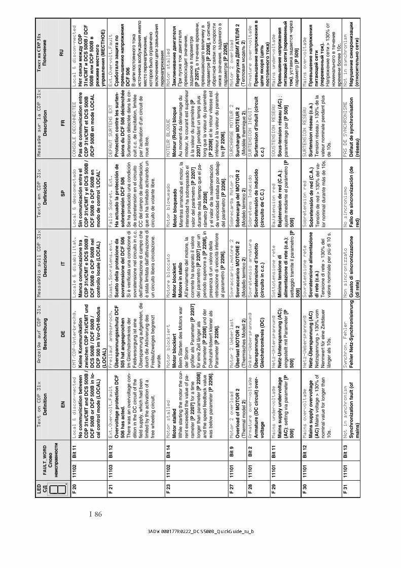
I 86
LE
D
СД
F
AU
LT
_WO
RD
Сл
ов
о
неи
спр
авн
ост
и
Text on CDP 31x
Def
init
ion
EN
Anzeige auf CDP 31x
Bes
chre
ibu
ng
DE
Messaggio sull CDP 31x
Des
criz
ion
e
IT
Texto en CDP 31x
Def
inic
ión
SP
Message sur la CDP 31x
Des
crip
tio
n
FR
CD
P 3
1x
По
ясн
ени
е
RU
F 2
0 11
102
Bit
11
Local & discon-nected
No
co
mm
un
icat
ion
bet
wee
n
CD
P 3
1x/C
MT
an
d D
CS
500
B /
DC
F 5
00B
or
DC
P 5
00B
in lo
-ca
l co
ntr
ol m
od
e (L
OC
AL
)
CMT/CDP-Unterbrechg.
Kei
ne
Ko
mm
un
ikat
ion
zw
isch
en C
DP
31x
/CM
T u
nd
D
CS
500
B /
DC
F 5
00B
/ D
CP
500
im V
or-
Ort
-Mo
du
s (L
OC
AL
)
Locale & disabilitat.
Man
ca c
om
un
icaz
ion
e tr
a C
DP
31x
/CM
T e
DC
S 5
00B
/ D
CF
500
B o
DC
P 5
00B
nel
co
ntr
ollo
loca
le (
LO
CA
L)
Local & desconectado
Sin
co
mu
nic
ació
n e
ntr
e el
C
DP
31x
/CM
T y
el D
CS
500
B /
DC
F 5
00B
o D
CP
500
B e
n
mo
do
de
con
tro
l ‘L
OC
AL
’
CONSOLE DECONNECTEE
Pas
de
com
mu
nic
atio
n e
ntr
e C
DP
31x
/CM
T e
t D
CS
500
B
/DC
P 5
00B
en
mo
de
LO
CA
L
Local & discon-nected
Нет
св
язи
меж
ду
CD
P
31x/
CM
T и
DC
S 5
00B
/ D
CF
50
0B и
ли
DC
P 5
00B
в
реж
им
е м
естн
ого
уп
рав
лен
ия
(М
ЕС
ТН
ОЕ
)
F 2
1 11
103
Bit
12
Ext.Overvolt.Fault
Ove
rvo
ltag
e p
rote
ctio
n D
CF
50
6 h
as a
cted
. T
here
was
an
over
volta
ge c
on-
ditio
n in
the
DC
circ
uit o
f the
fie
ld s
uppl
y, w
hich
had
bee
n lim
ited
by th
e ac
tivat
ion
of a
fr
ee w
heel
ing
circ
uit.
Freilauf angesproch.
Üb
ersp
ann
un
gss
chu
tz D
CF
50
5 h
at a
ng
esp
roch
en
Im G
leic
hstr
omkr
eis
der
Fel
dver
sorg
ung
ist e
ine
Übe
rspa
nnun
g au
fget
rete
n, d
ie
durc
h di
e A
ktiv
ieru
ng d
es
Fre
ilauf
zwei
ges
begr
enzt
w
urde
.
Guast.Sovratens.ext.
Sca
tto
del
la p
rote
zio
ne
da
sovr
aten
sio
ne
del
DC
F 5
06
Si è
ver
ifica
ta u
na c
ondi
zion
e di
so
vrat
ensi
one
nel c
ircui
to in
c.c
. de
ll'al
imen
tazi
one
di c
ampo
che
è
stat
a lim
itata
dal
l'atti
vazi
one
di
un c
ircui
to li
bera
circ
olaz
ione
.
Fallo Sobret. Ext.
Ha
actu
ado
la p
rote
cció
n d
e so
bre
ten
sió
n D
CF
506
Se
ha p
rodu
cido
una
con
dici
ón
de s
obre
tens
ión
en e
l circ
uito
C
C d
el c
ampo
de
alim
enta
ción
, qu
e se
ha
limita
do a
ctiv
ando
un
circ
uito
de
vola
nte
libre
.
DEFAUT SURTENS EXT
Pro
tect
ion
co
ntr
e le
s su
rten
-si
on
s d
u D
CF
506
déc
len
chée
Sur
tens
ion
déte
ctée
dan
s le
cir-
cuit
c.c.
de
l’exc
itatio
n, li
mité
e pa
r l’a
ctiv
atio
n d’
un c
ircui
t de
roue
libr
e.
Ext.Overvolt.Fault
Ср
або
тал
а за
щи
та п
о
пр
евы
шен
ию
нап
ря
жен
ия
D
CF
506
В
цеп
и по
стоя
нног
о то
ка
исто
чник
а во
збуж
ден
ия и
мел
о м
есто
пер
енап
ряж
ение
, ко
торо
е бы
ло о
гран
ичен
о вк
люче
нием
цеп
и за
мы
кани
я пе
рена
пряж
ения
F
23
1110
2B
it 1
4 Motor stalled
Mo
tor
stal
led
W
hile
sta
rtin
g th
e m
otor
the
cur-
rent
exc
eede
d th
e va
lue
of p
a-ra
met
er [
P 2
207]
for
a tim
e lo
nger
than
par
amet
er [
P 2
208]
and
the
spee
d fe
edba
ck v
alue
w
as b
elow
par
amet
er [
P 2
206]
.
Motor blockiert
Mo
tor
blo
ckie
rt
Bei
m S
tart
en d
es M
otor
s w
ar
der
Str
om
größ
er a
ls P
aram
eter
[P
220
7]fü
r ei
ne Z
eit l
änge
r al
s P
aram
eter
[P
220
8] u
nd d
er
Dre
hzah
l-Ist
wer
t kle
iner
als
P
aram
eter
[P
220
6].
Motore bloccato
Mo
tor
blo
ckie
rt
Mo
tore
in s
tallo
A
ll’av
viam
ento
del
mot
ore,
la
corr
ente
ha
supe
rato
il v
alor
e de
l par
amet
ro [
P 2
207]
per
un
perio
do s
uper
iore
a [
P 2
208]
, in
pres
enza
di u
n va
lore
del
la
retr
oazi
one
di v
eloc
ità in
ferio
re
al p
aram
etro
[P
220
6].
Motor bloqueado
Mo
tor
blo
qu
ead
o
Mie
ntra
s ar
ranc
aba
el m
otor
,la
inte
nsid
ad h
a so
brep
asad
o el
va
lor
del p
arám
etro
[P
220
7]du
rant
e m
ás ti
empo
que
el p
a-rá
met
ro [
P 2
208]
y
el v
alor
de
la r
ealim
enta
ción
de
vel
ocid
ad e
stab
a po
r de
bajo
de
l par
ámet
ro [
P 2
206]
.
MOTEUR BLOQUE
Mo
teu
r (R
oto
r) b
loq
ué
Au
mom
ent d
u dé
mar
rage
du
mot
eur,
le c
oura
nt e
st s
upér
ieur
à
la v
aleu
r du
par
amèt
re [
P22
07]
pend
ant u
n te
mps
plu
s lo
ng q
ue la
val
eur
du p
aram
ètre
[P
220
8] e
t le
reto
ur v
itess
e es
t in
férie
ur à
la v
aleu
r du
par
amè-
tre
[P 2
206]
.
Motor stalled
Зак
ли
ни
ван
ие
дв
ига
тел
я
При
пус
ке т
ок д
вига
тел
я пр
евос
ход
ит з
наче
ние,
за
дан
ное
в па
рам
етре
[P
220
7], в
теч
ение
вре
мен
и,
прев
ыш
ающ
его
вел
ичин
у в
пара
мет
ре [
P 2
208]
, а с
игна
л
обра
тной
свя
зи п
о ск
орос
ти
ниж
е зн
ачен
ия, з
адан
ного
в
пара
мет
ре [
P 2
206]
. F
27
1110
1B
it 9
Motor 2 overload
Ove
rlo
ad o
f M
OT
OR
2
(The
rmal
mod
el 2
)
Motor 2 Ueberlast
Üb
erla
stM
OT
OR
2(T
herm
isch
es M
odel
l 2)
Sovraccaric.motore 2
So
vrac
cari
co M
OT
OR
E 2
(Mod
ello
term
ico
2)
Sobrecarga Motor 2
So
bre
carg
a d
el M
OT
OR
2(M
odel
o té
rmic
o 2)
SURCHARGE MOTEUR 2
Su
rch
arg
e M
OT
EU
R2
(M
odèl
e th
erm
ique
2).
Motor 2 overload
Пер
егр
узк
а Д
ВИ
ГА
ТЕ
ЛЯ
2
(Теп
лов
ая м
одел
ь 2)
F 2
8 11
101
Bit
2
Armature over-voltage
Arm
atu
re (
DC
cir
cuit
) o
ver-
volt
age
Anker-Ueberspannung
Üb
ersp
ann
un
g
Gle
ich
stro
mkr
eis
(DC
)
Sovratensio armatura
So
vrat
ensi
on
e d
’ind
ott
o
(cir
cuit
o in
c.c
.)
Sobretens Inducido
So
bre
ten
sió
n d
e in
du
cid
o
(cir
cuit
o d
e C
.C.)
SURTENSION INDUIT
Su
rten
sio
n d
'ind
uit
(ci
rcu
it
c.c.
)
Armature over-voltage
Пр
евы
шен
ие
нап
ря
жен
ия
в
цеп
и я
ко
ря
(ц
епь
п
ост
оя
нн
ого
то
ка)
F
29
1110
1B
it 1
1 Mains undervoltage
Mai
ns
sup
ply
un
der
volt
age
(AC
); s
ettin
g vi
a pa
ram
eter
[P
50
9]
Netz-Unterspannung
Net
z-U
nte
rsp
ann
un
g (
AC
);
eing
este
llt m
it P
aram
eter
[P
509]
Sottotensione rete
Min
ima
ten
sio
ne
di
alim
enta
zio
ne
di r
ete
(c.a
.);
setta
ggio
tram
ite il
par
amet
ro [
P50
9]
Bajatension red
Baj
aten
sio
n d
e re
d (
C.A
.);
ajus
te m
edia
nte
el p
arám
etro
[P
509]
SOUSTENSION RESEAU
So
us-
ten
sio
n r
ésea
u (
AC
) ;
para
mét
rage
par
[P
509
]
Mains undervoltage
Пр
евы
шен
ие
нап
ря
жен
ия
п
ита
ющ
ей с
ети
(пер
емен
ны
й
ток
), ус
тавк
а за
дае
тся
чере
з па
рам
етр
[P 5
09]
F 3
0 11
101
Bit
12
Mains overvoltage
Mai
ns
sup
ply
ove
rvo
ltag
e (A
C)
Mai
ns v
olta
ge >
130
% o
f no
min
al v
alue
for
long
er th
an
10s.
Netz-Ueberspannung
Net
z-Ü
ber
span
nu
ng
(A
C)
Net
zspa
nnun
g >
130%
vom
N
ennw
ert f
ür e
ine
Zei
tdau
er
läng
er a
ls 1
0s.
Sovratensione rete
So
vrat
ensi
on
e al
imen
tazi
on
e d
i ret
e(c
.a.)
Ten
sion
e di
ret
e >
130%
del
va
lore
nom
inal
e pe
r pi
ù di
10
s.
Sobretension red
So
bre
ten
sió
n d
e re
d (
C.A
.)T
ensi
ón d
e re
d >
130%
del
va-
lor
nom
inal
dur
ante
más
de
10s.
SURTENSION RESEAU
Su
rten
sio
n r
ésea
u (
c.a.
)T
ensi
on r
ésea
u >
130%
de
la
vale
ur n
omin
ale
pend
ant p
lus
de 1
0s.
Mains overvoltage
Пр
евы
шен
ие
нап
ря
жен
ия
п
ита
ющ
ей с
ети
(п
ерем
енн
ый
то
к).
Н
апря
жен
ие с
ети
> 1
30%
от
ном
инал
ьног
о в
тече
ние
врем
ени
бол
ее 1
0с.
F 3
1 11
101
Bit
13
Not in synchronism
Syn
chro
niz
atio
n f
ault
(o
f m
ain
s)
Synchron. Fehler
Feh
ler
Net
z-S
ynch
ron
isie
run
g Non sincronizzato
Gu
asto
di s
incr
on
izza
zio
ne
(di r
ete)
No sincronismo
Fal
lo d
e si
ncr
on
izac
ión
(d
e re
d)
PAS DE SYNCHRONISME
Déf
aut
de
syn
chro
nis
atio
n
(rés
eau
)
Not in synchronism
Нар
ушен
ие
син
хро
ни
зац
ии
(о
тно
сите
льн
о с
ети
)
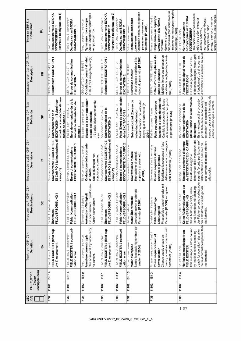
I 87
LE
D
СД
F
AU
LT
_WO
RD
Сл
ов
о
неи
спр
авн
ост
и
Text on CDP 31x
Def
init
ion
EN
Anzeige auf CDP 31x
Bes
chre
ibu
ng
DE
Messaggio sull CDP 31x
Des
criz
ion
e
IT
Texto en CDP 31x
Def
inic
ión
SP
Message sur la CDP 31x
Des
crip
tio
n
FR
CD
P 3
1x
По
ясн
ени
е
RU
F 3
2 11
101
Bit
14
Field ex.1 overcurr
FIE
LD
EX
CIT
ER
1 (
fiel
d s
up
-p
ly 1
) o
verc
urr
ent
Feld 1 Ueberstrom
Üb
erst
rom
FE
LD
VE
RS
OR
GU
NG
1
Sovracorrente eccit1
So
vrac
orr
ente
EC
CIT
AT
RIC
E
DI C
AM
PO
1 (a
limen
tazi
on
e d
i ca
mp
o 1
)
Sobrecorr. excit. 1
So
bre
corr
ien
te d
e la
E
XC
ITA
CIÓ
N 1
(S
ob
rein
ten
-si
dad
de
la u
nid
ad d
e al
imen
-ta
ció
n d
e ca
mp
o 1
)
SURINTENSITE EXCIT 1
Su
rin
ten
sité
EX
CIT
AT
ION
1Field ex.1 overcurr
Пр
евы
шен
ие
ток
а Б
ЛО
КА
В
ОЗ
БУ
ЖД
ЕН
ИЯ
1
(ист
очн
ик
во
збуж
ден
ия
1)
F 3
3 11
101
Bit
15
Field ex.1 comerror
FIE
LD
EX
CIT
ER
1 c
om
mu
ni-
cati
on
err
or
Feld 1 Komm-Fehler
Feh
ler
Ko
mm
un
ikat
ion
FE
LD
VE
RS
OR
GU
NG
1
Error.comunica.ecc.1
Err
ore
di c
om
un
icaz
ion
e E
CC
ITA
TR
ICE
DI C
AM
PO
1
Fallo com. excit. 1
Err
or
de
com
un
icac
ión
de
la
un
idad
de
alim
enta
ció
n d
e ca
mp
o 1
DEFAUT COM EXCIT 1
Err
eur
de
com
mu
nic
atio
n
EX
CIT
AT
ION
1
Field ex.1 comerror
Ош
иб
ка
свя
зи Б
ЛО
КА
В
ОЗ
БУ
ЖД
ЕН
ИЯ
1
F 3
4 11
102
Bit
0
Arm. curent ripple
Arm
atu
re c
urr
ent
rip
ple
O
ne o
r se
vera
l thy
risto
rs c
arry
no
cur
rent
.
Strom-Welligkeit
An
kers
tro
m-W
ellig
keit
Ein
ode
r m
ehre
re T
hyris
tor(
en)
führ
en k
eine
n S
trom
Ripple corrent.armat
On
du
lazi
on
e d
ella
co
rren
te
d’in
do
tto
Uno
o p
iù ti
risto
ri no
n co
nduc
ono
corr
ente
.
Rizado corriente ind
Riz
ado
de
la c
orr
ien
te (
inte
n-
sid
ad)
del
ind
uci
do
1 ó
vario
s tir
isto
res
no c
ondu
-ce
n.
ONDULATION I INDUIT
On
du
lati
on
co
ura
nt
d'in
du
itD
éfau
t d'a
llum
age
thyr
isto
r(s)
.
Arm. curent ripple
Пул
ьса
ци
и т
ок
а я
ко
ря
О
дин
ил
и бо
лее
тир
исто
ров
не п
рово
дят
ток
F 3
5 11
102
Bit
1
Field ex.2 overcurr
FIE
LD
EX
CIT
ER
2 (
fiel
d s
up
-p
ly 2
) o
verc
urr
ent
Feld 2 Ueberstrom
Üb
erst
rom
FE
LD
VE
RS
OR
GU
NG
2
Sovracorrente eccit2
So
vrac
orr
ente
EC
CIT
AT
RIC
E
DI C
AM
PO
2 (
alim
enta
zio
ne
di
cam
po
2)
Sobrecorr excit. 2
So
bre
inte
nsi
dad
de
la
EX
CIT
AC
IÓN
2
SURINTENSITE EXCIT 2
Su
rin
ten
sité
EX
CIT
AT
ION
2Field ex.2 overcurr
Пр
евы
шен
ие
ток
а Б
ЛО
КА
В
ОЗ
БУ
ЖД
ЕН
ИЯ
2
(ист
очн
ик
во
збуж
ден
ия
2)
F 3
6 11
102
Bit
2
Field ex.2 comerror
FIE
LD
EX
CIT
ER
2 c
om
mu
ni-
cati
on
err
or
Feld 2 Komm-Fehler
Feh
ler
Ko
mm
un
ikat
ion
FE
LD
VE
RS
OR
GU
NG
2
Error.comunica.ecc.2
Err
ore
di c
om
un
icaz
ion
e E
CC
ITA
TR
ICE
DI C
AM
PO
2
Fallo com. excit. 2
Fal
lo (
Err
or)
de
com
un
icac
ión
d
e la
EX
CIT
AC
IÓN
2
DEFAUT COM EXCIT 2
Err
eur
de
com
mu
nic
atio
n
EX
CIT
AT
ION
2
Field ex.2 comerror
Ош
иб
ка
свя
зи Б
ЛО
КА
В
ОЗ
БУ
ЖД
ЕН
ИЯ
2
F 3
7 11
102
Bit
15
Motor overspeed
Mo
tor
ove
rsp
eed
S
peed
feed
back
hig
her
than
pa-
ram
eter
[P
220
4].
Ueberdrehzahl
Mo
tor-
Üb
erd
reh
zah
lD
rehz
ahl-I
stw
ert g
röß
er a
ls
Par
amet
er [
P 2
204]
.
Sovravelocita motore
So
vrav
elo
cità
mo
tore
Ret
roaz
ione
di v
eloc
ità
supe
riore
al p
aram
etro
[P
220
4].
Sobrevelocidad motor
So
bre
velo
cid
ad (
Exc
eso
de
velo
cid
ad)
del
mo
tor
Rea
limen
taci
ón d
e ve
loci
dad
may
or q
ue e
l par
ámet
ro [
P22
04].
SURVITESSE MOTEUR
Su
rvit
esse
mo
teu
rR
etou
r vi
tess
e su
périe
ur à
la
vale
ur d
u pa
ram
ètre
[P
220
4].
Motor overspeed
Пр
евы
шен
ие
ско
ро
сти
д
ви
гате
ля
О
брат
ная
связ
ь по
ско
рост
и пр
евы
шае
т зн
ачен
ие в
па
рам
етре
[P
220
4].
F 3
8 11
102
Bit
3
Phase sequence fault
Ph
ase
seq
uen
ce f
ault
of
po
wer
sec
tio
n
Cha
nge
supp
ly p
hase
se-
quen
cy o
r m
ake
corr
ectio
n w
ith
para
met
er [
P 5
06].
Drehfeld falsch
Feh
ler
Ph
asen
folg
e L
eist
un
gst
eil
Pha
senf
olge
taus
chen
ode
r m
it P
aram
eter
[P
506
] ko
rrig
iere
n.
Sequenza fasi errata
Gu
asto
seq
uen
za d
i fas
e se
zio
ne
di p
ote
nza
Mod
ifica
re la
seq
uenz
a di
fase
de
ll’al
imen
tazi
one
o co
rreg
gere
co
n il
para
met
ro [
P 5
06].
Fallo orden fases
Fal
lo s
ecu
enci
a (o
rden
) d
e fa
ses
de
la e
tap
a d
e p
ote
nci
aC
ambi
e la
sec
uenc
ia d
e fa
ses
de la
alim
enta
ción
o c
orrij
a co
n el
par
ámet
ro [
P 5
06].
DEFAUT ORDRE PHASES
Déf
aut
d'o
rdre
de
ph
ases
du
p
on
t d
e p
uis
san
ceM
odifi
ez l'
ordr
e de
s ph
ases
ou
mod
ifiez
le r
égla
ge d
u pa
ram
è-tr
e [P
506
].
Phase sequence fault
Неп
рав
ил
ьн
ый
по
ря
до
к
след
ов
ани
я ф
аз б
ло
ка
пи
тан
ия
И
змен
ите
поря
док
сл
едов
ания
фаз
нап
ряж
ений
пи
тани
я ил
и от
корр
екти
руйт
е па
рам
етр
[P 5
06].
F
39
1110
2B
it 4
No field ack.
No
fie
ld a
ckn
ow
led
ge
fro
m
FIE
LD
EX
CIT
ER
T
his
mes
sage
is e
ither
cau
sed
by th
e fie
ld e
xcite
r´s
mis
sing
„r
eady
for
oper
atio
n“ s
igna
l or
the
field
cur
rent
bei
n g lo
wer
than
the
thre
shol
d.
Summenfehler Feld
Kei
ne
Rü
ckm
eld
un
g v
on
der
F
EL
DV
ER
SO
RG
UN
GD
iese
Mel
dung
erf
olgt
, wen
n ke
ine
Bet
riebs
bere
it-M
eldu
ng
der
Fel
dver
sor g
ung
vorli
egt o
der
der
Fel
dstr
om is
t nie
drig
er a
ls
die
Sch
wel
le.
Campo non presente
Nes
sun
a co
nfe
rma
di c
amp
o
dal
l’EC
CIT
AT
RIC
E D
I CA
MP
OQ
uest
o m
essa
ggio
è
dete
rmin
ato
dalla
man
canz
a de
l se
gnal
e "p
ront
o pe
r fu
nzio
nare
" de
ll'ec
citta
tric
e di
cam
po o
da
una
corr
ente
di c
ampo
infe
riore
al
la s
oglia
.
No campo reconocido
Sin
rec
on
oci
mie
nto
de
la
EX
CIT
AC
IÓN
(d
e la
un
idad
de
alim
enta
ció
n
de
cam
po
)E
ste
men
saje
est
á pr
ovoc
ado
por
la fa
lta d
e la
señ
al „
read
y fo
r op
erat
ion“
de
exci
taci
ón d
el
cam
po o
por
ser
la in
tens
idad
de
cam
po in
ferio
r qu
e el
um
bral
.
ABS ACQUIT EXCITAT
Ab
sen
ce d
e si
gn
al r
eto
ur
de
l'EX
CIT
AT
ION
Ce
mes
sage
app
araî
t en
cas
d’ab
senc
e du
sig
nal r
etou
r „p
rêt
à fo
nctio
nner
“, o
u si
le c
oura
nt
d’ex
cita
tion
est i
nfér
ieur
au
seui
l.
No field ack.
Нет
по
дтв
ерж
ден
ия
в
озб
ужд
ени
я о
т Б
ЛО
КА
В
ОЗ
БУ
ЖД
ЕН
ИЯ
Э
то с
ообщ
ение
поя
вляе
тся
либ
о из
-за
сбоя
сиг
нал
а «г
отов
к р
абот
е»,
пост
упаю
щег
о от
бл
ока
возб
ужд
ения
, либ
о вс
лед
стви
е то
го, ч
то т
ок
возб
ужд
ения
ниж
е по
рога
.
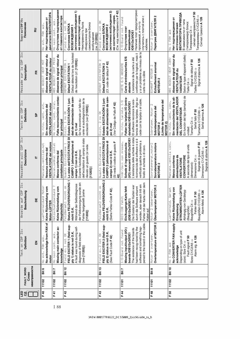
I 88
LE
D
СД
F
AU
LT
_WO
RD
Сл
ов
о
неи
спр
авн
ост
и
Text on CDP 31x
Def
init
ion
EN
Anzeige auf CDP 31x
Bes
chre
ibu
ng
DE
Messaggio sull CDP 31x
Des
criz
ion
e
IT
Texto en CDP 31x
Def
inic
ión
SP
Message sur la CDP 31x
Des
crip
tio
n
FR
CD
P 3
1x
По
ясн
ени
е
RU
F 4
0 11
102
Bit
6
No ext. FAN ack.
No
ack
no
wle
dg
e fr
om
FA
N o
f m
oto
r
Lueftermeldung Motor
Kei
ne
Rü
ckm
eld
un
g v
om
M
oto
r-L
ÜF
TE
R
Mancanz.ventilaz.mot
Nes
sun
a co
nfe
rma
dal
V
EN
TIL
AT
OR
E d
el m
oto
re
No rcto. vent. ext.
Sin
rec
on
oci
mie
nto
del
V
EN
TIL
AD
OR
del
mo
tor
ABS ACQUIT VENT MOT
Ab
sen
ce d
e si
gn
al r
eto
ur
du
V
EN
TIL
AT
EU
R d
u m
ote
ur
No ext. FAN ack.
Нет
по
дтв
ерж
ден
ия
от
дв
ига
тел
я В
ЕН
ТИ
ЛЯ
ТО
РА
F41
11
102
Bit
7
No main cont. ack.
Mis
sin
g m
ain
co
nta
cto
r ac
-kn
ow
led
ge
Netzschuetzmeldung ?
Kei
ne
Rü
ckm
eld
un
g v
om
H
aup
tsch
ütz
Mancan.segnal contat
Man
ca c
on
ferm
a d
al
con
tatt
ore
pri
nci
pal
e
No rcto. cont. pral.
Fal
ta r
eco
no
cim
ien
to c
on
tac-
tor
pri
nci
pal
ABS ACQUIT CONT PRIN
Ab
sen
ce d
e si
gn
al r
eto
ur
du
co
nta
cteu
r p
rin
cip
al
No main cont. ack.
Отс
утст
ви
е п
од
твер
жд
ени
я
от
глав
но
го к
он
так
тор
а
F 4
2 11
102
Bit
12
Field ex.1 not OK
FIE
LD
EX
CIT
ER
1 (
fiel
d s
up
-p
ly 1
) st
atu
s is
no
t O
.K.
A fa
ult w
as fo
und
durin
g se
lf-di
agno
sis
of fi
eld
exci
ter
see
[11
203]
)
Feldgeraet1 nicht ok
Sta
tus
FE
LD
VE
RS
OR
GU
NG
1n
ich
tO
.K.
Wäh
rend
der
Sel
bstd
iagn
ose
der
Fel
dver
sorg
ung
wur
de e
in
Feh
ler
fest
gest
ellt
sie
he
[112
03]
Guasto Eccitazione 1
Lo
sta
to d
ell’E
CC
ITA
TR
ICE
DI
CA
MP
O 1
(al
imen
tazi
on
e d
i ca
mp
o 1
) n
on
è O
.K.
Dur
ante
l’au
todi
agno
si
dell’
ecci
tatr
ice
di c
ampo
è s
tato
ril
evat
o un
gua
sto
si v
eda
[112
03])
Excit. 1 no OK
Est
ado
EX
CIT
AC
IÓN
1 (
un
i-d
ad d
e al
imen
taci
ón
de
cam
-p
o 1
) m
alS
e ha
enc
ontr
ado
un fa
llo d
u-ra
nte
el a
utod
iagn
óstic
o de
la
exci
taci
ón
ver
[112
03])
DEFAUT EXCITATION 1
Déf
aut
EX
CIT
AT
ION
1D
éfau
t dét
ecté
lors
de
l'aut
otes
t de
l'ex
cita
tion
cf.
[112
03])
Field ex.1 not OK
Со
сто
ян
ие
БЛ
ОК
А
ВО
ЗБ
УЖ
ДЕ
НИ
Я 1
(и
сто
чни
ка
во
збуж
ден
ия
1)
не
соо
твет
ств
ует
но
рм
е.
Неи
спра
внос
ть б
ыл
а об
нару
жен
а пр
и са
мок
онтр
оле
блок
а во
збуж
ден
ия
см
. [11
203]
)
F 4
3 11
102
Bit
13
Field ex.2 not OK
FIE
LD
EX
CIT
ER
2 (
fiel
d s
up
-p
ly 2
) st
atu
s is
no
t O
.K.
See
Fau
lt C
ode
F 4
2
Feldgeraet2 nicht ok
Sta
tus
FE
LD
VE
RS
OR
GU
NG
2n
ich
tO
.K.
Sie
he F
ehle
r-C
ode
F 4
2.
Guasto Eccitazione 2
Lo
sta
to d
ell’E
CC
ITA
TR
ICE
DI
CA
MP
O 2
(alim
enta
zio
ne
di
cam
po
2)
no
n è
O.K
. S
i ved
a il
codi
ce d
i gua
sto
F42
Excit. 2 no OK
Est
ado
EX
CIT
AC
IÓN
2 (
un
i-d
ad d
e al
imen
taci
ón
de
cam
-p
o 2
) m
al
Ver
Cód
igo
de F
allo
F 4
2
DEFAUT EXCITATION 2
Déf
aut
EX
CIT
AT
ION
2
Cf.
code
de
défa
ut F
42
Field ex.2 not OK
Со
сто
ян
ие
БЛ
ОК
А
ВО
ЗБ
УЖ
ДЕ
НИ
Я 2
(и
сто
чни
ка
во
збуж
ден
ия
2)
не
соо
твет
ств
ует
но
рм
е.
См
. код
неи
спра
внос
ти F
42
F 4
4 11
101
Bit
7
I/O-Board not found
Mis
sin
g in
pu
t/o
utp
ut
(I/O
-)
bo
ard
s IO
B1/
2x/3
/IOE
1T
he e
xist
ance
of t
he b
oard
s ha
d be
en r
ecog
-niz
ed b
y th
e so
ftwar
e an
d so
met
hing
hap
-pe
ned
to th
e bo
ard
or th
e ca
ble.
SDCS-IOB fehlt
Ein
/Au
sgan
gs-
Kar
te f
ehlt
(I
OB
1/2x
/3/IO
E1)
Die
Exi
sten
z de
r K
arte
n w
ar
durc
h di
e S
oftw
are
erka
nnt
wor
den,
abe
r da
nach
tritt
ein
F
ehle
r m
it de
r K
arte
ode
r de
m
Kab
el a
uf.
Ingr/Usci non presen.
Sch
ede
di i
ng
ress
o/u
scit
a (I
/O)
man
can
ti IO
B1/
2x/3
/IOE
1L'
esis
tenz
a de
lle s
ched
e è
stat
a ric
onos
ciut
a da
l sof
twar
e e
si è
ve
rific
ato
qual
che
prob
lem
a a
livel
lo d
i sch
eda
o di
cav
o.
No rcto. tarjeta I/O
Fal
tan
las
tarj
etas
I/O
(en
tra-
da/
salid
a) IO
B1/
2x/3
/IOE
1E
l sof
twar
e re
cono
ce la
exi
s-te
ncia
de
las
tarje
tas.
Alg
o su
-ce
de c
on la
tarje
ta o
el c
able
.
CARTE E/S ABSENTE
Car
te d
'en
trée
s/so
rtie
s E
/Sab
sen
teL’
exis
tenc
e de
la c
arte
a é
té
conf
irmée
par
le lo
gici
el, m
ais
il y
a un
pro
blèm
e au
niv
eau
de la
ca
rte
ou d
u câ
ble
I/O-Board not found
Отс
утст
ви
е п
лат
в
во
да/
вы
во
да
IOB
1/2x
/3/IO
E1
Нал
ичие
пл
ат п
ред
усм
отре
но
прог
рам
мой
, и ч
то-т
о сл
учил
ось
с пл
атой
ил
и с
кабе
лем
.
F 4
8 11
101
Bit
8
Motor 2 overtemp.
Ove
rtem
per
atu
re o
f M
OT
OR
2Motor 2 Uebertemp.
Üb
erte
mp
erat
ur
MO
TO
R 2
Sovratemperat.motor2
So
vrat
emp
erat
ura
mo
tore
M
OT
OR
E 2
Sobretemp. Motor 2
So
bre
tem
per
atu
ra d
el
MO
TO
R 2
(L
ímit
e d
e te
mp
erat
ura
del
M
OT
OR
2)
ECHAUFT MOTEUR 2
Ech
auff
emen
t an
orm
al
MO
TE
UR
2
Motor 2 overtemp.
Пер
егр
ев Д
ВИ
ГА
ТЕ
ЛЯ
2
F 5
0 11
102
Bit
10
No C FAN ack
No
CO
NV
ER
TE
R F
AN
su
pp
ly
ackn
ow
led
ge
D
epen
ding
on
type
of u
nit
(siz
e): S
ize
C4
F
ault
sign
al F
50
Siz
es C
1/C
2/A
5
Ala
rm s
ig. A
126
Lueftermeld. Geraet
Kei
ne
Rü
ckm
eld
un
g v
on
E
insp
eisu
ng
S
TR
OM
RIC
HT
ER
-LÜ
FT
ER
Abh
ängi
g vo
n G
erät
etyp
(B
augr
öße)
: B
augr
öße
C4
F
ehle
r-M
eld.
F 5
0B
augr
ößen
C1/
C2/
A5
A
larm
-Mel
d. A
126
Mancanz.ventila conv.
Man
ca c
on
ferm
a al
imen
tazi
on
e d
a V
EN
TIL
AT
OR
E
CO
NV
ER
TIT
OR
EA
sec
onda
del
tipo
di u
nità
(d
imen
sion
i):
Dim
ensi
one
C4
S
egna
le d
i gua
sto
F 5
0D
imen
sion
i C1/
C2/
A5
Seg
nale
di a
llarm
eA
126
No rcto. vent. conv.
Sin
rec
on
oci
mie
nto
de
la a
li-m
enta
ció
n d
el V
EN
TIL
AD
OR
D
EL
CO
NV
ER
TID
OR
En
func
ión
del t
ipo
(tam
año)
de
unid
ad:
Tam
año
C4
S
eñal
fallo
F 5
0T
amañ
os C
1/C
2/A
5
Señ
al a
larm
a A
126
ABS ACQUIT VENT CONV
Ab
sen
ce d
e si
gn
al r
eto
ur
du
V
EN
TIL
AT
EU
R d
u
VA
RIA
TE
UR
Sel
on le
type
d'a
ppar
eil (
taill
e) :
Tai
lle C
4
Sig
nal d
e dé
faut
F 5
0T
aille
s C
1/C
2/A
5
Sig
nal d
'ala
rme
A 1
26
No C FAN ack
Нет
по
дтв
ерж
ден
ия
от
ист
очн
ик
а п
ита
ни
я
ВЕ
НТ
ИЛ
ЯТ
ОР
А П
РИ
ВО
ДА
В
зав
исим
ости
от
типа
(т
ипор
азм
ера)
бл
ока:
Т
ипор
азм
ер С
4
си
гнал
неи
спра
внос
ти F
50
Тип
ораз
мер
ы C
1/C
2/A
5
С
игна
л т
рево
ги A
126
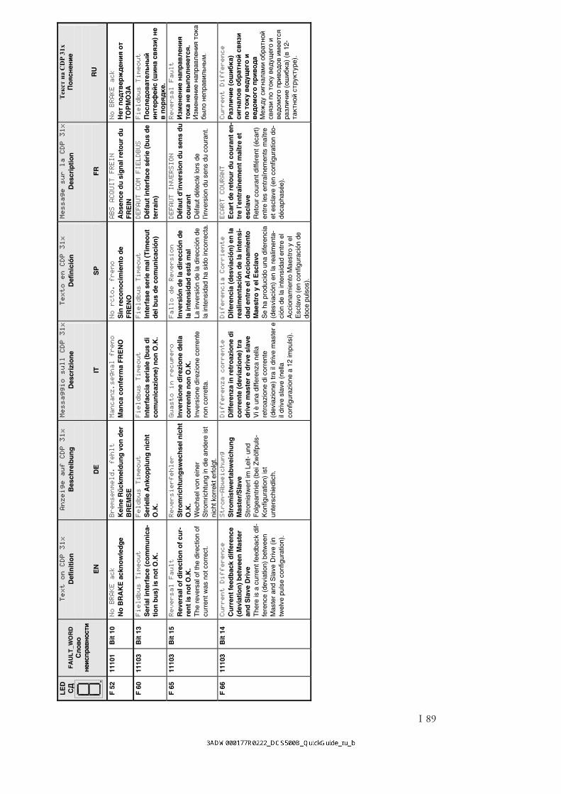
I 89
LE
D
СД
F
AU
LT
_WO
RD
Сл
ов
о
неи
спр
авн
ост
и
Text on CDP 31x
Def
init
ion
EN
Anzeige auf CDP 31x
Bes
chre
ibu
ng
DE
Messaggio sull CDP 31x
Des
criz
ion
e
IT
Texto en CDP 31x
Def
inic
ión
SP
Message sur la CDP 31x
Des
crip
tio
n
FR
CD
P 3
1x
По
ясн
ени
е
RU
F 5
2 11
101
Bit
10
No BRAKE ack
No
BR
AK
E a
ckn
ow
led
ge
Bremsenmeld. fehlt
Kei
ne
Rü
ckm
eld
un
g v
on
der
B
RE
MS
E
Mancanz.segnal freno
Man
ca c
on
ferm
a F
RE
NO
No rcto. freno
Sin
rec
on
oci
mie
nto
de
FR
EN
O
ABS ACQUIT FREIN
Ab
sen
ce d
u s
ign
al r
eto
ur
du
F
RE
IN
No BRAKE ack
Нет
по
дтв
ерж
ден
ия
от
ТО
РМ
ОЗ
А
F 6
0 11
103
Bit
13
Fieldbus Timeout
Ser
ial i
nte
rfac
e (c
om
mu
nic
a-ti
on
bu
s) is
no
t O
.K.
Feldbus Timeout
Ser
ielle
An
kop
plu
ng
nic
ht
O.K
.
Fieldbus Timeout
Inte
rfac
cia
seri
ale
(bu
s d
i co
mu
nic
azio
ne)
no
n O
.K.
Fieldbus Timeout
Inte
rfas
e se
rie
mal
(T
imeo
ut
del
bu
s d
e co
mu
nic
ació
n)
DEFAUT COM FIELDBUS
Déf
aut
inte
rfac
e sé
rie
(bu
s d
e te
rrai
n)
Fieldbus Timeout
По
след
ов
ател
ьн
ый
и
нте
рф
ейс
(ши
на
свя
зи)
не
в п
ор
яд
ке.
F
65
1110
3B
it 1
5 Reversal Fault
Rev
ersa
l of
dir
ecti
on
of
cur-
ren
t is
no
t O
.K.
The
rev
ersa
l of t
he d
irect
ion
of
curr
ent w
as n
ot c
orre
ct.
Reversierfehler
Str
om
rich
tun
gsw
ech
seln
ich
tO
.K.
Wec
hsel
von
ein
er
Str
omric
htun
g in
die
and
ere
ist
nich
t kor
rekt
erf
olgt
.
Guasto in recupero
Inve
rsio
ne
dir
ezio
ne
del
la
corr
ente
no
n O
.K.
Inve
rsio
ne d
irezi
one
corr
ente
no
n co
rret
ta.
Fallo de Reversion
Inve
rsió
n d
e la
dir
ecci
ón
de
la in
ten
sid
ad e
stá
mal
La in
vers
ión
de la
dire
cció
n de
la
inte
nsid
ad h
a si
do in
corr
ecta
.
DEFAUT INVERSION
Déf
aut
d'in
vers
ion
du
sen
s d
u
cou
ran
tD
éfau
t dét
ecté
lors
de
l’inv
ersi
on d
u se
ns d
u co
uran
t.
Reversal Fault
Изм
енен
ие
нап
рав
лен
ия
то
ка
не
вы
по
лн
яет
ся.
Изм
енен
ие н
апра
влен
ия т
ока
был
о не
прав
ильн
ым
.
F 6
6 11
103
Bit
14
Current Difference
Cu
rren
t fe
edb
ack
dif
fere
nce
(d
evia
tio
n)
bet
wee
n M
aste
r an
d S
lave
Dri
ve
The
re is
a c
urre
nt fe
edba
ck d
if-fe
renc
e (d
evia
tion)
bet
wee
n M
aste
r an
d S
lave
Driv
e (in
tw
elve
pul
se c
onfig
urat
ion)
.
Strom-Abweichung
Str
om
istw
erta
bw
eich
un
g
Mas
ter/
Sla
veS
trom
istw
ert i
m L
eit-
und
F
olge
antr
ieb
(bei
Zw
ölfp
uls-
Kon
figur
atio
n) is
t un
ters
chie
dlic
h.
Differenza corrente
Dif
fere
nza
in r
etro
azio
ne
di
corr
ente
(d
evia
zio
ne)
tra
d
rive
mas
ter
e d
rive
sla
ve
Vi è
una
diff
eren
za n
ella
re
troa
zion
e di
cor
rent
e (d
evia
zion
e) tr
a il
driv
e m
aste
r e
il dr
ive
slav
e (n
ella
co
nfig
uraz
ione
a 1
2 im
puls
i).
Diferencia Corriente
Dif
eren
cia
(des
viac
ión
) en
la
real
imen
taci
ón
de
la in
ten
si-
dad
en
tre
el A
ccio
nam
ien
to
Mae
stro
y e
l Esc
lavo
S
e ha
pro
duci
do u
na d
ifere
ncia
(d
esvi
ació
n) e
n la
rea
limen
ta-
ción
de
la in
tens
idad
ent
re e
l A
ccio
nam
ient
o M
aest
ro y
el
Esc
lavo
(en
con
figur
ació
n de
do
ce p
ulso
s).
ECART COURANT
Eca
rt d
e re
tou
r d
u c
ou
ran
t en
-tr
e l’e
ntr
aîn
emen
t m
aîtr
e et
es
clav
e R
etou
r co
uran
t diff
éren
t (éc
art)
en
tre
les
entr
aîne
men
ts m
aîtr
e et
esc
lave
(en
con
figur
atio
n do
-dé
caph
asée
).
Current Difference
Раз
ли
чие
(ош
иб
ка)
си
гнал
ов
об
рат
но
й с
вя
зи
по
то
ку
вед
ущег
о и
в
едо
мо
го п
ри
во
да
Меж
ду
сигн
алам
и об
ратн
ой
связ
и по
ток
у ве
дущ
его
и ве
дом
ого
прив
одов
им
еетс
я ра
злич
ие (
ошиб
ка)
(в 1
2-та
ктно
й ст
рукт
уре)
.
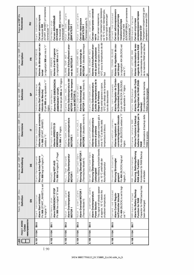
I 90
LE
D
FA
UL
T_W
OR
D
Сл
ов
о
неи
спр
авн
ост
и
Text on CDP 31x
Def
init
ion
EN
Anzeige auf CDP 31x
Bes
chre
ibu
ng
DE
Messaggio sull CDP 31x
Des
criz
ion
e
IT
Texto en CDP 31x
Def
inic
ión
SP
Message sur la CDP 31x
Des
crip
tio
n
FR
CD
P 3
1x
По
ясн
ени
е
RU
A 1
01 1
1104
Bit
0
Start inhibition
Ala
rm S
tart
Inh
ibit
ion
P
in 9
08 (
ST
AR
T_I
NH
IBIT
) is
set
to
logi
cal "
1“
Start-Verhinderung
War
nu
ng
An
lau
f-S
per
reP
in 9
08 li
egt a
uf lo
gisc
h „1
“
Partenza inibita
Alla
rme
inib
izio
ne
avvi
amen
to
Pin
908
(S
TA
RT
_IN
HIB
IT)
setta
to a
"1“
.
Inhibicion Arranque
Ala
rma
Sta
rt In
hib
itio
n (
In-
hib
ició
n d
e M
arch
a)
El p
in 9
08 s
e ha
aju
stad
o a
"1“
lógi
co.
MARCHE NON AUTORISE
Ala
rme
de
dém
arra
ge
no
n a
u-
tori
sé
Le s
igna
l/pin
908
est
mis
à "
1"
Start inhibition
Си
гнал
зап
рет
а п
уск
а Н
а вы
вод
е 90
8 (S
TA
RT
_IN
HIB
IT)
уста
новл
ена
лог
ичес
кая
"1"
A 1
02 1
1104
Bit
1
Emergency stop
Ala
rm E
ME
RG
EN
CY
ST
OP
P
in 9
06 h
as a
logi
cal "
0" le
vel
Nothalt
War
nu
ng
NO
T-A
US
Pin
906
hat
logi
sch
„0“
Peg
el
Arresto emergenza
Alla
rme
AR
RE
ST
O D
I E
ME
RG
EN
ZA
P
in 9
06 a
"0"
logi
co.
Paro emergencia
Ala
rma
PA
RO
EM
ER
GE
NC
IA
(EM
ER
GE
NC
Y S
TO
P)
El n
ivel
del
pin
906
es
"0"
lógi
co
ARRET URGENCE
Ala
rme
d'a
rrêt
d'u
rgen
ce
Le s
igna
l/pin
906
est
à "
0".
Emergency stop
Си
гнал
АВ
АР
ИЙ
НЫ
Й
ОС
ТА
НО
В
На
выво
де
906
уста
новл
ен
лог
ичес
кий
"0"
A
103
111
04B
it 2
Motor 1 temp. alarm
Ala
rm O
vert
emp
erat
ure
M
OT
OR
1
Mot.1 Temp Warnung
War
nu
ng
Üb
erte
mp
erat
ur
MO
TO
R 1
Alarm.temp.motore 1
Alla
rme
sovr
atem
per
atu
raM
OT
OR
E 1
Alarma temp. mot. 1
Ala
rma
So
bre
tem
per
atu
ra d
el
MO
TO
R 1
(L
ímit
e d
e te
mp
era-
tura
del
MO
TO
R 1
)
ALARME TEMP MOT 1
Ala
rme
d'é
chau
ffem
ent
ano
r-m
al d
u M
OT
EU
R 1
Motor 1 temp. alarm
Си
гнал
пер
егр
ева
ДВ
ИГ
АТ
ЕЛ
Я 1
A 1
04 1
1104
Bit
3
Motor 1 overl.alarm
Ala
rm O
verl
oad
MO
TO
R 1
(T
herm
al M
odel
1)
Mot.1 Ueberlast-Warn
War
nu
ng
Üb
erla
st M
OT
OR
1
(The
rmis
ches
Mod
ell 1
)
Alarm. sovrac.mot.1
Alla
rme
sovr
acca
rico
M
OT
OR
E 1
(M
odel
lo te
rmic
o 1)
Alarm.sobrecar.mot1
Ala
rma
So
bre
carg
a d
el
MO
TO
R 1
(M
odel
o T
érm
ico
1)
ALARME SURCHAR MOT1
Ala
rme
de
surc
har
ge
du
M
OT
EU
R 1
(M
odèl
e th
erm
ique
1)
Motor 1 overl.alarm
Си
гнал
пер
егр
узк
и
ДВ
ИГ
АТ
ЕЛ
Я 1
(Т
епл
овая
мод
ель
1)
A 1
05 1
1104
Bit
4
Conv. overtemp. alarm
Ala
rm O
vert
emp
erat
ure
P
ow
er S
ecti
on
T
his
sign
al w
ill a
lread
y ap
pear
at
app
rox.
10
°C b
elow
the
shut
dow
n te
mpe
ratu
re.
Geraet Uebertemp-Warn
War
nu
ng
Üb
erte
mp
erat
ur
Lei
stu
ng
stei
lD
iese
Mel
dung
ers
chei
nt b
erei
ts
ca. 1
0 °C
unt
erha
lb d
er
Abs
chal
ttem
pera
tur
Alarm.sovrtemp.conv.
Alla
rme
sovr
atem
per
atu
ra
sezi
on
e d
i po
ten
za
Que
sto
segn
ale
com
pare
già
a
circ
a 10
°C
al d
isot
to d
ella
te
mpe
ratu
ra d
i blo
cco.
Alarm.sobrtemp.conv
Ala
rma
So
bre
tem
per
atu
ra
(Lím
ite
de
tem
per
atu
ra)
de
la
Eta
pa
de
Po
ten
cia
Est
a se
ñal a
pare
ce a
apr
ox.
10°C
por
deb
ajo
de la
tem
pera
-tu
ra d
e de
scon
exió
n
ALARME ECHAUFT MOT1
Ala
rme
d'é
chau
ffem
ent
ano
r-m
al d
u p
on
t d
e p
uis
san
ceL'
alar
me
est s
igna
lée
à en
viro
n 10
°C s
ous
la te
mpé
ratu
re d
e dé
-fa
ut
Conv. overtemp. alarm
Си
гнал
пер
егр
ева
сил
ов
ой
ча
сти
Э
тот
сигн
ал п
оявл
яетс
я,
когд
а те
мпе
рату
ра п
рим
ерно
на
10
°C н
иже
тем
пера
туры
, пр
и ко
торо
й пр
оисх
одит
от
клю
чени
е.
A 1
06 1
1104
Bit
5
Current reg blocked
Ala
rm C
urr
ent
Reg
ula
-to
r/C
on
tro
ller
blo
cked
P
in 4
04 (
BLO
CK
) is
set
to lo
gi-
cal "
1“.
Stromregl blockiert
War
nu
ng
Str
om
reg
ler
ges
per
rt
Pin
404
(B
LOC
K)
liegt
auf
lo
gisc
h „1
“.
Bloc.regltor.corren.
Alla
rme
reg
ola
tore
di
corr
ente
/reg
ola
tore
blo
ccat
o
Pin
404
(B
LOC
CO
) se
ttato
a "
1“
logi
co.
Reg. corr.bloqueado
Ala
rma
Reg
ula
do
r d
e C
orr
ien
-te
(In
ten
sid
ad)
blo
qu
ead
o
El p
in 4
04 B
LOC
K (
BLO
QU
E)
está
aju
stad
o a
"1“
lógi
co.
REGUL COURAN BLOQUE
Ala
rme
de
rég
ula
teu
r d
e co
u-
ran
t b
loq
ué
Le s
igna
l/pin
404
(B
LOC
K)
est
mis
à "
1".
Current reg blocked
Си
гнал
заб
ло
ки
ро
ван
но
го
сост
оя
ни
я р
егул
ято
ра
ток
а/к
он
тро
лл
ера
На
выво
де
404
(БЛ
ОК
ИР
ОВ
КА
) ус
тано
влен
а л
огич
еска
я "1
"
A 1
08 1
1104
Bit
7
RAM-backup failed
Ala
rm N
o B
atte
ry B
acku
p
Fu
nct
ion
fo
r R
AM
C
apac
itor
for
RA
M b
acku
p ha
s be
en d
isch
arge
d.
RAM Speicherfehler
War
nu
ng
, Bat
teri
epu
ffer
un
g
RA
M a
uß
er F
un
ktio
n
Kon
dens
ator
für
RA
M B
acku
p is
t ent
lade
n
Allarme lettura RAM
Alla
rme
Fu
nzi
on
e d
i bac
kup
b
atte
ria
no
n d
isp
on
ibile
per
la
RA
M
Il co
nden
sato
re d
i bac
kup
della
R
AM
è s
caric
o.
Fallo RAM-Backup
Ala
rma
Sin
Fu
nci
ón
de
Co
pia
d
e S
egu
rid
ad d
e R
AM
(R
AM
-b
acku
p)
El c
onde
nsad
or d
e la
mem
oria
R
AM
se
ha d
esca
rgad
o.
DEFAUT LECTURE RAM
Ala
rme
con
den
sate
ur
de
sau
-ve
gar
de
de
la m
émo
ire
RA
M
Le c
onde
nsat
eur
de s
auve
gard
e de
la m
émoi
re R
AM
est
déc
har-
gé.
RAM-backup failed
Си
гнал
отс
утст
ви
я
рез
ерв
ир
ов
ани
я б
атар
еи
пи
тан
ия
ОЗ
У
Раз
ряд
ился
кон
ден
сато
р д
ля
резе
рвно
го п
итан
ия О
ЗУ
.
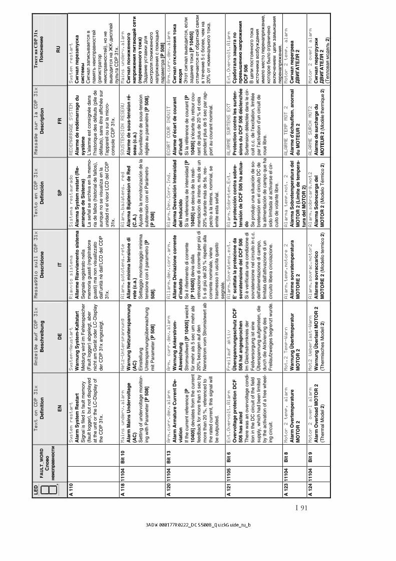
I 91
LE
D
FA
UL
T_W
OR
D
Сл
ов
о
неи
спр
авн
ост
и
Text on CDP 31x
Def
init
ion
EN
Anzeige auf CDP 31x
Bes
chre
ibu
ng
DE
Messaggio sull CDP 31x
Des
criz
ion
e
IT
Texto en CDP 31x
Def
inic
ión
SP
Message sur la CDP 31x
Des
crip
tio
n
FR
CD
P 3
1x
По
ясн
ени
е
RU
A 1
10
System restart
Ala
rm S
yste
m R
esta
rt
Sig
nal i
s fil
ed in
faul
t mem
ory
(fau
lt lo
gger
), b
ut n
ot d
ispl
ayed
at
the
unit
or th
e LC
-Dis
play
of
the
CD
P 3
1x.
System-Neustart
War
nu
ng
Sys
tem
-Kal
tsta
rtM
eldu
ng w
ird im
Feh
lers
peic
her
(Fau
lt lo
gger
) ab
gele
gt, a
ber
nich
t am
Ger
ät o
der
LC-D
ispl
ay
der
CD
P 3
1x a
ngez
eigt
.
Riavvio sistema
Alla
rme
Ria
vvia
men
to s
iste
ma
Seg
nale
reg
istr
ato
nella
m
emor
ia g
uast
i (re
gist
rato
re
guas
ti) m
a no
n vi
sual
izza
to
dall’
unità
nè
dall’
LCD
del
CD
P
31x.
Sistema restaurado
Ala
rma
Sys
tem
res
tart
(R
e-ar
ran
qu
e d
e S
iste
ma)
La
señ
al s
e ar
chiv
a en
la m
emo-
ria d
e fa
llos
(his
toria
l de
fallo
s),
aunq
ue n
o se
vis
ualiz
a en
la
unid
ad n
i el v
isor
LC
D d
el C
DP
31
x.
REDEMARRAGE SYSTEM
Ala
rme
de
red
émar
rag
e d
u
syst
ème
L'al
arm
e es
t con
sign
ée d
ans
l’his
toriq
ue d
es d
éfau
ts (
pile
de
défa
uts)
, san
s êt
re a
ffich
ée s
ur
l’app
arei
l ou
sur
la m
icro
-co
nsol
e C
DP
31x
.
System restart
Си
гнал
пер
езап
уск
а си
стем
ы
Сиг
нал
зап
исы
вает
ся в
па
мят
ь не
испр
авно
стей
(р
егис
трат
ор
неис
прав
ност
ей),
но
не
выво
дит
ся н
а Ж
К-д
испл
ей
пул
ьта
CD
P 3
1x.
A 1
18 1
1104
Bit
10
Mains underv.alarm
Ala
rm M
ain
s U
nd
ervo
ltag
e (A
C)
Set
ting
of u
nder
volta
ge m
onito
r-in
g w
ith P
aram
eter
[P
508
]
Netz-Unterspannung
War
nu
ng
Net
zun
ters
pan
nu
ng
(A
C)
Ein
stel
lung
U
nter
span
nung
sübe
rwac
hung
m
it P
aram
eter
[P
508
]
Alarm.sototens.rete
Alla
rme
min
ima
ten
sio
ne
di
rete
(c.
a.)
Set
tagg
io m
onito
ragg
io m
inim
a te
nsio
ne c
on il
par
amet
ro [
P50
8].
Alarm.bajatens. red
Ala
rma
Baj
aten
sio
n d
e R
ed
(C.A
.)
Aju
ste
de la
mon
itoriz
ació
n de
la
subt
ensi
ón c
on e
l Par
ámet
ro
[P 5
08]
SOUSTENSION RESEAU
Ala
rme
de
sou
s-te
nsi
on
ré-
seau
(c.
a.)
Sur
veill
ance
de
sous
-ten
sion
ré
glée
au
para
mèt
re [
P 5
08].
Mains underv.alarm
Си
гнал
по
ни
жен
но
го
нап
ря
жен
ия
пи
таю
щей
сет
и
(пер
емен
но
го т
ок
а)
Зад
ание
уст
авки
дл
я ко
нтро
ля
пони
жен
ного
на
пряж
ения
с п
омощ
ью
пара
мет
ра [
P 5
08]
A 1
20 1
1104
Bit
13
Arm.curr.dev.alarm
Ala
rm A
rmat
ure
Cu
rren
t D
e-vi
atio
n
If th
e cu
rren
t ref
eren
ce [
P10
405]
dev
iate
s fr
om th
e cu
rren
t fe
edba
ck fo
r m
ore
than
5 s
ec b
y m
ore
than
20
%, r
efer
ence
d to
th
e ra
ted
curr
ent,
this
sig
nal w
ill
be o
utpu
tted.
Arm. curr.dev.alarm
War
nu
ng
An
kers
tro
m-
Ab
wei
chu
ng
S
trom
sollw
ert [
P 1
0405
] w
eich
t fü
r m
ehr
als
5 se
c um
meh
r al
s 20
% b
ezog
en a
uf d
en
Nen
nstr
om v
om S
trom
istw
ert a
b
Allarm.dev.corr.arm.
Alla
rme
Dev
iazi
on
e co
rren
te
d’in
do
tto
S
e il
rifer
imen
to d
i cor
rent
e [P
104
05]
devi
a da
lla
retr
oazi
one
di c
orre
nte
per
più
di
5 s
di p
iù d
el 2
0 %
ris
petto
alla
co
rren
te n
omin
ale,
vie
ne
tras
mes
so in
usc
ita q
uest
o se
gnal
e.
Alarm.Dev.Corr.Ind.
Ala
rma
Des
viac
ión
Inte
nsi
dad
d
el In
du
cid
o
Si l
a re
fere
ncia
de
inte
nsid
ad [
P10
405]
se
desv
ía d
e la
rea
li-m
enta
ción
de
inte
ns. m
ás d
e un
20
% d
uran
te m
ás d
e 5s
. res
-pe
cto
a la
inte
ns. n
omin
al, s
e em
ite e
sta
seña
l.
ECART COUR INDUIT
Ala
rme
d'é
cart
de
cou
ran
t d
'ind
uit
S
i la
réfé
renc
e de
cou
rant
[P
1040
5] s
'éca
rte
du r
etou
r co
u-ra
nt d
e pl
us d
e 20
% e
t cel
a pe
ndan
t plu
s de
5 s
ec p
ar r
ap-
port
au
cour
ant n
omin
al.
Arm.curr.dev.alarm
Си
гнал
отк
ло
нен
ия
то
ка
як
ор
я
Это
т си
гнал
вы
вод
ится
, есл
и за
дан
ие т
ока
[P 1
0405
] от
лич
аетс
я от
обр
атно
й св
язи
в те
чени
е 5
с бо
лее
, чем
на
20%
от
ном
инал
ьног
о то
ка.
A 1
21 1
1105
Bit
6
Ext.Overvolt.Alarm
Ove
rvo
ltag
e p
rote
ctio
n D
CF
50
6 h
as a
cted
T
here
was
an
over
volta
ge c
ondi
-tio
n in
the
DC
circ
uit o
f the
fiel
d su
pply
, whi
ch h
ad b
een
limite
d by
the
activ
atio
n of
a fr
ee w
heel
-in
g ci
rcui
t.
Freilauf aktiv
Üb
ersp
ann
un
gss
chu
tz D
CF
50
6 h
at a
ng
esp
roch
en
Im G
leic
hstr
omkr
eis
der
Fel
dver
sorg
ung
ist e
ine
Übe
rspa
nnun
g au
fget
rete
n, d
ie
durc
h di
e A
ktiv
ieru
ng d
es
Fre
ilauf
zwei
ges
begr
enzt
wur
de.
Alarm.Sovratens.ext.
E' s
catt
ata
la p
rote
zio
ne
da
sovr
aten
sio
ne
del
DC
F 5
06S
i è v
erifi
cata
una
con
dizi
one
di
sovr
aten
sion
e ne
l circ
uito
in c
.c.
dell'
alim
enta
zion
e di
cam
po,
limita
ta d
all'a
ttiva
zion
e di
un
circ
uito
libe
ra c
ircol
azio
ne.
Alarm.Sobreten.Ext.
La
pro
tecc
ión
co
ntr
a so
bre
-te
nsi
ón
de
DC
F 5
06 h
a ac
tua-
do
Se
prod
ujo
una
situ
ació
n de
so-
bret
ensi
ón e
n el
circ
uito
DC
de
la a
limen
taci
ón d
e ca
mpo
que
ha
sido
lim
itada
al a
ctiv
arse
el c
ir-cu
ito d
e vo
lant
e lib
re.
ALARME SURTENS EXT
Pro
tect
ion
co
ntr
e le
s su
rten
-si
on
s d
u D
CF
506
déc
len
chée
Sur
tens
ion
déte
ctée
dan
s le
cir-
cuit
c.c.
de
l’exc
itatio
n, li
mité
e pa
r l’a
ctiv
atio
n d’
un c
ircui
t de
roue
libr
e.
Ext.Overvolt.Alarm
Ср
або
тал
а за
щи
та п
о
пр
евы
шен
ию
нап
ря
жен
ия
D
CF
506
В
цеп
и по
стоя
нног
о то
ка
исто
чник
а во
збуж
ден
ия
имел
о м
есто
пер
енап
ряж
ение
, ко
торо
е бы
ло
огра
ниче
но
вкл
юче
нием
цеп
и за
мы
кани
я пе
рена
пряж
ения
. A
123
111
04B
it 8
Motor 2 temp. alarm
Ala
rm O
vert
emp
erat
ure
M
OT
OR
2
Mot.2 Temp-Warn
War
nu
ng
Üb
erte
mp
erat
ur
MO
TO
R 2
Alarm.temp.motore 2
Alla
rme
sovr
atem
per
atu
ra
MO
TO
RE
2
Alarma temp.mot. 2
Ala
rma
So
bre
tem
per
atu
ra d
el
MO
TO
R 2
(L
ímit
e d
e te
mp
era-
tura
del
MO
TO
R 2
)
ALARME TEMP MOT 2
Ala
rme
d'é
chau
ffem
. an
orm
al
du
MO
TE
UR
2
Motor 2 temp. alarm
Си
гнал
пер
егр
ева
ДВ
ИГ
АТ
ЕЛ
Я 2
A 1
24 1
1104
Bit
9
Motor 2 overl alarm
Ala
rm O
verl
oad
MO
TO
R 2
(T
herm
al M
odel
2)
Mot2 Ueberlast-Warn
War
nu
ng
Üb
erla
st M
OT
OR
2
(The
rmis
ches
Mod
ell 2
)
Alarm.sovrac.motor2
Alla
rme
sovr
acca
rico
MO
TO
RE
2 (
Mod
ello
term
ico
2)
Alarm.sobrcarg.mot2
Ala
rma
So
bre
carg
a d
el
MO
TO
R 2
(M
odel
o T
érm
ico
2)
ALARME SURCH MOT2
Ala
rme
de s
urch
arge
du
MO
TEU
R 2
(Mod
èle
ther
miq
ue 2
)
Motor 2 overl alarm
Си
гнал
пер
егр
узк
и
ДВ
ИГ
АТ
ЕЛ
Я 2
(Т
епл
овая
мод
ель
2)
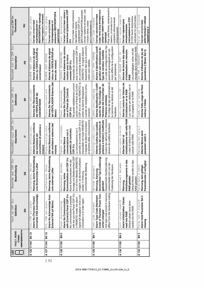
I 92
LE
D
FA
UL
T_W
OR
D
Сл
ов
о
неи
спр
авн
ост
и
Text on CDP 31x
Def
init
ion
EN
Anzeige auf CDP 31x
Bes
chre
ibu
ng
DE
Messaggio sull CDP 31x
Des
criz
ion
e
IT
Texto en CDP 31x
Def
inic
ión
SP
Message sur la CDP 31x
Des
crip
tio
n
FR
CD
P 3
1x
По
ясн
ени
е
RU
A 1
26 1
1104
Bit
12
Conv.FAN ack.alarm
Ala
rm N
o (
Th
yris
tor
Po
wer
) C
on
vert
er F
AN
Ack
no
wle
dg
e
Lueftermeld. Geraet
War
nu
ng
, kei
ne
Rü
ckm
eld
un
g
vom
Str
om
rich
ter-
Lü
fter
Alarm.ventilaz.conv
Alla
rme
Nes
sun
a co
nfe
rma
dal
ven
tila
tore
del
co
nve
rtit
ore
(d
i po
ten
za a
ti
rist
ori
)
Alrm.rcto.vent.conv
Ala
rma
Sin
Rec
on
oci
mie
nto
d
el V
EN
TIL
AD
OR
del
C
ON
VE
RT
IDO
R
ALARME VENT CONV
Ala
rme
d'a
bse
nce
de
sig
nal
re
tou
r d
u V
EN
TIL
AT
EU
R d
u
con
vert
isse
ur
Conv.FAN ack.alarm
Си
гнал
отс
утст
ви
я
по
дтв
ерж
ден
ия
от
ВЕ
НТ
ИЛ
ЯТ
ОР
А п
ри
во
да
(ти
ри
сто
рн
ого
пи
тан
ия
)
A 1
27 1
1104
Bit
15
Ext. FAN ack.alarm
Ala
rm N
o A
ckn
ow
led
ge
fro
m
Ext
ern
al F
AN
(o
f M
oto
r)
Lueftermeld. Motor
War
nu
ng
, kei
ne
Rü
ckm
eld
un
g
vom
ext
ern
en L
üft
er
Alarm.ventilaz.moto
Alla
rme
Nes
sun
a co
nfe
rma
dal
ven
tila
tore
est
ern
o (
del
m
oto
re)
Alarm.rcto.vent.ext
Ala
rma
Sin
Rec
on
oci
mie
nto
d
el V
EN
TIL
AD
OR
Ext
ern
o (
del
M
oto
r)
ALARME VENT MOTEUR
Ala
rme
d'a
bse
nce
de
sig
nal
re
tou
r d
u V
EN
TIL
AT
EU
R e
x-te
rne
(du
mo
teu
r)
Ext. FAN ack.alarm
Си
гнал
отс
утст
ви
я
по
дтв
ерж
ден
ия
от
вн
ешн
его
ВЕ
НТ
ИЛ
ЯТ
ОР
А
(дв
ига
тел
я)
A 1
28 1
1105
Bit
0
Panel disconnected
Ala
rm N
o C
om
mu
nic
atio
n
wit
h (
Co
ntr
ol)
Pan
el C
DP
31x
N
o co
mm
unic
aito
n is
pos
sibl
e w
ith th
e co
n-tr
ol P
anel
CD
P 3
1x
in R
EM
OT
E m
ode;
the
alar
m
sign
al w
ill d
isap
pear
onc
e co
m-
mun
icat
ion
is in
ord
er a
gain
.
Bedienpanel gezogen
War
nu
ng
, kei
ne
Ko
mm
un
ikat
ion
mit
CD
P 3
1x
Kei
ne K
omm
unik
atio
n m
it de
r A
nzei
ge u
nd B
edie
nein
heit
CD
P
31x
im F
ern-
Bet
rieb
(RE
MO
TE
) m
öglic
h; is
t die
Kom
mun
ikat
ion
wie
der
in O
rdnu
ng,
vers
chw
inde
t die
Mel
dung
.
Pannel non collegat.
Alla
rme
Man
ca
com
un
icaz
ion
e co
n il
p
ann
ello
(d
i co
ntr
ollo
) C
DP
31x
La
com
unic
azio
ne c
on il
pa
nnel
lo d
i con
trol
lo C
DP
31x
è
impo
ssib
ile n
el m
odo
RE
MO
TE
; il
segn
ale
di a
llarm
e sc
ompa
re
al r
ipris
tino
della
com
unic
azio
ne.
Panel desconectado
Ala
rma
Sin
Co
mu
nic
ació
n
con
el P
anel
(d
e C
on
tro
l)
CD
P 3
1x
No
pued
e es
tabl
ecer
se c
omun
i-ca
ción
con
el P
anel
de
Con
trol
C
DP
31x
en
mod
o R
EM
OT
O; l
a se
ñal d
e al
arm
a de
sapa
rece
cu
ando
se
rest
able
ce la
com
u-ni
caci
ón.
CONSOLE DECONNECTEE
Ala
rme
d'a
bse
nce
de
com
mu
-n
icat
ion
ave
c la
mic
ro-
con
sole
CD
P 3
1x
Impo
ssib
le d
e co
mm
uniq
uer
avec
la m
icro
-con
sole
CD
P 3
1x
en c
omm
ande
à d
ista
nce
(RE
MO
TE
) ; l
e si
gnal
d'a
larm
e di
spar
aîtr
a dè
s qu
e la
com
mun
i-ca
tion
sera
rét
ablie
.
Panel disconnected
Си
гнал
отс
утст
ви
я с
вя
зи с
п
анел
ью
(уп
рав
лен
ия
) C
DP
31
x О
тсут
стви
е св
язи
возм
ожно
пр
и ра
боте
пан
ели
упра
влен
ия C
DP
31x
в
ДИ
СТ
АН
ЦИ
ОН
НО
М р
ежим
е;
сигн
ал т
рево
ги и
счез
ает,
как
то
льк
о св
язь
снов
а во
сста
навл
ивае
тся.
A
129
111
05B
it 1
Type code changed
Ala
rm T
ype
Co
de
(Har
dw
are
Co
de
of
Th
yris
tor
Po
wer
Co
n-
vert
er)
chan
ged
U
nit t
ype
code
sto
red
in m
emor
y di
ffers
from
the
hard
war
e co
din g
.
HW-Code geaendert
War
nu
ng
, Ken
nu
ng
S
tro
mri
chte
r-T
yp (
Co
die
run
g)
geä
nd
ert
Ges
peic
hert
e G
erät
ecod
ieru
ng
unte
rsch
eide
t sic
h vo
n de
r C
odie
rung
der
Har
dwar
e.
Sostituz.codic.conv.
Alla
rme
Co
dic
e ti
po
(co
dic
e h
ard
war
e d
el c
on
vert
ito
re d
i p
ote
nza
a t
iris
tori
) m
od
ific
ato
C
odic
e tip
o de
ll’un
ità in
mem
oria
di
vers
o da
cod
ifica
har
dwar
e.
Ident.conv.cambiada
Ala
rma
Iden
tifi
caci
ón
/ C
od
ifi-
caci
ón
de
Tip
o (
Có
dig
o d
e H
ard
war
e d
el C
on
vert
ido
r d
e P
ote
nci
a ca
mb
iad
a E
l cód
igo
de ti
po a
lmac
enad
o en
la
mem
oria
es
dist
into
al d
el
hard
war
e.
IDENTIF CONV CHANGE
Ala
rme
d’id
enti
fica
tio
n (
con
fi-
gu
rati
on
par
rés
ista
nce
s) d
u
typ
e d
e va
riat
eur
mo
dif
iée
Le c
ode
de c
onfig
urat
ion
de l'
ap-
pare
il te
l qu'
enre
gist
ré e
n m
é-m
oire
diff
ère
de la
con
figur
atio
n pa
r ré
sist
ance
s.
Type code changed
Си
гнал
нес
оо
твет
ств
ия
к
од
а ти
па
(ко
д а
пп
арат
ны
х ср
едст
в т
ир
ист
ор
но
го
пр
ив
од
а)
Код
тип
а бл
ока,
зап
исан
ный
в па
мят
ь, о
тлич
аетс
я от
ко
дов
ого
обоз
наче
ния
обор
удов
ания
. A
130
111
05B
it 2
Init values read,S2
Ala
rm In
itia
lizia
tio
n V
alu
es
read
into
RA
M
Def
ault
valu
es h
ave
been
lo
aded
into
the
RA
M.
Initialwert geladen
War
nu
ng
, In
itia
lisie
run
gsw
erte
in d
as
RA
M g
elad
en
Def
ault-
Wer
te w
urde
n in
das
R
AM
gel
aden
.
Letur.valor.iniz.S2
Alla
rme
Val
ori
di
iniz
ializ
zazi
on
e le
tti n
ella
RA
M
I val
ori d
i def
ault
sono
sta
ti ca
ricat
i nel
la R
AM
.
Lect.valore inic.S2
Ala
rma
Lec
tura
de
Val
ore
s d
e In
icia
lizac
ión
en
la R
AM
Lo
s va
lore
s po
r de
fect
o ha
n si
-do
car
gado
s en
la R
AM
.
LECT VALEUR INIT S2
Ala
rme
de
lect
ure
des
val
eurs
d
’init
ialis
atio
n e
n m
émo
ire
RA
M
Les
prér
égla
ges
usin
e on
t été
ch
argé
s da
ns la
mém
oire
RA
M.
Init values read,S2
Си
гнал
пар
амет
ро
в
ин
иц
иал
иза
ци
и,
счи
тыв
аем
ых
из
ОЗ
У
В О
ЗУ
бы
ли
загр
ужен
ы
знач
ения
по
умол
чани
ю.
A 1
32 1
1105
Bit
3
Param set 2 missing
Ala
rm V
alid
Par
amet
er S
et 2
m
issi
ng
Param-Satz 2 fehlt
War
nu
ng
, kei
n g
ült
iger
P
aram
eter
satz
2 v
erfü
gb
ar
Mancanza Set para.2
Alla
rme
Man
ca s
erie
p
aram
etri
val
idi 2
Juego par.2 perdido
Ala
rma
Fal
ta J
ueg
o d
e P
ará-
met
ros
2 V
álid
o
JEU PAR 2 MANQUANT
Ala
rme
d'a
bse
nce
de
jeu
de
par
amèt
res
2 [M
oto
r S
et 2
]
Param set 2 missing
Си
гнал
отс
утст
ви
я
дей
ств
ующ
его
наб
ор
а п
арам
етр
ов
2
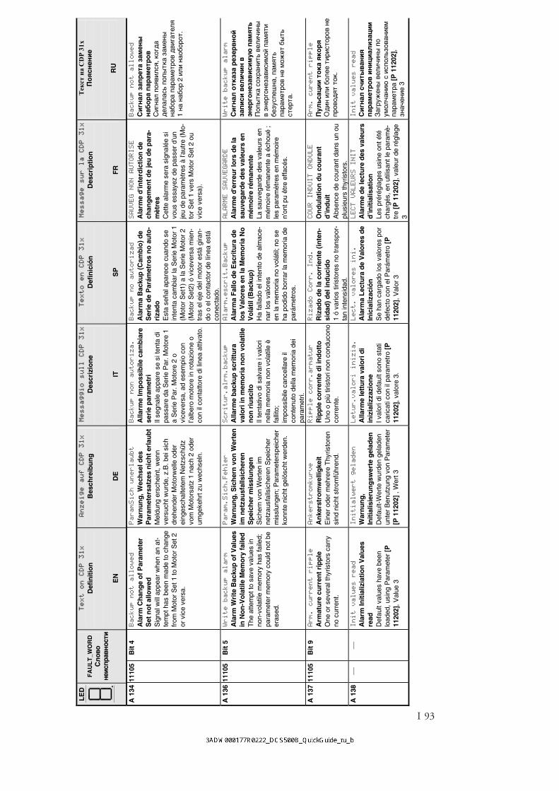
I 93
LE
D
FA
UL
T_W
OR
D
Сл
ов
о
неи
спр
авн
ост
и
Text on CDP 31x
Def
init
ion
EN
Anzeige auf CDP 31x
Bes
chre
ibu
ng
DE
Messaggio sull CDP 31x
Des
criz
ion
e
IT
Texto en CDP 31x
Def
inic
ión
SP
Message sur la CDP 31x
Des
crip
tio
n
FR
CD
P 3
1x
По
ясн
ени
е
RU
A 1
34 1
1105
Bit
4
Backup not allowed
Ala
rm C
han
ge
of
Par
amet
er
Set
no
t al
low
ed
Sig
nal w
ill a
ppea
r w
hen
an a
t-te
mpt
has
bee
n m
ade
to c
hang
e fr
om M
otor
Set
1 to
Mot
or S
et 2
or
vic
e ve
rsa.
ParamSich unerlaubt
War
nu
ng
, Wec
hse
l des
P
aram
eter
satz
es n
ich
t er
lau
bt
Mel
dung
ers
chei
nt, w
enn
vers
ucht
wur
de, z
.B. b
ei s
ich
dreh
ende
r M
otor
wel
le o
der
eing
esch
alte
tem
Net
zsch
ütz
vom
Mot
orsa
tz 1
nac
h 2
oder
um
geke
hrt z
u w
echs
eln.
Backup non autoriza.
Alla
rme
Imp
oss
ibile
cam
bia
re
seri
e p
aram
etri
Il
segn
ale
appa
re s
e si
tent
a di
pa
ssar
e da
Ser
ie P
ar. M
otor
e 1
a S
erie
Par
. Mot
ore
2 o
vice
vers
a, a
d es
empi
o co
n l’a
lber
o m
otor
e in
rot
azio
ne o
co
n il
cont
atto
re d
i lin
ea a
ttiva
to.
Backup no autorizad
Ala
rma
Bac
kup
(C
amb
io)
de
Ser
ie d
e P
arám
etro
s n
o a
uto
-ri
zad
o
Est
a se
ñal a
pare
ce c
uand
o se
in
tent
a ca
mbi
ar la
Ser
ie M
otor
1
(Mot
or S
et1)
a la
Ser
ie M
otor
2
(Mot
or S
et2)
ó v
icev
ersa
mie
n-tr
as e
l eje
del
mot
or e
stá
gira
n-do
o e
l con
tact
or d
e lín
ea e
stá
cone
ctad
o.
SAUVEG NON AUTORISE
Ala
rme
d'in
terd
icti
on
de
chan
gem
ent
de
jeu
de
par
a-m
ètre
s C
ette
ala
rme
sera
sig
nalé
e si
vo
us e
ssay
ez d
e pa
sser
d'u
n je
u de
par
amèt
res
à l'a
utre
(M
o-to
r S
et 1
ver
s M
otor
Set
2 o
u vi
ce v
ersa
).
Backup not allowed
Си
гнал
зап
рет
а за
мен
ы
наб
ор
а п
арам
етр
ов
С
игна
л п
ояви
лся
, ког
да
дел
алас
ь по
пытк
а за
мен
ы
набо
ра п
арам
етро
в д
вига
тел
я 1
на н
абор
2 и
ли
наоб
орот
.
A 1
36 1
1105
Bit
5
Write backup alarm
Ala
rm W
rite
Bac
kup
of
Val
ues
in
No
n-V
ola
tile
Mem
ory
fai
led
T
he a
ttem
pt to
sav
e va
lues
in
non-
vola
tile
mem
ory
has
faile
d;
para
met
er m
emor
y co
uld
not b
e er
ased
.
Param.Sich.Fehler
War
nu
ng
, Sic
her
n v
on
Wer
ten
im
net
zau
sfal
lsic
her
en
Sp
eich
er m
issl
un
gen
S
iche
rn v
on W
erte
n im
ne
tzau
sfal
lsic
here
n S
peic
her
mis
slun
gen;
Par
amet
ersp
eich
er
konn
te n
icht
gel
ösch
t wer
den.
Scritur.alrm.backup
Alla
rme
bac
kup
scr
ittu
ra
valo
ri in
mem
ori
a n
on
vo
lati
le
no
n r
iusc
ito
Il
tent
ativ
o di
sal
vare
i va
lori
nella
mem
oria
non
vol
atile
è
falli
to;
impo
ssib
ile c
ance
llare
il
cont
enut
o de
lla m
emor
ia d
ei
para
met
ri.
Alarm.escrit.Backup
Ala
rma
Fal
lo d
e E
scri
tura
de
los
Val
ore
s en
la M
emo
ria
No
V
olá
til (
Bac
kup
) H
a fa
llado
el i
nten
to d
e al
mac
e-na
r lo
s va
lore
s
en la
mem
oria
no
volá
til; n
o se
ha
pod
ido
borr
ar la
mem
oria
de
pará
met
ros.
ALARME SAUVEGARDE
Ala
rme
d'e
rreu
r lo
rs d
e la
sa
uve
gar
de
des
val
eurs
en
m
émo
ire
rém
anen
te
La s
auve
gard
e de
s va
leur
s en
m
émoi
re r
éman
ente
a é
chou
é ;
les
para
mèt
res
en m
émoi
re
n'on
t pu
être
effa
cés.
Write backup alarm
Си
гнал
отк
аза
рез
ерв
но
й
зап
иси
вел
ичи
н в
эн
ерго
нез
ави
сим
ую п
амя
ть
Поп
ытк
а со
хран
ить
вел
ичин
ы
в эн
ерго
неза
виси
мой
пам
яти
безу
спеш
на, п
амят
ь па
рам
етро
в не
мож
ет б
ыть
ст
ерта
.
A 1
37 1
1105
Bit
9
Arm. current ripple
Arm
atu
re c
urr
ent
rip
ple
O
ne o
r se
vera
l thy
risto
rs c
arry
no
cur
rent
.
Ankerstromkurve
An
kers
tro
mw
ellig
keit
E
iner
ode
r m
ehre
re T
hyris
tore
n si
nd n
icht
str
omfü
hren
d.
Ripple corr.armatur
Rip
ple
co
rren
te d
i in
do
tto
Uno
o p
iù ti
risto
ri no
n co
nduc
ono
corr
ente
.
Rizado Corr. Ind.
Riz
ado
de
la c
orr
ien
te (
inte
n-
sid
ad)
del
ind
uci
do
1 ó
vario
s tir
isto
res
no tr
ansp
or-
tan
inte
nsid
ad.
COUR INDUIT ONDULE
On
du
lati
on
du
co
ura
nt
d’in
du
it
Abs
ence
de
cour
ant d
ans
un o
u pl
usie
urs
thyr
isto
rs.
Arm. curent ripple
Пул
ьса
ци
и т
ок
а я
ко
ря
О
дин
ил
и бо
лее
тир
исто
ров
не
пров
одят
ток
.
A 1
38
Init values read
Ala
rm In
itia
lizia
tio
n V
alu
es
read
D
efau
lt va
lues
hav
e be
en
load
ed, u
sing
Par
amet
er [
P11
202]
, Val
ue 3
Initialwert geladen
War
nu
ng
, In
itia
lisie
run
gsw
erte
gel
aden
D
efau
lt-W
erte
wur
den
gela
den
unte
r B
enut
zung
von
Par
amet
er
[P 1
1202
] , W
ert 3
Letur.valori inizia.
Alla
rme
lett
ura
val
ori
di
iniz
ializ
zazi
on
e I v
alor
i di d
efau
lt so
no s
tati
caric
ati c
on il
par
amet
ro [
P11
202]
, val
ore
3.
Lect. valores ini.
Ala
rma
Lec
tura
de
Val
ore
s d
e In
icia
lizac
ión
S
e ha
n ca
rgad
o lo
s va
lore
s po
r de
fect
o co
n el
Par
ámet
ro [
P11
202]
, Val
or 3
LECT VALEURS INIT
Ala
rme
de
lect
ure
des
val
eurs
d
’init
ialis
atio
n
Les
prér
égla
ges
usin
e on
t été
ch
argé
s, e
n ut
ilisa
nt le
par
amè-
tre
[P 1
1202
], v
aleu
r de
rég
lage
3
Init values read
Си
гнал
счи
тыв
ани
я
пар
амет
ро
в и
ни
ци
али
зац
ии
З
агру
жен
ы в
елич
ины
по
умол
чани
ю с
исп
ольз
ован
ием
па
рам
етра
[P
112
02],
зн
ачен
ие 3
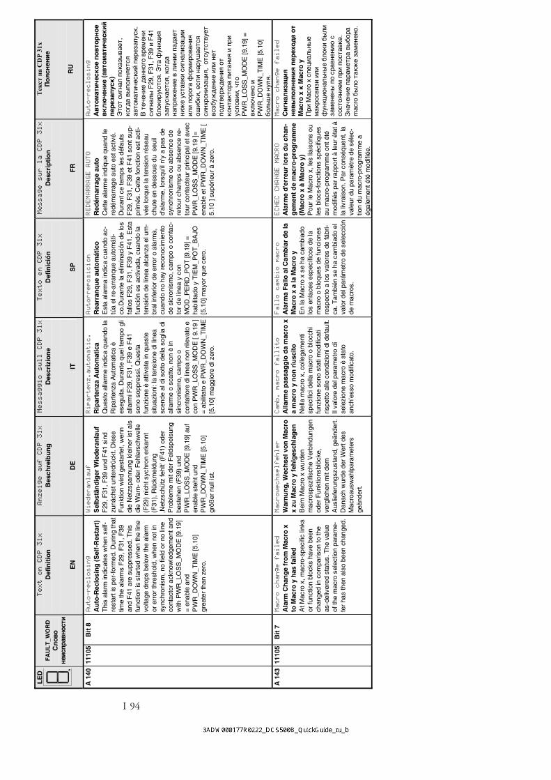
I 94
LE
D
FA
UL
T_W
OR
D
Сл
ов
о
неи
спр
авн
ост
и
Text on CDP 31x
Def
init
ion
EN
Anzeige auf CDP 31x
Bes
chre
ibu
ng
DE
Messaggio sull CDP 31x
Des
criz
ion
e
IT
Texto en CDP 31x
Def
inic
ión
SP
Message sur la CDP 31x
Des
crip
tio
n
FR
CD
P 3
1x
По
ясн
ени
е
RU
A 1
40
1110
5 B
it 8
Auto-reclosing
Au
to-R
eclo
sin
g (
Sel
f-R
esta
rt)
Thi
s al
arm
indi
cate
s w
hen
self-
rest
art i
s pe
r-fo
rmed
. Dur
ing
that
tim
e th
e al
arm
s F
29, F
31, F
39
and
F41
are
sup
pres
sed.
Thi
s fu
nctio
n is
sta
rted
whe
n th
e lin
e vo
ltage
dro
ps b
elow
the
alar
m
or e
rror
thre
shol
d, w
hen
not i
n sy
nchr
onis
m, n
o fie
ld o
r no
line
co
ntac
tor
ackn
owle
dgem
ent a
nd
with
PW
R_L
OS
S_M
OD
E [9
.19]
=
enab
le a
nd
PW
R_D
OW
N_T
IME
[5.1
0]
grea
ter
than
zer
o.
Wiederanlauf
Sel
bst
änd
iger
Wie
der
anla
uf
F29
, F31
, F39
und
F41
sin
d zu
näch
st u
nter
drüc
kt. D
iese
F
unkt
ion
wird
ges
tart
et, w
enn
die
Net
zspa
nnun
g kl
eine
r is
t als
di
e W
arn-
ode
r F
ehle
rsch
wel
le
(F29
) ni
cht s
ychr
on e
rkan
nt
(F31
), R
ückm
eldu
ng
‚Net
zsch
ütz
fehl
t’ (F
41)
oder
P
robl
eme
mit
der
Fel
dspe
isun
g be
steh
en (
F39
) un
d P
WR
_LO
SS
_MO
DE
[9.1
9] a
uf
enab
le s
teht
und
P
WR
_DO
WN
_TIM
E [5
.10]
gr
ößer
nul
l ist
.
Ripartenz.automatic.
Rip
arte
nza
Au
tom
atic
a
Que
sto
alla
rme
indi
ca q
uand
o la
R
ipar
tenz
a A
utom
atic
a è
eseg
uita
. Dur
ante
que
l tem
po g
li al
larm
i F29
, F31
, F39
e F
41
sono
sop
pres
si. Q
uest
a fu
nzio
ne è
atti
vata
in q
uest
e si
tuaz
ioni
: la
tens
ione
di l
inea
sc
ende
al d
i sot
to d
ella
sog
lia d
i al
larm
e o
scat
to, n
on è
in
sinc
roni
smo,
cam
po o
co
ntat
tore
di l
inea
non
rile
vato
e
con
PW
R_L
OS
S_M
OD
E [
9.19
] =
abili
tato
e P
WR
_DO
WN
_TIM
E
[5.1
0] m
aggi
ore
di z
ero.
Autorreposicion
Rea
rran
qu
e au
tom
átic
oE
sta
alar
ma
indi
ca c
uand
o ac
-tú
a el
re-
arra
nque
aut
omát
i-co
.Dur
ante
la e
limin
ació
n de
los
fallo
s F
29, F
31, F
39 y
F41
. Est
a fu
nció
n es
act
ivad
a, c
uand
o la
te
nsió
n de
líne
a al
canz
a el
um
-br
al in
ferio
r de
err
or o
ala
rma,
cu
ando
no
hay
reco
noci
mie
nto
de s
icro
nism
o, c
ampo
o c
onta
c-to
r de
líne
a y
con
MO
D_P
ER
D_P
OT
[9.1
9] =
ha
bilit
ado
y T
IEM
_PO
T_B
AJO
[5
.10]
may
or q
ue c
ero.
REDEMARRAGE AUTO
Red
émar
rag
e au
to
Cet
te a
larm
e in
diqu
e qu
and
le
redé
mar
rage
aut
o es
t act
ivé.
D
uran
t ce
tem
ps le
s dé
faut
s F
29, F
31, F
39 e
t F41
son
t sup
-pr
imés
. Cet
te fo
nctio
n es
t act
i-vé
e lo
rque
la te
nsio
n ré
seau
ch
ute
en d
esso
us d
u s
euil
d'al
arm
e, lo
rsqu
'il n
'y a
pas
de
sync
hron
ism
e ou
abs
ence
de
reto
ur c
ham
ps o
u ab
senc
e re
-to
ur c
onta
cteu
r pr
inci
pal e
t ave
c
PW
R_L
OS
S_M
OD
E [9
.19
]=
enab
le e
t PW
R_D
OW
N_T
IME
[ 5.
10 ]
supé
rieur
à z
ero.
Auto-reclosing
Ав
том
ати
ческ
ое
по
вто
рн
ое
вк
лю
чен
ие
(ав
том
ати
ческ
ий
п
ерез
апус
к)
Это
т си
гнал
пок
азы
вает
, ко
гда
выпо
лня
ется
ав
том
атич
ески
й пе
реза
пуск
. В
теч
ение
дан
ного
вре
мен
и си
гнал
ы F
29, F
31, F
39 и
F41
бл
окир
уютс
я. Э
та ф
ункц
ия
запу
скае
тся,
ког
да
напр
яжен
ие в
лин
ии п
адае
т ни
же
уста
вки
сигн
ализ
ации
ил
и по
рога
фор
мир
ован
ия
ошиб
ки, е
сли
нару
шае
тся
синх
рони
заци
я, о
тсут
ству
ет
возб
ужд
ение
ил
и не
т по
дтв
ерж
ден
ия о
т ко
нтак
тора
пит
ания
и п
ри
усл
овии
, что
P
WR
_LO
SS
_MO
DE
[9.1
9] =
вк
лю
чено
и
PW
R_D
OW
N_T
IME
[5.1
0]
бол
ьше
нул
я.
A 1
43
1110
5B
it 7
Macro change failed
Ala
rm C
han
ge
fro
m M
acro
x
to M
acro
y h
as f
aile
d
At M
acro
x, m
acro
-spe
cific
link
s or
func
tion
bloc
ks h
ave
been
chan
ged
in c
ompa
rison
to th
e as
-del
iver
ed s
tatu
s. T
he v
alue
of
the
mac
ro s
elec
tion
para
me-
ter
has
then
als
o be
en c
hang
ed.
Macrowechselfehler
War
nu
ng
, Wec
hse
l vo
n M
acro
x
zu M
acro
y f
ehlg
esch
lag
en
Bei
m M
acro
x w
urde
n m
acro
spez
ifisc
he V
erbi
ndun
gen
oder
Fun
ktio
nsbl
öcke
, ve
rglic
hen
mit
dem
A
uslie
feru
ngsz
usta
nd, g
eänd
ert.
Dan
ach
wur
de d
er W
ert d
es
Mac
roau
swah
lpar
amet
ers
geän
dert
.
Camb. macro fallito
Alla
rme
pas
sag
gio
da
mac
ro x
a
mac
ro y
no
n r
iusc
ito
N
ella
mac
ro x
, col
lega
men
ti sp
ecifi
ci d
ella
mac
ro o
blo
cchi
fu
nzio
ne s
ono
stat
i mod
ifica
ti ris
petto
alle
con
dizi
oni d
i def
ault.
Il
valo
re d
el p
aram
etro
di
sele
zion
e m
acro
è s
tato
an
ch’e
sso
mod
ifica
to.
Fallo cambio macro
Ala
rma
Fal
lo a
l Cam
bia
r d
e la
M
acro
x a
la M
acro
y
En
la M
acro
x s
e ha
cam
biad
o lo
s en
lace
s es
pecí
ficos
de
la
mac
ro o
blo
ques
de
func
ione
s re
spec
to a
los
valo
res
de fá
bri-
ca. T
ambi
én s
e ha
cam
biad
o el
va
lor
del p
arám
etro
de
sele
cció
n de
mac
ros.
ECHEC CHANGE MACRO
Ala
rme
d'e
rreu
r lo
rs d
u c
han
-g
emen
t d
e m
acro
-pro
gra
mm
e (M
acro
x à
Mac
ro y
) P
our
le M
acro
x, l
es li
aiso
ns o
u le
s bl
ocs-
fonc
tions
spé
cifiq
ues
au m
acro
-pro
gram
me
ont é
té
mod
ifiés
par
rap
port
à le
ur é
tat à
la
livr
aiso
n. P
ar c
onsé
quen
t, la
va
leur
du
para
mèt
re d
e sé
lec-
tion
du m
acro
-pro
gram
me
a ég
alem
ent é
té m
odifi
ée.
Macro change failed
Си
гнал
иза
ци
я
нев
ып
ол
нен
ия
пер
ехо
да
от
Mac
ro x
к M
acro
y
При
Mac
ro x
спе
циал
ьны
е м
акро
связ
и ил
и ф
ункц
иона
льн
ые
блок
и бы
ли
зам
енен
ы п
о ср
авне
нию
с
сост
ояни
ем п
ри п
оста
вке.
З
наче
ние
пара
мет
ра в
ыбо
ра
mac
ro б
ыл
о та
кже
зам
енен
о.
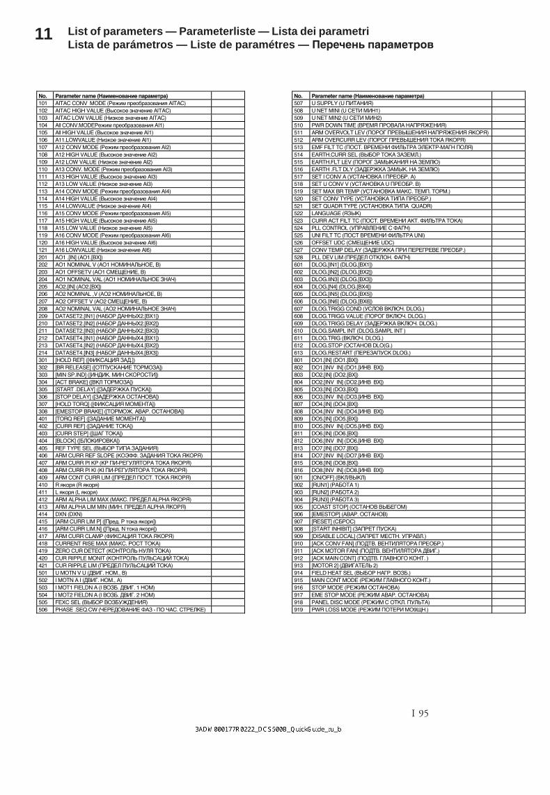
I 95
List of parameters — Parameterliste — Lista dei parametriLista de parámetros — Liste de paramétres — Перечень параметров
11
No. Parameter name (Наименование параметра) 101 AITAC CONV MODE (Режим преобразования AITAC) 102 AITAC HIGH VALUE (Высокое значение AITAC) 103 AITAC LOW VALUE (Низкое значение AITAC) 104 All CONV.MODEРежим преобразования AI1) 105 All HIGH VALUE (Высокое значение AI1) 106 A11.LOWVALUE (Низкое значение AI1) 107 A12 CONV MODE (Режим преобразования AI2) 108 A12 HIGH VALUE (Высокое значение AI2) 109 A12 LOW VALUE (Низкое значение AI2) 110 A13 CONV. MODE (Режим преобразования AI3) 111 A13 HIGH VALUE (Высокое значение AI3) 112 A13 LOW VALUE (Низкое значение AI3) 113 A14 CONV MODE (Режим преобразования AI4) 114 A14 HIGH VALUE (Высокое значение AI4) 115 A14 LOWVALUE (Низкое значение AI4) 116 A15 CONV MODE (Режим преобразования AI5) 117 A15 HIGH VALUE (Высокое значение AI5) 118 A15 LOW VALUE (Низкое значение AI5) 119 A16 CONV MODE (Режим преобразования AI6) 120 A16 HIGH VALUE (Высокое значение AI6) 121 A16 LOWVALUE (Низкое значение AI6) 201 AО1 .[IN] (AО1.[ВХ]) 202 AО1 NOMINAL V (AО1 НОМИНАЛЬНОЕ, В) 203 AО1 OFFSETV (AО1 СМЕЩЕНИЕ, В) 204 AО1 NOMINAL VAL (AО1 НОМИНАЛЬНОЕ ЗНАЧ) 205 AО2.[IN] (AО2.[ВХ]) 206 AО2 NOMINAL ,V (AО2 НОМИНАЛЬНОЕ, В) 207 AО2 OFFSET V (AО2 СМЕЩЕНИЕ, В) 208 AО2 NOMINAL VAL (AО2 НОМИНАЛЬНОЕ ЗНАЧ) 209 DATASET2.[IN1] (НАБОР ДАННЫХ2.[ВХ1]) 210 DATASET2.[IN2] (НАБОР ДАННЫХ2.[ВХ2]) 211 DATASET2.[IN3] (НАБОР ДАННЫХ2.[ВХ3]) 212 DATASET4.[IN1] (НАБОР ДАННЫХ4.[ВХ1]) 213 DATASET4.[IN2] (НАБОР ДАННЫХ4.[ВХ2]) 214 DATASET4.[lN3] (НАБОР ДАННЫХ4.[ВХ3]) 301 [HOLD REF] ([ФИКСАЦИЯ ЗАД.]) 302 [BR RELEASE] ([ОТПУСКАНИЕ ТОРМОЗА]) 303 [MIN SP.IND] ([ИНДИК. МИН СКОРОСТИ]) 304 [ACT BRAKE] ([ВКЛ ТОРМОЗА]) 305 [START .DELAY] ([ЗАДЕРЖКА ПУСКА]) 306 [STOP DELAY] ([ЗАДЕРЖКА ОСТАНОВА]) 307 [HOLD TORQ] ([ФИКСАЦИЯ МОМЕНТА]) 308 [EMESTOP BRAKE] ([ТОРМОЖ. АВАР. ОСТАНОВА]) 401 [TORQ REF] ([ЗАДАНИЕ МОМЕНТА]) 402 [CURR REF] ([ЗАДАНИЕ ТОКА]) 403 [CURR STEP] ([ШАГ ТОКА]) 404 [BLOCK] ([БЛОКИРОВКА]) 405 REF TYPE SEL (ВЫБОР ТИПА ЗАДАНИЯ) 406 ARM CURR REF SLOPE (КОЭФФ. ЗАДАНИЯ ТОКА ЯКОРЯ) 407 ARM CURR PI KP (KP ПИ-РЕГУЛЯТОРА ТОКА ЯКОРЯ) 408 ARM CURR PI KI (KI ПИ-РЕГУЛЯТОРА ТОКА ЯКОРЯ) 409 ARM CONT CURR LIM ([ПРЕДЕЛ ПОСТ. ТОКА ЯКОРЯ) 410 R якоря (R якоря) 411 L якоря (L якоря) 412 ARM ALPHA LIM MAX (МАКС. ПРЕДЕЛ ALPHA ЯКОРЯ) 413 ARM ALPHA LIM MIN (МИН. ПРЕДЕЛ ALPHA ЯКОРЯ) 414 DXN (DXN) 415 [ARM CURR LIM P] ([Пред. Р тока якоря]) 416 [ARM CURR LIM.N] ([Пред. N тока якоря]) 417 ARM CURR CLAMP (ФИКСАЦИЯ ТОКА ЯКОРЯ) 418 CURRENT RISE MAX (МАКС. РОСТ ТОКА) 419 ZERO CUR DETECT (КОНТРОЛЬ НУЛЯ ТОКА) 420 CUR RIPPLE MONIT (КОНТРОЛЬ ПУЛЬСАЦИЙ ТОКА) 421 CUR RIPPLE LIM (ПРЕДЕЛ ПУЛЬСАЦИЙ ТОКА) 501 U MOTN V U (ДВИГ. НОМ., В) 502 I MOTN A I (ДВИГ. НОМ., А) 503 I MOT1 FIELDN A (I ВОЗБ. ДВИГ. 1 НОМ) 504 I MOT2 FIELDN A (I ВОЗБ. ДВИГ. 2 НОМ) 505 FEXC SEL (ВЫБОР ВОЗБУЖДЕНИЯ) 506 PHASE .SEQ.CW (ЧЕРЕДОВАНИЕ ФАЗ - ПО ЧАС. СТРЕЛКЕ)
No. Parameter name (Наименование параметра) 507 U SUPPLY (U ПИТАНИЯ) 508 U NET MINI (U СЕТИ МИН1) 509 U NET MIN2 (U СЕТИ МИН2) 510 PWR DOWN TIME (ВРЕМЯ ПРОВАЛА НАПРЯЖЕНИЯ) 511 ARM OVERVOLT LEV (ПОРОГ ПРЕВЫШЕНИЯ НАПРЯЖЕНИЯ ЯКОРЯ) 512 ARM OVERCURR LEV (ПОРОГ ПРЕВЫШЕНИЯ ТОКА ЯКОРЯ) 513 EMF FILT TC (ПОСТ. ВРЕМЕНИ ФИЛЬТРА ЭЛЕКТР-МАГН ПОЛЯ) 514 EARTH.CURR SEL (ВЫБОР ТОКА ЗАЗЕМЛ.) 515 EARTH.FLT LEV (ПОРОГ ЗАМЫКАНИЯ НА ЗЕМЛЮ) 516 EARTH .FLT DLY (ЗАДЕРЖКА ЗАМЫК. НА ЗЕМЛЮ) 517 SET I CONV A (УСТАНОВКА I ПРЕОБР. А) 518 SET U CONV V (УСТАНОВКА U ПРЕОБР. В) 519 SET MAX BR TEMP (УСТАНОВКА МАКС. ТЕМП. ТОРМ.) 520 SET CONV TYPE (УСТАНОВКА ТИПА ПРЕОБР.) 521 SET QUADR TYPE (УСТАНОВКА ТИПА QUADR) 522 LANGUAGE (ЯЗЫК) 523 CURR ACT FILT TC (ПОСТ. ВРЕМЕНИ АКТ. ФИЛЬТРА ТОКА) 524 PLL CONTROL (УПРАВЛЕНИЕ С ФАПЧ) 525 UNI FILT TC (ПОСТ ВРЕМЕНИ ФИЛЬТРА UNI) 526 OFFSET UDC (СМЕЩЕНИЕ UDC) 527 CONV TEMP DELAY (ЗАДЕРЖКА ПРИ ПЕРЕГРЕВЕ ПРЕОБР.) 528 PLL DEV LIM (ПРЕДЕЛ ОТКЛОН. ФАПЧ) 601 DLOG.[IN1] (DLOG.[ВХ1]) 602 DLOG.[IN2] (DLOG.[ВХ2]) 603 DLOG.IIN3] (DLOG.[ВХ3]) 604 DLOG.[N4] (DLOG.[ВХ4]) 605 DLOG.[IN5] (DLOG.[ВХ5]) 606 DLOG.[IN6] (DLOG.[ВХ6]) 607 DLOG.TRIGG COND (УСЛОВ ВКЛЮЧ. DLOG.) 608 DLOG.TRIGG VALUE (ПОРОГ ВКЛЮЧ. DLOG.) 609 DLOG.TRIGG DELAY (ЗАДЕРЖКА ВКЛЮЧ. DLOG.) 610 DLOG.SAMPL INT (DLOG.SAMPL INT ) 611 DLOG.TRIG (ВКЛЮЧ. DLOG.) 612 DLOG.STOP (ОСТАНОВ DLO(G.) 613 DLOG.RESTART (ПЕРЕЗАПУСК DLOG.) 801 DO1.[IN] (DO1.[ВХ]) 802 DO1.[INV IN] (DO1.[ИНВ ВХ]) 803 DO2.[IN] (DO2.[ВХ]) 804 DO2.[INV IN] (DO2.[ИНВ ВХ]) 805 DO3.[IN] (DO3.[ВХ]) 806 DO3.[INV IN] (DO3.[ИНВ ВХ]) 807 DO4.[IN] (DO4.[ВХ]) 808 DO4.[INV IN] (DO4.[ИНВ ВХ]) 809 DO5.[IN] (DO5.[ВХ]) 810 DO5.[INV IN] (DO5.[ИНВ ВХ]) 811 DO6.[IN] (DO6.[ВХ]) 812 DO6.[INV IN] (DO6.[ИНВ ВХ]) 813 DO7.[IN] (DO7.[ВХ]) 814 DO7.[INV IN] (DO7.[ИНВ ВХ]) 815 DO8.[IN] (DO8.[ВХ]) 816 DO8.[INV IN] (DO8.[ИНВ ВХ]) 901 [ON/OFF] (ВКЛ/ВЫКЛ) 902 [RUN1] (РАБОТА 1) 903 [RUN2] (РАБОТА 2) 904 [RUN3] (РАБОТА 3) 905 [COAST STOP] (ОСТАНОВ ВЫБЕГОМ) 906 [EMESTOP] (АВАР. ОСТАНОВ) 907 [RESET] (СБРОС) 908 [START INHIBIT] (ЗАПРЕТ ПУСКА) 909 [DISABLE LOCAL] (ЗАПРЕТ МЕСТН. УПРАВЛ.) 910 [ACK CONV FAN] (ПОДТВ. ВЕНТИЛЯТОРА ПРЕОБР.) 911 [ACK MOTOR FAN] (ПОДТВ. ВЕНТИЛЯТОРА ДВИГ.) 912 [ACK MAIN CONT] (ПОДТВ. ГЛАВНОГО КОНТ. ) 913 [MOTOR 2] (ДВИГАТЕЛЬ 2) 914 FIELD HEAT SEL (ВЫБОР НАГР. ВОЗБ.) 915 MAIN CONT MODE (РЕЖИМ ГЛАВНОГО КОНТ.) 916 STOP MODE (РЕЖИМ ОСТАНОВА) 917 EME STOP MODE (РЕЖИМ АВАР. ОСТАНОВА) 918 PANEL DISC MODE (РЕЖИМ С ОТКЛ. ПУЛЬТА) 919 PWR LOSS MODE (РЕЖИМ ПОТЕРИ МО9ЩН.)
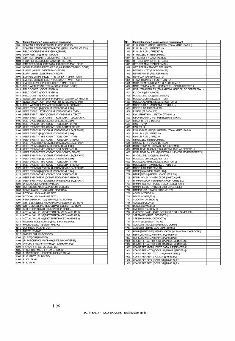
I 96
No. Parameter name (Наименование параметра) 920 COMFAULT MODE (РЕЖИМ НЕИСПР. СВЯЗИ) 921 COMFAULT TIMEOUT(ВРЕМЯ ОЖИД ПРИ НЕИСПР. СВЯЗИ) 1001 FIELD MODE (РЕЖИМ ВОЗБУЖДЕНИЯ) 1002 [FLUX REF] (ЗАДАНИЕ ПОТОКА) 1003 [EMF REF] (ЗАДАНИЕ ЭЛЕКТР-МАГН ПОЛЯ ) 1004 [FLUX REF SEL] (ВЫБОР ЗАДАН ИЯ ПОТОКА) 1005 [EMF REF SEL] (ВЫБОР ЗАДАНИЯ ЭЛЕКТР-МАГН ПОЛЯ) 1006 LOCAL EMF REF (МЕСТНОЕ ЗАДАНИЕ ЭЛЕКТР-МАГН ПОЛЯ) 1007 EMF KP (КР РЕГ. ЭЛЕКТР-МАГН ПОЛЯ) 1008 EMF Kl (КI РЕГ. ЭЛЕКТР-МАГН ПОЛЯ) 1009 EMF REG LIM P (ПРЕДЕЛ Р РЕГ. ЭЛЕКТР-МАГН ПОЛЯ) 1010 EMF REG LIM N (ПРЕДЕЛ N РЕГ. ЭЛЕКТР-МАГН ПОЛЯ) 1011 EMF REL LEV (ПОРОГ REL ЭЛЕКТР-МАГН ПОЛЯ) 1012 FIELD WEAK POINT (ТОЧКА ОСЛАБЛЕНИЯ ПОЛЯ) 1013 FIELD CONST 1 (ПОСТ. ВОЗБ. 1) 1014 FIELD CONST 2 (ПОСТ. ВОЗБ. 2) 1015 FIELD CONST 3 (ПОСТ. ВОЗБ. 3) 1016 GENER.EMF REF (ФОРМИР ЗАДАНИЯ ЭЛЕКТР-МАГН ПОЛЯ) 1017 GENER.WEAK POINT (ФОРМИР ТОЧКИ ОСЛАБЛЕНИЯ ) 1018 FIELD WEAK DELAY (ЗАДЕРЖКА ОСЛАБЛ. ВОЗБУЖД.) 1101 USER EVENT1.[IN] (СОБЫТ. ПОЛЬЗОВАТ.1.[ВХ]) 1102 USER EVENT1 .TYPE (СОБЫТ. ПОЛЬЗОВАТ.1 .ТИП) 1103 USER EVENT1 .TEXT (СОБЫТ. ПОЛЬЗОВАТ.1 .ТЕКСТ) 1104 USER EVENT1 .DLY (СОБЫТ. ПОЛЬЗОВАТ.1 .ЗАДЕРЖКА) 1105 USER EVENT2.[IN] (СОБЫТ. ПОЛЬЗОВАТ.2.[ВХ]) 1106 USER EVENT2 TYPE (СОБЫТ. ПОЛЬЗОВАТ.2 ТИП) 1107 USER EVENT2.TEXT (СОБЫТ. ПОЛЬЗОВАТ.2.ТЕКСТ) 1108 USER EVENT2.DLY (СОБЫТ. ПОЛЬЗОВАТ.2.ЗАДЕРЖКА) 1109 USER EVENT3.[IN] (СОБЫТ. ПОЛЬЗОВАТ.3.[ВХ]) 1110 USER EVENT3.TYPE (СОБЫТ. ПОЛЬЗОВАТ.3.ТИП) 1111 USER EVENT3 TEXT (СОБЫТ. ПОЛЬЗОВАТ.3 ТЕКСТ) 1112 USER EVENT3.DLY (СОБЫТ. ПОЛЬЗОВАТ.3.ЗАДЕРЖКА) 1113 USER EVENT4.[IN] (СОБЫТ. ПОЛЬЗОВАТ.4.[ВХ]) 1114 USER EVENT4.TYPE (СОБЫТ. ПОЛЬЗОВАТ.4.ТИП) 1115 USER EVENT4.TEXT (СОБЫТ. ПОЛЬЗОВАТ.4.ТЕКСТ) 1116 USER EVENT4.DLY (СОБЫТ. ПОЛЬЗОВАТ.4.ЗАДЕРЖКА) 1117 USER EVENT5.[IN] (СОБЫТ. ПОЛЬЗОВАТ.5.[ВХ]) 1118 USER EVENT5 TYPE (СОБЫТ. ПОЛЬЗОВАТ.5 ТИП) 1119 USER EVENT5.TEXT (СОБЫТ. ПОЛЬЗОВАТ.5.ТЕКСТ) 1120 USER EVENT5.DLY (СОБЫТ. ПОЛЬЗОВАТ.5.ЗАДЕРЖКА) 1121 USER EVENT6 [IN] (СОБЫТ. ПОЛЬЗОВАТ.6 [ВХ]) 1122 USER EVENT6.TYPE (СОБЫТ. ПОЛЬЗОВАТ.6 ТИП) 1123 USER EVENT6TEXT (СОБЫТ. ПОЛЬЗОВАТ.6ТЕКСТ) 1124 USER EVENT6.DLY (СОБЫТ. ПОЛЬЗОВАТ.6 ЗАДЕРЖКА) 1201 DRIVEMODE (РЕЖИМ ПРИВОДА) 1202 CMT DCS500 ADDR (АДРЕС CMT DCS500 ) 1203 DRIVE ID (ИДЕНТИФИКАТОР ПРИВОДА) 1204 POT1 VALUE (ЗНАЧЕНИЕ ПОТ.1) 1205 POT2 VALUE (ЗНАЧЕНИЕ ПОТ.2) 1206 PERIOD BTW.POT1/2 (ПЕРИОД BTW. ПОТ1/2) 1207 WRITE ENABLE KEY (КНОПКА РАЗРЕШЕНИЯ ЗАПИСИ) 1208 WRITE ENABLE PIN (ВЫВОД РАЗРЕШЕНИЯ ЗАПИСИ) 1209 SELECT OPER.SYST (ВЫБОР ОПЕР. СИСТ.) 1210 ACTUAL VALUE 1 (ДЕЙСТВИТЕЛЬНОЕ ЗНАЧЕНИЕ 1) 1211 ACTUAL VALUE 2 (ДЕЙСТВИТЕЛЬНОЕ ЗНАЧЕНИЕ 2) 1212 ACTUAL VALUE 3 (ДЕЙСТВИТЕЛЬНОЕ ЗНАЧЕНИЕ 3) 1213 FELDBUS NODE ADDR (АДРЕС УЗЛА FELDBUS) 1214 MACRO SELECT (ВЫБОР МАКРО) 1215 DCF MODE (РЕЖИМ DCF) 1216 D1/OVP (D1/OVP) 1217 OVP SELECT (ВЫБОР OVP) 1301 [F1 REF] (ЗАДАНИЕ F1) 1302 [F1 FORCE FWD] (F1 ПРИНУДИТЕЛЬНО ВПЕРЕД) 1303 [F1FORCE REV] (F1 ПРИНУДИТЕЛЬНО НАЗАД) 1304 [F1.ACK] (F1 ПОДТВЕРЖДЕНИЕ) 1305 F1 CURR GT MIN L (F1 ТОК GT МИН L) 1306 F1 OVERCURR L (F1 ПРЕВЫШЕНИЕ ТОКА L) 1307 F1 CURR TC (F1 ТОК TC) 1308 F1 KP (F1 KP) 1309 F1 Kl (F1 Kl)
No. Parameter name (Наименование параметров) 1310 F1 U AC DIFF MAX (F1 U ПЕРЕМ. ТОКА МАКС. РАЗН. ) 1311 F1 U LIM N (F1 U ПРЕДЕЛ N ) 1312 F1 U LIM P (F1 U ПРЕДЕЛ Р) 1313 F1 RED.SEL (F1 ВЫБОР RED.) 1314 FI RED.REF (F1 ЗАДАНИЕ RED.) 1315 OPTI.REF GAIN (OPTI.REF GAIN) 1316 OPTI.REF MINL (OPTI.REF MINL) 1317 OPTI.REF MIN TD (OPTI.REF MIN TD) 1318 REV.REV HYST (REV.REV HYST) 1319 REV.REF HYST (REV.REF HYST) 1320 REV.FLUX TD (REV.FLUX TD) 1321 F1 CURR MIN TD (F1 CURR MIN TD) 1401 MOT1. [TEMP IN] (ДВИГАТЕЛЬ1. [ВХ ТЕМП.]) 1402 MOT1 .TEMP ALARM L (ДВИГАТЕЛЬ1 .СИГНАЛ ПЕРЕГР. L) 1403 MOT1 .TEMP FAULT L (ДВИГАТЕЛЬ1 .НЕИСПР. ПО ПЕРЕГРЕВУ L) 1404 KLIXON IN] (ВХ KLIXON ) 1405 MODEL1.SEL (МОДЕЛЬ1.ВЫБОР) 1406 MODEL1.CURR (МОДЕЛЬ1.ТОК) 1407 MODEL1.ALARM L (МОДЕЛЬ1.СИГНАЛ L) 1408 MODEL1.TRIP L (МОДЕЛЬ1.ОТКЛЮЧ. L) 1409 MODEL1.TC (МОДЕЛЬ1.TC) 1501 F2 REF] (F2 ЗАДАНИЕ) 1502 F2 CURR GT MIN L (F2 ТОК GT МИН. L) 1503 F2 OVERCURR L (F2 ПРЕВЫШЕНИЕ ТОКА L) 1504 F2 CURR TC (F2 ТОК TC) 1505 F2 KP (F2 KP) 1506 F2 Kl (F2 Kl) 1507 F2 U AC DIFF MAX (F2 U ПЕРЕМ. ТОКА МАКС. РАЗН.) 1508 F2 U LIM N (F2 U ПРЕД. N) 1509 F2 U LIM P (F2 U ПРЕД. P) 1510 F2 RED.SEL (F2 ВЫБОР RED.) 1511 F2 RED.REF (F2 ЗАДАНИЕ RED.) 1601 MOT2.[TEMPI N] (ДВИГАТЕЛЬ2. [ВХ ТЕМП.]) 1602 MOT2.TEMP ALARM L (ДВИГАТЕЛЬ2 .СИГНАЛ ПЕРЕГР. L) 1603 MOT2.TEMP FAULT L (ДВИГАТЕЛЬ2 .НЕИСПР. ПО ПЕРЕГРЕВУ L) 1604 MODEL2.SEL (МОДЕЛЬ2.ВЫБОР) 1605 MODEL2.CURR (МОДЕЛЬ2.ТОК) 1606 MODEL2.ALARM L (МОДЕЛЬ2.СИГНАЛ L) 1607 MODEL2.TRIP L (МОДЕЛЬ2.ОТКЛЮЧ. L) 1608 MODEL2.TC (МОДЕЛЬ2.TC) 1701 RAMP.[IN] (ИЗМЕН. СКОР. [ВХ]) 1702 RAMP.[RES IN] (ИЗМЕН. СКОР. [РЕЗ. ВХ]) 1703 RAMP. [HOLD] (ИЗМЕН. СКОР. [ФИКСАЦИЯ]) 1704 RAMP.[FOLLOW IN] (ИЗМЕН. СКОР. [СЛЕД. ВХ]) 1705 RAMP.[FOLL ACT] (ИЗМЕН. СКОР. [СЛЕД. АКТ]) 1706 RAMP.[RES OUT] (ИЗМЕН. СКОР. [РЕЗ. ВЫХ]) 1707 RAMP.(T1/T2] (ИЗМЕН. СКОР. (T1/T2]) 1708 ACCEL1 (УСКОР.1) 1709 DECEL1 (ЗАМЕДЛ.1) 1710 SMOOTH1 (РАВНОМ.1) 1711 ACCEL2 (УСКОР.2) 1712 DECEL2 (ЗАМЕДЛ.2) 1713 SMOOTH2 (РАВНОМ.2) 1714 EMESTOP RAMP (АВАР. ОСТАНОВ С ЛИН. ЗАМЕДЛЕН.) 1715 SPEEDMAX (МАКС. СКОРОСТЬ) 1716 SPEEDMIN (МИН. СКОРОСТЬ) 1717 STARTSEL (ВЫБОР ПУСКА) 1718 ACC COMP.MODE (РЕЖИМ ACC COMP.) 1719 ACC COMP.TRMIN (ACC COMP.TRMIN)
1720 RAMP.[SPEED SET] (ИЗМЕН. СКОР. [УСТАНОВКА СКОРОСТИ]) 1801 REF SUM.[IN1] (СУММАРН. ЗАДАН.[ВХ1]) 1802 REF SUM.[IN2] (СУММАРН. ЗАДАН.[ВХ2]) 1901 CONST REF.[ACT1] (ПОСТ. ЗАДАНИЕ.[ДЕЙСТВ.1]) 1902 CONST REF.[ACT2] (ПОСТ. ЗАДАНИЕ.[ДЕЙСТВ.2]) 1903 CONST REF.[IACT3] (ПОСТ. ЗАДАНИЕ.[ДЕЙСТВ.3]) 1904 CONST.REF.[ACT4] (ПОСТ. ЗАДАНИЕ.[ДЕЙСТВ.4]) 1905 CONST REF.DEF (ПОСТ. ЗАДАНИЕ.ОПРЕД) 1906 CONST REF.REF1 (ПОСТ. ЗАДАНИЕ.ЗАД.1)
1907 CONST REF.REF2 (ПОСТ. ЗАДАНИЕ.ЗАД.2) 1908 CONST REF.REF3 (ПОСТ. ЗАДАНИЕ.ЗАД.3)
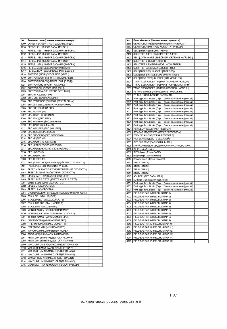
I 97
No. Parameter name (Наименование параметра)
1909 CONST REF.REF4 (ПОСТ. ЗАДАНИЕ. ЗАД.4)
1910 REFSEL.[IN1] (ВЫБОР ЗАДАНИЯ [ВХ1])
1911 REFSEL.[SEL1] (ВЫБОР ЗАДАНИЯ [ВЫБОР1])
1912 REFSEL.[IN2] (ВЫБОР ЗАДАНИЯ [ВХ2])
1913 REFSEL.[SEL2] (ВЫБОР ЗАДАНИЯ [ВЫБОР2])
1914 REFSEL.[IN3] (ВЫБОР ЗАДАНИЯ [ВХ3])
1915 REFSEL.[SEL3] (ВЫБОР ЗАДАНИЯ [ВЫБОР3])
1916 REFSEL.[ADD] (ВЫБОР ЗАДАНИЯ [ДОП.]) 1917 REFSEL.[REV] (ВЫБОР ЗАДАНИЯ [РЕВЕРС])
1918 SOFTPOT. [INCR] (ПРОГР. ПОТ. [УВЕЛ.])
1919 SOFTPOT.[DECR] (ПРОГР. ПОТ. [УМЕНЬШ.])
1920 SOFTPOT.[FOLLOW] (ПРОГР. ПОТ. [СЛЕД.])
1921 SOFTPOT.OHL (ПРОГР. ПОТ. [OHL.])
1922 SOFTPOT.OLL (ПРОГР. ПОТ. [OLL.]) 1923 SOFTPOT.[ENABLE] (ПРОГР. ПОТ. [ВКЛ.])
2001 ERR.[IN] (ОШИБКА [ВХ]) 2002 ERR.[STEP] (ОШИБКА [ШАГ])
2003 ERR.[WIN MODE] (ОШИБКА [РЕЖИМ ОКНА])
2004 ERR.WIN SIZE (ОШИБКА. РАЗМЕР ОКНА)
2005 ERR.FRS (ОШИБКА FRS)
2006 SPC.[IN] (SPC.[IN])
2007 SPC.[RINT1] (SPC.[RINT1)
2008 SPC.[IBAL] (SPC.IBAL]) 2009 SPC.[BALREF1] (SPC.[BALREF1)
2010 SPC.fBAL21 (SPC.fBAL21)
2011 SPC.[BAL2REF] (SPC.[BAL2REF])
2012 SPC.[HOLDI] (SPC.[HOLDI])
2013 SPC.DROOPING (SPC.DROOPING) 2014 SPC.KP (SPC.KP)
2015 SPC.KPSMIN (SPC.KPSMIN)
2016 SPC.KPSPOINT (SPC.KPSPOINT)
2017 SPC.KPSWEAKFILT (SPC.KPSWEAKFILT)
2018 SPC.KI (SPC.KI)
2019 SPC.TD (SPC.TD)
2020 SPC.TF (SPC.TF)
2021 ERR. [SPEED.ACT] (ОШИБКА [ДЕЙСТВИТ. СКОРОСТЬ])
2101 FACHOPULS NR (ЧИСЛО ИМПУЛЬСОВ
2102 SPEED MEAS MODE (РЕЖИМ ИЗМЕРЕНИЯ СКОРОСТИ) 2103 SPEED SCALING (МАСШТАБИР. СКОРОСТИ)
2104 SPEED .ACT. FTP (ДЕЙСТВ. СКОР. FTP)
2105 SPEED ACT FLT FTP (ДЕЙСТВ. СКОР. FLT FTP)
2201 MIN SPEED L (МИН. СКОРОСТЬ L) 2202 SPEED LI (СКОРОСТЬ L1)
2203 SPEED L2 (СКОРОСТЬ L2)
2204 OVERSPEEDLIMIT (ПРЕДЕЛ ПРЕВЫШЕНИЯ СКОРОСТИ)
2205 STALL.SEL (STALL.ВЫБОР)
2206 STALL.SPEED (STALL.СКОРОСТЬ)
2207 STALL.TORQUE (STALL.МОМЕНТ)
2208 STALL.TIME (STALL.ВРЕМЯ)
2209 MON.MEAS LEV (УРОВ.КОНТР.ИЗМЕР.)
2210 MON.EMF V (КОНТР. ЭЛЕКТР-МАГН ПОЛЯ V)
2301 [SPCTORQMAX] (МАКС МОМЕНТ SPC])
2302 [SPCTORQMIN] (МИН МОМЕНТ SPC])
2303 [TREFTORQMAX] (МАКС МОМЕНТ T])
2304 [TREFTORQ.MIN] (МИН МОМЕНТ T])
2305 TORQMAX (МАКСИМАЛЬНЫЙ МОМЕНТ)
2306 TORQ MIN (МИНИМАЛЬНЫЙ МОМЕНТ)
2307 ARM CURR LIM P (ПРЕДЕЛ ТОКА ЯКОРЯ Р) 2308 ARM CURR LIM N (ПРЕДЕЛ ТОКА ЯКОРЯ N)
2309 MAX CURR LIM SPD (МАКС. ПРЕДЕЛ ТОКА SPD)
2310 MAX CURRLIM N1 (МАКС. ПРЕДЕЛ ТОКА N1) 2311 MAX CURR LIM N2 (МАКС. ПРЕДЕЛ ТОКА N2)
2312 MAX CURR LIM N3 (МАКС. ПРЕДЕЛ ТОКА N3)
2313 MAXCURRLIM N4 (МАКС. ПРЕДЕЛ ТОКА N4)
2314 MAX CURR LIM N5 (МАКС. ПРЕДЕЛ ТОКА N5)
2315 GEAR.STARTTORQ (МОМЕНТ ПУСКА ПРИВОДА)
No. Parameter name (Наименование параметра)
2316 GEAR.TORQTIME (ВРЕМЯ МОМЕНТА ПРИВОДА) 2317 GEAR.TORQ RAMP (ИЗМ МОМЕНТА ПРИВОДА)
2401 SEL1.[TREFA] (ВЫБОР1.[TREFA])
2402 SEL1.TREF A..FTC (ВЫБОР1.TREF A..FTC)
2403 SEL1.[LOAD SHARE] (ВЫБОР1[РАЗДЕЛЕНИЕ НАГРУЗКИ])
2404 SEL1.TREF B (ВЫБОР1.TREF B)
2405 SEL1.TREF B SLOPE (ВЫБОР1.КОЭФ TREF B)
2406 SEL2.TREF SEL (ВЫБОР2. ВЫБОР TREF)
2407 SEL2.[TREF SPC] (ВЫБОР2.[TREF SPC])
2408 SEL2.[TREF EXIT] (ВЫБОР2.[ОКОНЧ. TREF])
2409 SEL2.[TORQ STEP] (ВЫБОР2.[ШАГ МОМЕНТА])
2501 TASK1 EXEC ORDER (ЗАДАЧА 1 ПОРЯДОК ИСПОЛН) 2502 TASK2 EXEC ORDER (ЗАДАЧА 2. ПОРЯДОК ИСПОЛН)
2503 TASK3 EXEC ORDER (ЗАДАЧА 3 ПОРЯДОК ИСПОЛН)
2504 FB APPL ENABLE (РАЗРЕШЕНИЕ ПРИЛОЖ FB )
2505 FB TASK LOCK (БЛОКИР ЗАДАЧИ FB)
2601 Par.f. appl. func. blocks (Пар. f блоки прикладных функций)
2701 Par.f. appl. func. blocks (Пар. f блоки прикладных функций) 2801 Par.f. appl. func. blocks (Пар. f блоки прикладных функций)
2901 Par.f. appl. func. blocks (Пар. f блоки прикладных функций) 3001 Par.f. appl. func. blocks (Пар. f блоки прикладных функций)
3101 Par.f. appl. func. blocks (Пар. f блоки прикладных функций)
3201 Par.f. appl. func. blocks (Пар. f блоки прикладных функций)
3301 Par.f. appl. func. blocks (Пар. f блоки прикладных функций)
3401 Par.f. appl. func. blocks (Пар. f блоки прикладных функций)
3601 REV DELAY (ЗАДЕРЖКА РЕВЕРСА)
3602 REV GAP (ПРОМЕЖТОКМЕЖДУ РЕВЕРСОМ) 3603 FREV DELAY (ЗАДЕРЖКА РЕВЕРСА F)
3604 IACT SLAVE (I ДЕЙСТВ ВЕДОМЫЙ)
3605 DIFF CURRENT (РАЗНОСТНЫЙ ТОК)
3606 D1FF CURR DELAY (ЗАДЕРЖКА РАЗНОСТНОГО ТОКА)
3607 INHIB Logic (3 Loqic) 3608 IREF0 Logic (Логика ЗАДI0)
3609 Bridge Logic (Логика моста)
3610 Reverse Logic (Логика реверса)
3611 X18:09 (X18:09)
3612 X18:10 (X18:10)
3613 X18:11 (X18:11)
3614 X18:12 (X18:12)
3615 ADJ REF1 (РЕГ. ЗАДАНИЯ 1)
3616 DC-Logic (Логика цепи пост. тока)
3701 Par.f. appl. func. blocks (Пар. f блоки прикладных функций) 3801 Par.f. appl. func. blocks (Пар. f блоки прикладных функций)
3901 Par.f. appl. func. blocks (Пар. f блоки прикладных функций)
4001 FIELDBUS PAR.1 (FIELDBUS ПАР. 1)
4002 FIELDBUS PAR.2 (FIELDBUS ПАР. 2) 4003 FIELDBUS PAR.3 (FIELDBUS ПАР. 3)
4004 FIELDBUS PAR.4 (FIELDBUS ПАР. 4)
4005 FIELDBUS PAR 5 (FIELDBUS ПАР. 5)
4006 FIELDBUS PAR.6 (FIELDBUS ПАР. 6)
4007 FIELDBUS PAR.7 (FIELDBUS ПАР. 7)
4008 FIELDBUS PAR.8 (FIELDBUS ПАР. 8)
4009 FIELDBUS PAR.9 (FIELDBUS ПАР. 9)
4010 FIELDBUS PAR.10 (FIELDBUS ПАР. 10)
4011 FIELDBUS PAR.11 (FIELDBUS ПАР. 11)
4012 FIELDBUS PAR.12 (FIELDBUS ПАР. 12)
4013 FIELDBUS PAR.13 (FIELDBUS ПАР. 13)
4014 FIELDBUS PAR.14 (FIELDBUS ПАР. 14)
4015 FIELDBUS PAR 15 (FIELDBUS ПАР. 15)
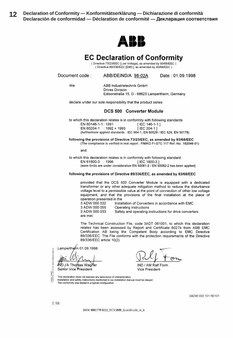
I 98
Declaration of Conformity — Konformitätserklärung — Dichiarazione di conformitàDeclaración de conformidad — Déclaration de conformité — Декларация соответствия
12
I 99
Declaration of Incorporation — Herstellererklärung — Dichiarazione di incorporazioneDeclaración de homologación — Déclaration d'incorporation — Декларация обиспользовании
3ADW 000 036 R0401

I 100
I 101
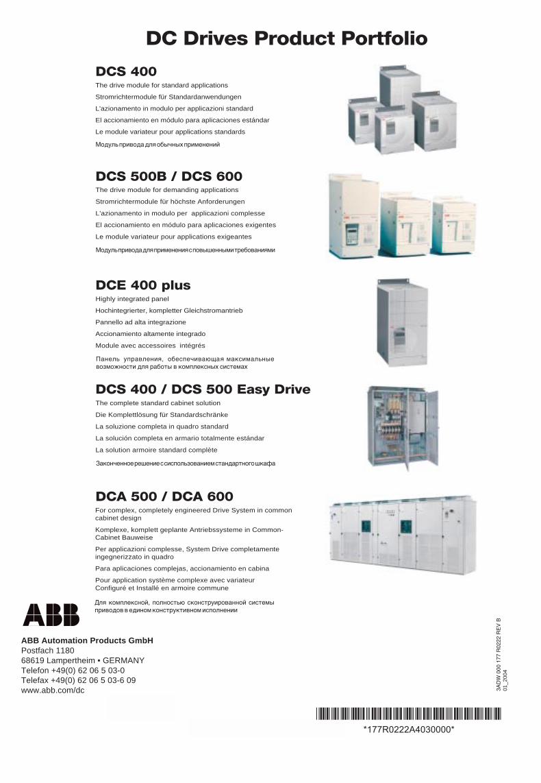
I 102
3ADW000177R0200_DCS500B_QuickGuide_edisf_b
3AD
W 0
00 1
77 R
0222
RE
V B
01_2
004
ABB Automation Products GmbHPostfach 118068619 Lampertheim • GERMANYTelefon +49(0) 62 06 5 03-0Telefax +49(0) 62 06 5 03-6 09www.abb.com/dc
DCS 400
DCS 500B / DCS 600
DCS 400 / DCS 500 Easy Drive
DCA 500 / DCA 600
DCE 400 plus
DC Drives Product Portfolio
The drive module for standard applications
Stromrichtermodule für Standardanwendungen
L'azionamento in modulo per applicazioni standard
El accionamiento en módulo para aplicaciones estándar
Le module variateur pour applications standards
The drive module for demanding applications
Stromrichtermodule für höchste Anforderungen
L'azionamento in modulo per applicazioni complesse
El accionamiento en módulo para aplicaciones exigentes
Le module variateur pour applications exigeantes
Highly integrated panel
Hochintegrierter, kompletter Gleichstromantrieb
Pannello ad alta integrazione
Accionamiento altamente integrado
Module avec accessoires intégrés
The complete standard cabinet solution
Die Komplettlösung für Standardschränke
La soluzione completa in quadro standard
La solución completa en armario totalmente estándar
La solution armoire standard complète
For complex, completely engineered Drive System in commoncabinet design
Komplexe, komplett geplante Antriebssysteme in Common-Cabinet Bauweise
Per applicazioni complesse, System Drive completamenteingegnerizzato in quadro
Para aplicaciones complejas, accionamiento en cabina
Pour application système complexe avec variateurConfiguré et Installé en armoire commune
Модуль привода для обычных применений
возможности для работы в комплексных системах
Модуль привода для применения с повышенными требованиями
Законченное решение с сиспользованием стандартного шкафа
Для комплексной, полностью сконструированной системыприводов в едином конструктивном исполнении
Панель управления, обеспечивающа я максимальные
*177R0222A4030000**177R0222A4030000*
Recommended