DEDICATEDSOLAR SORTIE MISSION
SO-01-SSORTIE PAYLOAD
Volume III of VI
Prepared for
National Aeronautics and Space AdministrationMarshall Space Flight Center
Huntsville, Alabama
by
Grumman Aerospace CorporationBethpage, New York 11714
Contract No. NAS 8-31102
Mission No. 13March 1974 Traffic Model
https://ntrs.nasa.gov/search.jsp?R=19750012362 2020-02-21T22:11:01+00:00Z
MISSION #13 - DEDICATED SOLAI SORTIE MISSION (SO-01--S
SORTIE PAYLOAD
FUNCTIONAL FLOW DESCRIPTIONS AND PAYLOAD
REQUIREMENTS FOR GROUND AND LAUNCH SUPPORT FACILITIES
Block 1.0 - Activities - Payload Premission Processing
The functional descriptions and launch support facility requirements which
follow are based upon:
o DSSM Definition and Requirements Data, Level B, dated
June 7, 1974.
o Spacelab, Preliminary Technical Description for use in Payload
Accommodation Studies, dated 14 June 1974.
o Launch Site Facility Requirements for Shuttle Payloads (NASA-MSFC),
dated May 20, 1974, (functional flow diagrams).
It should be noted that Level B Data is not detailed to the degree required
in some cases to determine facility requirements parameters in specific
quantitative values. To enhance Study results, assumptions are included where
needed. For example, three experiments in the payload require liquid nitrogen
for cooling and no requirement for supply of liquid nitrogen is contained in the
Level B data. The Study made the assumption that a pallet-mounted liquid nitrogen
dewar would furnish the liquid nitrogen, and expended gas was vented overboard
through suitable discharge fluid lines.
Another illustration is that the Level B data does not contain a layout of
the seventeen experiments in the Orbiter Cargo Bay. The Study assumes the larout
as shown in Figure 1-1, and utilizes information contained in the Spacelab,
Preliminary Technical Description noted above.
In addition, the Level B data does not include a definition.of the equipment
in the Orbiter Cabin (PSS, MSS, and other), and this equipment has been omitted
in the study.
MISSION #13 - DEDICATED SOLA. SORTIE MISSION (SO-01--S)
SORTIE PAYLOAD
FUNCTIONAL FLOW DESCRIPTIONS AND PAYL)AD
REQUIREMENTS FOR GROUND AND LAUNCH SUPPORT FACILITIES
Block 1.0 - Activities - Payload Premission Processing
The functional descriptions and launch support facility requiremcnts which
follow are based upon:
o DSSM Definition and Requirements Data, Level B, dated
June 7, 19 7 4.
o Spacelab, Preliminary Technical Description for use in Payload
Accommodation Studies, dated 14 June 1974.
o Launch Site Facility Requirements for Shuttle Payloads (NASA-MSFC),
dated May 20, 1974, (functional flow diagrams).
It should be noted that Level B Data is not detailed to the degree required
in some cases to determine facility requirements parameters in specifi:
quantitative values. To enhance Study results, assumptions are included where
needed. For example, three experiments in the payload require liquid nitrogen
for cooling and no requirement for supply of liquid nitrogen is contained in the
Level B data. The Study made the assumption that a pallet-mounted liquid nitrogen
dewar would furnish the liquid nitrogen, and expended gas was vented orerboard
through suitable discharge fluid lines.
Another illustration is that the Level B data does not contain a layout of
the seventeen experiments in the Orbiter Cargo Bay. The Study assumes the larout
as shown in Figure 1-1, and utilizes information contained in the Spacelab,
Preliminary Technical Description noted above.
In addition, the Level B data does not include a definition of the equipment
in the Orbiter Cabin (PSS, MSS, and other), and this equipmen has been omitted
in the study. R010GINALOFp pooL AG S
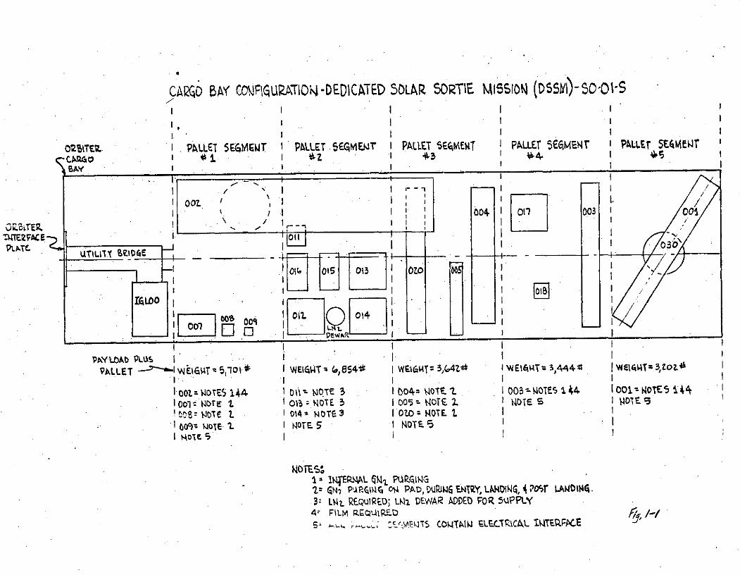
CARQ0 BAN' CNF ZM -EIAE 5OLAR. SORTIE MISION D515c 1s
IiTI 'PLEIEMW PLE 5MW I PLE WRT I IALT5 ET ALTS4AW
0 It
004,Tf 001
IAO FOI B
I EE Do 001
PA~Y LOAD PLUS6
PALLET Wt4 510 1 WEIGWT~ 4,)51 I W&1614TZ- 5,(,4Z0 I WEIAHTz 3,444:0 IwEIr9T-3,ZozL'
I007. cm MTE5 144 IOil NOTE 3 1 00 O4 ~ 0 -OE 1401-NT:Iool. NO~TE -L 01 T 0 E2 OlT:0 S I MT
tcs= 4ole 1 01D4% NOre,3 IooMT60tmlI NOTE 5 1NOTE.95I
KOTE 5C
11~~P NERrMA I WZIV' E N. PARQ14r 0j4 PAD, DUPJW& ENZY LIW1N, 4~osr LAWD1144.
3:Lvi R.EQuIRED; L~ DEWAR ADDED 'FOR 5tAPPLY4z FILM Rg I-,IR Z
51 ~~t CONTAMW ELFCfC4,L TITEPLFACE
Block 1.1 (Configure Experiment Secticn Pressure Shells) through Block 1.7
(Mate Special Experiment Sections) do not apply to the DSSM.
Block 1.5 - Load and Verify Flight Software - requires equipment not available
in the processing flow as shown, and therefore, Block 1.5 has been inserted later
in the flow, between Blocks 1.12 and 1.13.

Block 1.8 Receive and Inspect Pallet Sections
Block 1.8.1 Pallet Sections arrive at launch site via air transportation.
Figure 1-2 shows the anticipated con iguration of the largest size pallet segment
(Pallet Segment #1) upon arrival at launch site. This pallet segment is flowed
through the Payload Premission Processing. Other pallet segments have similar
flow; however, differences are described when occurring. Some experiments
require GN2 pruging, and it is assumed tha he purging function involves a G12blanket pressure with a GN2 supply to furnish pressure decay caused by leakage.
In the transportation mode, the GN2 supply is included in the shipping container
as GSE which is shown in Figure 1-2.
The logic of selecting air transportation for the pallet segments from the
NASA DSSM Development Center to the launch site is based upon the size and
weight of pallet segment shipping containers (suitable for C5A aircraft), and
the advantage of short travel time and transportation control afforded by C5A
transport versus rail/truck/sea transport.
Ground and Launch Support Facility Requirements
This block establishes the initial conditions of the pallet segments upn
arrival at the launch site, and does not involve ground and Launch support
facility requirements.

, • - - - I : .'
~ ~~~~ ~~ --- ..... r-:' -- i i , , i j'F . - . . ..
• ,- ! -I [I t' ,i :~ i 1: , I ..,...... ,. v . I. .. .. .. .... ... . ..
,, I ! :- ' " i- i -i- -' - i- - ' - ,- - - ,. .. .. .
!60a9 . i , --: -.-- -: , I\ i:Wi i•~ , I ; i : I i ... -. . I .. . .' .. . ...
S--Tr-igcyljOo& I I I.. .-- -: ;.-
-7-F
_- F j---- -- --I ---- !7' .
m e -or ' : , V Ji - ..... ' f . .- ...... .
"~ !.I- .. i_ ' . . . ..I ! . . I ...r .. .. .. .. .. - .... .. . . .. .. ..- --. ... . .- " -
- - --- ;, • i .; I L J ' ... ..
i i 1
' i- " i- - !- ; ] I .. ..
I ,.
F " ,i- - I
-i- i i . .. ... --i --- i~. I._~.i..~ i--- - - - ..
F F....- - i i
.. .. .. . . ~... .... ... .. . L .. ... . ... _. .. .. ~... .. . . . .-------- ---- . .. . . . . . .. ..
Block 1.8.2 Unload Pallet Sections from Commercial Carrier and Place
in Temporary Storage
The pallet segment in its shipping container is removed from the C5A
aircraft, loaded on a flat-bed trailer, towed to a temporary protected storage
area, and unloaded from the trailer.
Ground and Launch Support Facility Reuirements
Facility Requirements
o Protected storage area (hangar-type protection satisfactory)
- 75 feet long, 35 feet wide, and 20 feet high for five pallet
segments which allows six foot aisle between shipping containers.
o GN2 supply (contingency for experiment pruging).
o Refrigerated film storage.
Support Requirements
o Air Force 463L Material Handling System (for unloading C5A aircraft).
o Flat-bed trailer (10,000 lbs. capacity, 25 feet long, 10 feet wide).
o Tow tractor (for flat-bed trailer).
o Crane, mobile (8,000 lbs. capacity).
o Pallet Segment Shipping Container Hoisting Sling.
o Operators for tow tractor, crane, and 463L Material Handling System.
o Riggers
o Traffic Security Personnel
Block 1.8.3 Transport Pallet Sections from Temporary Storage to Receiving /Area of PPF
The pallet segments are removed from temporary storage and transported to
the receiving area of the PPF to meet the requirements of the Orbiter launcl
schedule.
The functional flow described generates an even distribution of work for
the tasks of pallet segment unpacking, pallet segment interface verification,
and pallet segment installation in the Holding Fixture (Cargo Bay Simulator).
The unpacking is accomplished in series, the interface verification in parallel,
and the installation in series.
Ground and Launch Support Facility Requirements
Facility Requirements
o Receiving area of PPF
- 35 feet long, 20 feet wide, and 20 feet high, with entry door
19 feet high, 13 feet wide.
o GN2 supply (contingency for experiment purging)
Support Requirements
o Flat-bed trailer (10,000 lbs. capacity, 25 feet long, 10 feet wide).
o Tow tractor (for flat-bed trailer).
o Crane, mobile (8,000 lbs. capacity).
o Operators for tow trailer and crane.
o Riggers.
o Pallet Segment Shipping Container Hoisting Sling.
o Traffic Security Personnel.
Block 1.8.4 Unpack Pallet Sections and Place in Holding Fixture
(Movable, and 2mulates Orbiter Cargo Bay)
Various concepts were considered for unpacking the pallet segments. T1
one described below distributes work tasks throughout the PPF. The selectee
unpacking procedure follows:
Step 1 - Position Holding Fixture alongside flat-bed trailer.
Step 2 - Remove roof bulkhead of pallet segment shippinh container,
and hoist clear.
Step 3 - Attach hoisting sling to pallet segmen,, and hoist vertically
clear of shipping container, translate to Holding Fixture, and lower
in place.
Step 4 - Replace roof bulkhead of shipping container.
Step 5 - Open PPF door, and tow shipping container to temporary protected
storage.
The recommended "Holding Fixture" for the DSSM is a Cargo Bay Simulator
(CBS) and is conceptually defined as a movable fixture which duplicates the
Orbiter Cargo Bay as concerns mounting provisions, mechanical clearances
including Cargo Bay Doors, manipulator installation, and all electrical and
fluid interface connections. The CBS is wheeled to permit movement within the
PPF, and serves as the transporter for payload transfer from PPF to CPF. The
CBS in modular in construction, that is, built up in sections (such as, 10 ft.
or 15 ft.), such that forward and aft bulkhead sections contain the wheels.
Thus, for the DSSM whose total length in the Cargo Bay is estimated to be 60 ft.,
the CBS is built-up on one forward bulkhead section of 10 ft., one aft bulkhead
section of 10 ft., and four 10 ft. middle sections for a total length of 60 ft.
(ten foot sections used for illustration).
After installation of the first pallet segment in the Cargo Bay Simulator
(CBS), the CBS is moved to the checkout area of the PPF where interface verification
tests are begun.
The other pallet segments are transported from temporary storage to the PPF
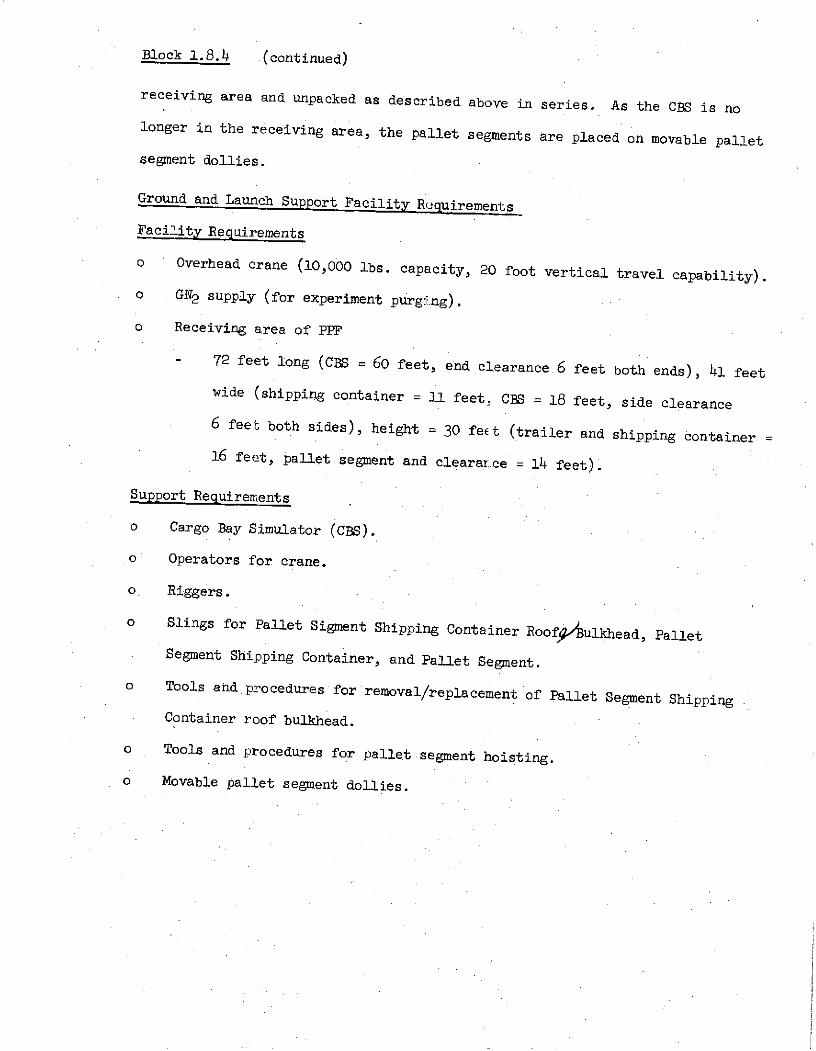
Block 1.8.4 (continued)
receiving area and unpacked as described above in series. As the CBS is no
longer in the receiving area, the pallet segments are placed on movable pallet
segment dollies.
Ground and Launch Support Facility Requirements
Facility Requirements
o Overhead crane (10,000 lbs. capacity, 20 foot vertical travel capability).
o GN2 supply (for experiment purging).
o Receiving area of PPF
- 72 feet long (CBS = 60 feet, end clearance 6 feet both ends), 41 feet
wide (shipping container = 11 feet. CBS = 18 feet, side clearance
6 feet both sides), height = 30 feet (trailer and shipping container
16 feet, pallet segment and cleararce = 14 feet).
Support Requirements
o Cargo Bay Simulator (CBS).
o Operators for crane.
o, Riggers.
o Slings for Pallet Sigment Shipping Container Roof9/ulkhead, Pallet
Segment Shipping Container, and Pallet Segment.
o Tools and procedures for removal/replacement of Pallet Segment Shipping
Container roof bulkhead.
o Tools and procedures for pallet segment hoisting.
o Movable pallet segment dollies.
Block 1.8.4.1 Transport Pallet Sections Shipping Containers to Temporary/Long
Term Storage
This block removes the Pallet Segment Shipping Containers from the receiving
area of the PPF, and returns them to temporary protective storage (one to two
months). It is assumed that after the seven day orbit mission the shipping
containers will be reused to return he pallet segments to the NASA DSSM
Development Center.
Ground and Launch Support Facility Requirements
Facility Requirements
o Protective storage area
- Same as Block 1.8.2
Support Requirements
o Flat-Bed trailer (2,000 lbs. capacity, 25 feet long, 10 feet wide)
o Tow tractor (for flat-bed trailer).
o Crane,.mobile (2,000 lbs. capacity)
o Pallet Segment Shipping Container hoisting sling.
o Operators for tow tractor and crane.
o Riggers
o Traffic Security personnel.

Block 1.8.5 Conduct Visual Inspection, and Record Transport Sensor Readings
to Verify Post-transp, rtation Integrity
Level B data does not specify transport sensors in the DSSM; however, it
is anticipated that accelerometers, desiccants, GN2 pressure indicators and the
like will be installed to verify post-transportation integrity.
The data of these sensors are recorded and visual inspection of the pallet
segment is performed.
Ground and Launch Support Facility Requirements
Facility Requirements
o GN2 supply (continued)
Support Requirements
o Procedures and inspection tools (flash light, mirror, etc.) for recordiLng
sensor and performing visual inspection.
Block 1.8.6 Move Pallet Sections (in Holding Fixture) to Checkout Area in PPF
A pallet segment in the Cargo Bty Simulator (CBS) is towed to the checkout
area in the PPF. As scheduled, the other four pallet segments are moved on
their movable pallet segment dollies to the PPF checkout area.
Ground and Launch Support Facility Requirements
Facility Requirements
o GN2 supply continues.
o PPF Checkout Area
- 80 feet long (CBS = 60 feet, 10 feet work stands both ends), 35 feet
wide (CBS = 15, 10 foot work stands both sides), and 39 feet height
(CBS = 18 feet, payload - 15 feet, and 6 fcot clearance).
Support Requirements
o Tow tractor for CBS and pallet segment dollies.
o Operator for tow tractor.

Block 1.8.20 Pallet Sections GSE Arrives at Launch Site Via
The pallet segment GSE arrives at the launch site via C5A aircraft and to
the extent practical for C5A load, in the same aircraft with its supported
pallet segment.
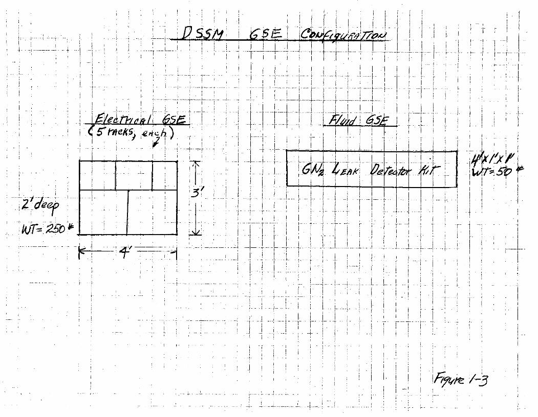
Level B data does not contain definition of DSSM GSE. For purposes of
the Study, the DSSM GSE configuration to verify interfaces between pallet
segments, and between the integrated DSSM and the Orbiter, is shown in Figure
1-3.
Ground and Launch Support Facility Requirements
This block establishes initial conditions fo DSSM GSE upon arrival at the
launch site, and does not require ground and launch sapport facility
requirements.
1 V
I q
avI
AI1- Z70.
-4.-- ~~7I -r-- I"lie
Block 1.8.21 Unload GSE from Commercial Carrier and Place
in Temporary Storage
The DSSM GSE, assumed to be five racks of electrical equipment and one GN2leak detector kit, is removed from the C5A aircraft, and placed in temporary
protective storage until required for PPF processing.
Ground and Launch Support Facility Requirements*
Facility Requirements
o Protected storage area (Hangar - type satisfactory)
- 30 feet long, 24 feet wide, 5 feet high
Support Requirements
o Air Force 463L Material Handling System (for unloading C5A aircraft).
o Fork lift truck.
o Trucks (22 ton, closed body).
o Operators for fork lift trucks, and 2- ton turcks.
o Inventory Management.
Block 1.8.22 Transport GSE from Temporary Storage to Receiving Area of PPF
As required for DSSM processing, the DSSM GSE is moved from temporary
storage to the receiving area of the PPF.
Ground and Launch Support Facility Requirements
Facility Requirements
o PPF receiving area (area for two electrical GSE racks)
- 20 feet long, 16 feet wide, 4 feet high
Support Requirements
o Fork lift trucks.
o Trucks (2- ton, closed body).
o Operators for fork lift trucks and 2- ton trucks.
o Inventory Management.
Block 1.8.23 Unpack GSE, and Place on Dolly
In the receiving aiea of PPF, ti e DSSHGSE is unpacked, and placed on
movable utility dollies.
Ground and Launch Support Facility Requirements
Facility Requirements
o None
Support Requirements
o Fork lift trucks.
o Movable utility dollies (5 feet long, 3 feet wide).
o Operators for fork lift trucks.
o Tools and procedures for uncrating DSSM GSE.
o Technicians for uncrating operations.
Block 1.8.23.1 Transport GSE Shippin! Contt:iners to Temjorilry Stor ye
After uncrating the DSSM GSE, the shipping containers ar transported from
PPF to temporary storage. It is anticipated that the DSSM GS will re-use the
shipping containers after Orbiter launch for return of DSSM SE to the NASA
DSSM Development Center.
Ground and Launch Support Facility Requirements
Facility Requirements
o Temporary storage area.
- 30 feet long, 24 feet wide, 5 feet high
Support Requirements
3 Fork lift trucks.
o Trucks (2 ton)
o Operators for fork lift trucks and 2- ton trucks.
o Inventory Management.
o Tools and procedures for reassembly of shipping containers.
Block 1.:i.24 Conduct Visual Inspection and Record Sensor Readings to
Verify Post-transportation Integrity
The assumption is made that the DSSM GSE has no installed transport sensors,
so sensor recordings are not applicable.
A visual inspection of the DSSM GSE is made to verify post-transportation
integrity.
Ground and Launch Support Facility Requirements
Facility Requirements
o None
Support Requirements
o Procedures and inspection tools (flash light, mirrors, etc.) for performing
visual inspection.
o Technicians for conducting inspection.
Block 1.8.25 Move GSE to Checkout Area of PPF
The DSSM GSE, mounted on movable dollies, is moved from the receiving area
to the checkout area in the PPF.
Ground and Launch Support Facility Requirements
Facility Requirements
o PPF Checkout area.
- 12 feet long, 8 feet wide, 4 feet high for utility dollies.
Support Requirements
o None
Block 1.9 Install Crew Transfer Access Tunnel and Aft Bulkhead
(This block is not applicable to Study. For DSSM, a pallet only mission,
there are no tunnel and aft bulkhead.)
Block 1.10 Mate Pallet with Pressurized Sections
NOTE: This block has been changed to include verification test ojhe
Pallet Sections interfaces prior to ccnnecting the Pallet
Sections together. The justification for this change is that
malfunction detection is more economical and has less probability
of impacting the Shuttle launch schedule when performed on a
"build-up" basis instead of an a "system" basis. In addition,
the DSSM pallet segments have not been functionally checked since
launch site arrival, and to delay the Theck until after all f ve
pallet segments have been joined would appear to invite dupli ation
of installation/removal activities and resulting increases in time
requirements and costs for ground operations.
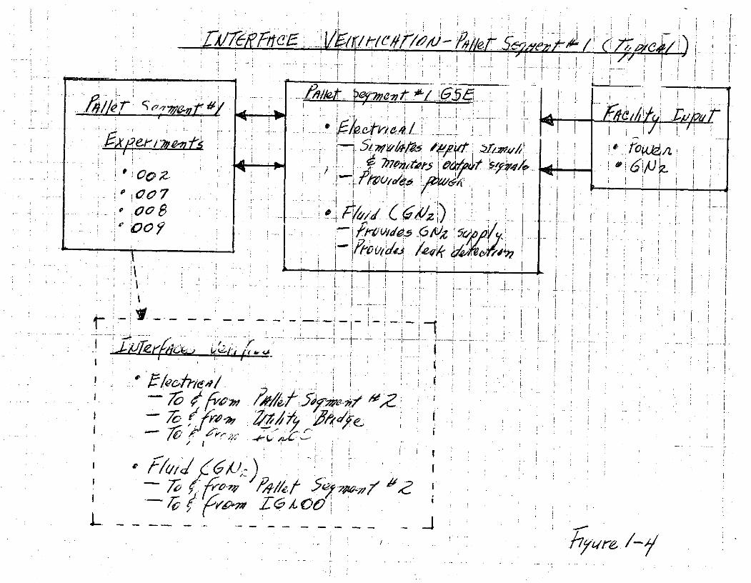
The activities in Block 1.10 are to verify the pallet segment
interfaces prior to installing the pallet segrents into the
Cargo Bay Simulator (CBS). One typical interiace verification
test in block diagram form is shown in Figure 1-4.
I -II
____ ____ ____- ///e/5ez~i~ /(77
p I
70~~~~ OrI~ 1e I___ I4e
I _______________________
6;
Block 1.10.1 Perform Functional Check and Calibration of GSE
It is assumed that the Pallet Segment GSE requires no calibration, and
that the functional check of the GSE is conducted using standard test equipment.
Since the definition of DSSM GSE is TBD, the requirements for standard test
equipment is TBD at this time.
Ground and Launch Support Facility Requirements
Facility Requirements
o Electrical Power - TBD
o Calibration Lab - TBD
o GN2 - TBD
Support Requirements
o Standard test equipment - TBD
o Checkout/Calibration Procedures - TBD
o Technicians to perform checkout/calibation

Block 1.10.2 Connect GSE to Pal Let Sections Requiring Culibration,
and Calibrate Pallet Sections
level B data of DSSM does not identify calibration riequirements for the
experiments, therefot e, these requirements are TBD.
Ground and Launch Support Facility Requirements
o TBD
O]F0 QUAL PAG ioP~~ oo UALn j

Block 1.10.3 Connect GSE to Pallet Sections Interfaces
Block 1.10.4 Perform Verification Tests of Pallet Sections Interfaces
Block 1.10.5 Remove Pallet Sections Verification GSE
The three blocks conduct the pallet segment verification tests. Figure
1-4 shows a typical pallet segment verification test interconnections, ani
indicates the interfaces verified. For Pa let Segment #1. GN2 interfaces
between the segment and the IGLOO and Pallet Segment #2 a:'e tested. The GSE
siZulates the input/output of the Pallet Segment #2 and the IGLOO.
In like manner, the electrical interfaces are verified. For Pallet Segment #electrical interfaces exist with Pallet Se;ment #2, the IGLOO, and the Utility
Bridge.
During these tests, GSE furnishes electrical power and GN2 to Pallet
Segment #1. The GSE in turn is supplied these items by the facility.
Ground and Launch Support Facility Requirements
Facility Requirements
o GN2 - TBD
o Electrical Power - TBD
Support Requirements
o Tools and procedures for mating/unmating GSE.
o Procedures for conducting verification tests.
o Data/Computer processing (parameters - TBD).
o Refrigerated Film Storage.
o Electrical and Fluid Technicians.
NOTE: Data Sheet #S-23 - Ground Facility Requirements - of the DSSM Level B
4d: data indicates various launch site ground facility requirements which
do not appear appropriate for Level II integration activities. As an
example, an altitude chamber, a vacuum chamber, and a solar simulator/
gamma ray source are listed as launch site ground facility requirements

Block 1.10.5 (continued)
NOTE: (continued)
on Data Sheet #S-23. It is felt that these items would not be involved
in performing Level II integration activities at the launch site, and
such requirements have been omitted from the Study.
Block 1.10.6 Inspect Pallet Sections to Verify Configuration is Correct
for mating with Pressurized Sections
This inspection is performed to verify that the Pallet Segments are in the
proper configuration for installation into the Cargo Bay Simulator.
All mechanical, fluid, and electrical interfaces of the Pallet Segments
are inspected for correct configuration.
Ground and Launch Support Facilities Requirements
Facility Requirements
o None
Support Requirements
o Inspection procedures, tools, and configuration descriptions/drawings
of mechanical, fluid, and electrical interfaces..
o Mechanical/fluid/electrical Technicians.
Block 1.10.7 Mate Pallet Sections with Pressurized Sections
This block installs the Pallet Segments in the Cargo Bay Simulator (CBS),
and mates the pallet segments.
Prior to installing the pallet segments into the CBS, an inspection of
the CBS is conducted to verify that the CBS is configured -correctly to receive
the pallet segments.
The Pallet Segments, located on movable pallet segment dollies, are hoisted
from the dollies by an overhead crane, and lowered into their position in the
CBS.
Once in the CBS, all mechanical, fluid, and electrical interfaces between
pallet segments are mated.
The IGLOO and Utility Bridge have their interfaces verified, and then
they are installed in the CBS. After these items are in place in the CBS,
the interface connections are made.
This block concludes with all Orbiter Cargo Bay equipment installed in the
CBS, and ready for Orbiter Simulator verification test (.Manad Final Integrated
Systems Tests - Block 1.13).
Ground and Launch Support Facility Requirements
Facility Requirements
o PPF checkout area
- CBS area; 80 feet long, 35 feet wide, 39 feet height.
- Pallet Segment area; 15 feet long, 10 feet wide, and 18 feet height.
o Overall crane (8,000 lbs. capacity).
Support Requirements
o Procedures and tools for configuration inspection of CBS.
o Procedures and tools for hoisting pallet segments.
o Slings for hoisting pallet segments.
o Procedures and tools for mating mechanical, fluid, and electrical interface
connections between pallet segments.
o Procedures and tools for verifying IGLOO and Utility Bridge interfaces
Block 1.10.7 (continued)
Support Requirements (continued)
o Procedures and tools fo ating IGLOO and Utility Brid;:e Lnterfaces.
o Mechanical/fluid, and electrical technicians.
o Riggers.
o Operator for overhead crane.

Block 1.11 Mate Pallet Sections with Liaison Pallet
This block is not applicable to the DSSM flight.

Block 1.12 Connect Orbiter Simulator
This block is not applicable to the Study. (However, the following comments
are offered.
It is recommended that the forward bulthead of the "Holding Fixture" -
called the Cargo Bay Simulator in this Stud;- - duplicate the forward end of the
Orbiter Cargo Bay, which then serves as an nterface simulator between the
Spacelab and the Orbiter. The equipment of the Orbiter Simulator would be a
series of rack-mounted equipment on dollies which simulate the Orbiter PSS/MSS,
and cabin mounted payload equipment. The forward bulkhead of the CBS would
have provisions for mounting a manipulator rig in case functional verification
tests between the manipulator and payload are accomplished during ground
operations in the PPF.
The Level B data for DSSM indicates that the pressurized equipment will be
provided by Spacelab (Data Sheet #S-5). In addition, Data Sheet S-7a and -7bindicate other equipments to be located in a pressurized area. The Orbiter
Simulator simulates all such equipment as this).
Block 1.5 Load and Verify Flijpht Software
All equipment is now assembled for flight software verification; that is,
Orbiter Simulator as defined in Block 1.12 contains necessiry equipment located
in Orbiter, and the payload equipment completely installed in the Cargo Bay
Simulator, so that data channels are mated. It is anticiputted that the software
verification activity will be conducted by launch site per,;onnel, and therefore,
these activities are not detailed here.
Block 1.13 Final Integrated Systems Tests
This block verifies the interface between the Orbiter Simulator. and theseSpacelab elements which mate with the Orbiter Simulator. This definition is inkeepin- with the grouneule of verifying interfaces at the launch site, ajidsince all interfaces within the Pallet Segments, IGLOO, and Utility Bridge havebeen verified previously in the functional flow processing, only the interface
between the Orbiter Simulator and the Orbiter Interface Plate (Figure 1-1)located on the CBS forward bulkhead requires verification during the final
integrated systems tests.
The concept of the Orbiter Simulator is defined in Block 1.12 above.
The interfaces verified in this block are based upon those contained in
JSC 07700, Volume XIV, "Payload Accommodations".
Block 1.13.1 Verify Structural/Mechanical Interfaces
Block 1.13.1.1 Mechanical Verification of Transfer Tunnel Fitting on
Payload Bay Hatch
This block is not applicable to DSSM.
Block 1.13.1.2 Mechanical,'Fluid, Electrical Verification of Service Panel
Connections on Spacelab
Level B data does not contain definition of the supply of GN2 and LN2 for
the experiments if these fluids are serviced through.the Orbiter Service Panel,
these interfaces would be verified.
Block 1.13.2 Verify Avionics Interfaces
The following avionics interfaces are verified in the DSSM
o Data Processing and Software Subsystem.
o Communications and Tracking Subsystem.
Block 1.13.3 Verify Electrical Power Subsystem Interface
This interface is verified at the Orbiter Interface Plate (Figure 1-1).
Block 1.13.4 Verify the Environmental Control and Life Support
(ECLS) Subsystem Interfaces
Block 1.13.4.1 Verify the Atmospheric Revitalization Subsystem (ARS) Inter 'aces
The DSSM contain no ARS interface.
Block 1.13 .4.2 Verify the Active Thermal Control Subsystem (ATCS) Interfaces
The DSSM Level B data does not include ATCS requirements.
Ground and Launch Support Facility Requirements for Block 3.13
Facility Requirements
o Electrical Power - TBD.
o GN2 -TBD.
Ground and Launch Support Facility Requirements for Block 1.13 (continued)
Support Requirements
o Orbiter Simulator.
o Verification Test Procedures.
o Electrical, Fluid, and Mechanical Technicians.
o Data processing (parameters are TBD).
Block 1.14 Service Non-time Critical Items
The DSSM Level B data does not include servic(, requiremlents (non-time
critical). Candidates include the servicing of GN, supply for instrument pvlrging.
If the IGLOO supplies the purging GN2, the servicing of GN2 would be performed
in this block.
Ground and Launch Support Facility Requirements
Facility Requirements
o Electrical Power - TBD
o GN2 - TBD.
Support Requirements
o GN2 Control Cart.
o Procedures for GN2 servicing.
o Fluid Technicians.

Block 1.15 Perform Pressure Integrity Tests
This block is not applicable to the DSSM.
Block 1.16 Disconnect Orbiter S:mulator
This block disconnects the int rfaces between the Orbiter Simulator anc the
Cargo Bay Simulator (CBS), and secures the CBS interfaces ir preparation fo)
moving the CBS from the PPF to the OPF.
The Orbiter Simulator is assumed to contain various rac-mounted DSSM
eluipment which is located in the Orbiter Cabin (PSS/MSS) during the flight
mission. This equipment is called DSSM Cabin Equipment in tie functional
activities described below.
Block 1.16.1 Disconnect Interfaces between Orbiter Simulator and CBS
The Orbiter Interface Plate (Figure 1-1) connections are unmated. This
interface is primarily electrical, although there may be fluid lines for supply
of GN2 to the IGLOO, and for exhaust.GN2 discharge lines from expended LN2 .
Block 1.16.2 Install Protective Covers on Orbiter Interfaces Plate
A protective cover is installed over the Orbiter Interface Plate for
environmental protection during the transport of the CBS from PPF to the OPF.
Block 1.16.3 Disconnect Interfaces between Orbiter Simulator and DSSM
Cabin Equipment
The interfaces between Orbiter Simulator and DSSM Cabin Equipnment are
unmated. Although mainly electrical, these interfaces also involved mechanical
release of the racks and individually mounted equipment.
Block 1.16.4 Install Protective Covers on DSSM Cabin Equipment
Protective covers are placed over the DSSM Cabin Equipment for environmental
protection during transport from PPF to OPF.
Ground and Launch Support Facility Requirements
Facility Requirements
o Overhead crane (capacity 1,000 lbs.)

Ground and Launch Support Facility Requirements
Support Requirements
o Procedures and tools for disconnecting interfaces at Orbiter Interiace
Plate.
o Procedures and tools for dis onnecting interfaces between Orbiter Simulator
and DSSM Cabin Equipment.
o Protective covers, installation procedures, and tools for Orbiter Ilterfac,
Plate and DSSM Cabin Equipment.
o Fork lift trucks.
o Operators for overhead crane and for.: lift truck.
o Mechanical/electrical technicians.
Block 1.17 Move to OPF
This block moves the Cargo Bay Simulator (CBS) and the DSSM c(abin Equipment
from the PPF to the OPF. The CBS is towed, and the DSSM Cabin Eqlipment is
loaded in closed-body trucks whic' transport the equipment to the OFF.
The concept of the CBS includes a closed container which affords protection
to the pallet-mounted instruments during transit. However, some of the instrumeni
may require GN2 purge during the move; therefore, a supply of GN2 is included in
the ground requirements.
Block 1.17.1 Perform Functional Check, Calibration, and Service GSE as Required
A supply of GN2 may be required during transport from PPF to OPF. BottlEd
GN2 with appropriate valving would satisfy this requirement.
Block 1.17.2 Position GSE on Trailer which Accompanies Cargo Bay
Simulator during Tow from PPF to OFF
The GN2 bottle would be installed adjacent to the IGLOO, and connected to
the IGLOO GN2 supply.
Block 1.17.3 Install Protective Covers on Pallet-mounted Experiments
It.is anticipated that this block is not applicable to the DSSM, since the
experiment protective covers have not been removed.
Block 1.17.4 Connect GSE to Protective Covers
This block is not applicable to the DSSM.
Block 1.17.5 Power up GSE and Supply Cleanliness Requirements, and
Monitor GSE Output
This block is not applicable to the DSSM.
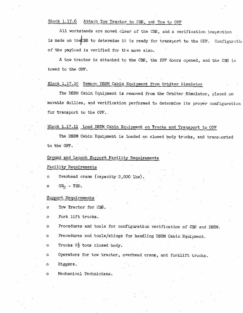
Block 1.17.6 Attach Tow Tractor to CBS, ard Tow to OPF
All workstands are moved clear of the CBS, and a verification inspection
is made on th BS to determine it is ready for transport to the OPF. Configuratie
of the payload is verified for the move also.
A tow tractor is attached to the CBS, the PPF doors opened, and the CBS is
towed to the OFF.
Block 1.17.10 Remove DSSM Cabin Equipment from Orbiter Simulator
The DSSM Cabin Equipment is removed from the Orbiter Simulator, placed on
movable dollies, and verification performed to determine its proper configuration
for transport to the OFF.
Block 1.17.11 Load DSSM Cabin Equipment on Trucks and Transport to OPF
The DSSM Cabin Equipment is loaded on closed body trucks, and transported
to the OPF.
Ground and Launch Support Facility Requirements
Facility Requirements
o Overhead crane (capacity 2,000 lbs).
o GN2 - TBD.
Support Requirements
o Tow Tractor for CBS.
o Fork lift trucks.
o Procedures and tools for configuration verification of CBS and DSSM.
o Procedures and tools/slings for handling DSSM Cabin Equipment.
o Trucks. 2 tons closed body.
o Operators for tow tractor, overhead crane, and forklift trucks.
o Riggers.
o Mechanical Technicians.

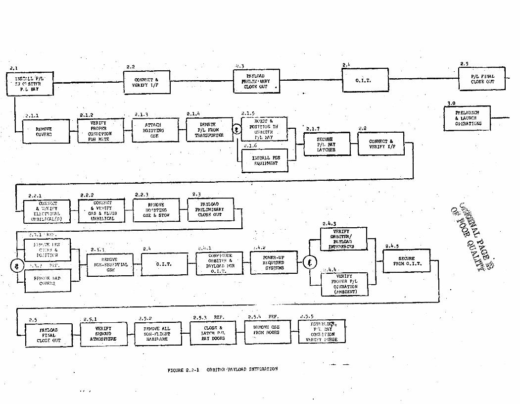
Block 2.0 Orbiter/Payload Integration and Checkout - Mission No. 13
The activities in this functional block begin with the arrival of the
integrated payload elements at the mating area of the Orbiter Processing
Facility and include all those efforts required to physically and function-
ally mate the payload to the Orbiter Payload Bay, and in;tall sliy equipment
required for the mission in the Payload Specialist Station. Figure 2.2-3
graphically depicts this flow.
The.prerequisites of entering this block are as follows:
o All elements requiring integration have been integrated.
o Required GSE, STE, facility services and personnel are available.
o Orbiter processing has progressed to the required point in its
turnaround flow and is ready to '.ccept the Payload.
Block 2.1 Install Payload in Orbiter Payload Bay
Conditions Payload is in position and access stands are in place.
Block 2.1.1 Lock transporter in position and remove all transport covers.
Block 2.1.2 Verify no transport damage has been incurred and payload and
associated hardware is in a mate condition (visual inspection).
Block 2.1.3 With the overhead crane in position, attach the auxiliary crane
control to the hook and the hoisting GSE to the crane control. Raise the
assembled functional set and attach to payload hoist points.
Block 2.1.4 . Using the auxiliary control, apply a load of TBD pounds as in-
dicated on the dial face. Unlatch all transporter hold down points and raise
payload clear of the transport unit.
Blok 2.1.5 Hoist and position in payload bay. Using the auxiliary control
lower onto the orbiter support points.
B 1,nck 2.1.6 Install all related mission equipment in the Payload Specialist
Station.
Block 2.1.7 Secure all payload bay latches and verify.
2,1 2.2 2.3 2.h 2.5
SLPC cR & PAYLOAD ." " P/L FINAL1, VLU P/C O O:CT & IL, ARY 'O.I.T, CLOSE OUT
PFOL BTAY P T
3.0
2.1.1 221.2 2.1.3 2.1.5 P .nAUCF
VFiry ATTACH) DEMATE o'rmTO; IN OPERATIAOTCERATIO
RMOVE PROPE IIOISTINO P/L FIOM !BET 2.1.7 .COVF.R: CONDIION GSF TWIU\N FTER
FOR rTE I'lAY "ECU CONNCT &-/ , 1AYr VERIFY I/F
INSTALL PS".QUIlENT
2.2.1 2.2.2 2.2.3 2.3
;COrN~ C :F CNEC REMOVE PAYLOAD& r Y & IFFY 1OTSTINC PRELIMINARY
ELECTI'.AL GAS & FLUID GSE & STOW CLOSE OUTRTICAL2.4.3
F IVERIFY
ORBITER/
PAYLOAD p 6c 2.3.3 2.1 ."_.4.2
.FACE 5
Ic TriU EE2IOVECorFIGWI Poll4n-UP SECURESNON-E AL O.I.T* PAYL R QURED FROM O.I.T.
S: O .. SST
REF! E ADIFYCOVrEl'S PROPER P/L
OPERATION(AMBIENT)
2.5 2.5.1 2.5.2 2.5.3 REF. 2.5.11 REF. 25.5
PAYLOAD VERIFY REMOVE ALL CLOSE & BI IRIIOV E GSE P i Y
FINAL SHROUD ION-FLIGHT LATCr P/r, IOM DOORS CO, frITOIONCLOSE OUT ATMOSPHERE RARDIIARE BAY DOORS V.IEIFY PURGE
FIGURE 2.2-1 ORBITR/PAYLOAD INTrFRATION
Support Requirements Functioial Block 2.1
Facilities
Floor space 2700 ft2 (90 x 30)
Overhead crane 10 ton capacity
GN
Ground Support Equipment
Hoist, Functional Set
Stands, Access
Auxiliary Crane Control
Support
Crane Operator
Personnel
Technicians
Q.C.
Safety
Engineering
Logistics
Procedures
Block 2.2 Connect and Verify Orbiter/Payload Interfaces
Conditions Payload is mechanically rlated to the Orbiter and latch-
down has been verified.
Blo:!k 2.2.1 Verify power off on both sides cf the electrical interface. When
verified, mate the Orbiter to Payload umbilical(s).
Block 2.2.2 Verify no pressure or fluid present at either side of the fluid/
gas umbilical.
Block 2.2.3 Disconnect hoisting GSE and hoist clear of payload bay, retain in
the area.
Support Requirements for Functional BLock 2.2
Facilities
Same as 2.1.

Support Requirements for Functional Block 2.2 (Continued)
Ground Support Equipmnent
Same as 2.1
Support
Crane Operator
Personnel
Technicians
Q.C.
Safety
Engineers
Logistics
Procedures
Block 2.3 Payload Preliminary Closeout
Conditions Payload has been physically and functionally mated to the
Orbiter.
Block 2.3.1 Remove protective covers from the Remote Manipu ator System (RMS)
arms. (Reference only not a payload function.)
Block 2.3.2 Remove protective covers from the payload bay door mounted radiators.
(Reference only, not a payload function.)
Block 2.3.3 Remove all non-essential GSE and stow. Retain in area.
Support Requirements for Functional Block 2.3
Same as 2.2.
Block 2.4 Perform Orbiter Integrate Test (OIT)
Conditions Preliminary payload closeout has been completed. Orbitersupport available and verified.
Block 2.4.1 Configure orbiter, payload and a;sociated GSE to support OIT posi-tion switches and circuit breakers per tes , procedures and verify.
Block 2.4.2 Apply ground power to the required systems and verify proper leveland distribution.
Block 2.4.3 Verify functional path through Orbiter/Payload interface paths.
Block 2.4.4 Verify proper signal format and level for all operating payload
elements.
Block 2.4.4.1 Figure 2.2-2 is a graphic representation of a typical anomaly loop
and indicates various options in effecting corrective action. Once the an-
omaly has been isolated, the decision on which path to follow will be a "real
time" decision based on repair requirements and/or mission criticality. It
is assumed that any anomaly associated with the Orbiter or the Institutional
Ground Support Equipment will be the responsibility of KSC operational pe2-
sonnel, while anomalies within the payload elements or Peculiar Ground Su -
port Equipment will be corrected by the payload operations personnel.
Block 2.4.5 Upon final verifications of the correct readouts and functional
interfaces, secure from O.I.T. power down active systems End position all
switches and circuit breakers as called for in the O.I.T. procedures.
Support Requirements for Functional Block 2.4
Facilities
Same as 2.1. plus 115 VAC 1 P 60 HZ (TBD KW)
and 110 VAC 400 HZ
Ground Support Equipment
GN2 Regulating Unit
Hose Set
Cable Set(s)
Service Set, LN2 b9 0
Support
None
Personnel
Technicians
Q.C.

2.4.5
VERIFIED SECUREFROM O.I.T.
ERIFYPROPER P/LCIPETION
NOT VERIFIED
ORBITER KSC RESPONSIBILITY
SWITCH TOLS E KSC RESPONSIBILITY BACK-UP
GROUND S E UNITISOLATE SUPORTP.OBLFM EQUIIYII OO LANOMALY
O REPAIR INPLACE
P/L, EL.14ENT,ANOMALY
IN PLACE " " REPAIR LABREIA tl & REPL
RFMOVE VERIFY& REPIACE . PROPER P/L
OPERATION
* REMOVE TOilF:IAIR LAB
NOTE: IEAIR & IEPLIGSE = INSTITUTIONAL GROUND SUPPORT EQ IIIPn'TPOSE * PAYLOAD PECUlLIAR GROUND SUPPORT FQUIP~ENT
FIGURE 2.2-2 TYPICAL ANDOMALY FUNCTIORL LOOP
Block 2.4.5 Personnel (Continued)
Safety
Engineer
Logistics
Procedures
Block 2.5 Payload Final Close-out
Conditions Orbiter Integrated Test nas been completed. Orbiter and
Payload have been secured.
Block 2.2.5.1 Service flight systems. If systems are serviced during OIT, tol-
off only will be required.
Block 2.5.2 Remove all non-flight hardware from the payload bay and any non
flight equipnent from the payload specialist station.
Block 2.5.2.1 -Return all payload handling/checkout GSE to its proper position.
NOTE: This PGSE may be stored at the launch site or returned to the
PI or CIS facility.
Block 2.5.3 Close and latch payload bay doors, (Reference only, not a payload
function).
Block 2.5.4 Remove payload bay doors GSE and return to storage (Reference only,
not a payload function).
Block 2.5.5 Establish payload bay conditioning purge, verify payload bay con-
ditioning within specification (Joint responsibility, Orbiter and Payload).
Support Requirements for Functional Block 2.5
Facilities
Same as 2.1
Ground Support Equipment
GN2 Regulating Unit
Hose Set
Service Set, LN2
Block 2.5.5 (Continued)
Support
Personnel
Technicians.
Q.C.
Safety
Engineers
Logistics
Transportation
Warehousing
Procedures
This function ends with the Orbiter/Payload .eady t< prepare for tr; is-
fer to the VAB.
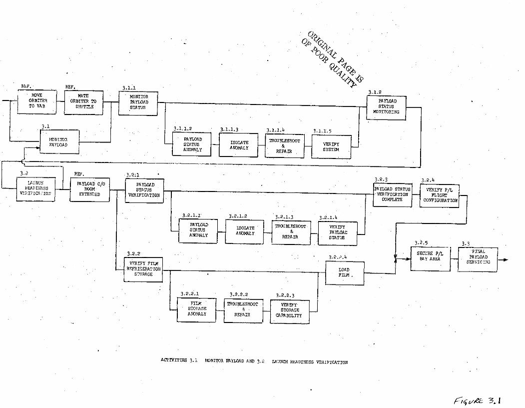
Scenario: Activity 3.0 Prelaunch and Launch Operations
All payload operations are covered in this activity from tow of orb ter
to VAB, mating orbiter in VAB, and preparations at PAD until liftoff. Dtring.
these periods this activity is concerned with payload monitoring, launch
readiness verification interface checks and final servicing prior to launch.
Block 3.1 Monitor Payload
After completion of payload final closeout in OPF tl is activity beg ns
and ends with MLP hard mounted at PAD. During this perioc the payload stttus,
LNZ/GN and power systems, are continously monitored. Th( monitoring re-
quirement exists through all activities up to shuttle lif off, so that th
payload integrity is not affected in any way in wl ich it ould affect its
performance during orbit.
Block 3.1.1 Monitor Payload Status
While in tow until MLP on hardmounts at PAD, the payload power syst m,
purge requirements and LI'loaded on board the payload experiments are mo.litored.
Facility Requirements
o Data Processing - via Orbiter Ground Linko Power - 11OVAC, 60Hz, 1KW/11OVAC, 400Hz, 30, 1KW
Support Requirements
o None
Block 3.1.1.2 Payload Status Anomally
During this activity an anomally coild be loss of power, which would result
in payload monitoring capabilities. The loss of GNZ purge which would affect
the payload status. Lastly, an LI problEm which could also affect the
payload status conditions.
Facility Requirements
o Data Processing - via Orbiter Ground Linko Power - ll0VAC, 60Hz, 1KW/llOVAC, 400Hz, 30, 1KW
Support Requirements
o None

Block 3.1.1.3 Isolate Anomally
The technician monitoring payload would have to ob;erve conditions,and try to isolate problem to a particular system
Facility Requirements
o Data Processing - via Orbiter Ground Link6 Power - 11OVAC, 60Hz, 1KW/11OVAC, 400Hz,.30, lIWSupport Requirements
o None
Block 3.1.1.4 Troubleshoot and Repair
When in tow, the technician/engineer will determine course of action
to troubleshoot after the MLP is hardmounted at PAD. At that time the
technician/engineer will proceed to troubleshoot and repair anomally.
Facility Requirements
o Data Processing - via Orbiter Ground Linko Power - 11OVAC, 60Hz, 1KW/llOVAC, 400Hz, 30, lKWSupport Requirements
o None
Block. 3.1.1.5 Verify System
Upon completion of repair of system, a verification test would be
prrformed to 1verify system functions as required to maint ain integrity of
payload.
Facility Requirementso Data Processing - via Orbiter Ground Linko Power - 11OVAC, 60HZ, 1KW/110VAC, 400Hz, 30, 1KWSupport Requirements
o None
Block 3.1.2 Payload Status Monitoring
A continous effort until liftoff to observe payload monitoring re-quirements function as required to maintain integrity of payload.
Block 3.1.2 (continued)'
Facility Requirements
o Data Processing - via Orbiter Ground Link
o Power - 11OVAC," 6 0Hz, 1KW/llOVAC, 400Hz, 30, 1KW
Support Requirements
o None
Block 3.2 Launch Readiness Verification
Begins with arrival at MLP a-t launch pad and MLP hard down on PAD
mounts, and ends with cabin hatch in closec position. During this period
the payload will be monitored, as in Activity 3.1, the launch readiness payload
verification checks will be performed, film loaded on orbiter for mission
and the LNZ system top-off performed, if required.
Block 3.2.1 Payload Status Verification
After arrival at PAD, access to the Orbiter payload Specialist Station
to perform an orbiter to payload interface verification. The verification
would check the operational capabilities of the controls and switches re-
quired to operate the payloads on-orbit.
Facility Requirements
o Data Processing - via Orbiter Ground Link
o Power - 11OVAC, 60HZ, lKW
o Monitoring - LPS
o Fluids - GNZ
Support Requirements
o None
Block 3.2.1.1 Payload Status Anomally
During verification an anomally could appear which could jeapardize
the mission. The anomally could be lack of control or switches in OPSS
for operation of payload/experiments, or the data processing/recording
system are inoperative due to interface problem or equipment failure.
Block 3.2.1.1 (continued)
Whatever the anomally we would pr, ceed to resolv: anomally prior to lifto Lf.
Facility Requirements
o Data Proces::ing - via Orbiter Ground Link
o Power - 11OVAC, 60 HZ, TBRT(KW)/11OVAC, 4OOHz, 30, TBD(KW)
o Ionitoring - LPS
o Fluids - GN2
Support Requirements
o None
Block 3.,21.2 Isolate Anomally
The technicians/engineers plrforming the verification checks would
isolate the anomally to either G )und Support Equipment, Payload/Experiment
or Orbiter Systems. After the an)mally has been isolated a typical approach
to resolution of problem is shown on Figure3.-j. The GSE/Payload/Experimet -
Off-Line maintenance would be performed by experimenter. Orbiter Systems
maintenance resolution would be KSC responsibility. Ti-t W1po zr6
Facility Requirements
o Data Processing - via Orbiter Ground Link
o Power - 110 VAC, 60 HZ, TBD(KW)/11OVAC,. 400Hz, 30, TBD(KW)
o Monitoring - LPS
o Fluids - GN2
Support Requirements 0 Q
o None
CRiEF. REF. 3.1.1
MOVE MATE MONITOR 3.1.2ORBITER ORBITER TO PAYLOAD PAYLOADTO VAB SHUTTLE STATUS STATUS
MONITORING
3.1 3.1.1.2 3.1.1.3 3.1.1.4 3.1.1.5
MONITOR PAYLOAD TROUBLESHOOTPAYLOAD STUS ISOLATE VERFY
SANOMALY ANOMALY REPAIR SYSTEM
3.2 RE 3.2.1-UNCH PAYLOAD C/O PAYLOADEADIN;SS PROOM STATUS PAYLOAD STATUS VERIFY P/LEV I'ICA TION EXTENDED VERIFICATION VEROFICATION FLIGT
COMPLETE CONFIGURATION
3.2.1.1 3.2.1.2 3.2.1.3 3.2.1.4
PAYLOAD SOATE TROUBLESHOOT VERIFY
ANOMALY A NOALAY & PAYLOADANOALY RREPAIR STATUS
3.2.5 3.3
3.2.2 SECURE P/L FINAL3.2.2 3.2.2.4 BAy AREA PAYLOADVERIFY FILM SEVICIN
. REFRIGERATION LOADSTORAGE I FILM .
3.2.2.1 3.2.2.2 3.2.2.3
FILM T ROUBLESHOOT i VERIFYSTORAGE & STORAGEANOMALY REPAIR CAPABILITY
ACTIVITIES 3.1 MONITOR PAYLOAD AND 3.2 LAUNCH READINESS VERIFICATION

Block 3.2.1.3 Troubleshoot and Repair
A typical approach is shown on Figure f/,
Facility Requirements
o Clean lab
o Calibration
o Radiological lab
o Machine lab
o Mech. lab
o Elect. lab
Support Requirements
o Transportation
o X-Ray
Block 3.2.1.4 Verify Payload Status - Off line
After the resolution of the payload/experiment/GSE anomally a verifi(ation
check would be made prior to installation in payload bay to show that is can
now support the defined performance requirements of the mission.
Facility Requirements
o Clean lab
o Calibration lab
o Radiological lab
o Machine lab
o Mech lab
o Elect. lab
Support Requirements
o GSE - TBD
o Special test equipment - TBD
o Transportation
Block 3.2.2 Verify Film Refrigeration Storage'
A verification check is performed to check refrigeraiion system for
proper cooling requirements prior to loading film on experiments in payload bay.
Facility Requirements
o Power - Orbiter power for refrigeration unit
Support Requirements
o None
Block 3.2.2.1 Film Storage Anomally
Return film to storage area until refrigerant anomally is resolved.
Facility Requirements
o Power - Orbiter power for refrigeration unit.
Support Requirements
o Transportation
Block 3.2.2.2 Troubleshoot and Repair
A typical approach is shown on Figure '8-~
Facility Requirements
o Mech. lab - if off line.
o Elect. lab - if off line.
o Power - Orbiter power for refrigeration unit, if at PAD
Support Requirements
o Transportation
Block 3.2.2.3 Verify Storage Capability
After resolution of refrigerant anomally verify the refrigeration
unit is ready for film storage.
Facility Requirements
o Power - Orbiter power for refrigeration unit
Block 3.2.2.3 Verify Storage Capability (cont.)
Support Requirements
o None
Block 3.2.2.4 Load Film
The verification check of the refrigeration unit was performed with
no problems, and if an anomally did occur it has since been resolved and
the film can now be placed on-board the orbiter.
Facility Requirements
o Power - Orbiter power for refrigeration unit
Support Requirements
o None
Block 3.2.3 Payload Status Verification Complete
The verification check was performed with no problems, and if an anomally
did occur it has since been resolved and the payload is ready for flight.
Facility Requirements
o Data Processing - via Orbiter Ground link
o Power - 110 VAC, 60 HZ, TBD(KW)/11OVAC, 400Hz, 30, TBD(KW)
o Monitoring -,LPS
o Fluids - GN2
Block 3.2.4 Verify Payload Flight Configuration
Prior to securing OBSS and payload bay a check is made to verify that
all experiments, controls, switches, etc. are in flight readiness configuration.
Facility Requirements
o Data Processing - via Orbiter Ground link
o Power - 110 AC, 60 HZ, TBD(KW)/11OVAC, 400Hz, 30, TBD(KW)
o Monitoring - LPS
o Fluids - GN2

Block 3.2.4 (cont.)
Support Requirements
o None
Block 3.2.5 Secure Payload Bay Area
Secure all PPE used in verification checks between OPSS and payload.
Facility Requirements
o None
Support Requirements
.o TBD
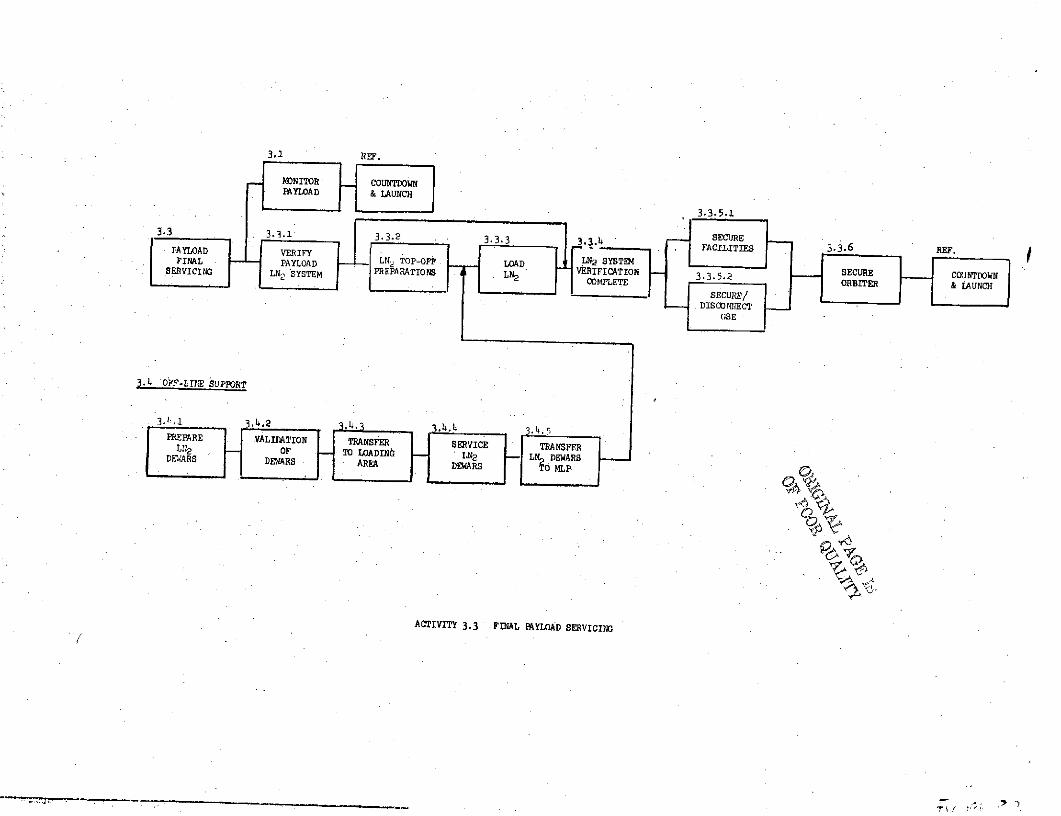
Block 3.3 Payload Final Servicing
During this period the payload will be monitored, as in Activity 3-1
through liftoff. The payload final servicing will start 20-6 hrs. when access
is required to payload bay through the payload changeout room. At this time
the LN2 system will be monitored to determine if LN? top-off is required.
In parallel off-line support the LN2 dewars will be prepared for servicing,
so as to be ready if LN2 top-off is required. After top-off, the payload/
orbiter will be secured and the orbiter shuttle will proceed with countdown
and liftoff.
Block 3.3.1 Verify Payload LN2 system
Access is required through payload changeout room to payload bay at
TO-6 hours to monitor LN9 system to determine if LN2 system needs top-off.
Facility Requirements
o Fluids - LN2 , GN2
o Power - 110 VAC, 60 HZ, TBD(KW)/I1OVAC, 400Hz, 30, TBD(KW)
o Data Processing - via Orbiter Ground link
o Monitoring - LPS
Support Requirements
o None
3.3.5.1
3.3 3.3.1 3.3.2 3.3.3 3,3.4 SECUREAAYLOAD VERIFY FACILITIES 3.3.6RE
FINAL PAYLOAD LN OP AD LN2 SYSTEMSEVICIN LN SYSTEM PREPARATIONS LN VERIFICATION SECURECOMPLETE ORBITER & AUCH
SECURE/DISCONNECT
GSE
3.4 OF-LINE SUPPORT
3J.1l
3.4.2 3.h.3
PREPARE VALIDATION TRANSFER SERVICE TRANSFERR oF - T- O LODING LN2 - L DEWARSDTITARS DEWARS 3AREA DEARS d LP N
ACTIVITY 3.3 FINAL PAYLOAD SERVICING
(~ );
Block ..3.2 LN2 Top-Off Preparations
Install/connect GSE servicing equipment to payload in preparation for
loading LN2 .
Facility Requirements
o Payload changeout room
o Power - TBD
Support Requirements
o None
Block 3.3.3 Load LN2
With the arrival of the LN2 dewars, connect the dewars to servicing
GSE and proceed to load LN2.
Facility Requirements
o Monitoring - LPS
o Data Processing - via Orbiter Ground link
o Power - 110 VAC, 60 HZ, TBD(KW)
o Fluids - LN2
Support Requirements
o Safety
Block 3.3.4 LN2 System Verification Complete
The LN2 System monitoring check was performed, and if top-off was required
the LN2 system is now ready to perform its mission in orbit.
Facility Requirements
o Monitoring - LPS
o Data Processing - via Orbiter Ground link
o Power - 110 VAC, 60 HZ, TBD(KW)
Support Requirements
o None
Block 3.3.5.1 Secure Facilities
Secure all facilities on MLP in support of payload monitoring, verification
checks and servicing.
Facility Requirements
o None
Support Requirements
o None
Block 3.3.5.2 Secure/Disconnect GSE
Secure/disconnect all GSE on MLP, Parload Changeout Room, used in support
of payload monitoring, verification checks and servicing.
Facility Requirements
o None
Support Requirements
o Transportation -TBD
o Safety
Block 3.3.6 Secure Orbiter
Payload bay, payload/experiments are now completely secured and Launch
Operations can proceed toward countdown and lift-off.
Facility Requirements
o None
Support Requirements
o None
Block 3.4 Off-Line Support
Off-line Support is any activity requ ired for support of verification,
servicing, monitoring, etc. that will be used to support the processing of the
payload through Launch Operations.
Block 3.4.1 Prep. LN2 Dewars
The preparations is an off-line activity for top-off of LN on payload
at TO-6 hours.

Block 3.4.1 (cont.)
Includes disassembly/assembly of dewars for cleaning, calibration and
proofing of hoses.
Facility Requirements
o 'Mech. lab with laminar flow bench
o Clean lab
o Calibration lab
Support Requirements
o Transportation - TBD
Block 3.4.2 Validation of Dewars
Functional test of dewars prior to servicing.
Facility Requirements
o Mech. lab
o Power - TBD
o Fluids -GN 2 , LN2
Support Requirements
o None
Block 3..3 Transferring dewars to area for LNZ loading
Facility Requirements
o None
Support Requirements
o Transportation - TBD
Block 3.4.4 Service LNO Dewars
Configure LN2 dewars, load, and verify dewars are re:Ldy to support
top-off of payload experiment.
Block 3.4.4 (cont.)
Facility Requirements
o Fluids - LN2
o Power - TBD
Support Requirements
o None
Block 3.4.5 Transfer LN2 Dewars to MLP
Upon completion of servicing transfer LN2 dewars to MLP to support top-off
of payload/experiment.
Facility Requirements
o None
Support Requirements
o Transportation - TBD
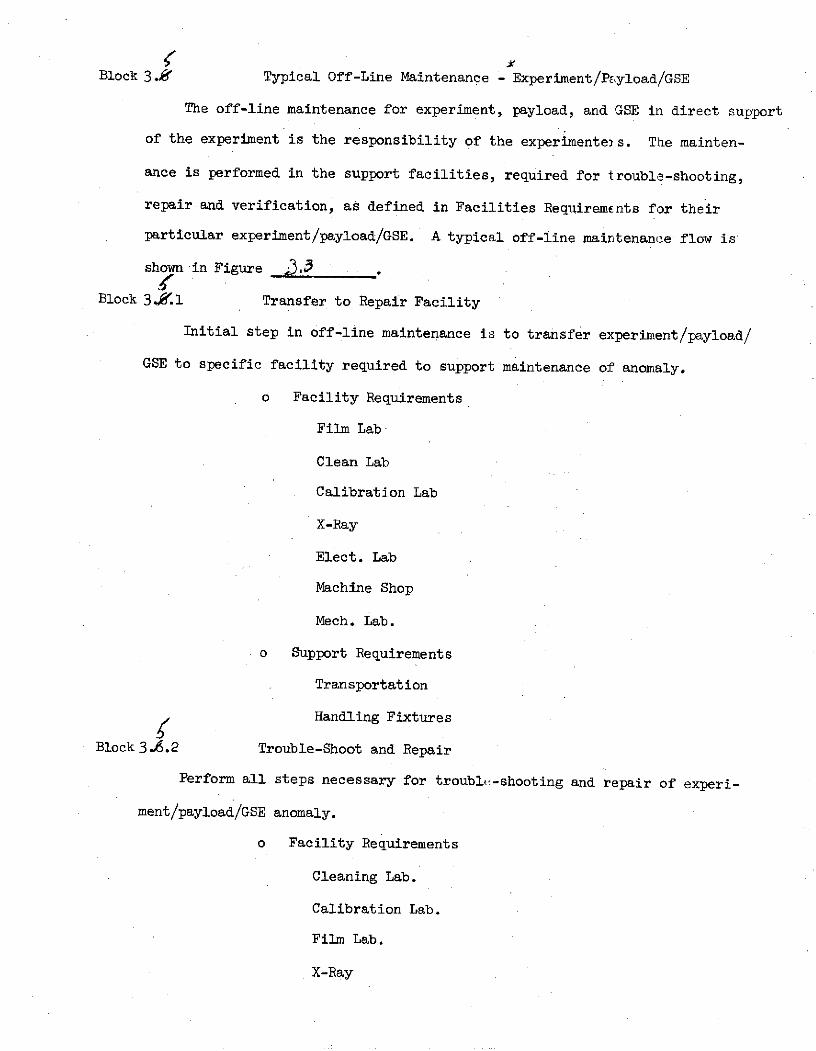
Block 3.4f Typical Off-Line Maintenance - Experiment/PE.yload/GSE
The off-line maintenance for experiment, payload, and GSE in direct support
of the experiment is the responsibility of the experimente2s. The mainten-
ance is performed in the support facilities, required for trouble-shooting,
repair and verification, as defined in Facilities Requirements for their
particular experiment/payload/GSE. A typical off-line maintenance flow is
shown in Figure 2.3
Block 3..1 Transfer to Repair Facility
Initial step in off-line maintenance is to transfer experiment/payload/
GSE to specific facility required to support maintenance of anomaly.
o Facility Requirements
Film Lab
Clean Lab
Calibration Lab
X-Ray
Elect. Lab
Machine Shop
Mech. Lab.
o Support Requirements
Transportation
SHandling Fixtures
Block 3.6.2 Trouble-Shoot and Repair
Perform all steps necessary for troubl-shooting and repair of experi-
ment/payload/GSE anomaly.
o Facility Requirements
Cleaning Lab.
Calibration Lab.
Film Lab.
X-Ray

3.5 3.5.:1 3.5.2 3.5.3 3.5.4 3.5.55 3.1
Pi EARE ( RERN TO)TRANSFER R 7M LII M)IOOFF-LINE TOBLESHOOT FOIDTEMR TRANSFFRSSE/ OIOTO REPAIR TXEIET I ALA
L gouIT P/L BY I CONFIGURATION
TYPICAL EXPERIMENT/PAYLOAD/GSE - OFF-LINE MAINTENANCE FLOW
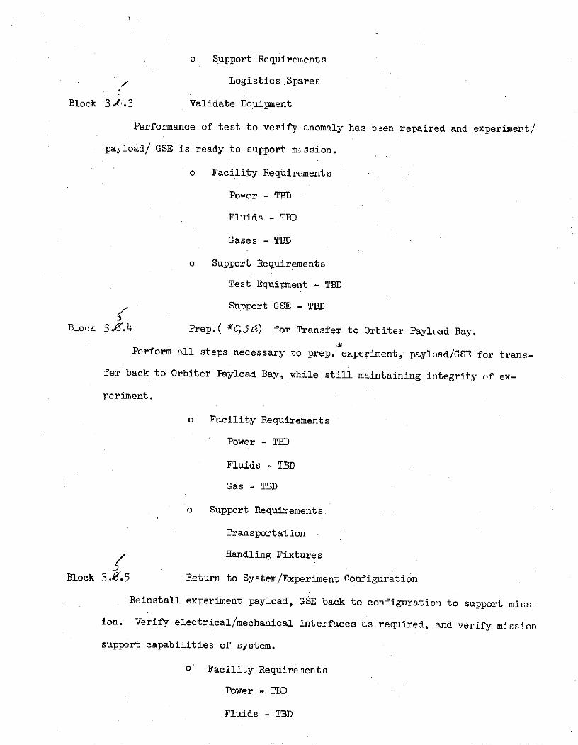
o Support Requirements
- Logistics Spares
Block 3.6.3 Validate Equipment
Performance of test to verify anomaly has been repaired and experiment/
payload/ GSE is ready to support mission.
o Facility Requirements
Power - TBD
Fluids - TBD
Gases - TBD
o Support Requirements
Test Equipment - TBD
7 Support GSE - TBD
Blo-k 3.~'.4 Prep.( 0J5) for Transfer to Orbiter Payl(ad Bay.
Perform all steps necessary to prep. experiment, payload/GSE for trans-
fer back to Orbiter Payload Bay, while still maintaining integrity of ex-
periment.
o Facility Requirements
Power - TBD
Fluids - TBD
Gas - TBD
o Support Requirements
Transportation
Handling Fixtures
Block 3. .5 Return to System/Experiment Configuration
Reinstall experiment payload, GSE back to configuration to support miss-
ion. Verify electrical/mechanical interfaces as required, and verify mission
support capabilities of system.
o Facility Require nents
Power - TBD
Fluids - TBD
Gas - TBD
Data Processing
Monitoring - LPS
o Support Requirements
TBD
Block 3 Wp - Payload/Orbiter - Maintenance .ft.
The Orbiter Support System for Payloads are Orbiter (KSC) responsib-
ility. If an anomaly occurs between the interfaces, such as in the Data
Processing System or Environmental System, the appropriate Orbiter (KSC)
representative would be notified and KSC would proceed with resolving an-
omaly. After resolution, interfaces would be verified to determine if
now payload is ready to support its mission in orbit.
o Facility Requirements
KSC Responsibility
o Support Requirements
KSC Responsibility
Scenario - Activity
Block 4.0 Post Landing Operations
With the Orbiter hard mounted in the OPF, the Orbitcr Support Systems
are switched to facility services and preparation for safing and removal of
payload elements begins. Safing completed, the time critical items are removed,
and the GSE processing for removal of payload doors and payload proceed until
payload is securely mounted on transporter and is transported to the Payload
Post-Mission Processing Area.
Block L.1 Switch to Facility Services and Safe Payload
The Orbiter Support Systems are switched to facility services; such *ts,
power, cooling and instrumentation. Purge and Dry Payload elements (as
applicable) commences until payload is environmentally safe for personnel access.
The switch over to Payload Ground Monitoring, if applicab!e, is also veri'ied
during this activity.
Block 4.1.1 Payload Support System Verification
The payload bay area has been pruged and the change over to faciliti s for
power, cooling, instrumentation for grount monitoring has been completed tnd
verified operational.
Facility Requirements
Power - llOVAC, 60Hz, 2KW
Fluids - GN2Support Requirements
None.
Block 4.1.2 Payload Environment Safe
A verification by safety that the payload area is environmental safe for
personnel access.
Facility Requirements
Power - llOVAC, 60Hz, 2KW
Fluids - GN2Support Requirements
Safety.
Llock i.2 Remove Time Critical Flight Experiments
The payload bay area safe for access, the experimenters can perform the
-asks necessary for the removal of time critical flight (experiments; such as,
film.
Block 4.2.1 Place Items in Applicable Containers/Carriers
Upon access to payload, the experimenters remove the time critical flight
experiments; such as, film, and place them in applicable containers/carriers.
Facility Requirements
Power - 110 VAC, 6 0Hz, 2KW
Support Requirements
None.
Block 4.2.2 Remove from Orbiter Payload Bay
The Time .Critical Flight Experiments are ready for removal from Orbiter
Payload Bay, and are transferred to the appropriate processing area.
Facility Requirements
Power - 110 VAC, 60Hz, 2KW
Support Requirements
Transportation
Dark Room
Block 4.3 Open Payload Bay Doors and Install Payload GSE
After the thermal protection system, the Payload Bay Doors are removed
and the manipulator arm deployed, the experimenter is responsible for installatioi
of payload bay access stands.
Block 4.3.1 Install Payload Bay Access Stands
The experimenter install payload access stands, as required for removal
of payload from Orbiter Payload Bay.
Facility Requirements
Power - 110 VAC, 60Hz, 2KW
Support Requirements
None
1-lock 1..4 Remove Payload
The removal of Payload includes all the tasks; such as, attaching payload
handling GSE, demating of the Payload/Orbiter interfaces, the removal of access
stands, and finally the removal from payload bay and placement on payload
transporter/handling fixture.
Block 4.4.1 Attach Payload Handling GSE
The Payload Handling GSE; such as, slings are now moved into place and
connected to lifting points on payload.
Facility Requirements
Power - 110 VAC, 60Hz, 2KW
Crane - 15000 lbs. capability
Support Requirements
None.
Block 4.4.2 Demate Payload/Orbiter Interfaces
The Payload/Orbiter Interfaces are disconnected and the payload is
inspected for approval for removal from Orbiter.
Facility Requirements
Power - 110 VAC, 60Hz, 2KW
Crane - 15000 lbs.
Support Requirements
None.
Block 4.4.3 Remove Access Stands from Payload Bay
The experimenters remove the access stands in order to clear the payload
bay area for removal of payload.
Facility Requirements
None
Support Requirements
None.
Block 4.4.4 Remove Payload from Payload Bay
The Payload is lifted from the payload bay and installed/mounted on the
payload transporter/handling fixture.
Facility Requirements
Power - 110 VAC, 60Hz, 2KW
Crane - 15,000 lbs.
Support Requirements
Safety.
Block 4.5 Move Payload to Post Mission Processing Area
After payload is installed/mounted on transporter verify payload monitoring
system is operating, if applicalbe, and p yload is secure and proceed with
transfer to Post Mission Processing Area.
Block 4.5.1 Verify Payload Secure on Transp rter
Experimenter verifies payload monito ing system is operational, 3nd
payload is securely mounted on transportejr.
Facility Requirements
Crane - 15,000 lbs.
Support Requirements
None.
Block 4.5.2 Move Payload to Post Mission Processing Area
With payload secure in transporter, proceed to Post Mission Processing
Area.
Facility Requirements
None.
Support Requirenents
Transportation - Tractor
Security
Safety
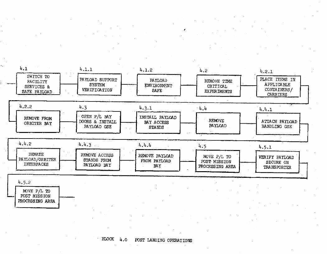
4.1 4.1.1 4.1.2 4.2 4.2.1SWITCH TO CE ITEMS INFACILITY PAYLOAD SUPPORT PAYLOAD REMOVE TIM APPLACE ITEMS INFACILITY
SERVICES& SYSTEM E NVIRONMENT -CRITICAL "APPLICABLESAFE PAYLOAD VERIFICATION SAFE EXPERIMENTS CONTAINERS/SEj
C L CARRIERS
4.2.2 4.3 4.3.1 4.4 4.4.1
REMOVE FROM OPEN P/L BAY INSTALL PAYLOADORBITER BAY - DOORS & INSTALL BAY ACCESS REMOVE ATTACH PAYLOAD
PAYLOAD GSE STANDS PAYLOAD HANDLING GSE
4.4.2 4.4.3 4.4.4 4.5 4.5.1
DEMATE REMOVE ACCESS REMOVE PAYLOAD MOVE P/L TO VERIFY PAYLOADPAYLOAD/ORBITER STANDS FROM FROM PAYLOAD POST MISSION SECURE ON.INTERFACES PAYLOAD BAY BAY PROCESSING AREA TRANSPORTER
4.5.2
MOVE P/L TO- POST MISSION
PROCESSING AREA
BLOCK 4.0 POST LANDING OPERATIONS

Block 5.0 Post Mission Processing - Mission #13
The activities contained wLthin this functional block defines the
processing required following flight and prepares the various payload
elements for return to their post mission sites. Figure 2.5-1 graphic-
ally depicts this flow.
The vollowing assumptions were made in defining this flow:
o Vehicle has been safed and verified.
o All pressures have been vented to nominal values.
o All lines have been I1rged, padded, and capped.
o All exposed electtical connectors have been capped.
o All other activity in Functional Block 4.0 has been completed.
Block 5.1 Inspect Payload
Conditions The pallets with their experiments have been delivered to
the Premission Processing Facility and wiped down in the airlock.
Block 5.1.1 Position payload and access GSE in the proper area.
Block 5.1.2 Remove all protective covers and/or panels to gain visual
access to all payload elements.
Block 5.1.3 Visually inspect all payload elements for physical damage
and document the discrepancy.
Block 5.1.4 Remove any remaining flight data and deliver to the proper
agency.
Block 5.1.5 Clean payload elements as required.
Support Requirements for Functional Block 5.1
Facilities
Floor space,2700 sq. ft. (90 x 30)
O/H crane 4 ton capacity
GN
Ground Support Equipment
Access stand, set
GN2 regulating unit

o0
T~TG 2.5-1 POST WSZn9 VF4CSM MISN # 03
7/5.2 52.1 5.2.2523
2D4)VEts VISUAL EHMW CL DDBRTE M~LLET PQsi~rIos P/L A=TA'" 'P/L & ,-CEMINPET P.U/AfII SECTION iom & GSE FOR EAESLIG Sz'OFLIGHT DAT tE-ATE GSE
545415.4.3 5.4i.4 5.4~.5 .5-L 6
OR OR OR ON& AT S TEELJ AFT H
5.6a1 5.6.2 5.6.3 .7 .. 15.7.2 5.7.3 5.T.4j
Cli!~ A CE GSEM-1.ECT
RAN-SPA1 IE'C B AC~s/ SETS & Fnlm%~
5.8 5.1 . .. 25835.8.4
5.9 5.9. 59- 5.9-3 5.-'59.5
FO~~A A~TI!*
Block 5.1.5 (Continued)
Ground Support Equipment (Continued)
Handling equipment, covers/panels
Support
Crane operator
Personnel
Technicians
Q.C.
Safety
Engineers
Logistics
Procedures
Block 5.3 Demate Pallet Sections
Conditions Post mission cleaning and inspection has been completed.
Block 5.3.1 Position pallets and GSE for demating.
Block 5.3.2 Attach handling GSE to pallet #1
Note: Pallet #1 contains the Igloo and forward utility bridge (cant-
ilevered from the front face). Utilize caution in demating from the other
pallet sections.
Block 5.3.2.1 Demate all interface connections between pallets #1 and #2.
Cap all lines and plugs.
Block 5.3.3 Demate pallet #1 from pallet #2.
Repeat steps 5.3.1 through 5.3.3 for remaining pallet sections.
Note: Exact procedures of the demate operation will depend on detail
design of the transporter used to move the payload fro.a the OPFF to the PPF.
As an example, the transporter may be modular, with each pallet section on
its own cradle/dolly. If this is the case, the demate operation would in-
volve merely horizontal movement of the pallet/dolly to affect separation.
Support Requirements for Functional Block 5.3
Same as 5.1
Block 5.5 Transport Pallet Sections to CIS
Conditions Pallets have been demated and are ready for tiansport.
Block 5.5.1 Secure pallet section(s) on transporter(s).
Block 5.5.2 Install supporting transporter GSE.
Block 5.5.3 Install cover(s), purge and establish proper atmosphere
for transport.
Block 5.5.4 Move transporter(s) with pallet section(s) to shipping area.
Block 5.5.5 Load on transport vehicle tie down and secure. Verify all
monitoring devices operational.
Support Requirements for Functional Block 5.5
Same as 5.1 plus transport covers, tow vehicle and operator.
Shipping area TBD

DEDICATED SOLAR SORTIE MISSION (DSSM)
SO-01-S
Difference Between
Launch Site Facility Requirements Data Sheet (Functional)
(Revision A - dated 8/31 74)
and
GAC Data
The differences in launch site requirements are included in the following
pages. The Data Sheet information is shown in parenthesis and followed by GAC
data and logic basis. Requirements solely generated by GAC and not reflected
in the Data Sheets have not been duplicated.
Block 1.0 Payload Premission Processing
Block 1.8 Receiving and Inspection
A. Experiment/Payload Area Requirements
Length(ft) Width(ft) Min Height(ft)
(45) (15) (6o)
o 72 ft. long (CBS - 60 ft., end clearance 6 ft. both ends), 41 ft.
wide (shipping container - 11 ft., CBS - 18 ft. side clearance
6 ft. both sides), height 30 ft. (trailer and shipping container -
16 ft., pallet segment and clearance - 14 ft.).
TEMP (oK)
(290 . 4) (620 ± 8)
D Level B data contains the following:
- Data Sheet #S-23; Receiving Facility temperature 290 + 4K.
- Data Sheets S-24a and 24b - Groind Environmental Limits -
non-operating minimum of 2550K (O°F) and maximum of 325 K (120 0F).
Assuming the receiving and inspection area of the PPF will be routinely
heated and air conditioned, the 290 . 4K requirement is deleted, and
the conclusion reached that the DSSM imposes no temperature requirements
for the receive and inspect function.
RELATIVE HUMIDITY (%)
(30 to 60)
o Level B data contains the following:
Data Sheet #S-23; Receiving Facility relative humidity 30 to 60%.
- Data Sheets #S-24a and S-24b; non-operating maximum relative
humidity as 25%.
These requirements involve high cost moisture removal equipment. It
is understood that humidity is maintained about 50% (±10) in the high
bay area of the O&C Building.
It is recommended that the DSSM relative humidity requirement be
investigated, with the objective to raise it to the 50%(t10) level.
1.8 (continued)
B. Fluids
MEDIA (GN2 )
PRESS (PSIG) (3500)
FLOW RATE (10 c.f.m.)
TOTAL VOLUME (7200 ft.3 )
TEMP (oK) (290 ± 4)
CLEANLINESS SPEC ( < 5000)
o Level B data lists the following:
Data Sheet #S-9 (In-flight, non-operating) - Equipments 001, 002,
and 003 require nitrogen for film; 004, 005, 020, 007, 008, and
009 require GN2 for purge on pad during entry, landing, and
post landing. Equipment 015 required GN2 , purpose unstated.
Data Sheet #S-lOa and b (In-flight, operating) - No requirements
for nitrogen.
Data Sheet #S-lla and b (In-flight Contamination Control Criteria) -
generally, reflects same data as Data Sheet #S-9 above.
Data Sheet #S-22 (Launch/Land Support Requirements) - for Launch
Pad/Lift-off, GN2 purge line 2 cu. m/hr (about 1.18 ft. 3/min)
required, equipment to be provided by Pad.
Data Sheet #S-23 (Ground Facility Requirements) - for the Supply
Shipping and Receiving Facility at the launch site GN2 is listed
as a utility requirement.
It is felt that the above Level B data is too broad to definea
specific fluid requirement for Block 1.8 - Receiving and
Inspection - activities. It is recommended that the fluid
requirement be listed a TBD at this time, and effort be made to
obtain definitive purging requirements of the instruments during
transportation, when in storage in their shipping containers, and
when removed from their shippin containers in a 100K clean

1.8
B. Fluids (continued)
environment (high bay area of PPF). When these instruments
requirements are adequately defined, the launch site support and
facility requirements for fluids for DSSM may be determined.
C. Special Handling
(Crane and Transporter - 17 ton)
o Crane capacity of 10,000 lbs. The Study processes individual pallets
upon which are mounted the experiments. The heaviest pallet contains
experiments 002, 007, and 008. The weight of the oallet plus its
shipping container is estimated to be about 6,500 Lbs.
o For a "Transporter", the Study uses the concept of a Cargo Bay
Simulator which serves the purpose of transporting the DSSM at the 3m
launch site.
D. Payload Peculiar Equipment
(400 sq. ft.)
o 20 ft. long, 16 ft. wide, 4 ft. higI which provides space for two of
five GSE racks estimated to support the DSSM foractivities in the PPF.
The receive/inspection function is considered by the Study to be performed
in series; therefore, areafor all five GSE racks at one time is not
required.
Block 1.11 Mate Pallet, Reassemble and Checkout
A. Experiment/Payload Area Requirements
(Data same as Block 1.8 above)
o Block 1.11 is defined as mating pallt sections with liaison pallet
which the Study considered not applicable to the DSSM flight.
Block 1.10 in Study verifies individual pallet interfaces, installs
pallets into Cargo Bay Simulator, ani verifies end-to-end installed
pallet interfaces in preparation of aext activity (Block 1.12 - Connect
Orbiter Simulator). Study Block 1.1) is assumed to be same as Block 1.11
above for the purposes of Data Sheet evaluation.
Block 1.11
A. Experiment/Payload Area Requireme its (continued)
o PPF Checkout Area
- 80 ft. long, 35 ft. wide, 39 ft. high for Cargo Bay Simulator,
work stands, and clearances.
- 15.ft. long, 10 ft. wide, 18 ft. high for pallet segments.
- 12 ft. long, 8 ft. wide, 4 ft. high for DSSM GSE.
o For TEMP(OK), RELATIVE HUMIDITY(-%), and CLEANLINESS CLASS:
Refer to paragraphs in Block 1.8 above.
B. Fluids
MEDIA (LN 2 )
PRESS(PSIG) (30)
FLOW RATE (1 lb/min)
TOTAL VOL (220 lbs.)
CLEANLINESS N/A
o Level B data lists the following:
- Data Sheet #S-25 (Payload Safety Analysis) shows experiments
011, 013, and 014 use cryogenic nitrogen.
- Data Sheet #S-24a (Ground Environmental Limits) shows non-operating
min/max temperature of these three experiments to be TBD, with
operating temperature being min = 2920K(64°F) and max = 2960 K(720 F).
- Data Sheet #S-23 (Ground Facility Requirements) shows that at the
launch site at the Payload Operations and Checkout Facility,
utility requirements include LN2 .
The Study lists no LN2 requirement for the checkout function. The logic
follows:
Interface verification is performed without ooerating the
instruments, using GSE to simulate instrument sensor outputs as
required.
Level B data is too general to establish a firm LN2 support/facility
requirement.
Block 1.11
C. AC Power
VOLTS (AC) ERTZ PHASE POWER(KW)
(115) (60) (Single) (15.0)
(110) (400) (3) (3.0)o Level B data lists the following:
Data Sheets #S-8a and 8b (Experiment equipment - Power and Data)
shows VAQ = 28, 400 cycles, total standlpower - 90W, operating
power = 70.%, peak power = 1217 W. These power data are based
upon Data Sheet #S-15, the Payload Operational Time Line, MissionDay #3.
The Study power requirements are TBD at this time. The logic is:
o Interface verification is performed without operating the
instruments, using GSE to simulate instrument sensor
outputs as required.
o DSSM GSE for interface verification tests is not define(,
and it is felt that estimated GSE is too general to develop
firm launch site electrical support requirements.
Block 1.12 Connect Orbiter Simulator
A. Experiment/Payload Area Requirements
LENGTH (ft) WIDTH (ft) MIN HEIGHT (ft)(45) (15) (19)
o 72 ft. long (CBS - 60 ft.; Orbiter Simulator = 12 ft.), 27 ft. wide(CBS = 15; workstands = 6 ft. each side), 18 ft. high (CBS =.18 ft.).
o For TEMP(0K), RELATIVE HUMIDITY ),and CLEANLINESS CLASS: Refer
to paragraphs in Block 1.8 above.
B. Fluids
(Data Sheet requirements same as paragraph Block 1.8B above.)
o GN2 requirement is TBD at this time. See paragraph Block 1.8B above
for logic.
Block 1.12.1 Load and Verify Flight Software
(Data Sheet requirements are VAC=115, Hertz=60, Phase=single,
Power(KW)=15, and 600 sq. ft. for Payload Peculiar Equipment.)
o The Study assumes that flight software verification would be performed
by launch site personnel, and therefore no support facility requirement
were developed for this activity.
Block 1.13 Final Integrated Systems Test
A. Experiment/Payload Area Requirements
(Data Sheet information same as paragraph Block 1.12A above.)
o Study data same as Block 1.12A above.
B. Fluids
(Data Sheet information same as paragraph Block 1.8B above.)
o Study data same as Block 1.8B above.
C. AC Power
(Data Sheet information same as paragraph Block 1.11C above.)
o Study data same as Block 1.11C above.
D. Payload Peculiar Equipment
(6o0 sq. ft.)
o Study results have no requirements, based upon the assumption that,
for the Final Integrated Systems Test, the DSSM GSE would be integrated
in the Orbiter Simulator or located on the CBS workstands.
Block 1.14 Service Non-time Critical Items
A. Experiment/Payload Area Requirements
(Data Sheet information same as Blocks 1.11 through 1.13)
B. Fluids
(Data Sheet lists requirements for GN2 and LN2 )
C. AC Power
(Data Sheet lists requirement for 115VAC.)

Block 1.14 (continued)
D. Payload Peculiar Equipment
(Data Sheet lists area requirements for 600 sq. ft.)
o Level B data does not define any non-time critical service
requirements. Study lists candidate as GN2 supply for instrument
purging, and lists the GN2 and electrical power to support the
purge as TBD.
o The LN2 requirement is considered time-dependent, and its service
should be deleted from Block 1.14 requirements.
Block 1.16 Weight and C.G.
(Data Sheet information contains requirements for area, fluids, power,
and special handling.)
o The Study baseline Sortie Payload Functional Flow does not contain
a Weight and C.G. activity block, therefore, no requirements for
this activity were considered in the Study. Hcwever, if the Weight
and C.G. test is to be performed, it is felt that the test wouLd be
conducted by launch site personnel, and would rot involve experiment-
related requirements.
Block 1.17 Move to OPF
(Data Sheet information similar to Block 1.8 except height reduced from
60 to 19 ft., GN2 supplied by portable source, and 115VAC required.)
o Study requirements are:
A. Area
The Study uses the concept of a Cargo Bay Simulator (CBS) which is
60 ft. in length vice 45 ft. length of Data Sheet.
B. Fluids
Study indicates a supply of GN2 is a candidate requirement. See
paragraph Block 1.8B above.
I lock 1.17 (continued)
C. AC Power
Study does not identify a requirement for 115VAC during the move
from PPF to OPF. Level B Data, Data Sheet #S-2," (Launch/Land
Support Requirements) lists a monitoring requirement to start 48 hours
prior to launch via Orbiter ground link; howevei-, this requirement
would not appear to be valid for Block 1.17 activity.
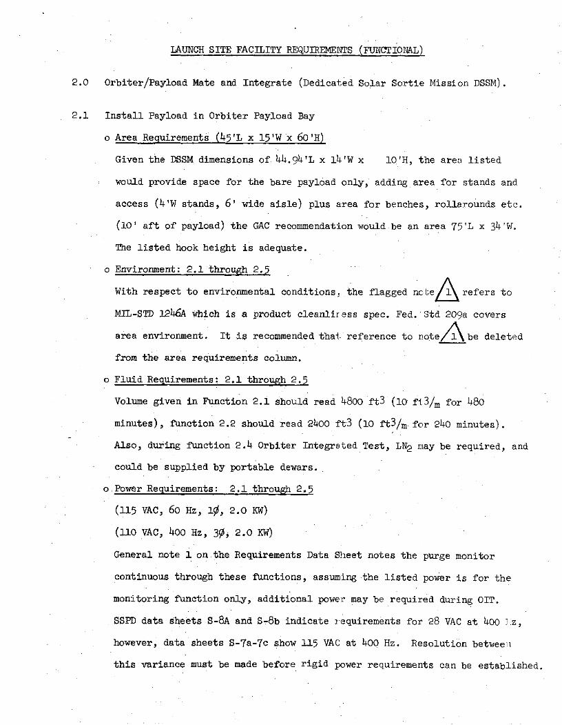
LAUNCH SITE FACILITY REQUIREMENTS (FUNCTIONAL)
2.0 Orbiter/Payload Mate and Integrate (Dedicated Solar Sortie Mission DSSM).
2.1 Install Payload in Orbiter Payload Bay
o Area Requirements (45'L x 15'W x 60'H)
Given the DSSM dimensions of 44.94'L x 14'W x 10'H, the area listed
would provide space for the bare payload only, adding area for stands and
access (4'W stands, 6' wide aisle) plus area for benches, rollarounds etc.
(10' aft of payload) the GAC recommendation would be an area 75'L x 34'W.
The listed hook height is adequate.
o Environment: 2.1 through 2.5
With respect to environmental conditions, the flagged no e refers to
MIL-STD 1246A which is a product cleanliress spec. Fed. Std 209a covers
area environment. It is recommended that reference to note/\be deleted
from the area requirements column.
o Fluid Requirements: 2.1 through 2.5
Volume given in Function 2.1 should read 4800 ft3 (lo0 ft 3 /m for 480
minutes), function 2.2 should read 2400 ft3 (10 ft3/m for 240 minutes).
Also, during function 2.4 Orbiter Integrated Test, LN2 may be required, and
could be supplied by portable dewars.
o Power Requirements: 2.1 through 2.5
(115 VAC, 60 Hz, 10, 2.0 KW)
(110 VAC, 400 Hz, 30, 2.0 KW)
General note 1 on the Requirements Data Sheet notes the purge monitor
continuous through these functions, assuming the listed power is for the
monitoring function only, additional power may be required during OIT.
SSPD data sheets S-8A and S-8b indicate requirements for 28 VAC at 400 > z,
however, data sheets S-7a-7c show 115 VAC at 400 Hz. Resolution betweein
this variance must be made before rigid power requirements can be established.
2.1 (Continued)
o Special Handling: 2.1
(Crane, Transporter 17 ton capability)
Level B data lists the payload weight at 5619 kg, the ERNO Space Lab
description (June 1974) gives maximum pallet weight at 4670 kg. Total weight
would be 5619 + 4670 = 10,289 kg or 22,687 pounds. A 12 ton crane would
be adequate.
There are no other changes recommended.
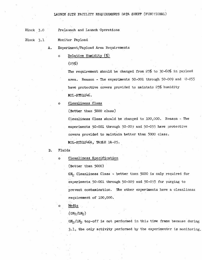
LAUNCH SITE FACILITY REQUIREMENTS DATA SHEET (FUNC PIONAL)
Block 3.0 Prelaunch and Launch Operations
Block 3.1 Monitor Payload
A. Experiment/Payload Area Requirements
o Relative Humidity ($)
(25%)
The requirement should be changed from 25% to 30-600 in payload
area. Reason - The experiments 50,-001 through 50-009 and ;0-055
have protective covers provided to maintain 25% humidity
MIL-STD1246.
o Cleanliness Class
(Better than 5000 class)
Cleanliness Class should be changed to 100,000. Reason - The
experiments 50-001 through 50-009 and 50-055 have protective
covers provided to maintain better than 5000 class.
MIL-STD1246A, TABLE 1A-25.
B. Fluids
o Cleanliness Specification
(Better than 5000)
GN2 Cleanliness Class - better than 5000 is only required for
experiments 50-001 through 50-009 and 50-055 for purging to
prevent contamination. The other experiments have a cleanliness
requirement of 100,000.
o Media
(GN2 /LN2 )
:GN2 /LN 2 top-off is not -performed in this time frame because during
3.1, the only activity performed by the experimenter is monitoring.
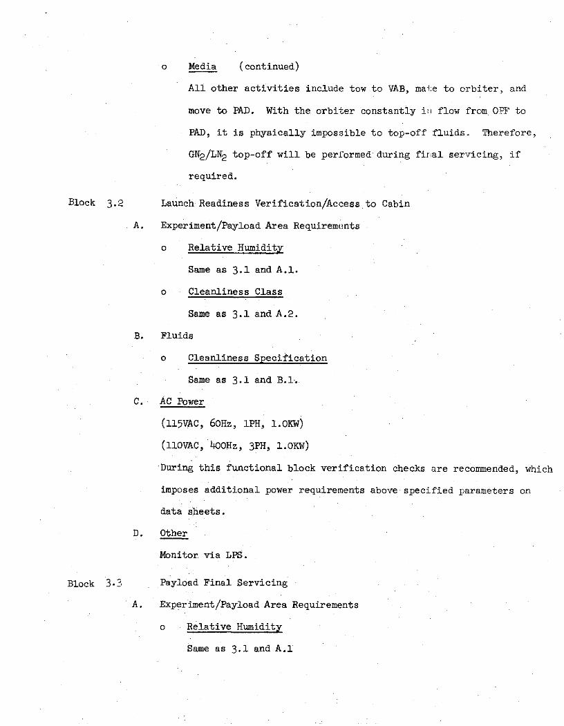
o Media (continued)
All other activities include tow to VAB, mate to orbiter, and
move to PAD. With the orbiter constantly in flow from OPF to
PAD, it is physically impossible to top-off fluids. Therefore,
GN2 /LN 2 top-off will be performed during final servicing, if
required.
Block 3.2 Launch Readiness Verification/Access to Cabin
A. Experiment/Payload Area Requirements
o Relative Humidity
Same as 3.1 and A.1.
o Cleanliness Class
Same as 3.1 and A.2.
B. Fluids
o Cleanliness Specification
Same as 3.1 and B.1.
C. AC Power
(ll5VAC, 60Hz, IPH, L.OKW)
(11OVAC, 400Hz, 3PH, 1.OKW)
During this functional block verification checks are recommended, which
imposes additional power requirements above specified parameters on
data sheets.
D. Other
Monitor via LPS.
Block 3.3 Payload Final Servicing
A. Experiment/Payload Area Requirements
o Relative Humidity
Same as 3.1 and A.1
o Cleanliness Class
Same as 3.1.A.2.
B. Fluids
o Cleanliness Specification
Same as 3.1.B.1.
C. AC Power
(ll5VAC, 60Hz, IPH, 1.OKW)
(11OVAC, 4O0Hz, 3PH, 1.OKW)
For top-off of LN2 , additional power is required for support/operation
of GSE. At this time, the additional power parameters are not known.
The power requirements are presently (TBD).
LAUNCH SITE FACILITY REQUIREMENTS (DEDICATED SOLAR SORTIE MISSION)
Block 4.0 Post Landing Operations
No data changes until function:
Block 4 .4 Remove Payload
o Area Requirements: (45'long x 15'wide x 60'high)
Using the same logic applied to function 2.0, GAC describes the area as
75'long x 34'wide x 60'high. Again, note 1 is not an area cleanliness
spec. Refer to function 2.0.
There are no other recommended changes.

LAUNCH SETE FACILITIE, REQUIREMENTS (FUNCTIONAL)
DEDICATED SOLAR SORTIE MISSION
Block 5.0 Post Missio Processing
o Area Requirements (45'lcng x 15'wide x 60'high)
Given the DSSM dimensions of L4.94'long x 14'wide x lO0'high, the area
listed would provide space for the bare payload only. An area of 75'long x
34'wide is recommended until the pEllets are removed from payload transporter,
and transferred to a storage area. The height of 60' should be lowered to
20'. Reason --20' is sufficient clearance to remove pallets from payload
transporter.
For all other experiment/payload area requirements refer to Activity
1.8 (Functional).
o Fluids
(GN2 and parameters)
For comments refer to activity 1.8 (Functional)
o A.C. Power
(ll5VAC, 60Hz, IPH, 10OKW)
(llOVAC, 400Hz, 3PH, 3KW)
No power is required for Activity 5.0 because during this period the
experimenters are removing experiments/pallets from payload transporter. If
power is required for post mission processing, it would be supplied by the
labs 'shops supporting the experimenters and would not be defined on the
Functional data sheets.

DEDICATED SOLAR SORTIE MISSION (DSSM)
SO-01-S
Differences Between
Launch Site Facility Requirements Data Sheet (Physical)
(Revision A - dated 8/21/74)
and
GAC Data
The difference in launch site requirements are included in the following
pages. The Data Sheet information is shown in parenthesis and followed by
GAC data and logic basis. Requirements solely generated by GAC and not reflected
in the Data Sheets have not been duplicated.
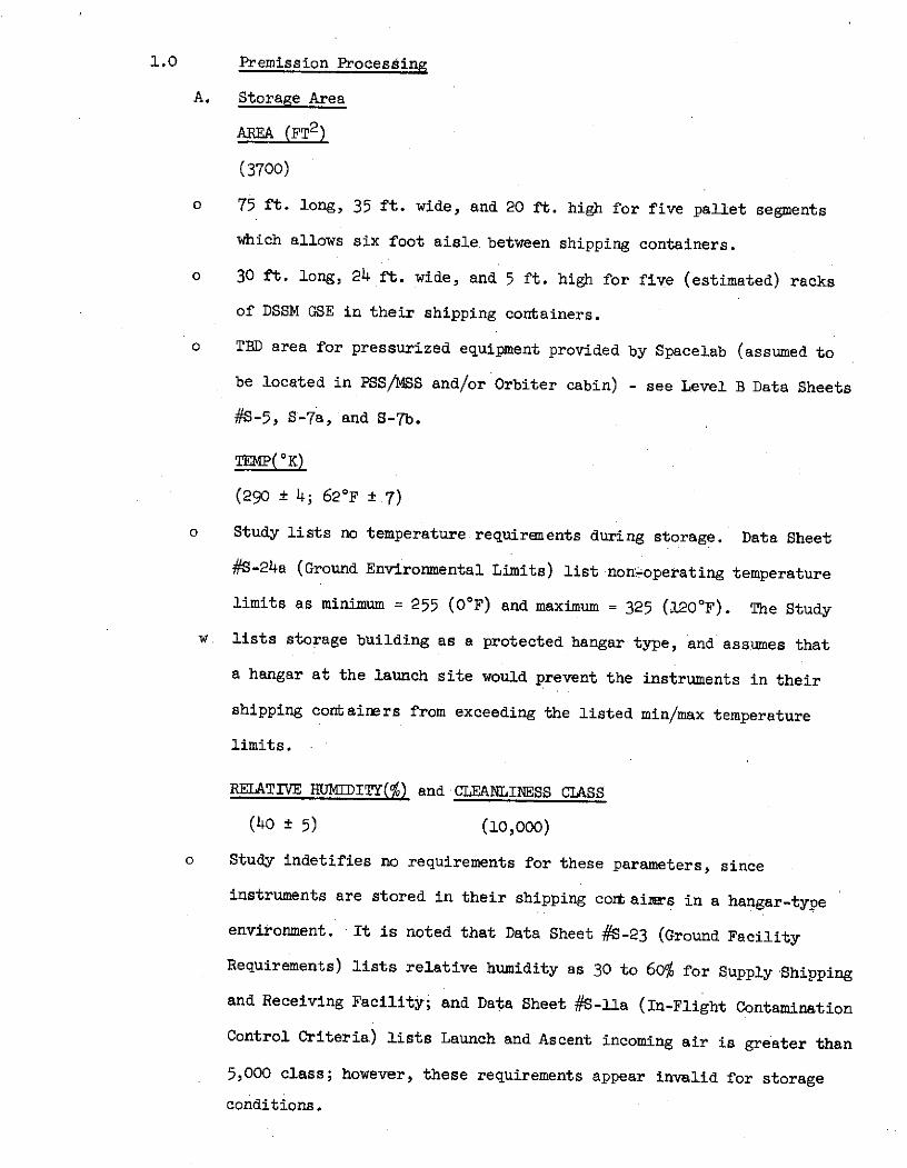
1.0 Premission Processing
A. Storage Area
AREA (FT2)
(3700)
o 75 ft. long, 35 ft. wide, and 20 ft. high for five pallet segments
which allows six foot aisle between shipping containers.
o 30 ft. long, 24 ft. wide, and 5 ft. high for five (estimated) racks
of DSSM GSE in their shipping containers.
o TBD area for pressurized equipment provided by Spacelab (assumed to
be located in PSS/MSS and/or Orbiter cabin) - see Level B Data Sheets
#S-5, S-7a, and S-7b.
TEMP(oK)
(290 ± 4; 620F ± 7)
o Study lists no temperature requirements during storage. Data Sheet
#S-24a (Ground Environmental Limits) list non-@operating temperature
limits as minimum = 255 (O°F) and maximum = 325 (120 °F). The Study
w lists storage building as a protected hangar type, and assumes that
a hangar at the launch site would prevent the instruments in their
shipping containers from exceeding the listed min/max temperature
limits.
RELATIVE HUMIDITY(%) and CLEANLINESS CLASS
(40 ± 5) (10,000)
o Study indetifies no requirements for these parameters, since
instruments are stored in their shipping cort aimrs in a hangar-type
environment. It is noted that Data Sheet #S-23 (Ground Facility
Requirements) lists relative humidity as 30 to 60% for Supply Shipping
and Receiving Facility; and Data Sheet #S-lla (In-Flight Contamination
Control Criteria) lists Launch and Ascent incoming air is greater than
5,000 class; however, these requirements appear invalid for storage
conditions.
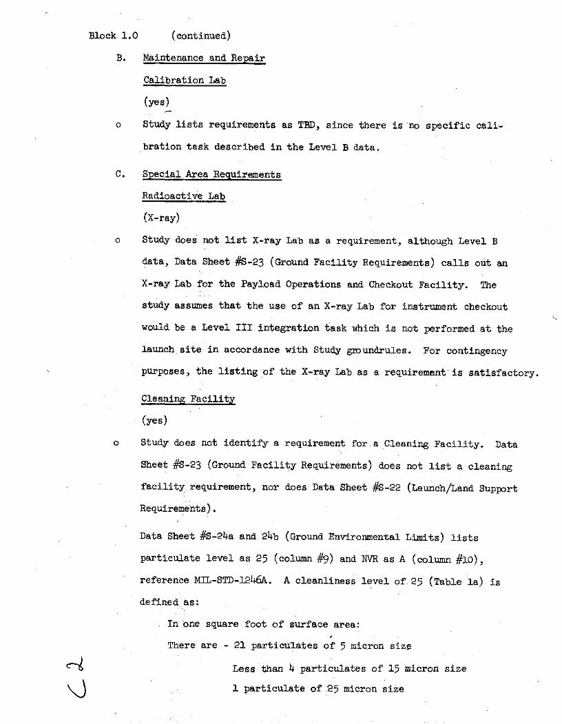
Block 1.0 (continued)
B. Maintenance and Repair
Calibration Lab
(yes)
o Study lists requirements as TBD, since there is no specific cali-
bration task described in the Level B data.
C. Special Area Requirements
Radioactive Lab
(X-ray)
o Study does not list X-ray Lab as a requirement, although Level B
data, Data Sheet #S-23 (Ground Facility Requirements) calls out an
X-ray Lab for the Payload Operations and Checkout Facility. The
study assumes that the use of an X-ray Lab for instrument checkout
would be a Level III integration task which is not performed at the
launch site in accordance with Study groundrules. For contingency
purposes, the listing of the X-ray Lab as a requirement is satisfactory.
Cleaning Facility
(yes)
o Study does not identify a requirement for a Cleaning Facility. Data
Sheet #S-23 (Ground Facility Requirements) does not list a cleaning
facility requirement, nor does Data Sheet #S-22 (Launch/Land Support
Requirements).
Data Sheet #S-24a and 24b (Ground Environmental Limits) lists
particulate level as 25 (column #9) and NVR as A (column #10),
reference MIL-STD-1246A. A cleanliness level of 25 (Table la) is
defined as:
In one square foot of surface area:
There are - 21 particulates of 5 micron size
SLess than 4 particulates of 15 micron size
1 particulate of 25 micron size
Block 1.OC (continued)
Cleaning Facility (continued)
A level A NVR (non volative residue) has less than 1.0 mg of residue
per square foot of surface area. These requirements are extremely
high, there being only one cleanliness level in Table la greater than
25 (10) and no level greater than A in Table lb. The Study concludes
these requirements need investigation prior to listing facilities to
support them.
Other
(Vacuum Chamber - 3 Cu.m.)
(Solar Simulator)
o Study lists no requirements for the above items. Data Sheet #S-23
(Ground Facility Requirements) lists these items as requirements under
Special Handling' (column 8) along with several other itens, like
altitude chamber, integrated test stands, and dark room. Also in
column 9, Notes, other items are listed as requirements, like gamma ray
source, fast neutron source, and alpha particle source.
Basically, the Study feels that it is not necessary to stimulate a
sensor to verify an interface in conducting Level II integration tasks
at the launch site. Therefore, requirements for sensor stimuli were
not listed.
The need for a vacuum chamber to verify Level II integration interfaces
is not identified in ground processing, and the Study does not list
a vacuum chamber as a facility requirement.
D. Office
Number Engineers/Scientists
(2)
o Study estimates 10 required. Interpretation of Data Sheet #S-15
indicates 3 engineers/scientists required to operate the approximate
Block l.OD (continued)
17 instruments during orbital mission on a 24 hour basis. These 17
instruments are mounted on five pallet segments. The Study verifies
individual pallet segment interfaces in parallel, and estimates that
each pallet segment requires 2 engineers/scientists and 4 technicians,
totals therefore are 10 engineers/scientists, and 20 technicians.
Number Technicians
(4)
0 20. See paragraph above for logic.

LAUNCH SITE FACILITY REQUIREMENTS (PHYSICAL)
DEDICATED SOLAR SORTIE MISSION (DSSM)
2.0 Orbiter/Payload Mate and Integrate (Storage Area 3700 ft2 , Temp 290 + 4,
Humid. 40 ± 5% Cleanlines Class 10,000).
o In functional block 2.0 no function for storage is defined; therefore,
the requirement for storage area does not exist.
o Since an anomoly may be discussed at a:.y point in the flow, the require-
ments for Maintenance and Repair and/o:' other Special Area Requirements
should remain valid for this function.
o Office
"GAC estimate for this function would b- 4 :Engineers/Scientists and 12
Technicians based on examination of the Level 'B' description.
o Power Requirements: 2.1 (N/A) 2.2 through 2.5 (28 VDC at 3.0KW, 110 VAC,
400 Hz, 30, 1.5 KW)
Level 'B' data sheet S-23 shows power requirements as follows: 28 VDC at
20-30 KW 115 VAC with no identification of frequency phasing or power
level. Since data sheet S-8 shows no requirement for AC power, it is
assumed that the AC called for on the requirements data sheet is supporting
GSE/STE. No firm requirement may be defined without further definition.
o Special Handling: 2.1
(OH crane, 4 ton capacity)
Level B data lists payload weigbt at 2846 kg. ERNO description bcok
shows 6450 kg for the Spacelab. (2846 + 6450) 2.205 = 20,498 lbs. It
appears that the requirement should be OH crane 11 ton capacity.
There are no other changes recommended.

LAUNCH SITE FACILITY REQUIREMENTS DATA SHEET (PHYICAL)
Block 3.0 Prelaunch and Launch Operations
A. Storage Area
(Area - 3700ft2 )
(Temp - 290 + 4 0K)
(Rel Humid - 40 + 5%)
(Clean Class - 10K)
No storage area facility is required in support )f this activity.
Storage requirements are stated in Activities 1.) and 5.0
Blocks 3.4 & 3.5 Off-line Support
On a contingency basis, the D dicated Solar Sortie Mission should have the
capabilities to perform any maintenlance, repair, servicing, and checkout to
support the launch mission. Although the requirement is on a contingency basis,
the following requirements should 1)e considered as part of the physical
requirements. A specific requirement is servicing LN2 dewars, which are required
for LN2 top-off final servicing.
Power - TBD
Fluids - LN2 , GN2
Data Processing - TBD

LAUNCH SITE FACILITY REQUIREMENTS (PHYSICAL)
Block 4.( Post Landing Operations (Dedicated Solar Sortie Mission)
o Storage Area (3700 ft2)
Since no storage function is defined in this block, no storage area is
required.
There are no lother recommended changes.
LAUNCH SITE FACILIT REQUIREMENTS (PHYSICAL)
DEDICATED SOI AR SORTIE MISSION
Block 5.0 POST MISSION PROCESSIN
For comments refer to Activity 1.0.
Recommended