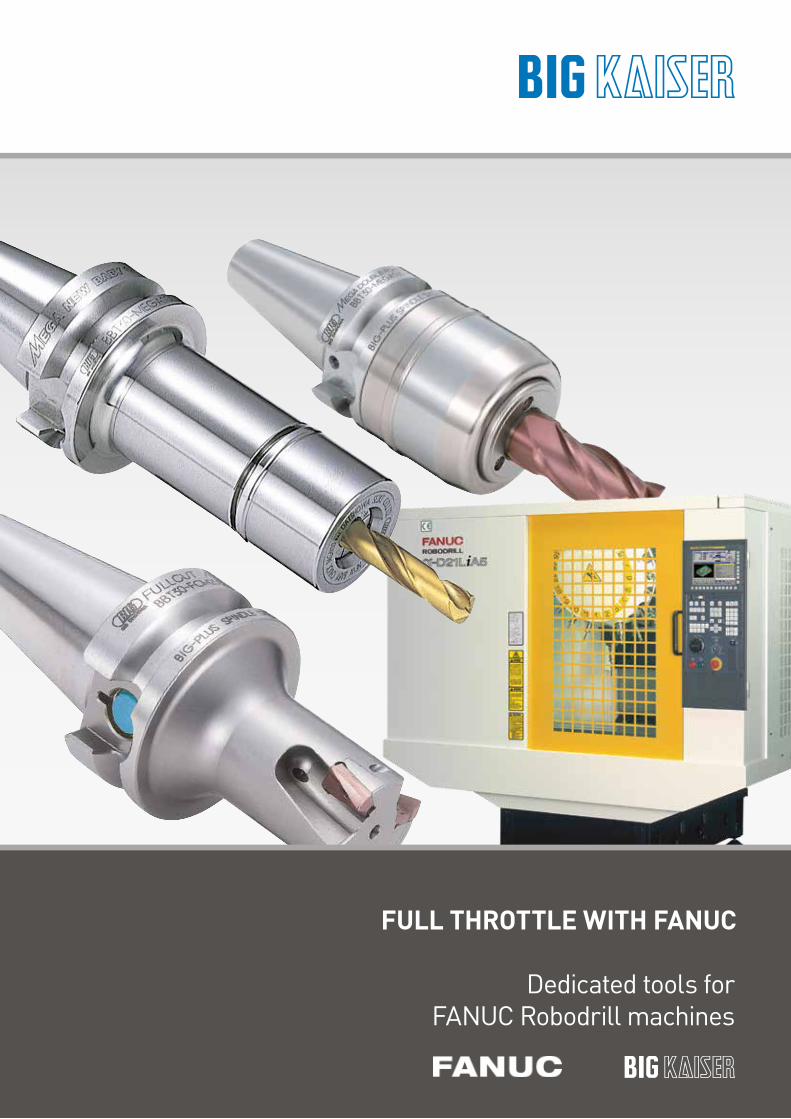
FULL THROTTLE WITH FANUC
Dedicated tools for FANUC Robodrill machines

3
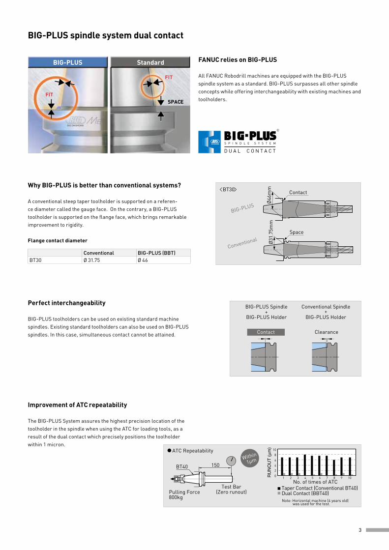
BIG-PLUS spindle system dual contact
FANUC relies on BIG-PLUS
All FANUC Robodrill machines are equipped with the BIG-PLUS spindle system as a standard. BIG-PLUS surpasses all other spindle concepts while offering interchangeability with existing machines and toolholders.
Why BIG-PLUS is better than conventional systems?
A conventional steep taper toolholder is supported on a referen-ce diameter called the gauge face. On the contrary, a BIG-PLUS toolholder is supported on the flange face, which brings remarkable improvement to rigidity.
Improvement of ATC repeatability
The BIG-PLUS System assures the highest precision location of the toolholder in the spindle when using the ATC for loading tools, as a result of the dual contact which precisely positions the toolholder within 1 micron.
Perfect interchangeability
BIG-PLUS toolholders can be used on existing standard machine spindles. Existing standard toolholders can also be used on BIG-PLUS spindles. In this case, simultaneous contact cannot be attained.
Conventional BIG-PLUS (BBT)BT30 Ø 31.75 Ø 46
Flange contact diameter
R
S P I N D L E S Y S T E M
D U A L C O N T A C T
BT30
BIG-PLUS
Contact
Space
Conventional Ø31.
75m
mØ4
6mm
Conventional Spindle+
BIG-PLUS Holder
Clearance
BIG-PLUS Spindle+
BIG-PLUS Holder
Contact
150
Test Bar(Zero runout)
BT40
Pulling Force800kg
Taper Contact (Conventional BT40)Dual Contact (BBT40)
1086420
No. of times of ATC1 2 3 4 5 6 7 8 9 10
ATC Repeatability
Note: Horizontal machine (4 years old) was used for the test.
Within 1µm
FIT
FIT
SPACE
StandardBIG-PLUS
4
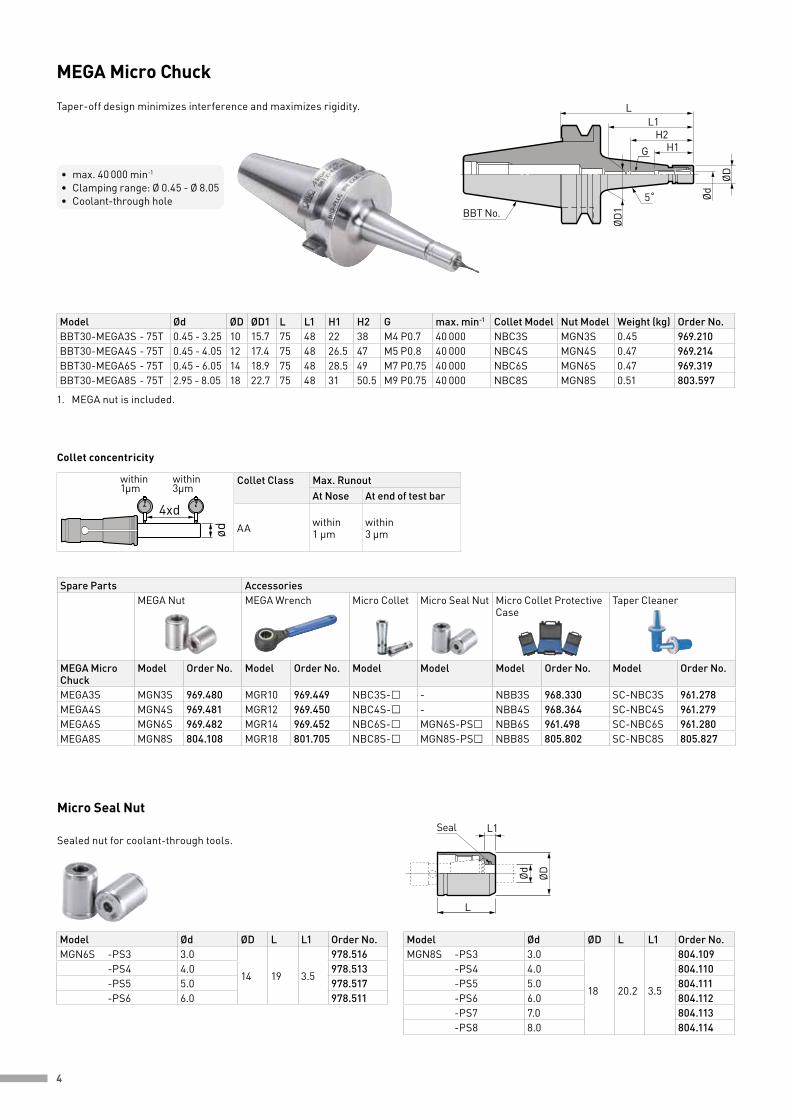
MEGA Micro Chuck
Taper-off design minimizes interference and maximizes rigidity.
Model Ød ØD L L1 Order No.MGN6S -PS3 3.0
14 19 3.5
978.516 -PS4 4.0 978.513 -PS5 5.0 978.517 -PS6 6.0 978.511
Model Ød ØD L L1 Order No.MGN8S -PS3 3.0
18 20.2 3.5
804.109 -PS4 4.0 804.110 -PS5 5.0 804.111 -PS6 6.0 804.112 -PS7 7.0 804.113 -PS8 8.0 804.114
Collet concentricity
Micro Seal Nut
L
L1Seal
ØD
Ød
Collet Class Max. RunoutAt Nose At end of test bar
AA within 1 µm
within 3 µm
within 3µm
within 1µm
4xd
ød
Sealed nut for coolant-through tools.
Spare Parts AccessoriesMEGA Nut MEGA Wrench Micro Collet Micro Seal Nut Micro Collet Protective
CaseTaper Cleaner
MEGA Micro Chuck
Model Order No. Model Order No. Model Model Model Order No. Model Order No.
MEGA3S MGN3S 969.480 MGR10 969.449 NBC3S- - NBB3S 968.330 SC-NBC3S 961.278MEGA4S MGN4S 969.481 MGR12 969.450 NBC4S- - NBB4S 968.364 SC-NBC4S 961.279MEGA6S MGN6S 969.482 MGR14 969.452 NBC6S- MGN6S-PS NBB6S 961.498 SC-NBC6S 961.280MEGA8S MGN8S 804.108 MGR18 801.705 NBC8S- MGN8S-PS NBB8S 805.802 SC-NBC8S 805.827
• max. 40 000 min-1
• Clamping range: Ø 0.45 - Ø 8.05• Coolant-through hole
BBT No.
H2H1
ØD
ØD
1
Ød
L
5˚
L1
G
Model Ød ØD ØD1 L L1 H1 H2 G max. min-1 Collet Model Nut Model Weight (kg) Order No.BBT30-MEGA3S - 75T 0.45 - 3.25 10 15.7 75 48 22 38 M4 P0.7 40 000 NBC3S MGN3S 0.45 969.210BBT30-MEGA4S - 75T 0.45 - 4.05 12 17.4 75 48 26.5 47 M5 P0.8 40 000 NBC4S MGN4S 0.47 969.214BBT30-MEGA6S - 75T 0.45 - 6.05 14 18.9 75 48 28.5 49 M7 P0.75 40 000 NBC6S MGN6S 0.47 969.319BBT30-MEGA8S - 75T 2.95 - 8.05 18 22.7 75 48 31 50.5 M9 P0.75 40 000 NBC8S MGN8S 0.51 803.597
1. MEGA nut is included.

5
MEGA New Baby Chuck
Ideal ultra precision collet holders for high speed machining. Wide range of lengths and a variety of collet series covers all machining applications.
Model Nut Model Collet Model Order No.NBC6 -CE MGN6 NBC6 969.492NBC8 -CE MGN8 NBC8 969.493NBC10 -CE MGN10 NBC10 969.494NBC13 -CE MGN13 NBC13 969.495
Model Nut Model Order No.SC-NBC6 MEGA6N 961.281SC-NBC8 MEGA8N 961.282SC-NBC10 MEGA10N 961.283SC-NBC13 MEGA13N 961.284SC-NBC16 MEGA16N 961.285SC-NBC20 MEGA20N 961.286
Model Ød ØD L L1 H max. min-1 Collet Model Nut Model Weight (kg) Order No.BBT30 - MEGA6N - 60
0.25 - 6 2060 32
23 - 4340 000
NBC 6 MGN 60.47 969.509
- 90 90 62 30 000 0.53 969.510 - MEGA8N - 60
0.5 - 8 2560 34
26 - 4540 000
NBC 8 MGN 80.51 969.511
- 90 90 64 30 000 0.61 969.512 - MEGA10N - 60
1.5 - 10 3060 34
38 - 4840 000
NBC10 MGN100.54 969.513
- 90 90 64 25 000 0.68 969.534 - MEGA13N - 60
2.5 - 13 3560 34
44 - 6340 000
NBC13 MGN130.57 969.516
- 90 90 64 25 000 0.77 969.517 - MEGA16N - 60
2.5 - 16 4260 37 48 - 63 35 000
NBC16 MGN160.61 969.519
- 90 90 67 46 - 68 20 000 0.89 969.520 - MEGA20N - 60
2.5 - 20 4660 - 51 30 000
NBC20 MGN200.64 969.521
- 90 90 - 51 - 68 15 000 0.93 969.522
1. MEGA nut is included.2. “H” indicates the adjustment length with an adjusting screw.3. Adjusting screw cannot be used with BBT30-MEGA20N-60.
Collet Ejector α Taper Cleaner
RubberB L
G
Spare Parts AccessoriesMEGA Nut MEGA Wrench NBC Collet MEGA Perfect
SealAdjusting Screw
MEGA New Baby Chuck
Model Order No. Model Order No. Model Model Model G L B Order No.
MEGA6N MGN6 969.483 MGR20 969.454 NBC6- MPS6- NBA6B M7 12 2 961.527MEGA8N MGN8 969.484 MGR25 969.456 NBC8- MPS8- NBA8B M9 13 2.5 961.550MEGA10N MGN10 969.485 MGR30 969.458 NBC10- MPS10- NBA10B M11 16 3 961.572MEGA13N MGN13 969.486 MGR35 969.460 NBC13- MPS13- NBA13B M14 20 4 961.598MEGA16N MGN16 969.487 MGR42 969.462 NBC16- MPS16- NBA16B M18 20 4 961.632MEGA20N MGN20 969.488 MGR46 969.465 NBC20- MPS20- NBA20B M21 20 4 961.680
• max. 40 000 min-1
• Clamping range: Ø 0.25 - Ø 20• Coolant-through hole
H
ØD
Ød
L1L
BBT No. Adjusting Screw (Optional)
6
Model Ød ØD ØD1 L L1 L2 H E Max. min-1 Weight (kg) Order No.BBT30 -MEGA16DS - 60 16 46 47 62.5 28
-64
5230 000 0.76 978.030
-MEGA20DS - 65 20 50 51 67.5 33 62 25 000 0.82 978.184
H
Adjusting Screw(Optional) Coolant
BBT No.
ØDØd
LL1
ØD1
Min. Clamping Length E
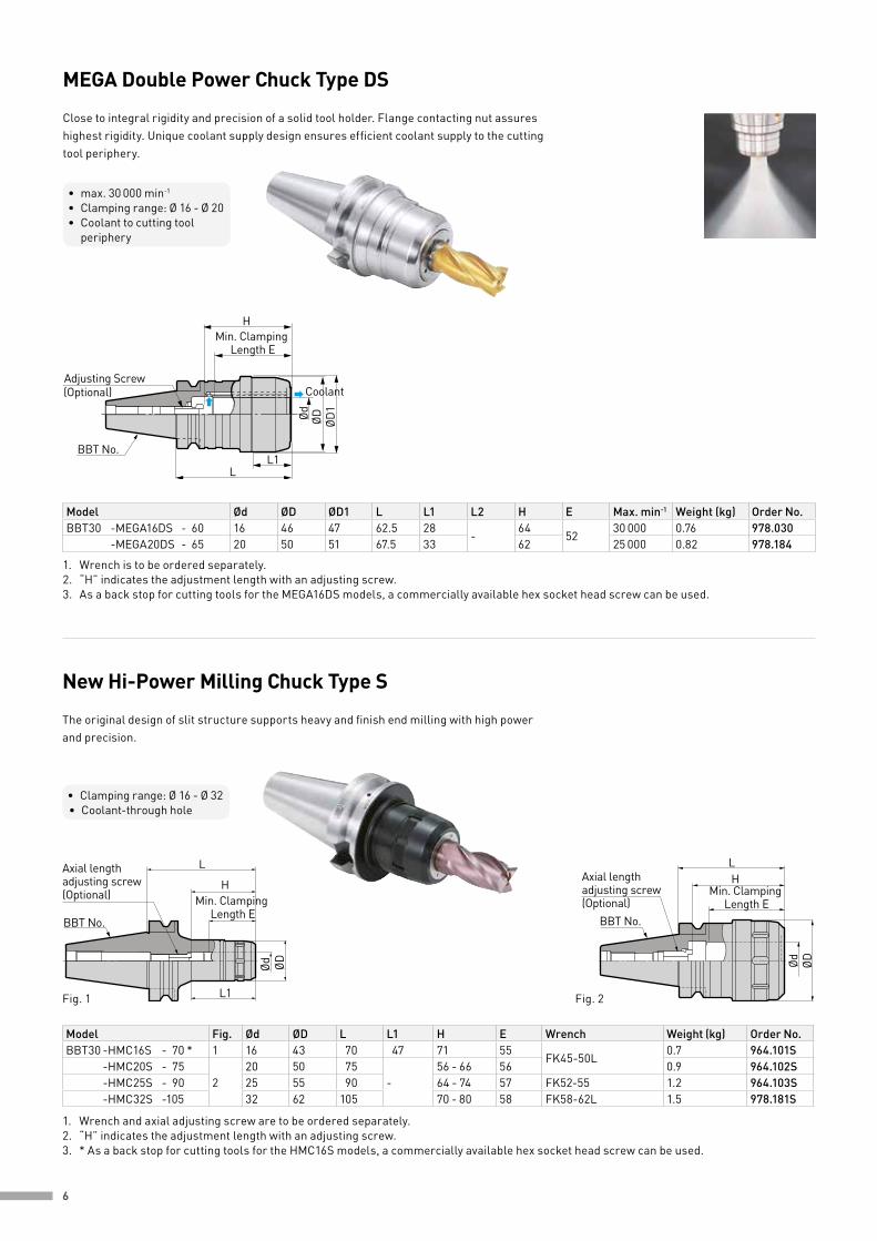
MEGA Double Power Chuck Type DS
Close to integral rigidity and precision of a solid tool holder. Flange contacting nut assures highest rigidity. Unique coolant supply design ensures efficient coolant supply to the cutting tool periphery.
• max. 30 000 min-1
• Clamping range: Ø 16 - Ø 20• Coolant to cutting tool periphery
1. Wrench is to be ordered separately. 2. “H” indicates the adjustment length with an adjusting screw.3. As a back stop for cutting tools for the MEGA16DS models, a commercially available hex socket head screw can be used.
Ød ØD
HMin. Clamping
Length E
L
L1
Axial length adjusting screw(Optional)
BBT No.
Axial length adjusting screw (Optional)
ØDØd
HL
BBT No.
Min. Clamping Length E
New Hi-Power Milling Chuck Type S
The original design of slit structure supports heavy and finish end milling with high power and precision.
• Clamping range: Ø 16 - Ø 32• Coolant-through hole
Fig. 1 Fig. 2
Model Fig. Ød ØD L L1 H E Wrench Weight (kg) Order No.BBT30 -HMC16S - 70 * 1 16 43 70 47 71 55
FK45-50L0.7 964.101S
-HMC20S - 752
20 50 75-
56 - 66 56 0.9 964.102S -HMC25S - 90 25 55 90 64 - 74 57 FK52-55 1.2 964.103S -HMC32S -105 32 62 105 70 - 80 58 FK58-62L 1.5 978.181S
1. Wrench and axial adjusting screw are to be ordered separately. 2. “H” indicates the adjustment length with an adjusting screw.3. * As a back stop for cutting tools for the HMC16S models, a commercially available hex socket head screw can be used.
7
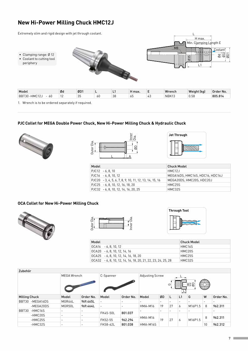
OCA Collet for New Hi-Power Milling Chuck
PJC Collet for MEGA Double Power Chuck, New Hi-Power Milling Chuck & Hydraulic Chuck
Model Chuck ModelOCA16 - 6, 8, 10, 12 HMC16SOCA20 - 6, 8, 10, 12, 14, 16 HMC20SOCA25 - 6, 8, 10, 12, 14, 16, 18, 20 HMC25SOCA32 - 6, 8, 10, 12, 14, 16, 18, 20, 21, 22, 23, 24, 25, 28 HMC32S
Model Chuck Model PJC12 - 6, 8, 10 HMC12JPJC16 - 6, 8, 10, 12 MEGA16DS, HMC16S, HDC16, HDC16JPJC20 - 3, 4, 5, 6, 7, 8, 9, 10, 11, 12, 13, 14, 15, 16 MEGA20DS, HMC20S, HDC20JPJC25 - 6, 8, 10, 12, 16, 18, 20 HMC25SPJC32 - 6, 8, 10, 12, 14, 16, 20, 25 HMC32S
L
L1
ØDWG
ZubehörMEGA Wrench C-Spanner Adjusting Screw
Milling Chuck Model Order No. Model Order No. Model ØD L L1 G W Order No.BBT30 -MEGA16DS MGR46L 969.465L - - - - - - - - - -MEGA20DS MGR50L 969.464L - - HMA-M16 19 27 6 M16P1.5 8 962.311BBT30 -HMC16S - -
FK45-50L 801.037- - - - - -
-HMC20S - -HMA-M16
19 27 6 M16P1.58 962.311
-HMC25S - - FK52-55 962.294 -HMC32S - - FK58-62L 801.038 HMA-M16S 10 962.312
ØD
AL
Inne
r D
ia.
Oute
r Dia
.
Jet Through
Oute
r Dia
.
Inne
r Dia
.
Through Tool
L1
L
M8
H max.
Ø35 ØD
1
Ød Ø32
Min. Clamping Length E
Coolant
New Hi-Power Milling Chuck HMC12J
Extremely slim and rigid design with jet through coolant.
Model Ød ØD1 L L1 H max. E Wrench Weight (kg) Order No.BBT30 -HMC12J - 60 12 35 60 38 65 43 NBK13 0.58 805.814
1. Wrench is to be ordered separately if required.
• Clamping range: Ø 12• Coolant to cutting tool periphery

8
Easy clamping with 1 wrench
The cutting tool can be clamped or unclamped easily and securely with just 1 wrench.
L
Ød ØD ØD1
L1
Adjustable CutterLength H
Min. Clamping Length EAdjusting ScrewLeft-hand thread(Optional)
Ød ØD ØD1
L
ØD2
L2L1
Adjustable CutterLength HAdjusting Screw
Left-hand thread(Optional)
Min. Clamping Length E
Adjustable CutterLength H
ØD ØD1
L32
ØD2
L2L1
Adjusting ScrewLeft-hand thread(Optional)
Ød
Min. Clamping Length E
Hydraulic Chuck Standard
For high precision machining in Automotive, Aerospace, Medical and Die & Mold.
• Clamping range: Ø 6 - Ø 25• Coolant-through hole
Model Fig. Ød ØD ØD1 ØD2 L L1 L2 H E Adjusting Screw (optional)
Weight (kg) Order No.
BBT30 -HDC6 - 451
630
46
-45 7
-35 - 50
28
HDA6-05020 0.61 978.071 - 75
2675 40
28 - 50 HDA6-050320.67 978.034
-105 2 31 105 43 72 0.82 978.073 -HDC8 - 45
18
32-
45 7-
35 - 50 HDA8-06020 0.61 978.075 - 75
2875 41
28 - 50 HDA8-060320.69 978.076
-105 2 33 105 44 72 0.84 978.078 -HDC10 - 45
110
34-
45 7-
45 - 5533
HDA10-08015 0.60 978.080 - 75
3075 36
33 - 55 HDA10-080320.74 978.081
-105 2 36 105 45 66 0.91 978.083 -HDC12 - 45
112
36-
45 7-
55 - 6038
HDA12-10010 0.58 978.085 - 75
3275 36
38 - 60 HDA12-100320.75 978.086
-105 2 38 105 45 67 0.94 978.088 -HDC16 - 45 **
116
42
-
45 7-
70
43
- 0.55 978.092 - 75
3875 35
43 - 70HDA16-12030 0.77 978.025
-105 2 105 47 HDA16-12037 1.06 805.550 -HDC20 - 60 *
320 38
5360 - 14 43 - 54
HDA16-120300.77 978.095
- 75 46 75 16 26 46 - 70 0.85 978.038 -105 2 46
-105 40
-43 - 70
HDA16-120371.02 805.551
-HDC25 -105 3 25 55 63 105 44 52 - 80 1.6 978.097
1. Straight collet (reduction sleeve) is available. 2. * Straight collet can not be used with BBT30-HDC20-60.3. ** Adjusting screw can not be used with BBT30-HDC16-45.
Fig. 1
Fig. 3Fig. 2
9
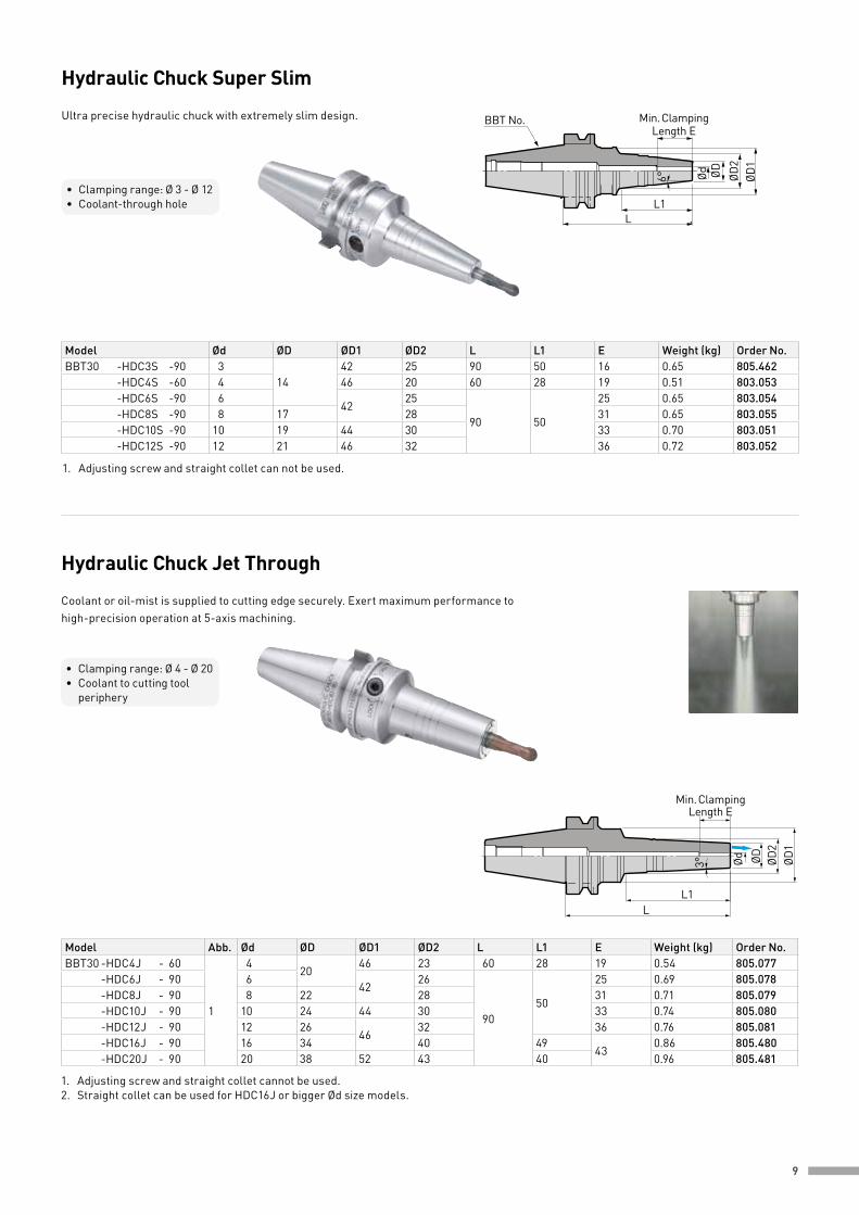
Model Ød ØD ØD1 ØD2 L L1 E Weight (kg) Order No.BBT30 -HDC3S -90 3
1442 25 90 50 16 0.65 805.462
-HDC4S -60 4 46 20 60 28 19 0.51 803.053 -HDC6S -90 6
4225
90 50
25 0.65 803.054 -HDC8S -90 8 17 28 31 0.65 803.055 -HDC10S -90 10 19 44 30 33 0.70 803.051 -HDC12S -90 12 21 46 32 36 0.72 803.052
Model Abb. Ød ØD ØD1 ØD2 L L1 E Weight (kg) Order No.BBT30 -HDC4J - 60
1
420
46 23 60 28 19 0.54 805.077 -HDC6J - 90 6
4226
9050
25 0.69 805.078 -HDC8J - 90 8 22 28 31 0.71 805.079 -HDC10J - 90 10 24 44 30 33 0.74 805.080 -HDC12J - 90 12 26
4632 36 0.76 805.081
-HDC16J - 90 16 34 40 4943
0.86 805.480 -HDC20J - 90 20 38 52 43 40 0.96 805.481
L1L
ØD2
Ød ØD ØD1
Min. ClampingLength E
6°
BBT No.
Hydraulic Chuck Super Slim
Ultra precise hydraulic chuck with extremely slim design.
• Clamping range: Ø 3 - Ø 12• Coolant-through hole
LL1
Ød ØD ØD1
ØD2
Min. ClampingLength E
3°
Hydraulic Chuck Jet Through
Coolant or oil-mist is supplied to cutting edge securely. Exert maximum performance to high-precision operation at 5-axis machining.
• Clamping range: Ø 4 - Ø 20• Coolant to cutting tool periphery
1. Adjusting screw and straight collet can not be used.
1. Adjusting screw and straight collet cannot be used.2. Straight collet can be used for HDC16J or bigger Ød size models.
10
Ø12
Micro ColletNBC4S-
L2
ØD
LL1
12
BBT No.
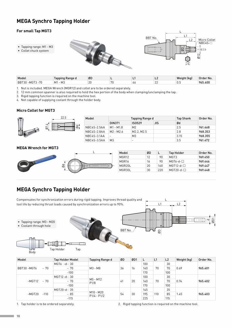
1. Nut is included. MEGA Wrench (MGR12) and collet are to be ordered separately.2. 12 mm common spanner is also required to hold the hex portion of the body when clamping/unclamping the tap.3. Rigid tapping function is required on the machine tool.4. Not capable of supplying coolant through the holder body.
Model Tapping Range d ØD L L1 L2 Weight (kg) Order No.BBT30 -MGT3 -70 M1 - M3 20 70 46 22 0.5 965.400
• Tapping range: M1 - M3• Collet chuck system
MEGA Synchro Tapping Holder
For small Tap MGT3
Ø7.4
Ød
22.5 Model Tapping Range d Tap Shank Order No.DIN371 ISO529 JIS Ød
NBC4S -2.5AA M1 - M1.8 M2 2.5 961.468NBC4S -2.8AA M2 - M2.6 M2.2, M2.5 2.8 968.353NBC4S -3.1AA - M3 3.15 968.355NBC4S -3.5AA M3 - 3.5 961.472
Micro Collet for MGT3
Ød LO
CK
LMEGA Wrench for MGT3
Model ØD L Tap Holder Order No.MGR12 12 90 MGT3 969.450MGR16 16 90 MGT6-d- 969.446MGR20L 20 160 MGT12-d- 969.447MGR30L 30 220 MGT20-d- 969.448
BodyTap Holder Tap
L2L
dØD
1
ØD
L1
BBT No.
MEGA Synchro Tapping Holder
Compensates for synchronization errors during rigid tapping. Improves thread quality and tool life by reducing thrust loads caused by synchronization errors up to 90%.
• Tapping range: M3 - M20• Coolant-through hole
Model Tap Holder Model Tapping Range d ØD ØD1 L L1 L2 Weight (kg) Order No.
BBT30 -MGT6 - 70MGT6 -d - 30
M3 - M8 36 16100
7030
0.69 965.401 - 70 140 70 -100 170 100
-MGT12 - 70MGT12 -d - 30
M5 - M12 P1/8 41 20
10070
300.74 965.402 - 70 140 70
-100 170 100
-MGT20 -110MGT20 -d - 35
M10 - M20 P1/4 - P1/2 54 30
145110
351.45 965.403 - 85 195 85
-115 225 115
1. Tap holder is to be ordered separately. 2. Rigid tapping function is required on the machine tool.
11
L
d2
dØD
H
Ød1
Synchro Adjuster
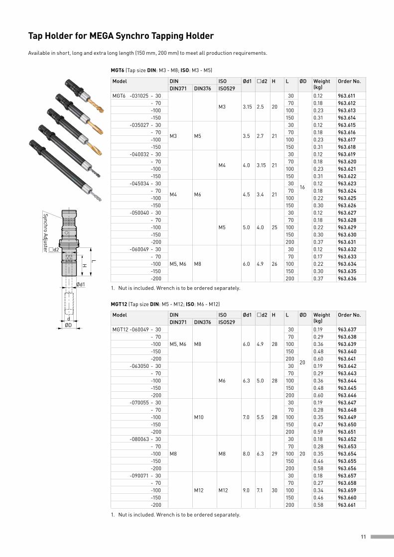
MGT6 (Tap size DIN: M3 - M8; ISO: M3 - M5)
1. Nut is included. Wrench is to be ordered separately.
1. Nut is included. Wrench is to be ordered separately.
MGT12 (Tap size DIN: M5 - M12; ISO: M6 - M12)
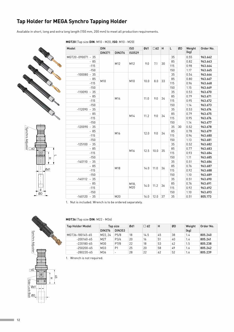
Tap Holder for MEGA Synchro Tapping Holder
Available in short, long and extra long length (150 mm, 200 mm) to meet all production requirements.
Model DIN ISO Ød1 d2 H L ØD Weight (kg)
Order No.DIN371 DIN376 ISO529
MGT6 -031025 - 30
M3 3.15 2.5 20
30
16
0.12 963.611 - 70 70 0.18 963.612 -100 100 0.23 963.613 -150 150 0.31 963.614 -035027 - 30
M3 M5 3.5 2.7 21
30 0.12 963.615 - 70 70 0.18 963.616 -100 100 0.23 963.617 -150 150 0.31 963.618 -040032 - 30
M4 4.0 3.15 21
30 0.12 963.619 - 70 70 0.18 963.620 -100 100 0.23 963.621 -150 150 0.31 963.622 -045034 - 30
M4 M6 4.5 3.4 21
30 0.12 963.623 - 70 70 0.18 963.624 -100 100 0.22 963.625 -150 150 0.30 963.626 -050040 - 30
M5 5.0 4.0 25
30 0.12 963.627 - 70 70 0.18 963.628 -100 100 0.22 963.629 -150 150 0.30 963.630 -200 200 0.37 963.631 -060049 - 30
M5, M6 M8 6.0 4.9 26
30 0.12 963.632 - 70 70 0.17 963.633 -100 100 0.22 963.634 -150 150 0.30 963.635 -200 200 0.37 963.636
Model DIN ISO Ød1 d2 H L ØD Weight (kg)
Order No.DIN371 DIN376 ISO529
MGT12 -060049 - 30
M5, M6 M8 6.0 4.9 28
30
20
0.19 963.637 - 70 70 0.29 963.638 -100 100 0.36 963.639 -150 150 0.48 963.640 -200 200 0.60 963.641 -063050 - 30
M6 6.3 5.0 28
30 0.19 963.642 - 70 70 0.29 963.643 -100 100 0.36 963.644 -150 150 0.48 963.645 -200 200 0.60 963.646 -070055 - 30
M10 7.0 5.5 28
30
20
0.19 963.647 - 70 70 0.28 963.648 -100 100 0.35 963.649 -150 150 0.47 963.650 -200 200 0.59 963.651 -080063 - 30
M8 M8 8.0 6.3 29
30 0.18 963.652 - 70 70 0.28 963.653 -100 100 0.35 963.654 -150 150 0.46 963.655 -200 200 0.58 963.656 -090071 - 30
M12 M12 9.0 7.1 30
30 0.18 963.657 - 70 70 0.27 963.658 -100 100 0.34 963.659 -150 150 0.46 963.660 -200 200 0.58 963.661
12
L
d2
dØD
H
Ød1
Synchro Adjuster
MGT20 (Tap size DIN: M10 - M20; ISO: M10 - M20)
Model DIN ISO Ød1 d2 H L ØD Weight (kg)
Order No.DIN371 DIN376 ISO529
MGT20 -090071 - 35
M12 M12 9.0 7.1 30
35
30
0.55 963.662 - 85 85 0.82 963.663 -115 115 0.98 963.664 -150 150 1.17 963.665 -100080 - 35
M10 M10 10.0 8.0 33
35 0.54 963.666 - 85 85 0.80 963.667 -115 115 0.96 963.668 -150 150 1.15 963.669 -110090 - 35
M14 11.0 9.0 34
35 0.53 963.670 - 85 85 0.79 963.671 -115 115 0.95 963.672 -150 150 1.14 963.673 -112090 - 35
M14 11.2 9.0 34
35 0.53 963.674 - 85 85 0.79 963.675 -115 115 0.95 963.676 -150 150 1.14 963.677 -120090 - 35
M16 12.0 9.0 34
35 0.52 963.678 - 85 85 0.78 963.679 -115 115 0.94 963.680 -150 150 1.13 963.681 -125100 - 35
M16 12.5 10.0 35
35 0.52 963.682 - 85 85 0.77 963.683 -115 115 0.93 963.684 -150 150 1.11 963.685 -140110 - 35
M18 14.0 11.0 36
35 0.51 963.686 - 85 85 0.76 963.687 -115 115 0.92 963.688 -150 150 1.10 963.689 -140112 - 35
M18, M20 14.0 11.2 36
35 0.51 963.690 - 85 85 0.76 963.691 -115 115 0.92 963.692 -150 150 1.10 963.693 -160120 - 35 M20 16.0 12.0 37 35 0.51 805.173
1. Nut is included. Wrench is to be ordered separately.
Tap Holder for MEGA Synchro Tapping Holder
Available in short, long and extra long length (150 mm, 200 mm) to meet all production requirements.
65
d2
Ød1
ØD
H
Synchro AdjusterSide Lock B
olt
1. Wrench is not required.
Tap Holder Model Tap size Ød1 d2 H ØD Weight Order No.DIN376 DIN353 (kg)
MGT36-180145-65 M22, 24 P5/8 18 14.5 45 38 1.4 805.240 -200160-65 M27 P3/4 20 16 51 40 1.4 805.241 -220180-65 M30 P7/8 22 18 53 42 1.5 805.238 -250200-65 M33 P1 25 20 58 49 1.6 805.242 -280220-65 M36 - 28 22 62 52 1.6 805.239
MGT36 (Tap size DIN: M22 - M36)
13
A2 A1
L
2-G
ØDØd
L1H
BBT No.
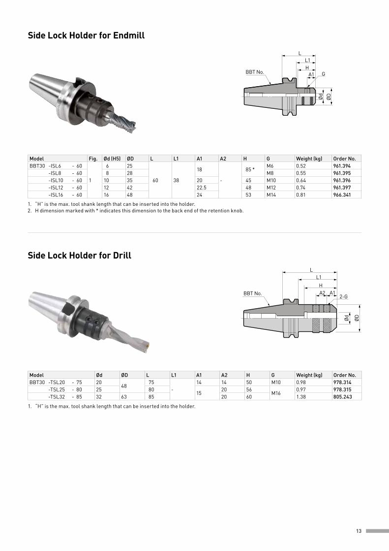
1. “H” is the max. tool shank length that can be inserted into the holder.
Side Lock Holder for Drill
Model Ød ØD L L1 A1 A2 H G Weight (kg) Order No.BBT30 -TSL20 - 75 20
4875
-14 14 50 M10 0.98 978.314
-TSL25 - 80 25 8015
20 56M16
0.97 978.315 -TSL32 - 85 32 63 85 20 60 1.38 805.243
LL1H
ØDØd
GA1BBT No.
Side Lock Holder for Endmill
Model Fig. Ød (H5) ØD L L1 A1 A2 H G Weight (kg) Order No.BBT30 -ISL6 - 60
1
6 25
60 38
18
-
85 *M6 0.52 961.394
-ISL8 - 60 8 28 M8 0.55 961.395 -ISL10 - 60 10 35 20 45 M10 0.64 961.396 -ISL12 - 60 12 42 22.5 48 M12 0.74 961.397 -ISL16 - 60 16 48 24 53 M14 0.81 966.341
1. “H” is the max. tool shank length that can be inserted into the holder.2. H dimension marked with * indicates this dimension to the back end of the retention knob.

14
Model Fig. ØD (H6) ØD1 L L1 Driver Keys G ØC min. Weight (kg) Order No.L2 W
BBT30 -FMH16 - 37 - 35 1 16 37 35 16 5 8 M8 28 0.53 978.326 -FMH22 - 47 - 45
222
47 45 18 5 10 M10 38 0.73 978.259 -FMH22 - 60 - 45 60 45 18 5 10 M10 38 0.90 805.569 -FMH27 - 60 - 45 27 60 45 20 6 12 M12 38 0.89 978.273
Air-bleeding hole
BBT No. L1L
ØD1
ØDØd
3˚
Min. Clamping Length E
L1L
BBT No.
Air-bleeding hole
ØD1
ØDØd
3˚
Max. Insertion Length H
Min. Clamping Length E
1. Use carbide cutter within a tolerance of h6.2. * Use carbide cutter within a tolerance of h5.
Shrink Chuck Standard
Substantial body provides higher rigidity. Available from 4mm clamping diameter.
• Clamping range: Ø 4 - Ø 20• Coolant-through hole
Fig. 1 Fig. 2
Model Fig. Ød ØD ØD1 L L1 E H Weight (kg) Order No.BBT30 -SRC4 - 75 *
14 10 14.6
75
44 16-
0.45 978.001 -SRC6 - 75 6 14 19.0
4726
0.47 978.002 -SRC8 - 75 8 18 23.0 0.51 978.003 -SRC10 - 75
210 22 27.0 32 62 0.56 978.004
-SRC12 - 75 12 24 29.0 36 72 0.58 978.005 -SRC16 - 75 16 28 33.0 48 38 80 0.62 978.006
G
W
ØD1
ØCØD
L2L1L
ØD ØD1
ØC
W
G
L L1L2BBT30 : 30(Min)
BBT40 : 45(Min)
Face Mill Arbor Type FMH
For cutters that require a coolant hole through the pilot.
Fig. 2
Fig. 1
1. By utilizing a clamping bolt with a hole through, coolant is supplied through the bolt.2. Hexagon socket head cap screw is included.
15
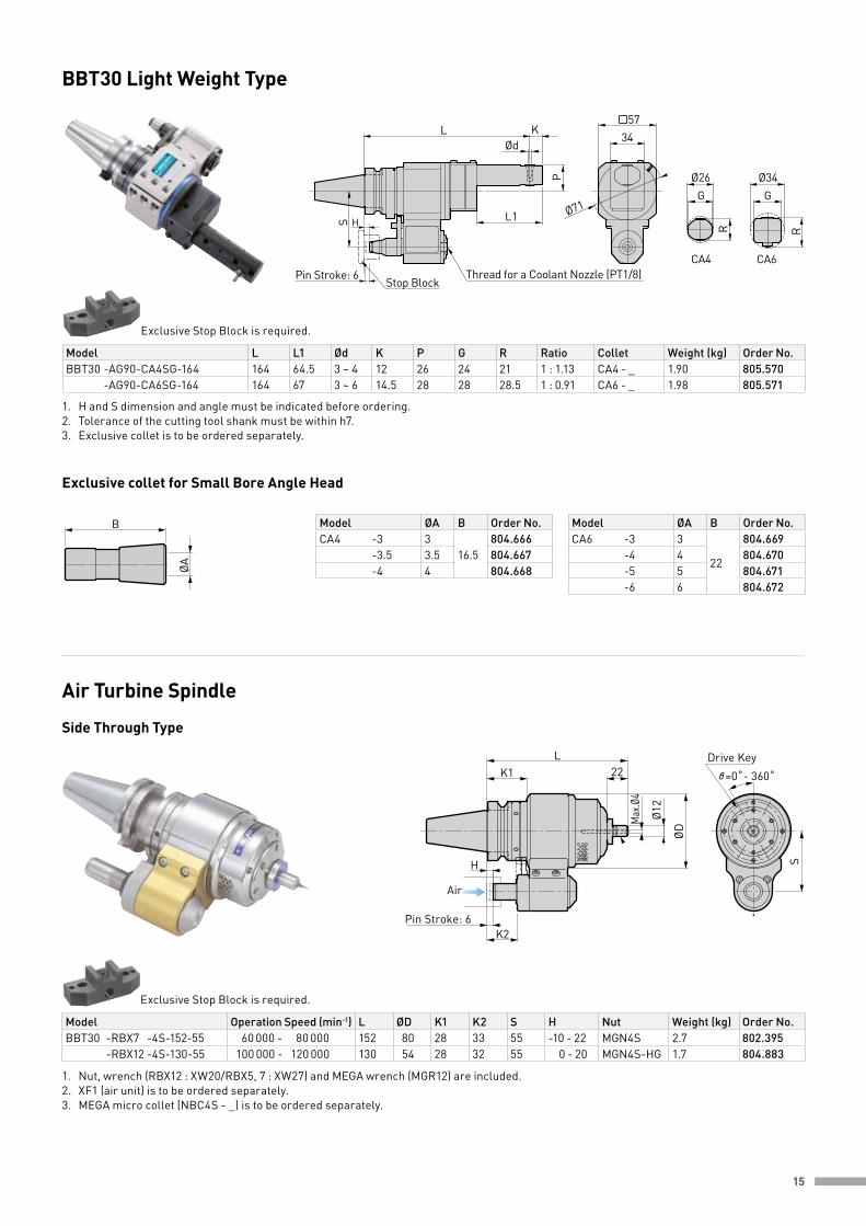
Air Turbine Spindle
Side Through Type
Exclusive Stop Block is required.
1. Nut, wrench (RBX12 : XW20/RBX5, 7 : XW27) and MEGA wrench (MGR12) are included.2. XF1 (air unit) is to be ordered separately. 3. MEGA micro collet (NBC4S - _) is to be ordered separately.
Model Operation Speed (min-1) L ØD K1 K2 S H Nut Weight (kg) Order No.BBT30 -RBX7 -4S-152-55 60 000 - 80 000 152 80 28 33 55 -10 - 22 MGN4S 2.7 802.395 -RBX12 -4S-130-55 100 000 - 120 000 130 54 28 32 55 0 - 20 MGN4S-HG 1.7 804.883
G
R
G
R
34
P
K
L
Stop BlockThread for a Coolant Nozzle (PT1/8)
CA4 CA6
57
1S
LØd
Ø26 Ø34
Ø71
Pin Stroke: 6
H
BBT30 Light Weight Type
1. H and S dimension and angle must be indicated before ordering.2. Tolerance of the cutting tool shank must be within h7.3. Exclusive collet is to be ordered separately.
Exclusive Stop Block is required.
Model L L1 Ød K P G R Ratio Collet Weight (kg) Order No.BBT30 -AG90-CA4SG-164 164 64.5 3 ~ 4 12 26 24 21 1 : 1.13 CA4 - _ 1.90 805.570 -AG90-CA6SG-164 164 67 3 ~ 6 14.5 28 28 28.5 1 : 0.91 CA6 - _ 1.98 805.571
ØA
B
Exclusive collet for Small Bore Angle Head
Model ØA B Order No.CA6 -3 3
22
804.669 -4 4 804.670 -5 5 804.671 -6 6 804.672
Model ØA B Order No.CA4 -3 3
16.5804.666
-3.5 3.5 804.667 -4 4 804.668
S
Drive Key
=0˚- 360˚
Air
Pin Stroke: 6K2
H
L
Max
.Ø4
ØD
Ø12
K1 22

16
Fig. 1
Fig. 1
Fig. 2 (Long Type)
Fig. 2 (Long Type)
Fullcut Mill FCR
Fullcut Mill FCM
For Ramping and Helical millingClamping Range: Ø 16 - Ø 32
Integral Type, for Square Sholder and Slot millingClamping Range: Ø 16 - Ø 32
LL1
L
HL1
ØD1
ØDØd
ØDØd
LL1
GH
L
LL2
L1
LL2
L1ap
ap
HA2 A1 2-G
A1
ØDØd
ØD
ØD ØD
Ød
5˚3
Einstellschraube (optional)
H2H1G
LL1
L
HL1
ØD1
ØDØd
ØDØd
LL1
GH
L
LL2
L1
LL2
L1ap
ap
HA2 A1 2-G
A1
ØDØd
ØD
ØD ØD
Ød
5˚3
Einstellschraube (optional)
H2H1G
Cutter Dia. ØD Model Fig. ap L L1 L2 No. of Inserts Insert Size Weight (kg) Order No.16 BBT30 -FCR16082 -65
18
6528
43
2 BRG16 0.5 966.68320 -FCR20083 -65
3BRG20 0.5 966.685
25 -FCR25083 -65 33 BRG25 0.6 966.68732 -FCR32103 -65 10 40 BRG32 0.6 966.68916 BBT30 -FCR16082L -85
28
85
45
63 2
BRG16 0.5 966.68420 -FCR20082L -85
50BRG20 0.5 966.686
25 -FCR25082L -85 BRG25 0.6 966.68832 -FCR32102L -85 10 60 BRG32 0.7 966.690
Cutter Dia. ØD Model Fig. ap L L1 L2 No. of Inserts Insert Size Weight (kg) Order No.16 BBT30 -FCM16092 -65
19
65
23 43 2 ARG16 0.5 966.21620 -FCM20093 -65 28 43
3ARG20 0.5 966.217
25 -FCM25093 -65 33 43 ARG25 0.5 966.21832 -FCM32113 -65 11 38 43 ARG32 0.6 966.21916 BBT30 -FCM16092L -85
29
85
45 63
2
ARG16 0.5 966.08120 -FCM20092L -85 50 63 ARG20 0.5 966.08225 -FCM25092L -85 50 63 ARG25 0.6 966.08332 -FCM32112L -85 11 60 63 ARG32 0.7 966.084
Full Cut Mill FCMTool BBT30-FCM20092L-85
TimeInsert ARG200904ACZ350S (dry)
Cutting data Diameter 20 Ø - mm
3' 36''
Number of teeth 2 toothCutting speed 150 m/minFeed / tooth 0.12 mm/toothRevolution 2 387 min-1
Feed 573 mm/minAd 9 mmAe 20 mm
1. Wrench is included. Inserts are to be ordered separately.
1. Wrench is included. Inserts are to be ordered separately.
17
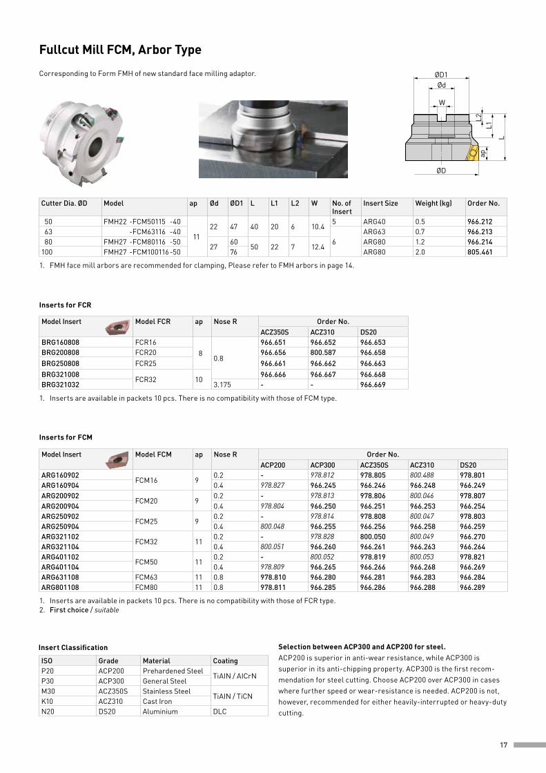
ISO Grade Material CoatingP20 ACP200 Prehardened Steel
TiAIN / AICrNP30 ACP300 General SteelM30 ACZ350S Stainless Steel
TiAIN / TiCNK10 ACZ310 Cast IronN20 DS20 Aluminium DLC
Model Insert Model FCR ap Nose R Order No.ACZ350S ACZ310 DS20
BRG160808 FCR16 8
0.8
966.651 966.652 966.653BRG200808 FCR20 966.656 800.587 966.658BRG250808 FCR25 966.661 966.662 966.663BRG321008
FCR32 10966.666 966.667 966.668
BRG321032 3.175 - - 966.669
Model Insert Model FCM ap Nose R Order No.ACP200 ACP300 ACZ350S ACZ310 DS20
ARG160902FCM16 9
0.2 - 978.812 978.805 800.488 978.801ARG160904 0.4 978.827 966.245 966.246 966.248 966.249ARG200902
FCM20 90.2 - 978.813 978.806 800.046 978.807
ARG200904 0.4 978.804 966.250 966.251 966.253 966.254ARG250902
FCM25 90.2 - 978.814 978.808 800.047 978.803
ARG250904 0.4 800.048 966.255 966.256 966.258 966.259ARG321102
FCM32 110.2 - 978.828 800.050 800.049 966.270
ARG321104 0.4 800.051 966.260 966.261 966.263 966.264ARG401102
FCM50 110.2 - 800.052 978.819 800.053 978.821
ARG401104 0.4 978.809 966.265 966.266 966.268 966.269ARG631108 FCM63 11 0.8 978.810 966.280 966.281 966.283 966.284ARG801108 FCM80 11 0.8 978.811 966.285 966.286 966.288 966.289
Inserts for FCR
Inserts for FCM
1. Inserts are available in packets 10 pcs. There is no compatibility with those of FCM type.
1. FMH face mill arbors are recommended for clamping, Please refer to FMH arbors in page 14.
1. Inserts are available in packets 10 pcs. There is no compatibility with those of FCR type. 2. First choice / suitable
Insert Classification Selection between ACP300 and ACP200 for steel.ACP200 is superior in anti-wear resistance, while ACP300 is superior in its anti-chipping property. ACP300 is the first recom-mendation for steel cutting. Choose ACP200 over ACP300 in cases where further speed or wear-resistance is needed. ACP200 is not, however, recommended for either heavily-interrupted or heavy-duty cutting.
ØD1Ød
W
ØD
L
L2L1
ap
Fullcut Mill FCM, Arbor Type Corresponding to Form FMH of new standard face milling adaptor.
Cutter Dia. ØD Model ap Ød ØD1 L L1 L2 W No. of Insert
Insert Size Weight (kg) Order No.
50 FMH22 -FCM50115 -40
1122 47 40 20 6 10.4
5 ARG40 0.5 966.21263 -FCM63116 -40
6ARG63 0.7 966.213
80 FMH27 -FCM80116 -5027
6050 22 7 12.4
ARG80 1.2 966.214100 FMH27 -FCM100116 -50 76 ARG80 2.0 805.461

18
Model Spindle Standard ØD1 ØD2 L L1 θ Ød Specification / Feature Order No.P30T-1MG
30 (M12)MAS-I
117
23 18 45none MAS-1 BT30 978.978
30P-1MGH Original 8 4.0 FANUC 978.951
Pullstud Bolt
Tooling Mate
Accessories
Pullstud Wrench
L1M12
L
ØD1
ØD2
Ød
Model Taper Size W L Suitable pullstud specification Order No.PLW30 30 13 140 JIS, MAS-I, MAS-II, PMO30MG 805.544
L
W
Dyna Test
Model L A ØD Order No.BBT30-32-L235 235 210 32 961.264
Model ØC ØD H W P ØM Order No.TMS40-30 76 60 150 110 90 7 (for M6) 961.270
1. More models available.
LEffective test lenght A
ØD
ØC
H
Taper No.
ØD
4-ØM
WP
Adapter Lock Screw
L
T X
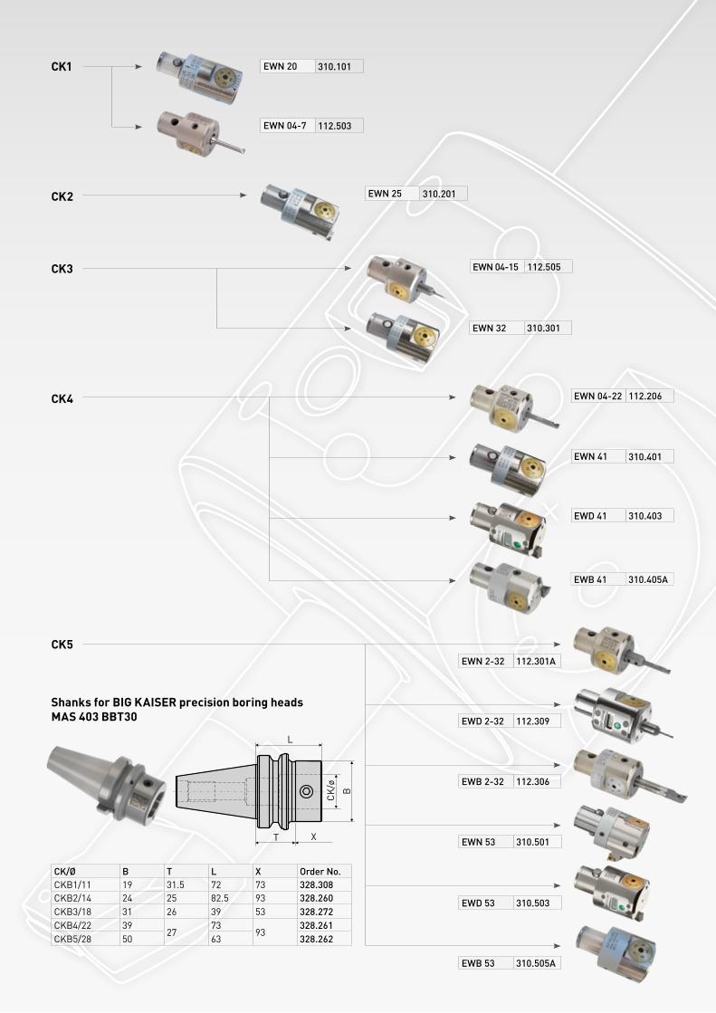
CK
/ø B
Shanks for BIG KAISER precision boring headsMAS 403 BBT30
CK/Ø B T L X Order No.CKB1/11 19 31.5 72 73 328.308CKB2/14 24 25 82.5 93 328.260CKB3/18 31 26 39 53 328.272CKB4/22 39
2773
93328.261
CKB5/28 50 63 328.262
CK1
CK2
CK3
CK4
CK5
EWN 20 310.101
EWN 04-7 112.503
EWN 25 310.201
EWN 04-15 112.505
EWN 32 310.301
EWN 04-22 112.206
EWN 41 310.401
EWD 41 310.403
EWN 53 310.501
EWD 53 310.503
EWB 53 310.505A
EWB 41 310.405A
EWN 2-32 112.301A
EWD 2-32 112.309
EWB 2-32 112.306

BIG KAISER Precision Tooling Ltd. Glattalstrasse 516 | Postfach | CH-8153 Rümlang | T: +41 44 817 92 00 | F: +41 44 817 92 01 | [email protected] | www.bigkaiser.com
Nov
embe
r 20
16
Recommended