Delineation Section 5 – Enhanced delineation devices (Requiring prior approval)
Delineation
Section 5
ENHANCED DELINEATION DEVICES (Requiring prior approval)
Special Note:
As from 17 January 2011, Roads and Maritime Services is adopting the Austroads Guides (Guide to Traffic Management) and Australian Standards (AS 1742, 1743 & 2890) as its primary technical references.
A Roads and Maritime Supplement has been developed for each Part of the Guide to Traffic Management and relevant Australian Standard. The Supplements document any mandatory Roads and Maritime practice and any complementary guidelines which need to be considered.
Roads and Maritime Supplements must be referred to prior to using any reference material.
This Roads and Maritime document is a complementary guideline. Therefore if any conflict arises, the Roads and Maritime Supplements, the Austroads Guides and the Australian Standards are to prevail.
Roads and Maritime Supplements are located on the Roads and Maritime website at www.rms.nsw.gov.au
Version 1.6 UNCONTROLLED WHEN PRINTED

ii Version 1.6
Roads and Maritime Services www.rms.nsw.gov.au
VERSION: 1.6 ISSUED: February 2015
AMENDMENTS: Refer to Amendment Record APPROVED BY: SIGNED SIGNED
Phil Margison Steve Levett General Manager A/General Manager Traffic Management Safer Roads
AUTHORISED FOR USE BY: SIGNED
Michael Bushby Director Network Management
© 2008 Roads and Traffic Authority NSW
Extracts from these guidelines may be reproduced providing the subject is kept in context and the source is acknowledged.
Every effort has been made to supply complete and accurate information. However Roads and Maritime Services, NSW assumes no responsibility for its use.
All trade name references herein are either trademarks or registered trademarks of their respective companies.
For policy and technical enquiries regarding these guidelines please contact:
Journey Management Division Email: [email protected]
To access electronic copies of these and other guidelines go to: http://www.rms.nsw.gov.au/business-industry/partners-suppliers/guidelines/complementary-traffic-material/traffic-transport-technical-manual-documents.html
For the latest amendments (if any) to these guidelines go to: http://www.rms.nsw.gov.au/business-industry/partners-suppliers/guidelines/complementary-traffic-material/delineation.html
ISBN 978-1-921242-89-2 (Electronic only) RTA/Pub. 08.091
UNCONTROLLED WHEN PRINTED

Delineation Section 5 Enhanced delineation devices (Requiring prior approval)
Version 1.6 iii UNCONTROLLED WHEN PRINTED
Contents
5.1 Special Approval ..........................................................................5-1
5.2 Enhanced pavement markings ...................................................5-1
5.2.1 General.................................................................................................................5-1 5.2.2 Enhanced dividing (separation) lines (S3) .....................................................5-1 5.2.3 Enhanced dividing (barrier) lines (BS1, BB1 and BB2) ...............................5-3 5.2.4 Enhanced unbroken lane lines (L5) ................................................................5-6 5.2.5 Enhanced broken profile lane line (L2) .........................................................5-7 5.2.6 Profile linemarking .............................................................................................5-9
5.3 Enhanced lane separation devices ...........................................5-15
5.3.1 General...............................................................................................................5-15 5.3.2 Devices...............................................................................................................5-15 5.3.3 Use ......................................................................................................................5-15
5.4 Delineation devices for tidal flow management.....................5-18
5.4.1 General...............................................................................................................5-18 5.4.2 Devices...............................................................................................................5-18 5.4.3 Use ......................................................................................................................5-20
5.5 Lane Usage Signs .......................................................................5-21
5.5.1 General...............................................................................................................5-21 5.5.2 Use ......................................................................................................................5-21
5.6 Transverse line marking as a perceptual counter measure to
speeding ......................................................................................5-22
5.6.1 General...............................................................................................................5-22 5.6.2 Rumble strips ....................................................................................................5-22 5.6.3 Use ......................................................................................................................5-23
5.7 Enhanced Safety Barrier Delineation ......................................5-26
5.7.1 General...............................................................................................................5-26 5.7.2 Use ......................................................................................................................5-26 5.7.3 Material Requirements....................................................................................5-26 5.7.4 Guidelines ..........................................................................................................5-26 5.7.5 Devices...............................................................................................................5-26

Delineation Section 5 Enhanced delineation devices (Requiring prior approval)
iv Version 1.6 UNCONTROLLED WHEN PRINTED
Figures
Figure 5.1: Enhanced dividing (separation) line (S3)..........................................5-2
Figure 5.2: Enhanced dividing (barrier) line (BS1) .............................................5-5
Figure 5.3: Enhanced dividing (barrier) line (BB1) ............................................5-5
Figure 5.4: Enhanced dividing (barrier) line (BB2) ............................................5-6
Figure 5.5: Enhanced Lane line (L5) .................................................................5-7
Figure 5.6: Profile lane line (L2) ......................................................................5-8
Figure 5.7: Raised ribs across profile linemarking.............................................5-9
Figure 5.8: Type A Profile linemarking...........................................................5-10
Figure 5.9: Type B Profile linemarking ...........................................................5-10
Figure 5.10: Profile line on Motorways and Dual Carriageways ........................5-11
Figure 5.11: Enhanced lane separation devices (Pavement flaps) .......................5-17
Figure 5.12: Enhanced lane separation devices (Collapsible delineator).............5-17
Figure 5.13: Enhanced lane separation devices (Flexible bollards) .....................5-17
Figure 5.14: A typical movable median unit .....................................................5-19
Figure 5.15: Application of Typical Tidal Flow Devices (overhead gantries) ......5-19
Figure 5.16: Application of Typical Tidal Flow Devices (remotely controlled moveable median) ........................................................................5-20
Figure 5.17: Application of Lane Usage Signs (LUS) ..........................................5-22
Figure 5.18: Recommended rumble strip pattern on intersection approach for ≥100 km/h approach speed ..........................................................5-25
Figure 5.19: Application of enhanced Safety Barrier treatment – W Beam ........5-27
Figure 5.20: Application of enhanced Safety Barrier treatment – Concrete Barrier.........................................................................................5-27

Delineation Section 5 Enhanced delineation devices (Requiring prior approval)
Version 1.6 v UNCONTROLLED WHEN PRINTED
Figure 5.21: Application of enhanced Safety Barrier treatment – Central Concrete Barrier.............................................................................................................5-28
Figure 5.22: Dimensions of Yellow Retroreflective Chevron – Central Concrete
Barrier.............................................................................................................5-28
Tables
Table 5.1: Basic Features of Enhanced Dividing Lines.........................................5-3
Table 5.2: Enhanced Dividing (separation & barrier) lines ..................................5-4
Table 5.3: Enhanced Lane Line (L5)...................................................................5-6
Table 5.4: Enhanced Lane Line (L2)...................................................................5-8

Delineation Section 5 Enhanced delineation devices (Requiring prior approval)
vi Version 1.6 UNCONTROLLED WHEN PRINTED
Amendment record Please note that the following updates have been made to this document. Amendment
No Page Description Issued Approved
By 1 5-16 Requirement for approval in 5.3.2
clarified. November
2009 R O’Keefe Mgr Policies & Guidelines
2
5-11
Profile line for other roads deleted
December 2010
R O’Keefe Mgr Traffic Policies, Guidelines & Legislation
3 5-26, 5-27
New Section 5.7 Enhanced Safety Barrier Delineation added
February 2012
R O’Keefe Mgr Traffic Policies, Guidelines & Legislation
4
5-26, 5-27
Width of delineation corrected
March 2012
R O’Keefe Mgr Traffic Policies, Guidelines & Legislation
5 5-26 New Section 5.7.5.3 Enhanced Safety Barrier Delineation – Central Concrete Barrier added.
May 2013
R O’Keefe Mgr Traffic Policies, Guidelines & Legislation
6 5-5 Remove reference to BB3 enhanced barrier line.
February 2015
All Change of name and logos to Roads and Maritime Services (formerly the Roads and Traffic Authority).
Various Update references from General Manager, Traffic Management to Network General Manager NSW.
P McMahon Principal Manager Road Management Policy, Legislation and Local Government

Delineation Section 5 Enhanced delineation devices (Requiring prior approval)
Version 1.6 5-1 UNCONTROLLED WHEN PRINTED
5.1 Special Approval Standard delineation devices should be used on all Roads and Maritime
roads. However, in exceptional circumstances, there may be a case when
enhanced delineation devices may sometimes be needed. Prior approval of
Network General Manager NSW is required for installing enhanced
delineation devices prescribed in this section, except for the use of
perceptual counter measures (Section 5.6), for which approval of the
General Manager, Safer Roads, is also required.
5.2 Enhanced pavement markings
5.2.1 General
The following circumstances may warrant the use of enhanced pavement
markings:
(a) To achieve greater separation between opposing traffic (dividing
line)
(b) To present a more forceful deterrent to changing lanes (unbroken
lane line)
(c) To improve the conspicuity of the painted lines and provide an
enhanced road preview time (all lines)
(d) To control speeding on approaches to a hazard (perceptual
countermeasure)
The enhanced pavement markings do not alter or enhance the legal
significance of the line. These lines provide more forceful visual clues and
/or impart greater separation between opposing traffic.
5.2.2 Enhanced dividing (separation) lines (S3)
5.2.2.1 Description and use
Enhanced dividing (separation) line (S3) is a 200 mm wide broken line as
compared to the 100 mm width of the standard S1 line. It should be used
where greater separation is required between opposing streams of traffic
(See Table 5.1 for separation widths that can be achieved) and where
overtaking is permitted in both directions.

Delineation Section 5 Enhanced delineation devices (Requiring prior approval)
5-2 Version 1.6
Pattern and dimensions of enhanced dividing (separation) lines are shown in
Table 5.2. They are supplemented with a staggered raised pavement
marker pattern (see Section 15 for marker pattern).
5.2.2.2 Guidelines
Enhanced dividing (separation) lines must only be used, where:
(a) Minimum width for a two-lane carriageway is 7 m plus a minimum
width of existing sealed shoulders of 0.5 m each is available, and
(b) AADT volumes are at least 2000 vehicles per day, and
(c) There is demonstrated evidence (supported by crash records) that
the standard S1 line is inadequate in separating opposing traffic.
5.2.2.3 Applications
Application of enhanced dividing line (S3) is illustrated below –
Figure 5.1: Enhanced dividing (separation) line (S3)
UNCONTROLLED WHEN PRINTED

Delineation Section 5 Enhanced delineation devices (Requiring prior approval)
Version 1.6 5-3 UNCONTROLLED WHEN PRINTED
5.2.3 Enhanced dividing (barrier) lines (BS1, BB1 and BB2)
5.2.3.1 Description and use
BS1, BB1 and BB2 lines should be used where greater separation is required
between opposing streams of traffic and overtaking is either restricted or
prohibited. Basic features of enhanced dividing (barrier) lines and separation
widths that can be achieved are given in Table 5.1. The pattern and
dimensions of enhanced dividing (barrier) lines are shown in Table 5.2
Line Type Pattern
Effective separation that can be achieved (RRPM
to RRPM) (Assumes 100mm wide RRPMs)
S3 One broken line 200 mm wide
500 mm
BS1 One unbroken and one broken line 150 mm wide at 150 mm spacing
750 mm
BB1 Two unbroken lines 150 mm wide at 150 mm spacing
750 mm
BB2 Two unbroken lines 200 mm wide at 600 mm spacing
1300 mm
Note: Pattern and dimensions of enhanced dividing (barrier) lines, BS1, BB1 and BB2 are shown in Table 5.2. They are supplemented with Reflective raised pavement markers (RRPMs). Refer to Section 15 for RRPM patterns.
Table 5.1: Basic Features of Enhanced Dividing Lines
Delineation Section 5 Enhanced delineation devices (Requiring prior approval)
5-4 Version 1.6
0.600
Colour
White
W hite
W hite
W hite
0.20
0.150
0.1500.150
9
9
Dimensions (m)
3
3
0.150
9
9
0.150
0.200
0.200
3
0.150
3
Enhanced dividing (barrier) lines strictly in accordancewith the guidelines. Approval needed of GM Traffic Management
Enhanced dividing (barrier) lines strictly in accordancewith the guidelines. Approval needed of GM Traffic Management
Enhanced dividing (barrier) lines strictly in accordancewith the guidelines. Approval needed of GM Traffic Management
UseLineType
B B 1
B B 2
B S1
Enhanced dividing(separation) lines strictly in accordancewith the guidelines. Approval needed of GM Traffic Management
S3
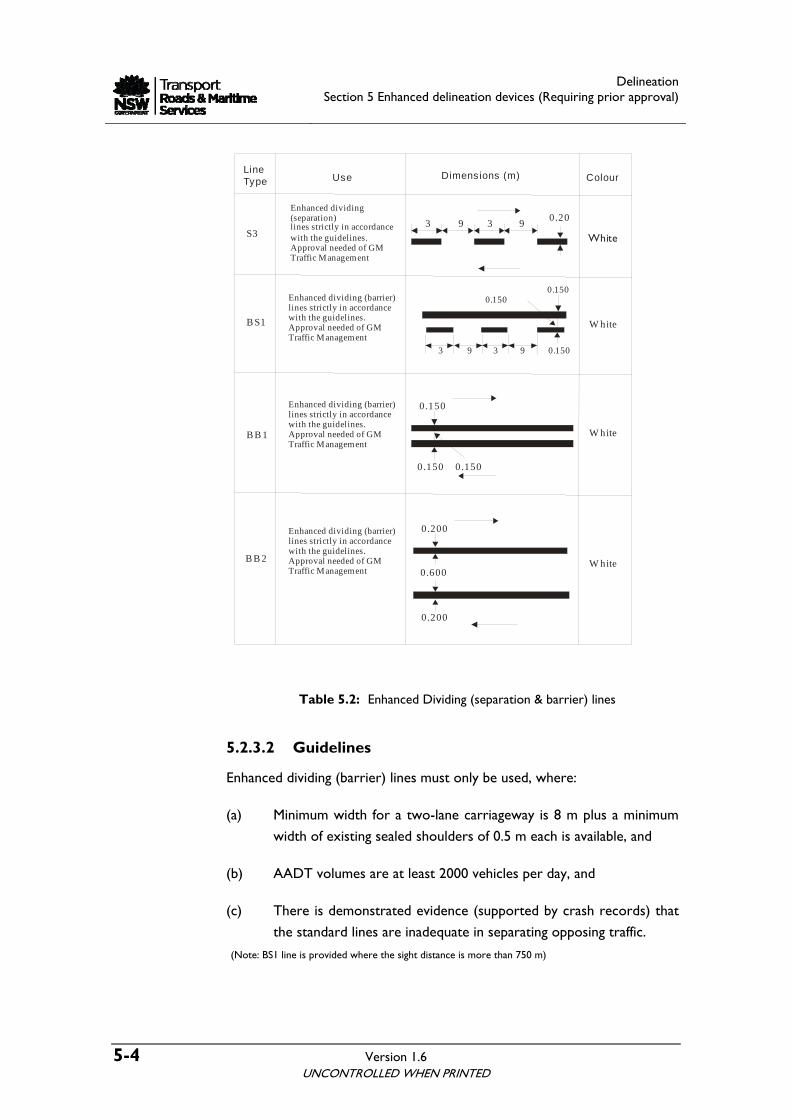
Table 5.2: Enhanced Dividing (separation & barrier) lines
(Note: BS1 line is provided where the sight distance is more than 750 m)
5.2.3.2 Guidelines
Enhanced dividing (barrier) lines must only be used, where:
(a) Minimum width for a two-lane carriageway is 8 m plus a minimum
width of existing sealed shoulders of 0.5 m each is available, and
(b) AADT volumes are at least 2000 vehicles per day, and
(c) There is demonstrated evidence (supported by crash records) that
the standard lines are inadequate in separating opposing traffic.
UNCONTROLLED WHEN PRINTED

Delineation Section 5 Enhanced delineation devices (Requiring prior approval)
Version 1.6 5-5
5.2.3.3 Applications
Application of enhanced dividing lines, BS1, BB1, and BB2 is illustrated
below.
Figure 5.2: Enhanced dividing (barrier) line (BS1)
Figure 5.3: Enhanced dividing (barrier) line (BB1)
UNCONTROLLED WHEN PRINTED

Delineation Section 5 Enhanced delineation devices (Requiring prior approval)
5-6 Version 1.6
Figure 5.4: Enhanced dividing (barrier) line (BB2)
5.2.4 Enhanced unbroken lane lines (L5)
5.2.4.1 Description and use
Enhanced unbroken lane lines shall be 200 mm wide and shall have a
minimum length of 30 m. The pattern and dimensions of enhanced
unbroken lane lines (L5) are shown in Table 5.3.
LineType Use Dimensions (m) Colour
Enhanced lane linestrictly in accordancewith the guidelines. Approval needed of GM Traffic Management
WhiteL50.200
Table 5.3: Enhanced Lane Line (L5)
5.2.4.2 Guidelines
Enhanced unbroken lane lines must only be used, where:
(a) Minimum design lane width is available, and
(b) AADT volumes are at least 2000 vehicles per day, and
(c) There is demonstrated evidence (supported by crash records) that
the standard lines are inadequate in separating opposing traffic.
UNCONTROLLED WHEN PRINTED

Delineation Section 5 Enhanced delineation devices (Requiring prior approval)
Version 1.6 5-7
Examples of locations under (c) could be:
(i) Where, high degree of lane definition is critical to prohibit lane
changing such as inside a tunnel or
(ii) Between through lane and auxiliary lane on freeways at entry and
exit ramps
5.2.4.3 Applications
Application of enhanced unbroken lane line (L5) is illustrated below -
Figure 5.5: Enhanced Lane line (L5)
5.2.5 Enhanced broken profile lane line (L2)
5.2.5.1 Description and use
Enhanced broken profile lane line (L2) is a superior line, compared to
conventional L1 line. Ribs across the line provide enhanced visibility and
audio-tactile warning to motorists to impart better lane discipline. The
pattern and dimensions of enhanced broken profile lane lines (L2) are
shown in Table 5.4. Noise impact must be taken into account when
considering the use of profile linemarking.
Refer to Section 5.2.6 for specifications, drawings, warrants and applications
of these markings.
UNCONTROLLED WHEN PRINTED

Delineation Section 5 Enhanced delineation devices (Requiring prior approval)
5-8 Version 1.6
Table 5.4: Enhanced Lane Line (L2)
5.2.5.2 Guidelines
L2 line shall be used on motorways, dual carriageways; or special locations
such as bridges and tunnels. Earlier a broken simulated line (using non-
reflective raised pavement markers) was used as an L2 lane line. Roads and
Maritime has discontinued its use.
Noise impact must be taken into account when considering the use of
profile linemarking. Refer to Section 5.6 for more details on profile
linemarkings.
5.2.5.3 Applications
Application of enhanced lane line (L2) is illustrated below:
Figure 5.6: Profile lane line (L2)
UNCONTROLLED WHEN PRINTED

Delineation Section 5 Enhanced delineation devices (Requiring prior approval)
Version 1.6 5-9
5.2.6 Profile linemarking
5.2.6.1 General
Profile linemarking is a thermoplastic line, consisting of raised ribs at regular
intervals. These markings provide a more durable marking, enhanced
visibility and an audio-tactile warning to the motorists.
Figure 5.7: Raised ribs across profile linemarking
This section provides guidance on the use of profile linemarking for marking
longitudinal lines while preserving the safe use of roads by all road users
including cyclists, pedestrians and motorcyclists.
5.2.6.2 Benefits
The profile linemarking provides:
(a) An audio-tactile effect to motorists, should they stray from the
carriageway and run onto the marking due to fatigue
(b) Enhanced visibility during adverse weather conditions, especially at
night
5.2.6.3 Types
Currently two different patterns are available, designed to have a raised
profile. They are:
UNCONTROLLED WHEN PRINTED

Delineation Section 5 Enhanced delineation devices (Requiring prior approval)
5-10 Version 1.6
(a) Type A
Formed by mechanically screeding a conventional thermoplastic line and
simultaneously applying transverse ribs of the same thermoplastic material
at a regular interval. This type produces a good audible and tactile effect.
Figure 5.8: Type A Profile linemarking
(b) Type B
Formed by extruding only, transverse ribs, placed directly onto the road
surface. This line produces little audible effect and is intermediate in tactile
effect. This type does provide drainage benefits. Any attempt to apply a
coat of paint to form a continuous line, should be discouraged, if
aquaplaning is a major concern.
The spacing and configuration of ribs can be varied to suit any
requirements, however, 250 mm is considered to be the optimum spacing.
Figure 5.9: Type B Profile linemarking
UNCONTROLLED WHEN PRINTED

Delineation Section 5 Enhanced delineation devices (Requiring prior approval)
Version 1.6 5-11
5.2.6.4 Specifications
The ribs shall be 60 mm ± 10 mm long (measured along the line) with a rib
spacing of 250 mm ± 50 mm. The height of ribs shall be 10 mm ± 2 mm.
10 2 mm
250
mm
60 m
m
±
Figure 5.10: Profile line on Motorways and Dual Carriageways
5.2.6.5 Guidelines
(a) As Lane lines (Only type A)
A broken profile lane line (L2) is used on motorways, dual carriageways; or
special locations such as bridges and tunnels. Refer to Section 5.2.5 for
description, guidelines and application of L2 lines.
Profile lane line may also be used as enhanced lane line (L5). Refer to
Section 5.2.4 for description, guidelines and application of L5 lines.
UNCONTROLLED WHEN PRINTED

Delineation Section 5 Enhanced delineation devices (Requiring prior approval)
5-12 Version 1.6 UNCONTROLLED WHEN PRINTED
(b) As edge lines
(i) Predominantly profile linemarking is recommended for use as an edge
line on motorways or dual carriageways to separate the edge of the sealed
shoulder from the main carriageway. It is particularly useful on sections of
road where drivers are subject to fatigue or sections which experience
frequent foggy conditions. Refer to Section 4.7 for description, guidelines
and application of edge lines
(ii) It should be ensured that:
• Minimum width for a two-lane carriageway is 7 m.
• The shoulder width clear of the edge line is greater than 1.2 m
or 1.5 m adjacent to a guard fence, kerb or other obstacle. This
width requirement does not apply to right hand shoulders on
one-way carriageways.
• AADT volumes are at least 10,000 vehicles per day.
• There is demonstrated evidence (supported by run-off the road
crash records) that the standard lines are inadequate in
discouraging off carriageway vehicles.
(iii) Other road lengths where there is an abnormally high number of
horizontal curves, especially on mountain passes, profile linemarking may be
used as an edge line.
(iv) Profile lines may also be used as an audio-tactile device to guide
motorists where drivers may experience difficulty in following longitudinal
linemarking for example at S-lanes and intersections.
(c) As enhanced dividing lines
(i) Profile linemarking may also be used as enhanced dividing lines to
separate opposing streams of traffic. Refer to Section 5.2.2 and 5.2.3 for
description, guidelines and application of enhanced dividing lines.

Delineation Section 5 Enhanced delineation devices (Requiring prior approval)
Version 1.6 5-13 UNCONTROLLED WHEN PRINTED
(ii) It is particularly useful on sections of road with high a frequency of
head on collisions or where drivers are subject to fatigue or sections, which
experience frequent foggy conditions.
(iii) It should be ensured that:
• Minimum width for a two-lane (two-way) carriageway is 7 m.
• The shoulder width clear of the edge line is greater than 1.2 m
or 1.5 m adjacent to a guard fence, kerb or other obstacle.
• AADT volumes are at least 10,000 vehicles per day.
• There is demonstrated evidence (supported by head-on road
crash records) that the standard lines are inadequate in
separating opposing traffic.
(d) Other applications
(i) Other road lengths where there is an abnormally high number of
horizontal curves, especially on mountain passes, profile linemarking may be
used as an edge line or dividing lines.
(ii) Profile lines may also be used as an audio-tactile device to guide
motorists where drivers may experience difficulty in following longitudinal
linemarking for example at S-lanes and intersections.
(e) Restrictions on use
(i) Use of profile lines requires approval from Network General Manager
NSW.
(ii) As traversing profile linemarking emits an audio-tactile sound, care
should be taken not to install these lines in a noise sensitive area. Profile
lines should not be installed within 500 metres of a residential building
unless appropriate noise barriers are installed, or unless the frequency and
severity of fatigue related crashes in the area are such that a continuous
treatment is considered essential on safety grounds. In such cases, a
distance of 200 metres may be acceptable subject to consultation with the
property owners.

Delineation Section 5 Enhanced delineation devices (Requiring prior approval)
5-14 Version 1.6 UNCONTROLLED WHEN PRINTED
(iii) It should be noted that motorcyclists may not readily distinguish the
profile line from a painted line, and therefore may find this type of
delineation hazardous.
(iv) Profile lines should not be used, if the pavement is scheduled for re-
surfacing or reconstruction within 3 years.
(v) Profile linemarking should be discontinued at defined pedestrian and
bicycle crossings, and replaced by non-profile marking. It would normally
be appropriate to commence the non-profile marking a minimum of 1m
(one) before the crossing and finish a minimum of 1m (one) after the
crossing.
(vi) Profile linemarkings should be replaced with normal continuous
markings in the vicinity of other locations where cyclists are likely to cross
the lines when riding generally parallel to them. Such locations would be
the termination of hard shoulders, and in the vicinity of side road junctions.
In these cases the profile line marking should be replaced by a continuous
marking at least 20 m in advance of the end of any hard shoulder/side road
junction. For merging and diverging lanes the profile line marking should be
replaced 10 m in advance of the merge or diverge lane.
(vii) Where gully pits or similar features occur on the hard shoulders,
cyclists may need to cross the adjacent edge line marking to avoid them.
Any profile line marking adjacent to such features should be replaced by a
normal continuous marking for a distance of 10 m on both sides of the gully
pit.
(viii) Motorcyclists may encounter some discomfort if the profile line
marking was laid on curves of radii less than 1000 m, and motorcyclists
were likely to cross them. It is unlikely that difficulties will occur where
profile linemarkings are provided in conjunction with hard shoulder of 1 m
or less. For a sealed shoulder of 1.5 m or more, profile line-markings
should be replaced by continuous markings if there is any concern that
motorcyclists might frequently cross into the sealed shoulder.

Delineation Section 5 Enhanced delineation devices (Requiring prior approval)
Version 1.6 5-15 UNCONTROLLED WHEN PRINTED
(ix) Drainage gaps should be provided, particularly where the longitudinal
fall is less than 1:150, and there is a cross-fall towards the profile line. The
gap should be 100 mm to 150 mm wide at 36 m intervals.
(x) Where profile linemarking is renewed, care should be taken that the
rib height is not increased above the 6 mm height prescribed. Experience
suggests that the only satisfactory way of renewing is to remove the original
line completely before re-laying. It may also be necessary for drainage
purposes to remove any existing line in the vicinity of a cross fall change
area where the longitudinal fall is less than 1:150, if the final thickness of the
base line is likely to exceed 3 to 4 mm.
5.3 Enhanced lane separation devices
5.3.1 General
Enhanced lane separation devices are a more forceful form of visual
delineation and can also be used to discourage lateral movements (lane
crossing) at potentially hazardous locations. These devices should only be
used in areas where it can be demonstrated through crash records or
erratic traffic manoeuvres that the existing pavement markings and raised
pavement markers are not adequate.
5.3.2 Devices
Pavement flaps, collapsible delineator (e.g. Klemmfix), flexible bollards and
candy bars are used to establish a physical separation between the lanes of
travel. Some of these devices may also be used for tidal flow management
(see Section 5.4).
New products may be used by Roads and Maritime, provided that the
Roads and Maritime Project Manager obtains the approval of Network
General Manager NSW.
5.3.3 Use
Enhanced lane separation devices may be used to provide additional
warning of a painted island on a crest or to control merge movements at a
seagull or similar island arrangement. They may also be used on the
approaches to Toll booths.
Delineation Section 5 Enhanced delineation devices (Requiring prior approval)
5-16 Version 1.6 UNCONTROLLED WHEN PRINTED
Typical uses of arrangements of enhanced lane separation devices are to:
(a) Improve lane control
(b) Supplement dividing (barrier) lines or painted islands where
frequent and hazardous infringements occur
(c) Form an approach treatment to a median or other central
obstruction
5.3.3.1 Guidelines
Enhanced lane separation devices are only prescribed for use to discourage
lateral movements (lane crossing) and should only be used in areas where,
it can be demonstrated through crash records or erratic traffic manoeuvres
that the existing pavement markings and raised pavement markers are not
adequate.
Their use shall be limited to the following:
(a) Where the 85th percentile approach speed is less than 85km/h
(b) The maximum height shall be 1000 mm
(c) Enhanced lane separation devices shall not be installed on two-way
carriageways less than 6.8 m in width and the lane width is less than
3 m
(d) Enhanced lane separation devices should not be installed near well-
defined areas of pedestrian activity or where it is likely to be
hazardous to motorcycle and bicycle riders
(e) Enhanced lane separation devices shall have a retro-reflective
sheeting or delineator. The colour of the retro-reflective material
shall be:
• Yellow when used to supplement dividing line. On collapsible
delineator, yellow sheeting with diagonal hash pattern should be
used.
• White, when used to supplement lane line. On collapsible
delineator, white sheeting with chevron pattern should be used.

Delineation Section 5 Enhanced delineation devices (Requiring prior approval)
Version 1.6 5-17
(f) Preferred spacing for pavement flaps is 3 m and preferred spacing
for collapsible delineator, flexible bollards and candy bars is 12 m,
so as to minimise the possibility of loss of vehicular control if
traversed.
5.3.3.2 Application
Some examples of enhanced lane separation devices are illustrated below.
Figure 5.11: Enhanced lane separation devices (Pavement flaps)
Figure 5.12: Enhanced lane separation devices (Collapsible delineator)
Figure 5.13: Enhanced lane separation devices (Flexible bollards)
UNCONTROLLED WHEN PRINTED

Delineation Section 5 Enhanced delineation devices (Requiring prior approval)
5-18 Version 1.6 UNCONTROLLED WHEN PRINTED
5.4 Delineation devices for tidal flow management
5.4.1 General
Due to the increasing number of vehicles on the network and the
subsequent increase in congestion, there has been a growing need to
improve the efficiency of the existing road system. One method of
enhancing the capacity of the network has been via the use of tidal flow
schemes. Tidal flow schemes allocate more lanes in the direction of the
heaviest traffic flow at certain times of the day.
5.4.2 Devices
5.4.2.1 Manual schemes
5.4.2.1.1 Candy bars
The most common practice is to use candy bars to implement and affect
these manual schemes. These bars are typically made from a hard plastic
material and are used as a delineator. The bars are easily moved to and
from sockets drilled and epoxied into the pavement to establish different
lane configurations. As well as their use in tidal flow applications, candy bars
are used as enhanced lane separation devices at various isolated locations
(refer to Section 5.3).
Preferred spacing of candy bars is 12 m; however, it may be reduced
depending upon the circumstances, e.g. on curves, lateral transitions and
adjacent to side streets subject to turn prohibitions.
5.4.2.1.2 Other devices
Where sockets can not be drilled (e.g. on bridge decks) and where
overhead Lane Use Signs (LUS – see Section 5.5) are not applicable,
pavement flaps or a collapsible delineator may be used.
Manual schemes are labour intensive thus have a higher operating cost.

Delineation Section 5 Enhanced delineation devices (Requiring prior approval)
Version 1.6 5-19
5.4.2.2 Automated schemes
5.4.2.2.1 Movable medians
Partially automated tidal flow systems use a specially designed trailer to shift
solid rubber medians (with reboundable plastic flaps) from one lane to
another (See Figure 5.13). The units are joined together to provide a
continuous separation between opposing directions of traffic.
Some manual intervention is still required.
Figure 5.14: A typical movable median unit
5.4.2.2.2 Other devices
Fully automated electronic systems which comprise in-pavement lights
and/or overhead gantries are also available (see Figure 5.15). More complex
remotely controlled moveable medians are also available (see Figure 5.16).
Figure 5.15: Application of Typical Tidal Flow Devices (overhead gantries)
UNCONTROLLED WHEN PRINTED

Delineation Section 5 Enhanced delineation devices (Requiring prior approval)
5-20 Version 1.6
Figure 5.16: Application of Typical Tidal Flow Devices (remotely controlled moveable median)
5.4.3 Use
Delineation devices for tidal flow management enhance the definition of
dividing line, separating traffic in opposing direction and to discourage
lateral movements (lane crossing).
5.4.3.1 Guidelines
Delineation devices for tidal flow management shall be used:
(a) Where the 85th percentile approach speed is less than 85km/h
(b) The maximum height of the device shall be 1000 mm
(c) Delineation devices for tidal flow management shall not be installed
on two-way carriageways less than 6.8 m in width and the lane
width is less than 3 m
(d) Delineation devices for tidal flow management should not be
installed near well-defined areas of pedestrian activity or where it is
likely to be hazardous to motorcycle and bicycle riders
(e) When using alternate schemes, the basic delineation principles are
still to apply. For example the pavement lights are to be yellow
when installed to separate traffic travelling in opposite directions
and the colour of the retro-reflective sheeting shall be yellow.
(f) The preferred spacing for collapsible delineators, bollards and candy
bars is 12 m, so as to minimise the possibility of loss of vehicular
control if traversed.
UNCONTROLLED WHEN PRINTED

Delineation Section 5 Enhanced delineation devices (Requiring prior approval)
Version 1.6 5-21 UNCONTROLLED WHEN PRINTED
5.5 Lane Usage Signs
5.5.1 General
In addition to or in place of pavement markings, candy bars etc; to separate
opposing traffic and designating lanes for traffic moving in the same
direction in tidal flow and other complex situations, overhead Lane Usage
Signs (LUS) can be used. Locations may be multi-lane bridges and tunnels.
LUS are to be green downward pointing arrows and red crosses. Flashing
red crosses may be used when the direction of traffic in the lane is to be
changed.
5.5.2 Use
The basic aims of these signs are to provide enhanced direction to road
users regarding lane use, convey a clear meaning and give adequate time for
proper response.
5.5.2.1 Guidelines
The length of the bridge or tunnel and the approach speeds would be
important factors in deciding how many and how large and at what spacing
these signs should be placed. As a rough guideline, spacing of
approximately 180 m is suitable in 80Km/h speed environment. The first
sign should be visible from a distance equivalent to decision sight distance
which is 195 m for 60km/h and 280 m for 80km/h approach speed.
They have two states;
(a) Green means lane open (this is the default state).
(b) Red means lane closed – Should be used for an incident that causes
the lane to be unsafe for use or when the lane is being used by
vehicles travelling in the opposite direction. Flashing red crosses are
used to inform motorists of a hazardous situation where the safety
of motorists or maintenance workers is at risk or when the
direction of traffic in the lane is to be changed.

Delineation Section 5 Enhanced delineation devices (Requiring prior approval)
5-22 Version 1.6
5.5.2.2 Application
Some examples of Lane Usage Signs (LUS) are illustrated below.
Figure 5.17: Application of Lane Usage Signs (LUS)
5.6 Transverse line marking as a perceptual counter measure to speeding
5.6.1 General
Traditional regulatory measures used to control speed are typically setting
speed limits and enforcing them. Traffic calming efforts such as speed
humps, roundabouts, and pavement textures are also used to encourage
road users to reduce their speeds, especially in residential areas.
An alternative way to reduce excessive speeds is to target speed
perception, one basic aspect of the driving task. Perceptual
countermeasures serve to alter drivers’ perceptions of the correct speed
for a particular road so drivers may assume a lower speed is more
appropriate. While regulatory measures require enforcement, traffic
calming and passive speed control measures are intended to be self-
enforcing.
Use of perceptual counter measures requires approval of the General
Manager Safer Roads.
5.6.2 Rumble strips
Transverse road markings, placed across the road rather than down the
side, can be used to alter speeds by modifying drivers’ perception. The
transverse marking most commonly used is a ‘polymer modified binder
UNCONTROLLED WHEN PRINTED

Delineation Section 5 Enhanced delineation devices (Requiring prior approval)
Version 1.6 5-23 UNCONTROLLED WHEN PRINTED
(PMB) spray seal’ strip (refer to Section 5.6.4.2 for details). This marking
pattern may be an effective measure for reducing speeds when placed at
decreasing distances so the spacing between markings is continuously
reduced in the direction of movement. This layout of markings creates the
illusion of acceleration that would cause the driver to slow down. The idea
is to space the lines in such a way that the driver who failed to slow would
see the transverse lines at an increasing rate and when the driver
decelerates appropriately, the lines would move past at a constant rate.
5.6.3 Use
Rumble strips are not recommended for extensive use. They should only be
used as an alerting device to address a road safety problem where other
conventional measures such a signing and road markings have proven to be
ineffective, and change to geometric layout is not possible.
Rumble strips alone should not be used as a traffic management device for
the control of speeds. It is recommended that installation of the rumble
strips should be accompanied by appropriate signing to convey the nature
of the potential hazard, and hence communicate the reason for the
installation to drivers.
5.6.3.1 Guidelines
Before deciding to use rumble strips, it is recommended that the following
signing options should be considered:
(a) Increased level of signing on the approaches by duplicating the
recommended signs on both sides of the road.
(b) Provision of edge lines.
(c) Installation of retroreflective raised pavement markers to
supplement separation lines and edge lines.
(d) Increased size of the recommended signs (and hazard markers
where applicable).
(e) Use of “REDUCE SPEED” signs. These should only be used where
there is considerable danger to the motorist if this sign is
disobeyed.
The above measures may be combined to achieve the desired level of
warning. If the highest practicable level of signing still fails to produce a

Delineation Section 5 Enhanced delineation devices (Requiring prior approval)
5-24 Version 1.6 UNCONTROLLED WHEN PRINTED
satisfactory result, the installation of rumble strips may be considered in
conjunction with a high level of signing.
A high level of signing alone is generally more effective and less expensive
than low level signing with rumble strips.
5.6.4.1 Spacing
The spacing generally used is that of a converging pattern of transverse
strips placed such that a decelerating vehicle will strike the strips at a
constant time interval of not less than 0.5 second. It is recommended that
pattern of up to 10 strips should be used such that a strip is struck each
second whilst decelerating at a comfortable rate. Figure 5.18 shows the
pattern for 100 km/h, 80km/h and 60 km/h approach speeds.
It should be noted that these are example patterns only. Other patterns
may be considered for approval.
5.6.4.2 Strip Dimensions
It is considered that the strip widths should not be less than the average car
axle spacing. The recommended widths are shown in Figure 5.18.
The height of strips is generally 10-20 mm and they are usually constructed
by a polymer modified binder (PMB) spray seal on the existing pavement. It
is recommended that the last 15-30 m prior to the stop or give way line
should be continuously treated with the same rough textured material used
for the rumble strips (asphalt or recycled rubber) to provide a rough
surface on which to decelerate quickly should braking occur too late.

Delineation Section 5 Enhanced delineation devices (Requiring prior approval)
Version 1.6 5-25
Figure 5.18: Recommended rumble strip pattern on intersection approach for ≥100 km/h approach speed
Notes – (i) Figure shown is for ≥100 km/h approach speed environment (ii) For <100 km/h to ≥80 km/h do not provide strip numbers 1 and 2; anti-skid
surface length 20 to 30 m (iii) For <80 km/h to ≥60 km/h do not provide strip numbers 1 to 4; antiskid surface
length 15 to 20 m.
UNCONTROLLED WHEN PRINTED

Delineation Section 5 Enhanced delineation devices (Requiring prior approval)
5-26 Version 1.6 UNCONTROLLED WHEN PRINTED
5.7 Enhanced Safety Barrier Delineation
5.7.1 General
Safety Barriers are designed to protect vehicles from roadside hazards and
to safely redirect the errant vehicle. Under some circumstances the lack of
conspicuity or the road geometry can transform a barrier it into a roadside
hazard and under these circumstances warrant the use of enhanced
delineation.
5.7.2 Use
The basic aims of these treatments are to improve the conspicuity of the
Safety Barrier by providing enhanced delineation and hence crash avoidance.
This enhanced treatment should only be used in areas where it can be
demonstrated through crash records or erratic traffic manoeuvres that the
existing Safety Barrier delineation is not adequate.
Use of Enhanced Safety Barrier Delineation requires approval of the
General Manager Traffic and Safety Management.
5.7.3 Material Requirements.
The enhanced Safety Barrier delineation shall be yellow 150mm wide
waterborne high durability marking paint (with 1.9 Index Glass Beads). It
shall be designed to resist sagging and with superior adhesion to the surface
of concrete and galvanised safety barriers.
5.7.4 Guidelines
Enhanced Safety Barrier delineation shall be continuous. Length of
treatment required shall be decided on-site.
5.7.5 Devices
5.7.5.1 W Beam application
Enhanced Safety Barrier Delineation shall be 150mm wide applied centrally
within the concave area of W beam.

Delineation Section 5 Enhanced delineation devices (Requiring prior approval)
Version 1.6 5-27
Figure 5.19: Application of enhanced Safety Barrier treatment – W Beam
5.7.5.2 Concrete Barrier application – non-central barrier
Enhanced Safety Barrier Delineation shall be 150mm wide applied 200mm ±
50mm from the top of the barrier.
Figure 5.20: Application of enhanced Safety Barrier treatment – Non-Central Concrete Barrier
5.7.5.3 Concrete Barrier application - central barrier
Enhanced Central Concrete Safety Barrier Delineation shall be:
• For curve advisory speeds less than 50km/h, yellow painted
retroreflective chevrons as per Figure 5.22, 300mm wide, 1500mm
long, 1500mm ± 50mm gap, applied 100mm ± 50mm from the top
of the barrier. Length shall be from curve tangent point to curve
UNCONTROLLED WHEN PRINTED

Delineation Section 5 Enhanced delineation devices (Requiring prior approval)
5-28 Version 1.6
tangent point and two extra chevrons shall be placed before and
after the curve tangent points
• For curve advisory speeds greater than 50km/h, yellow painted
retroreflective chevrons as per Figure 5.22, 300mm wide, 1500mm
long, 3000mm± 50mm gap, applied 100mm ± 50mm from the top
of the barrier. Length shall be from curve tangent point to curve
tangent point and two extra chevrons shall be placed before and
after the curve tangent points
Use of Curve Alignment Markers (CAM’s) may no longer be required after
treatment of central barrier. Decision shall be made on-site.
Figure 5.21: Application of enhanced Safety Barrier treatment – Central Concrete
Barrier
300 ± 30mm
1500 ± 50mm
160 ± 10mm 160 ± 10mm
150 ± 10mm
Figure 5.22: Dimensions of Yellow Painted Retroreflective Chevron
Central Concrete Barrier.
UNCONTROLLED WHEN PRINTED

For further enquiries www.rta.nsw.gov.au 13 22 13
Roads and Traffic Authority March 2008 RTA/Pub. 08.091
Recommended