www.deltapowersolutions.com 1 / 4
Delta UPS - Amplon Family N Series, Single Phase
6/ 10 kVA Maintenance Bypass Box
for Single UPS & Parallel UPSs
Installation & Operation Quick Guide
ENGLISH
Product Introduction1
The Maintenance Bypass Box is designed to operate in conjunction with your Delta N series 6kVA/ 10kVA UPS. It ensures that your connected critical load continues to be powered from the input supply during UPS maintenance or during the unlikely event of a UPS failure.
Important Safety Instructions2
yy Only qualified service personnel can perform installation and maintenance of the Main-tenance Bypass Box.
yy The Maintenance Bypass Box must operate in conjunction with Delta N series 6kVA/ 10kVA UPS. Please refer to the following table.
Maintenance Bypass Box Model
PDB1511A530035(for single UPS application)
PDB1512A510035(for parallel UPSs application)
Applicable Delta N series UPS Model
UPS103N2002N009UPS103N2004N0B0UPS103N2004N0BAUPS103N2004N035UPS602N2002N009UPS602N2004N0B0UPS602N2004N0BAUPS602N2004N035
UPS103N2004N0B0UPS103N2004N0BAUPS103N2004N035UPS602N2004N0B0UPS602N2004N0BAUPS602N2004N035
yy Before installation of the Maintenance Bypass Box, please completely turn off the UPS and cut off the input power and battery power (if applicable).
yy Failure to properly install the Maintenance Bypass Box may result in severe damage to your UPS or load equipment.
yy Please install the Maintenance Bypass Box in an indoor temperature controlled environ-ment that is free of conductive contaminants.
yy Do not operate the unit in extremely dusty and/ or unclean areas, locations near heating devices, water or excessive humidity, or where the unit is exposed to direct sunlight.
yy Select a location where provides good air circulation for the unit at all times.
yy Properly route power cords so they cannot be walked on or damaged.
yy The Maintenance Bypass Box must be well grounded due to a possible risk of current leakage.
yy The Maintenance Bypass Box is not intended for use in direct patient care or in life sup-port applications.
Package List3
yy Model PDB1511A530035_ Maintenance Bypass Box for Single UPS Application21
8
53 4
9 106
7
No. Item Q'ty1 CU Terminal (Type A) 4 PCS2 CU Terminal (Type B) 4 PCS3 Terminal Holder 2 PCS4 Screw for Fastener 8 PCS5 Fastener (Type A) 4 PCS6 Wire 1 1 PCS7 Wire 2 1 PCS8 Cable Tie 6 PCS9 Screw for Terminal Holder 2 PCS
10 RS-232 Cable 1 PCS
yy Model PDB1512A510035_ Maintenance Bypass Box for Parallel UPSs Application
2 651
1110
3
1312
74
8
9
No. Item Q'ty1 Heat Shrink Tube 12 PCS2 CU Terminal (Type B) 4 PCS3 CU Terminal (Type C) 6 PCS4 Terminal Holder 4 PCS5 Screw for Fastener 12 PCS6 Fastener (Type A) 4 PCS7 Fastener (Type B) 1 PCS8 Wire 1 2 PCS9 Wire 2 2 PCS
10 Cable Tie 6 PCS
11 Cable Gland 2 PCS
12 Screw for Terminal Holder 4 PCS
13 Parallel Cable 1 PCS
NOTE:1. If there is any damage or anything missing, please immediately contact the
dealer from whom you purchased the unit.2. If the Maintenance Bypass Box needs to be returned, carefully repack the
Maintenance Bypass Box and all of the accessories using the original packing material that came with the unit.
Standard Compliance4
yy IEC
yy EN62040-1
How to Remove the Front Panel5
输出断路器
OUTPUT BREAKER
ONOFF
旁路开关BYPASS SWITCH
旁路断路器
UPS1 输出断路器
UPS1 OUTPUT BREAKER
UPS2 输出断路器
UPS2 OUTPUT BREAKER OFF
ON
OFF
ON
BYPASS BREAKER
警告
:开起
此盖
板时
,会即
刻关
闭逆
变器
输出
.非授
权合
格人
员,严
禁开
起.
W A RN IN G :
OP E N IN G T H IS CO VER PL ATE W ILL
CAUSE IN V E R T E R SHU TD OW N. ON LY
AU TH OR I ZE D S E R V IC E P E R S ON NEL
CAN O P E N A N D OP E R A TE IT .
警告
:开起
此盖
板时
,会即
刻关
闭逆
变器
输出
.非授
权合
格人
员,严
禁开
起.
W A RN IN G :
OP E N IN G T H IS CO VER PL ATE W ILL
CAUSE IN V E R T E R S H U TD OW N. ON LY
AU TH OR I ZE D S E R V IC E P E R S ON NEL
CAN O P E N A N D OP E R A TE IT .
Remove the Front Panel
Pull Pull
Remove the Front Panel
PDB1512A510035PDB1511A530035
Front View after Front Panel Removal6
yy PDB1511A530035
OFFON
BYPASS SWITCH旁路开关
输出断路器OUTPUT BREAKER警 告 :
开 起 此 盖 板 时 , 会 即 刻 关 闭 逆 变 器 输 出 . 非 授权 合 格 人 员 , 严 禁 开 起 .
W A R N IN G :O P E N I N G T H I S C O V E R P L A T E W I L LC A U S E I N V E R T E R S H U T D O W N . O N L YA U T H O R I Z E D S E R V I C E P E R S O N N E LC A N O P E N A N D O P E R A T E I T .
2
1
5
4
3
No. Item
1 Latch (for fastening the front panel)
2 Latch (for fastening the front panel)
3 Bypass Switch (please remove the cover’s screw shown in the figure above to see the bypass switch)
4 Output Breaker
5 Latch (for fastening the front panel)
yy PDB1512A510035
旁路断路器
UPS2 输出断路器UPS2 OUTPUT BREAKER
UPS1 输出断路器UPS1 OUTPUT BREAKER
BYPASS BREAKER
OFFON
OFFON
警 告 : 开 起 此 盖 板 时 , 会 即 刻 关 闭 逆 变 器 输 出 . 非授 权 合 格 人 员 , 严 禁 开 起 .
W A R N IN G :O P E N I N G T H I S C O V E R P L A T E W I L LC A U S E I N V E R T E R S H U T D O W N . O N L YA U T H O R I Z E D S E R V I C E P E R S O N N E LC A N O P E N A N D O P E R A T E I T .
1
2
3 4 5 6
No. Item
1 Latch (for fastening the front panel)
2 Latch (for fastening the front panel)
3 UPS2 Output Breaker
Continue to the Next Page 5013246101
www.deltapowersolutions.com 2 / 4
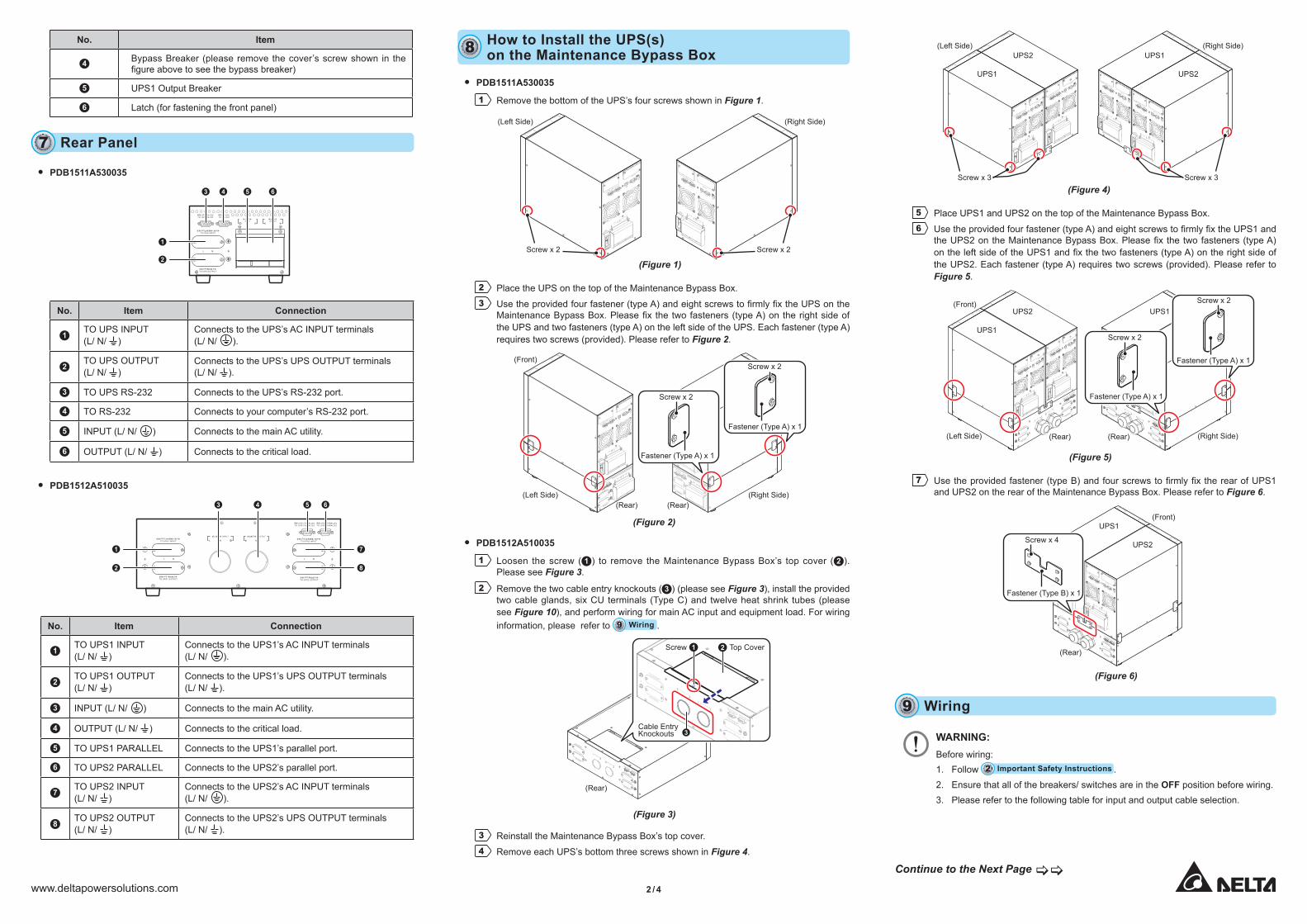
No. Item
4 Bypass Breaker (please remove the cover’s screw shown in the figure above to see the bypass breaker)
5 UPS1 Output Breaker
6 Latch (for fastening the front panel)
Rear Panel7
yy PDB1511A530035
NL N L
L N
连 接 UPS主 电 源 输 入 端 子 排
TO UPS INPUT
连 接 UPS输 出端 子 排
TO UPS OUTPUT
UPS RS-232连 接UPS RS-232TO
RS-232连 接RS-232TO
输 入 端 子 排INPUT
输 出端 子 排OUTPUT
1
2
43 5 6
No. Item Connection
1TO UPS INPUT (L/ N/ )
Connects to the UPS’s AC INPUT terminals (L/ N/ ).
2TO UPS OUTPUT (L/ N/ )
Connects to the UPS’s UPS OUTPUT terminals (L/ N/ ).
3 TO UPS RS-232 Connects to the UPS’s RS-232 port.
4 TO RS-232 Connects to your computer’s RS-232 port.
5 INPUT (L/ N/ ) Connects to the main AC utility.
6 OUTPUT (L/ N/ ) Connects to the critical load.
yy PDB1512A510035
连 接 UPS1主 电 源 输 入 端 子 排
TO UPS1 INPUT
连 接 UPS1输 出端 子 排
TO UPS1 OUTPUT
连 接 UPS2主 电 源 输 入 端 子 排
TO UPS2 INPUT
连 接 UPS2输 出端 子 排
TO UPS2 OUTPUT
UPS1 PARALLEL连 接UPS1 PARALLELTO
UPS2 PARALLEL连 接UPS2 PARALLELTO
L N L N
NL
输 入 端 子 排 INPUT
N L
输 出端 子 排 OUTPUT
1
2
7
8
43 5 6
No. Item Connection
1TO UPS1 INPUT (L/ N/ )
Connects to the UPS1’s AC INPUT terminals (L/ N/ ).
2TO UPS1 OUTPUT (L/ N/ )
Connects to the UPS1’s UPS OUTPUT terminals (L/ N/ ).
3 INPUT (L/ N/ ) Connects to the main AC utility.
4 OUTPUT (L/ N/ ) Connects to the critical load.
5 TO UPS1 PARALLEL Connects to the UPS1’s parallel port.
6 TO UPS2 PARALLEL Connects to the UPS2’s parallel port.
7TO UPS2 INPUT (L/ N/ )
Connects to the UPS2’s AC INPUT terminals (L/ N/ ).
8TO UPS2 OUTPUT (L/ N/ )
Connects to the UPS2’s UPS OUTPUT terminals (L/ N/ ).
How to Install the UPS(s)on the Maintenance Bypass Box8
yy PDB1511A530035
1 Remove the bottom of the UPS’s four screws shown in Figure 1.
(Figure 1)
INPUT
BREAKER
UPS OUTPUT
N
N
L
L
AC INPUT
RS-232
REPO
PARALLEL
PARALLEL
SMART SLOT
EXTERNAL BATT. CONNECTOR 192Vdc.58A
INPUT BREAKER
UPS OUTPUT
N N
L
L
AC INPUT
RS-232
REPO
PARALLEL
PARALLEL
SMART SLOT
EXTERNAL BATT. CONNECTOR 192Vdc.58A
(Left Side)
Screw x 2
(Right Side)
Screw x 2
2 Place the UPS on the top of the Maintenance Bypass Box.3 Use the provided four fastener (type A) and eight screws to firmly fix the UPS on the
Maintenance Bypass Box. Please fix the two fasteners (type A) on the right side of the UPS and two fasteners (type A) on the left side of the UPS. Each fastener (type A) requires two screws (provided). Please refer to Figure 2.
(Figure 2)
INPUT
BREAKER
UPS OUTPUT
N
N
L
L
AC INPUT
RS-232
REPO
PARALLEL
PARALLEL
SMART SLOT
EXTERNAL BATT. CONNECTOR 192Vdc.58A
L
N
连接
UPS主电
源输
入端
子排
TO UPS IN
PUT
连接
UPS输出端
子排
TO UPS O
UTPUT
N
L
N
L
UPS RS-232
连接
UPS RS-232
TO
RS-232
连接
RS-232
TO
输入
端子
排
INPUT
输出端
子排
OUTPUT
INPUT BREAKER
UPS OUTPUT
N N
L
L
AC INPUT
RS-232
REPO
PARALLEL
PARALLEL
SMART SLOT
EXTERNAL BATT. CONNECTOR 192Vdc.58A
L N
连接 UPS主
电源
输入
端子
排
TO UPS INPUT
连接 UPS输
出端
子排
TO UPS OUTPUT
N
L
N
L
UPS RS-232
连接
UPS RS-232
TO
RS-232
连接
RS-232
TO
输入
端子
排INPUT
输出
端子
排OUTPUT
Fastener (Type A) x 1
(Rear) (Rear)
(Front)
Screw x 2
Fastener (Type A) x 1
Screw x 2
(Left Side) (Right Side)
yy PDB1512A510035
1 Loosen the screw ( 1 ) to remove the Maintenance Bypass Box’s top cover ( 2 ). Please see Figure 3.
2 Remove the two cable entry knockouts ( 3 ) (please see Figure 3), install the provided two cable glands, six CU terminals (Type C) and twelve heat shrink tubes (please see Figure 10), and perform wiring for main AC input and equipment load. For wiring information, please refer to Wiring9 .
(Figure 3)
L N
连接 UPS2主
电源
输入
端子
排
TO UPS2 INPUT
连接 UPS2输
出端子
排
TO UPS2 OUTPUT
UPS1 PARALLEL
连接
UPS1 PARALLEL
TO
UPS2 PARALLEL
连接
UPS2 PARALLEL
TO
L N
连接 UPS1主
电源
输入
端子
排
TO UPS1 INPUT
连接 UPS1输
出端子
排
TO UPS1 OUTPUT
N
L输
入端
子排
INPUT
N
L
输出
端子
排OUTPUT
(Rear)
L N
连接 UPS2主
电源
输入
端子
排
TO UPS2 INPUT
连接 UPS2输
出端子
排
TO UPS2 OUTPUT
UPS1 PARALLEL
连接
UPS1 PARALLEL
TO
UPS2 PARALLEL
连接
UPS2 PARALLEL
TO
L N
连接 UPS1主
电源
输入
端子
排
TO UPS1 INPUT
连接 UPS1输
出端子
排
TO UPS1 OUTPUT
N
L输
入端
子排
INPUT
N
L
输出
端子
排OUTPUT
3
2 Top CoverScrew
Cable EntryKnockouts
1
3 Reinstall the Maintenance Bypass Box’s top cover.4 Remove each UPS’s bottom three screws shown in Figure 4.
(Figure 4)
INPUT
BREAKER
UPS OUTPUT
N
N
L
L
AC INPUT
RS-232
REPO
PARALLEL
PARALLEL
SMART SLOT
EXTERNAL BATT. CONNECTOR 192Vdc.58A
INPUT
BREAKER
UPS OUTPUT
N
N
L
L
AC INPUT
RS-232
REPO
PARALLEL
PARALLEL
SMART SLOT
EXTERNAL BATT. CONNECTOR 192Vdc.58A
INPUT BREAKER
UPS OUTPUT
N N
L
L
AC INPUT
RS-232
REPO
PARALLEL
PARALLEL
SMART SLOT
EXTERNAL BATT. CONNECTOR 192Vdc.58A
INPUT BREAKER
UPS OUTPUT
N N
L
L
AC INPUT
RS-232
REPO
PARALLEL
PARALLEL
SMART SLOT
EXTERNAL BATT. CONNECTOR 192Vdc.58A
(Left Side)
UPS1
UPS2 UPS1
UPS2
Screw x 3
(Right Side)
Screw x 3
5 Place UPS1 and UPS2 on the top of the Maintenance Bypass Box.6 Use the provided four fastener (type A) and eight screws to firmly fix the UPS1 and
the UPS2 on the Maintenance Bypass Box. Please fix the two fasteners (type A) on the left side of the UPS1 and fix the two fasteners (type A) on the right side of the UPS2. Each fastener (type A) requires two screws (provided). Please refer to Figure 5.
(Figure 5)
INPUT BREAKER
UPS OUTPUT
N N
L
L
AC INPUT
RS-232
REPO
PARALLEL
PARALLEL
SMART SLOT
EXTERNAL BATT. CONNECTOR 192Vdc.58A
INPUT BREAKER
UPS OUTPUT
N N
L
L
AC INPUT
RS-232
REPO
PARALLEL
PARALLEL
SMART SLOT
EXTERNAL BATT. CONNECTOR 192Vdc.58A
L N
连接 UPS2主
电源
输入
端子
排
TO UPS2 INPUT
连接 UPS2输
出端子
排
TO UPS2 OUTPUT
UPS1 PARALLEL
连接
UPS1 PARALLEL
TO
UPS2 PARALLEL
连接
UPS2 PARALLEL
TO
L N
连接 UPS1主
电源
输入
端子
排
TO UPS1 INPUT
连接 UPS1输
出端子
排
TO UPS1 OUTPUT
N
L输
入端
子排
INPUT
N
L
输出
端子
排OUTPUT
INPUT
BREAKER
UPS OUTPUT
N
N
L
L
AC INPUT
RS-232
REPO
PARALLEL
PARALLEL
SMART SLOT
EXTERNAL BATT. CONNECTOR 192Vdc.58A
INPUT
BREAKER
UPS OUTPUT
N
N
L
L
AC INPUT
RS-232
REPO
PARALLEL
PARALLEL
SMART SLOT
EXTERNAL BATT. CONNECTOR 192Vdc.58A
L
N
连接
UPS2主电
源输
入端
子排
TO UPS2 IN
PUT
连接
UPS2输出
端子
排
TO UPS2 O
UTPUT
UPS1 PARALLEL
连接 UPS1 P
ARALLEL
TO
UPS2 PARALLEL
连接 UPS2 P
ARALLEL
TO
L
N
连接
UPS1主电
源输
入端
子排
TO UPS1 IN
PUT
连接
UPS1输出
端子
排
TO UPS1 O
UTPUT
N
L
输入
端子
排IN
PUT
N
L
输出
端子
排OUTPUT
Fastener (Type A) x 1
(Rear) (Rear)
(Front)
Screw x 2
Fastener (Type A) x 1
Screw x 2
(Left Side) (Right Side)
UPS1
UPS2 UPS1
7 Use the provided fastener (type B) and four screws to firmly fix the rear of UPS1 and UPS2 on the rear of the Maintenance Bypass Box. Please refer to Figure 6.
(Figure 6)
INPUT BREAKER
UPS OUTPUT
N N
L
L
AC INPUT
RS-232
REPO
PARALLEL
PARALLEL
SMART SLOT
EXTERNAL BATT. CONNECTOR 192Vdc.58A
INPUT BREAKER
UPS OUTPUT
N N
L
L
AC INPUT
RS-232
REPO
PARALLEL
PARALLEL
SMART SLOT
EXTERNAL BATT. CONNECTOR 192Vdc.58A
L N
连接 UPS2主
电源
输入
端子
排
TO UPS2 INPUT
连接 UPS2输
出端子
排
TO UPS2 OUTPUT
UPS1 PARALLEL
连接
UPS1 PARALLEL
TO
UPS2 PARALLEL
连接
UPS2 PARALLEL
TO
L N
连接 UPS1主
电源
输入
端子
排
TO UPS1 INPUT
连接 UPS1输
出端子
排
TO UPS1 OUTPUT
N
L输
入端
子排
INPUT
N
L
输出
端子
排OUTPUT
Fastener (Type B) x 1
Screw x 4
UPS1
UPS2
(Rear)
(Front)
Wiring9
WARNING: Before wiring:1. Follow Important Safety Instructions2 .2. Ensure that all of the breakers/ switches are in the OFF position before wiring.3. Please refer to the following table for input and output cable selection.
Continue to the Next Page

www.deltapowersolutions.com 3 / 4
yy PDB1511A530035:
Temperature Rating 6kVA 10kVA60°C / 75°C # 8AWG / 6mm2 (Cu) # 6AWG / 10mm2 (Cu)
yy PDB1512A510035:
Temperature Rating 12kVA 20kVA60°C / 75°C # 4AWG / 16mm2 (Cu) 35mm2
1 Please see Figure 7 for a general concept of wiring.
(Figure 7)
ONOFF
SMART SLOT
RS-232 REPOREPOPARALLEL PARALLEL
INPUT BREAKER
UPS OUT PUT
N N L L
AC INPUT
EXTERNAL BATT. CONNECTOR 192Vdc.58A
ONOFF
SMART SLOT
RS-232 REPOREPOPARALLEL PARALLEL
INPUT BREAKER
UPS OUT PUT
N N L L
AC INPUT
EXTERNAL BATT. CONNECTOR 192Vdc.58A
ONOFF
SMART SLOT
RS-232 REPOREPOPARALLEL PARALLEL
INPUT BREAKER
UPS OUT PUT
N N L L
AC INPUT
EXTERNAL BATT. CONNECTOR 192Vdc.58A
NL N L
L N
连 接 UPS输 出端 子 排
TO UPS OUTPUT
输 入 端 子 排INPUT
输 出端 子 排OUTPUT
连 接 UPS1主 电 源 输 入 端 子 排
TO UPS1 INPUT
连 接 UPS1输 出端 子 排
TO UPS1 OUTPUT
连 接 UPS2主 电 源 输 入 端 子 排
TO UPS2 INPUT
连 接 UPS2输 出端 子 排
TO UPS2 OUTPUT
UPS1 PARALLEL连 接UPS1 PARALLELTO
UPS2 PARALLEL连 接UPS2 PARALLELTO
L N L N
NL
输 入 端 子 排 INPUT
N L
输 出端 子 排 OUTPUT
连 接 UPS主 电 源 输 入 端 子 排
TO UPS INPUT
UPS RS-232连 接
UPS RS-232TORS-232连 接
RS-232TO
PDB1512A510035PDB1511A530035(Rear) (Rear)
Connects to AC Utility
Connects to Critical Load
Connects to AC Utility
Connects to Critical Load
2 Remove all of the cover plates’ screws and the cable entry knockouts shown in Figure 8.
(Figure 8)
连 接 UPS1主 电 源 输 入 端 子 排
TO UPS1 INPUT
连 接 UPS1输 出端 子 排
TO UPS1 OUTPUT
连 接 UPS2主 电 源 输 入 端 子 排
TO UPS2 INPUT
连 接 UPS2输 出端 子 排
TO UPS2 OUTPUT
UPS1 PARALLEL连 接UPS1 PARALLELTO
UPS2 PARALLEL连 接UPS2 PARALLELTO
L N L N
NL
输 入 端 子 排 INPUT
N L
输 出端 子 排 OUTPUTNL N L
L N
连 接 UPS输 出端 子 排
TO UPS OUTPUT
输 入 端 子 排INPUT
输 出端 子 排OUTPUT
连 接 UPS主 电 源 输 入 端 子 排
TO UPS INPUT
UPS RS-232连 接UPS RS-232TO
RS-232连 接RS-232TO
(Rear) (Rear)
PDB1512A510035PDB1511A530035
Screw x 6 Screw x 8Cable EntryKnockout x 2
3 Follow Figure 9 and Figure 10 to install the provided accessories on the Mainten-ance Bypass Box and perform wiring.
yy PDB1511A530035
L N
连 接 UPS输 出端 子 排
TO UPS OUTPUT
NL N L
L N
输 入 端 子 排INPUT
输 出端 子 排OUTPUT
连 接 UPS主 电 源 输 入 端 子 排
TO UPS INPUT
UPS RS-232连 接UPS RS-232TO
RS-232连 接RS-232TO
CU Terminal(Type A) x 4
CU Terminal(Type B) x 3
CU Terminal(Type B) x 1
Wire 1 x 1 & Terminal Holder x 1 & Screw x 1
Wire 2 x 1 & Terminal Holder x 1 & Screw x 1
+ + =
+ + =
(Figure 9)
yy PDB1512A510035
连 接 UPS1主 电 源 输 入 端 子 排
TO UPS1 INPUT
连 接 UPS1输 出端 子 排
TO UPS1 OUTPUT
连 接 UPS2主 电 源 输 入 端 子 排
TO UPS2 INPUT
连 接 UPS2输 出端 子 排
TO UPS2 OUTPUT
UPS1 PARALLEL连 接UPS1 PARALLELTO
UPS2 PARALLEL连 接
UPS2 PARALLELTO
L N L N
NL
输 入 端 子 排 INPUT
N L
输 出端 子 排 OUTPUT
CU Terminal(Type B) x 2
CU Terminal(Type B) x 2
UPS 1 : Wire 1 x 1 & Terminal Holder x 1 & Screw x 1UPS 2 : Wire 1 x 1 & Terminal Holder x 1 & Screw x 1
UPS 1 : Wire 2 x 1 & Terminal Holder x 1 & Screw x 1UPS 2 : Wire 2 x 1 & Terminal Holder x 1 & Screw x 1
+
+
Cable Glandx 1
CU Terminal (Type C) x 3
Heat ShrinkTube x 6
Cable Glandx 1
CU Terminal (Type C) x 3
Heat ShrinkTube x 6
+ + =
+ + =
(Figure 10)
Start-up Operation10
yy PDB1511A530035All the equipment and the UPS system must be properly connected and there must be an acceptable AC voltage present. Please refer to the UPS’s user manual for more information.
NOTE:The cover plate of the Maintenance Bypass Box’s bypass switch must still be installed.
1 Turn on the input utility breaker at the service panel.2 Turn on the Maintenance Bypass Box’s OUTPUT BREAKER.3 Turn on each connected external battery pack’s circuit breaker.4 Turn on the UPS’s INPUT BREAKER. The fans will turn on, and the UPS will run in
bypass mode.
NOTE:If there is a power interruption while the UPS is in bypass mode, the connected load won’t be protected.
5 Turn on the connected equipment.6 Press and hold the UPS’s ON button for 3 seconds and release it after you hear one
beep to turn the UPS on.
7 Please refer to the UPS’s user manual for more information.
yy PDB1512A510035All the equipment and the UPS system must be properly connected and there must be an acceptable AC voltage present. Please refer to the UPS’s user manual for more information.
NOTE:The cover plate of the Maintenance Bypass Box’s bypass breaker must still be installed.
1 Turn on the input utility breaker at the service panel.2 Turn on the Maintenance Bypass Box’s UPS1 OUTPUT BREAKER.3 Turn on the Maintenance Bypass Box’s UPS2 OUTPUT BREAKER.4 Turn on each connected external battery pack’s circuit breaker.
5 Turn on the UPS1’s INPUT BREAKER. The fans will turn on, and the UPS1 will run in bypass mode.
6 Turn on the UPS2’s INPUT BREAKER. The fans will turn on, and the UPS2 will run in bypass mode.
NOTE:If there is a power interruption while the UPS1 and UPS2 are both in bypass mode, the connected load won’t be protected.
7 Turn on the connected equipment.8 Press and hold the UPS1’s ON button for 3 seconds and release it after you hear
one beep to turn the UPS1 on.
9 Press and hold the UPS2’s ON button for 3 seconds and release it after you hear one beep to turn the UPS2 on.
10 Please refer to the UPS’s user manual for more information.
Maintenance11
yy PDB1511A5300351 Press and hold the UPS’s OFF button for 3 seconds and release it after you hear
one beep. The inverter will be off and the UPS will transfer to run in bypass mode.
2 Remove the front panel of the Maintenance Bypass Box. Please refer to How to Remove the Front Panel5 .
3 Remove the screw shown in Figure 11 to remove the cover plate of the BYPASS SWITCH.
(Figure 11)
BYPASS SWITCH旁路开关
OFFON
警 告 : 开 起 此 盖 板 时 , 会 即 刻 关 闭 逆 变 器 输 出 . 非 授权 合 格 人 员 , 严 禁 开 起 .
W A R N IN G :O P E N I N G T H I S C O V E R P L A T E W I L LC A U S E I N V E R T E R S H U T D O W N . O N L YA U T H O R I Z E D S E R V I C E P E R S O N N E LC A N O P E N A N D O P E R A T E I T .
输出断路器OUTPUT BREAKER
Screw
NOTE:Under the cover plate, there is a manual bypass detector (see Figure 12) that will be automatically activated to send the UPS a message of transferring into bypass mode once the cover plate is removed.
(Figure 12)
BYPASS SWITCH旁路开关
OFFON
NORMAL
BYPASS
输出断路器OUTPUT BREAKER
Manual BypassDetector
4 After you confirm that the UPS has been run in bypass mode, switch the Box’s BYPASS SWITCH to the BYPASS position (see Figure 13). Now, the connected load is being powered by the utility power.
(Figure 13)
BYPASS SWITCH旁路开关
OFFON
NORMAL
BYPASS
输出断路器OUTPUT BREAKER
Bypass Switch
BYPASS
NORMAL
Continue to the Next Page

www.deltapowersolutions.com 4 / 4
NOTE:If there is a power interruption while the UPS is in the bypass mode, the connected load won’t be protected.
5 Turn off the UPS’s INPUT BREAKER.6 Turn off each connected external battery pack’s circuit breaker.7 Turn off the Maintenance Bypass Box’s OUTPUT BREAKER.8 Disconnect the battery cables from the UPS and the external battery pack(s).9 Disconnect the power cables from the ‘TO UPS INPUT’ and ‘TO UPS OUTPUT’
terminals on the Maintenance Bypass Box.
10 Disconnect all of the communication cables from the rear panel of the UPS.11 Now, the UPS and the external battery pack(s) can be removed to perform
maintenance.
12 Once the maintenance is complete, re-install the UPS and the external battery pack(s).
13 Reconnect all of the battery cables, the power cables and the communication cables.
14 Turn on each connected external battery pack’s circuit breaker.15 Turn on the UPS’s INPUT BREAKER.16 Turn on the Maintenance Bypass Box’s OUTPUT BREAKER.17 Switch the Maintenance Bypass Box’s BYPASS SWITCH to the NORMAL position
(see Figure 14).
(Figure 14)
NORMAL
BYPASS
BYPASS SWITCH旁路开关
OFFON
输出断路器OUTPUT BREAKER
Bypass Switch
NORMAL
BYPASS
18 Re-install the cover plate of the BYPASS SWITCH on the Maintenance Bypass Box. This will automatically inactivate the manual bypass detector.
19 Press and hold the UPS’s ON button for 3 seconds and release it after you hear one beep to turn the UPS on.
20 The UPS system is ready for normal operation. Please refer to the UPS’s user manual for more information.
yy PDB1512A5100351 Press and hold the UPS1’s OFF button for 3 seconds and release it after you hear
one beep. The inverter will be off and the UPS1 will transfer to run in bypass mode.
2 Press and hold the UPS2’s OFF button for 3 seconds and release it after you hear one beep. The inverter will be off and the UPS2 will transfer to run in bypass mode.
3 Remove the front panel of the Maintenance Bypass Box. Please refer to How to Remove the Front Panel5 .
4 Remove the screw shown in Figure 15 to remove the cover plate of the BYPASS BREAKER.
(Figure 15)
旁路断路器
UPS2 输出断路器UPS2 OUTPUT BREAKER
UPS1 输出断路器UPS1 OUTPUT BREAKER
BYPASS BREAKER
OFFON
OFFON
警 告 : 开 起 此 盖 板 时 , 会 即 刻 关 闭 逆 变 器 输 出 . 非授 权 合 格 人 员 , 严 禁 开 起 .
W A R N IN G :O P E N I N G T H I S C O V E R P L A T E W I L LC A U S E I N V E R T E R S H U T D O W N . O N L YA U T H O R I Z E D S E R V I C E P E R S O N N E LC A N O P E N A N D O P E R A T E I T .
Screw
NOTE:Under the cover plate, there is a manual bypass detector (see Figure 16) that will be automatically activated to send the UPS a message of transferring in to bypass mode once the cover plate is removed.
(Figure 16)
OFF
ON
旁路断路器
UPS2 输出断路器UPS2 OUTPUT BREAKER
UPS1 输出断路器UPS1 OUTPUT BREAKER
BYPASS BREAKER
OFFON
OFFON
Manual BypassDetector
5 After you confirm that both of UPS1 and UPS2 have been run in bypass mode, switch the Maintenance Bypass Box’s BYPASS BRAKER to the ON position. The ON/ OFF printing is marked on the BYPASS BREAKER (see Figure 17). Now, the connected load is being powered by the utility power.
(Figure 17)
旁路断路器
UPS2 输出断路器UPS2 OUTPUT BREAKER
UPS1 输出断路器UPS1 OUTPUT BREAKER
BYPASS BREAKER
OFFON
OFFON OFF
ON
OFF
ONBypass Breaker
NOTE:If there is a power interruption while the UPS1 and UPS2 are both in bypass mode, the connected load won’t be protected.
6 Turn off the UPS1’s INPUT BREAKER.7 Turn off the UPS2’s INPUT BREAKER.8 Turn off each connected external battery pack’s circuit breaker.9 Turn off the Maintenance Bypass Box’s UPS1 OUTPUT BREAKER.10 Turn off the Maintenance Bypass Box’s UPS2 OUTPUT BREAKER.11 Disconnect the battery cables from the UPS1 and the external battery pack(s).12 Disconnect the battery cables from the UPS2 and the external battery pack(s).13 Disconnect the power cables from the ‘TO UPS1 INPUT’ and ‘TO UPS1 OUTPUT’
terminals on the Maintenance Bypass Box.
14 Disconnect the power cables from the ‘TO UPS2 INPUT’ and ‘TO UPS2 OUTPUT’ terminals on the Maintenance Bypass Box.
15 Disconnect all of the communication cables from the rear panel of the UPS1 and UPS2.
16 Now, the UPS1, the UPS2 and the external battery pack(s) can be removed to perform maintenance.
17 Once the maintenance is complete, re-install the UPS1 and UPS2 and the external battery packs.
18 Reconnect all of the battery cables, the power cables and the communication cables.19 Turn on each connected external battery pack’s circuit breaker.22 Turn on the UPS1’s INPUT BREAKER.21 Turn on the UPS2’s INPUT BREAKER.22 Turn on the Maintenance Bypass Box’s UPS1 OUTPUT BREAKER.23 Turn on the Maintenance Bypass Box’s UPS2 OUTPUT BREAKER.24 Switch the Maintenance Bypass Box’s BYPASS BREAKER to the OFF position. The
ON/ OFF printing is marked on the BYPASS BREAKER (see Figure 18).
(Figure 18)
OFF
ON
旁路断路器
UPS2 输出断路器UPS2 OUTPUT BREAKER
UPS1 输出断路器UPS1 OUTPUT BREAKER
BYPASS BREAKER
OFFON
OFFON
Bypass Breaker OFF
ON
Copyright © 2017 by Delta Electronics Inc. All Rights Reserved. This Quick Guide is subject to change without prior notice.
25 Re-install the cover plate of the BYPASS BREAKER on the Maintenance Bypass Box. This will automatically inactivate the manual bypass detector.
26 Press and hold the UPS1’s ON button for 3 seconds and release it after you hear one beep to turn the UPS1 on.
27 Press and hold the UPS2’s ON button for 3 seconds and release it after you hear one beep to turn the UPS2 on.
28 The UPS system is ready for normal operation. Please refer to the UPS’s user manual for more information.
NOTE:If you encounter any problems that you cannot solve, please ask your local dealer or customer service for more information. Do not attempt to solve the problems if you are not trained for it.
Technical Specifications12
Model No. PDB1511A530035 PDB1512A510035
Input
Nominal Voltage 200/ 208/ 220/ 230/ 240 Vac
Frequency 50/ 60Hz
Current (Max.) 63A 125A
Connection Terminal Block
Output
Nominal Voltage 200/ 208/ 220/ 230/ 240 Vac
Frequency 50/ 60Hz
Power (Max.) 10kVA/ 10kW 20kVA/ 20kW
Connection Terminal Block
Environment
Operating Altitude 1000 meters (without derating)
Operating Temperature 0 ~ 40°C (32 ~ 104°F)
Storage Temperature -15 ~ 50°C (5 ~ 122°F)
Relative Humidity 5 ~ 95% (non-condensing)
PhysicalDimensions (W x D x H) 190 x 408 x 142.7 mm 382 x 390 x 142.7 mm
Weight 4 Kg 7.6 Kg
NOTE:1. Refer to the rating label for the safety rating.2. All specifications are subject to change without prior notification.
Warranty13Seller warrants this product, if used in accordance with all applicable instructions, to be free from original defects in material and workmanship within the warranty period. If the product has any failure problem within the warranty period, Seller will repair or replace the product at its sole discretion according to the failure situation.This warranty does not apply to normal wear or to damage resulting from improper installation, operation, usage, maintenance or irresistible force (i.e. war, fire, natural disaster, etc.), and this warranty also expressly excludes all incidental and consequential damages. Maintenance service for a fee is provided for any damage out of the warranty period. If any maintenance is required, please directly contact the supplier or Seller.
WARNING: The individual user should take care to determine prior to use whether the environment and the load characteristic are suitable, adequate or safe for the installation and the usage of this product. The Quick Guide must be carefully followed. Seller makes no representation or warranty as to the suitability or fitness of this product for any specific application.
No. 501324610101Version : V 1.1Release Date : 2017_2_9
Recommended


![PowerChute Network Shutdown in Advanced … · [ APPLICATION NOTE #186 ] In a Redundant-UPS Configuration, PowerChute Network Shutdown (PowerChute) recognizes a group of UPS’s as](https://img.pdfslide.net/doc/110x75/5ac106437f8b9a5a4e8cad82/powerchute-network-shutdown-in-advanced-application-note-186-in-a-redundant-ups.jpg)