International Research Journal of Engineering and Technology (IRJET) e-ISSN: 2395 -0056
Volume: 03 Issue: 12 | Dec -2016 www.irjet.net p-ISSN: 2395-0072
© 2016, IRJET | Impact Factor value: 4.45 | ISO 9001:2008 Certified Journal | Page 923
Design And Implementation of FM0/Manchester coding for DSRC
Applications
Supriya Shivaji Garade, Prof.P.R.Badadapure
Department of Electronics and Telecommunication JSPM’s Imperial College of Engineering and Research
Pune, India [email protected]
Department of Electronics and Telecommunication JSPM’s Imperial College of Engineering and Research
Pune, India [email protected]
---------------------------------------------------------------------***---------------------------------------------------------------------
Abstract - Dedicated short-range communications (DSRC) are one-way or two-way from short-range to medium-range wireless communication channels specifically designed to push the automatic transportation system into our daily life. The DSRC standard generally uses FM0/ Manchester codes which to reach dc-balance, enhancing the signal reliability. The existing system has high transistor count, high power consumption and more area. The proposed design is implemented to overcome the limitation of the existing design. The performance of design is implemented in Microwind and DSCH. To give an objective evaluation, the proposed VLSI architecture is implemented in full-custom design flows and FPGA design flow.)
Key Words: DSRC, FM0, Manchester, SOLS
1.INTRODUCTION
DSRC communication executed fundamentally on standards based on interoperability among devices from distinct manufacturers. The dedicated short-range communication is a technique for one- or two-way medium range communication especially used for automatic transportation systems. The DSRC can be divided into two parts i.e. vehicle to vehicle and vehicle to roadside. In vehicle-to-vehicle, the DSRC initiate the message sending and broadcasting among vehicle for safety purpose and public information announcement. The Safety issues consist of blind-spot, intersection warning, intercars distance, and collision-alarm. The vehicle-to-roadside focuses on the automatic transportation service, such as automatic electronic toll collection (ETC) system. In electronic toll collection, the toll collecting is electrically or automatically proficiently with the contactless IC-card platform. Moreover, the electronic toll collection has application such as payment for parking-service, and gas-refueling. Thus, the DSRC plays an important function in automobile industry. Generally, the
Waveform of transmitted signal is expected to have zero mean for robustness noise, and this is called as dc-balance. The transmitted signal composed of arbitrary binary sequence, (1 or 0) which is tough to achieve dc-balance. The goal of FM0 and Manchester codes can give the transmitted signal with dc-balance. FM0 and Manchester codes are widely designated in encoding for downlink.
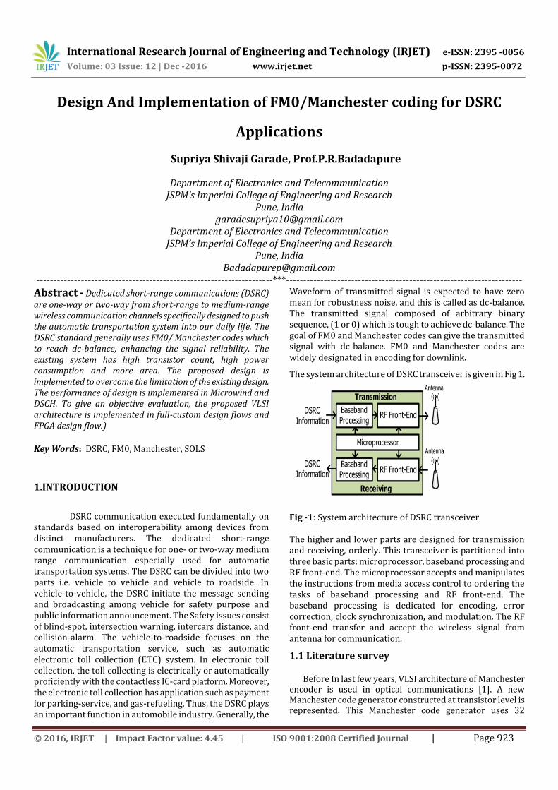
The system architecture of DSRC transceiver is given in Fig 1.
Fig -1: System architecture of DSRC transceiver The higher and lower parts are designed for transmission and receiving, orderly. This transceiver is partitioned into three basic parts: microprocessor, baseband processing and RF front-end. The microprocessor accepts and manipulates the instructions from media access control to ordering the tasks of baseband processing and RF front-end. The baseband processing is dedicated for encoding, error correction, clock synchronization, and modulation. The RF front-end transfer and accept the wireless signal from antenna for communication.
1.1 Literature survey
Before In last few years, VLSI architecture of Manchester encoder is used in optical communications [1]. A new Manchester code generator constructed at transistor level is represented. This Manchester code generator uses 32
International Research Journal of Engineering and Technology (IRJET) e-ISSN: 2395 -0056
Volume: 03 Issue: 12 | Dec -2016 www.irjet.net p-ISSN: 2395-0072
© 2016, IRJET | Impact Factor value: 4.45 | ISO 9001:2008 Certified Journal | Page 924
transistors and it has same complexity as a standard Dflip-flop.
The VLSI architecture of Manchester encoder [2] further changes the architecture of switch in [1] by the NMOS device. It is realized in 90-nm CMOS technology, and it has maximum clock frequency as high as 5 GHz. The high-speed VLSI architecture also fully reused with Miller and Manchester encodings [3] for radio frequency identification (RFID) applications is implemented. This design is realized in 0.35-μm CMOS technology. It has the maximum operation frequency is 200 MHz.This design uses concept of parallel operation to improve data throughput. In additionally, the technique of hardware sharing is improved in design to reduce the number of transistors. The design uses TSMC CMOS 0.35-μm 2P4M technology.
A Manchester encoding architecture for ultrahigh frequency (UHF) RFID tag emulator [4] is further designed. This hardware architecture is constructed from the finite state machine of Manchester code, and is implemented into field-programmable gate array (FPGA) prototyping system. The similar methodology is further applied to individually design FM0 and Miller encoders also for UHF RFID Tag emulator [5].It has maximum operating frequency is about 192 MHz. Furthermore, [6] combines frequency shift keying (FSK) modulation and demodulation withManchester codec in hardware realization. The fully reused VLSI architecture of FM0 and Manchester encoding using SOLS technique [7] is designed in 0.18-µm 1P6M CMOS technology. The maximum operation frequency is 2 GHz and 900 MHz for Manchester and FM0 encodings, respectively. The power consumption is 1.58 mw at 2 GHz for Manchester encoding and 1.14 mw at 900 MHz for FM0 encoding. To give an objective evaluation, the VLSI design is realized in full-custom design flows and FPGA design flow. This design improves HUR upto 100%.
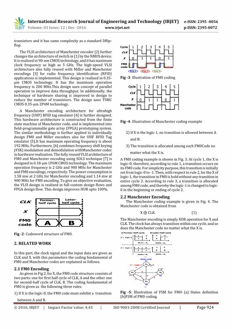
Fig -2: Codeword structure of FM0.
2. RELATED WORK In this part, the clock signal and the input data are given as CLK and X. with this parameters the coding fundamental of FM0 and Manchester codes are explained as follows.
2.1 FM0 Encoding As given in Fig 2, for X, the FM0 code structure consists of
two parts: one for first half cycle of CLK, A and the other one for second-half cycle of CLK, B. The coding fundamental of FM0 is given as the following three rules.
1) If X is the logic-0, the FM0 code must exhibit a transition
between A and B.
Fig -3: Illustration of FM0 coding
Fig -4: Illustration of Manchester coding example
2) If X is the logic-1, no transition is allowed between A
and B.
3) The transition is allocated among each FM0Code no
matter what the X is.
A FM0 coding example is shown in Fig. 3. At cycle 1, the X is logic-0; therefore, according to rule 1, a transition occurs on its FM0 code. For simplicity purpose, this transition is initially set from logic-0 to -1. Then, with respect to rule 2, for the X of logic-1, the transition in FM0 is hold without any transition in entire cycle 2. According to rule 3, a transition is allocated among FM0 code, and thereby the logic-1 is changed to logic-0 in the beginning or ending of cycle 2.
2.2 Manchester Encoding The Manchester coding example is given in Fig. 4. The
Manchester code is obtained from
X ⊕ CLK. (1)
The Manchester encoding is simply XOR operation for X and CLK. The clock has always transition within one cycle, and so does the Manchester code no matter what the X is.
Fig -5: Illustration of FSM for FMO (a) States definition (b)FSM of FM0 coding.
International Research Journal of Engineering and Technology (IRJET) e-ISSN: 2395 -0056
Volume: 03 Issue: 12 | Dec -2016 www.irjet.net p-ISSN: 2395-0072
© 2016, IRJET | Impact Factor value: 4.45 | ISO 9001:2008 Certified Journal | Page 925
3.HARDWARE ARCHITECTURE OF FM0/MANCHESTER ENCODERS WITHOUT SOLS TECHNIQUE
The hardware architecture of Manchester coding is as
simple as a XOR operation. However, the construction of
hardware architecture for FM0 is not as simple as that of
Manchester encoding. The hardware architecture of FM0
coding is constructed with the help of FSM of FM0. According
to the coding fundamental of FM0, the FSM of FM0 coding is
indicated in Fig. 5(b). Assume the initial state is S1 and its
state code is 11 for A and B, respectively. Suppose S1 is 11,
then if X = logic 0 then next state for S1 is S3 i.e. 01 and X =
logic 1 then next state for S1 is S4 i.e. 00.So, the state-
transition for each state can be totally constructed.
The FSM of FM0 coding can also construct the
transition table of each state, as given in Table II. A(t)and
B(t)denotes the discrete-time state code of current-state at
time instant t. Their previous-states are represent as the
A(t− 1) and the B(t− 1), respectively. With the help of
transition table, the Boolean functions of A (t) and B (t)are
given as follows:
A(t)= (2)
B(t)= X⊕B(t-1) (3)
With both A(t) and B(t), the Boolean function of FM0 code is
represent as
CLK A (t) + B (t) (4)
With (1) and (4), the hardware construction of FM0 and
Manchester encoders are given in Fig.6
Fig -6: Basic Hardware construction of FM0 and Manchester
encodings Without SOLS Technique
4.FM0/MANCHESTER CODER USING SOLS TECHNIQUE The Goal of SOLS technique is to construct a fully reused
VLSI architecture for FM0/Manchester encodings as shown
in fig.7. The SOLS technique is divided into two parts: area-
Fig -7: VLSI architecture of FM0 and Manchester
encodings using SOLS technique.
compact retiming and balance logic-operation sharing. The
area-compact retiming relocates the hardware resource to
reduce transistors. The balance logic-operation sharing
efficiently merges FM0 and Manchester encodings with fully
reused hardware architecture.
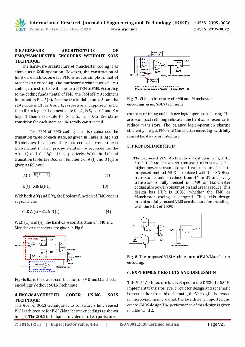
5. PROPOSED METHOD
The proposed VLSI Architecture as shown in fig.8.The SOLS Technique uses 44 transistor ulternatively has higher power consumption and uses more area.hence in proposed method MUX is replaced with the XNOR.so transistor count is reduce from 44 to 31 and every transistor is fully reused in FM0 or Manchester coding.also power consumption and area is reduce, This design has HUR is 100%, whether the FM0 or Manchester coding is adopted. Thus, this design provides a fully reused VLSI architecture for encodings with the HUR of 100%.
Fig -8: The proposed VLSI Architecture of FM0/Manchester
encoding.
6. EXPERIMENT RESULTS AND DISCUSSION This VLSI Architecture is developed in the DSCH. In DSCH,
Implement transistor level circuit for design and schematic
is created then from this schematic, the Verilog file is created
in microwind. In microwind, the foundries is imported and
create CMOS design.The performance of this design is given
in table 1and 2.

International Research Journal of Engineering and Technology (IRJET) e-ISSN: 2395 -0056
Volume: 03 Issue: 12 | Dec -2016 www.irjet.net p-ISSN: 2395-0072
© 2016, IRJET | Impact Factor value: 4.45 | ISO 9001:2008 Certified Journal | Page 926
Table -1: Performance of the VLSI Architecture OF FM0 And Manchester Encodings Using The SOLS Technique Previous Work Previous
work
This work This work
Realization 0.18-μm CMOS Xilinx FPGA
Spartan 2
0.18-μm CMOS Xilinx FPGA
Spartan 2
Supply Voltage 1.8 V 3.3 V 1.8 V 3.3 V
Coding
methods
FM0
Manchester
FM0
Manchester
FM0
Manchester
FM0
Manchester
Operation
frequency
900 MHz
2 GHz
296 MHz 2 GHz 296.033Mhz
Power
consumption
1.14mW
1.58mW
28.30mW
1.415mW
1.285mW
18.24mW
HUR 100% 100% 100% 100%
Area 65.98×30.43
μm2
N/A 77.10 x 24.60
μm2
N/A
Transistor
Count
44 N/A 31 N/A
FPGA resource
usage
N/A Slice:1
Flip-Flop:1
LUTs:1
Bonded
IOBs:5
N/A Slice:1
Flip-Flop:1
LUTs:4
Bonded IOBs:5
Table-2: Performance Evaluation of the proposed Technique
Coding Active components (Transistor
count)/Total
components(Transistor count)
HUR
FM0 6(31) /6(31) 100%
Manchester 6(31) /6(31) 100%
Average 6(31) /6(31) 100%
Fig -9: Schematic of proposed design In DSCH.
Fig -10: Simulation of Proposed design in DSCH for FM0
mode
Fig-11: Simulation of Proposed design in DSCH for
Manchester mode
Fig-12: Layout of Proposed Design in Microwind with
Measurement of area
International Research Journal of Engineering and Technology (IRJET) e-ISSN: 2395 -0056
Volume: 03 Issue: 12 | Dec -2016 www.irjet.net p-ISSN: 2395-0072
© 2016, IRJET | Impact Factor value: 4.45 | ISO 9001:2008 Certified Journal | Page 927
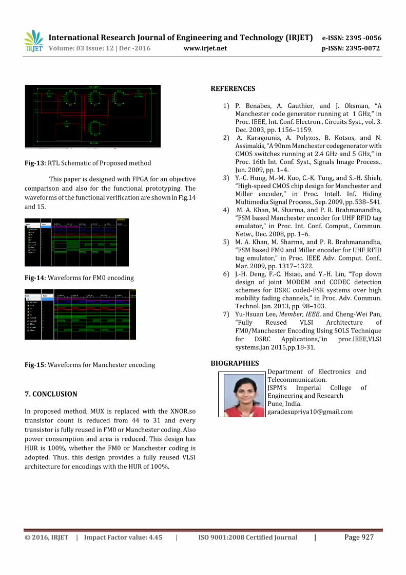
Fig-13: RTL Schematic of Proposed method
This paper is designed with FPGA for an objective
comparison and also for the functional prototyping. The
waveforms of the functional verification are shown in Fig.14
and 15.
Fig-14: Waveforms for FM0 encoding
Fig-15: Waveforms for Manchester encoding
7. CONCLUSION In proposed method, MUX is replaced with the XNOR.so
transistor count is reduced from 44 to 31 and every
transistor is fully reused in FM0 or Manchester coding. Also
power consumption and area is reduced. This design has
HUR is 100%, whether the FM0 or Manchester coding is
adopted. Thus, this design provides a fully reused VLSI
architecture for encodings with the HUR of 100%.
REFERENCES
1) P. Benabes, A. Gauthier, and J. Oksman, “A Manchester code generator running at 1 GHz,” in Proc. IEEE, Int. Conf. Electron., Circuits Syst., vol. 3. Dec. 2003, pp. 1156–1159.
2) A. Karagounis, A. Polyzos, B. Kotsos, and N. Assimakis, “A 90nm Manchester codegenerator with CMOS switches running at 2.4 GHz and 5 GHz,” in Proc. 16th Int. Conf. Syst., Signals Image Process., Jun. 2009, pp. 1–4.
3) Y.-C. Hung, M.-M. Kuo, C.-K. Tung, and S.-H. Shieh, “High-speed CMOS chip design for Manchester and Miller encoder,” in Proc. Intell. Inf. Hiding Multimedia Signal Process., Sep. 2009, pp. 538–541.
4) M. A. Khan, M. Sharma, and P. R. Brahmanandha, “FSM based Manchester encoder for UHF RFID tag emulator,” in Proc. Int. Conf. Comput., Commun. Netw., Dec. 2008, pp. 1–6.
5) M. A. Khan, M. Sharma, and P. R. Brahmanandha, “FSM based FM0 and Miller encoder for UHF RFID tag emulator,” in Proc. IEEE Adv. Comput. Conf., Mar. 2009, pp. 1317–1322.
6) J.-H. Deng, F.-C. Hsiao, and Y.-H. Lin, “Top down design of joint MODEM and CODEC detection schemes for DSRC coded-FSK systems over high mobility fading channels,” in Proc. Adv. Commun. Technol. Jan. 2013, pp. 98–103.
7) Yu-Hsuan Lee, Member, IEEE, and Cheng-Wei Pan, “Fully Reused VLSI Architecture of FM0/Manchester Encoding Using SOLS Technique for DSRC Applications,”in proc.IEEE,VLSI systems.Jan 2015,pp.18-31.
BIOGRAPHIES Department of Electronics and
Telecommunication. JSPM’s Imperial College of Engineering and Research Pune, India. [email protected]
Recommended