International Research Journal of Engineering and Technology (IRJET) e-ISSN: 2395-0056
Volume: 05 Issue: 05 | May-2018 www.irjet.net p-ISSN: 2395-0072
© 2018, IRJET | Impact Factor value: 6.171 | ISO 9001:2008 Certified Journal | Page 319
DESIGN OF A WIDEBAND RECTANGULAR CORRUGATED WAVEGUIDE HORN ANTENNA WITH VARIED SLOT PATTERN
Mridula Naryal1
1M.Tech student, Dept. of electronics and communication engineering, Bahra University Shimla Hills, INDIA ---------------------------------------------------------------------***---------------------------------------------------------------------
Abstract -This paper represents the design of rectangular corrugated horn antenna with varied slot pattern. As we know now’s a day demand of wireless communication increased day by day as the demand increases the improvement in the antenna wide band capabilities also increases. The wide band capabilities increase by various parameters such as low side band, less crosspolarisation, low return losses, less VSWR. The corrugated horn antenna is one of the antennas which proved the less crosspolarisation, low side lobes and good radiation performance. Designing of this antenna carried out using the software CST. The corrugated horn antenna supported the hybrid modes as well as feed for the reflector antennas. The theoretical parameters are related to the mode conversion in which mode is converted to mode by cylindrical corrugated horn with varied slot depth. In this paper the design of antenna in x-ku band with operated in central frequency15.83GHz. The mostly designer considered the conical corrugated horn antenna because its radius is constant and simple to design the main objective of this paper is to design the wideband rectangular corrugated rectangular horn antenna with varied slot pattern shows successful simulation results for less crosspolarisation, less return losses, good VSWR pattern at central frequency15.83GHz also have the mode conversion which contain with mode-matching and varied– slot pattern mode converter due to which antenna operated in wide band frequency in ku band at central operating frequency 15.83GHz used for satellite T.V, Police Radar.
Key Words: C.S.T (computer simulation technology), central operating frequency, corrugated rectangular antenna, varied slot pattern, return loss, VSWR, wide band.
1. INTRODUCTION Horn antenna is very popular at UHF (300-3GHz) and high frequencies such as microwave transmissions. First horn antenna introduce by Indian radio researcher Jagadish Chandra Bose in 1858-1937. The horn antenna is one of the simplest antennas to design it is just long hollow pipe which flared out at its output. It is widely used for space applications but it has some disadvantages such as its dimension become wider for high frequency and narrow band [1].These disadvantages are remove by introduce the wall inside the antenna know as corrugated antenna. The first corrugated horn antenna considered by kay, Simons and kay, Minnett and Thomas [2].
1.1 Principle of Corrugated Antenna
Corrugated means bend folds, alternates and ridges. To shaped into series of parallel ridges and groves so as to add the strength. Corrugated horns become the preferred choice of feed antenna for use in high restrictive applications. This is because of their superior radiation performance and their high copolar pattern symmetry and low crosspolarisation. The principle of operation of corrugated horn antenna can be explained by influence of the corrugated wall and how they affect the distribution of the electromagnetic field on the inside of the wall.
The corrugated antenna have mainly three advantages
low cross polarization, less side lobes and good radiation pattern these parameters make corrugated antenna used for wide band frequency. The corrugated horn antenna support hybrid modes are basically combination of TE and TM modes. For this combination to propagate as a single entity with a common propagating velocity, the horn or waveguide must have anisotropic surface –reactance properties: properties that satisfied by the corrugated surface [3]. The wide –band horn antenna which having the larger aperture has better crosspolarisation performance at the band edges than the narrow-band horn [4].
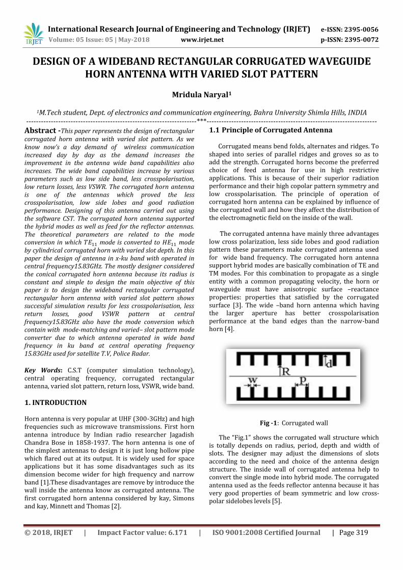
Fig -1: Corrugated wall
The “Fig.1” shows the corrugated wall structure which is totally depends on radius, period, depth and width of slots. The designer may adjust the dimensions of slots according to the need and choice of the antenna design structure. The inside wall of corrugated antenna help to convert the single mode into hybrid mode. The corrugated antenna used as the feeds reflector antenna because it has very good properties of beam symmetric and low cross-polar sidelobes levels [5].
International Research Journal of Engineering and Technology (IRJET) e-ISSN: 2395-0056
Volume: 05 Issue: 05 | May-2018 www.irjet.net p-ISSN: 2395-0072
© 2018, IRJET | Impact Factor value: 6.171 | ISO 9001:2008 Certified Journal | Page 320
Table -1: Corrugated Horn Parameters
QUANTITY SYMBOL Input radius
Length L Total number of slots N
Number of slots in mode converter
Slot Pitch P= ⁄
Slot Width W Width of the slot
teeth
⁄
The table 1 shows all the important parameters of the corrugated horn antenna.
The method of mode converter with five slots are capable to achieve a better return losses than 30 dB over the band 2.7<ka<3.8 with mode in balanced condition at ka=2.9[6]. In this design our one more purpose to achieve maximum mode conversion. The mode matching provides the input waveguide supporting the mode and a large value matched to the output waveguide which support the mode.
A common method for achieving the mode converter is
to use a corrugated waveguide transition section in which the depth of the slots gradually decreases from an initial value of λ/2 (so that the input slot appears as a short circuit) to a final slot-depth of approximately λ/4 as given by the corrugated output-waveguide.
Table -2: Mode Matching Technique Parameters
Parameters Equations Wavelength =
Pitch P=(0.1) Slot width W=(0.75)P
Width of the Slot teeth T=P-W Initial radius =
The table 2 shows the required mode matching
technique parameters. In the normal corrugated antenna the input mode at the throat region will be provide waveguide mode, this mode defines approximately the input radius of the corrugated horn antenna profile. For minimum return loss of this mode, corrugation depth at throat region must be around /2[7]. The advantage of this antenna is that it has no resonant element can be operate over a wide range of frequencies [8].
2. ANTENNA DESIGN
The antenna design contain varies parameters such as waveguide port , the input radius, length, total number of slots , numbers of slots in mode converters, slot pitch, slot width, slot pitch-to-width ratio, width of slot teeth all these designing parameters are define below:
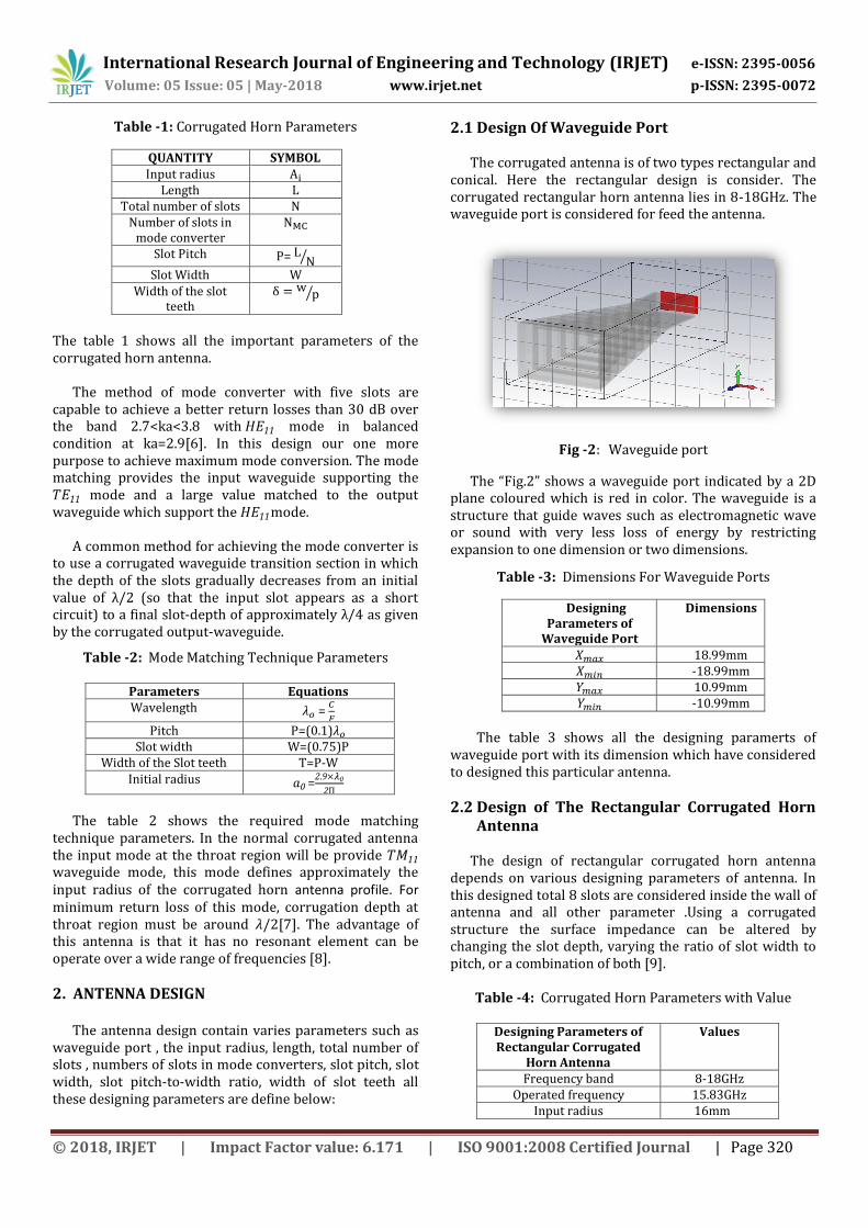
2.1 Design Of Waveguide Port The corrugated antenna is of two types rectangular and
conical. Here the rectangular design is consider. The corrugated rectangular horn antenna lies in 8-18GHz. The waveguide port is considered for feed the antenna.
Fig -2: Waveguide port
The “Fig.2” shows a waveguide port indicated by a 2D plane coloured which is red in color. The waveguide is a structure that guide waves such as electromagnetic wave or sound with very less loss of energy by restricting expansion to one dimension or two dimensions.
Table -3: Dimensions For Waveguide Ports
Designing Parameters of
Waveguide Port
Dimensions
18.99mm -18.99mm 10.99mm -10.99mm
The table 3 shows all the designing paramerts of
waveguide port with its dimension which have considered to designed this particular antenna.
2.2 Design of The Rectangular Corrugated Horn Antenna
The design of rectangular corrugated horn antenna
depends on various designing parameters of antenna. In this designed total 8 slots are considered inside the wall of antenna and all other parameter .Using a corrugated structure the surface impedance can be altered by changing the slot depth, varying the ratio of slot width to pitch, or a combination of both [9].
Table -4: Corrugated Horn Parameters with Value
Designing Parameters of Rectangular Corrugated
Horn Antenna
Values
Frequency band 8-18GHz Operated frequency 15.83GHz
Input radius 16mm
International Research Journal of Engineering and Technology (IRJET) e-ISSN: 2395-0056
Volume: 05 Issue: 05 | May-2018 www.irjet.net p-ISSN: 2395-0072
© 2018, IRJET | Impact Factor value: 6.171 | ISO 9001:2008 Certified Journal | Page 321
Length 120mm Total numbers of slots 8
Total numbers of slots in mode converter
8
Slot pitch 15mm Slot width 5mm
Slot pitch-to-width ratio 0.33mm Width of the slot teeth 10.05mm
The table 4 shows the no. of designing parameter considered for the design of 8 slot pattern with its value.
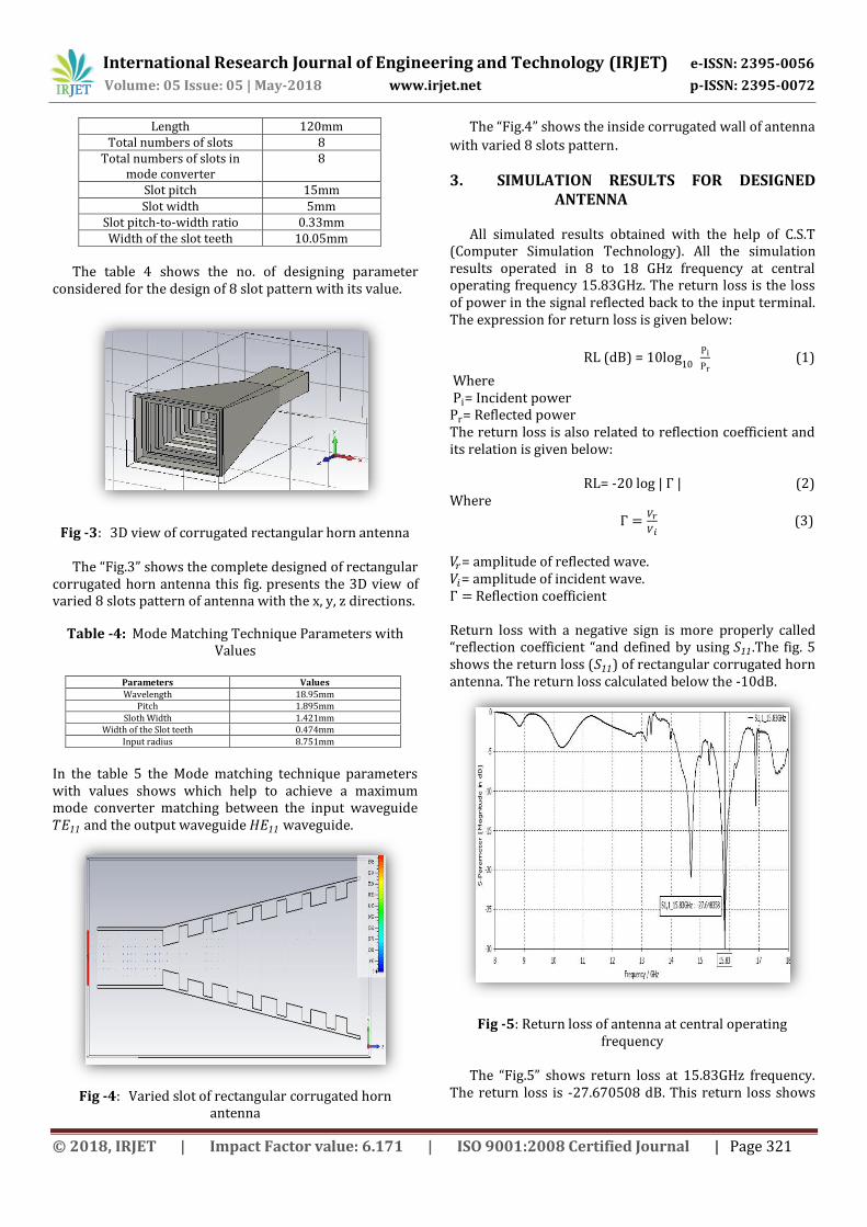
Fig -3: 3D view of corrugated rectangular horn antenna
The “Fig.3” shows the complete designed of rectangular corrugated horn antenna this fig. presents the 3D view of varied 8 slots pattern of antenna with the x, y, z directions.
Table -4: Mode Matching Technique Parameters with Values
Parameters Values Wavelength 18.95mm
Pitch 1.895mm Sloth Width 1.421mm
Width of the Slot teeth 0.474mm Input radius 8.751mm
In the table 5 the Mode matching technique parameters with values shows which help to achieve a maximum mode converter matching between the input waveguide and the output waveguide waveguide.
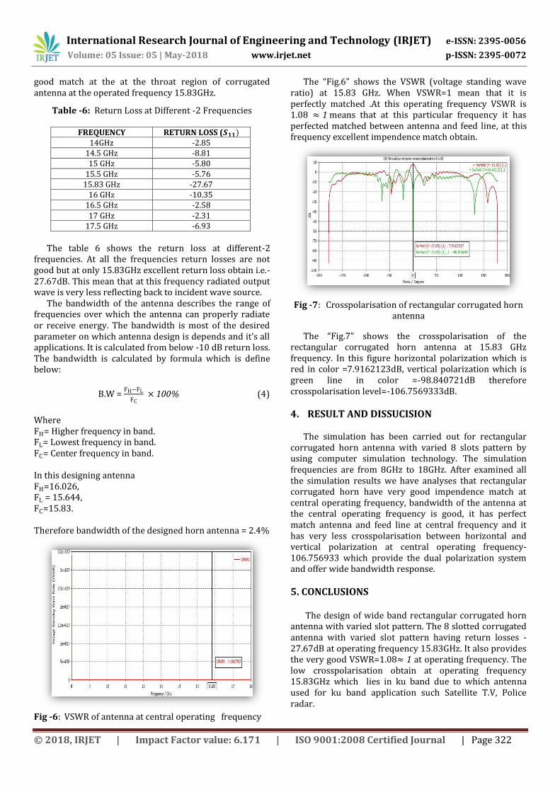
Fig -4: Varied slot of rectangular corrugated horn
antenna
The “Fig.4” shows the inside corrugated wall of antenna
with varied 8 slots pattern.
3. SIMULATION RESULTS FOR DESIGNED ANTENNA
All simulated results obtained with the help of C.S.T
(Computer Simulation Technology). All the simulation results operated in 8 to 18 GHz frequency at central operating frequency 15.83GHz. The return loss is the loss of power in the signal reflected back to the input terminal. The expression for return loss is given below:
RL (dB) = 10log1
Pi
Pr (1)
Where Pi= Incident power Pr= Reflected power The return loss is also related to reflection coefficient and its relation is given below:
RL= -20 log | | (2) Where
(3)
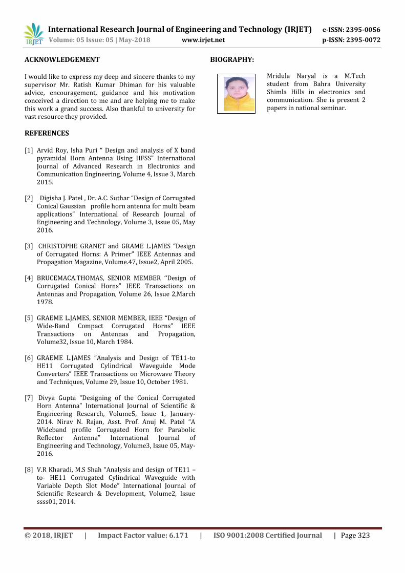
= amplitude of reflected wave. = amplitude of incident wave. Reflection coefficient Return loss with a negative sign is more properly called “reflection coefficient “and defined by using .The fig. 5 shows the return loss ( ) of rectangular corrugated horn antenna. The return loss calculated below the -10dB.
Fig -5: Return loss of antenna at central operating frequency
The “Fig.5” shows return loss at 15.83GHz frequency.
The return loss is -27.670508 dB. This return loss shows
International Research Journal of Engineering and Technology (IRJET) e-ISSN: 2395-0056
Volume: 05 Issue: 05 | May-2018 www.irjet.net p-ISSN: 2395-0072
© 2018, IRJET | Impact Factor value: 6.171 | ISO 9001:2008 Certified Journal | Page 322
good match at the at the throat region of corrugated antenna at the operated frequency 15.83GHz.
Table -6: Return Loss at Different -2 Frequencies
FREQUENCY RETURN LOSS ( 14GHz -2.85
14.5 GHz -8.81 15 GHz -5.80
15.5 GHz -5.76 15.83 GHz -27.67
16 GHz -10.35 16.5 GHz -2.58 17 GHz -2.31
17.5 GHz -6.93
The table 6 shows the return loss at different-2
frequencies. At all the frequencies return losses are not good but at only 15.83GHz excellent return loss obtain i.e.-27.67dB. This mean that at this frequency radiated output wave is very less reflecting back to incident wave source.
The bandwidth of the antenna describes the range of frequencies over which the antenna can properly radiate or receive energy. The bandwidth is most of the desired parameter on which antenna design is depends and it’s all applications. It is calculated from below -10 dB return loss. The bandwidth is calculated by formula which is define below:
B.W = FH FL
FC (4)
Where FH= Higher frequency in band. FL= Lowest frequency in band. FC= Center frequency in band. In this designing antenna FH=16.026, FL = 15.644, FC=15.83. Therefore bandwidth of the designed horn antenna = 2.4%
Fig -6: VSWR of antenna at central operating frequency
The “Fig.6” shows the VSWR (voltage standing wave ratio) at 15.83 GHz. When VSWR=1 mean that it is perfectly matched .At this operating frequency VSWR is 1.08 means that at this particular frequency it has perfected matched between antenna and feed line, at this frequency excellent impendence match obtain.
Fig -7: Crosspolarisation of rectangular corrugated horn
antenna
The “Fig.7” shows the crosspolarisation of the rectangular corrugated horn antenna at 15.83 GHz frequency. In this figure horizontal polarization which is red in color =7.9162123dB, vertical polarization which is green line in color =-98.840721dB therefore crosspolarisation level=-106.7569333dB.
4. RESULT AND DISSUCISION The simulation has been carried out for rectangular
corrugated horn antenna with varied 8 slots pattern by using computer simulation technology. The simulation frequencies are from 8GHz to 18GHz. After examined all the simulation results we have analyses that rectangular corrugated horn have very good impendence match at central operating frequency, bandwidth of the antenna at the central operating frequency is good, it has perfect match antenna and feed line at central frequency and it has very less crosspolarisation between horizontal and vertical polarization at central operating frequency-106.756933 which provide the dual polarization system and offer wide bandwidth response.
5. CONCLUSIONS
The design of wide band rectangular corrugated horn antenna with varied slot pattern. The 8 slotted corrugated antenna with varied slot pattern having return losses -27.67dB at operating frequency 15.83GHz. It also provides the very good VSWR=1.08 at operating frequency. The low crosspolarisation obtain at operating frequency 15.83GHz which lies in ku band due to which antenna used for ku band application such Satellite T.V, Police radar.
International Research Journal of Engineering and Technology (IRJET) e-ISSN: 2395-0056
Volume: 05 Issue: 05 | May-2018 www.irjet.net p-ISSN: 2395-0072
© 2018, IRJET | Impact Factor value: 6.171 | ISO 9001:2008 Certified Journal | Page 323
ACKNOWLEDGEMENT I would like to express my deep and sincere thanks to my supervisor Mr. Ratish Kumar Dhiman for his valuable advice, encouragement, guidance and his motivation conceived a direction to me and are helping me to make this work a grand success. Also thankful to university for vast resource they provided.
REFERENCES [1] Arvid Roy, Isha Puri “ Design and analysis of X band
pyramidal Horn Antenna Using HFSS” International Journal of Advanced Research in Electronics and Communication Engineering, Volume 4, Issue 3, March 2015.
[2] Digisha J. Patel , Dr. A.C. Suthar “Design of Corrugated Conical Gaussian profile horn antenna for multi beam applications” International of Research Journal of Engineering and Technology, Volume 3, Issue 05, May 2016.
[3] CHRISTOPHE GRANET and GRAME L.JAMES “Design
of Corrugated Horns: A Primer” IEEE Antennas and Propagation Magazine, Volume.47, Issue2, April 2005.
[4] BRUCEMACA.THOMAS, SENIOR MEMBER ‘‘Design of
Corrugated Conical Horns” IEEE Transactions on Antennas and Propagation, Volume 26, Issue 2,March 1978.
[5] GRAEME L.JAMES, SENIOR MEMBER, IEEE “Design of
Wide-Band Compact Corrugated Horns” IEEE Transactions on Antennas and Propagation, Volume32, Issue 10, March 1984.
[6] GRAEME L.JAMES “Analysis and Design of TE11-to
HE11 Corrugated Cylindrical Waveguide Mode Converters” IEEE Transactions on Microwave Theory and Techniques, Volume 29, Issue 10, October 1981.
[7] Divya Gupta “Designing of the Conical Corrugated
Horn Antenna” International Journal of Scientific & Engineering Research, Volume5, Issue 1, January-2 14. Nirav N. Rajan, Asst. Prof. Anuj M. Patel “A Wideband profile Corrugated Horn for Parabolic Reflector Antenna” International Journal of Engineering and Technology, Volume3, Issue 05, May-2016.
[8] V.R Kharadi, M.S Shah “Analysis and design of TE11 –to- HE11 Corrugated Cylindrical Waveguide with Variable Depth Slot Mode” International Journal of Scientific Research & Development, Volume2, Issue ssss01, 2014.
BIOGRAPHY:
Mridula Naryal is a M.Tech student from Bahra University Shimla Hills in electronics and communication. She is present 2 papers in national seminar.
1’st Aut
Recommended