Team Electric OwlDesign of an Unmanned Aerial Vehicle for
Martian ExplorationFinal Report
Rice UniversityDepartment of Electrical and Computer Engineering
6100 Main St. MS-366Houston, TX 77005
Anthony Austin Senior, Electrical Engineering [email protected]
Jeffrey Bridge Senior, Electrical Engineering [email protected]
Robert Brockman II Senior, Electrical Engineering [email protected]
Peter Hokanson Senior, Electrical Engineering [email protected]
Faculty Advisor: Dr. Gary Woods, Elec. and Comp. Eng., [email protected] Mentor: David Fuson, ESGC Jacobs, [email protected]
TSGC Mentor: Dr. Hum Mandell, UT Center for Space Research, [email protected]
Spring 2011
Contents
1 Introduction 101.1 Mars: The Next Frontier . . . . . . . . . . . . . . . . . . . . . . . . . . . . . . . 101.2 Unmanned Martian Exploration . . . . . . . . . . . . . . . . . . . . . . . . . . . 111.3 Airborne Mission Requirements . . . . . . . . . . . . . . . . . . . . . . . . . . 11
1.3.1 Flight Environment . . . . . . . . . . . . . . . . . . . . . . . . . . . . . 121.3.2 Extreme Distance . . . . . . . . . . . . . . . . . . . . . . . . . . . . . . 121.3.3 Component Failure . . . . . . . . . . . . . . . . . . . . . . . . . . . . . 13
1.4 The Project . . . . . . . . . . . . . . . . . . . . . . . . . . . . . . . . . . . . . 14
2 Design Strategy 152.1 Fault-Tolerant Mars-Capable Avionics . . . . . . . . . . . . . . . . . . . . . . . 15
2.1.1 Control Surface Actuation . . . . . . . . . . . . . . . . . . . . . . . . . . 152.1.2 Radio Communication . . . . . . . . . . . . . . . . . . . . . . . . . . . . 162.1.3 Flight-State Sensors . . . . . . . . . . . . . . . . . . . . . . . . . . . . . 172.1.4 Flight Computer . . . . . . . . . . . . . . . . . . . . . . . . . . . . . . . 17
2.2 Project Focus . . . . . . . . . . . . . . . . . . . . . . . . . . . . . . . . . . . . 182.2.1 Flight-Capable Hardware . . . . . . . . . . . . . . . . . . . . . . . . . . 192.2.2 Basic Autopilot . . . . . . . . . . . . . . . . . . . . . . . . . . . . . . . . 192.2.3 Sensor Redundancy . . . . . . . . . . . . . . . . . . . . . . . . . . . . . 192.2.4 Potential for Expansion . . . . . . . . . . . . . . . . . . . . . . . . . . . 20
3 Final Design 213.1 Electrical Hardware . . . . . . . . . . . . . . . . . . . . . . . . . . . . . . . . . 21
3.1.1 Backplane . . . . . . . . . . . . . . . . . . . . . . . . . . . . . . . . . . 223.1.2 Servo Board . . . . . . . . . . . . . . . . . . . . . . . . . . . . . . . . . 243.1.3 Radio Board . . . . . . . . . . . . . . . . . . . . . . . . . . . . . . . . . 253.1.4 Sensors Board . . . . . . . . . . . . . . . . . . . . . . . . . . . . . . . . 263.1.5 General-Purpose Computer (GPC) Board . . . . . . . . . . . . . . . . . 29
3.2 Avionics Firmware . . . . . . . . . . . . . . . . . . . . . . . . . . . . . . . . . . 313.2.1 General Architecture . . . . . . . . . . . . . . . . . . . . . . . . . . . . 323.2.2 Bus Firmware . . . . . . . . . . . . . . . . . . . . . . . . . . . . . . . . 323.2.3 Servo Board . . . . . . . . . . . . . . . . . . . . . . . . . . . . . . . . . 343.2.4 Radio Board . . . . . . . . . . . . . . . . . . . . . . . . . . . . . . . . . 373.2.5 Sensors Board . . . . . . . . . . . . . . . . . . . . . . . . . . . . . . . . 393.2.6 GPC Board (AVR) . . . . . . . . . . . . . . . . . . . . . . . . . . . . . . 423.2.7 GPC Board (ARM) . . . . . . . . . . . . . . . . . . . . . . . . . . . . . . 43
3.2.7.1 System Master . . . . . . . . . . . . . . . . . . . . . . . . . . 433.2.7.2 Custom Real-Time Kernel . . . . . . . . . . . . . . . . . . . . 443.2.7.3 Autopilot Task . . . . . . . . . . . . . . . . . . . . . . . . . . . 46
3.3 Autopilot Software . . . . . . . . . . . . . . . . . . . . . . . . . . . . . . . . . . 473.3.1 General Structure . . . . . . . . . . . . . . . . . . . . . . . . . . . . . . 47
Electric Owl: Final Report 2

CONTENTS
3.3.2 Sensor Redundancy Management . . . . . . . . . . . . . . . . . . . . . 493.3.3 Flight Plan Format . . . . . . . . . . . . . . . . . . . . . . . . . . . . . . 50
3.4 "Houston" Ground Software . . . . . . . . . . . . . . . . . . . . . . . . . . . . . 523.4.1 General Interface . . . . . . . . . . . . . . . . . . . . . . . . . . . . . . 533.4.2 Raster Data . . . . . . . . . . . . . . . . . . . . . . . . . . . . . . . . . 543.4.3 Vector Data . . . . . . . . . . . . . . . . . . . . . . . . . . . . . . . . . 553.4.4 UAV Support . . . . . . . . . . . . . . . . . . . . . . . . . . . . . . . . . 563.4.5 Logging Format . . . . . . . . . . . . . . . . . . . . . . . . . . . . . . . 57
3.5 Communications Protocols . . . . . . . . . . . . . . . . . . . . . . . . . . . . . 583.5.1 Bus Protocol . . . . . . . . . . . . . . . . . . . . . . . . . . . . . . . . . 583.5.2 Radio Downlink Protocol . . . . . . . . . . . . . . . . . . . . . . . . . . 663.5.3 Radio Uplink Protocol . . . . . . . . . . . . . . . . . . . . . . . . . . . . 71
3.6 Prototype Aircraft Hardware . . . . . . . . . . . . . . . . . . . . . . . . . . . . 743.6.1 Airframe . . . . . . . . . . . . . . . . . . . . . . . . . . . . . . . . . . . 743.6.2 Power System . . . . . . . . . . . . . . . . . . . . . . . . . . . . . . . . 763.6.3 Actuators . . . . . . . . . . . . . . . . . . . . . . . . . . . . . . . . . . . 783.6.4 Avionics Mounting . . . . . . . . . . . . . . . . . . . . . . . . . . . . . . 783.6.5 Non-Integrated Sensors . . . . . . . . . . . . . . . . . . . . . . . . . . . 79
3.7 Future Expansion . . . . . . . . . . . . . . . . . . . . . . . . . . . . . . . . . . 793.8 Errata and Revision History . . . . . . . . . . . . . . . . . . . . . . . . . . . . . 81
3.8.1 Hardware Revision I . . . . . . . . . . . . . . . . . . . . . . . . . . . . . 813.8.2 Hardware Revision II . . . . . . . . . . . . . . . . . . . . . . . . . . . . 823.8.3 Hardware Revision III . . . . . . . . . . . . . . . . . . . . . . . . . . . . 84
4 Testing and Results 854.1 Basic Functionality Testing . . . . . . . . . . . . . . . . . . . . . . . . . . . . . 85
4.1.1 Electrical Testing . . . . . . . . . . . . . . . . . . . . . . . . . . . . . . 854.1.2 Software Testing . . . . . . . . . . . . . . . . . . . . . . . . . . . . . . . 854.1.3 Sensor Redundancy Testing . . . . . . . . . . . . . . . . . . . . . . . . 86
4.2 Sensors Calibration . . . . . . . . . . . . . . . . . . . . . . . . . . . . . . . . . 864.3 Hardware-in-the-Loop (HITL) Simulation . . . . . . . . . . . . . . . . . . . . . . 894.4 Flight Tests . . . . . . . . . . . . . . . . . . . . . . . . . . . . . . . . . . . . . 90
4.4.1 Servo Board Flight Test: 08/22/2010 . . . . . . . . . . . . . . . . . . . . 904.4.2 Three-Board Flight Test: 01/07/2011 . . . . . . . . . . . . . . . . . . . . 914.4.3 Initial Autopilot Flight Test: 03/06/2011 . . . . . . . . . . . . . . . . . . . 924.4.4 Basic Autopilot Flight Test: 03/19/2011 . . . . . . . . . . . . . . . . . . . 934.4.5 Redundant Sensors Flight Test I: 03/27/11 . . . . . . . . . . . . . . . . . 944.4.6 Redundant Sensors Flight Test II: 04/02/2011 . . . . . . . . . . . . . . . 94
5 Summary and Recommendations 985.1 Summary . . . . . . . . . . . . . . . . . . . . . . . . . . . . . . . . . . . . . . 985.2 Recommendations and Future Work . . . . . . . . . . . . . . . . . . . . . . . . 99
Electric Owl: Final Report 3

CONTENTS
6 Acknowledgements 1016.1 Technical Advisors . . . . . . . . . . . . . . . . . . . . . . . . . . . . . . . . . 1016.2 Flight Testing . . . . . . . . . . . . . . . . . . . . . . . . . . . . . . . . . . . . 1026.3 Funding Sources . . . . . . . . . . . . . . . . . . . . . . . . . . . . . . . . . . 102
7 References 103
A User’s and Safety Manual 107A.1 Flight Test Procedures . . . . . . . . . . . . . . . . . . . . . . . . . . . . . . . 107
A.1.1 The Day Before . . . . . . . . . . . . . . . . . . . . . . . . . . . . . . . 107A.1.2 Packing Checklist . . . . . . . . . . . . . . . . . . . . . . . . . . . . . . 108A.1.3 At the Field . . . . . . . . . . . . . . . . . . . . . . . . . . . . . . . . . . 110
A.2 Software Dependencies . . . . . . . . . . . . . . . . . . . . . . . . . . . . . . . 113A.3 Programming the Circuit Boards . . . . . . . . . . . . . . . . . . . . . . . . . . 115
A.3.1 AVR Microcontrollers . . . . . . . . . . . . . . . . . . . . . . . . . . . . 115A.3.2 GPC ARM Microcontroller . . . . . . . . . . . . . . . . . . . . . . . . . 117
A.4 Assigning Board IDs . . . . . . . . . . . . . . . . . . . . . . . . . . . . . . . . . 119A.5 Hardware-in-the-Loop Testing . . . . . . . . . . . . . . . . . . . . . . . . . . . 121A.6 Software Utilities . . . . . . . . . . . . . . . . . . . . . . . . . . . . . . . . . . . 124A.7 Sensor Calibration Procedure . . . . . . . . . . . . . . . . . . . . . . . . . . . 125
A.7.1 Step 1: Data Collection . . . . . . . . . . . . . . . . . . . . . . . . . . . 126A.7.1.1 Accelerometers . . . . . . . . . . . . . . . . . . . . . . . . . . 126A.7.1.2 Magnetometers . . . . . . . . . . . . . . . . . . . . . . . . . . 130A.7.1.3 Gyroscopes . . . . . . . . . . . . . . . . . . . . . . . . . . . . 132A.7.1.4 Differential Pressure Sensor . . . . . . . . . . . . . . . . . . . 137
A.7.2 Step 2: Pre-Processing . . . . . . . . . . . . . . . . . . . . . . . . . . . 139A.7.2.1 Accelerometer, Magnetometer, and Differential Pressure Data . 139A.7.2.2 Gyroscope Data . . . . . . . . . . . . . . . . . . . . . . . . . . 140
A.7.3 Step 3: Model Fitting and Analysis . . . . . . . . . . . . . . . . . . . . . 141A.7.4 Step 4: Storing Values in EEPROM . . . . . . . . . . . . . . . . . . . . 144
A.8 Compiling the ARM Development Toolchain . . . . . . . . . . . . . . . . . . . . 146A.9 Compiling Open OCD . . . . . . . . . . . . . . . . . . . . . . . . . . . . . . . . 150A.10 Safety Precautions . . . . . . . . . . . . . . . . . . . . . . . . . . . . . . . . . 151
A.10.1 Lithium-Polymer Batteries . . . . . . . . . . . . . . . . . . . . . . . . . . 151A.10.2 R/C Flying . . . . . . . . . . . . . . . . . . . . . . . . . . . . . . . . . . 151A.10.3 Construction . . . . . . . . . . . . . . . . . . . . . . . . . . . . . . . . . 152
A.11 Legal Requirements . . . . . . . . . . . . . . . . . . . . . . . . . . . . . . . . . 152A.11.1 FCC Radio Frequency Regulations . . . . . . . . . . . . . . . . . . . . . 152A.11.2 FAA Flight Regulations . . . . . . . . . . . . . . . . . . . . . . . . . . . 152
B Schematics and CAD Drawings 153
Electric Owl: Final Report 4

CONTENTS
C Assembly Instructions and Bill of Materials 188C.1 Aircraft Hardware . . . . . . . . . . . . . . . . . . . . . . . . . . . . . . . . . . 188C.2 Avionics Package . . . . . . . . . . . . . . . . . . . . . . . . . . . . . . . . . . 189
C.2.1 Backplane, revision 03 . . . . . . . . . . . . . . . . . . . . . . . . . . . 193C.2.2 Servo Board, revision 03 . . . . . . . . . . . . . . . . . . . . . . . . . . 193C.2.3 Radio Board, revision 03 . . . . . . . . . . . . . . . . . . . . . . . . . . 198C.2.4 Sensors Board, revision 03 . . . . . . . . . . . . . . . . . . . . . . . . . 200C.2.5 GPC Board, revision 02 . . . . . . . . . . . . . . . . . . . . . . . . . . . 204
C.3 Additional Tools . . . . . . . . . . . . . . . . . . . . . . . . . . . . . . . . . . . 208C.3.1 Airframe Construction . . . . . . . . . . . . . . . . . . . . . . . . . . . . 208C.3.2 Software Development . . . . . . . . . . . . . . . . . . . . . . . . . . . 209C.3.3 Testing Supplies . . . . . . . . . . . . . . . . . . . . . . . . . . . . . . . 209
D Budget 210D.1 Revenue . . . . . . . . . . . . . . . . . . . . . . . . . . . . . . . . . . . . . . . 210D.2 Expenses . . . . . . . . . . . . . . . . . . . . . . . . . . . . . . . . . . . . . . 210
Electric Owl: Final Report 5

List of Figures
2.1 System block diagram of some of the features that might be needed for a Mars-capable system. . . . . . . . . . . . . . . . . . . . . . . . . . . . . . . . . . . . 16
3.1 Photograph showing all four types of boards plugged into the backplane. . . . . 213.2 Data flow in the autopilot . . . . . . . . . . . . . . . . . . . . . . . . . . . . . . 473.3 Byte structure of a bus packet. . . . . . . . . . . . . . . . . . . . . . . . . . . . 593.4 Byte structure of a downlink packet. . . . . . . . . . . . . . . . . . . . . . . . . 673.5 Byte structure of an uplink packet. . . . . . . . . . . . . . . . . . . . . . . . . . 72
4.1 Heading-lock telemetry from second flight on 04/02/2011. The blue line indi-cates the plane’s actual heading. The gray regions indicate parts of the flight forwhich the autopilot was active, and the orange lines indicate the plane’s desiredheading during those times. . . . . . . . . . . . . . . . . . . . . . . . . . . . . . 95
4.2 Plot of plane’s trajectory during the second flight test on 04/02/2011. The redlines indicate parts during which the autopilot was active. Arrows on the linesegment indicate the plane’s direction of travel. . . . . . . . . . . . . . . . . . . 97
B.1 Backplane revision 03 circuit schematic (1/4) . . . . . . . . . . . . . . . . . . . 154B.2 Backplane revision 03 circuit schematic (2/4) . . . . . . . . . . . . . . . . . . . 155B.3 Backplane revision 03 circuit schematic (3/4) . . . . . . . . . . . . . . . . . . . 156B.4 Backplane revision 03 circuit schematic (4/4) . . . . . . . . . . . . . . . . . . . 157B.5 Servo board revision 03 circuit schematic (1/8) . . . . . . . . . . . . . . . . . . 158B.6 Servo board revision 03 circuit schematic (2/8) . . . . . . . . . . . . . . . . . . 159B.7 Servo board revision 03 circuit schematic (3/8) . . . . . . . . . . . . . . . . . . 160B.8 Servo board revision 03 circuit schematic (4/8) . . . . . . . . . . . . . . . . . . 161B.9 Servo board revision 03 circuit schematic (5/8) . . . . . . . . . . . . . . . . . . 162B.10 Servo board revision 03 circuit schematic (6/8) . . . . . . . . . . . . . . . . . . 163B.11 Servo board revision 03 circuit schematic (7/8) . . . . . . . . . . . . . . . . . . 164B.12 Servo board revision 03 circuit schematic (8/8) . . . . . . . . . . . . . . . . . . 165B.13 Radio board revision 03 circuit schematic (1/5) . . . . . . . . . . . . . . . . . . 166B.14 Radio board revision 03 circuit schematic (2/5) . . . . . . . . . . . . . . . . . . 167B.15 Radio board revision 03 circuit schematic (3/5) . . . . . . . . . . . . . . . . . . 168B.16 Radio board revision 03 circuit schematic (4/5) . . . . . . . . . . . . . . . . . . 169B.17 Radio board revision 03 circuit schematic (5/5) . . . . . . . . . . . . . . . . . . 170B.18 Sensors board revision 03 circuit schematic (1/8) . . . . . . . . . . . . . . . . . 171B.19 Sensors board revision 03 circuit schematic (2/8) . . . . . . . . . . . . . . . . . 172B.20 Sensors board revision 03 circuit schematic (3/8) . . . . . . . . . . . . . . . . . 173B.21 Sensors board revision 03 circuit schematic (4/8) . . . . . . . . . . . . . . . . . 174B.22 Sensors board revision 03 circuit schematic (5/8) . . . . . . . . . . . . . . . . . 175B.23 Sensors board revision 03 circuit schematic (6/8) . . . . . . . . . . . . . . . . . 176B.24 Sensors board revision 03 circuit schematic (7/8) . . . . . . . . . . . . . . . . . 177
Electric Owl: Final Report 6

LIST OF FIGURES
B.25 Sensors board revision 03 circuit schematic (8/8) . . . . . . . . . . . . . . . . . 178B.26 GPC board revision 02 circuit schematic (1/9) . . . . . . . . . . . . . . . . . . . 179B.27 GPC board revision 02 circuit schematic (2/9) . . . . . . . . . . . . . . . . . . . 180B.28 GPC board revision 02 circuit schematic (3/9) . . . . . . . . . . . . . . . . . . . 181B.29 GPC board revision 02 circuit schematic (4/9) . . . . . . . . . . . . . . . . . . . 182B.30 GPC board revision 02 circuit schematic (5/9) . . . . . . . . . . . . . . . . . . . 183B.31 GPC board revision 02 circuit schematic (6/9) . . . . . . . . . . . . . . . . . . . 184B.32 GPC board revision 02 circuit schematic (7/9) . . . . . . . . . . . . . . . . . . . 185B.33 GPC board revision 02 circuit schematic (8/9) . . . . . . . . . . . . . . . . . . . 186B.34 GPC board revision 02 circuit schematic (9/9) . . . . . . . . . . . . . . . . . . . 187
C.1 Front assembly diagram for Backplane Rev 03 . . . . . . . . . . . . . . . . . . 190C.2 Front assembly diagram for Servo Board Rev 03 . . . . . . . . . . . . . . . . . 191C.3 Front assembly diagram for Radio Board Rev 03 . . . . . . . . . . . . . . . . . 191C.4 Front assembly diagram for Sensors Board Rev 03 . . . . . . . . . . . . . . . . 192C.5 Front assembly diagram for GPC Board Rev 02 . . . . . . . . . . . . . . . . . . 192
Electric Owl: Final Report 7

List of Tables
3.1 Microcontroller ADC pin assignments on Sensors Board, Rev 03. . . . . . . . . 283.2 Special bytes and escape sequences. . . . . . . . . . . . . . . . . . . . . . . . 593.3 Bus command types and corresponding identification bytes. . . . . . . . . . . . 613.4 Data register codes used with BCMD_TELEM_FETCH and BCMD_TELEM_REPLY pack-
ets. . . . . . . . . . . . . . . . . . . . . . . . . . . . . . . . . . . . . . . . . . . 623.5 Layout of the data field for BCMD_SENSORS_REPLAY_HIRATE packets. Note that
the sensor values are stored in little-endian order. . . . . . . . . . . . . . . . . . 643.6 Layout of the data field for BCMD_SENSORS_REPLAY_LORATE packets. Taken from
the Garmin Device Interface Specification [1]. . . . . . . . . . . . . . . . . . . . 653.7 Layout of the data field for BCMD_SERVO_SETSERVOS packets. Note that the val-
ues must be sent in little-endian order. . . . . . . . . . . . . . . . . . . . . . . . 653.8 Layout of the data field for BCMD_SENSORS_REPLY_AHPRS packets. . . . . . . . . 663.9 Downlink packet types and corresponding identification bytes. . . . . . . . . . . 673.10 Telemetry channel types and corresponding marker bytes. . . . . . . . . . . . . 683.10 Telemetry channel types and corresponding marker bytes. . . . . . . . . . . . . 693.10 Telemetry channel types and corresponding marker bytes. . . . . . . . . . . . . 703.11 Downlink packet types and corresponding identification bytes. . . . . . . . . . . 733.12 Layout of the data field for UL_CMD_JOYSTICK packets. . . . . . . . . . . . . . . 74
A.1 Software dependencies required for Electric Owl development. . . . . . . . . . 114
C.1 Bill of Materials for Test Airframe . . . . . . . . . . . . . . . . . . . . . . . . . . 188C.2 Bill of Materials for Backplane Rev 03 . . . . . . . . . . . . . . . . . . . . . . . 193C.3 Bill of Materials for Servo Board Rev 03 . . . . . . . . . . . . . . . . . . . . . . 193C.3 Bill of Materials for Servo Board Rev 03 . . . . . . . . . . . . . . . . . . . . . . 194C.3 Bill of Materials for Servo Board Rev 03 . . . . . . . . . . . . . . . . . . . . . . 195C.3 Bill of Materials for Servo Board Rev 03 . . . . . . . . . . . . . . . . . . . . . . 196C.3 Bill of Materials for Servo Board Rev 03 . . . . . . . . . . . . . . . . . . . . . . 197C.4 Bill of Materials for Radio Board Rev 03 . . . . . . . . . . . . . . . . . . . . . . 198C.4 Bill of Materials for Radio Board Rev 03 . . . . . . . . . . . . . . . . . . . . . . 199C.5 Bill of Materials for Sensors Board Rev 03 . . . . . . . . . . . . . . . . . . . . . 200C.5 Bill of Materials for Sensors Board Rev 03 . . . . . . . . . . . . . . . . . . . . . 201C.5 Bill of Materials for Sensors Board Rev 03 . . . . . . . . . . . . . . . . . . . . . 202C.5 Bill of Materials for Sensors Board Rev 03 . . . . . . . . . . . . . . . . . . . . . 203C.6 Bill of Materials for GPC Board Rev 02 . . . . . . . . . . . . . . . . . . . . . . . 204C.6 Bill of Materials for GPC Board Rev 02 . . . . . . . . . . . . . . . . . . . . . . . 205C.6 Bill of Materials for GPC Board Rev 02 . . . . . . . . . . . . . . . . . . . . . . . 206C.6 Bill of Materials for GPC Board Rev 02 . . . . . . . . . . . . . . . . . . . . . . . 207C.7 List of development tools . . . . . . . . . . . . . . . . . . . . . . . . . . . . . . 209C.8 List of development tools . . . . . . . . . . . . . . . . . . . . . . . . . . . . . . 209
Electric Owl: Final Report 8

LIST OF TABLES
D.1 Expenses for the 2010-2011 School Year . . . . . . . . . . . . . . . . . . . . . 210
Electric Owl: Final Report 9

1 Introduction
1.1 Mars: The Next Frontier
From the dawn of time, human beings have held a special fascination with the universe and its
objects. Be it the early Greeks, astronomers from the Middle Ages, or scientists of the modern
age, humanity has always looked up at the night sky with wonder and amazement at what lies
beyond the borders of Earth’s atmosphere.
On July 20, 1969, mankind made “one giant leap” towards turning that vast enigmatic ex-
panse known as “outer space” into familiar territory. Since then, many other manned missions
have been conducted and dozens of space exploration probes deployed; however, none of
these efforts, useful and enlightening though they have proved, has been as successful at
capturing the hearts and minds of the citizens of the world as the first lunar landing that oc-
curred over 40 years ago. It time for humanity to take its next “giant leap” out into the universe,
and there could be no better objective for this leap than to have a human being set foot on
Earth’s next nearest neighbor in the solar system: the planet Mars.
But before one can even think about sending humans to Mars, one first has to get the lay of
the land. In order to further this objective, Team Electric Owl is interested in the development
of a fully autonomous unmanned aerial vehicle (UAV) to perform efficient exploration of Mars.
Such a probe would be able to fly quickly over the planet’s landscape and survey large swaths
of territory with great detail, thus helping prepare the way for eventual human landing and
colonization.
Electric Owl: Final Report 10

CHAPTER 1. INTRODUCTION
1.2 Unmanned Martian Exploration
Current unmanned Mars exploration strategies have significant limitations. In the 1970s, NASA
sent the Viking series of probes, which were the first successful Mars landers. While the
images and data acquired from these units were invaluable, they were very limited in scope
because the landers were stationary, and could not move to explore the terrain.
More recently, space exploration agencies from around the globe – specifically NASA, the
European Space Agency, and Russia – have placed satellites into orbit around the Red Planet.
While many of these are still successfully operating, the resolution of data they can gather is
severely limited by their distance from the surface and rapid rate of travel, although they are
capable of exploring almost the entire planet.
Most recently, several robotic rovers, such as Sojourner, Spirit, and Opportunity, have been
deployed to roam the planet’s surface. These, too, have been quite successful; however, their
effective range of exploration is limited to at most a few tens of kilometers due to the devices’
extremely slow rate of movement.
Recently, NASA’s ARES project [2] has suggested that using an unmanned aircraft as an
alternative to these more traditional technologies could easily provide enough data to rewrite
all of human knowledge of the Red Planet with only an hour of operation [3]. An unmanned
probe like this would be able to strike a balance between offering high-resolution data like
landers and rovers while remaining highly mobile like the orbital probes.
1.3 Airborne Mission Requirements
For an unmanned aerial mission to be successful, there are several technical hurdles to over-
come. The thin atmosphere, harsh radiation, and the fact that the extreme distance makes
manual intervention impossible pose some of the serious concerns that must be addressed
Electric Owl: Final Report 11

CHAPTER 1. INTRODUCTION
before airborne exploration of Mars can be attempted.
1.3.1 Flight Environment
Martian Atmosphere The most immediate concern in designing a Mars aircraft is the thin
Martian atmosphere. The air pressure at the surface of Mars is approximately equivalent to
that at 100,000 feet on Earth. The thin atmosphere makes it difficult for an aircraft to generate
the lift forces required to keep itself in the air. This places severe constraints on the design of
the airframe, especially in terms of propulsive power and total aircraft weight.
Energy Gathering Because Mars lacks the infrastructure for any sort of chemical refueling,
energy for propulsion is likely limited to electrical energy gathered with photovoltaic cells and
stored in chemical batteries. Propelling the aircraft would have to be accomplished with an
electric motor. Although the technology for all of these has improved substantially in the past
few decades, gathering sufficient energy to ensure continued flight will be a stringent design
constraint.
1.3.2 Extreme Distance
Interplanetary Transit In order to get to Mars, any probe must be designed and built on
Earth. The aircraft would almost certainly need to be folded and compressed to fit into a
rocket which would launch it to Mars. Traditional low-cost orbital transit routes to Mars typically
take several months in cold interplanetary space. This environment can freeze components
and irradiate electronic memory. Once on Mars, the probe must survive atmospheric re-entry.
The aircraft would then need to unfurl and launch from midair [2].
Light Propagation Delay The extreme distance between Mars and Earth causes one-way
a delay in any radio signal of between 10 and 20 minutes. This delay is too extreme to al-
Electric Owl: Final Report 12

CHAPTER 1. INTRODUCTION
low any sort of manual control of the probe in flight: the aircraft is almost certain to have
impacted the terrain before notification even reaches a terrestrial operator. Because of this,
fully autonomous flight is a necessity for an aerial Mars mission [3].
Flight Infrastructure Mars lacks many of the amenities available to terrestrial aviation. The
constellation of satellites that enable GPS on Earth are not yet available on the Red Planet.
Furthermore, there are no runways or refueling installations for the plane to return to when its
internal power is exhausted.
1.3.3 Component Failure
High-Radiation Environment The thin atmosphere of Mars does not have sufficient depth
to shield the planet from space radiation. Any Mars probe would need to be designed to
function in this environment as well as to be able to survive the long journey in interplanetary
space, which features further radiation hazards. Radiation can adversely affect the operation
of electronics by causing memory errors and erroneous state changes. Although radiation-
hardened chips exist, they do not fully prevent these problems.
Component Failures In the harsh environment of space, component failures must be antic-
ipated. Failure of propulsion motors, control surfaces and flight avionics should be considered
likely. NASA’s unmanned probes typically sport redundant systems, particularly in the elec-
tronics; however, a failure of the primary computer leaves the system in an “unsafe” state if the
level of redundancy is insufficient, as has been seen in the Mars Reconnaissance Orbiter [4]
[5] [6].
Electric Owl: Final Report 13

CHAPTER 1. INTRODUCTION
1.4 The Project
In order to explore some of the issues that that would need to be considered in the design of
a Mars UAV, the members of Team Electric Owl decided to use their capstone senior design
project to design, build, and test a set of UAV flight control electronics (avionics) subject to
some of the constraints faced by an actual Mars UAV. Specifically, the team aimed to produce
a lightweight avionics package for a fixed-wing aircraft that could accommodate redundancy in
the various system components to improve the system’s overall fault-tolerance.
Electric Owl: Final Report 14

2 Design Strategy
2.1 Fault-Tolerant Mars-Capable Avionics
In order to better define the project, Team Electric Owl considered some of the details of the
fault-tolerance that would be required for an actual Mars mission. The canonical approach
for improving fault-tolerance is to eliminate single points of system failure by using redun-
dant components. This design technique is currently used in nearly every piece of space
exploration technology, from unmanned probes to the Space Shuttle. Because of the unique
requirements of extra-terrestrial flight, system failure must be accounted for–and recovered
from–very quickly. Thus, any fault-tolerant design must employ an automated failover scheme
whereby the system immediately switches over to redundant backup components in the event
of failure. A high-level block diagram of the team’s proposed solution to the design problem is
shown in Figure 2.1.
2.1.1 Control Surface Actuation
Because mechanical systems are prone to failure, especially in harsh extra-terrestrial envi-
ronments, duplicating at least minimal control function to ensure that a single stuck actuator
would not cause catastrophic failure is needed. On the Space Shuttle, this is done using me-
chanical redundancy with multiple actuators[7]: a frangible pin will shear off a faulty actuator,
disconnecting it from the control surface. It seems reasonable that any Mars UAV would need
to have a similar system for dealing with faulty mechanical actuators.
Electric Owl: Final Report 15

CHAPTER 2. DESIGN STRATEGY
General Purpose Computers
1 2 3
Sensor Sets
Servo Control
1 2
Expansion required for Mars
The projectthis year
Four Buses
Radios
2
4
2 3 11
Figure 2.1: System block diagram of some of the features that might be needed for a Mars-capable system.
2.1.2 Radio Communication
The current Mars rovers avoid high-power radio requirements by relaying data to the orbit-
ing Mars Odyssey and Mars Global Surveyor, which in turn transmit to NASA’s Deep Space
Network[8]. Because the Martian atmosphere and dust on ground-based solar panels signif-
icantly attenuate power from the Sun, these satellites have a much larger power budget they
can use for interplanetary communication.
A Mars UAV would also be able to make use of this infrastructure; however, if the link to
Electric Owl: Final Report 16

CHAPTER 2. DESIGN STRATEGY
these satellites is lost, even if the UAV remains airborne, then the mission is effectively termi-
nated because it is unable to relay any gathered scientific data back to Earth. Because of this,
redundancy in the radio links is a reasonable design criterion. For this component, a simple
primary-plus-backup redundancy scheme (as opposed to multi-way redundancy) appears a
reasonable solution, because communications failures are easily detectable, and the power
required for sending transmissions to Earth is large.
2.1.3 Flight-State Sensors
In order to function, the UAV’s autopilot must be capable of measuring the state of the air-
craft. An inertial navigation system (INS) can be supplemented with barometric, laser or radar
altimeters for above-ground-level measurement and pitot tubes to detect relative air speed.
Each sensor plays an important role in determining the flight state of the aircraft and, to pre-
vent mission failure, should be duplicated.
2.1.4 Flight Computer
NASA’s unmanned probes typically sport at least a full backup computer. In at least once case
[5], this has prevented a computer error from prematurely terminating a mission; however, the
use of dual-redundant systems severely limits the opportunities for automatic error correction.
In contrast, The Space Shuttle employs four redundant flight computers which simulta-
neously execute identical programs [9] along with a fifth computer executing independently-
developed code to mitigate the risk of mission failure due to software errors. If one computer
suffers an error, its output will disagree with that of the other flight control computers. The sys-
tem can take a majority vote and disable the failed system automatically. With four computers,
a single failure leaves the system with three correctly functioning computers, a safe configura-
tion that can still detect another error. A second error fails the system back to an operational
Electric Owl: Final Report 17

CHAPTER 2. DESIGN STRATEGY
mode, though detection of further errors is severely hindered. During his investigations of
the Space Shuttle design as part of the Rogers Commission [10] following the tragic loss of
Space Shuttle Challenger, noted physicist Richard Feynman remarked that the Shuttle’s flight
computer system was very well-designed [11]. In Shuttle’s first approach-and-landing test, this
redundancy was inadvertently tested when one of the computers suffered an electrical short
when the shuttle disconnected from the 747 that carried it to altitude [12].
Because of the unique requirements that a Mars-capable UAV must meet, the team de-
cided that using quadruply redundant computers like the Space Shuttle would be an appropri-
ate method for improving the fault-tolerance of the device’s computing resources. Specifically,
the round-trip light propagation delay between Earth and Mars requires the ability for rapid au-
tomated failover in the event of a system error, and only a system like that of the Space Shuttle
allows this to happen in a manner that is at once fail-safe and fail-operational. Furthermore,
the additional weight and power requirements imposed by adding the redundancy would be
minimal if the system were designed using modern microcontrollers and other electronics.
2.2 Project Focus
To limit the scope of the investigation to a feasible senior capstone project, the team decided
to focus on developing first flight-capable hardware with basic autopilot functionality. Once this
had been done, the team focused on implementing redundant sensor capabilities in order to
demonstrate the system’s ability to accommodate redundancy. Though this was the only form
of redundancy the team actually implemented, the team designed the hardware and the rest
of the system to be capable of future expansion to provide the redundancy shown in Figure
2.1.
Electric Owl: Final Report 18

CHAPTER 2. DESIGN STRATEGY
2.2.1 Flight-Capable Hardware
In order to demonstrate that the avionics system works, it was necessary to test it under real
flight conditions. The team aimed to deliver hardware and firmware that have demonstrated
their ability to control a test airframe in flight.
2.2.2 Basic Autopilot
Because any UAV operating on Mars must be capable of autonomous flight, the team de-
veloped a basic autopilot algorithm that can run on an onboard microcontroller. The team
demonstrated the ability of the algorithm to fly the aircraft in a stable manner without any
ground input. The autopilot is capable of waypoint-based navigation, and the team tested this
extensively using hardware-in-the-loop simulation, though time did not permit a flight test of
this feature.
A Mars UAV would require significantly more complex control system tuned to the charac-
teristics of the final airframe to achieve high performance. Such considerations were deemed
outside the scope of the project.
2.2.3 Sensor Redundancy
The team also implemented sensor redundancy, with the flight computer able to accept be-
tween an arbitrary number of sensor inputs from up to three modular sensor boards. (Scaling
up to accept data from more sets of sensors is straightforward to do.) The software can handle
situations in which data from one or more of the boards is absent and is also capable of iden-
tifying and rejecting wildly outlying data, as might be produced by a faulty sensor. Because of
the way that this functionality has been implemented, the sensor boards may be added and
removed while the autopilot is active, and the system will seamlessly transition to using the
new configuration.
Electric Owl: Final Report 19

CHAPTER 2. DESIGN STRATEGY
2.2.4 Potential for Expansion
The system hardware was designed with the potential for further expansion in mind, especially
in the form of computer redundancy. Specifically, four flight computer boards can each master
one of the four system buses, allowing for a fault-tolerant arrangement similar to that used on
the Space Shuttle.
Electric Owl: Final Report 20

3 Final Design
3.1 Electrical Hardware
Figure 3.1: Photograph showing all four types of boards plugged into the backplane.
In order to provide satisfactory redundancy, it was decided early in the project to provide
redundant electrical connections between the modular circuit boards. It was reasoned that the
quadruple computer redundancy on the Space Shuttle flight computer [9] was a good starting
point. In order to implement quadruple flight computers without additional failure due to bus
shorts or latchups, four buses were deemed necessary. The four buses largely dictated the
design of the backplane.
To reduce complexity with designing the remaining boards, it was chosen to design them
around a common microcontroller and bus interface. To minimize the performance impact
of communicating with multiple hardware buses, the team sought a microcontroller with both
adequate computational performance and sufficient hardware serial interfaces. Atmel’s AVR
line of microcontrollers includes the ATxMEGA32A4, which offers 5 hardware serial ports in a
Electric Owl: Final Report 21

CHAPTER 3. FINAL DESIGN
package with only 44 pins to reduce the complexity of manufacturing the avionics components.
This chip was also found to have sufficient analog inputs and other peripherals, and so the
team chose the ATxMEGA32A4 as the basis of all four varieties of boards.
After choosing RS-485 for the bus physical layer, TI’s SN65HVD12 was chosen as the bus
interface chip. The same hardware bus interface was used on all of the boards to reduce
headaches due to incompatibilities and additional parts. From the four power lines, high-
current diodes are used to draw power from all four without any single failure pulling the other
power lines low.
The standard hardware on each board also includes National Semiconductor switch-mode
power regulators to supply local 5 V and 3.3 V power rails. This choice of power supply is
capable of driving all of the necessary components on all four boards. Because of the choice
of components for the board power supplies, the functional voltage on the power supply rail
can range from 10 V to 15 V.
3.1.1 Backplane
A front-view assembly diagram of the backplane is shown in Figure C.1. This board serves
to connect the other types of boards both with each other and with various debugging tools,
including a DC shore power supply and bus debugging terminals. Although the backplane
contains no active components, its design heavily dictates that of the other boards. A full list
of these components is listed in C.2.
Electrical connection The five lines of each bus contain two ground lines on the outside
pair, with a 12-volt power supply line in the middle. The inner pair of lines carries differential
power and data. This arrangement of the pins was chosen to minimize potential damage to
the boards from improper connections. In particular, if the boards are inserted backwards,
only the polarity of the data pins is swapped, which prevents proper functionality, but avoids
Electric Owl: Final Report 22

CHAPTER 3. FINAL DESIGN
catastrophic failure. Distinctive unconnected traces are used to indicate the proper orientation
of the boards.
The bus physical layer uses the RS-458 standard, which bears some similarity to the mil-
itary avionics data bus standard MIL-STD-1553. RS-485 is a three-wire bus, with differential
data and ground, but specifies neither a cable nor a connector. Integrated circuits such as the
TI SN65HVD12 are commercially available for integrating this protocol with a variety of micro-
controllers, and a variety of debugging terminals are available for interfacing with a desktop
computer.
Hardware connection Up to eight boards are each physically attached to the backplane
with four 3M 10-pin, 2mm header connectors, one to each of the electrical buses. These
connectors provide a redundant electrical link between the boards, as well as a fairly stable
mechanical linkage. Although the newest revision of the other boards features mounting holes
for a more rigid mechanical connection, this has not proven to be a pressing requirement.
Indeed, in one flight test that led to uncontrolled impact with terrain (see section 4.4.2), the
boards separated from the backplane without significant damage, harmlessly bouncing off the
grassy field rather than shattering.
External connections The complete backplane includes four RJ-45 jacks at each end that
expose the bus pins. These can be used to daisy-chain multiple backplanes together to con-
nect more than eight circuit boards, or to provide shore power and debugging interfaces. Eight
modules has proven sufficient for redundant sensors measurement, but expansion may be
required if the other modules are made redundant in the future.
At the ends of each bus, there are pad for terminating resistors R1 and R2 near each
external header. This exists to allow proper termination of the buses by matching impedances.
This reduces signal reflections in the line, at the cost of a constant current through the low-
valued resistor. Testing to date has not shown a need for this component, although if boards
Electric Owl: Final Report 23

CHAPTER 3. FINAL DESIGN
are connected together, it is a potential issue of which to be aware. Reflection issues should
ideally be resolved by a terminating resistor on each end of each bus in a serially-connected
arrangement.
3.1.2 Servo Board
The servo board uses the standard ATxMEGA32A4 AVR microcontroller found in all of the
boards. This board interfaces with the R/C controller and the control servomotors uses the
main and backup batteries to provide 12-volt power for the avionics system bus. A front-
view assembly diagram of the third-revision servo board is shown in Figure C.2, for the parts
enumerated in Table C.3.
Analog servomotors commonly seen in R/C aviation use a three-wire interface: 5 V power,
ground, and a pulse-width modulated position value. The servo is a closed-loop motor control
system with position feedback from a potentiometer. The motor is heavily geared down to
provide large amounts of torque, although this reduces the maximum possible rotation rate.
Standard Hobbyist R/C Input Standard servo wires connect the servo board with a stan-
dard six-channel RC aircraft controller. Each of the six channels is voltage divided to a safe
input level for the microcontroller, and then treated as a digital input. Software is then able to
either pass-through the R/C input to the output or to use the onboard control system to set the
control surfaces.
Servomotor Control A TI CD4017BM96 decade counter is used to send control outputs to
the servos. Each servo is assigned to a one of the counter’s ten outputs, allowing control of
up to ten servomotors at once with only two control signal lines from the servo board’s AVR
microcontroller. Two TI TXB0101 level shifter ICs are used to convert the 3.3 V the control
signals from the AVR to the 5 V levels needed to manipulate the servos.
Electric Owl: Final Report 24

CHAPTER 3. FINAL DESIGN
For more information on how the servo board controls the servos, see section 3.2.3.
Battery Interface In addition to the two regulators for the local power supplies, the servo
board also has connectors for the high-voltage (15 V to 35 V) and low-voltage (4.5 V to 9 V)
batteries onboard the aircraft. The distinction between these two is that the larger high-voltage
battery is connected through the motor controller to drive the propeller, while the backup low-
voltage battery exclusively powers the avionics, so that flight control may be maintained even
after the drive power fails. Both supplies feature current-sensing resistors, so that the dis-
charge rate and voltage of the battery can be measured in flight.
The power rail outputs on the servo board are connected through fuses, to prevent a bus
short from eliminating power to all of the buses.
3.1.3 Radio Board
The primary function of the radio board is to provide an interface to the on-board the XTend 900
1W RPSMA radio used to provide air-to-ground digital data communication. The standard AVR
arrangement is used to provide bus connectivity, and the standard power supply is capable of
powering the radio module. A front assembly diagram is shown in Figure C.3, along with the
full bill of materials in Table C.4.
XTend 900 1W RPSMA The XTend 900 1W RPSMA radio is an OEM module that is bolted
onto the radio board, and connected with a header. The radio module interfaces with the
microcontroller over a serial protocol and features a few additional control pins. This module
has a nominal range of 40 miles line-of-sight at the full 1 W transmit power. This radio uses
the 900 MHz ISM band that is unlicensed in the United States and uses frequency-hopping to
avoid interference.
The ground computer station uses a similar radio from the same vendor that connects to
Electric Owl: Final Report 25

CHAPTER 3. FINAL DESIGN
the computer with a USB cable.
Bus Voltage Monitoring Aside from the radio module, the radio board also features hard-
ware for monitoring the voltages of each of the four system buses. This consists of a set of
simple voltage dividers connected between each bus and ground together with some capac-
itors for filtering out oscillations in the voltage due to traffic traveling on the bus. The center
points of each voltage divider are connected to ADC pins on the radio board’s AVR for reading.
3.1.4 Sensors Board
The sensors board gives the avionics system the ability to determine flight state. The sensors
mounted on the board are capable of measuring the following aircraft states:
1. Relative airspeed
2. Three-axis acceleration
3. Three-axis rotation
4. Three-axis magnetic direction
5. Absolute air pressure
External connections allow the sensors board to interface with a serial GPS unit, and allow
expansion to include an ultrasonic altimeter and motor telemetry input.
A front assembly diagram of the sensors board is shown in Figure C.4, with the relevant
parts enumerated in Table C.5.
Analog Sensors A three-axis analog MEMS accelerometer, the ADXL335 from Analog De-
vices, is used to provide acceleration measurements. These are numerically integrated to es-
timate absolute velocity in all three axes. The raw analog measurements from the accelerom-
Electric Owl: Final Report 26

CHAPTER 3. FINAL DESIGN
eter are fed through precision, micro-power op-amps from TI to condition them before they are
measured in three separate channels of the internal 12-bit ADC on the AVR microcontroller.
All three axes of gyroscope measurements are also performed with the AVR ADC. Be-
cause all three axes are not currently available in a single convenient package, the gyroscope
functionality is divided between two separate parts from ST Microelectronics, with an X-Y gy-
roscope (the LPR530AL) and a separate yaw gyroscope (the LY530ALH). The third revision of
the board replaced a digital I2C yaw gyroscope with the equivalent analog part from the same
vendor due to availability issues. Each of these provides a reference voltage output that must
also be measured, using a total of five ADC channels.
The final analog component is the MPXV7002DP differential pressure sensor. This sensor
is attached to the pitot-static tubes of the aircraft for measuring relative airspeed. The part
was selected to account for a airspeed range up to approximately 50 mph. This signal is
conditioned by a TI OPA335AID op-amp to bring it to the input range for the AVR ADC.
Table 3.1 shows the pin assignments on the microcontroller. The ATxMEGA32A4 uses
multiplexed inputs to the four ADC channels, which can map any input pin into each ADC
channel. The ADC itself is pipelined, such that conversions can be performed almost simul-
taneously, improving the sampling rate. A documented erratum of the ATxMEGA32A4 forces
the firmware to flush the ADC pipeline for 16 reads every time one of the multiplexed inputs is
changed before the reading becomes stable.
I2C Sensors The Honeywell HMC5843 is a digital I2C three-axis magnetometer. This sensor
has the correct sensitivity to detect the Earth’s magnetic field. The direction of the field in all
three axes is used to determine the aircraft’s heading, and its absolute orientation relative to
the Earth. This has the 8-bit I2C address 3C and 3D, depending on whether the master is
sending or receiving from the sensor. The firmware on the AVR is responsible for reading all
of the registers on the chip regularly.
Electric Owl: Final Report 27

CHAPTER 3. FINAL DESIGN
Signal Channel Part Description
GyroX ADC1 LPR530AL X-axis gyroscope
GyroXY_VRef ADC2 LPR530AL XY-gyroscope reference
GyroY ADC3 LPR530AL Y-axis gyroscope
P_AIRSPEED ADC4 MPXV70002DP Differential pressure airspeed
GyroZ ADC5 LY530ALH Z-axis gyroscope
GyroZ_VRef ADC6 LY530ALH Z-gyroscope reference
AccelX ADC8 ADXL335 X-axis acceleration
AccelY ADC9 ADXL335 Y-axis acceleration
AccelZ ADC10 ADXL335 Z-axis acceleration
Table 3.1: Microcontroller ADC pin assignments on Sensors Board, Rev 03.
The BMP085 is a digital I2C absolute pressure sensor from Bosch. The absolute pressure
in the aircraft decays exponentially with altitude. Using this external part allows for a 19-bit
resolution of the pressure measurement, which ideally corresponds to sub-meter altitude res-
olution, and also makes available the ambient temperature measurement used for calibration;
however, atmospheric pressure also varies substantially with weather patterns, and so the
measurements may not be sufficient to safely land the aircraft.
The newest revision of the board features unpopulated zero-ohm resistor pads on the I2C
data and clock lines to each chip, so that they can be cut and reestablished for testing, if
necessary.
Serial GPS Interface An OEM Garmin GPS unit intended for serial operation is included
in the standard complement of sensors onboard. This sensor has low precision, even with a
3D fix on the satellites. The accuracy is improved slightly by the addition of the FAA’s WAAS
system for differential measurement; however, even with these features, the margin of error of
the GPS is at least 3 m, and only has a sample rate of 1 Hz. Data from this sensor is input to
a rudimentary Kalman filter, meant to combine this with the inertial measurements to improve
Electric Owl: Final Report 28

CHAPTER 3. FINAL DESIGN
accuracy.
The GPS is operated in Garmin’s proprietary binary mode, rather than the standard NMEA
data. This choice avoids the necessity of writing a parser for the text-based NMEA format, and
instead allows the direct importation of binary C structures. This also exposes additional data
that may be useful in future expansion.
Serial Sonar Interface In the fall, the possibility of using an external ultrasonic rangefinder
to measure altitude above ground level was investigated for use during automated landing,
where precision of the altitude measurement is critical for glide-slope computations. Although
automated landing was not enumerated as a goal for this project, the hardware was created
with the ability to easily add this sensor if time permits.
Motor Data Interface During the fall semester, a prototype motor tachometer board was
produced for a separate course, capable of measuring the rotation rate of the propeller. This
used a Hall effect sensor to measure the six poles of the motor as they rotated past the fixed
tachometer. Because the autopilot was able to fly the aircraft without this input, it was tabled.
Additionally, there was trouble mounting the tachometer close enough to the motor to measure
the rotation rate and rigidly enough to avoid contact with the motor in the turbulent wake of the
propeller blades, and no investigation into the drag penalty this board introduced, because it
was never tested in flight.
3.1.5 General-Purpose Computer (GPC) Board
The general-purpose computer (GPC) board acts as the system master, controlling the other
boards and querying them for data over the bus. It gathers data on the plane’s state from the
sensors board and then feeds this data into the autopilot algorithm to decide how the plane
should act to meet its next objective. It then sends commands to the servo board to make the
Electric Owl: Final Report 29
CHAPTER 3. FINAL DESIGN
appropriate manipulations of the plane’s control surfaces.
A front-view assembly diagram of the GPC board is shown in Figure C.5. A full list of the
components is given in C.6.
Atmel AT91SAM7S256 ARM Microprocessor When selecting a chip for the system’s main
computer, the team had three requirements. First, the device needed to be highly integrated
with a substantial amount of built-in flash memory and facilities such as direct memory ac-
cess (DMA) and serial controllers. Second, it needed to be capable of running the autopilot
algorithm fast enough to control the plane. Simple estimates showed that this would require
roughly ten thousand floating-point operations per second. Finally, the chip needed to have a
set of readily available software development tools.
Based on these considerations, the team selected the 32-bit Atmel AT91SAM7S ARM
microprocessor as the system’s centerpiece. This chip features software-emulated floating-
point arithmetic and runs at a 50 MHz clock rate , which is more than sufficient to run the
autopilot control loop at the required update rate of 25 Hz. Furthermore, the chip has 256
KB of internal flash, which easily holds all of the firmware code. It has two integrated serial
ports and has excellent DMA support with two DMA channels for each peripheral controller:
one for transmitting and one for receiving. The chip is programmable using a standard JTAG
interface. A software development toolchain based on the GNU Compiler Collection’s (GCC)
ARM compiler [13] and the Open On-Chip Debugger (OpenOCD) [14] is available for Linux.
Bus Interface Hardware Like the other circuit boards, the GPC board is equipped with an
Atmel ATxMEGA32A4 AVR microcontroller for interfacing to the system bus. Unlike the AVRs
on the other boards, the GPC AVR only handles bus traffic and does not communicate with
any on-board devices other than the bus transceivers and the ARM. The AT91SAM7S ARM
microprocessor does not have enough serial ports to listen to traffic on all four buses at once,
so the board’s AVR serves as a go-between, sending received bus traffic upstream to the ARM
Electric Owl: Final Report 30
CHAPTER 3. FINAL DESIGN
and forwarding packets constructed by the ARM that are intended for other boards onto the
bus. Communication between the ARM and the GPC AVR is accomplished using a serial link.
Serial Debug Console The GPC board has a connector that provides direct access to one
of the ARM’s serial ports for a software debug console to assist with development.
SD Card Interface The GPC board has an SD/MMC connector that can hold a single SD
card for storing data on-board, such as system logs. The team has developed some firmware
to read from an attached SD card, but the firmware for writing to one has not yet been written.
Real-Time Clock The GPC board features a DS1302 real-time clock (RTC) IC with an ac-
companying 1 Farad memory back-up supercapacitor to prevent the clock from losing the time
when the system is unpowered. The team has not yet written any firmware to interact with
the RTC but provisioned for it in the hardware design because it would be useful in providing
timestamps for system logs.
USB Interface A mini-USB connector has been provided to allow for easy interaction with the
system “in the field” using a laptop and a USB cable. The team has not yet written any firmware
to use the USB interface but included it in the hardware design because of the improved ease-
of-use that such an interface would provide.
3.2 Avionics Firmware
This section describes the firmware that runs on each of the AVRs on the different types of
circuit boards and on the GPC board’s ARM processor.
Electric Owl: Final Report 31

CHAPTER 3. FINAL DESIGN
3.2.1 General Architecture
Event Loop Upon boot, each board’s AVR firmware performs some initialization routines
(e.g., sets up the system clock, activates the serial ports attached to the buses, etc.) and
then enters a main event loop. The system sits in the event loop, polling a number different
condition flags, waiting for an event to happen. When one of the conditions becomes true,
the AVR immediately executes an event handler to process the event and then returns to the
polling loop. The events listened for differ from board to board, but the software on all boards
adheres to this same basic pattern.
This description applies only to the programs running on each board’s AVR microcontroller.
The software running on the GPC’s ARM microprocessor has a completely different architec-
ture and is described in section 3.2.7.
Board ID Number Each board has a unique ID number written into the EEPROM of its AVR
microcontroller. This ID is read out of EEPROM by the AVR on startup and is used to identify
the board in the address fields of bus packets (see section 3.5.1): a board will ignore any
packets with a destination ID other than its own.
3.2.2 Bus Firmware
Each board’s AVR microcontroller implements the system bus protocol (see section 3.5.1).
To reduce the likelihood of missing incoming bytes due to time spent processing other tasks,
receipt of bytes is handled by the AVRs’ direct memory access (DMA) controller. The DMA
controller stores bytes in a receive buffer as they arrive with no intervention from the processor.
Each AVR has four DMA channels, and there are four system buses, so each bus is assigned
its own DMA controller and receive buffer.
All AVRs poll for new bytes added to the DMA receive buffers for each bus as part of the
Electric Owl: Final Report 32

CHAPTER 3. FINAL DESIGN
main event loop. When a new byte is added, it is copied into a packet construction buffer, and
then control returns to the event loop. Frame delimiters are not added to the packet buffer, and
escaped bytes are unescaped before they are added to the packet buffer. The computation of
the packet’s CRC checksum is advanced as each byte arrives for maximum efficiency. When
a packet is complete, a packet handler routine is called to verify the packet’s CRC and process
it before polling continues.
This firmware required several re-writes before satisfactory performance was achieved.
Early attempts used interrupt handlers to receive bytes off of the bus, but both the context-
switching overhead associated with entering and leaving the interrupt service routines and the
length of the routines themselves proved too large for the system to handle and still run at the
full 921600 bps bus speed.
This was the main driving force behind the decision to use an event-driven software archi-
tecture on all of the AVRs. By splitting each board’s tasks into the smallest possible parts and
polling for when each part is complete, time spent in task handlers is kept to minimum. This
prevents any one piece of code from blocking up the system and ensures that all tasks get
handled roughly in parallel. As such, the code on each AVR has been written to eschew inter-
rupts entirely except on the servo board, where they are unavoidable but kept to a minimum in
terms of execution time.
Transmission to each bus is handled using DMA. A bus packet is first assembled in a buffer,
complete with frame delimiters and escape sequences. The DMA channel for the transmit bus
is then switched from receive mode to transmit mode, and the buffer is handed to the DMA unit
to be written out to the bus. This prevents the system from using any CPU time transmitting
bytes, allowing the microcontroller to continue processing other events while transmissions are
occurring.
Electric Owl: Final Report 33

CHAPTER 3. FINAL DESIGN
3.2.3 Servo Board
Bus Interface The servo board listens for the following bus commands (see section 3.5.1):
• BCMD_TELEM_FETCH – The board will reply with a BCMD_TELEM_REPLY packet containing
the voltages and currents for both the high-voltage and low-voltage batteries, the outputs
being sent to every servo, and whether or not the plane is currently being flown under
manual override.
• BCMD_SERVO_SETSERVOS – The board will set the servos to the values specified in the
packet. These are used when controlling the plane via autopilot.
Servo Outputs The primary job of the servo board firmware is to ensure the correct setting
of the servo outputs. In particular, this entails ensuring that the servos are supplied with
voltage pulses of the appropriate width at a regular rate. This is accomplished by manipulating
the board’s 4017 decade counter (see section 3.1.2). Each output of the decade counter is
connected to a different servo. When it is time to send a voltage pulse to one of the servos, its
output on the decade counter is pulled high and held there for an amount of time equal to the
desired pulse duration. When pulse length is reached, the decade counter is advanced, and
the system proceeds to the next servo output. The system cycles through setting outputs to
the different servos by stepping through the states of the decade counter.
Because this procedure requires precise timing to ensure that the control pulses last ex-
actly as long as they need to, one of the AVR’s built-in timer-counter units is used to measure
the amount of time to be taken between steps of the decade counter. When the decade counter
is stepped and a new control pulse begins, the timer is set with a period equal to the pulse
duration and begins counting. When the timer expires, an interrupt is triggered that steps the
decade counter to the next servo in the cycle and resets the timer period to the duration of the
next servo’s pulse. The interrupt routine is written to take as few cycles as possible so that the
Electric Owl: Final Report 34

CHAPTER 3. FINAL DESIGN
servo board can return to polling in the main event loop as quickly as possible.
The use of interrupts introduces one additional minor complication in the servo firmware:
operations that are not atomic must be protected by disabling interrupts before beginning them
and reenabling them after they are complete. In particular, since the AVR is an 8-bit microcon-
troller, this includes any operation that reads a 16-bit value from memory.
Servo Inputs (From GPC Autopilot) The servo board accepts input values from the GPC
board running the autopilot via bus packets of the type BCMD_SERVO_SETSERVOS. These pack-
ets contain values that are used in setting the period of the output pulse width control timer for
each servo (see “Servo Outputs”, above). The servo board will use values sent to it over the
bus to control the servos unless it is also receiving commands from a manual RC transmitter,
which are given priority (see “Servo Inputs (From RC Transmitter)”, below).
In the future, this facility may be enlarged to accept commands from multiple GPC boards
connected in a redundant configuration. The servo firmware would be expanded to arbitrate
between the different sets of received values and use them to determine the final set of servo
outputs.
Servo Inputs (From RC Transmitter) The servo board is also capable of accepting com-
mands from a standard six-channel hobbyist RC transmitter for manual backup control. The
inputs from the receiver come in as servo control pulses. The servo firmware uses AVR’s
timer/counter units and AtXMEGA32A4 compare-and-capture events to precisely time the du-
rations of these pulses, which are then stored in memory to be used to set the period of the
pulse width control timer for each servo (see “Servo Outputs”, above).
More precisely, a rise in the voltage on one of the lines for the RC input channels triggers a
timer capture event, causing the timer value to be recorded in a special compare-and-capture
register. An interrupt is then triggered, which reads this value and sets up a timer capture
event to occur when the RC input line voltage falls. When the RC input line is pulled low, the
Electric Owl: Final Report 35

CHAPTER 3. FINAL DESIGN
timer is stamped once again, and another interrupt is triggered that takes this value and uses
it in conjunction with the rise timestamp to determine the duration of the pulse.
One of the RC servo input lines is used to determine if RC manual control is active. When
the user wants to engage manual control, a switch is flipped on the RC transmitter that causes
the manual override input line to be pulled high. The servo board AVR checks for this to occur
and sets the servos to use the manual control inputs when it does.
It is important to note that even when manual control is engaged, the servo board continues
to listen for and store servo values from autopilot control packets received over the bus. This
ensures that the transition to autopilot control is as smooth as possible should manual override
be deactivated at the transmitter or should the transmitter go out of range.
Emergency Mode The servo firmware is programmed to disable the throttle and set all con-
trol surfaces (rudder, elevator, and ailerons) to their neutral positions in the event that the board
both stops receiving servo commands from the autopilot and is not receiving any commands
from a manual RC transmitter. This should cause the aircraft to enter a gentle glide and reduce
the risk of damage both to the plane and to objects on the ground should the plane eventually
crash.
The status of the manual transmitter is assessed using the value of the manual control
input line (see ”Servo Inputs (From RC Transmitter)”, above). The autopilot is deemed to
have stopped responding if the board goes more than 200 ms without receiving a bus packet
containing servo values.
Battery Monitoring As mentioned in section 3.1.2, the servo board features hardware for
monitoring voltages and currents of both the high-voltage and low-voltage batteries. Once ev-
ery second, the servo board AVR sets its ADC unit to begin conversions on the pins connected
to this hardware. The AVR then polls for these conversions to finish inside the main event loop,
and when they do, it scales the values to have units of millivolts (for voltages) or milliamperes
Electric Owl: Final Report 36

CHAPTER 3. FINAL DESIGN
(for currents) and then stores them in memory. The GPC board can request the latest set of
battery monitoring data by sending a BCMD_TELEM_FETCH command to the servo board.
3.2.4 Radio Board
Bus Interface The radio board listens for the following bus commands (see section 3.5.1):
• BCMD_TELEM_FETCH – The board will reply with a BCMD_TELEM_REPLY packet containing
the voltage level on each bus.
• BCMD_SEND_DLPACKET – The board will send the radio downlink packet attached to the
bus packet via the radio.
• BCMD_MAILBOX_PEEK – The boad will reply with a BCMD_MAILBOX_CONTENTS packet con-
taining the contents of the uplink packet at the front of the uplink mailbox queue.
• BCMD_MAILBOX_POP – The board will remove the uplink packet at the front of the uplink
mailbox queue if the uplink packet’s mailbox sequence number matches that sent in the
pop request packet.
XTend Radio Module Interface In addition to interfacing to the system bus, the radio board
also communicates with the on-board XTend radio module using a serial line. The communi-
cations are structured according to the XTend API mode 2 protocol, described in the XTend
datasheet [15], which forms an additional protocol layer on top of the downlink (see section
3.5.2) and uplink (see section 3.5.3) protocols.
Since the AVR only has four DMA controllers, and since these are all allocated to handling
bus communications (see section 3.2.2), receiving from the XTend module is accomplished by
polling the radio’s assigned USART receive register for new bytes inside the main event loop.
Because the serial link to the radio runs at the relatively slow speed of 230400 bps (compared,
Electric Owl: Final Report 37

CHAPTER 3. FINAL DESIGN
e.g., to the 921600 bps system bus), the likelihood of the polling loop missing radio bytes is
reasonably small.
When a new byte arrives from the radio, it is copied into a radio packet construction buffer.
XTend protocol headers and frame delimiters are processed and stripped as they arrive, and
XTend escape bytes are unescaped before being added to the buffer. Computation of the
XTend protocol checksum is advanced as each byte arrives. When a complete packet is
received, its XTend checksum is verified, and if the checksum passes, the packet is assigned
a mailbox sequence number and is placed in the uplink packet mailbox queue (see “Uplink
Packet Mailboxing”, below).
Transmission to the XTend radio is also handled in the main event loop. When a packet is
ready to be sent to the radio, the AVR adds it to a radio packet transmit queue. In the event
loop, the AVR checks to see if the radio transmit queue is nonempty. If it is, and if no packet
is currently being sent to the radio, the AVR takes a packet from the radio transmit queue and
sends a byte byte. It polls in the event loop, waiting for the byte to finish sending, and then
transmits the next and so on until the entire packet is sent.
Uplink Packet Mailboxing As uplink packets are received, they are stored in the uplink
mailboxing queue, where they await retrieval by the GPC. When the radio board receives a
BCMD_RADIO_MAILBOX_PEEK request from the GPC, it copies the contents of the packet at the
front of the queue (i.e., the oldest uplink packet in the mailbox) into a bus packet and then
sends this bus packet to the GPC.
Each uplink packet is assigned a mailbox sequence number (this is not the same as the
uplink protocol sequence number; see section 3.5.3) that identifies its position in the mailbox
queue. A packet is removed from the mailbox queue only when the radio board receives
a BCMD_RADIO_MAILBOX_POP command carrying that packet’s sequence number in the data
field. The reason for this is so that the GPC can request retransmission of an uplink packet
Electric Owl: Final Report 38

CHAPTER 3. FINAL DESIGN
over the bus by sending another BCMD_RADIO_MAILBOX_PEEK, e.g., in the event that a bus error
caused the original transmission to fail its CRC check.
Bus Voltage Monitoring The radio board is equipped with hardware for monitoring the volt-
ages of each of the four system buses. Inside the event loop, the radio board AVR periodically
sets the ADC channels attached to the voltage monitoring hardware to begin a conversion.
It polls the ADC conversion flags for each channel, and when a conversion is complete, it
converts the ADC value into a voltage value and saves the result.
The radio board will send the most recent values of the bus voltages in response to a
BCMD_TELEM_FETCH packet by the GPC.
3.2.5 Sensors Board
Bus Interface The sensors board listens for the following bus commands (see section 3.5.1):
• BCMD_SENSORS_FETCH_HIRATE – The board will reply with a BCMD_SENSORS_REPLY_HIRATE
packet containing a set of high-rate sensor data, including measurements from the ac-
celerometers, magnetometers, gyroscopes, airspeed sensor, static pressure sensor, and
temperature sensor.
• BCMD_SENSORS_FETCH_LORATE – The board will reply with a BCMD_SENSORS_FETCH_LORATE
packet containing the latest set of GPS data.
Analog Sensors Interface The accelerometers, gyroscopes, and differential pressure sen-
sor are all analog sensors (see section 3.1.4). The sensors board reads values from these
sensors using the AVR’s built-in ADC unit.
There are seven analog sensors (three accelerometer axes, three gyroscope axes, and
the airspeed sensor), but the ADC unit on the AVR has only four channels, so the AVR’s
ADC multiplexer is used to alternate channel assignments between the different sensors. A
Electric Owl: Final Report 39

CHAPTER 3. FINAL DESIGN
software state machine is used to control the order in which the sensors are read. When the
state machine is advanced, a set of ADC conversions are initiated on the set of sensors being
read. The ADC conversion complete flags are polled inside the firmware’s main event loop.
When the conversions are complete, the state machine is advanced, enabling the next set of
sensors to be read.
Unfortunately, due to an hardware erratum in the revision of the AVR being used on all the
system boards, switching the ADC multiplexer to accept input from a different bank of sensors
causes the ADC to report bogus conversion values for several conversion cycles after the
switch is complete. To get around this problem, the sensors board performs sixteen “dummy”
conversions in between states of the analog sensors state machine to flush the ADCs before
beginning the conversions used to read the sensors.
I2C Sensors Interface Two of the sensors on the sensors board communicate using the
I2C protocol: the HMC5843 magnetometer chip from Honeywell and the Bosch BMP085 static
pressure and temperature sensor (see section 3.1.4). The sensors board uses the AVR’s
built-in I2C interface capabilities to manage the low-level aspects of communicating with these
sensors. The I2C bus on the sensors board runs at a rate of 100 kHz. The I2C sequence
begins with several initialization transactions carried out upon boot that set the gain and update
rates of the magnetometers and read calibration values from the BMP085. Then, the I2C
system enters a cycle of transactions that repeatedly read values from each of the I2C sensors.
The firmware for querying the I2C sensors is built around two software state machines: a
high-level state machine that dictates the order in which the different sensors are read and a
low-level state machine that manages the sending and receiving of individual bytes over the
I2C bus. When the I2C system is ready to handle the next transaction (i.e., process the next
state in the high-level state machine), the low-level state machine is set to an idle state. This
condition is detected when the state of the I2C system is next polled in the sensors board’s
Electric Owl: Final Report 40

CHAPTER 3. FINAL DESIGN
main event loop, causing a function to be called that re-initializes the low-level state machine
for the next transaction. In particular, it sets up a buffer containing the bytes that comprise the
I2C command to be sent and prepares a second buffer for receiving the response.
The low-level state machine then manipulates the AVR’s I2C hardware to send the com-
mand and retrieve the reply. At each pass of the event loop, the I2C hardware is polled to
see if it is ready for the next action, and if so, it is carried out. When the full reply has been
received, it is processed, the low-level state machine is set to an idle state, and the high-level
state machine is advanced, causing the system to proceed to the next I2C transaction.
Garmin GPS Interface The sensors board receives GPS positioning information from the
off-board Garmin GPS unit over a standard serial link using the Garmin proprietary binary
format described in [1]. The GPS emits a packet with a new position record once every second.
Since the AVR only has four DMA controllers, and since these are all allocated to handling
bus communications (see section 3.2.2), receiving from the GPS is accomplished by polling
the GPS’s assigned USART receive register for new bytes inside the main event loop. Because
the GPS serial link runs at only 9600 bps (compared, e.g., to the 921600 bps system bus), the
likelihood of the polling loop missing GPS bytes is reasonably small. Failure here will result in
the loss of a single GPS packet, which seems acceptable.
A state machine is used to process the Garmin binary protocol for GPS data, which is a
thin wrapper around raw C structures that are transmitted as binary. When a new, data byte
arrives from the GPS, it is copied into a GPS packet construction buffer. Garmin protocol
headers and frame delimiters are processed and stripped as they arrive, and Garmin escape
bytes are unescaped before being added to the buffer. Data packets other than the PVT
location packets are ignored at present, but satellite-specific data is available. Computation of
the Garmin protocol checksum is advanced as each byte arrives. When a complete packet is
received, its Garmin checksum is verified, and if the checksum passes, the GPS data is saved
Electric Owl: Final Report 41

CHAPTER 3. FINAL DESIGN
in memory where it awaits request by the GPC board.
Sensor Calibration Calibration values for all of the sensors are stored in the EEPROM mem-
ory unit on the sensors board AVR, except for the BMP085, which comes with factory-loaded
calibration values that are read during the I2C startup sequence. The sensors firmware uses
the stored calibration values to remove zero offsets and convert the sensor outputs into the
units required by the autopilot algorithm. For more information on sensor calibration, see sec-
tions 4.2 and A.7.
3.2.6 GPC Board (AVR)
Bus Passthrough The sole purpose of the GPC AVR is to serve as a passthrough between
each of the buses and the GPC’s ARM microcontroller. As discussed in section 3.1.5, it is
used to make up for the fact that the ARM does not have enough serial ports to interface with
all of the buses.
Like the bus firmware on the AVRs on the other boards, the GPC AVR polls for incoming
bytes on the four system buses. When a completed packet is received, it immediately begins
transmitting the packet to the ARM using DMA. Unlike the bus firmware on the other AVRs, the
GPC AVR does not strip frame delimiters, process escape sequences, or check the packet’s
CRC or destination ID, leaving those tasks to be handled by the ARM. This minimizes the
likelihood that the AVR will miss an incoming byte by ensuring that it returns to the polling loop
as rapidly as possible.
ARM Interface In addition to listening on the buses, the GPC AVR polls for incoming bytes
sent to it by the ARM, buffering them as they enter. All traffic from the ARM to the GPC AVR
is wrapped using the bus protocol. When the GPC AVR receives a complete packet from
the ARM, it checks to see if it is a special packet addressed to it (see “Special Commands”,
Electric Owl: Final Report 42
CHAPTER 3. FINAL DESIGN
below), and if so, processes it. Otherwise, the packet is immediately transmitted to the board’s
assigned bus using DMA.
The GPC AVR is also responsible for forwarding all packets received from the system bus
to the ARM for processing (see “Bus Passthrough”, above). Because the ARM does not use
a polling event loop as the basis for its interaction with peripheral devices, the ARM must be
signaled when it has been sent a complete packet. Upon the completion of transmission to the
ARM, the GPC AVR toggles ones of the ARM’s GPIO pins, triggering an interrupt on the ARM
that is picked up and handled by the ARM kernel.
Special Commands The GPC AVR board listens for the special bus commands sent to it
from the ARM (see section 3.5.1). They are called “bus commands” because they are defined
as part of the bus protocol, but these commands are never sent over the system bus:
• BCMD_GPCAVR_WHOAMI – This is sent by the GPC’s ARM microcontroller in order to as-
certain its board ID, which is stored in the EEPROM of the GPC AVR. The GPC AVR
replies with a BCMD_GPCAVR_BOARDID packet containing the board ID.
3.2.7 GPC Board (ARM)
3.2.7.1 System Master
The software running on the ARM provides master timing of all system events. By virtue of the
command/response nature of the bus protocol, it is guaranteed that the GPC board will initiate
all bus transmissions, and the other boards will wait until a reply is demanded of them before
transmitting. In a future configuration with multiple GPC boards, it is envisioned that each GPC
would be the master of a different bus, so that even without cross-GPC synchronization, there
would still be no collisions.
Electric Owl: Final Report 43

CHAPTER 3. FINAL DESIGN
3.2.7.2 Custom Real-Time Kernel
Overview The ARM microcontroller runs a custom written kernel named MAL. This ker-
nel provides scheduling, timing, interprocess communication (IPC) and interrupt management
features. Because the microcontroller does not have a Memory Management Unit, the kernel
does not provide memory protection between different threads. Furthermore, the kernel also
does not provide dynamic memory allocation — this eliminates the program space, runtime
and memory overhead costs associated with an allocator, as well as helping the developer to
ensure that the firmware remains strictly within the bounds of the available RAM resources.
Tasks and Contexts The kernel allows for an arbitrary number of user threads to be present,
and provides a separate user stack, registers, and instruction pointer for each thread. The
kernel uses only a single privileged-mode stack, so there is only one kernel context. This
means that context switching between different user threads is performed when the kernel
returns out from kernel mode to user mode, rather than switching from one kernel context to
another.
The kernel provides a macro called STATIC_TASK which statically allocates all memory
required for a thread and adds it to the scheduler. One of the arguments is a stack size for the
new thread, so the developer must take care to choose a sufficiently large value. The kernel
does contain some checks to help detect stack overflow.
Scheduling and Timing The scheduling algorithm is designed to accommodate the real-
time requirement of the main autopilot thread, while also allowing other threads to receive
CPU cycles. The scheduler is capable of waking up the autopilot thread to run a new calcu-
lation cycle every 40 milliseconds, with vanishing jitter and zero long-term systematic delay
errors. Priority is handled using a system of reservations, rather than static or dynamic priority
numbers. Each thread is configured with a CPU percentage, which could be from 0% to 100%.
Electric Owl: Final Report 44

CHAPTER 3. FINAL DESIGN
The sum of all percentages must be less than 100%. Over the course of one 40-millisecond
cycle, any thread which has not yet used up all its reservation is given priority over a thread
which has already used its guaranteed time. The autopilot thread is configured with approxi-
mately a 50% reservation, which is several times the amount of CPU cycles it needs for any
given 40-millisecond cycle. This way, so long as the autopilot is ready to run, the kernel will
give it priority. Other threads have been given small reservations, such as 10% or 0%. A small
positive number will ensure that the thread does not starve.
During one calculation cycle, the autopilot thread both communicates with other boards
and runs computations. During the communication, the thread will go to sleep to wait for
the bus I/O to complete. While the autopilot is sleeping, the scheduler will allow other ready
threads to run, until the autopilot I/O completes and the autopilot thread wakes up again.
The kernel timer subsystem is designed to provide high granularity for timer events, without
wasting lots of CPU cycles with frequent clock interrupts. One hardware timer is configured to
operate in a free-running mode, and provides a reliable reference synchronized to the clock
crystal with no drift. It only fires an interrupt infrequently upon overflow. A second hardware
timer operates in a countdown mode, and is only switched on when there is an event pending
soon. It is preloaded with the exact amount of delay needed between now and the next event.
In this way, a timer interrupt only fires when a requested event is supposed to occur, and
provides near-exact delay straight to the requested time.
Interprocess Communication The interprocess communication facility of the kernel was
inspired by the minimalism of the L4 microkernel. The kernel does not maintain variable-
length message queues, or even buffer message contents inside the kernel at all. There are
only two system calls: ipc_send and ipc_recv. A valid message target identifier is simply
a pointer to the target thread. If the target thread is ready to receive a message, then the
message is communicated immediately, and the sending call returns. Otherwise, the sender
Electric Owl: Final Report 45

CHAPTER 3. FINAL DESIGN
must wait until either the recipient is ready to receive the message, or a timeout occurs.
Similarly, when a thread attempts to receive a message, it will return immediately if another
thread is currently blocked waiting to send. Otherwise, the receiver will block until either some-
one else sends a message to it, or a timeout is reached. Special timeout values of zero and
infinity are available.
The simplicity of the IPC subsystem means that the required kernel support code is very
small, and thus its correctness is relatively easy to verify. If more complicated IPC interactions
are desired by user threads, they can be built on top of this single low level primitive.
Interrupt Management The kernel includes device drivers for only the two timers required to
implement preemptive multitasking and other scheduling/timing events. All other device drivers
are handled inside user threads. Since the ARM microcontroller has no memory protection,
it is important for the programmer to ensure that only one thread attempts to use a given I/O
device at a time.
Although the drivers for I/O devices are implemented outside of the kernel, the kernel does
provide some support to make these drivers more efficient. Specifically, it provides a facility
for a thread to sleep until a given hardware interrupt is triggered. This is done through an
extension of the IPC primitive mentioned in the previous section. When an interrupt occurs
which the application wishes to receive, the kernel creates a fake IPC message with a source
address indicating that it is coming from an interrupt. Thus, in order to wait for an interrupt to
occur, a user thread can simply call ipc_recv with the appropriate arguments.
3.2.7.3 Autopilot Task
The autopilot program was originally developed as a user program running on a PC, then
ported into the embedded environment this year. Currently, it runs as a user thread under the
custom kernel. The thread runs infinitely in a main loop which polls other circuit boards for data
Electric Owl: Final Report 46

CHAPTER 3. FINAL DESIGN
over the bus, processes the data, and sends replies back out. At the end of each time through
this processing cycle, the thread sleeps until the beginning of the next 40 millisecond process-
ing window. The autopilot’s computations are split into a standard guidance/navigation/control
(GNC) configuration. Details on the autopilot algorithm can be found in section 3.3.
3.3 Autopilot Software
3.3.1 General Structure
The autopilot software is split into guidance, navigation, and control components. The data
flow between the different components is shown in figure 3.2.
Sensor Data AttitudeHeadingPosition Flight Plan
Guidance
Control
InternalState
DesiredOrientation
Control SurfaceCommands
PID State
User
Navigation
Vehicle
Figure 3.2: Data flow in the autopilot
Electric Owl: Final Report 47

CHAPTER 3. FINAL DESIGN
Navigation The navigation component takes low-level sensor readings, such as accelerom-
eters and gyroscopes, and integrates them into a coherent picture of the state of the vehicle.
Internally, it uses quaternions to track the attitude in three dimensions, to avoid the problem
of gimbal lock. From this internal state, it outputs the more traditional heading, pitch, and roll
angles, which are then used by the other software components.
Guidance The guidance component is primarily concerned with interpreting the step-by-step
flight plan which has been input by the user. Its job is to decide when a given flight segment
has been completed, so that the plane can begin executing the next flight segment. It also has
a facility to watch for various possible error conditions (altitude not sustained, wind too strong,
location too far from home base, etc) and automatically switch to a contingency plan when
necessary. Using the current step in the flight plan, it calculates a desired orientation to move
the vehicle closer to the right position. The desired orientation is then used as input data for
the control component.
Control The control component performs low-level vehicle attitude and thrust manipulations.
It compares the current attitude as calculated by the navigation component to the desired
attitude output by the guidance component, then decides what control surface movements will
best move the vehicle toward the desired orientation. This function is performed using a set
of PID controllers, one for each axis of elevators, ailerons, and throttle. There are also some
cross-axis coupling terms which have been added manually. Currently, the controller gains are
set at compile time; it would be a useful future extension to allow these gains to be changed
at runtime.
Electric Owl: Final Report 48

CHAPTER 3. FINAL DESIGN
3.3.2 Sensor Redundancy Management
The GPC ARM firmware processes redundant sensor data before supplying it to the autopilot
algorithm. First, it queries all sensor boards attached to the system. Then, based on the
number of replies it receives and on the type of data asked for (high-rate IMU measurements
or low-rate GPS data), the GPC integrates the data it has received into a single set of sensor
readings, which it then passes to the autopilot. Presently, the system is configured to handle
data for up to three sensors boards; however, it can be straightforwardly extended to process
data from more.
Redundant High-Rate Data Processing If only a single set of high-rate data is received,
then that set is sent directly to the autopilot with no further processing. If two sets of data are
received, the values for each sensor are averaged together before being sent to the autopilot.
If three sets of data are received, the GPC inspects each piece of sensor data to see if one of
the values deviates substantially from the other two. If so, the offending datum is labeled an
outlier, and the remaining, non-outlier values are averaged together to form the final estimate
which is sent to the autopilot. If no datum is judged to be an outlier, all three pieces of data are
averaged together to form the final estimate. The GPC keeps track of the number of outliers
rejected for each sensor and can send these down to the ground computer over the radio with
the rest of the telemetry.
Outlier detection in the three-reply case is handled using the Dixon Q-test at 90% con-
fidence [16]. While not the most robust statistical criterion in general, this test is good at
handling very small sets of data and does not make any assumptions about the nature of the
source distribution aside from its normality. It is also straightforward to implement.
Redundant Low-Rate Data Processing Redundant low-rate data is handled in a different
manner from the high-rate data because performing averaging and outlier rejection on GPS
Electric Owl: Final Report 49

CHAPTER 3. FINAL DESIGN
data is not appropriate. Rather, the GPC takes all sets of GPS data it receives and looks to
see which one has the highest-quality satellite fix and sends that to the autopilot. GPS data
from a unit with a 3D-WAAS fix is preferred over data from one with just a 3D fix. Data from
units with no fix or only a 2D fix is discarded. If multiple units are found to have the best fix,
data from them is chosen arbitrarily to be used as the input to the autopilot.
3.3.3 Flight Plan Format
The flight plan is formatted as a series of steps, where each step contains all the information
needed for its own execution. Each step includes a criterion used to determine when it has
been completed, so the autopilot can switch to the next step. In addition, each step can
optionally contain one or more error conditions. If the criteria for an error condition is met, the
guidance component will skip the normal step increment and follow a pointer to an arbitrary
step. The user is responsible for writing a flight plan which includes alternate contingency
steps, to be used in case of an error condition in one of the normal steps.
The autopilot software currently supports five types of steps:
• Glide. The motor powers off, a slight down pitch is maintained, and a given heading
is maintained. During flight testing, extra code was written to grab the current heading
when manual to automatic switchover occurred, and use this heading for a glide step.
• Takeoff. The motor is commanded to a tunable high-throttle setting, and the vehicle tries
to travel straight down the centerline of the runway. The tail wheel is used for steering
on the ground, while the ailerons attempt to maintain zero roll so the wingtips don’t
scrape the ground. The takeoff continues until a given elevation is reached, or fails to be
reached.
• Waypoint. The airplane attempts to fly toward a specified waypoint, without regard for
its ground track or wind correction. The motor and elevator are used in conjunction to
Electric Owl: Final Report 50

CHAPTER 3. FINAL DESIGN
approach and maintain a desired altitude and airspeed.
• 2D Path. This is similar to the waypoint mode, except that the airplane attempts to fly
a specific 2D line along the ground. In order to maintain the desired ground path, the
airplane will automatically yaw to crab into the wind if required.
• Landing. This is the most complicated type of step. Similar to takeoff, the step specifies
the location of a runway centerline along the ground; however, in addition, it incorporates
a desired sink rate for the approach, and a targeted touchdown point along the runway.
The vehicle is controlled to fly along the runway centerline in the horizontal dimension,
while maintaining the correct vertical approach speed and angle. Once the vehicle is
over the runway, the motor is stopped and a flare pitch comes into effect. This procedure
has proven remarkably resilient to varying wind speed and direction in simulation.
There are currently five types of step completion criteria available:
• Never. This is used for testing, finishing a flight plan, or for the final step in a contingency
plan.
• Point cross. This completion criteria is only valid for the Waypoint and 2D Path step
types. One difficulty is that the airplane can be expected to never follow a precise trajec-
tory arbitrarily close to the desired waypoint — there must be some definition of “close
enough”. The original version of this criterion measured how quickly the angle from
the airplane to the waypoint was changing to determine when the airplane had passed
through a region close to the point; however, in recent testing this measure gave frequent
false positives due to an unrelated packet dropout problem, which affected the timebase.
It has been rewritten to work for only the 2D Path step, by comparing the airplane’s po-
sition to a line running through the destination waypoint perpendicular to the desired 2D
ground path. This new test does not depend on time and proved reliable. This change
effectively deprecates the Waypoint step type for now.
Electric Owl: Final Report 51

CHAPTER 3. FINAL DESIGN
• Above/Match/Below Elevation. These three completion criteria simply measure if the
plane has reached above, crossed in either direction, or fallen below a specified eleva-
tion. This is used if the planner would like the UAV to change altitude, and switch to the
next phase of the plan as soon as the altitude change is finished.
There are currently four types of error conditions, each of which can be enabled or disabled
for any given flight plan step:
• Altitude attainment failure. This error condition is intended to be used in conjunction
with the Takeoff step type. It has data fields for an altitude and a timeout timer. If the
vehicle has not reached the specified altitude in the given number of seconds, the error
will trigger. The user can configure the contingency plan step to shut off the motor to
terminate further movement of the vehicle.
• Orientation error. This can detect several types of errors, including the exceeding of
preprogrammed pitch or roll limits, and the airplane attempting to go backwards during
a Takeoff, 2D Path, or Landing step.
• Too long. This condition will trigger if the current step has been executing for longer than
a given time.
• Too low. This condition will trigger if the airplane falls below a trigger altitude. This may
happen if, for instance, the main propulsion battery is drained and the airplane can no
longer keep itself in the air.
3.4 "Houston" Ground Software
A graphical PC application has been designed to run on a ground support laptop and provide
various real-time and off-line support functions for the UAV system. The core functionality
consists of a fast multithreaded Internet-enabled two-dimensional map viewer, with support for
Electric Owl: Final Report 52

CHAPTER 3. FINAL DESIGN
several vector and raster geo-referenced data formats. This software base was written prior
to the 2010-2011 school year. During the current school year, the application was extended
to add an interface for receiving, displaying, and recording real-time telemetry from the UAV.
Loading a previously-recorded telemetry file to view the two dimensional flight track is also
supported.
In addition to the main graphical ground software, the team developed a number of other
standalone utilities to assist with development and data processing. These are described in
section A.6 of the User’s Manual.
3.4.1 General Interface
Upon starting, the ground software displays a default location with several data sources en-
abled. Two toolbars provide controls to switch the set of data being displayed, open a new data
source, zoom and pan, or measure distances. Several menus are available to open new files,
change settings, configure UAV communications parameters, and switch on an active tracking
mode.
The main map display shows a combination of a background raster image plus one or
more layers of vector data overlaid on top. The raster images are always displayed in their
original resolution — this means that the map scale and map projection are determined by
the selected raster data source and resolution. All vector data is re-projected on the fly from
latitude/longitude coordinates in order to match up with the raster map being displayed. Be-
cause the resolution is taken from the raster data, the available zoom levels are discrete and
predetermined.
Along the left side of the main window is a list showing which data sources have been
loaded. Each source can be switched on or off for viewing by clicking on a box next to its
name.
Electric Owl: Final Report 53

CHAPTER 3. FINAL DESIGN
3.4.2 Raster Data
The ground software currently supports two main raster image sources: Microsoft Research
Maps (formerly TerraServer) aerial photos and topographic maps, and Shuttle Radar Topog-
raphy Mission (SRTM) digital elevation maps. At the lowest zoom level, some SRTM-derived
prerendered images are displayed.
The Microsoft Research Maps images come in resolutions ranging from 512 meters per
pixel (mpp) down to 0.25 meters per pixel in some areas, and use the Universal Transverse
Mercator (UTM) projection. Three image types are supported via toolbar buttons: older black-
and-white aerial photos down to 1 mpp, newer color aerial photos down to 0.25 mpp in certain
urban areas, and old topographic maps down to 2 mpp. The application supports automatic
downloading of image tiles directly from the MSRMaps.com web server as the user scrolls
around the map. The image tiles are cached locally on the hard drive to enable offline viewing
later. In this way, the user can build up a local database of imagery for areas of interest, then
take it on the go to a location without Internet access.
The SRTM elevation maps come in two resolutions, 1 arcsecond (approximately 30 meters
per pixel) and 3 arcseconds. This data is in unprojected direct latitude/longitude coordinates,
so it has a distinctive x- versus y- scale difference, which becomes greater when viewing farther
away from the equator. The files store actual elevation numbers measured in feet, which are
not suited for display directly as pixel colors. Instead, the application looks for the maximum
and minimum elevations in the current viewing area, then automatically scales all points to a
black-and-white rendering based on elevation. In this way, an individual point does not have
a fixed color, but its brightness will change as the map is scrolled by the user. The source
files with the elevation data are uncompressed and rather large, so the application does not
support automatic downloading for this map type.
The different resolution levels available have been interleaved in order of scale. Thus,
Electric Owl: Final Report 54
CHAPTER 3. FINAL DESIGN
when zooming in or out, the program automatically switches between the MSRMaps images
and the SRTM images, with the geographic projection switching simultaneously. Although the
map distorts in different ways in the two different projections, the geographic point at the center
of the current view remains constant when the switch is made.
3.4.3 Vector Data
The ground software supports a wide range of vector data sources, both static and live-
updating. The static sources include street data from the US Census Bureau, the global
airport list used in the X-Plane flight simulator, G7T and GPX log files, and UAV telemetry files
from this project. The live sources include a network-enabled GPS link and streaming data
from the UAV.
The US Census Bureau data comes from their data product named “TIGER/line”. It in-
cludes every street in the United States and Puerto Rico, along with railroads and creek/lake
outlines. The original Census Bureau data comes in an uncompressed text format with even
more types of data, making it unsuited for direct use. Instead, a custom intermediate data
format has been created, along with tools to reprocess the original data into the intermediate
format. With this compression, the user can choose to copy around files on a county-by-county
basis, or grab the whole thing. In the compressed format, an individual file ranges up to ap-
proximately 5 megabytes for a populated county such as Harris County, and the entire United
States database weighs in at about 1.5 gigabytes. Individual county files are loaded and un-
loaded automatically on demand as the user scrolls around the map, with no further action
required.
The global airport list comes as the same file used by the X-Plane flight simulator for
its internal airport database. The source file has complete coordinates for individual runway
locations, lengths, and widths, as well as even taxiways for a large proportion of the airports.
The ground software skips over the taxiways and other auxiliary information, but loads up all
Electric Owl: Final Report 55

CHAPTER 3. FINAL DESIGN
the runways and displays them as four-sided outlines overlaid on the map. The four-letter
airport identifier and airport name are also displayed, depending on the zoom level. The entire
world database uses around twenty megabytes of RAM when loaded, and is internally sorted
using a tree data structure for efficient display of only the relevant data.
The G7T, GPX, and UAV telemetry files are all loaded and displayed in a similar manner.
The application loads all geographic path traces from a file and displays them as overlaid data
as the user scrolls around. Double clicking on the loaded file in the layer-tree will cause the
map view to center and zoom to see the whole contents of that one file. The color of the
displayed traces can be set on a file-by-file basis by right clicking on the name and going to
the color selection dialog.
The GPS vector data source uses the open source gpsd program and library to interface
to a GPS unit. This GPS can be either connected directly to the computer the ground software
runs on, or remotely to another gpsd instance across a network. The ground software displays
a small icon indicating the current position reported by the GPS, and also records the path
history to display as a trace leading to the current position of the icon. There is no provision
for saving this trace, as that function is easily accomplished using the tools which come with
gpsd.
The UAV vector data source is similar to the GPS source, except that its data comes from
either the telemetry downlink radio or the X-Plane flight simulator. It displays an airplane icon
on the map, which rotates around as the live or simulated UAV heading changes. This vector
layer does not display the track history on its own during live operations. A saved telemetry
log file can instead be loaded using the UAV telemetry static vector layer.
3.4.4 UAV Support
The ground software has a number of features to support development and testing of the UAV,
some of which were mentioned in the previous section. The application can connect to the
Electric Owl: Final Report 56

CHAPTER 3. FINAL DESIGN
telemetry radio over USB, plug into one of the onboard communication buses using a USB-
to-RS485 adapter, and connect over a network (or locally) to another PC running the X-Plane
flight simulator. In addition, a joystick can be connected to provide a form of manual flight
control with some differences from the R/C transmitter discussed elsewhere. All of these links
can be active at once, and the communications are handled in a separate software thread to
avoid delays caused by other components of the application.
There are several modes available under the UAV menu, to accommodate different testing
and flight profiles. The “X-Plane” mode is used merely to fly a remote X-Plane instance using a
joystick attached to the ground software. The “HITL” (Hardware-In-The-Loop) mode connects
the X-Plane flight simulator to a GPC board running the autopilot algorithm, for development
and testing of the autopilot. The “Live” mode receives and records telemetry using the radio
link, displaying the airplane position both on the map and in X-Plane. The user can also
connect to the onboard bus in live mode, to record a combined radio + bus telemetry stream.
This has proved useful for debugging.
3.4.5 Logging Format
The log format output by the ground software shares some elements in common with the byte-
oriented protocol used for the onboard buses. Specifically, each packet of data is encapsulated
using start and stop delimiter bytes, with escaping of data bytes to avoid any ambiguity for
these delimiters. This encapsulation proved to be far more robust than the first version of the
log format. It has even enabled the capability to start and stop external analysis programs
on the live telemetry stream without interrupting the recording, by using the Unix tail -f
command.
Inside of each encapsulated log packet is a timestamp with microsecond-level resolution,
a marker indicating what sort of payload is in the packet, and then the payload. The payload
consists of either a telemetry downlink packet, a bus packet, a command uplink packet, or
Electric Owl: Final Report 57

CHAPTER 3. FINAL DESIGN
a raw radio packet. The timestamp is added by the PC running the ground software. The
microsecond resolution enables the user to ascertain timings even on closely-spaced bus
packets.
Each time one of the UAV modes is activated, the ground software creates a new telemetry
log file to record data. The file is named with the date and time it was created to ensure
uniqueness and as a convenience for the user.
In addition to recording all UAV communications into a log file, the application can read in a
previously recorded file and plot the aircraft’s track in two dimensions, as described in section
3.4.3.
3.5 Communications Protocols
In addition to the protocols used to communicate with the various peripherals on each board,
communication between the different parts of the system is accomplished using several custom-
designed protocols. This section describes these custom protocols and how they operate.
3.5.1 Bus Protocol
The bus protocol defines the mechanism for communication between the different types of
circuit boards over the system’s 1 megabit RS-485 bus.
Delimiters and Escape Bytes The basic unit of bus traffic is the packet (or frame), which
is a sequence of bytes structured in the appropriate manner for transmission over the bus
(see “Packet Structure,” below). The packets can be of variable length to accommodate data
payloads of various sizes. To make it easy to determine packet boundaries, the bytes 0x7E
and 0x81 are reserved for use as frame delimiters and may not appear anywhere inside a bus
packet, including the headers. Prior to sending a packet, the byte 0x7E is sent to indicate the
Electric Owl: Final Report 58

CHAPTER 3. FINAL DESIGN
start of a new frame. After the last byte of the packet’s data section is transmitted, 0x81 is sent
to mark the end of the current frame.
If a board needs to send a packet containing these values, the offending bytes must be
escaped prior to transmission. Escaping is accomplished by first sending the byte 0x7D fol-
lowed by a second byte that depends on the value of the byte being escaped. These values
are given in table 3.2. For instance, to send a data byte with value 0x7E, one must send the
sequence 0x7D 0x5E instead.
Special Byte Function Escape Sequence0x7E Start-of-frame delimiter 0x7D 0x5E
0x81 End-of-frame delimiter 0x7D 0x51
0x7D Escape byte 0x7D 0x5D
Table 3.2: Special bytes and escape sequences.
Packet Structure Bus packets have two major parts parts: the header and the data section.
The layout of a bus packet is illustrated in figure 3.3.
The packet header begins with a two-byte CRC checksum, sent in big-endian order. The
next byte holds the ID of the board sending the packet and is followed by a byte with the ID of
the destination board. Following these, the data length byte specifies the size of the packet’s
data field prior to the addition of escape bytes (see “Delimiters and Escape Bytes,” above).
Next comes the command byte, which specifies what kind of data the packet is carrying. The
command byte is the last byte in the packet header. Following the command byte, there are
the payload bytes, which constitute the data being sent.
Bit Offset 0-7 8-15 16-23 24-310 CRC Checksum Source ID Destination ID
32 Data Length Command Byte Data64+ Data
Figure 3.3: Byte structure of a bus packet.
Electric Owl: Final Report 59

CHAPTER 3. FINAL DESIGN
Validation Checksum Each packet contains a 16-bit CRC-CCITT checksum that can be
used to help detect errors in packet transmission. Every byte in the packet is included in the
CRC calculate except the start and end delimiters and the checksum bytes themselves. Since
the checksum must be computed before escape bytes are added (in case the checksum bytes
themselves need escaping), the CRC calculation is not performed on escape sequences but
on the underlying bytes being escaped. For example, if a packet’s data section contains the
byte 0x7E, the CRC will be calculated using the byte 0x7E instead of the sequence 0x7D 0x5E.
At the receiving end, the destination board strips off the frame delimiters, de-escapes any
escaped bytes in the received packet and then computes the CRC of the result. This is then
compared to the checksum bytes sent in the packet header. If there is a mismatch, a trans-
mission error has occurred, and the board can execute an error-recovery procedure to handle
the bad packet.
Command Bytes The command byte field in the packet header designates what type of data
the packet is carrying. The name command byte is derived from the idea that a packet sent by
the GPC board typically contains a command for another board to execute. Possible values for
the command byte are given in table 3.3. The data payload types associated to each of these
values are discussed in the sections below. Since the system uses few of the available values
for the command byte, it is easy to expand the system to accommodate more packet types by
defining new command bytes.
Generic Data Fetch Commands The BCMD_TELEM_FETCH command is used for retrieval of
data from any of the boards in the system except for sensors data, which has its own set of
commands as described in the “Sensors Board Commands” section below. For instance, the
GPC can issue this command to request battery voltage and current monitoring data from the
servo board. The data field of a BCMD_TELEM_FETCH packet is empty: the list of data registers
that are read back in a reply to a BCMD_TELEM_FETCH request is programmed into each board
Electric Owl: Final Report 60

CHAPTER 3. FINAL DESIGN
Command / Packet Type Command Byte DescriptionBCMD_GPCAVR_WHOAMI 0x07 ARM queries GPC AVR for board IDBCMD_GPCAVR_BOARDID 0x08 Reply to ARM board ID requestBCMD_SEND_DLPACKET 0x09 Send downlink packet over radioBCMD_MAILBOX_PEEK 0x0A Get message from radio mailbox queueBCMD_MAILBOX_POP 0x0B Remove from radio mailbox queue
BCMD_MAILBOX_CONTENTS 0x0C Radio mailbox contents replyBCMD_TELEM_FETCH 0x14 Generic data fetch commandBCMD_TELEM_REPLY 0x15 Generic data reply
BCMD_SENSORS_FETCH_HIRATE 0x1E Fetch high-rate sensor dataBCMD_SENSORS_REPLY_HIRATE 0x1F High-rate sensor data replyBCMD_SENSORS_FETCH_LORATE 0x20 Fetch low-rate sensor dataBCMD_SENSORS_REPLY_LORATE 0x21 Low-rate sensor data replyBCMD_SENSORS_FETCH_AHPRS 0x22 HITL fetch sensor data from X-PlaneBCMD_SENSORS_REPLY_AHPRS 0x23 HITL sensor data reply
BCMD_SERVO_SETSERVOS 0x28 Set servo outputs to specified values
Table 3.3: Bus command types and corresponding identification bytes.
ahead of time. This saves both bus bandwidth and processing cycles on each board’s AVR.
A BCMD_TELEM_REPLY command is sent to reply to a BCMD_TELEM_FETCH request. The data
field of a BCMD_TELEM_REPLY packet contains a list of data register code bytes that indicate
which registers were read, each followed immediately by the corresponding data. Possible
values for these codes are listed in table 3.4. Multi-byte data values are sent in big-endian
order. The sizes of all data values are known beforehand at both the source and destination,
so no data length bytes are necessary.
As an example, suppose that the radio board is programmed to reply to BCMD_TELEM_FETCH
requests with the voltages on buses 0 and 1. When the GPC needs this data, the GPC sends a
BCMD_TELEM_FETCH packet addressed to the radio board. The radio board replies in the form of
a BCMD_TELEM_REPLY packet with a data section that begins with the RADIO_REG_BUS0_VOLTAGE
register code, followed by two bytes of voltage data for bus 0, then by the RADIO_REG_BUS1_VOLTAGE
register code, and finishing with two bytes of voltage data for bus 1.
Electric Owl: Final Report 61

CHAPTER 3. FINAL DESIGN
Register Name Code Byte DescriptionSERVO_REG_JOYSTICK 0x00 Servo joystick values (unused)SERVO_REG_OUTPUT0 0x01 Servo output 0SERVO_REG_OUTPUT1 0x02 Servo output 1SERVO_REG_OUTPUT2 0x03 Servo output 2SERVO_REG_OUTPUT3 0x04 Servo output 3SERVO_REG_OUTPUT4 0x05 Servo output 4SERVO_REG_OUTPUT5 0x06 Servo output 5SERVO_REG_OUTPUT6 0x07 Servo output 6SERVO_REG_OUTPUT7 0x08 Servo output 7SERVO_REG_OUTPUT8 0x09 Servo output 8SERVO_REG_OUTPUT9 0x0A Servo output 9
SERVO_REG_LV_VOLTAGE 0x0B Low-voltage battery voltageSERVO_REG_LV_CURRENT 0x0C Low-voltage battery currentSERVO_REG_HV_VOLTAGE 0x0D High-voltage battery voltageSERVO_REG_HV_CURRENT 0x0E High-voltage battery current
RADIO_REG_BUS0_VOLTAGE 0x0F Bus 0 voltage levelRADIO_REG_BUS1_VOLTAGE 0x10 Bus 1 voltage levelRADIO_REG_BUS2_VOLTAGE 0x11 Bus 2 voltage levelRADIO_REG_BUS3_VOLTAGE 0x12 Bus 3 voltage level
SERVO_REG_OVERRIDE 0x13 Manual override status
Table 3.4: Data register codes used with BCMD_TELEM_FETCH and BCMD_TELEM_REPLY packets.
Radio Board Commands The radio board accepts a handful of commands for handling data
transmitted and received over the radio link. The BCMD_SEND_DLPACKET command is used to
send a downlink packet to the radio board for transmission. The data field for packets of this
type consists of a single complete downlink packet, structured according to the radio downlink
protocol (see section 3.5.2).
There are three packet types for processing packets received by the radio from the ground
computer. When the GPC is ready to handle an uplinked packet, it sends a BCMD_MAILBOX_PEEK
command to the radio board. The data field for packets of this type is empty. The radio
then replies with a BCMD_MAILBOX_CONTENTS packet. The data field of this packet begins
with the mailbox sequence number byte which is immediately followed by an uplink packet
as specified by the uplink protocol (see section 3.5.3). If there are no uplink packets waiting,
Electric Owl: Final Report 62

CHAPTER 3. FINAL DESIGN
the sequence number field in the data section of the BCMD_MAILBOX_CONTENTS reply packet
will have the value 0x00 and no uplink packet data will follow it. If the GPC receives the
BCMD_MAILBOX_CONTENTS packet correctly, it can then send a BCMD_MAILBOX_POP command
to remove the uplink packet from the mailbox queue. The data field of the BCMD_MAILBOX_POP
command is one byte in size and consists only of the sequence number of the packet to re-
move.
For more information on the radio mailboxing system, see section 3.2.4.
Sensors Board Commands There are four packet types associated with the retrieval of data
from the sensors board. The BCMD_SENSORS_FETCH_HIRATE packet type is sent by the GPC
to the sensors board to retrieve high-rate sensor data, such as IMU measurements. Similarly,
the BCMD_SENSORS_FETCH_LORATE packet type is sent to retrieve low-rate sensor data, such
as GPS positioning information. The data fields for packets of these types are empty.
The sensors board replies to packets of type BCMD_SENSORS_FETCH_HIRATE with ones of
type BCMD_SENSORS_REPLY_HIRATE. The layout of the data field for these packets is given in
table 3.5. Sensor data values are stored in in the data section in little-endian order. The
units of the values were chosen to match the input expectations of the autopilot algorithm
(see section 3.3) and are scaled to preserve a reasonable number of significant digits while
remaining within the confines of variables of integer-type.
A BCMD_SENSORS_REPLY_LORATE packet is used to reply to a BCMD_SENSORS_FETCH_LORATE
request. Since low-rate sensor data consists entirely of GPS data at this time, the layout of the
data field for a BCMD_SENSORS_REPLY_LORATE packet is identical to that for GPS data encoded
in Garmin’s proprietary binary format (see section 3.1.4). For convenience, this format is pre-
sented in table 3.6, but for more detail, the user should consult the Garmin Device Interface
Specification datasheet [1]. The GPS data is stored in the packet in little-endian order, exactly
as it comes out of the GPS.
Electric Owl: Final Report 63
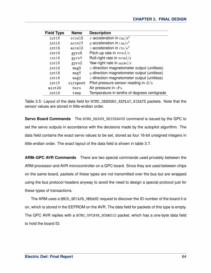
CHAPTER 3. FINAL DESIGN
Field Type Name Descriptionint16 accelX x-acceleration in cm/s2
int16 accelY y-acceleration in cm/s2
int16 accelZ z-acceleration in cm/s2
int16 gyroX Pitch-up rate in mrad/sint16 gyroY Roll-right rate in mrad/sint16 gyroZ Yaw-right rate in mrad/sint16 magX x-direction magnetometer output (unitless)int16 magY y-direction magnetometer output (unitless)int16 magZ z-direction magnetometer output (unitless)int16 airspeed Pitot pressure sensor reading in dPa
uint24 baro Air pressure in cPa
int16 temp Temperature in tenths of degrees centigrade
Table 3.5: Layout of the data field for BCMD_SENSORS_REPLAY_HIRATE packets. Note that thesensor values are stored in little-endian order.
Servo Board Commands The BCMD_SERVO_SETSERVOS command is issued by the GPC to
set the servo outputs in accordance with the decisions made by the autopilot algorithm. The
data field contains the exact servo values to be set, stored as four 16-bit unsigned integers in
little endian order. The exact layout of the data field is shown in table 3.7.
ARM–GPC AVR Commands There are two special commands used privately between the
ARM processor and AVR microcontroller on a GPC board. Since they are used between chips
on the same board, packets of these types are not transmitted over the bus but are wrapped
using the bus protocol headers anyway to avoid the need to design a special protocol just for
these types of transactions.
The ARM uses a BMCD_GPCAVR_WHOAMI request to discover the ID number of the board it is
on, which is stored in the EEPROM on the AVR. The data field for packets of this type is empty.
The GPC AVR replies with a BCMD_GPCAVR_BOARDID packet, which has a one-byte data field
to hold the board ID.
Electric Owl: Final Report 64

CHAPTER 3. FINAL DESIGN
Field Type Name Descriptionfloat32 alt Ellipsoid altitude in m
float32 epe Estimated position error in m
float32 eph Position error, horizontal in m
float32 epv Position error, vertical in m
uint16 fix Type of position fixfloat64 gps_tow GPS time of week in s
float64 lat Latitude in rad
float64 lon Longitude in rad
float32 lon_vel Longitude velocity in m/sfloat32 lat_vel Latitude velocity in m/sfloat32 alt_vel Altitude velocity in m/sfloat32 msl_hght Height above mean sea level in m
int16 leap_sec UTC leap secondsuint32 grmn_days Garmin days (since 31 Dec 1989)
Table 3.6: Layout of the data field for BCMD_SENSORS_REPLAY_LORATE packets. Taken from theGarmin Device Interface Specification [1].
Field Type Name Descriptionuint16 throttle Throttle servo settinguint16 aileron Aileron servo settinguint16 elevator Elevator servo settinguint16 rudder Rudder servo setting
Table 3.7: Layout of the data field for BCMD_SERVO_SETSERVOS packets. Note that the valuesmust be sent in little-endian order.
HITL-Only Sensors Board Commands There are also two special packet types used for
operating the system in HITL-testing mode, in which the GPC receives its sensors data from a
computer running X-Plane instead of from a sensors board. The GPC requests this data with
a BCMD_SENSORS_FETCH_AHPRS command. The data field for packets of this type is empty. The
computer replies with a BCMD_SENSORS_REPLY_AHPRS packet, which is structured as showed
in table 3.8. The data is stored in the reply packet in little-endian order.
Electric Owl: Final Report 65

CHAPTER 3. FINAL DESIGN
Field Type Name Descriptionfloat32 Gnormal Normal acceleration in G’sfloat32 Gaxial Axial acceleration in G’sfloat32 Gside Side acceleration in G’sfloat32 Q Pitch rate in rad/sfloat32 P Roll rate in rad/sfloat32 R Yaw rate in rad/sfloat32 pitch Pitch angle in rad
float32 roll Roll angle in rad
float32 hdg Heading in rad
float64 lat Latitude in rad
float64 lon Longitude in rad
float32 elev_msl Elevation above mean sea level in m
float32 hpath Horizontal pat in rad
float32 Vtrue Velocity relative to ground in m/sfloat32 VVI Vertical velocity indicator in m/s
Table 3.8: Layout of the data field for BCMD_SENSORS_REPLY_AHPRS packets.
3.5.2 Radio Downlink Protocol
The radio downlink protocol governs communications sent by the plane down to the ground
computer. In particular, it defines the structure of telemetry packets.
Packet Structure Like bus packets, downlink packets can be of variable length to handle
data payloads of varying sizes. The layout of a downlink packet is illustrated in figure 3.4.
The packet header begins with a two-byte protocol signature. After the signature is a byte
that specifies the size of the data section in bytes. Since this field is one byte, the data section
of a downlink packet may be anywhere from 0 to 255 bytes in size. The size byte is followed
by a two-byte CRC checksum, sent in big-endian order. Like the CRC checksums used in the
bus protocol, the checksum is used by the ground computer to check for transmission errors
in received packets. After the CRC is a byte that specifies the packet type, analogous to the
command byte for bus packets. The packet type byte completes the header, and the rest of
the packet consists of data.
Electric Owl: Final Report 66

CHAPTER 3. FINAL DESIGN
Note that, unlike the bus protocol, the downlink protocol does not reserve any special
bytes for frame delimiters, etc. These constructs are defined handled by separate protocol
layer used for communication with the radio board’s XTend radio module (see sections 3.1.3
and 3.2.4). Before being sent to the radio, downlink packets are wrapped using the XTend
protocol framework. At the receiving end, received packets exit the radio encased in the
XTend headers, which are stripped away to expose the underlying downlink packet. For more
information about the XTend protocol, see the datasheet for the XTend radio module [15].
Bit Offset 0-7 8-15 16-23 24-310 Protocol Signature Data Size CRC16 MSB
32 CRC16 LSB Packet Type Data64+ Data
Figure 3.4: Byte structure of a downlink packet.
Protocol Signature Protocol signature bytes were added to the downlink header in antici-
pation that the downlink protocol would evolve in the future. The signature bytes encode the
version of the downlink protocol being used. These bytes allow users to easily distinguish
between sets of hardware using different versions of the downlink protocol.
Packet Types There are three types of downlink packets. These types and the correspond-
ing values for the packet type field in the downlink packet header are given in table 3.9. Like
for bus packets, since the system uses few of the possible values for the packet type byte, it
is easy to expand the system to accommodate more packet types by defining new bytes as
needed.
Packet Type Byte DescriptionDL_TYPE_TELEMETRY 0x40 Telemetry packetDL_TYPE_STEP_READ 0x42 Read flight plan step from memoryDL_TYPE_PTR_READ 0x44 Currently executing flight plan step
Table 3.9: Downlink packet types and corresponding identification bytes.
Electric Owl: Final Report 67

CHAPTER 3. FINAL DESIGN
Telemetry Packets The most common type of downlink packet is the telemetry packet, indi-
cated by a DL_TYPE_TELEMETRY packet type byte. The structure of the data field for a telemetry
packet is similar to that for a BCMD_TELEM_REPLY bus packet: it consists of a list of telemetry
channel codes, each immediately followed by a piece of telemetry data. Multi-byte telemetry
data values are stored in the packet in big-endian order. Possible values for the telemetry
channel codes are given in table 3.10. Most of these codes are currently used by the existing
system, but a few, such as the CH_MOTOR_TACH and CH_MOTOR_CURRENT channels, have been
added in anticipation of additional features (a motor tachometer and current monitor, in the
case of the two explicitly mentioned).
As an example, a telemetry packet containing all accelerometer data would have a data
field that begins with the CH_ACCEL_AXIS1 marker, followed by two bytes of data for accelerom-
eter axis 1, MSB first. Next would come the CH_ACCEL_AXIS2 marker, followed by two bytes
of data for accelerometer axis 2. Following this would be the CH_ACCEL_AXIS3 marker and the
data for accelerometer axis 3.
Channel Byte DescriptionCH_HVBATT_VOLTAGE 0x00 High-voltage battery voltageCH_LVBATT_VOLTAGE 0x01 Low-voltage battery voltageCH_HVBATT_CURRENT 0x02 High-voltage battery currentCH_LVBATT_CURRENT 0x03 Low-voltage battery currentCH_ACCEL_AXIS1 0x04 Accelerometer axis 1CH_ACCEL_AXIS2 0x05 Accelerometer axis 2CH_ACCEL_AXIS3 0x06 Accelerometer axis 3CH_GYRO_AXIS1 0x07 Gyroscope axis 1CH_GYRO_AXIS2 0x08 Gyroscope axis 2CH_GYRO_AXIS3 0x09 Gyroscope axis 3CH_MAG_AXIS1 0x0A Magnetometer axis 1CH_MAG_AXIS2 0x0B Magnetometer axis 2CH_MAG_AXIS3 0x0C Magnetometer axis 3CH_AIRSPEED 0x0D Airspeed readingCH_MOTOR_TACH 0x0E Motor tachometer
Table 3.10: Telemetry channel types and corresponding marker bytes.
Electric Owl: Final Report 68

CHAPTER 3. FINAL DESIGN
Channel Byte DescriptionCH_MOTOR_CURRENT 0x0F Motor current drawCH_SERVO_OUT0 0x10 Servo output 0: ThrottleCH_SERVO_OUT1 0x11 Servo output 1: AileronsCH_SERVO_OUT2 0x12 Servo output 2: ElevatorCH_SERVO_OUT3 0x13 Servo output 3: RudderCH_SERVO_OUT4 0x14 Servo output 4: Manual OverrideCH_SERVO_OUT5 0x15 Servo output 5CH_BUS0_VOLTAGE 0x16 Bus 0 voltageCH_BUS1_VOLTAGE 0x17 Bus 1 voltageCH_BUS2_VOLTAGE 0x18 Bus 2 voltageCH_BUS3_VOLTAGE 0x19 Bus 3 voltageCH_TEMPERATURE 0x1A BMP085 temperature readingCH_RC_CHAN1 0x20 Received RC channel 1CH_RC_CHAN2 0x21 Received RC channel 2CH_RC_CHAN3 0x22 Received RC channel 3CH_RC_CHAN4 0x23 Received RC channel 4CH_RC_CHAN5 0x24 Received RC channel 5CH_RC_CHAN6 0x23 Received RC channel 6
CH_BUS1ERRCNT 0x30 Bus 1 packet error countCH_BUS2ERRCNT 0x31 Bus 2 packet error countCH_BUS3ERRCNT 0x32 Bus 3 packet error countCH_BUS4ERRCNT 0x33 Bus 4 packet error count
CH_ERR_SERVO_TELEM_NOREPLY 0x40 Servo data no-reply countsCH_ERR_RADIO_TELEM_NOREPLY 0x41 Radio data no-reply countsCH_ERR_RADIO_MAILBOX_NOREPLY 0x42 Radio mailbox no-reply countsCH_ERR_SENSORS_HIRATE_NOREPLY 0x43 Sensors high-rate data no-reply countsCH_ERR_SENSORS_LORATE_NOREPLY 0x44 Sensors low-rate data no-reply countsCH_ERR_SENSORS_AHPRS_NOREPLY 0x45 AHPRS no-reply counts (HITL only)
CH_RS_ACCELX_OUT 0x50 Count of x-accelerometer outliersCH_RS_ACCELY_OUT 0x51 Count of y-accelerometer outliersCH_RS_ACCELZ_OUT 0x52 Count of z-accelerometer outliersCH_RS_GYROX_OUT 0x53 Count of x-gyroscope outliersCH_RS_GYROY_OUT 0x54 Count of y-gyroscope outliersCH_RS_GYROZ_OUT 0x55 Count of z-gyroscope outliersCH_RS_MAGX_OUT 0x56 Count of x-magnetometer outliersCH_RS_MAGY_OUT 0x57 Count of y-magnetometer outliersCH_RS_MAGZ_OUT 0x58 Count of z-magnetometer outliers
CH_RS_AIRSPEED_OUT 0x59 Count of airspeed outliersCH_RS_BARO_OUT 0x5A Count of barometer outliersCH_RS_TEMP_OUT 0x5B Count of temperature outliers
Table 3.10: Telemetry channel types and corresponding marker bytes.
Electric Owl: Final Report 69

CHAPTER 3. FINAL DESIGN
Channel Byte DescriptionCH_EXT_AIR_TEMP 0x80 External air temperature
CH_GPS_FIX_STATUS 0x81 GPS fix statusCH_MANUAL_OVERRIDE 0x82 Manual override status, 1 = override
CH_FP_POINTER 0x90 Flight plan pointerCH_RED_VOTING_MATRIX 0x91 Redundancy failure voting matrixCH_RED_WORKING_SET 0x92 Redundancy working set
CH_PRESS_ALT 0xC0 Pressure altimeterCH_GPS 0xC1 GPS sentences
CH_STATE_LAT 0xD0 State vector: latitude (degrees)CH_STATE_LON 0xD1 State vector: longitude (degrees)CH_STATE_ALT 0xD2 State vector: altitude (meters msl)
CH_STATE_HEADING 0xD3 State vector: heading (radians)CH_STATE_PITCH 0xD4 State vector: pitch (radians)CH_STATE_ROLL 0xD5 State vector: roll (radians)CH_STATE_VEL_X 0xD6 State vector: x-velocityCH_STATE_VEL_Y 0xD7 State vector: y-velocityCH_STATE_VEL_Z 0xD8 State vector: z-velocityCH_STATE_GNDSPD 0xD9 State vector: ground speedCH_STATE_AIRSPD 0xDA State vector: air speedCH_RADIO_ERRCNT 0xE0 Radio error count
CH_FP_STEP 0xF0 Flight plan stepCH_GLIDE_HDG 0xF1 Desired glide heading
Table 3.10: Telemetry channel types and corresponding marker bytes.
Flight Plan Query Replies The other types of downlink packets are used as replies to
queries from the ground computer about the state of the flight plan currently stored on the GPC.
The DL_TYPE_PTR_READ packet type is used to reply to uplink packets of type UL_TYPE_PTR_READ
(see section 3.5.3) and have a data section consisting of a single byte, which holds the number
of the current step.
Similarly, the DL_TYPE_STEP_READ packet type is used to reply to uplink packets of type
UL_TYPE_STEP_READ (see section 3.5.3). The data section of a DL_TYPE_STEP_READ packet
consists of a flight plan step, laid out as specified by the flight plan mechanism (see section
Electric Owl: Final Report 70

CHAPTER 3. FINAL DESIGN
3.3.3) followed by a single byte that is the number of the step that was read.
For more information about flight plans, see section 3.3.3.
3.5.3 Radio Uplink Protocol
The radio uplink protocol specifies the structure of communications sent from the ground com-
puter to the UAV. Importantly, it dictates the procedure for uploading flight plans to the plane.
The chief reason for having a different protocol to govern uplink operations instead of just
using the downlink protocol for bidirectional communication is security. Uplinked commands
need to be received by the UAV securely and reliably in order to ensure that the plane behaves
as desired and is not “hijacked” by unwanted third parties. This entails the addition of a few
extra fields to the packet header, as described below. By contrast, downlink communications
need as much bandwidth as possible so that telemetry may be transmitted to the ground at the
fastest possible rate. Thus, for downlink packets, keeping the packet overhead to a minimum
is desirable.
Packet Structure The structure of an uplink packet is depicted in figure 3.5. The uplink
packet header begins with a two-byte protocol signature, followed by a 32-bit message au-
thentication code (MAC). This is succeeded by a 32-bit sequence number, and the header is
completed with a byte that identifies the type of uplink packet. The rest of the uplink packet
contains data pertinent to the packet type.
Note that, unlike downlink packets, uplink packets do not have a field for specifying data
size. The data fields of all uplink packet types have fixed, known sizes, and so sending a size
byte along with the packet is unnecessary.
Protocol Signature Like for the downlink protocol, uplink packets have a two-byte protocol
signature field that specifies the version of the uplink protocol in use. See the paragraph in
Electric Owl: Final Report 71

CHAPTER 3. FINAL DESIGN
Bit Offset 0-7 8-15 16-23 24-310 Protocol Signature MAC32
32 MAC32 Sequence Number64 Sequence Number Packet Type Data96 Data
Figure 3.5: Byte structure of an uplink packet.
protocol signatures in section 3.5.2 for more information.
Message Authentication Code The uplink protocol provides a mechanism for verifying the
authenticity of received uplink commands in the form of a 32-bit message authentication code
(MAC) attached to each uplink packet. Matching encryption keys are stored on the UAV and
on the ground computer. When the ground computer sends an uplink packet, it uses its key
and cryptographic hashing algorithm to produce a 32-bit digest of the contents of the uplink
packet and attaches this digest to the packet as the MAC. When the plane receives an uplink
packet, it uses its key and the same hashing algorithm to produce its own digest of the uplink
contents, which is then compares to the MAC sent with the packet. If the values match, the
packet is very likely to have come from the ground computer.
In addition to being used for authenticity verification, the MAC also plays the role of the
16-bit CRC checksum in the downlink protocol. If a transmission error occurs, the digest
computed onboard the plane will very probably not match the sent MAC, enabling such errors
to be detected.
Sequence Numbering Every uplink packet sent to the plane from the ground computer is
given a 32-bit sequence number, analogous to sequence numbers in TCP/IP packets. The
sequence number plays two roles. First, it can be used to detect lost transmissions. If the
plane receives two uplink packets which do not directly follow each other in sequence (i.e.,
have sequence numbers that differ by more than 1), then there must have been a packet
transmitted in between them that the plane did not receive. The plane can then send a packet
Electric Owl: Final Report 72

CHAPTER 3. FINAL DESIGN
to the ground computer requesting re-transmission of the lost data (though this has not yet
been implemented). This is especially important for ensuring the integrity of flight plan upload
(see section 3.3.3), since flight plan steps must be updated in a specified order.
Second, the sequence number bolsters system security by guarding against potential
packet replay attacks. If uplink packets were not numbered, an attacker could conceivably
“sniff” an uplink command out of the air and then re-transmit it. This could have disastrous
effects if the plane carries out the instructions contained within the re-transmitted packet, such
as overwriting the current flight plan. With the sequence number, the plane can know if a
packet has already been transmitted once and ignore it if so.
Packet Types Presently, there are two main categories of uplink packet: joystick packets
and packet types that are used for changing the plane’s onboard flight plan. The type of an
uplink packet is determined by its packet type field. Possible values for the packet type byte are
given in table 3.11. Just as for bus and downlink packets, new uplink packets can be defined
by specifying new values of the packet type byte.
Packet Type Byte DescriptionUL_CMD_JOYSTICK 0x10 Human-input joystick controlUL_CMD_STEP_WRITE 0x20 Write flight plan entryUL_CMD_STEP_READ 0x21 Read back flight plan entryUL_CMD_PTR_WRITE 0x22 Set current flight plan stepUL_CMD_PTR_READ 0x23 Read which flight plan step is currently executing
Table 3.11: Downlink packet types and corresponding identification bytes.
Joystick Packets Joystick packets have type UL_CMD_JOYSTICK and are sent when the
plane is being flown under PC joystick control from the ground computer. The data section
of these packets contain servo output values to be used directly by the servo board for control-
ling the servos. The servo values are stored as 16-bit unsigned integers in big-endian order
and are laid out as shown in table 3.12.
Electric Owl: Final Report 73

CHAPTER 3. FINAL DESIGN
Field Type Name Descriptionuint16 throttle Throttle servo settinguint16 aileron Aileron servo settinguint16 elevator Elevator servo settinguint16 rudder Rudder servo setting
Table 3.12: Layout of the data field for UL_CMD_JOYSTICK packets.
Flight Plan Packets There are four types of packets used to for reading and changing the
plane’s on-board flight plan (see section 3.3.3) from the ground computer. Packets of type
UL_CMD_PTR_READ are sent to request the number of the flight plan step that the plane is
currently executing. The data section for such packets is empty. Similarly, UL_CMD_PTR_WRITE
packets are used to set the plane to execute a specific step in the current flight plan. The
data field for packets of this type consists of a single byte: the number of the step to begin
executing.
UL_CMD_STEP_READ commands are sent to read back the flight plan entry for a specific
flight plan step. The data field for such packets contains one byte that holds the number of
the step to read back. Likewise, UL_CMD_STEP_WRITE commands can be used to write a new
entry to the onboard flight plan. The data section of UL_CMD_STEP_WRITE packets consists of
a flight plan step laid out as specified by the flight plan mechanism (see section 3.3.3) followed
immediately by one byte indicating the step to modify.
3.6 Prototype Aircraft Hardware
3.6.1 Airframe
In order to simplify development, a popular oversized hobby R/C aircraft was chosen to carry
the avionics package. This aircraft, the Senior Telemaster from Hobby-Lobby, is a high-wing
monoplane with a 7 foot 10 inch wingspan, conventional landing gear, and lifting tail. In the
absence of the avionics package, the plane weighs about 11 pounds including motor, servos,
Electric Owl: Final Report 74

CHAPTER 3. FINAL DESIGN
battery, R/C receiver, and landing gear.
Features The Senior Telemaster is an exceptionally stable, slow flying, and generally well
behaved aircraft, and this simplified autopilot development considerably. The fuselage of the
plane is very open and has significant free space for payload, thus allowing flexibility in po-
sitioning the avionics and auxiliary sensors. The plane is quite light for its size, while still
remaining relatively durable.
Limitations The chosen aircraft does suffer from two limitations: high parasite drag and the
conventional landing gear. The high drag is not particularly important for testing the avionics
package, but renders the plane quite unsuitable for high altitude flights or flights lasting over an
hour. The conventional landing gear complicates the takeoff roll because it makes the plane
unstable in yaw. This effect is particularly noticeable on grass fields. The small tail wheel is
also not very stable and is easily damaged, furthermore, damage to the tail wheel tends to
propagate up into the tail assembly.
Revision History The first prototype, the “OWLbatross”, was built from a kit by Mr. Brockman
when he was in high school. This prototype was modified to have a tricycle landing gear with
a steerable nose wheel instead of a conventional landing gear. This modification increased
weight and drag but greatly improved taxi and takeoff controllability. The first prototype also
had only one servo for controlling both ailerons. Although this decreased drag, it required the
servo to be larger and specialized, as well as decreased the volume available for payload. The
first prototype also had only one elevator surface driven by one servo.
The fuselage of the “OWLbatross” was destroyed during the first test of the sensor board
because the center of gravity was too far aft. Wind gusts were a contributing factor in the
crash. The motor, batteries, servos, and avionics survived the crash largely unharmed. The
wing was slightly damaged and was retained as a spare.
Electric Owl: Final Report 75

CHAPTER 3. FINAL DESIGN
Because of the time and expense of assembling and covering the balsa airframe, a second
backup prototype, the “FOWLcon”, was purchased in an almost-ready-to-fly (ARF) condition
from the manufacturer. Replacement parts for the ARF prototype are quite inexpensive, with
the entire fuselage costing a mere $40. Several spare fuselages and tail assemblies, as well
as one spare wing, are kept on hand in case the originals are damaged in a crash.
After the destruction of the first prototype, it was determined that modifying subsequent
prototypes to have a tricycle landing gear would take too much time and would distract from
the immediate focus of the project, so the second (and current) prototype retains its stock
conventional landing gear.
Repairs Cyanoacrylate glue was used for the vast majority of the wood assembly and repair.
The entire fuselage and wings were originally covered with an inexpensive low-temperature
mylar coating from the factory. Where this has been damaged, it has been replaced with
superior high-temperature “Super Monokote” from Topflite. Special care had to be taken to
avoid burning the original covering at the interfaces between the original covering and the
patches.
Landing Gear The stock landing gear has several inadequacies which have been addressed
with varying degrees of success. The foam main wheels shipped with the kit are too easily
damaged and have been replaced by DuBro rubber wheels. The tail wheel has likewise been
replaced – although the current tailwheel is sturdier, it is not currently connected to the rudder
and thus is not steerable, limiting low-speed taxi steering.
3.6.2 Power System
Propulsion for the plane is provided by an electric brushless motor from AXI, the 4130/20. This
motor is capable of delivering over 1000W of power to the propeller when equipped with an
Electric Owl: Final Report 76

CHAPTER 3. FINAL DESIGN
8S1P Lithium-polymer battery and the correct 14x10 propeller. The smaller 7S1P 5000mAh
battery actually used decreases thrust somewhat, but the motor remains greatly overpowered,
causing the plane to be able to take off in less than 15 meters with no wind and full payload.
A smaller motor, the 4120/16, was also acquired, but the lighter weight of the motor made
managing the center of gravity of the plane more difficult, so its use was discontinued.
As of the time of this report, the 4130/20 motor makes a high-pitched whine when operated
above 80% throttle setting. This may indicate that the motor was damaged slightly during the
crash which destroyed the first prototype’s fuselage.
Since the motor is AC, the DC voltage from the battery must be converted with a JETI
motor controller rated for 70 amps. This motor controller is connected to the servo control
board, which sees it as a normal servo, thus allowing the avionics to control the throttle.
Alternative Propulsion The chosen electric motor is less powerful and has significantly less
range than the glow-fuel motor that the plane was originally designed for, a 0.60 cubic inch 2-
cycle motor capable of generating 1.8 horsepower. The electric motor was chosen because
it is much safer and more reliable than the glow-fuel motor. The glow-fuel mixture contains
about one-third castor oil for lubrication, a considerable amount of which ends up coating the
wings and tail of the plane with sludge after a flight. Starting the glow-fuel motor requires
standing precariously close to the propeller, which is smaller and runs at twice the RPM of the
electric motor. The glow-fuel motor’s carburetor, located about an inch behind the spinning
propeller, regularly requires hand adjustment while running. The glow-fuel motor also has a
nasty tendency to stall while climbing if the carburetor is incorrectly adjusted; the procedure for
avoiding this is to hold the plane straight up in the air and apply full power to check for proper
operation.
Electric Owl: Final Report 77

CHAPTER 3. FINAL DESIGN
3.6.3 Actuators
The plane has four flight controls: ailerons to control roll rate, elevators to adjust angle of
attack, throttle for climb rate, and rudder for ground steering and to compensate for the adverse
yaw effect caused by the ailerons. The current prototype has a separate servo for each aileron;
they are wired together to form a single PCM channel for control. Throttle control is provided
by the motor controller as described earlier. The rudder is controlled by a single servo, while
the elevator is split into two independent sections, each connected to its own servo. Like the
aileron servos, the two elevator servos are wired together to form a single PCM channel. All
of the servos are of the same standard model, the Hitec HS-322HD.
The servos are connected to the appropriate flight control surface with control rods. The
control rods for the ailerons are metal with plastic clevises connecting them to plastic con-
trol horns on both ends. Small sections of fuel tubing have been used to secure the plastic
clevises. The elevator control rods are carbon fiber, while the rudder control rod has been
replaced with steel to prevent flutter. Both elevator and rudder control rods are connected to
plastic control horns on both ends with metal clevises secured with metal locking clips.
The stock radio control receiver used for manual override is the 2.4 GHz Spektrum AR6200.
Because of limited servo cable length and the need for the servo board to be between the
manual override receiver and the servos, the receiver is located right next to the servo board.
The receiver has a remote which is located in the tail assembly and is oriented at right angles
to the main receiver to improve reception.
3.6.4 Avionics Mounting
The avionics suite has been mounted in the plane in a crude but effective manner. The main
backplane has been glued to square balsa dowels which have in turn been glued to the bottom
of the main compartment. The rest of the modules plug into the backplane, while two notched
Electric Owl: Final Report 78

CHAPTER 3. FINAL DESIGN
balsa sticks glued to the sides of main compartment serve to prevent the modules, especially
the sensors boards, from moving. The modules are not at present held in place from the top,
since the connectors to the backplane seem to be stiff enough.
The servo board is installed in the slot closest to the front of the plane to allow space for
the large number of servo and receiver wires, as well as to shorten the wires running to the
primary and secondary batteries in the battery compartment. The positioning of the other
modules is somewhat arbitrary, although keeping the telemetry radio antenna connection far
from the servo board and servo wires helps decrease servo jitter from EMI.
3.6.5 Non-Integrated Sensors
In the present configuration, the plane has two Garmin 18x LVC OEM GPS units for navigation.
One of these is integrated into the wing, while the other is located above the main battery in
the battery compartment behind the motor. The GPS units are intentionally kept far apart to
avoid oscillator interference. The units are secured from moving with double-stick foam tape.
The pitot-static tubes extend from holes drilled in each wing about half-way to the wing
tips. This positioning keeps them out of the propeller wash which would impair accuracy. The
pitot-static tubes are glued into the wings and are each connected to two lengths of medical
tubing. This flexible tubing runs along the inside of the wing and emerges from the wing in the
center where it can be connected directly to the sensors board.
3.7 Future Expansion
When considering the modular architecture used for this project, thought was given to imple-
menting full redundancy, even though this is outside the scope of the project for this year. After
considering the design of current NASA space systems, including manned vehicles like the
Space Shuttle [9] [17] and autonomous probes like the Mars Reconnaissance Orbiter [4] [5]
Electric Owl: Final Report 79

CHAPTER 3. FINAL DESIGN
[6]. Other inspiration came from the redundant systems used on commercial airliners [18].
This plan calls for redundant placement of all of the boards, rather than only the sensors. This
system would resemble the one shown in 2.1.
Servo Boards With the design of the servo board, it should be possible to drop in multiple
boards, although this requires redundant external control surfaces, which significantly adds to
the weight of the airframe. Multiple power supplies should be supported transparently.
Radio Boards If the code for the bus master is changed somewhat, it should be possible
to add a second radio board in a failover capacity, where only one functions until failure is
reported. With the radio board, loss of signal can be interpreted as a failure, and the backup
system can be activated.
GPC Boards With significant software upgrades, up to four GPC boards could be expected
to work together in lockstep operation, based on the design of the Space Shuttle [9] flight
computer architecture. In this situation, each of the GPC boards controls a bus, and operation
proceeds with a single bus until the non-primary boards detect an error, and then disable the
faulty GPC.
Four GPC boards were selected to provide failsafe, fail-operational behavior. Specifically,
the first failure is easily detected as a difference between one computer and the other three.
Note that two pairs of computers reaching two separate conclusions is extremely unlikely be-
cause it depends on at least two computers failing in identical ways. After one GPC has been
marked inoperative, the remaining three boards still form a voting set, and can correctly detect
errors. After a second failure, the system is reduced to two working boards, and is forced to
depend on heuristics to determine which board is faulty if the two differ.
Electric Owl: Final Report 80

CHAPTER 3. FINAL DESIGN
3.8 Errata and Revision History
The electrical hardware within the aircraft has undergone three major revisions.
3.8.1 Hardware Revision I
The first revision of the hardware was ordered in July 2010. Only the servo board was ordered
and populated. This allowed the team to produce initial firmware, implementing the manual
override, and allowed initial flight testing.
The following is a complete list of known errata for Servo Rev 01:
• All Schottky diode silkscreens (D40, D50, D60, D70) show the line at the wrong end of
the diode.
• The SOT23-6 footprints (U30, U31) do not have any orientation marker.
• The power jumper section could be improved by adding labels to indicate which side is
LV_BUS and which HV_BUS.
• The servo wire holes (S_IN1 thru S_IN6, LV_BATT) are too small for the 22 gauge
stranded wires to easily fit in. Also, putting the wires straight in like that may lead to
early stress breaking.
• The ground plane vias near U40 and U60 should probably be filled-in style, instead of
thermal relief style.
• The HV battery connector should have reverse polarity protection in the form of either a
crowbar diode and fuse, crowbar zener diode and fuse, or forward bias Schottky diode.
• Current sense outputs have no low-pass filtering.
Electric Owl: Final Report 81

CHAPTER 3. FINAL DESIGN
• There is no good reason not to add more bypass capacitors to the input of U21 and the
outputs of U21 and U22.
• To increase safety, a different connector should be used for HV_BATT which has more
physical spacing between the pins.
• Board fails to power up with just the HV battery. This problem only manifests if you try
to transition from fully off (no LV battery, no external power on buses 0-3) to connecting
the HV battery input. The HV_Shutdown line is held low by the Vcc static protection
diodes on the ATxmega32A4. As a workaround, cut the HV_Shutdown trace between
the XMEGA and the LM2676S-12 (not yet tested). In the future, this straight wire will be
replaced with a MOSFET and a gate pull-down resistor.
• LED missing.
3.8.2 Hardware Revision II
The second revision of the hardware reduced the height of all of the boards to ease fitting them
into the aircraft. All of these boards were built and tested. An improper option in one of the
software packages resulted in several mis-labelings of components on the silkscreen.
It was discovered that the yaw gyro on the sensor board was ordered incorrectly, and the
desired part was no longer available, which required the creation of the third revision. The
remainder of this section documents known errata with this series of boards.
Backplane 02
• Mounting holes in bottom (try not to expand total area).
• Missing board revision text.
• Additional timing lines (2) would be useful for synchronization.
Electric Owl: Final Report 82

CHAPTER 3. FINAL DESIGN
Servo 02
• Silkscreen labels for R87 and R89 are swapped in location.
Sensors 02
• Silkscreen for C4A sucks.
• R81, R82, R83, and R84 should be moved right near U5 to reduce EMI pickup concerns.
• Silkscreen for R54 and C55 are reversed. (Accelerometer channel Y)
• ATXMEGA32A4 errata number 7 applies to the ADC: several ADC samples must be
junked after switching the input MUX.
• An analog output version of the LY530AL chip is available as the LY530ALH, which could
be used with the other analog inputs on the AVR.
• U41 (LY530AL) has CS pin 10 connected to ground instead of Vdd_IO. This forces the
chip into SPI mode, when it should be in I2C mode.
• C81 needs to be low-ESR.
• GPS PPS line should be accessible (ideally through backplane timing lines).
GPC 01
• The USB connector is placed backwards on the board.
• The mounting holes on the USB connector are too small.
• Silkscreen labels for R34, R30, and R35 are obscured by vias.
• TST line is not accessible via jumper.
Electric Owl: Final Report 83

CHAPTER 3. FINAL DESIGN
• Need to allocate a pin on the ARM for the AVR to use to trigger an interrupt upon com-
plete receipt of a bus packet.
3.8.3 Hardware Revision III
The third revision of the hardware adds mounting holes to the circuit boards, and fixes the
yaw gyro issue in the servo board by replacing it with the analog sensor that was mistakenly
ordered.
Backplane 03
• Labels should be added to the bus connectors to simplify use.
Sensors 03
• The EOC pin on the Bosch BMP085 pressure sensor is not connected to anything. Hook-
ing up to a pin on the AVR would save the need to use a timer/counter to delay for 25.5
ms while waiting for the sensor to complete a conversion.
GPC 02
• The numbering of GPC boards is confusing. This originated because the second revision
of the hardware was the first to include the GPC board. In the future, the numbers should
be aligned.
Electric Owl: Final Report 84

4 Testing and Results
4.1 Basic Functionality Testing
4.1.1 Electrical Testing
The electrical connectivity of each circuit board was thoroughly checked after assembly with a
digital multimeter (DMM) before the board was ever powered up for the first time. This allowed
the team to detect electrical problems due to open or shorted traces before they could damage
any of the sensitive chips.
Once a board passed its check for opens and shorts, it was attached to a backplane and
powered up. The DMM was again used to verify the voltage levels at the output of each
board’s power regulators were correct. If they were, then the team would attempt to program
the board’s AVR microcontroller with its assigned board ID (see section 3.2) and then with
the main set of firmware. If the programming was successful, the board was then checked to
ensure that all features of the current version of the firmware worked properly.
4.1.2 Software Testing
The team performed basic testing of the software functionality on an ad-hoc basis, vetting out
each new feature as it was added. This was typically accomplished by having each board
being tested print debug text to an unused system bus and using the serial terminal program
minicom to read it out on the PC.
Once the bus protocol was developed, the need arose to test the ability of the boards
to reply correctly to bus packets addressed to them. Before the development of the GPC
firmware, this was usually accomplished using some simple test programs written for the PC
that would inject packets onto the system bus. The board’s reply would then be captured using
Electric Owl: Final Report 85

CHAPTER 4. TESTING AND RESULTS
minicom or the busmonitor or busmonitor2 programs (see section A.6). Once the basic GPC
firmware was written and the logging features of the Houston ground software were developed,
these programs were set aside in favor of using the GPC board to send packets and Houston
to monitor the replies.
4.1.3 Sensor Redundancy Testing
Ground testing of the sensor redundancy was performed by using the GPC’s debug console to
continuously print information about the sensor data it had received and how it was processing
it. The debug stream was then carefully checked to make sure that the results of its processing
conformed to the desired behavior outlined in section 3.3.2. In particular, the team was able to
confirm the correct operation of the outlier rejection procedure by watching the GPC identify
and set aside wild values from one of the noisier pitch gyroscopes on one of the sensors
boards.
The team also performed tests in which all three redundant sensors boards were loaded
into the airplane and the GPC was programmed to maintain a fixed pitch. Tilting the airframe
off-pitch would cause the GPC to respond by moving the plane’s elevator to compensate. The
team then yanked the sensors boards out of the airframe one-by-one to confirm that the plane
could react to the loss of sensor data on the fly and still respond correctly when tilted.
Finally, the team also tested the ability of the system to process redundant sensor data in
a real flight environment. The results of the flight test are described in section 4.4.6.
4.2 Sensors Calibration
Before the sensors could be used to determine the plane’s orientation, they first had to be
calibrated to remove zero-offsets and scale their outputs into the ranges expected by the au-
topilot algorithm. This section describes the team’s general approach to sensor calibration.
Electric Owl: Final Report 86

CHAPTER 4. TESTING AND RESULTS
For specific step-by-step calibration procedures using the programs and scripts developed,
see section A.7.
Accelerometers Each axis of the three-axis accelerometer is calibrated individually. First,
the sensors board is oriented such that the axis to be calibrated is aligned pointing directly
at the ground. Several measurements are taken with the accelerometer in this configuration
and then averaged together (to curtail noise) to form an estimate for the sensor’s value with
the axis aligned with the direction of gravity, i.e., for an acceleration of 1 G. Next, the board is
rotated such that the axis to be calibrated is aligned pointing directly upward. Again, several
measurements are taken and averaged together, this time to get an estimate of the sensor’s
value with the axis antiparallel to the direction of gravity, i.e., for an acceleration of -1 G.
These two points lie on a line. The slope and vertical intercept of this line can be used
to correct for any zero-offsets and to scale the axis output into the same range as that of the
other axes.
This calibration procedure cannot correct for cross-axis correlations due to non-orthogonality
of the axes; however, practice has found these effects to be negligible and the above procedure
to be adequate.
Magnetometers Ideally, the magnetometers could be calibrated in the same way as the
accelerometers, one axis at a time, using the Earth’s native magnetic field as a reference
the same way that the Earth’s gravitational field serves as a reference for the accelerometers.
Unfortunately, while the Earth’s magnetic field is locally of approximately constant strength and
uniform direction (when away from buildings and large metal objects) as desired, it is difficult to
precisely determine the field direction. Knowing the field direction is important because it gives
the direction along which the magnetometers should register their largest values. Knowing
this maximum is critical for choosing scaling constants that make the magnetometer values
range as large as possible for maximum sensitivity while keeping it confined to the range
Electric Owl: Final Report 87

CHAPTER 4. TESTING AND RESULTS
representable using a 16-bit integer type. Thus, a slightly different calibration technique had
to be developed.
The procedure the team came up with is as follows. The Earth’s magnetic field is still used
as a reference, but instead of trying to take measurements along each axis separately, a large
number of measurements from all three axes are taken simultaneously with the magnetometer
oriented in a variety of different directions. These measurements are then plotted as points
in three-dimensional space (one coordinate dimension for each axis of the magnetometer),
where they form an ellipsoidal point cloud. By taking a large number of measurements with
the sensor oriented in many different directions, the equation of this ellipsoid can be deter-
mined. The coordinates of the centroid of this ellipsoid gives the zero-offsets for each of the
magnetometer axes, and the lengths of the ellipsoid axes can be used to adjust the relative
scaling of the magnetometer axes.
To do the curve fitting, the team cast the problem as a non-linear least squares optimization
problem in six dimensions (three for the coordinates of the centroid, three for the axis lengths)
and used MATLAB’s lsqnonlin routine to solve for the optimal set of parameters. lsqnonlin
uses a trust region method to perform optimization. For more information, see the MATLAB
manual page for lsqnonlin and the papers [19] and [20].
Gyroscopes Calibration of the gyroscopes requires a souce of constant angular rotation.
The team procured a standard 3313
RPM record player for this purpose, measured its rate
of rotation, and took gyroscope measurements with the boards placed on the rotating plat-
form. To avoid the need to hook cables up to the rotating assembly to tap into the bus, the
measurements were sent wirelessly to a PC using the radio link.
Two measurements were taken for each gyroscope axis: one with the system rotating
about the axis at the turntable speed and one with the boards in a stationary, non-rotating
configuration. The team used these data to generate a linear model for the behavior of the
Electric Owl: Final Report 88

CHAPTER 4. TESTING AND RESULTS
gyroscopes.
Relative Airspeed To calibrate the differential pressure sensor used for measuring the plane’s
indicated airspeed, the team connected one of the pitot tubes that had been purchased for
use with airspeed measurement to the sensor’s input ports and mounted the tube inside a
wind tunnel. Several pressure measurements were taken with the wind tunnel set to produce
airstreams with a variety of flow rates between 10 and 30 mph. At the same time, the team
recorded the readings of the wind tunnel’s own pitot-static pressure measurement system and
used these to compute a linear model for the behavior of the pressure sensor.
4.3 Hardware-in-the-Loop (HITL) Simulation
To enable ground development and testing of the autopilot algorithm, the team created a
hardware-in-the-loop (HITL) test framework centered around the commercially available flight
simulator X-Plane [21]. The term hardware-in-the-loop refers to the fact that the autopilot
algorithm is running on the actual GPC hardware during the test (as opposed to a software-in-
the-loop test, in which the algorithm would be running inside a software emulator for the GPC
ARM).
To perform HITL testing, the only change to the firmware that must be made is that the GPC
board must be programmed to handle sensor data from X-Plane instead of from a sensors
board. During each pass of the main system loop, the GPC requests data from X-Plane
by sending a BCMD_SENSORS_FETCH_AHPRS request packet out on the system bus (see section
3.5.1). This is picked up by the Houston ground software, which is listening to traffic on the bus
as part of its HITL testing mode (see section 3.4). Houston then retrieves airplane state data
from X-Plane, wraps it in a BCMD_SENSORS_REPLY_AHPRS packet, and sends it on to the GPC.
The GPC takes the data it has received and inputs it into the autopilot algorithm, which decides
how to manipulate the control surfaces to best adhere to the programmed flight plan. The GPC
Electric Owl: Final Report 89

CHAPTER 4. TESTING AND RESULTS
then sends these manipulations out over the bus in the form of a BCMD_SERVO_SETSERVOS
packet. Houston picks this up and forwards the data to X-Plane, which uses this information
and its internal flight model to update the state of the simulated aircraft.
The team made extensive use of the HITL test framework for trying out changes to the
autopilot prior to actual flight tests and for tuning autopilot control loop constants to improve
the dynamic behavior of the aircraft. This required the team to construct a simple X-Plane
model of the prototype Senior Telemaster used as the test airframe.
Most importantly, the team used the HITL framework to demonstrate the ability of the au-
topilot to successfully follow a series of waypoints. For instance, in one particular test, the
GPC was programmed to fly repeatedly in a box-like pattern through a series of waypoints
whose coordinates form the four corners of a rectangle. The plane exhibited some position
overshoot as it turned when proceeding from one waypoint to the next but otherwise tracked
the expected path reasonably well.
4.4 Flight Tests
In order to demonstrate the functionality of the system in a real flight environment, the team
conducted a series of flight tests over the course of the year. Each flight test was performed
with the aim of demonstrating a specific feature. This section catalogues all the flight tests that
the team carried out, their purposes, and their results.
4.4.1 Servo Board Flight Test: 08/22/2010
The purpose of this flight test, which was conducted at the end of the summer, just prior to the
start of the Fall, 2011 term, had two goals. First, At this point in time, the team had just finished
writing the first version of the firmware for the servo control board and wanted to verify that the
manual override feature worked properly. In this test, the team was able to successfully fly the
Electric Owl: Final Report 90

CHAPTER 4. TESTING AND RESULTS
plane under manual control with only the servo board installed, operating in manual override
mode. This confirmed the ability of the servo board to take correctly receive and process input
from the manual RC receiver and also to provide control pulses to each of the servos with the
appropriate timing and duration.
The second goal of this test was to verify the operation of the power supplies on the servo
board (which would eventually be used to power the complete avionics package; see section
3.1.2) under real flight conditions. The team was concerned that the high current draw from the
plane’s powerful electric motor might cause microcontroller resets, which would necessitate a
hardware revision with re-designed power supplies. Fortunately, these were not observed, and
the system appeared to operate correctly.
4.4.2 Three-Board Flight Test: 01/07/2011
Over the course of the Fall, 2011 term and the winter recess, the team worked on developing
the bus protocol, wrote the firmware for the radio board, and wrote a first draft of the GPC
firmware that was not based on the MAL kernel, which was still being developed. In particular,
the basic facilities for command uplink and telemetry downlink had been established.
The goal of the three-board flight test was to try out these facilities and see what needed
to be improved. The test was dubbed the “three-board” flight test is because the test involved
three of the four types of circuit boards: the GPC board, the radio board, and the servo board.
The GPC was programmed to retrieve bus and battery voltages and battery currents from the
servo and radio boards and downlink them over the radio, where they would be picked up by
the ground software. The team had also developed some code for flying the plane using a PC
joystick and planned to use this to test the ability of the plane to receive uplinked commands.
Unfortunately, the flight test ended too quickly for any of these facilities to really be exer-
cised. Due to what was later determined (using video analysis) to be a misbalanced center
of gravity, the plane crashed after about five seconds of flight, shattering the front end of the
Electric Owl: Final Report 91

CHAPTER 4. TESTING AND RESULTS
airframe and causing the electronics to become ejected from their mounted positions. On the
other hand, the team was able to successfully collect a handful of telemetry frames, demon-
strating that the telemetry downlink worked. The team’s experience with decoding the down-
linked packets also led the team to re-design the telemetry logging capabilities of the ground
software and spurred the development of the logging protocol (see section 3.4.5), in particular.
4.4.3 Initial Autopilot Flight Test: 03/06/2011
The next flight test the team conducted was aimed at demonstrating basic autopilot function-
ality by having the plane maintain a fixed horizontal path. By this time, the team had written
firmware for all of the different boards, calibrated all of the sensors except for the airspeed
sensor, and integrated the autopilot code into the GPC firmware.
In order to avoid the problem with the plane’s center of gravity that caused the previous
flight test to end prematurely, the team had some of the experienced RC pilots at the flying
field help check to ensure that the plane was properly balanced. Additionally, since the team’s
experience flying RC aircraft is relatively limited, the team enlisted the help of one of the pilots,
Mr. Keith Klix, in flying the aircraft under manual control to reduce the risk of damaging the
airframe during takeoff and landing.
Mr. Klix flew the plane up to a reasonable altitude and then turned control over to the autopi-
lot by engaging the manual override switch on the RC transmitter. The plane was programmed
to fly in a straight line, adhering to the horizontal path it was last on before the autopilot was
engaged. While the plane appeared to try and maintain this path as programmed, it exhibited
substantial undesirable oscillations in its heading. At the end of the test, Mr. Klix landed the
plane perfectly, leaving the hardware in good condition for future testing.
Though the autopilot did not perform quite as well as the team had hoped, this test was
valuable because it was the first test of the fully integrated system in a real flight environment.
The team successfully collected a full stream of telemetry data from the flight, including sensor
Electric Owl: Final Report 92

CHAPTER 4. TESTING AND RESULTS
values and the autopilot’s estimates of the plane’s state for every flight frame. This gave strong
confirmation of the correct operation of the radio downlink and gave the team some data to
analyze to improve the autopilot for the next flight.
4.4.4 Basic Autopilot Flight Test: 03/19/2011
After the previous test, the team made some modifications to the autopilot to try and fix the
oscillating behavior that had been observed. Specifically, the autopilot code was altered to try
and maintain a fixed heading for the aircraft instead of a fixed horizontal path as was done
previously. After performing a successful short flight test at a nearby location to see if the
changes looked like they would work, the team traveled out to Dick Scobee Field on March
19, 2011 try a longer flight test and gather more data. Additionally, the team had finished
calibrating the airspeed sensors and installing a pitot tube in the plane’s wing, so the team
hoped to use this flight test to collect airspeed data for the first time.
As in the flight test that was conducted on March 6, the team had one of the experienced
pilots at the field fly the plane to a reasonable altitude and engage the autopilot. The plane
was programmed to try and maintain its last heading just prior to the transition to autopilot.
The autopilot performed well, and the magnitude of the oscillation in the plane’s heading while
under automatic control appeared to have been reduced substantially from the previous flight
test. With some advice from the pilot about the plane’s handling, the team adjusted some
of the control constants in the autopilot feedback loop and conducted a second flight. With
these improvements, the autopilot performed even better, maintaining its heading with even
less oscillation than before.
As with the previous flight test, the team collected a full stream of telemetry data and used
this to gauge the autopilot’s performance and find ways to improve it for the next test.
Electric Owl: Final Report 93

CHAPTER 4. TESTING AND RESULTS
4.4.5 Redundant Sensors Flight Test I: 03/27/11
The goal of this flight test was the same as the previous one: to demonstrate basic functionality
of the autopilot in the form of the ability of the plane to maintain a fixed heading; however, this
flight test also added the extra element of sensor redundancy. By the time of this flight test, the
team had constructed two additional copies of the sensors board, calibrated them, and had
written the sensor redundancy management code for the GPC. This flight test would try out
these new features in a real flight environment.
As with the previous two flight tests, the team had one of the experienced pilots at Dick
Scobee Field take the plane off under manual control. While the pilot was in the process of
bringing the plane up to altitude, the plane suddenly began performing a series of successive
rapid vertical loops, all under manual control. Despite the pilot’s best efforts to bring the
aircraft out of this pattern, the plane continued to perform loops for just under two minutes
before crashing into a tree.
Thankfully, the damage to the airframe was minimal. A post-mortem analysis of the teleme-
try gathered during the flight (which included the commands the plane was sending to the
servos) with the assistance of the team’s NASA mentor David Fuson suggested that the re-
peated loops may have been inadvertently induced by the pilot while he was trying to save the
plane. Though the team was unable to gather any data on the performance of the autopilot, the
sensor telemetry gathered during the flight seemed to suggest that the system was correctly
processing the data from the redundant sensors boards.
4.4.6 Redundant Sensors Flight Test II: 04/02/2011
Since the team did not get the information it wanted during the flight test on March 27, the team
conducted a second flight test on April 2 with the same objective: to demonstrate the autopilot’s
ability to maintain a fixed heading while handling data from redundant sensors inputs. As in
Electric Owl: Final Report 94

CHAPTER 4. TESTING AND RESULTS
Hea
ding
(deg
rees
)
Time of day (s)
360
270
180
90
037500 37550 37600 37650
Figure 4.1: Heading-lock telemetry from second flight on 04/02/2011. The blue line indicatesthe plane’s actual heading. The gray regions indicate parts of the flight for which the autopilotwas active, and the orange lines indicate the plane’s desired heading during those times.
the flight test on March 19, the plane was programmed to try and maintain its last heading just
prior to the transition to autopilot.
Once again, the team enlisted the services of Mr. Keith Klix for help with flying the plane.
Mr. Klix flew the plane up to a reasonable altitude and then engaged the autopilot. The
plane did an excellent job maintaining the desired heading with fairly low levels of oscillation.
After Mr. Klix landed the plane, the team made a some adjustments to the plane’s pitch and
had Mr. Klix take it up for a second flight. The plane’s flight characteristics showed a minor
improvement.
Telemetry data from the second of these flight tests is illustrated in figure 4.1. The blue
line plots the plane’s heading versus time. The regions of the graph shaded in gray indicate
portions of the flight during which the autopilot was engaged, and the orange lines mark the
heading which the plane was trying to maintain. As the plot shows, after a short start-up
transient following the transition to autopilot, the plane does a reasonably good job maintaining
the desired heading, though it oscillates a bit.
Figure 4.2 displays the plane’s flight trajectory during the second flight test, overlaid on top
Electric Owl: Final Report 95

CHAPTER 4. TESTING AND RESULTS
of a satellite image of Dick Scobee Field and the surrounding area. The red lines indicate
portions of the flight for which the autopilot was active. The arrows on the path indicate the
plane’s direction of flight. The telemetry data in figure 4.1 comes from the two long autopilot
flight segments in the lower part of the image. In agreement with the numerical data of the
previous figure, the trajectory plot shows that, barring an initial transient, the plane successfully
maintained its heading over an extended distance with some mild oscillations.
Having accomplished the main objective, the team decided to try a third flight test, this
time with the autopilot programmed to maintain a fixed horizontal path, like it had been during
the flight test on March 6. The hope was that the improvements that had been made to
the autopilot over the weeks since the March 6 test might have fixed the problems the team
had observed then. Unfortunately, the autopilot showed similar oscillatory behavior. In the
weeks since this flight test, the team has conducted extensive tuning of the autopilot using
HITL simulation in an attempt to improve this behavior and hopes to try out the modifications
along with a fully waypointed version of the autopilot (which has also been verified to operate
correctly in HITL simulation; see section 4.3) in another flight test soon.
Electric Owl: Final Report 96

CHAPTER 4. TESTING AND RESULTS
Figure 4.2: Plot of plane’s trajectory during the second flight test on 04/02/2011. The red linesindicate parts during which the autopilot was active. Arrows on the line segment indicate theplane’s direction of travel.
Electric Owl: Final Report 97

5 Summary and Recommendations
5.1 Summary
The team successfully designed and fabricated a complete set of avionics hardware for a
fixed-wing UAV from scratch. The hardware was designed in a modular manner, separating
the different pieces of system functionality onto four different types of circuit boards so as to
make the system easily extensible to accommodate redundancy of the various components
for the sake of improving the system’s overall fault-tolerance. In particular, the team focused
on implementing redundancy in the system’s sensors but designed the system so that other
types of component redundancy can be easily added in the future.
The team wrote and tested a complete set of firmware for each of the circuit boards, includ-
ing a basic autopilot algorithm and a custom real-time kernel for the general-purpose computer
board. The system is capable of sensing the plane’s current state and using this information
to manipulate the plane’s control surfaces to get the aircraft to follow a stored, on-board flight
plan. It also continuously transmits telemetry about the plane’s status to a computer on the
ground using an on-board radio link. The team developed a PC ground software application
for real-time UAV monitoring, telemetry analysis, and system simulation and testing.
The team successfully demonstrated the basic functionality of the system operating with a
triply redundant set of sensors in a real flight environment with the avionics package installed in
a standard, off-the-shelf RC airframe. The plane successfully processed data from each of the
redundant sets of sensors and used this data with a simple version of the autopilot to get the
plane to maintain a fixed heading. The team also performed successful hardware-in-the-loop
simulation testing of a more complete version of the autopilot that features waypoint-based
navigation and is ready to test it in actual flight at the next available moment.
Electric Owl: Final Report 98

CHAPTER 5. SUMMARY AND RECOMMENDATIONS
5.2 Recommendations and Future Work
There are many possible directions in which the project could be extended, spanning a wide
range of disciplines, including electrical engineering, computer science, mechanical engineer-
ing, and applied mathematics.
• Additional Redundancy – Although sensor redundancy was implemented this year,
developing the software needed to support redundancy in the main computers would
improve reliability. Adding software support for redundancy in the servos and control
surfaces would be useful as well. Hardware support for these features is already built-in
to the design.
• Sensors Payloads – A design team could work on developing payload suites of sensors
other than those required to fly the actual plane, e.g., a camera for live video downlink.
• Improved Autopilot – The autopilot algorithm could be changed to be more robust
and to support additional features, including completely autonomous (i.e., non-waypoint-
based) navigation and terrain avoidance.
• Alternate Power Sources – The existing plane has an electric motor powered off of
a lithium-polymer battery. Existing battery technology makes flights of longer than an
hour impractical without the addition of solar panels. A design team could enhance the
existing power management system to use solar panels to recharge the batteries and
run the motor.
• Improved Airframe – A team of mechanical engineers could design an airframe capa-
ble of flying at very high Earth altitudes, where the consistency of the atmosphere is
similar to that on Mars. The UAV could then carry sensors payloads up to such altitudes
Electric Owl: Final Report 99

CHAPTER 5. SUMMARY AND RECOMMENDATIONS
and collect data. Such an improved airframe would allow live testing of the avionics in
extreme conditions more similar to those found on Mars.
Electric Owl: Final Report 100

6 Acknowledgements
6.1 Technical Advisors
The team would like to thank numerous mentors and advisors for their role in the success of
this project:
David Fuson of ESCG Jacobs has been an invaluable resource for the team, providing
practical engineering experience and project management advice. He has also provided feed-
back on presentation practices and slides.
Dr. Humboldt Mandel was team’s TSGC mentor. He provided the team with insight into
what it takes to make a Mars-capable space probe and supported the team at both the spring
and fall TSGC Design Showcase presentations.
Within the ECE department, Dr. Woods and Dr. Wise have both provided practical ad-
vice concerning technical issues ranging from reducing EMI issues to fixing mismatched PCB
components.
Joe Gesenhues and the Mechanical Engineering Department graciously provided access
to and assistance with operating the department wind tunnel, which was used to calibrate the
airspeed sensor.
Michael Dye, Joe Gesenhues, and Carlos Amaro provided assistance in ordering parts.
They also provided assistance with solving several issues, including finding mounting standoffs
for the radio board, and locating an acceptable pitot tube.
Bob Ziegenhals and Cullen Newsom provided the team with some advice about selecting
and mounting pitot tubes.
Electric Owl: Final Report 101

CHAPTER 6. ACKNOWLEDGEMENTS
6.2 Flight Testing
Team Electric Owl would like to thank the Bayou City Flyers for access to Dick Scobee Field.
Other model aviators at the field provided invaluable advice during flight testing with respect to
flight dynamics, equipment selection, and RC flying.
Team Electric Owl owes a great debt to the members of the Bayou City Flyers that vol-
unteered to fly the test aircraft manually. Although the team members are all licensed AMA
members, and can fly the aircraft, an experienced hand was often necessary to ensure suc-
cess in flight testing. Keith Klix, among others, has offered significant assistance.
6.3 Funding Sources
Funding for this project has been provided through Rice University’s Department of Electrical
and Computer Engineering, as part of the capstone design sequence, and through the Texas
Space Grant Consortium, which funds educational NASA-related projects.
Electric Owl: Final Report 102

7 References
[1] Garmin International, Inc., “Garmin Device Interface Specification.” http://eukles.
googlecode.com/svn-history/r2/trunk/doc/spec/spec_garmin_interface.pdf,last checked 2011-05-03.
[2] R. D. Braun, H. S. Wright, M. A. Croom, J. S. Levine, and D. A. Spencer, “Design of theARES Mars Airplane and Mission Architecture,” 2006.
[3] H. S. Wright, J. S. Levine, M. A. Croom, W. C. Edwards, G. D. Qualls, and J. F. Gasbarre,“Measurements from an Aerial Vehicle: A New Tool for Planetary Exploration,” 2004.
[4] NASA, “Mission News - Preventative Care Continues, Science on Hold,” September04 2009. http://www.nasa.gov/mission_pages/MRO/news/mro-20090904.html, lastchecked 2010-10-08.
[5] NASA, “Mission News - Spacecraft out of Safe Mode,” December 08 2009. http://www.nasa.gov/mission_pages/MRO/news/mro-20091208.html, last checked 2010-10-08.
[6] NASA, “Mission News - NASA’s Mars Reconnaissance Orbiter Resumes Observations,”December 16 2009. http://www.nasa.gov/mission_pages/MRO/news/mro20091216.html, last checked 2010-10-08.
[7] “Space Shuttle news reference,” tech. rep., NASA, 1981.
[8] “Telecommunications Innovations for the Mars Exploration Rover Mission,” tech. rep.,NASA Jet Propulsion Laboratory.
[9] J. F. Hanaway and R. W. Moorehead, Space Shuttle Avionics System, 1989. NASAPublication SP-504.
[10] “Report of the presidential commission on the space shuttle challenger ac-cident,” tech. rep., Presidential Commission on the Space Shuttle ChallengerAccident, 1986. http://science.ksc.nasa.gov/shuttle/missions/51-l/docs/
rogers-commission/table-of-contents.html, last checked 20101007.
[11] “Appendix F - Personal observations on the reliability of the Shuttle,” tech. rep., Presiden-tial Commission on the Space Shuttle Challenger Accident, 1986. http://science.ksc.nasa.gov/shuttle/missions/51-l/docs/rogers-commission/Appendix-F.txt, lastchecked 2010-10-09.
[12] “Shuttle ALT Free Flight 1: GPC 2 Failure,” tech. rep., NASA Office of Logic Design. http://klabs.org/DEI/Processor/shuttle/alt_gpc2/index.htm, last checked 2010-10-07.
[13] T. G. Team, “GCC, the GNU Compiler Collection.” http://gcc.gnu.org/, last checked2011-05-03.
Electric Owl: Final Report 103

REFERENCES
[14] D. Rath, “Open On-Chip Debugger.” http://openocd.berlios.de/web/, last checked2011-05-03.
[15] Digi International, Inc., “XTend RF Module.” http://ftp1.digi.com/support/
documentation/90000958_C.pdf, last checked 2011-05-03.
[16] R. Dean and W. Dixon, “Simplified statistics for small numbers of observations,” Analyt-ical Chemistry, vol. 23, no. 4, pp. 636–638, 1951. Accessed Online: ACS Publications,05/03/2011.
[17] G. D. Carlow, “Architecture of the space shuttle primary avionics software system,” Com-mun. ACM, vol. 27, no. 9, pp. 926–936, 1984.
[18] Y. Yeh, “Safety critical avionics for the 777 primary flight controls system,” in Digital Avion-ics Systems, 2001. DASC. The 20th Conference, vol. 1, pp. 1C2/1–1C2/11 vol.1, 2001.
[19] T. Coleman and Y. Li, “An Interior, Trust Region Approach for Nonlinear MinimizationSubject to Bounds,” Siam Journal on Optimization, vol. 6, pp. 418–445, 1996.
[20] T. Coleman and Y. Li, “On the Convergence of Reflective Newton Methods for Large-Scale Nonlinear Minimization Subject to Bounds,” Mathematical Programming, vol. 67,no. 2, pp. 189–224, 1994.
[21] Laminar Research, “X-Plane.” http://www.x-plane.com/, last checked 2011-05-05.
[22] R. P. G. Collinson, Introduction to Avionics Systems. Kluwer Academic Publishers, sec-ond ed., 2003.
[23] D. McRuer, I. Ashkenas, and D. Graham, Aircraft dynamics and automatic control. Prince-ton University Press, July 1990.
[24] C. K. Chui and G. Chen, Kalman filtering: with real-time applications. Springer, 2009.
[25] R. Langton, Stability and control of aircraft systems: introduction to classical feedbackcontrol. John Wiley and Sons, Oct. 2006.
[26] Code of Federal Regulations, Title 47, Telecommunication, Pt. 0-19, Revised as of Octo-ber 1, 2009. Government Printing Office, 2010.
[27] “Model Aircraft Operating Standards,” Advisory Circular 91-57, Federal Aviation Adminis-tration, June 1981.
[28] “Unmanned Aircraft Operations in the National Airspace System,” notice of policy, FederalAviation Administration, February 2007. Federal Register Document E7-2402.
[29] P. L. Walter, “The History of the Accelerometer: 1920s-1996,” January 2007. http://
findarticles.com/p/articles/mi_qa4075/is_200701/ai_n18705234/pg_16/, lastchecked 20090726.
Electric Owl: Final Report 104

REFERENCES
[30] “An Introduction to AC Propulsion’s Split Phase Drives for Brushless Motors,” tech. rep.,AC Propulsion, 2003.
[31] R. Miura, M. Maruyama, M. Suzuki, H. Tsuji, M. Oodo, and Y. Nishi, “Experiment of tele-com/broadcasting mission using a high-altitude solar-powered aerial vehicle PathfinderPlus,” in The 5th International Symposium on Wireless Personal Multimedia Communica-tions, vol. 2, pp. 469–473, October 2002.
[32] ““AC Propulsion SoLong UAV Flies for 48 Hours on Sunlight Two Nights Aloft Opens NewEra of Sustainable Flight”,” press release, AC Propulsion, June 2005.
[33] “SkySite Network & SkySite Telemetry Services Overview,” tech. rep., Space Data Cor-poration, December 2005.
[34] “RAD750 MRQW 2002,” tech. rep., BAE Systems, December 2002.
[35] AeroVironment, “Online poll on where small unmanned aircraft systems can offerthe greatest benefit outside the military,” July 2009. http://www.avinc.com/poll_
results/, last checked 20090726.
[36] “NASA Solar Aircraft Sets Altitude Record and Communications and EnvironmentalBreakthroughs Expected,” press release, NASA Dryden Flight Research Center, August2001.
[37] “Space Shuttle General Purpose Computers,” fact sheet, NASA Spaceflight, April 2002.
[38] ““QinetiQ’s Zephyr UAV exceeds official world record for longest duration unmannedflight”,” press release, QinetiQ, September 2007.
[39] ““The Unveiling of the Solar Impulse HB-SIA”,” press release, Solar Impulse, June 2009.
[40] ““X-29 Fact Sheet”,” fact sheet, NASA Dryden Flight Research Center, December 2009.
[41] “2009 Official AMA National Model Aircraft Safety Code,” Document 105, Academy ofModel Aeronautics, January 2006.
[42] “First Person View Operations,” Document 550, Academy of Model Aeronautics.
[43] “ARRL Band Plans,” web page, American Radio Relay League. http://www.arrl.org/FandES/field/regulations/bandplan.html, last checked 20090726.
[44] “Frequency Chart for Model Operation,” web page, Academy of Model Aeronautics. http://www.modelaircraft.org/events/frequencies.aspx, last checked 20090726.
[45] “Experimental certificates,” Regulation 14 CFR 21.191, Federal Aviation Administration.
[46] “Experimental certificates: general,” Regulation 14 CFR 21.193, Federal Aviation Admin-istration.
Electric Owl: Final Report 105

REFERENCES
[47] “Experimental certificates: Aircraft to be used for market surveys, sales demonstrations,and customer crew training,” Regulation 14 CFR 21.195, Federal Aviation Administration.
[48] B. Clinton, “Statement By The President Regarding The United States’ Decision To StopDegrading Global Positioning System Accuracy,” press release, The White House, May2000.
[49] “WAAS Fact Sheet,” GNSS Library, Federal Aviation Administration. http:
//www.faa.gov/about/office_org/headquarters_offices/ato/service_units/
techops/navservices/gnss/library/factsheets/#q2, last checked 20090727.
[50] ““AC Propulsion’s Solar Electric Powered SoLong UAV”,” Fact Sheet, AC Propulsion, June2005.
[51] “Understanding Radio Language for RC Airplanes,” web page, Hooked-On-RC-Airplanes.com. http://www.hooked-on-rc-airplanes.com/radio-language.html,last checked 20090727.
[52] “Cis-Lunar MK5 Closed-Cycle PLSS,” technical description, Stone Aerospace.http://www.stoneaerospace.com/products-pages/products-cis-lunar-mk5.php,last checked 20090727.
[53] tech. rep. http://www.technologyreview.com/blog/deltav/23917/, last checked20090803.
[54] RADA Electronic Industries, Ltd., “MAVINS: Modular Avionics and INS/GPS for UAV,”tech. rep. http://www.rada.com/solutions/mavins.html, last checked 2010-10-07.
[55] “Zephyr unmanned aerial vehicle,” tech. rep., QinetiQ.
[56] C. Anderson, “ArduPilot - DIY Drones.” http://diydrones.com/notes/ArduPilot, lastchecked 2010-10-08.
[57] MicroPilot, “MP2028 Series Autopilots.” http://www.micropilot.com/
products-mp2028-autopilots.htm, last checked 2010-10-08.
[58] Rotomotion, LLC, “UAV Helicopter Controller.” http://www.rotomotion.com/prd_UAV_CTLR.html, last checked 2010-10-08.
[59] AeroVironment, Inc., “Small Unmanned Aircraft Systems - Puma AE.” http://www.
avinc.com/uas/small_uas/puma/, last checked 2010-10-08.
[60] Real Time Engineers, Ltd., “The FreeRTOS Project.” http://www.freertos.org/.
Electric Owl: Final Report 106

A User’s and Safety Manual
This User’s and Safety Manual contains procedures for performing the most common tasks
required during development and testing of the team’s project and guidelines for safe operation
of the aircraft. Procedures for performing tasks on the computer are written assuming a Linux-
based operating environment with all of the project’s software dependencies installed (see
section A.2). If a different environment is used, then the procedures will need to be changed
accordingly.
A.1 Flight Test Procedures
This section summarizes the team’s recommended procedures for carrying out a flight test. In
particular, section A.1.2 contains a checklist of items that should be brought to the test site.
A.1.1 The Day Before
The day before the flight test, be sure to do the following:
• Check the weather forecast. In particular, be sure to check wind speeds and plan to test
during periods of low wind activity. The team has found that in Houston, the best times
to fly are in the early morning between 7:00 A.M. and 11:00 A.M.
• Check that all of the circuit boards have been programmed with the appropriate version
of the code.
• Perform a ground test of the functionality that is to be tested.
• Check the airframe for flight readiness. In particular,
– Patch any holes in the surface with mylar.
Electric Owl: Final Report 107

APPENDIX A. USER’S AND SAFETY MANUAL
– Verify the polarity of the drive motor.
– Verify the polarity of the plane’s control surfaces.
• Charge all the batteries, including the following:
1. Main propulsion battery (22.2V 6S1P LiPo)
2. Avionics 4-cell NiCd backup battery
3. 6-channel RC transmitter battery
• Announce to interested parties that a flight test will be conducted, e.g., by posting a
notification message to the uav-test-announce listserv. As a courtesy to individuals
who may need more advance notice to plan their schedules, it is best to do this as early
as the flight test can be confirmed, perhaps even earlier than on the day immediately
before the flight test.
A.1.2 Packing Checklist
1. Airframe
• Wings and fuselage
• Battery compartment hatch
• Rubber bands (for attaching the wings)
• Avionics package and 900 MHz radio antenna (mounted in the plane)
• Batteries: lithium-polymer main propulsion battery and NiCd backup battery
• Motor controller
• Plane-mounted flight camera
2. Ground Control
Electric Owl: Final Report 108

APPENDIX A. USER’S AND SAFETY MANUAL
• Extension cord and power strip
• Digi 900 MHz radio module and cables
• Laptop computer with all project development tools installed and which is capable
of running the Houston ground software
• Laptop computer with X-Plane installed (for live 3-D visualization of the plane’s
trajectory)
• 6-channel Spektrum RC transmitter for manual control
3. Development Tools Box
• AVR programmer
• ARM programmer
• RS-485 transceiver
• Shore power cable
4. Repair Kit
• Spare propellers
• Wrench and prop axle coring tool
• Extra mylar to patch holes
• Mylar application iron
• Superglue
• Balsa sticks
• Hacksaw
• X-Acto knives
• Hex wrench set
Electric Owl: Final Report 109

APPENDIX A. USER’S AND SAFETY MANUAL
• Multitool
• Digital multimeter
• Spare fuses
5. Battery Charger
• Battery charge power supply
• Main charging unit
• LiPo and NiCd battery adapters
• Metal battery storage box for charging
6. Miscellaneous
• AMA Memberships for all pilots
• Video camera and camera operator for photographing and filming the flight from
the ground
• Sunscreen, hats, sunglasses
• Water and snacks
• Cellular telephones
• First aid kit
• Safety glasses
A.1.3 At the Field
This section is written assuming that the test is being conducted at Dick Scobee Field in
George Bush Park out in west Houston. Other flying fields may have their own distinct set of
procedures that will need to be followed.
Electric Owl: Final Report 110

APPENDIX A. USER’S AND SAFETY MANUAL
1. Upon Arrival
(a) Set up a workspace on one of the provided work tables.
(b) Reserve transmitter frequency (2.4 GHz for the 6-channel Spektrum transmitter) by
placing the one pilot’s AMA ID in an appropriate slot at the frequency registration
station and taking the corresponding frequency tag.
(c) If no member of the team is a competent RC pilot and the plane will need to be
flown under manual control for at least part of the flight test, negotiate with the
pilots at the field and see if one would be willing to assist the team with flying the
plane manually. If one agrees, instruct him or her in how to operate the team’s
hardware; in particular, give the procedure for manually activating and deactivating
the autopilot.
2. Transmitter Range Check – Use the following procedure to check the range on the RC
transmitter.
(a) Ensure that the plane is unpowered.
(b) Have one member of the team take the RC transmitter out to the range check point.
At Dick Scobee Field, this is marked by a large pole in the ground on the west side
of the flight field.
(c) Have a member of the team power the plane’s control surfaces by flipping the NiCd
battery switch to the “on” position.
(d) Have the team member out at the range point test movement of all control surfaces
using the RC transmitter. Be sure to check the functioning of the autopilot/manual-
override toggle switch as well.
(e) If everything worked, remove power from the plane by flipping the NiCd battery
switch to the “off” position and have the team member with the transmitter return
Electric Owl: Final Report 111

APPENDIX A. USER’S AND SAFETY MANUAL
from the range checkpoint.
3. Pre-Flight Assembly and Testing – Follow these steps to get the plane ready for flight.
The ground control computer(s) should be set up while this is occurring for maximum
efficiency.
(a) Attach wings to plane using rubber bands looped around the wooden pegs on the
top of the airplane. The wings should be attached with several rubber bands con-
nected in each of the following three configurations:
• Fore-to-aft, parallel to body
• Fore-to-aft, diagonal across body
• Left-to-right, parallel to wings / transverse to body
(b) Inspect the propeller for damage and replace it if needed.
(c) Ensure that the NiCd battery switch is flipped to the “off” position.
(d) Install the main lithium-polymer propulsion battery in the plane, but do not connect
it yet.
(e) Perform a weight and balance check. Make sure that the plane’s center-of-gravity
is in an acceptable position. If necessary, try to enlist one of the experienced RC
pilots to assist with this task.
(f) Turn on the 6-channel RC transmitter.
(g) Flip the manual override switch to the “on” position (towards the operator).
(h) Flip the NiCd battery switch to the “on” position.
(i) Use the RC transmitter to check that at least one of the control surfaces moves
correctly.
(j) Move the plane manually out to the motor testing area. At Dick Scobee Field, this
is just in front of the runway.
Electric Owl: Final Report 112

APPENDIX A. USER’S AND SAFETY MANUAL
(k) Connect the main lithium-polymer battery and wait for the motor controller to finish
its start-up sequence.
(l) Use the RC transmitter to make sure that the main motor spins correctly.
(m) Check the control surface polarity one more time.
(n) Check functionality of the manual override switch one more time.
(o) Use the telemetry downlink to ensure to that the plane’s GPS has acquired a suit-
able fix.
(p) At this point, the plane is ready for flight, and the test can begin. Be sure to invoke
all necessary deities and request a safe and successful test prior to takeoff.
A.2 Software Dependencies
Certain packages must be installed on the development workstation to successfully build
the firmware and ground control software and program the microcontrollers. A list of
these is shown in Table A.1. The listed packages are for a Linux-based operating envi-
ronment.
Package Version Description
arm-dev 20100728 Team-compiled ARM cross-compiler toolchain
avr-dev 20100709 Team-compiled AVR cross-compiler toolchain
dev-extralibs32 20100728 Team-compiled 32-bit compatibility libraries
geda-gaf 1.6.1 gEDA electronics design suite, including gschem
pcb 20091103 gEDA PCB layout software
openocd 0.4.0 The Open On-Chip Debugger
wxGTK 2.8.11 wxWidgets GUI library for GTK
git 1.7.1 Git version control software
Electric Owl: Final Report 113

APPENDIX A. USER’S AND SAFETY MANUAL
gcc 4.4.4 GNU compiler collection
make 3.81 GNU make utility to maintain groups of programs
perl 5.10.1 The Practical Extraction and Report Language
Table A.1: Software dependencies required for Electric Owl development.
The arm-dev, avr-dev, and dev-extralibs32 packages have been specially compiled
by the team for work on this project and are provided in binary form as bzip2-compressed
tar archives on the team’s internal website. To install them, download the corresponding
archive and unpack it in the system’s root directory. For example, to install the ARM
cross-compilation toolchain, use the following command sequence:
$ su
# cd /
# mv /path/to/arm-dev-20100728.tar.bz2 .
# bunzip2 -cd arm-dev-20100728.tar.bz2 | tar -xv
# rm arm-dev-20100728.tar.bz2
It is highly recommended that the developer use the team’s provided binary packages
for these toolchains and libraries, but if this is not possible, they can be built from source.
Instructions for building the arm-dev package from source are given in section A.8.
avr-dev and dev-extralibs32 are more straightforward to compile.
The remaining packages in Table A.1 can either be built from source by the user or
obtained as standard binary packages shipped with most Linux distributions. Only Open
OCD should require a special build procedure; this is outlined in section A.9. Note that
some of these packages have dependencies not listed in Table A.1 that will also need to
be installed, e.g., Open OCD requires libFTDI and libconfuse to run.
Electric Owl: Final Report 114

APPENDIX A. USER’S AND SAFETY MANUAL
Aside from the packages listed in Table A.1, LATEXand doxygen are required to build
some of the project documentation. Any of the binary packages provided for most Linux
distributions should suffice to satisfy these dependencies.
A.3 Programming the Circuit Boards
This section gives the procedures for writing programs into the flash memory of the
microcontrollers on the circuit boards.
A.3.1 AVR Microcontrollers
Programming the AVR microcontrollers on each board requires the following:
• The target board to be programmed
• The program to be flashed, in the form of a *.hex file. (This should be produced
automatically when the program is built using the project make scripts.)
• One backplane board with at least one RS-485 connector and at least one row of
circuit board connection headers.
• One AVR programmer.
• One shore power cable.
• One PC with all necessary software dependencies installed, a copy of the project
Git repository, and at least one USB port.
To program one of the AVRs, use the following procedure:
(a) Take the backplane board and insert the target board to be programmed into an
available row of circuit board connection headers.
Electric Owl: Final Report 115

APPENDIX A. USER’S AND SAFETY MANUAL
(b) Power the backplane by plugging the wall-adapter end of the shore power cable
into an available wall socket and the other end into one of the RS-485 jacks on the
backplane.
(c) Take the AVR programmer and attach the PDI programming header to the appro-
priate site on the target board. Note that the connector is keyed and will only attach
to the target site in one way. Plug the USB end of the AVR programmer into an
available USB port on the PC. Check that the status light on the AVR programmer
is green. If it is red, double-check that the system is powered.
(d) Change to the software/majortom directory and use the avr-program.sh script
to do the programming. As an example, if the program to be loaded is located in
the software/majortom/build-avr/ directory and is called prog.hex, then the
following command sequence will carry out the programming:
$ ./avr-program.sh build-avr/prog.hex
The status light on the AVR programmer will blink as the program is written into
memory. When it is finished, a line like the following will be displayed:
avrdude: verifying ...
avrdude: 11298 bytes of flash verified
avrdude: safemode: Fuses OK
avrdude done. Thank you.
The program will automatically begin execution.
NB: This step may require root permissions if the account of the user doing the
programming does not have access rights to the system’s USB hardware.
Electric Owl: Final Report 116

APPENDIX A. USER’S AND SAFETY MANUAL
A.3.2 GPC ARM Microcontroller
The procedure for programming the GPC ARM microcontroller is only slightly more com-
plicated than that for programming the AVRs. Programming the ARM requires the fol-
lowing:
• The target board to be programmed
• The program to be flashed, in the form of a *.elf file. (This should be produced
automatically when the program is built using the project make scripts.)
• One backplane board with at least one RS-485 connector and at least one row of
circuit board connection headers.
• One ARM-USB-OCD programmer.
• One shore power cable.
• One PC with all necessary software dependencies installed, a copy of the project
Git repository, and at least one USB port.
To program the ARM, follow these steps:
(a) Take the backplane board and insert the target GPC board to be programmed into
an available row of circuit board connection headers.
(b) Power the backplane by plugging the wall-adapter end of the shore power cable
into an available wall socket and the other end into one of the RS-485 jacks on the
backplane.
(c) Take the ARM-USB-OCD programmer and attach the programming header to the
appropriate site on the target board. Note that the connector is keyed and will only
attach to the target site in one way. Plug the USB end of the programmer into an
available USB port on the PC.
Electric Owl: Final Report 117

APPENDIX A. USER’S AND SAFETY MANUAL
(d) Inside the software/majortom/, start up Open OCD by typing openocd at a com-
mand prompt. This must be run inside software/majortom/, since this is where
the project’s Open OCD configuration file resides.
(e) Again inside software/majortom/, fire up GDB on the program to be loaded. For
example, if it is located in software/majortom/build-arm/ and is called prog.elf,
running
$ arm-elf-gdb build-arm/prog.elf
will do the trick.
(f) Open OCD runs a GDB local server on port 3333. Connect to it by issuing
(gdb) target remote localhost:3333
at the GDB prompt.
(g) Run the following sequence of GDB commands:
(gdb) monitor halt
(gdb) monitor reset
(gdb) monitor flash erase_sector 0 0 15
(gdb) load
The first two commands halt the ARM and reset it into a known state. The third
erases the flash memory in preparation for loading the new program. Finally, the
fourth command writes the program into memory.
(h) Due to certain issues with the interaction between GDB and Open OCD, the first
attempt to load a program onto the ARM almost always fails in spite of the fact that
GDB displays text indicating that the program has been successfully loaded. To get
around this, quit out of GDB by typing quit at the GDB prompt. Then, repeat steps
3e-3g again to load the program a second time.
Electric Owl: Final Report 118

APPENDIX A. USER’S AND SAFETY MANUAL
(i) Have the ARM resume program execution by running
(gdb) jump _vec_reset
(gdb) continue
at the GDB prompt. The first command sets the ARM to begin executing starting at
its reset vector, and the second actually runs the program.
A.4 Assigning Board IDs
Board ID numbers are used to uniquely identify each board in the system for the purposes of
addressing bus packets (see section 3.2.1). This section describes how to write a board ID
into the EEPROM of a board’s AVR microcontroller.
Programming board IDs requires the following materials:
• One backplane board with at least two RS-485 connectors and at least one row of circuit
board connection headers. Make sure that no circuit boards are plugged into it.
• The board to which the ID is being assigned.
• One RS-485 transceiver cable.
• One shore power cable.
• One AVR programmer.
• One PC with all necessary software dependencies installed, a copy of the project Git
repository, and at least one USB port.
To write the board ID into the EEPROM of an AVR, follow these steps:
1. Select an ID number for the board. The ID should be different from the ID assigned to
any other board and must be representable using an 8-bit unsigned integer value.
Electric Owl: Final Report 119

APPENDIX A. USER’S AND SAFETY MANUAL
2. Open the write_boardid.c file in the software/majortom/src/avr/ directory. Set the
first value of the boardIDstr array to the ID number to be assigned to the board. The
remaining values in the array should form a null-terminated string that identifies the type
of the board being programmed:
• GPC Board: 'gpc'
• Radio Board: 'radio'
• Servo Board: 'servo'
• Sensors Board: 'sensors'
When these changes have been made, save the file.
3. Build the board ID writing program by running
$ make build-avr/write_boardid.hex
in the software/majortom/ directory.
4. Plug the board to be programmed into the backplane. Power the backplane using the
shore power cable.
5. Connect the AVR programmer to a USB port on the PC and to the appropriate site on
the target sensors board. Write the board ID writing program into memory on the board’s
AVR by running
$ ./avr-program.sh build-avr/write_boardid.hex
at the command prompt inside the software/majortom/ directory.
Electric Owl: Final Report 120

APPENDIX A. USER’S AND SAFETY MANUAL
6. At this point, the board should be programmed with its new board ID. To see that check
that the write was successful, use an RS-485 transceiver cable to listen to traffic on bus
2. The program will continuously stream out the ASCII hexadecimal representation of the
new ID on that bus. Alternatively, use the avrdude program’s terminal mode to examine
the contents of the EEPROM directly by connecting an AVR programmer to both the
target board and the PC and running
$ ./avr-avrdude-terminal.sh
at the command prompt inside the software/majortom/ directory. This will open up
an interactive avrdude terminal session for the sensors board AVR. Run the command
dump eeprom at the avrdude prompt to view the EEPROM pages that were written.
A.5 Hardware-in-the-Loop Testing
Hardware-in-the-loop (HITL) testing is useful for trying out changes to the autopilot using a
flight simulator before testing them in an actual flight. See section 4.3 for more details. This
section gives the procedure for setting up an HITL test.
Setting the system up for HITL testing requires the following materials:
• One backplane board with at least two RS-485 connectors and at least one row of circuit
board connection headers. Make sure that no circuit boards are plugged into it.
• One GPC board, programmed with the firmware to be tested.
• One shore power cable.
• One RS-485 transceiver cable.
Electric Owl: Final Report 121

APPENDIX A. USER’S AND SAFETY MANUAL
• One PC with all necessary software dependencies installed, a copy of the project Git
repository, and at least one USB port. It must be capable of running the Houston ground
control software.
• One PC with the X-Plane flight simulator installed. This can be the same as the PC used
to run the ground software, or it can be a separate machine entirely. If a separate ma-
chine is used, both PCs must have ethernet ports, and one standard ethernet connection
cable is also required.
To test the system in HITL mode, use the following procedure:
1. Plug the GPC board into the backplane. Power the backplane using the shore power
cable, and connect one end of the RS-485 transceiver cable to the bus that the GPC will
use to issue it packet requests. Connect the other end of the USB cable to an available
USB port on the PC that will run the ground software. Be sure to note its assigned device
node.
2. If X-Plane is to be run on a computer different from the ground software, connect the
ethernet ports of the computers together with an ethernet cable. Use the computers’
network configuration utilities to set up an ad-hoc wired network between them. Take
note of the IPv4 address assigned to each.
NB: If no network cable is available, a wireless ad-hoc network can also be used.
3. Start up Houston on the PC that will run the ground software. From the “UAV” menu,
select “I/O Configuration.” When the “I/O Configuration” dialog appears, select the “Net-
work” tab. In the “Local IP” field, enter the IPv4 address of the computer running the
ground software. More precisely, if the computer running the ground software is also the
computer that will run X-Plane, set this field to 127.0.0.1; otherwise, set it to the address
Electric Owl: Final Report 122

APPENDIX A. USER’S AND SAFETY MANUAL
assigned to the network interface on the computer running the ground software that is
connected to the computer that will run X-Plane.
4. Set the the local-IP port number to 38000.
5. In the “X-Plane IP” field, enter the IP address of the computer running X-Plane. Again,
if this is the same as the computer being used to run the ground software, set this field
to 127.0.0.1. Otherwise, enter the IP assigned to the network interface on the computer
running X-Plane that is connected to the computer running the ground software.
6. Set the X-Plane IP port number 49000.
7. If the computer hosing X-Plane runs on a different computer architecture from the com-
puter running the ground software, check the “Endian” box if the endianness of the ar-
chitectures are different. In particular, if the computer running the ground software is
running on an x86 platform and the machine running X-Plane is a Mac, this box must be
checked to prevent X-Plane from crashing.
8. Fill in the “RS485 bus” field with the device node of the RS-485 transceiver that will be
used to receive packets from the GPC. Set the serial rate to 921600.
9. Click the “Apply” button and close out of the “I/O Configuration” dialog.
10. Start up X-Plane. Set X-Plane to listen for UDP packets on the correct IP. Select the
airframe model and world location to be be used for the test.
11. Set the ground software to operate in HITL testing mode by selecting “Hardware-in-the-
Loop” from the “UAV” menu.
12. When everything else is ready, select “Activate” from the UAV menu to begin the HITL
test.
Electric Owl: Final Report 123

APPENDIX A. USER’S AND SAFETY MANUAL
A.6 Software Utilities
This section describes some of the PC utilities the team created in addition to the Houston
ground control software to help with processing telemetry data and other tasks.
teldecode The teldecode utility is used for processing logfiles generated by Houston. In
particular, it is used for extracting and displaying downlinked telemetry data, but it can also
extract any of the other data stored in the logfile, including logged RS-458 bus packets.
teldecode reads data from standard input and writes to standard output, so it can be easily
used as part of a data processing pipeline. For instance, running
$ teldecode < telemetry.log | grep "gyro_axis1" | cut -f 2 -d "="
will produce a list of all downlinked pitch gyroscope data stored in telemetry.log.
tel2csv.pl tel2csv.pl is a Perl script which is used in conjunction with teldecode to convert
logged telemetry data into the comma-delimited CSV format so that it can be imported into a
spreadsheet program for further analysis. Like teldecode, tel2csv reads all of its data on
standard input and writes the results of its processing to standard output. For example, the
command pipeline
$ teldecode < telemetry.log | tel2csv.pl > teldata.csv
will dump the telemetry data stored in telemetry.log to the file teldata.csv.
busmonitor and busmonitor2 busmonitor and busmonitor2 are both programs that can
be used for monitoring traffic traveling on one of the four RS-485 system buses. busmonitor
writes all of the traffic it observes to standard output and is capable of outputting observed
bytes either in raw-binary form or in ASCII-encoded hexadecimal. busmonitor2 offers only
Electric Owl: Final Report 124

APPENDIX A. USER’S AND SAFETY MANUAL
ASCII-encoded hexadecimal output but displays the traffic in a more organized format using
a simple ncurses-based interface. Unlike busmonitor, busmonitor2 also parses the traffic
into packets and even parses the packet headers, allowing the traffic to be displayed as a
sequence of packets instead of just as a stream of bytes.
These programs were useful for early debugging efforts but were largely superseded with
the advent of the logging capabilities of the Houston ground control software and the teldecode
log parser. Nevertheless, they still a few specialized uses. For instance, busmonitor is used
in binary output mode for acquiring sensor calibration data (see section A.7).
cd2matlab cd2matlab is a utility for taking raw sensors calibration data dumps and convert-
ing them to the format expected by the MATLAB calibration scripts. For more information on
this utility, see section A.7.
A.7 Sensor Calibration Procedure
This section describes the procedures for taking sensor calibration data, using it to generate
calibration values, and loading them into EEPROM on the sensors board for application.
There are four types of sensors that must be calibrated: the accelerometers, magnetome-
ters, gyroscopes, and the differential pressure sensor used for taking airspeed data. The
BMP085 static pressure and temperature sensor from Bosch (see section 3.1.4) comes from
the factory loaded with calibration values, which the sensors board reads as part of the I2C
startup sequence. It may be desirable to perform additional calibration, but procedures for
doing this have not yet been developed.
The calibration procedures make use of the ground software in addition to several other
software utilities. For a description of these utilities, see section A.6. A computer with MATLAB
installed is required to run the calibration scripts.
Electric Owl: Final Report 125

APPENDIX A. USER’S AND SAFETY MANUAL
A.7.1 Step 1: Data Collection
The first step in the calibration process is to take calibration data. The procedure varies for
each type of sensor.
A.7.1.1 Accelerometers
The procedure for acquiring accelerometer calibration data requires the following materials:
• One backplane board with at least three RS-485 connectors and at least one row of
circuit board connection headers. Make sure that no circuit boards are plugged into it.
• Sensors board with accelerometers to be calibrated.
• One shore power cable.
• Two RS-485 transceiver cables.
• One AVR programmer.
• One PC with all necessary software dependencies installed, a copy of the project Git
repository, and at least two USB ports.
To take accelerometer calibration data, use the following procedure:
1. Open the sensors03.h source file in the software/majortom/src/avr/ subdirectory
of the project repository. Near the top of the file (within the first 30 lines) should be a
line containing a #define SENSORS_USE_RAW_VALS preprocessor directive. If this line is
commented out, comment it in and save the file.
Defining this symbol sets up the sensors firmware to use raw sensor values instead of
trying to apply any calibration values that may already be stored on the device. It also
Electric Owl: Final Report 126

APPENDIX A. USER’S AND SAFETY MANUAL
ensures that the values are stored in a manner that is compatible with the calibration
MATLAB scripts.
2. Open the sensors03_take_caldata.c source file in the software/majortom/src/avr/
subdirectory of the project repository. Near the top of the file is a line with a preprocessor
directive that defines the symbol DATA_CAPTURE_BUS, e.g. #define DATA_CAPTURE_BUS 2.
The value of this preprocessor symbol is a number between and including 0 and 3 that
corresponds to the bus to which calibration data will be dumped for capture. For exam-
ple, #define DATA_CAPTURE_BUS 2 sets bus 2 as the data capture bus. Change this
value to the desired bus number and save the file.
3. Still in sensors03_take_caldata.c, near the top of the file is a line with a preprocessor
directive defining the USE_MANUAL_DATA_CAPTURE symbol. Make sure that this line is not
commented out and save the file.
Defining the USE_MANUAL_DATA_CAPTURE symbol configures the sensors firmware to
dump calibration values out to the data capture bus only when the user tells it to by
sending a specific character over a different bus. If this symbol is not defined, the sen-
sors board will stream data continuously onto the data capture bus. For accelerometer
calibration, manual data capture is used.
4. Compile the sensors03_take_caldata.hex firmware program by running
$ make build-avr/sensors03_take_caldata.hex
in the software/majortom/ directory.
5. Plug the sensors board with the accelerometers to be calibrated into the backplane.
6. Power the backplane by plugging the wall-adapter end of the shore power cable into an
available wall socket and the other end into one of the RS-485 jacks on the backplane.
Electric Owl: Final Report 127

APPENDIX A. USER’S AND SAFETY MANUAL
7. Connect an AVR programming header to a USB port on the PC and to the appropriate
site on the target sensors board. Write the calibration data dump program into memory
on the sensors board AVR by running
$ ./avr-program.sh build-avr/sensors03_take_caldata.hex
at the command prompt inside the software/majortom/ directory. If the programming
of is successful, unplug the AVR programmer from the PC and the sensors board and set
it aside. Otherwise, fix any errors that arise and make sure that the board is programmed
before continuing.
8. Connect two RS-485 transceivers to the PC. Plug one into bus 0 and the other into the
data capture bus defined in step 2. Be sure to note the device node assigned to each
transceiver. For convenience, it will be assumed for the remainder of this procedure that
the transceiver connected to bus 0 has device node /dev/ttyUSB0 and that the one
connected to the data capture bus is on /dev/ttyUSB1.
9. Open up a minicom serial console on bus 0:
$ minicom -D /dev/ttyUSB0
Set the serial speed to 921600 bps. This console will be used to signal the sensors
board when it is time for it to capture data.
10. Capture of the data will be done using using the busmonitor program. If necessary,
build it by issuing the command
$ make build-pc/busmonitor
in the software/majortom/ directory.
Electric Owl: Final Report 128

APPENDIX A. USER’S AND SAFETY MANUAL
11. Enter the software/majortom/build-pc/ directory and set the busmonitor program to
begin listening on the data capture bus and saving any packets to an output file. For
example,
$ ./busmonitor /dev/ttyUSB1 921600 > caldata.dat
will monitor the bus connected to the RS-485 transceiver with device node /dev/ttyUSB1
and will save all data to a file named caldata.dat.
12. Position the sensors board in the desired orientation for measurement by rotating the
board assembly. Calibration requires data from six different orientations, three with each
principal axis aligned parallel to the direction of gravity, and three with each principal
axis aligned antiparallel (i.e., pointing in the direction exactly opposite) to the direction of
gravity. (See the accelerometer datasheet for axis positioning.) The order in which each
set of data is taken does not matter.
13. Holding the board steady in the desired orientation, use the minicom terminal to send
the character ’A’ (capital ’A’, ASCII 0x41) over bus 0 to the sensors board. The board
will respond by sending data back across the data capture bus, which will be picked up
by the busmonitor program and stored in the output file. Repeat this step 10 times to
take 10 measurements.
NB: The number of measurements taken may be increased beyond 10 if desired; how-
ever, one must make sure to take the same number of measurements for each orienta-
tion in order to avoid biasing the zero-offset measurements.
14. Repeat steps 12-13 for each remaining orientation.
15. Stop the busmonitor data capturing process by sending it a CTRL-C character. Take the
data file and save it somewhere where it can be accessed for use in the pre-processing
step that follows.
Electric Owl: Final Report 129

APPENDIX A. USER’S AND SAFETY MANUAL
A.7.1.2 Magnetometers
The procedure for acquiring magnetometer calibration data requires the following materials:
• Airframe fuselage with backplane and motor installed.
• Sensors board with magnetometers to be calibrated.
• One servo board.
• One nickel-cadmium battery with a connector attached for use with the low-voltage bat-
tery input on the servo board.
• One shore power cable.
• One RS-485 transceiver cable.
• One AVR programmer.
• One PC with all necessary software dependencies installed, a copy of the project Git
repository, and at least one USB port.
To take magnetometer calibration data, follow these steps:
1. Complete steps 1 and 2 of the accelerometer calibration procedure, above.
2. Still in sensors03_take_caldata.c, near the top of the file is a line with a preprocessor
directive defining the USE_MANUAL_DATA_CAPTURE symbol. Make sure that this line is
commented out and save the file. For magnetometer calibration, manual data capture is
not used; data must be continuously streamed to the bus.
3. Complete step 4 of the accelerometer calibration procedure, above.
4. Plug the servo board and the sensors board with the accelerometers to be calibrated
into the backplane inside the airframe.
Electric Owl: Final Report 130

APPENDIX A. USER’S AND SAFETY MANUAL
5. Complete steps 6 and 7 of the accelerometer calibration procedure, above. (When con-
necting the AVR programmer, it may be easier to remove the sensors board from the
backplane, attach the programmer, and then plug the board back into the backplane.)
6. Disconnect the shore power cable from the backplane.
7. Move the data collection setup to a location outdoors, away from buildings and large
metal objects. (These distort the Earth’s magnetic field in their proximity, damaging the
quality of the gathered data). Be sure to take the nickel-cadmium battery, which will be
used to power the system without shore power while data is being collected. Make sure
that the battery is charged.
8. Connect one RS-485 transceiver cable to the PC. Plug it into the data capture bus de-
fined in the sensors03_take_caldata.c source file. Be sure to note the device node
assigned to the transceiver. For convenience, we will assume for the remainder of this
procedure that the transceiver is on /dev/ttyUSB1.
9. The busmonitor program is used to capture the required data. Complete steps 10 and
11 of the accelerometer calibration procedure.
10. Connect the nickel-cadmium battery to the low-voltage battery connection site on the
servo board. (It may be easier to remove the servo board from the backplane, connect
the battery, and then plug the board back into the backplane.) Since the system should
now be powered, data should now be streaming to the PC over the bus. You can verify
this by watching the size of the data dump file and seeing if it grows with time.
11. Carefully pick up the plane and rotate it through a wide range of random orientations
and headings. Be sure to rotate it a full 360 degrees about each principal axis (axial,
trans-axial, and normal) at least once: the more points collected from the various octants
of the ellipsoid, the better the resulting fit will be.
Electric Owl: Final Report 131

APPENDIX A. USER’S AND SAFETY MANUAL
12. After collecting data for about 60-90 seconds, stop the busmonitor data capturing pro-
cess by sending it a CTRL-C character. Take the data file and save it somewhere where
it can be accessed for use in the pre-processing step that follows.
13. Disconnect the nickel-cadmium battery. Be sure to recharge it before its next use.
A.7.1.3 Gyroscopes
The procedure for acquiring gyroscope calibration data requires the following materials:
• One backplane board with at least two RS-485 connectors and at least four rows of
circuit board connection headers. Make sure that no circuit boards are plugged into it.
• Sensors board with gyroscopes to be calibrated.
• One servo board.
• One radio board, programmed with the radio firmware that will be used in actual flight.
In particular, it must be capable of transmitting telemetry packets.
• One GPC board programmed with the GPC firmware that will be used in actual flight. In
particular, it must be capable of issuing requests for high-rate sensors data and using
the replies to assemble telemetry packets containing the gyroscope data, which it then
ships to the radio board for transmission.
• One nickel-cadmium battery with a connector attached for use with the low-voltage bat-
tery input on the servo board.
• One shore power cable.
• One AVR programmer.
• XTend radio ground module.
Electric Owl: Final Report 132

APPENDIX A. USER’S AND SAFETY MANUAL
• One PC with all necessary software dependencies installed, a copy of the project Git
repository, and at least one USB port. The computer must be capable of running the
“Houston” ground control software.
• One 3313
RPM turntable with printed calibration pattern. Turntables with other rotational
rates can also be used.
• One LED with through-hole leads. Brighter is better: this LED will be used to create a
stroboscope tachometer to make a more precise measurement of the turntable’s rota-
tional rate.
• One function generator with a BNC output connector.
• One oscilloscope with BNC input connectors. It is very helpful if the oscilloscope has a
built-in frequency measurement feature.
• One pair of BNC clip leads.
• One BNC cable.
• One BNC T-connector.
To take gyroscope calibration data, use the following procedure:
1. Complete step 1 of the accelerometer calibration procedure.
2. Re-compile the main set of sensors firmware by issuing
$ make build-avr/main_sensors03.hex
in the software/majortom/ directory. Note that the firmware must be configured to at
least have the sensors board respond properly to requests for high-rate data.
Electric Owl: Final Report 133

APPENDIX A. USER’S AND SAFETY MANUAL
3. Plug the servo board, target sensors board, radio board, and GPC board into the back-
plane.
4. Power the backplane by plugging the wall-adapter end of the shore power cable into an
available wall socket and the other end into one of the RS-485 jacks on the backplane.
5. Connect an AVR programming header to a USB port on the PC and to the appropriate
site on the target sensors board. Write the calibration data dump program into memory
on the sensors board AVR by running
$ ./avr-program.sh build-avr/main_sensors03.hex
at the command prompt inside the software/majortom/ directory. If the programming
of is successful, unplug the AVR programmer from the PC and the sensors board and set
it aside. Otherwise, fix any errors that arise and make sure that the board is programmed
before continuing.
6. Disconnect the shore power cable.
7. Connect the XTend ground module to a USB port on the PC. Be sure to note the device
node that it is assigned. For convenience, it will be assumed for the remainder of this
procedure that the radio has been assigned /dev/ttyUSB0.
8. Load up the “Houston” ground software by running
$ wx/GroundControl
at the command prompt inside the software/houston directory. If necessary, build the
ground software first by issuing
$ make wx/GroundControl
Electric Owl: Final Report 134

APPENDIX A. USER’S AND SAFETY MANUAL
inside the same directory.
9. Inside the ground software, open the “UAV” menu and select “I/O Configuration.” In the
dialog box that appears, click on the “Network” tab. Make sure that the device node and
serial speed for the XTend radio are correct. If you change any values, click the “Apply”
button. Close the “I/O Configuration” dialog.
10. Again inside the ground software, open the “UAV” menu and select the “Live Flight”
option. With this, the ground software is set up for data collection.
11. Plug the BNC T-adapter into the output port on the function generator. Using the BNC
cable, connect one side of the T-adapter to an oscilloscope, and using the BNC clip
leads, connect the other side of the T-adapter to the LED. Set the function generator to
output a square wave of a “reasonable” amplitude and frequency. (The frequency will be
adjusted in the next step, but the amplitude must not exceed the limits of the LED.)
12. Aim the LED at the calibration pattern on the turntable and have the turntable begin
rotating. Once the turntable has reached its steady-state speed, adjust the LED blink
frequency using the function generator until it matches that of the rotating pattern. (The
pattern will appear to stop rotating within the LED’s field of illumination.) Measure this
frequency using the oscilloscope and use it along with the pattern’s spatial frequency to
calculate the rotational rate of the turntable. Write this number down for future reference.
NB: Beware of aliasing effects. For example, if the LED is blinking at half the rate at
which the pattern is rotating, the pattern will still appear to be stopped, even though the
rates do not match. One way to check for aliasing is to double the frequency of the LED
and see if the pattern still stops. If it does, then the previous frequency was too low.
Additionally, one can compare the measured rotational rate to the rated speed of the
turntable. If these numbers do not match fairly closely, it is possible that the measured
Electric Owl: Final Report 135

APPENDIX A. USER’S AND SAFETY MANUAL
rate was made using an alias frequency instead of the true value.
13. Disconnect the stroboscope tachometer setup and set it aside.
14. Mount the system on the turntable in the desired orientation. There are three orientations
for which measurement data must be taken, one for rotation about each gyroscope axis.
The system should be mounted so that it rotates in the clockwise direction about the axis
being measured. (Depending on the axis, this corresponds to one of pitch-down, roll-left,
or yaw-right motion.)
15. Connect the nickel-cadmium battery to the low-voltage battery connection site on the
servo board. (It may be easier to remove the servo board from the backplane, connect
the battery, and then plug the board back into the backplane.) Since the system should
now be powered, telemetry data should be being sent to the PC. You can verify this by
checking for the flashing lights on the ground radio module, but do not set the ground
software to being saving the telemetry just yet.
16. Set the turntable to begin rotating, and wait for it to reach a steady-state speed.
17. Inside the ground software, select “Activate” from the “UAV” menu. If everything is set up
correctly, the software should be receiving telemetry that contains the gyroscope values
from the rotating assembly. Note that it is extremely important that this step be performed
after the assembly is set in motion and not before.
18. After collecting data for 30-60 seconds, de-select the “Activate” option in the “UAV” menu
of the ground software, stop the rotating assembly, and disconnect the nickel-cadmium
battery. A telemetry file should have been created in the /tmp directory with the data
downlinked while the assembly was in motion. Save this file somewhere where it can
be accessed for the data pre-processing step that follows. Make sure that the filename
indicates which axis was being measured.
Electric Owl: Final Report 136

APPENDIX A. USER’S AND SAFETY MANUAL
19. Repeat steps 14-18 for each remaining orientation.
20. Repeat steps 15 and 17-18 with the boards in a stationary, non-rotating configuration.
This measurement will be used to correct for zero-offsets in the gyroscope values. Save
the data file somewhere where it can be accessed for the data pre-processing step that
follows. Make sure that the filename indicates that the measurement was made with the
boards stationary.
You should end up with four telemetry logs: three that each have rotational data for
one of the gyroscope axes apiece and one with stationary data taken for all three axes
simultaneously.
A.7.1.4 Differential Pressure Sensor
The easiest method for calibrating the differential pressure sensor is to use an already-calibrated
sensor as a reference. The team was fortunate enough to have access to such a system at
the wind tunnel located in the basement of Rice’s Ryon Laboratory. The procedure outlined
here assumes the use of this (or a similar) setup.
The procedure for acquiring differential pressure calibration data requires the following
materials:
• One backplane board with at least two RS-485 connectors and at least one row of circuit
board connection headers. Make sure that no circuit boards are plugged into it.
• Sensors board with sensor to be calibrated.
• One shore power cable.
• One RS-485 transceiver cable.
• One AVR programmer.
Electric Owl: Final Report 137

APPENDIX A. USER’S AND SAFETY MANUAL
• One pitot tube with plastic tubing for connection to the input ports on the differential
pressure sensor.
• One PC with all necessary software dependencies installed, a copy of the project Git
repository, and at least one USB port.
To take differential pressure calibration data, use the following procedure:
1. The firmware setup for gathering differential pressure calibration data is the same as that
for magnetometer data collection. Complete steps 1-6 of the magnetometer calibration
procedure, above.
2. Use plastic tubing to attach a pitot tube to the input ports on the differential pressure
sensor. Be sure to check the polarity is correct. (The easiest way to check polarity is to
take a set of calibration data as described below and then look at the values. The sensor
should give positive readings for increased flow rates.)
3. Mount the pitot tube inside the wind tunnel. Only the pitot tube should be placed in the
wind tunnel; the backplane with the sensors board must remain outside of the tunnel for
easy access.
4. Connect one RS-485 transceiver cable to the PC. Plug it into the data capture bus de-
fined in the sensors03_take_caldata.c source file. Be sure to note the device node
assigned to the transceiver. For convenience, we will assume for the remainder of this
procedure that the transceiver is on /dev/ttyUSB1.
5. Set the wind tunnel flow rate to the desired speed, as measured by the wind tunnel’s
own pitot-static system. This procedure assumes the use of calibration flow speeds that
generate differential pressures of 0, 0.05, 0.12, 0.20, 0.30, and 0.44 inches of water. At
the Ryon Lab wind tunnel, these correspond to flows of 0, 10, 15, 20, 25, and 30 mph,
Electric Owl: Final Report 138

APPENDIX A. USER’S AND SAFETY MANUAL
respectively. Other pressures/flow rates can be used, but this will require changes to the
calibration scripts later on.
6. Make sure that the backplane is unpowered.
7. When the wind tunnel flow has stabilized, set up the busmonitor program to capture
data as described in steps 10 and 11 of the accelerometer calibration procedure.
8. Connect the shore power cable to the backplane. The sensors board should begin
streaming its data over the bus, and the busmonitor program should capture this data
and save it to a file.
9. After collecting data for about 15 seconds, disconnect the shore power cable from the
backplane. Stop the busmonitor data capturing process by sending it a CTRL-C char-
acter. Take the data file and save it somewhere where it can be accessed for use in the
pre-processing step that follows.
10. Repeat steps 5-9 for each desired flow rate. You should end up with six data files, one
for each flow rate tested.
A.7.2 Step 2: Pre-Processing
In this step, the raw data dumps generated by the previous step are converted to the formats
required by the calibration scripts.
A.7.2.1 Accelerometer, Magnetometer, and Differential Pressure Data
To pre-process calibration data from these sensors, run the raw data file produced in the data
collection step through the cd2matlab program. This program strips away frame delimiters and
escape bytes added by the sensors03_take_caldata.c program to help determine bound-
aries between data packets. First, if necessary, build the cd2matlab program by running
Electric Owl: Final Report 139

APPENDIX A. USER’S AND SAFETY MANUAL
$ make build-pc/cd2matlab
in the software/majortom/ directory.
The cd2matlab program takes the name of the data file to be processed as an input ar-
gument and writes the processed data to standard output. For instance, if raw accelerometer
data was saved to raw_data.dat in the software/majortom/build-pc/ directory, it can be
processed by running
$ cd2matlab raw_data.dat > caldata_accel.dat
in the software/majortom/build-pc/ directory. The processed data will be written to the file
caldata_accel.dat.
Process each data file generated in the data collection step in this manner. For the ac-
celerometer and magnetometer data, this means the one file that the procedures for each of
these sensors generate. For differential pressure data, the data file from each individual flow
rate must be processed separately. Be sure to give each processed data file a different name
that describes its contents and save them for use in the next step.
A.7.2.2 Gyroscope Data
The gyroscope data must be extracted from telemetry logfiles generated during the data col-
lection process. This is accomplished by using the teldecode program to read the telemetry
log and the Unix utilities grep and cut to extract the relevant values.
For the purpose of this example, it is assumed that the gyroscope telemetry logs are con-
tained in the files gyro_axis1_pitch.log, gyro_axis2_roll.log, gyro_axis3_yaw.log,
and gyro_stationary.log and that they have been moved to the software/majortom/build-pc
directory for processing.
First, if necessary, build the teldecode program by issuing
Electric Owl: Final Report 140

APPENDIX A. USER’S AND SAFETY MANUAL
$ make build-pc/teldecode
in the software/majortom/ directory. Change to the software/majortom/build-pc direc-
tory and run the following commands:
$ teldecode < gyro_axis1_pitch.log | grep "gyro_axis1" | cut -f 2 -d "=" \
caldata_gyro_rot1.dat
$ teldecode < gyro_axis2_roll.log | grep "gyro_axis2" | cut -f 2 -d "=" \
caldata_gyro_rot2.dat
$ teldecode < gyro_axis3_roll.log | grep "gyro_axis3" | cut -f 2 -d "=" \
caldata_gyro_rot3.dat
$ teldecode < gyro_stationary.log | grep "gyro_axis1" | cut -f 2 -d "=" \
caldata_gyro_stat1.dat
$ teldecode < gyro_stationary.log | grep "gyro_axis2" | cut -f 2 -d "=" \
caldata_gyro_stat2.dat
$ teldecode < gyro_stationary.log | grep "gyro_axis3" | cut -f 2 -d "=" \
caldata_gyro_stat3.dat
This will save the rotational and stationary data for axis 1 to the files caldata_gyro_rot1.dat
and caldata_gyro_stat1.dat, respectively, and similar for the other axes. Take these output
files and save them for use in the next step.
A.7.3 Step 3: Model Fitting and Analysis
In this step, models are fit to the calibration data, but the model parameters are not prepared
for loading into the EEPROM on the sensors board. The user examines the quality of the
computed models and decides if they are suitable for use or if another set of calibration data
should be taken instead.
Electric Owl: Final Report 141

APPENDIX A. USER’S AND SAFETY MANUAL
Fitting models to the calibration data is accomplished through the use of the following
MATLAB scripts:
• cal_accel.m – Generate accelerometer calibration values.
• cal_mag.m – Generate magnetometer calibration values.
• cal_gyro.m – Generate gyroscope calibration values.
• cal_airspeed.m – Generate differential pressure sensor calibration values.
For more information on these routines and how they work, see section 4.2 and the com-
ments within the individual files themselves. The user should not need to access any of these
routines directly but should instead use the interface provided to them through the caltest.m
and gen_cal_prog.m scripts. There are only two exceptions to this:
• The RP_ROTATION_RATE variable in the cal_gyro.m file needs to be updated with the
rotation rate of the turntable measured in step 12 of the gyroscope calibration proce-
dure. Convert the measurement made to have units of mrad/s and store the result in
RP_ROTATION_RATE.
• If different pressure levels from those listed in step 5 of the differential pressure sensor
calibration procedure were used for taking differential pressure data, these values (in
inches of water) will need to be substituted into the 'p' array at the start of the function
in the cal_airspee.m file. At the same time, their corresponding airspeed (in miles per
hour) will need to be substituted into the 'a' array in the same file.
The caltest.m script is used for analyzing calibration data and the computed calibration
models before the user is ready to commit to storing the values in the EEPROM on the ac-
tual sensors board for use. It accepts a single string argument that indicates which type of
calibration is to be performed:
Electric Owl: Final Report 142

APPENDIX A. USER’S AND SAFETY MANUAL
• 'accel' – Perform accelerometer calibration.
• 'mag' – Perform magnetometer calibration.
• 'gyro' – Perform gyroscope calibration.
• 'airspeed' – Perform differential pressure sensor calibration.
The paths to the data files used for calibration are coded into the script and must be
changed before the script can be used to look at new set of data.
To use caltest.m to analyze calibration data, use the following procedure:
1. Decide which sensor data to analyze and locate all of the corresponding data files.
2. Edit the caltest.m script file in the software/majortom/src/utils/ directory. At the
top of the caltest() function are some variables that hold the paths to the calibration
data files:
• acc_dat_file – Path to accelerometer calibration data file, after pre-processing
with cd2matlab.
• mag_dat_file – Path to magnetometer calibration data file, after pre-processing
with cd2matlab.
• gyro_stat_dat_files – Cell array of paths to files with gyroscope data extracted
from the telemetry logs generated with the gyroscopes at rest.
• gyro_rot_dat_files – Cell array of paths to files with gyroscope data extracted
from the telemetry logs generated with the gyroscopes in motion.
• airspeed_s_dat_files – Cell array of paths to differential pressure sensor data
files for each flow rate, after pre-processing with cd2matlab.
Electric Owl: Final Report 143

APPENDIX A. USER’S AND SAFETY MANUAL
Change the values of these variables to contain the locations of the data to be analyzed.
When finished, make sure to save the file.
NB: The order in which the paths are stored in the cell array variables above is very
important. Read the comments in the headers and bodies of the cal_gyro.m and
cal_airspeed.m scripts for information on how these arrays must be structured.
3. Run MATLAB. Change the working directory to the software/majortom/utils direc-
tory and run the caltest.m script at the prompt with the string argument corresponding
to the sensor type to be analyzed. For example, caltest('accel') will run the ac-
celerometer calibration routine on the data file specified in the acc_dat_file variable
defined in the caltest.m script itself.
4. The script will generate some plots of the data and the fit models and will print some
numerical data (e.g., mean square error, etc.) to the command window. Using this data,
decide if the model looks acceptable or if another round of data collection is necessary.
If the generated models are acceptable, proceed to the next step to store the calibration
values in the EEPROM on the sensors board.
A.7.4 Step 4: Storing Values in EEPROM
Writing the calibration values to EEPROM is accomplished by using the gen_cal_prog.m
script to create a program that loads the values into EEPROM when executed on the sen-
sors board AVR. To do this, use the following procedure:
1. Edit the gen_cal_prog.m file in the software/majortom/src/utils/ directory. Just as
with the caltest.m program, the paths to the calibration data files to use are stored in
variables within the gen_cal_prog.m script itself, and these must be updated to point
to the data files to use. For a list of the variables that need to be changed and their
Electric Owl: Final Report 144

APPENDIX A. USER’S AND SAFETY MANUAL
functions, see step 2 of the procedure for using caltest.m in section A.7.3, above.
When finished, make sure to save the file.
2. Run MATLAB. Change the working directory to the software/majortom/utils direc-
tory and run the gen_cal_prog.m script at the prompt. This will run all of the calibra-
tion procedures for all the sensors, generate all of the calibration values, and create a
file called sensors03_write_caldata.c in the software/majortom/src/avr/ direc-
tory that will write them all into the EEPROM on the sensors board AVR.
NB: The gen_cal_prog.m program works by taking a pre-constructed template source
file and then substituting the calibration values into certain lines in that template. Be-
cause MATLAB’s native text processing facilities are poor, the gen_cal_prog.m calls
the sed program to accomplish this task. This means that sed must be present on the
system for this procedure to work.
3. Compile the sensors03_write_caldata.c program by running
$ make build-avr/sensors03_write_caldata.hex
at the command prompt inside the software/majortom/ directory.
4. Write the sensors03_write_caldata.hex program into flash on the target sensors
board AVR using the standard AVR programming procedure given in section A.3.1. To
see that check that the write was successful, use an RS-485 transceiver cable to listen
to traffic on bus 2. The program will continuously stream out the calibration values just
written on that bus. Alternatively, use the avrdude program’s terminal mode to examine
the contents of the EEPROM directly by connecting an AVR programmer to both the
target sensors board and the PC and running
$ ./avr-avrdude-terminal.sh
Electric Owl: Final Report 145

APPENDIX A. USER’S AND SAFETY MANUAL
at the command prompt inside the software/majortom/ directory. This will open up
an interactive avrdude terminal session for the sensors board AVR. Run the command
dump eeprom two or three times at the avrdude prompt to view the EEPROM pages that
were written.
5. Open the sensors03.h file and comment out the line defining the SENSORS_USE_RAW_VALS
symbol mentioned in step 1 of the accelerometer calibration data collection procedure.
6. Re-compile the main set of sensors firmware by issuing
$ make build-avr/main_sensors03.hex
in the software/majortom/ directory.
7. Write the main_sensors03.hex program into flash on the target sensors board AVR
using the standard AVR programming procedure given in section A.3.1.
The sensors board should now be loaded with the set of main sensors firmware, set to use
the calibration values just written to EEPROM.
A.8 Compiling the ARM Development Toolchain
While compilation of the AVR development toolchain is fairly straightforward, the ARM devel-
opment toolchain requires a slightly more specialized procedure in order to enable software
emulated floating-point operations. If for some reason the user is unable to use the team’s
provided binary package (see section A.2), the ARM toolchain can be built from source using
the following procedure. This assumes the user is working in a Linux environment with the
usual development utilities (gcc, make, etc.) installed.
Electric Owl: Final Report 146

APPENDIX A. USER’S AND SAFETY MANUAL
1. Create a directory in which to perform the build. For the sake of this procedure, it will be
assumed that the build directory is /usr/src/build/arm-elf/. If a different directory
is used, the instructions below will need to be modified accordingly.
2. Copy the following files from the software/toolchains/arm-elf/ directory in the Git
repository into the build directory:
• 99-gcc-arm-elf-multilib.patch
• INSTALL.txt
• do-binutils
• do-gcc
• do-newlib
• gcc_config_arm_t-arm-elf
3. Acquire the following standard source packages from the Internet and save them in the
build directory:
• binutils-2.20.1.tar.bz2
• gcc-core-4.4.4.tar.bz2
• newlib-1.18.0.tar.gz
4. Unpack each of these files in the build directory:
$ cd /usr/src/build/arm-elf/
$ bunzip2 -cd binutils-2.20.1.tar.bz2 | tar -xv
$ bunzip2 -cd gcc-core-4.4.4.tar.bz2 | tar -xv
$ gunzip -cd newlib-1.18.0.tar.gz | tar -xv
Electric Owl: Final Report 147

APPENDIX A. USER’S AND SAFETY MANUAL
This will create the following directories:
• /usr/src/build/arm-elf/binutils-2.20.1
• /usr/src/build/arm-elf/gcc-4.4.4
• /usr/src/build/arm-elf/newlib-1.18.0
5. To keep everything clean and separated, these builds for these packages will be per-
formed in separate directories. Create them by running
$ cd /usr/src/build/arm-elf/
$ mkdir build-binutils build-gcc build-newlib
at the command prompt.
6. Configure, build, and install the binutils package by running the following commands:
$ cd /usr/src/build/arm-elf/build-binutils/
$ sh ../do-binutils
$ make
$ sudo make install
It will take a while for the build to complete. The last command will install programs into
/usr/local/bin/ and will also create the /usr/local/arm-elf/ directory and several
subdirectories.
7. The next step in the process is to build gcc, but first some of the header files from newlib
must be coped into the new /usr/local/arm-elf directory structure. Run
$ mkdir -p /usr/local/arm-elf/include/
$ cp -av /usr/src/build/arm-elf/newlib-1.18.0/newlib/libc/include/* \
/usr/local/arm-elf/include/
Electric Owl: Final Report 148

APPENDIX A. USER’S AND SAFETY MANUAL
to do this.
8. Also prior to building gcc, the multilib configuration file must be patched. Run
$ cd /usr/src/build/arm-elf/
$ patch -p1 < ./99-gcc-arm-elf-multilib.patch
to do this.
9. Build gcc by running the following commands:
$ cd /usr/src/build/arm-elf/build-gcc/
$ sh ../do-gcc
$ make
$ sudo make install
It will take a long time for the build to complete. The last command will put programs into
/usr/local/bin/ and lots of files into /usr/local/arm-elf, /usr/local/lib/gcc/arm-elf,
and /usr/local/libexec/gcc/arm-elf.
10. Configure and build newlib:
$ cd /usr/src/build/arm-elf/build-newlib/
$ sh ../do-newlib
$ make
$ sudo make install
All of newlib’s files should go into /usr/local/arm-elf/include/ and /usr/local/arm-elf/lib.
11. With the completion of the last step, the ARM toolchain has been built. If desired, the
build directory can now be removed:
$ rm -rf /usr/src/build/arm-elf/
Electric Owl: Final Report 149

APPENDIX A. USER’S AND SAFETY MANUAL
A.9 Compiling Open OCD
This section describes the procedure for compiling the Open On-Chip Debugger for use with
programming the ARM. It is assumed that the user has already installed libFTDI (version 0.18
or later) and libconfuse (version 2.5 or later). These packages are straightforward to compile
and install and do not require any special compile-time options for them to work for this project.
1. Get the source for Open OCD from the Internet (e.g., from the Open OCD project page
on SourceForge). As of this writing the latest version of Open OCD is 0.4.0, and the
name of the file containing the source is openocd-0.4.0.zip.
2. Navigate to the directory in which the source was saved, and run
$ unzip openocd-0.4.0.zip
$ cd openocd-0.4.0
to unpack the source and switch to the build directory.
3. Issue
$ ./configure --enable-parport --enable-ft2232_libftdi
$ make
$ sudo make install
to build and install Open OCD. The --enable-parport option sets up Open OCD to
work with the parallel port ARM-JTAG cable, and --enable-ft2232_libftdi enables
support for the ARM-USB-OCD cable.
4. If desired, the build directory may be removed after the previous step is complete:
$ cd ..
$ rm -r openocd-0.4.0
Electric Owl: Final Report 150

APPENDIX A. USER’S AND SAFETY MANUAL
A.10 Safety Precautions
A.10.1 Lithium-Polymer Batteries
The Lithium-Polymer batteries used in the aircraft have a surprising energy density. These
must be charged and stored carefully and safely to avoid short circuits. The batteries are rated
to safely discharge 175 amps, which is well in excess of what the three-phase motor can draw.
The charger listed in Section C.3.3 is capable of safely charging the main battery.
The backup battery in the aircraft and the R/C transmitter use Nickel-Cadmium batteries.
The charger in Section C.3.3 will also charge the backup battery safely when configured prop-
erly.
A.10.2 R/C Flying
There are many hazards involved in R/C flying. Following established R/C flight regulations,
as documented in the AMA safety code [41], can reduce the risk of injury and mishap during
flight operations.
When in an active configuration, the propeller poses a potential hazard. If the R/C trans-
mitter is not turned on when the aircraft is powered, it may start in an undefined state. Before
activating the motor controller, ensure that the R/C transmitter is on. Additionally, metal-bladed
propellers may not be used, according to regulations.
R/C flying should only be performed in safe areas, where there is minimal risk to others
and to property. Team Electric Owl recommends designated R/C fields, such as Dick Scobee
Field in George Bush Park in west Houston.
Electric Owl: Final Report 151

APPENDIX A. USER’S AND SAFETY MANUAL
A.10.3 Construction
Standard precautions should be taken when handling Cyanoacrylate-based adhesives in air-
frame construction, as these can adhere to flesh. Additionally, soldering components to the
boards provides a potential source of burns. Food should be kept away from soldering equip-
ment to prevent lead contamination.
A.11 Legal Requirements
A.11.1 FCC Radio Frequency Regulations
Radio communications with the flying aircraft are subject to FCC regulations. This falls under
Title 47 of Federal Code: Telecommunication [26]. Operation within HAM bands should follow
ARRL rules [43].
At present, the aircraft uses commercially-available transmitters in the unlicensed 900MHz
and 2.4GHz bands below transmission power limits; however, the operator should be aware
of these restrictions, and any additional radio links added to the aircraft verified to conform to
these regulations.
A.11.2 FAA Flight Regulations
Flight operations of model and unmanned aircraft are subject to regulation by the FAA. Re-
strictions on model aircraft flight are documented in Model Aircraft Operating Standards [27].
Additional regulations on unmanned autonomous flight are available in Unmanned Aircraft
Operations in the National Airspace System [28].
Electric Owl: Final Report 152

B Schematics and CAD Drawings
Electric Owl: Final Report 153

APPENDIX B. SCHEMATICS AND CAD DRAWINGS
FIL
E:
RE
VIS
ION
:
DR
AW
N B
Y:
PA
GE
OF
TIT
LEABCDEF
12
34
56
78
9
ABCDEF
12
34
56
78
9
Bac
kpla
ne, V
ersi
on 0
3
Jeffr
ey B
ridge
01
Bus
0Vcc
:1
Dat
a0P
os:1
Dat
a0N
eg:1
Bus
0Vcc
:1
Dat
a0P
os:1
Dat
a0N
eg:1
2
1
J0F
R0F
1k
Bus
0Vcc
:1
Dat
a0P
os:1
Dat
a0N
eg:1
2
1
J0A
R0A
1k
1 2 3 4 5 6
RJ1
1B
US
0_F
OR
E
1 2 3 4 5 6
RJ1
1B
US
0_A
FT
Gnd
0:1
Gnd
0:1
Gnd
0:1
Gnd
0:1
2 3 41 5
10 9 8 7 6
SLO
T_A
0
Bus
0Vcc
:1
Dat
a0P
os:1
Dat
a0N
eg:1
Gnd
0:1
Gnd
0:1
2 3 41 5
10 9 8 7 6
SLO
T_B
0
Bus
0Vcc
:1
Dat
a0P
os:1
Dat
a0N
eg:1
Gnd
0:1
Gnd
0:1
2 3 41 5
10 9 8 7 6
SLO
T_C
0
Bus
0Vcc
:1
Dat
a0P
os:1
Dat
a0N
eg:1
Gnd
0:1
Gnd
0:1
2 3 41 5
10 9 8 7 6
SLO
T_D
0
Bus
0Vcc
:1
Dat
a0P
os:1
Dat
a0N
eg:1
Gnd
0:1
Gnd
0:1
2 3 41 5
10 9 8 7 6
SLO
T_E
0
Bus
0Vcc
:1
Dat
a0P
os:1
Dat
a0N
eg:1
Gnd
0:1
Gnd
0:1
2 3 41 5
10 9 8 7 6
SLO
T_F
0
Bus
0Vcc
:1
Dat
a0P
os:1
Dat
a0N
eg:1
Gnd
0:1
Gnd
0:1
2 3 41 5
10 9 8 7 6
SLO
T_G
0
Bus
0Vcc
:1
Dat
a0P
os:1
Dat
a0N
eg:1
Gnd
0:1
Gnd
0:1
2 3 41 5
10 9 8 7 6
SLO
T_H
0
Figu
reB
.1:
Circ
uits
chem
atic
forb
ackp
lane
boar
d,ha
rdw
are
revi
sion
03,p
age
1of
4.
Electric Owl: Final Report 154

APPENDIX B. SCHEMATICS AND CAD DRAWINGS
FIL
E:
RE
VIS
ION
:
DR
AW
N B
Y:
PA
GE
OF
TIT
LEABCDEF
12
34
56
78
9
ABCDEF
12
34
56
78
9
Bac
kpla
ne, V
ersi
on 0
3
Jeffr
ey B
ridge
02
Bus
1Vcc
:1
Dat
a1P
os:1
Dat
a1N
eg:1
Bus
1Vcc
:1
Dat
a1P
os:1
Dat
a1N
eg:1
2
1
J1F
R1F
1k
Bus
1Vcc
:1
Dat
a1P
os:1
Dat
a1N
eg:1
2
1
J1A
R1A
1k
1 2 3 4 5 6
RJ1
1B
US
1_F
OR
E
1 2 3 4 5 6
RJ1
1B
US
1_A
FT
Gnd
1:1
Gnd
1:1
Gnd
1:1
Gnd
1:1
2 3 41 5
10 9 8 7 6
SLO
T_A
1
Bus
1Vcc
:1
Dat
a1P
os:1
Dat
a1N
eg:1
Gnd
1:1
Gnd
1:1
2 3 41 5
10 9 8 7 6
SLO
T_B
1
Bus
1Vcc
:1
Dat
a1P
os:1
Dat
a1N
eg:1
Gnd
1:1
Gnd
1:1
2 3 41 5
10 9 8 7 6
SLO
T_C
1
Bus
1Vcc
:1
Dat
a1P
os:1
Dat
a1N
eg:1
Gnd
1:1
Gnd
1:1
2 3 41 5
10 9 8 7 6
SLO
T_D
1
Bus
1Vcc
:1
Dat
a1P
os:1
Dat
a1N
eg:1
Gnd
1:1
Gnd
1:1
2 3 41 5
10 9 8 7 6
SLO
T_E
1
Bus
1Vcc
:1
Dat
a1P
os:1
Dat
a1N
eg:1
Gnd
1:1
Gnd
1:1
2 3 41 5
10 9 8 7 6
SLO
T_F
1
Bus
1Vcc
:1
Dat
a1P
os:1
Dat
a1N
eg:1
Gnd
1:1
Gnd
1:1
2 3 41 5
10 9 8 7 6
SLO
T_G
1
Bus
1Vcc
:1
Dat
a1P
os:1
Dat
a1N
eg:1
Gnd
1:1
Gnd
1:1
2 3 41 5
10 9 8 7 6
SLO
T_H
1
Figu
reB
.2:
Circ
uits
chem
atic
forb
ackp
lane
boar
d,ha
rdw
are
revi
sion
03,p
age
2of
4.
Electric Owl: Final Report 155

APPENDIX B. SCHEMATICS AND CAD DRAWINGS
FIL
E:
RE
VIS
ION
:
DR
AW
N B
Y:
PA
GE
OF
TIT
LEABCDEF
12
34
56
78
9
ABCDEF
12
34
56
78
9
Bac
kpla
ne, V
ersi
on 0
3
Jeffr
ey B
ridge
03
Bus
2Vcc
:1
Dat
a2P
os:1
Dat
a2N
eg:1
Bus
2Vcc
:1
Dat
a2P
os:1
Dat
a2N
eg:1
2
1
J2F
R2F
1k
Bus
2Vcc
:1
Dat
a2P
os:1
Dat
a2N
eg:1
2
1
J2A
R2A
1k
1 2 3 4 5 6
RJ1
1B
US
2_F
OR
E
1 2 3 4 5 6
RJ1
1B
US
2_A
FT
Gnd
2:1
Gnd
2:1
Gnd
2:1
Gnd
2:1
2 3 41 5
10 9 8 7 6
SLO
T_A
2
Bus
2Vcc
:1
Dat
a2P
os:1
Dat
a2N
eg:1
Gnd
2:1
Gnd
2:1
2 3 41 5
10 9 8 7 6
SLO
T_B
2
Bus
2Vcc
:1
Dat
a2P
os:1
Dat
a2N
eg:1
Gnd
2:1
Gnd
2:1
2 3 41 5
10 9 8 7 6
SLO
T_C
2
Bus
2Vcc
:1
Dat
a2P
os:1
Dat
a2N
eg:1
Gnd
2:1
Gnd
2:1
2 3 41 5
10 9 8 7 6
SLO
T_D
2
Bus
2Vcc
:1
Dat
a2P
os:1
Dat
a2N
eg:1
Gnd
2:1
Gnd
2:1
2 3 41 5
10 9 8 7 6
SLO
T_E
2
Bus
2Vcc
:1
Dat
a2P
os:1
Dat
a2N
eg:1
Gnd
2:1
Gnd
2:1
2 3 41 5
10 9 8 7 6
SLO
T_F
2
Bus
2Vcc
:1
Dat
a2P
os:1
Dat
a2N
eg:1
Gnd
2:1
Gnd
2:1
2 3 41 5
10 9 8 7 6
SLO
T_G
2
Bus
2Vcc
:1
Dat
a2P
os:1
Dat
a2N
eg:1
Gnd
2:1
Gnd
2:1
2 3 41 5
10 9 8 7 6
SLO
T_H
2
Figu
reB
.3:
Circ
uits
chem
atic
forb
ackp
lane
boar
d,ha
rdw
are
revi
sion
03,p
age
3of
4.
Electric Owl: Final Report 156

APPENDIX B. SCHEMATICS AND CAD DRAWINGS
FIL
E:
RE
VIS
ION
:
DR
AW
N B
Y:
PA
GE
OF
TIT
LEABCDEF
12
34
56
78
9
ABCDEF
12
34
56
78
9
Bac
kpla
ne, V
ersi
on 0
3
Jeffr
ey B
ridge
04
Bus
3Vcc
:1
Dat
a3P
os:1
Dat
a3N
eg:1
Bus
3Vcc
:1
Dat
a3P
os:1
Dat
a3N
eg:1
2
1
J3F
R3F
1k
Bus
3Vcc
:1
Dat
a3P
os:1
Dat
a3N
eg:1
2
1
J3A
R3A
1k
1 2 3 4 5 6
RJ1
1B
US
3_F
OR
E
1 2 3 4 5 6
RJ1
1B
US
3_A
FT
Gnd
3:1
Gnd
3:1
Gnd
3:1
Gnd
3:1
2 3 41 5
10 9 8 7 6
SLO
T_A
3
Bus
3Vcc
:1
Dat
a3P
os:1
Dat
a3N
eg:1
Gnd
3:1
Gnd
3:1
2 3 41 5
10 9 8 7 6
SLO
T_B
3
Bus
3Vcc
:1
Dat
a3P
os:1
Dat
a3N
eg:1
Gnd
3:1
Gnd
3:1
2 3 41 5
10 9 8 7 6
SLO
T_C
3
Bus
3Vcc
:1
Dat
a3P
os:1
Dat
a3N
eg:1
Gnd
3:1
Gnd
3:1
2 3 41 5
10 9 8 7 6
SLO
T_D
3
Bus
3Vcc
:1
Dat
a3P
os:1
Dat
a3N
eg:1
Gnd
3:1
Gnd
3:1
2 3 41 5
10 9 8 7 6
SLO
T_E
3
Bus
3Vcc
:1
Dat
a3P
os:1
Dat
a3N
eg:1
Gnd
3:1
Gnd
3:1
2 3 41 5
10 9 8 7 6
SLO
T_F
3
Bus
3Vcc
:1
Dat
a3P
os:1
Dat
a3N
eg:1
Gnd
3:1
Gnd
3:1
2 3 41 5
10 9 8 7 6
SLO
T_G
3
Bus
3Vcc
:1
Dat
a3P
os:1
Dat
a3N
eg:1
Gnd
3:1
Gnd
3:1
2 3 41 5
10 9 8 7 6
SLO
T_H
3
Figu
reB
.4:
Circ
uits
chem
atic
forb
ackp
lane
boar
d,ha
rdw
are
revi
sion
03,p
age
4of
4.
Electric Owl: Final Report 157

APPENDIX B. SCHEMATICS AND CAD DRAWINGS
FIL
E:
RE
VIS
ION
:
DR
AW
N B
Y:
PA
GE
OF
TIT
LEABCDEF
12
34
56
78
9
ABCDEF
12
34
56
78
9
Ser
vo B
oard
, Ver
sion
02
Jeffr
ey B
ridge
01
Bus
3Rx:
1
Bus
3Tx:
1
Bus
3TxE
n:1
Bus
3Vcc
:1
Bus
0Vcc
:1D
1
ST
PS
1L40
M
Bus
1Vcc
:1D
2
ST
PS
1L40
M
Bus
2Vcc
:1D
3
ST
PS
1L40
M
Bus
3Vcc
:1D
4
ST
PS
1L40
M
Bus
Vcc
:1
7B
6A
5G
ND
8V
cc
1R
4D
3D
E
SN
65H
VD
12
2R
E
U4
Bus
2Rx:
1
Bus
2Tx:
1
Bus
2TxE
n:1
Bus
2Vcc
:17
B
6A
5G
ND
8V
cc
1R
4D
3D
E
SN
65H
VD
12
2R
E
U3
Bus
1Rx:
1
Bus
1Tx:
1
Bus
1TxE
n:1
Bus
1Vcc
:17
B
6A
5G
ND
8V
cc
1R
4D
3D
E
SN
65H
VD
12
2R
E
U2
Bus
0Rx:
1
Bus
0Tx:
1
Bus
0TxE
n:1
Bus
0Vcc
:17
B
6A
5G
ND
8V
cc
1R
4D
3D
E
SN
65H
VD
12
2R
E
U1
Vcc
:1
Vcc
:1
Vcc
:1
Vcc
:1
Bus
Inte
rfac
e
1 2 3
BU
S0_
PW
R
HV
bus:
1
LVbu
s:1
1 2 3
BU
S1_
PW
R
HV
bus:
1
LVbu
s:1
1 2 3
BU
S2_
PW
R
HV
bus:
1
LVbu
s:1
1 2 3
BU
S3_
PW
R
HV
bus:
1
LVbu
s:1
HV
bus:
1
LVbu
s:1
D6
ST
PS
1L40
MD5
ST
PS
1L40
M
F0
2.5A
F1
2.5A
F2
2.5A
F3
2.5A
Bus
0Vcc
:1
Bus
1Vcc
:1
Bus
2Vcc
:1
Bus
3Vcc
:1
Vcc
:1 C1
.1u
C2
.1u
C3
.1u
C4
.1u
R10
2700
R11
2700
Vcc
:1
R12
2700
Vcc
:1
R13
2700
R14
2700
Vcc
:1
R15
2700
R16
2700
Vcc
:1
R17
2700
2 3 41 5
10 9 8 7 6
BU
S0
2 3 41 5
10 9 8 7 6
BU
S1
2 3 41 5
10 9 8 7 6
BU
S2
2 3 41 5
10 9 8 7 6
BU
S3
Figu
reB
.5:
Circ
uits
chem
atic
forS
ervo
boar
d,ha
rdw
are
revi
sion
03,p
age
1of
8.
Electric Owl: Final Report 158

APPENDIX B. SCHEMATICS AND CAD DRAWINGS
FIL
E:
RE
VIS
ION
:
DR
AW
N B
Y:
PA
GE
OF
TIT
LEABCDEF
12
34
56
78
9
ABCDEF
12
34
56
78
9
Ser
vo B
oard
, Ver
sion
02
Jeffr
ey B
ridge
02
37P
R1
(XT
AL1
/TO
SC
1)
36P
R0
(XT
AL2
/TO
SC
2)
33P
E3
(OC
0D/T
XD
0)
32P
E2
(OC
0C/R
XD
0)
29P
E1
(OC
0B/X
CK
0/S
CL)
28P
E0
(OC
0A/S
DA
)
27P
D7
(TX
D1/
SC
K)
26P
D6
(RX
D1/
MIS
O)
25P
D5
(OC
1B/X
CK
1/M
OS
I)
24P
D4
(OC
1A/S
S)
23P
D3
(OC
0D/T
XD
0)
22P
D2
(OC
0C/R
XD
0)
21P
D1
(OC
0B/X
CK
0)
20P
D0
(OC
0A)
7P
B3
(AD
C11
/DA
C1)
6P
B2
(AD
C10
/DA
C0)
5P
B1
(AD
C9)
4P
B0
(AD
C8/
AR
EF
)
35R
ES
ET
/PD
I_C
LK
34P
DI_
DA
TA
17(T
XD
1/S
CK
) P
C7
16(R
XD
1/M
ISO
) P
C6
15(O
C1B
/XC
K1/
MO
SI)
PC
5
14(O
C1A
/SS
) P
C4
13(O
C0D
/TX
D0)
PC
3
12(O
C0C
/RX
D0)
PC
2
11(O
C0B
/XC
K0/
SC
L) P
C1
10(O
C0A
/SD
A)
PC
0
3(A
DC
7) P
A7
2(A
DC
6) P
A6
1(A
DC
5) P
A5
44(A
DC
4) P
A4
43(A
DC
3) P
A3
42(A
DC
2) P
A2
41(A
DC
1) P
A1
40(A
DC
0/A
RE
F)
PA
0
AT
xmeg
a32A
4U
5
X1
7.37
28 M
Hz
C20
10p
C21
10pB
us2R
x:1
Bus
2TxE
n:1
Bus
2Tx:
1
Bus
3TxE
n:1
Bus
3Rx:
1
Bus
3Tx:
1
Bus
0TxE
n:1
Bus
0Rx:
1
Bus
0Tx:
1
Bus
1TxE
n:1
Bus
1Rx:
1
Bus
1Tx:
1
Ser
voC
lk:1
Ser
voR
st:1
HV
_Sen
seV
:1
HV
_Sen
seI:1
LV_S
ense
I:1LV
_Sen
seV
:1
Mic
roco
ntro
ller
6V
out
1N
C
4Gnd
3S
HD
N
LTC
6652
2V
in
5Gnd
7Gnd
8Gnd
U21
2.5V
AV
cc:1
Vre
f:1
6V
out
1N
C
4Gnd
3S
HD
N
LTC
6652
2V
in
5Gnd
7Gnd
8Gnd
U22
2.04
8VA
Vcc
:1V
ref_
lo:1
Vre
f:1
12
34
56
PD
I
R20
10k
AV
R_V
cc:1
1 2
C22
10uF
C23
100n
F
C24
100n
F
C25
100n
F
L20
10uH
L21
bead
1 2
C26
10uF
C27
100n
F
Vcc
:1A
VR
_Vcc
:1A
Vcc
:1
Ser
voIn
6:1
Ser
voIn
5:1
Ser
voIn
4:1
Ser
voIn
3:1
Ser
voIn
2:1
Ser
voIn
1:1
HV
_Shu
tdow
n:1
C28
100n
F
R21
1k
R22
1k
R1
470
D20 Red
C29
100n
F
1 2
C2C
10uF
1 2
C2D
10uF
C2E
100n
F
1 2
C2A
10uF
12
C2B
10uF
Figu
reB
.6:
Circ
uits
chem
atic
forS
ervo
boar
d,ha
rdw
are
revi
sion
03,p
age
2of
8.
Electric Owl: Final Report 159

APPENDIX B. SCHEMATICS AND CAD DRAWINGS
FIL
E:
RE
VIS
ION
:
DR
AW
N B
Y:
PA
GE
OF
TIT
LEABCDEF
12
34
56
78
9
ABCDEF
12
34
56
78
9
Ser
vo B
oard
, Ver
sion
02
Jeffr
ey B
ridge
03
21 3
S_O
UT
1
21 3
S_O
UT
2
21 3
S_O
UT
3
21 3
S_O
UT
4
21 3
S_O
UT
5
21 3
S_O
UT
6
5V:1
5V:1
5V:1
5V:1
5V:1
5V:1
15R
eset
13E
N
14C
LK
12C
arry
Out
119
98
67
56
15
104
73
42
21
30
4017
U32
5V:1
Vcc
:1
Ser
voC
lk:1
6V
ccB
5O
E
1V
ccA
4B
3A
TXB0101
2G
ND
U30
5V:1
Vcc
:1
Ser
voR
st:1
6V
ccB
5O
E
1V
ccA
4B
3A
TXB0101
2G
ND
U31
Ser
vo O
utpu
ts
C30 .1u
C31 .1u
Vcc
:15V
:1
Figu
reB
.7:
Circ
uits
chem
atic
forS
ervo
boar
d,ha
rdw
are
revi
sion
03,p
age
3of
8.
Electric Owl: Final Report 160

APPENDIX B. SCHEMATICS AND CAD DRAWINGS
FIL
E:
RE
VIS
ION
:
DR
AW
N B
Y:
PA
GE
OF
TIT
LEABCDEF
12
34
56
78
9
ABCDEF
12
34
56
78
9
Ser
vo B
oard
, Ver
sion
02
Rob
ert B
rock
man
II04
C44
10nF
C43
100n
F
1 2
C45
39uF
L40
56uH
D40
PD
S36
0−13
R40
2.05
k 0.
5%
Vin
2N
C5
FB6
Cbo
ost
3
V_S
W1
ON
/OF
F
7
GN
D 4
LM26
76
U40
LM26
76S
−12
HV
batt:
1
R42
51k
0.1%
R41
1M 0
.1%
HV
batt:
1
Vre
f_lo
:1A
Vcc
:1
C46
1uF
HV
_Sen
seI:1
1
4
3
2
R43
0.01
0 1%
5V
cc1
OU
T
4V
in−
3V
in+
INA195
2G
ND
U42
Vcc
:1
HV
_Sen
seV
:1H
igh
Vol
tage
Bat
tery
Con
vert
er
Vin
= 1
5 to
35V
Vou
t = 1
3VIo
ut =
2A
HV
bus:
1
321
8V
+ 4V
−
OP
A23
36U
U41
C47
100n
F
AV
cc:1
C40
10uF
HV
_Shu
tdow
n:1
Vcc
:1 C48
.1u
Q40
R44
10k
3 24 1
HV
_BA
TT
C49
100n
F
Figu
reB
.8:
Circ
uits
chem
atic
forS
ervo
boar
d,ha
rdw
are
revi
sion
03,p
age
4of
8.
Electric Owl: Final Report 161

APPENDIX B. SCHEMATICS AND CAD DRAWINGS
FIL
E:
RE
VIS
ION
:
DR
AW
N B
Y:
PA
GE
OF
TIT
LEABCDEF
12
34
56
78
9
ABCDEF
12
34
56
78
9
Ser
vo B
oard
, Ver
sion
02
Rob
ert B
rock
man
II05
C51
100n
F
1 2
C50
33uF
LVba
tt:1
R58
36k
0.1%
R57
180k
0.1
%
LVba
tt:1
Vre
f_lo
:1
C56
1uF
LV_S
ense
I:1
14
3
2
R50
0.00
2 1%
5V
cc1
OU
T
4V
in−
3V
in+
INA195
2G
ND
U52
Vcc
:1
LV_S
ense
V:1
C54
10nF
1 2
C55
22uF
L50
2.7u
H
B53
0C−
13−
FD
50
R53
750
Vin
8
FA
/SD
7
FB
3
CO
MP
2
Driv
e6
AG
ND
4
LM34
78
Isen
se1
PG
ND
5
U50
R52
30.1
k
R54
0.01
5
R56
8.45
k 1%
R55
1k 1
%
C53
68nF
C52
3nF
R51
750
Low
Vol
tage
Bat
tery
Con
vert
er
Vin
= 4
.5 to
9V
LVbu
s:1 Vou
t = 1
2VIo
ut =
1.2
5A
2 13
LV_B
AT
T
567
8V
+ 4V
−
OP
A23
36U
U41
Q50
Fairchild FDS6690A
Vcc
:1 C57
.1u
Figu
reB
.9:
Circ
uits
chem
atic
forS
ervo
boar
d,ha
rdw
are
revi
sion
03,p
age
5of
8.
Electric Owl: Final Report 162

APPENDIX B. SCHEMATICS AND CAD DRAWINGS
FIL
E:
RE
VIS
ION
:
DR
AW
N B
Y:
PA
GE
OF
TIT
LEABCDEF
12
34
56
78
9
ABCDEF
12
34
56
78
9
Ser
vo B
oard
, Ver
sion
02
Jeffr
ey B
ridge
06
C62
10nF
C61
1uF
1 2
C63
56uF
1 2
C60
10uF
SR
R12
60−
150M
L60
15uH
SL4
3−E
3/57
TD
60
5V S
ervo
Pow
er S
uppl
y
Vin
= 1
0 to
15V
Vou
t = 5
VIo
ut =
3A
5V:1
Boo
t3
FB
6
EN 7
SW
1
NC5
LM22
676T
Vin
2
GND 4
U60
Bus
Vcc
:1
Figu
reB
.10:
Circ
uits
chem
atic
forS
ervo
boar
d,ha
rdw
are
revi
sion
03,p
age
6of
8.
Electric Owl: Final Report 163

APPENDIX B. SCHEMATICS AND CAD DRAWINGS
FIL
E:
RE
VIS
ION
:
DR
AW
N B
Y:
PA
GE
OF
TIT
LEABCDEF
12
34
56
78
9
ABCDEF
12
34
56
78
9
Ser
vo B
oard
, Ver
sion
02
Jeffr
ey B
ridge
07
C73
10nF
C72
100n
F
1 2
C74
39uF
1 2
C70
1uF
L70
100u
H
B13
0LA
W−
7−F
D70
3.3V
Log
ic P
ower
Sup
ply
Vin
= 1
0 to
15V
Vou
t = 3
.3V
Iout
= 4
00m
A
Vcc
:1
Bus
Vcc
:1C
b1
FB
4
ON/OFF 5
Vsw
8
NC3
LM27
64M
Vin
7
GND 6
NC2
U70
1 2
C71
1uF
Figu
reB
.11:
Circ
uits
chem
atic
forS
ervo
boar
d,ha
rdw
are
revi
sion
03,p
age
7of
8.
Electric Owl: Final Report 164

APPENDIX B. SCHEMATICS AND CAD DRAWINGS
FIL
E:
RE
VIS
ION
:
DR
AW
N B
Y:
PA
GE
OF
TIT
LEABCDEF
12
34
56
78
9
ABCDEF
12
34
56
78
9
Ser
vo B
oard
, Ver
sion
02
Rob
ert B
rock
man
II08
21 3
S_I
N1
21 3
S_I
N2
21 3
S_I
N3
21 3
S_I
N4
21 3
S_I
N5
21 3
S_I
N6
5V:1
Ser
voIn
1:1
Ser
vo In
puts
R80
10k
R81 20
k
5V:1
Ser
voIn
2:1
R82
10k
R83 20
k
5V:1
Ser
voIn
3:1
R84
10k
R85 20
k
5V:1
Ser
voIn
4:1
R86
10k
R87 20
k
5V:1
Ser
voIn
5:1
R88
10k
R89 20
k
5V:1
Ser
voIn
6:1
R8A
10k
R8B 20
k
Figu
reB
.12:
Circ
uits
chem
atic
forS
ervo
boar
d,ha
rdw
are
revi
sion
03,p
age
8of
8.
Electric Owl: Final Report 165

APPENDIX B. SCHEMATICS AND CAD DRAWINGS
FIL
E:
RE
VIS
ION
:
DR
AW
N B
Y:
PA
GE
OF
TIT
LEABCDEF
12
34
56
78
9
ABCDEF
12
34
56
78
9
Rad
io B
oard
, Ver
sion
02
Jeffr
ey B
ridge
01
Bus
3Rx:
1
Bus
3Tx:
1
Bus
3TxE
n:1
Bus
3Vcc
:1
Bus
0Vcc
:1D
1
ST
PS
1L40
M
Bus
1Vcc
:1D
2
ST
PS
1L40
M
Bus
2Vcc
:1D
3
ST
PS
1L40
M
Bus
3Vcc
:1D
4
ST
PS
1L40
M
Bus
Vcc
:1
7B
6A
5G
ND
8V
cc
1R
4D
3D
E
SN
65H
VD
12
2R
E
U4
Bus
2Rx:
1
Bus
2Tx:
1
Bus
2TxE
n:1
Bus
2Vcc
:17
B
6A
5G
ND
8V
cc
1R
4D
3D
E
SN
65H
VD
12
2R
E
U3
Bus
1Rx:
1
Bus
1Tx:
1
Bus
1TxE
n:1
Bus
1Vcc
:17
B
6A
5G
ND
8V
cc
1R
4D
3D
E
SN
65H
VD
12
2R
E
U2
Bus
0Rx:
1
Bus
0Tx:
1
Bus
0TxE
n:1
Bus
0Vcc
:17
B
6A
5G
ND
8V
cc
1R
4D
3D
E
SN
65H
VD
12
2R
E
U1
Vcc
:1
Vcc
:1
Vcc
:1
Vcc
:1
Bus
Inte
rfac
e
Vcc
:1 C1
.1u
C2
.1u
C3
.1u
C4
.1u
2 3 41 5
10 9 8 7 6
BU
S0
2 3 41 5
10 9 8 7 6
BU
S1
2 3 41 5
10 9 8 7 6
BU
S2
2 3 41 5
10 9 8 7 6
BU
S3
Figu
reB
.13:
Circ
uits
chem
atic
forr
adio
boar
d,ha
rdw
are
revi
sion
03,p
age
1of
5.
Electric Owl: Final Report 166

APPENDIX B. SCHEMATICS AND CAD DRAWINGS
FIL
E:
RE
VIS
ION
:
DR
AW
N B
Y:
PA
GE
OF
TIT
LEABCDEF
12
34
56
78
9
ABCDEF
12
34
56
78
9
Rad
io B
oard
, Ver
sion
02
Jeffr
ey B
ridge
02
37P
R1
(XT
AL1
/TO
SC
1)
36P
R0
(XT
AL2
/TO
SC
2)
33P
E3
(OC
0D/T
XD
0)
32P
E2
(OC
0C/R
XD
0)
29P
E1
(OC
0B/X
CK
0/S
CL)
28P
E0
(OC
0A/S
DA
)
27P
D7
(TX
D1/
SC
K)
26P
D6
(RX
D1/
MIS
O)
25P
D5
(OC
1B/X
CK
1/M
OS
I)
24P
D4
(OC
1A/S
S)
23P
D3
(OC
0D/T
XD
0)
22P
D2
(OC
0C/R
XD
0)
21P
D1
(OC
0B/X
CK
0)
20P
D0
(OC
0A)
7P
B3
(AD
C11
/DA
C1)
6P
B2
(AD
C10
/DA
C0)
5P
B1
(AD
C9)
4P
B0
(AD
C8/
AR
EF
)
35R
ES
ET
/PD
I_C
LK
34P
DI_
DA
TA
17(T
XD
1/S
CK
) P
C7
16(R
XD
1/M
ISO
) P
C6
15(O
C1B
/XC
K1/
MO
SI)
PC
5
14(O
C1A
/SS
) P
C4
13(O
C0D
/TX
D0)
PC
3
12(O
C0C
/RX
D0)
PC
2
11(O
C0B
/XC
K0/
SC
L) P
C1
10(O
C0A
/SD
A)
PC
0
3(A
DC
7) P
A7
2(A
DC
6) P
A6
1(A
DC
5) P
A5
44(A
DC
4) P
A4
43(A
DC
3) P
A3
42(A
DC
2) P
A2
41(A
DC
1) P
A1
40(A
DC
0/A
RE
F)
PA
0
AT
xmeg
a32A
4U
5
X1
7.37
28 M
Hz
C20
10p
C21
10pB
us2R
x:1
Bus
2TxE
n:1
Bus
2Tx:
1
Bus
3TxE
n:1
Bus
3Rx:
1
Bus
3Tx:
1
Bus
0TxE
n:1
Bus
0Rx:
1
Bus
0Tx:
1
Bus
1TxE
n:1
Bus
1Rx:
1
Bus
1Tx:
1
Mic
roco
ntro
ller
12
34
56
PD
I
R20
10k
AV
R_V
cc:1
1 2
C22
10uF
C23
100n
F
C24
100n
F
C25
100n
F
L20
10uH
L21
bead
1 2
C26
10uF
C27
100n
F
Vcc
:1A
VR
_Vcc
:1A
Vcc
:1
Rad
io_C
ON
FIG
:1
Rad
io_R
XLE
D:1
Rad
io_T
X:1
Rad
io_C
TS
:1
Rad
io_S
HD
N:1
Rad
io_S
LEE
P:1
Rad
io_C
MD
:1
Rad
io_D
O:1
Rad
io_D
I:1
Bus
0Vcc
:1
Bus
1Vcc
:1
Bus
2Vcc
:1
Bus
3Vcc
:1
R22
100k
R21
6.8k
C2A
0.1u
F
R24
100k
R23
6.8k
C2B
0.1u
F
R26
100k
R25
6.8k
C2C
0.1u
F
R28
100k
R27
6.8k
C2D
0.1u
F
D20 Red
R1
470
Figu
reB
.14:
Circ
uits
chem
atic
forr
adio
boar
d,ha
rdw
are
revi
sion
03,p
age
2of
5.
Electric Owl: Final Report 167

APPENDIX B. SCHEMATICS AND CAD DRAWINGS
FIL
E:
RE
VIS
ION
:
DR
AW
N B
Y:
PA
GE
OF
TIT
LEABCDEF
12
34
56
78
9
ABCDEF
12
34
56
78
9
Rad
io B
oard
, Ver
sion
02
Rob
ert B
rock
man
II03R
adio
XT
end9
00
GN
D1
Vcc
2
GP
O2/
RX
LED
3
TX
_PW
R4
DI
5
DO
6
SH
DN
7
GP
I2/S
LEE
P8
GP
O1/
CT
S/R
S−
485
TX
_EN
9
GP
I1/R
TS
/CM
D10
DN
C12
CO
NF
IG/R
SS
I11
DN
C13
DN
C14
DN
C15
DN
C16
DN
C17
DN
C18
DN
C19
DN
C20
U30
12
5V:1
C30
0.1u
F
Rad
io_D
I:1
Rad
io_S
HD
N:1
Rad
io_S
LEE
P:1
Rad
io_C
MD
:1
R35
10k
R34
20k
Rad
io_R
XLE
D:1
R31
10k
R30
20k
R33
10k
R32
20k
R37
10k
R36
20k
Rad
io_T
X:1
Rad
io_D
O:1
Rad
io_C
TS
:1
6V
ccB
5O
E
1V
ccA
4B
3A
TXB0101
2G
ND
U31
5V:1
Vcc
:1
Vcc
:1
C31
0.1u
F
Rad
io_C
ON
FIG
:1
Figu
reB
.15:
Circ
uits
chem
atic
forr
adio
boar
d,ha
rdw
are
revi
sion
03,p
age
3of
5.
Electric Owl: Final Report 168

APPENDIX B. SCHEMATICS AND CAD DRAWINGS
FIL
E:
RE
VIS
ION
:
DR
AW
N B
Y:
PA
GE
OF
TIT
LEABCDEF
12
34
56
78
9
ABCDEF
12
34
56
78
9
Rad
io B
oard
, Ver
sion
02
Jeffr
ey B
ridge
06
C63
10nF
C62
1uF
1 2
C64
56uF
7447
7111
8L6
0
18uH 5V
Rad
io P
ower
Sup
ply
Vin
= 1
0 to
15V
Vou
t = 5
VIo
ut =
1A
5V:1
Bus
Vcc
:1
B13
0LA
W−
7−F
D60
C60
1uF
C61
1uF
Boo
t1
FB
4
EN 5
SW
8
NC3
LM22
675M
Vin
7
GND 6
NC2
U60
Figu
reB
.16:
Circ
uits
chem
atic
forr
adio
boar
d,ha
rdw
are
revi
sion
03,p
age
4of
5.
Electric Owl: Final Report 169

APPENDIX B. SCHEMATICS AND CAD DRAWINGS
FIL
E:
RE
VIS
ION
:
DR
AW
N B
Y:
PA
GE
OF
TIT
LEABCDEF
12
34
56
78
9
ABCDEF
12
34
56
78
9
Rad
io B
oard
, Ver
sion
02
Jeffr
ey B
ridge
07
C73
10nF
C72
100n
F
1 2
C74
39uF
1 2
C70
1uF
L70
100u
H
B13
0LA
W−
7−F
D70
3.3V
Log
ic P
ower
Sup
ply
Vin
= 1
0 to
15V
Vou
t = 3
.3V
Iout
= 4
00m
A
Vcc
:1
Bus
Vcc
:1C
b1
FB
4
ON/OFF 5
Vsw
8
NC3
LM27
64M
Vin
7
GND 6
NC2
U70
1 2
C71
1uF
Figu
reB
.17:
Circ
uits
chem
atic
forr
adio
boar
d,ha
rdw
are
revi
sion
03,p
age
5of
5.
Electric Owl: Final Report 170

APPENDIX B. SCHEMATICS AND CAD DRAWINGS
FIL
E:
RE
VIS
ION
:
DR
AW
N B
Y:
PA
GE
OF
TIT
LEABCDEF
12
34
56
78
9
ABCDEF
12
34
56
78
9
Sen
sors
Boa
rd, V
ersi
on 0
3
Jeffr
ey B
ridge
01
Bus
3Rx:
1
Bus
3Tx:
1
Bus
3TxE
n:1
Bus
3Vcc
:1
Bus
0Vcc
:1D
1
ST
PS
1L40
M
Bus
1Vcc
:1D
2
ST
PS
1L40
M
Bus
2Vcc
:1D
3
ST
PS
1L40
M
Bus
3Vcc
:1D
4
ST
PS
1L40
M
Bus
Vcc
:1
7B
6A
5G
ND
8V
cc
1R
4D
3D
E
SN
65H
VD
12
2R
E
U4
Bus
2Rx:
1
Bus
2Tx:
1
Bus
2TxE
n:1
Bus
2Vcc
:17
B
6A
5G
ND
8V
cc
1R
4D
3D
E
SN
65H
VD
12
2R
E
U3
Bus
1Rx:
1
Bus
1Tx:
1
Bus
1TxE
n:1
Bus
1Vcc
:17
B
6A
5G
ND
8V
cc
1R
4D
3D
E
SN
65H
VD
12
2R
E
U2
Bus
0Rx:
1
Bus
0Tx:
1
Bus
0TxE
n:1
Bus
0Vcc
:17
B
6A
5G
ND
8V
cc
1R
4D
3D
E
SN
65H
VD
12
2R
E
U1
Vcc
:1
Vcc
:1
Vcc
:1
Vcc
:1
Bus
Inte
rfac
e
Vcc
:1 C1
.1u
C2
.1u
C3
.1u
C4
.1u
2 3 41 5
10 9 8 7 6
BU
S0
2 3 41 5
10 9 8 7 6
BU
S1
2 3 41 5
10 9 8 7 6
BU
S2
2 3 41 5
10 9 8 7 6
BU
S3
Figu
reB
.18:
Circ
uits
chem
atic
fors
enso
rsbo
ard,
hard
war
ere
visi
on03
,pag
e1
of8.
Electric Owl: Final Report 171

APPENDIX B. SCHEMATICS AND CAD DRAWINGS
FIL
E:
RE
VIS
ION
:
DR
AW
N B
Y:
PA
GE
OF
TIT
LEABCDEF
12
34
56
78
9
ABCDEF
12
34
56
78
9
Sen
sors
Boa
rd, V
ersi
on 0
3
Jeffr
ey B
ridge
02
37P
R1
(XT
AL1
/TO
SC
1)
36P
R0
(XT
AL2
/TO
SC
2)
33P
E3
(OC
0D/T
XD
0)
32P
E2
(OC
0C/R
XD
0)
29P
E1
(OC
0B/X
CK
0/S
CL)
28P
E0
(OC
0A/S
DA
)
27P
D7
(TX
D1/
SC
K)
26P
D6
(RX
D1/
MIS
O)
25P
D5
(OC
1B/X
CK
1/M
OS
I)
24P
D4
(OC
1A/S
S)
23P
D3
(OC
0D/T
XD
0)
22P
D2
(OC
0C/R
XD
0)
21P
D1
(OC
0B/X
CK
0)
20P
D0
(OC
0A)
7P
B3
(AD
C11
/DA
C1)
6P
B2
(AD
C10
/DA
C0)
5P
B1
(AD
C9)
4P
B0
(AD
C8/
AR
EF
)
35R
ES
ET
/PD
I_C
LK
34P
DI_
DA
TA
17(T
XD
1/S
CK
) P
C7
16(R
XD
1/M
ISO
) P
C6
15(O
C1B
/XC
K1/
MO
SI)
PC
5
14(O
C1A
/SS
) P
C4
13(O
C0D
/TX
D0)
PC
3
12(O
C0C
/RX
D0)
PC
2
11(O
C0B
/XC
K0/
SC
L) P
C1
10(O
C0A
/SD
A)
PC
0
3(A
DC
7) P
A7
2(A
DC
6) P
A6
1(A
DC
5) P
A5
44(A
DC
4) P
A4
43(A
DC
3) P
A3
42(A
DC
2) P
A2
41(A
DC
1) P
A1
40(A
DC
0/A
RE
F)
PA
0
AT
xmeg
a32A
4U
5
X1
7.37
28 M
Hz
C20
10p
C21
10pB
us2R
x:1
Bus
2TxE
n:1
Bus
2Tx:
1
Bus
3TxE
n:1
Bus
3Rx:
1
Bus
3Tx:
1
Bus
0Rx:
1
Bus
0Tx:
1
Bus
1TxE
n:1
Bus
1Rx:
1
Bus
1Tx:
1
Mic
roco
ntro
ller
12
34
56
PD
I
R20
10k
AV
R_V
cc:1
1 2
C22
10uF
C23
100n
F
C24
100n
F
C25
100n
F
L20
10uH
L21
bead
1 2
C26
10uF
C27
100n
F
Vcc
:1A
VR
_Vcc
:1A
Vcc
:1
D20 Red
R1
470
SD
A:1
SC
L:1
SD
A:1
SC
L:1
R21
10k
R22
10k
Vcc
:1
Bus
0TxE
n:1
6V
out
1N
C
4Gnd
3S
HD
N
LTC
6652
2V
in
5Gnd
7Gnd
8Gnd
U21
2.5V
AV
cc:1
2.5V
:1
C28
100n
F
1 2
C29
10uF
C2A
100n
F
Gyr
oX:1
Gyr
oY:1
Gyr
oXY
_VR
ef:1
Acc
elX
:1
Acc
elY
:1
Acc
elZ
:1
2.5V
:1
GP
S_T
X:1
GP
S_R
X:1
GP
S_P
PS
:1
MD
AT
A_T
X:1
P_A
IRS
PE
ED
:1S
ON
AR
_TX
:1
Gyr
oZ:1
Gyr
oZ_V
Ref
:1
Figu
reB
.19:
Circ
uits
chem
atic
fors
enso
rsbo
ard,
hard
war
ere
visi
on03
,pag
e2
of8.
Electric Owl: Final Report 172

APPENDIX B. SCHEMATICS AND CAD DRAWINGS
FIL
E:
RE
VIS
ION
:
DR
AW
N B
Y:
PA
GE
OF
TIT
LEABCDEF
12
34
56
78
9
ABCDEF
12
34
56
78
9
Sen
sors
Boa
rd, V
ersi
on 0
3
Rob
ert B
rock
man
II03A
ir D
ata
3G
ND
2V
sMP
XV
7002
DP
4V
out
U31
GN
D1
VD
DD
4
VD
DA
3
BMP085
EO
C2
XC
LR8
NC
5
SC
L6
SD
A7
U30
I2C
Add
ress
EE
/EF
SD
A:1
SC
L:1
AV
cc:1
Vcc
:1
5V:1
L30
10uH
P_A
IRS
PE
ED
:1
R31 20
k
R30
20k
C36
150n
2.5V
:1
R33
10k
R32
27k
AV
cc:1
1 2
C30
10uF
C31
100n
F
1 2
C34
10uF
C33
100n
F
C35
100n
F
C37
100n
F
C32
100n
F
326
7V
+4V
−
U32
R34
0
R35
0
Figu
reB
.20:
Circ
uits
chem
atic
fors
enso
rsbo
ard,
hard
war
ere
visi
on03
,pag
e3
of8.
Electric Owl: Final Report 173

APPENDIX B. SCHEMATICS AND CAD DRAWINGS
FIL
E:
RE
VIS
ION
:
DR
AW
N B
Y:
PA
GE
OF
TIT
LEABCDEF
12
34
56
78
9
ABCDEF
12
34
56
78
9
Sen
sors
Boa
rd, V
ersi
on 0
3
Rob
ert B
rock
man
II04G
yros
10O
UT
X
11S
T
54x
INY
94x
INX
1G
ND
4O
UT
Y
3V
CO
NT
LPR
530A
L
2F
ILT
VD
D
84x
OU
TX
7V
ref
64x
OU
TY
12P
D
13H
P
14R
es
15R
es
16V
dd
U40
C4A
10n
C4B
470n
R40
10k
C4C
120n
R41
33k
C42
120n
R42 33
k
Gyr
oY:1
Gyr
oX:1
Gyr
oXY
_VR
ef:1
AV
cc:1
1 2
C41
10uF
C40
100n
F
10O
UT
Z
11S
T
5R
es
94x
INZ
1G
ND
4R
es
3V
CO
NT
LY53
0ALH
2F
ILT
VD
D
84x
OU
TZ
7V
ref
6R
es
12P
D
13H
P
14R
es
15R
es
16V
dd
U41
AV
cc:1
1 2
C44
10uF
C43
100n
F
Gyr
oZ_V
Ref
:1
Gyr
oZ:1
C45
120n
R44 33
k
C4E
470n
R43
10k
C4D
10n
Figu
reB
.21:
Circ
uits
chem
atic
fors
enso
rsbo
ard,
hard
war
ere
visi
on03
,pag
e4
of8.
Electric Owl: Final Report 174

APPENDIX B. SCHEMATICS AND CAD DRAWINGS
FIL
E:
RE
VIS
ION
:
DR
AW
N B
Y:
PA
GE
OF
TIT
LEABCDEF
12
34
56
78
9
ABCDEF
12
34
56
78
9
Sen
sors
Boa
rd, V
ersi
on 0
3
Rob
ert B
rock
man
II05A
ccel
erom
eter
s
10Y
out
11N
C
5C
OM
9N
C
1N
C
4N
C
3C
OM
AD
XL3
35
2S
T
8Z
out
7C
OM
6C
OM
12X
out
13N
C
14V
s
15V
s
16N
C
U50
321
11 4
U51
1.5V
:1
121314
11 4
U51
AV
cc:1
567
11 4
U51
1.5V
:1
1098
11 4
U51
R56 20
k
1.5V
:1
1.5V
:1
2.5V
:1
R51 10
k
R50 15
k
R57
20k
R54 20
k
R55
20k
R52
20k
R53
20k
Acc
elX
:1
Acc
elY
:1
Acc
elZ
:1
C52
100n
C54
150n
C53
150n
C55
150n
AV
cc:1
C50
100n
F
1 2
C51
10uF
Figu
reB
.22:
Circ
uits
chem
atic
fors
enso
rsbo
ard,
hard
war
ere
visi
on03
,pag
e5
of8.
Electric Owl: Final Report 175

APPENDIX B. SCHEMATICS AND CAD DRAWINGS
FIL
E:
RE
VIS
ION
:
DR
AW
N B
Y:
PA
GE
OF
TIT
LEABCDEF
12
34
56
78
9
ABCDEF
12
34
56
78
9
Sen
sors
Boa
rd, V
ersi
on 0
3
Jeffr
ey B
ridge
06
C63
10nF
C62
1uF
1 2
C64
33uF
P11
67.1
54N
LTL6
0
150u
H
5V P
ower
Sup
ply
Vin
= 1
0 to
15V
Vou
t = 5
VIo
ut =
150
mA
5V:1
Bus
Vcc
:1
B13
0LA
W−
7−F
D60
C60
1uF
Boo
t1
FB
4
EN 5
SW
8
NC3
LM22
675M
Vin
7
GND 6
NC2
U60
Figu
reB
.23:
Circ
uits
chem
atic
fors
enso
rsbo
ard,
hard
war
ere
visi
on03
,pag
e6
of8.
Electric Owl: Final Report 176

APPENDIX B. SCHEMATICS AND CAD DRAWINGS
FIL
E:
RE
VIS
ION
:
DR
AW
N B
Y:
PA
GE
OF
TIT
LEABCDEF
12
34
56
78
9
ABCDEF
12
34
56
78
9
Sen
sors
Boa
rd, V
ersi
on 0
3
Jeffr
ey B
ridge
07
C73
10nF
C72
100n
F
1 2
C74
39uF
1 2
C70
1uF
L70
100u
H
B13
0LA
W−
7−F
D70
3.3V
Pow
er S
uppl
y
Vin
= 1
0 to
15V
Vou
t = 3
.3V
Iout
= 4
00m
A
Vcc
:1
Bus
Vcc
:1C
b1
FB
4
ON/OFF 5
Vsw
8
NC3
LM27
64M
Vin
7
GND 6
NC2
U70
1 2
C71
1uF
Figu
reB
.24:
Circ
uits
chem
atic
fors
enso
rsbo
ard,
hard
war
ere
visi
on03
,pag
e7
of8.
Electric Owl: Final Report 177

APPENDIX B. SCHEMATICS AND CAD DRAWINGS
FIL
E:
RE
VIS
ION
:
DR
AW
N B
Y:
PA
GE
OF
TIT
LEABCDEF
12
34
56
78
9
ABCDEF
12
34
56
78
9
Sen
sors
Boa
rd, V
ersi
on 0
3
Rob
ert B
rock
man
II08M
agne
tom
eter
, GP
S, M
otor
, Son
ar
18A
VD
D
11S
VD
D
5N
C
17A
GN
D
1S
CL
4N
C
3S
CLP
HM
C58
43
2S
DA
P
8N
C
7O
FF
N
6O
FF
P
12D
GN
D
13C
1
14S
ET
C
15D
VD
D
16V
RE
N
10S
ET
N
9S
ET
P
20S
DA
19D
RD
Y
U80 I2
C A
ddre
ss 3
C/3
D
SD
A:1
SC
L:1
AV
cc:1
C82 0.
22u
2 4 61 3 5
GP
S_C
ON
N
GP
S_P
PS
:1
GP
S_T
X:1
GP
S_R
X:1
5V:1
2V
+
3C
1−
4C
2+
5C
2−
6V
−
7T
x2 O
ut
8R
x2 In
9R
x2 O
ut
10T
x2 In
11T
x1 In
12R
x1 O
ut13
Rx1
In
14T
x1 O
ut
1C
1+
MA
X23
2U
81V
cc:1
C86
0.1u
C87
0.1u
C88
0.1u
C89
0.1u
21 3
MO
T_D
AT
_CO
NN
5V:1
MD
AT
A_T
X:1
21 3
SO
NA
R_C
ON
N
SO
NA
R_T
X:1
R83
10k
R81
10k
1 2
C84
10uF
C83
100n
F
1 2
C85
10uF
5V:1
R82
20k
R84
20k
R8B
0R
8A0
C81
10uF
Figu
reB
.25:
Circ
uits
chem
atic
fors
enso
rsbo
ard,
hard
war
ere
visi
on03
,pag
e8
of8.
Electric Owl: Final Report 178

APPENDIX B. SCHEMATICS AND CAD DRAWINGS
FIL
E:
RE
VIS
ION
:
DR
AW
N B
Y:
PA
GE
OF
TIT
LEABCDEF
12
34
56
78
9
ABCDEF
12
34
56
78
9
GP
C B
oard
, Ver
sion
02
Jeffr
ey B
ridge
01
Bus
3Rx:
1
Bus
3Tx:
1
Bus
3TxE
n:1
Bus
3Vcc
:1
Bus
0Vcc
:1D
1
ST
PS
1L40
M
Bus
1Vcc
:1D
2
ST
PS
1L40
M
Bus
2Vcc
:1D
3
ST
PS
1L40
M
Bus
3Vcc
:1D
4
ST
PS
1L40
M
Bus
Vcc
:1
7B
6A
5G
ND
8V
cc
1R
4D
3D
E
SN
65H
VD
12
2R
E
U4
Bus
2Rx:
1
Bus
2Tx:
1
Bus
2TxE
n:1
Bus
2Vcc
:17
B
6A
5G
ND
8V
cc
1R
4D
3D
E
SN
65H
VD
12
2R
E
U3
Bus
1Rx:
1
Bus
1Tx:
1
Bus
1TxE
n:1
Bus
1Vcc
:17
B
6A
5G
ND
8V
cc
1R
4D
3D
E
SN
65H
VD
12
2R
E
U2
Bus
0Rx:
1
Bus
0Tx:
1
Bus
0TxE
n:1
Bus
0Vcc
:17
B
6A
5G
ND
8V
cc
1R
4D
3D
E
SN
65H
VD
12
2R
E
U1
Vcc
:1
Vcc
:1
Vcc
:1
Vcc
:1
Bus
Inte
rfac
e
Vcc
:1 C1
.1u
C2
.1u
C3
.1u
C4
.1u
2 3 41 5
10 9 8 7 6
BU
S0
2 3 41 5
10 9 8 7 6
BU
S1
2 3 41 5
10 9 8 7 6
BU
S2
2 3 41 5
10 9 8 7 6
BU
S3
Figu
reB
.26:
Circ
uits
chem
atic
forG
PC
boar
d,ha
rdw
are
revi
sion
02,p
age
1of
9.
Electric Owl: Final Report 179

APPENDIX B. SCHEMATICS AND CAD DRAWINGS
FIL
E:
RE
VIS
ION
:
DR
AW
N B
Y:
PA
GE
OF
TIT
LEABCDEF
12
34
56
78
9
ABCDEF
12
34
56
78
9
GP
C B
oard
, Ver
sion
02
Jeffr
ey B
ridge
02
37P
R1
(XT
AL1
/TO
SC
1)
36P
R0
(XT
AL2
/TO
SC
2)
33P
E3
(OC
0D/T
XD
0)
32P
E2
(OC
0C/R
XD
0)
29P
E1
(OC
0B/X
CK
0/S
CL)
28P
E0
(OC
0A/S
DA
)
27P
D7
(TX
D1/
SC
K)
26P
D6
(RX
D1/
MIS
O)
25P
D5
(OC
1B/X
CK
1/M
OS
I)
24P
D4
(OC
1A/S
S)
23P
D3
(OC
0D/T
XD
0)
22P
D2
(OC
0C/R
XD
0)
21P
D1
(OC
0B/X
CK
0)
20P
D0
(OC
0A)
7P
B3
(AD
C11
/DA
C1)
6P
B2
(AD
C10
/DA
C0)
5P
B1
(AD
C9)
4P
B0
(AD
C8/
AR
EF
)
35R
ES
ET
/PD
I_C
LK
34P
DI_
DA
TA
17(T
XD
1/S
CK
) P
C7
16(R
XD
1/M
ISO
) P
C6
15(O
C1B
/XC
K1/
MO
SI)
PC
5
14(O
C1A
/SS
) P
C4
13(O
C0D
/TX
D0)
PC
3
12(O
C0C
/RX
D0)
PC
2
11(O
C0B
/XC
K0/
SC
L) P
C1
10(O
C0A
/SD
A)
PC
0
3(A
DC
7) P
A7
2(A
DC
6) P
A6
1(A
DC
5) P
A5
44(A
DC
4) P
A4
43(A
DC
3) P
A3
42(A
DC
2) P
A2
41(A
DC
1) P
A1
40(A
DC
0/A
RE
F)
PA
0
AT
xmeg
a32A
4U
5
X1
7.37
28 M
Hz
C20
10p
C21
10pB
us2R
x:1
Bus
2TxE
n:1
Bus
2Tx:
1
Bus
3TxE
n:1
Bus
3Rx:
1
Bus
3Tx:
1
Bus
0TxE
n:1
Bus
0Rx:
1
Bus
0Tx:
1
Bus
1TxE
n:1
Bus
1Rx:
1
Bus
1Tx:
1
Mic
roco
ntro
ller
12
34
56
PD
I
R20
10k
AV
R_V
cc:1
1 2
C22
10uF
C23
100n
F
C24
100n
F
C25
100n
F
L20
10uH
L21
bead
1 2
C26
10uF
C27
100n
F
Vcc
:1A
VR
_Vcc
:1A
Vcc
:1
D20 Red
R1
470 N
PC
S1:
1
R21
0
R22
0
AR
M_S
PC
K:1
AR
M_T
XD
1:1
AR
M_M
ISO
:1
AR
M_R
XD
1:1
AR
M_R
ST
:1
R23
0
R24
0
R25
0
R26
0
PD
6:1
PD
7:1
PD
5:1
PD
6:1
PD
7:1
PD
5:1
AR
M_S
CK
1:1
AR
M_M
OS
I:1
Figu
reB
.27:
Circ
uits
chem
atic
forG
PC
boar
d,ha
rdw
are
revi
sion
02,p
age
2of
9.
Electric Owl: Final Report 180

APPENDIX B. SCHEMATICS AND CAD DRAWINGS
FIL
E:
RE
VIS
ION
:
DR
AW
N B
Y:
PA
GE
OF
TIT
LEABCDEF
12
34
56
78
9
ABCDEF
12
34
56
78
9
GP
C B
oard
, Ver
sion
02
Rob
ert B
rock
man
II03A
RM
7V
DD
IN
6A
D7
5A
D6
4A
D5
32P
A7/
PG
MN
VA
LID
/RT
S0/
PW
M3
34P
A6/
PG
MN
OE
/TX
D0/
PC
K0
35P
A5/
PG
MR
DY
/RX
D0/
NP
CS
3
36P
A4/
PG
MN
CM
D/T
WC
K/T
CLK
0
43P
A3/
TW
D/N
PC
S3
44P
A2/
PG
ME
N2/
PW
M2/
SC
K0
47P
A1/
PG
ME
N1/
PW
M1/
TIO
B0
48P
A0/
PG
ME
N0/
PW
M0/
TIO
A0
AT
91S
AM
7S64
8V
DD
OU
T
3A
D4
1A
DV
RE
F
31P
A8/
PG
MM
0/C
TS
0/A
DT
RG
30P
A9/
PG
MM
1/D
RX
D/N
PC
S1
29P
A10
/PG
MM
2/D
TX
D/N
PC
S2
28P
A11
/PG
MM
3/N
PC
S0/
PW
M0
27P
A12
/PG
MD
0/M
ISO
/PW
M1
22P
A13
/PG
MD
1/M
OS
I/PW
M2
21P
A14
/PG
MD
2/S
PC
K/P
WM
3
20P
A15
/PG
MD
3/T
F/T
IOA
1
19P
A16
/PG
MD
4/T
K/T
IOB
1
9P
A17
/PG
MD
5/T
D/P
CK
1/A
D0
10P
A18
/PG
MD
6/R
D/P
CK
2/A
D1
13P
A19
/PG
MD
7/R
K/F
IQ/A
D2
16P
A20
/PG
MD
8/R
F/IR
Q0/
AD
3
11P
A21
/PG
MD
9/R
XD
1/P
CK
1
14P
A22
/PG
MD
10/T
XD
1/N
PC
S3
15P
A23
/PG
MD
11/S
CK
1/P
WM
0
23P
A24
/PG
MD
12/R
TS
1/P
WM
1
25P
A25
/PG
MD
13/C
TS
1/P
WM
2
26P
A26
/PG
MD
14/D
CD
1/T
IOA
2
37P
A27
/PG
MD
15/D
TR
1/T
IOB
2
38P
A28
/DS
R1/
TC
LK1
41P
A29
/RI1
/TC
LK2
42P
A30
/IRQ
1/N
PC
S2
52P
A31
/NP
CS
1/P
CK
2
33T
DI
49T
DO
51T
MS
53T
CK
50JT
AG
SE
L
39N
RS
T
40T
ST
55E
RA
SE
56D
DM
57D
DP
61X
OU
T
62X
IN/P
GM
CK
63P
LLR
C
U30
Vco
re:1 C30
100n
F
C31
100n
F
C32
100n
F
C33
100n
F
C34
100n
F
C35
100n
F
C36
100n
F
Vcc
:1
C39 0p
C38 0p
2
34
1 5
109
87
6 18 20
17 19
1615
1413
1211
JTA
G
R36
0
R37
0
R30 47
k
R31 47
k
R32 47
k
R34 47
k
R35 47
k
Vcc
:1
3G
ND
2V
ddMC
P13
0T
1R
ST
U31
Vcc
:1
R3810
k
C3A
?Vcc
:1
AR
M_R
ST
:1
JTag
Sel
:1
DD
M:1
DD
P:1
DM
_PLP
:1
US
B_D
:1
DP
_PLP
:11 2
C3B
10uF
1 2
C3C
10uF
C3D
1nF
C3E
10nF
R39
1.5k
21 3
JTA
G_D
ISA
BLE
Vcc
:1JTag
Sel
:1
CO
NS
OLE
_RX
:1
CO
NS
OLE
_TX
:1
NP
CS
0:1
AR
M_M
OS
I:1
AR
M_S
PC
K:1
WP
:1
AR
M_M
ISO
:1
CD
:1
NP
CS
1:1
AR
M_R
XD
1:1
AR
M_T
XD
1:1
X2
18.4
32 M
Hz
R33
470
D30 Yel
low
RT
C_I
O:1
RT
C_C
LK:1
RT
C_C
E:1
AR
M_S
CK
1:1
21 3
TS
T
Vcc
:1
TS
T:1
TS
T:1
Figu
reB
.28:
Circ
uits
chem
atic
forG
PC
boar
d,ha
rdw
are
revi
sion
02,p
age
3of
9.
Electric Owl: Final Report 181

APPENDIX B. SCHEMATICS AND CAD DRAWINGS
FIL
E:
RE
VIS
ION
:
DR
AW
N B
Y:
PA
GE
OF
TIT
LEABCDEF
12
34
56
78
9
ABCDEF
12
34
56
78
9
GP
C B
oard
, Ver
sion
02
Rob
ert B
rock
man
II04U
SB
Inte
rfac
e
DD
M:1
DD
P:1
C43 33
p
R46 27 R47 27
R48
330k
R49
330k
C42 15
p
C41 15p
R4A
1.5k
Vcc
:1
R4B 47
kR
4C
100
DP
_PLP
:1
R43
1.5k
Vcc
:1
R42
47k
R41
100
DM
_PLP
:1
US
B_D
:1C
44
100n
R44
27k
R45 47
k
2 41 3 5
US
B
Q40
Q41
Figu
reB
.29:
Circ
uits
chem
atic
forG
PC
boar
d,ha
rdw
are
revi
sion
02,p
age
4of
9.
Electric Owl: Final Report 182

APPENDIX B. SCHEMATICS AND CAD DRAWINGS
FIL
E:
RE
VIS
ION
:
DR
AW
N B
Y:
PA
GE
OF
TIT
LEABCDEF
12
34
56
78
9
ABCDEF
12
34
56
78
9
GP
C B
oard
, Ver
sion
02
Ant
hony
P. A
ustin
05SD
Car
d In
terf
ace
1D
AT
32
CM
D3
VS
S1
4V
DD
5C
LK6
VS
S2
SD
/MM
C
7D
AT
08
DA
T1
9D
AT
2
10W
P11
CD
12G
ND
SD
/MM
C
Vcc
:1
1 2
C50
47 u
F
L50
470
nH
Vcc
:1
R50 47
kVcc
:1
R51 47
kR
52 47k
R53 47
kR
54 47k
R55 47
k
AR
M_M
ISO
:1
NP
CS
0:1
AR
M_M
OS
I:1
AR
M_S
PC
K:1
WP
:1
CD
:1
Figu
reB
.30:
Circ
uits
chem
atic
forG
PC
boar
d,ha
rdw
are
revi
sion
02,p
age
5of
9.
Electric Owl: Final Report 183

APPENDIX B. SCHEMATICS AND CAD DRAWINGS
FIL
E:
RE
VIS
ION
:
DR
AW
N B
Y:
PA
GE
OF
TIT
LEABCDEF
12
34
56
78
9
ABCDEF
12
34
56
78
9
GP
C B
oard
, Ver
sion
02
Rob
ert B
rock
man
II06
C60
4.7u
F
1.8V
GP
C P
ower
Sup
ply
Vin
= 3
.3V
Vou
t = 1
.8V
Iout
= 5
0mA
5S
W1
Vin
4F
B3
EN
LM3670
2G
ND
U60
C61
10uF
SR
R40
28−
470Y
L60
47uH
Vcc
:1V
core
:1
Figu
reB
.31:
Circ
uits
chem
atic
forG
PC
boar
d,ha
rdw
are
revi
sion
02,p
age
6of
9.
Electric Owl: Final Report 184
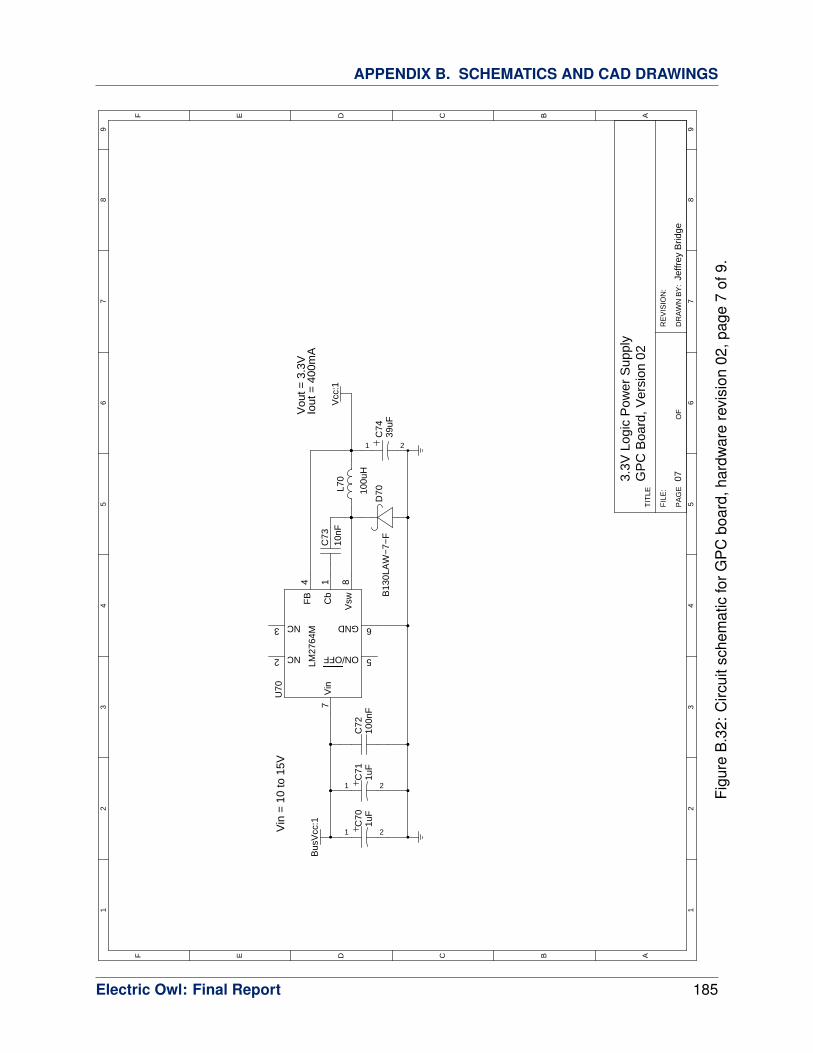
APPENDIX B. SCHEMATICS AND CAD DRAWINGS
FIL
E:
RE
VIS
ION
:
DR
AW
N B
Y:
PA
GE
OF
TIT
LEABCDEF
12
34
56
78
9
ABCDEF
12
34
56
78
9
GP
C B
oard
, Ver
sion
02
Jeffr
ey B
ridge
07
C73
10nF
C72
100n
F
1 2
C74
39uF
1 2
C70
1uF
L70
100u
H
B13
0LA
W−
7−F
D70
3.3V
Log
ic P
ower
Sup
ply
Vin
= 1
0 to
15V
Vou
t = 3
.3V
Iout
= 4
00m
A
Vcc
:1
Bus
Vcc
:1C
b1
FB
4
ON/OFF 5
Vsw
8
NC3
LM27
64M
Vin
7
GND 6
NC2
U70
1 2
C71
1uF
Figu
reB
.32:
Circ
uits
chem
atic
forG
PC
boar
d,ha
rdw
are
revi
sion
02,p
age
7of
9.
Electric Owl: Final Report 185

APPENDIX B. SCHEMATICS AND CAD DRAWINGS
FIL
E:
RE
VIS
ION
:
DR
AW
N B
Y:
PA
GE
OF
TIT
LEABCDEF
12
34
56
78
9
ABCDEF
12
34
56
78
9
GP
C B
oard
, Ver
sion
02
Rob
ert B
rock
man
II08S
eria
l Por
t Int
erfa
ce
CO
NS
OLE
_RX
:1
CO
NS
OLE
_TX
:1
2V
+
3C
1−
4C
2+
5C
2−
6V
−
7T
x2 O
ut
8R
x2 In
9R
x2 O
ut
10T
x2 In
11T
x1 In
12R
x1 O
ut13
Rx1
In
14T
x1 O
ut
1C
1+
MA
X23
2U
81
Vcc
:1
C81
0.1u
C82
0.1u
C83
0.1u
C84
0.1u
1 2
C80
10uF
21 3
CO
NS
OLE
Figu
reB
.33:
Circ
uits
chem
atic
forG
PC
boar
d,ha
rdw
are
revi
sion
02,p
age
8of
9.
Electric Owl: Final Report 186
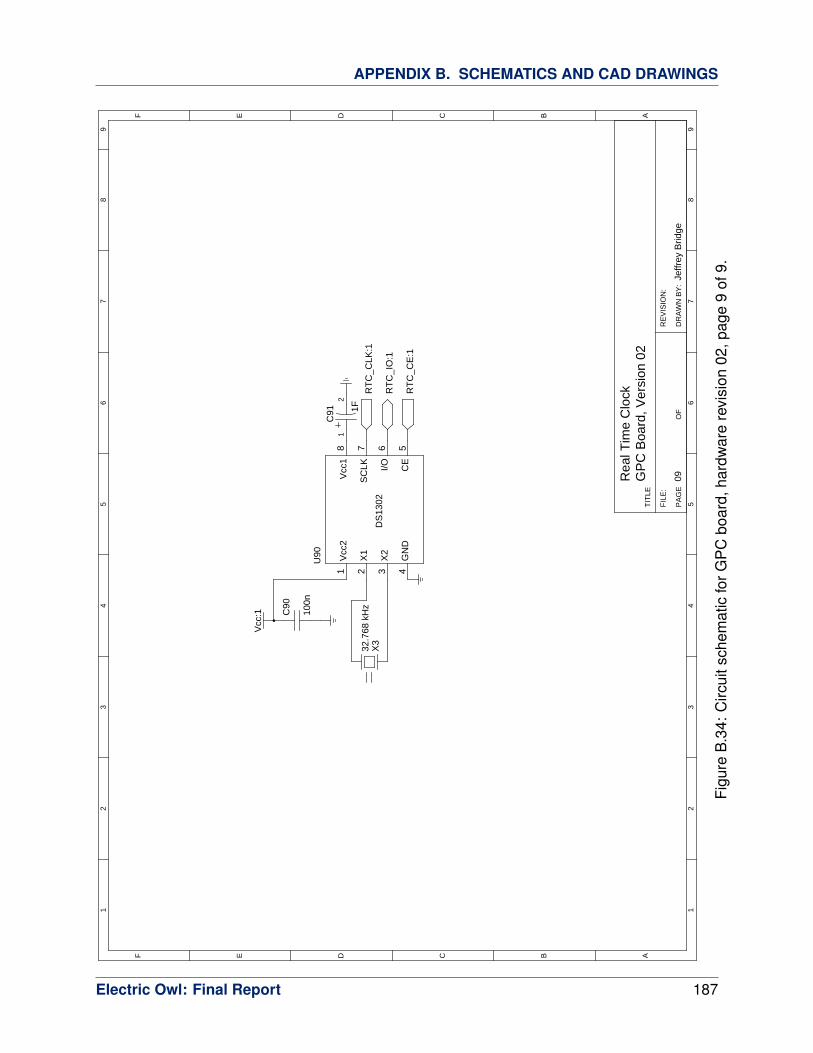
APPENDIX B. SCHEMATICS AND CAD DRAWINGS
FIL
E:
RE
VIS
ION
:
DR
AW
N B
Y:
PA
GE
OF
TIT
LEABCDEF
12
34
56
78
9
ABCDEF
12
34
56
78
9
GP
C B
oard
, Ver
sion
02
Jeffr
ey B
ridge
09Rea
l Tim
e C
lockR
TC
_CLK
:1
Vcc
:1
Vcc
18
SC
LK7
X2
3
X1
2
I/O6
GN
D4
DS
1302
Vcc
21
CE
5
U90
12
C91 1F
C90
100n
RT
C_C
E:1
RT
C_I
O:1
X3
32.7
68 k
Hz
Figu
reB
.34:
Circ
uits
chem
atic
forG
PC
boar
d,ha
rdw
are
revi
sion
02,p
age
9of
9.
Electric Owl: Final Report 187

C Assembly Instructions and Bill of Mate-
rials
C.1 Aircraft Hardware
The final prototype aircraft began as an off-the-shelf Senior Telemaster from Hobby Lobby
International, Inc. This is a large model aircraft frame with a 2 m wingspan, and is available
pre-assembled in a almost-ready-to-fly (ARF) kit.
Qty Part Mfr Description
1 Senior Telemaster Hobby Lobby ARF RC airframe kit
1 4120/18 Axi Main drive motor
5 HS-322HD Hitec RC Servomotors
1 #511 Steel Rod Sullivan Control Set, straight linkage
2 #580 Precision Rod Sullivan Control Set, carbon-fiber reinforced
2 3.25 in rubber wheels Dubro Main landing gear
1 LP 13080E APC Propellers Composite propeller 13x8E
1 AR6200 Spektrum RC receiver
1 VEN-15021 Venom Power 5000mah 22.2V Li-Po battery
1 JSP91010 JR Sports 4.8V 700mah NiCd battery
1 DX6i Spektrum 6-channel RC transmitter, 2.4 GHz
Table C.1: Bill of Materials for Test Airframe
Electric Owl: Final Report 188

APPENDIX C. ASSEMBLY INSTRUCTIONS AND BILL OF MATERIALS
C.2 Avionics Package
Once the bare circuit boards have been divided, solder paste can be placed on all of the
populated pads. This can be done either manually or by using a solder mask generated from
the layout file. The relevant parts may then be placed manually or with standard automated
fabrication tools. Care must be taken to observe the polarity of certain capacitors and active
components.
The team recommends two solder reflow passes when using manual construction. Several
of the larger inductors and capacitors take significant time to heat to the melting point, which
may cause damage to the active components, and should be installed first. The remaining
surface-mount components may be installed at once. Through-hole components, including
the bus and debugging headers, should be installed separately.
Note that on the sensors board, there are several QFN packages that have no visible leads
from the top. Extreme care must be taken with these components when soldering to avoid
solder bridges. After construction, it is advisable to check for solder bridges both visually with
the aid of a microscope, and electrically with a digital multimeter. Electrically reported shorts
should be compared with the system schematic to establish whether connectivity is expected.
Electric Owl: Final Report 189

APPENDIX C. ASSEMBLY INSTRUCTIONS AND BILL OF MATERIALS
../../../hardware/boards/backplane03/board-backplane.pcbfrontassembly, scale = 1:1.000
Figu
reC
.1:
Fron
tas
sem
bly
diag
ram
for
Bac
kpla
neR
ev03
,re
prod
uced
tosc
ale.
The
silk
scre
enin
dica
tes
the
com
pone
ntre
fere
nce
desi
gnat
ors
fort
heco
rres
pond
ing
pads
.P
arti
nfor
mat
ion
fore
ach
refe
renc
ede
sign
ator
isin
Tabl
eC
.2.
Electric Owl: Final Report 190

APPENDIX C. ASSEMBLY INSTRUCTIONS AND BILL OF MATERIALS
../../../hardware/boards/servo03/board-servo.pcb
frontassembly, scale =
1:1.000
Figure C.2: Front assembly diagram for Servo Board Rev 03, reproduced to scale. Thesilkscreen indicates the component reference designators for the corresponding pads. Partinformation for each reference designator is in Table C.3.
../../../hardware/boards/radio03/board-radio.pcb
frontassembly, scale =
1:1.000Figure C.3: Front assembly diagram for Radio Board Rev 03, reproduced to scale. Thesilkscreen indicates the component reference designators for the corresponding pads. Partinformation for each reference designator is in Table C.4.
Electric Owl: Final Report 191

APPENDIX C. ASSEMBLY INSTRUCTIONS AND BILL OF MATERIALS
../../../hardware/boards/sensors03/board-sensors.pcb
frontassembly, scale =
1:1.000
Figure C.4: Front assembly diagram for Sensors Board Rev 03, reproduced to scale. Thesilkscreen indicates the component reference designators for the corresponding pads. Partinformation for each reference designator is in Table C.5.
../../../hardware/boards/gpc02/board-gpc.pcb
frontassembly, scale =
1:1.000Figure C.5: Front assembly diagram for GPC Board Rev 02, reproduced to scale. Thesilkscreen indicates the component reference designators for the corresponding pads. Partinformation for each reference designator is in Table C.6.
Electric Owl: Final Report 192
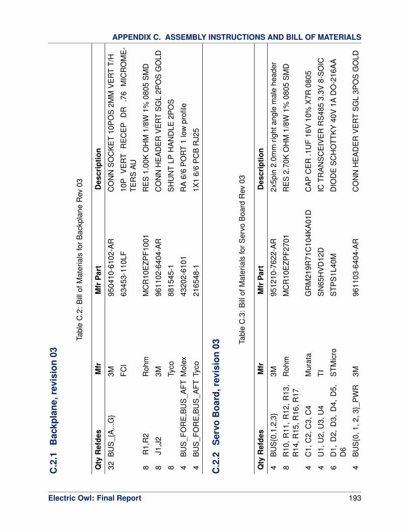
APPENDIX C. ASSEMBLY INSTRUCTIONS AND BILL OF MATERIALS
C.2
.1B
ackp
lane
,rev
isio
n03
Tabl
eC
.2:
Bill
ofM
ater
ials
forB
ackp
lane
Rev
03
Qty
Ref
des
Mfr
Mfr
Par
tD
escr
iptio
n
32B
US
_{A
...G
}3M
9504
10-6
102-
AR
CO
NN
SO
CK
ET
10P
OS
2MM
VE
RT
T/H
FCI
6345
3-11
0LF
10P
VE
RT
RE
CE
PD
R.7
6M
ICR
OM
E-
TER
SAU
8R
1,R
2R
ohm
MC
R10
EZP
F100
1R
ES
1.00
KO
HM
1/8W
1%08
05S
MD
8J1
,J2
3M96
1102
-640
4-A
RC
ON
NH
EA
DE
RV
ER
TS
GL
2PO
SG
OLD
8Ty
co88
1545
-1S
HU
NT
LPH
AN
DLE
2PO
S
4B
US
_FO
RE
,BU
S_A
FTM
olex
4320
2-61
01R
A6/
6P
OR
T1
low
profi
le
4B
US
_FO
RE
,BU
S_A
FTTy
co21
6548
-11X
16/
6P
CB
RJ2
5
C.2
.2S
ervo
Boa
rd,r
evis
ion
03 Tabl
eC
.3:
Bill
ofM
ater
ials
forS
ervo
Boa
rdR
ev03
Qty
Ref
des
Mfr
Mfr
Par
tD
escr
iptio
n
4B
US
{0,1
,2,3
}3M
9512
10-7
622-
AR
2x5p
in2.
0mm
right
angl
em
ale
head
er
8R
10,
R11
,R
12,
R13
,R
14,R
15,R
16,R
17R
ohm
MC
R10
EZP
F270
1R
ES
2.70
KO
HM
1/8W
1%08
05S
MD
4C
1,C
2,C
3,C
4M
urat
aG
RM
219R
71C
104K
A01
DC
AP
CE
R.1
UF
16V
10%
X7R
0805
4U
1,U
2,U
3,U
4TI
SN
65H
VD
12D
ICTR
AN
SC
EIV
ER
RS
485
3.3V
8-S
OIC
6D
1,D
2,D
3,D
4,D
5,D
6S
TMic
roS
TPS
1L40
MD
IOD
ES
CH
OTT
KY
40V
1AD
O-2
16A
A
4B
US
{0,1
,2,3
}_P
WR
3M96
1103
-640
4-A
RC
ON
NH
EA
DE
RV
ER
TS
GL
3PO
SG
OLD
Electric Owl: Final Report 193

APPENDIX C. ASSEMBLY INSTRUCTIONS AND BILL OF MATERIALS
Tabl
eC
.3:
Bill
ofM
ater
ials
forS
ervo
Boa
rdR
ev03
Qty
Ref
des
Mfr
Mfr
Par
tD
escr
iptio
n
4(n
one)
Tyco
8815
45-2
SH
UN
TLP
W/H
AN
DLE
2P
OS
30AU
4F0
,F1,
F2,F
3Li
ttelfu
se18
12L1
25D
RP
TC1.
25A
15V
DC
RE
SE
TTA
BLE
1812
L
1U
5A
tmel
ATxm
ega3
2A4-
AUAV
RM
CU
32K
flash
1.6V
44-T
QFP
1X
1A
brac
onA
BLS
2-7.
3728
MH
Z-D
4Y-T
CR
YS
TAL
7.37
28M
HZ
18P
FS
MD
2C
20,C
21AV
X08
055A
120J
AT2A
CA
PC
ER
M12
PF
5%50
VN
P0
0805
1P
DI
Hiro
seD
F11-
6DS
-2D
SA
(05)
CO
NN
RE
CE
PT
6PO
S2M
MP
CB
TIN
1R
20R
ohm
MC
R10
EZP
F100
2R
ES
10.0
KO
HM
1/8W
1%08
05S
MD
1L2
0TD
KM
LZ20
12E
100M
TIN
DU
CTO
RM
ULT
ILAY
ER
10U
H08
05
1L2
1La
irdLF
0805
A25
2R-1
0FE
RR
ITE
CH
IP12
67O
HM
S10
0MA
0805
6C
22,C
26,C
2A,C
2B,
C2C
,C2D
Roh
mTC
P0J
106M
8RC
AP
TAN
T10
UF
6.3V
20%
SM
D
7C
23,
C24
,C
25,
C27
,C
28,C
29,C
2EM
urat
aG
RM
219R
71C
104K
A01
DC
AP
CE
R.1
UF
16V
10%
X7R
0805
1R
1R
ohm
MC
R10
EZP
F470
0R
ES
470
OH
M1/
8W1%
0805
SM
D
1D
20S
tanl
eyE
lect
ricC
oFR
1112
H-T
RLE
DR
ED
0805
SM
D
1U
21Li
near
LTC
6652
BH
MS
8-2.
5#P
BF
ICR
EF
PR
EC
LN8-
MS
OP
1U
22Li
near
LTC
6652
BH
MS
8-2.
048#
PB
FIC
RE
FP
RE
CLN
8-M
SO
P
2R
21,R
22R
ohm
MC
R10
EZP
F100
1R
ES
1.00
KO
HM
1/8W
1%08
05S
MD
2U
30,U
31TI
TXB
0101
DB
VR
ICV
OLT
-LV
LTR
AN
SL
1BIT
SO
T23-
6
2C
30,C
31M
urat
aG
RM
219R
71C
104K
A01
DC
AP
CE
R.1
UF
16V
10%
X7R
0805
1U
32TI
CD
4017
BM
96IC
10-O
UT
DE
CA
DE
CO
UN
TER
16-S
OIC
6S
_OU
T{1,
2,3,
4,5,
6}3M
9611
03-6
404-
AR
CO
NN
HE
AD
ER
VE
RT
SG
L3P
OS
GO
LD
Electric Owl: Final Report 194

APPENDIX C. ASSEMBLY INSTRUCTIONS AND BILL OF MATERIALS
Tabl
eC
.3:
Bill
ofM
ater
ials
forS
ervo
Boa
rdR
ev03
Qty
Ref
des
Mfr
Mfr
Par
tD
escr
iptio
n
1H
V_B
ATT
Mol
ex70
543-
0003
CO
NN
HE
AD
ER
4PO
S.1
00V
ER
TG
OLD
1U
40N
atio
nal
LM26
76S
-12/
NO
PB
ICR
EG
SIM
PLE
SW
ITC
HE
RTO
-263
-7
1C
40TD
KC
5750
X7R
1H10
6MM
LCC
-SM
D/S
MT
2220
10uF
50vo
ltsX
7R20
%
1C
43K
emet
C08
05C
104K
5RA
CTU
CA
P.1
0UF
50V
CE
RA
MIC
X7R
0805
1C
44Ya
geo
CC
0805
KR
X7R
9BB
103
CA
P10
000P
F50
VC
ER
AM
ICX
7R08
05
1D
40D
iode
sIn
cP
DS
360-
13D
IOD
ES
CH
OTT
KY
3A60
VP
WR
DI5
1L4
0B
ourn
sS
RR
1210
-560
MPo
wer
Indu
ctor
s56
uH
1C
45N
ippo
nC
hem
i-Con
AP
XA
160A
RA
390M
F60G
CA
P39
UF
16V
ELE
CT
PO
LYS
MD
1R
40S
usum
uR
R12
20P
-205
1-D
-MR
ES
2.05
KO
HM
1/10
W.5
%08
05S
MD
1U
41TI
OPA
2336
UIC
OPA
MP
GP
R-R
100K
HZ
8SO
IC
1R
41P
anas
onic
EC
GE
RA
-6A
EB
105V
RE
S1M
OH
M1/
8W.1
%08
05S
MD
1R
42P
anas
onic
EC
GE
RA
-6A
EB
513V
RE
S51
KO
HM
1/8W
.1%
0805
SM
D
1C
46TD
KC
2012
X7R
1A10
5KC
AP
CE
R1.
0UF
10V
X7R
10%
0805
1U
42TI
INA
195A
IDB
VR
ICC
UR
RE
NT
MO
NIT
OR
3%S
OT2
3-5
1R
43O
hmite
LVK
12R
010F
ER
RE
S.0
1O
HM
1/2W
1%4-
TER
M12
06
3C
47,C
48,C
49M
urat
aG
RM
219R
71C
104K
A01
DC
AP
CE
R.1
UF
16V
10%
X7R
0805
1R
44R
ohm
MC
R10
EZP
F100
2R
ES
10.0
KO
HM
1/8W
1%08
05S
MD
1Q
40D
iode
s/Ze
tex
BS
S13
8TA
MO
SFE
TN
-CH
50V
200M
AS
OT2
3-3
1LV
_BAT
T3M
9611
03-6
404-
AR
CO
NN
HE
AD
ER
VE
RT
SG
L3P
OS
GO
LD
1U
52TI
INA
195A
IDB
VR
ICC
UR
RE
NT
MO
NIT
OR
3%S
OT2
3-5
1R
50O
hmite
LVK
25R
002F
ER
RE
S.0
02O
HM
2W1%
4-TE
RM
1224
Electric Owl: Final Report 195

APPENDIX C. ASSEMBLY INSTRUCTIONS AND BILL OF MATERIALS
Tabl
eC
.3:
Bill
ofM
ater
ials
forS
ervo
Boa
rdR
ev03
Qty
Ref
des
Mfr
Mfr
Par
tD
escr
iptio
n
1C
57M
urat
aG
RM
219R
71C
104K
A01
DC
AP
CE
R.1
UF
16V
10%
X7R
0805
1C
50N
ippo
nC
hem
i-Con
AP
XE
160A
RA
330M
E61
GC
AP
33U
F16
VE
LEC
TP
OLY
SM
D
1C
51M
urat
aG
RM
219R
71C
104K
A01
DC
AP
CE
R.1
UF
16V
10%
X7R
0805
1U
50N
atio
nal
LM34
78M
M/N
OP
BIC
CTR
LRS
WR
EG
N-C
H8M
SO
P
1C
52Ya
geo
CC
0805
KR
X7R
9BB
332
CA
P33
00P
F50
VC
ER
AM
ICX
7R08
05
1C
53M
urat
aG
RM
188R
71E
683K
A01
DC
AP
CE
R68
000P
F25
V10
%X
7R06
03
1R
51S
usum
uR
R12
20P
-751
-DR
ES
750
OH
M1/
10W
.5%
0805
SM
D
1R
52R
ohm
MC
R10
EZH
F301
2R
ES
30.1
KO
HM
1/8W
1%08
05S
MD
1R
53S
usum
uR
R12
20P
-751
-DR
ES
750
OH
M1/
10W
.5%
0805
SM
D
1C
54Ya
geo
CC
0805
KR
X7R
9BB
103
CA
P10
000P
F50
VC
ER
AM
ICX
7R08
05
1R
54S
tack
pole
CS
R1/
20.
015
1%I
RE
S0.
015
OH
M1/
2W1%
1206
SM
D
1L5
0P
ulse
P11
67.2
72N
LTIN
DU
CTO
RP
WR
SH
IELD
ED
1.8U
HS
MD
1Q
50Fa
irchi
ldFD
S66
90A
_QM
OS
FETs
SO
-8S
GL
N-C
H30
V
1D
50D
iode
sIn
cB
530C
-13-
FD
IOD
ES
CH
OTT
KY
30V
5AS
MC
1C
55TD
KC
4532
X7R
1E22
6MM
LCC
-SM
D/S
MT
1812
22uF
25vo
lts
1R
55R
ohm
MC
R10
EZP
F100
1R
ES
1.00
KO
HM
1/8W
1%08
05S
MD
1R
56R
ohm
MC
R10
EZP
F845
1R
ES
8.45
KO
HM
1/8W
1%08
05S
MD
1R
57P
anas
onic
EC
GE
RA
-6A
EB
184V
RE
S18
0KO
HM
1/8W
.1%
0805
SM
D
1R
58P
anas
onic
EC
GE
RA
-6A
EB
363V
RE
S36
KO
HM
1/8W
.1%
0805
SM
D
1C
56TD
KC
2012
X7R
1A10
5KC
AP
CE
R1.
0UF
10V
X7R
10%
0805
1U
60N
atio
nal
LM22
676T
JE-5
.0/N
OP
BIC
RE
GS
WIT
CH
BU
CK
3A5V
TO26
3-7
1C
60TD
KC
3225
X7R
1E10
6MC
AP
CE
R10
UF
25V
X7R
20%
1210
Electric Owl: Final Report 196

APPENDIX C. ASSEMBLY INSTRUCTIONS AND BILL OF MATERIALS
Tabl
eC
.3:
Bill
ofM
ater
ials
forS
ervo
Boa
rdR
ev03
Qty
Ref
des
Mfr
Mfr
Par
tD
escr
iptio
n
1C
61Ta
iyo
Yude
nTM
K21
2BJ1
05K
G-T
CA
PC
ER
1.0U
F25
VX
5R08
05
1C
62K
emet
C08
05C
103K
5RA
CTU
CA
P10
000P
F50
VC
ER
AM
ICX
7R08
05
1D
60V
isha
yS
L43-
E3/
57T
DIO
DE
SC
HO
TTK
Y4A
30V
SM
C
1L6
0B
ourn
sS
RR
1260
-150
MIN
DU
CTO
RP
OW
ER
15U
H5.
0AS
MD
1C
63N
ippo
nC
hem
i-Con
AP
XC
100A
RA
560M
E60
GC
AP
56U
F10
VE
LEC
TP
OLY
SM
D
1U
70N
atio
nal
LM26
74M
-3.3
ICR
EG
SW
3.3V
500M
AS
TPD
N8S
OIC
2C
70,C
71K
emet
C12
06C
105K
3RA
CTU
CA
P1.
0UF
25V
CE
RA
MIC
X7R
1206
1C
72AV
X08
053C
104K
AT2A
CA
PC
ER
M.1
0UF
10%
25V
X7R
0805
1C
73Ya
geo
CC
0805
KR
X7R
9BB
103
CA
P10
000P
F50
VC
ER
AM
ICX
7R08
05
1D
70D
iode
sIn
cB
130L
AW-7
-FD
IOD
ES
CH
OTT
KY
1A30
VS
OD
123
1L7
0C
oiltr
onic
sD
R74
-101
-RIN
DU
CTO
RS
HIE
LDP
WR
100U
HS
MD
1C
74N
ippo
nC
hem
i-Con
AP
XA
160A
RA
390M
F60G
CA
P39
UF
16V
ELE
CT
PO
LYS
MD
6S
_IN
{1,2
,3,4
,5,6
}JR
serv
oex
tens
ion
cabl
e12
"m
ale-
fem
ale
6R
80,
R82
,R
84,
R86
,R
88,R
8AR
ohm
MC
R10
EZP
F100
2R
ES
10.0
KO
HM
1/8W
1%08
05S
MD
6R
81,
R83
,R
85,
R87
,R
89,R
8BR
ohm
MC
R10
EZP
F200
2R
ES
20.0
KO
HM
1/8W
1%08
05S
MD
Electric Owl: Final Report 197

APPENDIX C. ASSEMBLY INSTRUCTIONS AND BILL OF MATERIALS
C.2
.3R
adio
Boa
rd,r
evis
ion
03 Tabl
eC
.4:
Bill
ofM
ater
ials
forR
adio
Boa
rdR
ev03
Qty
Ref
des
Mfr
Mfr
Par
tD
escr
iptio
n
4B
US
{0,1
,2,3
}3M
9512
10-7
622-
AR
2x5p
in2.
0mm
right
angl
em
ale
head
er
4C
1,C
2,C
3,C
4M
urat
aG
RM
219R
71C
104K
A01
DC
AP
CE
R.1
UF
16V
10%
X7R
0805
4U
1,U
2,U
3,U
4TI
SN
65H
VD
12D
ICTR
AN
SC
EIV
ER
RS
485
3.3V
8-S
OIC
4D
1,D
2,D
3,D
4S
TMic
roS
TPS
1L40
MD
IOD
ES
CH
OTT
KY
40V
1AD
O-2
16A
A
1U
5A
tmel
ATxm
ega3
2A4-
AUAV
RM
CU
32K
flash
1.6V
44-T
QFP
1X
1A
brac
onA
BLS
2-7.
3728
MH
Z-D
4Y-T
CR
YS
TAL
7.37
28M
HZ
18P
FS
MD
2C
20,C
21AV
X08
055A
120J
AT2A
CA
PC
ER
M12
PF
5%50
VN
P0
0805
1P
DI
Hiro
seD
F11-
6DS
-2D
SA
(05)
CO
NN
RE
CE
PT
6PO
S2M
MP
CB
TIN
1R
20R
ohm
MC
R10
EZP
F100
2R
ES
10.0
KO
HM
1/8W
1%08
05S
MD
1L2
0TD
KM
LZ20
12E
100M
TIN
DU
CTO
RM
ULT
ILAY
ER
10U
H08
05
1L2
1La
irdLF
0805
A25
2R-1
0FE
RR
ITE
CH
IP12
67O
HM
S10
0MA
0805
2C
22,C
26R
ohm
TCP
0J10
6M8R
CA
PTA
NT
10U
F6.
3V20
%S
MD
8C
23,
C24
,C
25,
C27
,C
2A,C
2B,C
2C,C
2DM
urat
aG
RM
219R
71C
104K
A01
DC
AP
CE
R.1
UF
16V
10%
X7R
0805
1R
1R
ohm
MC
R10
EZP
F470
0R
ES
470
OH
M1/
8W1%
0805
SM
D
1D
20S
tanl
eyE
lect
ricC
oFR
1112
H-T
RLE
DR
ED
0805
SM
D
4R
21,R
23,R
25,R
27R
ohm
MC
R10
EZP
F680
1R
ES
6.80
KO
HM
1/8W
1%08
05S
MD
4R
22,R
24,R
26,R
28R
ohm
MC
R10
EZP
F100
3R
ES
100K
OH
M1/
8W1%
0805
SM
D
1U
30D
igi
XTe
nd90
0-O
EM
XTe
nd90
01W
RP
SM
A-4
0M
ileR
ange
1U
31TI
TXB
0101
DB
VR
ICV
OLT
-LV
LTR
AN
SL
1BIT
SO
T23-
6
2C
30,C
31M
urat
aG
RM
219R
71C
104K
A01
DC
AP
CE
R.1
UF
16V
10%
X7R
0805
Electric Owl: Final Report 198

APPENDIX C. ASSEMBLY INSTRUCTIONS AND BILL OF MATERIALS
Tabl
eC
.4:
Bill
ofM
ater
ials
forR
adio
Boa
rdR
ev03
Qty
Ref
des
Mfr
Mfr
Par
tD
escr
iptio
n
4R
31,R
33,R
35,R
37R
ohm
MC
R10
EZP
F100
2R
ES
10.0
KO
HM
1/8W
1%08
05S
MD
4R
30,R
32,R
34,R
36R
ohm
MC
R10
EZP
F200
2R
ES
20.0
KO
HM
1/8W
1%08
05S
MD
1U
60N
atio
nal
LM22
675M
RE
-5.0
/NO
PB
ICR
EG
SW
ITC
HB
UC
K1A
5V8P
SO
P
2C
60,C
61K
emet
C12
06C
105K
3RA
CTU
CA
P1.
0UF
25V
CE
RA
MIC
X7R
1206
1C
62Ta
iyo
Yude
nTM
K21
2BJ1
05K
G-T
CA
PC
ER
1.0U
F25
VX
5R08
05
1C
63K
emet
C08
05C
103K
5RA
CTU
CA
P10
000P
F50
VC
ER
AM
ICX
7R08
05
1D
60D
iode
sIn
cB
30LA
W-7
-FD
IOD
ES
CH
OTT
KY
1A30
VS
OD
123
1L6
0W
urth
7447
7111
8IN
DU
CTO
RP
OW
ER
18U
H3.
48A
SM
D
1C
64N
ippo
nC
hem
i-Con
AP
XC
100A
RA
560M
E60
GC
AP
56U
F10
VE
LEC
TP
OLY
SM
D
1U
70N
atio
nal
LM26
74M
-3.3
ICR
EG
SW
3.3V
500M
AS
TPD
N8S
OIC
2C
70,C
71K
emet
C12
06C
105K
3RA
CTU
CA
P1.
0UF
25V
CE
RA
MIC
X7R
1206
1C
72AV
X08
053C
104K
AT2A
CA
PC
ER
M.1
0UF
10%
25V
X7R
0805
1C
73Ya
geo
CC
0805
KR
X7R
9BB
103
CA
P10
000P
F50
VC
ER
AM
ICX
7R08
05
1D
70D
iode
sIn
cB
130L
AW-7
-FD
IOD
ES
CH
OTT
KY
1A30
VS
OD
123
1L7
0C
oiltr
onic
sD
R74
-101
-RIN
DU
CTO
RS
HIE
LDP
WR
100U
HS
MD
1C
74N
ippo
nC
hem
i-Con
AP
XA
160A
RA
390M
F60G
CA
P39
UF
16V
ELE
CT
PO
LYS
MD
Electric Owl: Final Report 199

APPENDIX C. ASSEMBLY INSTRUCTIONS AND BILL OF MATERIALS
C.2
.4S
enso
rsB
oard
,rev
isio
n03
Tabl
eC
.5:
Bill
ofM
ater
ials
forS
enso
rsB
oard
Rev
03
Qty
Ref
des
Mfr
Mfr
Par
tD
escr
iptio
n
4B
US
0,B
US
1,B
US
2,B
US
33M
9512
10-7
622-
AR
2x5p
in2.
0mm
right
angl
em
ale
head
er
4C
1,C
2,C
3,C
4M
urat
aG
RM
219R
71C
104K
A01
DC
AP
CE
R.1
UF
16V
10%
X7R
0805
4U
1,U
2,U
3,U
4TI
SN
65H
VD
12D
ICTR
AN
SC
EIV
ER
RS
485
3.3V
8-S
OIC
4D
1,D
2,D
3,D
4S
TMic
roS
TPS
1L40
MD
IOD
ES
CH
OTT
KY
40V
1AD
O-2
16A
A
1U
5A
tmel
ATxm
ega3
2A4-
AUAV
RM
CU
32K
flash
1.6V
44-T
QFP
1X
1A
brac
onA
BLS
2-7.
3728
MH
Z-D
4Y-T
CR
YS
TAL
7.37
28M
HZ
18P
FS
MD
2C
20,C
21AV
X08
055A
120J
AT2A
CA
PC
ER
M12
PF
5%50
VN
P0
0805
1P
DI
Hiro
seD
F11-
6DS
-2D
SA
(05)
CO
NN
RE
CE
PT
6PO
S2M
MP
CB
TIN
3R
20,R
21,R
22R
ohm
MC
R10
EZP
F100
2R
ES
10.0
KO
HM
1/8W
1%08
05S
MD
1L2
0TD
KM
LZ20
12E
100M
TIN
DU
CTO
RM
ULT
ILAY
ER
10U
H08
05
1L2
1La
irdLF
0805
A25
2R-1
0FE
RR
ITE
CH
IP12
67O
HM
S10
0MA
0805
3C
22,C
26,C
29R
ohm
TCP
0J10
6M8R
CA
PTA
NT
10U
F6.
3V20
%S
MD
6C
23,
C24
,C
25,
C27
,C
28,C
2AM
urat
aG
RM
219R
71C
104K
A01
DC
AP
CE
R.1
UF
16V
10%
X7R
0805
1R
1R
ohm
MC
R10
EZP
F470
0R
ES
470
OH
M1/
8W1%
0805
SM
D
1D
20S
tanl
eyE
lect
ricC
oFR
1112
H-T
RLE
DR
ED
0805
SM
D
1U
21Li
near
LTC
6652
BH
MS
8-2.
5#P
BF
ICR
EF
PR
EC
LN8-
MS
OP
1Fr
eesc
ale
MP
XM
2102
AS
SE
NS
PR
ES
SU
RE
14.5
PS
IMA
XM
PAK
1U
30B
osch
BM
P08
5D
IGIT
AL
BA
RO
ME
TRIC
PR
ES
SU
RE
SN
SR
Electric Owl: Final Report 200

APPENDIX C. ASSEMBLY INSTRUCTIONS AND BILL OF MATERIALS
Tabl
eC
.5:
Bill
ofM
ater
ials
forS
enso
rsB
oard
Rev
03
Qty
Ref
des
Mfr
Mfr
Par
tD
escr
iptio
n
2C
30,C
34R
ohm
TCP
0J10
6M8R
CA
PTA
NT
10U
F6.
3V20
%S
MD
5C
31,
C32
,C
33,
C35
,C
37M
urat
aG
RM
219R
71C
104K
A01
DC
AP
CE
R.1
UF
16V
10%
X7R
0805
1U
31Fr
eesc
ale
MP
XV
7002
DP
Boa
rdM
ount
Pre
ssur
eS
enso
rsS
OP
DU
AL
2KPA
1L3
0TD
KM
LZ20
12E
100M
TIN
DU
CTO
RM
ULT
ILAY
ER
10U
H08
05
1U
32TI
OPA
335A
ID0.
05uV
/Cm
ax,S
ingl
e-S
uppl
yC
MO
SO
per-
atio
nalA
mpl
ifier
1R
33R
ohm
MC
R10
EZP
F100
2R
ES
10.0
KO
HM
1/8W
1%08
05S
MD
2R
30,R
31R
ohm
MC
R10
EZP
F200
2R
ES
20.0
KO
HM
1/8W
1%08
05S
MD
1R
32R
ohm
MC
R10
EZP
F270
2R
ES
27.0
KO
HM
1/8W
1%08
05S
MD
1C
36M
urat
aG
RM
21B
R71
E15
4KA
01L
CA
PC
ER
.15U
F25
V10
%X
7R08
05
2C
41,C
44R
ohm
TCP
0J10
6M8R
CA
PTA
NT
10U
F6.
3V20
%S
MD
2C
40,C
43M
urat
aG
RM
219R
71C
104K
A01
DC
AP
CE
R.1
UF
16V
10%
X7R
0805
1U
40S
TMic
roel
ectro
nics
LPR
530A
LG
YR
OS
CO
PE
ME
MS
DU
AL
AX
IS16
-LG
A
3R
41,R
42,R
44R
ohm
MC
R10
EZP
F330
2R
ES
33.0
KO
HM
1/8W
1%08
05S
MD
3C
42,C
4C,C
45AV
X08
055C
124K
AT2A
CA
PC
ER
M.1
2UF
10%
50V
X7R
0805
2R
40,R
43R
ohm
MC
R10
EZP
F100
2R
ES
10.0
KO
HM
1/8W
1%08
05S
MD
2C
4A,C
4DYa
geo
CC
0805
KR
X7R
9BB
103
CA
P10
000P
F50
VC
ER
AM
ICX
7R08
05
2C
4B,C
4ETa
iyo
Yude
nE
MK
212B
7474
KD
-TC
AP
CE
R.4
7UF
16V
X7R
0805
1U
41S
TMic
roel
ectro
nics
LY53
0ALH
GY
RO
SC
OP
EM
EM
SS
GL
AX
IS16
-LG
A
1U
50A
nalo
gD
evic
esA
DX
L335
Trip
leA
xis
Acc
eler
omet
er+-
3G
Electric Owl: Final Report 201

APPENDIX C. ASSEMBLY INSTRUCTIONS AND BILL OF MATERIALS
Tabl
eC
.5:
Bill
ofM
ater
ials
forS
enso
rsB
oard
Rev
03
Qty
Ref
des
Mfr
Mfr
Par
tD
escr
iptio
n
1U
51TI
OPA
4330
AID
R1.
8V,
35Â
tA,
mic
roPo
wer
,P
reci
sion
,Ze
roD
riftC
MO
SO
pA
mp
1C
51R
ohm
TCP
0J10
6M8R
CA
PTA
NT
10U
F6.
3V20
%S
MD
2C
50,C
52M
urat
aG
RM
219R
71C
104K
A01
DC
AP
CE
R.1
UF
16V
10%
X7R
0805
1R
50R
ohm
MC
R10
EZP
F150
2R
ES
15.0
KO
HM
1/8W
1%08
05S
MD
1R
51R
ohm
MC
R10
EZP
F100
2R
ES
10.0
KO
HM
1/8W
1%08
05S
MD
6R
52,
R53
,R
54,
R55
,R
56,R
57R
ohm
MC
R10
EZP
F200
2R
ES
20.0
KO
HM
1/8W
1%08
05S
MD
3C
53,C
54,C
55M
urat
aG
RM
21B
R71
E15
4KA
01L
CA
PC
ER
.15U
F25
V10
%X
7R08
05
1U
60N
atio
nal
LM22
675M
R-5
.0/N
OP
BIC
RE
GS
WIT
CH
BU
CK
1A5V
8PS
OP
1C
60K
emet
C12
06C
105K
3RA
CTU
CA
P1.
0UF
25V
CE
RA
MIC
X7R
1206
1C
62Ta
iyo
Yude
nTM
K21
2BJ1
05K
G-T
CA
PC
ER
1.0U
F25
VX
5R08
05
1C
63Ya
geo
CC
0805
KR
X7R
9BB
103
CA
P10
000P
F50
VC
ER
AM
ICX
7R08
05
1D
60D
iode
sIn
cB
30LA
W-7
-FD
IOD
ES
CH
OTT
KY
1A30
VS
OD
123
1L6
0P
ulse
P11
67.1
54N
LTIN
DU
CTO
RP
WR
SH
IELD
ED
113U
HS
MD
1C
64P
anas
onic
EC
GE
EE
-FK
1E33
0PC
AP
ELE
CT
33U
F25
VFK
SM
D
1U
70N
atio
nal
LM26
74M
-3.3
ICR
EG
SW
3.3V
500M
AS
TPD
N8S
OIC
2C
70,C
71K
emet
C12
06C
105K
3RA
CTU
CA
P1.
0UF
25V
CE
RA
MIC
X7R
1206
1C
72AV
X08
053C
104K
AT2A
CA
PC
ER
M.1
0UF
10%
25V
X7R
0805
1C
73Ya
geo
CC
0805
KR
X7R
9BB
103
CA
P10
000P
F50
VC
ER
AM
ICX
7R08
05
1D
70D
iode
sIn
cB
130L
AW-7
-FD
IOD
ES
CH
OTT
KY
1A30
VS
OD
123
1L7
0C
oiltr
onic
sD
R74
-101
-RIN
DU
CTO
RS
HIE
LDP
WR
100U
HS
MD
1C
74N
ippo
nC
hem
i-Con
AP
XA
160A
RA
390M
F60G
CA
P39
UF
16V
ELE
CT
PO
LYS
MD
Electric Owl: Final Report 202

APPENDIX C. ASSEMBLY INSTRUCTIONS AND BILL OF MATERIALS
Tabl
eC
.5:
Bill
ofM
ater
ials
forS
enso
rsB
oard
Rev
03
Qty
Ref
des
Mfr
Mfr
Par
tD
escr
iptio
n
1U
80H
oney
wel
lH
MC
5843
SE
NS
OR
MA
GN
ETI
C3
AX
IS20
-LC
C
1C
81TD
KC
3225
X7R
1E10
6MC
AP
CE
R10
UF
25V
X7R
20%
1210
1C
82Ta
iyo
Yude
nU
MK
212B
7224
KG
-TC
AP
CE
R.2
2UF
50V
X7R
0805
1of
fboa
rdG
arm
inG
PS
18x
LVC
Sen
sitiv
eW
AA
SG
PS
rece
iver
PP
Spu
ck
1G
PS
_CO
NN
JST
SM
06B
-SR
SS
-TB
(LF)
(SN
)C
ON
NH
EA
DE
RS
H6P
OS
SID
E1M
MTI
N
1U
81TI
MA
X32
32E
IDR
ICR
S32
32LI
NE
DV
R/R
CV
R16
-SO
IC
5C
83,
C86
,C
87,
C88
,C
89M
urat
aG
RM
219R
71C
104K
A01
DC
AP
CE
R.1
UF
16V
10%
X7R
0805
2C
84,C
85R
ohm
TCP
0J10
6M8R
CA
PTA
NT
10U
F6.
3V20
%S
MD
1M
OT_
DAT
_CO
NN
JST
S3B
-ZR
(LF)
(SN
)C
ON
NH
EA
DE
RZH
SID
E3P
OS
1.5M
M
1S
ON
AR
_CO
NN
JST
S3B
-ZR
(LF)
(SN
)C
ON
NH
EA
DE
RZH
SID
E3P
OS
1.5M
M
2R
81,R
83R
ohm
MC
R10
EZP
F100
2R
ES
10.0
KO
HM
1/8W
1%08
05S
MD
2R
82,R
84R
ohm
MC
R10
EZP
F200
2R
ES
20.0
KO
HM
1/8W
1%08
05S
MD
Electric Owl: Final Report 203

APPENDIX C. ASSEMBLY INSTRUCTIONS AND BILL OF MATERIALS
C.2
.5G
PC
Boa
rd,r
evis
ion
02
Tabl
eC
.6:
Bill
ofM
ater
ials
forG
PC
Boa
rdR
ev02
Qty
Ref
des
Mfr
Mfr
Par
tD
escr
iptio
n
4B
US
0,B
US
1,B
US
2,B
US
33M
9512
10-7
622-
AR
2x5p
in2.
0mm
right
angl
em
ale
head
er
4C
1,C
2,C
3,C
4M
urat
aG
RM
219R
71C
104K
A01
DC
AP
CE
R.1
UF
16V
10%
X7R
0805
4U
1,U
2,U
3,U
4TI
SN
65H
VD
12D
ICTR
AN
SC
EIV
ER
RS
485
3.3V
8-S
OIC
4D
1,D
2,D
3,D
4S
TMic
roS
TPS
1L40
MD
IOD
ES
CH
OTT
KY
40V
1AD
O-2
16A
A
1U
5A
tmel
ATxm
ega3
2A4-
AUAV
RM
CU
32K
flash
1.6V
44-T
QFP
1X
1A
brac
onA
BLS
2-7.
3728
MH
Z-D
4Y-T
CR
YS
TAL
7.37
28M
HZ
18P
FS
MD
2C
20,C
21AV
X08
055A
120J
AT2A
CA
PC
ER
M12
PF
5%50
VN
P0
0805
1P
DI
Hiro
seD
F11-
6DS
-2D
SA
(05)
CO
NN
RE
CE
PT
6PO
S2M
MP
CB
TIN
1R
20R
ohm
MC
R10
EZP
F100
2R
ES
10.0
KO
HM
1/8W
1%08
05S
MD
1L2
0TD
KM
LZ20
12E
100M
TIN
DU
CTO
RM
ULT
ILAY
ER
10U
H08
05
1L2
1La
irdLF
0805
A25
2R-1
0FE
RR
ITE
CH
IP12
67O
HM
S10
0MA
0805
2C
22,C
26R
ohm
TCP
0J10
6M8R
CA
PTA
NT
10U
F6.
3V20
%S
MD
4C
23,C
24,C
25,C
27M
urat
aG
RM
219R
71C
104K
A01
DC
AP
CE
R.1
UF
16V
10%
X7R
0805
1R
1R
ohm
MC
R10
EZP
F470
0R
ES
470
OH
M1/
8W1%
0805
SM
D
1D
20S
tanl
eyE
lect
ricC
oFR
1112
H-T
RLE
DR
ED
0805
SM
D
6R
21,
R22
,R
23,
R24
,R
25,R
26S
tack
pole
RM
CF
1/16
0R
RE
S0.
0O
HM
1/10
W06
03S
MD
1U
30A
tmel
AT91
SA
M7S
256-
AU-0
01IC
AR
M7
MC
U32
BIT
256K
64LQ
FP
2C
3B,C
3CR
ohm
TCP
0J10
6M8R
CA
PTA
NT
10U
F6.
3V20
%S
MD
Electric Owl: Final Report 204

APPENDIX C. ASSEMBLY INSTRUCTIONS AND BILL OF MATERIALS
Tabl
eC
.6:
Bill
ofM
ater
ials
forG
PC
Boa
rdR
ev02
Qty
Ref
des
Mfr
Mfr
Par
tD
escr
iptio
n
7C
30,
C31
,C
32,
C33
,C
34,C
35,C
36AV
XC
orpo
ratio
n06
03Y
C10
4KAT
2AC
AP
CE
RM
.1U
F10
%16
VX
7R06
03
1X
2A
brac
onA
BM
8G-1
8.43
2MH
Z-18
-D
2Y-T
CR
YS
TAL
18.4
32M
HZ
18P
FS
MD
2C
38,C
39FI
XM
E
1R
39R
ohm
MC
R10
EZP
F150
1R
ES
1.50
KO
HM
1/8W
1%08
05S
MD
1C
3DP
anas
onic
-EC
GP
CC
102B
NC
T-N
DC
AP
1000
PF
50V
CE
RM
CH
IP08
05
1C
3EM
urat
aG
RM
216R
71H
103K
A01
DC
AP
CE
R10
000P
F50
V10
%X
7R08
05
1R
33R
ohm
MC
R10
EZP
F470
0R
ES
470
OH
M1/
8W1%
0805
SM
D
1D
30S
tanl
eyE
lect
ricC
oP
Y11
12H
-TR
LED
YE
LLO
W-G
RE
EN
0805
SM
D
1U
31M
icro
chip
MC
P13
0T-3
00I/T
TIC
SU
PE
RV
ISO
R3.
00V
LOW
SO
T23
1R
38R
ohm
MC
R10
EZP
F100
2R
ES
10.0
KO
HM
1/8W
1%08
05S
MD
1C
3AFI
XM
E
5R
30,
R31
,R
32,
R34
,R
35R
ohm
MC
R10
EZP
F470
2R
ES
47.0
KO
HM
1/8W
1%08
05S
MD
2R
36,R
37S
tack
pole
RM
CF
1/16
0R
RE
S0.
0O
HM
1/10
W06
03S
MD
1JT
AG
Sul
lins
SB
H11
-PB
PC
-D10
-ST-
BK
CO
NN
HE
AD
ER
2.54
MM
20P
OS
GO
LD
2JT
AG
_DIS
AB
LE,T
ST
3M96
1103
-640
4-A
RC
ON
NH
EA
DE
RV
ER
TS
GL
3PO
SG
OLD
2(n
one)
Tyco
8815
45-2
SH
UN
TLP
W/H
AN
DLE
2P
OS
30AU
1U
SB
Mill
-Max
897-
43-0
05-0
0-10
0001
CO
NN
RE
CE
PT
MIN
I-US
BTY
PE
BS
MT
2R
41,R
4CR
ohm
MC
R10
EZP
F100
0R
ES
100
OH
M1/
8W1%
0805
SM
D
3R
42,R
4B,R
45R
ohm
MC
R10
EZP
F470
2R
ES
47.0
KO
HM
1/8W
1%08
05S
MD
1R
44R
ohm
MC
R10
EZP
F270
2R
ES
27.0
KO
HM
1/8W
1%08
05S
MD
Electric Owl: Final Report 205
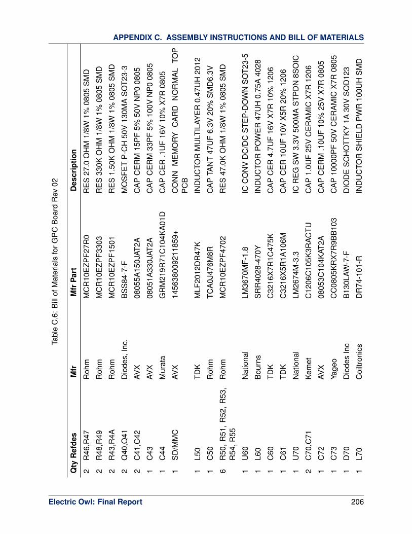
APPENDIX C. ASSEMBLY INSTRUCTIONS AND BILL OF MATERIALS
Tabl
eC
.6:
Bill
ofM
ater
ials
forG
PC
Boa
rdR
ev02
Qty
Ref
des
Mfr
Mfr
Par
tD
escr
iptio
n
2R
46,R
47R
ohm
MC
R10
EZP
F27R
0R
ES
27.0
OH
M1/
8W1%
0805
SM
D
2R
48,R
49R
ohm
MC
R10
EZP
F330
3R
ES
330K
OH
M1/
8W1%
0805
SM
D
2R
43,R
4AR
ohm
MC
R10
EZP
F150
1R
ES
1.50
KO
HM
1/8W
1%08
05S
MD
2Q
40,Q
41D
iode
s,In
c.B
SS
84-7
-FM
OS
FET
P-C
H50
V13
0MA
SO
T23-
3
2C
41,C
42AV
X08
055A
150J
AT2A
CA
PC
ER
M15
PF
5%50
VN
P0
0805
1C
43AV
X08
051A
330J
AT2A
CA
PC
ER
M33
PF
5%10
0VN
P0
0805
1C
44M
urat
aG
RM
219R
71C
104K
A01
DC
AP
CE
R.1
UF
16V
10%
X7R
0805
1S
D/M
MC
AVX
1456
3800
9211
859+
CO
NN
ME
MO
RY
CA
RD
NO
RM
AL
TOP
PC
B
1L5
0TD
KM
LF20
12D
R47
KIN
DU
CTO
RM
ULT
ILAY
ER
0.47
UH
2012
1C
50R
ohm
TCA
0J47
6M8R
CA
PTA
NT
47U
F6.
3V20
%S
MD
6.3V
6R
50,
R51
,R
52,
R53
,R
54,R
55R
ohm
MC
R10
EZP
F470
2R
ES
47.0
KO
HM
1/8W
1%08
05S
MD
1U
60N
atio
nal
LM36
70M
F-1.
8IC
CO
NV
DC
/DC
STE
P-D
OW
NS
OT2
3-5
1L6
0B
ourn
sS
RR
4028
-470
YIN
DU
CTO
RP
OW
ER
47U
H0.
75A
4028
1C
60TD
KC
3216
X7R
1C47
5KC
AP
CE
R4.
7UF
16V
X7R
10%
1206
1C
61TD
KC
3216
X5R
1A10
6MC
AP
CE
R10
UF
10V
X5R
20%
1206
1U
70N
atio
nal
LM26
74M
-3.3
ICR
EG
SW
3.3V
500M
AS
TPD
N8S
OIC
2C
70,C
71K
emet
C12
06C
105K
3RA
CTU
CA
P1.
0UF
25V
CE
RA
MIC
X7R
1206
1C
72AV
X08
053C
104K
AT2A
CA
PC
ER
M.1
0UF
10%
25V
X7R
0805
1C
73Ya
geo
CC
0805
KR
X7R
9BB
103
CA
P10
000P
F50
VC
ER
AM
ICX
7R08
05
1D
70D
iode
sIn
cB
130L
AW-7
-FD
IOD
ES
CH
OTT
KY
1A30
VS
OD
123
1L7
0C
oiltr
onic
sD
R74
-101
-RIN
DU
CTO
RS
HIE
LDP
WR
100U
HS
MD
Electric Owl: Final Report 206

APPENDIX C. ASSEMBLY INSTRUCTIONS AND BILL OF MATERIALS
Tabl
eC
.6:
Bill
ofM
ater
ials
forG
PC
Boa
rdR
ev02
Qty
Ref
des
Mfr
Mfr
Par
tD
escr
iptio
n
1C
74N
ippo
nC
hem
i-Con
AP
XA
160A
RA
390M
F60G
CA
P39
UF
16V
ELE
CT
PO
LYS
MD
1C
ON
SO
LEH
irose
DF3
-3P
-2D
S(0
1)C
ON
NH
EA
DE
R3P
OS
2MM
R/A
GO
LD
1U
81TI
MA
X32
32E
IDR
ICR
S32
32LI
NE
DV
R/R
CV
R16
-SO
IC
1C
80R
ohm
TCP
0J10
6M8R
CA
PTA
NT
10U
F6.
3V20
%S
MD
4C
81,C
82,C
83,C
84M
urat
aG
RM
219R
71C
104K
A01
DC
AP
CE
R.1
UF
16V
10%
X7R
0805
1U
90M
axim
DS
1302
ZN+
ICTI
ME
KE
EP
ER
T-C
HA
RG
EIN
D8S
OIC
1C
90M
urat
aG
RM
219R
71C
104K
A01
DC
AP
CE
R.1
UF
16V
10%
X7R
0805
1X
3A
brac
onA
BS
25-3
2.76
8KH
Z-6-
1-T
CR
YS
TAL
32.7
68K
HZ
6.0
PF
SM
D
1C
91E
lna
Am
eric
aD
B-5
R5D
105T
CA
PD
OU
BLE
LAY
ER
1.0F
5.5V
RA
D
Electric Owl: Final Report 207

APPENDIX C. ASSEMBLY INSTRUCTIONS AND BILL OF MATERIALS
C.3 Additional Tools
C.3.1 Airframe Construction
Although the Senior Telemaster kit comes largely pre-built, some essential tools are still
needed for final assembly and for modifications needed to mount the avionics. All of these
tools can be obtained from any reputable hobby store selling R/C aircraft.
Attachment of balsa and plywood components requires gap-filling cyanoacrylate glue in
most cases. Attaching the tail assembly should be done with 5-minute epoxy. A set of X-acto
knives is needed for removing damaged covering material and cutting balsa. A hacksaw is
sufficient for cutting thick balsa and plywood, in combination with coarse-grained sandpaper to
remove unevenness. Most of the additional wood needed for modifying the airframe consists
of pieces fashioned from simple half-inch square balsa sticks.
As minor damage to the airframe is inevitable, the material covering it will need to be
patched. This requires a supply of Mylar covering, ideally Super Monokote from TopFlite.
A monokote sealing iron will also be needed. Scissors are necessary for cutting pieces of
Monokote
Installing new pushrods will require strong wire cutters. Small and medium screwdrivers of
both Phillips and flathead variety, as well as a complete hex wrench set, are used for a variety
of tasks.
A specialized prop-boring tool is necessary for modifying propellers to fit on the drive shaft
of the electric motor correctly.
Electric Owl: Final Report 208

APPENDIX C. ASSEMBLY INSTRUCTIONS AND BILL OF MATERIALS
C.3.2 Software Development
Qty Part # Mfr Description
3 ATAVRISP2 Atmel AVR INSystem mkII Programming Kit
2 PGM-07834 Sparkfun JTAG USB OCD Programmer/Debugger for ARM processors
1 DEV-00774 Sparkfun Atmel ARM SAM7-256 Development Board
3 [custom] [custom] Shore Power Supply made from standard 12V 800mA wall supply
3 BOB-09822 Sparkfun USB to RS-485 Converter
Table C.7: List of development tools
C.3.3 Testing Supplies
Qty Part # Mfr Description
1 213046 SkyRC iCharger iC6 LiPo / NiCd Battery Charger
1 102989 Saitek Cyborg EVO PC USB Joystick
1 58318 Hitec Hitec R/C Transmitter to USB interface
3 [std] [various] 6-plug power strip
2 177 Fluke Digital Multimeter
2 [std] [various] Extra-Sharp multimeter Probes
Table C.8: List of development tools
Electric Owl: Final Report 209

D Budget
D.1 Revenue
The team was allocated $ 2,500 from the Rice Electrical and Computer Engineering depart-
ment and $ 2,025 from the Texas Space Grant Consortium for project development work dur-
ing the 2010-2011 school year. Development work over the summer was funded by the team
members directly.
D.2 Expenses
The expenses for the semester are detailed in Table D.1.
Date Description Cost in USD
October 30 AVR Microcontroller Programmers 68.00
November 6 RPSMA to SMA Connectors for Telemetry Radio Antenna 17.79
January 7 AMA Memberships 145.00
January 10 Spare Parts for Second Prototype Airframe 345.95
January 12 Anemometer 107.10
January 20 Panel 02 PCBs from Advanced Circuits 643.90
January 26 Backplane Headers 34.25
January 28 Components for Panel 02 455.83
January 28 Antennas for Telemetry Radio 20.31
January 29 Servo Y-Connectors and Transmitter USB Interface 90.85
February 15 Pitot-Static Tubes 59.85
March 26 Connectors for Pitot-Static Lines 26.79
March 26 720p Video Camera for Second Prototype 186.27
Total 2201.89
Table D.1: Expenses for the 2010-2011 School Year
Electric Owl: Final Report 210
Recommended


![FY18 RWDC State Unmanned Aerial System Challenge ... · Unmanned Aerial System Challenge: Practical Solutions to ... , Real World Design Challenge ... , unmanned aerial vehicle [UAV])](https://img.pdfslide.net/doc/110x75/5ae85cfb7f8b9a8b2b8fe5e5/fy18-rwdc-state-unmanned-aerial-system-challenge-aerial-system-challenge-practical.jpg)