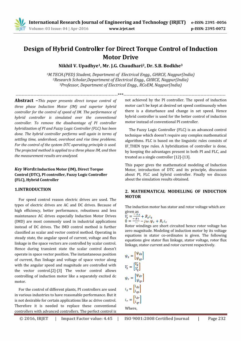
International Research Journal of Engineering and Technology (IRJET) e-ISSN: 2395 -0056
Volume: 03 Issue: 04 | Apr-2016 www.irjet.net p-ISSN: 2395-0072
© 2016, IRJET | Impact Factor value: 4.45 | ISO 9001:2008 Certified Journal | Page 232
Design of Hybrid Controller for Direct Torque Control of Induction
Motor Drive Nikhil V. Upadhye1, Mr. J.G. Chaudhari2, Dr. S.B. Bodkhe3
1M.TECH.(PED) Student, Department of Electrical Engg., GHRCE, Nagpur(India) 2Research Scholar,Department of Electrical Engg., GHRCE, Nagpur(India)
3Professor, Department of Electrical Engg., RCoEM, Nagpur(India)
---------------------------------------------------------------------***---------------------------------------------------------------------
Abstract –This paper presents direct torque control of
three phase Induction Motor (IM) and superior hybrid
controller for the control of speed of IM. The performance of
hybrid controller is simulated over the conventional
controller. To remove the disadvantage of PI controller
hybridization of PI and Fuzzy Logic Controller (FLC) has been
done. The hybrid controller performs well again in terms of
settling time, undershoot, overshoot and rise time problems.
For the control of the system DTC operating principle is used.
The projected method is applied to a three phase IM, and then
the measurement results are analyzed.
Key Words:Induction Motor (IM), Direct Torque
Control (DTC), PI controller, Fuzzy Logic Controller
(FLC), Hybrid Controller
1.INTRODUCTION
For speed control reason electric drives are used. The
types of electric drives are AC and DC drives. Because of
high efficiency, better performance, robustness and less
maintenance AC drives especially Induction Motor Drives
(IMD) are most commonly used in industrial applications
instead of DC drives. The IMD control method is further
classified as scalar and vector control method. Operating in
steady state, the angular speed of current, voltage and flux
linkage in the space vectors are controlled by scalar control.
Hence during transient state the scalar control doesn’t
operate in space vector position. The instantaneous position
of current, flux linkage and voltage of space vector along
with the angular speed and magnitude are controlled with
the vector control.[2]-[3] The vector control allows
controlling of induction motor like a separately excited dc
motor.
For the control of different plants, PI controllers are used
in various industries to have reasonable performance. But it
is not desirable for certain applications like ac drive control.
Therefore it is needed to replace these conventional
controllers with advanced controllers. The perfect control is
not achieved by the PI controller. The speed of induction
motor can’t be kept at desired set speed continuously when
there is a disturbance and change in set speed. Hence
hybrid controller is used for the better control of induction
motor instead of conventional PI controller.
The Fuzzy Logic Controller (FLC) is an advanced control
technique which doesn’t require any complex mathematical
algorithms. FLC is based on the linguistic rules consists of
IF_THEN type rules. A hybridization of controller is done,
by keeping the advantages present in both PI and FLC, and
treated as a single controller [12]-[13].
This paper gives the mathematical modeling of Induction Motor, introduction of DTC and its principle, discussion about PI, FLC and hybrid controller. Finally we discuss about the simulation results obtained.
2. MATHEMATICAL MODELLING OF INDUCTION MOTOR The induction motor has stator and rotor voltage which are given as
Rotor windings are short circuited hence rotor voltage has zero magnitude. Modeling of induction motor by its voltage equations in stator co-ordinates is given. The following equations give stator flux linkage, stator voltage, rotor flux linkage, stator current and rotor current respectively.
Where,
International Research Journal of Engineering and Technology (IRJET) e-ISSN: 2395 -0056
Volume: 03 Issue: 04 | Apr-2016 www.irjet.net p-ISSN: 2395-0072
© 2016, IRJET | Impact Factor value: 4.45 | ISO 9001:2008 Certified Journal | Page 233
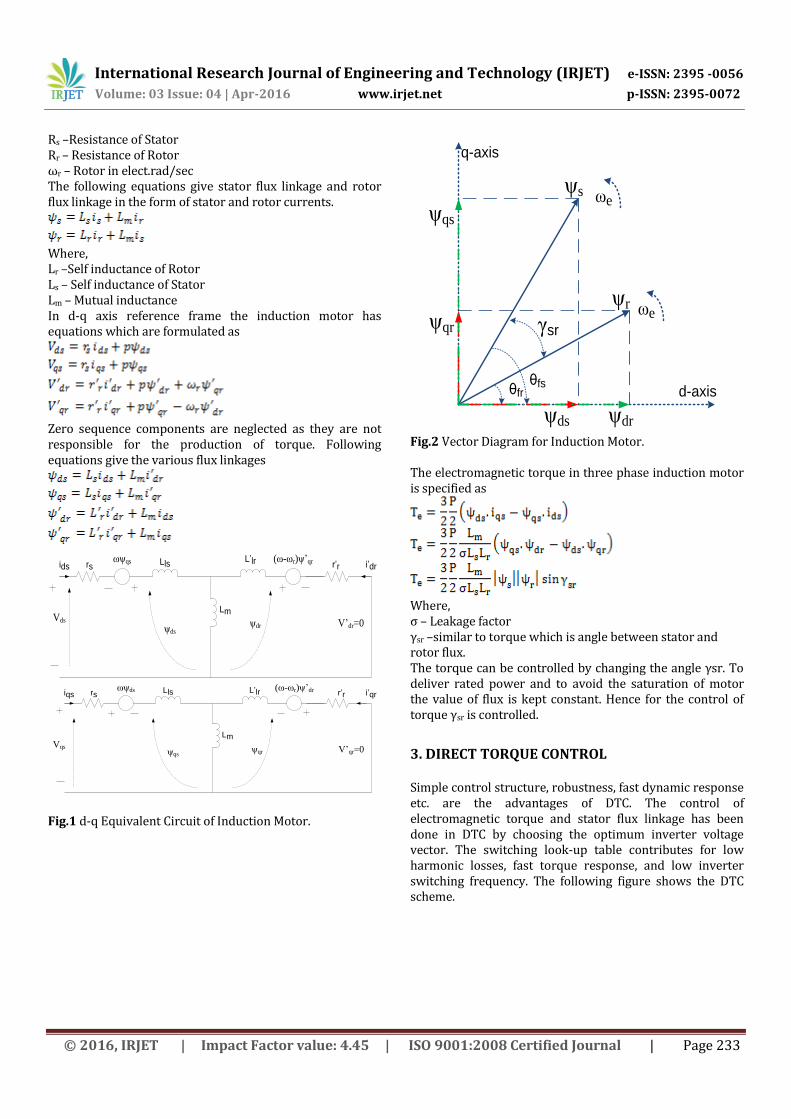
Rs –Resistance of Stator Rr – Resistance of Rotor ωr – Rotor in elect.rad/sec The following equations give stator flux linkage and rotor flux linkage in the form of stator and rotor currents.
Where, Lr –Self inductance of Rotor Ls – Self inductance of Stator Lm – Mutual inductance In d-q axis reference frame the induction motor has equations which are formulated as
Zero sequence components are neglected as they are not responsible for the production of torque. Following equations give the various flux linkages
L’lr i’dr
ωψqs (ω-ωr)ψ’qr r’rLlsrsids
Lm
ψdsψdr
Vds V’dr=0
L’lr i’qrωψds (ω-ωr)ψ’dr r’r
Llsrsiqs
Lm
ψqrψqs
Vqs V’qr=0
Fig.1 d-q Equivalent Circuit of Induction Motor.
θfsθfr
γsr
d-axis
q-axis
ωe
ωe
ψqs
ψqr
ψdrψds
ψr
ψs
Fig.2 Vector Diagram for Induction Motor. The electromagnetic torque in three phase induction motor is specified as
Where, σ – Leakage factor γsr –similar to torque which is angle between stator and rotor flux. The torque can be controlled by changing the angle γsr. To deliver rated power and to avoid the saturation of motor the value of flux is kept constant. Hence for the control of torque γsr is controlled.
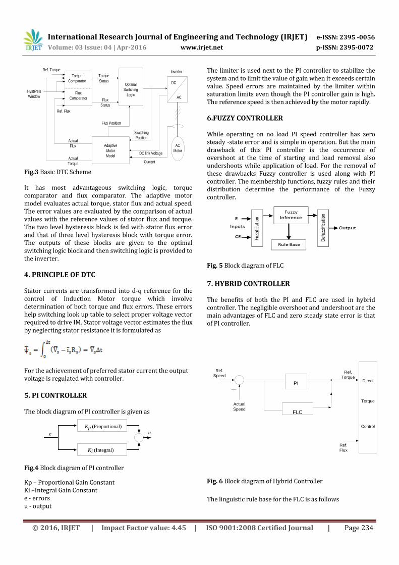
3. DIRECT TORQUE CONTROL Simple control structure, robustness, fast dynamic response etc. are the advantages of DTC. The control of electromagnetic torque and stator flux linkage has been done in DTC by choosing the optimum inverter voltage vector. The switching look-up table contributes for low harmonic losses, fast torque response, and low inverter switching frequency. The following figure shows the DTC scheme.
International Research Journal of Engineering and Technology (IRJET) e-ISSN: 2395 -0056
Volume: 03 Issue: 04 | Apr-2016 www.irjet.net p-ISSN: 2395-0072
© 2016, IRJET | Impact Factor value: 4.45 | ISO 9001:2008 Certified Journal | Page 234
Torque
Comparator
Flux
Comparator
Optimal
Switching
Logic
Adaptive
Motor
Model
AC
Motor
Flux
Status
Torque
Status
Ref. Torque
Hystersis
Window
Ref. Flux
Actual
Flux
Actual
Torque Current
DC link Voltage
Flux Position
Inverter
DC
AC
Switching
Position
Fig.3 Basic DTC Scheme It has most advantageous switching logic, torque comparator and flux comparator. The adaptive motor model evaluates actual torque, stator flux and actual speed. The error values are evaluated by the comparison of actual values with the reference values of stator flux and torque. The two level hysteresis block is fed with stator flux error and that of three level hysteresis block with torque error. The outputs of these blocks are given to the optimal switching logic block and then switching logic is provided to the inverter.
4. PRINCIPLE OF DTC Stator currents are transformed into d-q reference for the control of Induction Motor torque which involve determination of both torque and flux errors. These errors help switching look up table to select proper voltage vector required to drive IM. Stator voltage vector estimates the flux by neglecting stator resistance it is formulated as
For the achievement of preferred stator current the output voltage is regulated with controller.
5. PI CONTROLLER The block diagram of PI controller is given as
Kp (Proportional)
Ki (Integral)
e u
Fig.4 Block diagram of PI controller
Kp – Proportional Gain Constant Ki –Integral Gain Constant e - errors u - output
The limiter is used next to the PI controller to stabilize the system and to limit the value of gain when it exceeds certain value. Speed errors are maintained by the limiter within saturation limits even though the PI controller gain is high. The reference speed is then achieved by the motor rapidly.
6.FUZZY CONTROLLER
While operating on no load PI speed controller has zero steady -state error and is simple in operation. But the main drawback of this PI controller is the occurrence of overshoot at the time of starting and load removal also undershoots while application of load. For the removal of these drawbacks Fuzzy controller is used along with PI controller. The membership functions, fuzzy rules and their distribution determine the performance of the Fuzzy controller.
Fig. 5 Block diagram of FLC
7. HYBRID CONTROLLER The benefits of both the PI and FLC are used in hybrid controller. The negligible overshoot and undershoot are the main advantages of FLC and zero steady state error is that of PI controller.
PI
FLC
Ref.
SpeedRef.
Torque
Actual
Speed
Direct
Torque
Control
Ref.
Flux
Fig. 6 Block diagram of Hybrid Controller
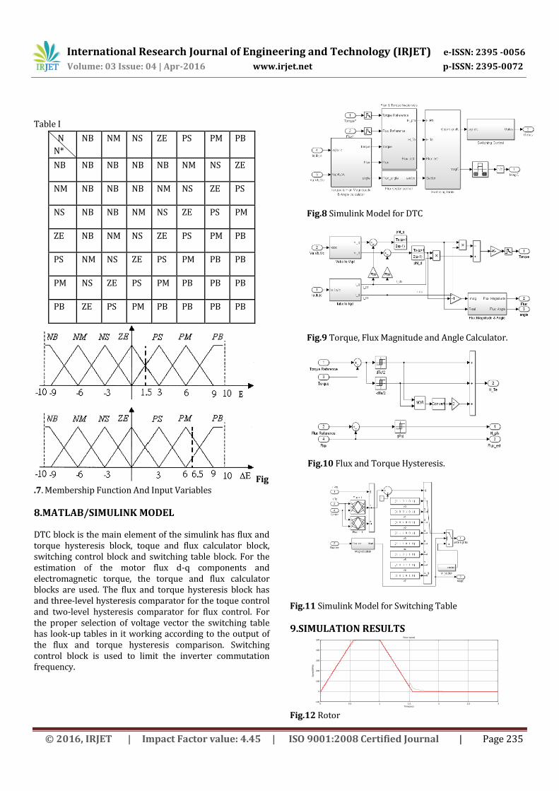
The linguistic rule base for the FLC is as follows
International Research Journal of Engineering and Technology (IRJET) e-ISSN: 2395 -0056
Volume: 03 Issue: 04 | Apr-2016 www.irjet.net p-ISSN: 2395-0072
© 2016, IRJET | Impact Factor value: 4.45 | ISO 9001:2008 Certified Journal | Page 235
Table I
N
N*
NB NM NS ZE PS PM PB
NB NB NB NB NB NM NS ZE
NM NB NB NB NM NS ZE PS
NS NB NB NM NS ZE PS PM
ZE NB NM NS ZE PS PM PB
PS NM NS ZE PS PM PB PB
PM NS ZE PS PM PB PB PB
PB ZE PS PM PB PB PB PB
Fig.7. Membership Function And Input Variables
8.MATLAB/SIMULINK MODEL
DTC block is the main element of the simulink has flux and torque hysteresis block, toque and flux calculator block, switching control block and switching table block. For the estimation of the motor flux d-q components and electromagnetic torque, the torque and flux calculator blocks are used. The flux and torque hysteresis block has and three-level hysteresis comparator for the toque control and two-level hysteresis comparator for flux control. For the proper selection of voltage vector the switching table has look-up tables in it working according to the output of the flux and torque hysteresis comparison. Switching control block is used to limit the inverter commutation frequency.
Fig.8 Simulink Model for DTC
Fig.9 Torque, Flux Magnitude and Angle Calculator.
Fig.10 Flux and Torque Hysteresis.
Fig.11 Simulink Model for Switching Table
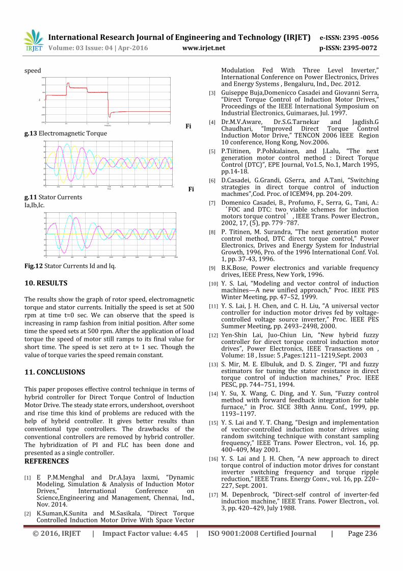
9.SIMULATION RESULTS
0 0.5 1 1.5 2 2.5 3-100
0
100
200
300
400
500
Time(sec)
Speed(R
PM
)
Rotor speed
Fig.12 Rotor
International Research Journal of Engineering and Technology (IRJET) e-ISSN: 2395 -0056
Volume: 03 Issue: 04 | Apr-2016 www.irjet.net p-ISSN: 2395-0072
© 2016, IRJET | Impact Factor value: 4.45 | ISO 9001:2008 Certified Journal | Page 236
speed
0 0.5 1 1.5 2 2.5 3-1500
-1000
-500
0
500
1000
1500
Time(sec)
Nm
Electromagnetic Torque
Fig.13 Electromagnetic Torque
0 0.01 0.02 0.03 0.04 0.05 0.06 0.07 0.08 0.09 0.1-80
-60
-40
-20
0
20
40
60
80
Time Fig.11 Stator Currents Ia,Ib,Ic.
0 200 400 600 800 1000 1200 1400 1600 1800 2000-80
-60
-40
-20
0
20
40
60
80
Fig.12 Stator Currents Id and Iq.
10. RESULTS
The results show the graph of rotor speed, electromagnetic torque and stator currents. Initially the speed is set at 500 rpm at time t=0 sec. We can observe that the speed is increasing in ramp fashion from initial position. After some time the speed sets at 500 rpm. After the application of load torque the speed of motor still ramps to its final value for short time. The speed is set zero at t= 1 sec. Though the value of torque varies the speed remain constant.
11. CONCLUSIONS This paper proposes effective control technique in terms of hybrid controller for Direct Torque Control of Induction Motor Drive. The steady state errors, undershoot, overshoot and rise time this kind of problems are reduced with the help of hybrid controller. It gives better results than conventional type controllers. The drawbacks of the conventional controllers are removed by hybrid controller. The hybridization of PI and FLC has been done and presented as a single controller.
REFERENCES [1] E P.M.Menghal and Dr.A.Jaya laxmi, “Dynamic
Modeling, Simulation & Analysis of Induction Motor Drives,” International Conference on Science,Engineering and Management, Chennai, Ind., Nov. 2014.
[2] K.Suman,K.Sunita and M.Sasikala, “Direct Torque Controlled Induction Motor Drive With Space Vector
Modulation Fed With Three Level Inverter,” International Conference on Power Electronics, Drives and Energy Systems , Bengaluru, Ind., Dec. 2012.
[3] Guiseppe Buja,Domenicco Casadei and Giovanni Serra, “Direct Torque Control of Induction Motor Drives,” Proceedings of the IEEE International Symposium on Industrial Electronics, Guimaraes, Jul. 1997.
[4] Dr.M.V.Aware, Dr.S.G.Tarnekar and Jagdish.G Chaudhari, “Improved Direct Torque Control Induction Motor Drive,” TENCON 2006 IEEE Region 10 conference, Hong Kong, Nov.2006.
[5] P.Tiitinen, P.Pohkalainen, and J.Lalu, “The next generation motor control method : Direct Torque Control (DTC)”, EPE Journal, Vo1.5, No.1, March 1995, pp.14-18.
[6] D.Casadei, G.Grandi, GSerra, and A.Tani, “Switching strategies in direct torque control of induction machmes”,Cod. Proc. of ICEM94, pp. 204-209.
[7] Domenico Casadei, B., Profumo, F., Serra, G., Tani, A.: ‘FOC and DTC: two viable schemes for induction motors torque control’, IEEE Trans. Power Electron., 2002, 17, (5), pp. 779–787.
[8] P. Titinen, M. Surandra, ”The next generation motor control method, DTC direct torque control,” Power Electronics, Drives and Energy System for Industrial Growth, 1996, Pro. of the 1996 International Conf. Vol. 1, pp. 37-43, 1996.
[9] B.K.Bose, Power electronics and variable frequency drives, IEEE Press, New York, 1996.
[10] Y. S. Lai, “Modeling and vector control of induction machines—A new unified approach,” Proc. IEEE PES Winter Meeting, pp. 47–52, 1999.
[11] Y. S. Lai, J. H. Chen, and C. H. Liu, “A universal vector controller for induction motor drives fed by voltage-controlled voltage source inverter,” Proc. IEEE PES Summer Meeting, pp. 2493–2498, 2000.
[12] Yen-Shin Lai, Juo-Chiun Lin, “New hybrid fuzzy controller for direct torque control induction motor drives”, Power Electronics, IEEE Transactions on , Volume: 18 , Issue: 5 ,Pages:1211–1219,Sept. 2003
[13] S. Mir, M. E. Elbuluk, and D. S. Zinger, “PI and fuzzy estimators for tuning the stator resistance in direct torque control of induction machines,” Proc. IEEE PESC, pp. 744–751, 1994.
[14] Y. Su, X. Wang, C. Ding, and Y. Sun, “Fuzzy control method with forward feedback integration for table furnace,” in Proc. SICE 38th Annu. Conf., 1999, pp. 1193–1197.
[15] Y. S. Lai and Y. T. Chang, “Design and implementation of vector-controlled induction motor drives using random switching technique with constant sampling frequency,” IEEE Trans. Power Electron., vol. 16, pp. 400–409, May 2001.
[16] Y. S. Lai and J. H. Chen, “A new approach to direct torque control of induction motor drives for constant inverter switching frequency and torque ripple reduction,” IEEE Trans. Energy Conv., vol. 16, pp. 220–227, Sept. 2001.
[17] M. Depenbrock, “Direct-self control of inverter-fed induction machine,” IEEE Trans. Power Electron., vol. 3, pp. 420–429, July 1988.
Recommended