FACTA UNIVERSITATIS
Series: Electronics and Energetics Vol. 28, No 4, December 2015, pp. 527 - 540
DOI: 10.2298/FUEE1504527S
DETECTION AND SUPPRESSION OF PARASITIC DC
VOLTAGES IN 400 V AC GRIDS
Slobodan N. Vukosavic
University of Belgrade, Dept. of Electrical Engineering, 11000 Belgrade, Serbia
Abstract. Grid connected static power converters inject parasitic DC currents due to
the offset in current sensing, control imperfections, asymmetries in power switches and
other secondary effects. Ever growing number of grid connected converters contributes
to an increase of DC bias in AC grids, and this brings the cores of distribution transformers
closer to saturation and increases their power losses. This paper provides sensitivity
analysis of distribution transformers to the DC bias, and considers solutions for detecting
and compensating the parasitic DC components in AC grids. Active compensation
methods can be advantageously used in suppressing the DC bias at grid connection point
of the power converter. The sensing approach proposed in this paper makes use of saturable
ferromagnetic cores and a low cost DSP for signal analysis and processing. Proposed
algorithm uses distortion of the magnetizing current of a parallel connected saturable core
due to the bias. Experimental results demonstrate the capability for detecting and
compensating the bias voltages far below 1 mV in 0.4 kV grids. The paper describes the
principles of DC bias detection and it provides the guidelines for the proper design of
magnetic components. High precision of the proposed DC bias sensing is thoroughly
verified on the experimental setup connected to a 0.4 kV grid.
Key words: Power quality, distribution transformers, power converters, dc bias.
1. INTRODUCTION
DC injection into the low-voltage and medium-voltage AC grids comes mostly from
grid connected static power converters. Recent developments in power electronics, electrical
drives and distributed generation leads to a large number of static power converters
connected to the grid, with the potential to inject a parasitic DC bias into the grid. Static
power converters with PWM control can produce AC waveforms with a low distortion factor
[1], but they can also introduce parasitic spectral components, including the DC bias.
Numerical solutions can be used to reduce the parasitic spectral components [2], but the
remaining DC offset cannot be eliminated completely. Therefore, all the transformerless
Received March 22, 2015
Corresponding author: Slobodan N. Vukosavic
University of Belgrade, Dept. of Electrical Engineering, 11000 Belgrade, Serbia
(e-mail: [email protected])
528 S. N. VUKOSAVIC
grid-connected power converters have the potential of introducing a small, parasitic DC
offset into the AC grid [3]. Widespread use of electronically controlled electrical drives [4],
which are often regenerative, makes the problem even more emphasized. Recently
introduced multiphase and multimotor drives [5] are also capable of introducing a parasitic
DC bias through the front end converter. Hence, whenever the power interface to the grid is
performed through a static power converter, there is a potential of DC bias in AC grids has
an adverse effect on the operation of power transformers [6,7]. Adverse consequences are
also possible in certain electrical loads [8]. Widespread use of distributed power sources
attached to the grid through a power electronics interface, as well as an increased use of
active rectifiers in modern electrical speed drives [9] and static power converters [10]
emphasizes the problem of DC injection. DC bias currents limits specified by the norms [11]
and discussed by international working groups are difficult to measure. Consequential DC
bias voltages are even lower due to very low equivalent resistance in AC grids. Therefore,
the need emerges to measure DC bias voltages and currents in AC grids with high precision.
DC injection of grid connected power converters is caused by the delay mismatch in
gating circuits and imperfections of power switches [12], by the offset in current sensing
[13], by DC injection based methods for detecting the stator resistance and temperature in
grid-connected AC machines [14], while other sources of DC bias include geomagnetic
induced currents [15], HVDC transmission, railway signalling equipment and similar.
Even a small DC bias may result in saturation of power transformers [16], an increase in
their iron losses, increased corrosion and erroneous operation of measurement and
protective equipment. Relevant norms [11] prescribe the DC injection limit as 0.5% of the
grid-connected power converter rated current. On the other hand, a DC bias of 0.5% of
the rated current of Sn > 500 kVA distribution transformer [17,18] corresponds to more
than 50% of the rated magnetizing current, and this would saturate the core and trip the
protections. Considering ever growing number of grid connected static power converters,
it is essential do devise and use devices for DC bias detection and compensation [10].
Distribution power transformers with 0.4 kV secondary windings have a very low
winding resistance and a very low magnetizing current [17,18]. A DC bias voltage of only
1mV may introduce a 5% offset in the magnetizing current, moving the H field in B-H
plane away from the origin. Parasitic DC current in a transformer results in half-cycle
saturation and an increase in reactive power, leakage flux, stray losses and temperature of
the core, clamping plates, the tank walls and bolts. Therefore, DC bias detection and
compensation is required to suppress the parasitic DC voltages in 0.4 kV grid far below
1 mV level. Transformerless grid-connected power converters are the source of the DC
injection. Equipped with adequate DC bias sensing and controls [19], they can be also
used for suppressing the parasitic DC voltages at the grid connection point.
It is rather difficult to measure very small DC offsets embedded in AC voltages, as the
ratio between the two exceeds 105-10
6. Required precision of 2-3 ppm has to be maintained
over the range of operating conditions. This cannot be achieved even with advanced sensors
[13, 20]. Considerable effort has been made in improving precision of DC bias sensing [9,
19, 21, 22] and applying novel sensing techniques within closed loop DC bias suppression
systems [10, 12, 23, 24]. In grid connected power converters with intermediate DC link
circuit, parasitic DC injection can be determined from line frequency oscillations of the DC
link voltage [10] with precision of 0.1%. At the same time, the offset introduced by Hall
effect current sensors replaced in the DC link can be removed by auto-calibration [12].
Detection and Suppression of Parasitic DC Voltages in 400 V AC Grids 529
DC injection can be also suppressed [23] by inserting an isolating power transformer, by
using the half bridge topologies, or by inserting a series blocking capacitor, but these
methods increase the cost, size and power losses. Therefore, the efforts were mainly focused
towards improving the accuracy of DC bias methods and devices [13, 18-26]. In most
cases, proposed reading of very small DC bias in the presence of a large AC signal is based
on nonlinear effects in AC excited, DC biased iron cores. Even a small bias results in
detectable amounts of even harmonics [29-32] in distorted magnetizing current of saturable
iron cores. Parasitic DC voltage in AC grid can be detected by processing the magnetizing
current Im in parallel connected choke wound on saturable iron core. DC bias sensing
proposed in [19, 21, 22, 24-26] compares the positive and negative peaks of the magnetizing
current, which gets distorted in the presence of a DC bias. Used in conjunction with an 8A
transformerless power converter [24, 25], it suppresses the DC injection to 4mA. The same
Im peak comparing method can be advantageously used [26] in suppressing magnetic
saturation in transformers used to connect a static power converter to the grid. With
additional compensation winding on parallel connected choke [21, 22], the peak comparing
method can be used to measure the DC bias in 0.4kV AC grids, offering precision better
than 3mV for phase voltages Uph = [170V .. 220V].
In this paper, the problems of detecting and suppressing the DC bias in AC grids is
discussed and analyzed. An overview of sensing methods is followed by the proposal of a
new, improved sensing technique based on nonlinearity of parallel connected choke, wound
on a saturable iron core [29]. The main objective is achieving precision in DC bias sensing
considerably better than 1 mV in 0.4 kV grids. The two main tools in achieving this goal are
(i) the algorithm of detecting the bias and (ii) the approach to winding the choke and
designing the filters.
Section II provides a brief analysis distribution transformer parameters and studies the
effects of parasitic DC voltages in 0.4kV grids, reinstating the required precision of DC
bias sensing. In Section III, the state of the art sensing solutions are considered with the
aim of identifying the factors that limit their accuracy. Proposed guidelines to designing
magnetics are summarized in Section IV. The algorithm proposed to suppress the DC bias
is given in Section V, while Section VI summarizes experimental results. Discussion and
conclusions are given in Section VII.
2. REQUIRED ACCURACY OF DC BIAS SENSING
DC bias currents may have a detrimental effect on the integrity of the distribution and
power transformers or their long term performance, which has a negative effect on the
overall system reliability.
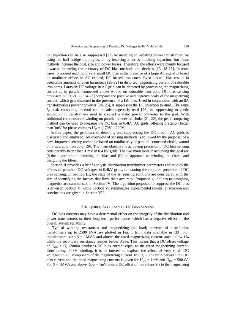
Typical winding resistances and magnetizing (no load) currents of distribution
transformers up to 2500 kVA are plotted in Fig. 1 from data available in [33]. For
transformers rated S = 1MVA and above, the rated magnetizing current stays below 1%
while the secondary resistance resides below 0.5%. This means that a DC offset voltage
of UDC > Un /20000 produces DC bias current equal to the rated magnetizing current.
Considering 0.4kV winding, it is of interest to explore the effect of very small DC
voltages on DC component of the magnetizing current. In Fig. 2, the ratio between the DC
bias current and the rated magnetizing currents is given for UDC = 1mV and UDC = 500V.
For S = 1MVA and above, UDC = 1mV adds a DC offset of more than 5% to the magnetizing
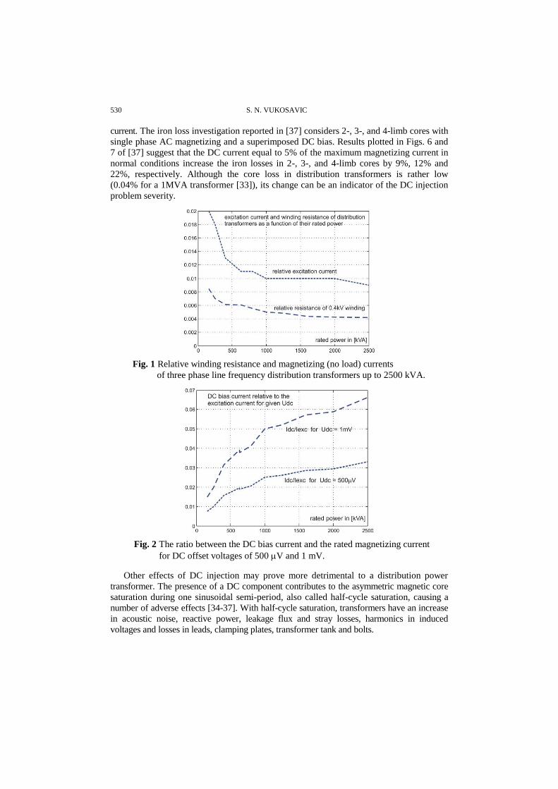
530 S. N. VUKOSAVIC
current. The iron loss investigation reported in [37] considers 2-, 3-, and 4-limb cores with
single phase AC magnetizing and a superimposed DC bias. Results plotted in Figs. 6 and
7 of [37] suggest that the DC current equal to 5% of the maximum magnetizing current in
normal conditions increase the iron losses in 2-, 3-, and 4-limb cores by 9%, 12% and
22%, respectively. Although the core loss in distribution transformers is rather low
(0.04% for a 1MVA transformer [33]), its change can be an indicator of the DC injection
problem severity.
Fig. 1 Relative winding resistance and magnetizing (no load) currents
of three phase line frequency distribution transformers up to 2500 kVA.
Fig. 2 The ratio between the DC bias current and the rated magnetizing current
for DC offset voltages of 500 V and 1 mV.
Other effects of DC injection may prove more detrimental to a distribution power
transformer. The presence of a DC component contributes to the asymmetric magnetic core
saturation during one sinusoidal semi-period, also called half-cycle saturation, causing a
number of adverse effects [34-37]. With half-cycle saturation, transformers have an increase
in acoustic noise, reactive power, leakage flux and stray losses, harmonics in induced
voltages and losses in leads, clamping plates, transformer tank and bolts.
Detection and Suppression of Parasitic DC Voltages in 400 V AC Grids 531
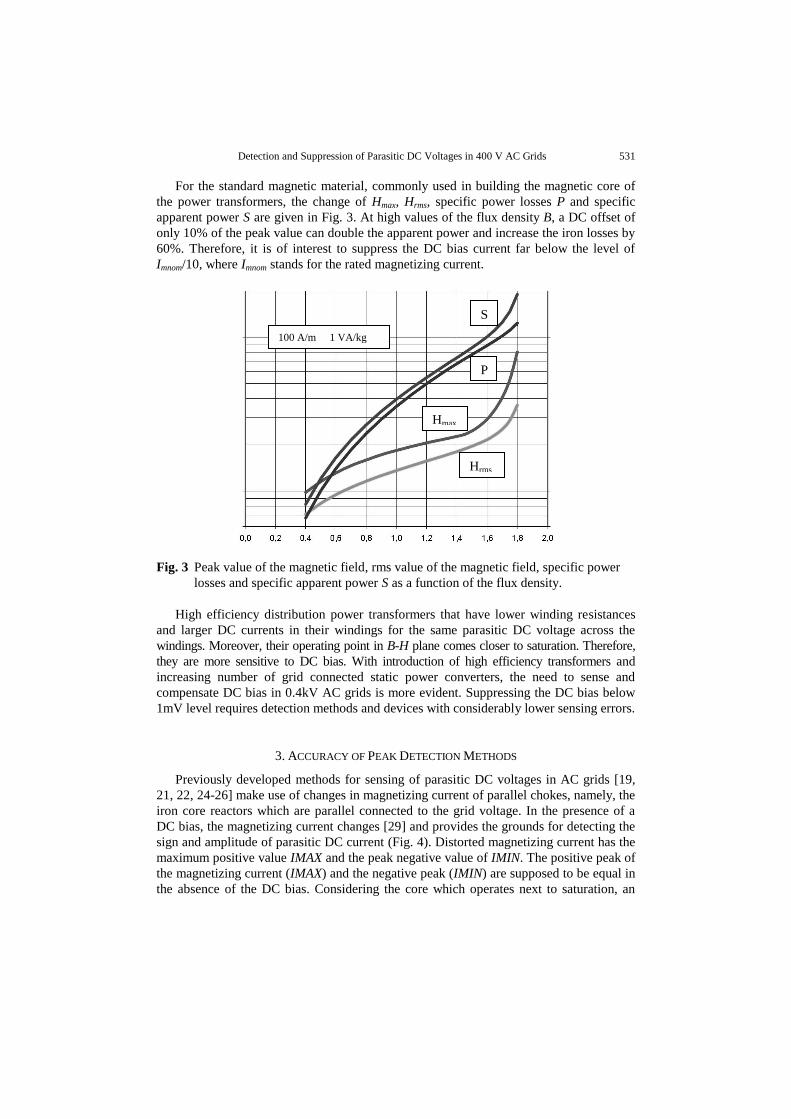
For the standard magnetic material, commonly used in building the magnetic core of
the power transformers, the change of Hmax, Hrms, specific power losses P and specific
apparent power S are given in Fig. 3. At high values of the flux density B, a DC offset of
only 10% of the peak value can double the apparent power and increase the iron losses by
60%. Therefore, it is of interest to suppress the DC bias current far below the level of
Imnom/10, where Imnom stands for the rated magnetizing current.
Fig. 3 Peak value of the magnetic field, rms value of the magnetic field, specific power
losses and specific apparent power S as a function of the flux density.
High efficiency distribution power transformers that have lower winding resistances
and larger DC currents in their windings for the same parasitic DC voltage across the
windings. Moreover, their operating point in B-H plane comes closer to saturation. Therefore,
they are more sensitive to DC bias. With introduction of high efficiency transformers and
increasing number of grid connected static power converters, the need to sense and
compensate DC bias in 0.4kV AC grids is more evident. Suppressing the DC bias below
1mV level requires detection methods and devices with considerably lower sensing errors.
3. ACCURACY OF PEAK DETECTION METHODS
Previously developed methods for sensing of parasitic DC voltages in AC grids [19,
21, 22, 24-26] make use of changes in magnetizing current of parallel chokes, namely, the
iron core reactors which are parallel connected to the grid voltage. In the presence of a
DC bias, the magnetizing current changes [29] and provides the grounds for detecting the
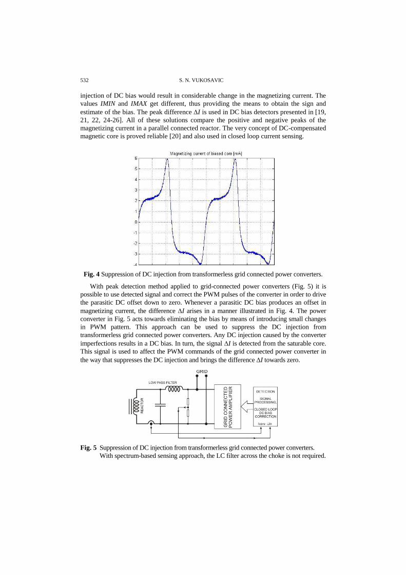
sign and amplitude of parasitic DC current (Fig. 4). Distorted magnetizing current has the
maximum positive value IMAX and the peak negative value of IMIN. The positive peak of
the magnetizing current (IMAX) and the negative peak (IMIN) are supposed to be equal in
the absence of the DC bias. Considering the core which operates next to saturation, an
Hmax
P
S
Hrms
100 A/m 1 VA/kg
532 S. N. VUKOSAVIC
injection of DC bias would result in considerable change in the magnetizing current. The
values IMIN and IMAX get different, thus providing the means to obtain the sign and
estimate of the bias. The peak difference I is used in DC bias detectors presented in [19,
21, 22, 24-26]. All of these solutions compare the positive and negative peaks of the
magnetizing current in a parallel connected reactor. The very concept of DC-compensated
magnetic core is proved reliable [20] and also used in closed loop current sensing.
Fig. 4 Suppression of DC injection from transformerless grid connected power converters.
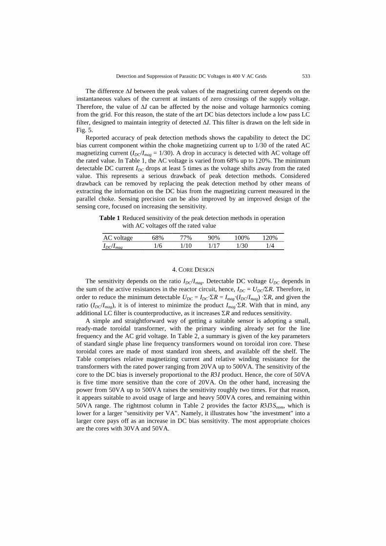
With peak detection method applied to grid-connected power converters (Fig. 5) it is
possible to use detected signal and correct the PWM pulses of the converter in order to drive
the parasitic DC offset down to zero. Whenever a parasitic DC bias produces an offset in
magnetizing current, the difference I arises in a manner illustrated in Fig. 4. The power
converter in Fig. 5 acts towards eliminating the bias by means of introducing small changes
in PWM pattern. This approach can be used to suppress the DC injection from
transformerless grid connected power converters. Any DC injection caused by the converter
imperfections results in a DC bias. In turn, the signal I is detected from the saturable core.
This signal is used to affect the PWM commands of the grid connected power converter in
the way that suppresses the DC injection and brings the difference I towards zero.
Fig. 5 Suppression of DC injection from transformerless grid connected power converters.
With spectrum-based sensing approach, the LC filter across the choke is not required.
Detection and Suppression of Parasitic DC Voltages in 400 V AC Grids 533
The difference I between the peak values of the magnetizing current depends on the
instantaneous values of the current at instants of zero crossings of the supply voltage.
Therefore, the value of I can be affected by the noise and voltage harmonics coming
from the grid. For this reason, the state of the art DC bias detectors include a low pass LC
filter, designed to maintain integrity of detected I. This filter is drawn on the left side in
Fig. 5.
Reported accuracy of peak detection methods shows the capability to detect the DC
bias current component within the choke magnetizing current up to 1/30 of the rated AC
magnetizing current (IDC/Imag = 1/30). A drop in accuracy is detected with AC voltage off
the rated value. In Table 1, the AC voltage is varied from 68% up to 120%. The minimum
detectable DC current IDC drops at least 5 times as the voltage shifts away from the rated
value. This represents a serious drawback of peak detection methods. Considered
drawback can be removed by replacing the peak detection method by other means of
extracting the information on the DC bias from the magnetizing current measured in the
parallel choke. Sensing precision can be also improved by an improved design of the
sensing core, focused on increasing the sensitivity.
Table 1 Reduced sensitivity of the peak detection methods in operation
with AC voltages off the rated value
AC voltage 68% 77% 90% 100% 120%
IDC/Imag 1/6 1/10 1/17 1/30 1/4
4. CORE DESIGN
The sensitivity depends on the ratio IDC/Imag. Detectable DC voltage UDC depends in
the sum of the active resistances in the reactor circuit, hence, IDC = UDC/R. Therefore, in
order to reduce the minimum detectable UDC = IDCR = Imag(IDC/Imag) R, and given the
ratio (IDC/Imag), it is of interest to minimize the product ImagR. With that in mind, any
additional LC filter is counterproductive, as it increases R and reduces sensitivity.
A simple and straightforward way of getting a suitable sensor is adopting a small,
ready-made toroidal transformer, with the primary winding already set for the line
frequency and the AC grid voltage. In Table 2, a summary is given of the key parameters
of standard single phase line frequency transformers wound on toroidal iron core. These
toroidal cores are made of most standard iron sheets, and available off the shelf. The
Table comprises relative magnetizing current and relative winding resistance for the
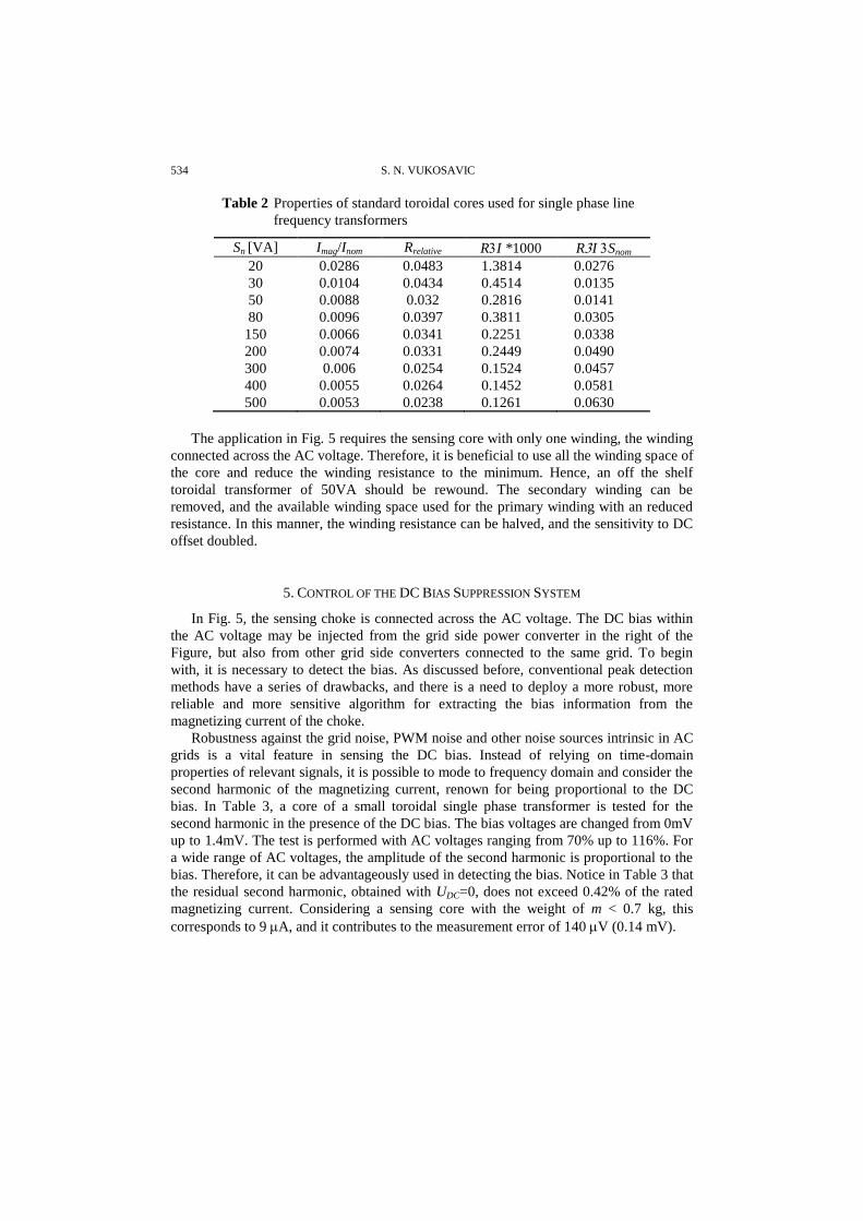
transformers with the rated power ranging from 20VA up to 500VA. The sensitivity of the
core to the DC bias is inversely proportional to the RI product. Hence, the core of 50VA
is five time more sensitive than the core of 20VA. On the other hand, increasing the
power from 50VA up to 500VA raises the sensitivity roughly two times. For that reason,
it appears suitable to avoid usage of large and heavy 500VA cores, and remaining within
50VA range. The rightmost column in Table 2 provides the factor RISnom, which is
lower for a larger "sensitivity per VA". Namely, it illustrates how "the investment" into a
larger core pays off as an increase in DC bias sensitivity. The most appropriate choices
are the cores with 30VA and 50VA.
534 S. N. VUKOSAVIC
Table 2 Properties of standard toroidal cores used for single phase line
frequency transformers
Sn [VA] Imag/Inom Rrelative RI *1000 RI Snom
20 0.0286 0.0483 1.3814 0.0276
30 0.0104 0.0434 0.4514 0.0135
50 0.0088 0.032 0.2816 0.0141
80 0.0096 0.0397 0.3811 0.0305
150 0.0066 0.0341 0.2251 0.0338
200 0.0074 0.0331 0.2449 0.0490
300 0.006 0.0254 0.1524 0.0457
400 0.0055 0.0264 0.1452 0.0581
500 0.0053 0.0238 0.1261 0.0630
The application in Fig. 5 requires the sensing core with only one winding, the winding
connected across the AC voltage. Therefore, it is beneficial to use all the winding space of
the core and reduce the winding resistance to the minimum. Hence, an off the shelf
toroidal transformer of 50VA should be rewound. The secondary winding can be
removed, and the available winding space used for the primary winding with an reduced
resistance. In this manner, the winding resistance can be halved, and the sensitivity to DC
offset doubled.
5. CONTROL OF THE DC BIAS SUPPRESSION SYSTEM
In Fig. 5, the sensing choke is connected across the AC voltage. The DC bias within
the AC voltage may be injected from the grid side power converter in the right of the
Figure, but also from other grid side converters connected to the same grid. To begin
with, it is necessary to detect the bias. As discussed before, conventional peak detection
methods have a series of drawbacks, and there is a need to deploy a more robust, more
reliable and more sensitive algorithm for extracting the bias information from the
magnetizing current of the choke.
Robustness against the grid noise, PWM noise and other noise sources intrinsic in AC
grids is a vital feature in sensing the DC bias. Instead of relying on time-domain
properties of relevant signals, it is possible to mode to frequency domain and consider the
second harmonic of the magnetizing current, renown for being proportional to the DC
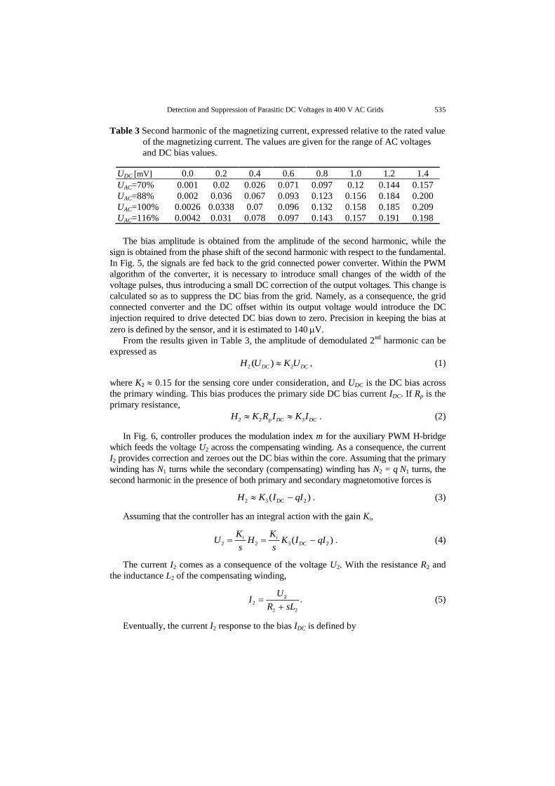
bias. In Table 3, a core of a small toroidal single phase transformer is tested for the
second harmonic in the presence of the DC bias. The bias voltages are changed from 0mV
up to 1.4mV. The test is performed with AC voltages ranging from 70% up to 116%. For
a wide range of AC voltages, the amplitude of the second harmonic is proportional to the
bias. Therefore, it can be advantageously used in detecting the bias. Notice in Table 3 that
the residual second harmonic, obtained with UDC=0, does not exceed 0.42% of the rated
magnetizing current. Considering a sensing core with the weight of m < 0.7 kg, this
corresponds to 9 A, and it contributes to the measurement error of 140 V (0.14 mV).
Detection and Suppression of Parasitic DC Voltages in 400 V AC Grids 535
Table 3 Second harmonic of the magnetizing current, expressed relative to the rated value
of the magnetizing current. The values are given for the range of AC voltages
and DC bias values.
UDC [mV] 0.0 0.2 0.4 0.6 0.8 1.0 1.2 1.4
UAC=70% 0.001 0.02 0.026 0.071 0.097 0.12 0.144 0.157
UAC=88% 0.002 0.036 0.067 0.093 0.123 0.156 0.184 0.200
UAC=100% 0.0026 0.0338 0.07 0.096 0.132 0.158 0.185 0.209
UAC=116% 0.0042 0.031 0.078 0.097 0.143 0.157 0.191 0.198
The bias amplitude is obtained from the amplitude of the second harmonic, while the
sign is obtained from the phase shift of the second harmonic with respect to the fundamental.
In Fig. 5, the signals are fed back to the grid connected power converter. Within the PWM
algorithm of the converter, it is necessary to introduce small changes of the width of the
voltage pulses, thus introducing a small DC correction of the output voltages. This change is
calculated so as to suppress the DC bias from the grid. Namely, as a consequence, the grid
connected converter and the DC offset within its output voltage would introduce the DC
injection required to drive detected DC bias down to zero. Precision in keeping the bias at
zero is defined by the sensor, and it is estimated to 140 V.
From the results given in Table 3, the amplitude of demodulated 2nd
harmonic can be
expressed as
2 2( )DC DCH U K U , (1)
where K2 0.15 for the sensing core under consideration, and UDC is the DC bias across
the primary winding. This bias produces the primary side DC bias current IDC. If Rp is the
primary resistance,
2 2 3p DC DCH K R I K I . (2)
In Fig. 6, controller produces the modulation index m for the auxiliary PWM H-bridge
which feeds the voltage U2 across the compensating winding. As a consequence, the current
I2 provides correction and zeroes out the DC bias within the core. Assuming that the primary
winding has N1 turns while the secondary (compensating) winding has N2 = q N1 turns, the
second harmonic in the presence of both primary and secondary magnetomotive forces is
2 3 2( )DCH K I qI . (3)
Assuming that the controller has an integral action with the gain Ki,
2 2 3 2( )i i
DC
K KU H K I qI
s s . (4)
The current I2 comes as a consequence of the voltage U2. With the resistance R2 and
the inductance L2 of the compensating winding,
22
2 2
.U
IR sL
(5)
Eventually, the current I2 response to the bias IDC is defined by

536 S. N. VUKOSAVIC
32 2
2 2 3
( ) ( ).iDC
i
K KI s I s
s L sR K K q
(6)
Dynamic response of the closed loop can be tuned by the gain Ki. Since the DC bias
fluctuations are rather slow, there is no need to select excessively fast response and too
large gain. In the experimental setup, response time is characterized by the time constants
of 200ms. In steady state conditions, the current I2 is proportional to the bias IDC, and it
reflects the bias voltage UDC of the grid at the point of the common connecctions (PCC).
2
1( ) ( ).DCI I
q (7)
Fig. 6 Using the sensing reactor with the compensating winding. Control circuit sets
the voltage U2 in order to obtain the current I2 of the compensating winding
which zeroes out the offset from the sensing core.
While the circuit in Fig. 6 detects the DC bias within the AC grid, the setup in Fig. 7
can be used to perform an active action and compensate the bias. The controller senses
the second harmonic and introduces the correction m of the modulation index which is
used within the grid connected power converter. In this way, a DC current I2 is injected into
the grid. When the controller reaches the balance, the current I2 zeroes out the original DC
bias of the grid and brings the voltage UDC to the zero.
Fig. 7 Using the grid connected power converter as an actuator in closed loop DC bias
suppression system. Control circuit detects the second harmonic, concludes on the
DC bias, and produces the DC voltage correction U2. This voltage injects the DC
current I2 which zeroes out the DC bias detected across the grid connection.

Detection and Suppression of Parasitic DC Voltages in 400 V AC Grids 537
6. EXPERIMENTAL RESULTS
The setup in Figs. 5 and 7 comprises the sensing choke, the signal processing block and
the grid connected power converter capable of injecting a controllable DC bias. The closed
loop gains of the bias-removal control loop are set to obtain the closed loop response
characterized by the time constant of 150 ms. Experimental results are given in Fig. 8, where
the trace of detected DC bias illustrates the operation of the DC bias suppression controller.
The scaling is 500ms per division on the x-axis and 0.5mV per division on vertical axis. An
artificial bias of 2.5mV is introduced into the systems, and it is removed in, roughly, 200ms.
Fig. 8 Transient response of the DC bias suppression controller. The scaling of x-axis is
500ms per division. The vertical axis shows detected DC bias with the scaling of
0.5mV per division. An artificial bias of 2.5mV is introduced into the systems, and
it is removed in, roughly, 200ms.
Steady state accuracy is tested in regimes where the sensing is more difficult, namely,
with AV voltage reduced to 70%, where the DC bias has a lesser effect on distortion of the
magnetizing current.
For the close-loop DC bias suppression, given in Fig. 7, the results are given in Table
4 for a range. These results present the residual error for a range of DC bias voltages. These
results demonstrate that, for a range of operating conditions, precision in sensing and removing
the DC bias can be maintained with residual errors inferior to 140 V. Considering the
amplitude of superimposed AC voltages, this results brings the measurement precision better
than 1 ppm.
Table 4 Steady state accuracy of the proposed solution
UDC [mV] 0.0 0.2 0.4 0.6 0.8 1.0 1.2 1.4
Residual error in [V] 80 101 33 129 117 57 73 17
538 S. N. VUKOSAVIC
-1 -0.5 0 0.5 1 1.5-100
-50
0
50
100
150ACCURACY IN DETECTING DC BIAS
PARASITIC DC VOLTAGE BIAS
RE
SID
UA
L E
RR
OR
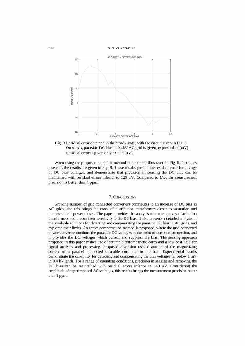
Fig. 9 Residual error obtained in the steady state, with the circuit given in Fig. 6.
On x-axis, parasitic DC bias in 0.4kV AC grid is given, expressed in [mV].
Residual error is given on y-axis in [V].
When using the proposed detection method in a manner illustrated in Fig. 6, that is, as
a sensor, the results are given in Fig. 9. These results present the residual error for a range
of DC bias voltages, and demonstrate that precision in sensing the DC bias can be
maintained with residual errors inferior to 125 V. Compared to UAC, the measurement
precision is better than 1 ppm.
7. CONCLUSIONS
Growing number of grid connected converters contributes to an increase of DC bias in
AC grids, and this brings the cores of distribution transformers closer to saturation and
increases their power losses. The paper provides the analysis of contemporary distribution
transformers and probes their sensitivity to the DC bias. It also presents a detailed analysis of
the available solutions for detecting and compensating the parasitic DC bias in AC grids, and
explored their limits. An active compensation method is proposed, where the grid connected
power converter monitors the parasitic DC voltages at the point of common connection, and
it provides the DC voltages which correct and suppress the bias. The sensing approach
proposed in this paper makes use of saturable ferromagnetic cores and a low cost DSP for
signal analysis and processing. Proposed algorithm uses distortion of the magnetizing
current of a parallel connected saturable core due to the bias. Experimental results
demonstrate the capability for detecting and compensating the bias voltages far below 1 mV
in 0.4 kV grids. For a range of operating conditions, precision in sensing and removing the
DC bias can be maintained with residual errors inferior to 140 V. Considering the
amplitude of superimposed AC voltages, this results brings the measurement precision better
than 1 ppm.
Detection and Suppression of Parasitic DC Voltages in 400 V AC Grids 539
REFERENCES
[1] S. N. Vukosavić, P. Miljanić, "Instantaneous feedback in voltage source inverters, a comparative study
between nonlinear and linear approach", in Conf. Rec. 3rd IEEE Conf. Power Electronics and Elect.
Drives, London, 1988, pp. 134-137.
[2] S. N. Vukosavić, M. R. Stojić, "Reduction of parasitic spectral components of digital space vector
modulation by real-time numerical methods", IEEE Trans. Power Electronics, vol. 10, no. 1, pp. 94-
102, Feb. 1995.
[3] S. Vukosavić, "Designing energy conversion systems for the next decade", 16th International Symposium
on Power Electronics – Ee 2011, Novi Sad, Serbia, 26.-28. October, 2011. invited paper IP.2-2
[4] S. N. Vukosavić, Digital Control of Electrical Drives, New York 10013, USA: Springer, 2007, ISBN
978-0-387-25985-7, Library of Congres 2006935130.
[5] S. N. Vukosavić, M. Jones, D. Dujić, E. Levi, "An improved PWM method for a five-leg inverter
supplying two three-phase motors", in IEEE Int. Symp. Ind. Electronics, Cambridge, UK, 2008, pp. 160-165.
[6] J. G. Kappenman, "Transformer DC Excitation Field Test and Results", IEEE Special Panel Session
Report, 1989
[7] E. L. Harder, "Effect of Direct Current in Transformer Windings", Electric Journal, vol. 27, pp. 601 1930
[8] J.A. Orr, A.E. Emanuel, "On the need for strict second harmonic limits", IEEE Trans. Power Delivery,
vol. 15, no. 3, pp. 967–971, July 2000.
[9] L. Gertmar, P. Karlsson, O. Samuelsson, "On DC Injection to AC Grids From Distributed Generation",
European Conference on Power Electronics and Applications, EPE2005, Dresden, pp 1-10
[10] Y. Shi, B. Liu, S. Duan, "Eliminating DC Current Injection in Current-Transformer-Sensed
STATCOMs", IEEE Trans. On Power Electronics, vol. 28, no. 8, pp. 257–265, Aug. 2013.
[11] "IEEE Standard for Interconnecting Distributed Resources With Electric Power Systems", IEEE
Standard 1547-2003
[12] M. Armstrong, D.J. Atkinson, C.M. Johnson, "Auto-Calibrating DC Link Current Sensing Technique for
Transformerless, Grid Connected, H-Bridge Inverter Systems", IEEE Trans. On Power Electronics, vol.
21, no. 5, pp. 1385-1393, Sept. 2006.
[13] M.M. Ponjavic, R.M. Djuric, "Nonlinear Modeling of the Self-Oscillating Fluxgate Current Sensor",
IEEE Sensor Journal, vol. 7, no. 11, pp. 1546-1553, Nov. 2007.
[14] S.B. Lee, T.G. Habetler, "An On Line stator Winding Resistance Estimation Technique for Temperature
Monitoring of Line-Connected Induction Machines", IEEE Trans. On Industry Applications, vol. 39, no.
3, May/June 2003, pp. 685-694
[15] P.R. Price, "Geomagnetically Induced Current Effects on Transformers", IEEE Trans. On Power
Delivery, vol. 17, no. 4, Oct 2002, pp. 1002-1008
[16] A. Ahfock, A.J. Hewitt, "DC Magnetisation of transformers", IEE Proc. Of Electric Power Applications,
vol. 153, no.4, pp. 601-607, July 2006
[17] E.G. teNyenhuis, O. Guelph, R.S. Girgis, "Measured Variability of Performance Parameters of Power &
Distribution Transformers", IEEE PES Transmission and Distribution Conference and Exhibition 21.-
24. May 2006, pp. 523-528
[18] Transformers - GE Electrical Distribution e-Catalog, GE Industrial Solutions 2013
[19] G. Buticchi, L. Consolini, E. Lorenzani, "Active Filter For Removal of the DC Current Component for Single
Phase Power Lines", IEEE Trans. On Industrial Electronics, vol. 60, No. 10, pp. 4403-4414, Oct. 2013
[20] "Isolated current and voltage transducers, Characteristics, Applications, Calculations", LEM Components, 3rd
ed., 2004, Publication CH 24101 E/US.
[21] G. Buticchi, E. Lorenzani, "Detection Method of the DC Bias in Distribution Power Transformers",
IEEE Trans. on Industrial Electronics, vol. 60, no. 8, pp. 3539-3549, Aug. 2013
[22] G. Buticchi, E. Lorenzani, "A sensor to detect the DC bias of distribution power transformers", IEEE
International Symposium in Diagnostics for Electric Machines, Power Electronics & Drives
(SDEMPED), 5-8 Sept. 2011, pp. 63-70
[23] F. Berba, D. Atkinson, M. Armstrong, "A Review of Minimisation of Output DC Current Component
Methods in SinglePhase Grid-Connected Inverters PV Applications", 2nd International Symposium on
Environment-Friendly Energies and Applications 2012, pp. 296-301
[24] G. Buticchi, G. Franceschini, E. Lorenzani, C. Tassoni, A. Bellini, "A Novel Current Sensing DC Offset
Compensation Strategy in Transformerless Grid Connected Power Converters" IEEE Energy Conversion
Congress and Exposition, ECCE 2009, 20-24 Sept. 2009, pp. 3889 - 3894
540 S. N. VUKOSAVIC
[25] G. Buticchi, E. Lorenzani, G. Franceschini, "A DC Offset Current Compensation Strategy in Transformerless
Grid-Connected Power Converters", IEEE Trans. On Power Delivery, vol. 26, no. 4, Oct. 2011, pp.
2743-2751
[26] G. Franceschini, E. Lorenzani, G. Buticchi, "Saturation Compensation Strategy for Grid Connected
Converters Based on Line Frequency Transformers", IEEE Trans. on Energy Conversion, vol. 27, no. 2,
June 2012, pp. 229-237
[27] Task Force on Harmonics Modeling and Simulation, "Modeling Devices With Nonlinear Voltage-Current
Characteristics for Harmonic Studies", IEEE Trans. on Power Delivery, vol. 19, no. 4, Oct. 2004, pp. 1802-1822
[28] S. Lu, Y. Liu, J. De La Ree, "Harmonics Generated From a DC biased Transformer", IEEE Trans. on
Power Delivery, vol. 8, no. 2, April 1993, pp. 725-731
[29] X. Li, X. Wen, P.N. Markham, "Analysis of Nonlinear Characteristics for a Three-Phase, Five-Limb
Transformer Under DC Bias", IEEE Trans. on Power Delivery, vol. 25, no. 4, Oct. 2010, pp. 2504-2010
[30] X. Zhao, J. Lu, L. Li, Z. Cheng, "Analysis of the DC Bias Phenomenon by the Harmonic Balance Finite-
Element Method", IEEE Trans. on Power Delivery, vol. 26, no. 1, Jan. 2011, pp. 475-485
[31] "HV/LV distribution transformers, TRIHAL cast resin dry type transformers 160 to 2500 kVA", France
Transfo, Schneider Electric Industries SAS, April 2005.
[32] D. Warner and W. Jewell, "An investigation of zero order harmonics in power transformers", Power
Delivery, IEEE Transactions on, vol. 14, no. 3, pp. 972 –977, Jul. 1999.
[33] P. Picher, L. Bolduc, A. Dutil, and V. Pham, "Study of the acceptable dc current limit in core-form
power transformers", Power Delivery,IEEE Transactions on, vol. 12, no. 1, pp. 257 –265, Jan. 1997.
[34] N. Takasu, T. Oshi, F. Miyawaki, S. Saito, and Y. Fujiwara, "An experimental analysis of dc excitation
of transformers by geomagnetically induced currents", Power Delivery, IEEE Transactions on, vol. 9,
no. 2, pp. 1173 –1182, Apr. 1994.
[35] S. Lu and Y. Liu, "Fem analysis of dc saturation to assess transformer susceptibility to geomagnetically
induced currents", Power Delivery, IEEE Transactions on, vol. 8, no. 3, pp. 1367 –1376, Jul. 1993.
[36] S.A. Mousavi, G. Engdahl, E. Agheb, "Investigation of GIC effects on core losses in single phase power
transformers", Archives of Electrical Engineering vol. 60, no. 1, pp. 35-47, 2011.
[37] T. Mingxing, Y. Dongsheng, Y. Hong, "Harmonic Characteristic Analysis of Magnetically Saturation
Controlled Reactor", TELKOMNIKA, vol. 11, no. 8, August 2013, pp. 4214-4221
Recommended