Development and Real-time Dynamic
Positioning of an Unmanned Ground Vehicle
KISHAN KUMAR PATEL
National Institute of Technology Rourkela
Rourkela, Odisha, India -7699008
Development and Real-time Dynamic Positioning of
an Unmanned Ground Vehicle
A Thesis submitted in May 2015 to the department of
Electrical Engineering
of
National Institute of Technology Rourkela
in partial fulfillment of the requirements
for the degree of
Bachelor of Technology
by
Kishan Kumar Patel
( Roll 111EE0147 )
under the supervision of
Prof. Sandip Ghosh
Department of Electrical Engineering
National Institute of Technology Rourkela
Rourkela-769008 , India
Electrical Engineering
National Institute of Technology Rourkela
Rourkela – 769008, India
Certificate
This is to certify that the thesis entitled “Development and Real-time Dynamic Positioning of
Unmanned Ground Vehicle”, submitted to the National Institute of Technology, Rourkela by
KISHAN KUMAR PATEL, ROLL – 111EE0147 for the award of the degree of Bachelor of
Technology in Department of Electrical Engineering. The candidate has fulfilled all the
prescribed requirements. The thesis is based on candidate’s own work, is not submitted
elsewhere for the award of degree/diploma. In my opinion, the thesis is fulfilling all the
standard requirements for the award of the degree of Bachelor of Technology in Electrical
Engineering.
Prof. Sandip Ghosh
Project Supervisor
Department of Electrical Engineering
National Institute of Technology Rourkela,
Rourkela, Odisha– 769008 (INDIA)
ACKNOWLEDGEMENT
First of all, we would like to express my deep sense of respect and gratitude towards my
advisor and guide, Professor Sandip Ghosh, who has been guiding force behind this work. I
am greatly indebted to him for his constant encouragement and invaluable advice. His
optimism has provided an invaluable influence on my career and outlook for the future. I
consider it my good fortune to have had an opportunity to work with such a wonderful
person.
I would like to thank Professor A K Swain, faculty advisor of CYBORG, the robotics club of
NIT Rourkela and I would like to convey appreciation to all CYBORG members, for their
encouragement, support and generous help.
I would like to thank all faculty members and staff of the Department of Electrical
Engineering, N.I.T. Rourkela for helping me in various ways for the completion of this project.
I would like to thank all my friends and especially my classmates for all the thoughtful and
mind stimulating discussions I had, which prompted me to think beyond the obvious. I have
enjoyed their companionship so much during our stay at NIT, Rourkela.
Kishan Kumar Patel
I
ABSTRACT
Unmanned Ground Vehicles (UGVs) are the vehicles without any human present in the
vehicle but the UGV may be controlled by human from a remote location or UGV may be
operated autonomously depending on the advancement of the vehicle. For the operation of
the UGV position of the vehicle is accurately determined and further the estimated current
position is used for navigation of the vehicle. Navigation system for Unmanned Ground
Vehicles must be effective and efficient in order to have a safer and tuned operation. In
general GPS is used for the locating UGVs, but GPS signals are weak and not reliable
everywhere, like underground mine areas and inner part of dense concrete buildings.
The objective of this project is to develop an Unmanned Ground Vehicle and to design a
relative positioning method for navigation of unmanned ground vehicles (UGV) on a plane
surface. A relative positioning method is developed to increase the reliability of the
positioning of UGV. For this, a comparative study is performed to get effective sensor
readings for the relative distance calculation and also deviation or orientation of the UGV is
computed using angle measurement which is absolute without any fail. After getting data
from the sensors the position of the UGV is estimated and path of the UGV is traced.
Developed UGV is used to test the performance of the relative positioning using the sensors.
The UGV can be controlled manually as well as can be operated automatically to navigate to
destination location. The UGV is controlled by a Graphical User Interface (GUI) using a
computer.
II
Contents:
Title Page No
ACKNOWLEDGEMENT i
ABSTRACT ii
TABLE OF CONTENTS iii
LIST OF FIGURES v
CHAPTER 1: INTRODUCTION
1.1 Unmanned Ground Vehicle...................................................................................... 1
1.7 Real-Time System .................................................................................................... 2
1.2 Motivation ............................................................................................................... 2
1.4 Objective……………................................................................................................ 3
1.5 Literature Review ….………………………………………….…………………... 3
CHAPTER 2: HARDWARE IMPLEMENTATION
2.1 Project Hardware Details …………………………………………………...……. 5
2.2 Component Details …………………………………………………………..……. 7
CHAPTER 3: SOFTWARE IMPLEMENTATION
3.1 Project Software Details …………………………………………………………. 12
III
CHAPTER 4: WORK DONE
4.1 Working principle …..…………………………………….................................… 15
4.2 Block Diagram of the UGV and Controller ............................................................ 16
4.3 Flow-chart Describing UGV’s Working Model …................................................. 17
CHAPTER 5: CONCLUSION
4.1 Conclusion ….............................................................……..................................... 18
4.2 Future Scope …........................................................................................................ 18
REFERENCES …............................................................................................................... 19
IV
LIST OF FIGURES
Figure no. Title Page no.
1.1 Developed UGV for testing 4
2.1 Developed robot used for the testing of positioning 6
2.2.1 GPS module 7
2.2.2 Electronics Compass Module 8
2.2.3 Shaft Encoder module 8
2.2.4 XBee Trans-receiver Module 9
2.2.5 XBee Interfacing base Module 9
2.2.6 Motor Driver Module 10
2.2.7 Arduino Mega- 2560 10
2.2.8 Li-Po Battery 11
3.1 Part of the code that used to receive command from the GUI 12
3.2 Part of the UGV microcontroller code for manual operation 13
3.3 Graphical User Interface (GUI) for UGV 14
4.1 Block Diagram of the UGV and its Control unit 16
V
Chapter 1
Introduction
1.1 Unmanned Ground Vehicle
An unmanned ground vehicle (UGV) is a vehicle that operates while in contact with the
ground and without an on-board presence of human. UGVs can be used for many
applications where it may be dangerous, difficult or impossible to have human operator
present on vehicle. Generally, UGV is consisting of a set of sensors to observe the
surroundings, and either autonomously makes decisions about its behaviour or pass the
information to a human operator at a different location, who will control the vehicle
through teleportation. An UGV is a fully automated intelligent robot, capable of self-learning
[1] from its surrounding using artificial intelligent algorithms.
1.1.1 Classes of unmanned ground vehicles:
i. Remote-Operated:
An UGV which can be remote-operated is a vehicle that is controlled by a human
operator using a remote interfacing module. All movements are determined by the
operator on the basic of either remote use of sensors such as digital video cameras or
direct visual observation of the vehicle. One simplest example that uses the principle
of remote-operation would be a remote controlled car.
1
ii. Autonomous Operation:
An autonomous UGV is essentially an autonomous robot or we can say an intelligent
robot that operates without any human controller or human intervention on the UGV.
Data collected from its sensors by the vehicle is used to develop some restricted
understanding of its surrounding area, which is further used by control algorithms to
determine the next movement to take in the perspective of a human provided task or
objective. This can eliminate the requirement of any human to watch over the tedious
task that the UGV is completing.
1.2 Real-time System
A real-time system or real-time computing is study of hardware and software which are
restricted to some real-time operational deadlines from the start of the event to the system
response time, whereas there is no deadline for a non-real-time system, even if the system
response is fast and performance is very high. Real-time systems are required in the context
of real-time operating systems, and synchronous system and programing languages, those
provides frameworks on which real-time application software can be design. Real-time
computation will fail to achieve its goal if there work is not completed before the given time
interval, and this time interval or deadline is somehow relative to some event. So for a real-
time system the tsk must be completed before the restricted time interval regardless of system
any type of system load. One of the best examples of a real-time system is anti-lock braking
system used in car and other vehicles. The real-time restriction of this type of system is that
the brakes must be released, so that the locking of the wheel is prevented.
1.3 Motivation
Navigation of UGV plays an important role for its successful operation. Further the
navigation system requires the exact location of the UGV at every instant of time. To locate
UGV generally GPS is used. But the main problem with GPS are not reliable everywhere, at
the same time error in positioning GPS is very high with respect to the size of the UGV.
Hence I am highly motivated to design a relative positioning of UGV where GPS signal is
weak and also to locate the UGV with respect to controller reference.
2
1.4 Objective
To build an Unmanned Ground Vehicle (UGV), that can navigate from one location to
another without any human intervention.
The project leverages high-performance navigation operation with the help of high sensitive
GPS module and other advanced sensors. Apart from sensor data processing more effective
and efficient algorithms are used which gives high-end learning power to the autonomous
robot.
The UGV will be combination of both, manual remote operation as well as autonomous.
The starting command will be sent to the vehicle by remote operator
Moving to the destination or completion of any other task by the robot solely.
There will be two stages of this project:
1. Testing of different sensors and modules through a robot and its wireless manual
operation to reach the destination.
2. Implementation of the tested module in real time operation and complete autonomous
navigation to the destination location.
1.5 Literature Review
Generally UGV are designed for war purpose starting from 1930s. In 930s, the USSR
developed Trletanks[1], a machine gun-armed tank remotely controlled by radio from another
tank. At that time robots are controlled manually, but now a day’s UGV are not limited to
war its concept is used extensively for autonomous transportation and navigation in every
field.
First autonomous car was exhibited in the year 1939 at “New York World’s Fair” sponsored
by “General Motor”[2]. After that a lot of modifications have been considered to develop a
fully automated vehicle [3,4].
3
Google has already developed its autonomous car automatic navigation from one location to
another without any human intervention.
In April 2014, the Russian Army unveiled the Taifun-M UGV as a remote sentry to fuard RS-
24 Yars and SS-27 Topol-M missile sites. The Taifun-M features laser targeting and one
cannon to carry out reconnaissance and patrol mission, detect and destroy stationary or
moving targets, and provide fire support for security personnel at guard facilities. They are
currently remote operated but in near future they are planning to include an autonomous
artificial intelligence system that will make this fully autonomous.
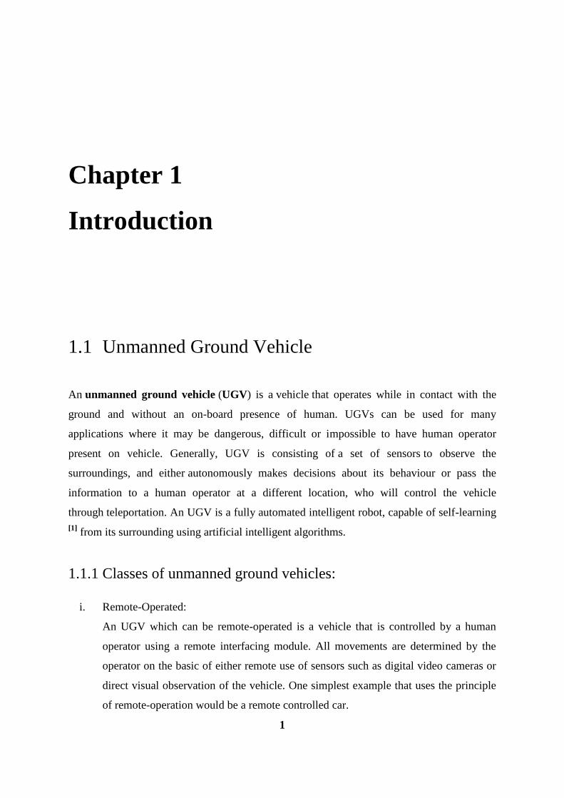
Figure – 14.1: Developed UGV for testing
4
Chapter 2
Hardware Implementation
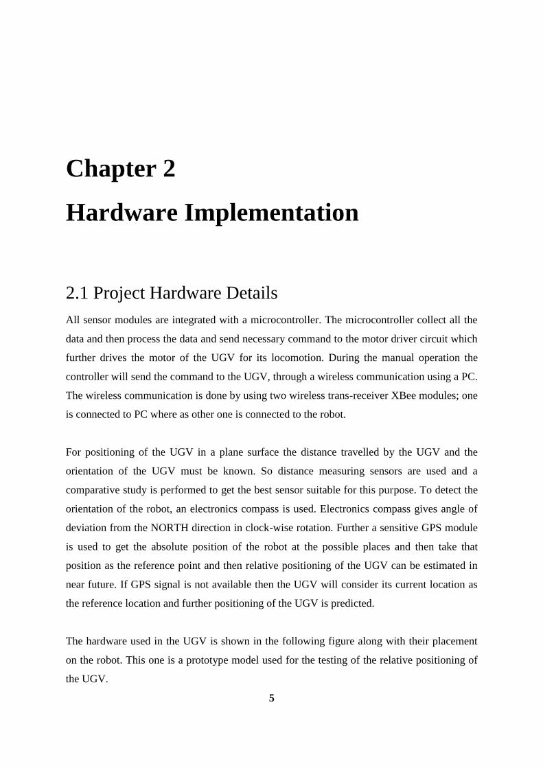
2.1 Project Hardware Details
All sensor modules are integrated with a microcontroller. The microcontroller collect all the
data and then process the data and send necessary command to the motor driver circuit which
further drives the motor of the UGV for its locomotion. During the manual operation the
controller will send the command to the UGV, through a wireless communication using a PC.
The wireless communication is done by using two wireless trans-receiver XBee modules; one
is connected to PC where as other one is connected to the robot.
For positioning of the UGV in a plane surface the distance travelled by the UGV and the
orientation of the UGV must be known. So distance measuring sensors are used and a
comparative study is performed to get the best sensor suitable for this purpose. To detect the
orientation of the robot, an electronics compass is used. Electronics compass gives angle of
deviation from the NORTH direction in clock-wise rotation. Further a sensitive GPS module
is used to get the absolute position of the robot at the possible places and then take that
position as the reference point and then relative positioning of the UGV can be estimated in
near future. If GPS signal is not available then the UGV will consider its current location as
the reference location and further positioning of the UGV is predicted.
The hardware used in the UGV is shown in the following figure along with their placement
on the robot. This one is a prototype model used for the testing of the relative positioning of
the UGV.
5
6
Electronics compass
gives absolute
orientation of the
robot
Provides GPS/INS
data for navigation
and targeting
Data from GPS is
used for absolute
positioning of the
robot
XBee is used for long
range wireless
communication with
the robot from the
remote location
Drive the motors after
getting signal from the
controller
Accelerometer gives
information about the
instantaneous acceleration
Gyro-sensor gives relative
orientation of the robot
GPS
MODULE
ELECTRONIC- COMPASS
SHAFT ENCODER XBee MODULE
MOTOR DRIVER
LI-PO BATTERY
Supply power to
all component
and modules of
the robot.
Process the data
and control the
navigation of UGV
Microcontroller-
Arduino mega 2560
Figure – 2.1: Developed robot used for the testing of positioning
2.2 Component Details
List of components used during the development of the UGV are as follows:
i. GPS (Global Positioning System):
ii. Electric compass
iii. Shaft Encoder
iv. XBee module
v. interfacing base for XBee
vi. motor driver module
vii. microcontroller – Arduino mega 2560
viii. LI-PO battery
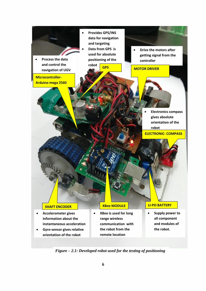
2.2.1 GPS (Global Positioning System) module
GPS module provides a string of data consisting of longitude, latitude, altitude and many
more data related to the position of the module. Here only longitude and latitude values are
collected and processed in the micro-controller and further used for relative positioning.
Figure – 2.2.1: GPS module
7
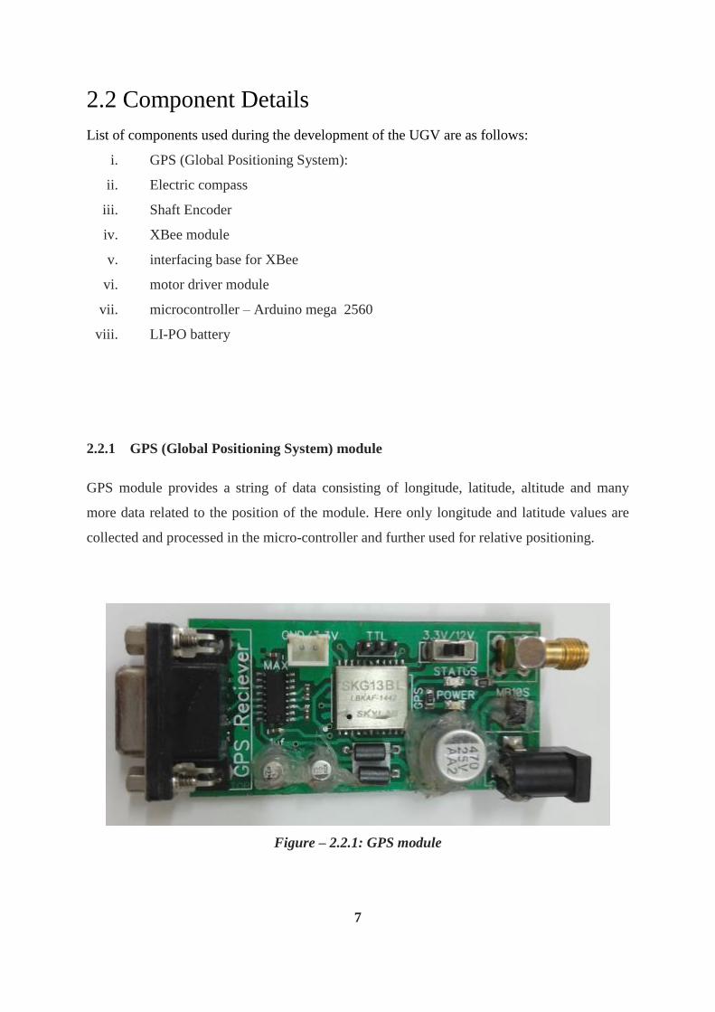
2.2.2 Electronic Compass module
Electronics compass provide the absolute angle of deviation of the robot in degree from
NORTH direction. The angle of deviation is measured in clockwise direction from the
NORTH direction. Performance is high due to integration of solid-state magnetic sensor.
It uses I2C – two wire serial communications with the controller for transmitting angle of
deviation.
Figure – 2.2.2: Electronics Compass Module
2.2.3 Shaft Encoder
Shaft encoder helps in measuring distance covered by the vehicle to calculate the relative
positioning from the starting reference point. It will add more accuracy to the GPS result. It
works on the principle of counting the number of interruption occurred in IR-receiver sensor.
Figure – 2.2.3: Shaft Encoder module
8
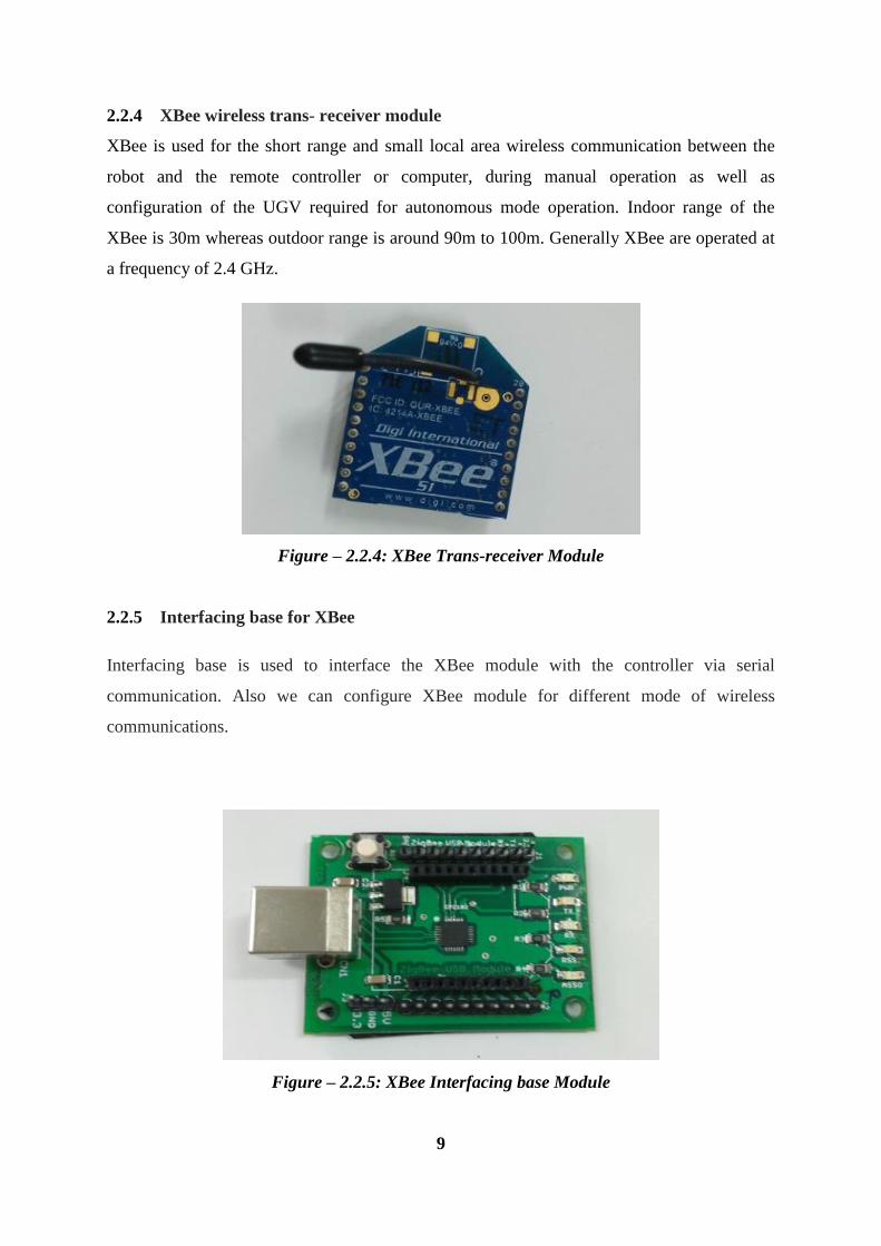
2.2.4 XBee wireless trans- receiver module
XBee is used for the short range and small local area wireless communication between the
robot and the remote controller or computer, during manual operation as well as
configuration of the UGV required for autonomous mode operation. Indoor range of the
XBee is 30m whereas outdoor range is around 90m to 100m. Generally XBee are operated at
a frequency of 2.4 GHz.
Figure – 2.2.4: XBee Trans-receiver Module
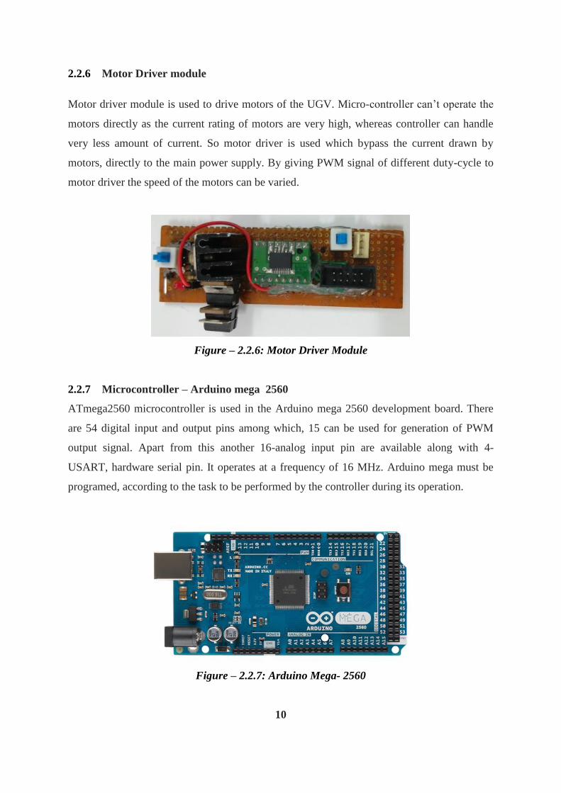
2.2.5 Interfacing base for XBee
Interfacing base is used to interface the XBee module with the controller via serial
communication. Also we can configure XBee module for different mode of wireless
communications.
Figure – 2.2.5: XBee Interfacing base Module
9
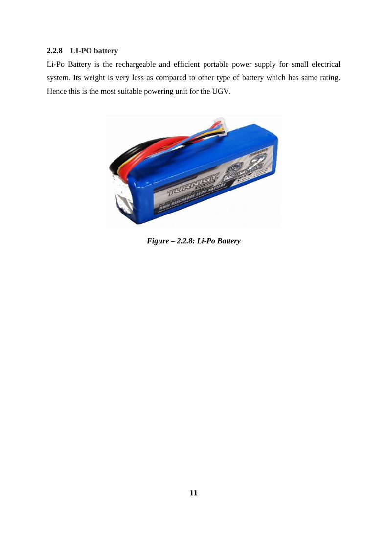
2.2.6 Motor Driver module
Motor driver module is used to drive motors of the UGV. Micro-controller can’t operate the
motors directly as the current rating of motors are very high, whereas controller can handle
very less amount of current. So motor driver is used which bypass the current drawn by
motors, directly to the main power supply. By giving PWM signal of different duty-cycle to
motor driver the speed of the motors can be varied.
Figure – 2.2.6: Motor Driver Module
2.2.7 Microcontroller – Arduino mega 2560
ATmega2560 microcontroller is used in the Arduino mega 2560 development board. There
are 54 digital input and output pins among which, 15 can be used for generation of PWM
output signal. Apart from this another 16-analog input pin are available along with 4-
USART, hardware serial pin. It operates at a frequency of 16 MHz. Arduino mega must be
programed, according to the task to be performed by the controller during its operation.
Figure – 2.2.7: Arduino Mega- 2560
10
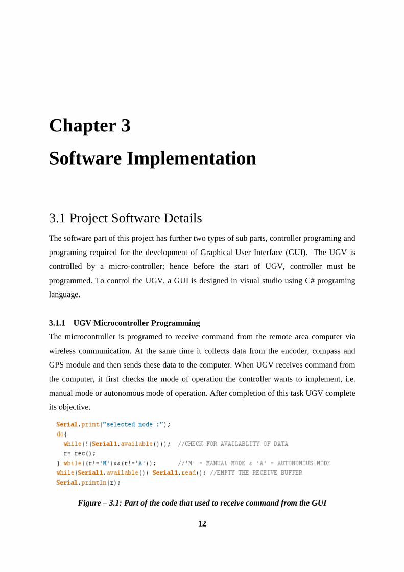
2.2.8 LI-PO battery
Li-Po Battery is the rechargeable and efficient portable power supply for small electrical
system. Its weight is very less as compared to other type of battery which has same rating.
Hence this is the most suitable powering unit for the UGV.
Figure – 2.2.8: Li-Po Battery
11
Chapter 3
Software Implementation
3.1 Project Software Details
The software part of this project has further two types of sub parts, controller programing and
programing required for the development of Graphical User Interface (GUI). The UGV is
controlled by a micro-controller; hence before the start of UGV, controller must be
programmed. To control the UGV, a GUI is designed in visual studio using C# programing
language.
3.1.1 UGV Microcontroller Programming
The microcontroller is programed to receive command from the remote area computer via
wireless communication. At the same time it collects data from the encoder, compass and
GPS module and then sends these data to the computer. When UGV receives command from
the computer, it first checks the mode of operation the controller wants to implement, i.e.
manual mode or autonomous mode of operation. After completion of this task UGV complete
its objective.
Figure – 3.1: Part of the code that used to receive command from the GUI
12
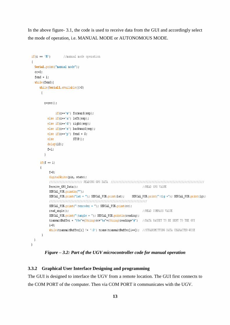
In the above figure- 3.1, the code is used to receive data from the GUI and accordingly select
the mode of operation, i.e. MANUAL MODE or AUTONOMOUS MODE.
Figure – 3.2: Part of the UGV microcontroller code for manual operation
3.3.2 Graphical User Interface Designing and programming
The GUI is designed to interface the UGV from a remote location. The GUI first connects to
the COM PORT of the computer. Then via COM PORT it communicates with the UGV.
13
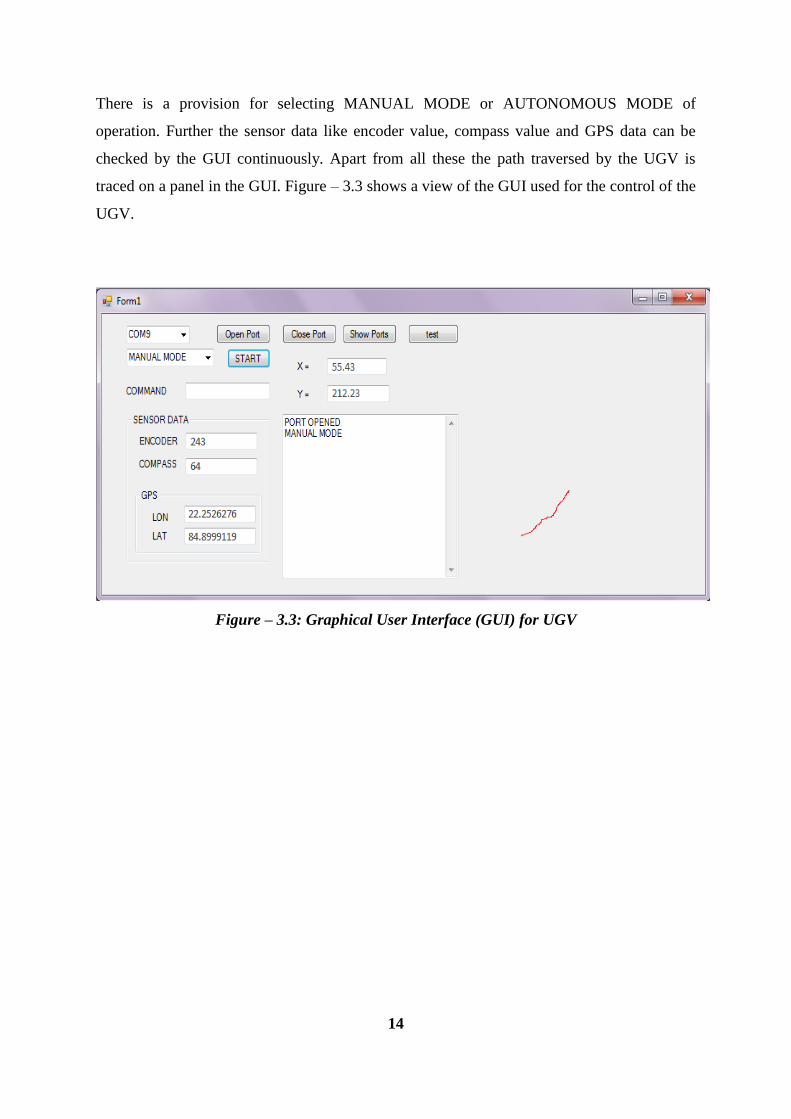
There is a provision for selecting MANUAL MODE or AUTONOMOUS MODE of
operation. Further the sensor data like encoder value, compass value and GPS data can be
checked by the GUI continuously. Apart from all these the path traversed by the UGV is
traced on a panel in the GUI. Figure – 3.3 shows a view of the GUI used for the control of the
UGV.
Figure – 3.3: Graphical User Interface (GUI) for UGV
14
Chapter 4
Work Done
4.1 Working Principle
A robot is designed and used as an UGV to test the positioning technique [6]. Computer
collects all the data from sensors and then processes those data to trace the path of the UGV
during its real-time operation. At each small time interval it measures the change in distance
or distance travelled in a small time interval from its previous position. Along with the
distance travelled the angle of deviation with respect to the NORTH direction is measured
using the electronic compass. After getting the distance travelled and the angle of deviation
we get a relative coordinate in polar notation. This polar form of relative coordinate is
converted to Cartesian coordinate system by using appropriate conversion formula. After
getting the relative Cartesian coordinate, this can be added to the previous absolute
coordinate of the UGV to get the final position.
During MANUAL MODE and AUTONOMOUS MODE of operation the destination of the
UGV is first estimated then the navigation starts. The processor checks at each small interval
of time whether the set destination is reached or not. If destination is not reached then it
continues its motion else it stops its navigation process and completes the task. In the
following sections block diagram of the UGV and flow-chart of the working model is shown
for better understanding about the project.
15
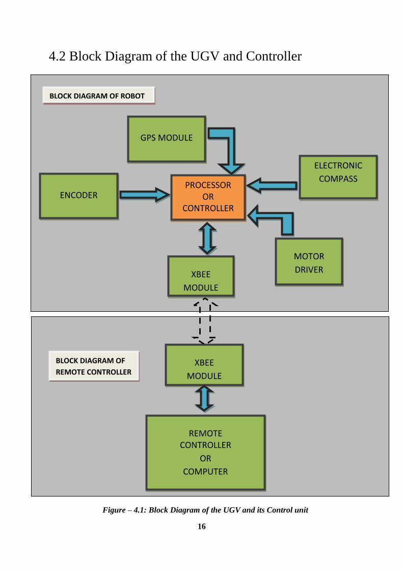
4.2 Block Diagram of the UGV and Controller
16
PROCESSOR OR
CONTROLLER
GPS MODULE
ELECTRONIC
COMPASS
ENCODER
XBEE
MODULE
BLOCK DIAGRAM OF ROBOT
XBEE
MODULE
REMOTE CONTROLLER
OR
COMPUTER
BLOCK DIAGRAM OF
REMOTE CONTROLLER
MOTOR
DRIVER
Figure – 4.1: Block Diagram of the UGV and its Control unit
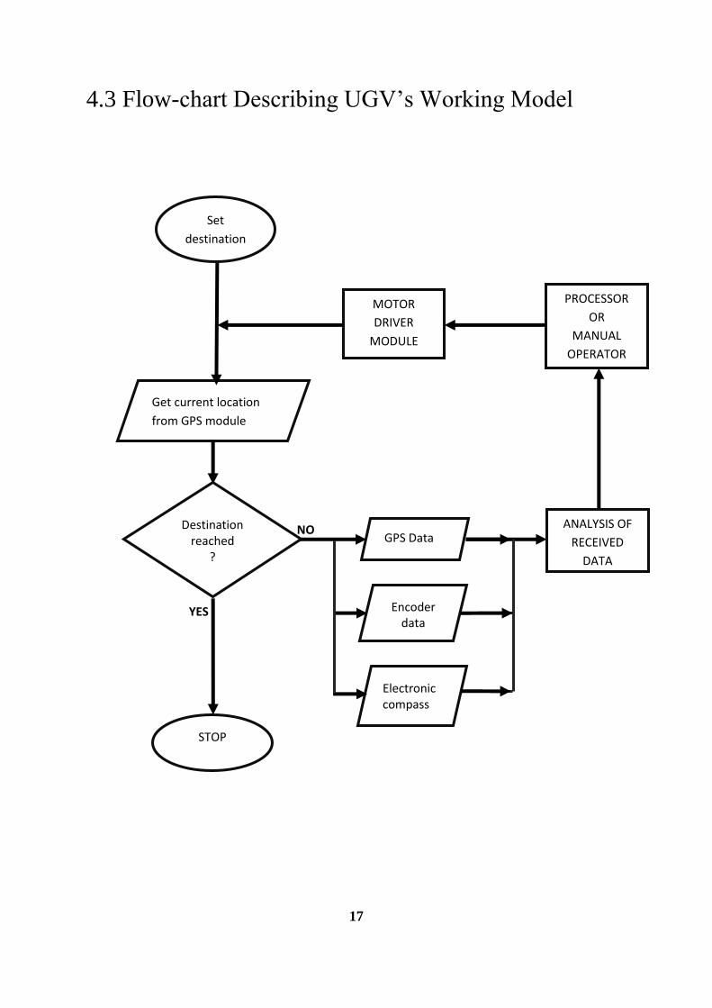
4.3 Flow-chart Describing UGV’s Working Model
17
Get current location
from GPS module
STOP
GPS Data
Encoder data
Electronic compass
NO
YES
PROCESSOR
OR
MANUAL
OPERATOR
MOTOR
DRIVER
MODULE
Set
destination
ANALYSIS OF
RECEIVED
DATA
Destination reached
?
Chapter 5
Conclusion
4.1 Result and Observation
The UGV is designed successfully and its relative position is estimated and also traced on the
GUI. A comparative study is performed during sensor selection for the distance measurement
and it has been found that encoder gives more accurate data regarding the distance travelled
by the UGV as compared to the distance measured using accelerometer. Hence encoder is
preferred over accelerometer for distance measurement.
Since the electronic compass is highly sensitive to magnetic field, compass module must be
placed away from other modules which has magnetic materials; for better and effective angle
measurement.
Finally the relative positioning of the UGV is estimated with very less error which can be
neglected and still the UGV can navigate safely without any fail.
4.2 Future Possibilities
The distance measurement can be more accurate and efficient if both encoder and
accelerometer sensor data are combined together using some good algorithm or any possible
technique. The UGV can be integrated with obstacle detection sensors or Kinect sensor [7] to
detect obstacles and avoid them during its navigation process.
Also the traced path can be saved and used for future navigation at the same location or
nearby surrounding for better and efficient navigation. Further learning algorithm can be used
to increase efficiency of the navigation.
18
References
[1] Wikipedia article on Unmanned Ground Vehicle, http://en.wikipedia.org/wiki/Unman
ned_ground_vehicle, accessed on Oct – 2014.
[2] NYWF. The 1939 New York World’s fair. http://www.1939nyworldsfair.com/worlds
fair/dex.htm accessed on Oct-2014.
[3] D.W. Gage, UGV History 101: A brief history of unmanned ground vehicle (UGV)
development efforts. Unmanned Systems, 13:9–32, 1995.
[4] D.A. Forsyth and J. Ponce. Computer vision: a modern approach. Pearson; 2 edition,
Nov – 2011.
[5] M. Peckham, Time.com article, http://techland.time.com/2012/05/08/googles-
driverless-cars-now-officially-licensed-in-nevada/ accessed on Oct – 2014.
[6] B.J. Yoon, M.W. Park and J.H. Kim, UGV(Unmanned Ground Vehicle) Navigation
Method using GPS and Compass, SICE-ICASE International Joint Conference,3621-
3625, 2006.
[7] A.A. Nayak, D.S. Purniya, G.R. Pradhan, Robotics navigation in the presence of static
and dynamic obstacles, B.Tech. Thesis, NIT Rourkela, 2012.
19
Recommended