DEVELOPMENT OF A FIXED BASE VISUAL APPROACHAND LANDING SIMULATOR
Richard Allen Gibson
mHan


NAVAL POSTGRADUATE SCHOOL
Monterey, California
THESISDEVELOPMENT OF A FIXED BASE VISUAL
APPROACH AND LANDING SIMULATOR
by
Richard Allen Gibson
Thesis Advisor: D. M. Layton
March 1972
Approved fori puhtic. ^teXeose; dlbfyiibuAJLovi unLLmittd.

Development of a Fixed Base Visual
Approach and Landing Simulator
by
Richard Allen GibsonLieutenant, United States Navy
B. S., United States Naval Academy, 1964
Submitted in partial fulfillment of the
requirements for the degree of
MASTER OF SCIENCE IN AERONAUTICAL ENGINEERING
from the
NAVAL POSTGRADUATE SCHOOLMarch 1972

ABSTRACT
A fixed base visual approach and landing simulator was devel-
oped using an F-105 Canopy /Seat Cockpit Trainer, Panasonic Closed
Circuit Television System, and a SMK-22 Main Attachment Unit.
Difficulties encountered in interface of the units necessitated modifi-
cation of the SMK-22 Attachment Unit in both flight characteristics
and operating modes. A main control console was assembled to con-
trol and coordinate the operation of the system elements and monitor
the system during simulated flight. Reduction in degrees of freedom
was achieved through elimination of the yaw mode. An FJ-4 control
stick was modified and installed in the cockpit replacing the fabricated
control stick. Longitudinal trim control was achieved with the trim
switch installed in the FJ-4 control stick, modifying longitudinal cir-
cuitry by means of an additional trim assembly.

TABLE OF CONTENTS
I. INTRODUCTION 4
II. DISCUSSION 6
A. BACKGROUND 6
B. COCKPIT 8
C. SMK-22 10
D. CONTROL CONSOLE 12
in. CONCLUSION 14
A. CAPABILITIES 14
B. LIMITATIONS 14
IV. RECOMMENDATIONS 15
APPENDLX 16
REFERENCES 26
INITIAL DISTRIBUTION LIST 27
FORM DD 1473 28


I. INTRODUCTION
Simulation of aircraft flight is accomplished by employing
techniques varying from the use of digital computers which analyze
proposed aircraft to employment of complete operational flight trainers.
In mathematical simulation, equations of motion combined with individ-
ual aircraft characteristics and environmental conditions are calculated
yielding solutions in the form of printed output.
Pilot training and evaluation, on the other hand, is conducted
through the use of highly complex operational flight trainers which dup-
licate the dynamics of a particular aircraft along with varying environ-
mental conditions. Scientific research must draw on both fields in
order to investigate specific areas of interest. Simulators in this field
must have the capability to simulate various aircraft types and flight
regimes along with a sufficiently sophisticated computer system in
order to obtain realistic results.
The procurement of a U.S. Air Force SMK-22 Visual Simulator
Main Attachment Unit afforded an excellent opportunity to investigate
several areas of current interest in aeronautical research. These
areas include comparison of displacement and force control sticks in
both center and side-arm mounted modes. An additional benefit
obtained from development of the visual flight simulator is its use to
complement the Mini -link Analog Flight Simulator previously developed
at the Naval Postgraduate School.


The purpose of this thesis was to develop and modify, if
necessary, the simulator in order to provide realistic simulation of
the behavior of a single engine jet aircraft in the approach and landing
phase of simulated flight. An additional requirement was to increase
the versatility of the system to accept various types of flight controls.


II. DISCUSSION
A. BACKGROUND
The SMK-22 system was designed to operate with several types
of operational flight trainers including the P3A, C11C and B52.
Through the use of the SMK-22 landing simulator, visual landing and
take-off capability can be combined with simulated operational flight
providing complete flight simulation. The SMK-22 main attachment
unit consists of a belt mechanism, lighting system, television support
mechanism and control panel. It employs servomechanisms for belt
drive, television camera attitude and positioning.
An operational flight trainer was not available to provide input
signals to the landing simulator, therefore a means of signal genera-
tion had to be fabricated that was compatible with the input character-
istics of the main attachment unit. This was accomplished by means
of potentiometer tap-offs from throttle and flight controls mounted in
an F-105 cockpit/seat trainer. Significant problem areas encountered
pertained to matching signal output with attachment unit input restric-
tions in both magnitude and range. In addition it was desired to achieve
control of all the components of the system, vary certain parameters
and monitor the visual display as seen by pilots from one location. To
accomplish this, a control console was assembled, consisting of a tele-
vision repeater, attachment unit controls, and variable d. c. power

supply.
In visual simulation equations of motion, aircraft characteristics
and simulated environmental conditions are processed by a computer,
which provides output signals. These signals can be utilized to drive
cockpit instruments, generate a contact display (projected geometric
patterns representing section lines on the earth's surface), or drive a
camera assembly. The visual presentation furnishes feedback to the
pilot indicating relative aircraft position from which further correc-
tions can be made.
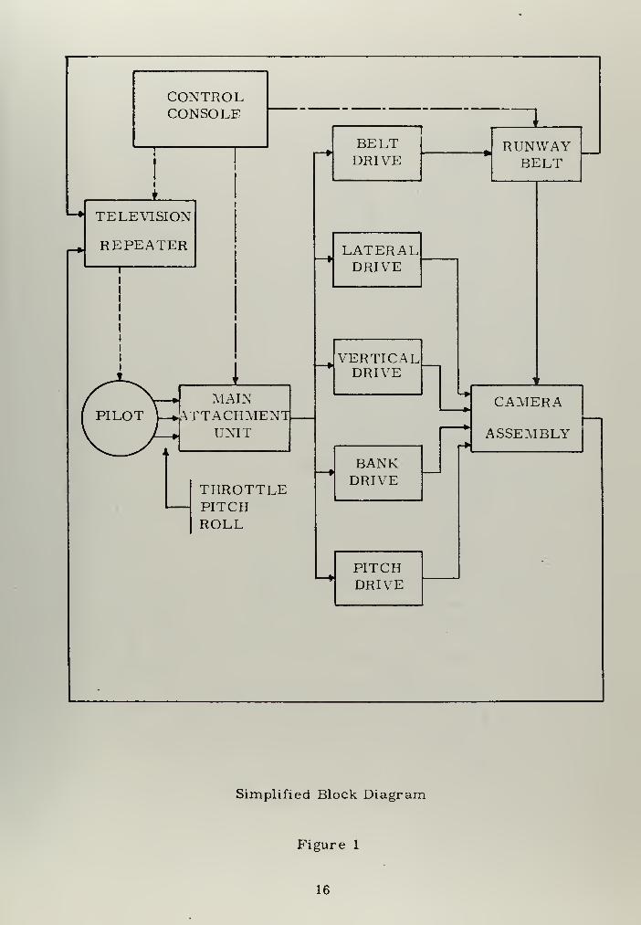
There is no computer section in the SMK-22 main attachment
unit. The fixed base approach and landing simulator system is limited
to receiving signals derived from control deflections and throttle set-
tings. These signals are scaled and combined to drive the runway belt
and camera assembly, which in turn gives the pilot a pictoral presen-
tation of the approach and landing (Figure 1).
Variations for individual aircraft characteristics and flight con-
ditions must be applied electrically at appropriate points in the SMK-22
Control Panel Assembly.
In a limited sense, the SMK-22 functions as an Analog device.
Input signals received are scaled, balanced and amplified in order to
drive the various servomechanisms. Potentiometer feedback tap-offs
on the camera assembly are combined with inputs to provide signals
for lateral rate and altitude.


B. COCKPIT
Difficulties encountered in cockpit utilization were primarily
associated with the original control stick (Figure 4). The magnitude
and range of signal outputs were unacceptable. Lateral movement of
the control stick was insufficient (approximately plus or minus 20°).
The springs utilized in both fore and aft and lateral movement were
compression type. The high breakout forces encountered (2-3 lbs. )
coupled with short angular displacement caused considerable over-
shoot. Reliability of the control stick was poor in that Allen screws
which secured tap-off potentiometers to stick pivot axes kept loosening,
necessitating realignment of the system. The friction of the plastic
bushings was so high that it disguised the stick center position. There
was no provision for including longitudinal trim control on the stick.
The number of shortcomings in the original stick indicated a
definite need for replacement. An FJ-4 Fury control stick assembly
was available, but the base dimensions and gear drive ratios were
inappropriate for direct installation. In order to facilitate its use, the
forward part of the cockpit console was widened, and the stick assembly
(Figure 5) was installed.
An important factor in signal generation is the manner in which
the SMK-22 main attachment unit processes signals. Rates of move-
ment (linear and angular velocity) are essentially fixed. Variation of
these rates over a small range is possible through use of trim poten-
tiometers. Angles of bank and pitch are functions of stick deflections.
8


Roll and descent rates are fixed in a similar manner. This situation
meant constant stick deflection was required to hold an angle of bank
or nose down attitude. The solution to this problem will be discussed
later.
The nature of this characteristic was such that a wide range of
potentiometer travel was required for full bank and pitch. This was
accomplished by changing gear ratios and substituting potentiometers
of lower resistance for both pitch and roll. This eliminated the
"jittering" effect of the potentiometer wiper arm traveling through
small angular displacements over a few turns of resistor wire. The
physical aspects of the FJ-4 stick include:
+ 35° roll
+ 25° pitch
4° nose-up to 8° nose down trim variation
1. 1 pounds -per -inch pitch
1.0 pounds-per-inch roll
Friction is negligible. Tension can be easily increased by mounting
additional springs at base of assembly.
The need for constant stick displacement for constant pitch angle
was eliminated by including the capability of longitudinal trim control.
It was necessary to fabricate a switching device which adjusted this
constant deflection signal to various pitch angles. The assembly uses
a motor driven potentiometer to furnish a constant pitch signal. The
trim switch in the FJ-4 stick was connected to the assembly which was


mounted in the left-hand console bay. The trim position is varied by
energizing the potentiometer drive through the stick trim switch,
changing the value of the basic pitch signal (Figure 2).
The remaining constant signal-deflection requirement, that of
roll, was eliminated by disconnecting the feedback signal from the roll
potentiometer tap-off mounted on the camera assembly.
Instrumentation in the cockpit consists of an altimeter, airspeed
indicator, remote closed circuit television repeater, and flight-path
deviation-indicator ID-249 (Figure 6).
C. SMK-22
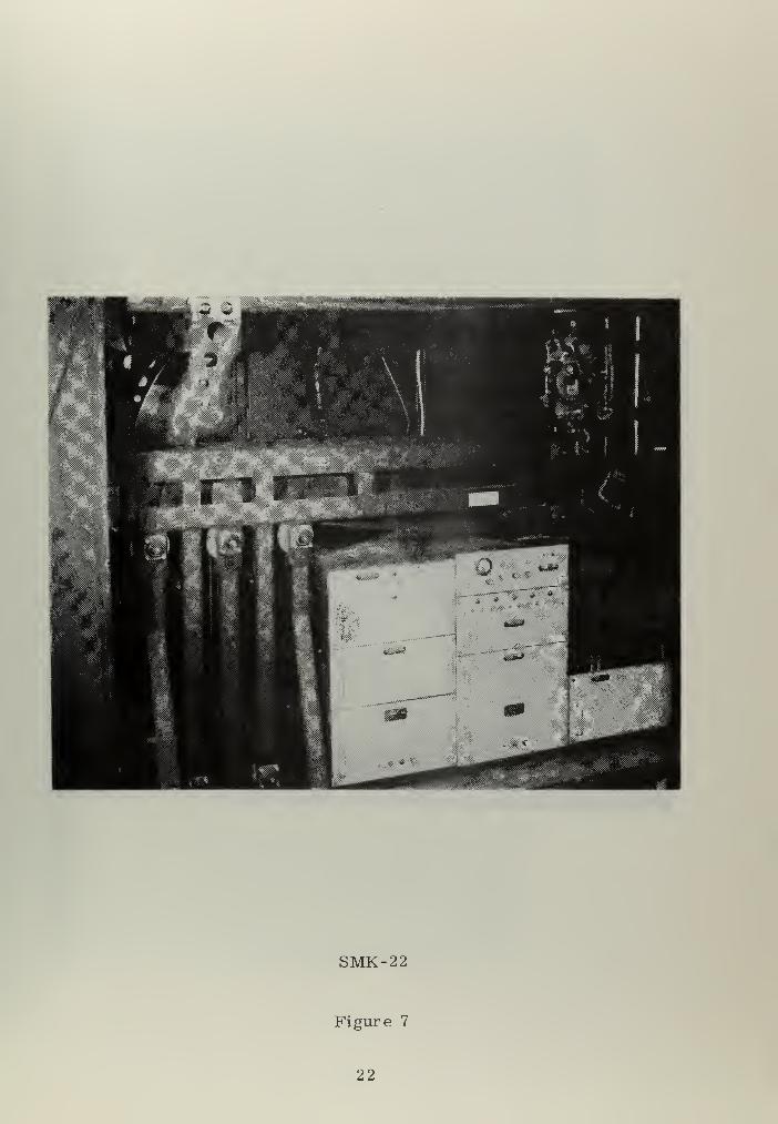
The main attachment unit (Figure 7) presented several difficulties.
The major area requiring modification was the vertical mode of the
camera assembly. The altitude that the camera assembly assumes is a
function of voltage. Approach began at a relatively low altitude of 600
feet above the runway. In addition the rate of descent or climb is vir-
tually fixed (variable over small margin by trim potentiometer on con-
trol assembly). The rate of closure to runway is altered by varying the
throttle setting, thereby adjusting the airspeed and relative rate of
closure. An additional limitation to operation of the main attachment
unit was the inability of the camera assembly to pass through the nose
level position, in other words, stop a rate of descent and commence
climbing. This limitation was due to the use of alternating current for
signal output and servomechanism drives. There was no capability to
reset the camera assembly at rates of climb other than 500-700 feet-
10

per-minute. This required long delays between runs.
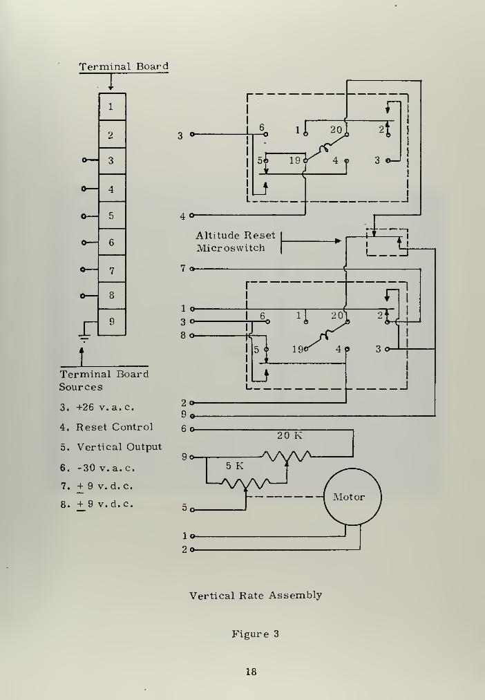
The limitations of slow altitude reset and inability to climb and
descend in the same run were eliminated through the use of a fabrica-
ted vertical rate assembly (Figure 3). The assembly uses relays
which adjust range of motion of the camera assembly as it passes
through the nose level position (Figure 8).
Fast reset was accomplished through the use of a motor driven
potentiometer which increases the altitude voltage at a high rate. An
additional feature was included in the vertical rate assembly which
automatically resets the camera assembly as soon as a landing is
made.
The descent rate trim potentiometer was replaced with a ten turn
potentiometer and moved to the control unit. A manual altitude reset
control was added to the main attachment unit and also mounted on the
control unit.
Operation of the camera assembly was hampered by high azimuth
rate. Roll input signal yielded excessive rates of turn of the camera
assembly. In addition, interference from the ultraviolet lamps used to
illuminate phosphor coated runway lights caused 15° yaw excursions to
right whenever these lights were energized. Inclusion of a 1000 ohm
variable potentiometer in series with azimuth rate servomotor to
attain acceptable rates of turn was unsuccessful. The resulting reduced
voltage caused a hesitating motion in azimuth rate. At this time the
decision was made to freeze yawing motion of the camera assembly.
11

Changes in the visual presentation were considered to be negligible,
inasmuch as a pilot does not fix his eyes to the aircraft's longitudinal
axis but rather focuses his attention on the landing area during an
approach. The major visual input therefore is lateral motion with
respect to the runway center line. In this respect, the frozen azimuth
of the camera assembly duplicates the function of the pilot's eyes. In
flying the simulator in this configuration, it was found that lateral
motion combined with rate of closure and yielded apparent motion in a
direction several degrees to the right or left of center line.
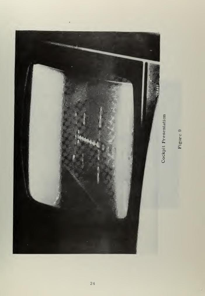
The television camera proved to be highly sensitive to available
light. The visual presentation with the main attachment unit doors
secured and ultraviolet light energized was so detailed that the runway
belt and belt track were visible (Figure 9). A polarized filter was
mounted on the camera lens thereby masking all but the landing lights
and strobe.
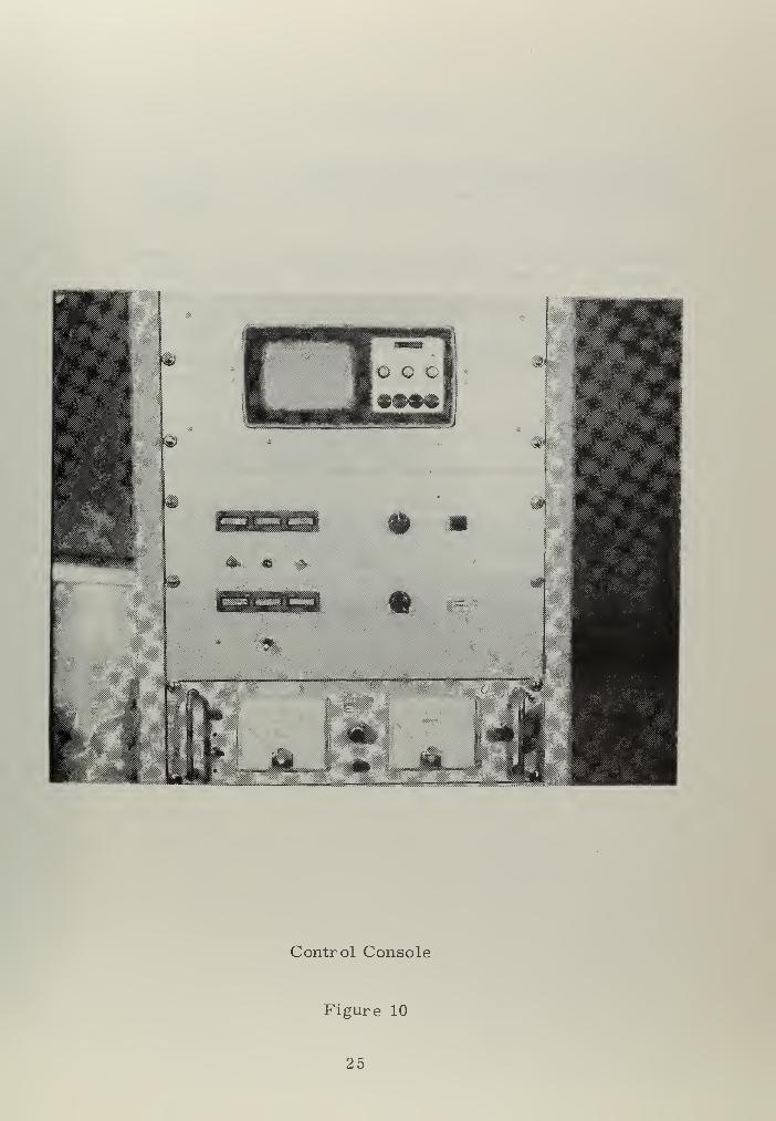
D. CONTROL CONSOLE
To facilitate control and monitor operation of the system, the
original control console was reconstructed and mounted in a vertical
equipment cabinet (Figure 10). The components of the console consist
of a Sony television, variable d.c. power supply, SMK-22 Main Attach-
ment Unit function controls, and main circuit breaker.
Included in the attachment unit section of the console are the
emergency power cut-off switch, visibility limitation filter adjustment
control, and rate of climb/descent control.
12


The variable d.c. power supply was used to power the longitudi'
nal trim and vertical rate assemblies.
13


m. CONCLUSIONS
A. CAPABILITIES
The goal of this thesis project was accomplished. The fixed-
base visual approach and landing simulator closely duplicates the
motion of a jet aircraft in the landing configuration. Elimination of
the azimuth mode does not significantly degrade the performance of
the system. The physical characteristics of the FJ-4 stick are
reasonably realistic. Approaches flown in the simulator can be
aborted and climbs commenced.
B. LIMITATIONS
Rate of descent remains fixed for the pilot. Operation of the
flight-path deviation-indicator horizontal needle begins at 500 feet
indicated altitude, although approach commences at 600 feet. Stick
force is somewhat low and its motion is undamped.
14

IV. RECOMMENDATIONS
It is recommended that evaluation of flight controls be initiated
using the FJ-4 stick. Preliminary designs of a side-mounted displace-
ment stick have been considered prior to termination of this thesis
project. It is anticipated that significant areas in fabrication of the
side stick will involve choice of springs, type of linkage, gear ratios
and signal scaling.
A highly feasible future use of the simulator system would be its
conversion to an aircraft carrier landing simulator by marking a flight
deck on the rubber belt. A minor landing aid can be produced with
fiber optics.
15

CONTROLCONSOLE
!'
BELTDRIVE
RUNWAYBELT
i i
—
•—*
TELEVISION
REPEATER—
*
LATERALDRIVE
^jL i '
— VERTICALDRIVE
V
Cpilot^
MAINATTACHMENT
UNIT
CAMERA
ASSEMBLYfei>
—
y i
— BANKDRIVE
i
THROTTLEPITCHROLL
PITCHDRIVE
Simplified Block Diagram
Figure 1
16


Terminal Board
_L*
9 v. d. c.
o
—
V
1
2
3
4
5
6
7
8
6 7
Q
3 o
5 oTrim Switchj-
8 o-
2 o-
3 o-
—
o
Nose-up
Nose-downL I
+30 v. a. c. o
©Output o—
30 v.a.c. o-
8.9 yv
AAAAVV\A/
1 KSl
Longitudinal Trim Assembly
Figure 2
17

Terminal Board
1
2
— 3
— 4
5
— 6
— 7
*- 8
r 9
tTerminal BoardSources
3. +26 v. a.c.
4. Reset Control
5. Vertical Output
6. -30 v. a. c.
7. + 9 v. d. c.
8. + 9 v. d. c.
3 °-
40-
Altitude ResetMicroswitch
7 o-
1 o-
3 o-
80-
20-
9«-
Vertical Rate Assembly
Figure 3
18


#
Stick
Figure 4
19


FJ-4 Stick
Figure 5
20


IH
Instrument Panel
Figure 6
21

SMK-22
Figure 7
22


Vertical Rate Assembly
Figure 8
23

05
Cud1-1
24

'^«i»0O>»M-»
Control Console
Figure 10
25


REFERENCES
1. Armstrong, B. D. , Difficulties with the Simulation of AircraftLandings , Royal Aircraft Establishment, Great Britain, May1968.
2. Connelly, M.E., Simulation of Aircraft, U.S. Naval TrainingDevices Center, Cambridge 39, Massachusetts, February1958.
3. Kraft, J.N., A Visual Approach and Landing Simulator System ,
Master of Science Thesis, Naval Postgraduate School,
Monterey, California, September 1971.
4. Mulhern, J. J., The Physical and Functional Characteristics of
Flight Control Systems Simulators , U.S. Naval Air Develop-ment Center, Johnsville, Pennsylvania, April 1959.
5. Perry, D.H., Warton, C.H. , Welbourn, C.E., A Flight Simula -
tor for Research into Aircraft Handling Characteristics,
Royal Aircraft Establishment, Great Britain, December 1968.
6. U.S. Air Force Technical Manual T.O. 43X20-2-1, Operation-Maintenance Trainer Attachment, Visual Simulator SMK-22/F37A-T, Air Force DPSU, August 1966.
26


INITIAL DISTRIBUTION LIST
No. Copies
1. Defense Documentation Center 2
Cameron Station
Alexandria, Virginia 22314
2. Library, Code 0212 2
Naval Postgraduate School
Monterey, California 93940
3. Chairman, Department of Aeronautics 1
Naval Postgraduate School
Monterey, California 93940
4. Professor Donald M. Layton 1
Department of Aeronautics
Naval Postgraduate School
Monterey, California 93940
5. LT Richard Allen Gibson, USN 1
1260 Spruance RoadMonterey, California 93940
27

UnclassifiedSecurity Classification
DOCUMENT CONTROL DATA -R&D{Security etas si fie ation of title, body of abstract and indexing annotation must be entered when the overall report is classified)
I . ORIGINATING ACTIVITY (Corporate author)
Naval Postgraduate School
Monterey, California 93940
2a. REPORT SECURITY CLASSIFICATION
Unclassified26. CROUP
Open3. REPORT TITLE
Development of a Fixed Base Visual Approach and Landing Simulator
4 descriptive NOTES (Type of report and, inclusive dates)
Masters Thesis; March 19725 AUTHOR(S) (First name, middle initial, last name)
Richard Allen Gibson
8. REPORT DATE 7a. TOTAL NO. OF PAGES
March 1972 29
7b. NO. OF REFS
8a. CONTRACT OR GRANT NO.
6. PROJEC T NO.
9«. ORIGINATOR'S REPORT NUMBER'S)
96. OTHER REPORT NOISI (Any other numbers that may be aaslgned(hit report)
10. DISTRIBUTION STATEMENT
Approved for public release; distribution unlimited.
II. SUPPLEMENTARY NOTES 12. SPONSORING MILITARY ACTIVITY
Naval Postgraduate SchoolMonterey, California 93940
13. ABSTRAC T
A fixed base visual approach and landing simulator was devel-
oped using an F-105 Canopy /Seat Cockpit Trainer, Panasonic ClosedCircuit Television System, and a SMK-22 Main Attachment Unit.
Difficulties encountered in interface of the units necessitated modi-fication of the SMK-22 Attachment Unit in both flight characteristics
and operating modes. A main control console was assembled to con-
trol and coordinate the operation of the system elements and monitor
the system during simulated flight. Reduction in degrees of freedomwas achieved through elimination of the yaw mode. An FJ-4 control
stick was modified and installed in the cockpit replacing the fabricated
control stick. Longitudinal trim control was achieved with the trim
switch installed in the FJ-4 control stick, modifying longitudinal cir-
cuitry by means of an additional trim assembly.
DD, Fr:..1473 <PAGE "
S/N 0101 -807-681 128
UnclassifiedSecurity Classification
A- 3 1408


UnclassifiedSecurity Classification
KEY WO R OS
Flight simulator
Landing simulator
Approach simulator
Visual simulator
>D ,
F° R.\,1473 (BACK)
1 OtOt -807-6821
HO L E w T
29UnclassifiedSecurity Classification A- 3 I 409


rhes i s
/
G3?6 Gfbso,
134479
Development of a ,base visual f '*e
landfnq sfIfPPr°ach
'"9 simulator.
-ru •134479
Thesis
G396 Gibsonc.l Development of a fixed
base visual approachlanding simulator.

thesG396
Development of a fixed base visual appro
3 2768 002 02874 8DUDLEY KNOX LIBRARY
Recommended