Development of Low Cost Industrially
Scalable PCM Capsules for Thermal
Energy Storage in CSP Plants
D. Yogi Goswami, Ph.D, PE
Distinguished University Professor
Director, Clean Energy Research Center
University of South Florida, Tampa, FL 33620
Start Date – December 2011

2
APPROACH
Use low cost, high temperature PCMs with uniquely tailored heat
transfer characteristics for overcoming the problem of low thermal
conductivity of PCMs for fast charging and discharging
Optically active PCMs and shell linings for enhanced heat transfer
Use electroless deposition techniques for encapsulating the porous PCM
pellets to form capsules of required size and shape
Layer -2: Encapsulating layer
Layer -1: Thin layer with high emittance
PCM pellet with tailored radiative properties
Develop very low cost industrially scalable capsules of
PCMs for utility scale TES for CSP plants operating at
3000C to 10000C
Development Goal and Approach
3
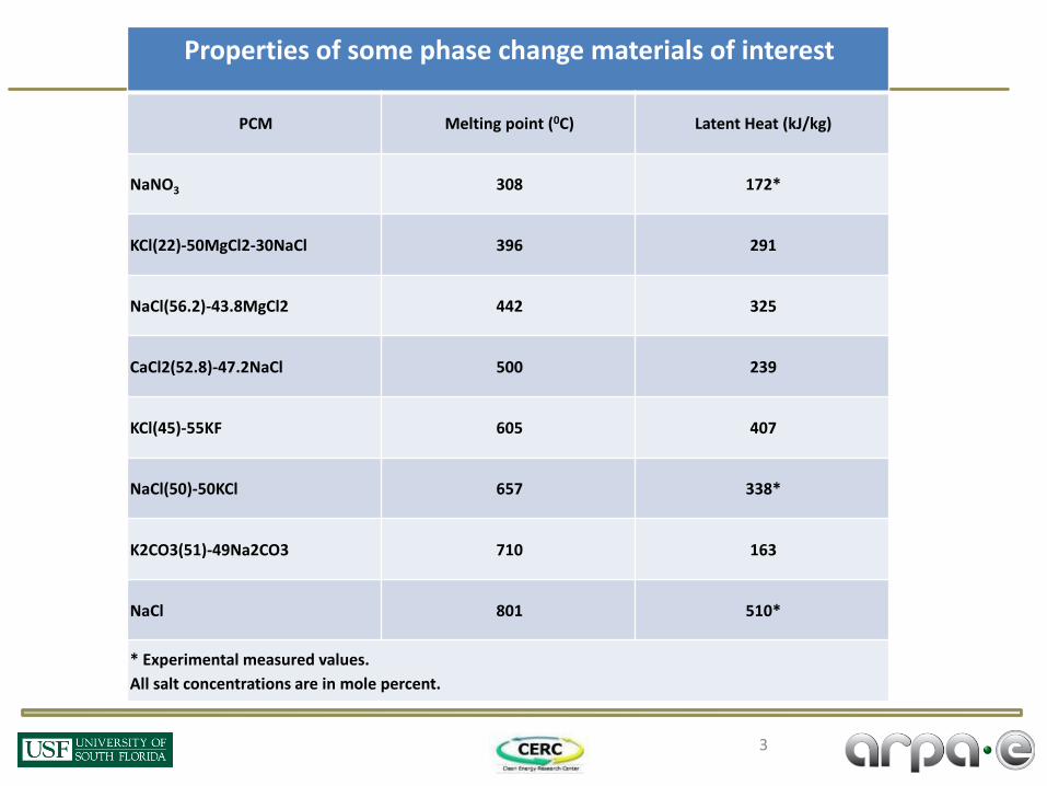
Properties of some phase change materials of interest
PCM Melting point (0C) Latent Heat (kJ/kg)
NaNO3 308 172*
KCl(22)-50MgCl2-30NaCl 396 291
NaCl(56.2)-43.8MgCl2 442 325
CaCl2(52.8)-47.2NaCl 500 239
KCl(45)-55KF 605 407
NaCl(50)-50KCl 657 338*
K2CO3(51)-49Na2CO3 710 163
NaCl 801 510*
* Experimental measured values.
All salt concentrations are in mole percent.

Encapsulation of PCM pellets (300 – 4000C)
Precoating – A layer is coated around the salt pellet
The pre-coat is metallized using electroless and electroplating chemistry
Final PCM Capsule for
300 – 4000 C range Capsule after 1500 Thermal
Cycles ~ 5 years equivalent

Characterization of PCMs
No of cycles passed
Melting point Tm (o C)
Heat of Fusion (j/g)
0 307.2 170.2
59 306.82 170.6
154 308.15 170.3
700 306.56 170.7
1000 307.47 170.6
0 Cycle
59 Cycles
154 Cycles
700 cycles
1000 Cycles
307.47
306.56
308.15
306.82
307.2

Development of Coating Procedures for 600–10000C Capsules
Two methods are being developed the High Temperature PCMs
Final encapsulated PCM Pre-formed ceramic shells
The first method involves the Use of preformed
ceramic shells.

Development of Coating Procedures for 600–10000C Capsules
The second method involves direct ceramic coating
on the salt pellet
NaCl capsule coated
with the ceramic
Thermal testing was done on the capsules at 805oC. The pellet was cut open to
check for leakage of salt into the pores of the ceramic layer.
Intact salt capsule
after thermal testing Cut portion of the
capsule
Development of Coating Procedures
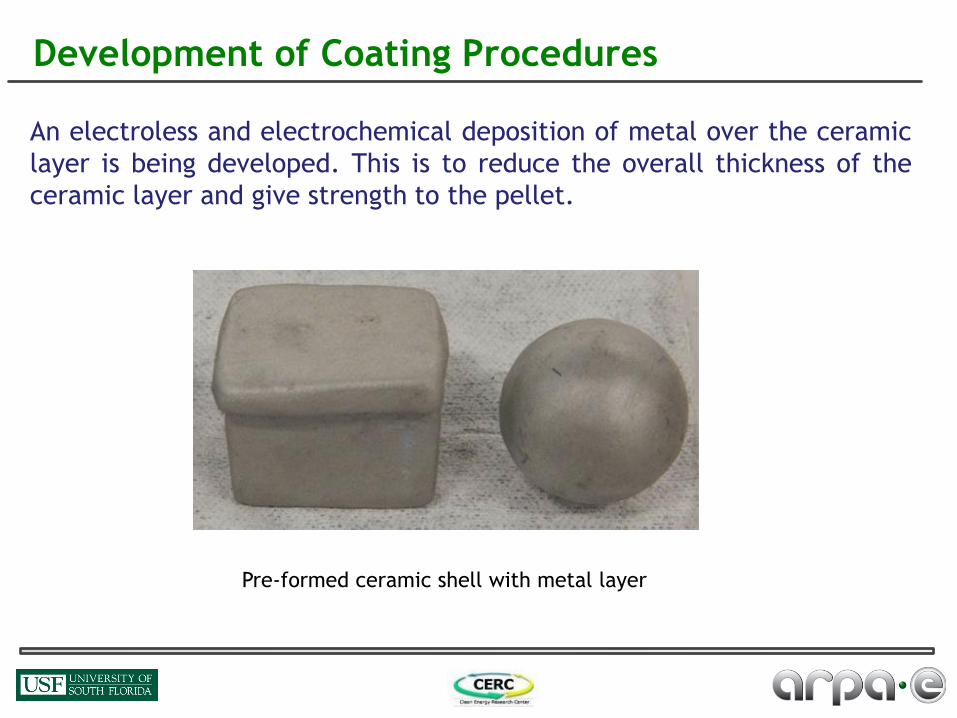
An electroless and electrochemical deposition of metal over the ceramic
layer is being developed. This is to reduce the overall thickness of the
ceramic layer and give strength to the pellet.
Pre-formed ceramic shell with metal layer

9
Demonstration of Improved Radiative Heat Transfer
Nano-scale additive attenuates radiation in the infrared region (left fig.)
DSC demonstrates improved heat transfer in KCl-NaCl eutectic.
Small concentration (0.3 wt %) yields pronounced increase in heat
flow rate (right fig. vertical axis).
Shift in peaks suggests accelerated melt time.
Pure Eutectic
- - - - Eutectic w/additive

10
Demonstration of Improved Radiative Heat Transfer
695
700
705
710
715
720
725
730
735
740
745
750
755
760
0.00 1.00 2.00 3.00 4.00 5.00 6.00 7.00 8.00 9.00
Tem
pe
ratu
re (
⁰C)
Avg. Time (min.)
Temperature Vs. Avg. Time Graph
Pure NaCl
NaCl+Addtive

11
Characterization of the PCMs
Latent Heat of the chosen PCMs (NaCl and 50%NaCl-50%KCl
eutectic) were measured using TA Instruments DSC-TGA (see
eutectic endotherm below)
DHfus (NaCl) = 509.91 J/g DHfus (eutectic) = 337.6 J/g

Cyclic Testing and Evaluation of the PCM Pellets
High temperature capsules are undergoing heating and cooling cycles.
Optimization of ceramic composition and thickness is in progress.
850 oC
The pellet was cut open to check the diffusion of
the salt into the ceramic layer

Post-coating Thermal
treatment (IR Heater)
Electroless coating involving a series of sub-processing steps
Screw Feeder for PCM powder
Homogenizer/Mixer/ Vibrating Shaker/ Hopper
Conveyor belt for carrying uniform size powder
Mesh at the bottom for the flow of uniform size particle distribution
Production of pellets in Rotary press
Pre-coating Thermal treatment (Surface preparation before coating)
Coating on PCM in impaction blending dry particle coating machine
1
2
3 4
5 6 7
Important quality control steps required during each subsequent processing steps: 1) Monitoring or a continuous flow through feeder 2) Particle size distribution; Quality of mixing
3) Size; Strength; Weight loss 4) Thermal cycling of PCM
8
Electroplating involving a series of sub-processing steps
Manufacturing Process Layout
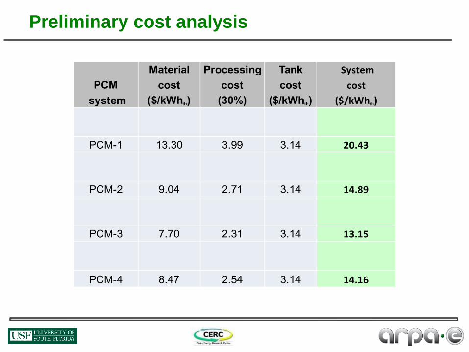
Preliminary cost analysis

Numerical Results
A spherical shell, is entirely filled with the solid NaCl at Ti =797.7 oC. For time t>0, a constant temperature
boundary condition Tw (10, 15 and 20 oC above the NaCl melting temperature, 800.7 oC) is applied on the
outer surface of the shell. Fig. 1 shows the schematic of the system
The PCM is treated as a semitransparent medium where thermal radiation can be emitted and absorbed.
Physical properties are presented in Table 1.
Property NaCl
𝐷𝑒𝑛𝑠𝑖𝑡𝑦 (𝑘𝑔/𝑚3)
solid phase 2160
mushy zone 325858.7 − 302𝑇
Liquid phase 2139.3 − 0.543𝑇
𝜌𝑙 (𝑘𝑔/𝑚3) 1556
𝐷𝑦𝑛𝑎𝑚𝑖𝑐 𝑣𝑖𝑠𝑐𝑜𝑠𝑖𝑡𝑦 (𝑘𝑔/𝑚 𝑠) 1.01𝑥10−3
𝐿𝑎𝑡𝑒𝑛𝑡 ℎ𝑒𝑎𝑡 𝑜𝑓 𝑓𝑢𝑠𝑖𝑜𝑛 (𝐽/𝑘𝑔) 479289
𝑀𝑒𝑙𝑡𝑖𝑛𝑔 𝑡𝑒𝑚𝑝𝑒𝑟𝑎𝑡𝑢𝑟𝑒 (℃) 800.7
𝑆𝑝𝑒𝑐𝑖𝑓𝑖𝑐 ℎ𝑒𝑎𝑡 (𝐽/𝑘𝑔𝐾) 1200
𝑇ℎ𝑒𝑟𝑚𝑎𝑙 𝑐𝑜𝑛𝑑𝑢𝑐𝑡𝑖𝑣𝑖𝑡𝑦 (𝑊/𝑚𝐾) 0.7
Fig. 1 System schematic. Table1. Thermo-physical properties.

Different study cases have been analyzed for a 15mm inner radius capsule in order to asses the effects of
the wall temperature and absorption coefficient (ka) on the thermal performance of the system. All of them
are summarized in Table 2. Table2. Study cases.
Case Tw - Tm (ºC) GrR Ste ka(m-1
) Pr
1 10 2.75x10⁵ 0.025
1.74 2 15 4.12x10⁵ 0.037 100
3 20 5.48x10⁵ 0.050
4 20 5.48x10⁵ 0.050 20
1.74 5 10 2.75x10
5 0.025 0
Numerical Results
A number of non-dimensional quantities and parameters can be defined to characterize the heat
transfer and the phase change process at high temperatures. Those are:
𝑃𝑟 =𝜈
𝛼
𝑃𝑙 =𝑘(𝜅𝑎 + 𝜅𝑠)
4𝜎𝑇03
𝑇0 =𝑇𝑤 + 𝑇𝑚
2
𝐺𝑟 =𝑔𝛽 𝑇𝑤 − 𝑇𝑚 𝑅𝑖
3
𝜈2
𝑆𝑡𝑒 =𝐶𝑝 𝑇𝑤 − 𝑇𝑚
𝐿 𝛼 =
𝑘
𝜌𝑐𝑝
𝑅𝑖 = 𝑠ℎ𝑒𝑙𝑙 𝑖𝑛𝑛𝑒𝑟 𝑟𝑎𝑑𝑖𝑢𝑠
𝛽 = 𝑡ℎ𝑒𝑟𝑚𝑎𝑙 𝑒𝑥𝑝𝑎𝑛𝑠𝑖𝑜𝑛 𝑐𝑜𝑒𝑓𝑓.
𝜈 = 𝐾𝑖𝑛𝑒𝑚𝑎𝑡𝑖𝑐 𝑣𝑖𝑠𝑐𝑜𝑠𝑖𝑡𝑦
∝ = 𝑡ℎ𝑒𝑟𝑚𝑎𝑙 𝑑𝑖𝑓𝑓𝑢𝑠𝑖𝑣𝑖𝑡𝑦
𝜌 = 𝐷𝑒𝑛𝑠𝑖𝑡𝑦
𝑘 = 𝑇ℎ𝑒𝑟𝑚𝑎𝑙 𝑐𝑜𝑛𝑑𝑢𝑐𝑡𝑖𝑣𝑖𝑡𝑦
𝜎 = 𝑆𝑡𝑒𝑓𝑎𝑛 − 𝐵𝑜𝑙𝑡𝑧𝑚𝑎𝑛𝑛 𝑐𝑡𝑛.
𝜅𝑎 = 𝑎𝑏𝑠𝑜𝑟𝑝𝑡𝑖𝑜𝑛 𝑐𝑜𝑒𝑓𝑓𝑖𝑐𝑖𝑒𝑛𝑡
𝜅𝑠 = 𝑠𝑐𝑎𝑡𝑡𝑒𝑟𝑖𝑛𝑔 𝑐𝑜𝑒𝑓𝑓𝑖𝑐𝑖𝑒𝑛𝑡
𝜃 = 𝑑𝑖𝑚𝑒𝑛𝑠𝑖𝑜𝑛𝑙𝑒𝑠𝑠 𝑡𝑒𝑚𝑝.
𝑇0 = 𝑟𝑒𝑓𝑒𝑟𝑒𝑛𝑐𝑒 𝑡𝑒𝑚𝑝.
𝐺𝑟 = 𝐺𝑟𝑎𝑠ℎ𝑜𝑓 𝑛𝑢𝑚𝑏𝑒𝑟
𝑃𝑙 = 𝑃𝑙𝑎𝑛𝑐𝑘 𝑛𝑢𝑚𝑏𝑒𝑟
𝑃𝑟 = 𝑃𝑟𝑎𝑛𝑑𝑡𝑙 𝑛𝑢𝑚𝑏𝑒𝑟
𝑆𝑡𝑒 = 𝑆𝑡𝑒𝑓𝑎𝑛 𝑛𝑢𝑚𝑏𝑒𝑟
𝑔 = 𝑔𝑟𝑎𝑣𝑖𝑡𝑦
𝑐𝑝 = 𝑠𝑝𝑒𝑐𝑖𝑓𝑖𝑐 ℎ𝑒𝑎𝑡
𝐿 = 𝑙𝑎𝑡𝑒𝑛𝑡 ℎ𝑒𝑎𝑡
t = 10s t = 40s t = 80s
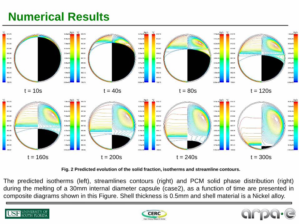
The predicted isotherms (left), streamlines contours (right) and PCM solid phase distribution (right)
during the melting of a 30mm internal diameter capsule (case2), as a function of time are presented in
composite diagrams shown in this Figure. Shell thickness is 0.5mm and shell material is a Nickel alloy.
t = 120s
t = 160s t = 200s t = 240s t = 300s
Fig. 2 Predicted evolution of the solid fraction, isotherms and streamline contours.
Numerical Results
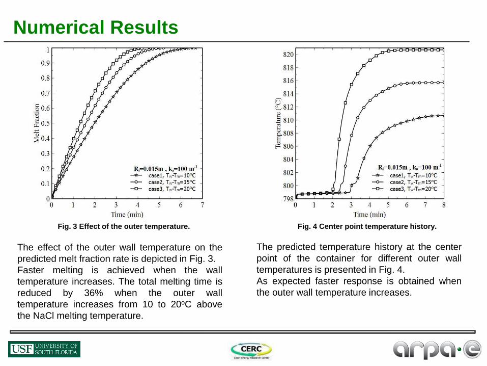
The predicted temperature history at the center
point of the container for different outer wall
temperatures is presented in Fig. 4.
As expected faster response is obtained when
the outer wall temperature increases.
The effect of the outer wall temperature on the
predicted melt fraction rate is depicted in Fig. 3.
Faster melting is achieved when the wall
temperature increases. The total melting time is
reduced by 36% when the outer wall
temperature increases from 10 to 20oC above
the NaCl melting temperature.
Fig. 3 Effect of the outer temperature. Fig. 4 Center point temperature history.
Numerical Results

The predicted melt fraction rate for study cases 1
and 5 are presented in fig. 5.
Faster melting is observed in the case where
NaCl is treated as an absorbing and emitting
medium. The total melting time is reduced by
35% when the absorption coefficient increases
from 0 to 100m-1
The effect of the absorption coefficient (ka) on the
predicted melt fraction rate is shown in Fig. 6.
Faster melting is achieved when the absorption
coefficient is higher.
Fig. 5 Melt fraction rate for cases 1 and 5. Fig. 6 Effect of the absorption coefficient.
Numerical Results

Fig. 8. Time history at shown location. Fig. 7. Schematic of the system.
Vertical cylindrical container (Fig. 7) is initially filled with solid NaCl at 700°C. For time t>0 a constant
temperature boundary condition (Tw=760°C) is imposed at the outer surface of the wall.
The transient diffusion-controlled heat transfer is analyzed. The numerically predicted and the experimentally
measured temperature history at 19mm above the bottom surface of the container is presented in Fig.8.
The numerically predicted time history shows a good agreement with experimental results.
L=
71
mm
Ro=26.5mm
Solid NaCl
Nickel Axis of symmetry 0
22mm
3mm
Numerical Results

Numerical Results
Melt Fraction rate
correlation.
Dimensionless Nusselt
number
Validation
case
𝑀𝐹 = 1 − 1 −𝐹𝑜𝑆𝑡𝑒0.33𝐺𝑟𝑅
0.25
3
2.23
[7] 𝑁𝑢𝑆𝑡𝑒0.62
𝐺𝑟𝑅0.25 =
0.345𝑒𝑥𝑝 −5.75𝜉3.25 + sin 0.068 + 0.55𝜉 , 0.04 ≤ 𝜉 < 0.4
0.57𝑒𝑥𝑝 −0.36𝜉1.9 , 0.4 ≤ 𝜉 ≤ 3.0
[8]
Correlations valid in the range encompassing the cases simulated:
0.047 < Ste < 0.104, 1.28 x 10⁴ < GrR < 2.0 x 10⁵, Pr = 9.1.
[2] Assis E, Katsman L, Ziskind G, Letan R. Numerical and experimental study of melting in a spherical shell. Int J Heat Mass Transfer 2007; 50: pp.
1790–1804.

Conclusions
• Successfully developed PCM capsules with provision for
expansion/contraction during melting/freezing
• Characterized the PCMs of interest
• Tested capsules for thermal cycling Completed 1500 cycles (continuing) for 300 – 4000C
Capsules for 600 – 10000C being optimized for cyclic performance
• Developed a numerical model for melting/solidification
• Developed a manufacturing plan for capsules
• Cost estimate of a TES system based on the developed
PCM capsules – $13.15/kWhth (<< than goal of $20)

FUTURE WORK
• Optimization of ceramics coatings for encapsulation
• Continuation of Thermal cyclic testing of capsules
• Development of a numerical model for System Design
• Continuation of Characterization of PCMs and
Capsules
• Testing in a lab scale TES system

Thank You
Recommended