12/3/2013
1
University of Ioannina - Department of Computer Science
Christophoros Nikou
Images taken from: R. Gonzalez and R. Woods. Digital Image Processing, Prentice Hall, 2008
Digital Image Processing
Morphological Image Processing
2
C. Nikou – Digital Image Processing
Morphological Image Processing
and Analysis
In form and feature, face and limb,
I grew so like my brother,
That folks got taking me for him
And each for one another.
Henry Sambrooke Leigh,
Carols of Cockayne, The Twins
3
C. Nikou – Digital Image Processing
Contents
Mathematical morphology provides tools for
the representation and description of image
regions (e.g. boundary extraction, skeleton,
convex hull).
It provides techniques for pre- and post-
processing of an image (morphological
thinning, pruning, filtering).
Its principles are based on set theory.
Applications to both binary and graylevel
images.
4
C. Nikou – Digital Image Processing
Preliminaries
The four horizontal and vertical neighbours of
a pixel p are called 4-neighbours of p and are
denoted by N4(p).
The four diagonal neighbours of a pixel p are
denoted by ND(p).
Together N4(p) and ND(p) are called the 8-
neighbours of pixel p and are denoted by
N8(p).
5
C. Nikou – Digital Image Processing
Preliminaries (cont.)
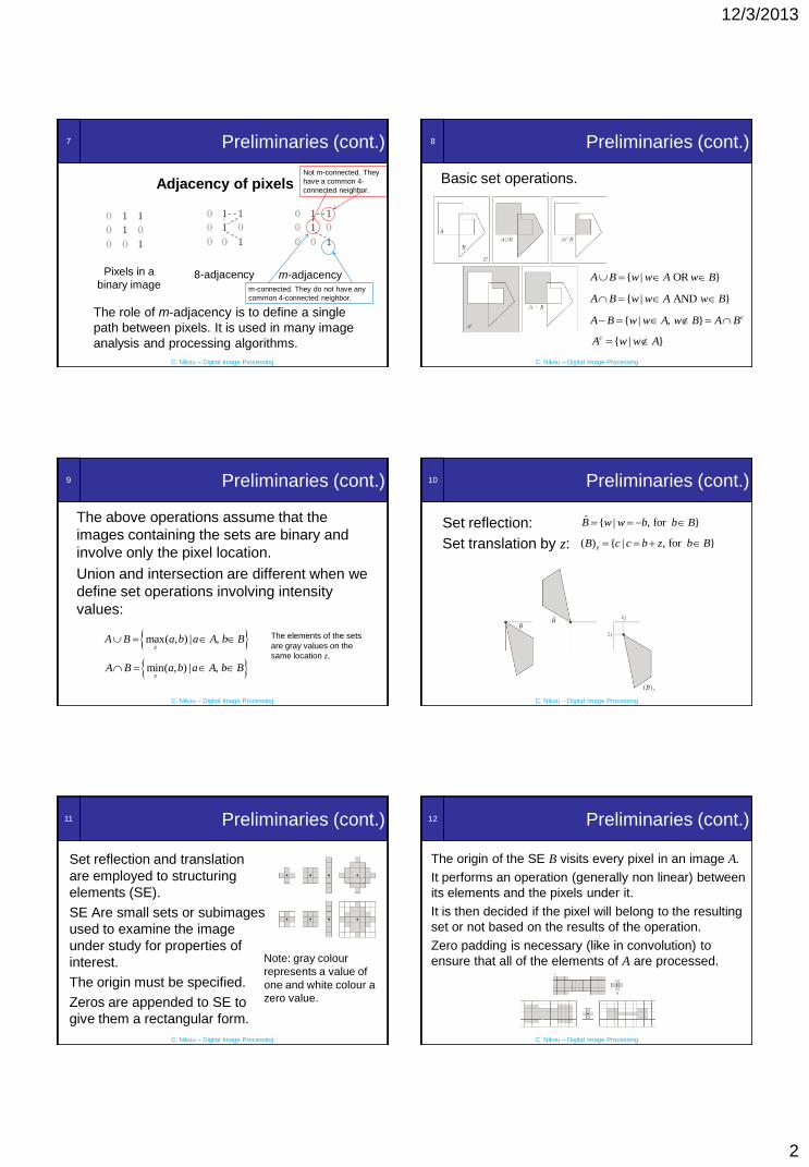
Adjacency of pixels
Let V be the set of intensity values used to
define the adjacency (e.g. V={1} for binary
images).
4-adjacency. Two pixels p and q with values in
V are 4-adjacent if q is in N4(p).
8-adjacency. Two pixels p and q with values in
V are 8-adjacent if q is in N8(p).
6
C. Nikou – Digital Image Processing
Preliminaries (cont.)
Adjacency of pixels
m-adjacency (mixed adjacency). Two pixels p
and q with values in V are m-adjacent if
• q is in N4(p), or
• q is in ND(p) and the set N4(p) ∩ N4(q) has
no pixels whose values are in V .
Mixed adjacency is a modification of the 8-
adjacency. It is introduced to eliminate
ambiguities of 8-adjacency.
12/3/2013
2
7
C. Nikou – Digital Image Processing
Preliminaries (cont.)
Pixels in a
binary image8-adjacency m-adjacency
Adjacency of pixels
The role of m-adjacency is to define a single
path between pixels. It is used in many image
analysis and processing algorithms.
Not m-connected. They
have a common 4-
connected neighbor.
m-connected. They do not have any
common 4-connected neighbor.
8
C. Nikou – Digital Image Processing
Preliminaries (cont.)
Basic set operations.
{ | }cA w w A
{ | , } cA B w w A w B A B
{ | OR }A B w w A w B
{ | AND }A B w w A w B
9
C. Nikou – Digital Image Processing
Preliminaries (cont.)
The above operations assume that the
images containing the sets are binary and
involve only the pixel location.
Union and intersection are different when we
define set operations involving intensity
values:
max( , ) | ,z
A B a b a A b B The elements of the sets
are gray values on the
same location z.
min( , ) | ,z
A B a b a A b B
10
C. Nikou – Digital Image Processing
Preliminaries (cont.)
Set reflection: ˆ { | , for }B w w b b B
( ) { | , for }zB c c b z b B Set translation by z:
11
C. Nikou – Digital Image Processing
Preliminaries (cont.)
Set reflection and translation
are employed to structuring
elements (SE).
SE Are small sets or subimages
used to examine the image
under study for properties of
interest.
The origin must be specified.
Zeros are appended to SE to
give them a rectangular form.
Note: gray colour
represents a value of
one and white colour a
zero value.
12
C. Nikou – Digital Image Processing
Preliminaries (cont.)
The origin of the SE B visits every pixel in an image A.
It performs an operation (generally non linear) between
its elements and the pixels under it.
It is then decided if the pixel will belong to the resulting
set or not based on the results of the operation.
Zero padding is necessary (like in convolution) to
ensure that all of the elements of A are processed.

12/3/2013
3
13
C. Nikou – Digital Image Processing
Preliminaries (cont.)
For example, it marks the pixel under its center
as belonging to the result if B is completely
contained in A (A2, B2).
14
C. Nikou – Digital Image Processing
Morphological Operations
• Some basic operations
– Erosion.
– Dilation.
– Opening.
– Closing.
• Applications
– Morphological filtering.
– The hit-or-miss transformation.
15
C. Nikou – Digital Image Processing
Erosion
The erosion of a set A by a SE B is defined as
The result is the set of all points z such that B
translated by z is contained in A.
Equivalently:
{ | ( ) }zA B z B A
{ | ( ) }c
zA B z B A
16
C. Nikou – Digital Image Processing
Erosion (cont.)
Erosion is a shrinking operation
17
C. Nikou – Digital Image Processing
Erosion (cont.) 18
C. Nikou – Digital Image Processing
Erosion (cont.)
11x11
Erosion by a square SE of varying size
45x4515x15
Original image

12/3/2013
4
19
C. Nikou – Digital Image Processing
Erosion (cont.)
Erosion can split apart joined objects
Erosion can strip away extrusions
Watch out: Erosion shrinks objects
20
C. Nikou – Digital Image Processing
Dilation
The dilation of a set A by a SE B is defined as
The result is the set of all points z such that the
reflected B translated overlap with A at at least
one element.
Equivalently:
ˆ{ | ( ) }zA B z B A
ˆ{ |[( ) ] }zA B z B A A
21
C. Nikou – Digital Image Processing
Dilation (cont.)
Dilation is a thickening operation
22
C. Nikou – Digital Image Processing
Dilation (cont.)
Dilation bridges gaps.
Contrary to low pass filtering it produces a binary image.
23
C. Nikou – Digital Image Processing
Dilation (cont.)
Dilation can repair breaks
Dilation can repair intrusions
Watch out: Dilation enlarges objects
24
C. Nikou – Digital Image Processing
Duality
Erosion and dilation are dual operations with
respect to set complementation and reflection:
Also,
The duality is useful when the SE is symmetric:
The erosion of an image is the dilation of its
background.
ˆ( )c cA B A B
ˆ( )c cA B A B
12/3/2013
5
25
C. Nikou – Digital Image Processing
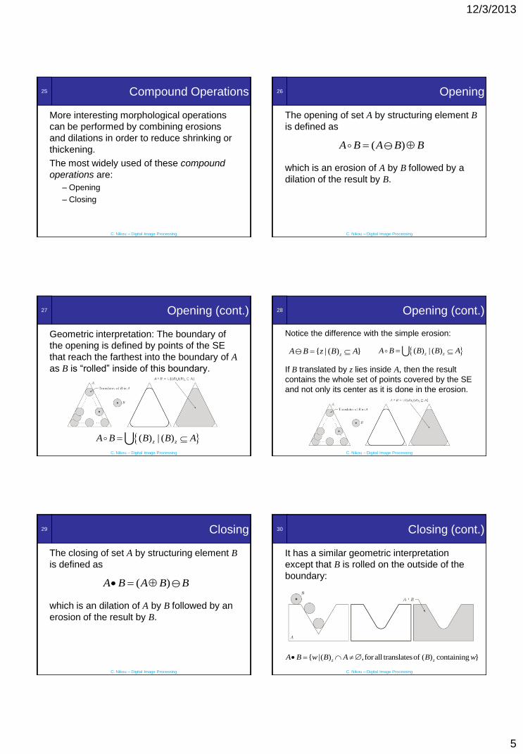
Compound Operations
More interesting morphological operations
can be performed by combining erosions
and dilations in order to reduce shrinking or
thickening.
The most widely used of these compound
operations are:
– Opening
– Closing
26
C. Nikou – Digital Image Processing
Opening
The opening of set A by structuring element B
is defined as
which is an erosion of A by B followed by a
dilation of the result by B.
( )A B A B B
27
C. Nikou – Digital Image Processing
Opening (cont.)
Geometric interpretation: The boundary of
the opening is defined by points of the SE
that reach the farthest into the boundary of A
as B is “rolled” inside of this boundary.
( ) | ( )z zA B B B A
28
C. Nikou – Digital Image Processing
Opening (cont.)
Notice the difference with the simple erosion:
If B translated by z lies inside A, then the result
contains the whole set of points covered by the SE
and not only its center as it is done in the erosion.
( ) | ( )z zA B B B A { | ( ) }zA B z B A
29
C. Nikou – Digital Image Processing
Closing
The closing of set A by structuring element B
is defined as
which is an dilation of A by B followed by an
erosion of the result by B.
( )A B A B B
30
C. Nikou – Digital Image Processing
Closing (cont.)
It has a similar geometric interpretation
except that B is rolled on the outside of the
boundary:
{ |( ) ,for all translatesof ( ) containing }z zA B w B A B w
12/3/2013
6
31
C. Nikou – Digital Image Processing
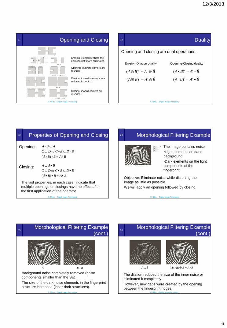
Opening and Closing
Erosion: elements where the
disk can not fit are eliminated.
Opening: outward corners are
rounded.
Closing: inward corners are
rounded.
Dilation: inward intrusions are
reduced in depth.
32
C. Nikou – Digital Image Processing
Duality
Opening and closing are dual operations.
ˆ( )c cA B A B
ˆ( )c cA B A B
ˆ( )c cA B A B
ˆ( )c cA B A B
Erosion-Dilation duality Opening-Closing duality
33
C. Nikou – Digital Image Processing
Properties of Opening and Closing
Opening:
( )
A B A
C D C B D B
A B B A B
Closing:
( )
A A B
C D C B D B
A B B A B
The last properties, in each case, indicate that
multiple openings or closings have no effect after
the first application of the operator
34
C. Nikou – Digital Image Processing
Morphological Filtering Example
Objective: Eliminate noise while distorting the
image as little as possible.
We will apply an opening followed by closing.
The image contains noise:
•Light elements on dark
background.
•Dark elements on the light
components of the
fingerprint.
35
C. Nikou – Digital Image Processing
Morphological Filtering Example
(cont.)
Background noise completely removed (noise
components smaller than the SE).
The size of the dark noise elements in the fingerprint
structure increased (inner dark structures).
A BA
36
C. Nikou – Digital Image Processing
Morphological Filtering Example
(cont.)
The dilation reduced the size of the inner noise or
eliminated it completely.
However, new gaps were created by the opening
between the fingerprint ridges.
( )A B B A B A B

12/3/2013
7
37
C. Nikou – Digital Image Processing
Morphological Filtering Example
(cont.)
The dilation reduces the new gaps between the
ridges but it also thickens the ridges.
A B BA B
38
C. Nikou – Digital Image Processing
Morphological Filtering Example
(cont.)
The final erosion (resulting to a closing of the
opened image) makes the ridges thinner.
[ ] ( )A B B B A B B A B B
39
C. Nikou – Digital Image Processing
Morphological Filtering Example
(cont.)
The final result is clean of noise but some ridges were
not fully repaired.
We should impose conditions for maintaining the
connectivity (we will see a more advanced algorithm).
( )A B BA
40
C. Nikou – Digital Image Processing
The Hit-or-Miss Transformation
Basic tool for shape detection.
Erosion of A by B: the set of all locations of the
origin of B that B is completely contained in A.
Alternatively, it is the set of all locations that B
found a match (hit) in A.
41
C. Nikou – Digital Image Processing
The Hit-or-Miss Transformation
(cont.)
There are many possible locations for the shape
we search (the SE!). If we are looking for disjoint
(disconnected) shapes it is natural to assume a
background for it.
Therefore, we seek to match B in A and
simultaneously we seek to match the background
of B in Ac.
Mathematically, the hit-or-miss transformation is:
* ( ) ( )c
bA B A B A B
42
C. Nikou – Digital Image Processing
The Hit-or-Miss Transformation
(cont.)
We seek to locate the shape
D in the image A.
We define a thin background
W for the shape.
We take the intersection of
the two results
* ( ) ( )cA D A D A W D

12/3/2013
8
43
C. Nikou – Digital Image Processing
Morphological Algorithms
Using these morphological operations we may
extract image components for shape representation:
• Shape boundaries.
• Region filling.
• Connected components
• Convex hull.
• Shape thinning and thickening.
• Skeletons.
We may also accomplish a morphological image
reconstruction.
44
C. Nikou – Digital Image Processing
Boundary Extraction
The boundary of a set A, denoted by β(A),
may be obtained by:
( ) ( )A A A B
45
C. Nikou – Digital Image Processing
Boundary Extraction (cont.)
The boundary is one pixel thick due to the
3x3 SE. Other SE would result in thicker
boundaries.
Original Image Extracted Boundary
46
C. Nikou – Digital Image Processing
Region Filling
Given a pixel inside a boundary, region
filling attempts to fill the area surrounded by
that boundary with 1s.
Given a point inside
here, can we fill the
whole circle?
47
C. Nikou – Digital Image Processing
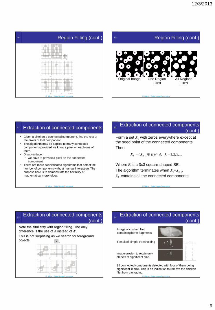
Region Filling (cont.)
Form a set X0 with zeros everywhere except
at the seed point of the region.
Then,
Where B is a 3x3 cross-shaped SE.
The algorithm terminates when Xk=Xk-1.
The set union of Xk and A contains all the
filled holes and their boundaries.
1( ) , 1,2,3,...c
k kX X B A k
48
C. Nikou – Digital Image Processing
Region Filling (cont.)
This is a first example where the morphological
operation (dilation) is conditioned.
The intersection of the result with Ac limits the
result inside the region of interest.
1( ) , 1,2,3,...c
k kX X B A k
12/3/2013
9
49
C. Nikou – Digital Image Processing
Region Filling (cont.) 50
C. Nikou – Digital Image Processing
Region Filling (cont.)
Original Image One Region
Filled
All Regions
Filled
51
C. Nikou – Digital Image Processing
Extraction of connected components
• Given a pixel on a connected component, find the rest of
the pixels of that component.
• The algorithm may be applied to many connected
components provided we know a pixel on each one of
them.
• Disadvantage:
• we have to provide a pixel on the connected
component.
• There are more sophisticated algorithms that detect the
number of components without manual interaction. The
purpose here is to demonstrate the flexibility of
mathematical morphology.
52
C. Nikou – Digital Image Processing
Extraction of connected components
(cont.)
Form a set X0 with zeros everywhere except at
the seed point of the connected components.
Then,
Where B is a 3x3 square-shaped SE.
The algorithm terminates when Xk=Xk-1.
Xk contains all the connected components.
1( ) , 1,2,3,...k kX X B A k
53
C. Nikou – Digital Image Processing
Extraction of connected components
(cont.)
Note the similarity with region filling. The only
difference is the use of A instead of Ac.
This is not surprising as we search for foreground
objects.
54
C. Nikou – Digital Image Processing
Extraction of connected components
(cont.)
15 connected components detected with four of them being
significant in size. This is an indication to remove the chicken
filet from packaging.
Image of chicken filet
containing bone fragments
Result of simple thresholding
Image erosion to retain only
objects of significant size.
12/3/2013
10
55
C. Nikou – Digital Image Processing
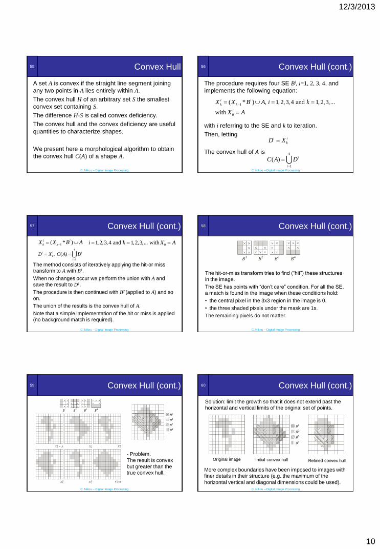
Convex Hull
A set A is convex if the straight line segment joining
any two points in A lies entirely within A.
The convex hull H of an arbitrary set S the smallest
convex set containing S.
The difference H-S is called convex deficiency.
The convex hull and the convex deficiency are useful
quantities to characterize shapes.
We present here a morphological algorithm to obtain
the convex hull C(A) of a shape A.
56
C. Nikou – Digital Image Processing
Convex Hull (cont.)
The procedure requires four SE Bi, i=1, 2, 3, 4, and
implements the following equation:
with i referring to the SE and k to iteration.
Then, letting
The convex hull of A is
1
0
( * ) , 1,2,3,4 and 1,2,3,...
with
i i
k k
i
X X B A i k
X A
i i
kD X
4
1
( ) i
i
C A D
57
C. Nikou – Digital Image Processing
Convex Hull (cont.)
The method consists of iteratively applying the hit-or miss
transform to A with B1.
When no changes occur we perform the union with A and
save the result to D1.
The procedure is then continued with B2 (applied to A) and so
on.
The union of the results is the convex hull of A.
Note that a simple implementation of the hit or miss is applied
(no background match is required).
4
1
, ( )i i i
k
i
D X C A D
01,2,3,4 and 1,2,3,... with ii k X A 1( * )i i
k kX X B A
58
C. Nikou – Digital Image Processing
Convex Hull (cont.)
The hit-or-miss transform tries to find (“hit”) these structures
in the image.
The SE has points with “don’t care” condition. For all the SE,
a match is found in the image when these conditions hold:
• the central pixel in the 3x3 region in the image is 0.
• the three shaded pixels under the mask are 1s.
The remaining pixels do not matter.
59
C. Nikou – Digital Image Processing
Convex Hull (cont.)
- Problem.
The result is convex
but greater than the
true convex hull.
60
C. Nikou – Digital Image Processing
Convex Hull (cont.)
Solution: limit the growth so that it does not extend past the
horizontal and vertical limits of the original set of points.
Original image
More complex boundaries have been imposed to images with
finer details in their structure (e.g. the maximum of the
horizontal vertical and diagonal dimensions could be used).
Initial convex hull Refined convex hull

12/3/2013
11
61
C. Nikou – Digital Image Processing
Thinning
The thinning of a set A, by a SE B may be
defined in terms of the hit-or-miss transform:
( * ) ( * ) cA B A A B A A B
No background match is required and the hit-
or-miss part is reduced to simple erosion.
A more advanced expression is based on a
sequence of SE1 2 3{ } { , , ,..., },nB B B B B
where each Bi is a rotated version of Bi-1.
62
C. Nikou – Digital Image Processing
Thinning (cont.)
The thinning by a sequence of SE is defined by:
The process is to thin A by one pass by B1,
then thin the result with one pass of B2, and
so on, until we employ Bn.
The entire process is repeated until no further
changes occur. Each individual thinning is
performed by:( * )A B A A B
1 2{ } ((...(( ) )...) )nA B A B B B
63
C. Nikou – Digital Image Processing
Thinning (cont.)
• No change between the
result of B7 and B8 at the
first pass.
• No change between the
results of B1, B2, B3, B4 at
the second pass.
• No change occurs after
the second pass by B6 .
•The final result is
converted to
m-connectivity to have a
one pixel thick structure.
64
C. Nikou – Digital Image Processing
Thickening
Thickening is a morphological dual of thinning:
( * )A B A A B
The SE have the same form as the ones used
for thinning with the 1s and 0s interchanged.
It may also be defined by a sequence of
operations:
1 2{ } ((...(( ) )...) )nA B A B B B
65
C. Nikou – Digital Image Processing
Thickening (cont.)
In practice, a separate algorithm is seldom used for
thickening.
The usual process is to thin the background of the
set in question and then take the complement of the
result.
The advantage is that the thinned background forms
a boundary for the thickening process. Direct
implementation of thickening has no stopping
criterion.
A disadvantage is that there may be isolated points
needing post-processing.
66
C. Nikou – Digital Image Processing
Thickening (cont.)
Original set A Ac
Thinning of Ac
Thickened set
obtained by
complementing the
result of thinning.
Elimination of disconnected points.

12/3/2013
12
67
C. Nikou – Digital Image Processing
Skeletons
The notion of a skeleton S(A) of a
set A, intuitively, has the following
properties:
• If z is a point belonging to S(A)
and (D)z is the largest disk
centered at z and contained in A:
one cannot find a larger disk (not
necessarily centered at z)
containing (D)z and included in A.
• (D)z is then called maximum disk.
• The maximum disk touches the
boundary of A at two or more
different points.
68
C. Nikou – Digital Image Processing
Skeletons (cont.)
It may be shown that a definition of the skeleton
may be given in terms of erosions and openings:
0
( ) ( ), with ( ) ( ) ( )K
k k
k
S A S A S A A kB A kB B
successive erosions
with ( ) ((...( ) ) ...) )
k
A kB A B B B
K is the last iterative step before A erodes to an
empty set:
max{ | }K k A kb
69
C. Nikou – Digital Image Processing
Skeletons (cont.)
The previous formulation allows the iterative
reconstruction of A from the sets forming its
skeleton by:
0
( ) ,K
k
k
A S A kB
successive dilations of the set ( )
with ( ) ((...( ( ) ) ) ...) )
k
k k
k S A
S A B S A B B B
70
C. Nikou – Digital Image Processing
Skeletons (cont.)
The skeleton is
• thicker than essential.
• disconnected.
The morphological
formulation does not
guarantee connectivity.
More assumptions are
needed to obtain a
maximally thin and
connected skeleton.
71
C. Nikou – Digital Image Processing
Morphological Reconstruction
• The morphological algorithms discussed so
far involve an image and a SE.
• Morphological reconstruction involves two
images and a SE.
– The marker image containing the starting
point of the transformation.
– The mask image, which constraints the
transformation.
– The SE is used to define connectivity.
72
C. Nikou – Digital Image Processing
Morphological Reconstruction (cont.)
The geodesic dilation of size 1 of a marker image
F by a SE B, with respect to a mask image G is
defined by:(1) ( ) ( )GD F F B G
Similarly, the geodesic dilation of size n is defined by:
( ) (1) ( 1)( ) ( )n n
G G GD F D D F
The intersection operator at each step guarantees
that the growth (dilation) of marker F is limited by
the mask G.
(0)with ( )GD F F
12/3/2013
13
73
C. Nikou – Digital Image Processing
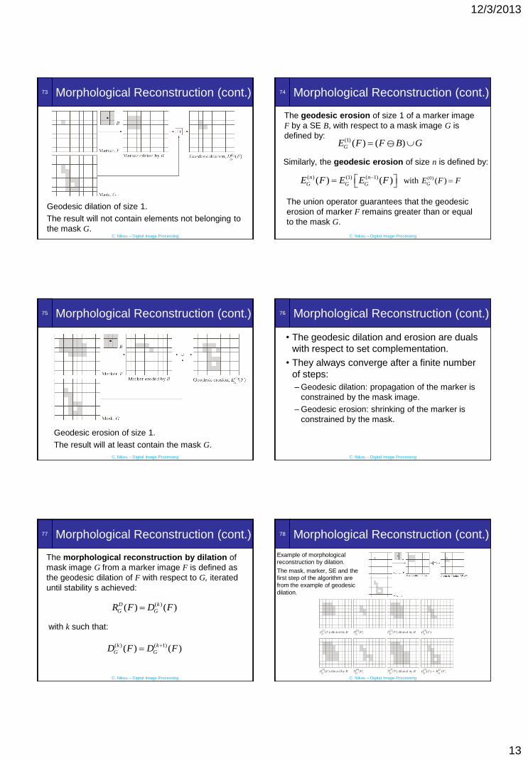
Morphological Reconstruction (cont.)
Geodesic dilation of size 1.
The result will not contain elements not belonging to
the mask G.
74
C. Nikou – Digital Image Processing
Morphological Reconstruction (cont.)
The geodesic erosion of size 1 of a marker image
F by a SE B, with respect to a mask image G is
defined by:(1) ( ) ( )GE F F B G
Similarly, the geodesic erosion of size n is defined by:
( ) (1) ( 1)( ) ( )n n
G G GE F E E F
The union operator guarantees that the geodesic
erosion of marker F remains greater than or equal
to the mask G.
(0)with ( )GE F F
75
C. Nikou – Digital Image Processing
Morphological Reconstruction (cont.)
Geodesic erosion of size 1.
The result will at least contain the mask G.
76
C. Nikou – Digital Image Processing
Morphological Reconstruction (cont.)
• The geodesic dilation and erosion are duals
with respect to set complementation.
• They always converge after a finite number
of steps:
– Geodesic dilation: propagation of the marker is
constrained by the mask image.
– Geodesic erosion: shrinking of the marker is
constrained by the mask.
77
C. Nikou – Digital Image Processing
Morphological Reconstruction (cont.)
The morphological reconstruction by dilation of
mask image G from a marker image F is defined as
the geodesic dilation of F with respect to G, iterated
until stability s achieved:
( ) ( 1)( ) ( )k k
G GD F D F
with k such that:
( )( ) ( )D k
G GR F D F
78
C. Nikou – Digital Image Processing
Morphological Reconstruction (cont.)
Example of morphological
reconstruction by dilation.
The mask, marker, SE and the
first step of the algorithm are
from the example of geodesic
dilation.

12/3/2013
14
79
C. Nikou – Digital Image Processing
Morphological Reconstruction (cont.)
The morphological reconstruction by erosion of
mask image G from a marker image F is defined as
the geodesic erosion of F with respect to G, iterated
until stability is achieved:
( ) ( 1)( ) ( )k k
G GE F E F
with k such that:
( )( ) ( )E k
G GR F E F
The example is left as an exercise!
80
C. Nikou – Digital Image Processing
Applications
Opening by Reconstruction
In morphological opening, erosion removes small
objects and dilation attempts to restore the shape of
the objects that remain without the small objects.
This is not accurate as it depends on the similarity
between the shapes to be removed and the SE.
Opening by reconstruction restores exactly the
shapes of the objects that remain after erosion.
81
C. Nikou – Digital Image Processing
Applications
Opening by Reconstruction (cont.)
The opening by reconstruction of size n of an image
F is defined as the reconstruction by dilation of F
from the erosion of size n of F:
( ) ( ) ( )n D
R FO F R F nB
The image F is used as the mask and the n
erosions of F by B are used as the initial marker
image.
82
C. Nikou – Digital Image Processing
Applications
Opening by Reconstruction (cont.)We are interested in extracting characters with long vertical
strokes (~50 pixels high).
Original image One erosion by a 51x1 SE
Opening Opening by reconstruction
83
C. Nikou – Digital Image Processing
Applications
Region filling
No starting point is needed to be provided.
The original image I(x,y) is used as a mask.
The marker image is
1 ( , ) if ( , ) is on the border of ( , )
0 otherwise
I x y x y IF x y
The binary image with all regions (holes) filled is
given by:( )c
cD
IH R F
Only dark pixels of I(x,y) touching the border
have a value of 1 in F(x,y).
84
C. Nikou – Digital Image Processing
Applications
Region filling (cont.)
We wish to fill the hole of the image I.
The complement builds a wall around the hole.
The marker image F is one at the border except
from border pixels of the original image.

12/3/2013
15
85
C. Nikou – Digital Image Processing
Applications
Region filling (cont.)
The dilation of the marker F starts from the
border and grows inward.
The complement is used as an AND mask: it
protects all foreground pixels (including the wall)
from changing during the iterations.
The last operation provides only the hole points.
86
C. Nikou – Digital Image Processing
Applications
Region filling (cont.)Original image Complement of original image
Marker image (1s almost everywhere
on the border apart of some points
on the right border)
Result of hole filling
87
C. Nikou – Digital Image Processing
Applications
Border Clearing
The extraction of objects from an image is a
fundamental task in automated image analysis.
An algorithm for removing objects that touch
(are connected) to the image border is useful
because
• only complete objects remain for further
processing.
• it is a signal that partial objects remain in the
field of view.
88
C. Nikou – Digital Image Processing
Applications
Border Clearing (cont.)
The original image is used as a mask.
The marker image is
( , ) if ( , ) is on the border of ( , )
0 otherwise
I x y x y IF x y
The border clearing algorithm first computes the
morphological reconstruction
which simply extracts the objects touching the
border and then obtains the new image with no
objects touching the borders
( ),D
IR F
( ).D
II R F
89
C. Nikou – Digital Image Processing
Applications
Border Clearing (cont.)
Original image I
Reconstruction by dilation of
the 1s touching the border
Reconstructed image ( )D
II R F
90
C. Nikou – Digital Image Processing
Gray-Scale Morphology
• The image f (x,y) and the SE
b(x,y) take real or integer
values.
• SE may be flat or nonflat.
• Due to a number of difficulties
(result interpretation, erosion is
not bounded by the image,
etc.) symmetrical flat SE with
origin at the center are
employed.
• Set reflection: ˆ( , ) ( , )b x y b x y

12/3/2013
16
91
C. Nikou – Digital Image Processing
Gray-Scale Erosion
The erosion of image f by a SE b at any
location (x,y) is defined as the minimum value
of the image in the region coincident with b
when the origin of b is at (x,y):
( , )
( , ) min{ ( , )}s t b
f b x y f x s y t
In practice, we place the center of the SE at
every pixel and select the minimum value of
the image under the window of the SE.
92
C. Nikou – Digital Image Processing
Gray-Scale Dilation
The dilation of image f by a SE b at any
location (x,y) is defined as the maximum value
of the image in the window outlined by b:
( , )
( , ) max{ ( , )}s t b
f b x y f x s y t
The SE is reflected as in the binary case.
93
C. Nikou – Digital Image Processing
Gray-Scale Erosion and Dilation
Original image Erosion by a flat disk SE of
radius 2:
Darker background,
small bright dots reduced,
dark features grew.
Dilation by a flat disk SE of
radius 2:
Lighter background,
small dark dots reduced,
light features grew.
94
C. Nikou – Digital Image Processing
Gray-Scale Morphology (nonflat SE)
The erosion of image f by a nonflat SE bN is
defined as:
( , )
( , ) min { ( , ) ( , )}N
N Ns t b
f b x y f x s y t b s t
The dilation of image f by a nonflat SE bN is
defined as:
( , )
( , ) max { ( , ) ( , )}N
N Ns t b
f b x y f x s y t b s t
When the SE is flat the equations reduce to
the previous formulas up to a constant.
95
C. Nikou – Digital Image Processing
Duality
As in the binary case, erosion and dilation are
dual operations with respect to function
complementation and reflection:
Similarly,
In what follows, we omit the coordinates for
simplicity.
ˆ( ) ( , ) ( )( , )c cf b x y f b x y
ˆ( ) ( , ) ( )( , )c cf b x y f b x y
96
C. Nikou – Digital Image Processing
Gray-Scale Opening and Closing
The opening of image f by SE b is:
( )f b f b b
They are also duals with respect to function
complementation and reflection:
The closing of image f by SE b is:
( )f b f b b
ˆ( )c cf b f b ˆ( )c cf b f b
12/3/2013
17
97
C. Nikou – Digital Image Processing
Gray-Scale Opening and Closing
(cont.)
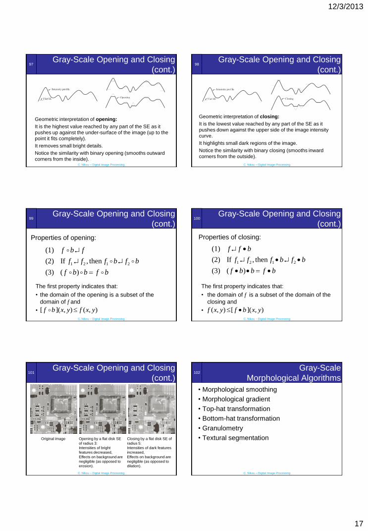
Geometric interpretation of opening:
It is the highest value reached by any part of the SE as it
pushes up against the under-surface of the image (up to the
point it fits completely).
It removes small bright details.
Notice the similarity with binary opening (smooths outward
corners from the inside).
98
C. Nikou – Digital Image Processing
Gray-Scale Opening and Closing
(cont.)
Geometric interpretation of closing:
It is the lowest value reached by any part of the SE as it
pushes down against the upper side of the image intensity
curve.
It highlights small dark regions of the image.
Notice the similarity with binary closing (smooths inward
corners from the outside).
99
C. Nikou – Digital Image Processing
Gray-Scale Opening and Closing
(cont.)
Properties of opening:
1 2 1 2
(1)
(2) If , then
(3) ( )
f b f
f f f b f b
f b b f b
The first property indicates that:
• the domain of the opening is a subset of the
domain of f and
• [ ]( , ) ( , )f b x y f x y
100
C. Nikou – Digital Image Processing
Gray-Scale Opening and Closing
(cont.)
Properties of closing:
1 2 1 2
(1)
(2) If , then
(3) ( )
f f b
f f f b f b
f b b f b
The first property indicates that:
• the domain of f is a subset of the domain of the
closing and
• ( , ) [ ]( , )f x y f b x y
101
C. Nikou – Digital Image Processing
Gray-Scale Opening and Closing
(cont.)
Original image Opening by a flat disk SE
of radius 3:
Intensities of bright
features decreased,
Effects on background are
negligible (as opposed to
erosion).
Closing by a flat disk SE of
radius 5:
Intensities of dark features
increased,
Effects on background are
negligible (as opposed to
dilation).
102
C. Nikou – Digital Image Processing
Gray-Scale
Morphological Algorithms
• Morphological smoothing
• Morphological gradient
• Top-hat transformation
• Bottom-hat transformation
• Granulometry
• Textural segmentation
12/3/2013
18
103
C. Nikou – Digital Image Processing
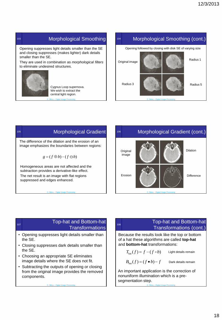
Morphological Smoothing
Opening suppresses light details smaller than the SE
and closing suppresses (makes lighter) dark details
smaller than the SE.
They are used in combination as morphological filters
to eliminate undesired structures.
Cygnus Loop supernova.
We wish to extract the
central light region.
104
C. Nikou – Digital Image Processing
Morphological Smoothing (cont.)
Opening followed by closing with disk SE of varying size
Radius 1
Radius 5Radius 3
Original image
105
C. Nikou – Digital Image Processing
Morphological Gradient
The difference of the dilation and the erosion of an
image emphasizes the boundaries between regions:
Homogeneous areas are not affected and the
subtraction provides a derivative-like effect.
The net result is an image with flat regions
suppressed and edges enhanced.
( ) ( )g f b f b
106
C. Nikou – Digital Image Processing
Morphological Gradient (cont.)
Original
image
Dilation
Erosion Difference
107
C. Nikou – Digital Image Processing
Top-hat and Bottom-hat
Transformations
• Opening suppresses light details smaller than
the SE.
• Closing suppresses dark details smaller than
the SE.
• Choosing an appropriate SE eliminates
image details where the SE does not fit.
• Subtracting the outputs of opening or closing
from the original image provides the removed
components.
108
C. Nikou – Digital Image Processing
Top-hat and Bottom-hat
Transformations (cont.)
Because the results look like the top or bottom
of a hat these algorithms are called top-hat
and bottom-hat transformations:
hat ( ) ( )T f f f b
hat ( ) ( )B f f b f
Light details remain
Dark details remain
An important application is the correction of
nonuniform illumination which is a pre-
segmentation step.

12/3/2013
19
109
C. Nikou – Digital Image Processing
Top-hat and Bottom-hat
Transformations (cont.)
Original image Thresholded image
(Otsu’s method)
Opened image
(disk SE r=40)
Does not fit to grains
and eliminates them
Top-hat reduced
nonuniformity
Thresholded top-hat
110
C. Nikou – Digital Image Processing
Granulometry
• Determination of the size distribution of particles in
an image. Particles are seldom separated.
• The method described here measures their
distribution indirectly.
• It applies openings with SE of increasing size.
• Each opening suppresses bright features where the
SE does not fit.
• For each opening the sum of pixel values is
computed and a histogram of the size of the SE vs
the remaining pixel intensities is drawn.
111
C. Nikou – Digital Image Processing
Granulometry (cont.)
Image of
wooden plugs
Smoothed
image
Opening by SE
of radius 20.
Small dowels
disappeared.
Opening by SE
of radius 10
Opening by SE
of radius 25
Opening by SE
of radius 30
Large dowels
disappeared.
112
C. Nikou – Digital Image Processing
Granulometry (cont.)
• Histogram of the differences of the total image
intensities between successive openings as a
function of the radius of the SE.
• There are two peaks indicating two dominant
particle sizes (of radii 19 and 27 ).
113
C. Nikou – Digital Image Processing
Textural segmentation
The objective is to find a
boundary between the
large and the small blobs
(texture segmentation).
The objects of interest
are darker than the
background.
A closing with a SE
larger than the blobs
would eliminate them.
114
C. Nikou – Digital Image Processing
Textural segmentation (cont.)
• Closing with a SE of radius 30.
• The small blobs disappeared as they have a
radius of approximately 25 pixels.

12/3/2013
20
115
C. Nikou – Digital Image Processing
Textural segmentation (cont.)
The background is lighter than the large blobs.
If we open the image with a SE larger than the
distance between the large blobs then the
blobs would disappear and the background
would be dominant.
116
C. Nikou – Digital Image Processing
Textural segmentation (cont.)
Opening with a SE of radius 60.
The lighter background was suppressed to the
level of the blobs.
117
C. Nikou – Digital Image Processing
Textural segmentation (cont.)
A morphological gradient with a 3x3 SE gives
the boundary between the two regions which is
superimposed on the initial image.
118
C. Nikou – Digital Image Processing
Textural segmentation (cont.)
Original imageClosing with a SE
of radius 30 (small
blobs are removed)
Opening with a SE
of radius 60 (large
blobs flooded the
background)
Morphological
gradient
superimposed onto
the original image
119
C. Nikou – Digital Image Processing
Gray-Scale Morphological
Reconstruction
The geodesic dilation of size 1 of a marker image f
by a SE b, with respect to a mask image g is defined
by:(1)( ) ( )gD f f b g
where
This equation indicates that the geodesic dilation of
size 1 is obtained by first computing the dilation of f
by b and then selecting the minimum between the
result and g at every point (x,y).
is the point-wise minimum operator.
120
C. Nikou – Digital Image Processing
Gray-Scale Morphological
Reconstruction (cont.)
The geodesic dilation of size n of a marker image f
by a SE b, with respect to a mask image g is defined
by:
( ) (1) ( 1)( ) ( )n n
g g gD f D D f
(0)with ( )gD f f

12/3/2013
21
121
C. Nikou – Digital Image Processing
Gray-Scale Morphological
Reconstruction (cont.)
The geodesic erosion of size 1 of a marker image
f by a SE b, with respect to a mask image g is
defined by:(1)( ) ( )gE f f b g
where
This equation indicates that the geodesic erosion of
size 1 is obtained by first computing the erosion of f
by b and then selecting the maximum between the
result and g at every point (x,y).
is the point-wise maximum operator.
122
C. Nikou – Digital Image Processing
Gray-Scale Morphological
Reconstruction (cont.)
The geodesic erosion of size n of a marker image f
by a SE b, with respect to a mask image g is defined
by:
( ) (1) ( 1)( ) ( )n n
g g gE f E E f
(0)with ( )gE f f
123
C. Nikou – Digital Image Processing
Gray-Scale Morphological
Reconstruction (cont.)
The morphological reconstruction by dilation of
gray scale image g from a marker image f is defined
as the geodesic dilation of f with respect to g,
iterated until stability is achieved:
( ) ( 1)( ) ( )k k
g gD F D F
with k such that:
( )( ) ( )D k
g gR F D F
124
C. Nikou – Digital Image Processing
Gray-Scale Morphological
Reconstruction (cont.)
The morphological reconstruction by erosion of
gray scale image g from a marker image f is defined
as the geodesic erosion of f with respect to g,
iterated until stability is achieved:
( ) ( 1)( ) ( )k k
g gE F E F
with k such that:
( )( ) ( )D k
g gR F E F
125
C. Nikou – Digital Image Processing
Gray-Scale Morphological
Reconstruction (cont.)
The opening by reconstruction of size n of an
image f is defined as the reconstruction by dilation
of f from the erosion of size n of f:
( ) ( ) ( )n D
R fO f R f nB
The image f is used as the mask and the n erosions
of f by b are used as the initial marker image.
Recall that the objective is to preserve the shape of
the image components that remain after erosion.
126
C. Nikou – Digital Image Processing
Gray-Scale Morphological
Reconstruction (cont.)
• The image has a size of
1134x1360.
• The target is to leave only
the text on a flat
background of constant
intensity
• In other words, we want to
remove the relief effect of
the keys.
12/3/2013
22
127
C. Nikou – Digital Image Processing
Gray-Scale Morphological
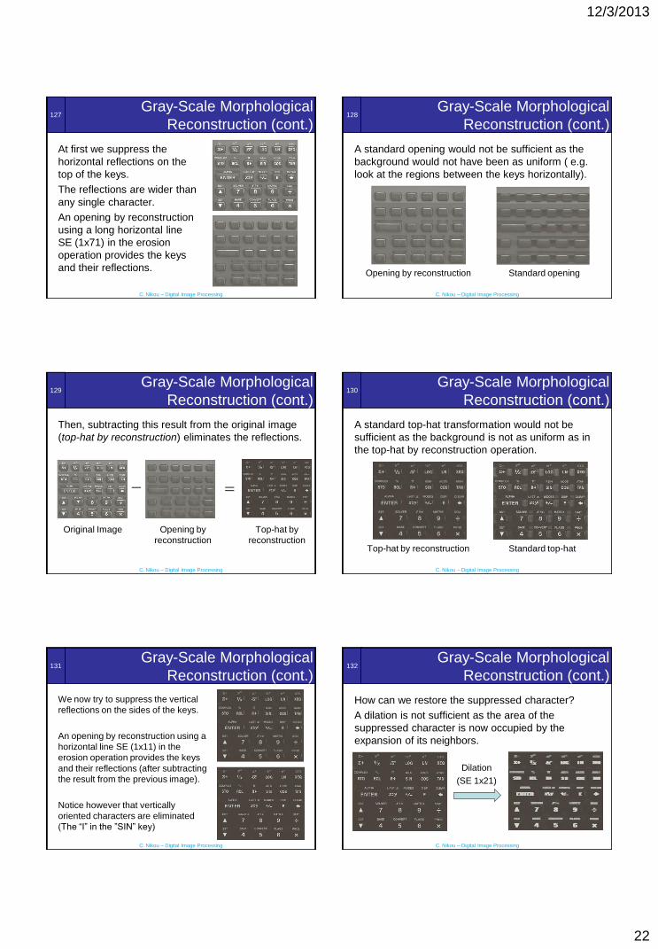
Reconstruction (cont.)
At first we suppress the
horizontal reflections on the
top of the keys.
The reflections are wider than
any single character.
An opening by reconstruction
using a long horizontal line
SE (1x71) in the erosion
operation provides the keys
and their reflections.
128
C. Nikou – Digital Image Processing
Gray-Scale Morphological
Reconstruction (cont.)
A standard opening would not be sufficient as the
background would not have been as uniform ( e.g.
look at the regions between the keys horizontally).
Opening by reconstruction Standard opening
129
C. Nikou – Digital Image Processing
Gray-Scale Morphological
Reconstruction (cont.)
Then, subtracting this result from the original image
(top-hat by reconstruction) eliminates the reflections.
Opening by
reconstruction
Original Image Top-hat by
reconstruction
130
C. Nikou – Digital Image Processing
Gray-Scale Morphological
Reconstruction (cont.)
A standard top-hat transformation would not be
sufficient as the background is not as uniform as in
the top-hat by reconstruction operation.
Top-hat by reconstruction Standard top-hat
131
C. Nikou – Digital Image Processing
Gray-Scale Morphological
Reconstruction (cont.)
We now try to suppress the vertical
reflections on the sides of the keys.
An opening by reconstruction using a
horizontal line SE (1x11) in the
erosion operation provides the keys
and their reflections (after subtracting
the result from the previous image).
Notice however that vertically
oriented characters are eliminated
(The “I” in the ”SIN” key)
132
C. Nikou – Digital Image Processing
Gray-Scale Morphological
Reconstruction (cont.)
How can we restore the suppressed character?
A dilation is not sufficient as the area of the
suppressed character is now occupied by the
expansion of its neighbors.
Dilation
(SE 1x21)

12/3/2013
23
133
C. Nikou – Digital Image Processing
Gray-Scale Morphological
Reconstruction (cont.)
We form an image by taking the point-wise minimum
between the top-hat by reconstruction image and the
dilated image:
Dilated imageTop-hat by
reconstruction
The result is close to
our objective but the
“I” is still missing
134
C. Nikou – Digital Image Processing
Gray-Scale Morphological
Reconstruction (cont.)
Using the last image
as a marker and the
dilated image as a
mask we perform a
gray-scale
reconstruction by
dilation and we obtain
the desired result.
Marker Mask
Result
Recommended