1
Direct Simulation of the Sedimentation ofElliptic Particles in Oldroyd-B Fluids
by P. Y. Huang1, H. H. Hu2 and D. D. Joseph1
1Department of Aerospace Engineering and Mechanics and the Minnesota Supercomputer Institute,University of Minnesota, Minneapolis, MN 55455-0153, USA
2Department of Mechanical Engineering and Applied Mechanics, University of Pennsylvania,Philadelphia, PA 19104-6315, USA
January 1997
Abstract. Cross stream migration and stable orientations of elliptic particles falling in an
Oldroyd-B fluid in a channel are studied. We show that the normal component of the
extra stress on a rigid body vanishes; lateral forces and torques are determined by the
pressure. Inertia turns the longside of the ellipse across the stream and elasticity turns it
along the stream; tilted off-center falling is unstable. There are two critical numbers;
elasticity and Mach numbers. When the elasticity number is smaller than critical the fluid
is essentially Newtonian with broadside-on falling at the centerline of the channel. For
larger elasticity numbers the settling turns the longside of the particle along the stream in
the channel center for all velocities below a critical one, identified with a critical Mach
number of order one. For larger Mach numbers the ellipse flips into broadside-on falling
again. The critical numbers are functions of the channel blockage ratio, the particle aspect
ratio and the retardation/relaxation time ratio of the fluid. Two ellipses falling nearby,
attract, line-up and straighten-out in a long chain of ellipses with longside vertical, all in a
row. Stable, off-center tilting is found for ellipses falling in shear thinning fluids and for
cylinders with flat ends in which particles tend align their longest diameter with gravity.
___________________________________________________________________
1. Introduction
Direct simulation uses the full power of computers to obtain exact solutions of initial-
boundary value problems for the motion of dispersed particles, here rigid solids, in a

2
liquid. Of course, such solutions can be no more exact than the numerical methods, but
they are faithful to the underlying dynamics in which rigid bodies move under Newton’s
laws impelled by hydrodynamic forces arising from the solutions of the fluid equations at
each nodal point in the fluid. The solutions of initial value problems for thousands of
particles in three dimensions is not a dream for the future, but is an immediate goal
towards which this paper takes one small step. Already Hu (1996) has reported
simulations of sedimenting and shear flows of 400 spherical particles (discs in 2D) and
simulations of thousands of these discs in Newtonian fluids and hundreds in viscoelastic
fluids will be reported soon (see Direct simulation of particles in flowing liquids: NSF
Grand Challenge Project: http://www.aem.umn.edu/Solid-Liquid_Flows/ for more
information and video animations.)
The solution of initial value problems is the goal of analysis of dynamical systems
leading to understanding of how systems dynamics depend on initial conditions, the
nature of transients and the characterizing features of sets of permanent solutions which
evolve after transients decay.
Direct two-dimensional simulations of the sedimentation of spherical particles (discs)
in a vertical channel filled with an Oldroyd-B fluid were done by Feng, Huang and
Joseph (1996) emphasizing wall-particle interactions. Using the same scheme, Huang,
Feng, Hu and Joseph (1996) studied the motion of spherical particles in Couette and
Poiseuille Flows. A video animation of direct simulation of groups of sedimenting
spherical discs by Hu and Joseph (1997) can be seen on our web page; there chains of
spheres (discs) line up with gravity and it is natural to ask what holds the chains together
and how are the chains stabilized (see figure 2)? The existence of aggregated chains of
spheres in viscoelastic fluids contrasts with the dispersed arrays of spheres which line up
across the stream in Newtonian fluids. What are the underlying mechanisms which lead
to such a large difference in the arrangement of spheres sedimenting in Newtonian and
viscoelastic fluids?

3
It is surprising at first sight that turning couples on long bodies determine the stable
configurations of suspensions of spherical bodies. A long body is an ellipsoid or a
cylinder; a broad body is a flat plate. When such bodies are dropped in Newtonian fluids,
they turn and put their long or broadside perpendicular to the stream. This is an effect of
inertia which is usually explained by turning couples at points of stagnation. Milne-
Thompson (1968, page 530) notes that
There are many well-known phenomena which are explained in principleby this remark. Thus a ship has to be kept on her course by the helmsman;an elongated airship requires similar attention. A sailing ship will not sailpermanently before the wind with the helm lashed, but tends to set itself atright angles to the wind. A body sinking in liquid tends to sink with itslongest dimension horizontal.
It is not possible to get long particles to turn broadside in a Stokes flow; bodies in an
infinite fluid with fore-aft symmetry do not experience torques. The settling orientation is
indeterminate in Stokes flow; however, no matter how small the Reynolds number may
be, the body will turn its broadside to the stream; inertia will eventually have its way.
When the same long bodies fall slowly in a viscoelastic liquid, they need not put their
broadside perpendicular to the steam; they can do the opposite, aligning the long side
parallel to the stream.
The flow-induced anisotropy of a sedimenting or fluidized suspension of spheres is
determined by the pair interactions between neighboring spheres. The principle
interactions can be described as drafting, kissing and tumbling in Newtonian liquids and
as drafting, kissing and chaining in viscoelastic liquids. The drafting and kissing
scenarios are surely different, despite appearances. Kissing spheres align with the stream;
they are then momentarily long bodies.
The long bodies momentarily formed by kissing spheres are unstable in Newtonian
liquids to the same turning couples that turn long bodies broadside-on. Therefore, they
tumble. This is a local mechanism which implies that globally, the only stable
configuration is the one in which the most probable orientation between any pair of

4
neighboring spheres is across the stream. The consequence of this microstructural
property is a flow-induced anisotropy, which leads ubiquitously to lines of spheres across
the stream; these are always in evidence in two-dimensional fluidized beds of finite size
spheres. Though they are less stable, planes of spheres in three-dimensional beds can also
be found by anyone who cares to look. The long bodies formed by kissing spheres in
viscoelastic fluids are stable to turning couples whenever long bodies aligned along the
stream are stable.
θθθθαααα
x
y
s
s
c
c
g
Figure 1. Slow flow around an elliptic particle. θ is the tilt angle of the major axis and the horizontal. α is
the angle of a typical surface node of the particle. There are two stagnation points s where the shear stress
vanishes and two other points c where the streamlines are most crowded. The shear stresses and normal
stresses are strongest at c. The nonlinear contribution of the normal stresses in slow flow at each point on
the ellipse is given by − Ψ1(0) Ý γ 2 where Ψ1 (0) > 0 is the coefficient of the first normal stress difference
and Ýγ is the shear rate. These normal stresses are compressive and give rise to “high pressure” at points
near where the flow is fast, opposing the high pressure at points s which turn the ellipse broadside-on
(θ=180o) (Joseph & Feng, 1996). If the normal stresses at points c dominate at all θ, the major axis of the
ellipse will align with gravity (θ=90o).
5
Joseph & Feng (1996) and Joseph (1996) did analysis of the forces that move
particles in slow plane flow of a second-order fluid; a model that applies to our
simulations when the Reynolds and Deborah numbers are small. Their analysis can be
used to set the stage for our simulations. They showed that the normal component of the
non-linear elastic part of the normal stress is always compressive and turns long bodies
into the stream (see figure 1). Joseph (1996) presented a heuristic argument that normal
stresses are amplified by shear thinning at points of high shear. Effects of this
amplification by shear thinning are demonstrated in the simulation of Huang, Feng, Hu
and Joseph (1996) and in section §12 here.
In all our arguments we suppose that the normal stresses due to viscoelasticity (near c
in figure 1) dominate inertial effects (near s in figure 1) which are strongest near
stagnation points. Later, we shall argue that these stresses come to dominate when the
elasticity number is larger than some critical value.
The cartoons shown in figure 2 show how the migrations and orientations of particles
are controlled in slow flows by compressive normal stresses −Ψ1 (0) Ý γ 2 which are large
where the shear rates are large (indicated by the length of arrows). In general these
compressive stresses cause particle to line up, straighten out and aggregate.

6
cc
F
(a) (b)
F
s
cc
scs
c s
(c)
F
(d)
F c
s
c
cc
c sF
F
Figure 2. The orientation and migrations of particles in slow flow of a fluid dominated by viscoelasticity
can be determined from Stokes flow around that body, with large normal stresses where the shear rates on
the body are large, near the places where the streamlines are crowded (see figure 1) (a) There are two
symmetric orientations with respect to gravity for a falling square (cube); the one with flat faces
perpendicular is unstable; the stable orientation is when the line between vertices is parallel to gravity; (b) a

7
rectangle or cylinder with flat ends (Joseph and Liu 1993) tends to line up with the longest line in the body
parallel to gravity. Falling bodies tilt when the longest line in the body is not an axis of symmetry; this is
called shape tilting; (c) Falling ellipses tend to straighten out, line up and chain; (d) Perturbed chains
straighten out.
In this paper we are going to focus our attention on the migration and stable terminal
orientation of long bodies settling in viscoelastic fluids. The fluid is assumed to be
Oldroyd-B, computing for two cases: Maxwell models in which the ratio of retardation
time/relaxation time is zero and when it is 1/8. The Oldroyd-B models have no second
normal stress and we shall prove that the normal component of the extra stress vanishes
on the boundary of a rigid solid. This means that the effects of inertia and viscoelasticity
are to be found only in the reaction pressure evaluated on the body.
Hu, Joseph and Crochet (1992), Feng, Hu and Joseph (1994) and Huang, Feng and
Joseph (1994) have shown that an ellipse sedimenting in a Newtonian fluid turns
broadside-on but at high Reynolds numbers vortex shedding will make it oscillate.
The orientation of long particles in viscoelastic fluids are broadside-on when inertia
dominates and along the stream when viscoelasticity dominates and shape and wall
effects are not important. Leal (1975) studied slender cylinders falling slowly in glycerin
and in a 0.5% aqueous solution of polyacrylamide (AP-30). He observed that the cylinder
rotated into a vertical orientation in the AP-30 solution regardless of the initial
orientation. Chiba, Song & Horikawa (1986) studied the motion of a slender body falling
in quiescent polymer solutions and in water. They demonstrated that a slender body
falling in Newtonian fluids rotates into a horizontal orientation, whereas in viscoelastic
fluids it rotates into a vertical orientation; for less concentrated solutions it tilts away
from vertical and moves sideways as it falls. Liu & Joseph (1993) reported that the
orientation of a long body settling in a viscoelastic fluid is determined by a competition
between inertia and viscoelasticity. They concluded that viscoelasticity dominates when
inertia is small and the particles settle with their broadside parallel to the direction of fall;

8
the same particles settle with their broadside perpendicular to the direction of fall when
the inertia is large.
An interpretation of these experiments, analysis and this simulation may be framed in
terms of a competition between inertia and normal stresses. The ellipse turns its long side
perpendicular to the fall when inertia dominates and parallel to the fall when normal
stresses dominate. Tilted orientations of long bodies, neither horizontal or vertical, which
are definitely observed in experiments and the numerical simulations reported here will
be interpreted as transient effects arising from walls, as an effect of shear thinning (see
section §12) or from shape tilting in which the normal stresses tend to line up bodies so
that the longest line in the body is turned parallel to the fall; a square body then settles
along a line between vertices whereas an ellipse lines its long axis parallel to the flow.
The scenario just described is best framed as a stability hypothesis for two steady
states; the ellipse falls with its long axis either vertical or horizontal at a terminal velocity
determined by a balance between buoyant weight and drag. A model for this stability
hypothesis can be found in Kirchoff’s theory of motion of solid ellipsoids through liquids
in potential flow in which the principal axes of the ellipsoid are directions of permanent
translation such that if the solid is set moving along one of them without rotation, it will
continue to move so. In our two-dimensional problem there are two such directions, one
perpendicular and the other parallel to the long side of the ellipse. The solution with long
side parallel is unstable to inertia, to couples associated with high pressure at stagnation
points as shown in figure 1. We have already noted that viscous effects change many
features of the motion of bodies profoundly, but the turning couples from high pressures
near stagnation points at the front of a falling ellipse dominate and again turn it across the
stream.
Viscoelastic fluids are different from viscous fluids because normal stresses arise both
from inertia proportional to the square of the velocity and from elasticity proportional to
the square of the shear-rate Ý γ 2 . The normal stress from inertia is strongest where the flow

9
is slow and the normal stress from viscoelasticity is strongest where the flow is fast
(points c in figure 1). The competition between these two normal stresses, one due to
inertia and the other to viscoelasticity could be resolved in angle of tilt in which turning
from the two are balanced or they could be unbalanced leading to broadside-on settling
when inertia dominates and broadside-along settling when viscoelasticity dominates.
In the case of inviscid and viscous liquids, the steady solution with major axis aligned
with gravity or tilted is always unstable; hence only steady solutions with major axis
across gravity can be observed. There are no critical stability parameters. But in
viscoelastic solutions, long bodies line up with or across the stream, depending on
conditions which ought to be described in mathematical terms by critical parameters.
To identify critical parameters, consider the case of an ellipse settling under gravity in
an upper convected Maxwell fluid. The fluid dynamics of such a flow is described by the
aspect ratio a/b of the ellipse and two fluid parameters:
Re = ρ fUa η (Reynolds number)
De = Uλ 1 a (Deborah number)
where ρf is the density of the fluid, U is the terminal velocity of the ellipse which is
determined by a balance buoyant weight and density, a is the major radius of the ellipse,
λ1 is the relaxation time and η is the viscosity of the fluid. Obviously, these two
parameters are independent and any other composition of these two would be just as
good; the product
ReDe = U η λ 1ρ f ====def
M (Mach number)
and the ratio
De / Re = λ1η ρ f a2 =def
E (Elasticity number)
are even better. The Mach number is the ratio of the terminal velocity to the shear wave
speed c = η λ 1ρ f . The elasticity number depends on material parameters and particle
size but is independent of flow. It is the ratio of the elastic and inertia forces in the fluid.

10
In previous works (Liu and Joseph 1993, Joseph and Liu 1993, Joseph 1996) which
addressed the change in orientation of falling cylinders of the same size and shape but
different weights falling in each of many viscoelastic fluids in terms of the Mach and
Reynolds numbers. The light cylinders lined up with the flow, but the heavy cylinders
turned broadside-on. This change from vertical to horizontal falling occurs when the
stagnation pressures at the front of the falling body are dominated by inertia. For this to
happen, the body must fall faster than diffusion U > η ρ f a (hence Re>1) and faster than
shear waves (hence M>1).
The previous results allowed for a range of Mach and Reynolds numbers of order one
in which the competition of inertia and viscoelasticity could be resolved by a tilt angle in
which the terminal orientation of the long side is tilted, neither vertical or horizontal (see
Feng, Joseph, Glowinski & Pan, 1995). In studying the results of the simulation reported
here, we have come to believe that the observed tilt is most probably due to wall effects
and is either transient or is stabilized by shear thinning. This observation, and a review of
the experiments, led Joseph to reformulate the explanations of the observations in terms
of the stability of the vertical or horizontal orientation with tilt disallowed. Here we shall
promote an explanation of stability framed in terms of the elasticity and Mach numbers.
These parameters were advocated as a canonical basis for problems of flow past bodies
which change their type, in Chapter 6 of Joseph’s book (Joseph, 1990).
In the reformulated explanation there are two critical numbers; a critical elasticity and
a critical Mach number. Both numbers mark borders in which the balance between inertia
and viscoelasticity changes. For elasticity numbers smaller than critical the ellipse falling
in an unbounded fluid will turn its long side across the fall, broadside-on, for all speeds,
large or small. The critical elasticity number marks the border between effectively
Newtonian and effectively viscoelastic behavior. The ellipse turns broadside-on as in a
Newtonian fluid when viscoelastic effects measured by the Deborah number are no larger
than a certain measure of inertia involving the Reynolds number; this is expressed
11
precisely by requiring that E = De Re be smaller than a critical value which we find by
simulation. When this ratio is larger than critical, the orientation of the ellipse is reversed,
the horizontal orientation is unstable, and the vertical orientation of the long side is
stable; it is a dramatic change in stability. Experiments corresponding to changes in the
elasticity number were carried out by Chiba, Song & Horikawa (1986) who studied the
settling of one cylinder in an aqueous solution as a function of concentration, with
broadside-on turning for dilute solutions and along the stream turning for concentrated
solutions. At intermediate concentration tilted cylinders with side drift were observed.
The critical Mach number represents a different physics, corresponding to the
experiments of Liu and Joseph (1993) and Joseph and Liu (1993) in which the fluid, size
and shape of particles is fixed and the weight of the particle is varied. Now we focus our
attention on effectively viscoelastic fluids in which the elasticity number is greater than
critical. In our simulation, described in section §7, we may take the critical E as three and
consider along the stream falling with De / Re = 4 . This means the Deborah number will
be four times the Reynolds number no matter what the value of the velocity. The terminal
velocity is increased by changing the weight of the particles and when the particle is
heavy enough so the M pass some number near one, the particle flips falling broadside
on. In this case the critical M near one is a border marking the place at which the fall
velocity is larger than the propagation speeds of signals, and is again dominated by
pressures in an effectively potential flow at the front of the body. If this border is at
M = ReDe = 1 and De = 4Re , the transition to broadside on turning would occur when
Re=0.5.
2. Governing equations
An incompressible fluid is bounded in a two-dimensional region Ωt with boundary Γt
formed from fixed walls and N rigid particles which can move freely in the fluid. The
12
velocity field u(x,t) and pressure field p(x,t) in the fluid is governed by the equations of
motion:∇ ⋅ u = 0
ρf( ∂u
∂ t+ u ⋅ ∇ u) = −∇ p + ∇ ⋅ T = ∇ ⋅ σσσσ
(1)
where ρf is the density of the fluid, σσσσ = −p1 + T and T is the extra stress tensor. For an
Oldroyd-B fluid, the extra stress tensor is given by the constitutive equation:
T + λ1 T∇
= η (A + λ2 A∇
) (2)
where A = ( ∇ u + ∇ uT ) is the strain-rate tensor; λ1 and λ2 are constant relaxation and
retardation times; η is the viscosity of the fluid. The fluid reduces to an upper convected
Maxwell model when λ2=0. The triangle denotes the upper-convected time-derivative:
T∇
=∂T∂t
+ u ⋅ ∇ T − L ⋅ T − T ⋅ LT (3)
where L ij = ∂ui / ∂xj is the velocity gradient tensor. Shear-thinning can be easily
incorporated to the Oldroyd-B model by using the Carreau-Bird viscosity law:
η − η∞
η0 − η∞
= 1+ λ 3Ý γ ( )2[ ]
n −12 (4)
where Ýγ is the strain-rate defined in terms of the second invariant of A and 0<n≤1. The
motion of solid particles satisfies the Newton’s law:
M dU p
dt= F p + Gp
dX p
dt= Up
, p=1,2,...N (5)
where M is the generalized mass matrix of the particle, X and U are the generalized
position and velocity vectors of the particle, F is the generalized force vector imposed on
the particle by the fluid and G is the body force exerted by external fields such as gravity.
The mass matrix M and the vectors can be written explicitly as:
13
M =m 0 00 m 00 0 I
, X =XYθ
, U =
UVΩ
,
and F =Fx
Fy
Fm
, G = (ρs − ρ f )gπab
100
,
where m = ρsπab and I =14
(a2 + b2 )ρsπab are the mass per unit length and the polar
moment per unit length of inertia of the elliptic particle. The force and the torque
imposed on a solid particle by the fluid is given by:
Fx, Fy[ ]= (−p1 + T) ⋅ ˆ n dΓΓ p
Fm = (x − X p ) × (− p1 + T) ⋅ ˆ n dΓΓ p
(6)
where Γp is the surface of the particle, ˆ n is the outward unit normal vector on the surface
of particles (figure 3).
A dimensionless set of governing equations can be obtained from the equations just
given by introducing scales:
a (semi major axis) for length,
U velocity,
a / U time,
ηU a stress and pressure.
When written in terms of dimensionless variables, using the same symbols for both, we
have
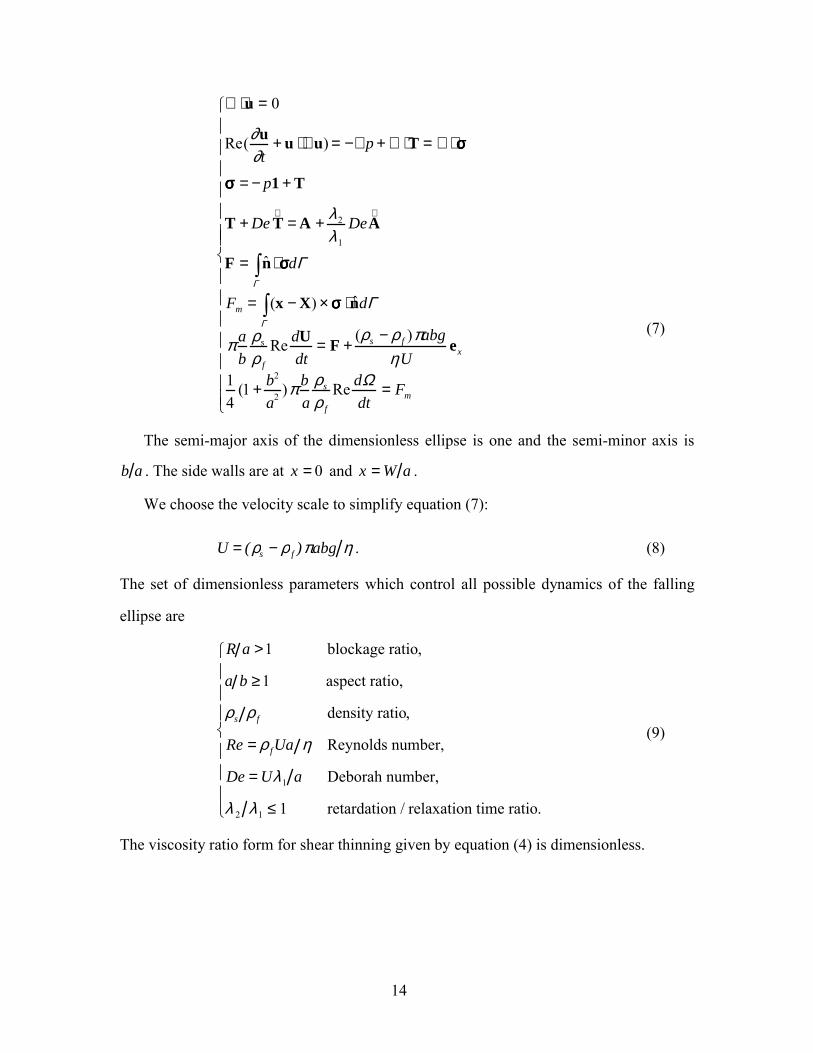
14
∇ ⋅ u = 0
Re(∂u∂t
+ u ⋅ ∇ u) = −∇ p + ∇ ⋅ T = ∇ ⋅ σσσσ
σσσσ = −p1 + T
T + De T∇
= A + λ 2
λ 1
DeA∇
F = ˆ n ⋅ σσσσdΓΓ
Fm = (x − X) × σσσσ ⋅ ˆ n dΓΓ
πab
ρs
ρ f
Re dUdt
= F +(ρs − ρ f )πabg
ηUex
14
(1 + b2
a2 )πba
ρs
ρ f
Re dΩdt
= Fm
(7)
The semi-major axis of the dimensionless ellipse is one and the semi-minor axis is
b a . The side walls are at x = 0 and x = W a .
We choose the velocity scale to simplify equation (7):
U = (ρs − ρ f )πabg η . (8)
The set of dimensionless parameters which control all possible dynamics of the falling
ellipse are
R a >1 blockage ratio,
a b ≥1 aspect ratio,
ρs ρ f density ratio,
Re = ρ fUa η Reynolds number,
De = Uλ 1 a Deborah number,
λ 2 λ 1 ≤ 1 retardation / relaxation time ratio.
(9)
The viscosity ratio form for shear thinning given by equation (4) is dimensionless.
15
In our simulation (ρs
ρ f
−1) ≥ 0 is small and ρs
ρ f
on the left side of equation (7) could
be put to one without loss of accuracy. However the difference (ρs −ρ f ) is the main
control parameter used to control velocity.
3. Normal stress at the boundary of a rigid body
Caswell (1967) claims to have proved that all flows become viscometric at a solid
surface at rest. Here we consider moving bodies. We find that the turning couples on long
bodies and the cross stream migrations of solid particles are controlled mainly by the
pressure. This is no accident; it follows from the fact that the normal component of the
extra stress on the boundary of a rigid body vanishes in all incompressible Oldroyd-B
fluids. To simplify the demonstration, consider the motion of solid body in two
dimensions and pick a generic point on the boundary, calling the direction tangent to the
boundary at this point x and the outward normal direction y. Tangential derivatives of
velocity vanish along the boundary of a rigid solid even as it moves, and the continuity
equation then requires that the normal derivative of normal velocity also vanish. Then, at
this boundary point
L =0 Ý γ 0 0
, A =
0 Ý γ Ý γ 0
, T =τ x τ xy
τ xy τ y
(10)
The stress is given by
σσσσ = −p1 + T (11)
where T is the extra stress. For Newtonian fluids T = ηA and τ x = τy = 0 ; hence
σyy = σ xx = −p (12)
at every boundary point. For Oldroyd-B fluids we have
τ y + λ(∂τ y
∂t+U
∂τ y
∂x+ V
∂τ y
∂y) = 0 (13)
or

16
τ n + λ (∂τ n
∂t+ U ⋅ ∇ τ n ) = 0 (14)
where τ n = τy and U=(U,V) is the velocity on the surface of the solid due to rigid body
motion. We conclude that τ n = 0 and
σnn = −p (15)
at every point of the boundary of the solid. All the results just given will still hold in
three-dimensions.
In general, pressure can not be given a priori, but it can be given for potential flows
(Joseph & Liao, 1994) through Bernoulli’s equation and in the case of second order fluids
in two dimensions (Tanner, 1966) and in three dimensions when the normal stress
coefficients satisfy the condition Ψ1 = −2Ψ2 (Giesekus, 1963). Joseph (1996) and Joseph
& Feng (1996) used this result for second order fluids to obtain an explicit a priori
expression for σnn in which the viscoelastic contribution is always compressive and
given by −Ψ1
2Ý γ 2 where Ýγ is the shear rate at the boundary. The normal component of
the extra stress τ n = 0 and σnn = −p at all points of the boundary if and only if the
coefficient Ψ2 of the second normal stress difference vanishes, as it does in Oldroyd-B
fluids.
4. Numerical method
Direct simulation of the motion of particles has been carried out by using a two-
dimensional generalized Galerkin finite element method which incorporates both the
fluid and particle equations of motion into a single coupled variational equation. An
arbitrary Lagrangian-Eulerian (ALE) moving mesh technique was used to compute the
motion of the particles. The modified code with EVSS (Elastic-Viscous-Split-Stress)
scheme for solving transient Navier-Stokes equations together with a moving finite
element mesh can be used to simulate the unsteady motion of the viscoelastic fluid and
the solid particles directly. In our implementation, the nodes on the particle surface are
assumed to move with the particle. The nodes in the interior of the fluid are computed

17
using Laplace’s equation, to guarantee a smoothly varying distribution. At each time step,
the grid is updated according to the motion of the particles and checked for element
degeneration. If unacceptable element distortion is detected, a new finite element grid is
generated and the flow fields are projected from the old grid to the new grid. The fluid is
at rest initially and the particles are positioned in the fluid with zero velocity. The
particles are then released and the motion of the combined system of viscoelastic fluid
and solid particles is computed. In this scheme, the positions of the particles and grid
nodes are updated explicitly, while the velocities of the fluid and the solid particles are
determined implicitly. In our computations, the elliptic particles at rest initially, are
heavier than the fluid (ρ f = 1.0g cm3) and settle under gravity (figure 3). The inflow
boundary of the computational domain is placed 30a ahead of the elliptic particle and the
outflow boundary is 40a behind of the particle. We use an unstructured mesh triangular
elements. A typical mesh used for R/a=10 has 2286 elements and 4688 nodes.
xW=2R
2a
y
Y
θ
U
X
g
Figure 3. Sedimentation of an elliptic particle in a 2-D channel. W is the width of the channel. (X, Y) is the
position of the center of the elliptic particle. θ is the orientation of its major axis.
5. Critical Reynolds number for horizontal turning of an ellipse falling in a
Newtonian fluid between close walls

18
Here we shall show that an ellipse which settles in a Newtonian fluid will turn
vertical when the Reynolds number is below a critical value, as shown in figure 4.
Formerly we thought that inertia would always turns a long particle settling in a
Newtonian fluid horizontal at any Reynolds number greater than zero. The only literature
we know on the subject is the numerical study of Huang, Feng & Joseph (1994) where
the blockage ratio was small (R/a=4) but the Reynolds number is so large (Re≈56) that
only horizontal turning could occur.

19
θ
0.35
0.4
0.45
0.5
0.55
0.6
0.65
Y/W
0 10 20 30 40 50
X/W60 70
Re=0.82, De=0.00
Re=0.31, De=0.00
Figure 4. Orientation θ and trajectory Y/W of an ellipse (a/b=1.5) settling in a Newtonian fluid (De=0)
between close walls (R/a=5). At Re=0.31, the ellipse turns vertical and executes a damped oscillation as it
drifts to the channel center; at Re=0.82, the ellipse turns horizontal as it migrates to the channel center.

20
Plastic particle
with round ends
(a)
2a2b
(b)
Figure 5. (a) A plastic long particle with round ends used in the experiment; (b) the long particle turns its
longside parallel to the stream under the effects of lubrication in a Newtonian fluid when the channel is
very narrow and the settling is very slow.
Since the numerical result of figure 4 is new and unexpected we did an experiment to
see if vertical turning for slow settling between close walls could occur. A cylindrical
particle with round ends (see figure 5(a)) was dropped in a vertical channel. The
Newtonian fluid used in the experiment was pure glycerin, with density ρf=1.26 g cm3
and viscosity µf=13.0 g cm ⋅ s . The solid particle is made of plastic of density ρs=1.36
g cm3 . The length of the particle is 2a=1.32 cm and the diameter is 2b=0.635 cm. The
sedimentation channel has a square section with its width W=2R=2.2 cm. The terminal
mean sedimenting velocity of the particle is about V=0.2 cm s . The controlling
dimensionless parameters in the experiment are: the blockage ratio R/a=1.7, the aspect
21
ratio a/b=2.1 and the Reynolds number Re = ρ fVa µ f = 0.013. A cartoon of the settling
of the solid particle is shown in figure 5(b). The particle oscillates before it turns to its
equilibrium vertical orientation at the centerline of the channel, as in our numerical
computation. When a heavier particle with the same shape and size is dropped, it turns
horizontal.
The explanation of vertical turning of an ellipse in a narrow channel is probably
found in lubrication forces at low Reynolds number which would tend to produce high
pressures in the converging gap between the walls at the top and bottom of the tilted
ellipse. These pressures give rise to torques at both ends of the ellipse turning the ellipse
vertical. The lubrication pressure is linearly proportional to the velocity of the settlement.
At higher speeds, stagnation pressures which turn the ellipse horizontal come to
dominate.
6. Universal features of equilibrium orientation and positions of an elliptical particle
Many experiments cited in this paper and our simulations live in a range of
parameters leading to steady sedimentation so that unsteadiness is transient. After
transients decay the ellipse will enter into motion with a permanent character. By an
equilibrium we mean steady permanent motions, with a final terminal velocity,
orientation and no lateral migration. The equilibrium orientation of the ellipse is
perpendicular or parallel to the fall when the final position of the particle center is at the
center of the channel, and vice versa. This correlation holds for channels of blockage
ratio larger than R a =1 (that we tested), independent of a b , λ 2 λ1 , ρs ρ f , De or Re.
The turning couples on an ellipse are due to inertia and the viscoelastic normal
stresses. Since these couples have opposite signs, with magnitudes that vary with the tilt
angle, it is possible that tilted zero torque solutions exist off center, stabilized by wall
effects. Such solutions can be found but they all appear to be unstable to small
perturbations leading again to symmetric orientations at the channel center.
22
Assuming now that symmetric orientations at the channel center are the only stable
equilibria, it remains to determine the conditions under which these equilibria are vertical
or horizontal. We find critical elasticity, critical Mach and apparently critical blockage
numbers to distinguish between stable vertical and horizontal orientations. When the
elasticity number is smaller than critical, the ellipse turns broadside on; above this
number stable vertical orientations are found in all cases for which the viscoelastic Mach
number is less than a critical Mach number of order unity (see figures 6 and 7). The effect
of the blockage ratio is more complicated; we find that the critical elasticity number E is
a monotonically increasing function of the blockage ratio R/a with an asymptotic value of
E for large R/a and a finite intercept R/a for E=0 (see figure 8).
The critical Mach numbers are associated with the speed of falling particles in the
cases in which the elasticity number is greater than critical. In such cases, as we have
already mentioned, the ellipse turns vertical apparently at all Mach number less than a
critical value of order one; at Mach number greater than this, the ellipse ultimately turns
horizontal, just the opposite. Unfortunately, we can play only at the margins of this
condition because our simulations fail at high Deborah numbers; the results at this margin
are totally consistent with the experiments of Liu & Joseph (1993) and Joseph & Liu
(1993).

23
U
0.48
0.5
0.52
0.54
0.56
0.58
0.6
Y/W
0 10 20 30 40 50
X/W
(A)
R/a=5, Re=0.82, De=0.16, E=0.2, M=0.37
60
U
0.48
0.5
0.52
0.54
0.56
0.58
0
Y/W
10 20 30 40 50 60
X/W70 80
R/a=5, Re=1.00, De=0.50, E=0.5, M=0.71
(B)
Figure 6. The orientation θ and trajectory Y/W of an ellipse of ratio a/b=1.5 falling in a Maxwell fluid in a channel with blockage ratio R/a=5 at Reynolds
numbers: (A) E=0.2, Re=1.00, De=0.50, M=0.71. The ellipse migrates to the center and turns horizontal. (B) E=0.5, Re=0.82, De=0.16, M=0.37. The ellipse
migrates to the center and turns vertical.
24
U
0.45
0.5
0.55
0.6
0.65
0.7
0
Y/W
5 10 15 20 25 30
X/W35 40
R/a=30, Re=0.59, De=1.18, E=2.0, M=0.84
(A)
U
0.48
0.5
0.52
0.54
0.56
0.58
0.6
Y/W
0 5 10 15 20 25
X/W
R/a=30, Re=0.59, De=2.36, E=4.0, M=1.18
(B)
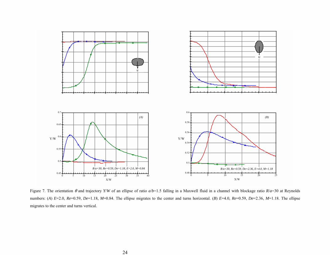
Figure 7. The orientation θ and trajectory Y/W of an ellipse of ratio a/b=1.5 falling in a Maxwell fluid in a channel with blockage ratio R/a=30 at Reynolds
numbers: (A) E=2.0, Re=0.59, De=1.18, M=0.84. The ellipse migrates to the center and turns horizontal. (B) E=4.0, Re=0.59, De=2.36, M=1.18. The ellipse
migrates to the center and turns vertical.

25
7. Critical values of elasticity number for Maxwell models (λλλλ 2 = 0)
Graphs of the evolution of the orientation and trajectory of an ellipse with a/b=1.5
falling in a Maxwell fluid (λ 2 = 0 ) in channels with blockage ratios R/a= 5, and 30 for
values of E above and below the critical value separating vertical from horizontal
orientations are shown in figures 6 and 7. We did repeat testing for the critical values and
found that the terminal orientation is always vertical or horizontal; tilted orientations are
unstable. A summary of these kind of calculations is shown in figure 8. The critical value
of E is an increasing function of the blockage ratio R/a with an asymptotic critical value
of E slightly larger than three for large R/a and E=0 for all positive values of R/a smaller
than a critical value slightly less than R/a=4.
Figure 8. Critical elasticity number Ec vs. blockage ratio R/a for ellipses of aspect ratio a/b=1.5 falling in
Maxwell fluids. When E is less than critical, inertia dominates as in a Newtonian fluid and the ellipse
ultimately falls with its long axis horizontal for all values of the velocity however lager; when E is greater
than critical the ellipse ultimately falls with its long axis vertical for all Mach numbers less than the critical
one.

26
8. Critical values of Mach number for Maxwell models (λλλλ 2 = 0)
The critical Mach number is also a border between vertical and horizontal turning, we
fix the elasticity number above critical so that we are dealing with an effectively
viscoelastic fluid for which the terminal orientation of a falling ellipse is vertical for all
fall velocities smaller than a critical one corresponding to some critical Mach number. To
test for the critical Mach number we choose a particle, fluid and sedimentation column
fixing E. Then we drop particles of the same size and shape but of different weight. The
heavier particles fall faster and at the critical speed the ellipse flips from vertical to
horizontal.
Critical speeds were measured in the experiments of Liu & Joseph (1993) and Joseph
& Liu (1993) and they correspond to Mach numbers of order one. The number M=1 is a
critical value for which the vorticity equation in steady flow over a body will change
from elliptic to hyperbolic (Joseph, 1990); this means that the supercritical flow before a
body falling faster than the propagation speed of shear waves is uniform and the forces
then are the same pressure forces that turn long bodies broadside on in Newtonian fluids.
Hence, theory and experiments suggest that inertial forces will again dominate effectively
viscoelastic fluids with E greater than critical when the viscoelastic Mach number is
greater than a critical value of order one.
Our study of supercritical transitions by numerical methods is presently impeded by
the fact that our code does not converge well for high Deborah numbers (De larger than
two or three, depending on the Reynolds number). If Ec is the critical elasticity number,
then De = Ec M so that our numerical study of supercritical transitions must be
restricted to smaller Ec which we get between close walls.

27
θ
0.48
0.5
0.52
0.54
0.56
0.58
0.6
Y/W
0 10 20 30 40 50
X/W60
Re=1.06, De=1.70, M=1.34
Re=0.81, De=1.30, M=1.03
Re=0.49, De=0.78, M=0.62
Figure 9. The orientation θ and trajectory Y/W of an ellipse of aspect ratio a/b=1.5 falling in a Maxwell
fluid in a channel with blockage R/a=10 for E = De / Re =1.6 and different M. M=0.62 (Re=0.49,
De=0.78) is subcritical; M=1.34 (Re=1.06, De=1.70) is supercritical; M=1.03 (Re=0.81, De=1.30) is
marginally supercritical (see section 9).
In figure 9 we study the supercritical transition produced by changing the fall speed
of a falling ellipse, a/b=1.5, in a Maxwell fluid in a channel of blockage ratio R a =10 at

28
a value E=1.6 for which the fluid is effectively viscoelastic (see figure 8). The flow with
M=0.62 is subcritical; the ellipse migrates to the channel center and falls finally with its
long side vertical. The flow with M=1.34 is supercritical; the ellipse migrates to the
channel center and falls finally with its long side horizontal.
E
E c
cM -1 M
Figure 10. Transition diagram for a given blockage ratio R a =10 .
The flow with M=1.03 in figure 9 requires further study; it appears to be a
supercritical case in which the evolution toward broadside-on turning is very slow (this
slow turning is studied in section §9). Assuming now a sharp transition at some critical
Mach number near one for a given blocakge ratio R a =10 , we propose the flow diagram
shown in figure 10.
9. Unstable tilted equilibria
The slow evolution toward supercritical broadside-on turning at M=1.03
demonstrated in figure 9 is associated with the existence of an unstable tilted equilibrium.
we have already noted in the introduction that the torques due to inertia and
viscoelasticity have different signs so that a zero sum might be generated as the fall

29
velocity is increased through supercritical values for particular angles of tilt; this is why
tilted equilibria occur (see Feng, Joseph, Glowinski & Pan, 1995).
To study tilted equilibria we first carry out a static rather than dynamic calculation.
These can be carried out for an ellipse fixed in space immersed in a flow in which a
uniform velocity U is prescribed at the inlet of the domain and on both sidewalls. The
torque on the ellipse can tell us how it will turn when the constraints are removed.
-0.6
-0.4
-0.2
0
0.2
0.4
0.6
0.8
90
F m (tota
l
torq
ue)
105 120 135 150 165 180
Y/W=0.58
θo
Y/W=0.50
Figure 11. Torque on a fixed ellipse of aspect ratio a/b=1.5 in a uniform stream of Maxwell fluid as a
function of the orientation of the ellipse for an off-center (Y/W=0.58) and on center position (Y/W=0.50) in
a channel with blockage R/a=10 and E=1.6, M=1.03, Re=0.81, De=1.30. There are two zeros for tilted
angles in the off-center case, but the only zero torque positions at the channel center are for 90o (vertical)
and 180o (horizontal).
Now we fix our attention on the case M=1.03 in figure 9. At the end of the calculation
of the slowly evolving trajectory has reached the value Y/W=0.58, off center, with an
orientation θ=148o. Figure 11 gives the value of the total torque for all the orientation
angles θo. For the Y/W=0.58 we get a zero total torque at two positions, θ=98o and

30
θ=140o. These two positions are candidates for a tilted equilibrium and the one at θ=140o
could be an attractor for the trajectory belonging to M=1.03.
θ
0.48
0.5
0.52
0.54
0.56
0.58
0.6
Y/W
0 20 40 60 80 100
X/W120
θo =185o, Y o/W=0.50
θo =135o, Y o/W=0.50
R/a=10, Re=0.81, De=1.30, E=1.6, M=1.03
Figure 12. The orientation θ and trajectory Y/W of an ellipse of aspect ratio a/b=1.5 falling from two
different initial conditions in a Maxwell fluid. R/a=10, E=1.6, Re=0.81, De=1.30 and M=1.03. The ellipse
is initially at rest.
31
θ
0.48
0.5
0.52
0.54
0.56
0.58
0.6
Y/W
0 50 100 150 200 250
X/W
θo=148o, Y o /W=0.58
R/a=10, Re=0.81, De=1.30, E=1.6, M=1.03
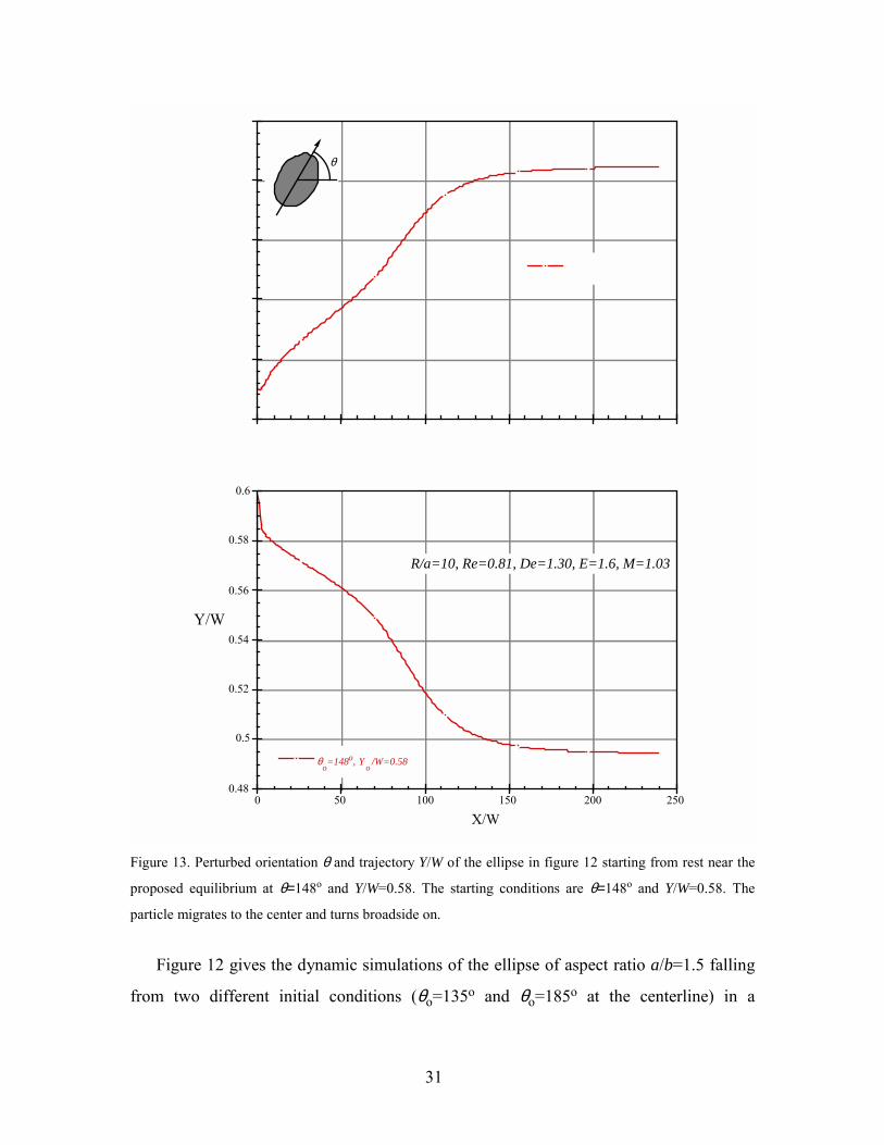
Figure 13. Perturbed orientation θ and trajectory Y/W of the ellipse in figure 12 starting from rest near the
proposed equilibrium at θ=148o and Y/W=0.58. The starting conditions are θ=148o and Y/W=0.58. The
particle migrates to the center and turns broadside on.
Figure 12 gives the dynamic simulations of the ellipse of aspect ratio a/b=1.5 falling
from two different initial conditions (θo=135o and θo=185o at the centerline) in a
32
Maxwell fluid. The numerical results show that the particle turns to have an equilibrium
tilted orientation (θ=148o) with an off-center position (Y/W=0.58). However, the results
are definitely indecisive since the positions and orientation angles are still changing. In
fact, for this type of discrimination our numerical work is indecisive; numerical
inaccuracy in the computations is cumulative and long time results have to be interpreted
with care.
Fortunately, numerical methods can be used effectively to test the stability of
equilibria. Proposing then that θ=148o and Y/W=0.58 is a tilted equilibria, we may test for
stability by considering the evolution of a small perturbation of this equilibrium. In the
present case, we drop an ellipse from rest at Y/W=0.58 with θ0=148o and see how the
evolution evolves. The result is shown in figure 13; the perturbed trajectory migrates to
the centerline and the perturbed orientation to broadside-on. Returning now to the static
calculation we may verify that the only zero torque orientations at the channel center are
vertical and horizontal. The broadside-on position is stable to small perturbations when
M=1.03 and the vertical θ=90o at the channel center is unstable. We conclude that
M=1.03 is supercritical with respect to broadside-on turning of an ellipse which is stable
in the vertical position at E=1.6 when the Mach number is less than some critical value
near M=1.
10. Effects of the retardation and relaxation time ratio
Now we shall compare the response of an Oldroyd-B fluid with λ 2 λ 1 = 1 8 with an
upper convected Maxwell model λ 2 = 0 . ηλ 2 can be interpreted as an effective
Newtonian contribution to the total viscosity (Joseph 1990, chapter 18). To get positive
normal stresses and other physical properties from an Oldroyd-B fluid, λ 2 ≤ λ1 . The fluid
is Newtonian when λ 2 = λ1 and is most elastic when λ 2 = 0 . Inertia alone enters when
λ 2 = λ1 ; hence it ought to be and is true that inertial effects become more important as

33
λ 2 λ1 is increased from 0 to 1. The effect of increasing the retardation time λ2 at a fixed
value of λ1 is to make the fluid more Newtonian.
The value λ 2 λ 1 = 1 8 is commonly used in numerical studies for historical reasons
only. No one knows how to measure λ2 and there is no single real fluid for which it can
be said that λ 2 λ 1 = 1 8. Many rheologists think that they can put ηλ 2 equal to the
solvent viscosity in a polymeric solution as was done by Rouse. This doubtful proposition
has no foundation in experiments and in any case λ 2 λ 1 ≠ 1 8. Joseph (1990) has argued
that the effective Newtonian viscosity ηλ 2 is a permanent memory relaxed elastic
modes.
Some comparisons of Oldroyd-B fluids with λ 2 λ 1 = 1 8 and λ 2 = 0 are exhibited in
figure 14. Figure 14(a) shows E=1.2 is above the critical elasticity number when λ 2 = 0
and is below the critical E when λ 2 λ 1 = 1 8. The critical E appears to be an increasing
function of λ 2 λ1 ; there is more broadside turning when the fluid is closer to Newtonian;
hence E=1.2 is below the critical E when R/a=10 and λ 2 λ 1 = 1 8. Figure 14(b) shows
that inertia turns a long particle broadside to the stream even in a Maxwell fluid when the
effect of elasticity is not large enough (E=0.8). If we eliminate inertia by putting the
Reynolds number Re to zero so E goes to infinity, the long particle rotates rapidly into a
vertical orientation. Without inertia, the normal stresses produce a torque which rotates
the particle straight-down.

34
θ
θ
Figure 14. Comparison of the orientation of falling ellipses in a Maxwell fluid λ2=0 to an Oldroyd-B fluid
with λ2/λ1=1/8. (R/a=10, a/b=1.5). Here M is much less than one and vertical and horizontal orientations
depend on the critical elasticity number which is higher when λ2/λ1=1/8. (a) The particle settles with its
longside vertical when E is above the critical ; (b) the same particle rotates to horizontal when E is below
critical but to vertical when inertia is suppressed (E=∞).

35
θ
0.48
0.5
0.52
0.54
0.56
0.58
0.6
Y/W
0 20 40 60 80 100
X/W
Re=0.44, De=0.18, E=0.40, M=0.08Re=0.44, De=0.35, E=0.80, M=0.39Re=0.44, De=0.53, E=1.20, M=0.49Re=0.48, De=0.61, E=1.28, M=0.54Re=0.49, De=0.67, E=1.36, M=0.57Re=0.49, De=0.78, E=1.60, M=0.62Re=0.46, De=1.85, E=4.00, M=0.92
Figure 15. Orientation angle and trajectory of an ellipse as a function of fall distance for different elasticitynumber corresponding to a fixed Reynolds number (Re≈0.47) in an Oldroyd-B fluid with λ2/λ1=1/8 when
R/a=10 and a/b=1.5.

36
11. Sedimentation of ellipses when λλλλ 2 λλλλ 1 = 1 8
We did a rather large number of computations for this case before taking up the case
λ 2 λ 1 = 0 . Here we shall summarize the results of this early study.
11.1. Critical elasticity number E
In figure 15 we plotted the orientation and trajectory of subcritical sedimentation of
an ellipse of aspect ratio a/b=1.5 in the case specified in the caption of that figure. We
kept Re fixed and changed De by changing the relaxation time λ1. This figure suggests
that the critical E for R/a=10 when λ 2 λ 1 = 1 8 is between 1.20 and 1.28. This is a value
slightly larger than when λ 2 λ 1 = 0 . The elliptic partilces eventually turn vertical or
horizontal; this can be shown by stability studies of the type described in section 9. The
critical M for broadside-on falling is expected to be larger than for the Maxwell model.
11.2. Streamlines and dynamics of turning ellipses
Streamlines in a coordinate system on the ellipse under conditions specified in figure
15 are shown in figures 16 and 17. Figure 16 is for a high De=1.85 and E=4.0; figure
16(a) shows the particle turning to the vertical equilibrium shown in figure 16(b). Clearly
the shear rates are large where the flow is fast, producing “high pressures” there, as
shown in figure 1. The normal stresses give rise to a large negative torque which turns the
ellipse clockwise, against the high pressure at the front stagnation point.

37
X/W=1.375 Y/W=0.532θ=108.6 o
X/W=14.32 Y/W=0.501θ=90.1 o
(a) (b)
Figure 16. Streamlines for the flow around an elliptic particle in an Oldroyd-B fluid under conditions
specified in figure 15, R/a=10, a/b=1.5, Re=0.46, De=1.85, E=4.0, M=0.92. (a) The particle is turning
clockwise; (b) the particle has reached an equilibrium in which the major axis is along the stream.
Figure 17 is for a smaller De=0.18 and E=0.40, the ellipse turns counter-clockwise
toward a horizontal equilibrium shown in figure 17(b). The high shear regions are now
located much closer to the two points on the major axis of the ellipse (figure 17(a)); the
compressive normal stresses generate a smaller negative torque on the particle and the
front stagnation pressure controls the turning, rotating the particle counter-clockwise.

38
X/W=1.38 Y/W=0.56θ=161.7 o
(a)X/W=34.6 Y/W=0.502θ=179.3 o
(b)
Figure 17. Streamlines for the flow around an elliptic particle in an Oldroyd-B fluid under conditions
specified in figure 15, R/a=10, a/b=1.5, Re=0.44, De=0.18, E=0.40, M=0.08. (a) The particle is turning
counter-clockwise; (b) the particle has reached an equilibrium in which the major axis is across the stream.
11.3. Effects of the particle aspect ratio a/b
Long thin ellipses turn vertical more readily than short fat ellipses. This suggests that
the critical elasticity number is a decreasing function of a/b, viscoelastic effects are
amplified. To study effects of viscoelasticity, we change the aspect ratio of the particle
a/b , keeping the particle weight constant. The fall velocity changes only slightly under
these conditions but particle tilts strongly to the vertical (θ=90o) as the aspect (or
thinness) ratio changes from 1.3 to 2.0, as shown in figure 18.

39
θ
0.48
0.5
0.52
0.54
0.56
0.58
0.6
Y/W
0.62
0 10 20 30 40
X/W50 60 70 80
a/b =1.3
a/b =1.5
a/b =1.7
a/b =2.0
Figure 18. Orientation θ and trajectory Y/W of ellipses with different aspect ratios falling in an Oldroyd-Bfluid with λ2/λ1=1/8 (R/a=10, Re=0.61, De=0.97, E=1.58, M=0.769).

40
11.4. Interaction of two ellipses
We compute two dynamic simulations of the settling of two elliptic particles a/b=1.5
in a channel R a =10 when ρf=1.0, ρs/ρf=1.0015, η=0.01, λ1=0.5 and λ 2 λ 1 = 1 8. In
one simulation in figure 19(a) the particles are dropped in tandem, in the other in figure
19(b) they are dropped side by side. The particles are distinguished by shading and equal
numbers are at equal time. Evidently, the particles wish to chain with their major axis
vertical. This is consistent with the notion that normal stresses are compressive and of
greatest strength where the shear stresses are greatest (see figure 1) as they are at
positions of the chain which are out of line, as in figure 19(b). A video animation of the
simulation shown in figure 19(b) can be seen on our web page. The simulation in figure
19(b) is terminated at number 15 because of collisions; the smallest distance between
particles becomes smaller than the elements in the mesh.

41
1
1
2
3
4
5
6
7
2
3
4
5
6
7
(a)
1 1
2
3
4
5
6
7
8
9
10
2
3
4
5
6
7
8
9
10
11
11
12
12
13
13
1414
1515
(b)Figure 19. The motion of two elliptic particles in an Oldroyd-B fluid (R/a=10, a/b=1.5, θο=90o). The
number on the particles shows different time step. (a) Particles are released one on top of the other; (b)
particles are released side by side.

42
12. Shear thinning
Joseph (1996) has argued, and Huang, Feng, Hu & Joseph (1996) have shown that the
shear thinning amplifies the effects of normal stresses. If the wall shear stress
τw = η( Ý γ w )Ý γ w is fixed at the places of high Ý γ w (as at points c in figure 1) Ý γ w goes up
when η( Ý γ w) decreases. Then, estimating the normal stress by
−Ψ1Ý γ w
2 = −η( Ý γ w )(λ1 − λ 2) Ý γ w2 = −τw
Ý γ w(λ 1 − λ 2 )
in an Oldroyd-B fluid we see that the normal stresses must be larger in the shear thinning
form of fluid.
θ
110
115
120
125
130
135
140
θ
145
150
0 10 20 30
X/W40 50 60
n=1.0, Re=0.64, De=0.97, M=0.79
n=0.8, Re=0.66, De=1.02, M=0.82
n=0.5, Re=0.69, De=1.07, M=0.86
Figure 20. The effect of shear thinning on the turning of an elliptic particle in an Oldroyd-B fluid (R/a=10,a/b=1.5, λ2/λ1=1/8, E=1.56).
Here we study shear thinning by using equation (4) with λ 3 λ 1 =1.0 and
η∞ η0 = 0.1, varying the shear thinning index n. Other parameters are R a =10 ,
a/b=1.5, λ 2 λ 1 = 1 / 8 and ρs/ρf=1.0022. We fixed the elasticity number near but less
than its critical value (E=1.56) so the effects of shear thinning can be seen clearly. For

43
n=1.0, the ellipse migrates to the center and turns broadside on. For n=0.8 and n=0.5 the
ellipse drifts to an off-center equilibrium with a certain angle of tilt.
θ
0.48
0.5
0.52
0.54
0.56
0.58
0.6
Y/W
0 10 20 30 40 50
X/W60
Y o /W=0.50, θo =181o
Y o /W=0.50, θo =170o
Y o /W=0.50, θo =135o
Y o /W=0.58, θo =120o
Y o /W=0.50, θo =91o
n=0.5, Re=0.69, De=1.07, M=0.86, E=1.56
Figure 21. Orientation θ and trajectory Y/W of an ellipse released with different initial positions and tilt
angles in an Oldroyd-B fluid with shear thinning. (λ 2 λ 1 = 1 8, R/a =10, a/b=1.5, Re=0.69, De=1.07,
E=1.56, M=0.86). The ellipse migrates to a stable equilibrium off-center with a certain tilt angle.

44
When the fluid does not shear thin, tilted off-center equilibria are unstable to small
perturbations where the equilibria and evolution of perturbations are computed by direct
simulation (see figure 13). The tilted solutions for n=0.8 and n=0.5 shown in figure 20
are stable to these same perturbations, as shown in figure 21. We are then forced to
conclude that tilted equilibrium solutions can be stable if the fluid shear thins.
We have already mentioned that it is appropriate not to claim too much from
simulations whose accuracy for long time evolution of the orientation and trajectory of a
falling ellipse is not perfect. With this reservation, we imagine that the action which
produces these off-center solutions depends on the walls, if a particle is displaced from
the center, the shear, hence the viscosity, is not the same at the left and right side of the
particle. This anisotropy of viscosity could be the new feature which opens the possibility
of stable tilt. Here, in figure 21, we show that the broadside-on equilibrium which was
stable when n=1.0, is unstable when n=0.5.
13. Conclusions
•••• Normal stresses due to inertia turn long bodies across the stream. Normal stresses
due to viscoelasticity turn long bodies along the stream. The orientation is determined by
a competition of normal stresses to inertia and viscoelasticity.
•••• The normal stresses associated with the extra stresses on moving rigid bodies
vanish. The normal stresses on rigid bodies due to all causes are contained in the pressure
alone. It may be true that the normal stresses on rigid bodies associated with extra
stresses vanish in all fluids in which the second normal stress vanishes.
•••• An ellipse falling in an Oldroyd-B fluid between plane walls can evolve into a time
dependent motion or steady falling. Stable steady flows are at the channel center and are
not tilted.
45
•••• A critical value of the elasticity number can be determined. For values of the
elasticity number below critical, the fluid is effectively Newtonian in the sense that the
final orientation is broadside on for all values of the fall velocity.
•••• For values of the elasticity number larger than critical, the ellipse finally settles with
its long axis vertical provided that it does not fall too fast.
•••• When the elasticity number is greater than critical, a critical Mach number can be
found. For Maxwell models the critical Mach number is close to one. When the fall
velocity is such that the Mach number is larger than critical, the ellipse falling vertically
will flip to horizontal.
•••• A non-zero critical elasticity number can be determined only for channels whose
walls are not too close. There is a critical blockage ratio (ratio of channel width to
particle diameter) below which no critical elasticity number can be determined. The
critical elasticity number is an increasing function of the blockage ratio R a tending to
some finite value as the distance between channel walls is increased.
•••• When the channel walls are close together (small blockage ratio), an ellipse settling
slowly in a Newtonian fluid will settle with its long axis vertical. This numerical result
was verified in an experiment. At faster speeds the ellipse settling in a Newtonian turns
broadside on.
•••• Tilted equilibria can also be generated by shear thinning which generates variable
flow induced viscosity which is not symmetric with respect to the falling particle.
•••• The effects of elasticity are enhanced in thinner ellipses. The critical elasticity
number is a decreasing function of the aspect ratio a b .
•••• The effect of increasing the retardation/relaxation time ratio λ 2 λ1 is to make the
fluid more Newtonian; it is Newtonian when this ratio is one.
There is a tendency for particles which fall slowly in viscoelastic fluids above the
critical elasticity number to line up with the longest line in the body with gravity; for a
square body or cube this long line is from vertex to vertex. This effect, which causes
46
cylinders with flat ends, or particles whose longest diameter is not centrally located, to tilt
is well documented in the experiments of Liu & Joseph (1993), of Joseph & Liu (1993)
and is explained theoretically by Joseph (1996). The sedimentations for these kinds of
particles have not yet computed by direct numerical simulation.
Acknowledgment: This work was partially supported by National Science Foundation
HPCC Grand Challenge grant (ESC-95-27123), by the NSF-CTS, by the US Army,
Mathematics, by the DOE, Department of Basic Energy Sciences, the Schlumberger
Foundation and by the Minnesota Supercomputer Institute.
ReferencesCaswell, B. 1967 Kinematics and stress on a surface of rest. Arch. Ratl. Mech. Anal.
26, 385-399.Chiba, K., Song, K. & Horikawa, A. 1986 Motion of a slender body in quiescent
polymer solutions. Rheol. Acta 25, 380-388.Crochet, M. J. & Delvaux, V. 1990 Numerical simulation of inertial viscoelastic flow,
with change of type. Material Instabilities in Continuum Mechanics and relatedMathematical Problems, edited by J. M. Ball (Clarendon, Oxford).
Cox, R. G. 1965 The steady motion of a particle of arbitrary shape at small Reynoldsnumbers. J. Fluid Mech. 23, 625-643.
Feng, J., Hu, H. H. & Joseph, D. D. 1994 Direct simulation of initial value problems forthe motion of solid bodies in a Newtonian fluid. Part. 1. Sedimentation. J. FluidMech. 261, 95-134.
Feng, J., Huang, P. Y. & Joseph, D. D. 1996 Dynamic simulation of sedimentation ofsolid particles in an Oldroyd-B fluid. J. Non-Newtonian Fluid Mech. 63, 63-88.
Feng, J., Joseph, D. D., Glowinski, R. & Pan, T. W. 1995 A three-dimensionalcomputation of the force and torque on an ellipsoid settling slowly through aviscoelastic fluid. J. Fluid Mech. 283, 1-16.
Giesekus, H.. 1963 Die Simultane Translations- und Rotationsbewegung einer Kugel ineiner elastoviskosen Flüssigkeit. Rheol. Acta 3, 59-71.
Hu, H. H. 1996 Direct simulation of flows of solid-liquid mixtures. Int. J. MultiphaseFlow. 22 (2), 335-352.
Hu, H. H. & Joseph, D. D. 1997 Simulation of particle motion in viscoelastic fluids. Inpreparation.

47
Hu, H. H., Joseph, D. D. & Crochet, M. J. 1992 Direct simulation of fluid particlemotions. Theoret. Comput. Fluid Dyn. 3, 285-306.
Huang, P. Y. & Feng, J. 1995 Wall effects on the flow of viscoelastic fluids around acircular cylinder. J. Non-Newtonian Fluid Mech. 60, 179-198.
Huang, P. Y., Feng, J., Hu, H. H. & Joseph, D. D. 1997 Direct simulation of the motionof solid particles in Couette and Poiseuille flows of viscoelastic fluids. J. Fluid Mech.(in press).
Huang, P. Y., Feng, J. & Joseph, D. D. 1994 The turning couples on an elliptic particlesettling in a vertical channel. J. Fluid Mech. 271, 1-16.
Joseph, D. D. 1996 Flow induced microstructure in Newtonian and viscoelastic fluids.Proc. of 5th World Congress of Chem. Eng., Particle Technology Track. San Diego.
Joseph, D. D. 1992 Bernoulli equation and the competition of elastic and inertialpressures in the potential flow of a second-order fluid. J. Non-Newtonian Fluid Mech.42, 385-389.
Joseph, D. D. 1990 Fluid Dynamics of Viscoelastic Liquids. Springer-Verlag.Joseph, D. D. 1985 Hyperbolic phenomena in the flow of viscoelastic fluids.
Viscoelasticity and Rheology, edited by A. S. Lodge, J. Nohel & M. Renardy(Academic, New York).
Joseph, D. D. & Feng, J. 1996 A note on the forces that move particles in a second-order fluid. J. Non-Newtonian Fluid Mech. 64, 299-302.
Joseph, D. D. & Liao, T. Y. 1994 Potential flows of viscous and viscoelastic fluids. J.Fluid Mech. 265, 1-23.
Joseph, D. D. & Liu, Y. J. 1993 Orientation of long bodies falling in a viscoelasticliquid. J. Rheol. 37, 961-983.
Leal, L. G. 1975 The slow motion of a slender rod-like particles in a second-order fluid.J. Fluid Mech. 69, 305-337.
Liu, Y. J. & Joseph, D. D. 1993 Sedimentation of particles in polymer solutions. J.Fluid Mech. 255, 565-595.
Milne-Thomson, L. M. 1968 Theoretical Hydrodynamics. Macmillan.Tanner, R. I. 1966 Plane creeping flows of incompressible second-order fluids. Phys.
Fluids 9, 1246-1247.Ultman, J. S. & Denn, M. M. 1970 Anomalous heat transfer and a wave phenomenon in
dilute polymer solutions. Trans. Soc. Rheol.. 14, 307-317.
Recommended
![Elliptic genera and elliptic cohomology - Long Island Universitymyweb.liu.edu/~dredden/EllipticGenera.pdf · the history of elliptic genera and elliptic cohomology, [Seg] explains](https://img.pdfslide.net/doc/110x75/5edc8698ad6a402d66673899/elliptic-genera-and-elliptic-cohomology-long-island-dreddenellipticgenerapdf.jpg)