WK 421 610
Type UREP10 WK 421 610 05.2012
05.2012
- 1 -
dm /min3
AAAA BBBB
aaaa bbbb
TTTT TTTTPPPPAAAA BBBBAAAA BBBBXXXX YYYY
1 23
4 56
7
up to 31,5 MPa up to 150NS10
Directional spool valve type UREP10
electro-hydraulically operated
DDDDAAAATTTTAAAA SSSSHHHHEEEEEEEETTTT ---- SSSSEEEERRRRVVVVIIIICCCCEEEE MAMAMAMANUANUANUANUALLLL
APPLICATION
DESCRIPTION OF OPERATION
Directional spool valves type UREP10UREP10UREP10UREP10………… electro-
hydraulically operated are intended for change in
direction of fluid flow in a system and thus it allows
to change direction of movement of a receiver -
mostly piston rod of a cylinder or hydraulic motor as
well to use functions: on and off. These directional spool valves are used for subplate mounting in any
position in a hydraulic system. The directional spool valve type UREP10UREP10UREP10UREP10………… is
complied with the regulations of directive
2006/95/WE2006/95/WE2006/95/WE2006/95/WE for the following voltages:
•50 50 50 50 –––– 250 V 250 V 250 V 250 V for AC AC AC AC
•75 75 75 75 –––– 250 V 250 V 250 V 250 V for DCDCDCDC
Main bore and annular ports PPPP, TTTT, AAAA, BBBB are made in the
housing (1) and connected to its subplate connection.
Directional valve is switched by shifting the spool (2)
into one end position. Various control functions are
dependent on the spool (2) which affects the change in
configuration of connections among ports PPPP, TTTT, AAAA, BBBB in
the housing (1). The spool (2) is shifted from its neutral
position by affecting pressure of hydraulic fluid
supplied via pilot valve (4) into one chamber of caps (3).
The pilot valve (4) – type WE6…WE6…WE6…WE6… is operated by means
of solenoids (5). The spool (2) is centered in neutral
position by means of springs (7). In case of failure, the
pilot valve (4) may be shifted manually by means of
manual overrides (6) – version UREP10…/…NNNN.
4UREP10 E 02/G24 N ET Z4

Type UREP10WK 421 610 05.2012 - 2 -
...UREP10.../...11110000... ...UREP10.../...SSSS...11110000...
9 8
Directional spool valves type UREP10...UREP10...UREP10...UREP10... may be provided
with the pilot choke adjustment (8) as well as with
accessories such as: spool stroke limiter (9) or or both
optional accessories. Detailed information concerning
depending on version of directional valve with
accessories given on page 9-10.
DESCRIPTION OF OPERATION
Ports A A A A, B B B B, P P P P 31, 31, 31, 31, 5 5 5 5 MMMMPPPPaaaa
Port TTTT
• pilot fluid return Y Y Y Y- exter- exter- exter- externnnnaaaallll 22225 5 5 5 MMMMPPPPaaaa
• pilot fluid return YYYY- - - - iiiinnnnternternternternaaaallll 2 2 2 21 1 1 1 MMMMPPPPaaaa
22221 1 1 1 MMMMPPPPaaaaMMMMaaaax cx cx cx coooonnnntrotrotrotrol presl presl presl presssssureureureure
MMMMiiiin cn cn cn coooonnnntrotrotrotrol presl presl presl presssssureureureure
recommended
max
Viscosity range
Fluid temperature range (in a tank)
Ambient temperature range
MMMMaaaax x x x operoperoperoperatatatatiiiing presng presng presng presssssureureureure
mineral oil
ReReReReqqqquuuuired fired fired fired f iiiiltrltrltrltratatatatiiiioooonnnn
Recommended filtration
up tup tup tup to o o o 11116666 µµµµmmmmup to 10 µm
Hydraulic fluid
Nominal fluid viscosity 2 o37 mm /s at temperature 55 C
22,8 up to 380 mm /so40 C up to 55 Co
o-20 C up to +70 Co
HydrHydrHydrHydraaaauuuullllic fic fic fic f lllluuuuidididid
- 20 C up to +50 Coo
0,0,0,0,5 5 5 5 MMMMPPPPaaaa
TECHNICAL DATA

Type UREP10 WK 421 610 05.2012- 3 -
TTTTooootatatatal tl tl tl time ime ime ime oooof spf spf spf spooooooool l l l sssshhhhififififtitititing frng frng frng from om om om neneneneuuuutratratratral tl tl tl to eo eo eo endndndnd
popopopossssititititiiiioooonnnn
TTTTooootatatatal tl tl tl time ime ime ime oooof spf spf spf spooooooool l l l sssshhhhififififtitititing frng frng frng fromomomom enenenendddd ttttoooo neneneneuuuutratratratrallll
popopopossssititititiiiioooonnnn
7 kg
with z 1 solenoid
6,4 kg
4WE6 Y Y Y Y ...
4WE6 J J J J ...
222233330000V V V V - - - - 55550000HHHHz z z z 111111110000V V V V - - - - 55550000HHHHzzzz11112222V V V V 22224444V V V V 111111110000VVVV
• 3-position directional valve (springs centered)
at pilot pressure p st = 10 MPa 40 ms ±10%
• 2-position directional valve (spring positioned) at pilot pressure p st = 10 MPa 50 ms ±10%
• 3-position directional valve (springs centered)
at pilot pressure p st = 10 MPa 50 ms ±10%
• 2-position directional valve (spring positioned) at pilot pressure p st = 10 MPa 60 ms ±10%
NNNNomomomomiiiinnnnaaaal l l l ssssuppuppuppupply ly ly ly vvvvooooltltltltage fage fage fage for or or or ssssoooolelelelennnnooooididididssssDDDDCCCC AAAACCCC (plug-in connector with rectifier)
Supply voltage tolerance ±10%
IIIInnnnssssuuuullllatatatatiiiioooonnnn I I I IP P P P 66665555
Power requirement (DC) 3 3 3 30000 W
Temperature of solenoid coil max 150 Co
PPPPiiiilllloooot vt vt vt vaaaallllveveveve
Type of pilot valve
• for 3-position directional valve
(springs centered)
• for 2-position directional valve e (spring positioned)
Weightwith 2 solenoids
TECHNICAL DATA
ASSEMBLY AND APPLICATION REQUIREMENTS
4.4.4.4. It is forbidden to It is forbidden to It is forbidden to It is forbidden to applyapplyapplyapply directional directional directional directional spool spool spool spool
valve valve valve valve ifififif the plug the plug the plug the plug----inininin----connectorconnectorconnectorconnector is not pr is not pr is not pr is not properoperoperoperly ly ly ly
tightened to the solenoid sockettightened to the solenoid sockettightened to the solenoid sockettightened to the solenoid socket and is not and is not and is not and is not
secured by screwing boltsecured by screwing boltsecured by screwing boltsecured by screwing bolt tig tig tig tighhhhtlytlytlytly....
5.5.5.5. Due to heating solenoid coils, directional Due to heating solenoid coils, directional Due to heating solenoid coils, directional Due to heating solenoid coils, directional
spool spool spool spool valves should be valves should be valves should be valves should be placed in orderplaced in orderplaced in orderplaced in order to to to to
eleleleliminate the possibility of incidental touch iminate the possibility of incidental touch iminate the possibility of incidental touch iminate the possibility of incidental touch
while using, or, they should be equipped while using, or, they should be equipped while using, or, they should be equipped while using, or, they should be equipped
with the coil covers with the coil covers with the coil covers with the coil covers (in accordancein accordancein accordancein accordance withwithwithwith thethethethe
EuropeanEuropeanEuropeanEuropean standards standards standards standards PNPNPNPN ---- EN EN EN EN ISOISOISOISO 13732137321373213732----1111
andandandand PNPNPNPN ---- EN 982EN 982EN 982EN 982)....
1.1.1.1. Only valve working properly and suitably Only valve working properly and suitably Only valve working properly and suitably Only valve working properly and suitably
installed may be connected to an electric installed may be connected to an electric installed may be connected to an electric installed may be connected to an electric
system. Only skilled workers are allowed to system. Only skilled workers are allowed to system. Only skilled workers are allowed to system. Only skilled workers are allowed to
connect and disconnect electric system.connect and disconnect electric system.connect and disconnect electric system.connect and disconnect electric system.
2.2.2.2. Ground connection Ground connection Ground connection Ground connection ( ) must must must must bebebebe connected connected connected connected
with protective earth wire with protective earth wire with protective earth wire with protective earth wire ( PEPEPEPE ) in supply in supply in supply in supply
system according to system according to system according to system according to appropriate appropriate appropriate appropriate instructions.instructions.instructions.instructions.
3.3.3.3. It is forbidden to It is forbidden to It is forbidden to It is forbidden to applyapplyapplyapply directional directional directional directional spool spool spool spool valve valve valve valve if if if if
the supply cable in thethe supply cable in thethe supply cable in thethe supply cable in the gland gland gland gland of plugof plugof plugof plug----inininin----
connector connector connector connector is not is not is not is not properly tightenedproperly tightenedproperly tightenedproperly tightened....

Type UREP10WK 421 610 05.2012 - 4 -
b, Y
A B
P TX Y
a b
a, X a b
a b
A B
P T
a b
a b
A B
P T
a b
X
b, Y
A B
P TX Y
a b
a, X a b
a b
A B
P T
a b
Y
b, Y
A B
P TX Y
a b
a, X a b
a b
A B
P T
a b
X Y
b, Y
A B
P TX Y
a b
a, X a bb, Y
A B
P TX Y
a b
a, X a b0
a b
A B
P T
a b0
Y
a b
A B
P T
a b0
X
a b
A B
P T
a b0
YX
b, Y
A B
P TX Y
a b
a, X a b0
b, Y
A B
P TX Y
a b
a, X a b0
b, Y
A B
P TX Y
a b
a, X a b0
a b
A B
P T
a b0
3-position directional valves with springs centered
spool at 0000 position (spool schemes: EEEE, FFFF, GGGG, HHHH, JJJJ, LLLL,
MMMM, UUUU, WWWW)
exexexextttternaernaernaernallll supply XXXX ; exexexextttternaernaernaernallll drain Y Y Y Y
version ...UREP10.../...
iiiinnnntttternaernaernaernallll supply XXXX ; exexexextttternaernaernaernallll drain Y Y Y Y
version ...UREP10.../...EEEE...
iiiinnnnternternternternaaaallll supply XXXX ; iiiinnnntttternaernaernaernallll drain Y Y Y Y
version ...UREP10.../...EEEETTTT...
exexexextttternaernaernaernallll supply XXXX ; iiiinnnntttternaernaernaernallll drain Y Y Y Y
version ...UREP10.../...TTTT...
2-position directional valves with spring positioned
spool (spool schemes: CCCC, DDDD)
exexexextttternaernaernaernallll supply XXXX ; exexexextttternaernaernaernallll drain Y Y Y Y
version ...UREP10.../...
iiiinnnntttternaernaernaernallll supply XXXX ; exexexextttternaernaernaernallll drain Y Y Y Y
version ...UREP10.../...EEEE...
iiiinnnnternternternternaaaallll supply XXXX ; iiiinnnntttternaernaernaernallll drain Y Y Y Y
version ...UREP10.../...EEEETTTT...
exexexextttternaernaernaernallll supply XXXX ; iiiinnnntttternaernaernaernallll drain Y Y Y Y
version ...UREP10.../...TTTT...
SCHEMES
SSSSimpimpimpimpllllifififified ied ied ied aaaand detnd detnd detnd detaaaaiiiiled led led led hydrhydrhydrhydraaaauuuullllic scic scic scic schemes fhemes fhemes fhemes forororor
directdirectdirectdirect iiiioooonnnnaaaal l l l vvvvaaaallllves ves ves ves wwwwitititith h h h vvvvarararariiiioooouuuus ps ps ps piiiilllloooot st st st suppuppuppupplylylyly (XXXX)
aaaand pnd pnd pnd piiiilllloooot drat drat drat draiiiinnnn (YYYY)
Type UREP10 WK 421 610 05.2012- 5 -
E
F
H
J
L
MMMM
U
WWWW
C
D
A B
P T
aaaa bbbb0000
A B
P T
aaaa bbbb0000
A B
P T
aaaa bbbb
A B
P T
aaaa bbbb
G
working and
indirect positions
working
positionsworking and
indirect positions
working
positions
3333-p-p-p-poooossssititititiiiioooonnnn 2222-p-p-p-poooossssititititiiiioooonnnn
GrGrGrGrapapapaphhhhicicicic ssssymbymbymbymboooollllssss fffforororor spspspspoooooooollllssss
SCHEMES
NOTESNOTESNOTESNOTES:
For 3333----position directional control valvesposition directional control valvesposition directional control valvesposition directional control valves, the position of
directional control valve is executed by individual
spools acc. to schemes of connections, constituting
reflection of schemes reflection of schemes reflection of schemes reflection of schemes presented above is obtained by
alternative connection of plugsalternative connection of plugsalternative connection of plugsalternative connection of plugs for suitable solenoid
coils of preliminary directional valve.
The spools type in bold are preferred versions in short The spools type in bold are preferred versions in short The spools type in bold are preferred versions in short The spools type in bold are preferred versions in short
delivery time.delivery time.delivery time.delivery time.

Type UREP10WK 421 610 05.2012 - 6 -
14
0,63
r 0,01/100 mm
aaaa
AAAA
bbbb
BBBB
TTTT TTTTAAAA BBBB
TTTT
PPPPYYYYXXXX AAAA BBBB
AAAA BBBBTTTT
30
86 (9
5)
15
91
2 43 65 8
7 12
11
S6
PG11
TTTT TTTT
PPPP
AAAA BBBB
AAAA BBBB
XXXX YYYY
3,2*16,7
27
37,350,8
54
6,3
21,4
32,5
46
115 (min)
13
M6 depth 12 - 4 holes
O11,2 (max) - 4 holes*
(P, T, A, B)
70 (m
in)
8
11
6290
70
218
180
120 30
5482
46
O6,6 - 4 holes
26
10
3-position versions springs centered
OVERALL AND CONNECTION DIMENSIONS
1 - 3333-p-p-p-poooositisitisitisitioooonnnn main directional valve (spool schemes:
EEEE, FFFF, GGGG, HHHH, JJJJ, L L L L, MMMM, UUUU, WWWW - on page 5)
2 - 3333-p-p-p-poooositisitisitisitioooonnnn directional valve (pilot valve) type WWWWEEEE6666JJJJ............
3 - Solenoid aaaa
4 - Solenoid bbbb
5 - Plug-in-connector AAAA - I I I ISSSSO O O O 4444444400000000 (DIN 43650 - A)
6 - Plug-in-connector BBBB - IIIISSSSO O O O 4444444400000000 (DIN 43650 - A)
7 - Manual override
8 - Pilot choke adjustment (optional accessories)
9 - Sealing ring oooo-ring -ring -ring -ring 11112,2,2,2,44442 x 2 x 2 x 2 x 1,1,1,1,77778888 - 5 pcs/kit
(PPPP,TTTT ,TTTT , AAAA, BBBB)
10 - Sealing ring oooo-rin-rin-rin-ringggg 9999,,,,22225555 x x x x 1111,,,,77778888 - 2 pcs/kit (XXXX,YYYY)
11 - Dimension for electrical connection for DCDCDCDC
12 - Dimension for electrical connection for ACACACAC
(plug-in-connector with rectifier)
13 - Porting pattern - configuration of surface holes in
subplate in accordance with the following
standards:
• C C C CEEEETOTOTOTOP P P P RRRRP P P P 111122221111HHHH - identified by CCCCEEEETOTOTOTOPPPP 4.2-4-RRRR00005555
(nominal size C C C CEEEETOTOTOTOP P P P 00005)5)5)5)
• IIIISSSSO O O O 4444444400001111 - identified by IIIISSSSO O O O 4444444400001111-00005555-05-0-05
mounting bolts MMMM6666 x x x x 33335555 - - - - 11110000....9999 in accordance with
PPPPN -N -N -N - EEEEN N N N IIIISSSSO O O O 4444777766662222 - 4 pcs/kit
tightening torque Md Md Md Md = = = = 1 1 1 15 5 5 5 NmNmNmNm
NONONONOTTTTEEEE::::
(****) - It is sufficient connections withj only one hole TTTT
from side port AAAA or BBBB - the port TTTT and TTTT are
together connected by channel in housing of
directional valve
14 - Subplate surface required
BBBBAAAA
AAAA BBBB
O6,3 (max) 2 holes (X, Y)

Type UREP10 WK 421 610 05.2012- 7 -
TTTT TTTTAAAA BBBB
bbbb
BBBB
91
2 346
8
TTTT
PPPPYYYY
XXXX
AAAA BBBB
AAAA BBBBTTTT
54
46
O6,6 - 4 holes82
30
86 (95)
15
5 10
9
S6
PG11
90
70
30120
180
200
26
2-position versions spring positioned
OVERALL AND CONNECTION DIMENSIONS
1 - 2222-p-p-p-poooositisitisitisitioooonnnn main directional valve (spool schemes:
C C C C , DDDD - on page 5)
2 - 2222-p-p-p-poooositisitisitisitioooonnnn directional valve (pilot valve) type WWWWEEEE6Y..6Y..6Y..6Y......
3 - Solenoid bbbb
4 - Plug-in-connector BBBB - IIIISSSSO O O O 4444444400000000 (DIN 43650 - A)
5 - Manual override
6 - Pilot choke adjustment (optional accessories)
7 - Sealing ring oooo-ring -ring -ring -ring 11112,2,2,2,44442 x 2 x 2 x 2 x 1,1,1,1,77778888 - 5 pcs/kit
(PPPP,TTTT ,TTTT , AAAA, BBBB)
8 - Sealing ring oooo-rin-rin-rin-ringggg 9999,,,,22225555 x x x x 1111,,,,77778888 - 2 pcs/kit (XXXX, YYYY)
9 - Dimension for electrical connection for DCDCDCDC
10 - Dimension for electrical connection for ACACACAC
(plug-in-connector with rectifier)
11 - Porting pattern - configuration of surface holes in
subplate in accordance with the following
standards:
• C C C CEEEETOTOTOTOP P P P RRRRP P P P 111122221111HHHH - identified by CCCCEEEETOTOTOTOPPPP 4.2-4-RRRR00005555
(nominal size C C C CEEEETOTOTOTOP P P P 00005555)
• IIIISSSSO O O O 4444444400001111 - identified by IIIISSSSO O O O 4444444400001111-00005555-05-0-05
mounting bolts MMMM6666 x x x x 33335555 - - - - 11110000....9999 in accordance with
PPPPN -N -N -N - EEEEN N N N IIIISSSSO O O O 4444777766662222 - 4 pcs/kit
tightening torque Md Md Md Md = = = = 1 1 1 15 5 5 5 NmNmNmNm
NONONONOTTTTEEEE::::
(****) - It is sufficient connections withj only one hole TTTT
from side port AAAA or BBBB - the port TTTT and TTTT are
together connected by channel in housing of
directional valve
12 - Subplate surface required
AAAA BBBB
AAAA BBBB
12
0,63
r 0,01/100 mm
TTTT TTTT
PPPP
AAAA BBBB
AAAA BBBB
XXXX YYYY
3,2*16,7
27
37,350,8
54
6,3
21,4
32,5
46
115 (min)
11
M6 depth 12 - 4 holes
O11,2 (max) - 4 holes*
(P, T, A, B)
70 (min)
8
11
62
O6,3 (max) 2 holes (X, Y)

Type UREP10WK 421 610 05.2012 - 8 -
T T T T
PPPP
PPPP TTTT
XXXX YYYY
1
3 4
2
In version …UREP10.../... the pilot flow is taken externally
system through port XXXX.
Drainage pilot flow is through independent port YYYY to tank.
Two the hole screws plugs (3) and (4) in ports XXXX, YYYY must
be mounted in the position like given on the drawing.
In version …UREP10.../...ETETETET... the pilot flow is taken
internally from port PPPP main directional valve.
Drainage pilot flow is through internally port TTTT to tank.
The hole screws plugs (3) and (4) is dismounted. Ports XXXX
and YYYY in a subplate must be plugged.
In version …UREP10.../...EEEE... the pilot flow is taken
internally from port PPPP main directional valve. Drainage pilot flow is through independent port YYYY to tank.
The hole screw plug (3) is dismounted, the hole screw
plug (4) is mounted. Port XXXX in a subplate should be
plugged.
In version …UREP10.../...TTTT... the pilot flow is taken
internally from port PPPP main directional valve. Drainage
pilot flow is through internally port T T T T to tank. The hole
screw plug (3) is mounted, the hole screw plug (4) is
dismounted. Port YYYY in a subplate should be plugged.
PILOT OIL SUPPLY AND PILOT OIL DRAIN
Pilot oil supply XXXX – external external external external
pilot oil drain YYYY – externalexternalexternalexternal
version …UREP10…/…
Pilot oil supply X X X X – iiiinternalnternalnternalnternal
pilot oil drain YYYY – externalexternalexternalexternal
version …UREP10…/…EEEE…
Pilot oil supply XXXX – internalinternalinternalinternal
pilot oil drain YYYY – internalinternalinternalinternal
version …UREP10…/…EEEETTTT…
Pilot oil supply XXXX – externalexternalexternalexternal
pilot oil drain YYYY – internalinternalinternalinternal
version …UREP10…/…TTTT…
Pilot oil supply
(XXXX) – externalexternalexternalexternal - the plug (3) is mounted
(XXXX) – ininininternalternalternalternal - the plug (3) is dismounted
1 - Main valve body
2 - Pilot valve body
3 - Hole screw plug MMMM5 5 5 5 x x x x 6 6 6 6 ---- pilot oil supply (XXXX)
4 - Hole screw plug MMMM5555 x x x x 6666 - - - - pilot oil drain (YYYY)
Pilot oil drain
(YYYY) – externalexternalexternalexternal - the plug (4) is mounted
(YYYY) – ininininternalternalternalternal - the plug (4) is dismounted

Type UREP10 WK 421 610 05.2012- 9 -
versions: ...UREP10.../...SSSS...
...UREP10.../...SSSS2222...
1
2
5
34
... ... ... ...UREP10.../...SSSS2222... ... ... ... ...UREP10.../...SSSS...
PPPP
2
1
3
Directional spool valves type UREP10UREP10UREP10UREP10… may be
optionally provided with pilot choke adjustment (3)
which allows to adjust switching time of directional
spool valve.
Rotation of the adjusting screw (4) clockwise increases
and counterclockwise decreases switching time of the
valve.
The change of adjustment method of switching time
(flow throttling): on inlet - version …UREP10.../…SSSS... or
on outlet - version …UREP10.../…S2S2S2S2... is made while
mounting by rotating the pilot choke adjustment (3) by
180 degrees around its longitudinal axis.
Pilot choke adjustment
ACCESSORIES FOR STANDARD
DIRECTIONAL VALVE
The pilot choke adjustment (3) is fixed by means
of bolts M5 x 8M5 x 8M5 x 8M5 x 80 0 0 0 ---- 10.910.910.910.9 - 4 pcs/kit in accordance
with PN PN PN PN ---- EN ISO 4762EN ISO 4762EN ISO 4762EN ISO 4762 with tightening torque of
MdMdMdMd = 5 Nm5 Nm5 Nm5 Nm.
1 - Main valve
2 - Pilot valve
3 - Pilot choke adjustment with adjustment of switching
time on inlet
4 - Assembly method of pilot choke adjustment with
adjustment of switching time on outlet
5 - Adjusting screw
Throttle insert
version ...UREP10.../...B.B.B.B...
1 - Main valve body
2 - Pilot valve body
3 - Throttle insert
Directional valves type UREP10UREP10UREP10UREP10………… may be equipped
with throttle insert (3) in port PPPP in pilot valve (2) which
allows to delaydelaydelaydelay switching timeswitching timeswitching timeswitching time of the main valve.

Type UREP10WK 421 610 05.2012 - 10 -
...UREP10.../...11110.0.0.0...
3 24 1
version ...UREP10.../...11110000...
280 (max)
113 (max)
Mounting optionsMounting optionsMounting optionsMounting options
Directional valves type UREP10…UREP10…UREP10…UREP10… with 3333----positionpositionpositionposition
spoolsspoolsspoolsspools, spring centeredspring centeredspring centeredspring centered may be equipped with stroke
limiter, it may be mounted on canal AAAA or BBBB (version
…UREP10.../...10101010...).
OPTIONAL ACCESSORIES FOR DIRECTIONAL
VALVE
Stroke limiter
Adjustment of the stroke of the main spool is by
rotating the pin (3) and securing with locknut (4).
Rotating the pin (3) clockwise reduces the stroke of the
main spool (2). While adjusting the stroke the control
chamber must be at zero pressure.
1 - Main valve
2 - Stroke limiter body
3 - Pin
4 - Locknut
OOOOververververaaaalllll dl dl dl dimeimeimeimennnnssssiiiioooonnnnssss
Type UREP10 WK 421 610 05.2012- 11 -
∆∆ ∆∆ p [M
p [M
p [M
p [M
Pa]
Pa]
Pa]
Pa]
0000 55550000 111100000000
0,0,0,0,2222
0,0,0,0,4444
0,0,0,0,6666
0,0,0,0,8888
1,1,1,1,0000
QQQQ [dm [dm [dm [dm /mi/mi/mi/min]n]n]n]3333
111155550000
3
6
5
4
1
2
flow direction
PPPP →→→→ AAAA PPPP →→→→ B B B B AAAA →→→→TTTT BBBB →→→→TTTT
DDDD
EEEE
FFFF
GGGG
HHHH
JJJJ
LLLL
MMMM
UUUU
WWWW
11111111
33334444
66666666 6666
(1)
3333 5555
2222
1111
5555
1111 11111111 1111
44442222
1111
5555
5555 5555 2222 3333
2222 4444
1111 1111 33332222
PPPP →→→→ TTTT
66666666 6666 3333 5555
44446666 (2)
(1)(3)
1111 1111 33332222
1111 1111 (1)(3)
1111 1111
2222 22221111 1111
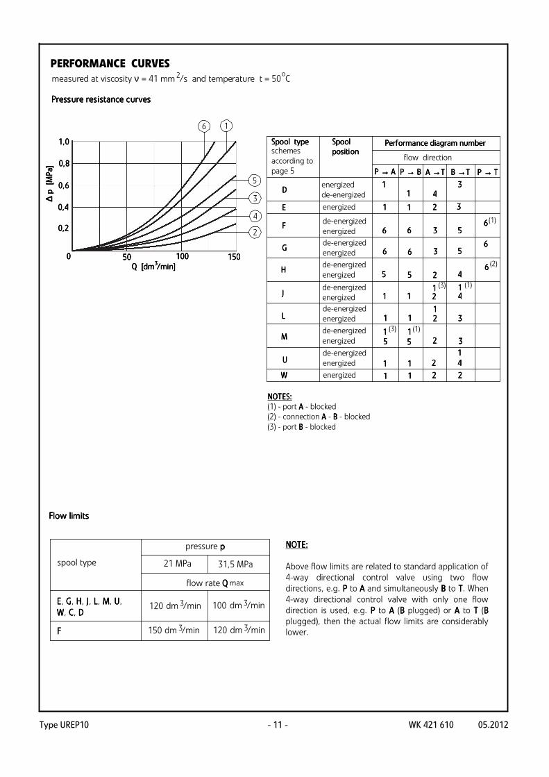
NOTNOTNOTNOTEEEES:S:S:S:
(1) - port AAAA - blocked
(2) - connection AAAA - BBBB - blocked
(3) - port BBBB - blocked
SpoSpoSpoSpool typeol typeol typeol type PerfPerfPerfPerformaormaormaormance diagram numbernce diagram numbernce diagram numbernce diagram numberschemes
according to
page 5
SpoSpoSpoSpoolololol
positipositipositipositioooonnnn
energized
de-energized
energized
de-energized
energized
de-energized
energized
de-energized
energized
de-energized
energized
de-energized
energized
de-energized
energized
de-energized
energized
energized
EEEE, GGGG, HHHH, J J J J, L L L L, MMMM, U U U U,
WWWW, C C C C, D D D D
21 MPa 31,5 MPa
pressure pppp
120 100
150FFFF
spool type
120
flow rate QQQQmax
dm /min3
dm /min3
dm /min3
dm /min3
PERFORMANCE CURVES
measured at viscosity ν = 41 mm /s and temperature t = 50 C2 o
PressPressPressPressure resure resure resure res iiiiststststaaaance cnce cnce cnce cururururvesvesvesves
FlFlFlFloooow w w w llllimimimimititititssss
NOTE: NOTE: NOTE: NOTE:
Above flow limits are related to standard application of
4-way directional control valve using two flow
directions, e.g. PPPP to A A A A and simultaneously BBBB to TTTT. When
4-way directional control valve with only one flow
direction is used, e.g. PPPP to AAAA (BBBB plugged) or AAAA to TTTT (BBBB
plugged), then the actual flow limits are considerably
lower.

Type UREP10WK 421 610 05.2012 - 12 -
UREP 10
Supply voltage for solenoids at pilot valve
12 V DC = G 12
24 V DC = G 24
110 V DC = G 110
110 V AC 50 Hz (plug-in-connector with rectifier) = W 110 R
230 V AC 50 Hz (plug-in-connector with rectifier) =W 230 R
Pilot oil supply and pilot oil drain
external pilot oil supply, external pilot oil drain = no designation
internal pilot oil supply, external pilot oil drain = E
internal pilot oil supply, internal pilot oil drain = ET
external pilot oil supply, internal pilot oil drain = T
Switching time adjustment
without switching time adjustment = no designation
switching time adjustment as meter-in control = S
switching time adjustment as meter-out control = S2
Type of the main spool
spool schemes - according to page 5
Series number
(00-09) - installation and connection dimensions unchanged = 0X
series 02 = 02
Nominal size (NS)
NS10 = 10
Manual override
solenoids without manual override = no designation
solenoids with manual override = N
Throttle insert in port P of the pilot valve
without throttle insert = no designation
throttle insert φ 0,8 = B 08
throttle insert φ 1,0 = B 10
throttle insert φ 1,2 = B 12
Electrical connection
plug-in-connector ISO 4400 type without LED = Z4
plug-in-connector ISO 4400 type with LED = Z4L
Accessories
without accessories = no designation
stroke limiter on valve ends AAAA and BBBB = 10
4
HOW TO ORDER

Type UREP10 WK 421 610 05.2012- 13 -
* Further requirements in clear text
(to be agreed with the manufacturer)
Sealing
NBR (for fluids on mineral oil base) = no designation
FKM (for fluids on phosphate ester base) = V
HOW TO ORDER
NNNNOOOOTTTTEEEES:S:S:S:
The directional spool valve should be ordered according to the above coding.
TTTThe he he he symbosymbosymbosymbolllls s s s iiiin bn bn bn boooold ld ld ld are preferred versare preferred versare preferred versare preferred vers iiiioooonnnns s s s iiiin n n n sssshhhhort deort deort deort delllliiiivery tvery tvery tvery t ime.ime.ime.ime.
Coding example: 4 UREP 10 E 02/G24 N ET Z4

Type UREP10WK 421 610 05.2012
PONAR Wadowice S.A.
ul. Wojska Polskiego 29
34-100 Wadowice
tel. +48 33 488 21 00 fax.+48 33 488 21 03
www.ponar-wadowice.pl
- 14 -
Recommended