Distributed Systems Concepts
Ch. 10 and 14-17

Figure 10.1Skew between computer clocks
in a distributed system
Network

Figure 10.2Clock synchronization using a
time server
mr
mtp Time server,S

Figure 10.3An example synchronization
subnet in an NTP implementation
1
2
3
2
3 3
Note: Arrows denote synchronization control, numbers denote strata.

Figure 10.4Messages exchanged between
a pair of NTP peers
Ti
Ti-1Ti-2
Ti- 3
Server B
Server A
Time
m m'
Time

Figure 10.5Events occurring at three
processesp1
p2
p3
a b
c d
e f
m1
m2
Physicaltime
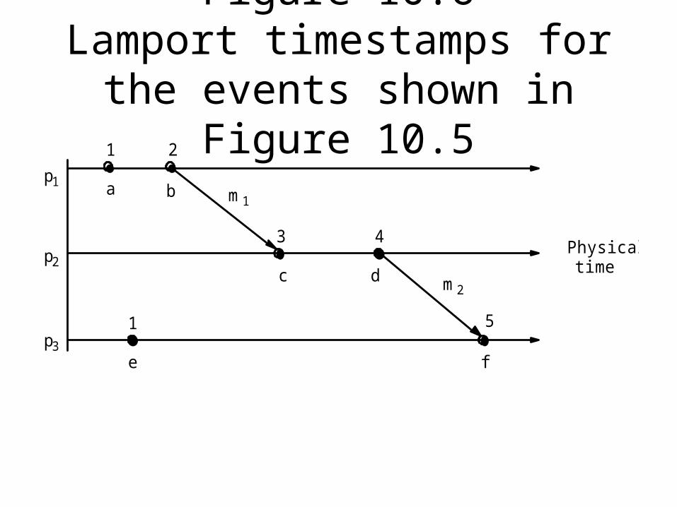
Figure 10.6Lamport timestamps for the events shown in Figure 10.5
a b
c d
e f
m1
m2
21
3 4
51
p1
p2
p3
Physical time

Figure 10.7Vector timestamps for the
events shown in Figure 10.5
a b
c d
e f
m1
m2
(2,0,0)(1,0,0)
(2,1,0) (2,2,0)
(2,2,2)(0,0,1)
p1
p2
p3
Physical time

Figure 10.8Detecting global properties
p2p1
message
garbage object
objectreference
a. Garbage collection
p2p1 wait-for
wait-forb. Deadlock
p2p1
activatepassive passivec. Termination

Figure 10.9Cuts
m1 m2
p1
p2Physical
time
e10
Consistent cutInconsistent cut
e11
e12
e13
e20
e 21
e 22
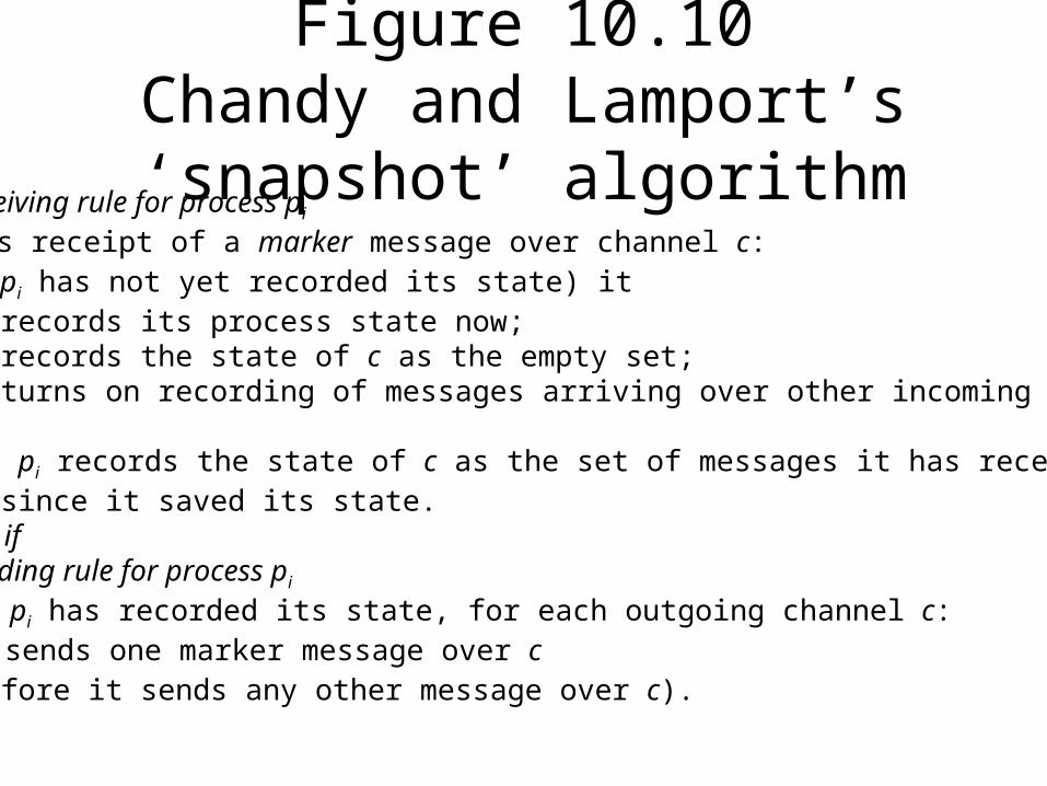
Figure 10.10Chandy and Lamport’s
‘snapshot’ algorithmMarker receiving rule for process pi
On pi’s receipt of a marker message over channel c:if (pi has not yet recorded its state) it
records its process state now;records the state of c as the empty set;turns on recording of messages arriving over other incoming channels;
else pi records the state of c as the set of messages it has received over c since it saved its state.
end ifMarker sending rule for process pi
After pi has recorded its state, for each outgoing channel c: pi sends one marker message over c (before it sends any other message over c).

Figure 10.11Two processes and their initial
states
p1 p2c2
c1
account widgets
$1000 (none)
account widgets
$50 2000

Figure 10.12The execution of the processes
in Figure 10.11p1 p2(empty)<$1000, 0> <$50, 2000>
(empty)
c2
c1
1. Global state S 0
2. Global state S 1
3. Global state S 2
4. Global state S 3
p1 p2(Order 10, $100), M<$900, 0> <$50, 2000>
(empty)
c2
c1
p1 p2(Order 10, $100), M<$900, 0> <$50, 1995>
(five widgets)
c2
c1
p1 p2(Order 10, $100)<$900, 5> <$50, 1995>
(empty)
c2
c1
(M = marker message)
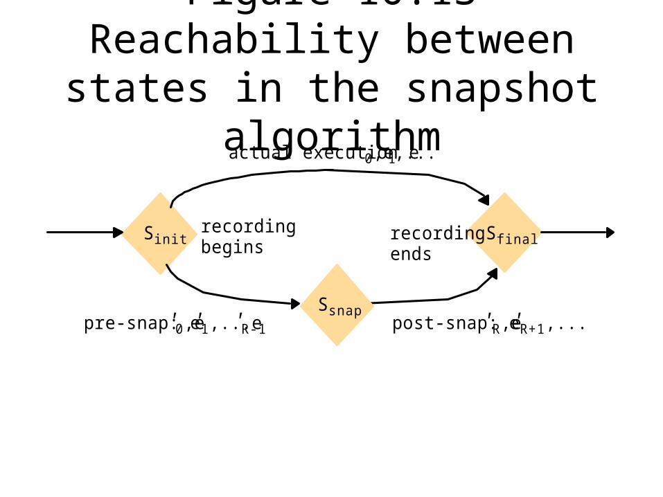
Figure 10.13Reachability between states in
the snapshot algorithm
Sinit Sfinal
Ssnap
actual execution e 0,e1,...
recording recording begins ends
pre-snap: e '0,e'1,...e'R-1 post-snap: e'R,e'R+1,...

Figure 10.14Vector timestamps and variable
values for the execution of Figure 10.9
m1 m2
p1
p2Physical
time
Cut C1
(1,0) (2,0) (4,3)
(2,1) (2,2) (2,3)
(3,0)x1= 1 x1= 100 x1= 105
x2= 100 x2= 95 x2= 90
x1= 90
Cut C2

Chapter 11,12, and 13
• Are on transaction an concurrency control that are typically covered in a data base course.

Ch 14: Fault Tolerance

Figure 14.1A basic architectural model for the management of replicated
dataFE
Requests andreplies
C
ReplicaC
ServiceClients Front ends
managers
RM
RMFE
RM

Figure 14.2Services provided for process groups
Join
Groupaddress
expansion
Multicastcommunication
Group
send
FailGroup membership
management
Leave
Process group

Figure 14.3View-synchronous group communication
p
q
r
p crashes
view (q, r)view (p, q, r)
p
q
r
p crashes
view (q, r)view (p, q, r)
a (allowed). b (allowed).
p
q
r
view (p, q, r)
p
q
r
p crashes
view (q, r)view (p, q, r)
c (disallowed). d (disallowed).
p crashes
view (q, r)

Figure 14.4The passive (primary-backup)
model for fault tolerance
FEC
FEC
RM
Primary
Backup
Backup
RM
RM

Figure 14.5Active replication
FE CFEC RM
RM
RM
Ch.15: Distributed Multimedia Systems

Figure 15.1A distributed multimedia system
Wide area gateway Videoserver
DigitalTV/radioserver
Video cameraand mike
Local network Local network

Figure 15.2The window of scarcity for
computing and communication resources
1980 1990
remotelogin
networkfile access
high-qualityaudio
interactivevideo
insufficientresources
scarceresources
abundantresources
2000

Figure 15.3Characteristics of typical
multimedia streamsData rate
(approximate)Sample or frame
size frequency
Telephone speech 64 kbps 8 bits 8000/secCD-quality sound 1.4 Mbps 16 bits 44,000/secStandard TV video(uncompressed)
120 Mbps up to 640 x 480pixels x 16 bits
24/sec
Standard TV video (MPEG-1 compressed)
1.5 Mbps variable 24/sec
HDTV video(uncompressed)
1000–3000 Mbps up to 1920 x 1080pixels x 24 bits
24–60/sec
HDTV videoMPEG-2 compressed)
10–30 Mbps variable 24–60/sec

Figure 15.4Typical infrastructure
components for multimedia applications
Microphones
Camera
Screen
Window system
CodecD
BMixer
PC/workstation PC/workstation
CVideostore
Networkconnections
K
L
M
: multimedia stream
CodecA G
Codec
H
Window system
White boxes represent media processing components, many of which are implemented in software, including:codec: coding/decoding filter
mixer: sound-mixing component
Video file system

Figure 15.5QoS specifications for
components of the application shown in Figure 15.4Component Bandwidth Latency Loss rate Resources required
Camera Out: 10 frames/sec, raw video640x480x16 bits
Zero
A Codec In:Out:
10 frames/sec, raw videoMPEG-1 stream
Interactive Low 10 ms CPU each 100 ms;10 Mbytes RAM
B Mixer In:Out:
2 44 kbps audio1 44 kbps audio
Interactive Very low 1 ms CPU each 100 ms;1 Mbytes RAM
H Windowsystem
In:Out:
various50 frame/sec framebuffer
Interactive Low 5 ms CPU each 100 ms; 5 Mbytes RAM
K Networkconnection
In/Out:MPEG-1 stream, approx.1.5 Mbps
Interactive Low 1.5 Mbps, low-lossstream protocol
L Networkconnection
In/Out: Audio 44 kbps Interactive Very low 44 kbps, very low-lossstream protocol

Figure 15.6The QoS manager’s task
Application components specify their QoS requirements to QoS manager
Yes No
Yes No
Flow spec.
Resource contract
Admission control QoS negotiation
QoS manager evaluates new requirementsagainst the available resources.
Sufficient?
Reserve the requested resources
Allow application to proceed
Application runs with resources as per resource contract
Negotiate reduced resource provision with application.Agreement?
Do not allow application to proceed
Application notifies QoS manager of increased resource requirements

Figure 15.7Traffic shaping algorithms
Token generator
(a) Leaky bucket (b) Token bucket

Figure 15.8The RFC 1363 Flow Spec
Protocol version
Maximum transmission unit
Token bucket rate
Token bucket size
Maximum transmission rate
Minimum delay noticed
Maximum delay variation
Loss sensitivity
Burst loss sensitivity
Loss interval
Quality of guarantee
Bandwidth:
Delay:
Loss:

Figure 15.9Filtering
SourceTargets
High bandwidth
Medium bandwidth
Low bandwidth

Figure 15.10Tiger video file server hardware
configurationController
Cub 0 Cub 1 Cub 2 Cub 3 Cub n
ATM switching network
video distribution to clientsStart/Stop
requests from clients
low-bandwidth network
high-bandwidth
0 n+1 1 n+2 2 n+3 n+4 n 2n+13

Figure 15.11Tiger schedule
012
slot 0
viewer 4
slot 1
free
slot 2
free
slot 3
viewer 0
slot 4
viewer 3
slot 5
viewer 2
slot 6
free
slot 7
viewer 1
block play time Tblock service
time t
state state state state state

16: Distributed Shared Memory

Figure 16.1The distributed shared memory
abstraction
Physicalmemory
Processaccessing DSM
DSM appears asmemory in addressspace of process
Physicalmemory
Physicalmemory
Distributed shared memory

Figure 16.2Mether system program - slide 1
#include "world.h" struct shared { int a,b; };
Program Writer:main(){
struct shared *p;methersetup(); /* Initialize the Mether run-time */p = (struct shared *)METHERBASE;
/* overlay structure on METHER segment */p->a = p->b = 0; /* initialize fields to zero */while(TRUE) { /* continuously update structure fields */
p –>a = p –>a + 1;p –>b = p –>b - 1;
}}
Continued on next slide...

Figure 16.2Mether system program - slide 2
Program Reader:main(){
struct shared *p;methersetup();p = (struct shared *)METHERBASE;while(TRUE) { /* read the fields once every second */
printf("a = %d, b = %d\n", p –>a, p –>b);sleep(1);
}}

Figure 16.5DSM using write-update
time
time
a := 7;
b := 7;
if(b=8) then print("after");
if(a=7) then
b := b+1;...
if(b=a) then print("before");
time
updates

Figure 16.6Data items laid out over pages
A B
page n + 1page n

Figure 17.1IDL interfaces Shape and
ShapeListstruct Rectangle{1long width; long height;long x;long y;
} ;
struct GraphicalObject {2string type; Rectangle enclosing; boolean isFilled;
};
interface Shape { 3long getVersion() ;GraphicalObject getAllState() ; // returns state of the GraphicalObject
};
typedef sequence <Shape, 100> All; 4interface ShapeList { 5
exception FullException{ }; 6Shape newShape(in GraphicalObject g) raises (FullException); 7All allShapes(); // returns sequence of remote object references 8long getVersion() ;
};

Figure 17.2Java interface ShapeList generated by idltojava from CORBA interface
ShapeList
public interface ShapeList extends org.omg.CORBA.Object {Shape newShape(GraphicalObject g) throws ShapeListPackage.FullException;Shape[] allShapes();int getVersion();
}

Figure 17.3ShapeListServant class of the Java
server program for CORBA interface ShapeList
import org.omg.CORBA.*;class ShapeListServant extends _ShapeListImplBase {
ORB theOrb;private Shape theList[];private int version;private static int n=0;public ShapeListServant(ORB orb){
theOrb = orb; // initialize the other instance variables
}public Shape newShape(GraphicalObject g) throws ShapeListPackage.FullException { 1
version++; Shape s = new ShapeServant( g, version); if(n >=100) throw new ShapeListPackage.FullException(); theList[n++] = s; 2 theOrb.connect(s); return s; }
public Shape[] allShapes(){ ... }public int getVersion() { ... }
}

Figure 17.4Java class ShapeListServer
import org.omg.CosNaming.*;import org.omg.CosNaming.NamingContextPackage.*;import org.omg.CORBA.*;public class ShapeListServer {
public static void main(String args[]) {try{
ORB orb = ORB.init(args, null); 1
ShapeListServant shapeRef = new ShapeListServant(orb); 2 orb.connect(shapeRef); 3
org.omg.CORBA.Object objRef =
orb.resolve_initial_references("NameService"); 4 NamingContext ncRef = NamingContextHelper.narrow(objRef);
NameComponent nc = new NameComponent("ShapeList", ""); 5NameComponent path[] = {nc}; 6ncRef.rebind(path, shapeRef); 7
java.lang.Object sync = new java.lang.Object();synchronized (sync) { sync.wait();}
} catch (Exception e) { ... }}
}

Figure 17.5Java client program for CORBA interfaces Shape and ShapeListimport org.omg.CosNaming.*;import org.omg.CosNaming.NamingContextPackage.*;import org.omg.CORBA.*;public class ShapeListClient{
public static void main(String args[]) {try{
ORB orb = ORB.init(args, null); 1
org.omg.CORBA.Object objRef = orb.resolve_initial_references("NameService");
NamingContext ncRef = NamingContextHelper.narrow(objRef);NameComponent nc = new NameComponent("ShapeList", "");NameComponent path [] = { nc };ShapeList shapeListRef =
ShapeListHelper.narrow(ncRef.resolve(path));2
Shape[] sList = shapeListRef.allShapes();3
GraphicalObject g = sList[0].getAllState();4
} catch(org.omg.CORBA.SystemException e) {...} }

Figure 17.6The main components of the
CORBA architecture
client server
proxy
or dynamic invocation
implementation repository object
adapter
ORBORB
skeleton
or dynamic skeleton
client program
interface repository
Request
Replycorecore for A
Servant A

Figure 17.7IDL module Whiteboard
module Whiteboard {struct Rectangle{...} ;struct GraphicalObject {...};interface Shape {...};typedef sequence <Shape, 100> All;interface ShapeList {...};
};

Figure 17.8IDL constructed types – 1
Type Examples Use
sequence typedef sequence <Shape, 100> All;typedef sequence <Shape> Allbounded and unbounded sequences
of Shapes
Defines a type for a variable-lengthsequence of elements of a specified IDL type. An upper bound on thelength may be specified.
string String name; typedef string<8> SmallString; unbounded and bounded
sequences of characters
Defines a sequences of characters,terminated by the null character. Anupper bound on the length may bespecified.
array typedef octet uniqueId[12];
typedef GraphicalObject GO[10][8]
Defines a type for a multi-dimensionalfixed-length sequence of elements of aspecified IDL type.
this figure continues on the next slide
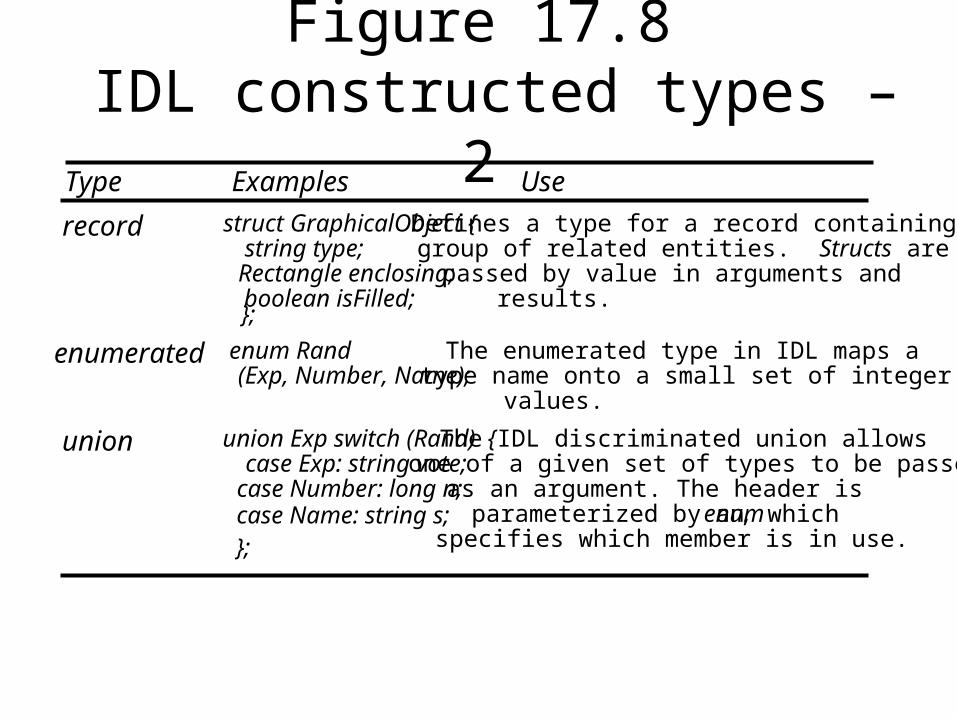
Figure 17.8 IDL constructed types – 2
Type Examples Use
record struct GraphicalObject {
string type; Rectangle enclosing; boolean isFilled;
};
Defines a type for a record containing agroup of related entities. Structs arepassed by value in arguments andresults.
enumerated enum Rand (Exp, Number, Name);
The enumerated type in IDL maps atype name onto a small set of integervalues.
union union Exp switch (Rand) { case Exp: string vote; case Number: long n; case Name: string s;
The IDL discriminated union allowsone of a given set of types to be passedas an argument. The header isparameterized by an enum, which specifies which member is in use. };

Page 684CORBA interoperable object
referencesIOR format
IDL interface type nameProtocol and address details Object key
interface repositoryidentifier
IIOP host domainname
port number adapter name object name

Figure 17.9Naming graph in CORBA
Naming Serviceinitial naming context
ShapeList
CD E
B
initial naming context
P
R S T
V
Q U
initial naming context
XX

Figure 17.10Part of the CORBA Naming
Service NamingContext interface in IDL
struct NameComponent { string id; string kind; };
typedef sequence <NameComponent> Name;
interface NamingContext {void bind (in Name n, in Object obj);
binds the given name and remote object reference in my context.void unbind (in Name n);
removes an existing binding with the given name.void bind_new_context(in Name n);
creates a new naming context and binds it to a given name in my context.Object resolve (in Name n);
looks up the name in my context and returns its remote object reference. void list (in unsigned long how_many, out BindingList bl, out BindingIterator bi);
returns the names in the bindings in my context.};

Figure 17.11CORBA event channels
consumersupplier
proxy consumer
notification
proxy supplier
event channel
notificationnotification
Recommended