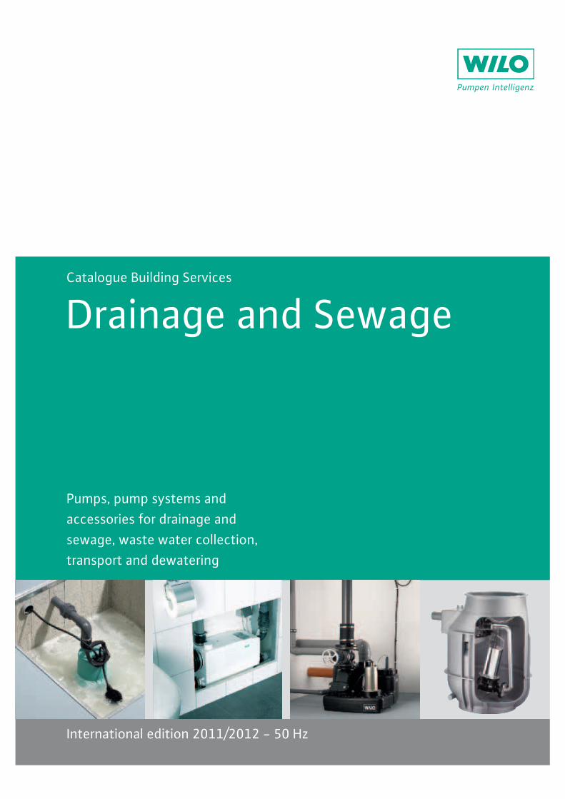
Pumps, pump systems andaccessories for drainage andsewage, waste water collection,transport and dewatering
Catalogue Building Services
Drainage and Sewage
International edition 2011/2012 - 50 Hz

`bhjkqjx{|}x~}��}�j��x�bq�b|}k�b}�k�b��}hj|j��b}qx}q�b}{k�b�}b�b}�}q�b}|x��k��b�}�kj��|}��bk�q��}�{}qb��|}x~}q��b}��k�jq��}q�j|}j|}|qj��}qxx}����}qx�b�k{�b�}���}��k�jq�}k||��k{�b}q�b�b~x�b}�b�jb|}x{}|qkqb�x~�q�b�k�q}�bk|��j{�}�bq�x�|}k{�}b�qb{|jhb}qb|q}��x�b���b|}�b�k�|b}k{}b{���k{�b}qb|q}q�kq}��{|}�x{qj{�k���}~x�}�����}�x��|}�j��}b��x|b}bhb{}q�b}|�k��b|q}x~}�bk�{b||b|�}�}��x���q}��|q}�k||}x��}qb|q|}�jq�}~��j{�}�x�x��|}�b~x�b}jq}j|}k���xhb�}~x�}�j|q�j��qjx{}qx}x��}��|qx�b�|�}<=>?@=>B?CEF=>@HJC=E?>BKH>LCEK?OQHRCJU?K=?J=?VVVWVCR=WX=@YZB
[\?@CX>=@BJ>B]?=F?J=RB>HEXBW?}�x�}q�b}�jx{bb�}x~}�j��}b~~j�jb{��}�|b|}��b�j|jx{}|qk{�k��|}qx}|bq}q�b}�j��b|q}x~}�b{���k��|�}��}�bk{|}x~}��k�jq�}k||��k{�b�
\W\\\\[
3
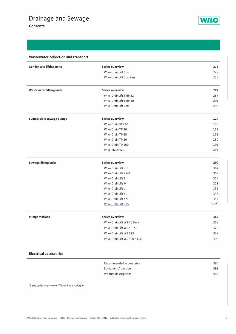
Contents
Wilo Building Services catalogue – 50 Hz – Drainage and sewage – Edition 2011/2012 – Subject to change without prior notice
Dew
ater
ing
Was
tew
ater
col
lect
ion
and
tran
spor
tEl
ectr
ical
acc
esso
ries
Scha
lt- u
nd R
egel
gerä
tePu
mpe
nman
agem
ent
General notes and abbreviations 8
Planning guide 10
Dewatering 30
Submersible drainage pumpsSelf-priming drainage pumpsDrainage pumps for hot waterSubmersible sewage pumps with maceratorSubmersible sewage pumps
Wastewater collection and transport 276
Condensate lifting unitsWastewater lifting unitsSubmersible sewage pumpsSewage lifting unitsPump stations
Electrical accessories 396
Recommended accessoriesEquipment/functionProduct descriptions
4 Wilo Building Services catalogue – 50 Hz – Drainage and sewage – Edition 2011/2012 – Subject to change without prior notice
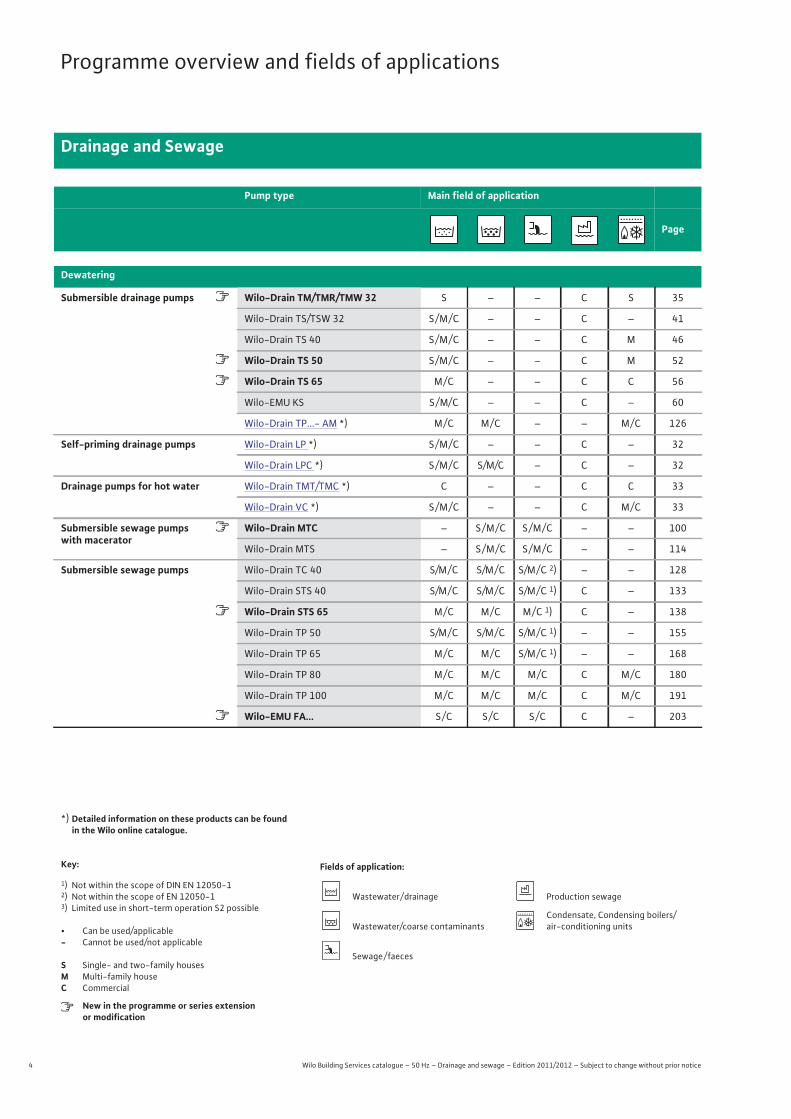
Programme overview and fields of applications
Drainage and Sewage
Pump type Main field of application
Page
Dewatering
Submersible drainage pumps � Wilo-Drain TM/TMR/TMW 32 S – – C S 35
Wilo-Drain TS/TSW 32 S / M / C – – C – 41
Wilo-Drain TS 40 S / M / C – – C M 46
� Wilo-Drain TS 50 S / M / C – – C M 52
� Wilo-Drain TS 65 M / C – – C C 56
Wilo-EMU KS S / M/ C – – C – 60
Wilo-Drain TP...- AM *) M / C M / C – – M / C 126
Self-priming drainage pumps Wilo-Drain LP *) S / M / C – – C – 32
Wilo-Drain LPC *) S / M / C S/M/C – C – 32
Drainage pumps for hot water Wilo-Drain TMT/TMC *) C – – C C 33
Wilo-Drain VC *) S / M / C – – C M / C 33
Submersible sewage pumps �with macerator
Wilo-Drain MTC – S / M / C S / M / C – – 100
Wilo-Drain MTS – S / M / C S / M / C – – 114
Submersible sewage pumps Wilo-Drain TC 40 S/M / C S/M / C S/M / C 2) – – 128
Wilo-Drain STS 40 S/M / C S/M / C S/M / C 1) C – 133
� Wilo-Drain STS 65 M / C M / C M / C 1) C – 138
Wilo-Drain TP 50 S/M / C S/M / C S/M / C 1) – – 155
Wilo-Drain TP 65 M / C M / C S/M / C 1) – – 168
Wilo-Drain TP 80 M / C M / C M / C C M / C 180
Wilo-Drain TP 100 M / C M / C M / C C M / C 191
� Wilo-EMU FA… S / C S / C S / C C – 203
*) Detailed information on these products can be found in the Wilo online catalogue.
Key: Fields of application:
1) Not within the scope of DIN EN 12050-12) Not within the scope of EN 12050-13) Limited use in short-term operation S2 possible
• Can be used/applicable- Cannot be used/not applicable
S Single- and two-family housesM Multi-family houseC Commercial
New in the programme or series extensionor modification
Wastewater / drainage Production sewage
Wastewater/coarse contaminantsCondensate, Condensing boilers/air-conditioning units
Sewage / faeces
5
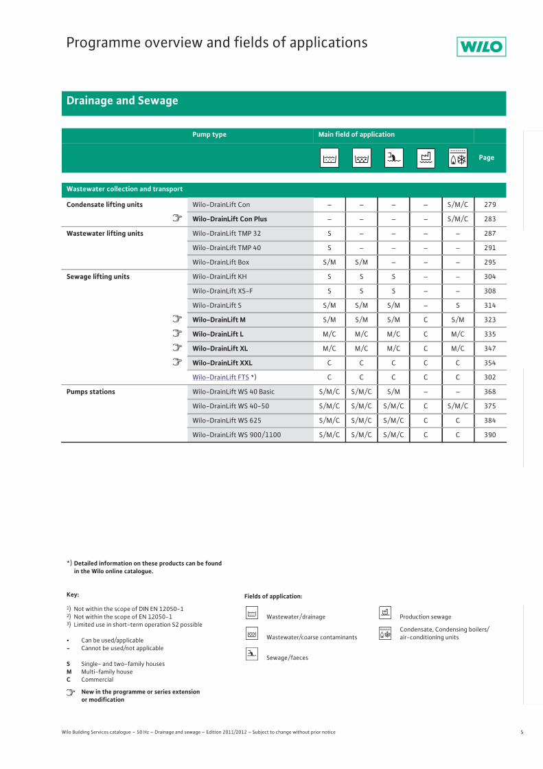
Programme overview and fields of applications
Drainage and Sewage
Wilo Building Services catalogue – 50 Hz – Drainage and sewage – Edition 2011/2012 – Subject to change without prior notice
Dew
ater
ing
Was
tew
ater
col
lect
ion
and
tran
spor
tPr
essu
re d
rain
age
Elec
tric
al a
cces
sorie
sSc
halt-
und
Reg
elge
räte
Pum
penm
anag
emen
t
Wastewater collection and transport
Condensate lifting units Wilo-DrainLift Con – – – – S / M / C 279
� Wilo-DrainLift Con Plus – – – – S / M / C 283
Wastewater lifting units Wilo-DrainLift TMP 32 S – – – – 287
Wilo-DrainLift TMP 40 S – – – – 291
Wilo-DrainLift Box S / M S / M – – – 295
Sewage lifting units Wilo-DrainLift KH S S S – – 304
Wilo-DrainLift XS-F S S S – – 308
Wilo-DrainLift S S / M S / M S / M – S 314
� Wilo-DrainLift M S / M S / M S / M C S / M 323
� Wilo-DrainLift L M / C M / C M / C C M / C 335
� Wilo-DrainLift XL M / C M / C M / C C M / C 347
� Wilo-DrainLift XXL C C C C C 354
Wilo-DrainLift FTS *) C C C C C 302
Pumps stations Wilo-DrainLift WS 40 Basic S / M / C S / M / C S / M – – 368
Wilo-DrainLift WS 40-50 S / M / C S / M / C S / M / C C S / M / C 375
Wilo-DrainLift WS 625 S / M / C S / M / C S / M / C C C 384
Wilo-DrainLift WS 900 / 1100 S / M / C S / M / C S / M / C C C 390
*) Detailed information on these products can be found in the Wilo online catalogue.
Key: Fields of application:
1) Not within the scope of DIN EN 12050-12) Not within the scope of EN 12050-13) Limited use in short-term operation S2 possible
• Can be used/applicable- Cannot be used/not applicable
S Single- and two-family housesM Multi-family houseC Commercial
New in the programme or series extensionor modification
Wastewater / drainage Production sewage
Wastewater/coarse contaminantsCondensate, Condensing boilers/air-conditioning units
Sewage / faeces
Pump type Main field of application
Page
6 Wilo Building Services catalogue – 50 Hz – Drainage and sewage – Edition 2011/2012 – Subject to change without prior notice
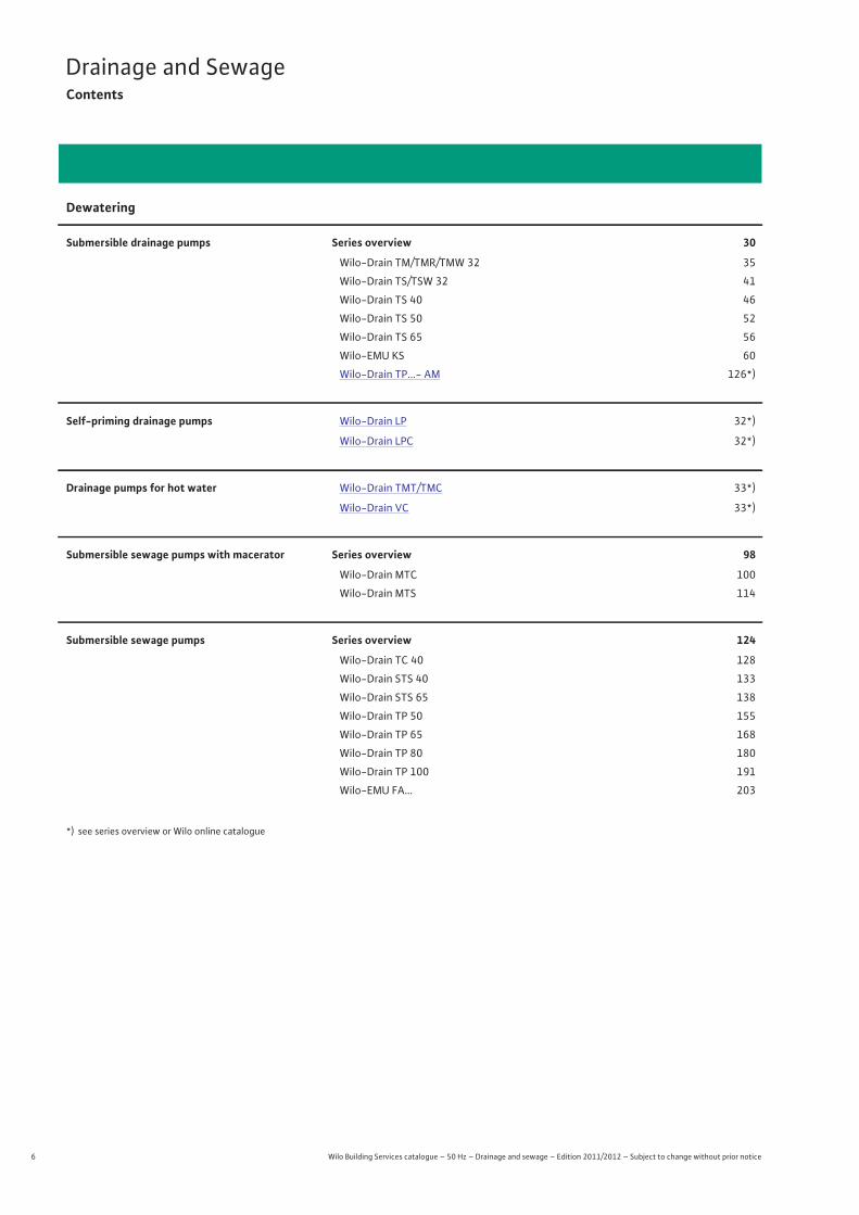
Drainage and SewageContents
Dewatering
Submersible drainage pumps Series overview 30
Wilo-Drain TM/TMR/TMW 32 35
Wilo-Drain TS/TSW 32 41
Wilo-Drain TS 40 46
Wilo-Drain TS 50 52
Wilo-Drain TS 65 56
Wilo-EMU KS 60
Wilo-Drain TP...- AM 126*)
Self-priming drainage pumps Wilo-Drain LP 32*)
Wilo-Drain LPC 32*)
Drainage pumps for hot water Wilo-Drain TMT/TMC 33*)
Wilo-Drain VC 33*)
Submersible sewage pumps with macerator Series overview 98
Wilo-Drain MTC 100
Wilo-Drain MTS 114
Submersible sewage pumps Series overview 124
Wilo-Drain TC 40 128
Wilo-Drain STS 40 133
Wilo-Drain STS 65 138
Wilo-Drain TP 50 155
Wilo-Drain TP 65 168
Wilo-Drain TP 80 180
Wilo-Drain TP 100 191
Wilo-EMU FA… 203
*) see series overview or Wilo online catalogue
7
Drainage and SewageContents
Wilo Building Services catalogue – 50 Hz – Drainage and sewage – Edition 2011/2012 – Subject to change without prior notice
Dew
ater
ing
Was
tew
ater
col
lect
ion
and
tran
spor
tPr
essu
re d
rain
age
Elec
tric
al a
cces
sorie
sSc
halt-
und
Reg
elge
räte
Pum
penm
anag
emen
t
Wastewater collection and transport
Condensate lifting units Series overview 276
Wilo-DrainLift Con 279
Wilo-DrainLift Con Plus 283
Wastewater lifting units Series overview 277
Wilo-DrainLift TMP 32 287
Wilo-DrainLift TMP 40 291
Wilo-DrainLift Box 295
Submersible sewage pumps Series overview 124
Wilo-Drain STS 65 138
Wilo-Drain TP 50 155
Wilo-Drain TP 65 168
Wilo-Drain TP 80 180
Wilo-Drain TP 100 191
Wilo-EMU FA… 203
Sewage lifting units Series overview 299
Wilo-DrainLift KH 304
Wilo-DrainLift XS-F 308
Wilo-DrainLift S 314
Wilo-DrainLift M 323
Wilo-DrainLift L 335
Wilo-DrainLift XL 347
Wilo-DrainLift XXL 354
Wilo-DrainLift FTS 302*)
Pumps stations Series overview 365
Wilo-DrainLift WS 40 Basic 368
Wilo-DrainLift WS 40-50 375
Wilo-DrainLift WS 625 384
Wilo-DrainLift WS 900 / 1100 390
Electrical accessories
Recommended accessories 396
Equipment/function 399
Product descriptions 402
*) see series overview or Wilo online catalogue
8 Wilo Building Services catalogue – 50 Hz – Drainage and sewage – Edition 2011/2012 – Subject to change without prior notice
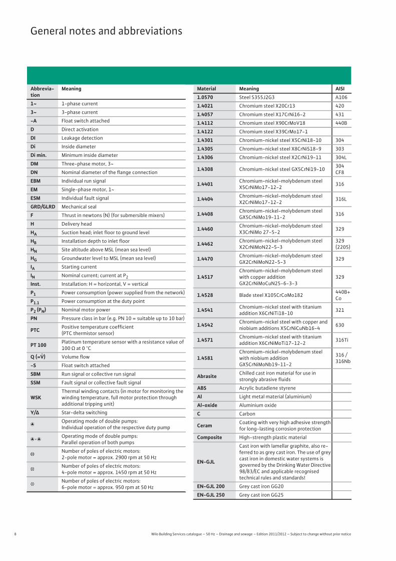
General notes and abbreviations
Abbrevia-tion
Meaning
1~ 1-phase current
3~ 3-phase current
-A Float switch attached
D Direct activation
DI Leakage detection
Di Inside diameter
Di min. Minimum inside diameter
DM Three-phase motor, 3~
DN Nominal diameter of the flange connection
EBM Individual run signal
EM Single-phase motor, 1~
ESM Individual fault signal
GRD/GLRD Mechanical seal
F Thrust in newtons (N) (for submersible mixers)
H Delivery head
HA Suction head; inlet floor to ground level
HB Installation depth to inlet floor
HN Site altitude above MSL (mean sea level)
HG Groundwater level to MSL (mean sea level)
IA Starting current
IN Nominal current; current at P2Inst. Installation: H = horizontal, V = vertical
P1 Power consumption (power supplied from the network)
P1.1 Power consumption at the duty point
P2 (PN) Nominal motor power
PN Pressure class in bar (e.g. PN 10 = suitable up to 10 bar)
PTC Positive temperature coefficient(PTC thermistor sensor)
PT 100 Platinum temperature sensor with a resistance value of 100 ¾ at 0 °C
Q (=�) Volume flow
-S Float switch attached
SBM Run signal or collective run signal
SSM Fault signal or collective fault signal
WSKThermal winding contacts (in motor for monitoring the winding temperature, full motor protection through additional tripping unit)
Y/� Star-delta switching
�Operating mode of double pumps:Individual operation of the respective duty pump
�Operating mode of double pumps:Parallel operation of both pumps
�Number of poles of electric motors: 2-pole motor = approx. 2900 rpm at 50 Hz
�Number of poles of electric motors: 4-pole motor = approx. 1450 rpm at 50 Hz
�Number of poles of electric motors: 6-pole motor = approx. 950 rpm at 50 Hz
Material Meaning AISI1.0570 Steel S355J2G3 A106
1.4021 Chromium steel X20Cr13 420
1.4057 Chromium steel X17CrNi16-2 431
1.4112 Chromium steel X90CrMoV18 440B
1.4122 Chromium steel X39CrMo17-1
1.4301 Chromium-nickel steel X5CrNi18-10 304
1.4305 Chromium-nickel steel X8CrNiS18-9 303
1.4306 Chromium-nickel steel X2CrNi19-11 304L
1.4308 Chromium-nickel steel GX5CrNi19-10 304 CF8
1.4401 Chromium-nickel-molybdenum steel X5CrNiMo17-12-2 316
1.4404 Chromium-nickel-molybdenum steel X2CrNiMo17-12-2 316L
1.4408 Chromium-nickel-molybdenum steel GX5CrNiMo19-11-2 316
1.4460 Chromium-nickel-molybdenum steel X3CrNiMo 27-5-2 329
1.4462 Chromium-nickel-molybdenum steel X2CrNiMoN22-5-3
329 (2205)
1.4470 Chromium-nickel-molybdenum steel GX2CrNiMoN22-5-3 329
1.4517Chromium-nickel-molybdenum steel with copper additionGX2CrNiMoCuN25-6-3-3
329
1.4528 Blade steel X105CrCoMo182 440B+Co
1.4541 Chromium-nickel steel with titanium addition X6CrNiTi18-10 321
1.4542 Chromium-nickel steel with copper and niobium additions X5CrNiCuNb16-4 630
1.4571 Chromium-nickel steel with titanium addition X6CrNiMoTi17-12-2 316Ti
1.4581Chromium-nickel-molybdenum steel with niobium additionGX5CrNiMoNb19-11-2
316 / 316Nb
Abrasite Chilled cast iron material for use in strongly abrasive fluids
ABS Acrylic butadiene styrene
Al Light metal material (aluminium)
Al-oxide Aluminium oxide
C Carbon
Ceram Coating with very high adhesive strength for long-lasting corrosion protection
Composite High-strength plastic material
EN-GJL
Cast iron with lamellar graphite, also re-ferred to as grey cast iron. The use of grey cast iron in domestic water systems is governed by the Drinking Water Directive 98/83/EC and applicable recognised technical rules and standards!
EN-GJL 200 Grey cast iron GG20
EN-GJL 250 Grey cast iron GG25
9
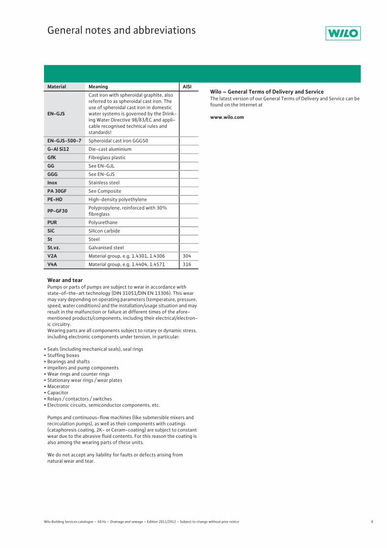
General notes and abbreviations
Wilo Building Services catalogue – 50 Hz – Drainage and sewage – Edition 2011/2012 – Subject to change without prior notice
Wear and tearPumps or parts of pumps are subject to wear in accordance with state-of-the-art technology (DIN 31051/DIN EN 13306). This wear may vary depending on operating parameters (temperature, pressure, speed, water conditions) and the installation/usage situation and may result in the malfunction or failure at different times of the afore-mentioned products/components, including their electrical/electron-ic circuitry.Wearing parts are all components subject to rotary or dynamic stress, including electronic components under tension, in particular:
• Seals (including mechanical seals), seal rings• Stuffing boxes • Bearings and shafts• Impellers and pump components• Wear rings and counter rings• Stationary wear rings / wear plates• Macerator • Capacitor• Relays / contactors / switches• Electronic circuits, semiconductor components, etc.
Pumps and continuous-flow machines (like submersible mixers and recirculation pumps), as well as their components with coatings (cataphoresis coating, 2K- or Ceram-coating) are subject to constant wear due to the abrasive fluid contents. For this reason the coating is also among the wearing parts of these units.
We do not accept any liability for faults or defects arising from natural wear and tear.
Wilo – General Terms of Delivery and ServiceThe latest version of our General Terms of Delivery and Service can be found on the Internet at
www.wilo.comEN-GJS
Cast iron with spheroidal graphite, also referred to as spheroidal cast iron. The use of spheroidal cast iron in domestic water systems is governed by the Drink-ing Water Directive 98/83/EC and appli-cable recognised technical rules and standards!
EN-GJS-500-7 Spheroidal cast iron GGG50
G-Al Si12 Die-cast aluminium
GfK Fibreglass plastic
GG See EN-GJL
GGG See EN-GJS
Inox Stainless steel
PA 30GF See Composite
PE-HD High-density polyethylene
PP-GF30 Polypropylene, reinforced with 30% fibreglass
PUR Polyurethane
SiC Silicon carbide
St Steel
St.vz. Galvanised steel
V2A Material group, e.g. 1.4301, 1.4306 304
V4A Material group, e.g. 1.4404, 1.4571 316
Material Meaning AISI
10 Wilo Building Services catalogue – 50 Hz – Drainage and sewage – Edition 2011/2012 – Subject to change without prior notice
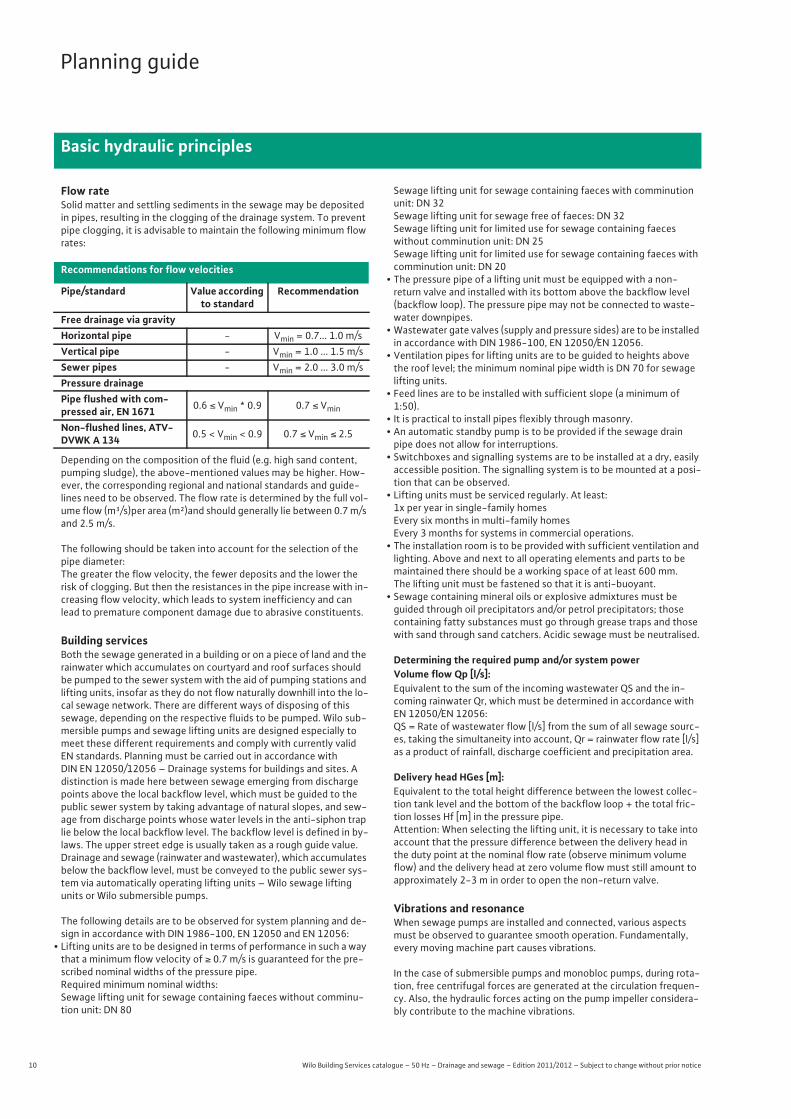
Planning guide
Basic hydraulic principles
Flow rateSolid matter and settling sediments in the sewage may be deposited in pipes, resulting in the clogging of the drainage system. To prevent pipe clogging, it is advisable to maintain the following minimum flow rates:
Depending on the composition of the fluid (e.g. high sand content, pumping sludge), the above-mentioned values may be higher. How-ever, the corresponding regional and national standards and guide-lines need to be observed. The flow rate is determined by the full vol-ume flow (m³/s)per area (m²)and should generally lie between 0.7 m/s and 2.5 m/s.
The following should be taken into account for the selection of the pipe diameter:The greater the flow velocity, the fewer deposits and the lower the risk of clogging. But then the resistances in the pipe increase with in-creasing flow velocity, which leads to system inefficiency and can lead to premature component damage due to abrasive constituents.
Building services Both the sewage generated in a building or on a piece of land and the rainwater which accumulates on courtyard and roof surfaces should be pumped to the sewer system with the aid of pumping stations and lifting units, insofar as they do not flow naturally downhill into the lo-cal sewage network. There are different ways of disposing of this sewage, depending on the respective fluids to be pumped. Wilo sub-mersible pumps and sewage lifting units are designed especially to meet these different requirements and comply with currently valid EN standards. Planning must be carried out in accordance with DIN EN 12050/12056 – Drainage systems for buildings and sites. A distinction is made here between sewage emerging from discharge points above the local backflow level, which must be guided to the public sewer system by taking advantage of natural slopes, and sew-age from discharge points whose water levels in the anti-siphon trap lie below the local backflow level. The backflow level is defined in by-laws. The upper street edge is usually taken as a rough guide value. Drainage and sewage (rainwater and wastewater), which accumulates below the backflow level, must be conveyed to the public sewer sys-tem via automatically operating lifting units – Wilo sewage lifting units or Wilo submersible pumps.
The following details are to be observed for system planning and de-sign in accordance with DIN 1986-100, EN 12050 and EN 12056:
• Lifting units are to be designed in terms of performance in such a way that a minimum flow velocity of Ç 0.7 m/s is guaranteed for the pre-scribed nominal widths of the pressure pipe.Required minimum nominal widths:Sewage lifting unit for sewage containing faeces without comminu-tion unit: DN 80
Sewage lifting unit for sewage containing faeces with comminution unit: DN 32Sewage lifting unit for sewage free of faeces: DN 32Sewage lifting unit for limited use for sewage containing faeces without comminution unit: DN 25Sewage lifting unit for limited use for sewage containing faeces with comminution unit: DN 20
• The pressure pipe of a lifting unit must be equipped with a non-return valve and installed with its bottom above the backflow level (backflow loop). The pressure pipe may not be connected to waste-water downpipes.
• Wastewater gate valves (supply and pressure sides) are to be installed in accordance with DIN 1986-100, EN 12050/EN 12056.
• Ventilation pipes for lifting units are to be guided to heights above the roof level; the minimum nominal pipe width is DN 70 for sewage lifting units.
• Feed lines are to be installed with sufficient slope (a minimum of 1:50).
• It is practical to install pipes flexibly through masonry.• An automatic standby pump is to be provided if the sewage drain pipe does not allow for interruptions.
• Switchboxes and signalling systems are to be installed at a dry, easily accessible position. The signalling system is to be mounted at a posi-tion that can be observed.
• Lifting units must be serviced regularly. At least:1x per year in single-family homesEvery six months in multi-family homesEvery 3 months for systems in commercial operations.
• The installation room is to be provided with sufficient ventilation and lighting. Above and next to all operating elements and parts to be maintained there should be a working space of at least 600 mm.The lifting unit must be fastened so that it is anti-buoyant.
• Sewage containing mineral oils or explosive admixtures must be guided through oil precipitators and/or petrol precipitators; those containing fatty substances must go through grease traps and those with sand through sand catchers. Acidic sewage must be neutralised.
Determining the required pump and/or system powerVolume flow Qp [l/s]:Equivalent to the sum of the incoming wastewater QS and the in-coming rainwater Qr, which must be determined in accordance with EN 12050/EN 12056: QS = Rate of wastewater flow [l/s] from the sum of all sewage sourc-es, taking the simultaneity into account, Qr = rainwater flow rate [l/s] as a product of rainfall, discharge coefficient and precipitation area.
Delivery head HGes [m]:Equivalent to the total height difference between the lowest collec-tion tank level and the bottom of the backflow loop + the total fric-tion losses Hf [m] in the pressure pipe.Attention: When selecting the lifting unit, it is necessary to take into account that the pressure difference between the delivery head in the duty point at the nominal flow rate (observe minimum volume flow) and the delivery head at zero volume flow must still amount to approximately 2-3 m in order to open the non-return valve.
Vibrations and resonanceWhen sewage pumps are installed and connected, various aspects must be observed to guarantee smooth operation. Fundamentally, every moving machine part causes vibrations.
In the case of submersible pumps and monobloc pumps, during rota-tion, free centrifugal forces are generated at the circulation frequen-cy. Also, the hydraulic forces acting on the pump impeller considera-bly contribute to the machine vibrations.
Recommendations for flow velocities
Pipe/standard Value according to standard
Recommendation
Free drainage via gravityHorizontal pipe - Vmin = 0.7... 1.0 m/sVertical pipe - Vmin = 1.0 ... 1.5 m/sSewer pipes - Vmin = 2.0 ... 3.0 m/sPressure drainagePipe flushed with com-pressed air, EN 1671 0.6 Ë Vmin * 0.9 0.7 Ë Vmin
Non-flushed lines, ATV-DVWK A 134 0.5 < Vmin < 0.9 0.7 Ë Vmin Ë 2.5
11
Planning guide
Basic hydraulic principles
Wilo Building Services catalogue – 50 Hz – Drainage and sewage – Edition 2011/2012 – Subject to change without prior notice
In order to avoid malfunctions and damage, the strength of the vibra-tions in the operating state may not exceed a certain threshold. This is achieved by statically and dynamically balancing the corresponding parts.
If the pumps are subject to additional external vibrations due to un-favourable installation and connections, these vibrations are super-imposed. These vibrations can put high levels of stress on individual components.
In order for the pumps to work without disturbances and to have long service lives, they must be installed according to the generally valid rules of technology.
General notes• The volume flow to be handled by the pump must exceed the volume flow of approaching sewage. Make sure that the pumps run as close to the optimum duty point as possible to ensure durability and opti-mum performance.
• Consider a loss in performance with increasing pump age. The volume flow and pressures can be negatively influenced by abrasion and cor-rosion.
• Design the pump so that it operates as efficiently as possible. • Steep pump curves prevent clogging in the pressure pipe, since when there's increased backpressure, the pump also increases pressure along its pump curve and rinses away the deposits.
• When selecting accessories, take the material properties into consid-eration with regard to the corrosion- and abrasion-resistance.
• Compensate for peak inflows for economical and safety reasons by using double-pump systems (pump splitting, standby pump is always to be considered separately).
• If the transfer point (drainage pipe) lies underneath the sump level, ventilation should be provided, since otherwise the created suction could empty the complete sump, incl. the pump. This would result in ventilation difficulties and should therefore be checked in advance.
• Observe the various operating conditions for pipes which are not per-manently installed in one place. The partial and full-filling situations should be observed.
Pipe and pump material When designing, observe that the following influences could mean additional requirements for your system:
• Flow velocity of the fluid > Noises, wear • pH value of the fluid > Material damage, corrosion • Chemical constituents of the fluid > Corrosion• Atmospheric conditions, such as humidity, salt content in the air, etc.
> Corrosion• Outside and fluid temperature > Fluid aggressiveness, corrosion• Dwell time of the fluid in the pipe > Odour development • Leakage currents due to using materials having different electron
negativity
Due to the material changes and the resulting pressure level change, pipes for underground use should be designed as PN 10 pipes.
12 Wilo Building Services catalogue – 50 Hz – Drainage and sewage – Edition 2011/2012 – Subject to change without prior notice
Planning guide
Pressure losses
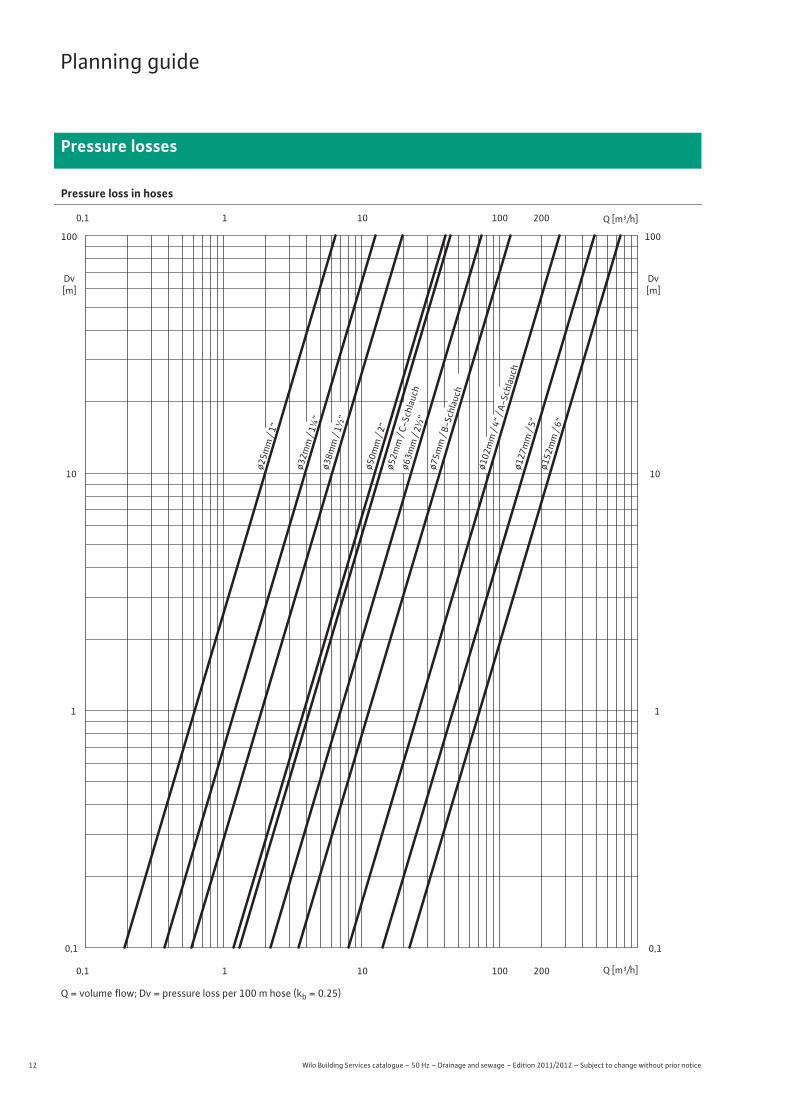
Pressure loss in hoses
Q = volume flow; Dv = pressure loss per 100 m hose (kb = 0.25)
ø25m
m /
1“
ø32m
m /
1¼“
ø38m
m /
1½“
ø63m
m / 2½
“
ø50m
m / 2“
ø127
mm
/ 5“
ø152
mm
/ 6“
ø52m
m /
C-Sc
hlau
ch
ø75m
m / B-
Schlau
ch
ø102
mm
/ 4“
/ A-
Schlau
ch
1
10
100
0,1
0,1
10 100 2001 Q [m³/h]
Q [m³/h]0,1 10 1001 200
Dv[m]
Dv[m]
1
10
100
0,1
13
Planning guide
Pressure losses
Wilo Building Services catalogue – 50 Hz – Drainage and sewage – Edition 2011/2012 – Subject to change without prior notice
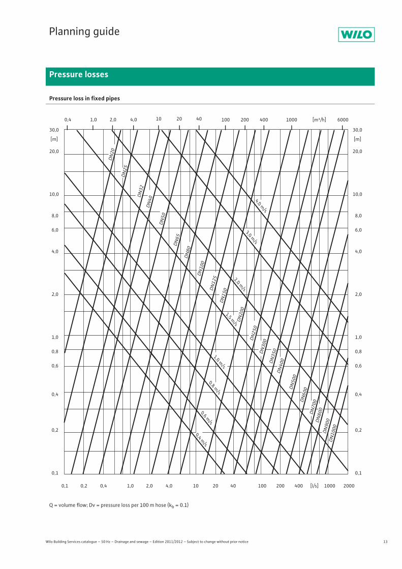
Pressure loss in fixed pipes
Q = volume flow; Dv = pressure loss per 100 m hose (kb = 0.1)
30,0
[m] [m]
20,0
10,0
8,0
6,0
4,0
2,0
1,0
0,8
0,6
0,4
0,2
0,1
30,0
20,0
10,0
8,0
6,0
4,0
2,0
1,0
0,8
0,6
0,4
0,2
0,1
0,1 10 20 400,2 1,0 2,0 4,0 100 200 400 [l/s] 1000 2000
0,4 1,0 2,0 4,0 10 20 40 100 200 400 1000 [m³/h] 6000
DN
40
DN50
DN
65
DN20
DN25
DN
32
DN
80
DN
100
DN
125
DN
150
DN20
0
DN25
0D
N30
0D
N35
0D
N40
0
DN50
0D
N60
0D
N70
0D
N80
0D
N90
0D
N10
00
0,4 m/s
0,6 m/s
0,8 m/s
1,5 m/s
1,0 m/s
2,0 m/s
3,0 m/s
4,0 m/s
0,4
14 Wilo Building Services catalogue – 50 Hz – Drainage and sewage – Edition 2011/2012 – Subject to change without prior notice
Planning guide
Pressure losses
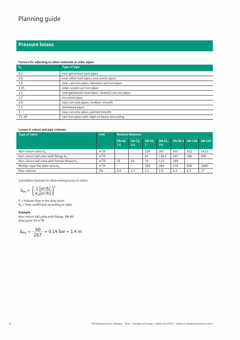
Calculation formula for determining losses in valves
Ò = Volume flow in the duty pointKV = flow coefficient according to table
ExampleNon-return ball valve with flange, DN 80,duty point 40 m3/h
Factors for adjusting to other materials or older pipes:kb Type of pipe
0.1 new galvanised steel pipes0.8 new rolled steel pipes, new plastic pipes 1.0 new cast iron pipes, bitumen cast iron pipes1.25 older rusted cast iron pipes1.5 new galvanised steel pipes, cleaned cast iron pipes,1.7 incrusted pipes2.0 new concrete pipes, medium-smooth2.5 stoneware pipes3 new concrete pipes, painted smooth15-30 cast iron pipes with slight to heavy encrusting
Losses in valves and pipe volumesType of valve Unit Nominal diameter
DN 40, 1¼
DN 32, 1½
DN 50,2
DN 65, 2½
DN 80,3 DN 100 DN 150
Non-return valve KV m3/h - - 158 267 405 632 1423Non-return ball valve with flange KV m3/h - - 87 136.5 267 396 890Non-return ball valve with female thread KV m3/h 26 54 70 115 180 - -Wedge-type flat slide valve KV m3/h - - 160 280 470 830 2000Pipe volumes l/m 0.8 1.3 2.1 2.9 4.3 8.2 17
( )ΔPV = [m³/h] ²KV[m³/h]
ΔPV = = 0.14 bar = 1.4 m 40267
15
Planning guide
Installation types
Wilo Building Services catalogue – 50 Hz – Drainage and sewage – Edition 2011/2012 – Subject to change without prior notice
Very different types of installations are used in submersible systems in municipal applications. The type of installation depends mainly on the application purpose and the investment volume.
Basically, three main installation types are distinguished:• Wet well installation, stationary• Wet well installation, portable• Dry well installation, stationary
The pipe sump installations are also required. The type of installation depends mainly on the requirements of the planning engineer and the operator. Different viewpoints arise, which each are justified in terms of the individual field of application.
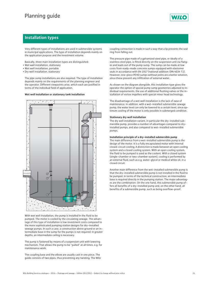
Wet well installation or stationary tank installation
With wet well installation, the pump is installed in the fluid to be pumped. The motor is cooled by the circulating sewage. The advan-tage of this type of installation is low investment costs compared to the more sophisticated pumping station designs for dry-installed sewage pumps. In such a case, a construction above ground or an in-termediate base in the sump for the pumps is not required. In greater depths, an intermediate ceiling is necessary.
The pump is fastened by means of a suspension unit with lowering mechanism. That allows the pump to be “pulled” at all times, e.g. for maintenance work.
The coupling base and the elbow are usually cast in one piece. The guide consists of two pipes, thus preventing any twisting. The Wilo
coupling connection is made in such a way that a lip prevents the seal ring from falling out.
The pressure pipe made of a galvanized steel pipe, or ideally of a stainless steel pipe, is fitted directly on the suspension unit via flang-es and leads out of the pump sump. The sump can be made at low costs from ready-made concrete sumps equipped with elastomer seals in accordance with EN 1917 (national addition: DIN 4034 T1). However, one-piece PEHD sumps without joints are a better solution, since these prevent any infiltration of external water.
As shown on the diagram alongside, this installation type gives the operator the option of special pump sump geometries adjusted to in-dividual requirements, the use of additional flushing valves or the in-stallation of vortex impellers with special mixer head technology.
The disadvantage of a wet well installation is the lack of ease of maintenance. In addition, with a wet-installed submersible sewage pump, the water level can only be lowered to a certain level, since op-timum cooling of the motor is only possible in submerged condition.
Stationary dry well installationThe dry well installation variant, in particular the dry-installed sub-mersible pump, provides a number of advantages compared to dry-installed pumps, and also compared to wet-installed submersible pumps.
Installation principle of a dry-installed submersible pumpThe main difference from a wet-installed submersible pump is the design of the motor. It is a fully encapsulated motor with internal closed-circuit cooling. A distinction is made between an open cooling system and a closed cooling system. With an open cooling system, the fluid to be pumped is used as the coolant. With a closed system (single-chamber or two-chamber system), cooling is performed by an external fluid, such as e.g. water-glycol or medical white oil, in a closed circuit.
Another main difference from the wet-installed submersible pump is that the dry-installed submersible pump is not installed in the fluid to be pumped. In terms of the technical construction, an intermediate base is required directly in the pumping station. The major advantag-es are the combination. On the one hand, this submersible pump of-fers all benefits of a dry-installed pump and, on the other hand, all benefits of a submersible pump, such as being overflow-proof.
16 Wilo Building Services catalogue – 50 Hz – Drainage and sewage – Edition 2011/2012 – Subject to change without prior notice
Planning guide
Installation types
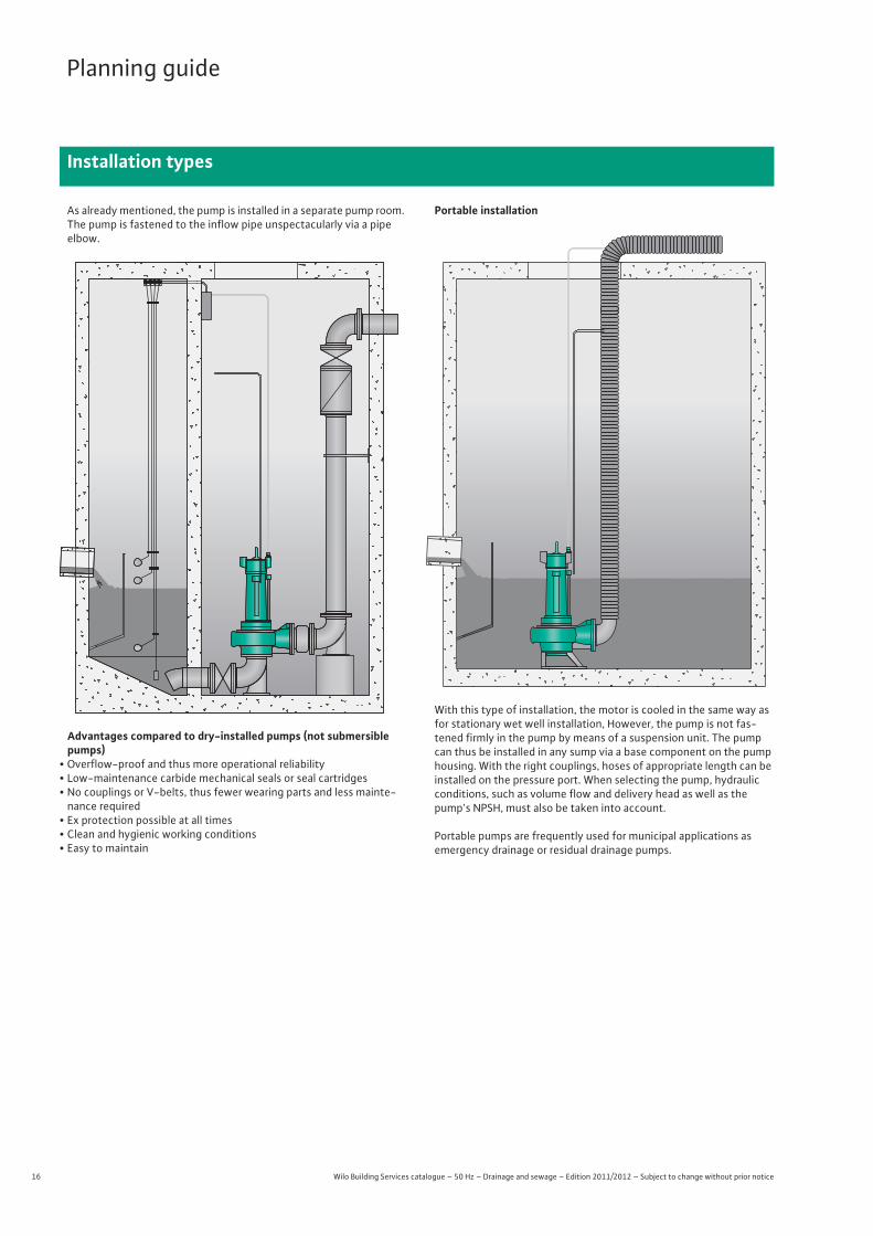
As already mentioned, the pump is installed in a separate pump room. The pump is fastened to the inflow pipe unspectacularly via a pipeelbow.
Advantages compared to dry-installed pumps (not submersible pumps)
• Overflow-proof and thus more operational reliability • Low-maintenance carbide mechanical seals or seal cartridges • No couplings or V-belts, thus fewer wearing parts and less mainte-
nance required • Ex protection possible at all times • Clean and hygienic working conditions • Easy to maintain
Portable installation
With this type of installation, the motor is cooled in the same way as for stationary wet well installation, However, the pump is not fas-tened firmly in the pump by means of a suspension unit. The pump can thus be installed in any sump via a base component on the pump housing. With the right couplings, hoses of appropriate length can be installed on the pressure port. When selecting the pump, hydraulic conditions, such as volume flow and delivery head as well as the pump's NPSH, must also be taken into account.
Portable pumps are frequently used for municipal applications as emergency drainage or residual drainage pumps.
17
Planning guide
Pumped fluids and impeller shapes
Wilo Building Services catalogue – 50 Hz – Drainage and sewage – Edition 2011/2012 – Subject to change without prior notice
Pumped fluid (untreated sewage, sludge)Solids concentrationNon-clog impellers and vortex impellers are suitable for fluids with a DM content (dry matter) of max. 8% (rough guideline).
The prerequisite for perfect pumping in all cases is that the pump's fluid still flows on its own.
ViscosityThe pump curve and the given motor power values in the type sheets apply to the pumping of water = 1.0 x 10⁻⁶ m2/sec. The diagram for friction losses also applies to water only. If the viscosity of the fluid is greater than v = 1.5 x 10⁻⁶ m2/sec., the following aspects need to be observed in particular:
• Increased friction losses in the pipe (when determining the delivery head)
• Increased power requirement of the pump (when determining the drive power)
Specific weightThe motor power values given in the type sheets apply to water as the fluid (= 1 kg/dm3). With a higher specific weight of the fluid than that of water, an increased power requirement of the pump needs to be taken into account.
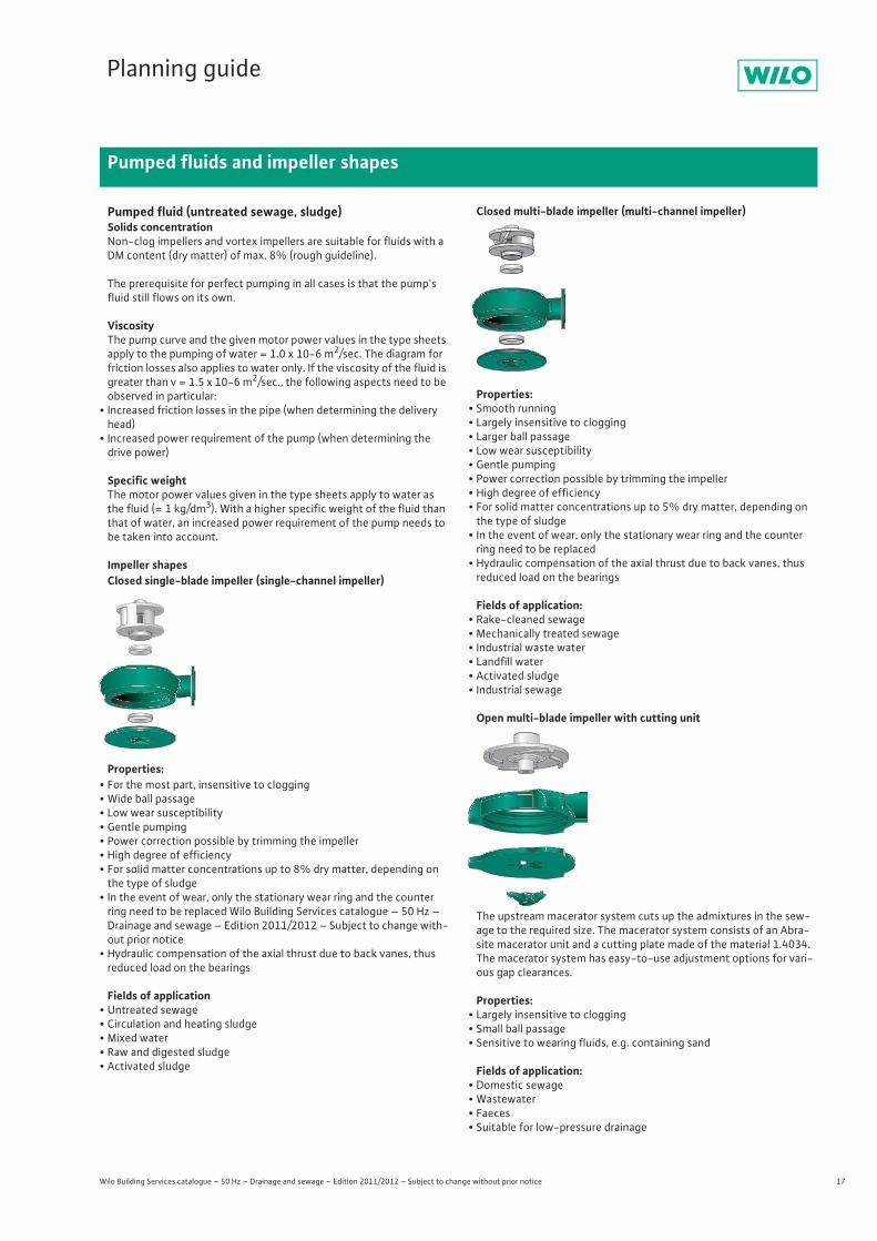
Impeller shapes Closed single-blade impeller (single-channel impeller)
Properties:• For the most part, insensitive to clogging• Wide ball passage• Low wear susceptibility• Gentle pumping• Power correction possible by trimming the impeller• High degree of efficiency• For solid matter concentrations up to 8% dry matter, depending on the type of sludge
• In the event of wear, only the stationary wear ring and the counter ring need to be replaced Wilo Building Services catalogue – 50 Hz – Drainage and sewage – Edition 2011/2012 – Subject to change with-out prior notice
• Hydraulic compensation of the axial thrust due to back vanes, thus reduced load on the bearings
Fields of application• Untreated sewage• Circulation and heating sludge• Mixed water• Raw and digested sludge• Activated sludge
Closed multi-blade impeller (multi-channel impeller)
Properties:• Smooth running• Largely insensitive to clogging• Larger ball passage• Low wear susceptibility• Gentle pumping• Power correction possible by trimming the impeller• High degree of efficiency• For solid matter concentrations up to 5% dry matter, depending on the type of sludge
• In the event of wear, only the stationary wear ring and the counter ring need to be replaced
• Hydraulic compensation of the axial thrust due to back vanes, thus reduced load on the bearings
Fields of application:• Rake-cleaned sewage • Mechanically treated sewage• Industrial waste water• Landfill water • Activated sludge• Industrial sewage
Open multi-blade impeller with cutting unit
The upstream macerator system cuts up the admixtures in the sew-age to the required size. The macerator system consists of an Abra-site macerator unit and a cutting plate made of the material 1.4034. The macerator system has easy-to-use adjustment options for vari-ous gap clearances.
Properties:• Largely insensitive to clogging• Small ball passage • Sensitive to wearing fluids, e.g. containing sand
Fields of application:• Domestic sewage• Wastewater• Faeces• Suitable for low-pressure drainage
18 Wilo Building Services catalogue – 50 Hz – Drainage and sewage – Edition 2011/2012 – Subject to change without prior notice
Planning guide
Pumped fluids and impeller shapes
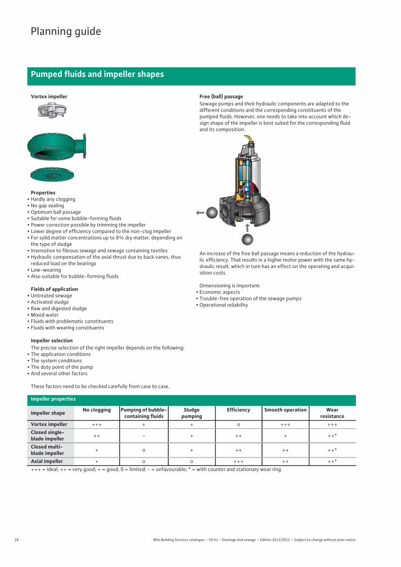
Vortex impeller
Properties• Hardly any clogging • No gap sealing • Optimum ball passage • Suitable for some bubble-forming fluids• Power correction possible by trimming the impeller• Lower degree of efficiency compared to the non-clog impeller• For solid matter concentrations up to 8% dry matter, depending on the type of sludge
• Insensitive to fibrous sewage and sewage containing textiles • Hydraulic compensation of the axial thrust due to back vanes, thus
reduced load on the bearings• Low-wearing• Also suitable for bubble-forming fluids
Fields of application• Untreated sewage• Activated sludge• Raw and digested sludge• Mixed water• Fluids with problematic constituents• Fluids with wearing constituents
Impeller selectionThe precise selection of the right impeller depends on the following:
• The application conditions • The system conditions • The duty point of the pump • And several other factors
These factors need to be checked carefully from case to case.
Free (ball) passageSewage pumps and their hydraulic components are adapted to the different conditions and the corresponding constituents of the pumped fluids. However, one needs to take into account which de-sign shape of the impeller is best suited for the corresponding fluid and its composition.
An increase of the free ball passage means a reduction of the hydrau-lic efficiency. That results in a higher motor power with the same hy-draulic result, which in turn has an effect on the operating and acqui-sition costs.
Dimensioning is important:• Economic aspects• Trouble-free operation of the sewage pumps• Operational reliability
Impeller properties
Impeller shape No clogging Pumping of bubble-containing fluids
Sludge pumping
Efficiency Smooth operation Wearresistance
Vortex impeller +++ + + o +++ +++Closed single-blade impeller ++ - + ++ + ++*
Closed multi-blade impeller + o + ++ ++ ++*
Axial impeller + o o +++ ++ ++*+++ = ideal; ++ = very good; + = good; 0 = limited; - = unfavourable; * = with counter and stationary wear ring
19
Planning guide
Basic electric principles
Wilo Building Services catalogue – 50 Hz – Drainage and sewage – Edition 2011/2012 – Subject to change without prior notice
Starting currentThis is the current which is required during the start-up operation of a machine to overcome friction losses and starting torques. The starting current can be up to seven times that of the nominal current, depending on the type of start-up. When there is instability in the electric mains or for larger motors, corresponding devices must be provided to reduce the starting current. These could be soft starters, frequency converters, etc. Designing the motor as a star-delta motor can already reduce the starting current.
ATEXSee “Ex protection” chapter
Operating modes (in acc. with DIN EN 60034-1)See “Operating modes” chapter
Individual run signalIndicates the fault of the individual pump and demonstrates an exact evaluation method for building control systems.
Explosion protectionExplosion protection has been modified in the EU. Since July 1, 2003, the European directive 94/9/EC has applied for explosion protection. The modifications generally have to do with the fact that the entire unit (not only the electrical part) has to be tested and certified taking explosion-protection aspects into account. A definition concerning the zones in which explosion protection is to be provided is the re-sponsibility of the operator. The units identified by Wilo as explo-sion-protected are designed for Zone 1, Group II, Category 2, i.e. for a high degree of safety and for the cast that potentially explosive at-mospheres can be expected.
Furthermore, a few series are also approved according to the Ameri-can FM directive.
For further information, see the “Ex protection” chapter.
Ex-rated cut-off relayUsing ex-rated cut-off relays, float switches can also be used in po-tentially explosive environments (Zone 1 for fluids containing fae-ces). These relays reduce the flowing current to a magnitude which doesn't cause sparks, even in the event of an error, which would cause the fluid or its surroundings to ignite.
FMSee “Ex protection” chapter
Motor protectionFor a safe operation of a motor, this must be protected against unac-ceptable high warming. Such an unacceptable warming can result from faults which increase the motor current and strongly heat up the motor:
• Overload• Phase failure• Undervoltage• Blocking
These faults can be recognised by an overload relay or a motor pro-tection switch which then switch off the motor. Overload relays and motor protection switches may only be set to the maximum nominal current of the motor.
Overload relayPrinciple of operation:The thermal protection is ensured by bimetals which heat up as the motor current flows via heating windings. For every conductive line to the motor, a separate bimetal with corresponding heating winding is provided. If the power consumption of just one motor winding ex-ceeds the predefined value over several seconds, the generated heat will deform the bimetal which then triggers the latch and switches off the motor contactor. Also, if a phase fails (irregular heating of the bi-metal strips), the motor is switched off after a short period of time. After a thermal triggering has taken place, the switch can only be switched on again after the bimetals have cooled down sufficiently. Overload relays don't switch off the motor directly, they have a con-tact for relatively low switching frequencies. This contact activates a contactor which then switches the motor off in the event of a fault. In contrast to the motor protection switch, an overload relay does not have a short-circuit trip. This is why safety fuses should be installed in the supply line for one or several motors which are protected by overload relays. Moreover, the reactivation of overload relays can be done manually or automatically. The reactivation should be done manually in order to avoid a permanent switching on and off when there is a fault.
Motor protection switchWith motor protection switches, motors can be switched on and off under normal operating conditions. The thermal triggering is based on the principle of the overload relay. However, the operator is in a position to switch off the motor during operation or in the event of fault. Moreover, most motor protection switches have an additional magnetic quick triggering which protects the downstream line and the motor against short circuits. With lower currents, these switches are short-circuit proof, i.e. a back-up fuse may not be required.
Other faults which lead up to an increased heating-up:• Dry-running of motors that may only operate in a submerged state• Unacceptable high fluid temperatures / ambient temperature• Unacceptable running times in short-term operation
These faults do not influence the current consumption of the motor and can therefore not be recognised by the upstream overload pro-tection! For such faults, temperature sensors are used which are di-rectly imbedded in the component to be protected (motor winding).
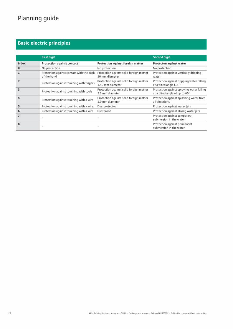
Protection measures (DIN VDE 0100-410)Protection classes: (DIN EN 50529 / VDE 0470 Part 1)The type of protection which a housing offers to e.g. protect against direct contact, is defined by the IP (International Protection) codes. This is made up of the “IP” and two digits (e.g. IP 54).
First digit:• Protection of people against contact with dangerous parts• Protection of the equipment against ingress of solid foreign matter
Second digit:• Protection of the equipment against the ingress of water
20 Wilo Building Services catalogue – 50 Hz – Drainage and sewage – Edition 2011/2012 – Subject to change without prior notice
Planning guide
Basic electric principles
First digit Second digit
Index Protection against contact Protection against foreign matter Protecton against water0 No protection No protection No protection1 Protection against contact with the back
of the handProtection against solid foreign matter 50 mm diameter
Protection against vertically dripping water
2 Protection against touching with fingers Protection against solid foreign matter 12.5 mm diameter
Protection against dripping water falling at a tilted angle (15°)
3 Protection against touching with tools Protection against solid foreign matter 2.5 mm diameter
Protection against spraying water falling at a tilted angle of up to 60°
4 Protection against touching with a wire Protection against solid foreign matter 1.0 mm diameter
Protection against splashing water from all directions
5 Protection against touching with a wire Dustprotected Protection against water jets6 Protection against touching with a wire Dustproof Protection against strong water jets7 - - Protection against temporary
submersion in the water8 - - Protection against permanent
submersion in the water
21
Planning guide
Operating modes
Wilo Building Services catalogue – 50 Hz – Drainage and sewage – Edition 2011/2012 – Subject to change without prior notice
The operating mode defines the permissible motor activation period. Fundamentally, it is to be made sure that the installed temperature monitor of the motors is correctly connected. This ensures that the temperature classes of the windings are complied with if the operat-ing time is exceeded or incorrect operating mode is used.
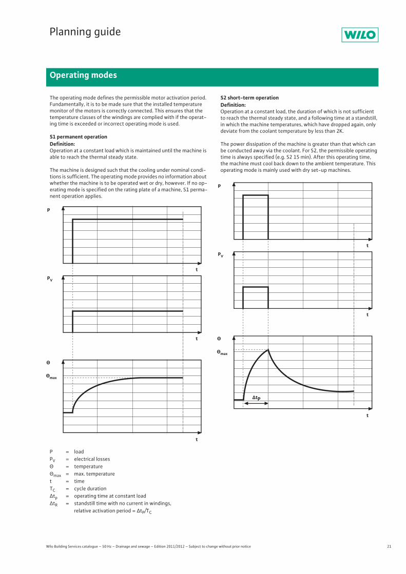
S1 permanent operationDefinition:Operation at a constant load which is maintained until the machine is able to reach the thermal steady state.
The machine is designed such that the cooling under nominal condi-tions is sufficient. The operating mode provides no information about whether the machine is to be operated wet or dry, however. If no op-erating mode is specified on the rating plate of a machine, S1 perma-nent operation applies.
S2 short-term operationDefinition:Operation at a constant load, the duration of which is not sufficient to reach the thermal steady state, and a following time at a standstill, in which the machine temperatures, which have dropped again, only deviate from the coolant temperature by less than 2K.
The power dissipation of the machine is greater than that which can be conducted away via the coolant. For S2, the permissible operating time is always specified (e.g. S2 15 min). After this operating time, the machine must cool back down to the ambient temperature. This operating mode is mainly used with dry set-up machines.
P = loadPV = electrical losses× = temperature×max = max. temperaturet = timeTC = cycle durationØtp = operating time at constant loadØtR = standstill time with no current in windings,
relative activation period = ØtP/TC
P
t
t
t
PV
Θ
Θmax
P
t
t
t
PV
Θ
ΔtP
Θmax
22 Wilo Building Services catalogue – 50 Hz – Drainage and sewage – Edition 2011/2012 – Subject to change without prior notice
Planning guide
Operating modes
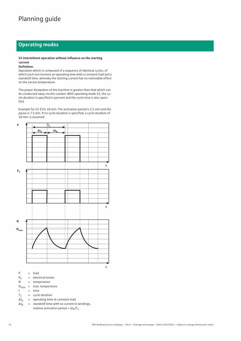
S3 intermittent operation without influence on the startingcurrentDefinition:Operation which is composed of a sequence of identical cycles, of which each one involves an operating time with a constant load and a standstill time, whereby the starting current has no noticeable effect on the excess temperature.
The power dissipation of the machine is greater than that which can be conducted away via the coolant. With operating mode S3, the cy-cle duration is specified in percent and the cycle time is also speci-fied.
Example for S3 25% 10 min: The activation period is 2.5 min and the pause is 7.5 min. If no cycle duration is specified, a cycle duration of 10 min. is assumed.
P = loadPV = electrical losses× = temperature×max = max. temperaturet = timeTC = cycle durationØtp = operating time at constant loadØtR = standstill time with no current in windings,
relative activation period = ØtP/TC
P
t
t
t
PV
Θ
ΔtP ΔtR
TC
Θmax
23
Planning guide
Level measuring systems
Wilo Building Services catalogue – 50 Hz – Drainage and sewage – Edition 2011/2012 – Subject to change without prior notice
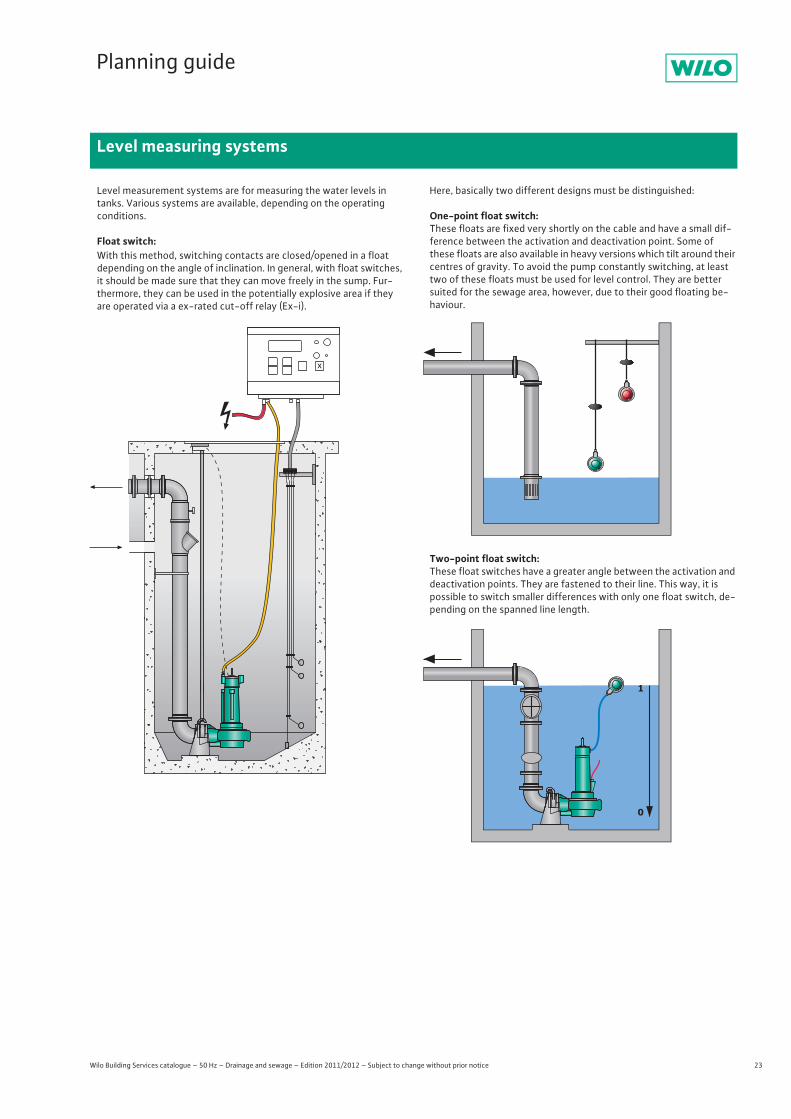
Level measurement systems are for measuring the water levels in tanks. Various systems are available, depending on the operating conditions.
Float switch:With this method, switching contacts are closed/opened in a float depending on the angle of inclination. In general, with float switches, it should be made sure that they can move freely in the sump. Fur-thermore, they can be used in the potentially explosive area if they are operated via a ex-rated cut-off relay (Ex-i).
Here, basically two different designs must be distinguished:
One-point float switch:These floats are fixed very shortly on the cable and have a small dif-ference between the activation and deactivation point. Some of these floats are also available in heavy versions which tilt around their centres of gravity. To avoid the pump constantly switching, at least two of these floats must be used for level control. They are better suited for the sewage area, however, due to their good floating be-haviour.
Two-point float switch:These float switches have a greater angle between the activation and deactivation points. They are fastened to their line. This way, it is possible to switch smaller differences with only one float switch, de-pending on the spanned line length.
1
0
24 Wilo Building Services catalogue – 50 Hz – Drainage and sewage – Edition 2011/2012 – Subject to change without prior notice
Planning guide
Level measuring systems
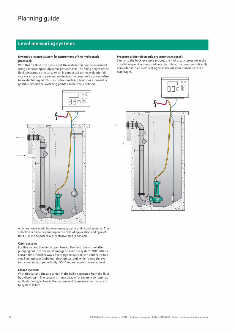
Dynamic pressure system (measurement of the hydrostaticpressure):With this method, the pressure at the installation point is measured using a measuring bell/dynamic pressure bell. The filling height of the fluid generates a pressure, which is conducted to the evaluation de-vice via a hose. In the evaluation device, the pressure is converted in-to an electric signal. Thus, a continuous filling level measurement is possible, where the switching points can be freely defined.
A distinction is made between open systems and closed systems. The selection is made depending on the field of application and type of fluid. Use in the potentially explosive area is possible.
Open system:For this variant, the bell is open toward the fluid. Every time after pumping out, the bell must emerge to vent the system. “Off” after a certain time. Another way of venting the system is to connect it to a small compressor (bubbling-through system), which vents the sys-tem constantly or periodically. “Off” depending on the water level.
Closed system:With this variant, the air cushion in the bell is separated from the fluid by a diaphragm. The system is then suitable for severely contaminat-ed fluids. Leaks/air loss in the system lead to measurement errors or to system failure.
Pressure probe (electronic pressure transducer):Similar to the back-pressure probes, the hydrostatic pressure at the installation point is measured here, too. Here, the pressure is directly converted into an electrical signal in the pressure transducer via adiaphragm.
25
Planning guide
Level measuring systems
Wilo Building Services catalogue – 50 Hz – Drainage and sewage – Edition 2011/2012 – Subject to change without prior notice
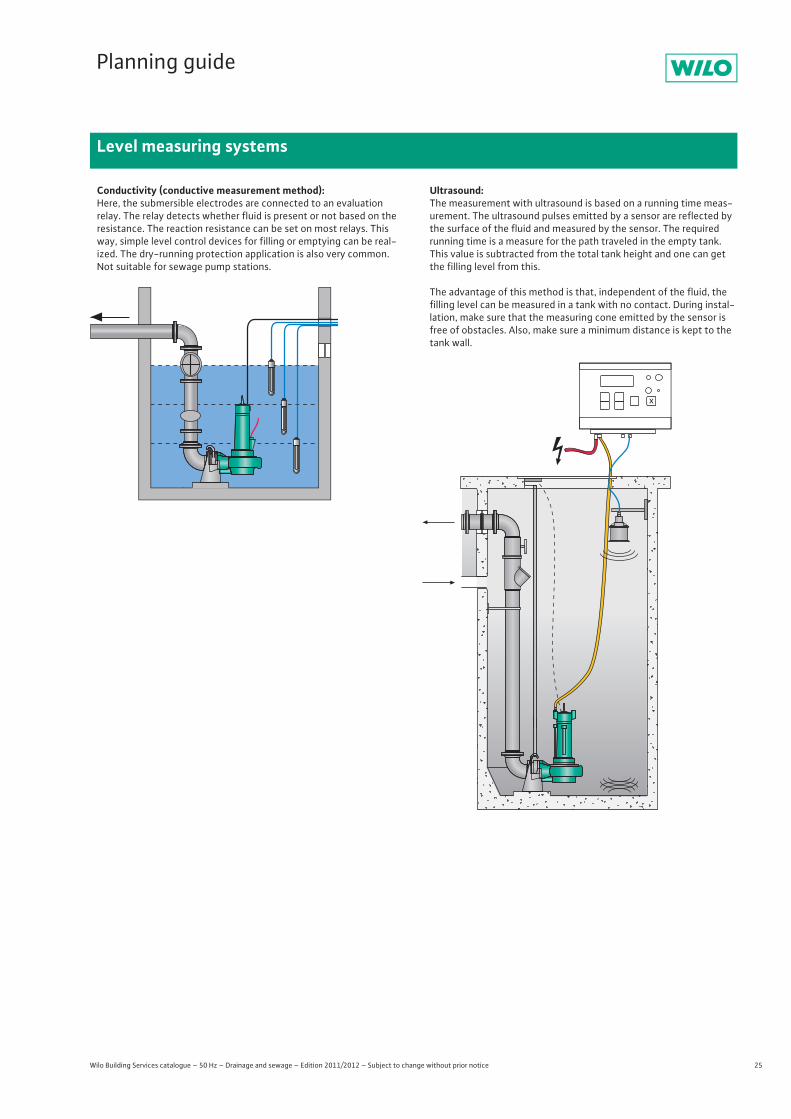
Conductivity (conductive measurement method):Here, the submersible electrodes are connected to an evaluationrelay. The relay detects whether fluid is present or not based on the resistance. The reaction resistance can be set on most relays. This way, simple level control devices for filling or emptying can be real-ized. The dry-running protection application is also very common. Not suitable for sewage pump stations.
Ultrasound:The measurement with ultrasound is based on a running time meas-urement. The ultrasound pulses emitted by a sensor are reflected by the surface of the fluid and measured by the sensor. The required running time is a measure for the path traveled in the empty tank. This value is subtracted from the total tank height and one can get the filling level from this.
The advantage of this method is that, independent of the fluid, the filling level can be measured in a tank with no contact. During instal-lation, make sure that the measuring cone emitted by the sensor is free of obstacles. Also, make sure a minimum distance is kept to the tank wall.
26 Wilo Building Services catalogue – 50 Hz – Drainage and sewage – Edition 2011/2012 – Subject to change without prior notice
Planning guide
Explosion protection
Wilo units are approved for use in potentially explosive environments. For this, they are certified in accordance with various standards.
• The European ATEX standard• The American FM standard
ATEX standard The units are designed according to “EC directive 94/ 09/EC” (ATEX 95) and the European standards DIN EN 60079-0 and EN 60079-1. They may be operated in potentially explosive environments which require electrical devices of device group II, category 2.
Therefore, they may be used in zone 1 and zone 2. These units may not be used in zone 0.
The Wilo units are designated as follows: II 2 G Ex d IIB T4
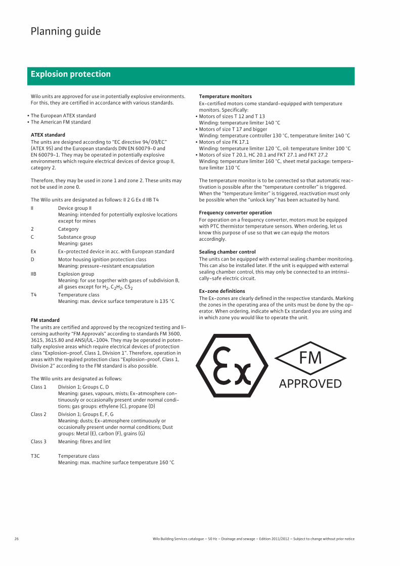
FM standardThe units are certified and approved by the recognized testing and li-censing authority “FM Approvals” according to standards FM 3600, 3615, 3615.80 and ANSI/UL-1004. They may be operated in poten-tially explosive areas which require electrical devices of protection class “Explosion-proof, Class 1, Division 1”. Therefore, operation in areas with the required protection class “Explosion-proof, Class 1, Division 2” according to the FM standard is also possible.
The Wilo units are designated as follows:
Temperature monitorsEx-certified motors come standard-equipped with temperature monitors. Specifically:
• Motors of sizes T 12 and T 13Winding: temperature limiter 140 °C
• Motors of size T 17 and biggerWinding: temperature controller 130 °C, temperature limiter 140 °C
• Motors of size FK 17.1Winding: temperature limiter 120 °C, oil: temperature limiter 100 °C
• Motors of size T 20.1, HC 20.1 and FKT 27.1 and FKT 27.2Winding: temperature limiter 160 °C, sheet metal package: tempera-ture limiter 110 °C
The temperature monitor is to be connected so that automatic reac-tivation is possible after the “temperature controller” is triggered. When the “temperature limiter” is triggered, reactivation must only be possible when the “unlock key” has been actuated by hand.
Frequency converter operationFor operation on a frequency converter, motors must be equipped with PTC thermistor temperature sensors. When ordering, let us know this purpose of use so that we can equip the motorsaccordingly.
Sealing chamber control The units can be equipped with external sealing chamber monitoring. This can also be installed later. If the unit is equipped with external sealing chamber control, this may only be connected to an intrinsi-cally-safe electric circuit.
Ex-zone definitionsThe Ex-zones are clearly defined in the respective standards. Marking the zones in the operating area of the units must be done by the op-erator. When ordering, indicate which Ex standard you are using and in which zone you would like to operate the unit.
II Device group IIMeaning: intended for potentially explosive locations except for mines
2 CategoryC Substance group
Meaning: gasesEx Ex-protected device in acc. with European standardD Motor housing ignition protection class
Meaning: pressure-resistant encapsulationIIB Explosion group
Meaning: for use together with gases of subdivision B, all gases except for H2, C2H2, CS2
T4 Temperature classMeaning: max. device surface temperature is 135 °C
Class 1 Division 1; Groups C, DMeaning: gases, vapours, mists; Ex-atmosphere con-tinuously or occasionally present under normal condi-tions; gas groups: ethylene (C), propane (D)
Class 2 Division 1; Groups E, F, GMeaning: dusts; Ex-atmosphere continuously oroccasionally present under normal conditions; Dust groups: Metal (E), carbon (F), grains (G)
Class 3 Meaning: fibres and lint
T3C Temperature classMeaning: max. machine surface temperature 160 °C
FMAPPROVED
27
Planning guide
Materials
Wilo Building Services catalogue – 50 Hz – Drainage and sewage – Edition 2011/2012 – Subject to change without prior notice
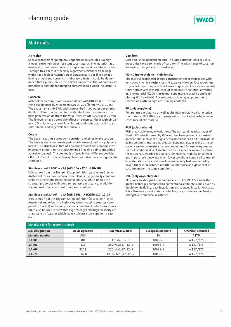
AbrasiteSpecial materials for pump housings and impellers. This is a high-alloyed, extremely wear-resistant cast material. The material has a martensitic basic structure with a high chrome-alloy carbide content. Through this, there is especially high wear-resistance to sewage which has a high concentration of abrasive particles (like sewage having a high sand content). In laboratory tests, it could be deter-mined that a pump service life 7 times longer than that of normal cast materials is possible for pumping abrasive media when “Abrasite” is used.
Concrete Material for creating sumps in accordance with DIN 4034-1. The con-crete quality used by Wilo meets DIN EN 206 (formerly DIN 1045). The exact name is B45WU with a prescribed max. water penetration depth of 30 mm, according to the standard. From experience, the max. penetration depth of the Wilo DrainLift WB is even just 20 mm. The following have a corrosive effect on concrete: Fluids with pH val-ue < 6.5, sulphuric, hydrochloric, butyric and lactic acids, sulphates, salts, animal and vegetable fats and oils.
CeramThe Ceram coating is a modern corrosion and abrasion protection. The basis is aluminium oxide parts which are enclosed in a polymere matrix. The structure is that of a diamond model and combines two important properties: no predetermined breaking points and a high adhesive strength. The coating is offered in four different qualities: C0, C1, C2 and C3. For certain applications individual coatings can be combined.
Stainless steel 1.4301 - V2A (AISI 304 - X5CrNi18-10)V2A comes from the Thyssen Krupp definition (test series 2, type Austenite) for a chrome-nickel steel. This is the generally common stainless steel standard in the pump industry, which unifies the strength properties with good temperature resistance. In addition, the material is very resistant to organic solutions.
Stainless steel 1.4404 - V4A (AISI 316L - X2CrNiMo17-12-3)V4A comes from the Thyssen Krupp definition (test series 4, type Austenite) and refers to a high-alloyed non-rusting steel (as com-pared to 1.4301) with a molybdenum constituent, which can some-times also be used in seawater. High strength and high elasticity are characteristic features which make stainless steel superior to cast iron.
Cast ironCast iron is the standard material in pump construction. For years, most units have been made of cast iron. The advantages of cast iron are mainly their price and robustness.
PE-HD (polyethylene - high density)The most used material in pipe construction for sewage pipes with very good chemical resistance and extremely low surface roughness to prevent depositing and flow losses. High impact resistance and ul-timate strain with low influence of temperature are other advantag-es. The material PE100 is used more and more in practice and is re-placing PE80 and GGG. Advantages, such as laying pipes during renovations, offer a high cost-savings potential.
PP (polypropylene)Temperature resistance as well as chemical resistance characterize this material. DIN 8078 is extremely robust thanks to the high impact resistance of the material.
PUR (polyurethane)PUR is available in many variations. The outstanding advantages of Baydur GS, which is used by Wilo and has been proven in industrial applications, such as the high chemical resistance to diluted acids, al-kaline solutions, motor oils, greases, benzines, etc. as well as the cor-rosion- and micro-resistance, are predestined for use in aggressive fluids. In addition, it is characterized by its superior wear-resistance, rot resistance, weather resistance, dimensional stability under heat and impact resistance at a much lower weight as compared to metal-lic materials, such as cast iron. In a sand-slurry test conducted by Bayer, the wear resistance or PUR is about twice as high as that of cast iron under the same conditions.
PVC (polyvinyl-chloride)PE sumps are designed in accordance with DIN 19537-1 and offer great advantages compared to conventional concrete sumps, such as durability, flexibility, easy installation and reduced installation costs. It is a flame-resistant material, which equally combines mechanical strength and chemical resistance.
Material table for austenitic steels
DIN designation US designation Chemical symbol European standard American standard Material number AISI EN ASTM1.4301 304 X5CrNi18-10 10088-3 A 167 /2761.4401 316 X5CrNiMo17-12-2 10088-3 A 167 /2761.4404 316 L X2CrNiMo17-12-3 10088-3 A 167 /2761.4571 316 Ti X6CrNiMoTi17-12-2 10088-3 A 167 /276
28 Wilo Building Services catalogue – 50 Hz – Drainage and sewage – Edition 2011/2012 – Subject to change without prior notice
Planning guide
Pumps stations
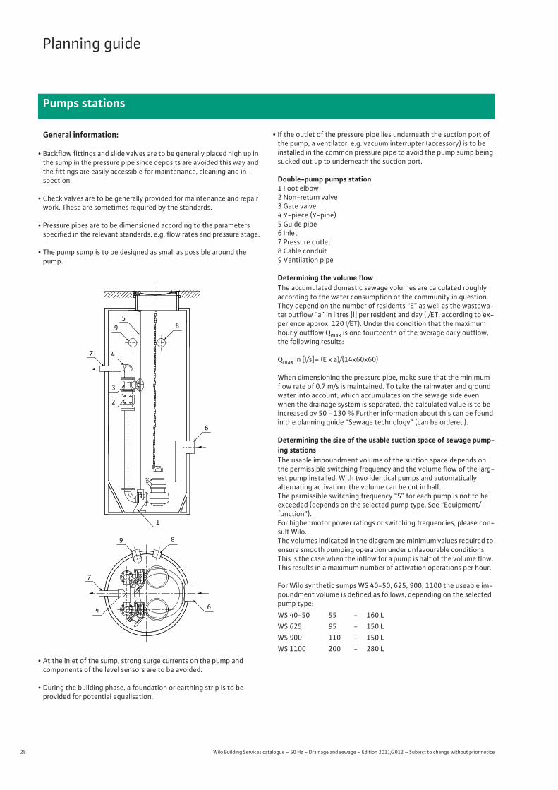
General information:
• Backflow fittings and slide valves are to be generally placed high up in the sump in the pressure pipe since deposits are avoided this way and the fittings are easily accessible for maintenance, cleaning and in-spection.
• Check valves are to be generally provided for maintenance and repair work. These are sometimes required by the standards.
• Pressure pipes are to be dimensioned according to the parameters specified in the relevant standards, e.g. flow rates and pressure stage.
• The pump sump is to be designed as small as possible around the pump.
• At the inlet of the sump, strong surge currents on the pump and components of the level sensors are to be avoided.
• During the building phase, a foundation or earthing strip is to beprovided for potential equalisation.
• If the outlet of the pressure pipe lies underneath the suction port of the pump, a ventilator, e.g. vacuum interrupter (accessory) is to be installed in the common pressure pipe to avoid the pump sump being sucked out up to underneath the suction port.
Double-pump pumps station 1 Foot elbow2 Non-return valve3 Gate valve4 Y-piece (Y-pipe)5 Guide pipe6 Inlet7 Pressure outlet8 Cable conduit9 Ventilation pipe
Determining the volume flowThe accumulated domestic sewage volumes are calculated roughly according to the water consumption of the community in question. They depend on the number of residents “E” as well as the wastewa-ter outflow “a” in litres [l] per resident and day (l/ET, according to ex-perience approx. 120 l/ET). Under the condition that the maximum hourly outflow Qmax is one fourteenth of the average daily outflow, the following results:
Qmax in [l/s]= (E x a)/(14x60x60)
When dimensioning the pressure pipe, make sure that the minimum flow rate of 0.7 m/s is maintained. To take the rainwater and ground water into account, which accumulates on the sewage side even when the drainage system is separated, the calculated value is to be increased by 50 - 130 % Further information about this can be found in the planning guide “Sewage technology” (can be ordered).
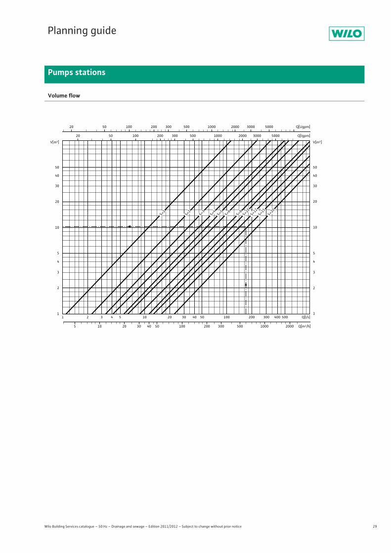
Determining the size of the usable suction space of sewage pump-ing stationsThe usable impoundment volume of the suction space depends on the permissible switching frequency and the volume flow of the larg-est pump installed. With two identical pumps and automaticallyalternating activation, the volume can be cut in half.The permissible switching frequency “S” for each pump is not to be exceeded (depends on the selected pump type. See “Equipment/function”).For higher motor power ratings or switching frequencies, please con-sult Wilo.The volumes indicated in the diagram are minimum values required to ensure smooth pumping operation under unfavourable conditions. This is the case when the inflow for a pump is half of the volume flow. This results in a maximum number of activation operations per hour.
For Wilo synthetic sumps WS 40-50, 625, 900, 1100 the useable im-poundment volume is defined as follows, depending on the selected pump type:
95
8
6
7 4
3
2
1
6
7
4
89
WS 40-50 55 - 160 LWS 625 95 - 150 LWS 900 110 - 150 LWS 1100 200 - 280 L
29
Planning guide
Pumps stations
Wilo Building Services catalogue – 50 Hz – Drainage and sewage – Edition 2011/2012 – Subject to change without prior notice
Volume flow
40
30
4
3
V[m³]
50
20
10
5
2
1
40
30
4
3
20 50 100 200 300 500 1000 2000 3000 5000 Q[Igpm]
20 50 100 200 300 500 1000 2000 3000 5000 Q[Ugpm]
1 2 3 4 5 10 20 30 40 50 100 200 300 400 500 Q[l/s]
V[m³]
50
20
10
5
2
1
5 10 20 30 40 50 100 200 300 500 1000 2000 Q[m³/h]
S=1
S=2
S=3
S=4
S=5
S=6
S=8
S=10
S=12
S=15
S=20
30 Wilo Building Services catalogue – 50 Hz – Drainage and sewage – Edition 2011/2012 – Subject to change without prior notice
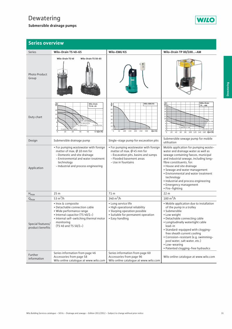
DewateringSubmersible drainage pumps
Series overview
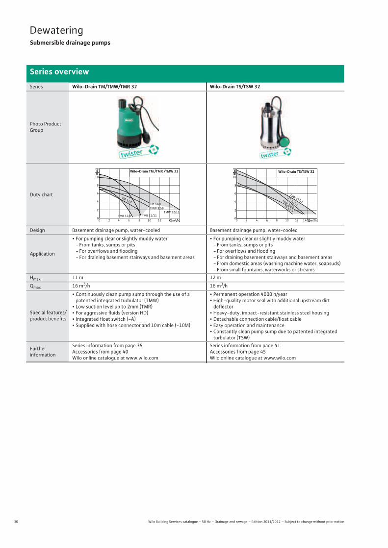
Series Wilo-Drain TM/TMW/TMR 32 Wilo-Drain TS/TSW 32
Photo Product Group
Duty chart
Design Basement drainage pump, water-cooled Basement drainage pump, water-cooled
Application
• For pumping clear or slightly muddy water- From tanks, sumps or pits- For overflows and flooding- For draining basement stairways and basement areas
• For pumping clear or slightly muddy water- From tanks, sumps or pits- For overflows and flooding- For draining basement stairways and basement areas- From domestic areas (washing machine water, soapsuds)- From small fountains, waterworks or streams
Hmax 11 m 12 m
Qmax 16 m3/h 16 m3/h
Special features/product benefits
• Continuously clean pump sump through the use of apatented integrated turbulator (TMW)
• Low suction level up to 2mm (TMR)• For aggressive fluids (version HD)• Integrated float switch (-A)• Supplied with hose connector and 10m cable (-10M)
• Permanent operation 4000 h/year • High-quality motor seal with additional upstream dirt
deflector• Heavy-duty, impact-resistant stainless steel housing • Detachable connection cable/float cable• Easy operation and maintenance• Constantly clean pump sump due to patented integrated turbulator (TSW)
Furtherinformation
Series information from page 35Accessories from page 40Wilo online catalogue at www.wilo.com
Series information from page 41Accessories from page 45Wilo online catalogue at www.wilo.com
Wilo-Drain TM /TMR /TMW 32
TMW 32/11
TM 32/8TMW 32/8
TMR 32/110
2
4
6
8
10
H[m]
0 2 4 6 8 10 12 Q[m³/h]
TM 32/7
TMR 32/8
H[m]
Q[m³/h]
Wilo-Drain TS/TSW 32
0 2 4 6
10
8
6
4
2
08 10 12 14
TS 32/12
TSW 32/11TSW 32/8TS 32/9
31
DewateringSubmersible drainage pumps
Wilo Building Services catalogue – 50 Hz – Drainage and sewage – Edition 2011/2012 – Subject to change without prior notice
Series overview
Dew
ater
ing
Series Wilo-Drain TS 40-65 Wilo-EMU KS Wilo-Drain TP 80/100...-AM
Photo Product Group
Duty chart
Design Submersible drainage pump Single-stage pump for excavation pits Submersible sewage pump for mobile utilisation
Application
• For pumping wastewater with foreign matter of max. Ø 10 mm for-Domestic and site drainage- Environmental and water treatment technology
- Industrial and process engineering
• For pumping wastewater with foreign matter of max. Ø 45 mm for- Excavation pits, basins and sumps- Flooded basement areas- Use in fountains
Mobile application for pumping waste-water and drainage water as well as sewage containing faeces, municipal and industrial sewage, including long-fibre constituents, for:• House and site drainage• Sewage and water management• Environmental and water treatment technology
• Industrial and process engineering• Emergency management• Fire-fighting
Hmax 25 m 71 m 22 m
Qmax 53 m3/h 340 m3/h 180 m3/h
Special features/product benefits
• Inox & composite• Detachable connection cable• Wide performance range• Internal capacitor (TS 40/1~)• Internal self-switching thermal motor
monitoring(TS 40 and TS 50/1~)
• Long service life• High operational reliability• Slurping operation possible• Suitable for permanent operation• Easy handling
• Mobile application due to installation of the pump in a trolley
• Submersible• Low weight• Detachable connecting cable• Longitudinally watertight cable
lead-in• Standard-equipped with clogging-free sheath current cooling
• Corrosion-resistant (e.g. swimming-pool water, salt water, etc.)
• Low-wearing• Patented clogging-free hydraulics
Furtherinformation
Series information from page 46Accessories from page 58Wilo online catalogue at www.wilo.com
Series information from page 60Accessories from page 96Wilo online catalogue at www.wilo.com
Wilo online catalogue at www.wilo.com
Q[m³/h]0 10 20 30 40 50
H[m
]
0
4
8
12
16
20
Wilo-DrainTS 40...65
TS 50H133/22
TS 50H122/15 TS 65H117/22 TS 50H111/11
TS 40/10 TS 40/14Q[m³/h]0 50 100 150 200 250 300
H[m]
0
10
20
30
40
50
60
Wilo-EMU KS
Q[m³/h]0 20 40 60 80 100 120 140 160
H[m
]
02468
101214161820
Wilo-DrainTP...-AM
TP 100E250/84-AM
TP 80E160/17-AMTP 100E190/39-AM
32 Wilo Building Services catalogue – 50 Hz – Drainage and sewage – Edition 2011/2012 – Subject to change without prior notice
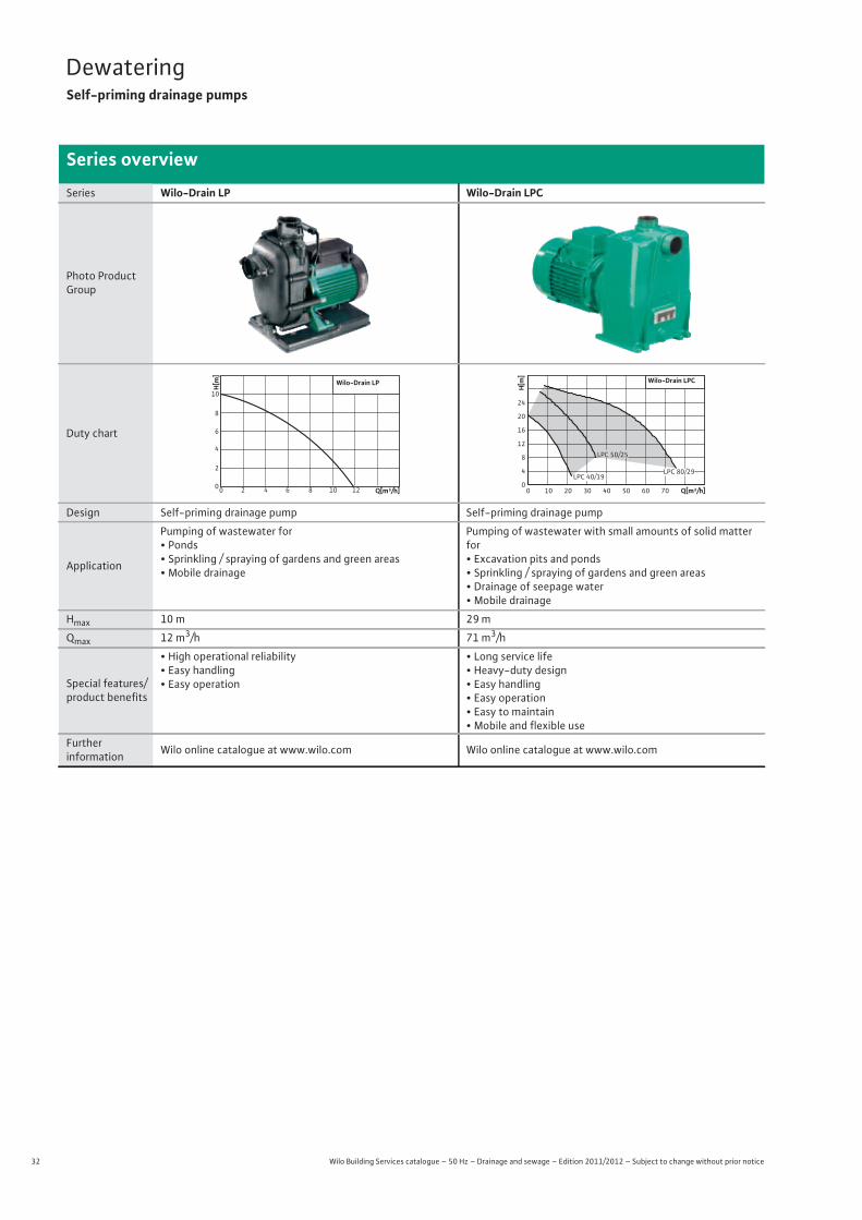
DewateringSelf-priming drainage pumps
Series overview
Series Wilo-Drain LP Wilo-Drain LPC
Photo Product Group
Duty chart
Design Self-priming drainage pump Self-priming drainage pump
Application
Pumping of wastewater for• Ponds• Sprinkling / spraying of gardens and green areas• Mobile drainage
Pumping of wastewater with small amounts of solid matter for• Excavation pits and ponds• Sprinkling / spraying of gardens and green areas• Drainage of seepage water• Mobile drainage
Hmax 10 m 29 m
Qmax 12 m3/h 71 m3/h
Special features/product benefits
• High operational reliability• Easy handling• Easy operation
• Long service life• Heavy-duty design• Easy handling• Easy operation• Easy to maintain• Mobile and flexible use
Furtherinformation Wilo online catalogue at www.wilo.com Wilo online catalogue at www.wilo.com
00 2 4 6 8 10 12
2
4
6
8
10
H[m]
Wilo-Drain LP
Q[m³/h] Q[m³/h]
H[m
]
0
4
8
12
16
20
24
0 10 20 30 40 50 60 70
Wilo-Drain LPC
LPC 50/25
LPC 40/19LPC 80/29
33
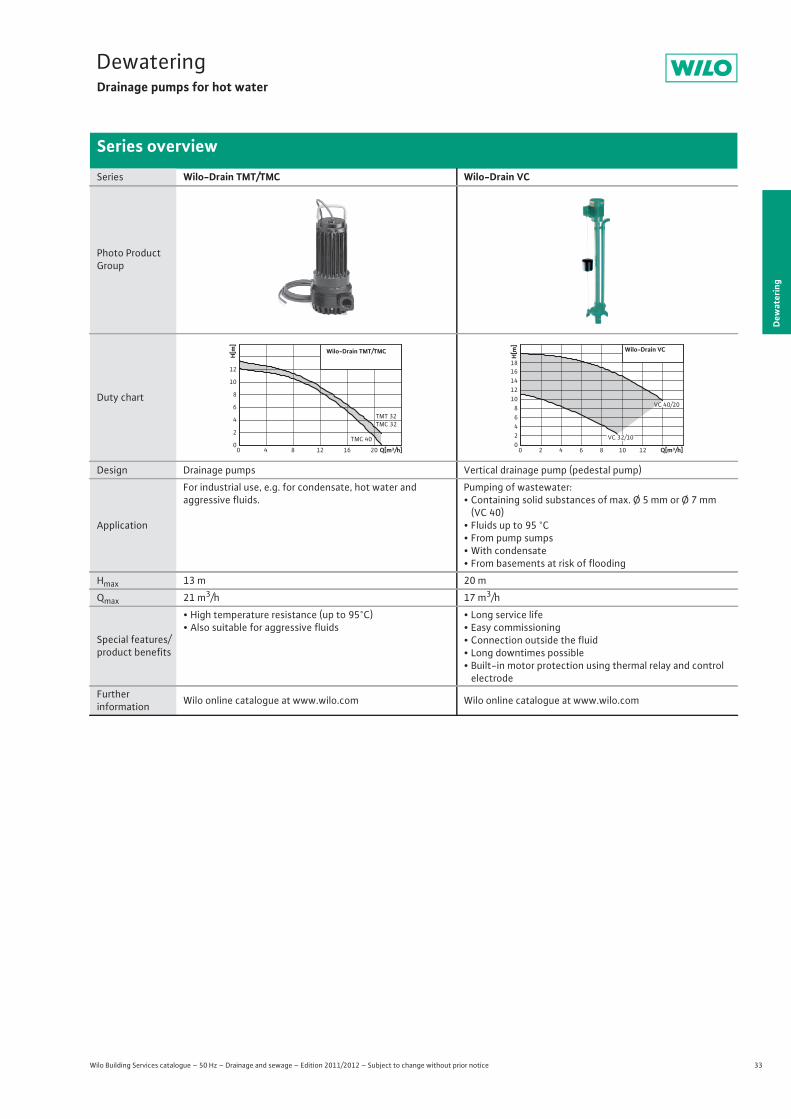
DewateringDrainage pumps for hot water
Wilo Building Services catalogue – 50 Hz – Drainage and sewage – Edition 2011/2012 – Subject to change without prior notice
Series overview
Dew
ater
ing
Series Wilo-Drain TMT/TMC Wilo-Drain VC
Photo Product Group
Duty chart
Design Drainage pumps Vertical drainage pump (pedestal pump)
Application
For industrial use, e.g. for condensate, hot water andaggressive fluids.
Pumping of wastewater:• Containing solid substances of max. Ø 5 mm or Ø 7 mm
(VC 40)• Fluids up to 95 °C• From pump sumps• With condensate• From basements at risk of flooding
Hmax 13 m 20 m
Qmax 21 m3/h 17 m3/h
Special features/product benefits
• High temperature resistance (up to 95°C)• Also suitable for aggressive fluids
• Long service life• Easy commissioning• Connection outside the fluid• Long downtimes possible• Built-in motor protection using thermal relay and control electrode
Furtherinformation Wilo online catalogue at www.wilo.com Wilo online catalogue at www.wilo.com
Q[m³/h]0 4 8 12 16 20
H[m
]
0
2
4
6
8
10
12
Wilo-Drain TMT/TMC
TMT 32TMC 32
TMC 40
Q[m³/h]0 2 4 6 8 10 12
H[m
]
02468
1012141618
Wilo-Drain VC
VC 40/20
VC 32/10
34 Wilo Building Services catalogue – 50 Hz – Drainage and sewage – Edition 2011/2012 – Subject to change without prior notice
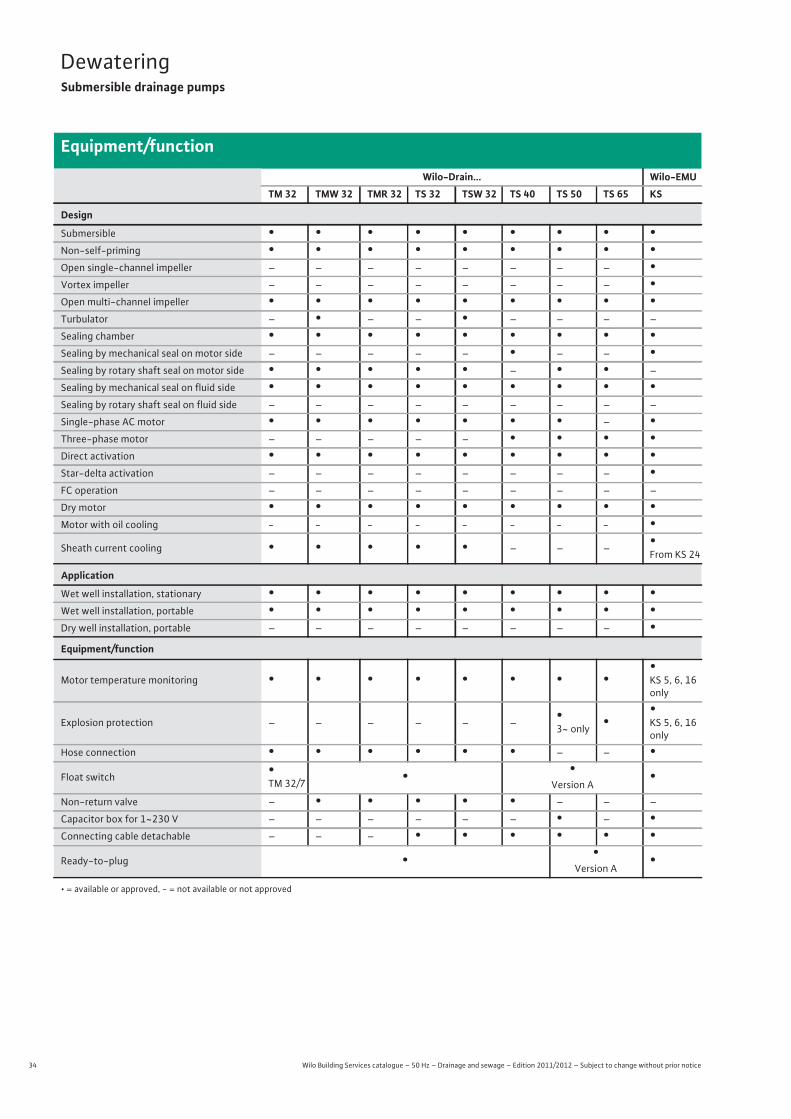
DewateringSubmersible drainage pumps
Equipment/function
Wilo-Drain... Wilo-EMUTM 32 TMW 32 TMR 32 TS 32 TSW 32 TS 40 TS 50 TS 65 KS
Design
Submersible • • • • • • • • •Non-self-priming • • • • • • • • •Open single-channel impeller – – – – – – – – •Vortex impeller – – – – – – – – •Open multi-channel impeller • • • • • • • • •Turbulator – • – – • – – – –
Sealing chamber • • • • • • • • •Sealing by mechanical seal on motor side – – – – – • – – •Sealing by rotary shaft seal on motor side • • • • • – • • –
Sealing by mechanical seal on fluid side • • • • • • • • •Sealing by rotary shaft seal on fluid side – – – – – – – – –
Single-phase AC motor • • • • • • • – •Three-phase motor – – – – – • • • •Direct activation • • • • • • • • •Star-delta activation – – – – – – – – •FC operation – – – – – – – – –
Dry motor • • • • • • • • •Motor with oil cooling - - - - - - - - •Sheath current cooling • • • • • – – – •
From KS 24
Application
Wet well installation, stationary • • • • • • • • •Wet well installation, portable • • • • • • • • •Dry well installation, portable – – – – – – – – •Equipment/function
Motor temperature monitoring • • • • • • • ••KS 5, 6, 16 only
Explosion protection – – – – – – •3~ only •
•KS 5, 6, 16 only
Hose connection • • • • • • – – •Float switch •
TM 32/7 • •Version A
•Non-return valve – • • • • • – – –
Capacitor box for 1~230 V – – – – – – • – •Connecting cable detachable – – – • • • • • •Ready-to-plug • •
Version A•
• = available or approved, - = not available or not approved
35
DewateringSubmersible drainage pumps
Dew
ater
ing
Series description Wilo-Drain TM/TMW/TMR 32
Wilo Building Services catalogue – 50 Hz – Drainage and sewage – Edition 2011/2012 – Subject to change without prior notice
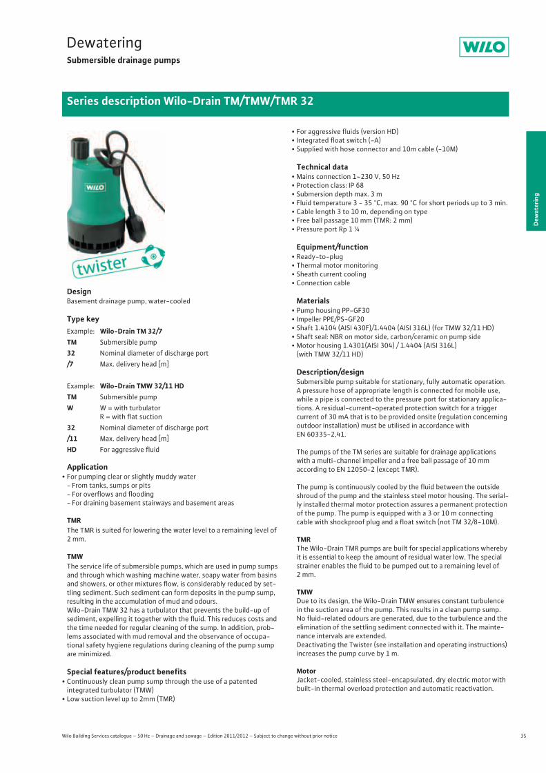
DesignBasement drainage pump, water-cooled
Type key
Application• For pumping clear or slightly muddy water
- From tanks, sumps or pits- For overflows and flooding- For draining basement stairways and basement areas
TMRThe TMR is suited for lowering the water level to a remaining level of 2 mm.
TMWThe service life of submersible pumps, which are used in pump sumps and through which washing machine water, soapy water from basins and showers, or other mixtures flow, is considerably reduced by set-tling sediment. Such sediment can form deposits in the pump sump, resulting in the accumulation of mud and odours.Wilo-Drain TMW 32 has a turbulator that prevents the build-up of sediment, expelling it together with the fluid. This reduces costs and the time needed for regular cleaning of the sump. In addition, prob-lems associated with mud removal and the observance of occupa-tional safety hygiene regulations during cleaning of the pump sump are minimized.
Special features/product benefits• Continuously clean pump sump through the use of a patented
integrated turbulator (TMW)• Low suction level up to 2mm (TMR)
• For aggressive fluids (version HD)• Integrated float switch (-A)• Supplied with hose connector and 10m cable (-10M)
Technical data• Mains connection 1~230 V, 50 Hz• Protection class: IP 68• Submersion depth max. 3 m• Fluid temperature 3 - 35 °C, max. 90 °C for short periods up to 3 min.• Cable length 3 to 10 m, depending on type• Free ball passage 10 mm (TMR: 2 mm)• Pressure port Rp 1 ¼
Equipment/function• Ready-to-plug• Thermal motor monitoring• Sheath current cooling• Connection cable
Materials• Pump housing PP-GF30• Impeller PPE/PS-GF20• Shaft 1.4104 (AISI 430F)/1.4404 (AISI 316L) (for TMW 32/11 HD)• Shaft seal: NBR on motor side, carbon/ceramic on pump side• Motor housing 1.4301(AISI 304) / 1.4404 (AISI 316L)
(with TMW 32/11 HD)
Description/designSubmersible pump suitable for stationary, fully automatic operation. A pressure hose of appropriate length is connected for mobile use, while a pipe is connected to the pressure port for stationary applica-tions. A residual-current-operated protection switch for a trigger current of 30 mA that is to be provided onsite (regulation concerning outdoor installation) must be utilised in accordance withEN 60335-2,41.
The pumps of the TM series are suitable for drainage applications with a multi-channel impeller and a free ball passage of 10 mmaccording to EN 12050-2 (except TMR).
The pump is continuously cooled by the fluid between the outside shroud of the pump and the stainless steel motor housing. The serial-ly installed thermal motor protection assures a permanent protection of the pump. The pump is equipped with a 3 or 10 m connectingcable with shockproof plug and a float switch (not TM 32/8-10M).
TMRThe Wilo-Drain TMR pumps are built for special applications whereby it is essential to keep the amount of residual water low. The special strainer enables the fluid to be pumped out to a remaining level of 2 mm.
TMWDue to its design, the Wilo-Drain TMW ensures constant turbulence in the suction area of the pump. This results in a clean pump sump.No fluid-related odours are generated, due to the turbulence and the elimination of the settling sediment connected with it. The mainte-nance intervals are extended.Deactivating the Twister (see installation and operating instructions) increases the pump curve by 1 m.
MotorJacket-cooled, stainless steel-encapsulated, dry electric motor with built-in thermal overload protection and automatic reactivation.
Example: Wilo-Drain TM 32/7TM Submersible pump32 Nominal diameter of discharge port/7 Max. delivery head [m]
Example: Wilo-Drain TMW 32/11 HDTM Submersible pumpW W = with turbulator
R = with flat suction32 Nominal diameter of discharge port /11 Max. delivery head [m]HD For aggressive fluid
36 Wilo Building Services catalogue – 50 Hz – Drainage and sewage – Edition 2011/2012 – Subject to change without prior notice
DewateringSubmersible drainage pumps
Series description Wilo-Drain TM/TMW/TMR 32
CableIn accordance with DIN EN 60335-2-41, 10 m of electrical connec-tion line should be used for outdoor operation (however note that regulations vary from country to country).
Sealing of pumps/motor compartmentMechanical seal on impeller side, one rotary shaft seal on motor side; there is an oil chamber between the seals.
Scope of deliveryPump ready for connection with cable, plug and attached float switch (except for TM 32/8), supplied non-return valve (except for TM 32/7), installation and operating instructions.
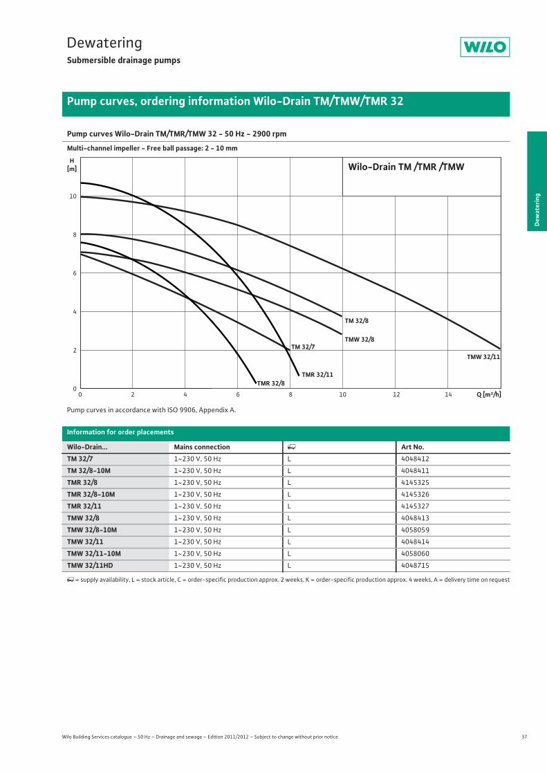
37
DewateringSubmersible drainage pumps
Dew
ater
ing
Pump curves, ordering information Wilo-Drain TM/TMW/TMR 32
Wilo Building Services catalogue – 50 Hz – Drainage and sewage – Edition 2011/2012 – Subject to change without prior notice
Pump curves Wilo-Drain TM/TMR/TMW 32 - 50 Hz - 2900 rpm
Multi-channel impeller - Free ball passage: 2 - 10 mm
Pump curves in accordance with ISO 9906, Appendix A.
Information for order placements
Wilo-Drain... Mains connection � Art No.TM 32/7 1~230 V, 50 Hz L 4048412
TM 32/8-10M 1~230 V, 50 Hz L 4048411
TMR 32/8 1~230 V, 50 Hz L 4145325
TMR 32/8-10M 1~230 V, 50 Hz L 4145326
TMR 32/11 1~230 V, 50 Hz L 4145327
TMW 32/8 1~230 V, 50 Hz L 4048413
TMW 32/8-10M 1~230 V, 50 Hz L 4058059
TMW 32/11 1~230 V, 50 Hz L 4048414
TMW 32/11-10M 1~230 V, 50 Hz L 4058060
TMW 32/11HD 1~230 V, 50 Hz L 4048715
�= supply availability, L = stock article, C = order-specific production approx. 2 weeks, K = order-specific production approx. 4 weeks, A = delivery time on request
10
0
2
4
6
8
0 2 4 6 8 10 12 14
TMW 32/8TM 32/7
TM 32/8
Wilo-Drain TM /TMR /TMWH[m]
Q [m³/h]
TMW 32/11
TMR 32/11TMR 32/8
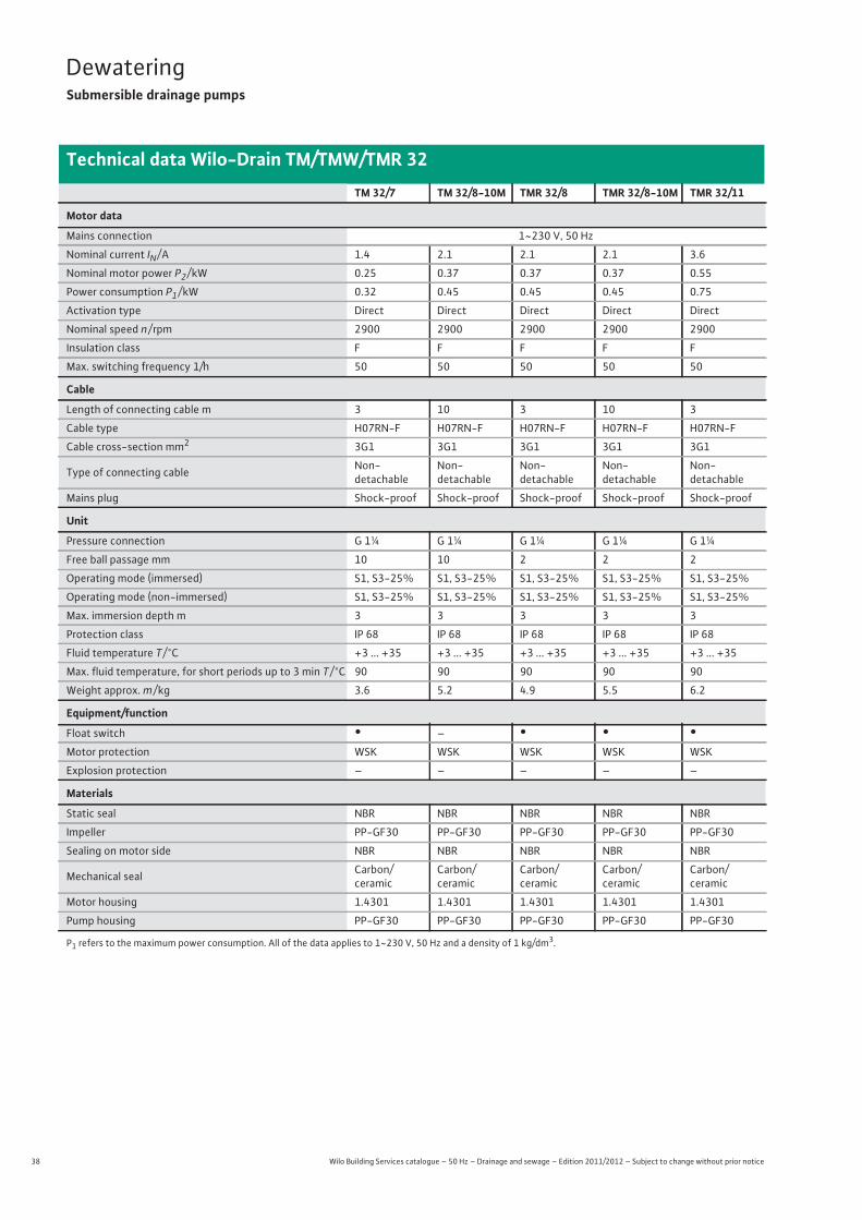
38 Wilo Building Services catalogue – 50 Hz – Drainage and sewage – Edition 2011/2012 – Subject to change without prior notice
DewateringSubmersible drainage pumps
Technical data Wilo-Drain TM/TMW/TMR 32
TM 32/7 TM 32/8-10M TMR 32/8 TMR 32/8-10M TMR 32/11
Motor data
Mains connection 1~230 V, 50 Hz
Nominal current IN / A 1.4 2.1 2.1 2.1 3.6
Nominal motor power P2 / kW 0.25 0.37 0.37 0.37 0.55
Power consumption P1 / kW 0.32 0.45 0.45 0.45 0.75
Activation type Direct Direct Direct Direct Direct
Nominal speed n / rpm 2900 2900 2900 2900 2900
Insulation class F F F F F
Max. switching frequency 1/h 50 50 50 50 50
Cable
Length of connecting cable m 3 10 3 10 3
Cable type H07RN-F H07RN-F H07RN-F H07RN-F H07RN-F
Cable cross-section mm2 3G1 3G1 3G1 3G1 3G1
Type of connecting cable Non-detachable
Non-detachable
Non-detachable
Non-detachable
Non-detachable
Mains plug Shock-proof Shock-proof Shock-proof Shock-proof Shock-proof
Unit
Pressure connection G 1¼ G 1¼ G 1¼ G 1¼ G 1¼
Free ball passage mm 10 10 2 2 2
Operating mode (immersed) S1, S3-25% S1, S3-25% S1, S3-25% S1, S3-25% S1, S3-25%
Operating mode (non-immersed) S1, S3-25% S1, S3-25% S1, S3-25% S1, S3-25% S1, S3-25%
Max. immersion depth m 3 3 3 3 3
Protection class IP 68 IP 68 IP 68 IP 68 IP 68
Fluid temperature T / °C +3 ... +35 +3 ... +35 +3 ... +35 +3 ... +35 +3 ... +35
Max. fluid temperature, for short periods up to 3 min T / °C 90 90 90 90 90
Weight approx. m / kg 3.6 5.2 4.9 5.5 6.2
Equipment/function
Float switch • – • • •Motor protection WSK WSK WSK WSK WSK
Explosion protection – – – – –
Materials
Static seal NBR NBR NBR NBR NBR
Impeller PP-GF30 PP-GF30 PP-GF30 PP-GF30 PP-GF30
Sealing on motor side NBR NBR NBR NBR NBR
Mechanical seal Carbon/ceramic
Carbon/ceramic
Carbon/ceramic
Carbon/ceramic
Carbon/ceramic
Motor housing 1.4301 1.4301 1.4301 1.4301 1.4301
Pump housing PP-GF30 PP-GF30 PP-GF30 PP-GF30 PP-GF30
P1 refers to the maximum power consumption. All of the data applies to 1~230 V, 50 Hz and a density of 1 kg/dm3.

39
DewateringSubmersible drainage pumps
Wilo Building Services catalogue – 50 Hz – Drainage and sewage – Edition 2011/2012 – Subject to change without prior notice
Technical data Wilo-Drain TM/TMW/TMR 32
Dew
ater
ing
TMW 32/8 TMW 32/8-10M TMW 32/11 TMW 32/11-10M TMW 32/11HD
Motor data
Mains connection 1~230 V, 50 Hz
Nominal current IN / A 2.1 2.1 3.6 3.6 3.6
Nominal motor power P2 / kW 0.37 0.37 0.55 0.55 0.55
Power consumption P1 / kW 0.45 0.45 0.75 0.75 0.75
Activation type Direct Direct Direct Direct Direct
Nominal speed n / rpm 2900 2900 2900 2900 2900
Insulation class F F F F F
Max. switching frequency 1/h 50 50 50 50 50
Cable
Length of connecting cable m 3 10 3 10 10
Cable type H07RN-F H07RN-F H07RN-F H07RN-F H07RN-F
Cable cross-section mm2 3G1 3G1 3G1 3G1 3G1
Type of connecting cable Non-detachable
Non-detachable
Non-detachable
Non-detachable
Non-detachable
Mains plug Shock-proof Shock-proof Shock-proof Shock-proof Shock-proof
Unit
Pressure connection G 1¼ G 1¼ G 1¼ G 1¼ G 1¼
Free ball passage mm 10 10 10 10 10
Operating mode (immersed) S1, S3-25% S1, S3-25% S1, S3-25% S1, S3-25% S1, S3-25%
Operating mode (non-immersed) S1, S3-25% S1, S3-25% S1, S3-25% S1, S3-25% S1, S3-25%
Max. immersion depth m 3 3 3 3 3
Protection class IP 68 IP 68 IP 68 IP 68 IP 68
Fluid temperature T / °C +3 ... +35 +3 ... +35 +3 ... +35 +3 ... +35 +3 ... +35
Max. fluid temperature, for short periods up to 3 min T / °C 90 90 90 90 90
Weight approx. m / kg 4.7 5.2 6.1 6.9 6.7
Equipment/function
Float switch • • • • •Motor protection WSK WSK WSK WSK WSK
Explosion protection – – – – –
Materials
Static seal NBR NBR NBR NBR NBR
Impeller PP-GF30 PP-GF30 PP-GF30 PP-GF30 PP-GF30
Sealing on motor side NBR NBR NBR NBR NBR
Mechanical seal Carbon/ce-ramic Carbon/ceramic Carbon/ce-
ramic Carbon/ceramic Carbon/ceram-ic
Motor housing 1.4301 1.4301 1.4301 1.4301 1.4404
Pump housing PP-GF30 PP-GF30 PP-GF30 PP-GF30 PP-GF30
P1 refers to the maximum power consumption. All of the data applies to 1~230 V, 50 Hz and a density of 1 kg/dm3.
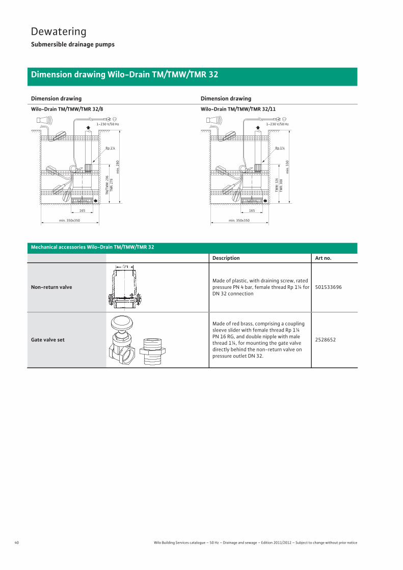
40 Wilo Building Services catalogue – 50 Hz – Drainage and sewage – Edition 2011/2012 – Subject to change without prior notice
DewateringSubmersible drainage pumps
Dimension drawing Wilo-Drain TM/TMW/TMR 32
Dimension drawing
Wilo-Drain TM/TMW/TMR 32/8
Dimension drawing
Wilo-Drain TM/TMW/TMR 32/11
Mechanical accessories Wilo-Drain TM/TMW/TMR 32
Description Art no.
Non-return valveMade of plastic, with draining screw, rated pressure PN 4 bar, female thread Rp 1¼ for DN 32 connection
501533696
Gate valve set
Made of red brass, comprising a coupling sleeve slider with female thread Rp 1¼ PN 16 RG, and double nipple with male thread 1¼, for mounting the gate valvedirectly behind the non-return valve on pressure outlet DN 32.
2528652
165
1~230 V/50 Hz
TM/T
MW
: 296
TMR:
278
min. 350x350
min
. 280
Rp 1¼
165
Rp 1¼
1~230 V/50 Hz
TMW
: 326
TMR:
308
min. 350x350
min
. 330
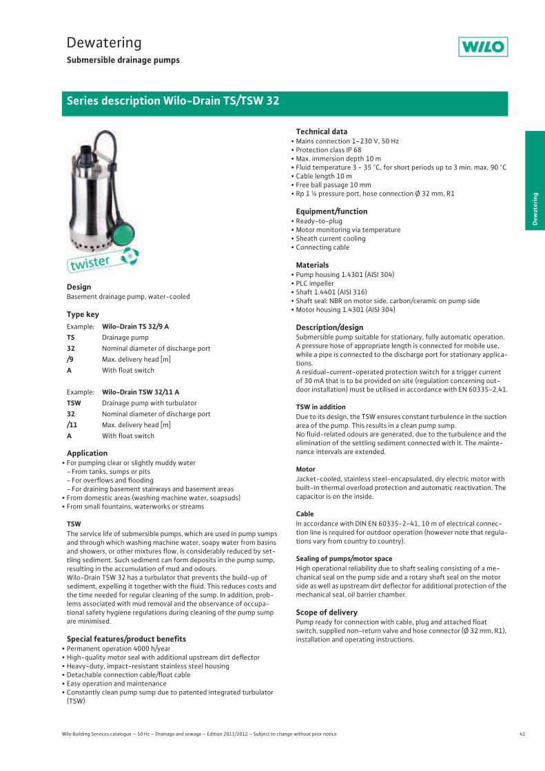
41
DewateringSubmersible drainage pumps
Dew
ater
ing
Series description Wilo-Drain TS/TSW 32
Wilo Building Services catalogue – 50 Hz – Drainage and sewage – Edition 2011/2012 – Subject to change without prior notice
DesignBasement drainage pump, water-cooled
Type key
Application• For pumping clear or slightly muddy water
- From tanks, sumps or pits- For overflows and flooding- For draining basement stairways and basement areas
• From domestic areas (washing machine water, soapsuds)• From small fountains, waterworks or streams
TSWThe service life of submersible pumps, which are used in pump sumps and through which washing machine water, soapy water from basins and showers, or other mixtures flow, is considerably reduced by set-tling sediment. Such sediment can form deposits in the pump sump, resulting in the accumulation of mud and odours.Wilo-Drain TSW 32 has a turbulator that prevents the build-up of sediment, expelling it together with the fluid. This reduces costs and the time needed for regular cleaning of the sump. In addition, prob-lems associated with mud removal and the observance of occupa-tional safety hygiene regulations during cleaning of the pump sump are minimised.
Special features/product benefits• Permanent operation 4000 h/year • High-quality motor seal with additional upstream dirt deflector• Heavy-duty, impact-resistant stainless steel housing • Detachable connection cable/float cable• Easy operation and maintenance• Constantly clean pump sump due to patented integrated turbulator
(TSW)
Technical data• Mains connection 1~230 V, 50 Hz• Protection class IP 68• Max. immersion depth 10 m• Fluid temperature 3 - 35 °C, for short periods up to 3 min. max. 90 °C• Cable length 10 m• Free ball passage 10 mm• Rp 1 ¼ pressure port, hose connection Ø 32 mm, R1
Equipment/function• Ready-to-plug• Motor monitoring via temperature• Sheath current cooling• Connecting cable
Materials• Pump housing 1.4301 (AISI 304)• PLC impeller• Shaft 1.4401 (AISI 316)• Shaft seal: NBR on motor side, carbon/ceramic on pump side• Motor housing 1.4301 (AISI 304)
Description/designSubmersible pump suitable for stationary, fully automatic operation. A pressure hose of appropriate length is connected for mobile use, while a pipe is connected to the discharge port for stationary applica-tions. A residual-current-operated protection switch for a trigger current of 30 mA that is to be provided on site (regulation concerning out-door installation) must be utilised in accordance with EN 60335-2,41.
TSW in additionDue to its design, the TSW ensures constant turbulence in the suction area of the pump. This results in a clean pump sump.No fluid-related odours are generated, due to the turbulence and the elimination of the settling sediment connected with it. The mainte-nance intervals are extended.
MotorJacket-cooled, stainless steel-encapsulated, dry electric motor with built-in thermal overload protection and automatic reactivation. The capacitor is on the inside.
CableIn accordance with DIN EN 60335-2-41, 10 m of electrical connec-tion line is required for outdoor operation (however note that regula-tions vary from country to country).
Sealing of pumps/motor spaceHigh operational reliability due to shaft sealing consisting of a me-chanical seal on the pump side and a rotary shaft seal on the motor side as well as upstream dirt deflector for additional protection of the mechanical seal, oil barrier chamber.
Scope of deliveryPump ready for connection with cable, plug and attached float switch, supplied non-return valve and hose connector (Ø 32 mm, R1), installation and operating instructions.
Example: Wilo-Drain TS 32/9 ATS Drainage pump 32 Nominal diameter of discharge port/9 Max. delivery head [m]A With float switch
Example: Wilo-Drain TSW 32/11 ATSW Drainage pump with turbulator32 Nominal diameter of discharge port /11 Max. delivery head [m]A With float switch
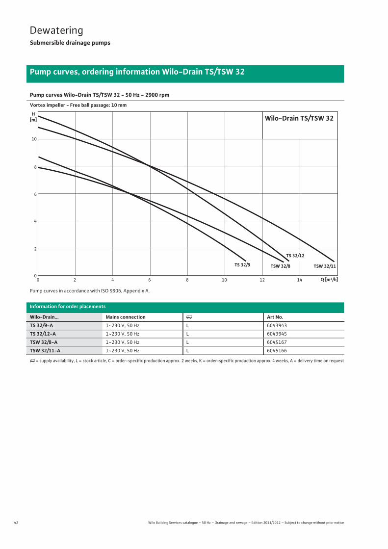
42 Wilo Building Services catalogue – 50 Hz – Drainage and sewage – Edition 2011/2012 – Subject to change without prior notice
DewateringSubmersible drainage pumps
Pump curves, ordering information Wilo-Drain TS/TSW 32
Pump curves Wilo-Drain TS/TSW 32 - 50 Hz - 2900 rpm
Vortex impeller - Free ball passage: 10 mm
Pump curves in accordance with ISO 9906, Appendix A.
Information for order placements
Wilo-Drain... Mains connection � Art No.TS 32/9-A 1~230 V, 50 Hz L 6043943
TS 32/12-A 1~230 V, 50 Hz L 6043945
TSW 32/8-A 1~230 V, 50 Hz L 6045167
TSW 32/11-A 1~230 V, 50 Hz L 6045166
�= supply availability, L = stock article, C = order-specific production approx. 2 weeks, K = order-specific production approx. 4 weeks, A = delivery time on request
TSW 32/11
TS 32/12
TSW 32/8TS 32/9
Wilo-Drain TS/TSW 32
4
0
8
10
6
2
H[m]
0 4 8 12 142 6 10 Q [m³/h]

43
DewateringSubmersible drainage pumps
Wilo Building Services catalogue – 50 Hz – Drainage and sewage – Edition 2011/2012 – Subject to change without prior notice
Technical data Wilo-Drain TS/TSW 32
Dew
ater
ing
TS 32/9-A TS 32/12-A TSW 32/8-A TSW 32/11-A
Motor data
Mains connection 1~230 V, 50 Hz
Nominal current IN / A 2.2 3.4 2.2 3.6
Nominal motor power P2 / kW 0.3 0.6 0.3 0.6
Power consumption P1 / kW 0.5 0.8 0.5 0.9
Activation type Direct Direct Direct Direct
Nominal speed n / rpm 2900 2900 2900 2900
Insulation class B B B B
Max. switching frequency 1/h 50 50 50 50
Cable
Length of connecting cable m 10 10 10 10
Cable type H07RN-F H07RN-F H07RN-F H07RN-F
Cable cross-section mm2 3G1 3G1 3G1 3G1
Type of connecting cable Detachable Detachable Detachable Detachable
Mains plug Shock-proof Shock-proof Shock-proof Shock-proof
Unit
Pressure connection Rp 1¼ Rp 1¼ Rp 1¼ Rp 1¼
Free ball passage mm 10 10 10 10
Operating mode (immersed) S1, S3-25% S1, S3-25% S1, S3-25% S1, S3-25%
Operating mode (non-immersed) S1, S3-25% S1, S3-25% S1, S3-25% S1, S3-25%
Max. immersion depth m 10 10 10 10
Protection class IP 68 IP 68 IP 68 IP 68
Fluid temperature T / °C +3 ... +35 +3 ... +35 +3 ... +35 +3 ... +35
Max. fluid temperature, for short periods up to 3 min T / °C – – – –
Weight approx. m / kg 6.8 7.8 6.8 7.8
Equipment/function
Float switch • • • •Motor protection WSK WSK WSK WSK
Explosion protection – – – –
Materials
Static seal NBR NBR NBR NBR
Impeller PLC PLC PLC PLC
Sealing on motor side NBR NBR NBR NBR
Mechanical seal Carbon/ceramic Carbon/ceramic Carbon/ceramic Carbon/ceramic
Motor housing 1.4301 1.4301 1.4301 1.4301
Pump housing 1.4301 1.4301 1.4301 1.4301
P1 refers to the maximum power consumption. All of the data applies to 1~230 V, 50 Hz and a density of 1 kg/dm3.
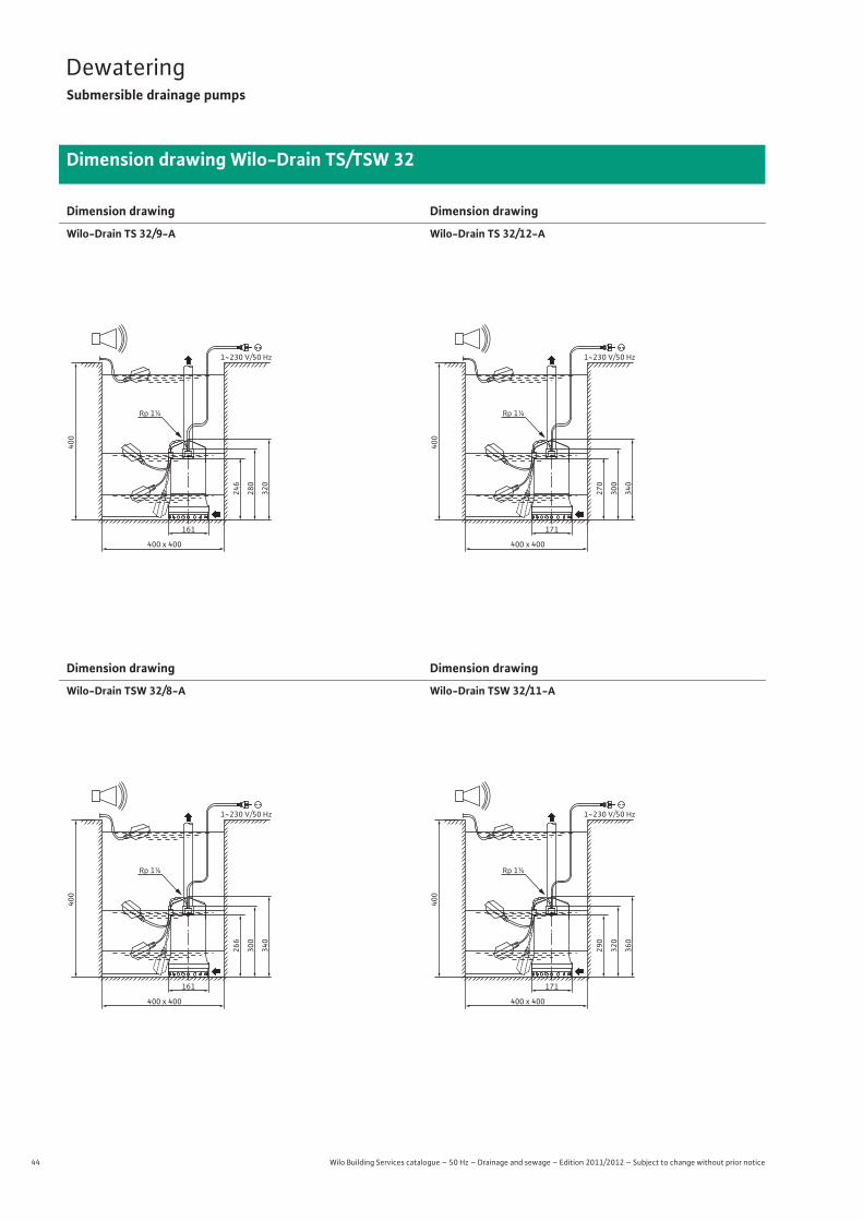
44 Wilo Building Services catalogue – 50 Hz – Drainage and sewage – Edition 2011/2012 – Subject to change without prior notice
DewateringSubmersible drainage pumps
Dimension drawing Wilo-Drain TS/TSW 32
Dimension drawing
Wilo-Drain TS 32/9-A
Dimension drawing
Wilo-Drain TS 32/12-A
Dimension drawing
Wilo-Drain TSW 32/8-A
Dimension drawing
Wilo-Drain TSW 32/11-A
1~230 V/50 Hz
320
280
246
161
400 x 400
400
Rp 1¼
1~230 V/50 Hz
340
300
270
171
400 x 400
400
Rp 1¼
1~230 V/50 Hz
340
300
266
161
400 x 400
400
Rp 1¼
1~230 V/50 Hz
360
320
290
171
400 x 400
400
Rp 1¼
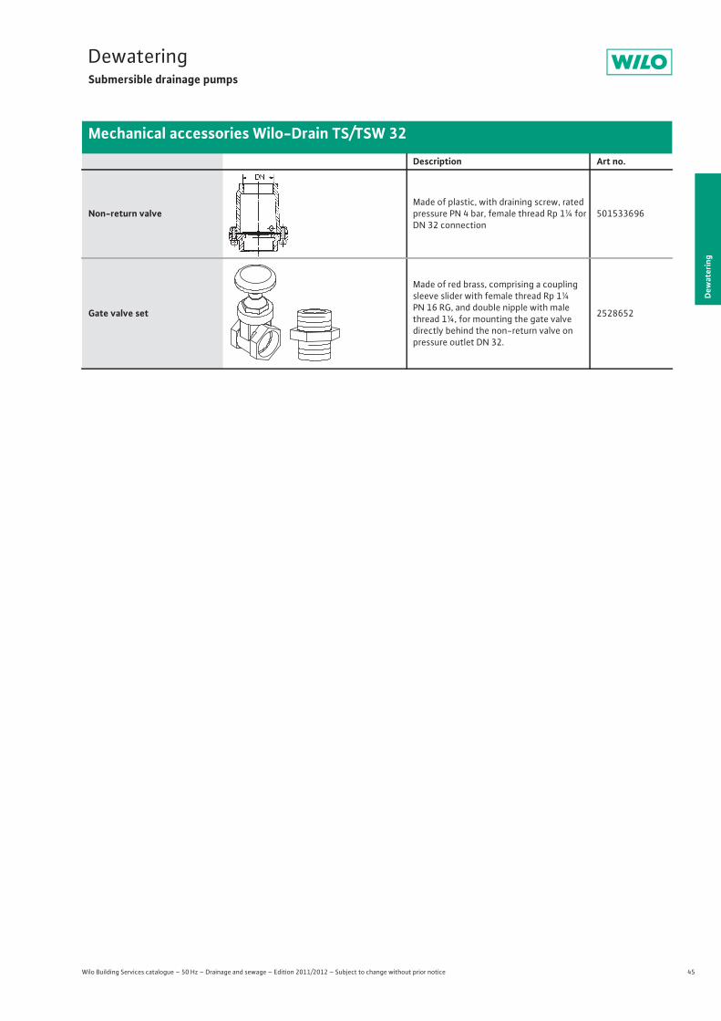
45
DewateringSubmersible drainage pumps
Wilo Building Services catalogue – 50 Hz – Drainage and sewage – Edition 2011/2012 – Subject to change without prior notice
Mechanical accessories Wilo-Drain TS/TSW 32
Dew
ater
ing
Description Art no.
Non-return valveMade of plastic, with draining screw, rated pressure PN 4 bar, female thread Rp 1¼ for DN 32 connection
501533696
Gate valve set
Made of red brass, comprising a coupling sleeve slider with female thread Rp 1¼ PN 16 RG, and double nipple with male thread 1¼, for mounting the gate valvedirectly behind the non-return valve on pressure outlet DN 32.
2528652
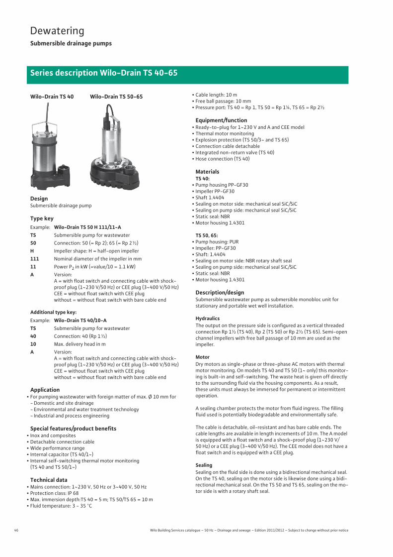
46 Wilo Building Services catalogue – 50 Hz – Drainage and sewage – Edition 2011/2012 – Subject to change without prior notice
DewateringSubmersible drainage pumps
Series description Wilo-Drain TS 40-65
DesignSubmersible drainage pump
Type key
Additional type key:
Application• For pumping wastewater with foreign matter of max. Ø 10 mm for
-Domestic and site drainage- Environmental and water treatment technology- Industrial and process engineering
Special features/product benefits• Inox and composites• Detachable connection cable• Wide performance range• Internal capacitor (TS 40/1~)• Internal self-switching thermal motor monitoring
(TS 40 and TS 50/1~)
Technical data• Mains connection: 1~230 V, 50 Hz or 3~400 V, 50 Hz• Protection class: IP 68• Max. immersion depth:TS 40 = 5 m; TS 50/TS 65 = 10 m• Fluid temperature: 3 - 35 °C
• Cable length: 10 m• Free ball passage: 10 mm• Pressure port: TS 40 = Rp 1, TS 50 = Rp 1¼, TS 65 = Rp 2½
Equipment/function• Ready-to-plug for 1~230 V and A and CEE model• Thermal motor monitoring• Explosion protection (TS 50/3~ and TS 65)• Connection cable detachable• Integrated non-return valve (TS 40)• Hose connection (TS 40)
MaterialsTS 40:
• Pump housing PP-GF30• Impeller PP-GF30• Shaft 1.4404• Sealing on motor side: mechanical seal SiC/SiC• Sealing on pump side: mechanical seal SiC/SiC• Static seal: NBR• Motor housing 1.4301
TS 50, 65:• Pump housing: PUR• Impeller: PP-GF30• Shaft: 1.4404• Sealing on motor side: NBR rotary shaft seal• Sealing on pump side: mechanical seal SiC/SiC• Static seal: NBR• Motor housing 1.4301
Description/designSubmersible wastewater pump as submersible monobloc unit forstationary and portable wet well installation.
HydraulicsThe output on the pressure side is configured as a vertical threaded connection Rp 1½ (TS 40), Rp 2 (TS 50) or Rp 2½ (TS 65). Semi-open channel impellers with free ball passage of 10 mm are used as theimpeller.
MotorDry motors as single-phase or three-phase AC motors with thermal motor monitoring. On models TS 40 and TS 50 (1~ only) this monitor-ing is built-in and self-switching. The waste heat is given off directly to the surrounding fluid via the housing components. As a result, these units must always be immersed for permanent or intermittent operation.
A sealing chamber protects the motor from fluid ingress. The filling fluid used is potentially biodegradable and environmentally safe.
The cable is detachable, oil-resistant and has bare cable ends. The cable lengths are available in length increments of 10 m. The A model is equipped with a float switch and a shock-proof plug (1~230 V/50 Hz) or a CEE plug (3~400 V/50 Hz). The CEE model does not have a float switch and is equipped with a CEE plug.
SealingSealing on the fluid side is done using a bidirectional mechanical seal. On the TS 40, sealing on the motor side is likewise done using a bidi-rectional mechanical seal. On the TS 50 and TS 65, sealing on the mo-tor side is with a rotary shaft seal.
Example: Wilo-Drain TS 50 H 111/11-ATS Submersible pump for wastewater50 Connection: 50 (= Rp 2); 65 (= Rp 2 ½)H Impeller shape: H = half-open impeller111 Nominal diameter of the impeller in mm11 Power P2 in kW (=value/10 = 1.1 kW)A Version:
A = with float switch and connecting cable with shock-proof plug (1~230 V/50 Hz) or CEE plug (3~400 V/50 Hz)CEE = without float switch with CEE plugwithout = without float switch with bare cable end
Example: Wilo-Drain TS 40/10-ATS Submersible pump for wastewater40 Connection: 40 (Rp 1 ½)10 Max. delivery head in mA Version:
A = with float switch and connecting cable with shock-proof plug (1~230 V/50 Hz) or CEE plug (3~400 V/50 Hz)CEE = without float switch with CEE plugwithout = without float switch with bare cable end
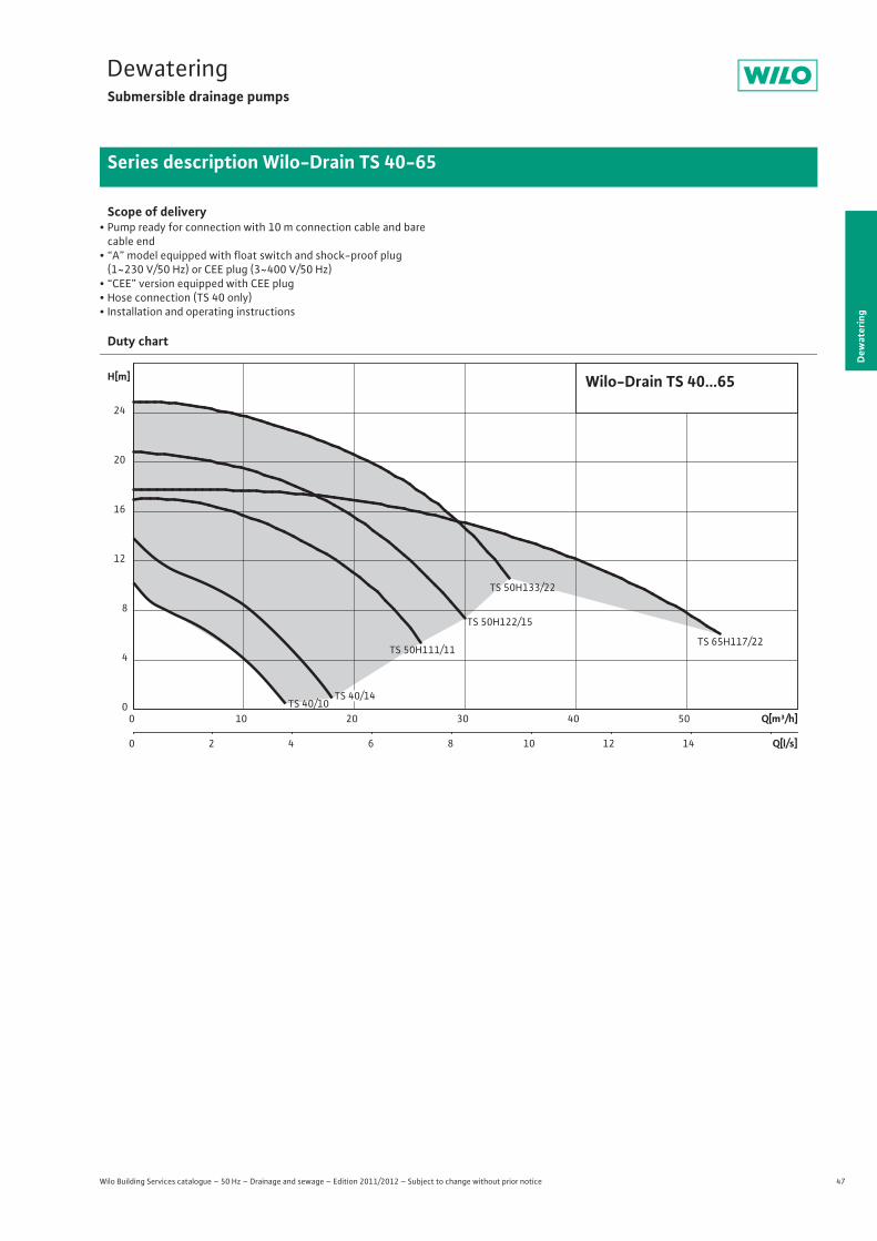
47
DewateringSubmersible drainage pumps
Dew
ater
ing
Series description Wilo-Drain TS 40-65
Wilo Building Services catalogue – 50 Hz – Drainage and sewage – Edition 2011/2012 – Subject to change without prior notice
Scope of delivery• Pump ready for connection with 10 m connection cable and barecable end
• “A” model equipped with float switch and shock-proof plug (1~230 V/50 Hz) or CEE plug (3~400 V/50 Hz)
• “CEE” version equipped with CEE plug• Hose connection (TS 40 only)• Installation and operating instructions
Duty chart
TS 50H133/22
TS 50H122/15
TS 65H117/22 TS 50H111/11
TS 40/10Q[m³/h]0 10 20 30 40 50
Q[l/s]0 2 4 6 8 10 12 14
H[m]
0
4
8
12
16
20
24
TS 40/14
Wilo-Drain TS 40...65

48 Wilo Building Services catalogue – 50 Hz – Drainage and sewage – Edition 2011/2012 – Subject to change without prior notice
DewateringSubmersible drainage pumps
Pump curves, ordering information Wilo-Drain TS 40
Pump curves Wilo-Drain TS 40 - 50 Hz - 2900 rpm
Single-channel impeller - Free ball passage: 10 mm
Pump curves in accordance with ISO 9906, Appendix A.
Information for order placements
Wilo-Drain... Mains connection � Art No.TS 40/10 1~230 V, 50 Hz L 2063928
TS 40/10-A 1~230 V, 50 Hz L 2063926
TS 40/10 3~400 V, 50 Hz L 2063927
TS 40/14 1~230 V, 50 Hz L 2063931
TS 40/14-A 1~230 V, 50 Hz L 2063929
TS 40/14 3~400 V, 50 Hz L 2063930
�= supply availability, L = stock article, C = order-specific production approx. 2 weeks, K = order-specific production approx. 4 weeks, A = delivery time on request
4
0
8
12
10
6
2
14
Wilo-Drain TS 40
0 4 8 12 162 6 10 14 18
H[m]
Q [m³/h]
TS 40/14TS 40/10

49
DewateringSubmersible drainage pumps
Wilo Building Services catalogue – 50 Hz – Drainage and sewage – Edition 2011/2012 – Subject to change without prior notice
Technical data Wilo-Drain TS 40
Dew
ater
ing
TS 40/10 TS 40/10 TS 40/10-A
Motor data
Mains connection 1~230 V, 50 Hz 3~400 V, 50 Hz 1~230 V, 50 Hz
Nominal current IN / A 2.2 1.1 2.2
Nominal motor power P2 / kW 0.4 0.4 0.4
Power consumption P1 / kW 0.48 0.55 0.48
Activation type Direct Direct Direct
Nominal speed n / rpm 2900 2900 2900
Insulation class B B B
Max. switching frequency 1/h 50 50 50
Cable
Length of connecting cable m 10 10 10
Cable type H07RN-F H07RN-F H07RN-F
Cable cross-section mm2 3G1 4G1 3G1
Type of connecting cable Plug, detachable Plug, detachable Plug, detachable
Mains plug Shock-proof – Shock-proof
Unit
Pressure connection Rp 1½ Rp 1½ Rp 1½
Free ball passage mm 10 10 10
Operating mode (immersed) S1, S3-25% S1, S3-25% S1, S3-25%
Operating mode (non-immersed) – – –
Max. immersion depth m 5 5 5
Protection class IP 68 IP 68 IP 68
Fluid temperature T / °C +3 ... +35 +3 ... +35 +3 ... +35
Max. fluid temperature, for short periods up to 3 min T / °C – – –
Weight approx. m / kg 14 14 14.2
Equipment/function
Float switch – – •Motor protection WSK WSK WSK
Explosion protection – – –
Materials
Static seal NBR NBR NBR
Impeller PP-GF30 PP-GF30 PP-GF30
Sealing on motor side SiC/SiC SiC/SiC SiC/SiC
Mechanical seal SiC/SiC SiC/SiC SiC/SiC
Motor housing 1.4301 1.4301 1.4301
Pump housing PP-GF30 PP-GF30 PP-GF30
P1 refers to the maximum power consumption. All of the data apply to 1~230 V or 3~400 V, 50 Hz and a density of 1 kg/dm3.
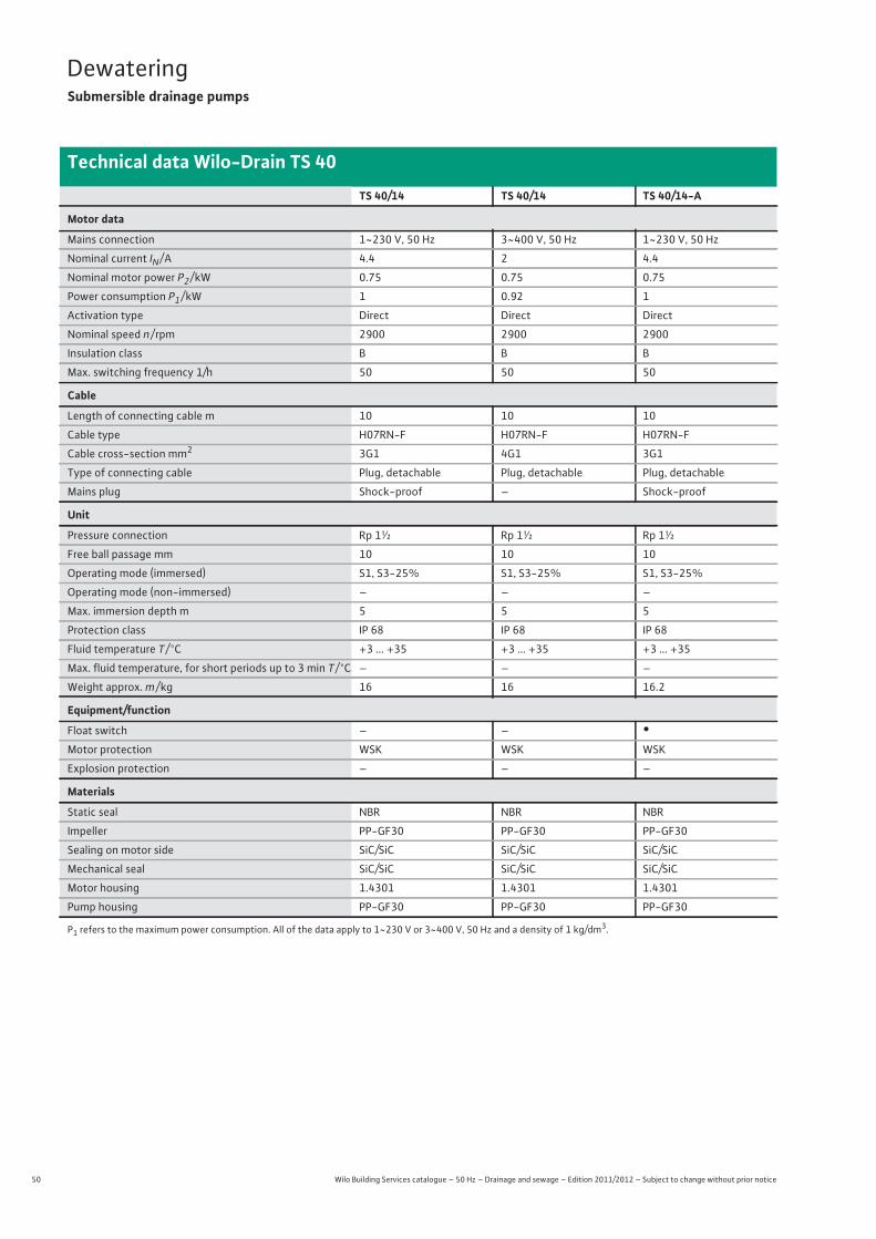
50 Wilo Building Services catalogue – 50 Hz – Drainage and sewage – Edition 2011/2012 – Subject to change without prior notice
DewateringSubmersible drainage pumps
Technical data Wilo-Drain TS 40
TS 40/14 TS 40/14 TS 40/14-A
Motor data
Mains connection 1~230 V, 50 Hz 3~400 V, 50 Hz 1~230 V, 50 Hz
Nominal current IN / A 4.4 2 4.4
Nominal motor power P2 / kW 0.75 0.75 0.75
Power consumption P1 / kW 1 0.92 1
Activation type Direct Direct Direct
Nominal speed n / rpm 2900 2900 2900
Insulation class B B B
Max. switching frequency 1/h 50 50 50
Cable
Length of connecting cable m 10 10 10
Cable type H07RN-F H07RN-F H07RN-F
Cable cross-section mm2 3G1 4G1 3G1
Type of connecting cable Plug, detachable Plug, detachable Plug, detachable
Mains plug Shock-proof – Shock-proof
Unit
Pressure connection Rp 1½ Rp 1½ Rp 1½
Free ball passage mm 10 10 10
Operating mode (immersed) S1, S3-25% S1, S3-25% S1, S3-25%
Operating mode (non-immersed) – – –
Max. immersion depth m 5 5 5
Protection class IP 68 IP 68 IP 68
Fluid temperature T / °C +3 ... +35 +3 ... +35 +3 ... +35
Max. fluid temperature, for short periods up to 3 min T / °C – – –
Weight approx. m / kg 16 16 16.2
Equipment/function
Float switch – – •Motor protection WSK WSK WSK
Explosion protection – – –
Materials
Static seal NBR NBR NBR
Impeller PP-GF30 PP-GF30 PP-GF30
Sealing on motor side SiC/SiC SiC/SiC SiC/SiC
Mechanical seal SiC/SiC SiC/SiC SiC/SiC
Motor housing 1.4301 1.4301 1.4301
Pump housing PP-GF30 PP-GF30 PP-GF30
P1 refers to the maximum power consumption. All of the data apply to 1~230 V or 3~400 V, 50 Hz and a density of 1 kg/dm3.
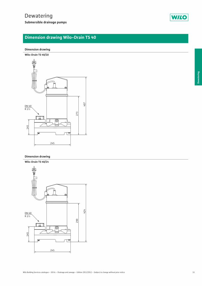
51
DewateringSubmersible drainage pumps
Dew
ater
ing
Dimension drawing Wilo-Drain TS 40
Wilo Building Services catalogue – 50 Hz – Drainage and sewage – Edition 2011/2012 – Subject to change without prior notice
Dimension drawing
Wilo-Drain TS 40/10
Dimension drawing
Wilo-Drain TS 40/14
145
245
273
407
DN 40R 1½
145
245
290
424
DN 40R 1½
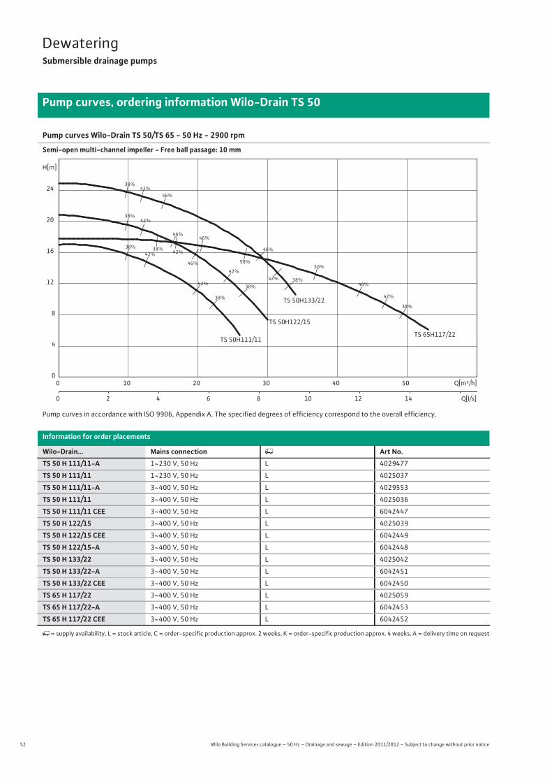
52 Wilo Building Services catalogue – 50 Hz – Drainage and sewage – Edition 2011/2012 – Subject to change without prior notice
DewateringSubmersible drainage pumps
Pump curves, ordering information Wilo-Drain TS 50
Pump curves Wilo-Drain TS 50/TS 65 - 50 Hz - 2900 rpm
Semi-open multi-channel impeller - Free ball passage: 10 mm
Pump curves in accordance with ISO 9906, Appendix A. The specified degrees of efficiency correspond to the overall efficiency.
Information for order placements
Wilo-Drain... Mains connection � Art No.TS 50 H 111/11-A 1~230 V, 50 Hz L 4029477
TS 50 H 111/11 1~230 V, 50 Hz L 4025037
TS 50 H 111/11-A 3~400 V, 50 Hz L 4029553
TS 50 H 111/11 3~400 V, 50 Hz L 4025036
TS 50 H 111/11 CEE 3~400 V, 50 Hz L 6042447
TS 50 H 122/15 3~400 V, 50 Hz L 4025039
TS 50 H 122/15 CEE 3~400 V, 50 Hz L 6042449
TS 50 H 122/15-A 3~400 V, 50 Hz L 6042448
TS 50 H 133/22 3~400 V, 50 Hz L 4025042
TS 50 H 133/22-A 3~400 V, 50 Hz L 6042451
TS 50 H 133/22 CEE 3~400 V, 50 Hz L 6042450
TS 65 H 117/22 3~400 V, 50 Hz L 4025059
TS 65 H 117/22-A 3~400 V, 50 Hz L 6042453
TS 65 H 117/22 CEE 3~400 V, 50 Hz L 6042452
�= supply availability, L = stock article, C = order-specific production approx. 2 weeks, K = order-specific production approx. 4 weeks, A = delivery time on request
38%
38%
38%
38%
38%
38%
38%
38%
42%
42%
42%
42%
42%
42%
42%
42%
46%
46%
46%
46%
46%
46% 50%50%
TS 50H133/22
TS 50H122/15
TS 65H117/22 TS 50H111/11
Q[m³/h]0 10 20 30 40 50
Q[l/s]0 2 4 6 8 10 12 14
H[m]
0
4
8
12
16
20
24

53
DewateringSubmersible drainage pumps
Wilo Building Services catalogue – 50 Hz – Drainage and sewage – Edition 2011/2012 – Subject to change without prior notice
Technical data Wilo-Drain TS 50
Dew
ater
ing
TS 50 H 111/11 TS 50 H 111/11 TS 50 H 111/11-A TS 50 H 111/11-A
Motor data
Mains connection 1~230 V, 50 Hz 3~400 V, 50 Hz 1~230 V, 50 Hz 3~400 V, 50 Hz
Nominal current IN / A 7.7 3.2 7.7 3.2
Nominal motor power P2 / kW 1.1 1.1 1.1 1.1
Power consumption P1 / kW 1.5 1.5 1.5 1.5
Activation type Direct Direct Direct Direct
Nominal speed n / rpm 2900 2900 2900 2900
Insulation class F F F F
Max. switching frequency 1/h 50 50 50 50
Cable
Length of connecting cable m 10 10 10 10
Cable type H07RN-F H07RN-F H07RN-F H07RN-F
Cable cross-section mm2 4G1 6G1 4G1 6G1
Type of connecting cable Plug, detachable Plug, detachable Plug, detachable Plug, detachable
Mains plug Shock-proof – Shock-proof CEE M 16 WDSHA
Unit
Pressure connection Rp 2 Rp 2 Rp 2 Rp 2
Free ball passage mm 10 10 10 10
Operating mode (immersed) S1, S3-25% S1, S3-25% S1, S3-25% S1, S3-25%
Operating mode (non-immersed) S2-8 min. S2-8 min. S2-8 min. S2-8 min.
Max. immersion depth m 10 10 10 10
Protection class IP 68 IP 68 IP 68 IP 68
Fluid temperature T / °C +3 ... +35 +3 ... +35 +3 ... +35 +3 ... +35
Max. fluid temperature, for short periods up to 3 min T / °C – – – –
Weight approx. m / kg 21 21 21 21
Equipment/function
Float switch – – • •Motor protection WSK WSK WSK WSK
Explosion protection – ATEX – –
Materials
Static seal NBR NBR NBR NBR
Impeller PP-GF30 PP-GF30 PP-GF30 PP-GF30
Sealing on motor side NBR NBR NBR NBR
Mechanical seal SiC/SiC SiC/SiC SiC/SiC SiC/SiC
Motor housing 1.4301 1.4301 1.4301 1.4301
Pump housing PUR PUR PUR PUR
P1 refers to the maximum power consumption. All of the data apply to 1~230 V or 3~400 V, 50 Hz and a density of 1 kg/dm3.
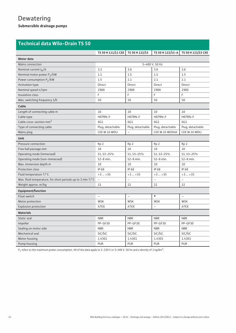
54 Wilo Building Services catalogue – 50 Hz – Drainage and sewage – Edition 2011/2012 – Subject to change without prior notice
DewateringSubmersible drainage pumps
Technical data Wilo-Drain TS 50
TS 50 H 111/11 CEE TS 50 H 122/15 TS 50 H 122/15-A TS 50 H 122/15 CEE
Motor data
Mains connection 3~400 V, 50 Hz
Nominal current IN / A 3.2 3.6 3.6 3.6
Nominal motor power P2 / kW 1.1 1.5 1.5 1.5
Power consumption P1 / kW 1.5 2.1 2.1 2.1
Activation type Direct Direct Direct Direct
Nominal speed n / rpm 2900 2900 2900 2900
Insulation class F F F F
Max. switching frequency 1/h 50 50 50 50
Cable
Length of connecting cable m 10 10 10 10
Cable type H07RN-F H07RN-F H07RN-F H07RN-F
Cable cross-section mm2 6G1 6G1 6G1 6G1
Type of connecting cable Plug, detachable Plug, detachable Plug, detachable Plug, detachable
Mains plug CEE M 16 WDU – CEE M 16 WDSHA CEE M 16 WDU
Unit
Pressure connection Rp 2 Rp 2 Rp 2 Rp 2
Free ball passage mm 10 10 10 10
Operating mode (immersed) S1, S3-25% S1, S3-25% S1, S3-25% S1, S3-25%
Operating mode (non-immersed) S2-8 min. S2-8 min. S2-8 min. S2-8 min.
Max. immersion depth m 10 10 10 10
Protection class IP 68 IP 68 IP 68 IP 68
Fluid temperature T / °C +3 ... +35 +3 ... +35 +3 ... +35 +3 ... +35
Max. fluid temperature, for short periods up to 3 min T / °C – – – –
Weight approx. m / kg 21 22 22 22
Equipment/function
Float switch – – • –
Motor protection WSK WSK WSK WSK
Explosion protection ATEX ATEX – ATEX
Materials
Static seal NBR NBR NBR NBR
Impeller PP-GF30 PP-GF30 PP-GF30 PP-GF30
Sealing on motor side NBR NBR NBR NBR
Mechanical seal SiC/SiC SiC/SiC SiC/SiC SiC/SiC
Motor housing 1.4301 1.4301 1.4301 1.4301
Pump housing PUR PUR PUR PUR
P1 refers to the maximum power consumption. All of the data apply to 1~230 V or 3~400 V, 50 Hz and a density of 1 kg/dm3.

55
DewateringSubmersible drainage pumps
Wilo Building Services catalogue – 50 Hz – Drainage and sewage – Edition 2011/2012 – Subject to change without prior notice
Technical data Wilo-Drain TS 50
Dew
ater
ing
TS 50 H 133/22 TS 50 H 133/22-A TS 50 H 133/22 CEE
Motor data
Mains connection 3~400 V, 50 Hz
Nominal current IN / A 5.1 5.1 5.1
Nominal motor power P2 / kW 2.2 2.2 2.2
Power consumption P1 / kW 2.9 2.9 2.9
Activation type Direct Direct Direct
Nominal speed n / rpm 2900 2900 2900
Insulation class F F F
Max. switching frequency 1/h 50 50 50
Cable
Length of connecting cable m 10 10 10
Cable type H07RN-F H07RN-F H07RN-F
Cable cross-section mm2 6G1 6G1 6G1
Type of connecting cable Plug, detachable Plug, detachable Plug, detachable
Mains plug – CEE M 16 WDSHA CEE M 16 WDU
Unit
Pressure connection Rp 2 Rp 2 Rp 2
Free ball passage mm 10 10 10
Operating mode (immersed) S1, S3-25% S1, S3-25% S1, S3-25%
Operating mode (non-immersed) S2-8 min. S2-8 min. S2-8 min.
Max. immersion depth m 10 10 10
Protection class IP 68 IP 68 IP 68
Fluid temperature T / °C +3 ... +35 +3 ... +35 +3 ... +35
Max. fluid temperature, for short periods up to 3 min T / °C – – –
Weight approx. m / kg 23 23 23
Equipment/function
Float switch – • –
Motor protection WSK WSK WSK
Explosion protection ATEX – ATEX
Materials
Static seal NBR NBR NBR
Impeller PP-GF30 PP-GF30 PP-GF30
Sealing on motor side NBR NBR NBR
Mechanical seal SiC/SiC SiC/SiC SiC/SiC
Motor housing 1.4301 1.4301 1.4301
Pump housing PUR PUR PUR
P1 refers to the maximum power consumption. All of the data apply to 1~230 V or 3~400 V, 50 Hz and a density of 1 kg/dm3.
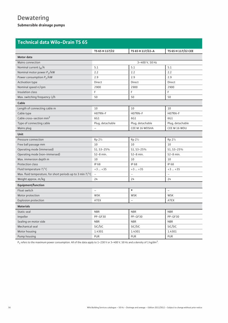
56 Wilo Building Services catalogue – 50 Hz – Drainage and sewage – Edition 2011/2012 – Subject to change without prior notice
DewateringSubmersible drainage pumps
Technical data Wilo-Drain TS 65
TS 65 H 117/22 TS 65 H 117/22-A TS 65 H 117/22 CEE
Motor data
Mains connection 3~400 V, 50 Hz
Nominal current IN / A 5.1 5.1 5.1
Nominal motor power P2 / kW 2.2 2.2 2.2
Power consumption P1 / kW 2.9 2.9 2.9
Activation type Direct Direct Direct
Nominal speed n / rpm 2900 2900 2900
Insulation class F F F
Max. switching frequency 1/h 50 50 50
Cable
Length of connecting cable m 10 10 10
Cable type H07RN-F H07RN-F H07RN-F
Cable cross-section mm2 6G1 6G1 6G1
Type of connecting cable Plug, detachable Plug, detachable Plug, detachable
Mains plug – CEE M 16 WDSHA CEE M 16 WDU
Unit
Pressure connection Rp 2½ Rp 2½ Rp 2½
Free ball passage mm 10 10 10
Operating mode (immersed) S1, S3-25% S1, S3-25% S1, S3-25%
Operating mode (non-immersed) S2-8 min. S2-8 min. S2-8 min.
Max. immersion depth m 10 10 10
Protection class IP 68 IP 68 IP 68
Fluid temperature T / °C +3 ... +35 +3 ... +35 +3 ... +35
Max. fluid temperature, for short periods up to 3 min T / °C – – –
Weight approx. m / kg 24 24 24
Equipment/function
Float switch – • –
Motor protection WSK WSK WSK
Explosion protection ATEX – ATEX
Materials
Static seal NBR NBR NBR
Impeller PP-GF30 PP-GF30 PP-GF30
Sealing on motor side NBR NBR NBR
Mechanical seal SiC/SiC SiC/SiC SiC/SiC
Motor housing 1.4301 1.4301 1.4301
Pump housing PUR PUR PUR
P1 refers to the maximum power consumption. All of the data apply to 1~230 V or 3~400 V, 50 Hz and a density of 1 kg/dm3.
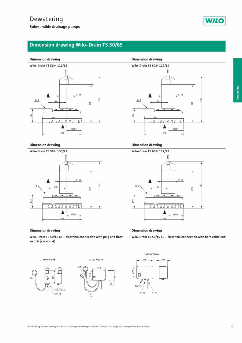
57
DewateringSubmersible drainage pumps
Dew
ater
ing
Dimension drawing Wilo-Drain TS 50/65
Wilo Building Services catalogue – 50 Hz – Drainage and sewage – Edition 2011/2012 – Subject to change without prior notice
Dimension drawing
Wilo-Drain TS 50 H 111/11
Dimension drawing
Wilo-Drain TS 50 H 122/15
Dimension drawing
Wilo-Drain TS 50 H 133/22
Dimension drawing
Wilo-Drain TS 65 H 117/22
Dimension drawing
Wilo-Drain TS 50/TS 65 - electrical connection with plug and float switch (version A)
Dimension drawing
Wilo-Drain TS 50/TS 65 - electrical connection with bare cable end
Ø294
132
360 44
0Rp 2
Ø128
170
375
Ø294
132
360 44
0
Rp 2
Ø128
170
375
Ø294
132
387 47
2
Rp 2
Ø138
170
375
Ø294
149
398 48
3
Rp 2½
Ø138
170
375
PG 11
PG 16-21
225
110
10m
80
120
80
15010m
1m
3~400 V/50 Hz 1~230 V/50 Hz
PG 11 PG 13
PG 13
1~230 V/50 Hz
120
150 80
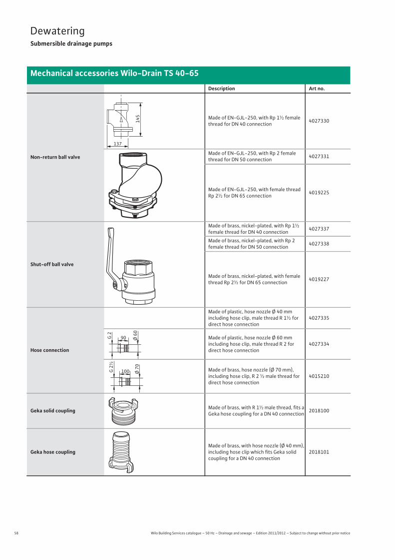
58 Wilo Building Services catalogue – 50 Hz – Drainage and sewage – Edition 2011/2012 – Subject to change without prior notice
DewateringSubmersible drainage pumps
Mechanical accessories Wilo-Drain TS 40-65
Description Art no.
Non-return ball valve
Made of EN-GJL-250, with Rp 1½ female thread for DN 40 connection 4027330
Made of EN-GJL-250, with Rp 2 female thread for DN 50 connection 4027331
Made of EN-GJL-250, with female thread Rp 2½ for DN 65 connection 4019225
Shut-off ball valve
Made of brass, nickel-plated, with Rp 1½ female thread for DN 40 connection 4027337
Made of brass, nickel-plated, with Rp 2female thread for DN 50 connection 4027338
Made of brass, nickel-plated, with female thread Rp 2½ for DN 65 connection 4019227
Hose connection
Made of plastic, hose nozzle Ø 40 mmincluding hose clip, male thread R 1½ for direct hose connection
4027335
Made of plastic, hose nozzle Ø 60 mmincluding hose clip, male thread R 2 fordirect hose connection
4027334
Made of brass, hose nozzle (Ø 70 mm),including hose clip, R 2 ½ male thread for direct hose connection
4015210
Geka solid coupling Made of brass, with R 1½ male thread, fits a Geka hose coupling for a DN 40 connection 2018100
Geka hose couplingMade of brass, with hose nozzle (Ø 40 mm), including hose clip which fits Geka solid coupling for a DN 40 connection
2018101
145
137
90 Ø 60
G 2
100 Ø 70
G 2
½
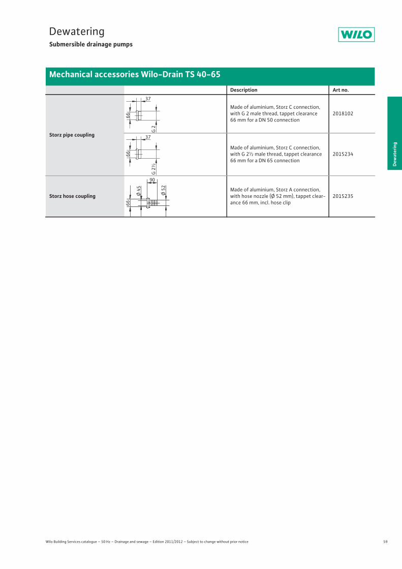
59
DewateringSubmersible drainage pumps
Wilo Building Services catalogue – 50 Hz – Drainage and sewage – Edition 2011/2012 – Subject to change without prior notice
Mechanical accessories Wilo-Drain TS 40-65
Dew
ater
ing
Storz pipe coupling
Made of aluminium, Storz C connection, with G 2 male thread, tappet clearance 66 mm for a DN 50 connection
2018102
Made of aluminium, Storz C connection, with G 2½ male thread, tappet clearance 66 mm for a DN 65 connection
2015234
Storz hose couplingMade of aluminium, Storz A connection, with hose nozzle (Ø 52 mm), tappet clear-ance 66 mm, incl. hose clip
2015235
Description Art no.
G 2
37
66
G 2
½
37
66
90
Ø 52
66
Ø 45
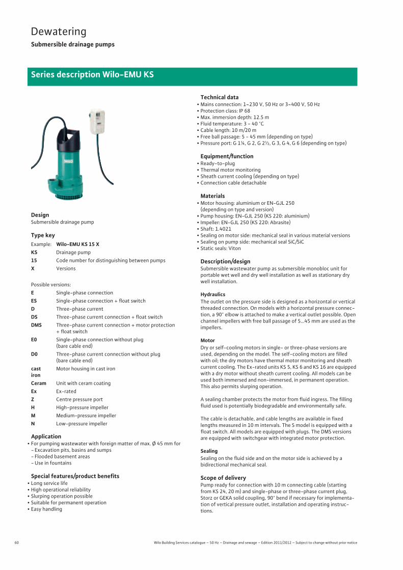
60 Wilo Building Services catalogue – 50 Hz – Drainage and sewage – Edition 2011/2012 – Subject to change without prior notice
DewateringSubmersible drainage pumps
Series description Wilo-EMU KS
DesignSubmersible drainage pump
Type key
Application• For pumping wastewater with foreign matter of max. Ø 45 mm for
- Excavation pits, basins and sumps- Flooded basement areas- Use in fountains
Special features/product benefits• Long service life• High operational reliability• Slurping operation possible• Suitable for permanent operation• Easy handling
Technical data• Mains connection: 1~230 V, 50 Hz or 3~400 V, 50 Hz• Protection class: IP 68• Max. immersion depth: 12.5 m• Fluid temperature: 3 - 40 °C• Cable length: 10 m/20 m• Free ball passage: 5 - 45 mm (depending on type)• Pressure port: G 1¼, G 2, G 2½, G 3, G 4, G 6 (depending on type)
Equipment/function• Ready-to-plug• Thermal motor monitoring• Sheath current cooling (depending on type)• Connection cable detachable
Materials• Motor housing: aluminium or EN-GJL 250
(depending on type and version)• Pump housing: EN-GJL 250 (KS 220: aluminium)• Impeller: EN-GJL 250 (KS 220: Abrasite) • Shaft: 1.4021• Sealing on motor side: mechanical seal in various material versions• Sealing on pump side: mechanical seal SiC/SiC• Static seals: Viton
Description/designSubmersible wastewater pump as submersible monobloc unit for portable wet well and dry well installation as well as stationary dry well installation.
HydraulicsThe outlet on the pressure side is designed as a horizontal or vertical threaded connection. On models with a horizontal pressure connec-tion, a 90° elbow is attached to make a vertical outlet possible. Open channel impellers with free ball passage of 5…45 mm are used as the impellers.
MotorDry or self-cooling motors in single- or three-phase versions are used, depending on the model. The self-cooling motors are filled with oil; the dry motors have thermal motor monitoring and sheath current cooling. The Ex-rated units KS 5, KS 6 and KS 16 are equipped with a dry motor without sheath current cooling. All models can be used both immersed and non-immersed, in permanent operation. This also permits slurping operation.
A sealing chamber protects the motor from fluid ingress. The filling fluid used is potentially biodegradable and environmentally safe.
The cable is detachable, and cable lengths are available in fixed lengths measured in 10 m intervals. The S model is equipped with a float switch. All models are equipped with plugs. The DMS versions are equipped with switchgear with integrated motor protection.
SealingSealing on the fluid side and on the motor side is achieved by abidirectional mechanical seal.
Scope of deliveryPump ready for connection with 10 m connecting cable (starting from KS 24, 20 m) and single-phase or three-phase current plug, Storz or GEKA solid coupling, 90° bend if necessary for implementa-tion of vertical pressure outlet, installation and operating instruc-tions.
Example: Wilo-EMU KS 15 XKS Drainage pump15 Code number for distinguishing between pumpsX Versions
Possible versions:E Single-phase connectionES Single-phase connection + float switchD Three-phase currentDS Three-phase current connection + float switchDMS Three-phase current connection + motor protection
+ float switchE0 Single-phase connection without plug
(bare cable end)D0 Three-phase current connection without plug
(bare cable end)cast iron
Motor housing in cast iron
Ceram Unit with ceram coatingEx Ex-ratedZ Centre pressure portH High-pressure impellerM Medium-pressure impellerN Low-pressure impeller
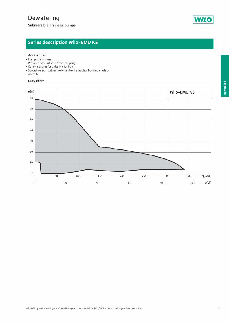
61
DewateringSubmersible drainage pumps
Dew
ater
ing
Series description Wilo-EMU KS
Wilo Building Services catalogue – 50 Hz – Drainage and sewage – Edition 2011/2012 – Subject to change without prior notice
Accessories• Flange transitions• Pressure hose kit with Storz coupling• Ceram coating for units in cast iron• Special version with impeller and/or hydraulics housing made of
Abrasite
Duty chart
Q[m³/h]0 50 100 150 200 250 300 350
Q[l/s]0 20 40 60 80 100
H[m]
0
10
20
30
40
50
60
70
Wilo-EMU KS
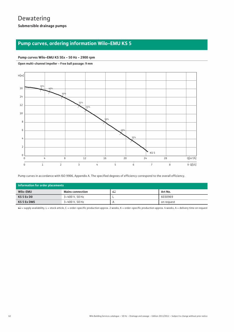
62 Wilo Building Services catalogue – 50 Hz – Drainage and sewage – Edition 2011/2012 – Subject to change without prior notice
DewateringSubmersible drainage pumps
Pump curves, ordering information Wilo-EMU KS 5
Pump curves Wilo-EMU KS 5Ex - 50 Hz - 2900 rpm
Open multi-channel impeller - Free ball passage: 9 mm
Pump curves in accordance with ISO 9906, Appendix A. The specified degrees of efficiency correspond to the overall efficiency.
Information for order placements
Wilo-EMU Mains connection � Art No.KS 5 Ex D0 3~400 V, 50 Hz L 6030969
KS 5 Ex DMS 3~400 V, 50 Hz A on request
�= supply availability, L = stock article, C = order-specific production approx. 2 weeks, K = order-specific production approx. 4 weeks, A = delivery time on request
30%
30%
40%
40%
50%
50%
55%
55%
KS 5
Q[m³/h]0 4 8 12 16 20 24 28
Q[l/s]0 1 2 3 4 5 6 7 8 9
H[m]
0
2
4
6
8
10
12
14
16
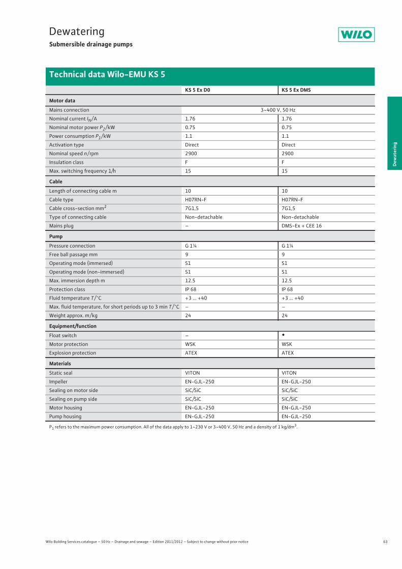
63
DewateringSubmersible drainage pumps
Wilo Building Services catalogue – 50 Hz – Drainage and sewage – Edition 2011/2012 – Subject to change without prior notice
Technical data Wilo-EMU KS 5
Dew
ater
ing
KS 5 Ex D0 KS 5 Ex DMS
Motor data
Mains connection 3~400 V, 50 Hz
Nominal current IN / A 1.76 1.76
Nominal motor power P2 / kW 0.75 0.75
Power consumption P1 / kW 1.1 1.1
Activation type Direct Direct
Nominal speed n / rpm 2900 2900
Insulation class F F
Max. switching frequency 1/h 15 15
Cable
Length of connecting cable m 10 10
Cable type H07RN-F H07RN-F
Cable cross-section mm2 7G1,5 7G1,5
Type of connecting cable Non-detachable Non-detachable
Mains plug – DMS-Ex + CEE 16
Pump
Pressure connection G 1¼ G 1¼
Free ball passage mm 9 9
Operating mode (immersed) S1 S1
Operating mode (non-immersed) S1 S1
Max. immersion depth m 12.5 12.5
Protection class IP 68 IP 68
Fluid temperature T / °C +3 ... +40 +3 ... +40
Max. fluid temperature, for short periods up to 3 min T / °C – –
Weight approx. m / kg 24 24
Equipment/function
Float switch – •Motor protection WSK WSK
Explosion protection ATEX ATEX
Materials
Static seal VITON VITON
Impeller EN-GJL-250 EN-GJL-250
Sealing on motor side SiC/SiC SiC/SiC
Sealing on pump side SiC/SiC SiC/SiC
Motor housing EN-GJL-250 EN-GJL-250
Pump housing EN-GJL-250 EN-GJL-250
P1 refers to the maximum power consumption. All of the data apply to 1~230 V or 3~400 V, 50 Hz and a density of 1 kg/dm3.
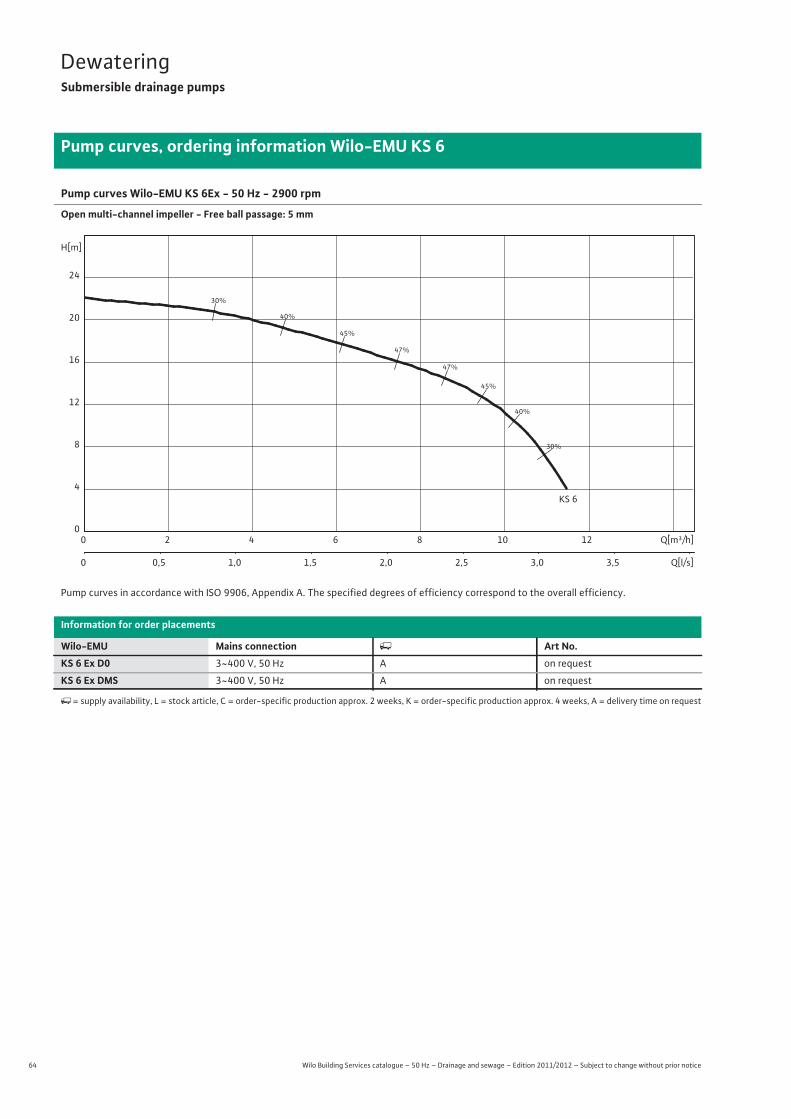
64 Wilo Building Services catalogue – 50 Hz – Drainage and sewage – Edition 2011/2012 – Subject to change without prior notice
DewateringSubmersible drainage pumps
Pump curves, ordering information Wilo-EMU KS 6
Pump curves Wilo-EMU KS 6Ex - 50 Hz - 2900 rpm
Open multi-channel impeller - Free ball passage: 5 mm
Pump curves in accordance with ISO 9906, Appendix A. The specified degrees of efficiency correspond to the overall efficiency.
Information for order placements
Wilo-EMU Mains connection � Art No.KS 6 Ex D0 3~400 V, 50 Hz A on request
KS 6 Ex DMS 3~400 V, 50 Hz A on request
� = supply availability, L = stock article, C = order-specific production approx. 2 weeks, K = order-specific production approx. 4 weeks, A = delivery time on request
30%
30%
40%
40%
45%
45%
47%
47%
KS 6
Q[m³/h]0 2 4 6 8 10 12
Q[l/s]0 0,5 1,0 1,5 2,0 2,5 3,0 3,5
H[m]
0
4
8
12
16
20
24

65
DewateringSubmersible drainage pumps
Wilo Building Services catalogue – 50 Hz – Drainage and sewage – Edition 2011/2012 – Subject to change without prior notice
Technical data Wilo-EMU KS 6
Dew
ater
ing
KS 6 Ex D0 KS 6 Ex DMS
Motor data
Mains connection 3~400 V, 50 Hz
Nominal current IN / A 1.76 1.76
Nominal motor power P2 / kW 0.75 0.75
Power consumption P1 / kW 1.1 1.1
Activation type Direct Direct
Nominal speed n / rpm 2900 2900
Insulation class F F
Max. switching frequency 1/h 15 15
Cable
Length of connecting cable m 10 10
Cable type H07RN-F H07RN-F
Cable cross-section mm2 7G1,5 7G1,5
Type of connecting cable Non-detachable Non-detachable
Mains plug – DMS-Ex + CEE 16
Pump
Pressure connection G 1¼ G 1¼
Free ball passage mm 5 5
Operating mode (immersed) S1 S1
Operating mode (non-immersed) S1 S1
Max. immersion depth m 12.5 12.5
Protection class IP 68 IP 68
Fluid temperature T / °C +3 ... +40 +3 ... +40
Max. fluid temperature, for short periods up to 3 min T / °C – –
Weight approx. m / kg 24 24
Equipment/function
Float switch – •Motor protection WSK WSK
Explosion protection ATEX ATEX
Materials
Static seal VITON VITON
Impeller EN-GJL-250 EN-GJL-250
Sealing on motor side SiC/SiC SiC/SiC
Sealing on pump side SiC/SiC SiC/SiC
Motor housing EN-GJL-250 EN-GJL-250
Pump housing EN-GJL-250 EN-GJL-250
P1 refers to the maximum power consumption. All of the data apply to 1~230 V or 3~400 V, 50 Hz and a density of 1 kg/dm3.
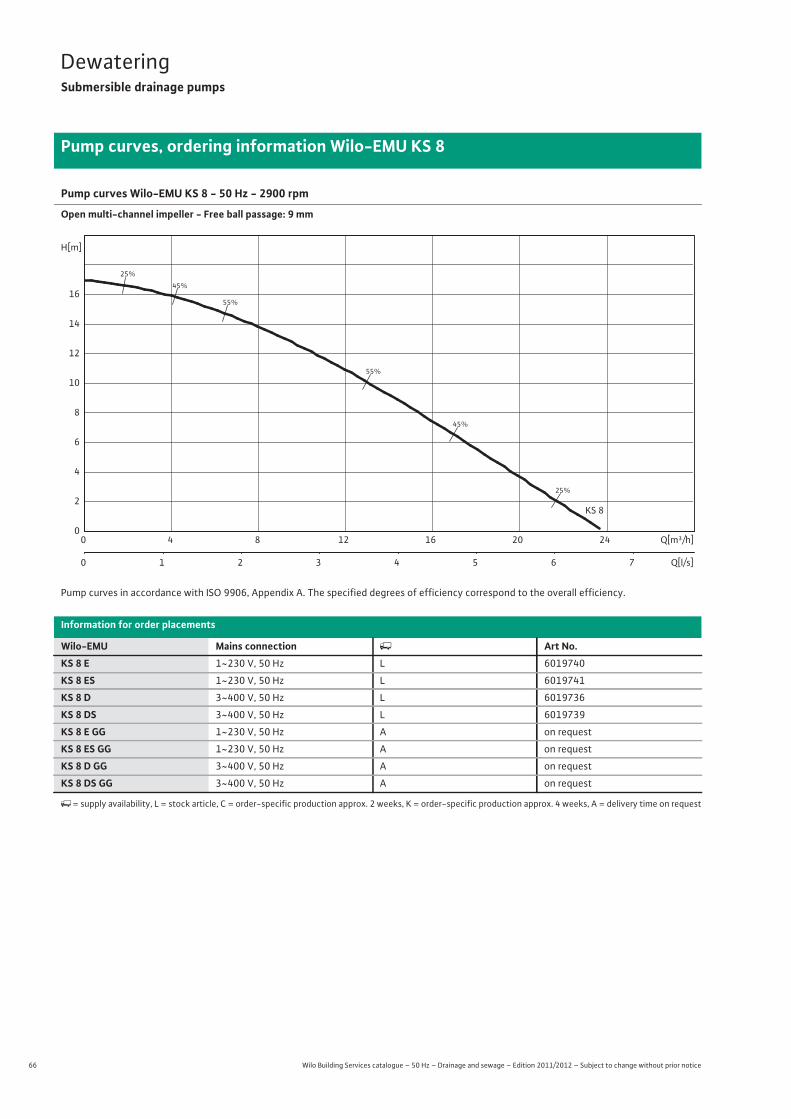
66 Wilo Building Services catalogue – 50 Hz – Drainage and sewage – Edition 2011/2012 – Subject to change without prior notice
DewateringSubmersible drainage pumps
Pump curves, ordering information Wilo-EMU KS 8
Pump curves Wilo-EMU KS 8 - 50 Hz - 2900 rpm
Open multi-channel impeller - Free ball passage: 9 mm
Pump curves in accordance with ISO 9906, Appendix A. The specified degrees of efficiency correspond to the overall efficiency.
Information for order placements
Wilo-EMU Mains connection � Art No.KS 8 E 1~230 V, 50 Hz L 6019740
KS 8 ES 1~230 V, 50 Hz L 6019741
KS 8 D 3~400 V, 50 Hz L 6019736
KS 8 DS 3~400 V, 50 Hz L 6019739
KS 8 E GG 1~230 V, 50 Hz A on request
KS 8 ES GG 1~230 V, 50 Hz A on request
KS 8 D GG 3~400 V, 50 Hz A on request
KS 8 DS GG 3~400 V, 50 Hz A on request
�= supply availability, L = stock article, C = order-specific production approx. 2 weeks, K = order-specific production approx. 4 weeks, A = delivery time on request
25%
25%
45%
45%
55%
55%
KS 8
Q[m³/h]0 4 8 12 16 20 24
Q[l/s]0 1 2 3 4 5 6 7
H[m]
0
2
4
6
8
10
12
14
16

67
DewateringSubmersible drainage pumps
Wilo Building Services catalogue – 50 Hz – Drainage and sewage – Edition 2011/2012 – Subject to change without prior notice
Technical data Wilo-EMU KS 8
Dew
ater
ing
KS 8 E KS 8 ES KS 8 D KS 8 DS
Motor data
Mains connection 1~230 V, 50 Hz 3~400 V, 50 Hz
Nominal current IN / A 5.70 5.70 1.90 1.90
Nominal motor power P2 / kW 0.75 0.75 0.75 0.75
Power consumption P1 / kW 1.1 1.1 1.1 1.1
Activation type Direct Direct Direct Direct
Nominal speed n / rpm 2900 2900 2900 2900
Insulation class F F F F
Max. switching frequency 1/h 15 15 15 15
Cable
Length of connecting cable m 10 10 10 10
Cable type H07RN-F H07RN-F H07RN-F H07RN-F
Cable cross-section mm2 4G1,5 4G1,5 4G1,5 4G1,5
Type of connecting cable Detachable Detachable Detachable Detachable
Mains plug SMP 6M SMP 6MA CEE M 16 W CEE M 16 WDSHA
Pump
Pressure connection G 1¼ G 1¼ G 1¼ G 1¼
Free ball passage mm 9 9 9 9
Operating mode (immersed) S1 S1 S1 S1
Operating mode (non-immersed) S1 S1 S1 S1
Max. immersion depth m 12.5 12.5 12.5 12.5
Protection class IP 68 IP 68 IP 68 IP 68
Fluid temperature T / °C +3 ... +40 +3 ... +40 +3 ... +40 +3 ... +40
Max. fluid temperature, for short periods up to 3 min T / °C – – – –
Weight approx. m / kg 21 21 21 21
Equipment/function
Float switch – • – •Motor protection – – – –
Explosion protection – – – –
Materials
Static seal VITON VITON VITON VITON
Impeller EN-GJL-250 EN-GJL-250 EN-GJL-250 EN-GJL-250
Sealing on motor side C/Al-oxides C/Al-oxides C/Al-oxides C/Al-oxides
Sealing on pump side SiC/SiC SiC/SiC SiC/SiC SiC/SiC
Motor housing G-Al Si12 G-Al Si12 G-Al Si12 G-Al Si12
Pump housing EN-GJL-250 EN-GJL-250 EN-GJL-250 EN-GJL-250
P1 refers to the maximum power consumption. All of the data apply to 1~230 V or 3~400 V, 50 Hz and a density of 1 kg/dm3.

68 Wilo Building Services catalogue – 50 Hz – Drainage and sewage – Edition 2011/2012 – Subject to change without prior notice
DewateringSubmersible drainage pumps
Technical data Wilo-EMU KS 8
KS 8 E GG KS 8 ES GG KS 8 D GG KS 8 DS GG
Motor data
Mains connection 1~230 V, 50 Hz 3~400 V, 50 Hz
Nominal current IN / A 5.70 5.70 1.90 1.90
Nominal motor power P2 / kW 0.75 0.75 0.75 0.75
Power consumption P1 / kW 1.1 1.1 1.1 1.1
Activation type Direct Direct Direct Direct
Nominal speed n / rpm 2900 2900 2900 2900
Insulation class F F F F
Max. switching frequency 1/h 15 15 15 15
Cable
Length of connecting cable m 10 10 10 10
Cable type H07RN-F H07RN-F H07RN-F H07RN-F
Cable cross-section mm2 4G1,5 4G1,5 4G1,5 4G1,5
Type of connecting cable Detachable Detachable Detachable Detachable
Mains plug SMP 6M SMP 6MA CEE M 16 W CEE M 16 WDSHA
Pump
Pressure connection G 1¼ G 1¼ G 1¼ G 1¼
Free ball passage mm 9 9 9 9
Operating mode (immersed) S1 S1 S1 S1
Operating mode (non-immersed) S1 S1 S1 S1
Max. immersion depth m 12.5 12.5 12.5 12.5
Protection class IP 68 IP 68 IP 68 IP 68
Fluid temperature T / °C +3 ... +40 +3 ... +40 +3 ... +40 +3 ... +40
Max. fluid temperature, for short periods up to 3 min T / °C – – – –
Weight approx. m / kg 25 25 25 25
Equipment/function
Float switch – • – •Motor protection – – – –
Explosion protection – – – –
Materials
Static seal VITON VITON VITON VITON
Impeller EN-GJL-250 EN-GJL-250 EN-GJL-250 EN-GJL-250,
Sealing on motor side C/Al-oxides C/Al-oxides C/Al-oxides C/Al-oxides
Sealing on pump side SiC/SiC SiC/SiC SiC/SiC SiC/SiC
Motor housing EN-GJL-250 EN-GJL-250 EN-GJL-250 EN-GJL-250
Pump housing EN-GJL-250 EN-GJL-250 EN-GJL-250 EN-GJL-250
P1 refers to the maximum power consumption. All of the data apply to 1~230 V or 3~400 V, 50 Hz and a density of 1 kg/dm3.
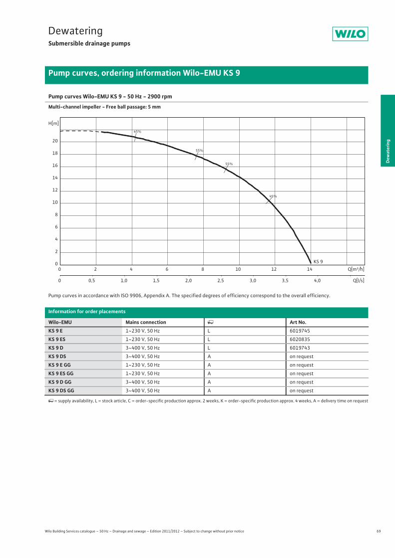
69
DewateringSubmersible drainage pumps
Dew
ater
ing
Pump curves, ordering information Wilo-EMU KS 9
Wilo Building Services catalogue – 50 Hz – Drainage and sewage – Edition 2011/2012 – Subject to change without prior notice
Pump curves Wilo-EMU KS 9 - 50 Hz - 2900 rpm
Multi-channel impeller - Free ball passage: 5 mm
Pump curves in accordance with ISO 9906, Appendix A. The specified degrees of efficiency correspond to the overall efficiency.
Information for order placements
Wilo-EMU Mains connection � Art No.KS 9 E 1~230 V, 50 Hz L 6019745
KS 9 ES 1~230 V, 50 Hz L 6020835
KS 9 D 3~400 V, 50 Hz L 6019743
KS 9 DS 3~400 V, 50 Hz A on request
KS 9 E GG 1~230 V, 50 Hz A on request
KS 9 ES GG 1~230 V, 50 Hz A on request
KS 9 D GG 3~400 V, 50 Hz A on request
KS 9 DS GG 3~400 V, 50 Hz A on request
�= supply availability, L = stock article, C = order-specific production approx. 2 weeks, K = order-specific production approx. 4 weeks, A = delivery time on request
45%
45%
55%
55%
KS 9Q[m³/h]0 2 4 6 8 10 12 14
Q[l/s]0 0,5 1,0 1,5 2,0 2,5 3,0 3,5 4,0
H[m]
0
2
4
6
8
10
12
14
16
18
20

70 Wilo Building Services catalogue – 50 Hz – Drainage and sewage – Edition 2011/2012 – Subject to change without prior notice
DewateringSubmersible drainage pumps
Technical data Wilo-EMU KS 9
KS 9 E KS 9 ES KS 9 D KS 9 DS
Motor data
Mains connection 1~230 V, 50 Hz 3~400 V, 50 Hz
Nominal current IN / A 5.70 5.70 1.90 1.90
Nominal motor power P2 / kW 0.75 0.75 0.75 0.75
Power consumption P1 / kW 1.1 1.1 1.1 1.1
Activation type Direct Direct Direct Direct
Nominal speed n / rpm 2900 2900 2900 2900
Insulation class F F F F
Max. switching frequency 1/h 15 15 15 15
Cable
Length of connecting cable m 10 10 10 10
Cable type H07RN-F H07RN-F H07RN-F H07RN-F
Cable cross-section mm2 4G1,5 4G1,5 4G1,5 4G1,5
Type of connecting cable Detachable Detachable Detachable Detachable
Mains plug SMP 6M SMP 6MA CEE M 16 W CEE M 16 WDSHA
Pump
Pressure connection G 1¼ G 1¼ G 1¼ G 1¼
Free ball passage mm 5 5 5 5
Operating mode (immersed) S1 S1 S1 S1
Operating mode (non-immersed) S1 S1 S1 S1
Max. immersion depth m 12.5 12.5 12.5 12.5
Protection class IP 68 IP 68 IP 68 IP 68
Fluid temperature T / °C +3 ... +40 +3 ... +40 +3 ... +40 +3 ... +40
Max. fluid temperature, for short periods up to 3 min T / °C – – – –
Weight approx. m / kg 21 21 21 21
Equipment/function
Float switch – • – •Motor protection – – – –
Explosion protection – – – –
Materials
Static seal VITON VITON VITON VITON
Impeller EN-GJL-250 EN-GJL-250 EN-GJL-250 EN-GJL-250
Sealing on motor side C/Al-oxides C/Al-oxides C/Al-oxides C/Al-oxides
Sealing on pump side SiC/SiC SiC/SiC SiC/SiC SiC/SiC
Motor housing G-Al Si12 G-Al Si12 G-Al Si12 G-Al Si12
Pump housing EN-GJL-250 EN-GJL-250 EN-GJL-250 EN-GJL-250
P1 refers to the maximum power consumption. All of the data apply to 1~230 V or 3~400 V, 50 Hz and a density of 1 kg/dm3.

71
DewateringSubmersible drainage pumps
Wilo Building Services catalogue – 50 Hz – Drainage and sewage – Edition 2011/2012 – Subject to change without prior notice
Technical data Wilo-EMU KS 9
Dew
ater
ing
KS 9 E GG KS 9 ES GG KS 9 D GG KS 9 DS GG
Motor data
Mains connection 1~230 V, 50 Hz 3~400 V, 50 Hz
Nominal current IN / A 5.70 5.70 1.90 1.90
Nominal motor power P2 / kW 0.75 0.75 0.75 0.75
Power consumption P1 / kW 1.1 1.1 1.1 1.1
Activation type Direct Direct Direct Direct
Nominal speed n / rpm 2900 2900 2900 2900
Insulation class F F F F
Max. switching frequency 1/h 15 15 15 15
Cable
Length of connecting cable m 10 10 10 10
Cable type H07RN-F H07RN-F H07RN-F H07RN-F
Cable cross-section mm2 4G1,5 4G1,5 4G1,5 4G1,5
Type of connecting cable Detachable Detachable Detachable Detachable
Mains plug SMP 6M SMP 6MA CEE M 16 W CEE M 16 WDSHA
Pump
Pressure connection G 1¼ G 1¼ G 1¼ G 1¼
Free ball passage mm 5 5 5 5
Operating mode (immersed) S1 S1 S1 S1
Operating mode (non-immersed) S1 S1 S1 S1
Max. immersion depth m 12.5 12.5 12.5 12.5
Protection class IP 68 IP 68 IP 68 IP 68
Fluid temperature T / °C +3 ... +40 +3 ... +40 +3 ... +40 +3 ... +40
Max. fluid temperature, for short periods up to 3 min T / °C – – – –
Weight approx. m / kg 25 25 25 25
Equipment/function
Float switch – • – •Motor protection – – – –
Explosion protection – – – –
Materials
Static seal VITON VITON VITON VITON
Impeller EN-GJL-250 EN-GJL-250 EN-GJL-250 EN-GJL-250
Sealing on motor side C/Al-oxides C/Al-oxides C/Al-oxides C/Al-oxides
Sealing on pump side SiC/SiC SiC/SiC SiC/SiC SiC/SiC
Motor housing EN-GJL-250 EN-GJL-250 EN-GJL-250 EN-GJL-250
Pump housing EN-GJL-250 EN-GJL-250 EN-GJL-250 EN-GJL-250
P1 refers to the maximum power consumption. All of the data apply to 1~230 V or 3~400 V, 50 Hz and a density of 1 kg/dm3.
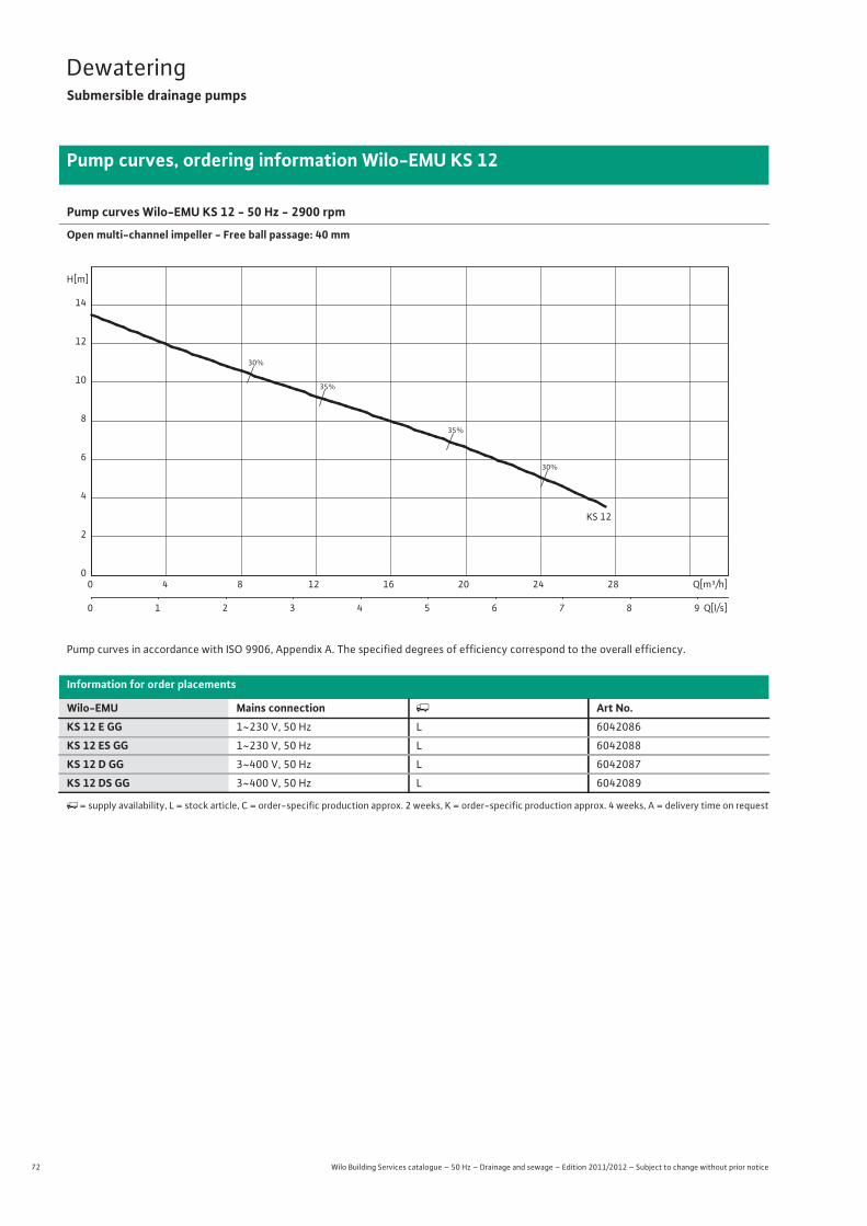
72 Wilo Building Services catalogue – 50 Hz – Drainage and sewage – Edition 2011/2012 – Subject to change without prior notice
DewateringSubmersible drainage pumps
Pump curves, ordering information Wilo-EMU KS 12
Pump curves Wilo-EMU KS 12 - 50 Hz - 2900 rpm
Open multi-channel impeller - Free ball passage: 40 mm
Pump curves in accordance with ISO 9906, Appendix A. The specified degrees of efficiency correspond to the overall efficiency.
Information for order placements
Wilo-EMU Mains connection � Art No.KS 12 E GG 1~230 V, 50 Hz L 6042086
KS 12 ES GG 1~230 V, 50 Hz L 6042088
KS 12 D GG 3~400 V, 50 Hz L 6042087
KS 12 DS GG 3~400 V, 50 Hz L 6042089
�= supply availability, L = stock article, C = order-specific production approx. 2 weeks, K = order-specific production approx. 4 weeks, A = delivery time on request
30%
30%
35%
35%
KS 12
Q[m³/h]0 4 8 12 16 20 24 28
Q[l/s]0 1 2 3 4 5 6 7 8 9
H[m]
0
2
4
6
8
10
12
14

73
DewateringSubmersible drainage pumps
Wilo Building Services catalogue – 50 Hz – Drainage and sewage – Edition 2011/2012 – Subject to change without prior notice
Technical data Wilo-EMU KS 12
Dew
ater
ing
KS 12 E GG KS 12 ES GG KS 12 D GG KS 12 DS GG
Motor data
Mains connection 1~230 V, 50 Hz 3~400 V, 50 Hz
Nominal current IN / A 9.40 9.40 3.15 3.15
Nominal motor power P2 / kW 1.3 1.3 1.3 1.3
Power consumption P1 / kW 1.9 1.9 1.9 1.9
Activation type Direct Direct Direct Direct
Nominal speed n / rpm 2900 2900 2900 2900
Insulation class F F F F
Max. switching frequency 1/h 15 15 15 15
Cable
Length of connecting cable m 10 10 10 10
Cable type H07RN-F H07RN-F H07RN-F H07RN-F
Cable cross-section mm2 4G1,5 4G1,5 4G1,5 4G1,5
Type of connecting cable Detachable Detachable Detachable Detachable
Mains plug SMP 10M SMP 10MA CEE M 16 W CEE M 16 WDSHA
Pump
Pressure connection G 2 G 2 G 2 G 2
Free ball passage mm 40 40 40 40
Operating mode (immersed) S1 S1 S1 S1
Operating mode (non-immersed) S1 S1 S1 S1
Max. immersion depth m 12.5 12.5 12.5 12.5
Protection class IP 68 IP 68 IP 68 IP 68
Fluid temperature T / °C +3 ... +40 +3 ... +40 +3 ... +40 +3 ... +40
Max. fluid temperature, for short periods up to 3 min T / °C – – – –
Weight approx. m / kg 28 28 28 28
Equipment/function
Float switch – • – •Motor protection – – – –
Explosion protection – – – –
Materials
Static seal VITON VITON VITON VITON
Impeller EN-GJL-250 EN-GJL-250 EN-GJL-250 EN-GJL-250
Sealing on motor side C/Al-oxides C/Al-oxides C/Al-oxides C/Al-oxides
Sealing on pump side SiC/SiC SiC/SiC SiC/SiC SiC/SiC
Motor housing EN-GJL-250 EN-GJL-250 EN-GJL-250 EN-GJL-250
Pump housing EN-GJL-250 EN-GJL-250 EN-GJL-250 EN-GJL-250
P1 refers to the maximum power consumption. All of the data apply to 1~230 V or 3~400 V, 50 Hz and a density of 1 kg/dm3.
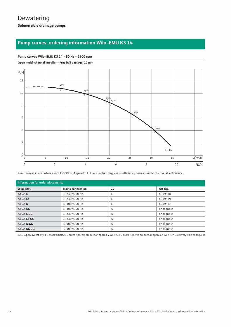
74 Wilo Building Services catalogue – 50 Hz – Drainage and sewage – Edition 2011/2012 – Subject to change without prior notice
DewateringSubmersible drainage pumps
Pump curves, ordering information Wilo-EMU KS 14
Pump curves Wilo-EMU KS 14 - 50 Hz - 2900 rpm
Open multi-channel impeller - Free ball passage: 10 mm
Pump curves in accordance with ISO 9906, Appendix A. The specified degrees of efficiency correspond to the overall efficiency.
Information for order placements
Wilo-EMU Mains connection � Art No.KS 14 E 1~230 V, 50 Hz L 6019448
KS 14 ES 1~230 V, 50 Hz L 6019449
KS 14 D 3~400 V, 50 Hz L 6019447
KS 14 DS 3~400 V, 50 Hz A on request
KS 14 E GG 1~230 V, 50 Hz A on request
KS 14 ES GG 1~230 V, 50 Hz A on request
KS 14 D GG 3~400 V, 50 Hz A on request
KS 14 DS GG 3~400 V, 50 Hz A on request
�= supply availability, L = stock article, C = order-specific production approx. 2 weeks, K = order-specific production approx. 4 weeks, A = delivery time on request
45%
45%
60%
60%
65%65%
KS 14
Q[m³/h]0 5 10 15 20 25 30 35
Q[l/s]0 2 4 6 8 10
H[m]
0
2
4
6
8
10
12

75
DewateringSubmersible drainage pumps
Wilo Building Services catalogue – 50 Hz – Drainage and sewage – Edition 2011/2012 – Subject to change without prior notice
Technical data Wilo-EMU KS 14
Dew
ater
ing
KS 14 E KS 14 ES KS 14 D KS 14 DS
Motor data
Mains connection 1~230 V, 50 Hz 3~400 V, 50 Hz
Nominal current IN / A 5.70 5.70 1.90 1.90
Nominal motor power P2 / kW 0.75 0.75 0.75 0.75
Power consumption P1 / kW 1.1 1.1 1.1 1.1
Activation type Direct Direct Direct Direct
Nominal speed n / rpm 2900 2900 2900 2900
Insulation class F F F F
Max. switching frequency 1/h 15 15 15 15
Cable
Length of connecting cable m 10 10 10 10
Cable type H07RN-F H07RN-F H07RN-F H07RN-F
Cable cross-section mm2 4G1,5 4G1,5 4G1,5 4G1,5
Type of connecting cable Detachable Detachable Detachable Detachable
Mains plug SMP 6M SMP 6MA CEE M 16 W CEE M 16 WDSHA
Pump
Pressure connection G 2 G 2 G 2 G 2
Free ball passage mm 10 10 10 10
Operating mode (immersed) S1 S1 S1 S1
Operating mode (non-immersed) S1 S1 S1 S1
Max. immersion depth m 12.5 12.5 12.5 12.5
Protection class IP 68 IP 68 IP 68 IP 68
Fluid temperature T / °C +3 ... +40 +3 ... +40 +3 ... +40 +3 ... +40
Max. fluid temperature, for short periods up to 3 min T / °C – – – –
Weight approx. m / kg 21 21 21 21
Equipment/function
Float switch – • – •Motor protection – – – –
Explosion protection – – – –
Materials
Static seal VITON VITON VITON VITON
Impeller EN-GJL-250 EN-GJL-250 EN-GJL-250 EN-GJL-250
Sealing on motor side C/Al-oxides C/Al-oxides C/Al-oxides C/Al-oxides
Sealing on pump side SiC/SiC SiC/SiC SiC/SiC SiC/SiC
Motor housing G-Al Si12 G-Al Si12 G-Al Si12 G-Al Si12
Pump housing EN-GJL-250 EN-GJL-250 EN-GJL-250 EN-GJL-250
P1 refers to the maximum power consumption. All of the data apply to 1~230 V or 3~400 V, 50 Hz and a density of 1 kg/dm3.
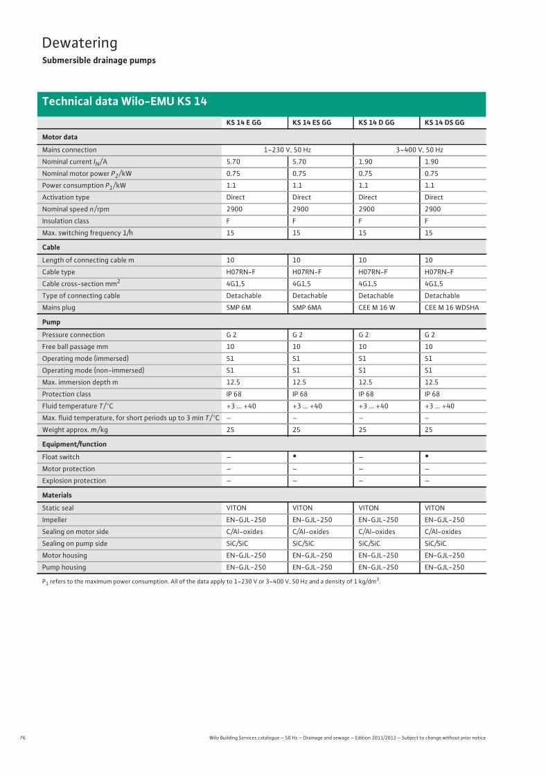
76 Wilo Building Services catalogue – 50 Hz – Drainage and sewage – Edition 2011/2012 – Subject to change without prior notice
DewateringSubmersible drainage pumps
Technical data Wilo-EMU KS 14
KS 14 E GG KS 14 ES GG KS 14 D GG KS 14 DS GG
Motor data
Mains connection 1~230 V, 50 Hz 3~400 V, 50 Hz
Nominal current IN / A 5.70 5.70 1.90 1.90
Nominal motor power P2 / kW 0.75 0.75 0.75 0.75
Power consumption P1 / kW 1.1 1.1 1.1 1.1
Activation type Direct Direct Direct Direct
Nominal speed n / rpm 2900 2900 2900 2900
Insulation class F F F F
Max. switching frequency 1/h 15 15 15 15
Cable
Length of connecting cable m 10 10 10 10
Cable type H07RN-F H07RN-F H07RN-F H07RN-F
Cable cross-section mm2 4G1,5 4G1,5 4G1,5 4G1,5
Type of connecting cable Detachable Detachable Detachable Detachable
Mains plug SMP 6M SMP 6MA CEE M 16 W CEE M 16 WDSHA
Pump
Pressure connection G 2 G 2 G 2 G 2
Free ball passage mm 10 10 10 10
Operating mode (immersed) S1 S1 S1 S1
Operating mode (non-immersed) S1 S1 S1 S1
Max. immersion depth m 12.5 12.5 12.5 12.5
Protection class IP 68 IP 68 IP 68 IP 68
Fluid temperature T / °C +3 ... +40 +3 ... +40 +3 ... +40 +3 ... +40
Max. fluid temperature, for short periods up to 3 min T / °C – – – –
Weight approx. m / kg 25 25 25 25
Equipment/function
Float switch – • – •Motor protection – – – –
Explosion protection – – – –
Materials
Static seal VITON VITON VITON VITON
Impeller EN-GJL-250 EN-GJL-250 EN-GJL-250 EN-GJL-250
Sealing on motor side C/Al-oxides C/Al-oxides C/Al-oxides C/Al-oxides
Sealing on pump side SiC/SiC SiC/SiC SiC/SiC SiC/SiC
Motor housing EN-GJL-250 EN-GJL-250 EN-GJL-250 EN-GJL-250
Pump housing EN-GJL-250 EN-GJL-250 EN-GJL-250 EN-GJL-250
P1 refers to the maximum power consumption. All of the data apply to 1~230 V or 3~400 V, 50 Hz and a density of 1 kg/dm3.
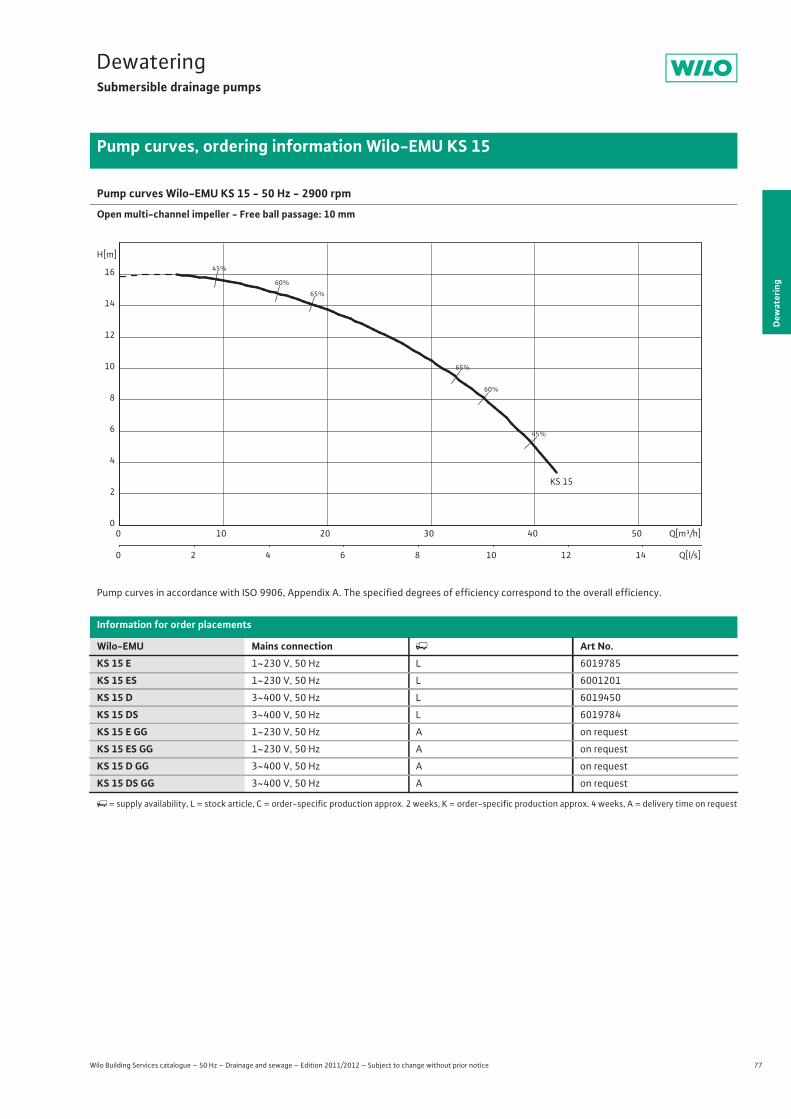
77
DewateringSubmersible drainage pumps
Dew
ater
ing
Pump curves, ordering information Wilo-EMU KS 15
Wilo Building Services catalogue – 50 Hz – Drainage and sewage – Edition 2011/2012 – Subject to change without prior notice
Pump curves Wilo-EMU KS 15 - 50 Hz - 2900 rpm
Open multi-channel impeller - Free ball passage: 10 mm
Pump curves in accordance with ISO 9906, Appendix A. The specified degrees of efficiency correspond to the overall efficiency.
Information for order placements
Wilo-EMU Mains connection � Art No.KS 15 E 1~230 V, 50 Hz L 6019785
KS 15 ES 1~230 V, 50 Hz L 6001201
KS 15 D 3~400 V, 50 Hz L 6019450
KS 15 DS 3~400 V, 50 Hz L 6019784
KS 15 E GG 1~230 V, 50 Hz A on request
KS 15 ES GG 1~230 V, 50 Hz A on request
KS 15 D GG 3~400 V, 50 Hz A on request
KS 15 DS GG 3~400 V, 50 Hz A on request
�= supply availability, L = stock article, C = order-specific production approx. 2 weeks, K = order-specific production approx. 4 weeks, A = delivery time on request
45%
45%
60%
60%
65%
65%
KS 15
Q[m³/h]0 10 20 30 40 50
Q[l/s]0 2 4 6 8 10 12 14
H[m]
0
2
4
6
8
10
12
14
16

78 Wilo Building Services catalogue – 50 Hz – Drainage and sewage – Edition 2011/2012 – Subject to change without prior notice
DewateringSubmersible drainage pumps
Technical data Wilo-EMU KS 15
KS 15 E KS 15 ES KS 15 D KS 15 DS
Motor data
Mains connection 1~230 V, 50 Hz 3~400 V, 50 Hz
Nominal current IN / A 9.40 9.40 3.20 3.20
Nominal motor power P2 / kW 1.3 1.3 1.3 1.3
Power consumption P1 / kW 1.9 1.9 1.9 1.9
Activation type Direct Direct Direct Direct
Nominal speed n / rpm 2900 2900 2900 2900
Insulation class F F F F
Max. switching frequency 1/h 15 15 15 15
Cable
Length of connecting cable m 10 10 10 10
Cable type H07RN-F H07RN-F H07RN-F H07RN-F
Cable cross-section mm2 4G1,5 4G1,5 4G1,5 4G1,5
Type of connecting cable Detachable Detachable Detachable Detachable
Mains plug SMP 10M SMP 10MA CEE M 16 W CEE M 16 WDSHA
Pump
Pressure connection G 2 G 2 G 2 G 2
Free ball passage mm 10 10 10 10
Operating mode (immersed) S1 S1 S1 S1
Operating mode (non-immersed) S1 S1 S1 S1
Max. immersion depth m 12.5 12.5 12.5 12.5
Protection class IP 68 IP 68 IP 68 IP 68
Fluid temperature T / °C +3 ... +40 +3 ... +40 +3 ... +40 +3 ... +40
Max. fluid temperature, for short periods up to 3 min T / °C – – – –
Weight approx. m / kg 26 26 26 26
Equipment/function
Float switch – • – •Motor protection – – – –
Explosion protection – – – –
Materials
Static seal VITON VITON VITON VITON
Impeller EN-GJL-250 EN-GJL-250 EN-GJL-250 EN-GJL-250
Sealing on motor side C/Al-oxides C/Al-oxides C/Al-oxides C/Al-oxides
Sealing on pump side SiC/SiC SiC/SiC SiC/SiC SiC/SiC
Motor housing G-Al Si12 G-Al Si12 G-Al Si12 G-Al Si12
Pump housing EN-GJL-250 EN-GJL-250 EN-GJL-250 EN-GJL-250
P1 refers to the maximum power consumption. All of the data apply to 1~230 V or 3~400 V, 50 Hz and a density of 1 kg/dm3.

79
DewateringSubmersible drainage pumps
Wilo Building Services catalogue – 50 Hz – Drainage and sewage – Edition 2011/2012 – Subject to change without prior notice
Technical data Wilo-EMU KS 15
Dew
ater
ing
KS 15 E GG KS 15 ES GG KS 15 DS GG KS 15 D GG
Motor data
Mains connection 1~230 V, 50 Hz 3~400 V, 50 Hz
Nominal current IN / A 9.40 9.40 3.20 3.20
Nominal motor power P2 / kW 1.3 1.3 1.3 1.3
Power consumption P1 / kW 1.9 1.9 1.9 1.9
Activation type Direct Direct Direct Direct
Nominal speed n / rpm 2900 2900 2900 2900
Insulation class F F F F
Max. switching frequency 1/h 15 15 15 15
Cable
Length of connecting cable m 10 10 10 10
Cable type H07RN-F H07RN-F H07RN-F H07RN-F
Cable cross-section mm2 4G1,5 4G1,5 4G1,5 4G1,5
Type of connecting cable Detachable Detachable Detachable Detachable
Mains plug SMP 10M SMP 10MA CEE M 16 WDSHA CEE M 16 W
Pump
Pressure connection G 2 G 2 G 2 G 2
Free ball passage mm 10 10 10 10
Operating mode (immersed) S1 S1 S1 S1
Operating mode (non-immersed) S1 S1 S1 S1
Max. immersion depth m 12.5 12.5 12.5 12.5
Protection class IP 68 IP 68 IP 68 IP 68
Fluid temperature T / °C +3 ... +40 +3 ... +40 +3 ... +40 +3 ... +40
Max. fluid temperature, for short periods up to 3 min T / °C – – – –
Weight approx. m / kg 30 30 30 30
Equipment/function
Float switch – • • –
Motor protection – – – –
Explosion protection – – – –
Materials
Static seal VITON VITON VITON VITON
Impeller EN-GJL-250 EN-GJL-250 EN-GJL-250 EN-GJL-250
Sealing on motor side C/Al-oxides C/Al-oxides C/Al-oxides C/Al-oxides
Sealing on pump side SiC/SiC SiC/SiC SiC/SiC SiC/SiC
Motor housing EN-GJL-250 EN-GJL-250 EN-GJL-250 EN-GJL-250
Pump housing EN-GJL-250 EN-GJL-250 EN-GJL-250 EN-GJL-250
P1 refers to the maximum power consumption. All of the data apply to 1~230 V or 3~400 V, 50 Hz and a density of 1 kg/dm3.

80 Wilo Building Services catalogue – 50 Hz – Drainage and sewage – Edition 2011/2012 – Subject to change without prior notice
DewateringSubmersible drainage pumps
Pump curves, ordering information Wilo-EMU KS 16
Pump curves Wilo-EMU KS 16Ex - 50 Hz - 2900 rpm
Open multi-channel impeller - Free ball passage: 12 mm
Pump curves in accordance with ISO 9906, Appendix A. The specified degrees of efficiency correspond to the overall efficiency.
Information for order placements
Wilo-EMU Mains connection � Art No.KS 16 Ex D0 3~400 V, 50 Hz A on request
KS 16 Ex DMS-Ex 3~400 V, 50 Hz A on request
�= supply availability, L = stock article, C = order-specific production approx. 2 weeks, K = order-specific production approx. 4 weeks, A = delivery time on request
25%
25%
45%
45%
60%
60%
KS 16
Q[m³/h]0 10 20 30 40 50 60
Q[l/s]0 2 4 6 8 10 12 14 16 18
H[m]
0
2
4
6
8
10
12
14
16
18

81
DewateringSubmersible drainage pumps
Wilo Building Services catalogue – 50 Hz – Drainage and sewage – Edition 2011/2012 – Subject to change without prior notice
Technical data Wilo-EMU KS 16
Dew
ater
ing
KS 16 Ex D0 KS 16 Ex DMS-Ex
Motor data
Mains connection 3~400 V, 50 Hz
Nominal current IN / A 4.50 4.50
Nominal motor power P2 / kW 2 2
Power consumption P1 / kW 2.6 2.6
Activation type Direct Direct
Nominal speed n / rpm 2900 2900
Insulation class F F
Max. switching frequency 1/h 15 15
Cable
Length of connecting cable m 10 10
Cable type H07RN-F H07RN-F
Cable cross-section mm2 7G1,5 7G1,5
Type of connecting cable Non-detachable Non-detachable
Mains plug – DMS-Ex + CEE 16
Pump
Pressure connection G 2 G 2
Free ball passage mm 12 12
Operating mode (immersed) S1 S1
Operating mode (non-immersed) S1 S1
Max. immersion depth m 12.5 12.5
Protection class IP 68 IP 68
Fluid temperature T / °C +3 ... +40 +3 ... +40
Max. fluid temperature, for short periods up to 3 min T / °C – –
Weight approx. m / kg 30 30
Equipment/function
Float switch – •Motor protection WSK WSK
Explosion protection ATEX ATEX
Materials
Static seal VITON VITON
Impeller EN-GJL-250 EN-GJL-250
Sealing on motor side SiC/SiC SiC/SiC
Sealing on pump side SiC/SiC SiC/SiC
Motor housing EN-GJL-250 EN-GJL-250
Pump housing EN-GJL-250 EN-GJL-250
P1 refers to the maximum power consumption. All of the data apply to 1~230 V or 3~400 V, 50 Hz and a density of 1 kg/dm3.

82 Wilo Building Services catalogue – 50 Hz – Drainage and sewage – Edition 2011/2012 – Subject to change without prior notice
DewateringSubmersible drainage pumps
Pump curves, ordering information Wilo-EMU KS 20
Pump curves Wilo-EMU KS 20 - 50 Hz - 2900 rpm
Open multi-channel impeller - Free ball passage: 45 mm
Pump curves in accordance with ISO 9906, Appendix A. The specified degrees of efficiency correspond to the overall efficiency.
Information for order placements
Wilo-EMU Mains connection � Art No.KS 20 D GG 3~400 V, 50 Hz L 6042090
KS 20 DS GG 3~400 V, 50 Hz L 6042091
�= supply availability, L = stock article, C = order-specific production approx. 2 weeks, K = order-specific production approx. 4 weeks, A = delivery time on request
40%
50%
50%
55%
55%
KS 20
Q[m³/h]0 10 20 30 40 50 60
Q[l/s]0 2 4 6 8 10 12 14 16 18
H[m]
0
4
8
12
16
20
24

83
DewateringSubmersible drainage pumps
Wilo Building Services catalogue – 50 Hz – Drainage and sewage – Edition 2011/2012 – Subject to change without prior notice
Technical data Wilo-EMU KS 20
Dew
ater
ing
KS 20 D GG KS 20 DS GG
Motor data
Mains connection 3~400 V, 50 Hz
Nominal current IN / A 4.65 4.65
Nominal motor power P2 / kW 2.2 2.2
Power consumption P1 / kW 2.8 2.8
Activation type Direct Direct
Nominal speed n / rpm 2900 2900
Insulation class F F
Max. switching frequency 1/h 15 15
Cable
Length of connecting cable m 10 10
Cable type H07RN-F H07RN-F
Cable cross-section mm2 4G1,5 4G1,5
Type of connecting cable Detachable Detachable
Mains plug CEE M 16 W CEE M 16 WDSHA
Pump
Pressure connection G 2½ G 2½
Free ball passage mm 45 45
Operating mode (immersed) S1 S1
Operating mode (non-immersed) S1 S1
Max. immersion depth m 12.5 12.5
Protection class IP 68 IP 68
Fluid temperature T / °C +3 ... +40 +3 ... +40
Max. fluid temperature, for short periods up to 3 min T / °C – –
Weight approx. m / kg 40 40
Equipment/function
Float switch – •Motor protection – –
Explosion protection – –
Materials
Static seal VITON VITON
Impeller EN-GJS-500-7 EN-GJS-500-7
Sealing on motor side C/Al-oxides C/Al-oxides
Sealing on pump side SiC/SiC SiC/SiC
Motor housing EN-GJL-250 EN-GJL-250
Pump housing EN-GJL-250 EN-GJL-250
P1 refers to the maximum power consumption. All of the data apply to 1~230 V or 3~400 V, 50 Hz and a density of 1 kg/dm3.
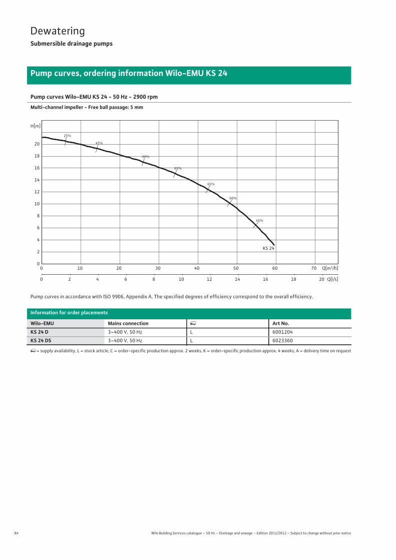
84 Wilo Building Services catalogue – 50 Hz – Drainage and sewage – Edition 2011/2012 – Subject to change without prior notice
DewateringSubmersible drainage pumps
Pump curves, ordering information Wilo-EMU KS 24
Pump curves Wilo-EMU KS 24 - 50 Hz - 2900 rpm
Multi-channel impeller - Free ball passage: 5 mm
Pump curves in accordance with ISO 9906, Appendix A. The specified degrees of efficiency correspond to the overall efficiency.
Information for order placements
Wilo-EMU Mains connection � Art No.KS 24 D 3~400 V, 50 Hz L 6001204
KS 24 DS 3~400 V, 50 Hz L 6023360
�= supply availability, L = stock article, C = order-specific production approx. 2 weeks, K = order-specific production approx. 4 weeks, A = delivery time on request
25%
45%
45%
60%
60%
65%
65%
KS 24
Q[m³/h]0 10 20 30 40 50 60 70
Q[l/s]0 2 4 6 8 10 12 14 16 18 20
H[m]
0
2
4
6
8
10
12
14
16
18
20

85
DewateringSubmersible drainage pumps
Wilo Building Services catalogue – 50 Hz – Drainage and sewage – Edition 2011/2012 – Subject to change without prior notice
Technical data Wilo-EMU KS 24
Dew
ater
ing
KS 24 D KS 24 DS
Motor data
Mains connection 3~400 V, 50 Hz
Nominal current IN / A 4.70 4.70
Nominal motor power P2 / kW 2.4 2.4
Power consumption P1 / kW 2.8 2.8
Activation type Direct Direct
Nominal speed n / rpm 2900 2900
Insulation class F F
Max. switching frequency 1/h 15 15
Cable
Length of connecting cable m 20 20
Cable type H07RN-F H07RN-F
Cable cross-section mm2 4G1,5 4G1,5
Type of connecting cable Detachable Detachable
Mains plug CEE M 16 W CEE M 16 WDSHA
Pump
Pressure connection G 3 G 3
Free ball passage mm 5 5
Operating mode (immersed) S1 S1
Operating mode (non-immersed) S1 S1
Max. immersion depth m 12.5 12.5
Protection class IP 68 IP 68
Fluid temperature T / °C +3 ... +40 +3 ... +40
Max. fluid temperature, for short periods up to 3 min T / °C – –
Weight approx. m / kg 34 34
Equipment/function
Float switch – •Motor protection – –
Explosion protection – –
Materials
Static seal VITON VITON
Impeller EN-GJS-500-7 EN-GJS-500-7
Sealing on motor side C/Al-oxides C/Al-oxides
Sealing on pump side SiC/SiC SiC/SiC
Motor housing G-Al Si12 G-Al Si12
Pump housing EN-GJL-250 EN-GJL-250
P1 refers to the maximum power consumption. All of the data apply to 1~230 V or 3~400 V, 50 Hz and a density of 1 kg/dm3.
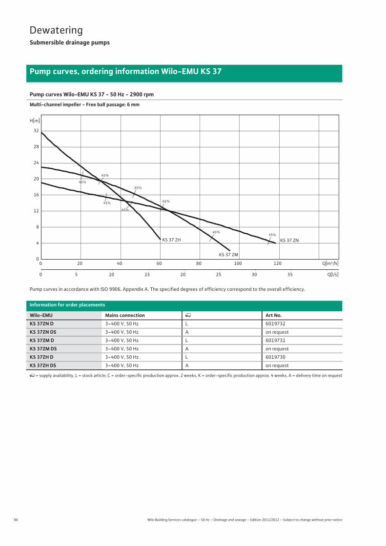
86 Wilo Building Services catalogue – 50 Hz – Drainage and sewage – Edition 2011/2012 – Subject to change without prior notice
DewateringSubmersible drainage pumps
Pump curves, ordering information Wilo-EMU KS 37
Pump curves Wilo-EMU KS 37 - 50 Hz - 2900 rpm
Multi-channel impeller - Free ball passage: 6 mm
Pump curves in accordance with ISO 9906, Appendix A. The specified degrees of efficiency correspond to the overall efficiency.
Information for order placements
Wilo-EMU Mains connection � Art No.KS 37ZN D 3~400 V, 50 Hz L 6019732
KS 37ZN DS 3~400 V, 50 Hz A on request
KS 37ZM D 3~400 V, 50 Hz L 6019731
KS 37ZM DS 3~400 V, 50 Hz A on request
KS 37ZH D 3~400 V, 50 Hz L 6019730
KS 37ZH DS 3~400 V, 50 Hz A on request
�= supply availability, L = stock article, C = order-specific production approx. 2 weeks, K = order-specific production approx. 4 weeks, A = delivery time on request
45%
45%
45%
45%
45%
45%
65%
65%
KS 37 ZM
KS 37 ZNKS 37 ZH
Q[m³/h]0 20 40 60 80 100 120
Q[l/s]0 5 10 15 20 25 30 35
H[m]
0
4
8
12
16
20
24
28
32

87
DewateringSubmersible drainage pumps
Wilo Building Services catalogue – 50 Hz – Drainage and sewage – Edition 2011/2012 – Subject to change without prior notice
Technical data Wilo-EMU KS 37
Dew
ater
ing
KS 37ZN D KS 37ZN DS KS 37ZM D
Motor data
Mains connection 3~400 V, 50 Hz
Nominal current IN / A 8.00 8.00 8.00
Nominal motor power P2 / kW 3.7 3.7 3.7
Power consumption P1 / kW 4.9 4.9 4.9
Activation type Direct Direct Direct
Nominal speed n / rpm 2900 2900 2900
Insulation class F F F
Max. switching frequency 1/h 15 15 15
Cable
Length of connecting cable m 20 20 20
Cable type NSSHÖU NSSHÖU NSSHÖU
Cable cross-section mm2 4G1,5 4G1,5 4G1,5
Type of connecting cable Detachable Detachable Detachable
Mains plug CEE M 16 W CEE M 16 WDSHA CEE M 16 W
Pump
Pressure connection G 4 G 4 G 4
Free ball passage mm 6 6 6
Operating mode (immersed) S1 S1 S1
Operating mode (non-immersed) S1 S1 S1
Max. immersion depth m 12.5 12.5 12.5
Protection class IP 68 IP 68 IP 68
Fluid temperature T / °C +3 ... +40 +3 ... +40 +3 ... +40
Max. fluid temperature, for short periods up to 3 min T / °C – – –
Weight approx. m / kg 66 66 66
Equipment/function
Float switch – • –
Motor protection – – –
Explosion protection – – –
Materials
Static seal VITON VITON VITON
Impeller EN-GJS-500-7 EN-GJS-500-7 EN-GJS-500-7
Sealing on motor side C/Al-oxides C/Al-oxides C/Al-oxides
Sealing on pump side SiC/SiC SiC/SiC SiC/SiC
Motor housing G-Al Si12 G-Al Si12 G-Al Si12
Pump housing EN-GJL-250 EN-GJL-250 EN-GJL-250
P1 refers to the maximum power consumption. All of the data apply to 1~230 V or 3~400 V, 50 Hz and a density of 1 kg/dm3.

88 Wilo Building Services catalogue – 50 Hz – Drainage and sewage – Edition 2011/2012 – Subject to change without prior notice
DewateringSubmersible drainage pumps
Technical data Wilo-EMU KS 37
KS 37ZM DS KS 37ZH D KS 37ZH DS
Motor data
Mains connection 3~400 V, 50 Hz
Nominal current IN / A 8.00 8.00 8.00
Nominal motor power P2 / kW 3.7 3.7 3.7
Power consumption P1 / kW 4.9 4.9 4.9
Activation type Direct Direct Direct
Nominal speed n / rpm 2900 2900 2900
Insulation class F F F
Max. switching frequency 1/h 15 15 15
Cable
Length of connecting cable m 20 20 20
Cable type NSSHÖU NSSHÖU NSSHÖU
Cable cross-section mm2 4G1,5 4G1,5 4G1,5
Type of connecting cable Detachable Detachable Detachable
Mains plug CEE M 16 WDSHA CEE M 16 W CEE M 16 WDSHA
Pump
Pressure connection G 4 G 4 G 4
Free ball passage mm 6 6 6
Operating mode (immersed) S1 S1 S1
Operating mode (non-immersed) S1 S1 S1
Max. immersion depth m 12.5 12.5 12.5
Protection class IP 68 IP 68 IP 68
Fluid temperature T / °C +3 ... +40 +3 ... +40 +3 ... +40
Max. fluid temperature, for short periods up to 3 min T / °C – – –
Weight approx. m / kg 66 66 66
Equipment/function
Float switch • – •Motor protection – – –
Explosion protection – – –
Materials
Static seal VITON VITON VITON
Impeller EN-GJS-500-7 EN-GJS-500-7 EN-GJS-500-7
Sealing on motor side C/Al-oxides C/Al-oxides C/Al-oxides
Sealing on pump side SiC/SiC SiC/SiC SiC/SiC
Motor housing G-Al Si12 G-Al Si12 G-Al Si12
Pump housing EN-GJL-250 EN-GJL-250 EN-GJL-250
P1 refers to the maximum power consumption. All of the data apply to 1~230 V or 3~400 V, 50 Hz and a density of 1 kg/dm3.
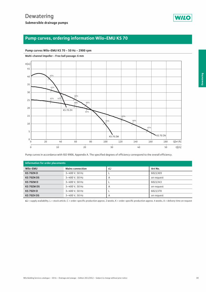
89
DewateringSubmersible drainage pumps
Dew
ater
ing
Pump curves, ordering information Wilo-EMU KS 70
Wilo Building Services catalogue – 50 Hz – Drainage and sewage – Edition 2011/2012 – Subject to change without prior notice
Pump curves Wilo-EMU KS 70 - 50 Hz - 2900 rpm
Multi-channel impeller - Free ball passage: 6 mm
Pump curves in accordance with ISO 9906, Appendix A. The specified degrees of efficiency correspond to the overall efficiency.
Information for order placements
Wilo-EMU Mains connection � Art No.KS 70ZN D 3~400 V, 50 Hz L 6021369
KS 70ZN DS 3~400 V, 50 Hz A on request
KS 70ZM D 3~400 V, 50 Hz L 6021343
KS 70ZM DS 3~400 V, 50 Hz A on request
KS 70ZH D 3~400 V, 50 Hz L 6021370
KS 70ZH DS 3~400 V, 50 Hz A on request
�= supply availability, L = stock article, C = order-specific production approx. 2 weeks, K = order-specific production approx. 4 weeks, A = delivery time on request
45%
45%45%
45%
45%
45%
60%
60%
60%
60%
65%
65%
KS 70 ZH
KS 70 ZM KS 70 ZN
Q[m³/h]0 20 40 60 80 100 120 140 160 180
Q[l/s]0 10 20 30 40 50
H[m]
0
5
10
15
20
25
30
35
40
45
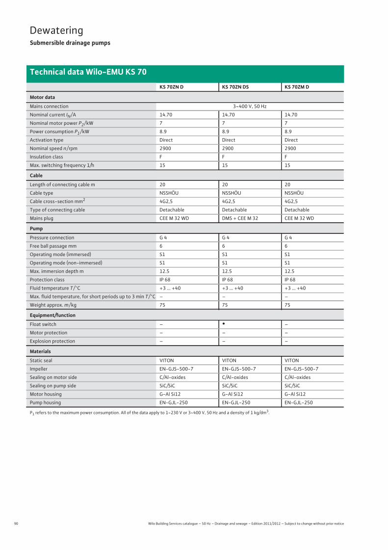
90 Wilo Building Services catalogue – 50 Hz – Drainage and sewage – Edition 2011/2012 – Subject to change without prior notice
DewateringSubmersible drainage pumps
Technical data Wilo-EMU KS 70
KS 70ZN D KS 70ZN DS KS 70ZM D
Motor data
Mains connection 3~400 V, 50 Hz
Nominal current IN / A 14.70 14.70 14.70
Nominal motor power P2 / kW 7 7 7
Power consumption P1 / kW 8.9 8.9 8.9
Activation type Direct Direct Direct
Nominal speed n / rpm 2900 2900 2900
Insulation class F F F
Max. switching frequency 1/h 15 15 15
Cable
Length of connecting cable m 20 20 20
Cable type NSSHÖU NSSHÖU NSSHÖU
Cable cross-section mm2 4G2,5 4G2,5 4G2,5
Type of connecting cable Detachable Detachable Detachable
Mains plug CEE M 32 WD DMS + CEE M 32 CEE M 32 WD
Pump
Pressure connection G 4 G 4 G 4
Free ball passage mm 6 6 6
Operating mode (immersed) S1 S1 S1
Operating mode (non-immersed) S1 S1 S1
Max. immersion depth m 12.5 12.5 12.5
Protection class IP 68 IP 68 IP 68
Fluid temperature T / °C +3 ... +40 +3 ... +40 +3 ... +40
Max. fluid temperature, for short periods up to 3 min T / °C – – –
Weight approx. m / kg 75 75 75
Equipment/function
Float switch – • –
Motor protection – – –
Explosion protection – – –
Materials
Static seal VITON VITON VITON
Impeller EN-GJS-500-7 EN-GJS-500-7 EN-GJS-500-7
Sealing on motor side C/Al-oxides C/Al-oxides C/Al-oxides
Sealing on pump side SiC/SiC SiC/SiC SiC/SiC
Motor housing G-Al Si12 G-Al Si12 G-Al Si12
Pump housing EN-GJL-250 EN-GJL-250 EN-GJL-250
P1 refers to the maximum power consumption. All of the data apply to 1~230 V or 3~400 V, 50 Hz and a density of 1 kg/dm3.

91
DewateringSubmersible drainage pumps
Wilo Building Services catalogue – 50 Hz – Drainage and sewage – Edition 2011/2012 – Subject to change without prior notice
Technical data Wilo-EMU KS 70
Dew
ater
ing
KS 70ZM DS KS 70ZH D KS 70ZH DS
Motor data
Mains connection 3~400 V, 50 Hz
Nominal current IN / A 14.70 15.60 15.60
Nominal motor power P2 / kW 7 7.5 7.5
Power consumption P1 / kW 8.9 9.5 9.5
Activation type Direct Direct Direct
Nominal speed n / rpm 2900 2900 2900
Insulation class F F F
Max. switching frequency 1/h 15 15 15
Cable
Length of connecting cable m 20 20 20
Cable type NSSHÖU NSSHÖU NSSHÖU
Cable cross-section mm2 4G2,5 4G2,5 4G2,5
Type of connecting cable Detachable Detachable Detachable
Mains plug DMS + CEE M 32 CEE M 32 WD DMS + CEE M 32
Pump
Pressure connection G 4 G 4 G 4
Free ball passage mm 6 6 6
Operating mode (immersed) S1 S1 S1
Operating mode (non-immersed) S1 S1 S1
Max. immersion depth m 12.5 12.5 12.5
Protection class IP 68 IP 68 IP 68
Fluid temperature T / °C +3 ... +40 +3 ... +40 +3 ... +40
Max. fluid temperature, for short periods up to 3 min T / °C – – –
Weight approx. m / kg 75 75 75
Equipment/function
Float switch • – •Motor protection – – –
Explosion protection – – –
Materials
Static seal VITON VITON VITON
Impeller EN-GJS-500-7 EN-GJS-500-7 EN-GJS-500-7
Sealing on motor side C/Al-oxides C/Al-oxides C/Al-oxides
Sealing on pump side SiC/SiC SiC/SiC SiC/SiC
Motor housing G-Al Si12 G-Al Si12 G-Al Si12
Pump housing EN-GJL-250 EN-GJL-250 EN-GJL-250
P1 refers to the maximum power consumption. All of the data apply to 1~230 V or 3~400 V, 50 Hz and a density of 1 kg/dm3.
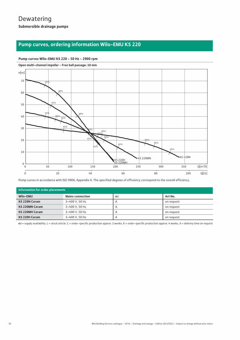
92 Wilo Building Services catalogue – 50 Hz – Drainage and sewage – Edition 2011/2012 – Subject to change without prior notice
DewateringSubmersible drainage pumps
Pump curves, ordering information Wilo-EMU KS 220
Pump curves Wilo-EMU KS 220 - 50 Hz - 2900 rpm
Open multi-channel impeller - Free ball passage: 10 mm
Pump curves in accordance with ISO 9906, Appendix A. The specified degrees of efficiency correspond to the overall efficiency.
Information for order placements
Wilo-EMU Mains connection � Art No.KS 220N Ceram 3~400 V, 50 Hz A on request
KS 220MN Ceram 3~400 V, 50 Hz A on request
KS 220MH Ceram 3~400 V, 50 Hz A on request
KS 220H Ceram 3~400 V, 50 Hz A on request
�= supply availability, L = stock article, C = order-specific production approx. 2 weeks, K = order-specific production approx. 4 weeks, A = delivery time on request
45%
45%
45%
45%
45%
45%
45%
45%
60%
60%
60%
60%
60%
60%
65%
65%
65%
65%
Q[m³/h]0 50 100 150 200 250 300 350
Q[l/s]0 20 40 60 80 100
H[m]
0
10
20
30
40
50
60
70
KS 220MHKS 220H
KS 220N KS 220MN

93
DewateringSubmersible drainage pumps
Wilo Building Services catalogue – 50 Hz – Drainage and sewage – Edition 2011/2012 – Subject to change without prior notice
Technical data Wilo-EMU KS 220
Dew
ater
ing
KS 220N Ceram KS 220MN Ceram KS 220MH Ceram KS 220H Ceram
Motor data
Mains connection 3~400 V, 50 Hz
Nominal current IN / A 40.50 40.50 40.50 40.50
Nominal motor power P2 / kW 22 22 22 22
Power consumption P1 / kW 24.4 24.4 24.4 24.4
Activation type Direct Direct Direct Direct
Nominal speed n / rpm 2900 2900 2900 2900
Insulation class F F F F
Max. switching frequency 1/h 15 15 15 15
Cable
Length of connecting cable m 20 20 20 20
Cable type S07RN-F S07RN-F S07RN-F S07RN-F
Cable cross-section mm2 4G6 4G6 4G6 4G6
Type of connecting cable Non-detachable Non-detachable Non-detachable Non-detachable
Mains plug DSA-G + CEE 63 DSA-G + CEE 63 DSA-G + CEE 63 DSA-G + CEE 63
Pump
Pressure connection G 6 G 6 G 6 G 6
Free ball passage mm 10 10 10 10
Operating mode (immersed) S1 S1 S1 S1
Operating mode (non-immersed) S1 S1 S1 S1
Max. immersion depth m 12.5 12.5 12.5 12.5
Protection class IP 68 IP 68 IP 68 IP 68
Fluid temperature T / °C +3 ... +40 +3 ... +40 +3 ... +40 +3 ... +40
Max. fluid temperature, for short periods up to 3 min T / °C – – – –
Weight approx. m / kg 222 222 222 222
Equipment/function
Float switch – – – –
Motor protection WSK WSK WSK WSK
Explosion protection – – – –
Materials
Static seal VITON VITON VITON VITON
Impeller Abrasite Abrasite Abrasite Abrasite
Sealing on motor side SiC/SiC SiC/SiC SiC/SiC SiC/SiC
Sealing on pump side SiC/SiC SiC/SiC SiC/SiC SiC/SiC
Motor housing G-Al Si12 G-Al Si12 G-Al Si12 G-Al Si12
Pump housing G-Al Si 12 G-Al Si 12 G-Al Si 12 G-Al Si 12
P1 refers to the maximum power consumption. All of the data apply to 1~230 V or 3~400 V, 50 Hz and a density of 1 kg/dm3.
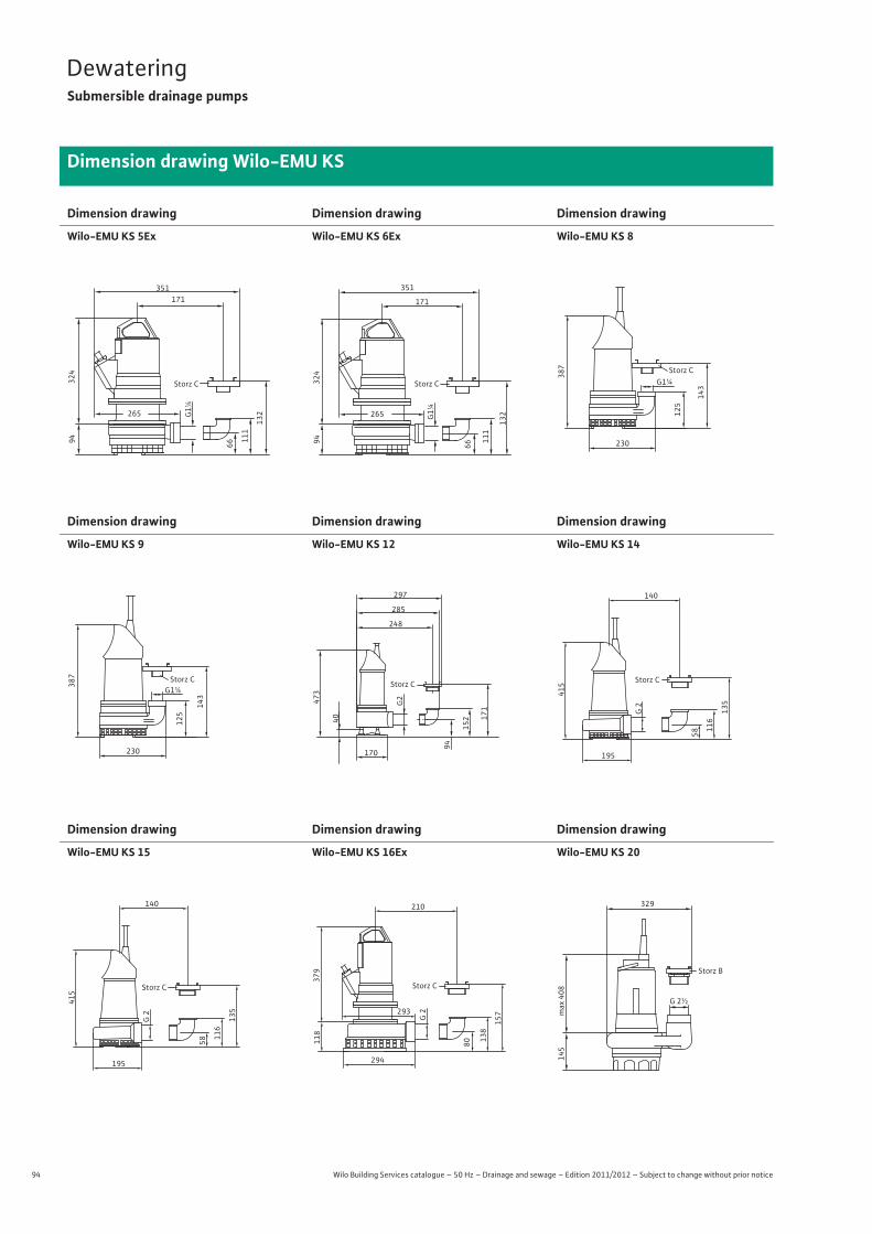
94 Wilo Building Services catalogue – 50 Hz – Drainage and sewage – Edition 2011/2012 – Subject to change without prior notice
DewateringSubmersible drainage pumps
Dimension drawing Wilo-EMU KS
Dimension drawing
Wilo-EMU KS 5Ex
Dimension drawing
Wilo-EMU KS 6Ex
Dimension drawing
Wilo-EMU KS 8
Dimension drawing
Wilo-EMU KS 9
Dimension drawing
Wilo-EMU KS 12
Dimension drawing
Wilo-EMU KS 14
Dimension drawing
Wilo-EMU KS 15
Dimension drawing
Wilo-EMU KS 16Ex
Dimension drawing
Wilo-EMU KS 20
265
66
G1¼
111
132
Storz C
94
171
324
351
265
Storz C
66
111
132
94
G1¼
171
324
351
387
125
143
G1¼
230
Storz C
387
125
143
G1¼
230
Storz C
170
40
G2
94
152 17
1
248
Storz C
285
297
473
G 2
58 116
135
195
140
Storz C
415
195
140
Storz C
415
58 116
135
G 2
118
293
80 138
210
Storz C
294
157
379
G 2
145
Storz B
329
G 2½
max
408
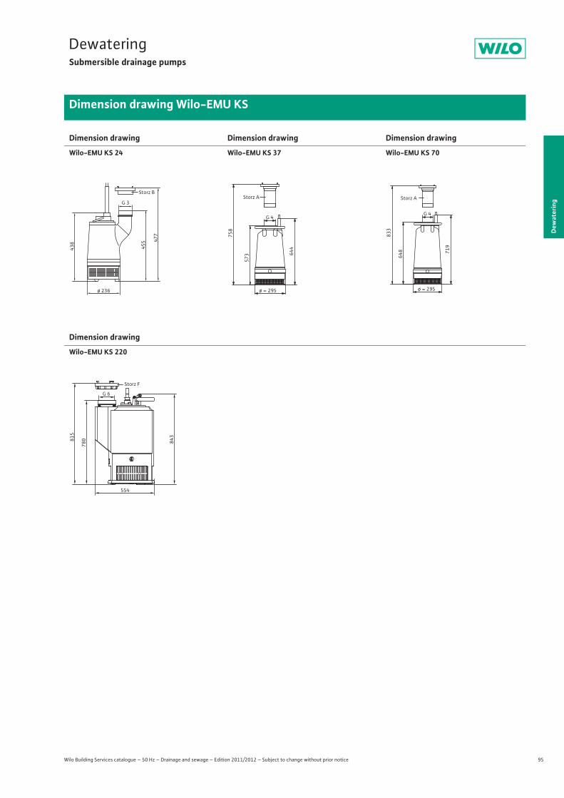
95
DewateringSubmersible drainage pumps
Dew
ater
ing
Dimension drawing Wilo-EMU KS
Wilo Building Services catalogue – 50 Hz – Drainage and sewage – Edition 2011/2012 – Subject to change without prior notice
Dimension drawing
Wilo-EMU KS 24
Dimension drawing
Wilo-EMU KS 37
Dimension drawing
Wilo-EMU KS 70
Dimension drawing
Wilo-EMU KS 220
455
438
ø 236
477
Storz B
G 3
644
573
G 4
Storz A
758
ø = 295
833
648 719
G 4
Storz A
ø = 295
843
554
780
G 6
Storz F
815
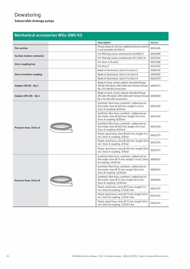
96 Wilo Building Services catalogue – 50 Hz – Drainage and sewage – Edition 2011/2012 – Subject to change without prior notice
DewateringSubmersible drainage pumps
Mechanical accessories Wilo-EMU KS
Description Art no.
Flat suction Pumps down to 10 mm, additional level control is not possible; KS 8/KS 9 6032495
Suction strainer extensionFor filtering coarse constituents; KS 8/KS 9 6032496
For filtering coarse constituents; KS 14/KS 15 6032616
Storz coupling keyFor Storz A, B and C 6022280
For Storz F 6022281
Storz transition couplingMade of aluminium, Storz B to Storz C 6000748
Made of aluminium, Storz A to Storz B 6003026
Made of aluminium, Storz F to Storz A 6022279
Adapter DN 80 - Rp 3Made of steel, nickel-plated, threaded flange DN 80, PN 10/16, DIN 2566 with female thread Rp 3 for DN 80 connection
6003672
Adapter DN 100 - Rp 4Made of steel, nickel-plated, threaded flange DN 100, PN 10/16, DIN 2566 with female thread Rp 4 for DN 100 connection
6003669
Pressure hose / Storz A
Synthetic fibre hose, synthetic, rubberized on the inside, inner Ø 102 mm, length 5 m incl. Storz A coupling, 8/20 bar
6022391
Synthetic fibre hose, synthetic, rubberized on the inside, inner Ø 102 mm, length 10 m incl. Storz A coupling, 8/20 bar
6022392
Synthetic fibre hose, synthetic, rubberized on the inside, inner Ø 102 mm, length 20 m incl. Storz A coupling, 8/20 bar
6022393
Plastic spiral hose, inner Ø 102 mm, length 5 m incl. Storz A coupling, 3/9 bar 6022275
Plastic spiral hose, inner Ø 102 mm, length 10 m incl. Storz A coupling, 3/9 bar 6022276
Plastic spiral hose, inner Ø 102 mm, length 20 m incl. Storz A coupling, 3/9 bar 6022277
Pressure hose / Storz B
Synthetic fibre hose, synthetic, rubberized on the inside, inner Ø 75 mm, length 5 m incl. Storz B coupling, 12/40 bar
6003052
Synthetic fibre hose, synthetic, rubberized on the inside, inner Ø 75 mm, length 10 m incl. Storz B coupling, 12/40 bar
6003051
Synthetic fibre hose, synthetic, rubberized on the inside, inner Ø 75 mm, length 20 m incl. Storz B coupling, 12/40 bar
6003050
Plastic spiral hose, inner Ø 75 mm, length 5 m incl. Storz B coupling, 3.5/10.5 bar 6022272
Plastic spiral hose, inner Ø 75 mm, length 10 m incl. Storz B coupling, 3.5/10.5 bar 6035187
Plastic spiral hose, inner Ø 75 mm, length 20 m incl. Storz B coupling, 3.5/10.5 bar 6022274
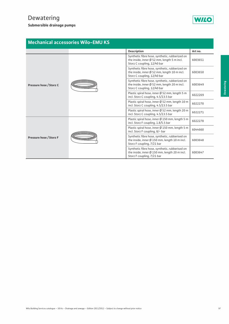
97
DewateringSubmersible drainage pumps
Wilo Building Services catalogue – 50 Hz – Drainage and sewage – Edition 2011/2012 – Subject to change without prior notice
Mechanical accessories Wilo-EMU KS
Dew
ater
ing
Pressure hose / Storz C
Synthetic fibre hose, synthetic, rubberized on the inside, inner Ø 52 mm, length 5 m incl. Storz C coupling, 12/40 bar
6003651
Synthetic fibre hose, synthetic, rubberized on the inside, inner Ø 52 mm, length 10 m incl. Storz C coupling, 12/40 bar
6003650
Synthetic fibre hose, synthetic, rubberized on the inside, inner Ø 52 mm, length 20 m incl. Storz C coupling, 12/40 bar
6003649
Plastic spiral hose, inner Ø 52 mm, length 5 m incl. Storz C coupling, 4.5/13.5 bar 6022269
Plastic spiral hose, inner Ø 52 mm, length 10 m incl. Storz C coupling, 4.5/13.5 bar 6022270
Plastic spiral hose, inner Ø 52 mm, length 20 m incl. Storz C coupling, 4.5/13.5 bar 6022271
Pressure hose / Storz F
Plastic spiral hose, inner Ø 150 mm, length 5 m incl. Storz F coupling, 1.8/5.5 bar 6022278
Plastic spiral hose, inner Ø 150 mm, length 5 m incl. Storz F coupling, 8/- bar 6044660
Synthetic fibre hose, synthetic, rubberised on the inside, inner Ø 150 mm, length 10 m incl. Storz F coupling, 7/21 bar
6003648
Synthetic fibre hose, synthetic, rubberised on the inside, inner Ø 150 mm, length 20 m incl. Storz F coupling, 7/21 bar
6003647
Description Art no.
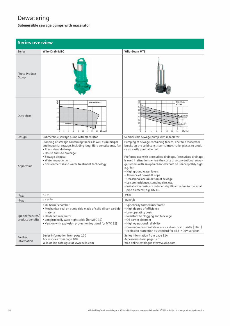
98 Wilo Building Services catalogue – 50 Hz – Drainage and sewage – Edition 2011/2012 – Subject to change without prior notice
DewateringSubmersible sewage pumps with macerator
Series overview
Series Wilo-Drain MTC Wilo-Drain MTS
Photo Product Group
Duty chart
Design Submersible sewage pump with macerator Submersible sewage pump with macerator
Application
Pumping of sewage containing faeces as well as municipal and industrial sewage, including long-fibre constituents, for:• Pressurised drainage• House and site drainage• Sewage disposal• Water management• Environmental and water treatment technology
Pumping of sewage containing faeces. The Wilo macerator breaks up the solid constituents into smaller pieces to produ-ce an easily pumpable fluid.
Preferred use with pressurised drainage. Pressurised drainage is used in situations where the costs of a conventional sewa-ge system with an open channel would be unacceptably high, e.g. for:• High ground water levels• Absence of downhill slope• Occasional accumulation of sewage• Leisure residence, camping site, etc.• Installation costs are reduced significantly due to the small pipe diameter, e.g. DN 40.
Hmax 55 m 39 m
Qmax 17 m3/h 16 m3/h
Special features/product benefits
• Oil barrier chamber• Mechanical seal on pump side made of solid silicon carbide
material• Hardened macerator• Longitudinally watertight cable (for MTC 32)• Version with explosion protection (optional for MTC 32)
• Spherically formed macerator• High degree of efficiency• Low operating costs• Resistant to clogging and blockage• Oil barrier chamber• High operational reliability• Corrosion-resistant stainless steel motor in 1.4404 (316 L)• Explosion protection as standard for all 3~400V versions
Furtherinformation
Series information from page 100 Accessories from page 108Wilo online catalogue at www.wilo.com
Series information from page 114 Accessories from page 120Wilo online catalogue at www.wilo.com
Q[m³/h]0 2 4 6 8 10 12 14 16
H[m
]
0
10
20
30
40
50
Wilo-Drain MTC
Q[m³/h]420 86 10 12 14
H[m
]
0
5
10
15
20
25
30
35
Wilo-DrainMTS 40
MTS 40/31
MTS 40/24MTS 40/27
MTS 40/21
MTS 40/39
MTS 40/35
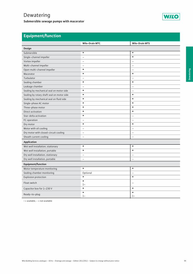
99
DewateringSubmersible sewage pumps with macerator
Wilo Building Services catalogue – 50 Hz – Drainage and sewage – Edition 2011/2012 – Subject to change without prior notice
Equipment/function
Dew
ater
ing
Wilo-Drain MTC Wilo-Drain MTS
Design
Submersible • •Single-channel impeller – •Vortex impeller – –
Multi-channel impeller – –
Open multi-channel impeller • –
Macerator • •Turbulator – –
Sealing chamber • •Leakage chamber – –
Sealing by mechanical seal on motor side • –
Sealing by rotary shaft seal on motor side • •Sealing by mechanical seal on fluid side • •Single-phase AC motor • •Three-phase motor • •Direct activation • •Star-delta activation • –
FC operation – –
Dry motor • •Motor with oil cooling – –
Dry motor with closed-circuit cooling – –
Sheath current cooling – –
Application
Wet well installation, stationary • •Wet well installation, portable • •Dry well installation, stationary – –
Dry well installation, portable – –
Equipment/function
Motor temperature monitoring • •Sealing chamber monitoring Optional –
Explosion protection • •Float switch •
1~ –
Capacitor box for 1~230 V • •Ready-to-plug •
1~•1~
• = available, - = not available
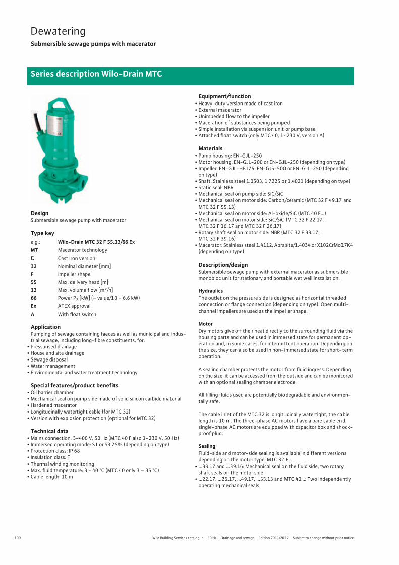
100 Wilo Building Services catalogue – 50 Hz – Drainage and sewage – Edition 2011/2012 – Subject to change without prior notice
DewateringSubmersible sewage pumps with macerator
Series description Wilo-Drain MTC
DesignSubmersible sewage pump with macerator
Type key
ApplicationPumping of sewage containing faeces as well as municipal and indus-trial sewage, including long-fibre constituents, for:
• Pressurised drainage• House and site drainage• Sewage disposal• Water management• Environmental and water treatment technology
Special features/product benefits• Oil barrier chamber• Mechanical seal on pump side made of solid silicon carbide material• Hardened macerator• Longitudinally watertight cable (for MTC 32)• Version with explosion protection (optional for MTC 32)
Technical data• Mains connection: 3~400 V, 50 Hz (MTC 40 F also 1~230 V, 50 Hz)• Immersed operating mode: S1 or S3 25% (depending on type)• Protection class: IP 68• Insulation class: F• Thermal winding monitoring• Max. fluid temperature: 3 - 40 °C (MTC 40 only 3 – 35 °C)• Cable length: 10 m
Equipment/function• Heavy-duty version made of cast iron• External macerator• Unimpeded flow to the impeller• Maceration of substances being pumped• Simple installation via suspension unit or pump base• Attached float switch (only MTC 40, 1~230 V, version A)
Materials• Pump housing: EN-GJL-250• Motor housing: EN-GJL-200 or EN-GJL-250 (depending on type)• Impeller: EN-GJL-HB175, EN-GJS-500 or EN-GJL-250 (depending on type)
• Shaft: Stainless steel 1.0503, 1.7225 or 1.4021 (depending on type)• Static seal: NBR• Mechanical seal on pump side: SiC/SiC• Mechanical seal on motor side: Carbon/ceramic (MTC 32 F 49.17 and
MTC 32 F 55.13)• Mechanical seal on motor side: Al-oxide/SiC (MTC 40 F...)• Mechanical seal on motor side: SiC/SiC (MTC 32 F 22.17,
MTC 32 F 16.17 and MTC 32 F 26.17)• Rotary shaft seal on motor side: NBR (MTC 32 F 33.17,
MTC 32 F 39.16)• Macerator: Stainless steel 1.4112, Abrasite/1.4034 or X102CrMo17K4
(depending on type)
Description/designSubmersible sewage pump with external macerator as submersible monobloc unit for stationary and portable wet well installation.
HydraulicsThe outlet on the pressure side is designed as horizontal threaded connection or flange connection (depending on type). Open multi-channel impellers are used as the impeller shape.
MotorDry motors give off their heat directly to the surrounding fluid via the housing parts and can be used in immersed state for permanent op-eration and, in some cases, for intermittent operation. Depending on the size, they can also be used in non-immersed state for short-term operation.
A sealing chamber protects the motor from fluid ingress. Depending on the size, it can be accessed from the outside and can be monitored with an optional sealing chamber electrode.
All filling fluids used are potentially biodegradable and environmen-tally safe.
The cable inlet of the MTC 32 is longitudinally watertight, the cable length is 10 m. The three-phase AC motors have a bare cable end, single-phase AC motors are equipped with capacitor box and shock-proof plug.
SealingFluid-side and motor-side sealing is available in different versions depending on the motor type: MTC 32 F...
• ...33.17 and ...39.16: Mechanical seal on the fluid side, two rotary shaft seals on the motor side
• ...22.17, ...26.17, ...49.17, ...55.13 and MTC 40...: Two independently operating mechanical seals
e.g.: Wilo-Drain MTC 32 F 55.13/66 ExMT Macerator technologyC Cast iron version32 Nominal diameter [mm]F Impeller shape55 Max. delivery head [m]13 Max. volume flow [m3/h]66 Power P2 [kW] (= value/10 = 6.6 kW)Ex ATEX approvalA With float switch
101
DewateringSubmersible sewage pumps with macerator
Dew
ater
ing
Series description Wilo-Drain MTC
Wilo Building Services catalogue – 50 Hz – Drainage and sewage – Edition 2011/2012 – Subject to change without prior notice
Options• Length of the power cable in 20 m, 30 m, 40 m and 50 m
(for MTC 32 F 16 to MTC 32 F 33)
Scope of delivery• Pump ready for connection with 10 m connection cable
- For 3~400 V with bare cable end- For 1~230 V with shock-proof plug
• A-model version with attached float switch• Installation and operating instructions
CommissioningS1 operating mode with non-immersed motor:Dry motors can be non-immersed only if there is an operating mode for non-immersed operation.
Dry-running protection system:The hydraulic housing must always be immersed to prevent air from being drawn in. In the case of fluctuating fluid levels, the system should shut down automatically once the minimum water submer-sion is reached.
Accessories• Suspension unit and pump base• Chains• Switchgears, relays and plugs
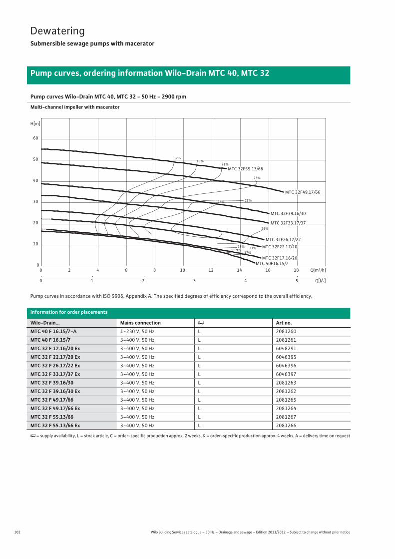
102 Wilo Building Services catalogue – 50 Hz – Drainage and sewage – Edition 2011/2012 – Subject to change without prior notice
DewateringSubmersible sewage pumps with macerator
Pump curves, ordering information Wilo-Drain MTC 40, MTC 32
Pump curves Wilo-Drain MTC 40, MTC 32 - 50 Hz - 2900 rpm
Multi-channel impeller with macerator
Pump curves in accordance with ISO 9906, Appendix A. The specified degrees of efficiency correspond to the overall efficiency.
Information for order placements
Wilo-Drain... Mains connection � Art no.MTC 40 F 16.15/7-A 1~230 V, 50 Hz L 2081260
MTC 40 F 16.15/7 3~400 V, 50 Hz L 2081261
MTC 32 F 17.16/20 Ex 3~400 V, 50 Hz L 6048291
MTC 32 F 22.17/20 Ex 3~400 V, 50 Hz L 6046395
MTC 32 F 26.17/22 Ex 3~400 V, 50 Hz L 6046396
MTC 32 F 33.17/37 Ex 3~400 V, 50 Hz L 6046397
MTC 32 F 39.16/30 3~400 V, 50 Hz L 2081263
MTC 32 F 39.16/30 Ex 3~400 V, 50 Hz L 2081262
MTC 32 F 49.17/66 3~400 V, 50 Hz L 2081265
MTC 32 F 49.17/66 Ex 3~400 V, 50 Hz L 2081264
MTC 32 F 55.13/66 3~400 V, 50 Hz L 2081267
MTC 32 F 55.13/66 Ex 3~400 V, 50 Hz L 2081266
�= supply availability, L = stock article, C = order-specific production approx. 2 weeks, K = order-specific production approx. 4 weeks, A = delivery time on request
17%
17%
19%
19%
21%
21%
23%
23%
25%
25%
27%
Q[m³/h]0 2 4 6 8 10 12 14 16 18
Q[l/s]0 1 2 3 4 5
H[m]
0
10
20
30
40
50
60
MTC 32F17.16/20
MTC 32F26.17/22
MTC 40F16.15/7
MTC 32F55.13/66
MTC 32F22.17/20
MTC 32F49.17/66
MTC 32F33.17/37
MTC 32F39.16/30
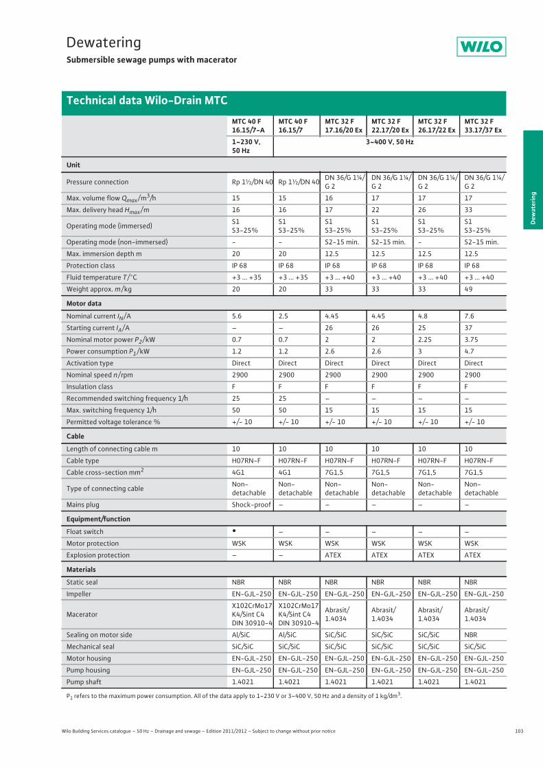
103
DewateringSubmersible sewage pumps with macerator
Wilo Building Services catalogue – 50 Hz – Drainage and sewage – Edition 2011/2012 – Subject to change without prior notice
Technical data Wilo-Drain MTC
Dew
ater
ing
MTC 40 F 16.15/7-A
MTC 40 F 16.15/7
MTC 32 F 17.16/20 Ex
MTC 32 F 22.17/20 Ex
MTC 32 F 26.17/22 Ex
MTC 32 F 33.17/37 Ex
1~230 V, 50 Hz
3~400 V, 50 Hz
Unit
Pressure connection Rp 1½/DN 40 Rp 1½/DN 40 DN 36/G 1¼/G 2
DN 36/G 1¼/G 2
DN 36/G 1¼/G 2
DN 36/G 1¼/G 2
Max. volume flow Qmax / m3/h 15 15 16 17 17 17
Max. delivery head Hmax / m 16 16 17 22 26 33
Operating mode (immersed) S1S3-25%
S1S3-25%
S1S3-25%
S1S3-25%
S1S3-25%
S1S3-25%
Operating mode (non-immersed) - - S2-15 min. S2-15 min. - S2-15 min.
Max. immersion depth m 20 20 12.5 12.5 12.5 12.5
Protection class IP 68 IP 68 IP 68 IP 68 IP 68 IP 68
Fluid temperature T / °C +3 ... +35 +3 ... +35 +3 ... +40 +3 ... +40 +3 ... +40 +3 ... +40
Weight approx. m / kg 20 20 33 33 33 49
Motor data
Nominal current IN / A 5.6 2.5 4.45 4.45 4.8 7.6
Starting current IA / A – – 26 26 25 37
Nominal motor power P2 / kW 0.7 0.7 2 2 2.25 3.75
Power consumption P1 / kW 1.2 1.2 2.6 2.6 3 4.7
Activation type Direct Direct Direct Direct Direct Direct
Nominal speed n / rpm 2900 2900 2900 2900 2900 2900
Insulation class F F F F F F
Recommended switching frequency 1/h 25 25 – – – –
Max. switching frequency 1/h 50 50 15 15 15 15
Permitted voltage tolerance % +/- 10 +/- 10 +/- 10 +/- 10 +/- 10 +/- 10
Cable
Length of connecting cable m 10 10 10 10 10 10
Cable type H07RN-F H07RN-F H07RN-F H07RN-F H07RN-F H07RN-F
Cable cross-section mm2 4G1 4G1 7G1,5 7G1,5 7G1,5 7G1,5
Type of connecting cable Non-detachable
Non-detachable
Non-detachable
Non-detachable
Non-detachable
Non-detachable
Mains plug Shock-proof – – – – –
Equipment/function
Float switch • – – – – –
Motor protection WSK WSK WSK WSK WSK WSK
Explosion protection – – ATEX ATEX ATEX ATEX
Materials
Static seal NBR NBR NBR NBR NBR NBR
Impeller EN-GJL-250 EN-GJL-250 EN-GJL-250 EN-GJL-250 EN-GJL-250 EN-GJL-250
Macerator X102CrMo17K4/Sint C4 DIN 30910-4
X102CrMo17K4/Sint C4 DIN 30910-4
Abrasit/1.4034
Abrasit/1.4034
Abrasit/1.4034
Abrasit/1.4034
Sealing on motor side Al/SiC Al/SiC SiC/SiC SiC/SiC SiC/SiC NBR
Mechanical seal SiC/SiC SiC/SiC SiC/SiC SiC/SiC SiC/SiC SiC/SiC
Motor housing EN-GJL-250 EN-GJL-250 EN-GJL-250 EN-GJL-250 EN-GJL-250 EN-GJL-250
Pump housing EN-GJL-250 EN-GJL-250 EN-GJL-250 EN-GJL-250 EN-GJL-250 EN-GJL-250
Pump shaft 1.4021 1.4021 1.4021 1.4021 1.4021 1.4021
P1 refers to the maximum power consumption. All of the data apply to 1~230 V or 3~400 V, 50 Hz and a density of 1 kg/dm3.
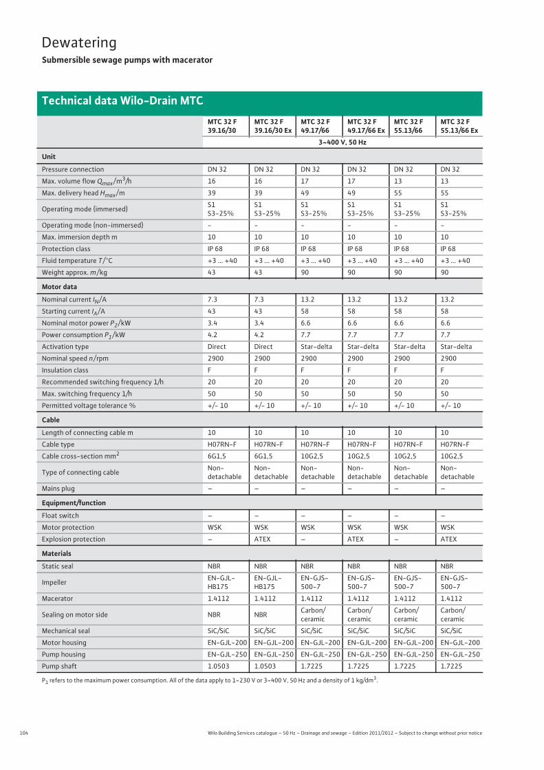
104 Wilo Building Services catalogue – 50 Hz – Drainage and sewage – Edition 2011/2012 – Subject to change without prior notice
DewateringSubmersible sewage pumps with macerator
Technical data Wilo-Drain MTC
MTC 32 F 39.16/30
MTC 32 F 39.16/30 Ex
MTC 32 F 49.17/66
MTC 32 F 49.17/66 Ex
MTC 32 F 55.13/66
MTC 32 F 55.13/66 Ex
3~400 V, 50 Hz
Unit
Pressure connection DN 32 DN 32 DN 32 DN 32 DN 32 DN 32
Max. volume flow Qmax / m3/h 16 16 17 17 13 13
Max. delivery head Hmax / m 39 39 49 49 55 55
Operating mode (immersed) S1S3-25%
S1S3-25%
S1S3-25%
S1S3-25%
S1S3-25%
S1S3-25%
Operating mode (non-immersed) - - - - - -
Max. immersion depth m 10 10 10 10 10 10
Protection class IP 68 IP 68 IP 68 IP 68 IP 68 IP 68
Fluid temperature T / °C +3 ... +40 +3 ... +40 +3 ... +40 +3 ... +40 +3 ... +40 +3 ... +40
Weight approx. m / kg 43 43 90 90 90 90
Motor data
Nominal current IN / A 7.3 7.3 13.2 13.2 13.2 13.2
Starting current IA / A 43 43 58 58 58 58
Nominal motor power P2 / kW 3.4 3.4 6.6 6.6 6.6 6.6
Power consumption P1 / kW 4.2 4.2 7.7 7.7 7.7 7.7
Activation type Direct Direct Star-delta Star-delta Star-delta Star-delta
Nominal speed n / rpm 2900 2900 2900 2900 2900 2900
Insulation class F F F F F F
Recommended switching frequency 1/h 20 20 20 20 20 20
Max. switching frequency 1/h 50 50 50 50 50 50
Permitted voltage tolerance % +/- 10 +/- 10 +/- 10 +/- 10 +/- 10 +/- 10
Cable
Length of connecting cable m 10 10 10 10 10 10
Cable type H07RN-F H07RN-F H07RN-F H07RN-F H07RN-F H07RN-F
Cable cross-section mm2 6G1,5 6G1,5 10G2,5 10G2,5 10G2,5 10G2,5
Type of connecting cable Non-detachable
Non-detachable
Non-detachable
Non-detachable
Non-detachable
Non-detachable
Mains plug – – – – – –
Equipment/function
Float switch – – – – – –
Motor protection WSK WSK WSK WSK WSK WSK
Explosion protection – ATEX – ATEX – ATEX
Materials
Static seal NBR NBR NBR NBR NBR NBR
Impeller EN-GJL-HB175
EN-GJL-HB175
EN-GJS-500-7
EN-GJS-500-7
EN-GJS-500-7
EN-GJS-500-7
Macerator 1.4112 1.4112 1.4112 1.4112 1.4112 1.4112
Sealing on motor side NBR NBR Carbon/ceramic
Carbon/ceramic
Carbon/ceramic
Carbon/ceramic
Mechanical seal SiC/SiC SiC/SiC SiC/SiC SiC/SiC SiC/SiC SiC/SiC
Motor housing EN-GJL-200 EN-GJL-200 EN-GJL-200 EN-GJL-200 EN-GJL-200 EN-GJL-200
Pump housing EN-GJL-250 EN-GJL-250 EN-GJL-250 EN-GJL-250 EN-GJL-250 EN-GJL-250
Pump shaft 1.0503 1.0503 1.7225 1.7225 1.7225 1.7225
P1 refers to the maximum power consumption. All of the data apply to 1~230 V or 3~400 V, 50 Hz and a density of 1 kg/dm3.

105
DewateringSubmersible sewage pumps with macerator
Dew
ater
ing
Dimensions Wilo-Drain MTC 40, MTC 32
Wilo Building Services catalogue – 50 Hz – Drainage and sewage – Edition 2011/2012 – Subject to change without prior notice
Dimension drawing Wilo-Drain MTC 40 - stationary wet well installation
Dimension drawing Wilo-Drain MTC 40 - portable wet well installation
80
8875
110 73
801440
Ø12
105
265
18
125
130
> 110
>24
Ø 600
Ø26,9
+
Ø 1000+
250200
+
363
2434
0
310
(300
-330
)
15
155
11014
110
140
220
50
123145
73
363 22
0
90
316
DN 40/Rp 1½
260
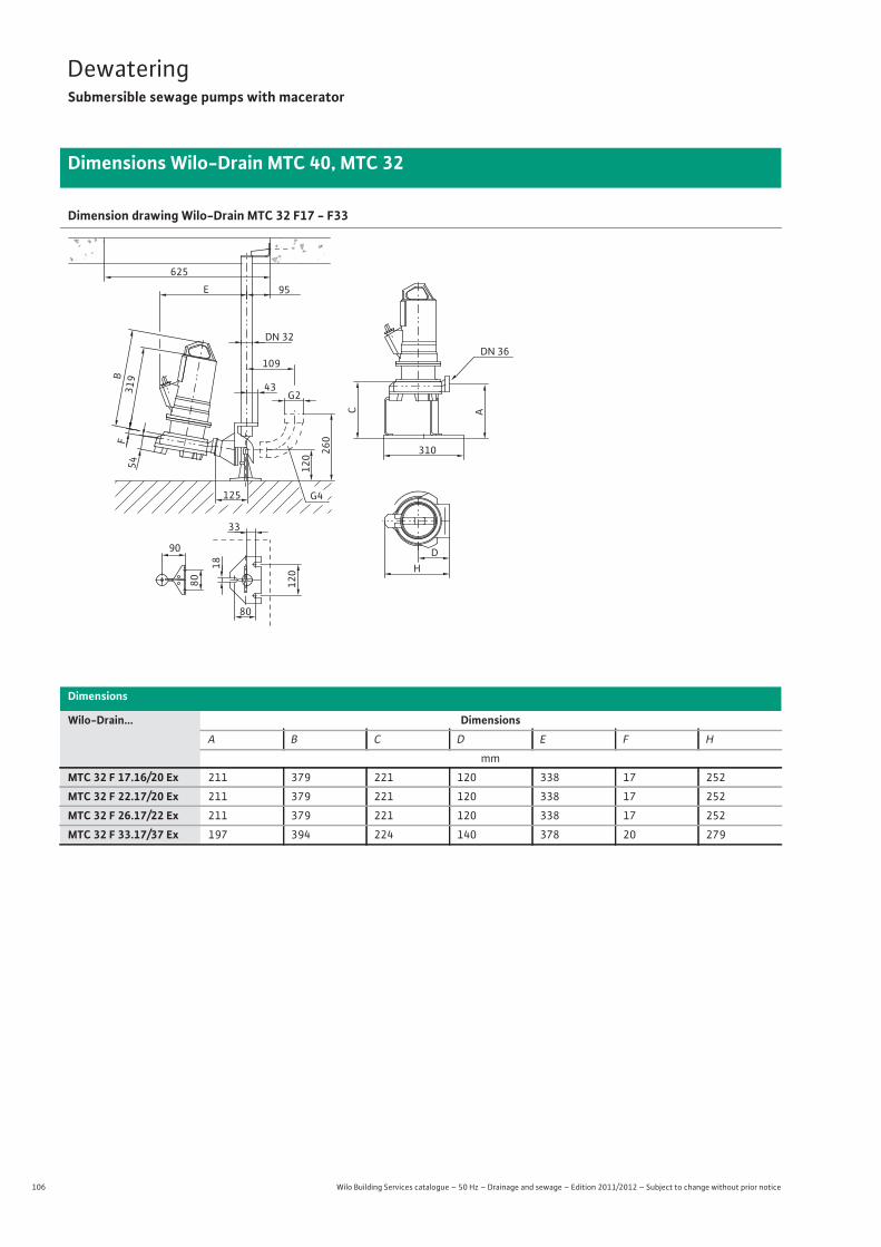
106 Wilo Building Services catalogue – 50 Hz – Drainage and sewage – Edition 2011/2012 – Subject to change without prior notice
DewateringSubmersible sewage pumps with macerator
Dimensions Wilo-Drain MTC 40, MTC 32
Dimension drawing Wilo-Drain MTC 32 F17 - F33
Dimensions
Wilo-Drain... DimensionsA B C D E F H
mm
MTC 32 F 17.16/20 Ex 211 379 221 120 338 17 252
MTC 32 F 22.17/20 Ex 211 379 221 120 338 17 252
MTC 32 F 26.17/22 Ex 211 379 221 120 338 17 252
MTC 32 F 33.17/37 Ex 197 394 224 140 378 20 279
B
33
319
95
G2
120 26
0
109
G4125
DN 32
E
54F
43
80
18
120
80
90
625
DN 36
DH
A
310
C
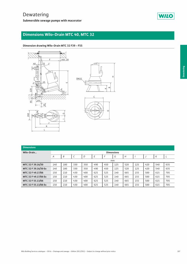
107
DewateringSubmersible sewage pumps with macerator
Dew
ater
ing
Dimensions Wilo-Drain MTC 40, MTC 32
Wilo Building Services catalogue – 50 Hz – Drainage and sewage – Edition 2011/2012 – Subject to change without prior notice
Dimension drawing Wilo-Drain MTC 32 F39 - F55
Dimensions
Wilo-Drain... DimensionsA B C D E F G H I J K L
mm
MTC 32 F 39.16/30 140 180 330 350 490 450 125 520 125 420 540 635
MTC 32 F 39.16/30 Ex 140 180 330 350 490 450 125 520 125 420 540 635
MTC 32 F 49.17/66 150 210 430 400 625 525 140 665 155 500 615 705
MTC 32 F 49.17/66 Ex 150 210 430 400 625 525 140 665 155 500 615 705
MTC 32 F 55.13/66 150 210 430 400 625 525 140 665 155 500 615 705
MTC 32 F 55.13/66 Ex 150 210 430 400 625 525 140 665 155 500 615 705
I
JK
L
G
260
F
5540 1“
2“ 15
145
3xØ12
220
95
95
R ca.150
min. 20
E
D
C
DN32
H
B A
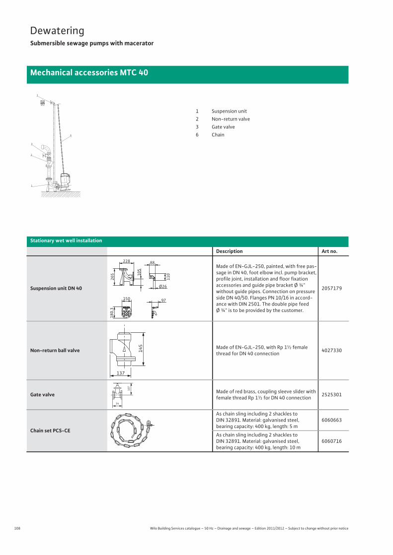
108 Wilo Building Services catalogue – 50 Hz – Drainage and sewage – Edition 2011/2012 – Subject to change without prior notice
DewateringSubmersible sewage pumps with macerator
Mechanical accessories MTC 40
Stationary wet well installation
Description Art no.
Suspension unit DN 40
Made of EN-GJL-250, painted, with free pas-sage in DN 40, foot elbow incl. pump bracket, profile joint, installation and floor fixationaccessories and guide pipe bracket Ø ¾" without guide pipes. Connection on pressure side DN 40/50. Flanges PN 10/16 in accord-ance with DIN 2501. The double pipe feedØ ¾" is to be provided by the customer.
2057179
Non-return ball valve Made of EN-GJL-250, with Rp 1½ female thread for DN 40 connection 4027330
Gate valve Made of red brass, coupling sleeve slider with female thread Rp 1½ for DN 40 connection 2525301
Chain set PCS-CE
As chain sling including 2 shackles to DIN 32891. Material: galvanised steel, bearing capacity: 400 kg, length: 5 m
6060663
As chain sling including 2 shackles to DIN 32891. Material: galvanised steel, bearing capacity: 400 kg, length: 10 m
6060716
1
3
2
1
6
1 Suspension unit2 Non-return valve3 Gate valve6 Chain
105
228
265
88
110
Ø26
150
180,
3
97
145
137
54
107
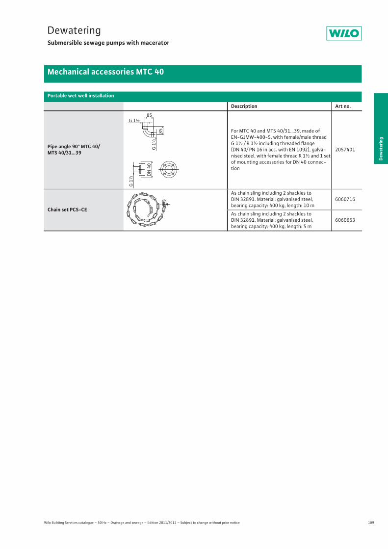
109
DewateringSubmersible sewage pumps with macerator
Dew
ater
ing
Mechanical accessories MTC 40
Wilo Building Services catalogue – 50 Hz – Drainage and sewage – Edition 2011/2012 – Subject to change without prior notice
Portable wet well installation
Description Art no.
Pipe angle 90° MTC 40/MTS 40/31...39
For MTC 40 and MTS 40/31...39, made of EN-GJMW-400-5, with female/male thread G 1½ / R 1½ including threaded flange (DN 40/ PN 16 in acc. with EN 1092), galva-nised steel, with female thread R 1½ and 1 set of mounting accessories for DN 40 connec-tion
2057401
Chain set PCS-CE
As chain sling including 2 shackles to DIN 32891. Material: galvanised steel, bearing capacity: 400 kg, length: 10 m
6060716
As chain sling including 2 shackles to DIN 32891. Material: galvanised steel, bearing capacity: 400 kg, length: 5 m
6060663
G 1½
G 1
½
G 1
½
DN
40
85
85
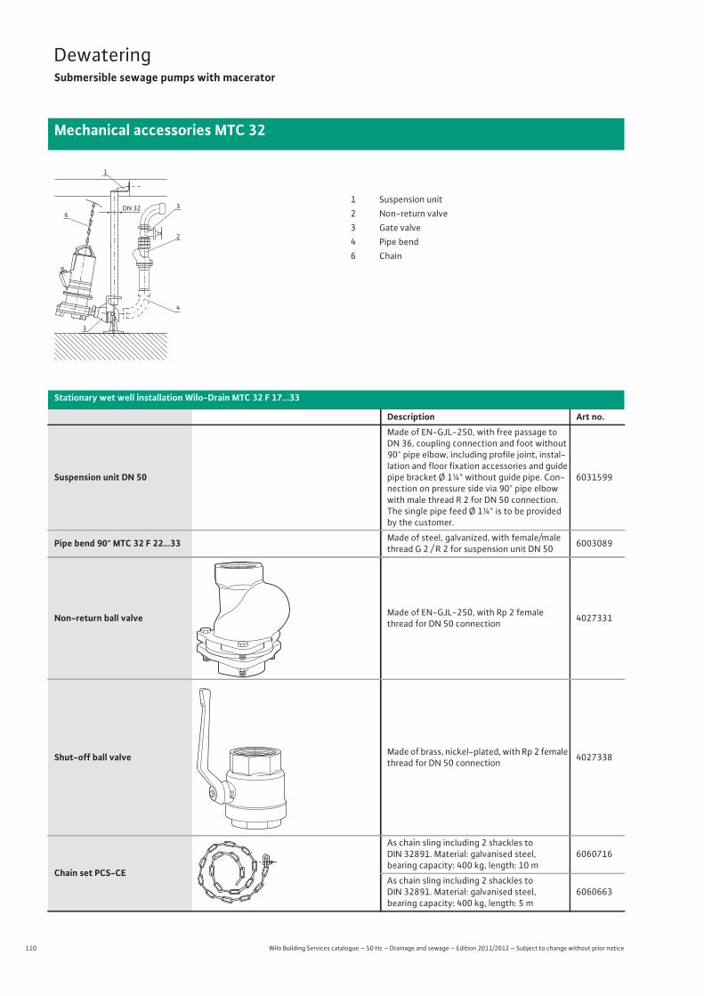
110 Wilo Building Services catalogue – 50 Hz – Drainage and sewage – Edition 2011/2012 – Subject to change without prior notice
DewateringSubmersible sewage pumps with macerator
Mechanical accessories MTC 32
DN 32 3
2
4
6
1
1
1 Suspension unit2 Non-return valve3 Gate valve4 Pipe bend6 Chain
Stationary wet well installation Wilo-Drain MTC 32 F 17...33
Description Art no.
Suspension unit DN 50
Made of EN-GJL-250, with free passage to DN 36, coupling connection and foot without 90° pipe elbow, including profile joint, instal-lation and floor fixation accessories and guide pipe bracket Ø 1¼" without guide pipe. Con-nection on pressure side via 90° pipe elbow with male thread R 2 for DN 50 connection. The single pipe feed Ø 1¼" is to be provided by the customer.
6031599
Pipe bend 90° MTC 32 F 22...33 Made of steel, galvanized, with female/male thread G 2 / R 2 for suspension unit DN 50 6003089
Non-return ball valve Made of EN-GJL-250, with Rp 2 female thread for DN 50 connection 4027331
Shut-off ball valve Made of brass, nickel-plated, with Rp 2 female thread for DN 50 connection 4027338
Chain set PCS-CE
As chain sling including 2 shackles to DIN 32891. Material: galvanised steel, bearing capacity: 400 kg, length: 10 m
6060716
As chain sling including 2 shackles to DIN 32891. Material: galvanised steel, bearing capacity: 400 kg, length: 5 m
6060663
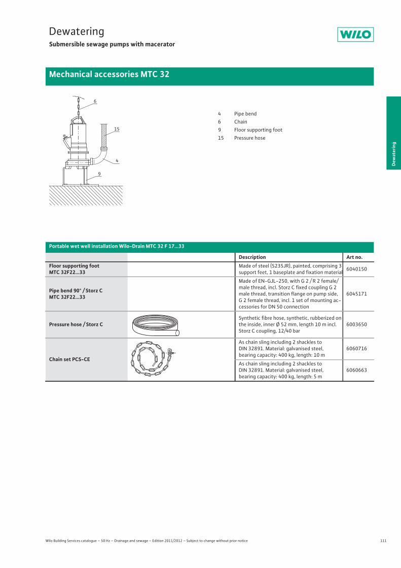
111
DewateringSubmersible sewage pumps with macerator
Dew
ater
ing
Mechanical accessories MTC 32
Wilo Building Services catalogue – 50 Hz – Drainage and sewage – Edition 2011/2012 – Subject to change without prior notice
Portable wet well installation Wilo-Drain MTC 32 F 17...33
Description Art no.Floor supporting footMTC 32F22...33
Made of steel (S235JR), painted, comprising 3 support feet, 1 baseplate and fixation material 6040150
Pipe bend 90° / Storz CMTC 32F22...33
Made of EN-GJL-250, with G 2 / R 2 female/male thread, incl. Storz C fixed coupling G 2 male thread, transition flange on pump side, G 2 female thread, incl. 1 set of mounting ac-cessories for DN 50 connection
6045171
Pressure hose / Storz CSynthetic fibre hose, synthetic, rubberized on the inside, inner Ø 52 mm, length 10 m incl. Storz C coupling, 12/40 bar
6003650
Chain set PCS-CE
As chain sling including 2 shackles to DIN 32891. Material: galvanised steel, bearing capacity: 400 kg, length: 10 m
6060716
As chain sling including 2 shackles to DIN 32891. Material: galvanised steel, bearing capacity: 400 kg, length: 5 m
6060663
6
15
4
9
4 Pipe bend6 Chain9 Floor supporting foot15 Pressure hose
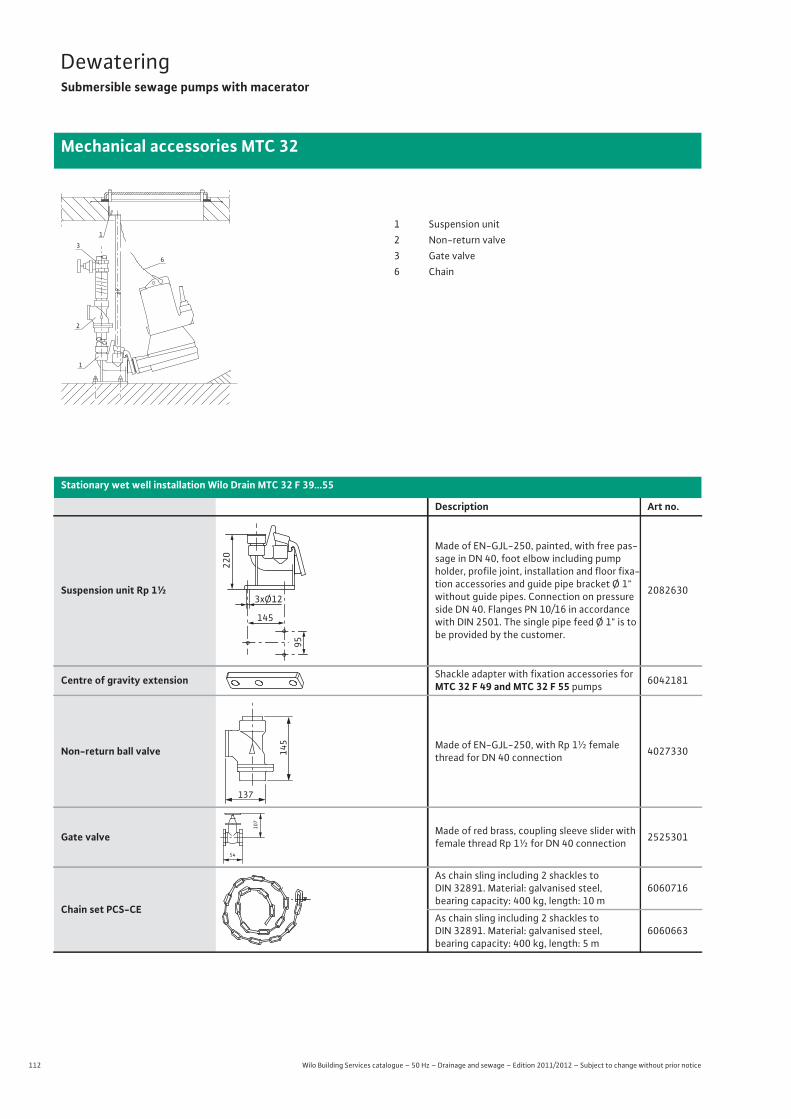
112 Wilo Building Services catalogue – 50 Hz – Drainage and sewage – Edition 2011/2012 – Subject to change without prior notice
DewateringSubmersible sewage pumps with macerator
Mechanical accessories MTC 32
Stationary wet well installation Wilo Drain MTC 32 F 39...55
Description Art no.
Suspension unit Rp 1½
Made of EN-GJL-250, painted, with free pas-sage in DN 40, foot elbow including pump holder, profile joint, installation and floor fixa-tion accessories and guide pipe bracket Ø 1" without guide pipes. Connection on pressure side DN 40. Flanges PN 10/16 in accordance with DIN 2501. The single pipe feed Ø 1" is to be provided by the customer.
2082630
Centre of gravity extension Shackle adapter with fixation accessories for MTC 32 F 49 and MTC 32 F 55 pumps 6042181
Non-return ball valve Made of EN-GJL-250, with Rp 1½ female thread for DN 40 connection 4027330
Gate valve Made of red brass, coupling sleeve slider with female thread Rp 1½ for DN 40 connection 2525301
Chain set PCS-CE
As chain sling including 2 shackles to DIN 32891. Material: galvanised steel, bearing capacity: 400 kg, length: 10 m
6060716
As chain sling including 2 shackles to DIN 32891. Material: galvanised steel, bearing capacity: 400 kg, length: 5 m
6060663
6
3
2
1
11 Suspension unit2 Non-return valve3 Gate valve6 Chain
145
3xØ12
220
9514
5
137
54
107
113
DewateringSubmersible sewage pumps with macerator
Dew
ater
ing
Mechanical accessories MTC 32
Wilo Building Services catalogue – 50 Hz – Drainage and sewage – Edition 2011/2012 – Subject to change without prior notice
Portable wet well installation Wilo Drain MTC 32 F 39...55
Description Art no.
Floor supporting footMTC 32 F 49...55
Made of steel (S235JR), painted, consisting of 3 supporting feet, 1 ground plate and fixation material
2098296
Floor supporting footMTC 32 F 39
Made of steel (S235JR), painted, consisting of 3 supporting feet, 1 ground plate and fixation material
2098295
Chain set PCS-CE
As chain sling including 2 shackles to DIN 32891. Material: galvanised steel, bearing capacity: 400 kg, length: 10 m
6060716
As chain sling including 2 shackles to DIN 32891. Material: galvanised steel, bearing capacity: 400 kg, length: 5 m
6060663
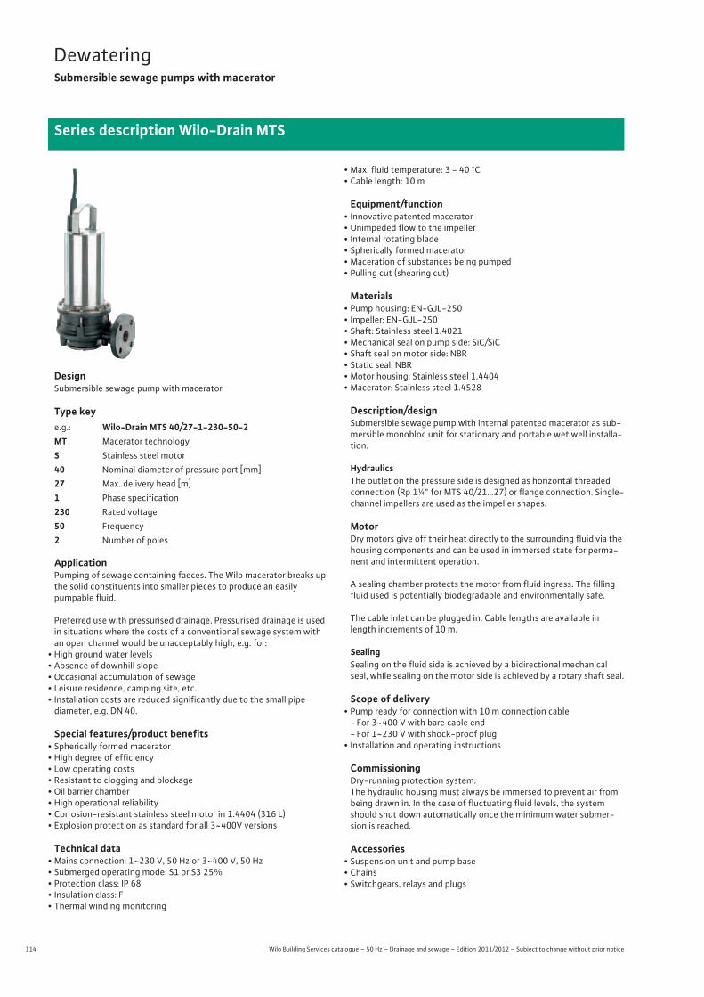
114 Wilo Building Services catalogue – 50 Hz – Drainage and sewage – Edition 2011/2012 – Subject to change without prior notice
DewateringSubmersible sewage pumps with macerator
Series description Wilo-Drain MTS
DesignSubmersible sewage pump with macerator
Type key
ApplicationPumping of sewage containing faeces. The Wilo macerator breaks up the solid constituents into smaller pieces to produce an easily pumpable fluid.
Preferred use with pressurised drainage. Pressurised drainage is used in situations where the costs of a conventional sewage system with an open channel would be unacceptably high, e.g. for:
• High ground water levels• Absence of downhill slope• Occasional accumulation of sewage• Leisure residence, camping site, etc.• Installation costs are reduced significantly due to the small pipe
diameter, e.g. DN 40.
Special features/product benefits• Spherically formed macerator• High degree of efficiency• Low operating costs• Resistant to clogging and blockage• Oil barrier chamber• High operational reliability• Corrosion-resistant stainless steel motor in 1.4404 (316 L)• Explosion protection as standard for all 3~400V versions
Technical data• Mains connection: 1~230 V, 50 Hz or 3~400 V, 50 Hz• Submerged operating mode: S1 or S3 25%• Protection class: IP 68• Insulation class: F• Thermal winding monitoring
• Max. fluid temperature: 3 - 40 °C• Cable length: 10 m
Equipment/function• Innovative patented macerator• Unimpeded flow to the impeller• Internal rotating blade• Spherically formed macerator• Maceration of substances being pumped• Pulling cut (shearing cut)
Materials• Pump housing: EN-GJL-250• Impeller: EN-GJL-250• Shaft: Stainless steel 1.4021• Mechanical seal on pump side: SiC/SiC• Shaft seal on motor side: NBR• Static seal: NBR• Motor housing: Stainless steel 1.4404• Macerator: Stainless steel 1.4528
Description/designSubmersible sewage pump with internal patented macerator as sub-mersible monobloc unit for stationary and portable wet well installa-tion.
HydraulicsThe outlet on the pressure side is designed as horizontal threaded connection (Rp 1¼" for MTS 40/21…27) or flange connection. Single-channel impellers are used as the impeller shapes.
MotorDry motors give off their heat directly to the surrounding fluid via the housing components and can be used in immersed state for perma-nent and intermittent operation.
A sealing chamber protects the motor from fluid ingress. The filling fluid used is potentially biodegradable and environmentally safe.
The cable inlet can be plugged in. Cable lengths are available in length increments of 10 m.
SealingSealing on the fluid side is achieved by a bidirectional mechanical seal, while sealing on the motor side is achieved by a rotary shaft seal.
Scope of delivery• Pump ready for connection with 10 m connection cable
- For 3~400 V with bare cable end- For 1~230 V with shock-proof plug
• Installation and operating instructions
CommissioningDry-running protection system:The hydraulic housing must always be immersed to prevent air from being drawn in. In the case of fluctuating fluid levels, the system should shut down automatically once the minimum water submer-sion is reached.
Accessories• Suspension unit and pump base• Chains• Switchgears, relays and plugs
e.g.: Wilo-Drain MTS 40/27-1-230-50-2MT Macerator technologyS Stainless steel motor40 Nominal diameter of pressure port [mm]27 Max. delivery head [m]1 Phase specification230 Rated voltage50 Frequency2 Number of poles
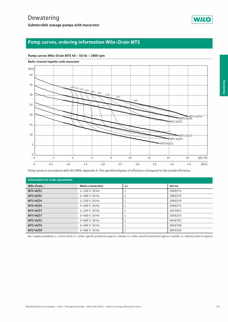
115
DewateringSubmersible sewage pumps with macerator
Dew
ater
ing
Pump curves, ordering information Wilo-Drain MTS
Wilo Building Services catalogue – 50 Hz – Drainage and sewage – Edition 2011/2012 – Subject to change without prior notice
Pump curves Wilo-Drain MTS 40 - 50 Hz - 2900 rpm
Multi-channel impeller with macerator
Pump curves in accordance with ISO 9906, Appendix A. The specified degrees of efficiency correspond to the overall efficiency.
Information for order placements
Wilo-Drain... Mains connection � Art no.MTS 40/21 1~230 V, 50 Hz L 2060174
MTS 40/21 3~400 V, 50 Hz L 2060176
MTS 40/24 1~230 V, 50 Hz L 2060170
MTS 40/24 3~400 V, 50 Hz L 2060175
MTS 40/27 1~230 V, 50 Hz L 2053831
MTS 40/27 3~400 V, 50 Hz L 2056253
MTS 40/31 3~400 V, 50 Hz L 6046761
MTS 40/35 3~400 V, 50 Hz L 6046760
MTS 40/39 3~400 V, 50 Hz L 6045558
�= supply availability, L = stock article, C = order-specific production approx. 2 weeks, K = order-specific production approx. 4 weeks, A = delivery time on request
20%22% 24% 26% 28%30%
32%34%
36%
MTS 40/31
MTS 40/24
Q[m³/h]0 2 4 6 8 10 12 14 16
Q[l/s]0 0,5 1,0 1,5 2,0 2,5 3,0 3,5 4,0 4,5
H[m]
0
5
10
15
20
25
30
35
40
MTS 40/27
MTS 40/21
MTS 40/39MTS 40/35
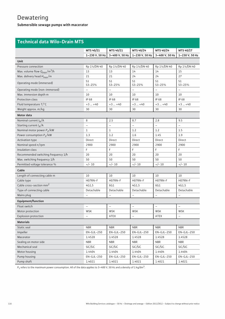
116 Wilo Building Services catalogue – 50 Hz – Drainage and sewage – Edition 2011/2012 – Subject to change without prior notice
DewateringSubmersible sewage pumps with macerator
Technical data Wilo-Drain MTS
MTS 40/21 MTS 40/21 MTS 40/24 MTS 40/24 MTS 40/271~230 V, 50 Hz 3~400 V, 50 Hz 1~230 V, 50 Hz 3~400 V, 50 Hz 1~230 V, 50 Hz
Unit
Pressure connection Rp 1¼/DN 40 Rp 1¼/DN 40 Rp 1¼/DN 40 Rp 1¼/DN 40 Rp 1¼/DN 40
Max. volume flow Qmax / m3/h 13 13 14 14 15
Max. delivery head Hmax / m 21 21 24 24 27
Operating mode (immersed) S1S3-25%
S1S3-25%
S1S3-25%
S1S3-25%
S1S3-25%
Operating mode (non-immersed) – – – – –
Max. immersion depth m 10 10 10 10 10
Protection class IP 68 IP 68 IP 68 IP 68 IP 68
Fluid temperature T / °C +3 ... +40 +3 ... +40 +3 ... +40 +3 ... +40 +3 ... +40
Weight approx. m / kg 30 30 30 30 30
Motor data
Nominal current IN / A 8 2.5 8.7 2.8 9.5
Starting current IA / A – – – – –
Nominal motor power P2 / kW 1 1 1.2 1.2 1.5
Power consumption P1 / kW 1.3 1.2 1.6 1.45 1.9
Activation type Direct Direct Direct Direct Direct
Nominal speed n / rpm 2900 2900 2900 2900 2900
Insulation class F F F F F
Recommended switching frequency 1/h 20 20 20 20 20
Max. switching frequency 1/h 50 50 50 50 50
Permitted voltage tolerance % +/- 10 +/- 10 +/- 10 +/- 10 +/- 10
Cable
Length of connecting cable m 10 10 10 10 10
Cable type H07RN-F H07RN-F H07RN-F H07RN-F H07RN-F
Cable cross-section mm2 4G1,5 6G1 4G1,5 6G1 4G1,5
Type of connecting cable Detachable Detachable Detachable Detachable Detachable
Mains plug – – – – –
Equipment/function
Float switch – – – – –
Motor protection WSK WSK WSK WSK WSK
Explosion protection – ATEX – ATEX –
Materials
Static seal NBR NBR NBR NBR NBR
Impeller EN-GJL-250 EN-GJL-250 EN-GJL-250 EN-GJL-250 EN-GJL-250
Macerator 1.4528 1.4528 1.4528 1.4528 1.4528
Sealing on motor side NBR NBR NBR NBR NBR
Mechanical seal SiC/SiC SiC/SiC SiC/SiC SiC/SiC SiC/SiC
Motor housing 1.4404 1.4404 1.4404 1.4404 1.4404
Pump housing EN-GJL-250 EN-GJL-250 EN-GJL-250 EN-GJL-250 EN-GJL-250
Pump shaft 1.4021 1.4021 1.4021 1.4021 1.4021
P1 refers to the maximum power consumption. All of the data applies to 3~400 V, 50 Hz and a density of 1 kg/dm3.
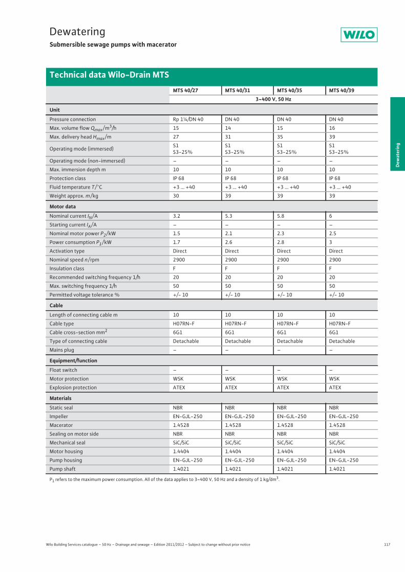
117
DewateringSubmersible sewage pumps with macerator
Wilo Building Services catalogue – 50 Hz – Drainage and sewage – Edition 2011/2012 – Subject to change without prior notice
Technical data Wilo-Drain MTS
Dew
ater
ing
MTS 40/27 MTS 40/31 MTS 40/35 MTS 40/393~400 V, 50 Hz
Unit
Pressure connection Rp 1¼/DN 40 DN 40 DN 40 DN 40
Max. volume flow Qmax / m3/h 15 14 15 16
Max. delivery head Hmax / m 27 31 35 39
Operating mode (immersed) S1S3-25%
S1S3-25%
S1S3-25%
S1S3-25%
Operating mode (non-immersed) – – – –
Max. immersion depth m 10 10 10 10
Protection class IP 68 IP 68 IP 68 IP 68
Fluid temperature T / °C +3 ... +40 +3 ... +40 +3 ... +40 +3 ... +40
Weight approx. m / kg 30 39 39 39
Motor data
Nominal current IN / A 3.2 5.3 5.8 6
Starting current IA / A – – – –
Nominal motor power P2 / kW 1.5 2.1 2.3 2.5
Power consumption P1 / kW 1.7 2.6 2.8 3
Activation type Direct Direct Direct Direct
Nominal speed n / rpm 2900 2900 2900 2900
Insulation class F F F F
Recommended switching frequency 1/h 20 20 20 20
Max. switching frequency 1/h 50 50 50 50
Permitted voltage tolerance % +/- 10 +/- 10 +/- 10 +/- 10
Cable
Length of connecting cable m 10 10 10 10
Cable type H07RN-F H07RN-F H07RN-F H07RN-F
Cable cross-section mm2 6G1 6G1 6G1 6G1
Type of connecting cable Detachable Detachable Detachable Detachable
Mains plug – – – –
Equipment/function
Float switch – – – –
Motor protection WSK WSK WSK WSK
Explosion protection ATEX ATEX ATEX ATEX
Materials
Static seal NBR NBR NBR NBR
Impeller EN-GJL-250 EN-GJL-250 EN-GJL-250 EN-GJL-250
Macerator 1.4528 1.4528 1.4528 1.4528
Sealing on motor side NBR NBR NBR NBR
Mechanical seal SiC/SiC SiC/SiC SiC/SiC SiC/SiC
Motor housing 1.4404 1.4404 1.4404 1.4404
Pump housing EN-GJL-250 EN-GJL-250 EN-GJL-250 EN-GJL-250
Pump shaft 1.4021 1.4021 1.4021 1.4021
P1 refers to the maximum power consumption. All of the data applies to 3~400 V, 50 Hz and a density of 1 kg/dm3.
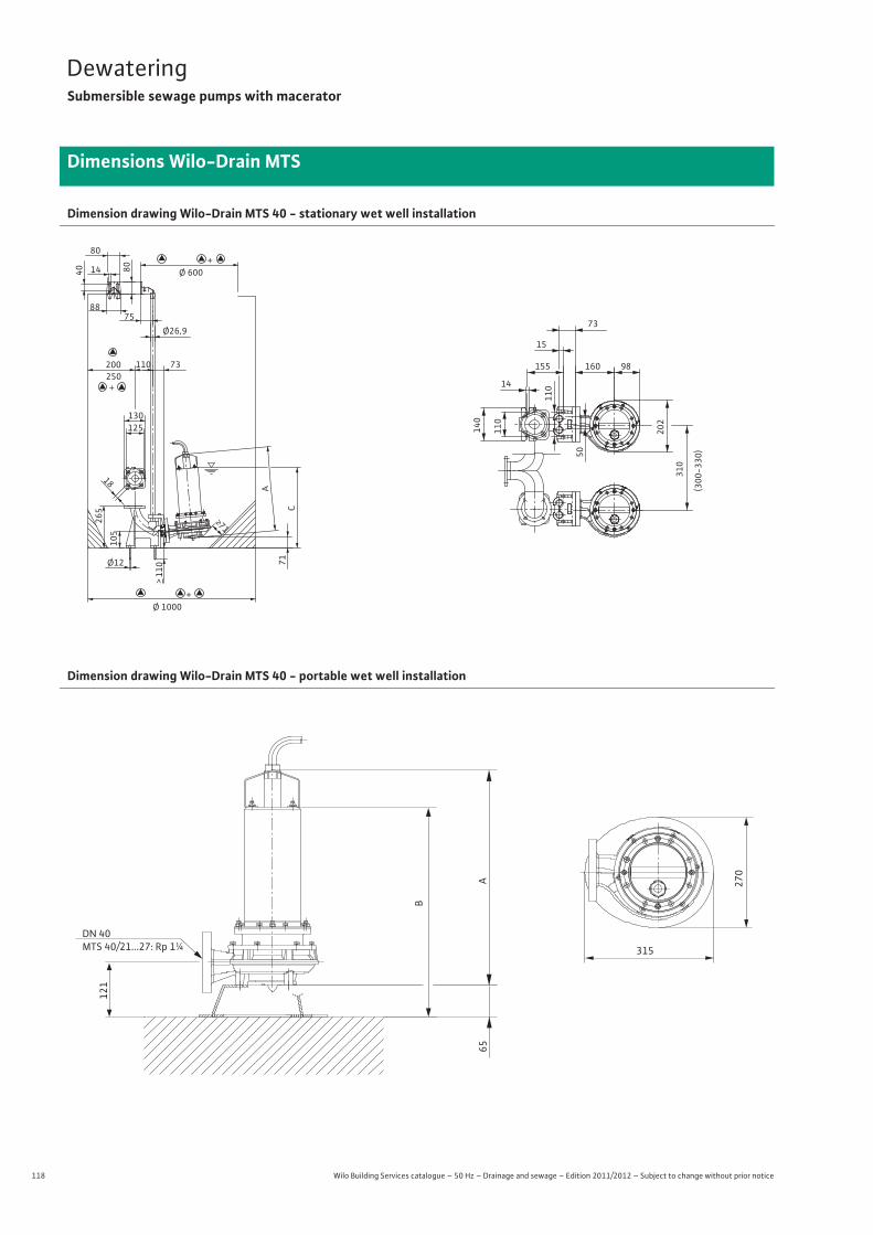
118 Wilo Building Services catalogue – 50 Hz – Drainage and sewage – Edition 2011/2012 – Subject to change without prior notice
DewateringSubmersible sewage pumps with macerator
Dimensions Wilo-Drain MTS
Dimension drawing Wilo-Drain MTS 40 - stationary wet well installation
Dimension drawing Wilo-Drain MTS 40 - portable wet well installation
Ø12
> 11
0 71
75
250200
Ø26,9
73110
125130
265 C
A
Ø 1000
Ø 600
>71
14
18
80
80
40
88
310
(300
-330
)
98160
73
15
155
11014
110
140
202
50
105
+
+
+
65A
121
270
315
B
DN 40MTS 40/21...27: Rp 1¼
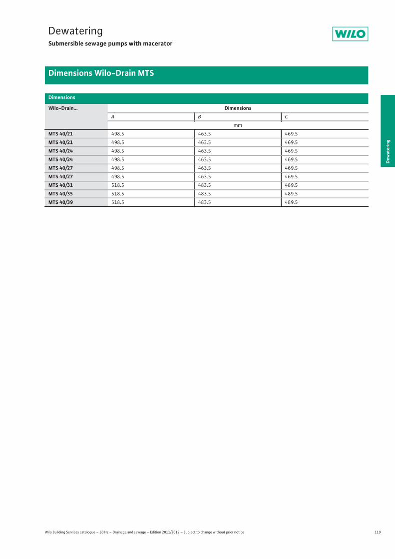
119
DewateringSubmersible sewage pumps with macerator
Dew
ater
ing
Dimensions Wilo-Drain MTS
Wilo Building Services catalogue – 50 Hz – Drainage and sewage – Edition 2011/2012 – Subject to change without prior notice
Dimensions
Wilo-Drain... DimensionsA B C
mm
MTS 40/21 498.5 463.5 469.5
MTS 40/21 498.5 463.5 469.5
MTS 40/24 498.5 463.5 469.5
MTS 40/24 498.5 463.5 469.5
MTS 40/27 498.5 463.5 469.5
MTS 40/27 498.5 463.5 469.5
MTS 40/31 518.5 483.5 489.5
MTS 40/35 518.5 483.5 489.5
MTS 40/39 518.5 483.5 489.5
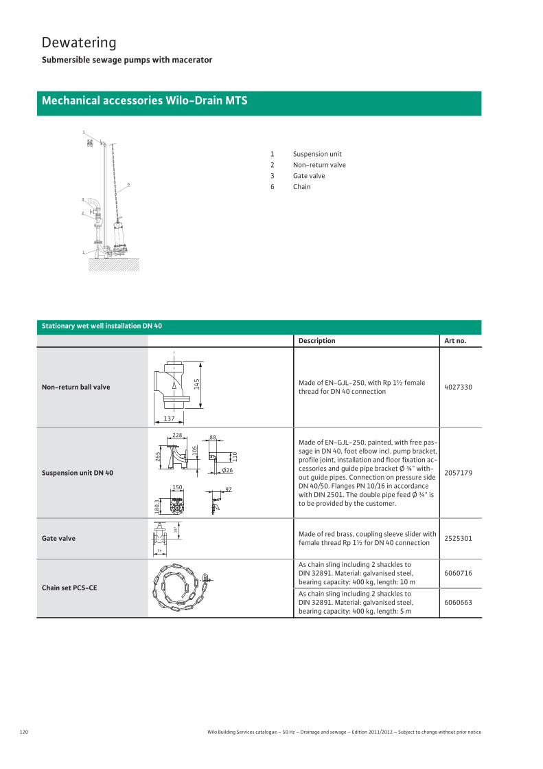
120 Wilo Building Services catalogue – 50 Hz – Drainage and sewage – Edition 2011/2012 – Subject to change without prior notice
DewateringSubmersible sewage pumps with macerator
Mechanical accessories Wilo-Drain MTS
1
3
2
1
6
1 Suspension unit2 Non-return valve3 Gate valve6 Chain
Stationary wet well installation DN 40
Description Art no.
Non-return ball valve Made of EN-GJL-250, with Rp 1½ female thread for DN 40 connection 4027330
Suspension unit DN 40
Made of EN-GJL-250, painted, with free pas-sage in DN 40, foot elbow incl. pump bracket, profile joint, installation and floor fixation ac-cessories and guide pipe bracket Ø ¾" with-out guide pipes. Connection on pressure side DN 40/50. Flanges PN 10/16 in accordance with DIN 2501. The double pipe feed Ø ¾" is to be provided by the customer.
2057179
Gate valve Made of red brass, coupling sleeve slider with female thread Rp 1½ for DN 40 connection 2525301
Chain set PCS-CE
As chain sling including 2 shackles to DIN 32891. Material: galvanised steel, bearing capacity: 400 kg, length: 10 m
6060716
As chain sling including 2 shackles to DIN 32891. Material: galvanised steel, bearing capacity: 400 kg, length: 5 m
6060663
145
137
105
228
265
88
110
Ø26
150
180,
3
97
54
107
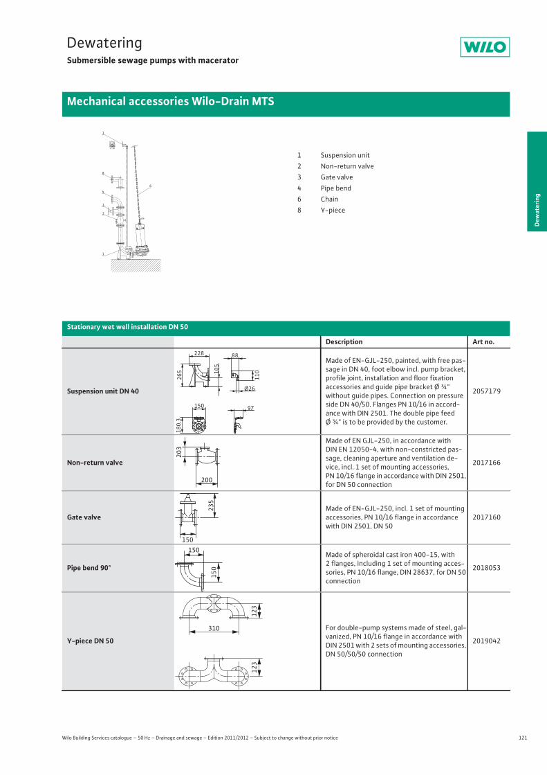
121
DewateringSubmersible sewage pumps with macerator
Dew
ater
ing
Mechanical accessories Wilo-Drain MTS
Wilo Building Services catalogue – 50 Hz – Drainage and sewage – Edition 2011/2012 – Subject to change without prior notice
1
3
2
4
1
8
6
1 Suspension unit2 Non-return valve3 Gate valve4 Pipe bend6 Chain8 Y-piece
Stationary wet well installation DN 50
Description Art no.
Suspension unit DN 40
Made of EN-GJL-250, painted, with free pas-sage in DN 40, foot elbow incl. pump bracket, profile joint, installation and floor fixationaccessories and guide pipe bracket Ø ¾" without guide pipes. Connection on pressure side DN 40/50. Flanges PN 10/16 in accord-ance with DIN 2501. The double pipe feedØ ¾" is to be provided by the customer.
2057179
Non-return valve
Made of EN GJL-250, in accordance withDIN EN 12050-4, with non-constricted pas-sage, cleaning aperture and ventilation de-vice, incl. 1 set of mounting accessories,PN 10/16 flange in accordance with DIN 2501, for DN 50 connection
2017166
Gate valveMade of EN-GJL-250, incl. 1 set of mounting accessories, PN 10/16 flange in accordance with DIN 2501, DN 50
2017160
Pipe bend 90°
Made of spheroidal cast iron 400-15, with2 flanges, including 1 set of mounting acces-sories, PN 10/16 flange, DIN 28637, for DN 50 connection
2018053
Y-piece DN 50
For double-pump systems made of steel, gal-vanized, PN 10/16 flange in accordance with DIN 2501 with 2 sets of mounting accessories, DN 50/50/50 connection
2019042
105
228
265
88
110
Ø26
150
180,
3
97
203
200
150
235
150
150
123
123
310
122 Wilo Building Services catalogue – 50 Hz – Drainage and sewage – Edition 2011/2012 – Subject to change without prior notice
DewateringSubmersible sewage pumps with macerator
Mechanical accessories Wilo-Drain MTS
Chain set PCS-CE
As chain sling including 2 shackles to DIN 32891. Material: galvanised steel, bearing capacity: 400 kg, length: 5 m
6060663
As chain sling including 2 shackles to DIN 32891. Material: galvanised steel, bearing capacity: 400 kg, length: 10 m
6060716
Stationary wet well installation DN 50
Description Art no.
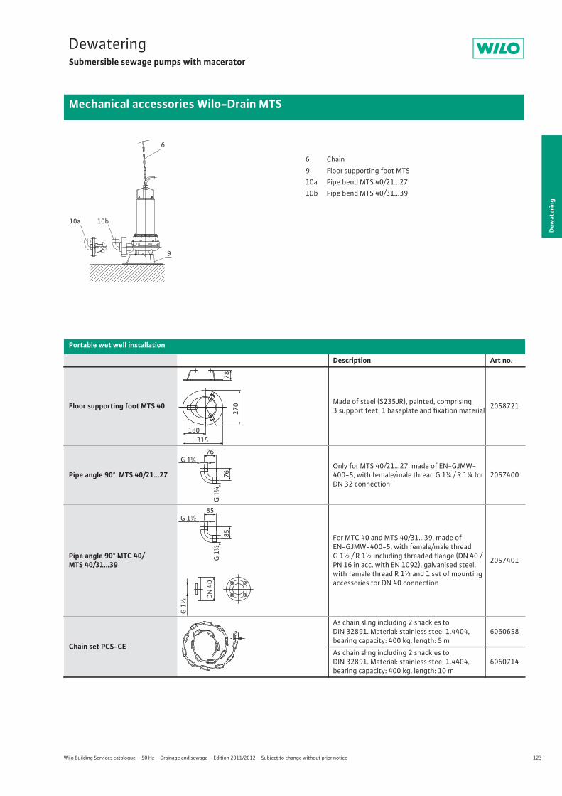
123
DewateringSubmersible sewage pumps with macerator
Dew
ater
ing
Mechanical accessories Wilo-Drain MTS
Wilo Building Services catalogue – 50 Hz – Drainage and sewage – Edition 2011/2012 – Subject to change without prior notice
Portable wet well installation
Description Art no.
Floor supporting foot MTS 40 Made of steel (S235JR), painted, comprising 3 support feet, 1 baseplate and fixation material 2058721
Pipe angle 90° MTS 40/21...27Only for MTS 40/21...27, made of EN-GJMW-400-5, with female/male thread G 1¼ / R 1¼ for DN 32 connection
2057400
Pipe angle 90° MTC 40/MTS 40/31...39
For MTC 40 and MTS 40/31...39, made of EN-GJMW-400-5, with female/male thread G 1½ / R 1½ including threaded flange (DN 40 / PN 16 in acc. with EN 1092), galvanised steel, with female thread R 1½ and 1 set of mounting accessories for DN 40 connection
2057401
Chain set PCS-CE
As chain sling including 2 shackles to DIN 32891. Material: stainless steel 1.4404, bearing capacity: 400 kg, length: 5 m
6060658
As chain sling including 2 shackles to DIN 32891. Material: stainless steel 1.4404, bearing capacity: 400 kg, length: 10 m
6060714
6
10b
9
10a
6 Chain9 Floor supporting foot MTS10a Pipe bend MTS 40/21...2710b Pipe bend MTS 40/31...39
270
78
315180
G 1¼
G 1
¼
76
76
G 1½
G 1
½
G 1
½
DN
40
85
85
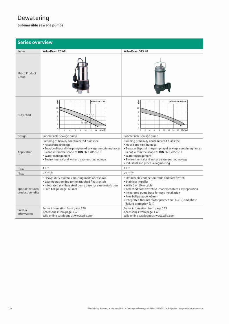
124 Wilo Building Services catalogue – 50 Hz – Drainage and sewage – Edition 2011/2012 – Subject to change without prior notice
DewateringSubmersible sewage pumps
Series overview
Series Wilo-Drain TC 40 Wilo-Drain STS 40
Photo Product Group
Duty chart
Design Submersible sewage pump Submersible sewage pump
Application
Pumping of heavily contaminated fluids for:• House/site drainage• Sewage disposal (the pumping of sewage containing faeces
is not within the scope of DIN EN 12050-1)• Water management• Environmental and water treatment technology
Pumping of heavily contaminated fluids for:• House and site drainage• Sewage disposal (the pumping of sewage containing faeces
is not within the scope of DIN EN 12050-1)• Water management• Environmental and water treatment technology• Industrial and process engineering
Hmax 11 m 10 m
Qmax 22 m3/h 20 m3/h
Special features/product benefits
• Heavy-duty hydraulic housing made of cast iron• Easy operation due to the attached float switch• Integrated stainless steel pump base for easy installation• Free ball passage: 40 mm
• Detachable connection cable and float switch• Stainless impeller• With 5 or 10 m cable• Attached float switch (A-model) enables easy operation• Integrated pump base for easy installation• Free ball passage: 40 mm• Integrated thermal motor protection (1~/3~) and phasefailure protection (3~)
Furtherinformation
Series information from page 128 Accessories from page 132Wilo online catalogue at www.wilo.com
Series information from page 133 Accessories from page 137Wilo online catalogue at www.wilo.com
H[m
]
Q[m³/h]00 2 4 6 8 10 12 14
4
8
10
6
2
Wilo-Drain TC 40
TC 40/8
TC 40/10
H[m]
0
2
4
6
8
10
Q[m³/h]420 10 12 14 1686
Wilo-Drain STS 40
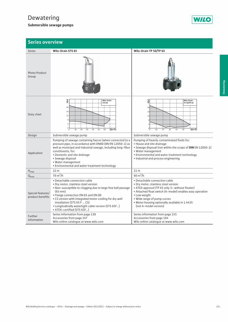
125
DewateringSubmersible sewage pumps
Wilo Building Services catalogue – 50 Hz – Drainage and sewage – Edition 2011/2012 – Subject to change without prior notice
Series overview
Dew
ater
ing
Series Wilo-Drain STS 65 Wilo-Drain TP 50/TP 65
Photo Product Group
Duty chart
Design Submersible sewage pump Submersible sewage pump
Application
Pumping of sewage containing faeces (when connected to a pressure pipe, in accordance with DN80 DIN EN 12050-1) as well as municipal and industrial sewage, including long-fibre constituents, for:• Domestic and site drainage• Sewage disposal• Water management• Environmental and water treatment technology
Pumping of heavily contaminated fluids for:• House and site drainage• Sewage disposal (not within the scope of DIN EN 12050-1)• Water management• Environmental and water treatment technology• Industrial and process engineering
Hmax 22 m 21 m
Qmax 70 m3/h 60 m3/h
Special features/product benefits
• Detachable connection cable• Dry motor, stainless steel version• Non-susceptible to clogging due to large free ball passage
(65 mm)• Flange connection DN 65 and DN 80• CS version with integrated motor cooling for dry well
installation (STS 65 F ... CS)• Longitudinally watertight cable version (STS 65F…)• ATEX-certified (STS 65F…)
• Detachable connection cable• Dry motor, stainless steel version• ATEX approval (TP 65 only 3~ without floater)• Attached float switch (A-model) enables easy operation• Low weight• Wide range of pump curves• Motor housing optionally available in 1.4435
(not A-model version)
Furtherinformation
Series information from page 138Accessories from page 147Wilo online catalogue at www.wilo.com
Series information from page 155Accessories from page 164Wilo online catalogue at www.wilo.com
Q[m³/h]0 10 20 30 40 50 60
H[m
]
0
4
8
12
16
20
Wilo-DrainSTS 65
Q[m³/h]0 10 20 30 40 50
H[m
]
0
4
8
12
16
20
Wilo-DrainTP 50/TP 65
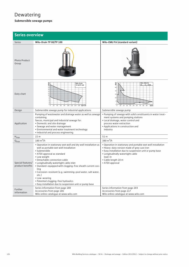
126 Wilo Building Services catalogue – 50 Hz – Drainage and sewage – Edition 2011/2012 – Subject to change without prior notice
DewateringSubmersible sewage pumps
Series overview
Series Wilo-Drain TP 80/TP 100 Wilo-EMU FA (standard variant)
Photo Product Group
Duty chart
Design Submersible sewage pump for industrial applications Submersible sewage pump
Application
Pumping of wastewater and drainage water as well as sewage containingfaeces, municipal and industrial sewage for:• Domestic and site drainage• Sewage and water management• Environmental and water treatment technology• Industrial and process engineering
• Pumping of sewage with solid constituents in water treat-ment systems and pumping stations
• Local drainage, water control andprocess water extraction
• Applications in construction andindustry
Hmax 22 m 51 m
Qmax 180 m3/h 380 m3/h
Special features/product benefits
• Operation in stationary wet well and dry well installation as well as portable wet well installation
• Submersible• ATEX approval as standard• Low weight• Detachable connection cable• Longitudinally watertight cable inlet• Standard-equipped with clogging-free sheath current coo-
ling• Corrosion-resistant (e.g. swimming-pool water, salt water, etc.)
• Low-wearing• Patented clogging-free hydraulics• Easy installation due to suspension unit or pump base
• Operation in stationary and portable wet well installation• Heavy-duty version made of grey cast iron• Easy installation due to suspension unit or pump base• Longitudinally watertight cable
lead-in• Cable length 10 m• ATEX approval
Further information
Series information from page 180 Accessories from page 186Wilo online catalogue at www.wilo.com
Series information from page 203 Accessories from page 217Wilo online catalogue at www.wilo.com
Q[m³/h]0 20 40 60 80 100 120 140 160
H[m]
02468
101214161820
Wilo-DrainTP 80/TP 100
0 10 20 30 40 50 60 70 80 90 Q[l/s]
8
16
24
0
40
32
H[m] Wilo-EMU FA
05... - 15... (SVA)
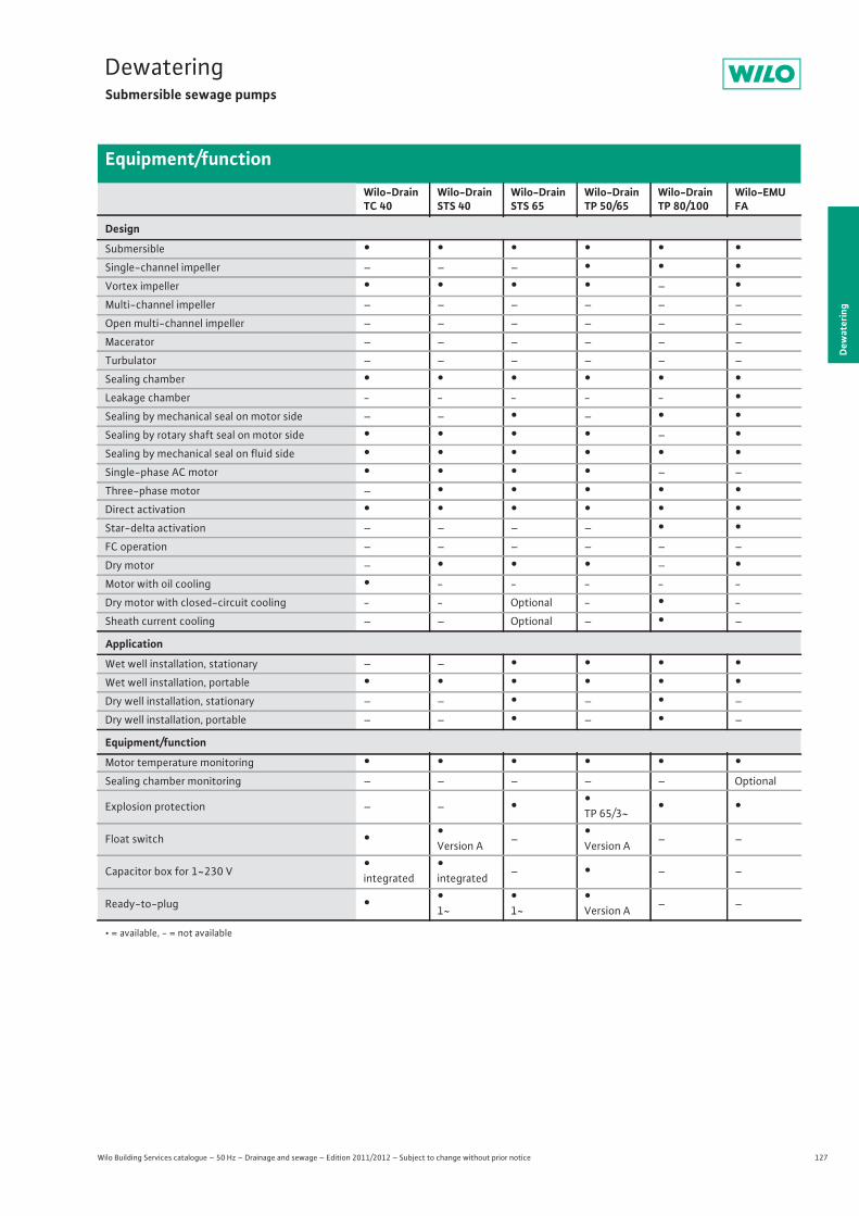
127
DewateringSubmersible sewage pumps
Wilo Building Services catalogue – 50 Hz – Drainage and sewage – Edition 2011/2012 – Subject to change without prior notice
Equipment/function
Dew
ater
ing
Wilo-Drain TC 40
Wilo-Drain STS 40
Wilo-Drain STS 65
Wilo-Drain TP 50/65
Wilo-Drain TP 80/100
Wilo-EMU FA
Design
Submersible • • • • • •Single-channel impeller – – – • • •Vortex impeller • • • • – •Multi-channel impeller – – – – – –
Open multi-channel impeller – – – – – –
Macerator – – – – – –
Turbulator – – – – – –
Sealing chamber • • • • • •Leakage chamber - - - - - •Sealing by mechanical seal on motor side – – • – • •Sealing by rotary shaft seal on motor side • • • • – •Sealing by mechanical seal on fluid side • • • • • •Single-phase AC motor • • • • – –
Three-phase motor – • • • • •Direct activation • • • • • •Star-delta activation – – – – • •FC operation – – – – – –
Dry motor – • • • – •Motor with oil cooling • - - - - -
Dry motor with closed-circuit cooling - - Optional - • -
Sheath current cooling – – Optional – • –
Application
Wet well installation, stationary – – • • • •Wet well installation, portable • • • • • •Dry well installation, stationary – – • – • –
Dry well installation, portable – – • – • –
Equipment/function
Motor temperature monitoring • • • • • •Sealing chamber monitoring – – – – – Optional
Explosion protection – – • •TP 65/3~ • •
Float switch • •Version A – •
Version A – –
Capacitor box for 1~230 V •integrated
•integrated – • – –
Ready-to-plug • •1~
•1~
•Version A – –
• = available, - = not available
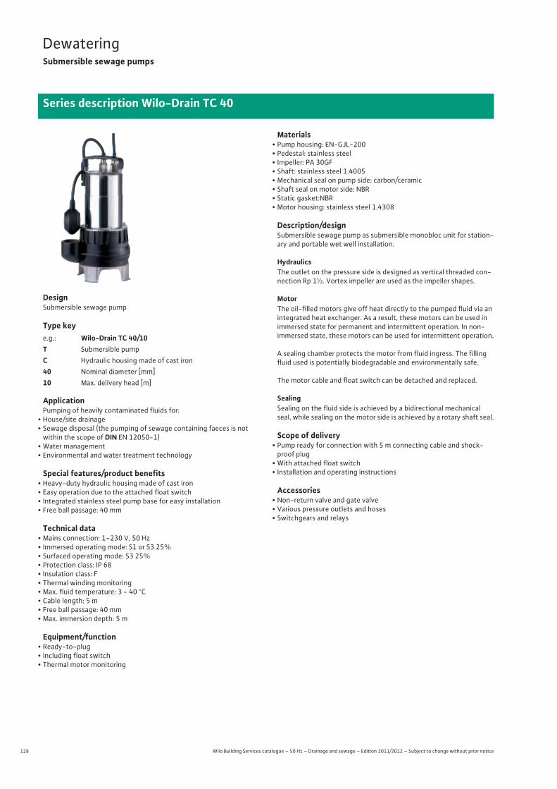
128 Wilo Building Services catalogue – 50 Hz – Drainage and sewage – Edition 2011/2012 – Subject to change without prior notice
DewateringSubmersible sewage pumps
Series description Wilo-Drain TC 40
DesignSubmersible sewage pump
Type key
ApplicationPumping of heavily contaminated fluids for:
• House/site drainage• Sewage disposal (the pumping of sewage containing faeces is not
within the scope of DIN EN 12050-1)• Water management• Environmental and water treatment technology
Special features/product benefits• Heavy-duty hydraulic housing made of cast iron• Easy operation due to the attached float switch• Integrated stainless steel pump base for easy installation• Free ball passage: 40 mm
Technical data• Mains connection: 1~230 V, 50 Hz• Immersed operating mode: S1 or S3 25%• Surfaced operating mode: S3 25%• Protection class: IP 68• Insulation class: F• Thermal winding monitoring• Max. fluid temperature: 3 - 40 °C• Cable length: 5 m• Free ball passage: 40 mm• Max. immersion depth: 5 m
Equipment/function• Ready-to-plug• Including float switch• Thermal motor monitoring
Materials• Pump housing: EN-GJL-200• Pedestal: stainless steel• Impeller: PA 30GF• Shaft: stainless steel 1.4005• Mechanical seal on pump side: carbon/ceramic• Shaft seal on motor side: NBR• Static gasket:NBR• Motor housing: stainless steel 1.4308
Description/designSubmersible sewage pump as submersible monobloc unit for station-ary and portable wet well installation.
HydraulicsThe outlet on the pressure side is designed as vertical threaded con-nection Rp 1½. Vortex impeller are used as the impeller shapes.
MotorThe oil-filled motors give off heat directly to the pumped fluid via an integrated heat exchanger. As a result, these motors can be used in immersed state for permanent and intermittent operation. In non-immersed state, these motors can be used for intermittent operation.
A sealing chamber protects the motor from fluid ingress. The filling fluid used is potentially biodegradable and environmentally safe.
The motor cable and float switch can be detached and replaced.
SealingSealing on the fluid side is achieved by a bidirectional mechanical seal, while sealing on the motor side is achieved by a rotary shaft seal.
Scope of delivery• Pump ready for connection with 5 m connecting cable and shock-proof plug
• With attached float switch• Installation and operating instructions
Accessories• Non-return valve and gate valve• Various pressure outlets and hoses• Switchgears and relays
e.g.: Wilo-Drain TC 40/10T Submersible pumpC Hydraulic housing made of cast iron40 Nominal diameter [mm]10 Max. delivery head [m]
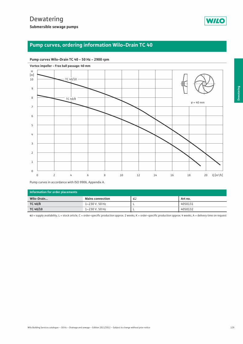
129
DewateringSubmersible sewage pumps
Dew
ater
ing
Pump curves, ordering information Wilo-Drain TC 40
Wilo Building Services catalogue – 50 Hz – Drainage and sewage – Edition 2011/2012 – Subject to change without prior notice
Pump curves Wilo-Drain TC 40 - 50 Hz - 2900 rpm
Vortex impeller - Free ball passage: 40 mm
Pump curves in accordance with ISO 9906, Appendix A.
Information for order placements
Wilo-Drain... Mains connection � Art no.TC 40/8 1~230 V, 50 Hz L 4050131
TC 40/10 1~230 V, 50 Hz L 4050132
�= supply availability, L = stock article, C = order-specific production approx. 2 weeks, K = order-specific production approx. 4 weeks, A = delivery time on request
0
1
2
3
4
5
6
7
8
9
10
H[m]
0 2 4 6 8 10 12 14 16 18 20 Q [m³/h]
ø = 40 mmTC 40/8
TC 40/10
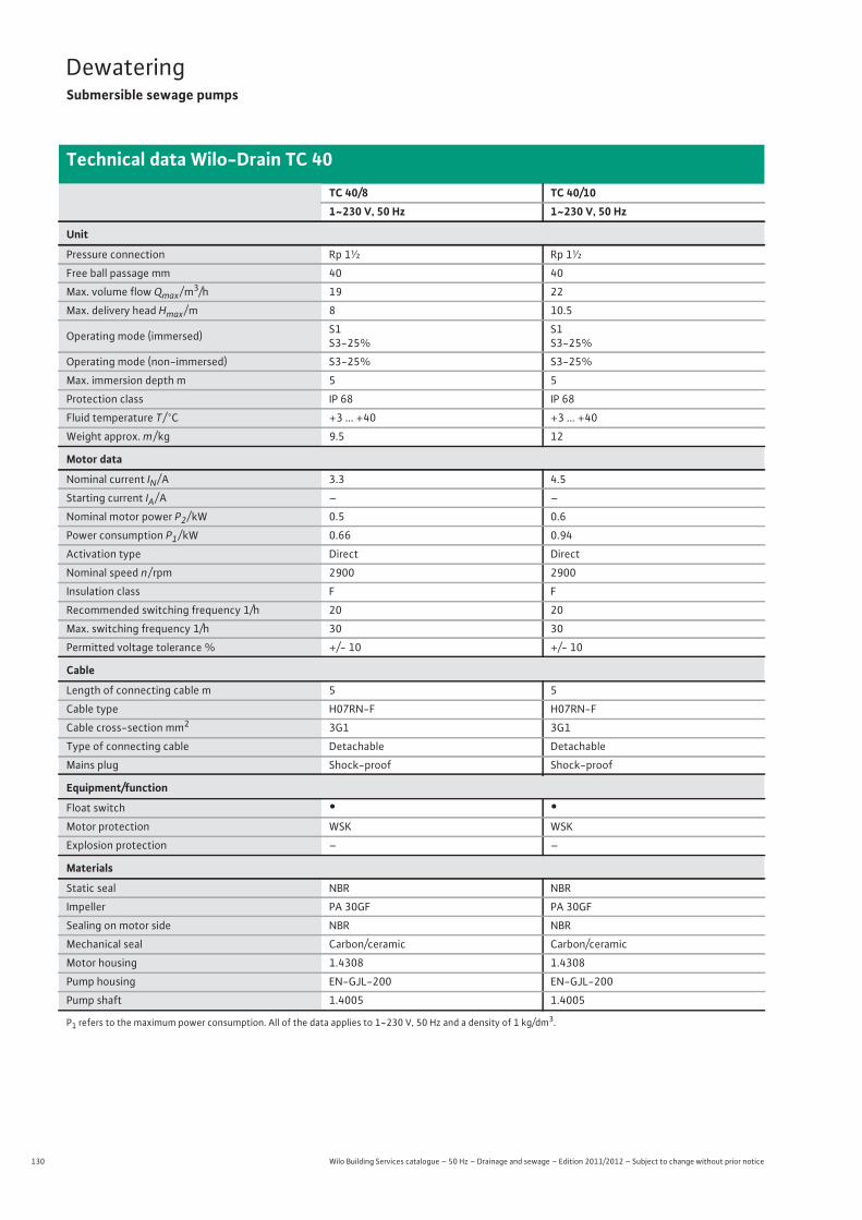
130 Wilo Building Services catalogue – 50 Hz – Drainage and sewage – Edition 2011/2012 – Subject to change without prior notice
DewateringSubmersible sewage pumps
Technical data Wilo-Drain TC 40
TC 40/8 TC 40/101~230 V, 50 Hz 1~230 V, 50 Hz
Unit
Pressure connection Rp 1½ Rp 1½
Free ball passage mm 40 40
Max. volume flow Qmax / m3/h 19 22
Max. delivery head Hmax / m 8 10.5
Operating mode (immersed) S1S3-25%
S1S3-25%
Operating mode (non-immersed) S3-25% S3-25%
Max. immersion depth m 5 5
Protection class IP 68 IP 68
Fluid temperature T / °C +3 ... +40 +3 ... +40
Weight approx. m / kg 9.5 12
Motor data
Nominal current IN / A 3.3 4.5
Starting current IA / A – –
Nominal motor power P2 / kW 0.5 0.6
Power consumption P1 / kW 0.66 0.94
Activation type Direct Direct
Nominal speed n / rpm 2900 2900
Insulation class F F
Recommended switching frequency 1/h 20 20
Max. switching frequency 1/h 30 30
Permitted voltage tolerance % +/- 10 +/- 10
Cable
Length of connecting cable m 5 5
Cable type H07RN-F H07RN-F
Cable cross-section mm2 3G1 3G1
Type of connecting cable Detachable Detachable
Mains plug Shock-proof Shock-proof
Equipment/function
Float switch • •Motor protection WSK WSK
Explosion protection – –
Materials
Static seal NBR NBR
Impeller PA 30GF PA 30GF
Sealing on motor side NBR NBR
Mechanical seal Carbon/ceramic Carbon/ceramic
Motor housing 1.4308 1.4308
Pump housing EN-GJL-200 EN-GJL-200
Pump shaft 1.4005 1.4005
P1 refers to the maximum power consumption. All of the data applies to 1~230 V, 50 Hz and a density of 1 kg/dm3.
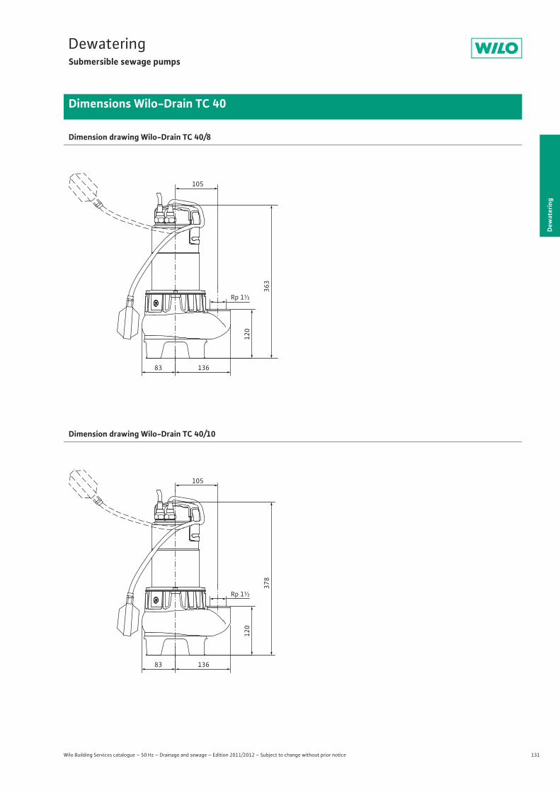
131
DewateringSubmersible sewage pumps
Dew
ater
ing
Dimensions Wilo-Drain TC 40
Wilo Building Services catalogue – 50 Hz – Drainage and sewage – Edition 2011/2012 – Subject to change without prior notice
Dimension drawing Wilo-Drain TC 40/8
Dimension drawing Wilo-Drain TC 40/10
120
13683
363
Rp 1½
105
120
13683
378
Rp 1½
105
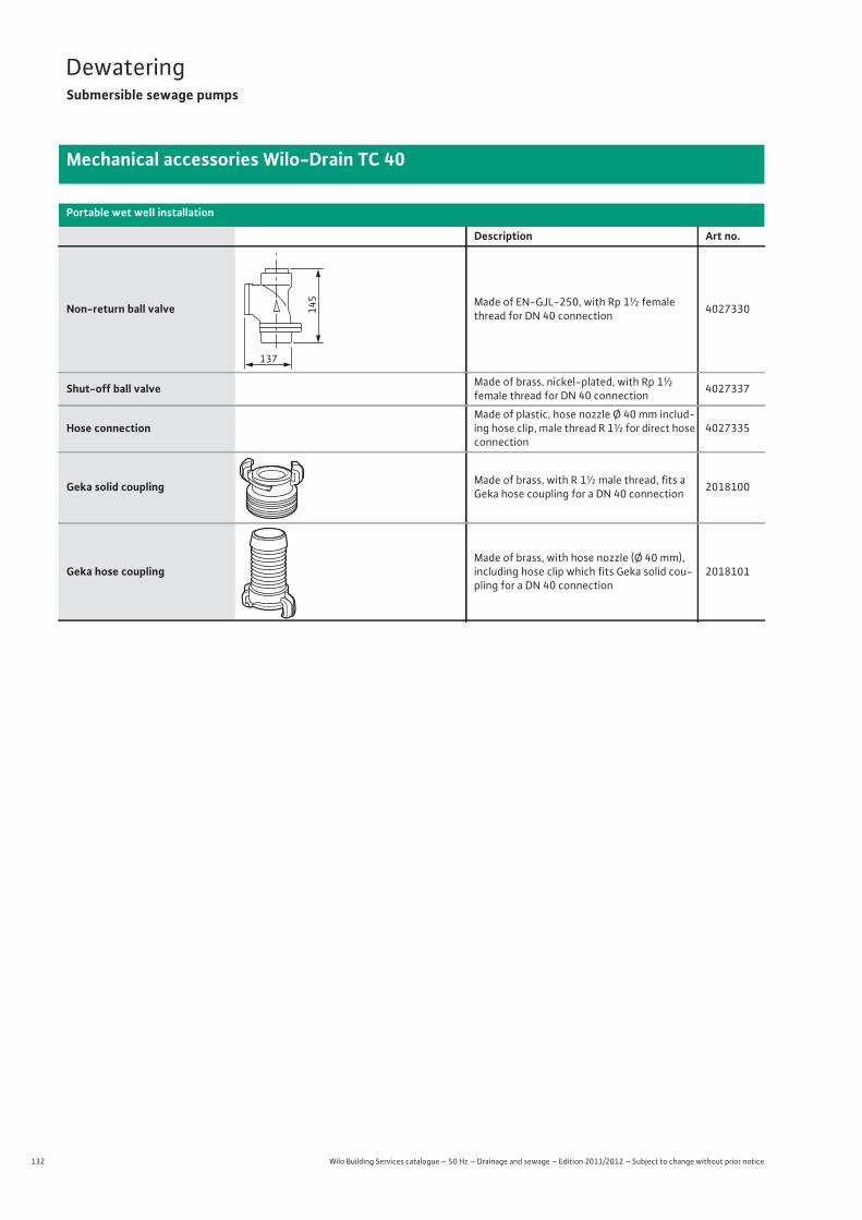
132 Wilo Building Services catalogue – 50 Hz – Drainage and sewage – Edition 2011/2012 – Subject to change without prior notice
DewateringSubmersible sewage pumps
Mechanical accessories Wilo-Drain TC 40
Portable wet well installation
Description Art no.
Non-return ball valve Made of EN-GJL-250, with Rp 1½ female thread for DN 40 connection 4027330
Shut-off ball valve Made of brass, nickel-plated, with Rp 1½female thread for DN 40 connection 4027337
Hose connectionMade of plastic, hose nozzle Ø 40 mm includ-ing hose clip, male thread R 1½ for direct hose connection
4027335
Geka solid coupling Made of brass, with R 1½ male thread, fits a Geka hose coupling for a DN 40 connection 2018100
Geka hose couplingMade of brass, with hose nozzle (Ø 40 mm), including hose clip which fits Geka solid cou-pling for a DN 40 connection
2018101
145
137
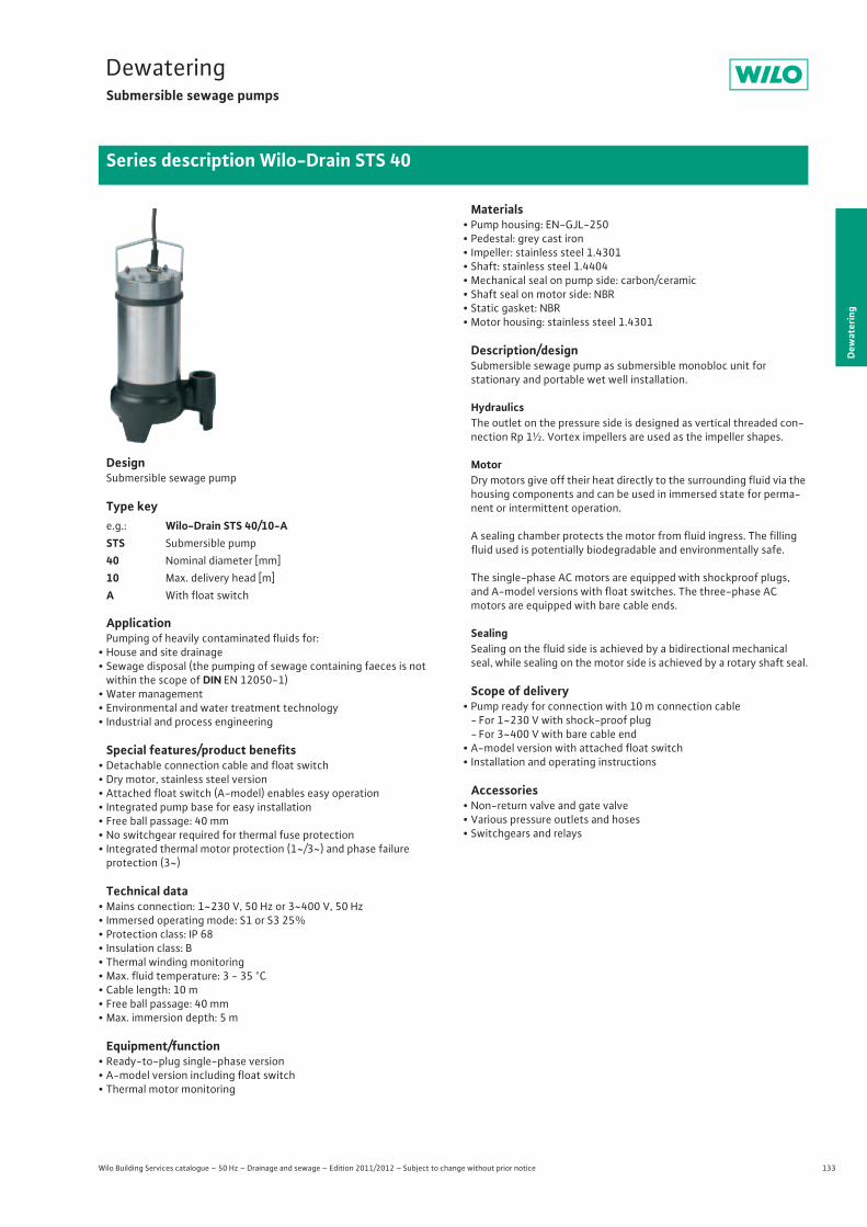
133
DewateringSubmersible sewage pumps
Dew
ater
ing
Series description Wilo-Drain STS 40
Wilo Building Services catalogue – 50 Hz – Drainage and sewage – Edition 2011/2012 – Subject to change without prior notice
DesignSubmersible sewage pump
Type key
ApplicationPumping of heavily contaminated fluids for:
• House and site drainage• Sewage disposal (the pumping of sewage containing faeces is not
within the scope of DIN EN 12050-1)• Water management• Environmental and water treatment technology• Industrial and process engineering
Special features/product benefits• Detachable connection cable and float switch• Dry motor, stainless steel version• Attached float switch (A-model) enables easy operation• Integrated pump base for easy installation• Free ball passage: 40 mm• No switchgear required for thermal fuse protection• Integrated thermal motor protection (1~/3~) and phase failureprotection (3~)
Technical data• Mains connection: 1~230 V, 50 Hz or 3~400 V, 50 Hz• Immersed operating mode: S1 or S3 25%• Protection class: IP 68• Insulation class: B• Thermal winding monitoring• Max. fluid temperature: 3 - 35 °C• Cable length: 10 m• Free ball passage: 40 mm• Max. immersion depth: 5 m
Equipment/function• Ready-to-plug single-phase version• A-model version including float switch• Thermal motor monitoring
Materials• Pump housing: EN-GJL-250• Pedestal: grey cast iron• Impeller: stainless steel 1.4301• Shaft: stainless steel 1.4404• Mechanical seal on pump side: carbon/ceramic• Shaft seal on motor side: NBR• Static gasket: NBR• Motor housing: stainless steel 1.4301
Description/designSubmersible sewage pump as submersible monobloc unit forstationary and portable wet well installation.
HydraulicsThe outlet on the pressure side is designed as vertical threaded con-nection Rp 1½. Vortex impellers are used as the impeller shapes.
MotorDry motors give off their heat directly to the surrounding fluid via the housing components and can be used in immersed state for perma-nent or intermittent operation.
A sealing chamber protects the motor from fluid ingress. The filling fluid used is potentially biodegradable and environmentally safe.
The single-phase AC motors are equipped with shockproof plugs, and A-model versions with float switches. The three-phase ACmotors are equipped with bare cable ends.
SealingSealing on the fluid side is achieved by a bidirectional mechanical seal, while sealing on the motor side is achieved by a rotary shaft seal.
Scope of delivery• Pump ready for connection with 10 m connection cable
- For 1~230 V with shock-proof plug- For 3~400 V with bare cable end
• A-model version with attached float switch• Installation and operating instructions
Accessories• Non-return valve and gate valve• Various pressure outlets and hoses• Switchgears and relays
e.g.: Wilo-Drain STS 40/10-ASTS Submersible pump40 Nominal diameter [mm]10 Max. delivery head [m]A With float switch
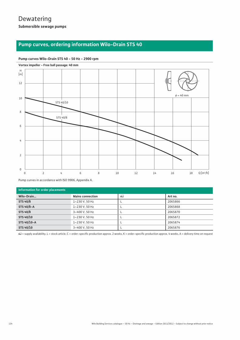
134 Wilo Building Services catalogue – 50 Hz – Drainage and sewage – Edition 2011/2012 – Subject to change without prior notice
DewateringSubmersible sewage pumps
Pump curves, ordering information Wilo-Drain STS 40
Pump curves Wilo-Drain STS 40 - 50 Hz - 2900 rpm
Vortex impeller - Free ball passage: 40 mm
Pump curves in accordance with ISO 9906, Appendix A.
Information for order placements
Wilo-Drain... Mains connection � Art no.STS 40/8 1~230 V, 50 Hz L 2065866
STS 40/8-A 1~230 V, 50 Hz L 2065868
STS 40/8 3~400 V, 50 Hz L 2065870
STS 40/10 1~230 V, 50 Hz L 2065872
STS 40/10-A 1~230 V, 50 Hz L 2065874
STS 40/10 3~400 V, 50 Hz L 2065876
�= supply availability, L = stock article, C = order-specific production approx. 2 weeks, K = order-specific production approx. 4 weeks, A = delivery time on request
H[m]
0
2
4
6
8
10
12
Q [m³/h]42 86 1210 16 18140
ø = 40 mm
STS 40/10
STS 40/8
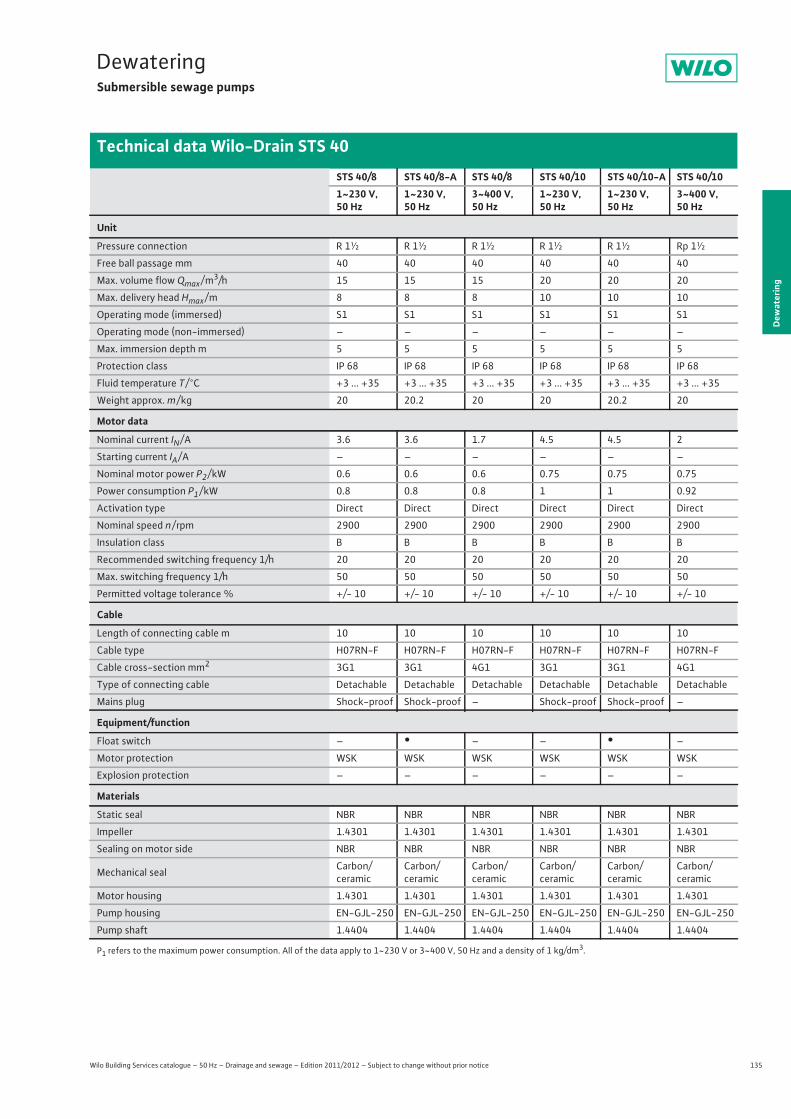
135
DewateringSubmersible sewage pumps
Wilo Building Services catalogue – 50 Hz – Drainage and sewage – Edition 2011/2012 – Subject to change without prior notice
Technical data Wilo-Drain STS 40
Dew
ater
ing
STS 40/8 STS 40/8-A STS 40/8 STS 40/10 STS 40/10-A STS 40/101~230 V, 50 Hz
1~230 V, 50 Hz
3~400 V, 50 Hz
1~230 V, 50 Hz
1~230 V, 50 Hz
3~400 V, 50 Hz
Unit
Pressure connection R 1½ R 1½ R 1½ R 1½ R 1½ Rp 1½
Free ball passage mm 40 40 40 40 40 40
Max. volume flow Qmax / m3/h 15 15 15 20 20 20
Max. delivery head Hmax / m 8 8 8 10 10 10
Operating mode (immersed) S1 S1 S1 S1 S1 S1
Operating mode (non-immersed) – – – – – –
Max. immersion depth m 5 5 5 5 5 5
Protection class IP 68 IP 68 IP 68 IP 68 IP 68 IP 68
Fluid temperature T / °C +3 ... +35 +3 ... +35 +3 ... +35 +3 ... +35 +3 ... +35 +3 ... +35
Weight approx. m / kg 20 20.2 20 20 20.2 20
Motor data
Nominal current IN / A 3.6 3.6 1.7 4.5 4.5 2
Starting current IA / A – – – – – –
Nominal motor power P2 / kW 0.6 0.6 0.6 0.75 0.75 0.75
Power consumption P1 / kW 0.8 0.8 0.8 1 1 0.92
Activation type Direct Direct Direct Direct Direct Direct
Nominal speed n / rpm 2900 2900 2900 2900 2900 2900
Insulation class B B B B B B
Recommended switching frequency 1/h 20 20 20 20 20 20
Max. switching frequency 1/h 50 50 50 50 50 50
Permitted voltage tolerance % +/- 10 +/- 10 +/- 10 +/- 10 +/- 10 +/- 10
Cable
Length of connecting cable m 10 10 10 10 10 10
Cable type H07RN-F H07RN-F H07RN-F H07RN-F H07RN-F H07RN-F
Cable cross-section mm2 3G1 3G1 4G1 3G1 3G1 4G1
Type of connecting cable Detachable Detachable Detachable Detachable Detachable Detachable
Mains plug Shock-proof Shock-proof – Shock-proof Shock-proof –
Equipment/function
Float switch – • – – • –
Motor protection WSK WSK WSK WSK WSK WSK
Explosion protection – – – – – –
Materials
Static seal NBR NBR NBR NBR NBR NBR
Impeller 1.4301 1.4301 1.4301 1.4301 1.4301 1.4301
Sealing on motor side NBR NBR NBR NBR NBR NBR
Mechanical seal Carbon/ceramic
Carbon/ceramic
Carbon/ceramic
Carbon/ceramic
Carbon/ceramic
Carbon/ceramic
Motor housing 1.4301 1.4301 1.4301 1.4301 1.4301 1.4301
Pump housing EN-GJL-250 EN-GJL-250 EN-GJL-250 EN-GJL-250 EN-GJL-250 EN-GJL-250
Pump shaft 1.4404 1.4404 1.4404 1.4404 1.4404 1.4404
P1 refers to the maximum power consumption. All of the data apply to 1~230 V or 3~400 V, 50 Hz and a density of 1 kg/dm3.
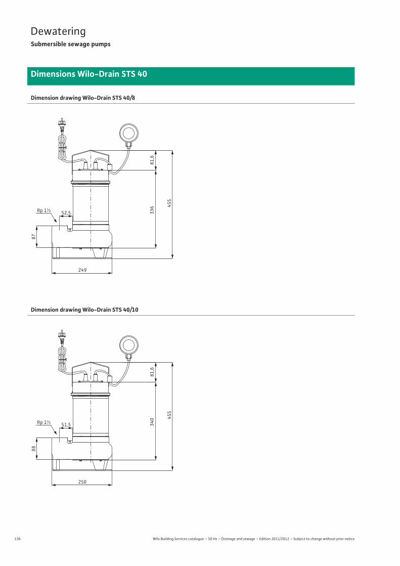
136 Wilo Building Services catalogue – 50 Hz – Drainage and sewage – Edition 2011/2012 – Subject to change without prior notice
DewateringSubmersible sewage pumps
Dimensions Wilo-Drain STS 40
Dimension drawing Wilo-Drain STS 40/8
Dimension drawing Wilo-Drain STS 40/10
249
52,5Rp 1½ 336 45
5
81,6
87
250
51,5Rp 1½ 340 45
5
81,6
88
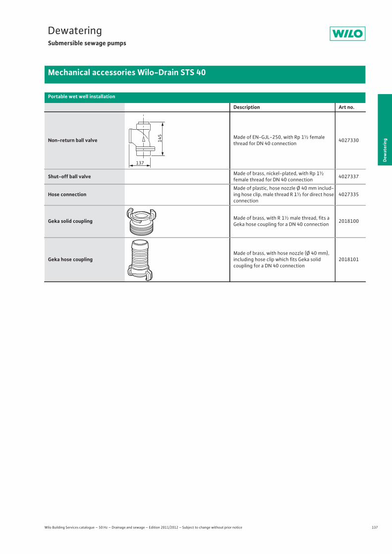
137
DewateringSubmersible sewage pumps
Dew
ater
ing
Mechanical accessories Wilo-Drain STS 40
Wilo Building Services catalogue – 50 Hz – Drainage and sewage – Edition 2011/2012 – Subject to change without prior notice
Portable wet well installation
Description Art no.
Non-return ball valve Made of EN-GJL-250, with Rp 1½ female thread for DN 40 connection 4027330
Shut-off ball valve Made of brass, nickel-plated, with Rp 1½female thread for DN 40 connection 4027337
Hose connectionMade of plastic, hose nozzle Ø 40 mm includ-ing hose clip, male thread R 1½ for direct hose connection
4027335
Geka solid coupling Made of brass, with R 1½ male thread, fits a Geka hose coupling for a DN 40 connection 2018100
Geka hose couplingMade of brass, with hose nozzle (Ø 40 mm), including hose clip which fits Geka solid coupling for a DN 40 connection
2018101
145
137
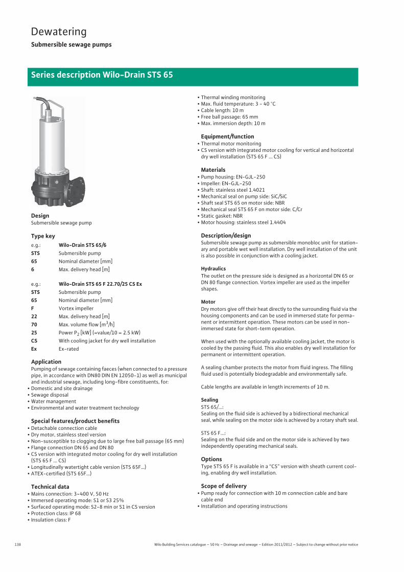
138 Wilo Building Services catalogue – 50 Hz – Drainage and sewage – Edition 2011/2012 – Subject to change without prior notice
DewateringSubmersible sewage pumps
Series description Wilo-Drain STS 65
DesignSubmersible sewage pump
Type key
ApplicationPumping of sewage containing faeces (when connected to a pressure pipe, in accordance with DN80 DIN EN 12050-1) as well as municipal and industrial sewage, including long-fibre constituents, for:
• Domestic and site drainage• Sewage disposal• Water management• Environmental and water treatment technology
Special features/product benefits• Detachable connection cable• Dry motor, stainless steel version• Non-susceptible to clogging due to large free ball passage (65 mm)• Flange connection DN 65 and DN 80• CS version with integrated motor cooling for dry well installation
(STS 65 F ... CS)• Longitudinally watertight cable version (STS 65F…)• ATEX-certified (STS 65F…)
Technical data• Mains connection: 3~400 V, 50 Hz• Immersed operating mode: S1 or S3 25%• Surfaced operating mode: S2-8 min or S1 in CS version• Protection class: IP 68• Insulation class: F
• Thermal winding monitoring• Max. fluid temperature: 3 - 40 °C• Cable length: 10 m• Free ball passage: 65 mm• Max. immersion depth: 10 m
Equipment/function• Thermal motor monitoring• CS version with integrated motor cooling for vertical and horizontal
dry well installation (STS 65 F ... CS)
Materials• Pump housing: EN-GJL-250• Impeller: EN-GJL-250• Shaft: stainless steel 1.4021• Mechanical seal on pump side: SiC/SiC• Shaft seal STS 65 on motor side: NBR• Mechanical seal STS 65 F on motor side: C/Cr• Static gasket: NBR• Motor housing: stainless steel 1.4404
Description/designSubmersible sewage pump as submersible monobloc unit for station-ary and portable wet well installation. Dry well installation of the unit is also possible in conjunction with a cooling jacket.
HydraulicsThe outlet on the pressure side is designed as a horizontal DN 65 or DN 80 flange connection. Vortex impeller are used as the impeller shapes.
MotorDry motors give off their heat directly to the surrounding fluid via the housing components and can be used in immersed state for perma-nent or intermittent operation. These motors can be used in non-immersed state for short-term operation.
When used with the optionally available cooling jacket, the motor is cooled by the passing fluid. This also enables dry well installation for permanent or intermittent operation.
A sealing chamber protects the motor from fluid ingress. The filling fluid used is potentially biodegradable and environmentally safe.
Cable lengths are available in length increments of 10 m.
SealingSTS 65/...:Sealing on the fluid side is achieved by a bidirectional mechanical seal, while sealing on the motor side is achieved by a rotary shaft seal.
STS 65 F...:Sealing on the fluid side and on the motor side is achieved by twoindependently operating mechanical seals.
OptionsType STS 65 F is available in a “CS” version with sheath current cool-ing, enabling dry well installation.
Scope of delivery• Pump ready for connection with 10 m connection cable and barecable end
• Installation and operating instructions
e.g.: Wilo-Drain STS 65/6STS Submersible pump65 Nominal diameter [mm]6 Max. delivery head [m]
e.g.: Wilo-Drain STS 65 F 22.70/25 CS ExSTS Submersible pump65 Nominal diameter [mm]F Vortex impeller22 Max. delivery head [m]70 Max. volume flow [m3/h]25 Power P2 [kW] (=value/10 = 2.5 kW)CS With cooling jacket for dry well installationEx Ex-rated
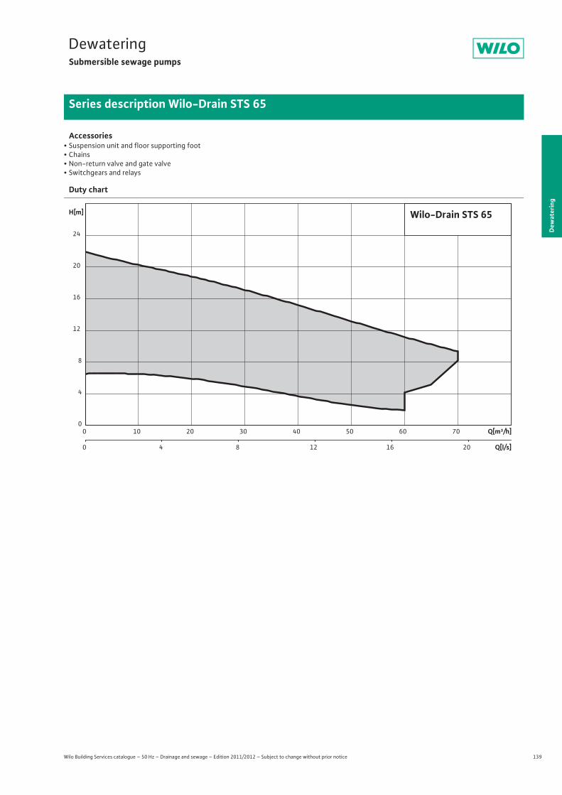
139
DewateringSubmersible sewage pumps
Dew
ater
ing
Series description Wilo-Drain STS 65
Wilo Building Services catalogue – 50 Hz – Drainage and sewage – Edition 2011/2012 – Subject to change without prior notice
Accessories• Suspension unit and floor supporting foot• Chains• Non-return valve and gate valve• Switchgears and relays
Duty chart
Q[m³/h]0 10 20 30 40 50 60 70
Q[l/s]0 4 8 12 16 20
H[m]
0
4
8
12
16
20
24
Wilo-Drain STS 65
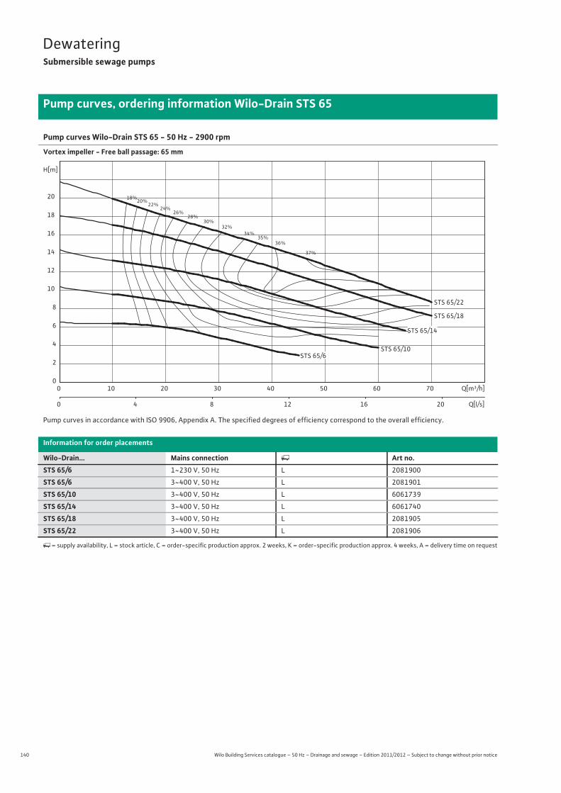
140 Wilo Building Services catalogue – 50 Hz – Drainage and sewage – Edition 2011/2012 – Subject to change without prior notice
DewateringSubmersible sewage pumps
Pump curves, ordering information Wilo-Drain STS 65
Pump curves Wilo-Drain STS 65 - 50 Hz - 2900 rpm
Vortex impeller - Free ball passage: 65 mm
Pump curves in accordance with ISO 9906, Appendix A. The specified degrees of efficiency correspond to the overall efficiency.
Information for order placements
Wilo-Drain... Mains connection � Art no.STS 65/6 1~230 V, 50 Hz L 2081900
STS 65/6 3~400 V, 50 Hz L 2081901
STS 65/10 3~400 V, 50 Hz L 6061739
STS 65/14 3~400 V, 50 Hz L 6061740
STS 65/18 3~400 V, 50 Hz L 2081905
STS 65/22 3~400 V, 50 Hz L 2081906
�= supply availability, L = stock article, C = order-specific production approx. 2 weeks, K = order-specific production approx. 4 weeks, A = delivery time on request
18%20%
22%24%
26%28%
30%32%
34%35%
36%
37%
STS 65/10
STS 65/22
STS 65/18
Q[m³/h]0 10 20 30 40 50 60 70
Q[l/s]0 4 8 12 16 20
H[m]
0
2
4
6
8
10
12
14
16
18
20
STS 65/6
STS 65/14
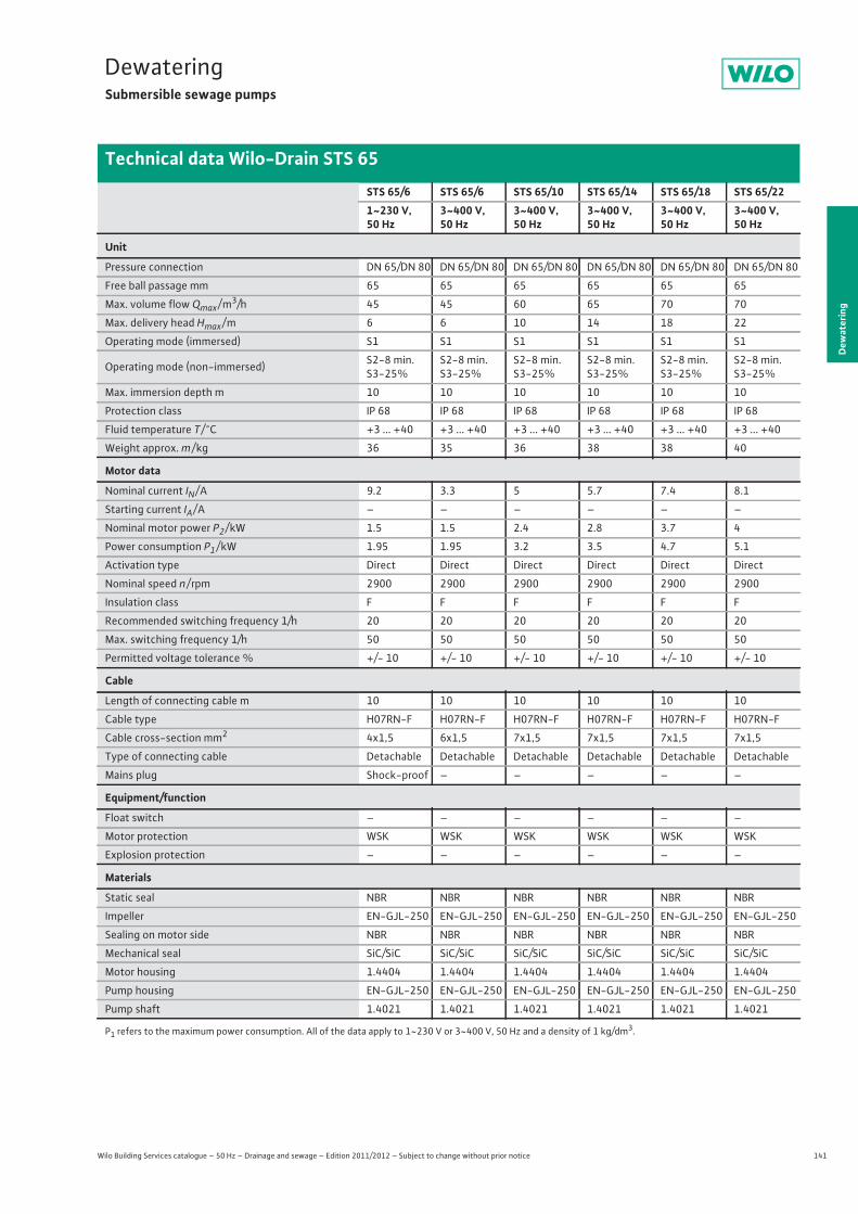
141
DewateringSubmersible sewage pumps
Wilo Building Services catalogue – 50 Hz – Drainage and sewage – Edition 2011/2012 – Subject to change without prior notice
Technical data Wilo-Drain STS 65
Dew
ater
ing
STS 65/6 STS 65/6 STS 65/10 STS 65/14 STS 65/18 STS 65/221~230 V, 50 Hz
3~400 V, 50 Hz
3~400 V, 50 Hz
3~400 V, 50 Hz
3~400 V, 50 Hz
3~400 V, 50 Hz
Unit
Pressure connection DN 65/DN 80 DN 65/DN 80 DN 65/DN 80 DN 65/DN 80 DN 65/DN 80 DN 65/DN 80
Free ball passage mm 65 65 65 65 65 65
Max. volume flow Qmax / m3/h 45 45 60 65 70 70
Max. delivery head Hmax / m 6 6 10 14 18 22
Operating mode (immersed) S1 S1 S1 S1 S1 S1
Operating mode (non-immersed) S2-8 min.S3-25%
S2-8 min.S3-25%
S2-8 min.S3-25%
S2-8 min.S3-25%
S2-8 min.S3-25%
S2-8 min.S3-25%
Max. immersion depth m 10 10 10 10 10 10
Protection class IP 68 IP 68 IP 68 IP 68 IP 68 IP 68
Fluid temperature T / °C +3 ... +40 +3 ... +40 +3 ... +40 +3 ... +40 +3 ... +40 +3 ... +40
Weight approx. m / kg 36 35 36 38 38 40
Motor data
Nominal current IN / A 9.2 3.3 5 5.7 7.4 8.1
Starting current IA / A – – – – – –
Nominal motor power P2 / kW 1.5 1.5 2.4 2.8 3.7 4
Power consumption P1 / kW 1.95 1.95 3.2 3.5 4.7 5.1
Activation type Direct Direct Direct Direct Direct Direct
Nominal speed n / rpm 2900 2900 2900 2900 2900 2900
Insulation class F F F F F F
Recommended switching frequency 1/h 20 20 20 20 20 20
Max. switching frequency 1/h 50 50 50 50 50 50
Permitted voltage tolerance % +/- 10 +/- 10 +/- 10 +/- 10 +/- 10 +/- 10
Cable
Length of connecting cable m 10 10 10 10 10 10
Cable type H07RN-F H07RN-F H07RN-F H07RN-F H07RN-F H07RN-F
Cable cross-section mm2 4x1,5 6x1,5 7x1,5 7x1,5 7x1,5 7x1,5
Type of connecting cable Detachable Detachable Detachable Detachable Detachable Detachable
Mains plug Shock-proof – – – – –
Equipment/function
Float switch – – – – – –
Motor protection WSK WSK WSK WSK WSK WSK
Explosion protection – – – – – –
Materials
Static seal NBR NBR NBR NBR NBR NBR
Impeller EN-GJL-250 EN-GJL-250 EN-GJL-250 EN-GJL-250 EN-GJL-250 EN-GJL-250
Sealing on motor side NBR NBR NBR NBR NBR NBR
Mechanical seal SiC/SiC SiC/SiC SiC/SiC SiC/SiC SiC/SiC SiC/SiC
Motor housing 1.4404 1.4404 1.4404 1.4404 1.4404 1.4404
Pump housing EN-GJL-250 EN-GJL-250 EN-GJL-250 EN-GJL-250 EN-GJL-250 EN-GJL-250
Pump shaft 1.4021 1.4021 1.4021 1.4021 1.4021 1.4021
P1 refers to the maximum power consumption. All of the data apply to 1~230 V or 3~400 V, 50 Hz and a density of 1 kg/dm3.
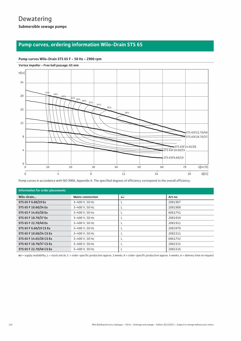
142 Wilo Building Services catalogue – 50 Hz – Drainage and sewage – Edition 2011/2012 – Subject to change without prior notice
DewateringSubmersible sewage pumps
Pump curves, ordering information Wilo-Drain STS 65
Pump curves Wilo-Drain STS 65 F - 50 Hz - 2900 rpm
Vortex impeller - Free ball passage: 65 mm
Pump curves in accordance with ISO 9906, Appendix A. The specified degrees of efficiency correspond to the overall efficiency.
Information for order placements
Wilo-Drain... Mains connection � Art no.STS 65 F 6.60/19 Ex 3~400 V, 50 Hz L 2081907
STS 65 F 10.60/24 Ex 3~400 V, 50 Hz L 2081908
STS 65 F 14.65/28 Ex 3~400 V, 50 Hz L 6061741
STS 65 F 18.70/37 Ex 3~400 V, 50 Hz L 2081910
STS 65 F 22.70/40 Ex 3~400 V, 50 Hz L 2081911
STS 65 F 6.60/19 CS Ex 3~400 V, 50 Hz L 2083970
STS 65 F 10.60/24 CS Ex 3~400 V, 50 Hz L 2082311
STS 65 F 14.65/28 CS Ex 3~400 V, 50 Hz L 6061742
STS 65 F 18.70/37 CS Ex 3~400 V, 50 Hz L 2082315
STS 65 F 22.70/40 CS Ex 3~400 V, 50 Hz L 2082316
�= supply availability, L = stock article, C = order-specific production approx. 2 weeks, K = order-specific production approx. 4 weeks, A = delivery time on request
14%18%
22%26% 28%
30%32%
34%36%
38%
STS 65F22.70/40
STS 65F6.60/19
Q[m³/h]0 10 20 30 40 50 60 70
Q[l/s]0 4 8 12 16 20
H[m]
0
4
8
12
16
20
24
STS 65F14.65/28STS 65F10.60/24
STS 65F18.70/37
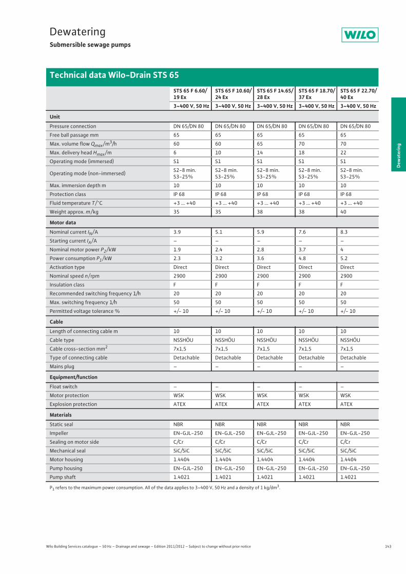
143
DewateringSubmersible sewage pumps
Wilo Building Services catalogue – 50 Hz – Drainage and sewage – Edition 2011/2012 – Subject to change without prior notice
Technical data Wilo-Drain STS 65
Dew
ater
ing
STS 65 F 6.60/19 Ex
STS 65 F 10.60/24 Ex
STS 65 F 14.65/28 Ex
STS 65 F 18.70/37 Ex
STS 65 F 22.70/40 Ex
3~400 V, 50 Hz 3~400 V, 50 Hz 3~400 V, 50 Hz 3~400 V, 50 Hz 3~400 V, 50 Hz
Unit
Pressure connection DN 65/DN 80 DN 65/DN 80 DN 65/DN 80 DN 65/DN 80 DN 65/DN 80
Free ball passage mm 65 65 65 65 65
Max. volume flow Qmax / m3/h 60 60 65 70 70
Max. delivery head Hmax / m 6 10 14 18 22
Operating mode (immersed) S1 S1 S1 S1 S1
Operating mode (non-immersed) S2-8 min.S3-25%
S2-8 min.S3-25%
S2-8 min.S3-25%
S2-8 min.S3-25%
S2-8 min.S3-25%
Max. immersion depth m 10 10 10 10 10
Protection class IP 68 IP 68 IP 68 IP 68 IP 68
Fluid temperature T / °C +3 ... +40 +3 ... +40 +3 ... +40 +3 ... +40 +3 ... +40
Weight approx. m / kg 35 35 38 38 40
Motor data
Nominal current IN / A 3.9 5.1 5.9 7.6 8.3
Starting current IA / A – – – – –
Nominal motor power P2 / kW 1.9 2.4 2.8 3.7 4
Power consumption P1 / kW 2.3 3.2 3.6 4.8 5.2
Activation type Direct Direct Direct Direct Direct
Nominal speed n / rpm 2900 2900 2900 2900 2900
Insulation class F F F F F
Recommended switching frequency 1/h 20 20 20 20 20
Max. switching frequency 1/h 50 50 50 50 50
Permitted voltage tolerance % +/- 10 +/- 10 +/- 10 +/- 10 +/- 10
Cable
Length of connecting cable m 10 10 10 10 10
Cable type NSSHÖU NSSHÖU NSSHÖU NSSHÖU NSSHÖU
Cable cross-section mm2 7x1,5 7x1,5 7x1,5 7x1,5 7x1,5
Type of connecting cable Detachable Detachable Detachable Detachable Detachable
Mains plug – – – – –
Equipment/function
Float switch – – – – –
Motor protection WSK WSK WSK WSK WSK
Explosion protection ATEX ATEX ATEX ATEX ATEX
Materials
Static seal NBR NBR NBR NBR NBR
Impeller EN-GJL-250 EN-GJL-250 EN-GJL-250 EN-GJL-250 EN-GJL-250
Sealing on motor side C/Cr C/Cr C/Cr C/Cr C/Cr
Mechanical seal SiC/SiC SiC/SiC SiC/SiC SiC/SiC SiC/SiC
Motor housing 1.4404 1.4404 1.4404 1.4404 1.4404
Pump housing EN-GJL-250 EN-GJL-250 EN-GJL-250 EN-GJL-250 EN-GJL-250
Pump shaft 1.4021 1.4021 1.4021 1.4021 1.4021
P1 refers to the maximum power consumption. All of the data applies to 3~400 V, 50 Hz and a density of 1 kg/dm3.
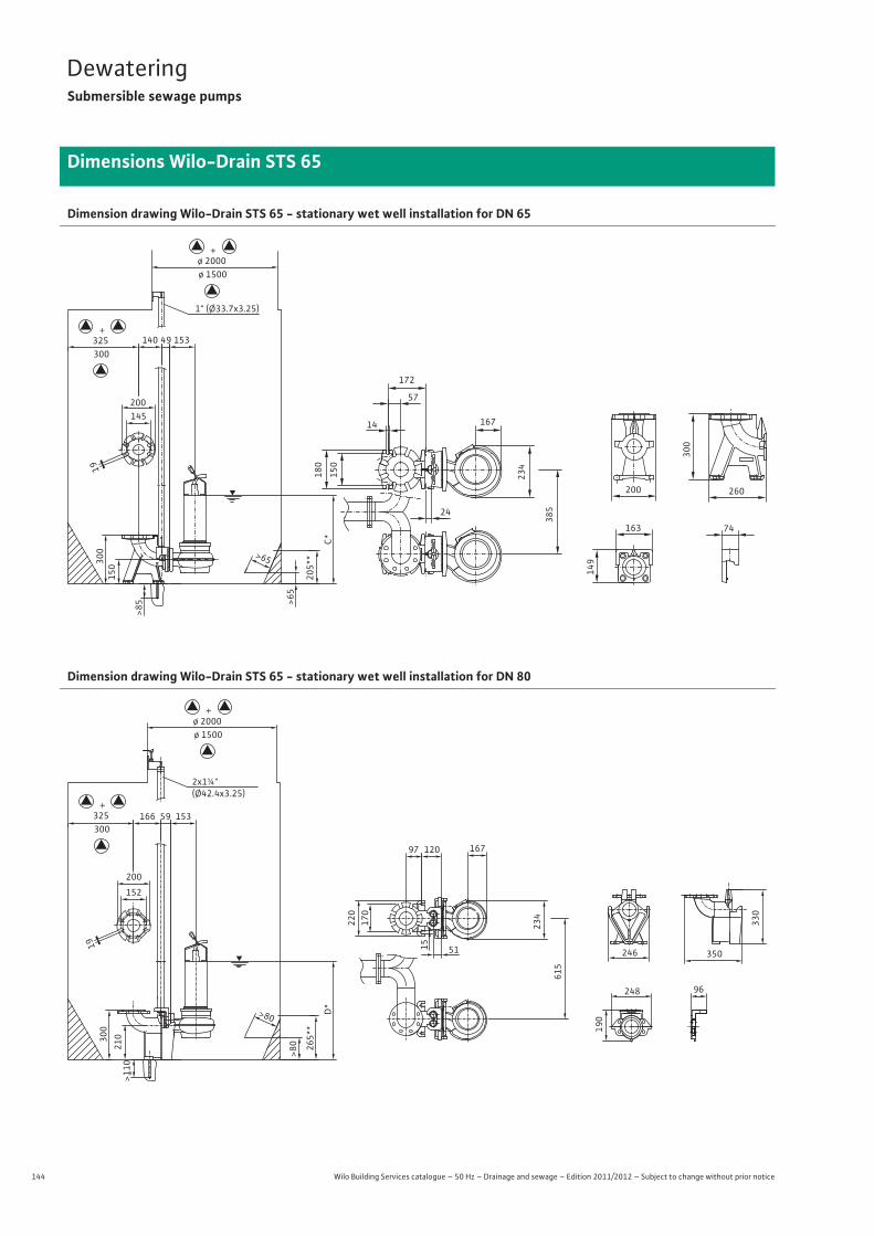
144 Wilo Building Services catalogue – 50 Hz – Drainage and sewage – Edition 2011/2012 – Subject to change without prior notice
DewateringSubmersible sewage pumps
Dimensions Wilo-Drain STS 65
Dimension drawing Wilo-Drain STS 65 - stationary wet well installation for DN 65
Dimension drawing Wilo-Drain STS 65 - stationary wet well installation for DN 80
C*
19
200145
300325
205*
*>65
57
24
385
180
150
167
234
1" (Ø33.7x3.25)
>85 >6
5
140 49 153
15030
0
172
14
74163
149
200 260
300
+
ø 1500ø 2000
+
19
200
152
265*
*
>80
350
330
248
190
96
120
51
615
220
170
167
234
2x1¼"(Ø42.4x3.25)
>110
>80
166 59 153
246
15
210300
97
ø 1500ø 2000
+
300325
+
D*
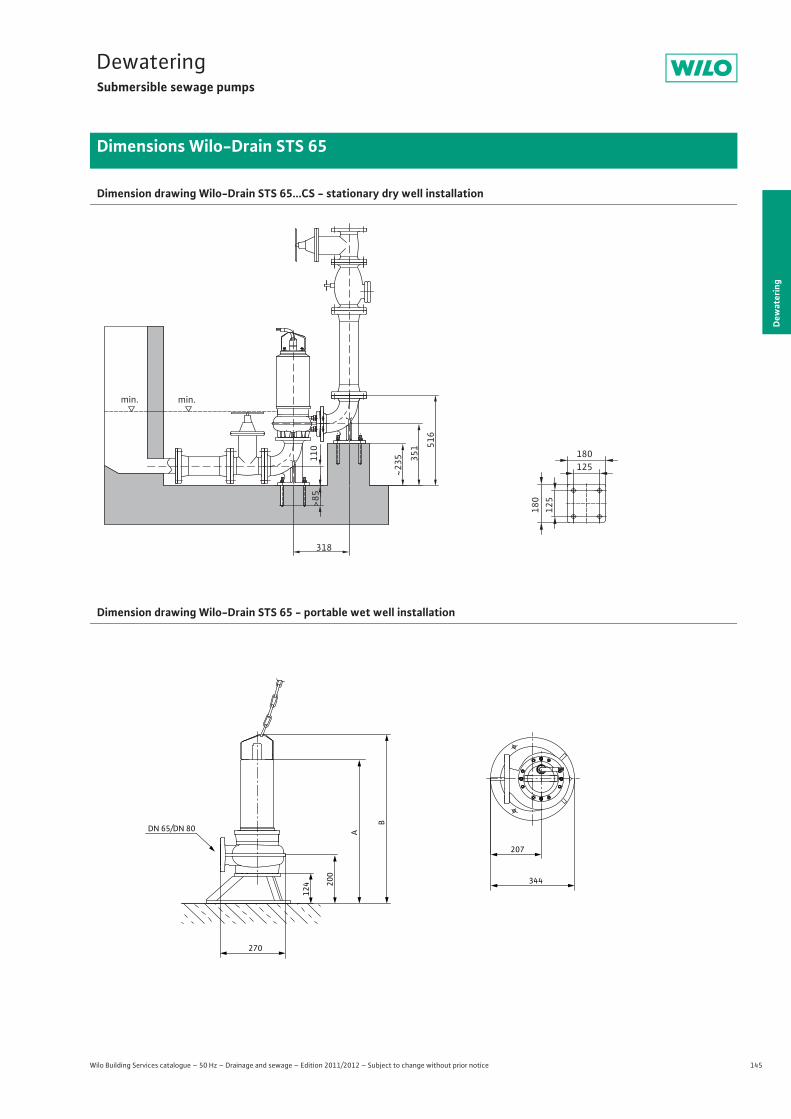
145
DewateringSubmersible sewage pumps
Dew
ater
ing
Dimensions Wilo-Drain STS 65
Wilo Building Services catalogue – 50 Hz – Drainage and sewage – Edition 2011/2012 – Subject to change without prior notice
Dimension drawing Wilo-Drain STS 65...CS - stationary dry well installation
Dimension drawing Wilo-Drain STS 65 - portable wet well installation
min. min.
110
351 51
6
318
180 125
180
125 >85
~235
207
270
DN 65/DN 80
124 20
0
A
B
344
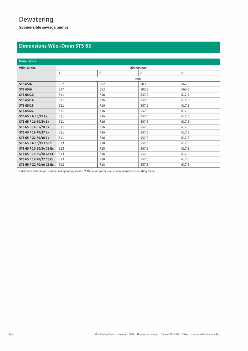
146 Wilo Building Services catalogue – 50 Hz – Drainage and sewage – Edition 2011/2012 – Subject to change without prior notice
DewateringSubmersible sewage pumps
Dimensions Wilo-Drain STS 65
Dimensions
Wilo-Drain... DimensionsA B C D
mm
STS 65/6 557 662 503.5 563.5
STS 65/6 557 662 503.5 563.5
STS 65/10 611 716 557.5 617.5
STS 65/14 611 716 557.5 617.5
STS 65/18 611 716 557.5 617.5
STS 65/22 611 716 557.5 617.5
STS 65 F 6.60/19 Ex 611 716 557.5 617.5
STS 65 F 10.60/24 Ex 611 716 557.5 617.5
STS 65 F 14.65/28 Ex 611 716 557.5 617.5
STS 65 F 18.70/37 Ex 611 716 557.5 617.5
STS 65 F 22.70/40 Ex 611 716 557.5 617.5
STS 65 F 6.60/19 CS Ex 613 718 557.5 617.5
STS 65 F 10.60/24 CS Ex 613 718 557.5 617.5
STS 65 F 14.65/28 CS Ex 613 718 557.5 617.5
STS 65 F 18.70/37 CS Ex 613 718 557.5 617.5
STS 65 F 22.70/40 CS Ex 613 718 557.5 617.5
*Minimum water level in immersed operating mode; ** Minimum water level in non-immersed operating mode
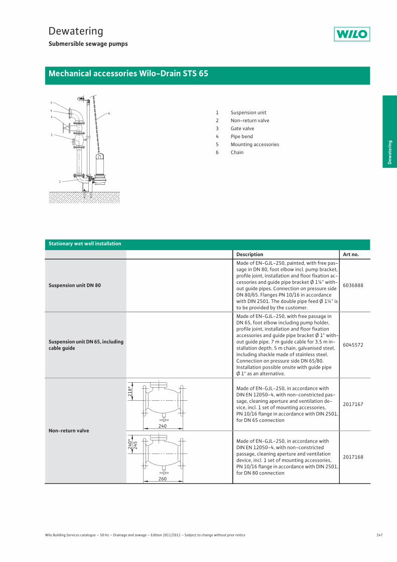
147
DewateringSubmersible sewage pumps
Dew
ater
ing
Mechanical accessories Wilo-Drain STS 65
Wilo Building Services catalogue – 50 Hz – Drainage and sewage – Edition 2011/2012 – Subject to change without prior notice
Stationary wet well installation
Description Art no.
Suspension unit DN 80
Made of EN-GJL-250, painted, with free pas-sage in DN 80, foot elbow incl. pump bracket, profile joint, installation and floor fixation ac-cessories and guide pipe bracket Ø 1¼" with-out guide pipes. Connection on pressure side DN 80/65. Flanges PN 10/16 in accordance with DIN 2501. The double pipe feed Ø 1¼" is to be provided by the customer.
6036888
Suspension unit DN 65, including cable guide
Made of EN-GJL-250, with free passage in DN 65, foot elbow including pump holder, profile joint, installation and floor fixation accessories and guide pipe bracket Ø 1" with-out guide pipe. 7 m guide cable for 3.5 m in-stallation depth. 5 m chain, galvanised steel, including shackle made of stainless steel. Connection on pressure side DN 65/80. Installation possible onsite with guide pipe Ø 1" as an alternative.
6045572
Non-return valve
Made of EN-GJL-250, in accordance with DIN EN 12050-4, with non-constricted pas-sage, cleaning aperture and ventilation de-vice, incl. 1 set of mounting accessories, PN 10/16 flange in accordance with DIN 2501, for DN 65 connection
2017167
Made of EN-GJL-250, in accordance with DIN EN 12050-4, with non-constricted passage, cleaning aperture and ventilation device, incl. 1 set of mounting accessories, PN 10/16 flange in accordance with DIN 2501, for DN 80 connection
2017168
4
5
3
2
1
6 1 Suspension unit2 Non-return valve3 Gate valve4 Pipe bend5 Mounting accessories6 Chain
218*
240
240*
245
260
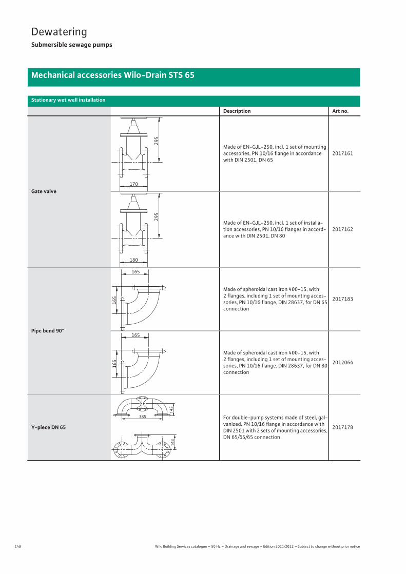
148 Wilo Building Services catalogue – 50 Hz – Drainage and sewage – Edition 2011/2012 – Subject to change without prior notice
DewateringSubmersible sewage pumps
Mechanical accessories Wilo-Drain STS 65
Gate valve
Made of EN-GJL-250, incl. 1 set of mounting accessories, PN 10/16 flange in accordance with DIN 2501, DN 65
2017161
Made of EN-GJL-250, incl. 1 set of installa-tion accessories, PN 10/16 flanges in accord-ance with DIN 2501, DN 80
2017162
Pipe bend 90°
Made of spheroidal cast iron 400-15, with 2 flanges, including 1 set of mounting acces-sories, PN 10/16 flange, DIN 28637, for DN 65 connection
2017183
Made of spheroidal cast iron 400-15, with 2 flanges, including 1 set of mounting acces-sories, PN 10/16 flange, DIN 28637, for DN 80 connection
2012064
Y-piece DN 65
For double-pump systems made of steel, gal-vanized, PN 10/16 flange in accordance with DIN 2501 with 2 sets of mounting accessories, DN 65/65/65 connection
2017178
Stationary wet well installation
Description Art no.
295
170
295
180
165
165
165
165
143
385
143
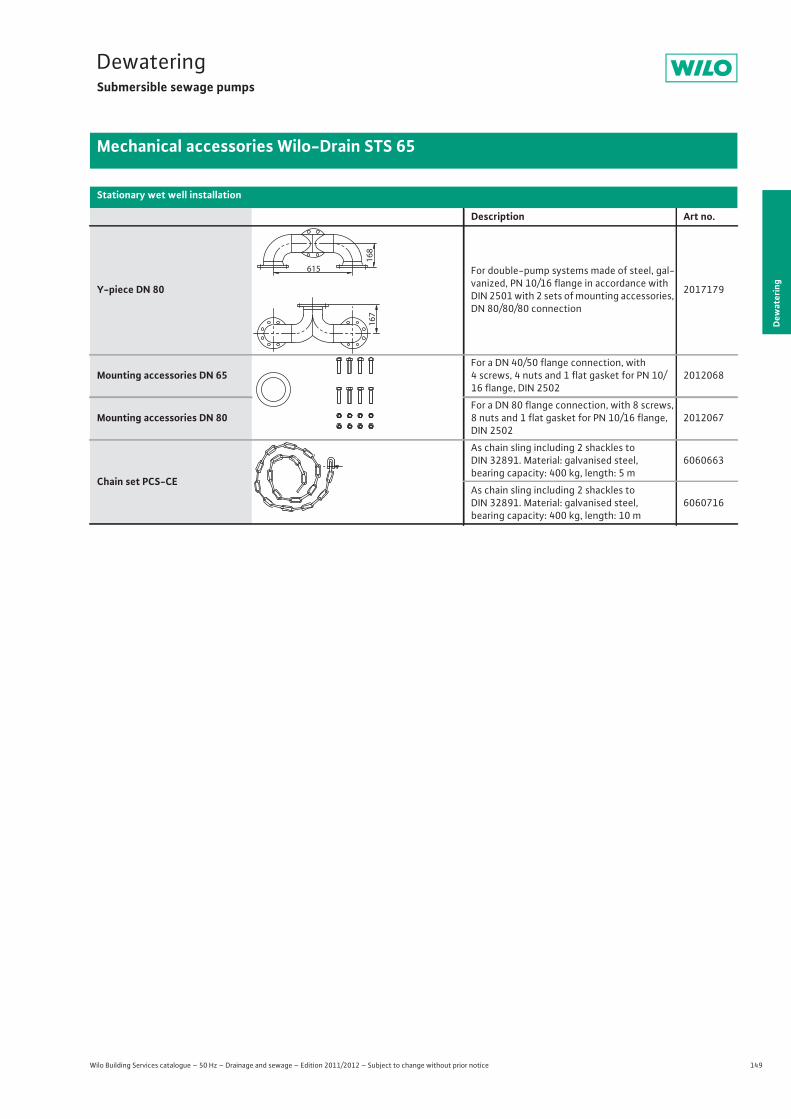
149
DewateringSubmersible sewage pumps
Dew
ater
ing
Mechanical accessories Wilo-Drain STS 65
Wilo Building Services catalogue – 50 Hz – Drainage and sewage – Edition 2011/2012 – Subject to change without prior notice
Y-piece DN 80
For double-pump systems made of steel, gal-vanized, PN 10/16 flange in accordance with DIN 2501 with 2 sets of mounting accessories, DN 80/80/80 connection
2017179
Mounting accessories DN 65For a DN 40/50 flange connection, with 4 screws, 4 nuts and 1 flat gasket for PN 10/16 flange, DIN 2502
2012068
Mounting accessories DN 80For a DN 80 flange connection, with 8 screws, 8 nuts and 1 flat gasket for PN 10/16 flange, DIN 2502
2012067
Chain set PCS-CE
As chain sling including 2 shackles to DIN 32891. Material: galvanised steel, bearing capacity: 400 kg, length: 5 m
6060663
As chain sling including 2 shackles to DIN 32891. Material: galvanised steel, bearing capacity: 400 kg, length: 10 m
6060716
Stationary wet well installation
Description Art no.
167
615
168
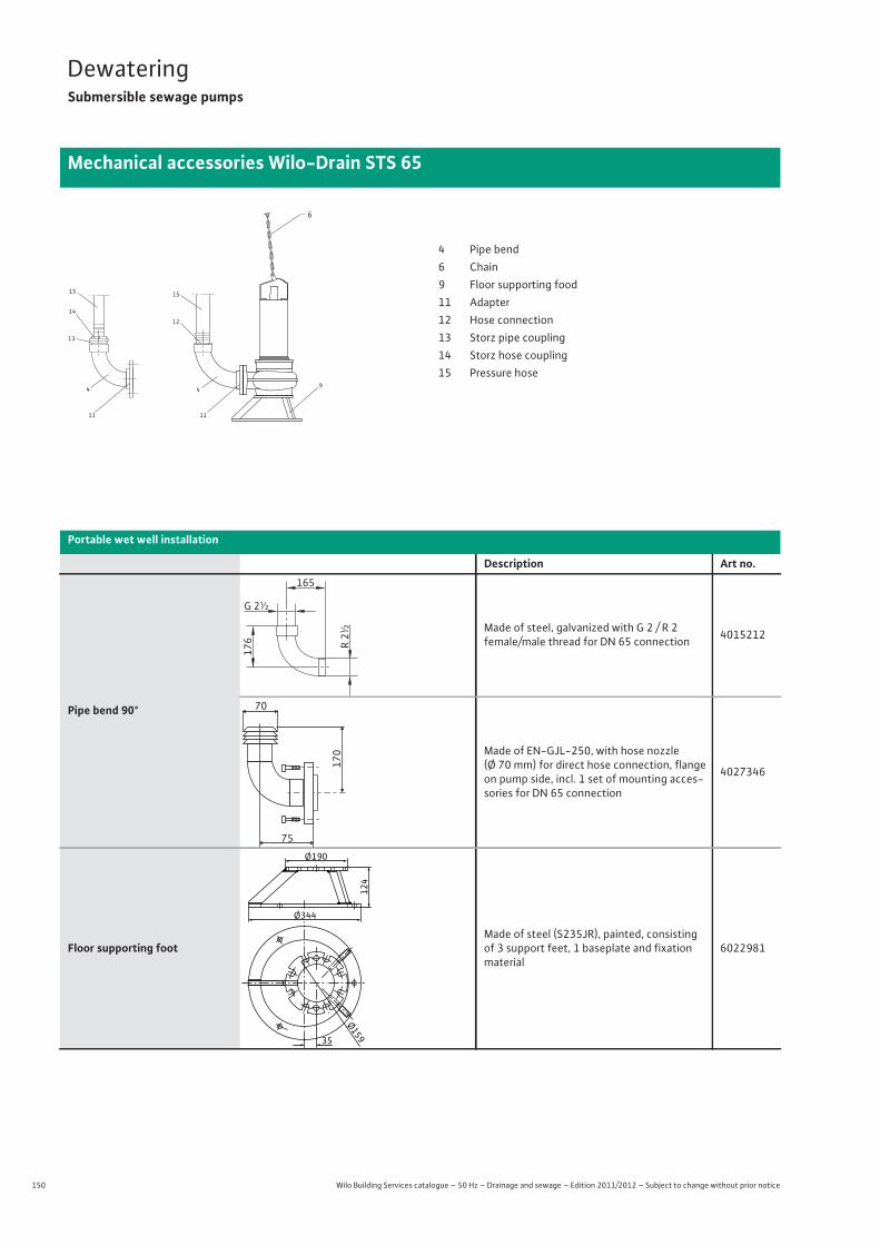
150 Wilo Building Services catalogue – 50 Hz – Drainage and sewage – Edition 2011/2012 – Subject to change without prior notice
DewateringSubmersible sewage pumps
Mechanical accessories Wilo-Drain STS 65
Portable wet well installation
Description Art no.
Pipe bend 90°
Made of steel, galvanized with G 2 / R 2female/male thread for DN 65 connection 4015212
Made of EN-GJL-250, with hose nozzle (Ø 70 mm) for direct hose connection, flange on pump side, incl. 1 set of mounting acces-sories for DN 65 connection
4027346
Floor supporting footMade of steel (S235JR), painted, consisting of 3 support feet, 1 baseplate and fixation material
6022981
6
15
11
15
12
49
11
4
13
14
4 Pipe bend6 Chain9 Floor supporting food11 Adapter12 Hose connection13 Storz pipe coupling14 Storz hose coupling15 Pressure hose
165
G 2½
R 2½
176
70
75
170
Ø159
Ø344
35
Ø190
124
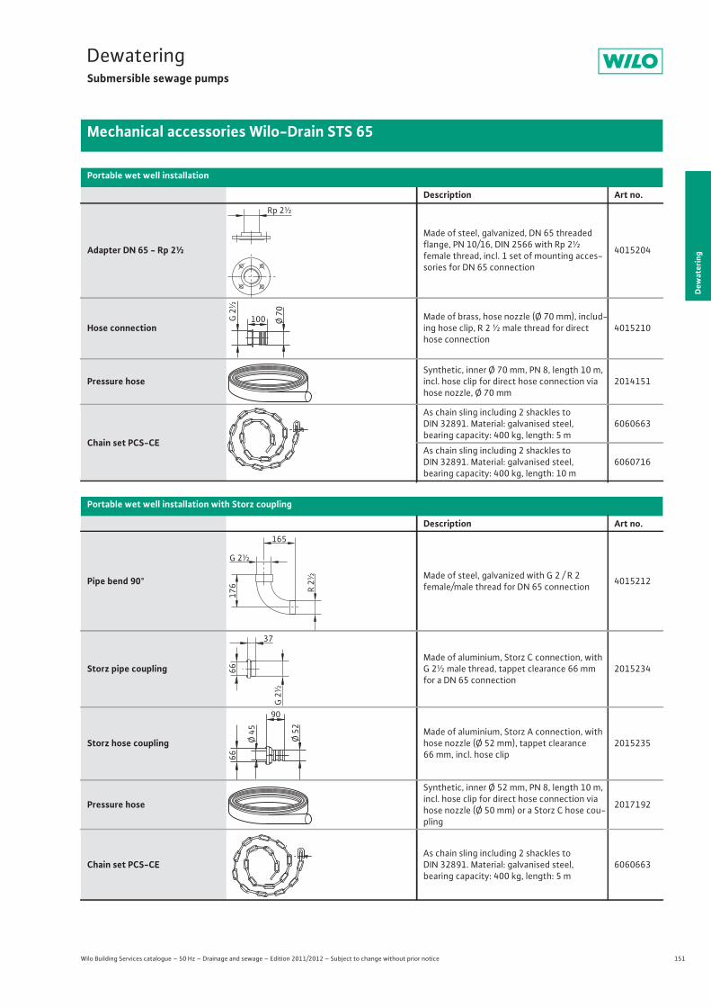
151
DewateringSubmersible sewage pumps
Dew
ater
ing
Mechanical accessories Wilo-Drain STS 65
Wilo Building Services catalogue – 50 Hz – Drainage and sewage – Edition 2011/2012 – Subject to change without prior notice
Adapter DN 65 - Rp 2½
Made of steel, galvanized, DN 65 threaded flange, PN 10/16, DIN 2566 with Rp 2½female thread, incl. 1 set of mounting acces-sories for DN 65 connection
4015204
Hose connectionMade of brass, hose nozzle (Ø 70 mm), includ-ing hose clip, R 2 ½ male thread for direct hose connection
4015210
Pressure hoseSynthetic, inner Ø 70 mm, PN 8, length 10 m, incl. hose clip for direct hose connection via hose nozzle, Ø 70 mm
2014151
Chain set PCS-CE
As chain sling including 2 shackles to DIN 32891. Material: galvanised steel, bearing capacity: 400 kg, length: 5 m
6060663
As chain sling including 2 shackles to DIN 32891. Material: galvanised steel, bearing capacity: 400 kg, length: 10 m
6060716
Portable wet well installation with Storz coupling
Description Art no.
Pipe bend 90° Made of steel, galvanized with G 2 / R 2female/male thread for DN 65 connection 4015212
Storz pipe couplingMade of aluminium, Storz C connection, with G 2½ male thread, tappet clearance 66 mm for a DN 65 connection
2015234
Storz hose couplingMade of aluminium, Storz A connection, with hose nozzle (Ø 52 mm), tappet clearance 66 mm, incl. hose clip
2015235
Pressure hose
Synthetic, inner Ø 52 mm, PN 8, length 10 m, incl. hose clip for direct hose connection via hose nozzle (Ø 50 mm) or a Storz C hose cou-pling
2017192
Chain set PCS-CEAs chain sling including 2 shackles to DIN 32891. Material: galvanised steel, bearing capacity: 400 kg, length: 5 m
6060663
Portable wet well installation
Description Art no.Rp 2½
100 Ø 70
G 2
½
165
G 2½
R 2½
176
G 2
½
37
66
90
Ø 52
66
Ø 45
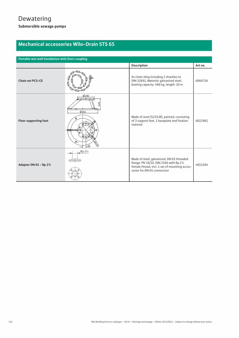
152 Wilo Building Services catalogue – 50 Hz – Drainage and sewage – Edition 2011/2012 – Subject to change without prior notice
DewateringSubmersible sewage pumps
Mechanical accessories Wilo-Drain STS 65
Chain set PCS-CEAs chain sling including 2 shackles to DIN 32891. Material: galvanised steel, bearing capacity: 400 kg, length: 10 m
6060716
Floor supporting footMade of steel (S235JR), painted, consisting of 3 support feet, 1 baseplate and fixation material
6022981
Adapter DN 65 - Rp 2½
Made of steel, galvanized, DN 65 threaded flange, PN 10/16, DIN 2566 with Rp 2½female thread, incl. 1 set of mounting acces-sories for DN 65 connection
4015204
Portable wet well installation with Storz coupling
Description Art no.
Ø159
Ø344
35
Ø19012
4
Rp 2½

153
DewateringSubmersible sewage pumps
Dew
ater
ing
Mechanical accessories Wilo-Drain STS 65
Wilo Building Services catalogue – 50 Hz – Drainage and sewage – Edition 2011/2012 – Subject to change without prior notice
min. min.
2
18183
17
17
2 Non-return valve3 Gate valve17 Installation kit18 Compensator
Stationary vertical dry well installation
Description Art no.
Non-return valve
Made of EN-GJL-250, in accordance with DIN EN 12050-4, with non-constricted pas-sage, cleaning aperture and ventilation de-vice, incl. 1 set of mounting accessories, PN 10/16 flange in accordance with DIN 2501, for DN 80 connection
2017168
Gate valveMade of EN-GJL-250, incl. 1 set of installa-tion accessories, PN 10/16 flanges in accord-ance with DIN 2501, DN 80
2017162
Installation kit STS 65
Made of EN-GJL-250, comprising 2 pipe bends with support (pressure and inlet side), each with 2 flanges for DN 80 connection, in-cl. installation and floor fixation accessories
6042234
240*
245
260
295
180
225
225
494
294
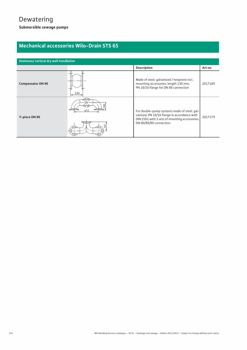
154 Wilo Building Services catalogue – 50 Hz – Drainage and sewage – Edition 2011/2012 – Subject to change without prior notice
DewateringSubmersible sewage pumps
Mechanical accessories Wilo-Drain STS 65
Compensator DN 80Made of steel, galvanized / neoprene incl. mounting accessories, length 130 mm, PN 10/16 flange for DN 80 connection
2017189
Y-piece DN 80
For double-pump systems made of steel, gal-vanized, PN 10/16 flange in accordance with DIN 2501 with 2 sets of mounting accessories, DN 80/80/80 connection
2017179
Stationary vertical dry well installation
Description Art no.
130
167
615
168
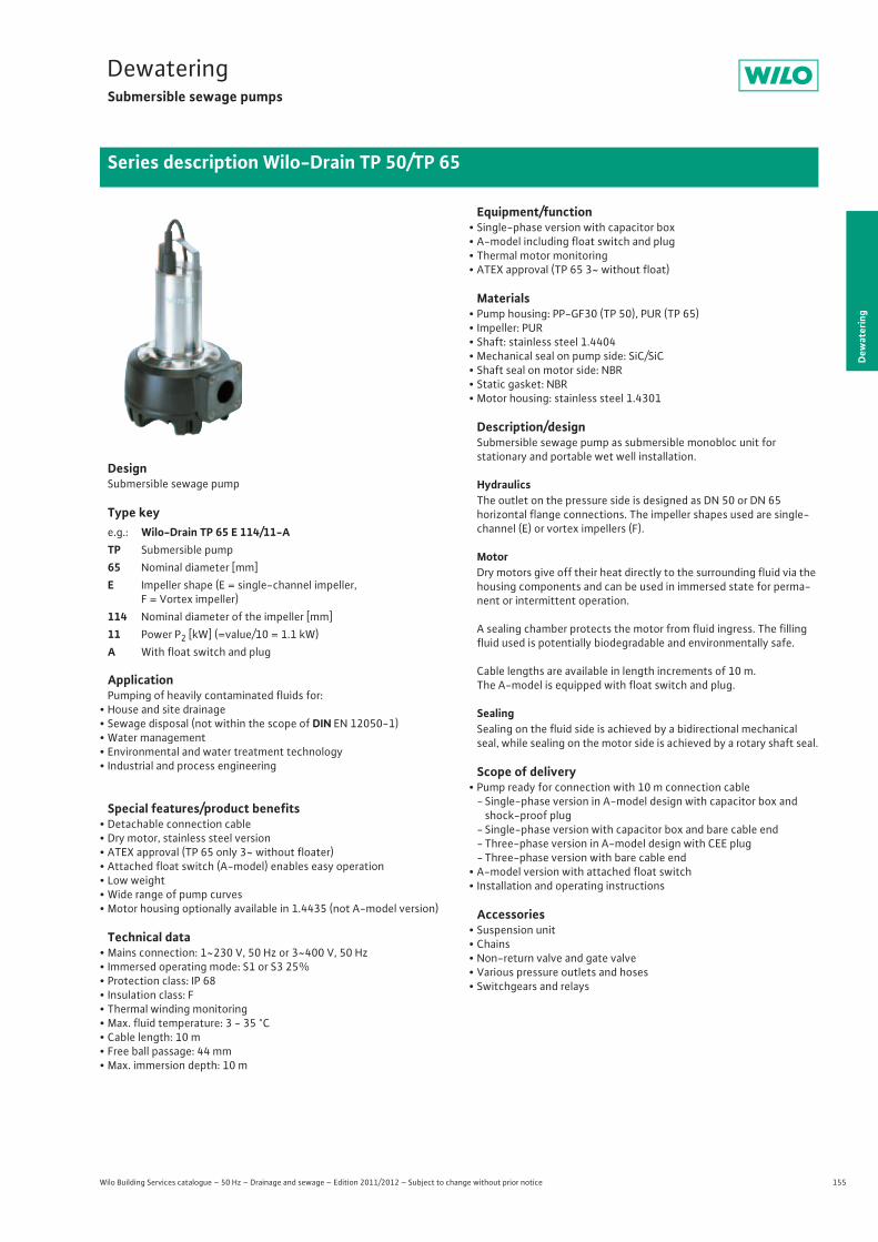
155
DewateringSubmersible sewage pumps
Dew
ater
ing
Series description Wilo-Drain TP 50/TP 65
Wilo Building Services catalogue – 50 Hz – Drainage and sewage – Edition 2011/2012 – Subject to change without prior notice
DesignSubmersible sewage pump
Type key
ApplicationPumping of heavily contaminated fluids for:
• House and site drainage• Sewage disposal (not within the scope of DIN EN 12050-1)• Water management• Environmental and water treatment technology• Industrial and process engineering
Special features/product benefits• Detachable connection cable• Dry motor, stainless steel version• ATEX approval (TP 65 only 3~ without floater)• Attached float switch (A-model) enables easy operation• Low weight• Wide range of pump curves• Motor housing optionally available in 1.4435 (not A-model version)
Technical data• Mains connection: 1~230 V, 50 Hz or 3~400 V, 50 Hz• Immersed operating mode: S1 or S3 25%• Protection class: IP 68• Insulation class: F• Thermal winding monitoring• Max. fluid temperature: 3 - 35 °C• Cable length: 10 m• Free ball passage: 44 mm• Max. immersion depth: 10 m
Equipment/function• Single-phase version with capacitor box• A-model including float switch and plug• Thermal motor monitoring• ATEX approval (TP 65 3~ without float)
Materials• Pump housing: PP-GF30 (TP 50), PUR (TP 65)• Impeller: PUR• Shaft: stainless steel 1.4404• Mechanical seal on pump side: SiC/SiC• Shaft seal on motor side: NBR• Static gasket: NBR• Motor housing: stainless steel 1.4301
Description/designSubmersible sewage pump as submersible monobloc unit forstationary and portable wet well installation.
HydraulicsThe outlet on the pressure side is designed as DN 50 or DN 65horizontal flange connections. The impeller shapes used are single-channel (E) or vortex impellers (F).
MotorDry motors give off their heat directly to the surrounding fluid via the housing components and can be used in immersed state for perma-nent or intermittent operation.
A sealing chamber protects the motor from fluid ingress. The filling fluid used is potentially biodegradable and environmentally safe.
Cable lengths are available in length increments of 10 m.The A-model is equipped with float switch and plug.
SealingSealing on the fluid side is achieved by a bidirectional mechanical seal, while sealing on the motor side is achieved by a rotary shaft seal.
Scope of delivery• Pump ready for connection with 10 m connection cable
- Single-phase version in A-model design with capacitor box and shock-proof plug
- Single-phase version with capacitor box and bare cable end- Three-phase version in A-model design with CEE plug- Three-phase version with bare cable end
• A-model version with attached float switch• Installation and operating instructions
Accessories• Suspension unit• Chains• Non-return valve and gate valve• Various pressure outlets and hoses• Switchgears and relays
e.g.: Wilo-Drain TP 65 E 114/11-ATP Submersible pump65 Nominal diameter [mm]E Impeller shape (E = single-channel impeller,
F = Vortex impeller)114 Nominal diameter of the impeller [mm]11 Power P2 [kW] (=value/10 = 1.1 kW)A With float switch and plug
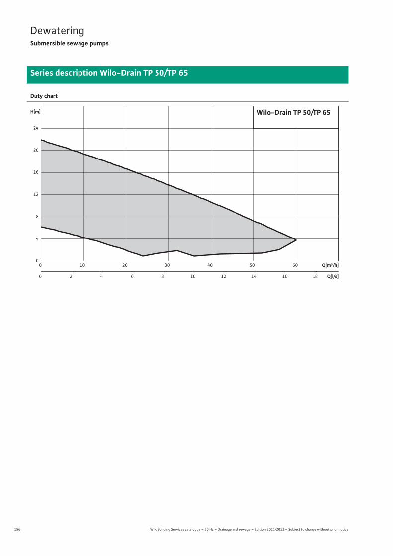
156 Wilo Building Services catalogue – 50 Hz – Drainage and sewage – Edition 2011/2012 – Subject to change without prior notice
DewateringSubmersible sewage pumps
Series description Wilo-Drain TP 50/TP 65
Duty chart
Q[m³/h]0 10 20 30 40 50 60
Q[l/s]0 2 4 6 8 10 12 14 16 18
H[m]
0
4
8
12
16
20
24
Wilo-Drain TP 50/TP 65
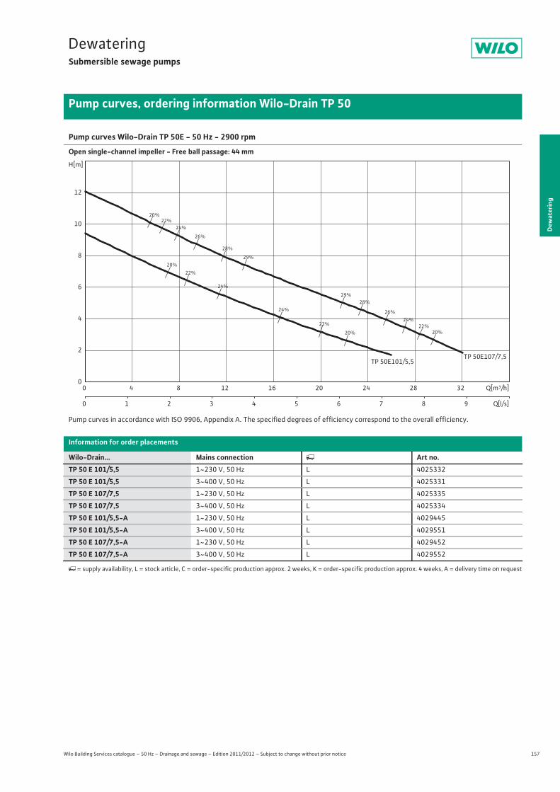
157
DewateringSubmersible sewage pumps
Dew
ater
ing
Pump curves, ordering information Wilo-Drain TP 50
Wilo Building Services catalogue – 50 Hz – Drainage and sewage – Edition 2011/2012 – Subject to change without prior notice
Pump curves Wilo-Drain TP 50E - 50 Hz - 2900 rpm
Open single-channel impeller - Free ball passage: 44 mm
Pump curves in accordance with ISO 9906, Appendix A. The specified degrees of efficiency correspond to the overall efficiency.
Information for order placements
Wilo-Drain... Mains connection � Art no.TP 50 E 101/5,5 1~230 V, 50 Hz L 4025332
TP 50 E 101/5,5 3~400 V, 50 Hz L 4025331
TP 50 E 107/7,5 1~230 V, 50 Hz L 4025335
TP 50 E 107/7,5 3~400 V, 50 Hz L 4025334
TP 50 E 101/5,5-A 1~230 V, 50 Hz L 4029445
TP 50 E 101/5,5-A 3~400 V, 50 Hz L 4029551
TP 50 E 107/7,5-A 1~230 V, 50 Hz L 4029452
TP 50 E 107/7,5-A 3~400 V, 50 Hz L 4029552
�= supply availability, L = stock article, C = order-specific production approx. 2 weeks, K = order-specific production approx. 4 weeks, A = delivery time on request
20%
20%
20%
20%
22%
22%
22%
22%
24%
24%
24%
24%
26%
26%
28%
28%
29%
29%
TP 50E101/5,5TP 50E107/7,5
Q[m³/h]0 4 8 12 16 20 24 28 32
Q[l/s]0 1 2 3 4 5 6 7 8 9
H[m]
0
2
4
6
8
10
12

158 Wilo Building Services catalogue – 50 Hz – Drainage and sewage – Edition 2011/2012 – Subject to change without prior notice
DewateringSubmersible sewage pumps
Technical data Wilo-Drain TP 50
TP 50 E 101/5,5 TP 50 E 101/5,5 TP 50 E 107/7,5 TP 50 E 107/7,51~230 V, 50 Hz 3~400 V, 50 Hz 1~230 V, 50 Hz 3~400 V, 50 Hz
Unit
Pressure connection DN 50 DN 50 DN 50 DN 50
Free ball passage mm 44 44 44 44
Max. volume flow Qmax / m3/h 26 26 32 32
Max. delivery head Hmax / m 9.5 9.5 12 12
Operating mode (immersed) S1S3-25%
S1S3-25%
S1S3-25%
S1S3-25%
Operating mode (non-immersed) S2-8 min.S3-25%
S2-8 min.S3-25%
S2-8 min.S3-25%
S2-8 min.S3-25%
Max. immersion depth m 10 10 10 10
Protection class IP 68 IP 68 IP 68 IP 68
Fluid temperature T / °C +3 ... +35 +3 ... +35 +3 ... +35 +3 ... +35
Weight approx. m / kg 14.5 14.5 16 16
Motor data
Nominal current IN / A 4 2 5.5 2.1
Starting current IA / A – – – –
Nominal motor power P2 / kW 0.55 0.55 0.75 0.75
Power consumption P1 / kW 1 1 1.3 1.1
Activation type Direct Direct Direct Direct
Nominal speed n / rpm 2850 2850 2850 2850
Insulation class F F F F
Recommended switching frequency 1/h 20 20 20 20
Max. switching frequency 1/h 70 70 70 70
Permitted voltage tolerance % +/- 10 +/- 10 +/- 10 +/- 10
Cable
Length of connecting cable m 10 10 10 10
Cable type OZOFLEX (PLUS) 07RNF
OZOFLEX (PLUS) 07RNF
OZOFLEX (PLUS) 07RNF
OZOFLEX (PLUS) 07RNF
Cable cross-section mm2 4G1 6G1 4G1 6G1
Type of connecting cable Detachable Detachable Detachable Detachable
Mains plug – – – –
Equipment/function
Float switch – – – –
Motor protection WSK WSK WSK WSK
Explosion protection – – – –
Materials
Static seal NBR NBR NBR NBR
Impeller PP-GF30 PP-GF30 PP-GF30 PP-GF30
Sealing on motor side NBR NBR NBR NBR
Mechanical seal SiC/SiC SiC/SiC SiC/SiC SiC/SiC
Motor housing 1.4301 1.4301 1.4301 1.4301
Pump housing PP-GF30 PP-GF30 PP-GF30 PP-GF30
Pump shaft 1.4404 1.4404 1.4404 1.4404
P1 refers to the maximum power consumption. All of the data apply to 1~230 V or 3~400 V, 50 Hz and a density of 1 kg/dm3.

159
DewateringSubmersible sewage pumps
Wilo Building Services catalogue – 50 Hz – Drainage and sewage – Edition 2011/2012 – Subject to change without prior notice
Technical data Wilo-Drain TP 50
Dew
ater
ing
TP 50 E 101/5,5-A TP 50 E 101/5,5-A TP 50 E 107/7,5-A TP 50 E 107/7,5-A1~230 V, 50 Hz 3~400 V, 50 Hz 1~230 V, 50 Hz 3~400 V, 50 Hz
Unit
Pressure connection DN 50 DN 50 DN 50 DN 50
Free ball passage mm 44 44 44 44
Max. volume flow Qmax / m3/h 26 26 32 32
Max. delivery head Hmax / m 9.5 9.5 12 12
Operating mode (immersed) S1S3-25%
S1S3-25%
S1S3-25%
S1S3-25%
Operating mode (non-immersed) S2-8 min.S3-25%
S2-8 min.S3-25%
S2-8 min.S3-25%
S2-8 min.S3-25%
Max. immersion depth m 10 10 10 10
Protection class IP 68 IP 68 IP 68 IP 68
Fluid temperature T / °C +3 ... +35 +3 ... +35 +3 ... +35 +3 ... +35
Weight approx. m / kg 14.5 14.5 16 16
Motor data
Nominal current IN / A 4 2 5.5 2.1
Starting current IA / A – – – –
Nominal motor power P2 / kW 0.55 0.55 0.75 0.75
Power consumption P1 / kW 1 1 1.3 1.1
Activation type Direct Direct Direct Direct
Nominal speed n / rpm 2850 2850 2850 2850
Insulation class F F F F
Recommended switching frequency 1/h 20 20 20 20
Max. switching frequency 1/h 70 70 70 70
Permitted voltage tolerance % +/- 10 +/- 10 +/- 10 +/- 10
Cable
Length of connecting cable m 10 10 10 10
Cable type OZOFLEX (PLUS) 07RNF
OZOFLEX (PLUS) 07RNF
OZOFLEX (PLUS) 07RNF
OZOFLEX (PLUS) 07RNF
Cable cross-section mm2 4G1 6G1 4G1 6G1
Type of connecting cable Detachable Detachable Detachable Detachable
Mains plug Shock-proof CEE Shock-proof CEE
Equipment/function
Float switch • • • •Motor protection WSK WSK WSK WSK
Explosion protection – – – –
Materials
Static seal NBR NBR NBR NBR
Impeller PP-GF30 PP-GF30 PP-GF30 PP-GF30
Sealing on motor side NBR NBR NBR NBR
Mechanical seal SiC/SiC SiC/SiC SiC/SiC SiC/SiC
Motor housing 1.4301 1.4301 1.4301 1.4301
Pump housing PP-GF30 PP-GF30 PP-GF30 PP-GF30
Pump shaft 1.4404 1.4404 1.4404 1.4404
P1 refers to the maximum power consumption. All of the data apply to 1~230 V or 3~400 V, 50 Hz and a density of 1 kg/dm3.
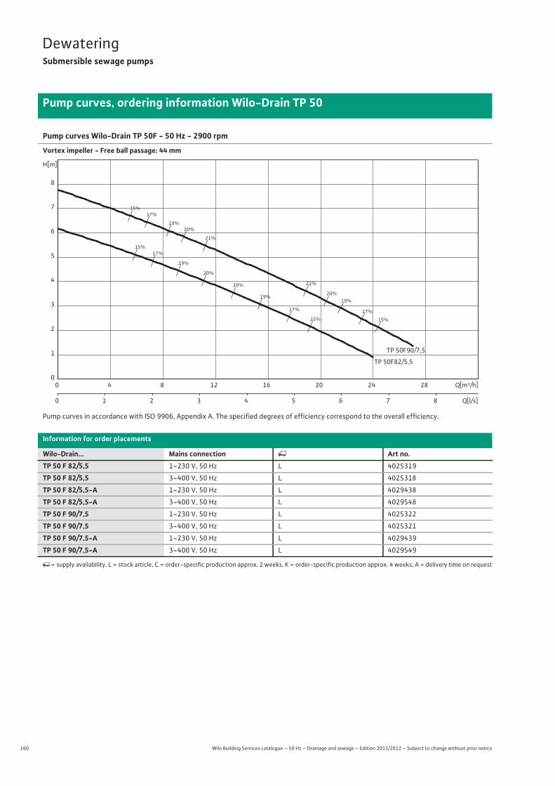
160 Wilo Building Services catalogue – 50 Hz – Drainage and sewage – Edition 2011/2012 – Subject to change without prior notice
DewateringSubmersible sewage pumps
Pump curves, ordering information Wilo-Drain TP 50
Pump curves Wilo-Drain TP 50F - 50 Hz - 2900 rpm
Vortex impeller - Free ball passage: 44 mm
Pump curves in accordance with ISO 9906, Appendix A. The specified degrees of efficiency correspond to the overall efficiency.
Information for order placements
Wilo-Drain... Mains connection � Art no.TP 50 F 82/5,5 1~230 V, 50 Hz L 4025319
TP 50 F 82/5,5 3~400 V, 50 Hz L 4025318
TP 50 F 82/5,5-A 1~230 V, 50 Hz L 4029438
TP 50 F 82/5,5-A 3~400 V, 50 Hz L 4029548
TP 50 F 90/7,5 1~230 V, 50 Hz L 4025322
TP 50 F 90/7,5 3~400 V, 50 Hz L 4025321
TP 50 F 90/7,5-A 1~230 V, 50 Hz L 4029439
TP 50 F 90/7,5-A 3~400 V, 50 Hz L 4029549
�= supply availability, L = stock article, C = order-specific production approx. 2 weeks, K = order-specific production approx. 4 weeks, A = delivery time on request
15%
15%
15%
15%
17%
17%
17%
17%
19%
19%
19%
19%
20%
20%
20%
20%
21%
21%
TP 50F90/7,5
TP 50F82/5,5
Q[m³/h]0 4 8 12 16 20 24 28
Q[l/s]0 1 2 3 4 5 6 7 8
H[m]
0
1
2
3
4
5
6
7
8

161
DewateringSubmersible sewage pumps
Wilo Building Services catalogue – 50 Hz – Drainage and sewage – Edition 2011/2012 – Subject to change without prior notice
Technical data Wilo-Drain TP 50
Dew
ater
ing
TP 50 F 82/5,5 TP 50 F 82/5,5 TP 50 F 82/5,5-A TP 50 F 82/5,5-A1~230 V, 50 Hz 3~400 V, 50 Hz 1~230 V, 50 Hz 3~400 V, 50 Hz
Unit
Pressure connection DN 50 DN 50 DN 50 DN 50
Free ball passage mm 44 44 44 44
Max. volume flow Qmax / m3/h 24 24 24 24
Max. delivery head Hmax / m 6.5 6.5 6.5 6.5
Operating mode (immersed) S1S3-25%
S1S3-25%
S1S3-25%
S1S3-25%
Operating mode (non-immersed) S2-8 min.S3-25%
S2-8 min.S3-25%
S2-8 min.S3-25%
S2-8 min.S3-25%
Max. immersion depth m 10 10 10 10
Protection class IP 68 IP 68 IP 68 IP 68
Fluid temperature T / °C +3 ... +35 +3 ... +35 +3 ... +35 +3 ... +35
Weight approx. m / kg 14.5 14.5 14.5 14.5
Motor data
Nominal current IN / A 4 2 4 2
Starting current IA / A – – – –
Nominal motor power P2 / kW 0.55 0.55 0.55 0.55
Power consumption P1 / kW 1 1 1 1
Activation type Direct Direct Direct Direct
Nominal speed n / rpm 2850 2850 2850 2850
Insulation class F F F F
Recommended switching frequency 1/h 20 20 20 20
Max. switching frequency 1/h 70 70 70 70
Permitted voltage tolerance % +/- 10 +/- 10 +/- 10 +/- 10
Cable
Length of connecting cable m 10 10 10 10
Cable type OZOFLEX (PLUS) 07RNF
OZOFLEX (PLUS) 07RNF
OZOFLEX (PLUS) 07RNF
OZOFLEX (PLUS) 07RNF
Cable cross-section mm2 4G1 6G1 4G1 6G1
Type of connecting cable Detachable Detachable Detachable Detachable
Mains plug – – Shock-proof CEE
Equipment/function
Float switch – – • •Motor protection WSK WSK WSK WSK
Explosion protection – – – –
Materials
Static seal NBR NBR NBR NBR
Impeller PP-GF30 PP-GF30 PP-GF30 PP-GF30
Sealing on motor side NBR NBR NBR NBR
Mechanical seal SiC/SiC SiC/SiC SiC/SiC SiC/SiC
Motor housing 1.4301 1.4301 1.4301 1.4301
Pump housing PP-GF30 PP-GF30 PP-GF30 PP-GF30
Pump shaft 1.4404 1.4404 1.4404 1.4404
P1 refers to the maximum power consumption. All of the data apply to 1~230 V or 3~400 V, 50 Hz and a density of 1 kg/dm3.

162 Wilo Building Services catalogue – 50 Hz – Drainage and sewage – Edition 2011/2012 – Subject to change without prior notice
DewateringSubmersible sewage pumps
Technical data Wilo-Drain TP 50
TP 50 F 90/7,5 TP 50 F 90/7,5 TP 50 F 90/7,5-A TP 50 F 90/7,5-A1~230 V, 50 Hz 3~400 V, 50 Hz 1~230 V, 50 Hz 3~400 V, 50 Hz
Unit
Pressure connection DN 50 DN 50 DN 50 DN 50
Free ball passage mm 44 44 44 44
Max. volume flow Qmax / m3/h 27 27 27 27
Max. delivery head Hmax / m 9 9 9 9
Operating mode (immersed) S1S3-25%
S1S3-25%
S1S3-25%
S1S3-25%
Operating mode (non-immersed) S2-8 min.S3-25%
S2-8 min.S3-25%
S2-8 min.S3-25%
S2-8 min.S3-25%
Max. immersion depth m 10 10 10 10
Protection class IP 68 IP 68 IP 68 IP 68
Fluid temperature T / °C +3 ... +35 +3 ... +35 +3 ... +35 +3 ... +35
Weight approx. m / kg 16 16 16 16
Motor data
Nominal current IN / A 5.5 2.1 5.5 2
Starting current IA / A – – – –
Nominal motor power P2 / kW 0.75 0.75 0.75 0.75
Power consumption P1 / kW 1.3 1.1 1.3 1.1
Activation type Direct Direct Direct Direct
Nominal speed n / rpm 2850 2850 2850 2850
Insulation class F F F F
Recommended switching frequency 1/h 20 20 20 20
Max. switching frequency 1/h 70 70 70 70
Permitted voltage tolerance % +/- 10 +/- 10 +/- 10 +/- 10
Cable
Length of connecting cable m 10 10 10 10
Cable type OZOFLEX (PLUS) 07RNF
OZOFLEX (PLUS) 07RNF
OZOFLEX (PLUS) 07RNF
OZOFLEX (PLUS) 07RNF
Cable cross-section mm2 4G1 6G1 4G1 6G1
Type of connecting cable Detachable Detachable Detachable Detachable
Mains plug – – Shock-proof CEE
Equipment/function
Float switch – – • •Motor protection WSK WSK WSK WSK
Explosion protection – – – –
Materials
Static seal NBR NBR NBR NBR
Impeller PP-GF30 PP-GF30 PP-GF30 PP-GF30
Sealing on motor side NBR NBR NBR NBR
Mechanical seal SiC/SiC SiC/SiC SiC/SiC SiC/SiC
Motor housing 1.4301 1.4301 1.4301 1.4301
Pump housing PP-GF30 PP-GF30 PP-GF30 PP-GF30
Pump shaft 1.4404 1.4404 1.4404 1.4404
P1 refers to the maximum power consumption. All of the data apply to 1~230 V or 3~400 V, 50 Hz and a density of 1 kg/dm3.
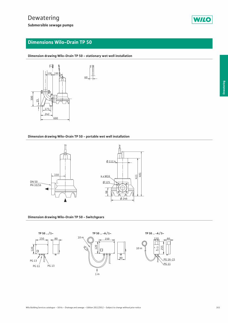
163
DewateringSubmersible sewage pumps
Dew
ater
ing
Dimensions Wilo-Drain TP 50
Wilo Building Services catalogue – 50 Hz – Drainage and sewage – Edition 2011/2012 – Subject to change without prior notice
Dimension drawing Wilo-Drain TP 50 - stationary wet well installation
Dimension drawing Wilo-Drain TP 50 - portable wet well installation
Dimension drawing Wilo-Drain TP 50 - Switchgears
60190130
300
15
173
242600
Ø 125
Ø 246
481
411
Ø 112,4
98
150 4 x M16
DN 50PN 10/16
PG 11
PG 16-21
255
110
10 m
80
TP 50 ... -A / 3~
PG 11 PG 13
PG 13
120
150 80
120
80
15010 m
1 m
TP 50 ... / 1~ TP 50 ... -A / 1~
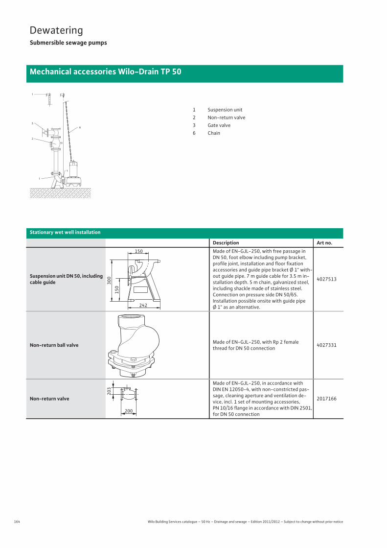
164 Wilo Building Services catalogue – 50 Hz – Drainage and sewage – Edition 2011/2012 – Subject to change without prior notice
DewateringSubmersible sewage pumps
Mechanical accessories Wilo-Drain TP 50
1
3
2
1
1
6
1 Suspension unit2 Non-return valve3 Gate valve6 Chain
Stationary wet well installation
Description Art no.
Suspension unit DN 50, including cable guide
Made of EN-GJL-250, with free passage in DN 50, foot elbow including pump bracket, profile joint, installation and floor fixationaccessories and guide pipe bracket Ø 1" with-out guide pipe. 7 m guide cable for 3.5 m in-stallation depth. 5 m chain, galvanized steel, including shackle made of stainless steel. Connection on pressure side DN 50/65.Installation possible onsite with guide pipe Ø 1" as an alternative.
4027513
Non-return ball valve Made of EN-GJL-250, with Rp 2 female thread for DN 50 connection 4027331
Non-return valve
Made of EN-GJL-250, in accordance with DIN EN 12050-4, with non-constricted pas-sage, cleaning aperture and ventilation de-vice, incl. 1 set of mounting accessories, PN 10/16 flange in accordance with DIN 2501, for DN 50 connection
2017166
150
150
300
242
203
200
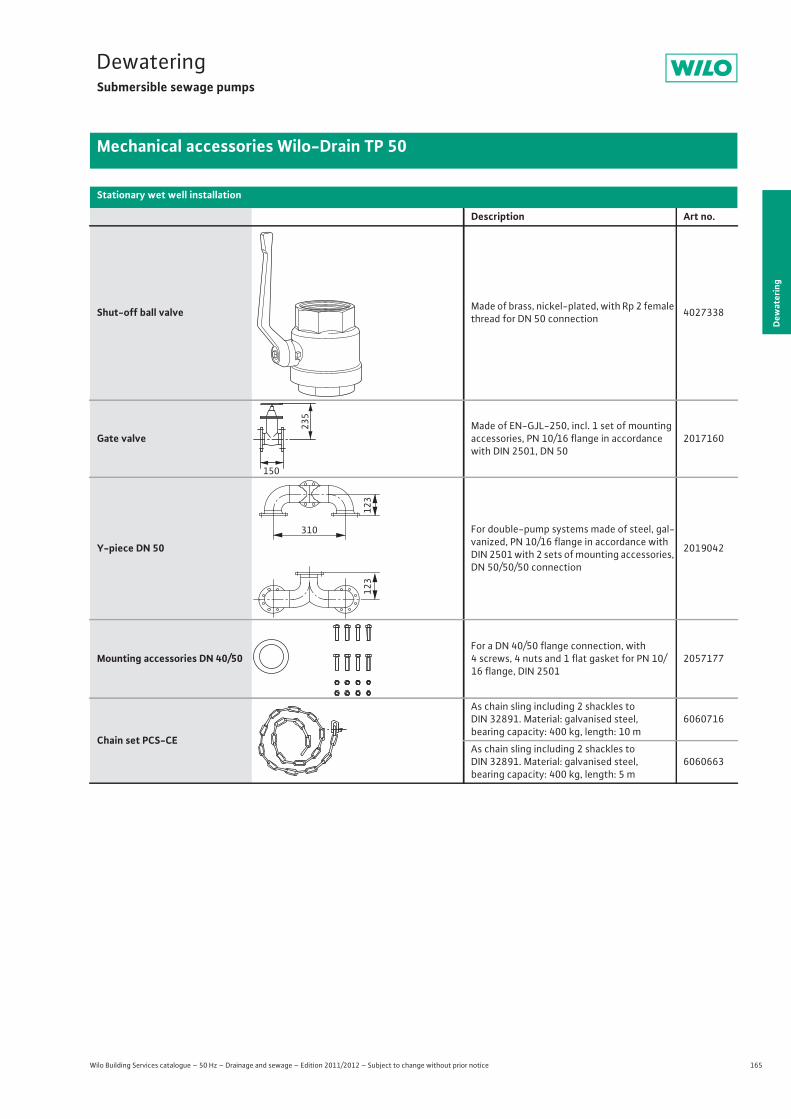
165
DewateringSubmersible sewage pumps
Dew
ater
ing
Mechanical accessories Wilo-Drain TP 50
Wilo Building Services catalogue – 50 Hz – Drainage and sewage – Edition 2011/2012 – Subject to change without prior notice
Shut-off ball valve Made of brass, nickel-plated, with Rp 2 female thread for DN 50 connection 4027338
Gate valveMade of EN-GJL-250, incl. 1 set of mounting accessories, PN 10/16 flange in accordance with DIN 2501, DN 50
2017160
Y-piece DN 50
For double-pump systems made of steel, gal-vanized, PN 10/16 flange in accordance with DIN 2501 with 2 sets of mounting accessories, DN 50/50/50 connection
2019042
Mounting accessories DN 40/50For a DN 40/50 flange connection, with 4 screws, 4 nuts and 1 flat gasket for PN 10/16 flange, DIN 2501
2057177
Chain set PCS-CE
As chain sling including 2 shackles to DIN 32891. Material: galvanised steel, bearing capacity: 400 kg, length: 10 m
6060716
As chain sling including 2 shackles to DIN 32891. Material: galvanised steel, bearing capacity: 400 kg, length: 5 m
6060663
Stationary wet well installation
Description Art no.
150
235
123
123
310
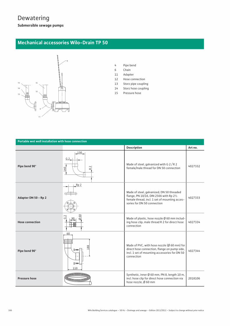
166 Wilo Building Services catalogue – 50 Hz – Drainage and sewage – Edition 2011/2012 – Subject to change without prior notice
DewateringSubmersible sewage pumps
Mechanical accessories Wilo-Drain TP 50
Portable wet well installation with hose connection
Description Art no.
Pipe bend 90° Made of steel, galvanized with G 2 / R 2female/male thread for DN 50 connection 4027332
Adapter DN 50 - Rp 2
Made of steel, galvanized, DN 50 threaded flange, PN 10/16, DIN 2566 with Rp 2½female thread, incl. 1 set of mounting acces-sories for DN 50 connection
4027333
Hose connectionMade of plastic, hose nozzle Ø 60 mm includ-ing hose clip, male thread R 2 for direct hose connection
4027334
Pipe bend 90°
Made of PVC, with hose nozzle (Ø 60 mm) for direct hose connection, flange on pump side, incl. 1 set of mounting accessories for DN 50 connection
4027344
Pressure hoseSynthetic, inner Ø 60 mm, PN 8, length 10 m, incl. hose clip for direct hose connection via hose nozzle, Ø 60 mm
2018106
13
14
6
15
11
15
12
4
4 Pipe bend6 Chain11 Adapter12 Hose connection13 Storz pipe coupling14 Storz hose coupling15 Pressure hose
130
G 2
R 2
140
Rp 2
90 Ø 60
G 2
60
110
188
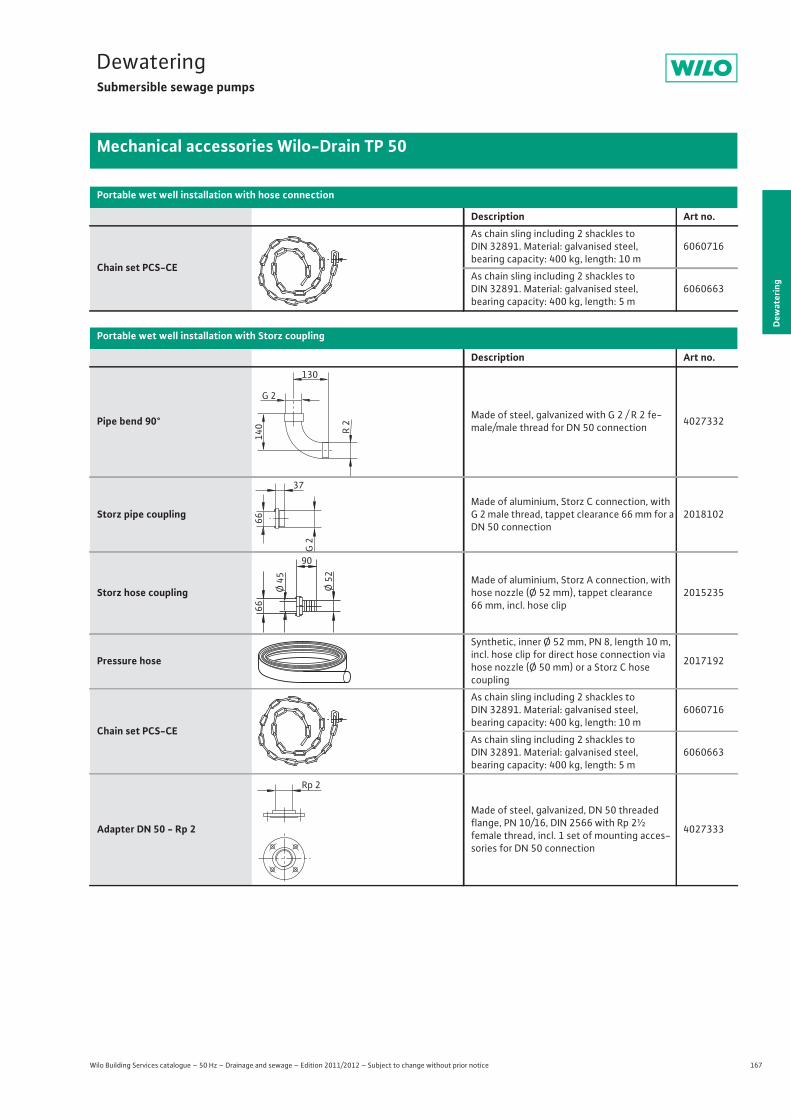
167
DewateringSubmersible sewage pumps
Dew
ater
ing
Mechanical accessories Wilo-Drain TP 50
Wilo Building Services catalogue – 50 Hz – Drainage and sewage – Edition 2011/2012 – Subject to change without prior notice
Chain set PCS-CE
As chain sling including 2 shackles to DIN 32891. Material: galvanised steel, bearing capacity: 400 kg, length: 10 m
6060716
As chain sling including 2 shackles to DIN 32891. Material: galvanised steel, bearing capacity: 400 kg, length: 5 m
6060663
Portable wet well installation with Storz coupling
Description Art no.
Pipe bend 90° Made of steel, galvanized with G 2 / R 2 fe-male/male thread for DN 50 connection 4027332
Storz pipe couplingMade of aluminium, Storz C connection, with G 2 male thread, tappet clearance 66 mm for a DN 50 connection
2018102
Storz hose couplingMade of aluminium, Storz A connection, with hose nozzle (Ø 52 mm), tappet clearance 66 mm, incl. hose clip
2015235
Pressure hose
Synthetic, inner Ø 52 mm, PN 8, length 10 m, incl. hose clip for direct hose connection via hose nozzle (Ø 50 mm) or a Storz C hosecoupling
2017192
Chain set PCS-CE
As chain sling including 2 shackles to DIN 32891. Material: galvanised steel, bearing capacity: 400 kg, length: 10 m
6060716
As chain sling including 2 shackles to DIN 32891. Material: galvanised steel, bearing capacity: 400 kg, length: 5 m
6060663
Adapter DN 50 - Rp 2
Made of steel, galvanized, DN 50 threaded flange, PN 10/16, DIN 2566 with Rp 2½female thread, incl. 1 set of mounting acces-sories for DN 50 connection
4027333
Portable wet well installation with hose connection
Description Art no.
130
G 2
R 2
140
G 2
37
66
90
Ø 52
66
Ø 45
Rp 2
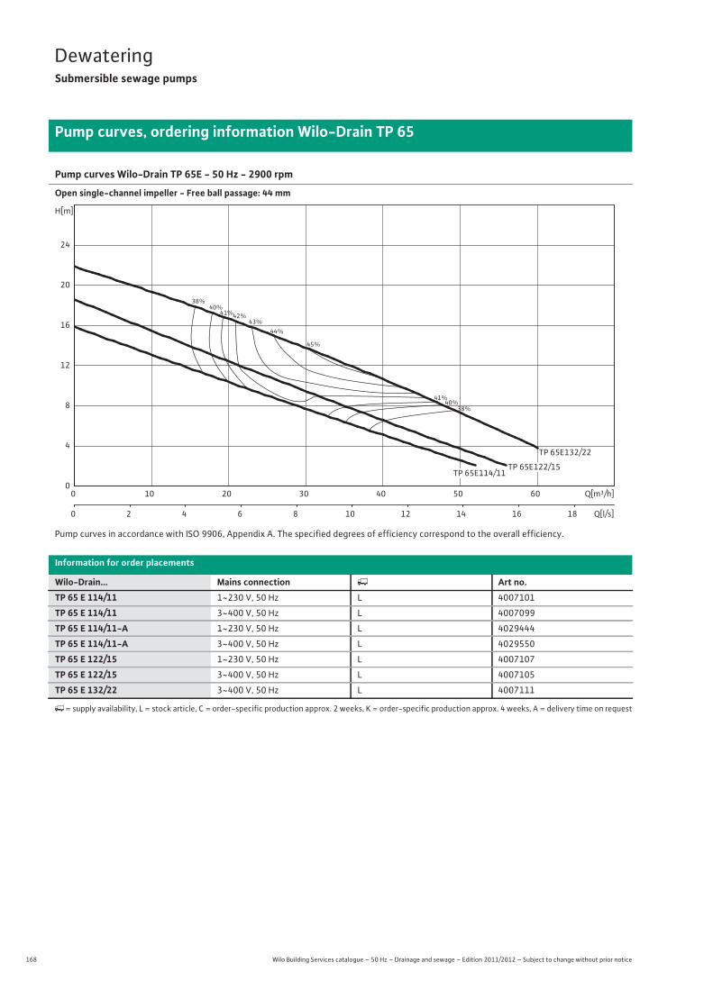
168 Wilo Building Services catalogue – 50 Hz – Drainage and sewage – Edition 2011/2012 – Subject to change without prior notice
DewateringSubmersible sewage pumps
Pump curves, ordering information Wilo-Drain TP 65
Pump curves Wilo-Drain TP 65E - 50 Hz - 2900 rpm
Open single-channel impeller - Free ball passage: 44 mm
Pump curves in accordance with ISO 9906, Appendix A. The specified degrees of efficiency correspond to the overall efficiency.
Information for order placements
Wilo-Drain... Mains connection � Art no.TP 65 E 114/11 1~230 V, 50 Hz L 4007101
TP 65 E 114/11 3~400 V, 50 Hz L 4007099
TP 65 E 114/11-A 1~230 V, 50 Hz L 4029444
TP 65 E 114/11-A 3~400 V, 50 Hz L 4029550
TP 65 E 122/15 1~230 V, 50 Hz L 4007107
TP 65 E 122/15 3~400 V, 50 Hz L 4007105
TP 65 E 132/22 3~400 V, 50 Hz L 4007111
�= supply availability, L = stock article, C = order-specific production approx. 2 weeks, K = order-specific production approx. 4 weeks, A = delivery time on request
38%
38%
40%
40%
41%
41%
42%43%
44%
45%
TP 65E132/22
Q[m³/h]0 10 20 30 40 50 60
Q[l/s]0 2 4 6 8 10 12 14 16 18
H[m]
0
4
8
12
16
20
24
TP 65E114/11TP 65E122/15
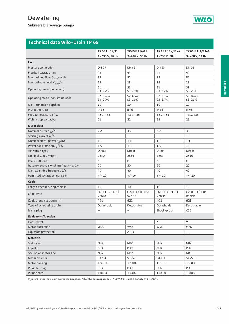
169
DewateringSubmersible sewage pumps
Wilo Building Services catalogue – 50 Hz – Drainage and sewage – Edition 2011/2012 – Subject to change without prior notice
Technical data Wilo-Drain TP 65
Dew
ater
ing
TP 65 E 114/11 TP 65 E 114/11 TP 65 E 114/11-A TP 65 E 114/11-A1~230 V, 50 Hz 3~400 V, 50 Hz 1~230 V, 50 Hz 3~400 V, 50 Hz
Unit
Pressure connection DN 65 DN 65 DN 65 DN 65
Free ball passage mm 44 44 44 44
Max. volume flow Qmax / m3/h 52 52 52 52
Max. delivery head Hmax / m 15 15 15 15
Operating mode (immersed) S1S3-25%
S1S3-25%
S1S3-25%
S1S3-25%
Operating mode (non-immersed) S2-8 min.S3-25%
S2-8 min.S3-25%
S2-8 min.S3-25%
S2-8 min.S3-25%
Max. immersion depth m 10 10 10 10
Protection class IP 68 IP 68 IP 68 IP 68
Fluid temperature T / °C +3 ... +35 +3 ... +35 +3 ... +35 +3 ... +35
Weight approx. m / kg 21 21 21 21
Motor data
Nominal current IN / A 7.2 3.2 7.2 3.2
Starting current IA / A – – – –
Nominal motor power P2 / kW 1.1 1.1 1.1 1.1
Power consumption P1 / kW 1.5 1.5 1.5 1.5
Activation type Direct Direct Direct Direct
Nominal speed n / rpm 2850 2850 2850 2850
Insulation class F F F F
Recommended switching frequency 1/h 20 20 20 20
Max. switching frequency 1/h 40 40 40 40
Permitted voltage tolerance % +/- 10 +/- 10 +/- 10 +/- 10
Cable
Length of connecting cable m 10 10 10 10
Cable type OZOFLEX (PLUS) 07RNF
OZOFLEX (PLUS) 07RNF
OZOFLEX (PLUS) 07RNF
OZOFLEX (PLUS) 07RNF
Cable cross-section mm2 4G1 6G1 4G1 6G1
Type of connecting cable Detachable Detachable Detachable Detachable
Mains plug – – Shock-proof CEE
Equipment/function
Float switch – – • •Motor protection WSK WSK WSK WSK
Explosion protection – ATEX – –
Materials
Static seal NBR NBR NBR NBR
Impeller PUR PUR PUR PUR
Sealing on motor side NBR NBR NBR NBR
Mechanical seal SiC/SiC SiC/SiC SiC/SiC SiC/SiC
Motor housing 1.4301 1.4301 1.4301 1.4301
Pump housing PUR PUR PUR PUR
Pump shaft 1.4404 1.4404 1.4404 1.4404
P1 refers to the maximum power consumption. All of the data applies to 3~400 V, 50 Hz and a density of 1 kg/dm3.

170 Wilo Building Services catalogue – 50 Hz – Drainage and sewage – Edition 2011/2012 – Subject to change without prior notice
DewateringSubmersible sewage pumps
Technical data Wilo-Drain TP 65
TP 65 E 122/15 TP 65 E 122/15 TP 65 E 132/221~230 V, 50 Hz 3~400 V, 50 Hz 3~400 V, 50 Hz
Unit
Pressure connection DN 65 DN 65 DN 65
Free ball passage mm 44 44 44
Max. volume flow Qmax / m3/h 56 56 60
Max. delivery head Hmax / m 18 18 21
Operating mode (immersed) S1S3-25%
S1S3-25%
S1S3-25%
Operating mode (non-immersed) S2-8 min.S3-25%
S2-8 min.S3-25%
S2-8 min.S3-25%
Max. immersion depth m 10 10 10
Protection class IP 68 IP 68 IP 68
Fluid temperature T / °C +3 ... +35 +3 ... +35 +3 ... +35
Weight approx. m / kg 22 22 24.5
Motor data
Nominal current IN / A 9.5 3.8 5.2
Starting current IA / A – – –
Nominal motor power P2 / kW 1.5 1.5 2.2
Power consumption P1 / kW 2 2 2.9
Activation type Direct Direct Direct
Nominal speed n / rpm 2850 2850 2850
Insulation class F F F
Recommended switching frequency 1/h 20 20 20
Max. switching frequency 1/h 40 40 40
Permitted voltage tolerance % +/- 10 +/- 10 +/- 10
Cable
Length of connecting cable m 10 10 10
Cable type OZOFLEX (PLUS) 07RNF OZOFLEX (PLUS) 07RNF OZOFLEX (PLUS) 07RNF
Cable cross-section mm2 4G1 6G1 6G1,5
Type of connecting cable Detachable Detachable Detachable
Mains plug – – –
Equipment/function
Float switch – – –
Motor protection WSK WSK WSK
Explosion protection – ATEX ATEX
Materials
Static seal NBR NBR NBR
Impeller PUR PUR PUR
Sealing on motor side NBR NBR NBR
Mechanical seal SiC/SiC SiC/SiC SiC/SiC
Motor housing 1.4301 1.4301 1.4301
Pump housing PUR PUR PUR
Pump shaft 1.4404 1.4404 1.4404
P1 refers to the maximum power consumption. All of the data applies to 3~400 V, 50 Hz and a density of 1 kg/dm3.
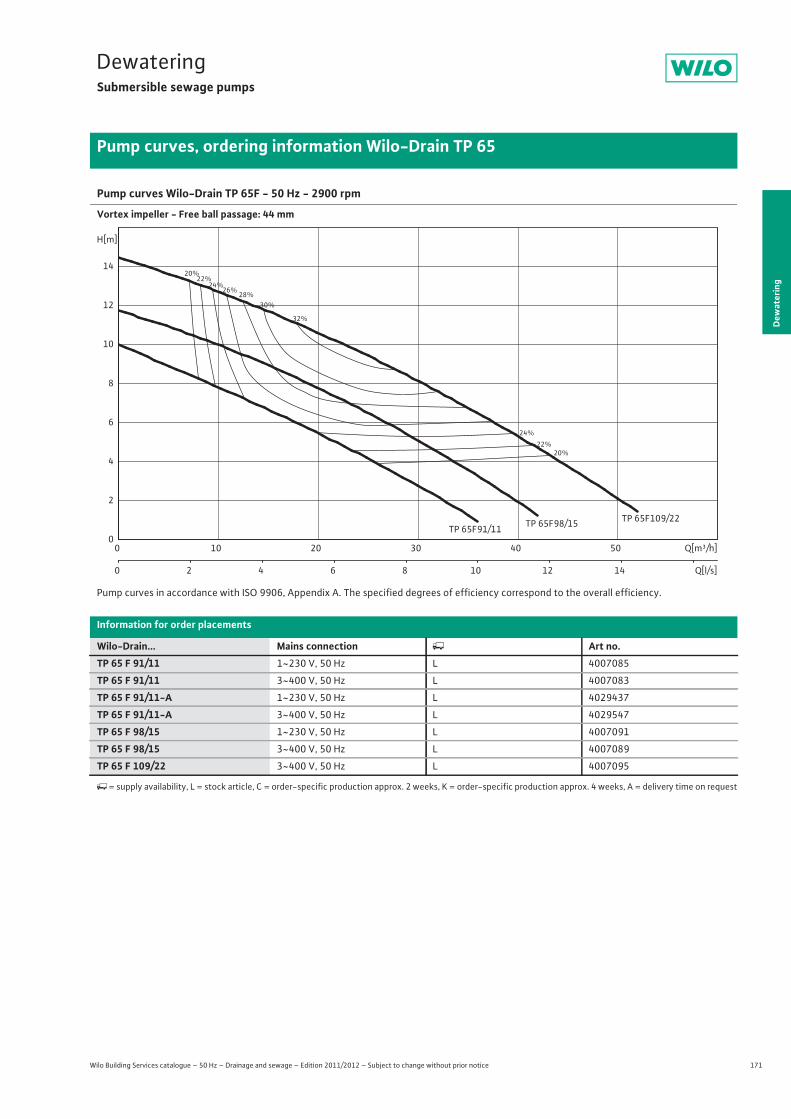
171
DewateringSubmersible sewage pumps
Dew
ater
ing
Pump curves, ordering information Wilo-Drain TP 65
Wilo Building Services catalogue – 50 Hz – Drainage and sewage – Edition 2011/2012 – Subject to change without prior notice
Pump curves Wilo-Drain TP 65F - 50 Hz - 2900 rpm
Vortex impeller - Free ball passage: 44 mm
Pump curves in accordance with ISO 9906, Appendix A. The specified degrees of efficiency correspond to the overall efficiency.
Information for order placements
Wilo-Drain... Mains connection � Art no.TP 65 F 91/11 1~230 V, 50 Hz L 4007085
TP 65 F 91/11 3~400 V, 50 Hz L 4007083
TP 65 F 91/11-A 1~230 V, 50 Hz L 4029437
TP 65 F 91/11-A 3~400 V, 50 Hz L 4029547
TP 65 F 98/15 1~230 V, 50 Hz L 4007091
TP 65 F 98/15 3~400 V, 50 Hz L 4007089
TP 65 F 109/22 3~400 V, 50 Hz L 4007095
�= supply availability, L = stock article, C = order-specific production approx. 2 weeks, K = order-specific production approx. 4 weeks, A = delivery time on request
20%
20%
22%
22%
24%
24%
26%28%
30%
32%
TP 65F109/22TP 65F91/11 TP 65F98/15
Q[m³/h]0 10 20 30 40 50
Q[l/s]0 2 4 6 8 10 12 14
H[m]
0
2
4
6
8
10
12
14
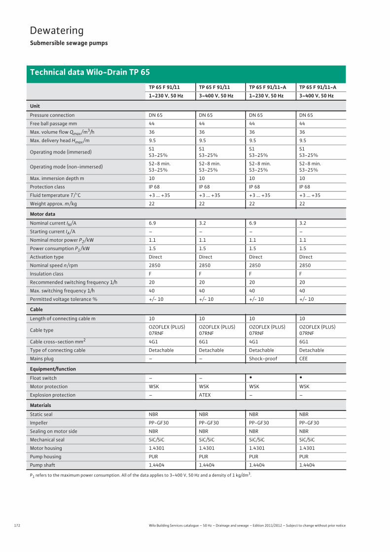
172 Wilo Building Services catalogue – 50 Hz – Drainage and sewage – Edition 2011/2012 – Subject to change without prior notice
DewateringSubmersible sewage pumps
Technical data Wilo-Drain TP 65
TP 65 F 91/11 TP 65 F 91/11 TP 65 F 91/11-A TP 65 F 91/11-A1~230 V, 50 Hz 3~400 V, 50 Hz 1~230 V, 50 Hz 3~400 V, 50 Hz
Unit
Pressure connection DN 65 DN 65 DN 65 DN 65
Free ball passage mm 44 44 44 44
Max. volume flow Qmax / m3/h 36 36 36 36
Max. delivery head Hmax / m 9.5 9.5 9.5 9.5
Operating mode (immersed) S1S3-25%
S1S3-25%
S1S3-25%
S1S3-25%
Operating mode (non-immersed) S2-8 min.S3-25%
S2-8 min.S3-25%
S2-8 min.S3-25%
S2-8 min.S3-25%
Max. immersion depth m 10 10 10 10
Protection class IP 68 IP 68 IP 68 IP 68
Fluid temperature T / °C +3 ... +35 +3 ... +35 +3 ... +35 +3 ... +35
Weight approx. m / kg 22 22 22 22
Motor data
Nominal current IN / A 6.9 3.2 6.9 3.2
Starting current IA / A – – – –
Nominal motor power P2 / kW 1.1 1.1 1.1 1.1
Power consumption P1 / kW 1.5 1.5 1.5 1.5
Activation type Direct Direct Direct Direct
Nominal speed n / rpm 2850 2850 2850 2850
Insulation class F F F F
Recommended switching frequency 1/h 20 20 20 20
Max. switching frequency 1/h 40 40 40 40
Permitted voltage tolerance % +/- 10 +/- 10 +/- 10 +/- 10
Cable
Length of connecting cable m 10 10 10 10
Cable type OZOFLEX (PLUS) 07RNF
OZOFLEX (PLUS) 07RNF
OZOFLEX (PLUS) 07RNF
OZOFLEX (PLUS) 07RNF
Cable cross-section mm2 4G1 6G1 4G1 6G1
Type of connecting cable Detachable Detachable Detachable Detachable
Mains plug – – Shock-proof CEE
Equipment/function
Float switch – – • •Motor protection WSK WSK WSK WSK
Explosion protection – ATEX – –
Materials
Static seal NBR NBR NBR NBR
Impeller PP-GF30 PP-GF30 PP-GF30 PP-GF30
Sealing on motor side NBR NBR NBR NBR
Mechanical seal SiC/SiC SiC/SiC SiC/SiC SiC/SiC
Motor housing 1.4301 1.4301 1.4301 1.4301
Pump housing PUR PUR PUR PUR
Pump shaft 1.4404 1.4404 1.4404 1.4404
P1 refers to the maximum power consumption. All of the data applies to 3~400 V, 50 Hz and a density of 1 kg/dm3.

173
DewateringSubmersible sewage pumps
Wilo Building Services catalogue – 50 Hz – Drainage and sewage – Edition 2011/2012 – Subject to change without prior notice
Technical data Wilo-Drain TP 65
Dew
ater
ing
TP 65 F 98/15 TP 65 F 98/15 TP 65 F 109/221~230 V, 50 Hz 3~400 V, 50 Hz 3~400 V, 50 Hz
Unit
Pressure connection DN 65 DN 65 DN 65
Free ball passage mm 44 44 44
Max. volume flow Qmax / m3/h 42 42 52
Max. delivery head Hmax / m 11.5 11.5 14.5
Operating mode (immersed) S1S3-25%
S1S3-25%
S1S3-25%
Operating mode (non-immersed) S2-8 min.S3-25%
S2-8 min.S3-25%
S2-8 min.S3-25%
Max. immersion depth m 10 10 10
Protection class IP 68 IP 68 IP 68
Fluid temperature T / °C +3 ... +35 +3 ... +35 +3 ... +35
Weight approx. m / kg 24.5 24.5 24.5
Motor data
Nominal current IN / A 9.5 3.6 5.1
Starting current IA / A – – –
Nominal motor power P2 / kW 1.5 1.5 2.2
Power consumption P1 / kW 1.8 1.8 2.7
Activation type Direct Direct Direct
Nominal speed n / rpm 2850 2850 2850
Insulation class F F F
Recommended switching frequency 1/h 20 20 20
Max. switching frequency 1/h 40 40 40
Permitted voltage tolerance % +/- 10 +/- 10 +/- 10
Cable
Length of connecting cable m 10 10 10
Cable type OZOFLEX (PLUS) 07RNF OZOFLEX (PLUS) 07RNF OZOFLEX (PLUS) 07RNF
Cable cross-section mm2 6G1 6G1 6G1,5
Type of connecting cable Detachable Detachable Detachable
Mains plug – – –
Equipment/function
Float switch – – –
Motor protection WSK WSK WSK
Explosion protection – ATEX ATEX
Materials
Static seal NBR NBR NBR
Impeller PP-GF30 PP-GF30 PP-GF30
Sealing on motor side NBR NBR NBR
Mechanical seal SiC/SiC SiC/SiC SiC/SiC
Motor housing 1.4301 1.4301 1.4301
Pump housing PUR PUR PUR
Pump shaft 1.4404 1.4404 1.4404
P1 refers to the maximum power consumption. All of the data applies to 3~400 V, 50 Hz and a density of 1 kg/dm3.
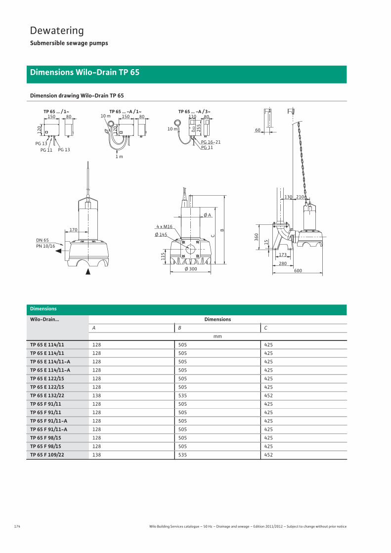
174 Wilo Building Services catalogue – 50 Hz – Drainage and sewage – Edition 2011/2012 – Subject to change without prior notice
DewateringSubmersible sewage pumps
Dimensions Wilo-Drain TP 65
Dimension drawing Wilo-Drain TP 65
Dimensions
Wilo-Drain... DimensionsA B C
mm
TP 65 E 114/11 128 505 425
TP 65 E 114/11 128 505 425
TP 65 E 114/11-A 128 505 425
TP 65 E 114/11-A 128 505 425
TP 65 E 122/15 128 505 425
TP 65 E 122/15 128 505 425
TP 65 E 132/22 138 535 452
TP 65 F 91/11 128 505 425
TP 65 F 91/11 128 505 425
TP 65 F 91/11-A 128 505 425
TP 65 F 91/11-A 128 505 425
TP 65 F 98/15 128 505 425
TP 65 F 98/15 128 505 425
TP 65 F 109/22 138 535 452
60
210130
360
15
173
280600
Ø 145 C Ø A
115
B 170
Ø 300
4 x M16
PG 11 PG 16-21
255
110
10 m
80
DN 65PN 10/16
TP 65 ... -A / 3~12
0150
PG 11 PG 13 PG 13
120
150 80 8010 m
1 m
TP 65 ... -A / 1~TP 65 ... / 1~
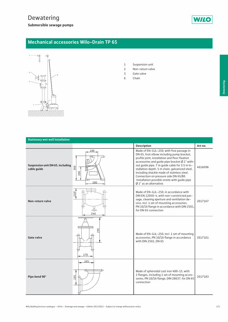
175
DewateringSubmersible sewage pumps
Dew
ater
ing
Mechanical accessories Wilo-Drain TP 65
Wilo Building Services catalogue – 50 Hz – Drainage and sewage – Edition 2011/2012 – Subject to change without prior notice
Stationary wet well installation
Description Art no.
Suspension unit DN 65, including cable guide
Made of EN-GJL-250, with free passage in DN 65, foot elbow including pump bracket, profile joint, installation and floor fixationaccessories and guide pipe bracket Ø 1" with-out guide pipe. 7 m guide cable for 3.5 m in-stallation depth. 5 m chain, galvanized steel, including shackle made of stainless steel. Connection on pressure side DN 65/80. Installation possible onsite with guide pipe Ø 1" as an alternative.
4016096
Non-return valve
Made of EN-GJL-250, in accordance with DIN EN 12050-4, with non-constricted pas-sage, cleaning aperture and ventilation de-vice, incl. 1 set of mounting accessories, PN 10/16 flange in accordance with DIN 2501, for DN 65 connection
2017167
Gate valveMade of EN-GJL-250, incl. 1 set of mounting accessories, PN 10/16 flange in accordance with DIN 2501, DN 65
2017161
Pipe bend 90°
Made of spheroidal cast iron 400-15, with 2 flanges, including 1 set of mounting acces-sories, PN 10/16 flange, DIN 28637, for DN 65 connection
2017183
1
3
2
1
1
6
1 Suspension unit2 Non-return valve3 Gate valve6 Chain
180
200
360
280
218*
240
295
170
165
165
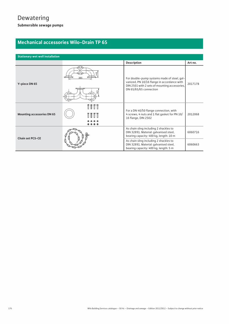
176 Wilo Building Services catalogue – 50 Hz – Drainage and sewage – Edition 2011/2012 – Subject to change without prior notice
DewateringSubmersible sewage pumps
Mechanical accessories Wilo-Drain TP 65
Y-piece DN 65
For double-pump systems made of steel, gal-vanized, PN 10/16 flange in accordance with DIN 2501 with 2 sets of mounting accessories, DN 65/65/65 connection
2017178
Mounting accessories DN 65For a DN 40/50 flange connection, with 4 screws, 4 nuts and 1 flat gasket for PN 10/16 flange, DIN 2502
2012068
Chain set PCS-CE
As chain sling including 2 shackles to DIN 32891. Material: galvanised steel, bearing capacity: 400 kg, length: 10 m
6060716
As chain sling including 2 shackles to DIN 32891. Material: galvanised steel, bearing capacity: 400 kg, length: 5 m
6060663
Stationary wet well installation
Description Art no.
143
385
143
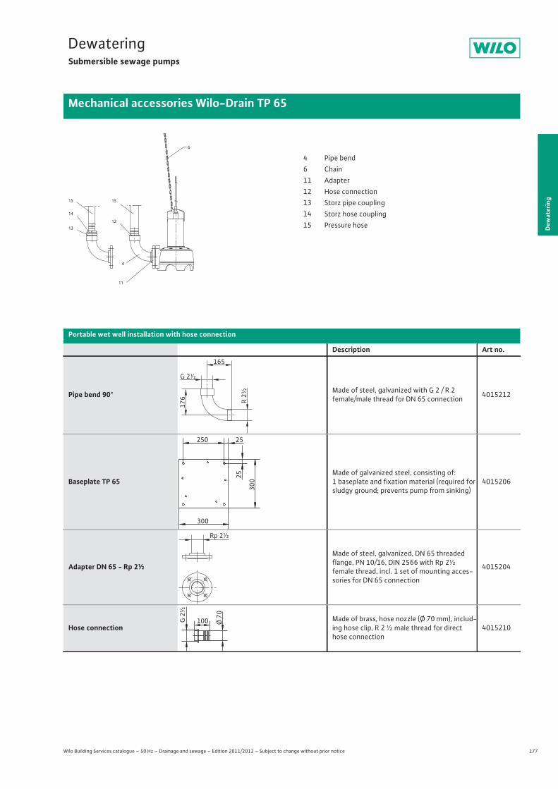
177
DewateringSubmersible sewage pumps
Dew
ater
ing
Mechanical accessories Wilo-Drain TP 65
Wilo Building Services catalogue – 50 Hz – Drainage and sewage – Edition 2011/2012 – Subject to change without prior notice
13
14
6
15
11
15
12
4
4 Pipe bend6 Chain11 Adapter12 Hose connection13 Storz pipe coupling14 Storz hose coupling15 Pressure hose
Portable wet well installation with hose connection
Description Art no.
Pipe bend 90° Made of steel, galvanized with G 2 / R 2female/male thread for DN 65 connection 4015212
Baseplate TP 65Made of galvanized steel, consisting of: 1 baseplate and fixation material (required for sludgy ground; prevents pump from sinking)
4015206
Adapter DN 65 - Rp 2½
Made of steel, galvanized, DN 65 threaded flange, PN 10/16, DIN 2566 with Rp 2½female thread, incl. 1 set of mounting acces-sories for DN 65 connection
4015204
Hose connectionMade of brass, hose nozzle (Ø 70 mm), includ-ing hose clip, R 2 ½ male thread for direct hose connection
4015210
165
G 2½
R 2½
176
250 25
25
300
300
Rp 2½
100 Ø 70
G 2
½
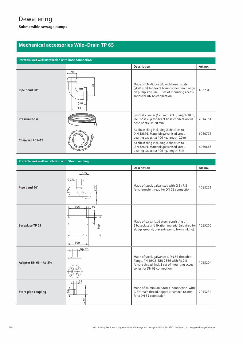
178 Wilo Building Services catalogue – 50 Hz – Drainage and sewage – Edition 2011/2012 – Subject to change without prior notice
DewateringSubmersible sewage pumps
Mechanical accessories Wilo-Drain TP 65
Pipe bend 90°
Made of EN-GJL-250, with hose nozzle (Ø 70 mm) for direct hose connection, flange on pump side, incl. 1 set of mounting acces-sories for DN 65 connection
4027346
Pressure hoseSynthetic, inner Ø 70 mm, PN 8, length 10 m, incl. hose clip for direct hose connection via hose nozzle, Ø 70 mm
2014151
Chain set PCS-CE
As chain sling including 2 shackles to DIN 32891. Material: galvanised steel, bearing capacity: 400 kg, length: 10 m
6060716
As chain sling including 2 shackles to DIN 32891. Material: galvanised steel, bearing capacity: 400 kg, length: 5 m
6060663
Portable wet well installation with Storz coupling
Description Art no.
Pipe bend 90° Made of steel, galvanized with G 2 / R 2female/male thread for DN 65 connection 4015212
Baseplate TP 65Made of galvanized steel, consisting of: 1 baseplate and fixation material (required for sludgy ground; prevents pump from sinking)
4015206
Adapter DN 65 - Rp 2½
Made of steel, galvanized, DN 65 threaded flange, PN 10/16, DIN 2566 with Rp 2½female thread, incl. 1 set of mounting acces-sories for DN 65 connection
4015204
Storz pipe couplingMade of aluminium, Storz C connection, with G 2½ male thread, tappet clearance 66 mm for a DN 65 connection
2015234
Portable wet well installation with hose connection
Description Art no.70
75
170
165
G 2½
R 2½
176
250 25
25
300
300
Rp 2½
G 2
½
37
66
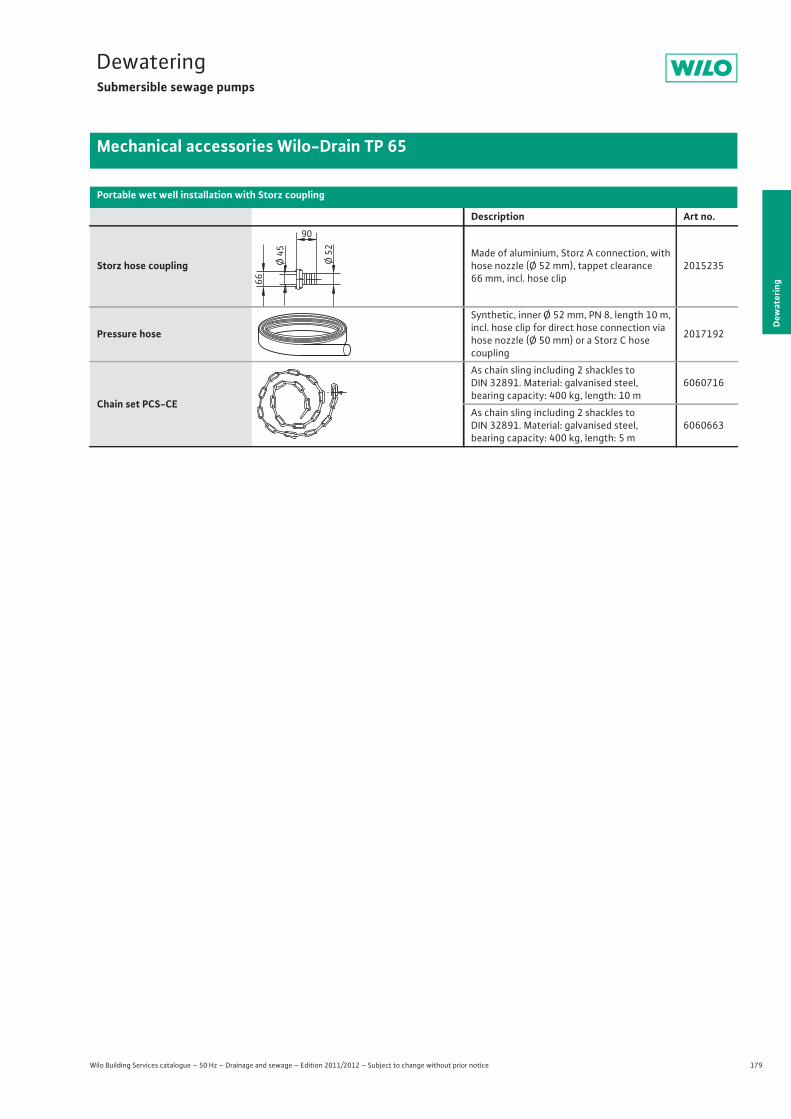
179
DewateringSubmersible sewage pumps
Dew
ater
ing
Mechanical accessories Wilo-Drain TP 65
Wilo Building Services catalogue – 50 Hz – Drainage and sewage – Edition 2011/2012 – Subject to change without prior notice
Storz hose couplingMade of aluminium, Storz A connection, with hose nozzle (Ø 52 mm), tappet clearance 66 mm, incl. hose clip
2015235
Pressure hose
Synthetic, inner Ø 52 mm, PN 8, length 10 m, incl. hose clip for direct hose connection via hose nozzle (Ø 50 mm) or a Storz C hosecoupling
2017192
Chain set PCS-CE
As chain sling including 2 shackles to DIN 32891. Material: galvanised steel, bearing capacity: 400 kg, length: 10 m
6060716
As chain sling including 2 shackles to DIN 32891. Material: galvanised steel, bearing capacity: 400 kg, length: 5 m
6060663
Portable wet well installation with Storz coupling
Description Art no.90
Ø 52
66
Ø 45
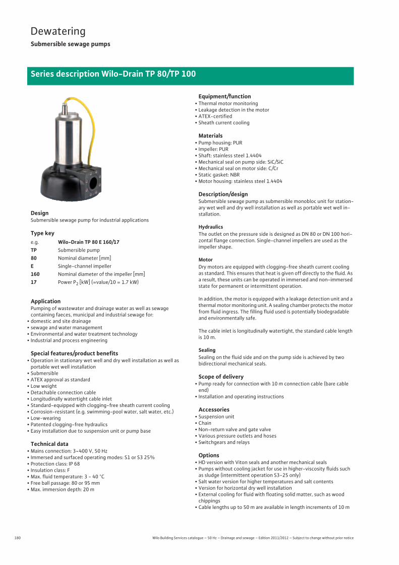
180 Wilo Building Services catalogue – 50 Hz – Drainage and sewage – Edition 2011/2012 – Subject to change without prior notice
DewateringSubmersible sewage pumps
Series description Wilo-Drain TP 80/TP 100
DesignSubmersible sewage pump for industrial applications
Type key
ApplicationPumping of wastewater and drainage water as well as sewagecontaining faeces, municipal and industrial sewage for:
• domestic and site drainage• sewage and water management• Environmental and water treatment technology• Industrial and process engineering
Special features/product benefits• Operation in stationary wet well and dry well installation as well as portable wet well installation
• Submersible• ATEX approval as standard• Low weight• Detachable connection cable• Longitudinally watertight cable inlet• Standard-equipped with clogging-free sheath current cooling• Corrosion-resistant (e.g. swimming-pool water, salt water, etc.)• Low-wearing• Patented clogging-free hydraulics• Easy installation due to suspension unit or pump base
Technical data• Mains connection: 3~400 V, 50 Hz• Immersed and surfaced operating modes: S1 or S3 25%• Protection class: IP 68• Insulation class: F• Max. fluid temperature: 3 - 40 °C• Free ball passage: 80 or 95 mm• Max. immersion depth: 20 m
Equipment/function• Thermal motor monitoring• Leakage detection in the motor• ATEX-certified• Sheath current cooling
Materials• Pump housing: PUR• Impeller: PUR• Shaft: stainless steel 1.4404• Mechanical seal on pump side: SiC/SiC• Mechanical seal on motor side: C/Cr• Static gasket: NBR• Motor housing: stainless steel 1.4404
Description/designSubmersible sewage pump as submersible monobloc unit for station-ary wet well and dry well installation as well as portable wet well in-stallation.
HydraulicsThe outlet on the pressure side is designed as DN 80 or DN 100 hori-zontal flange connection. Single-channel impellers are used as the impeller shape.
MotorDry motors are equipped with clogging-free sheath current cooling as standard. This ensures that heat is given off directly to the fluid. As a result, these units can be operated in immersed and non-immersed state for permanent or intermittent operation.
In addition, the motor is equipped with a leakage detection unit and a thermal motor monitoring unit. A sealing chamber protects the motor from fluid ingress. The filling fluid used is potentially biodegradable and environmentally safe.
The cable inlet is longitudinally watertight, the standard cable length is 10 m.
SealingSealing on the fluid side and on the pump side is achieved by twobidirectional mechanical seals.
Scope of delivery• Pump ready for connection with 10 m connection cable (bare cable end)
• Installation and operating instructions
Accessories• Suspension unit• Chain• Non-return valve and gate valve• Various pressure outlets and hoses• Switchgears and relays
Options• HD version with Viton seals and another mechanical seals• Pumps without cooling jacket for use in higher-viscosity fluids such as sludge (intermittent operation S3-25 only)
• Salt water version for higher temperatures and salt contents• Version for horizontal dry well installation• External cooling for fluid with floating solid matter, such as wood chippings
• Cable lengths up to 50 m are available in length increments of 10 m
e.g. Wilo-Drain TP 80 E 160/17TP Submersible pump80 Nominal diameter [mm]E Single-channel impeller160 Nominal diameter of the impeller [mm]17 Power P2 [kW] (=value/10 = 1.7 kW)
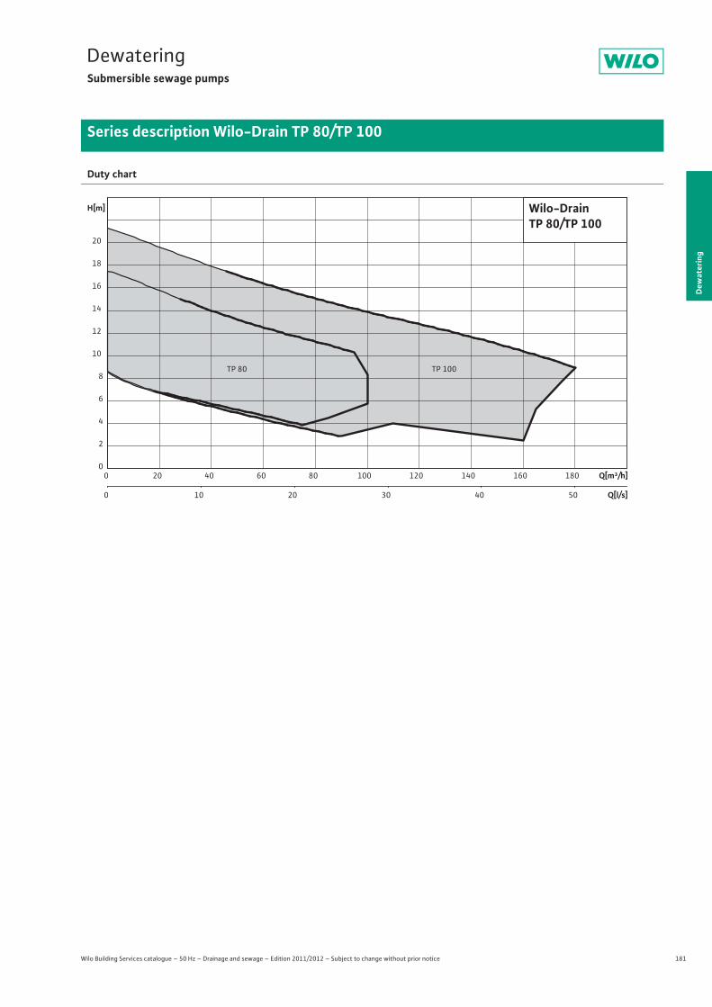
181
DewateringSubmersible sewage pumps
Dew
ater
ing
Series description Wilo-Drain TP 80/TP 100
Wilo Building Services catalogue – 50 Hz – Drainage and sewage – Edition 2011/2012 – Subject to change without prior notice
Duty chart
Q[m³/h]0 20 40 60 80 100 120 140 160 180
Q[l/s]0 10 20 30 40 50
H[m]
0
2
4
6
8
10
12
14
16
18
20
Wilo-DrainTP 80/TP 100
TP 80 TP 100
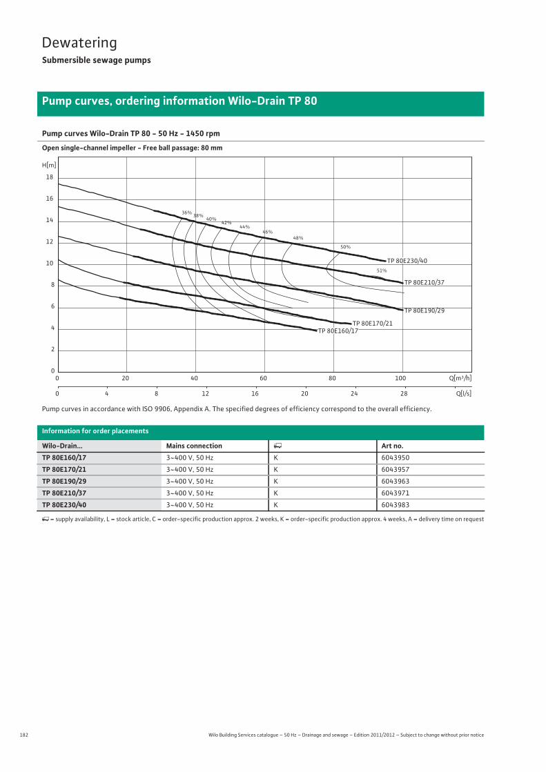
182 Wilo Building Services catalogue – 50 Hz – Drainage and sewage – Edition 2011/2012 – Subject to change without prior notice
DewateringSubmersible sewage pumps
Pump curves, ordering information Wilo-Drain TP 80
Pump curves Wilo-Drain TP 80 - 50 Hz - 1450 rpm
Open single-channel impeller - Free ball passage: 80 mm
Pump curves in accordance with ISO 9906, Appendix A. The specified degrees of efficiency correspond to the overall efficiency.
Information for order placements
Wilo-Drain... Mains connection � Art no.TP 80E160/17 3~400 V, 50 Hz K 6043950
TP 80E170/21 3~400 V, 50 Hz K 6043957
TP 80E190/29 3~400 V, 50 Hz K 6043963
TP 80E210/37 3~400 V, 50 Hz K 6043971
TP 80E230/40 3~400 V, 50 Hz K 6043983
�= supply availability, L = stock article, C = order-specific production approx. 2 weeks, K = order-specific production approx. 4 weeks, A = delivery time on request
36% 38%40%
42%44%
46%48%
50%
51%
TP 80E210/37
TP 80E190/29
TP 80E170/21
Q[m³/h]0 20 40 60 80 100
Q[l/s]0 4 8 12 16 20 24 28
H[m]
0
2
4
6
8
10
12
14
16
18
TP 80E160/17
TP 80E230/40

183
DewateringSubmersible sewage pumps
Wilo Building Services catalogue – 50 Hz – Drainage and sewage – Edition 2011/2012 – Subject to change without prior notice
Technical data Drain TP 80
Dew
ater
ing
TP 80E160/17 TP 80E170/21 TP 80E190/29 TP 80E210/37 TP 80E230/403~400 V, 50 Hz 3~400 V, 50 Hz 3~400 V, 50 Hz 3~400 V, 50 Hz 3~400 V, 50 Hz
Unit
Pressure connection DN 80 DN 80 DN 80 DN 80 DN 80
Free ball passage mm 80 80 80 80 80
Max. volume flow Qmax / m3/h 75 85 100 100 95
Max. delivery head Hmax / m 9 10 13 15 17
Operating mode (immersed) S1S3-25%
S1S3-25%
S1S3-25%
S1S3-25%
S1S3-25%
Operating mode (non-immersed) S1S3-25%
S1S3-25%
S1S3-25%
S1S3-25%
S1S3-25%
Max. immersion depth m 20 20 20 20 20
Protection class IP 68 IP 68 IP 68 IP 68 IP 68
Fluid temperature T / °C +3 ... +40 +3 ... +40 +3 ... +40 +3 ... +40 +3 ... +40
Weight approx. m / kg 42 42 42 42 42
Motor data
Nominal current IN / A 6.4 6.7 7.3 8.5 9.5
Starting current IA / A – – – – –
Nominal motor power P2 / kW 1.7 2.1 2.9 3.7 4
Power consumption P1 / kW 2 2.5 3.3 4.5 5.1
Activation type Direct Direct Direct Direct Direct
Nominal speed n / rpm 1450 1450 1450 1450 1450
Insulation class F F F F F
Recommended switching frequency 1/h 20 20 20 20 20
Max. switching frequency 1/h 60 60 60 60 60
Permitted voltage tolerance % +/- 10 +/- 10 +/- 10 +/- 10 +/- 10
Cable
Length of connecting cable m 10 10 10 10 10
Cable type NSSHÖU NSSHÖU NSSHÖU NSSHÖU NSSHÖU
Cable cross-section mm2 7x1,5 7x1,5 7x1,5 7x1,5 7x1,5
Type of connecting cable Detachable Detachable Detachable Detachable Detachable
Mains plug – – – – –
Equipment/function
Float switch – – – – –
Motor protection WSK WSK WSK WSK WSK
Explosion protection ATEX ATEX ATEX ATEX ATEX
Materials
Static seal NBR NBR NBR NBR NBR
Impeller PUR PUR PUR PUR PUR
Sealing on motor side C/Cr C/Cr C/Cr C/Cr C/Cr
Mechanical seal SiC/SiC SiC/SiC SiC/SiC SiC/SiC SiC/SiC
Motor housing 1.4404 1.4404 1.4404 1.4404 1.4404
Pump housing PUR PUR PUR PUR PUR
Pump shaft 1.4404 1.4404 1.4404 1.4404 1.4404
P1 refers to the maximum power consumption. All of the data applies to 3~400 V, 50 Hz and a density of 1 kg/dm3.
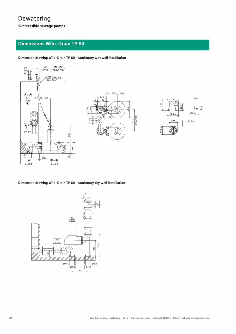
184 Wilo Building Services catalogue – 50 Hz – Drainage and sewage – Edition 2011/2012 – Subject to change without prior notice
DewateringSubmersible sewage pumps
Dimensions Wilo-Drain TP 80
Dimension drawing Wilo-Drain TP 80 - stationary wet well installation
Dimension drawing Wilo-Drain TP 80 - stationary dry well installation
19
200 160
DN 80
90 60 14
15
40
228
688
>85
700x1200
ø1500 ø1200
300 325
ø650
Ø12
81 146
315
180
80
300
>80
2x Ø42,4x3,25 DIN 2440
228
428
200
615
(550
-750
)
52
81
14 220
200
170
170
14
210,5
225 118,5
303,4
300
180
110
105
Ø40
+
+
+
494
370
180 180 130 130
342
140
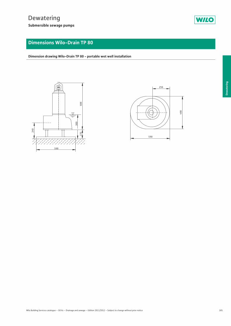
185
DewateringSubmersible sewage pumps
Dew
ater
ing
Dimensions Wilo-Drain TP 80
Wilo Building Services catalogue – 50 Hz – Drainage and sewage – Edition 2011/2012 – Subject to change without prior notice
Dimension drawing Wilo-Drain TP 80 - portable wet well installation
256
590
490
135
300
688
240
590
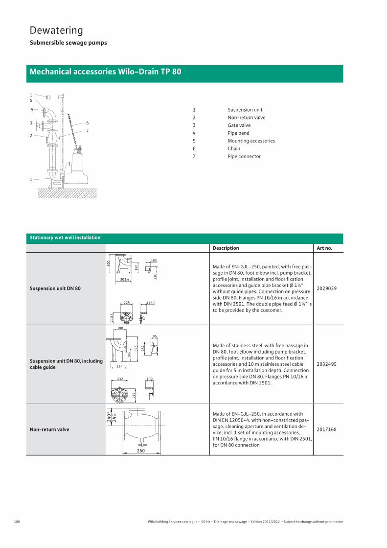
186 Wilo Building Services catalogue – 50 Hz – Drainage and sewage – Edition 2011/2012 – Subject to change without prior notice
DewateringSubmersible sewage pumps
Mechanical accessories Wilo-Drain TP 80
Stationary wet well installation
Description Art no.
Suspension unit DN 80
Made of EN-GJL-250, painted, with free pas-sage in DN 80, foot elbow incl. pump bracket, profile joint, installation and floor fixationaccessories and guide pipe bracket Ø 1¼" without guide pipes. Connection on pressure side DN 80. Flanges PN 10/16 in accordance with DIN 2501. The double pipe feed Ø 1¼" is to be provided by the customer.
2029039
Suspension unit DN 80, including cable guide
Made of stainless steel, with free passage in DN 80, foot elbow including pump bracket, profile joint, installation and floor fixationaccessories and 10 m stainless steel cable guide for 5 m installation depth. Connection on pressure side DN 80. Flanges PN 10/16 in accordance with DIN 2501.
2032495
Non-return valve
Made of EN-GJL-250, in accordance with DIN EN 12050-4, with non-constricted pas-sage, cleaning aperture and ventilation de-vice, incl. 1 set of mounting accessories, PN 10/16 flange in accordance with DIN 2501, for DN 80 connection
2017168
5
1
4
3
2
1
6
7
1
1 Suspension unit2 Non-return valve3 Gate valve4 Pipe bend5 Mounting accessories6 Chain7 Pipe connector
118,5225
303,4
210,5
300
180
110
105
180
185
182
345
217
211
232 109
95
240*
245
260
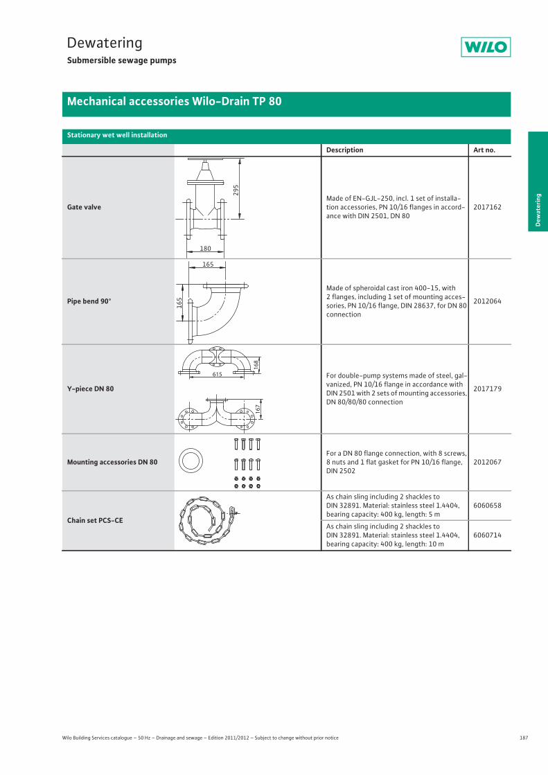
187
DewateringSubmersible sewage pumps
Dew
ater
ing
Mechanical accessories Wilo-Drain TP 80
Wilo Building Services catalogue – 50 Hz – Drainage and sewage – Edition 2011/2012 – Subject to change without prior notice
Gate valveMade of EN-GJL-250, incl. 1 set of installa-tion accessories, PN 10/16 flanges in accord-ance with DIN 2501, DN 80
2017162
Pipe bend 90°
Made of spheroidal cast iron 400-15, with2 flanges, including 1 set of mounting acces-sories, PN 10/16 flange, DIN 28637, for DN 80 connection
2012064
Y-piece DN 80
For double-pump systems made of steel, gal-vanized, PN 10/16 flange in accordance with DIN 2501 with 2 sets of mounting accessories, DN 80/80/80 connection
2017179
Mounting accessories DN 80For a DN 80 flange connection, with 8 screws, 8 nuts and 1 flat gasket for PN 10/16 flange, DIN 2502
2012067
Chain set PCS-CE
As chain sling including 2 shackles to DIN 32891. Material: stainless steel 1.4404, bearing capacity: 400 kg, length: 5 m
6060658
As chain sling including 2 shackles to DIN 32891. Material: stainless steel 1.4404, bearing capacity: 400 kg, length: 10 m
6060714
Stationary wet well installation
Description Art no.
295
180
165
165
167
615
168
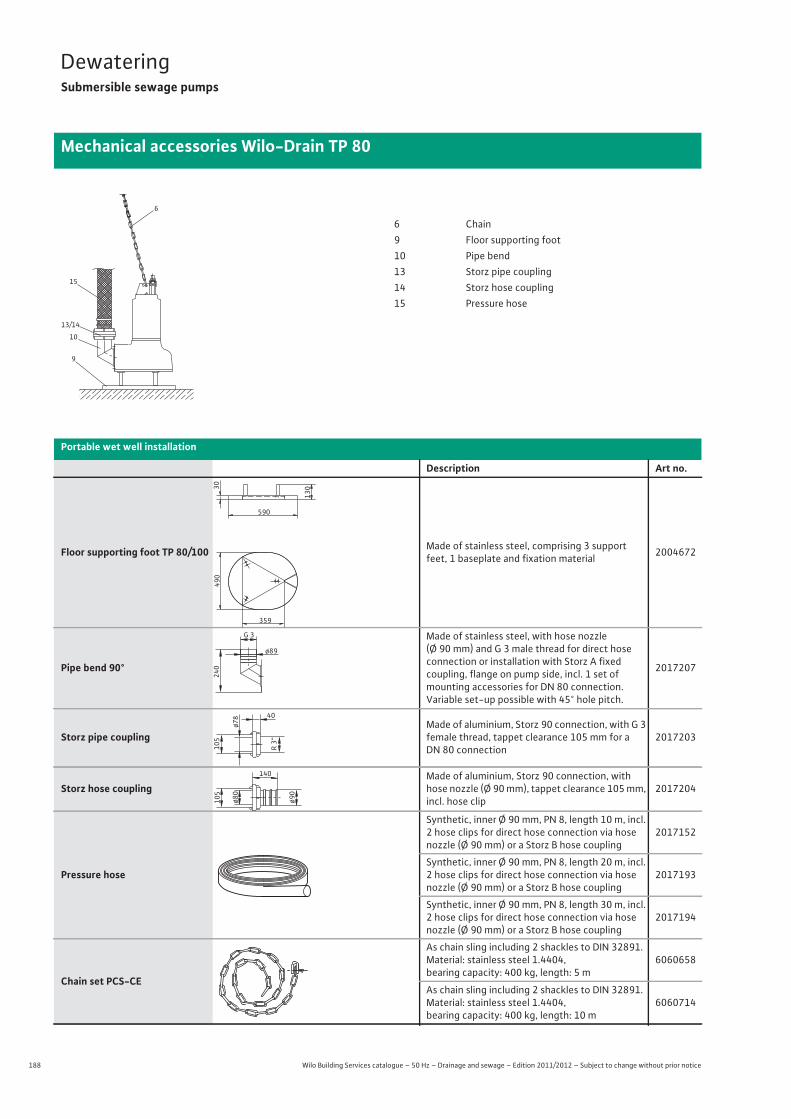
188 Wilo Building Services catalogue – 50 Hz – Drainage and sewage – Edition 2011/2012 – Subject to change without prior notice
DewateringSubmersible sewage pumps
Mechanical accessories Wilo-Drain TP 80
6
15
10
13/14
9
6 Chain9 Floor supporting foot10 Pipe bend13 Storz pipe coupling14 Storz hose coupling15 Pressure hose
Portable wet well installation
Description Art no.
Floor supporting foot TP 80/100 Made of stainless steel, comprising 3 support feet, 1 baseplate and fixation material 2004672
Pipe bend 90°
Made of stainless steel, with hose nozzle (Ø 90 mm) and G 3 male thread for direct hose connection or installation with Storz A fixedcoupling, flange on pump side, incl. 1 set of mounting accessories for DN 80 connection.Variable set-up possible with 45° hole pitch.
2017207
Storz pipe couplingMade of aluminium, Storz 90 connection, with G 3 female thread, tappet clearance 105 mm for a DN 80 connection
2017203
Storz hose couplingMade of aluminium, Storz 90 connection, with hose nozzle (Ø 90 mm), tappet clearance 105 mm, incl. hose clip
2017204
Pressure hose
Synthetic, inner Ø 90 mm, PN 8, length 10 m, incl. 2 hose clips for direct hose connection via hose nozzle (Ø 90 mm) or a Storz B hose coupling
2017152
Synthetic, inner Ø 90 mm, PN 8, length 20 m, incl. 2 hose clips for direct hose connection via hose nozzle (Ø 90 mm) or a Storz B hose coupling
2017193
Synthetic, inner Ø 90 mm, PN 8, length 30 m, incl. 2 hose clips for direct hose connection via hose nozzle (Ø 90 mm) or a Storz B hose coupling
2017194
Chain set PCS-CE
As chain sling including 2 shackles to DIN 32891. Material: stainless steel 1.4404, bearing capacity: 400 kg, length: 5 m
6060658
As chain sling including 2 shackles to DIN 32891. Material: stainless steel 1.4404, bearing capacity: 400 kg, length: 10 m
6060714
359
490
590
30
130
G 3
240
ø89
105
ø78 40
R 3“
ø90
140
ø80
105
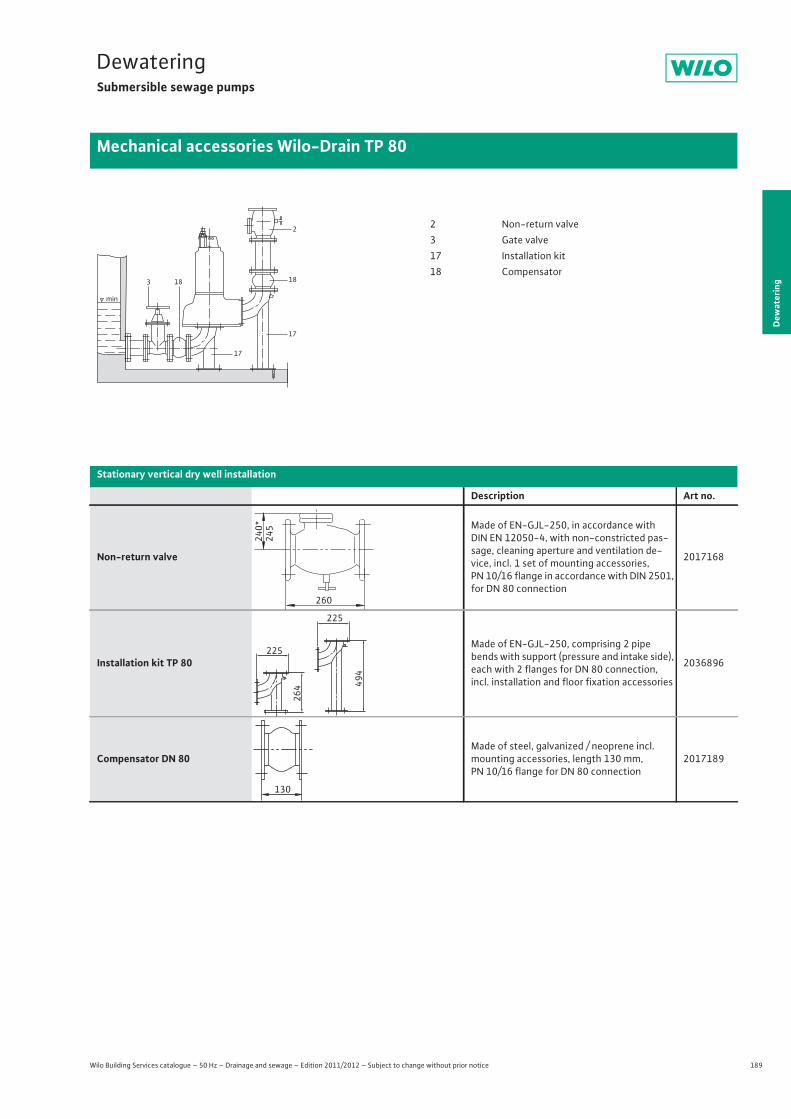
189
DewateringSubmersible sewage pumps
Dew
ater
ing
Mechanical accessories Wilo-Drain TP 80
Wilo Building Services catalogue – 50 Hz – Drainage and sewage – Edition 2011/2012 – Subject to change without prior notice
min
2
18
17
17
183
2 Non-return valve3 Gate valve17 Installation kit18 Compensator
Stationary vertical dry well installation
Description Art no.
Non-return valve
Made of EN-GJL-250, in accordance with DIN EN 12050-4, with non-constricted pas-sage, cleaning aperture and ventilation de-vice, incl. 1 set of mounting accessories, PN 10/16 flange in accordance with DIN 2501, for DN 80 connection
2017168
Installation kit TP 80
Made of EN-GJL-250, comprising 2 pipe bends with support (pressure and intake side), each with 2 flanges for DN 80 connection, incl. installation and floor fixation accessories
2036896
Compensator DN 80Made of steel, galvanized / neoprene incl. mounting accessories, length 130 mm, PN 10/16 flange for DN 80 connection
2017189
240*
245
260
225
225
494
264
130
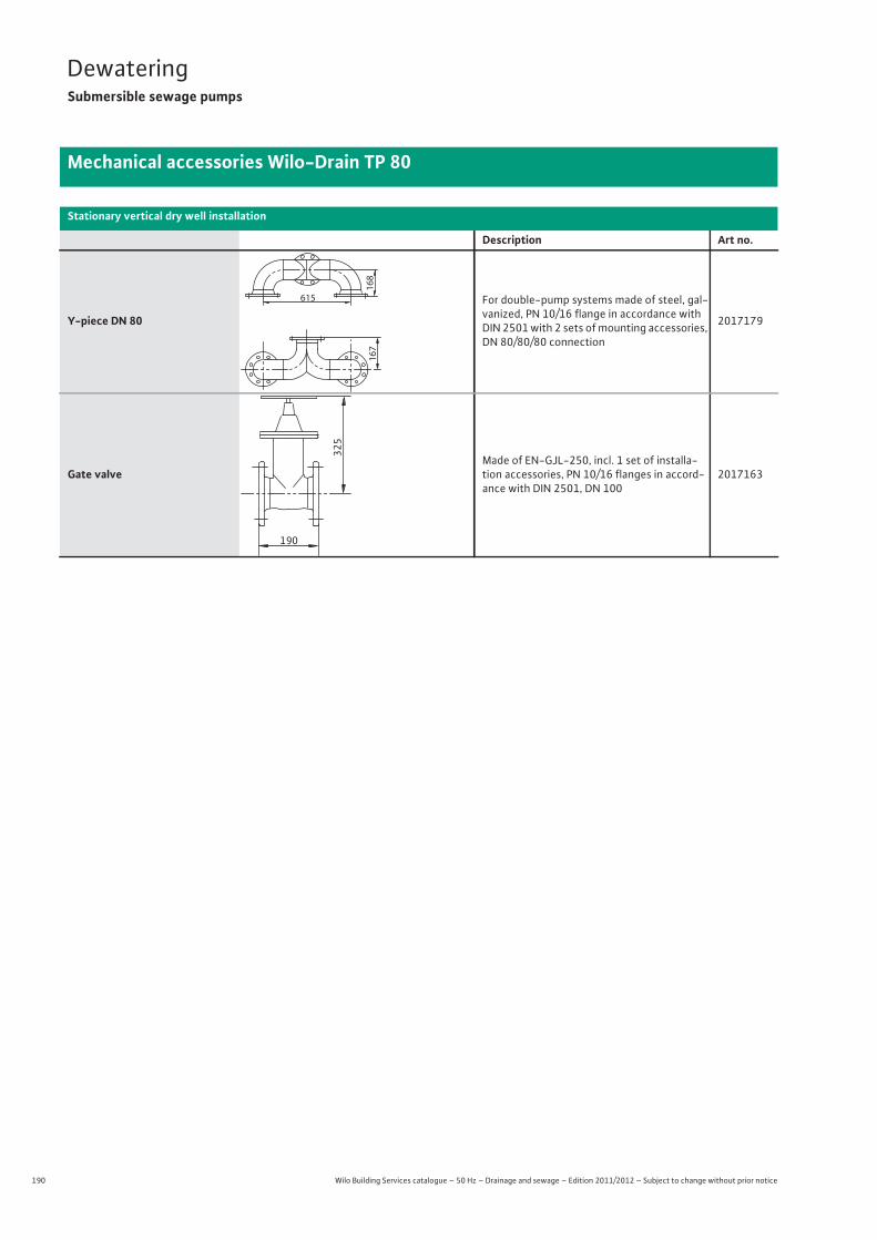
190 Wilo Building Services catalogue – 50 Hz – Drainage and sewage – Edition 2011/2012 – Subject to change without prior notice
DewateringSubmersible sewage pumps
Mechanical accessories Wilo-Drain TP 80
Y-piece DN 80
For double-pump systems made of steel, gal-vanized, PN 10/16 flange in accordance with DIN 2501 with 2 sets of mounting accessories, DN 80/80/80 connection
2017179
Gate valveMade of EN-GJL-250, incl. 1 set of installa-tion accessories, PN 10/16 flanges in accord-ance with DIN 2501, DN 100
2017163
Stationary vertical dry well installation
Description Art no.
167
615
168
325
190
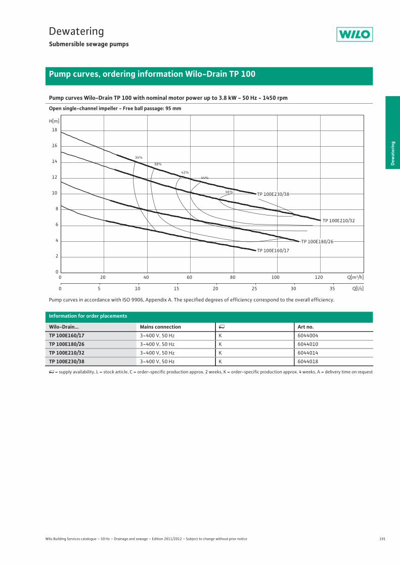
191
DewateringSubmersible sewage pumps
Dew
ater
ing
Pump curves, ordering information Wilo-Drain TP 100
Wilo Building Services catalogue – 50 Hz – Drainage and sewage – Edition 2011/2012 – Subject to change without prior notice
Pump curves Wilo-Drain TP 100 with nominal motor power up to 3.8 kW - 50 Hz - 1450 rpm
Open single-channel impeller - Free ball passage: 95 mm
Pump curves in accordance with ISO 9906, Appendix A. The specified degrees of efficiency correspond to the overall efficiency.
Information for order placements
Wilo-Drain... Mains connection � Art no.TP 100E160/17 3~400 V, 50 Hz K 6044004
TP 100E180/26 3~400 V, 50 Hz K 6044010
TP 100E210/32 3~400 V, 50 Hz K 6044014
TP 100E230/38 3~400 V, 50 Hz K 6044018
�= supply availability, L = stock article, C = order-specific production approx. 2 weeks, K = order-specific production approx. 4 weeks, A = delivery time on request
34%
38%
42%44%
46%
TP 100E210/32
Q[m³/h]0 20 40 60 80 100 120
Q[l/s]0 5 10 15 20 25 30 35
H[m]
0
2
4
6
8
10
12
14
16
18
TP 100E230/38
TP 100E180/26
TP 100E160/17

192 Wilo Building Services catalogue – 50 Hz – Drainage and sewage – Edition 2011/2012 – Subject to change without prior notice
DewateringSubmersible sewage pumps
Technical data Drain TP 100
TP 100E160/17 TP 100E180/26 TP 100E210/32 TP 100E230/383~400 V, 50 Hz 3~400 V, 50 Hz 3~400 V, 50 Hz 3~400 V, 50 Hz
Unit
Pressure connection DN 100 DN 100 DN 100 DN 100
Free ball passage mm 95 95 95 95
Max. volume flow Qmax / m3/h 90 110 120 90
Max. delivery head Hmax / m 8 11 15 18
Operating mode (immersed) S1S3-25%
S1S3-25%
S1S3-25%
S1S3-25%
Operating mode (non-immersed) S1S3-25%
S1S3-25%
S1S3-25%
S1S3-25%
Max. immersion depth m 20 20 20 20
Protection class IP 68 IP 68 IP 68 IP 68
Fluid temperature T / °C +3 ... +40 +3 ... +40 +3 ... +40 +3 ... +40
Weight approx. m / kg 43 43 43 43
Motor data
Nominal current IN / A 6.6 7.5 9 9.5
Starting current IA / A – – – –
Nominal motor power P2 / kW 1.7 2.6 3.2 3.8
Power consumption P1 / kW 2.1 3.4 4.8 5.2
Activation type Direct Direct Direct Direct
Nominal speed n / rpm 1450 1450 1450 1450
Insulation class F F F F
Recommended switching frequency 1/h 20 20 20 20
Max. switching frequency 1/h 60 60 60 60
Permitted voltage tolerance % +/- 10 +/- 10 +/- 10 +/- 10
Cable
Length of connecting cable m 10 10 10 10
Cable type NSSHÖU NSSHÖU NSSHÖU NSSHÖU
Cable cross-section mm2 7x1,5 7x1,5 7x1,5 7x1,5
Type of connecting cable Detachable Detachable Detachable Detachable
Mains plug – – – –
Equipment/function
Float switch – – – –
Motor protection WSK WSK WSK WSK
Explosion protection ATEX ATEX ATEX ATEX
Materials
Static seal NBR NBR NBR NBR
Impeller PUR PUR PUR PUR
Sealing on motor side C/Cr C/Cr C/Cr C/Cr
Mechanical seal SiC/SiC SiC/SiC SiC/SiC SiC/SiC
Motor housing 1.4404 1.4404 1.4404 1.4404
Pump housing PUR PUR PUR PUR
Pump shaft 1.4404 1.4404 1.4404 1.4404
P1 refers to the maximum power consumption. All of the data applies to 3~400 V, 50 Hz and a density of 1 kg/dm3.
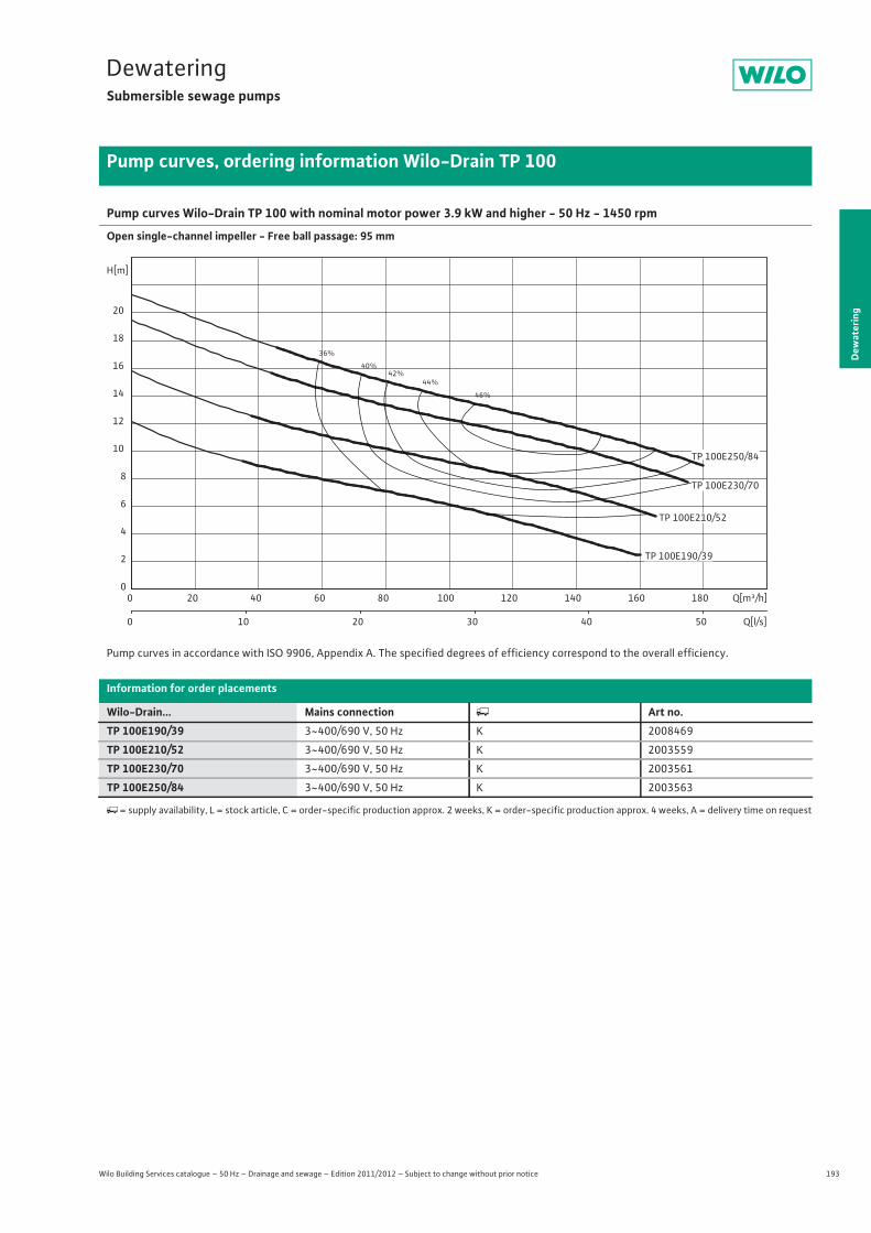
193
DewateringSubmersible sewage pumps
Dew
ater
ing
Pump curves, ordering information Wilo-Drain TP 100
Wilo Building Services catalogue – 50 Hz – Drainage and sewage – Edition 2011/2012 – Subject to change without prior notice
Pump curves Wilo-Drain TP 100 with nominal motor power 3.9 kW and higher - 50 Hz - 1450 rpm
Open single-channel impeller - Free ball passage: 95 mm
Pump curves in accordance with ISO 9906, Appendix A. The specified degrees of efficiency correspond to the overall efficiency.
Information for order placements
Wilo-Drain... Mains connection � Art no.TP 100E190/39 3~400/690 V, 50 Hz K 2008469
TP 100E210/52 3~400/690 V, 50 Hz K 2003559
TP 100E230/70 3~400/690 V, 50 Hz K 2003561
TP 100E250/84 3~400/690 V, 50 Hz K 2003563
�= supply availability, L = stock article, C = order-specific production approx. 2 weeks, K = order-specific production approx. 4 weeks, A = delivery time on request
36%
40%42%
44%
46%
Q[m³/h]0 20 40 60 80 100 120 140 160 180
Q[l/s]0 10 20 30 40 50
H[m]
0
2
4
6
8
10
12
14
16
18
20
TP 100E230/70
TP 100E250/84
TP 100E210/52
TP 100E190/39
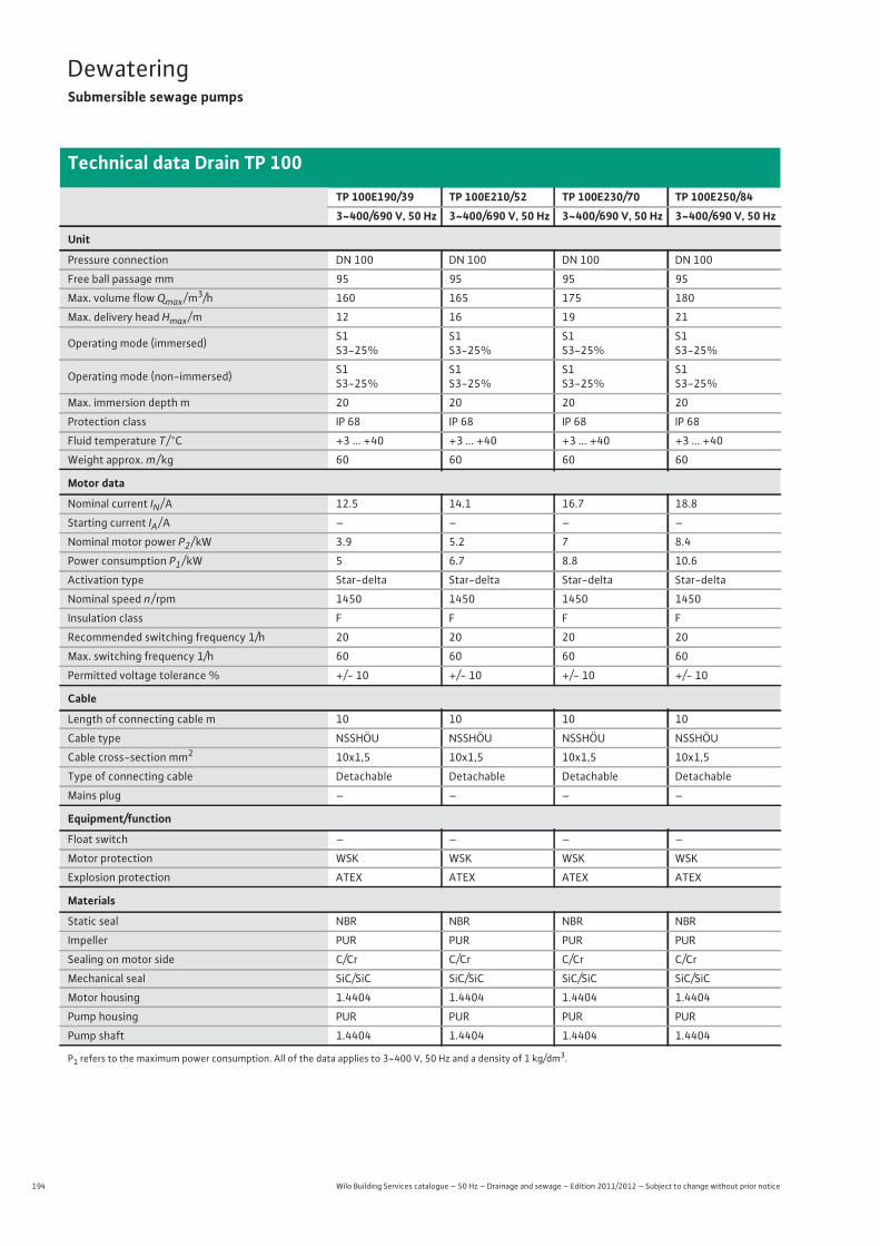
194 Wilo Building Services catalogue – 50 Hz – Drainage and sewage – Edition 2011/2012 – Subject to change without prior notice
DewateringSubmersible sewage pumps
Technical data Drain TP 100
TP 100E190/39 TP 100E210/52 TP 100E230/70 TP 100E250/843~400/690 V, 50 Hz 3~400/690 V, 50 Hz 3~400/690 V, 50 Hz 3~400/690 V, 50 Hz
Unit
Pressure connection DN 100 DN 100 DN 100 DN 100
Free ball passage mm 95 95 95 95
Max. volume flow Qmax / m3/h 160 165 175 180
Max. delivery head Hmax / m 12 16 19 21
Operating mode (immersed) S1S3-25%
S1S3-25%
S1S3-25%
S1S3-25%
Operating mode (non-immersed) S1S3-25%
S1S3-25%
S1S3-25%
S1S3-25%
Max. immersion depth m 20 20 20 20
Protection class IP 68 IP 68 IP 68 IP 68
Fluid temperature T / °C +3 ... +40 +3 ... +40 +3 ... +40 +3 ... +40
Weight approx. m / kg 60 60 60 60
Motor data
Nominal current IN / A 12.5 14.1 16.7 18.8
Starting current IA / A – – – –
Nominal motor power P2 / kW 3.9 5.2 7 8.4
Power consumption P1 / kW 5 6.7 8.8 10.6
Activation type Star-delta Star-delta Star-delta Star-delta
Nominal speed n / rpm 1450 1450 1450 1450
Insulation class F F F F
Recommended switching frequency 1/h 20 20 20 20
Max. switching frequency 1/h 60 60 60 60
Permitted voltage tolerance % +/- 10 +/- 10 +/- 10 +/- 10
Cable
Length of connecting cable m 10 10 10 10
Cable type NSSHÖU NSSHÖU NSSHÖU NSSHÖU
Cable cross-section mm2 10x1,5 10x1,5 10x1,5 10x1,5
Type of connecting cable Detachable Detachable Detachable Detachable
Mains plug – – – –
Equipment/function
Float switch – – – –
Motor protection WSK WSK WSK WSK
Explosion protection ATEX ATEX ATEX ATEX
Materials
Static seal NBR NBR NBR NBR
Impeller PUR PUR PUR PUR
Sealing on motor side C/Cr C/Cr C/Cr C/Cr
Mechanical seal SiC/SiC SiC/SiC SiC/SiC SiC/SiC
Motor housing 1.4404 1.4404 1.4404 1.4404
Pump housing PUR PUR PUR PUR
Pump shaft 1.4404 1.4404 1.4404 1.4404
P1 refers to the maximum power consumption. All of the data applies to 3~400 V, 50 Hz and a density of 1 kg/dm3.
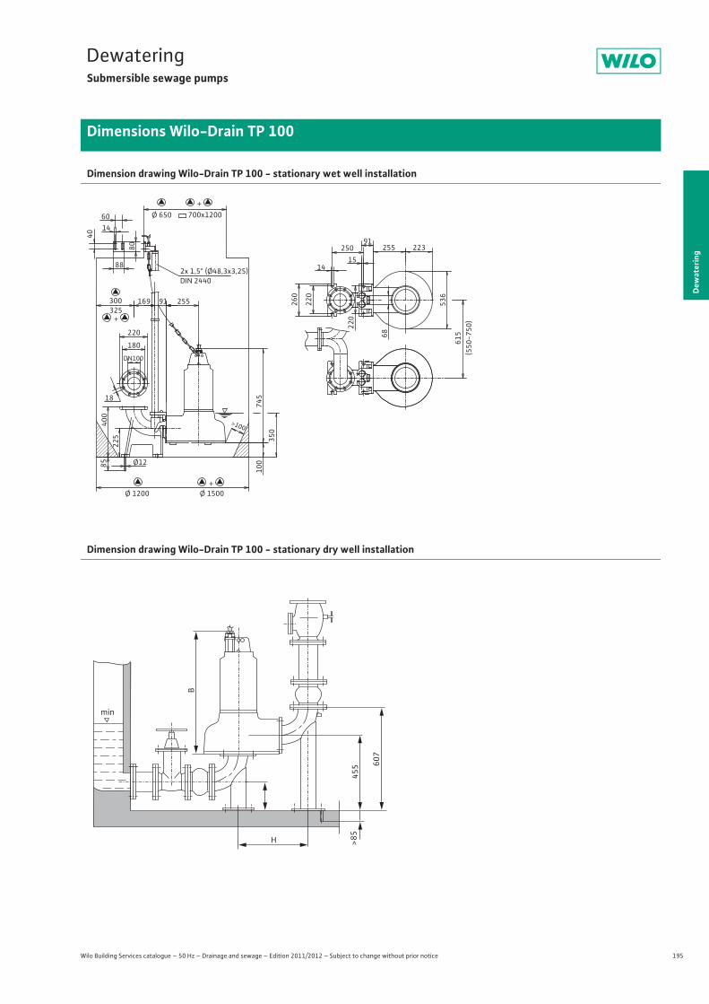
195
DewateringSubmersible sewage pumps
Dew
ater
ing
Dimensions Wilo-Drain TP 100
Wilo Building Services catalogue – 50 Hz – Drainage and sewage – Edition 2011/2012 – Subject to change without prior notice
Dimension drawing Wilo-Drain TP 100 - stationary wet well installation
Dimension drawing Wilo-Drain TP 100 - stationary dry well installation
91 250
15
615
91 169
60
40
80
88
260
220
14
220
223 255
536
745
>100
350
14
Ø12 85
220
180
225
18
(550
-750
)
Ø 650 700x1200
Ø 1500 Ø 1200
300 325
2x 1,5" (Ø48,3x3,25)DIN 2440
400
255
100
68
DN100
+
+
+
min
H
B
455
>85
607
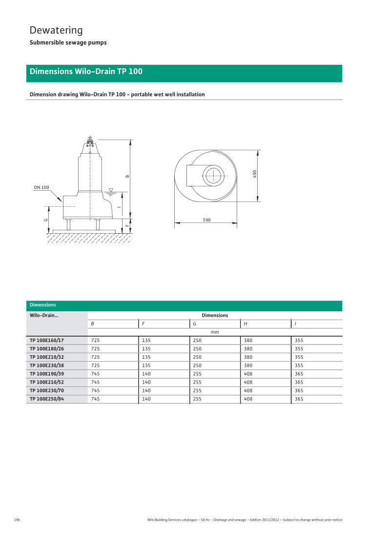
196 Wilo Building Services catalogue – 50 Hz – Drainage and sewage – Edition 2011/2012 – Subject to change without prior notice
DewateringSubmersible sewage pumps
Dimensions Wilo-Drain TP 100
Dimension drawing Wilo-Drain TP 100 - portable wet well installation
Dimensions
Wilo-Drain... DimensionsB F G H I
mm
TP 100E160/17 725 135 250 380 355
TP 100E180/26 725 135 250 380 355
TP 100E210/32 725 135 250 380 355
TP 100E230/38 725 135 250 380 355
TP 100E190/39 745 140 255 408 365
TP 100E210/52 745 140 255 408 365
TP 100E230/70 745 140 255 408 365
TP 100E250/84 745 140 255 408 365
FB
I
G 590
490
DN 100
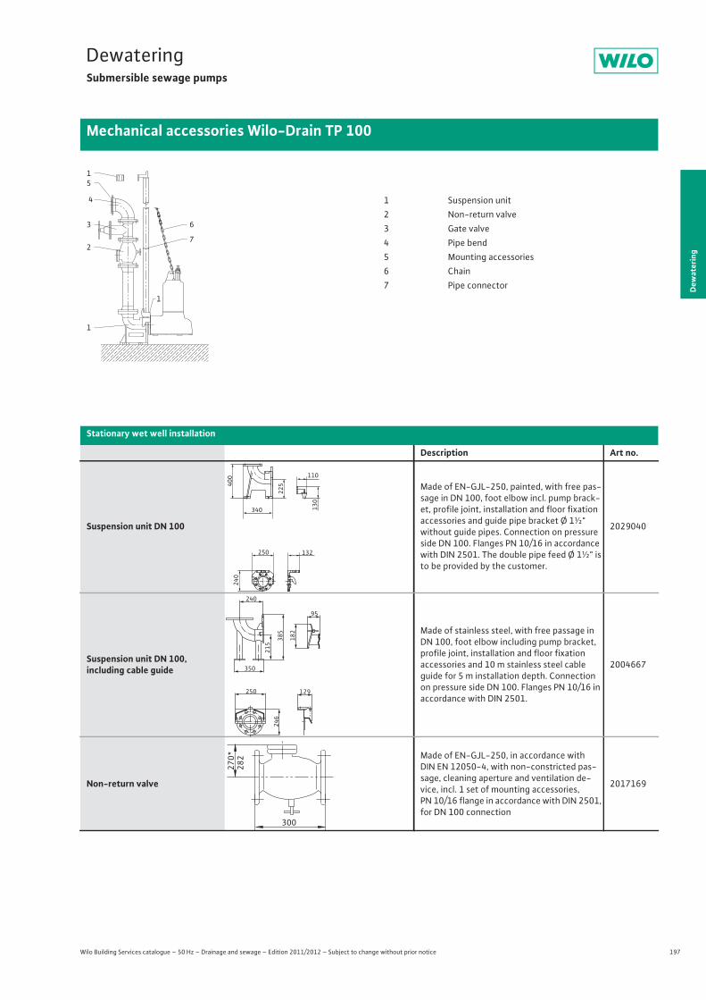
197
DewateringSubmersible sewage pumps
Dew
ater
ing
Mechanical accessories Wilo-Drain TP 100
Wilo Building Services catalogue – 50 Hz – Drainage and sewage – Edition 2011/2012 – Subject to change without prior notice
Stationary wet well installation
Description Art no.
Suspension unit DN 100
Made of EN-GJL-250, painted, with free pas-sage in DN 100, foot elbow incl. pump brack-et, profile joint, installation and floor fixation accessories and guide pipe bracket Ø 1½" without guide pipes. Connection on pressure side DN 100. Flanges PN 10/16 in accordance with DIN 2501. The double pipe feed Ø 1½" is to be provided by the customer.
2029040
Suspension unit DN 100,including cable guide
Made of stainless steel, with free passage in DN 100, foot elbow including pump bracket, profile joint, installation and floor fixationaccessories and 10 m stainless steel cable guide for 5 m installation depth. Connection on pressure side DN 100. Flanges PN 10/16 in accordance with DIN 2501.
2004667
Non-return valve
Made of EN-GJL-250, in accordance with DIN EN 12050-4, with non-constricted pas-sage, cleaning aperture and ventilation de-vice, incl. 1 set of mounting accessories, PN 10/16 flange in accordance with DIN 2501, for DN 100 connection
2017169
5
1
4
3
2
1
6
7
1
1 Suspension unit2 Non-return valve3 Gate valve4 Pipe bend5 Mounting accessories6 Chain7 Pipe connector
132 250
340
240
400
225
130
110
240
215
182
385
350
246
250 129
95
270*
282
300
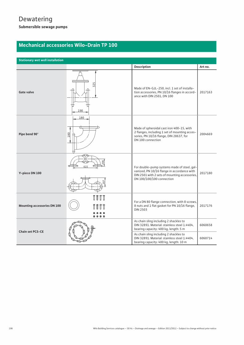
198 Wilo Building Services catalogue – 50 Hz – Drainage and sewage – Edition 2011/2012 – Subject to change without prior notice
DewateringSubmersible sewage pumps
Mechanical accessories Wilo-Drain TP 100
Gate valveMade of EN-GJL-250, incl. 1 set of installa-tion accessories, PN 10/16 flanges in accord-ance with DIN 2501, DN 100
2017163
Pipe bend 90°
Made of spheroidal cast iron 400-15, with2 flanges, including 1 set of mounting acces-sories, PN 10/16 flange, DIN 28637, forDN 100 connection
2004669
Y-piece DN 100
For double-pump systems made of steel, gal-vanized, PN 10/16 flange in accordance with DIN 2501 with 2 sets of mounting accessories, DN 100/100/100 connection
2017180
Mounting accessories DN 100For a DN 80 flange connection, with 8 screws, 8 nuts and 1 flat gasket for PN 10/16 flange, DIN 2503
2017176
Chain set PCS-CE
As chain sling including 2 shackles to DIN 32891. Material: stainless steel 1.4404, bearing capacity: 400 kg, length: 5 m
6060658
As chain sling including 2 shackles to DIN 32891. Material: stainless steel 1.4404, bearing capacity: 400 kg, length: 10 m
6060714
Stationary wet well installation
Description Art no.
325
190
180
180
207
615
208
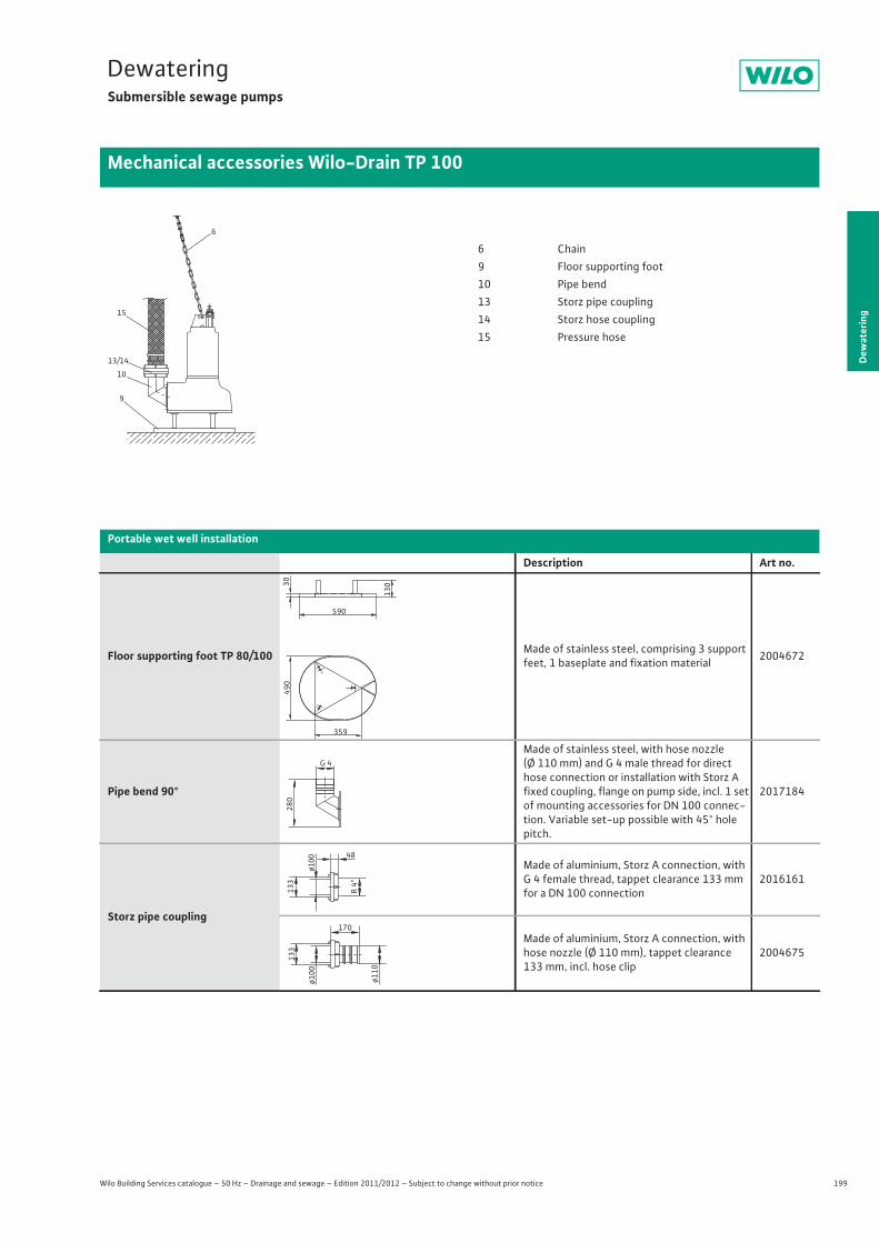
199
DewateringSubmersible sewage pumps
Dew
ater
ing
Mechanical accessories Wilo-Drain TP 100
Wilo Building Services catalogue – 50 Hz – Drainage and sewage – Edition 2011/2012 – Subject to change without prior notice
Portable wet well installation
Description Art no.
Floor supporting foot TP 80/100 Made of stainless steel, comprising 3 support feet, 1 baseplate and fixation material 2004672
Pipe bend 90°
Made of stainless steel, with hose nozzle (Ø 110 mm) and G 4 male thread for direct hose connection or installation with Storz A fixed coupling, flange on pump side, incl. 1 set of mounting accessories for DN 100 connec-tion. Variable set-up possible with 45° hole pitch.
2017184
Storz pipe coupling
Made of aluminium, Storz A connection, with G 4 female thread, tappet clearance 133 mm for a DN 100 connection
2016161
Made of aluminium, Storz A connection, with hose nozzle (Ø 110 mm), tappet clearance 133 mm, incl. hose clip
2004675
6
15
10
13/14
9
6 Chain9 Floor supporting foot10 Pipe bend13 Storz pipe coupling14 Storz hose coupling15 Pressure hose
359
490
590
30
130
G 4
280
133
ø100 48
R 4“
ø110
170
ø100
133
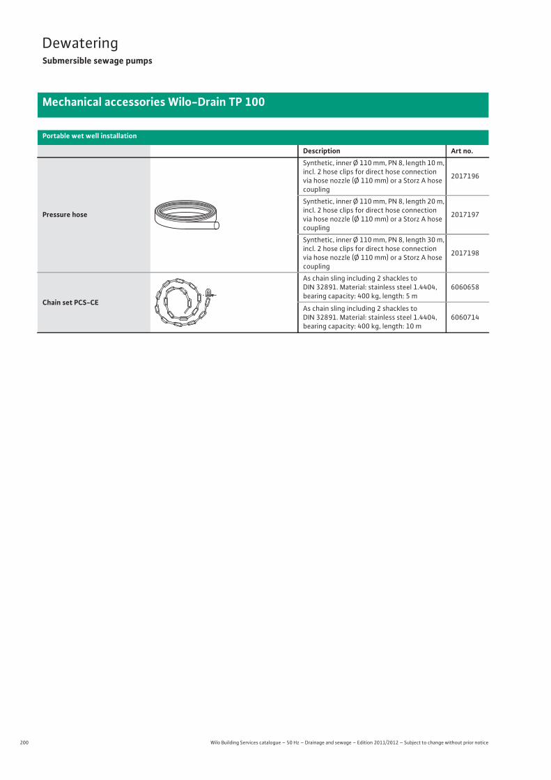
200 Wilo Building Services catalogue – 50 Hz – Drainage and sewage – Edition 2011/2012 – Subject to change without prior notice
DewateringSubmersible sewage pumps
Mechanical accessories Wilo-Drain TP 100
Pressure hose
Synthetic, inner Ø 110 mm, PN 8, length 10 m, incl. 2 hose clips for direct hose connection via hose nozzle (Ø 110 mm) or a Storz A hose coupling
2017196
Synthetic, inner Ø 110 mm, PN 8, length 20 m, incl. 2 hose clips for direct hose connection via hose nozzle (Ø 110 mm) or a Storz A hose coupling
2017197
Synthetic, inner Ø 110 mm, PN 8, length 30 m, incl. 2 hose clips for direct hose connection via hose nozzle (Ø 110 mm) or a Storz A hose coupling
2017198
Chain set PCS-CE
As chain sling including 2 shackles to DIN 32891. Material: stainless steel 1.4404, bearing capacity: 400 kg, length: 5 m
6060658
As chain sling including 2 shackles to DIN 32891. Material: stainless steel 1.4404, bearing capacity: 400 kg, length: 10 m
6060714
Portable wet well installation
Description Art no.
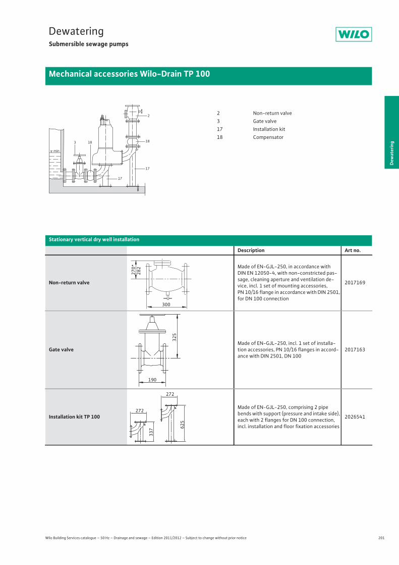
201
DewateringSubmersible sewage pumps
Dew
ater
ing
Mechanical accessories Wilo-Drain TP 100
Wilo Building Services catalogue – 50 Hz – Drainage and sewage – Edition 2011/2012 – Subject to change without prior notice
min
2
18
17
17
183
2 Non-return valve3 Gate valve17 Installation kit18 Compensator
Stationary vertical dry well installation
Description Art no.
Non-return valve
Made of EN-GJL-250, in accordance with DIN EN 12050-4, with non-constricted pas-sage, cleaning aperture and ventilation de-vice, incl. 1 set of mounting accessories, PN 10/16 flange in accordance with DIN 2501, for DN 100 connection
2017169
Gate valveMade of EN-GJL-250, incl. 1 set of installa-tion accessories, PN 10/16 flanges in accord-ance with DIN 2501, DN 100
2017163
Installation kit TP 100
Made of EN-GJL-250, comprising 2 pipe bends with support (pressure and intake side), each with 2 flanges for DN 100 connection, incl. installation and floor fixation accessories
2026541
270*
282
300
325
190
272
272
625
337
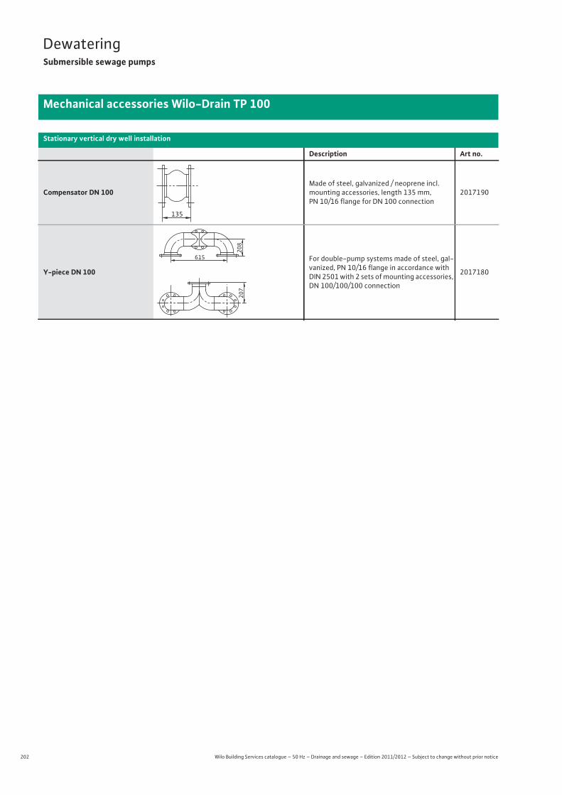
202 Wilo Building Services catalogue – 50 Hz – Drainage and sewage – Edition 2011/2012 – Subject to change without prior notice
DewateringSubmersible sewage pumps
Mechanical accessories Wilo-Drain TP 100
Compensator DN 100Made of steel, galvanized / neoprene incl. mounting accessories, length 135 mm, PN 10/16 flange for DN 100 connection
2017190
Y-piece DN 100
For double-pump systems made of steel, gal-vanized, PN 10/16 flange in accordance with DIN 2501 with 2 sets of mounting accessories, DN 100/100/100 connection
2017180
Stationary vertical dry well installation
Description Art no.
135
207
615
208
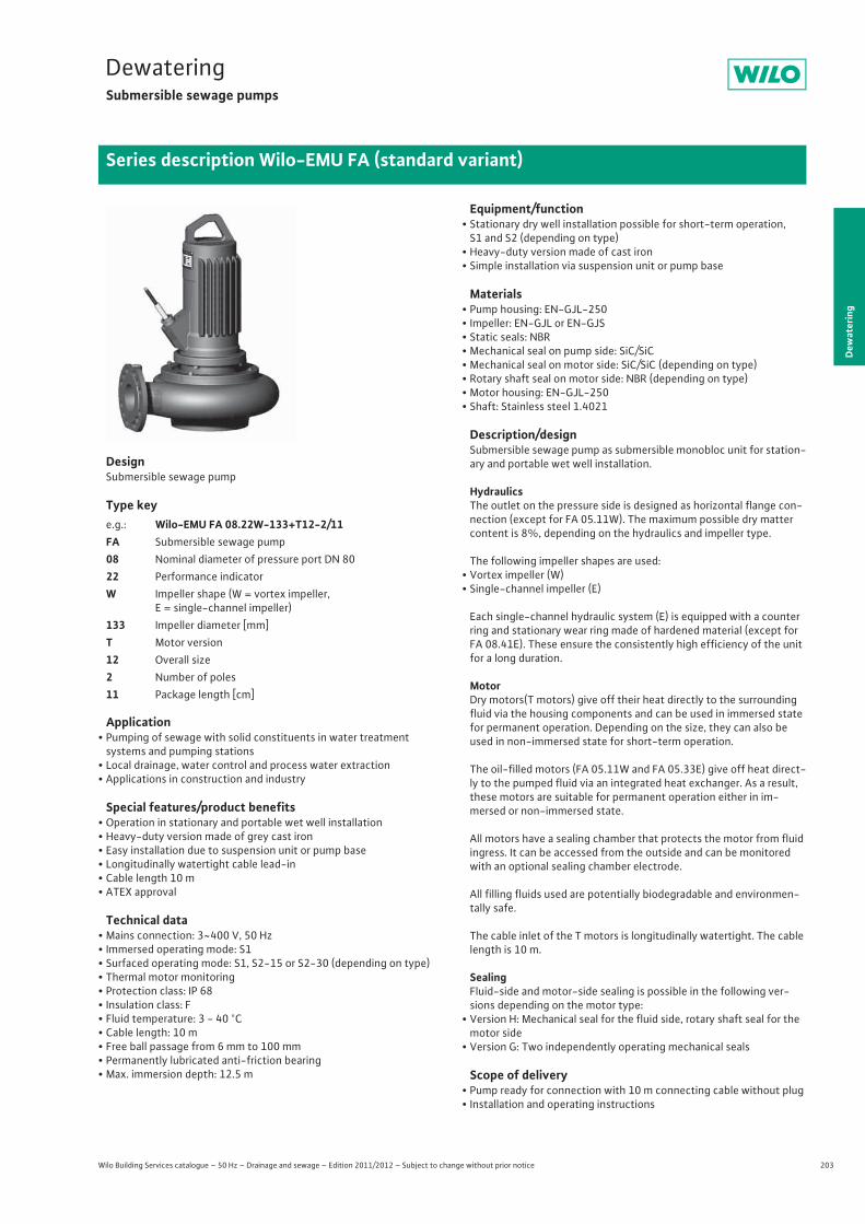
203
DewateringSubmersible sewage pumps
Dew
ater
ing
Series description Wilo-EMU FA (standard variant)
Wilo Building Services catalogue – 50 Hz – Drainage and sewage – Edition 2011/2012 – Subject to change without prior notice
DesignSubmersible sewage pump
Type key
Application• Pumping of sewage with solid constituents in water treatmentsystems and pumping stations
• Local drainage, water control and process water extraction• Applications in construction and industry
Special features/product benefits• Operation in stationary and portable wet well installation• Heavy-duty version made of grey cast iron• Easy installation due to suspension unit or pump base• Longitudinally watertight cable lead-in• Cable length 10 m• ATEX approval
Technical data• Mains connection: 3~400 V, 50 Hz• Immersed operating mode: S1• Surfaced operating mode: S1, S2-15 or S2-30 (depending on type)• Thermal motor monitoring• Protection class: IP 68• Insulation class: F• Fluid temperature: 3 - 40 °C• Cable length: 10 m• Free ball passage from 6 mm to 100 mm• Permanently lubricated anti-friction bearing• Max. immersion depth: 12.5 m
Equipment/function• Stationary dry well installation possible for short-term operation,S1 and S2 (depending on type)
• Heavy-duty version made of cast iron• Simple installation via suspension unit or pump base
Materials• Pump housing: EN-GJL-250• Impeller: EN-GJL or EN-GJS• Static seals: NBR• Mechanical seal on pump side: SiC/SiC• Mechanical seal on motor side: SiC/SiC (depending on type)• Rotary shaft seal on motor side: NBR (depending on type)• Motor housing: EN-GJL-250• Shaft: Stainless steel 1.4021
Description/designSubmersible sewage pump as submersible monobloc unit for station-ary and portable wet well installation.
HydraulicsThe outlet on the pressure side is designed as horizontal flange con-nection (except for FA 05.11W). The maximum possible dry matter content is 8%, depending on the hydraulics and impeller type.
The following impeller shapes are used:• Vortex impeller (W)• Single-channel impeller (E)
Each single-channel hydraulic system (E) is equipped with a counter ring and stationary wear ring made of hardened material (except for FA 08.41E). These ensure the consistently high efficiency of the unit for a long duration.
MotorDry motors(T motors) give off their heat directly to the surrounding fluid via the housing components and can be used in immersed state for permanent operation. Depending on the size, they can also be used in non-immersed state for short-term operation.
The oil-filled motors (FA 05.11W and FA 05.33E) give off heat direct-ly to the pumped fluid via an integrated heat exchanger. As a result, these motors are suitable for permanent operation either in im-mersed or non-immersed state.
All motors have a sealing chamber that protects the motor from fluid ingress. It can be accessed from the outside and can be monitored with an optional sealing chamber electrode.
All filling fluids used are potentially biodegradable and environmen-tally safe.
The cable inlet of the T motors is longitudinally watertight. The cable length is 10 m.
SealingFluid-side and motor-side sealing is possible in the following ver-sions depending on the motor type:
• Version H: Mechanical seal for the fluid side, rotary shaft seal for the motor side
• Version G: Two independently operating mechanical seals
Scope of delivery• Pump ready for connection with 10 m connecting cable without plug• Installation and operating instructions
e.g.: Wilo-EMU FA 08.22W-133+T12-2/11FA Submersible sewage pump08 Nominal diameter of pressure port DN 8022 Performance indicatorW Impeller shape (W = vortex impeller,
E = single-channel impeller)133 Impeller diameter [mm]T Motor version12 Overall size2 Number of poles11 Package length [cm]
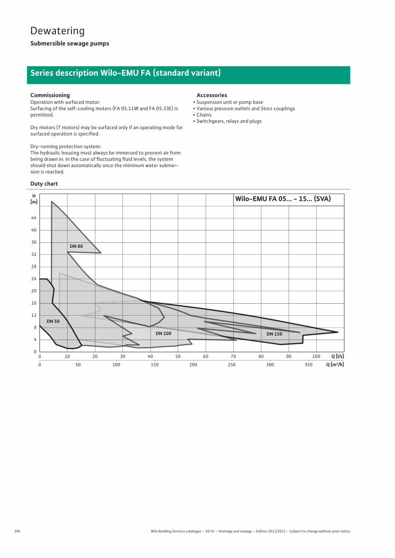
204 Wilo Building Services catalogue – 50 Hz – Drainage and sewage – Edition 2011/2012 – Subject to change without prior notice
DewateringSubmersible sewage pumps
Series description Wilo-EMU FA (standard variant)
CommissioningOperation with surfaced motor:Surfacing of the self-cooling motors (FA 05.11W and FA 05.33E) is permitted.
Dry motors (T motors) may be surfaced only if an operating mode for surfaced operation is specified.
Dry-running protection system:The hydraulic housing must always be immersed to prevent air from being drawn in. In the case of fluctuating fluid levels, the system should shut down automatically once the minimum water submer-sion is reached.
Accessories• Suspension unit or pump base• Various pressure outlets and Storz couplings• Chains• Switchgears, relays and plugs
Duty chart
0
0
10 20 30 40 50 60 70 80 90
50
100
100 150 200 250 300 350
Q [l/s]
4
8
12
16
20
24
0
40
36
32
28
44
H[m]
Q [m³/h]
DN 50
DN 80
DN 100 DN 150
Wilo-EMU FA 05... - 15... (SVA)
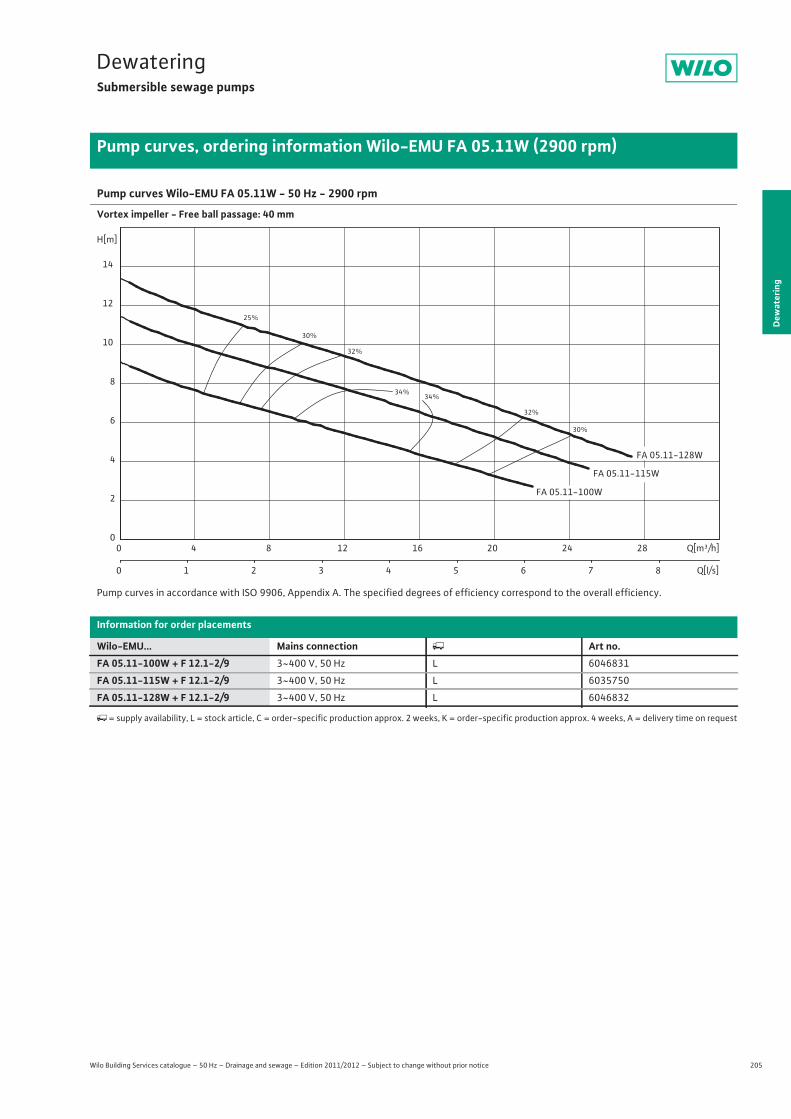
205
DewateringSubmersible sewage pumps
Dew
ater
ing
Pump curves, ordering information Wilo-EMU FA 05.11W (2900 rpm)
Wilo Building Services catalogue – 50 Hz – Drainage and sewage – Edition 2011/2012 – Subject to change without prior notice
Pump curves Wilo-EMU FA 05.11W - 50 Hz - 2900 rpm
Vortex impeller - Free ball passage: 40 mm
Pump curves in accordance with ISO 9906, Appendix A. The specified degrees of efficiency correspond to the overall efficiency.
Information for order placements
Wilo-EMU... Mains connection � Art no.FA 05.11-100W + F 12.1-2/9 3~400 V, 50 Hz L 6046831
FA 05.11-115W + F 12.1-2/9 3~400 V, 50 Hz L 6035750
FA 05.11-128W + F 12.1-2/9 3~400 V, 50 Hz L 6046832
�= supply availability, L = stock article, C = order-specific production approx. 2 weeks, K = order-specific production approx. 4 weeks, A = delivery time on request
25%
30%
30%
32%
32%
34%34%
FA 05.11-115W
FA 05.11-100W
FA 05.11-128W
Q[m³/h]0 4 8 12 16 20 24 28
Q[l/s]0 1 2 3 4 5 6 7 8
H[m]
0
2
4
6
8
10
12
14

206 Wilo Building Services catalogue – 50 Hz – Drainage and sewage – Edition 2011/2012 – Subject to change without prior notice
DewateringSubmersible sewage pumps
Technical data Wilo-EMU FA 05.11W (2900 rpm)
FA 05.11-100W + F 12.1-2/9 FA 05.11-115W + F 12.1-2/9 FA 05.11-128W + F 12.1-2/93~400 V, 50 Hz 3~400 V, 50 Hz 3~400 V, 50 Hz
Unit
Pressure connection G 2 G 2 G 2
Free ball passage mm 40 40 40
Max. volume flow Qmax / m3/h 22 25 27.3
Max. delivery head Hmax / m 9.1 11.5 13.4
Operating mode (immersed) S1 S1 S1
Operating mode (non-immersed) S1 S1 S1
Max. immersion depth m 12.5 12.5 12.5
Protection class IP 68 IP 68 IP 68
Fluid temperature T / °C +3 ... +40 +3 ... +40 +3 ... +40
Weight approx. m / kg 23 23 23
Motor data
Nominal current IN / A 3.15 3.15 3.15
Starting current IA / A 16 16 16
Nominal motor power P2 / kW 1.3 1.3 1.3
Power consumption P1 / kW 1.9 1.9 1.9
Activation type Direct Direct Direct
Nominal speed n / rpm 2850 2850 2850
Insulation class F F F
Recommended switching frequency 1/h – – –
Max. switching frequency 1/h 15 15 15
Permitted voltage tolerance % +/- 10 +/- 10 +/- 10
Cable
Length of connecting cable m 10 10 10
Cable type H07RN-F H07RN-F H07RN-F
Cable cross-section mm2 4G1,5 4G1,5 4G1,5
Type of connecting cable Non-detachable Non-detachable Non-detachable
Mains plug – – –
Equipment/function
Float switch – – –
Motor protection – – –
Explosion protection – – –
Materials
Static seal NBR NBR NBR
Impeller EN-GJL-250 EN-GJL-250 EN-GJL-250
Sealing on motor side Carbon/ceramic Carbon/ceramic Carbon/ceramic
Mechanical seal SiC/SiC SiC/SiC SiC/SiC
Motor housing EN-GJL-250 EN-GJL-250 EN-GJL-250
Pump housing EN-GJL-250 EN-GJL-250 EN-GJL-250
Pump shaft 1.4021 1.4021 1.4021
P1 refers to the maximum power consumption. All of the data applies to 3~400 V, 50 Hz and a density of 1 kg/dm3.
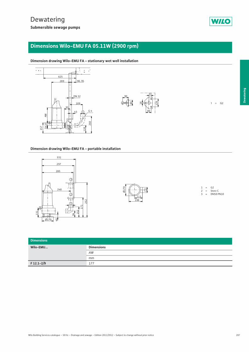
207
DewateringSubmersible sewage pumps
Dew
ater
ing
Dimensions Wilo-EMU FA 05.11W (2900 rpm)
Wilo Building Services catalogue – 50 Hz – Drainage and sewage – Edition 2011/2012 – Subject to change without prior notice
Dimension drawing Wilo-EMU FA - stationary wet well installation
Dimension drawing Wilo-EMU FA - portable installation
Dimensions
Wilo-EMU... DimensionsAW
mm
F 12.1-2/9 177
33
157
37
18 120
80
90
625
91
43
54
289 90, 95
260
120
109
DN 32
G 4
AW
801
1 = G2
131
40
1248
285
Ø170
94 152
171
252
297
331
Ø17
0
113198
1
2
3
1 = G22 = Storz C3 = DN50 PN10
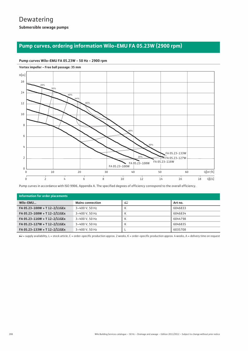
208 Wilo Building Services catalogue – 50 Hz – Drainage and sewage – Edition 2011/2012 – Subject to change without prior notice
DewateringSubmersible sewage pumps
Pump curves, ordering information Wilo-EMU FA 05.23W (2900 rpm)
Pump curves Wilo-EMU FA 05.23W - 50 Hz - 2900 rpm
Vortex impeller - Free ball passage: 35 mm
Pump curves in accordance with ISO 9906, Appendix A. The specified degrees of efficiency correspond to the overall efficiency.
Information for order placements
Wilo-EMU... Mains connection � Art no.FA 05.23-100W + T 12-2/11GEx 3~400 V, 50 Hz K 6046833
FA 05.23-108W + T 12-2/11GEx 3~400 V, 50 Hz K 6046834
FA 05.23-116W + T 12-2/11GEx 3~400 V, 50 Hz K 6044798
FA 05.23-127W + T 12-2/11GEx 3~400 V, 50 Hz K 6046835
FA 05.23-133W + T 12-2/11GEx 3~400 V, 50 Hz L 6035708
�= supply availability, L = stock article, C = order-specific production approx. 2 weeks, K = order-specific production approx. 4 weeks, A = delivery time on request
20%
20%
30%
30%
40%
40%
44%
46%
FA 05.23-133W
FA 05.23-127WFA 05.23-116WFA 05.23-108W
FA 05.23-100W
Q[m³/h]0 10 20 30 40 50 60
Q[l/s]0 2 4 6 8 10 12 14 16 18
H[m]
0
2
4
6
8
10
12
14
16

209
DewateringSubmersible sewage pumps
Wilo Building Services catalogue – 50 Hz – Drainage and sewage – Edition 2011/2012 – Subject to change without prior notice
Technical data Wilo-EMU FA 05.23W (2900 rpm)
Dew
ater
ing
FA 05.23-100W + T 12-2/11GEx
FA 05.23-108W + T 12-2/11GEx
FA 05.23-116W + T 12-2/11GEx
FA 05.23-127W + T 12-2/11GEx
FA 05.23-133W + T 12-2/11GEx
3~400 V, 50 Hz 3~400 V, 50 Hz 3~400 V, 50 Hz 3~400 V, 50 Hz 3~400 V, 50 Hz
Unit
Pressure connection DN 50 DN 50 DN 50 DN 50 DN 50
Free ball passage mm 35 35 35 35 35
Max. volume flow Qmax / m3/h 37.1 42.1 47.5 51.1 51.5
Max. delivery head Hmax / m 9.2 11.1 12.9 14.7 15.8
Operating mode (immersed) S1 S1 S1 S1 S1
Operating mode (non-immersed) S1 S2-30 min. S2-30 min. S2-15 min. S2-15 min.
Max. immersion depth m 12.5 12.5 12.5 12.5 12.5
Protection class IP 68 IP 68 IP 68 IP 68 IP 68
Fluid temperature T / °C +3 ... +40 +3 ... +40 +3 ... +40 +3 ... +40 +3 ... +40
Weight approx. m / kg 32 32 33 33 33
Motor data
Nominal current IN / A 2.8 3.65 3.65 4.45 4.45
Starting current IA / A 25 25 25 26 26
Nominal motor power P2 / kW 0.9 1.5 1.5 2 2
Power consumption P1 / kW 1.3 2 2 2.6 2.6
Activation type Direct Direct Direct Direct Direct
Nominal speed n / rpm 2919 2856 2856 2808 2808
Insulation class F F F F F
Recommended switching frequency 1/h – – – – –
Max. switching frequency 1/h 15 15 15 15 15
Permitted voltage tolerance % +/- 10 +/- 10 +/- 10 +/- 10 +/- 10
Cable
Length of connecting cable m 10 10 10 10 10
Cable type H07RN-F H07RN-F H07RN-F H07RN-F H07RN-F
Cable cross-section mm2 7G1,5 7G1,5 7G1,5 7G1,5 7G1,5
Type of connecting cable Non-detachable Non-detachable Non-detachable Non-detachable Non-detachable
Mains plug – – – – –
Equipment/function
Float switch – – – – –
Motor protection WSK WSK WSK WSK WSK
Explosion protection ATEX ATEX ATEX ATEX ATEX
Materials
Static seal NBR NBR NBR NBR NBR
Impeller EN-GJL-250 EN-GJL-250 EN-GJL-250 EN-GJL-250 EN-GJL-250
Sealing on motor side SiC/SiC SiC/SiC SiC/SiC SiC/SiC SiC/SiC
Mechanical seal SiC/SiC SiC/SiC SiC/SiC SiC/SiC SiC/SiC
Motor housing EN-GJL-250 EN-GJL-250 EN-GJL-250 EN-GJL-250 EN-GJL-250
Pump housing EN-GJL-250 EN-GJL-250 EN-GJL-250 EN-GJL-250 EN-GJL-250
Pump shaft 1.4021 1.4021 1.4021 1.4021 1.4021
P1 refers to the maximum power consumption. All of the data applies to 3~400 V, 50 Hz and a density of 1 kg/dm3.
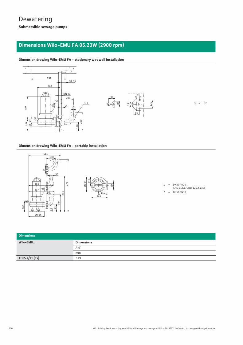
210 Wilo Building Services catalogue – 50 Hz – Drainage and sewage – Edition 2011/2012 – Subject to change without prior notice
DewateringSubmersible sewage pumps
Dimensions Wilo-EMU FA 05.23W (2900 rpm)
Dimension drawing Wilo-EMU FA - stationary wet well installation
Dimension drawing Wilo-EMU FA - portable installation
Dimensions
Wilo-EMU... DimensionsAW
mm
T 12-2/11 (Ex) 319
G 4 3 = G255
43
33
80
61
90, 95
3
120
109DN 32
26042
162
320
18 120
80
90
625
AW
1 = DN50 PN10 ANSI B16.1, Class 125, Size 2
2 = DN50 PN10
Ø250
64
273
281
407
50
12116
3
80
271
150
2
511
128
Ø23
3
265150
1389
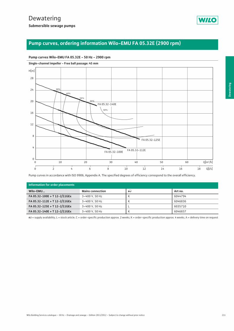
211
DewateringSubmersible sewage pumps
Dew
ater
ing
Pump curves, ordering information Wilo-EMU FA 05.32E (2900 rpm)
Wilo Building Services catalogue – 50 Hz – Drainage and sewage – Edition 2011/2012 – Subject to change without prior notice
Pump curves Wilo-EMU FA 05.32E - 50 Hz - 2900 rpm
Single-channel impeller - Free ball passage: 45 mm
Pump curves in accordance with ISO 9906, Appendix A. The specified degrees of efficiency correspond to the overall efficiency.
Information for order placements
Wilo-EMU... Mains connection � Art no.FA 05.32-100E + T 12-2/11GEx 3~400 V, 50 Hz K 6044794
FA 05.32-112E + T 12-2/11GEx 3~400 V, 50 Hz K 6046836
FA 05.32-125E + T 12-2/11GEx 3~400 V, 50 Hz L 6035710
FA 05.32-140E + T 12-2/11GEx 3~400 V, 50 Hz K 6046837
�= supply availability, L = stock article, C = order-specific production approx. 2 weeks, K = order-specific production approx. 4 weeks, A = delivery time on request
30%
40%
50%55%
58%
FA 05.32-125E
FA 05.32-112E
FA 05.32-140E
FA 05.32-100E
Q[m³/h]0 10 20 30 40 50 60
Q[l/s]0 2 4 6 8 10 12 14 16 18
H[m]
0
4
8
12
16
20
24
28
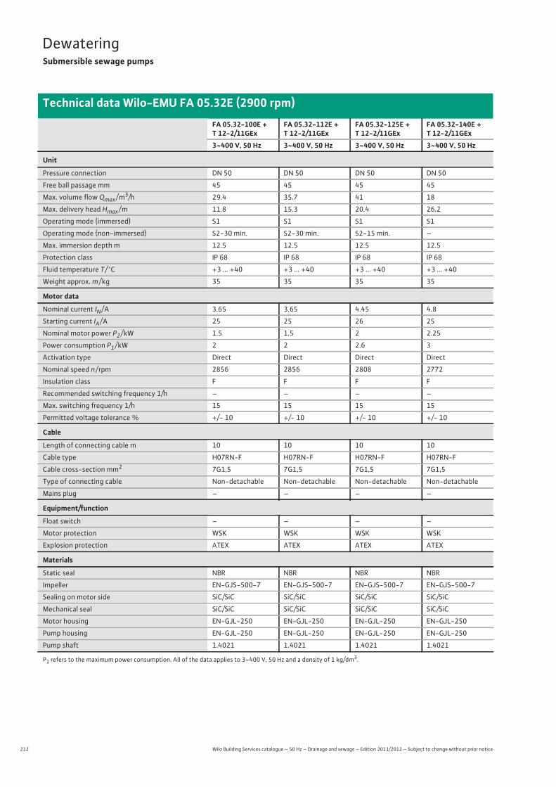
212 Wilo Building Services catalogue – 50 Hz – Drainage and sewage – Edition 2011/2012 – Subject to change without prior notice
DewateringSubmersible sewage pumps
Technical data Wilo-EMU FA 05.32E (2900 rpm)
FA 05.32-100E + T 12-2/11GEx
FA 05.32-112E + T 12-2/11GEx
FA 05.32-125E + T 12-2/11GEx
FA 05.32-140E + T 12-2/11GEx
3~400 V, 50 Hz 3~400 V, 50 Hz 3~400 V, 50 Hz 3~400 V, 50 Hz
Unit
Pressure connection DN 50 DN 50 DN 50 DN 50
Free ball passage mm 45 45 45 45
Max. volume flow Qmax / m3/h 29.4 35.7 41 18
Max. delivery head Hmax / m 11.8 15.3 20.4 26.2
Operating mode (immersed) S1 S1 S1 S1
Operating mode (non-immersed) S2-30 min. S2-30 min. S2-15 min. –
Max. immersion depth m 12.5 12.5 12.5 12.5
Protection class IP 68 IP 68 IP 68 IP 68
Fluid temperature T / °C +3 ... +40 +3 ... +40 +3 ... +40 +3 ... +40
Weight approx. m / kg 35 35 35 35
Motor data
Nominal current IN / A 3.65 3.65 4.45 4.8
Starting current IA / A 25 25 26 25
Nominal motor power P2 / kW 1.5 1.5 2 2.25
Power consumption P1 / kW 2 2 2.6 3
Activation type Direct Direct Direct Direct
Nominal speed n / rpm 2856 2856 2808 2772
Insulation class F F F F
Recommended switching frequency 1/h – – – –
Max. switching frequency 1/h 15 15 15 15
Permitted voltage tolerance % +/- 10 +/- 10 +/- 10 +/- 10
Cable
Length of connecting cable m 10 10 10 10
Cable type H07RN-F H07RN-F H07RN-F H07RN-F
Cable cross-section mm2 7G1,5 7G1,5 7G1,5 7G1,5
Type of connecting cable Non-detachable Non-detachable Non-detachable Non-detachable
Mains plug – – – –
Equipment/function
Float switch – – – –
Motor protection WSK WSK WSK WSK
Explosion protection ATEX ATEX ATEX ATEX
Materials
Static seal NBR NBR NBR NBR
Impeller EN-GJS-500-7 EN-GJS-500-7 EN-GJS-500-7 EN-GJS-500-7
Sealing on motor side SiC/SiC SiC/SiC SiC/SiC SiC/SiC
Mechanical seal SiC/SiC SiC/SiC SiC/SiC SiC/SiC
Motor housing EN-GJL-250 EN-GJL-250 EN-GJL-250 EN-GJL-250
Pump housing EN-GJL-250 EN-GJL-250 EN-GJL-250 EN-GJL-250
Pump shaft 1.4021 1.4021 1.4021 1.4021
P1 refers to the maximum power consumption. All of the data applies to 3~400 V, 50 Hz and a density of 1 kg/dm3.
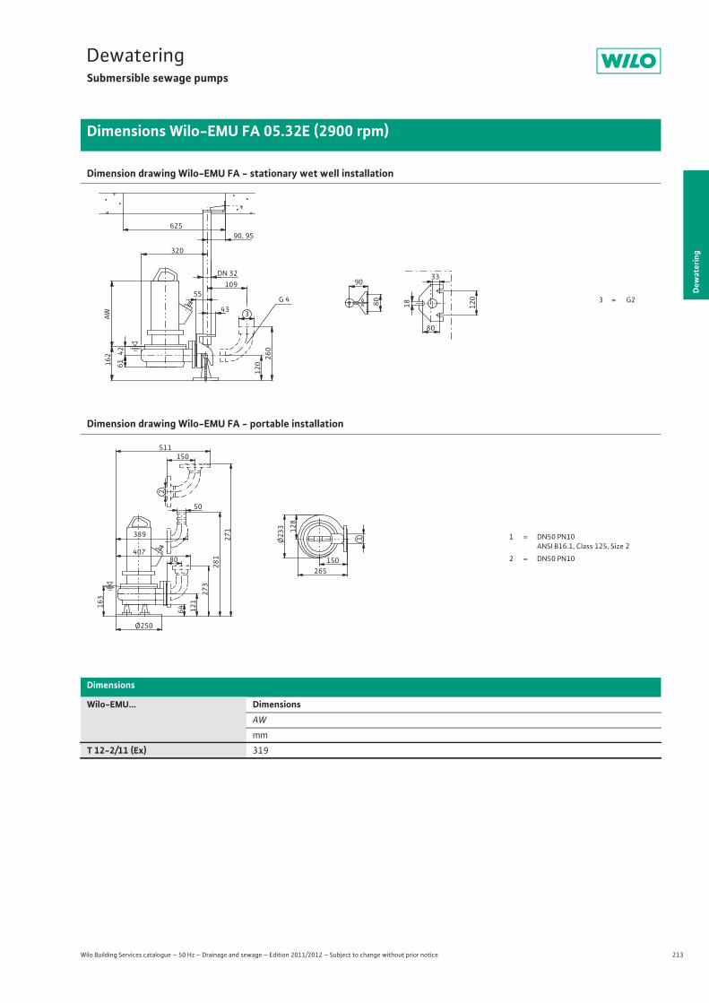
213
DewateringSubmersible sewage pumps
Dew
ater
ing
Dimensions Wilo-EMU FA 05.32E (2900 rpm)
Wilo Building Services catalogue – 50 Hz – Drainage and sewage – Edition 2011/2012 – Subject to change without prior notice
Dimension drawing Wilo-EMU FA - stationary wet well installation
Dimension drawing Wilo-EMU FA - portable installation
Dimensions
Wilo-EMU... DimensionsAW
mm
T 12-2/11 (Ex) 319
G 4 3 = G255
43
33
80
61
90, 95
3
120
109DN 32
26042
162
320
18 120
80
90
625
AW
1 = DN50 PN10 ANSI B16.1, Class 125, Size 2
2 = DN50 PN10
Ø250
64
273
281
407
50
12116
3
80
271
150
2
511
128
Ø23
3
265150
1389
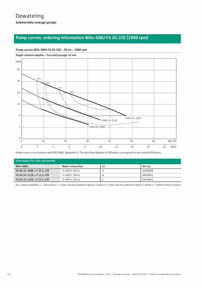
214 Wilo Building Services catalogue – 50 Hz – Drainage and sewage – Edition 2011/2012 – Subject to change without prior notice
DewateringSubmersible sewage pumps
Pump curves, ordering information Wilo-EMU FA 05.33E (2900 rpm)
Pump curves Wilo-EMU FA 05.33E - 50 Hz - 2900 rpm
Single-channel impeller - Free ball passage: 45 mm
Pump curves in accordance with ISO 9906, Appendix A. The specified degrees of efficiency correspond to the overall efficiency.
Information for order placements
Wilo-EMU... Mains connection � Art no.FA 05.33-100E + F 13.2-2/9 3~400 V, 50 Hz A 6046840
FA 05.33-112E + F 13.2-2/9 3~400 V, 50 Hz A 6046841
FA 05.33-125E + F 13.2-2/9 3~400 V, 50 Hz L 6046842
�= supply availability, L = stock article, C = order-specific production approx. 2 weeks, K = order-specific production approx. 4 weeks, A = delivery time on request
30%
40%
50%
55%
FA05.33-112E
FA05.33-100E
FA05.33-125E
Q[m³/h]0 10 20 30 40 50 60
Q[l/s]0 2 4 6 8 10 12 14 16 18
H[m]
0
4
8
12
16
20
24

215
DewateringSubmersible sewage pumps
Wilo Building Services catalogue – 50 Hz – Drainage and sewage – Edition 2011/2012 – Subject to change without prior notice
Technical data Wilo-EMU FA 05.33E (2900 rpm)
Dew
ater
ing
FA 05.33-100E + F 13.2-2/9 FA 05.33-112E + F 13.2-2/9 FA 05.33-125E + F 13.2-2/93~400 V, 50 Hz 3~400 V, 50 Hz 3~400 V, 50 Hz
Unit
Pressure connection G 2½ G 2½ G 2½
Free ball passage mm 45 45 45
Max. volume flow Qmax / m3/h 30.3 35.4 47.2
Max. delivery head Hmax / m 13.6 17.7 22.6
Operating mode (immersed) S1 S1 S1
Operating mode (non-immersed) S1 S1 S1
Max. immersion depth m 12.5 12.5 12.5
Protection class IP 68 IP 68 IP 68
Fluid temperature T / °C +3 ... +40 +3 ... +40 +3 ... +40
Weight approx. m / kg 44 44 44
Motor data
Nominal current IN / A 4.65 4.65 4.65
Starting current IA / A 24 24 24
Nominal motor power P2 / kW 2.2 2.2 2.2
Power consumption P1 / kW 2.8 2.8 2.8
Activation type Direct Direct Direct
Nominal speed n / rpm 2820 2820 2820
Insulation class F F F
Recommended switching frequency 1/h – – –
Max. switching frequency 1/h 15 15 15
Permitted voltage tolerance % +/- 10 +/- 10 +/- 10
Cable
Length of connecting cable m 10 10 10
Cable type H07RN-F H07RN-F H07RN-F
Cable cross-section mm2 4G1,5 4G1,5 4G1,5
Type of connecting cable Non-detachable Non-detachable Non-detachable
Mains plug – – –
Equipment/function
Float switch – – –
Motor protection – – –
Explosion protection – – –
Materials
Static seal NBR NBR NBR
Impeller EN-GJS-500-7 EN-GJS-500-7 EN-GJS-500-7
Sealing on motor side Carbon/ceramic Carbon/ceramic Carbon/ceramic
Mechanical seal SiC/SiC SiC/SiC SiC/SiC
Motor housing EN-GJL-250 EN-GJL-250 EN-GJL-250
Pump housing EN-GJL-250 EN-GJL-250 EN-GJL-250
Pump shaft 1.4021 1.4021 1.4021
P1 refers to the maximum power consumption. All of the data applies to 3~400 V, 50 Hz and a density of 1 kg/dm3.
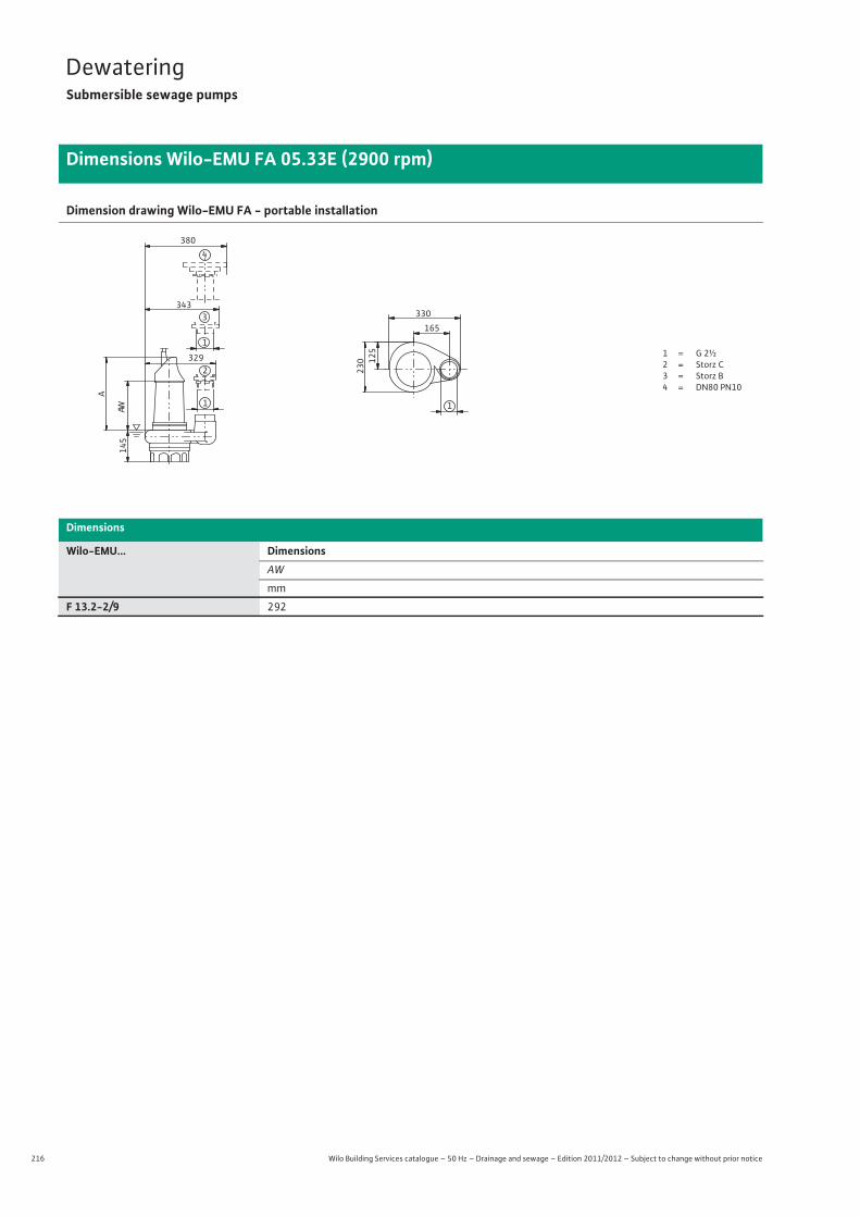
216 Wilo Building Services catalogue – 50 Hz – Drainage and sewage – Edition 2011/2012 – Subject to change without prior notice
DewateringSubmersible sewage pumps
Dimensions Wilo-EMU FA 05.33E (2900 rpm)
Dimension drawing Wilo-EMU FA - portable installation
Dimensions
Wilo-EMU... DimensionsAW
mm
F 13.2-2/9 292
1 = G 2½2 = Storz C3 = Storz B4 = DN80 PN10
145
380
343
1
329
A
AW
165
330
125
230
1
4
1
3
2
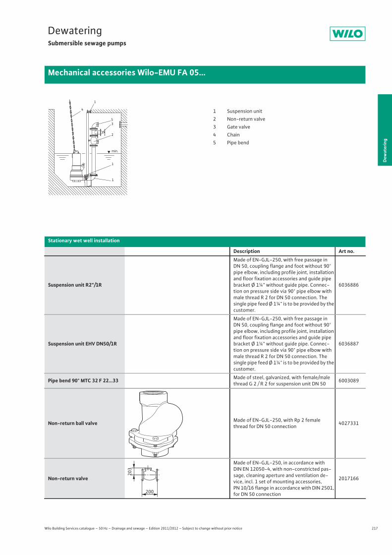
217
DewateringSubmersible sewage pumps
Dew
ater
ing
Mechanical accessories Wilo-EMU FA 05...
Wilo Building Services catalogue – 50 Hz – Drainage and sewage – Edition 2011/2012 – Subject to change without prior notice
Stationary wet well installation
Description Art no.
Suspension unit R2"/1R
Made of EN-GJL-250, with free passage in DN 50, coupling flange and foot without 90° pipe elbow, including profile joint, installation and floor fixation accessories and guide pipe bracket Ø 1¼" without guide pipe. Connec-tion on pressure side via 90° pipe elbow with male thread R 2 for DN 50 connection. The single pipe feed Ø 1¼" is to be provided by the customer.
6036886
Suspension unit EHV DN50/1R
Made of EN-GJL-250, with free passage in DN 50, coupling flange and foot without 90° pipe elbow, including profile joint, installation and floor fixation accessories and guide pipe bracket Ø 1¼" without guide pipe. Connec-tion on pressure side via 90° pipe elbow with male thread R 2 for DN 50 connection. The single pipe feed Ø 1¼" is to be provided by the customer.
6036887
Pipe bend 90° MTC 32 F 22...33 Made of steel, galvanized, with female/male thread G 2 / R 2 for suspension unit DN 50 6003089
Non-return ball valve Made of EN-GJL-250, with Rp 2 female thread for DN 50 connection 4027331
Non-return valve
Made of EN-GJL-250, in accordance with DIN EN 12050-4, with non-constricted pas-sage, cleaning aperture and ventilation de-vice, incl. 1 set of mounting accessories, PN 10/16 flange in accordance with DIN 2501, for DN 50 connection
2017166
1
4
53
2
1
1
min.
1 Suspension unit2 Non-return valve3 Gate valve4 Chain5 Pipe bend
203
200
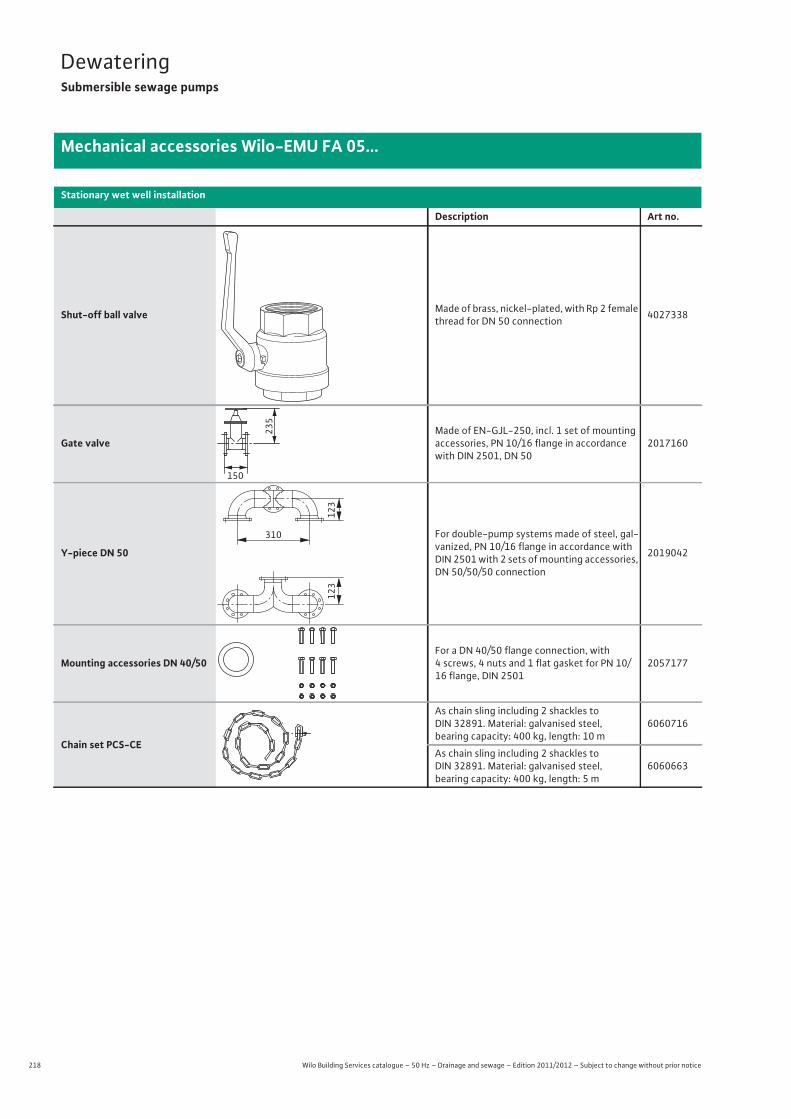
218 Wilo Building Services catalogue – 50 Hz – Drainage and sewage – Edition 2011/2012 – Subject to change without prior notice
DewateringSubmersible sewage pumps
Mechanical accessories Wilo-EMU FA 05...
Shut-off ball valve Made of brass, nickel-plated, with Rp 2 female thread for DN 50 connection 4027338
Gate valveMade of EN-GJL-250, incl. 1 set of mounting accessories, PN 10/16 flange in accordance with DIN 2501, DN 50
2017160
Y-piece DN 50
For double-pump systems made of steel, gal-vanized, PN 10/16 flange in accordance with DIN 2501 with 2 sets of mounting accessories, DN 50/50/50 connection
2019042
Mounting accessories DN 40/50For a DN 40/50 flange connection, with 4 screws, 4 nuts and 1 flat gasket for PN 10/16 flange, DIN 2501
2057177
Chain set PCS-CE
As chain sling including 2 shackles to DIN 32891. Material: galvanised steel, bearing capacity: 400 kg, length: 10 m
6060716
As chain sling including 2 shackles to DIN 32891. Material: galvanised steel, bearing capacity: 400 kg, length: 5 m
6060663
Stationary wet well installation
Description Art no.
150
235
123
123
310
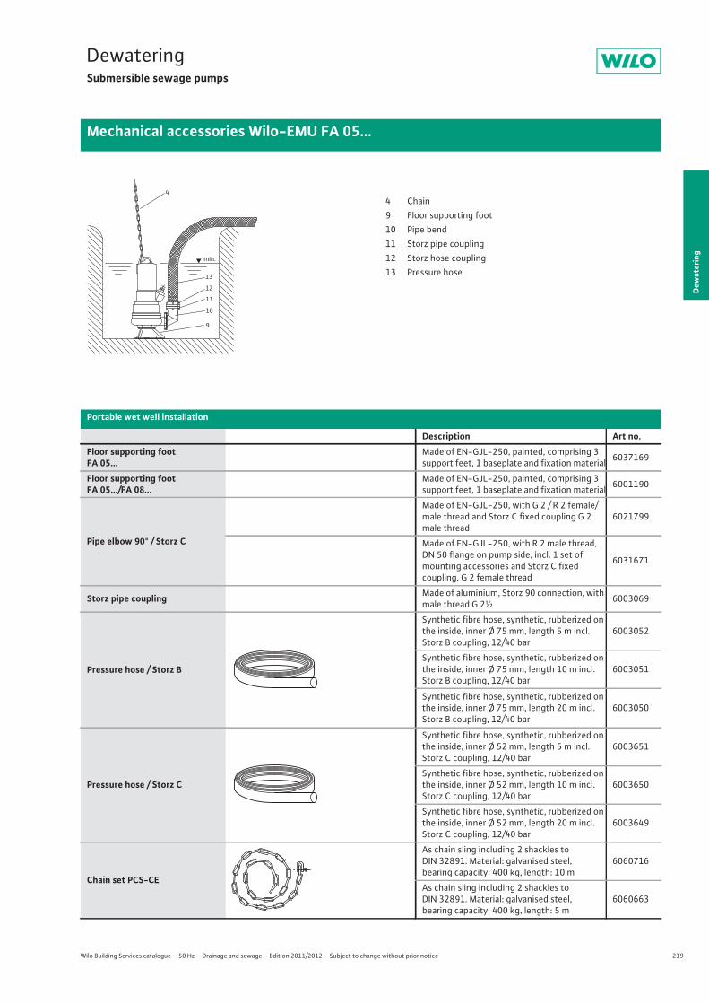
219
DewateringSubmersible sewage pumps
Dew
ater
ing
Mechanical accessories Wilo-EMU FA 05...
Wilo Building Services catalogue – 50 Hz – Drainage and sewage – Edition 2011/2012 – Subject to change without prior notice
13
12
11
10
9
min.
44 Chain9 Floor supporting foot10 Pipe bend11 Storz pipe coupling12 Storz hose coupling13 Pressure hose
Portable wet well installation
Description Art no.Floor supporting footFA 05...
Made of EN-GJL-250, painted, comprising 3 support feet, 1 baseplate and fixation material 6037169
Floor supporting footFA 05.../FA 08...
Made of EN-GJL-250, painted, comprising 3 support feet, 1 baseplate and fixation material 6001190
Pipe elbow 90° / Storz C
Made of EN-GJL-250, with G 2 / R 2 female/male thread and Storz C fixed coupling G 2 male thread
6021799
Made of EN-GJL-250, with R 2 male thread, DN 50 flange on pump side, incl. 1 set of mounting accessories and Storz C fixedcoupling, G 2 female thread
6031671
Storz pipe coupling Made of aluminium, Storz 90 connection, with male thread G 2½ 6003069
Pressure hose / Storz B
Synthetic fibre hose, synthetic, rubberized on the inside, inner Ø 75 mm, length 5 m incl. Storz B coupling, 12/40 bar
6003052
Synthetic fibre hose, synthetic, rubberized on the inside, inner Ø 75 mm, length 10 m incl. Storz B coupling, 12/40 bar
6003051
Synthetic fibre hose, synthetic, rubberized on the inside, inner Ø 75 mm, length 20 m incl. Storz B coupling, 12/40 bar
6003050
Pressure hose / Storz C
Synthetic fibre hose, synthetic, rubberized on the inside, inner Ø 52 mm, length 5 m incl. Storz C coupling, 12/40 bar
6003651
Synthetic fibre hose, synthetic, rubberized on the inside, inner Ø 52 mm, length 10 m incl. Storz C coupling, 12/40 bar
6003650
Synthetic fibre hose, synthetic, rubberized on the inside, inner Ø 52 mm, length 20 m incl. Storz C coupling, 12/40 bar
6003649
Chain set PCS-CE
As chain sling including 2 shackles to DIN 32891. Material: galvanised steel, bearing capacity: 400 kg, length: 10 m
6060716
As chain sling including 2 shackles to DIN 32891. Material: galvanised steel, bearing capacity: 400 kg, length: 5 m
6060663
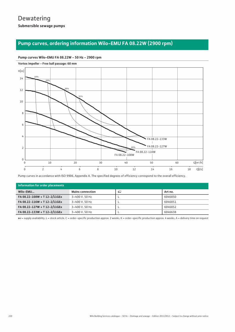
220 Wilo Building Services catalogue – 50 Hz – Drainage and sewage – Edition 2011/2012 – Subject to change without prior notice
DewateringSubmersible sewage pumps
Pump curves, ordering information Wilo-EMU FA 08.22W (2900 rpm)
Pump curves Wilo-EMU FA 08.22W - 50 Hz - 2900 rpm
Vortex impeller - Free ball passage: 60 mm
Pump curves in accordance with ISO 9906, Appendix A. The specified degrees of efficiency correspond to the overall efficiency.
Information for order placements
Wilo-EMU... Mains connection � Art no.FA 08.22-108W + T 12-2/11GEx 3~400 V, 50 Hz L 6046850
FA 08.22-116W + T 12-2/11GEx 3~400 V, 50 Hz L 6046851
FA 08.22-127W + T 12-2/11GEx 3~400 V, 50 Hz L 6046852
FA 08.22-133W + T 12-2/11GEx 3~400 V, 50 Hz L 6046638
�= supply availability, L = stock article, C = order-specific production approx. 2 weeks, K = order-specific production approx. 4 weeks, A = delivery time on request
10%
20%
20%
30%
35%
FA 08.22-127W
FA 08.22-116W
FA 08.22-133W
FA 08.22-108W
Q[m³/h]0 10 20 30 40 50 60
Q[l/s]0 2 4 6 8 10 12 14 16 18
H[m]
0
2
4
6
8
10
12
14

221
DewateringSubmersible sewage pumps
Wilo Building Services catalogue – 50 Hz – Drainage and sewage – Edition 2011/2012 – Subject to change without prior notice
Technical data Wilo-EMU FA 08.22W (2900 rpm)
Dew
ater
ing
FA 08.22-108W + T 12-2/11GEx
FA 08.22-116W + T 12-2/11GEx
FA 08.22-127W + T 12-2/11GEx
FA 08.22-133W + T 12-2/11GEx
3~400 V, 50 Hz 3~400 V, 50 Hz 3~400 V, 50 Hz 3~400 V, 50 Hz
Unit
Pressure connection DN 80 DN 80 DN 80 DN 80
Free ball passage mm 60 60 60 60
Max. volume flow Qmax / m3/h 45 47.5 54.4 58.3
Max. delivery head Hmax / m 6.7 8.5 12 14.4
Operating mode (immersed) S1 S1 S1 S1
Operating mode (non-immersed) S2-30 min. S2-30 min. S2-30 min. S2-15 min.
Max. immersion depth m 12.5 12.5 12.5 12.5
Protection class IP 68 IP 68 IP 68 IP 68
Fluid temperature T / °C +3 ... +40 +3 ... +40 +3 ... +40 +3 ... +40
Weight approx. m / kg 34 34 34 34
Motor data
Nominal current IN / A 3.65 3.65 3.65 4.45
Starting current IA / A 25 25 25 26
Nominal motor power P2 / kW 1.5 1.5 1.5 2
Power consumption P1 / kW 2 2 2 2.6
Activation type Direct Direct Direct Direct
Nominal speed n / rpm 2856 2856 2856 2808
Insulation class F F F F
Recommended switching frequency 1/h – – – –
Max. switching frequency 1/h 15 15 15 15
Permitted voltage tolerance % +/- 10 +/- 10 +/- 10 +/- 10
Cable
Length of connecting cable m 10 10 10 10
Cable type H07RN-F H07RN-F H07RN-F H07RN-F
Cable cross-section mm2 7G1,5 7G1,5 7G1,5 7G1,5
Type of connecting cable Non-detachable Non-detachable Non-detachable Non-detachable
Mains plug – – – –
Equipment/function
Float switch – – – –
Motor protection WSK WSK WSK WSK
Explosion protection ATEX ATEX ATEX ATEX
Materials
Static seal NBR NBR NBR NBR
Impeller EN-GJL-250 EN-GJL-250 EN-GJL-250 EN-GJL-250
Sealing on motor side SiC/SiC SiC/SiC SiC/SiC SiC/SiC
Mechanical seal SiC/SiC SiC/SiC SiC/SiC SiC/SiC
Motor housing EN-GJL-250 EN-GJL-250 EN-GJL-250 EN-GJL-250
Pump housing EN-GJL-250 EN-GJL-250 EN-GJL-250 EN-GJL-250
Pump shaft 1.4021 1.4021 1.4021 1.4021
P1 refers to the maximum power consumption. All of the data applies to 3~400 V, 50 Hz and a density of 1 kg/dm3.
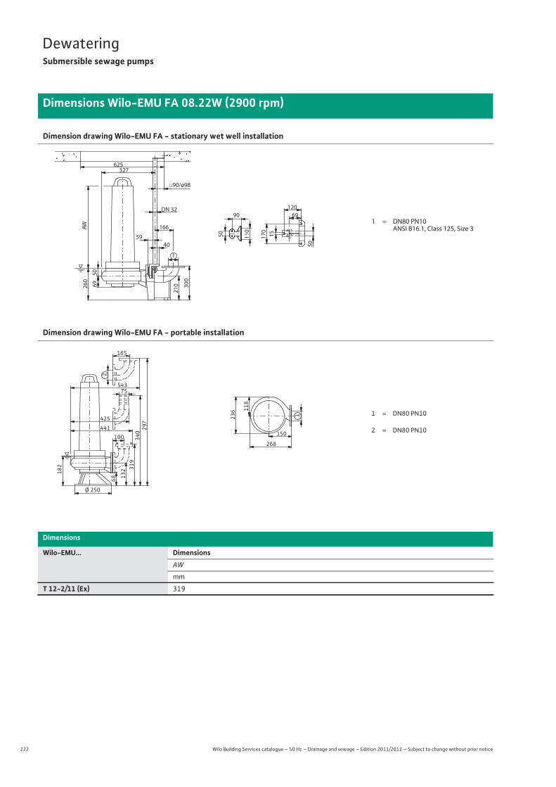
222 Wilo Building Services catalogue – 50 Hz – Drainage and sewage – Edition 2011/2012 – Subject to change without prior notice
DewateringSubmersible sewage pumps
Dimensions Wilo-EMU FA 08.22W (2900 rpm)
Dimension drawing Wilo-EMU FA - stationary wet well installation
Dimension drawing Wilo-EMU FA - portable installation
Dimensions
Wilo-EMU... DimensionsAW
mm
T 12-2/11 (Ex) 319
50
327
69 300
59
1
210
□90/ø98
166
15170
120DN 326990
260
50
50
40
625
110AW
1 = DN80 PN10ANSI B16.1, Class 125, Size 3
1
150
268
236 11
8
Ø 250
68 132 31
9340
100441
75
182
297
543
165
2
4251 = DN80 PN10
2 = DN80 PN10
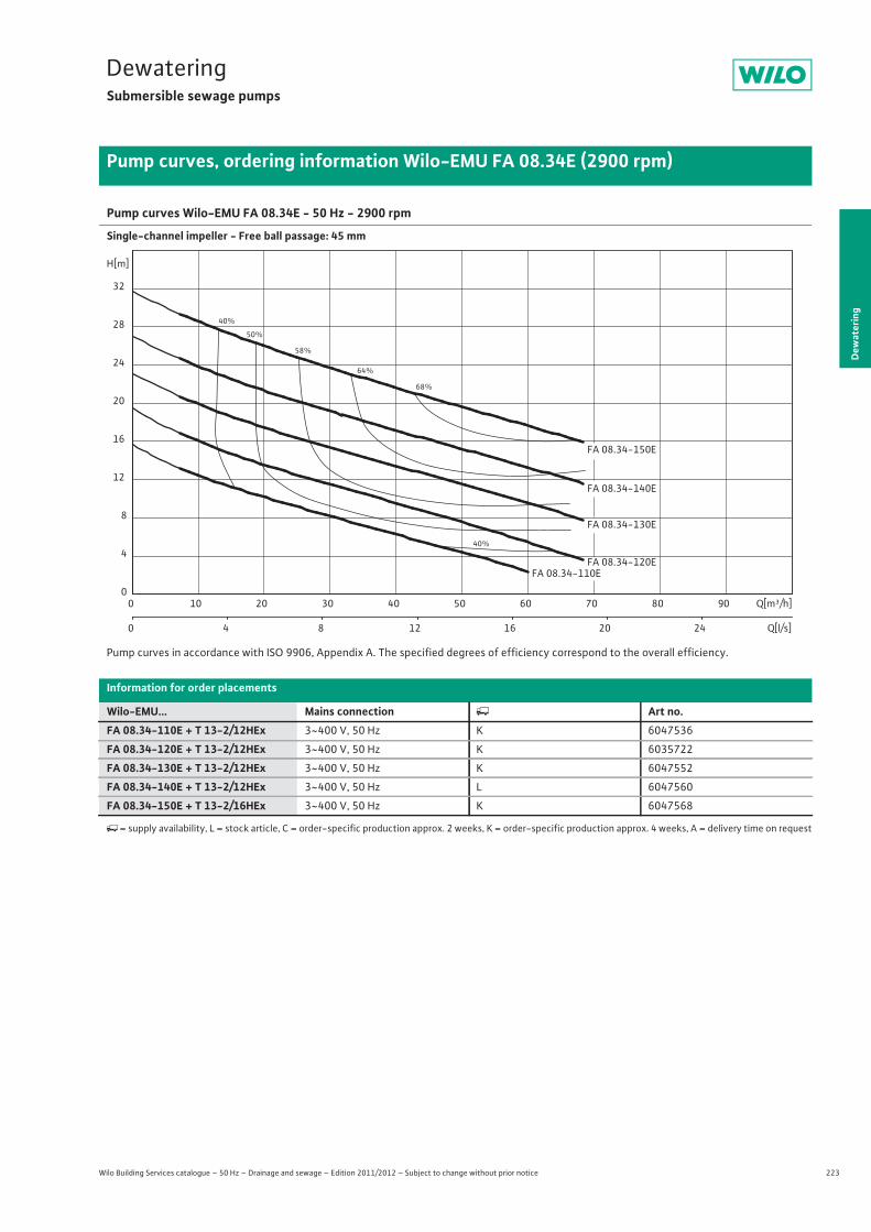
223
DewateringSubmersible sewage pumps
Dew
ater
ing
Pump curves, ordering information Wilo-EMU FA 08.34E (2900 rpm)
Wilo Building Services catalogue – 50 Hz – Drainage and sewage – Edition 2011/2012 – Subject to change without prior notice
Pump curves Wilo-EMU FA 08.34E - 50 Hz - 2900 rpm
Single-channel impeller - Free ball passage: 45 mm
Pump curves in accordance with ISO 9906, Appendix A. The specified degrees of efficiency correspond to the overall efficiency.
Information for order placements
Wilo-EMU... Mains connection � Art no.FA 08.34-110E + T 13-2/12HEx 3~400 V, 50 Hz K 6047536
FA 08.34-120E + T 13-2/12HEx 3~400 V, 50 Hz K 6035722
FA 08.34-130E + T 13-2/12HEx 3~400 V, 50 Hz K 6047552
FA 08.34-140E + T 13-2/12HEx 3~400 V, 50 Hz L 6047560
FA 08.34-150E + T 13-2/16HEx 3~400 V, 50 Hz K 6047568
�= supply availability, L = stock article, C = order-specific production approx. 2 weeks, K = order-specific production approx. 4 weeks, A = delivery time on request
40%
40%
50%
58%
64%
68%
FA 08.34-130E
FA 08.34-110EFA 08.34-120E
FA 08.34-140E
FA 08.34-150E
Q[m³/h]0 10 20 30 40 50 60 70 80 90
Q[l/s]0 4 8 12 16 20 24
H[m]
0
4
8
12
16
20
24
28
32

224 Wilo Building Services catalogue – 50 Hz – Drainage and sewage – Edition 2011/2012 – Subject to change without prior notice
DewateringSubmersible sewage pumps
Technical data Wilo-EMU FA 08.34E (2900 rpm)
FA 08.34-110E + T 13-2/12HEx
FA 08.34-120E + T 13-2/12HEx
FA 08.34-130E + T 13-2/12HEx
FA 08.34-140E + T 13-2/12HEx
FA 08.34-150E + T 13-2/16HEx
3~400 V, 50 Hz 3~400 V, 50 Hz 3~400 V, 50 Hz 3~400 V, 50 Hz 3~400 V, 50 Hz
Unit
Pressure connection DN 80 DN 80 DN 80 DN 80 DN 80
Free ball passage mm 45 45 45 45 45
Max. volume flow Qmax / m3/h 60.1 71.3 83.2 87.8 87.8
Max. delivery head Hmax / m 15.6 19.4 23 27 31.7
Operating mode (immersed) S1 S1 S1 S1 S1
Operating mode (non-immersed) S1 S1 S2-15 min. S2-15 min. S2-15 min.
Max. immersion depth m 12.5 12.5 12.5 12.5 12.5
Protection class IP 68 IP 68 IP 68 IP 68 IP 68
Fluid temperature T / °C +3 ... +40 +3 ... +40 +3 ... +40 +3 ... +40 +3 ... +40
Weight approx. m / kg 54.5 54.5 55 55 58.5
Motor data
Nominal current IN / A 5 5 7.6 7.6 7.6
Starting current IA / A 37 37 37 37 37
Nominal motor power P2 / kW 2.2 2.2 3.75 3.75 5
Power consumption P1 / kW 2.8 2.8 4.7 4.7 6
Activation type Direct Direct Direct Direct Direct
Nominal speed n / rpm 2890 2890 2825 2825 2825
Insulation class F F F F F
Recommended switching frequency 1/h – – – – –
Max. switching frequency 1/h 15 15 15 15 15
Permitted voltage tolerance % +/- 10 +/- 10 +/- 10 +/- 10 +/- 10
Cable
Length of connecting cable m 10 10 10 10 10
Cable type H07RN-F H07RN-F H07RN-F H07RN-F H07RN-F
Cable cross-section mm2 7G1,5 7G1,5 7G1,5 7G1,5 7G1,5
Type of connecting cable Non-detachable Non-detachable Non-detachable Non-detachable Non-detachable
Mains plug – – – – –
Equipment/function
Float switch – – – – –
Motor protection WSK WSK WSK WSK WSK
Explosion protection ATEX ATEX ATEX ATEX ATEX
Materials
Static seal NBR NBR NBR NBR NBR
Impeller EN-GJL-250 EN-GJL-250 EN-GJL-250 EN-GJL-250 EN-GJL-250
Sealing on motor side NBR NBR NBR NBR NBR
Mechanical seal SiC/SiC SiC/SiC SiC/SiC SiC/SiC SiC/SiC
Motor housing EN-GJL-250 EN-GJL-250 EN-GJL-250 EN-GJL-250 EN-GJL-250
Pump housing EN-GJL-250 EN-GJL-250 EN-GJL-250 EN-GJL-250 EN-GJL-250
Pump shaft 1.4021 1.4021 1.4021 1.4021 1.4021
P1 refers to the maximum power consumption. All of the data applies to 3~400 V, 50 Hz and a density of 1 kg/dm3.

225
DewateringSubmersible sewage pumps
Dew
ater
ing
Dimensions Wilo-EMU FA 08.34E (2900 rpm)
Wilo Building Services catalogue – 50 Hz – Drainage and sewage – Edition 2011/2012 – Subject to change without prior notice
Dimension drawing Wilo-EMU FA - stationary wet well installation
Dimension drawing Wilo-EMU FA - portable installation
Dimensions
Wilo-EMU... DimensionsAW
mm
T 13-2/12 (Ex) 319
T 13-2/16 (Ex) 374
39
324
77 300
59
1
210
90/98
166
15
170
120 DN 32 69 90
249
50 50
40
625
110 A W
1 = DN80 PN10 ANSI B16.1, Class 125, Size 3
1
150
265
230 12
5
Ø 250
64
141 32
8351
100 431
75
180
306
468
165
2
4151 = DN80 PN10
ANSI B16.1, Class 125, Size 32 = DN80 PN10
3
= DN65 PN10
ANSI B16.1, Class 125, Size 2,53
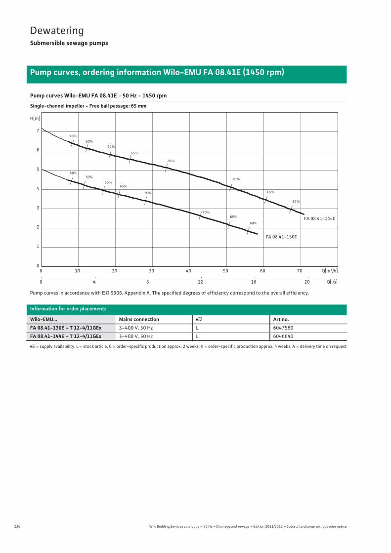
226 Wilo Building Services catalogue – 50 Hz – Drainage and sewage – Edition 2011/2012 – Subject to change without prior notice
DewateringSubmersible sewage pumps
Pump curves, ordering information Wilo-EMU FA 08.41E (1450 rpm)
Pump curves Wilo-EMU FA 08.41E - 50 Hz - 1450 rpm
Single-channel impeller - Free ball passage: 65 mm
Pump curves in accordance with ISO 9906, Appendix A. The specified degrees of efficiency correspond to the overall efficiency.
Information for order placements
Wilo-EMU... Mains connection � Art no.FA 08.41-130E + T 12-4/11GEx 3~400 V, 50 Hz L 6047580
FA 08.41-144E + T 12-4/11GEx 3~400 V, 50 Hz L 6046640
�= supply availability, L = stock article, C = order-specific production approx. 2 weeks, K = order-specific production approx. 4 weeks, A = delivery time on request
40%
40%
50%
50%
60%
60%
60%
60%
65%
65%
65%
65%
70%
70%
70%
70%
FA 08.41-144E
FA 08.41-130E
Q[m³/h]0 10 20 30 40 50 60 70
Q[l/s]0 4 8 12 16 20
H[m]
0
1
2
3
4
5
6
7

227
DewateringSubmersible sewage pumps
Wilo Building Services catalogue – 50 Hz – Drainage and sewage – Edition 2011/2012 – Subject to change without prior notice
Technical data Wilo-EMU FA 08.41E (1450 rpm)
Dew
ater
ing
FA 08.41-130E + T 12-4/11GEx FA 08.41-144E + T 12-4/11GEx3~400 V, 50 Hz 3~400 V, 50 Hz
Unit
Pressure connection DN 80 DN 80
Free ball passage mm 65 65
Max. volume flow Qmax / m3/h 58.3 70.9
Max. delivery head Hmax / m 5 7
Operating mode (immersed) S1 S1
Operating mode (non-immersed) S1 S2-15 min.
Max. immersion depth m 12.5 12.5
Protection class IP 68 IP 68
Fluid temperature T / °C +3 ... +40 +3 ... +40
Weight approx. m / kg 38 38
Motor data
Nominal current IN / A 2.5 3.3
Starting current IA / A 16 16
Nominal motor power P2 / kW 0.5 1.3
Power consumption P1 / kW 0.8 1.8
Activation type Direct Direct
Nominal speed n / rpm 1460 1392
Insulation class F F
Recommended switching frequency 1/h – –
Max. switching frequency 1/h 15 15
Permitted voltage tolerance % +/- 10 +/- 10
Cable
Length of connecting cable m 10 10
Cable type H07RN-F H07RN-F
Cable cross-section mm2 7G1,5 7G1,5
Type of connecting cable Non-detachable Non-detachable
Mains plug – –
Equipment/function
Float switch – –
Motor protection WSK WSK
Explosion protection ATEX ATEX
Materials
Static seal NBR NBR
Impeller EN-GJS-500-7 EN-GJS-500-7
Sealing on motor side SiC/SiC SiC/SiC
Mechanical seal SiC/SiC SiC/SiC
Motor housing EN-GJL-250 EN-GJL-250
Pump housing EN-GJL-250 EN-GJL-250
Pump shaft 1.4021 1.4021
P1 refers to the maximum power consumption. All of the data applies to 3~400 V, 50 Hz and a density of 1 kg/dm3.

228 Wilo Building Services catalogue – 50 Hz – Drainage and sewage – Edition 2011/2012 – Subject to change without prior notice
DewateringSubmersible sewage pumps
Dimensions Wilo-EMU FA 08.41E (1450 rpm)
Dimension drawing Wilo-EMU FA - stationary wet well installation
Dimension drawing Wilo-EMU FA - portable installation
Dimensions, weights
Wilo-EMU... DimensionsAW
mm
T 12-4/11 (Ex) 319
53
329
76 300
59
1
210
90/98
166
15170
120DN 326990
263
50
50
40
625
110AW
1 = DN80 PN10ANSI B16.1, Class 125, Size 3
1
150
270
239 12
6
Ø 250
68 141 32
8351
100441
75
194
306
543
165
2
4251 = DN80 PN10
2 = DN80 PN10
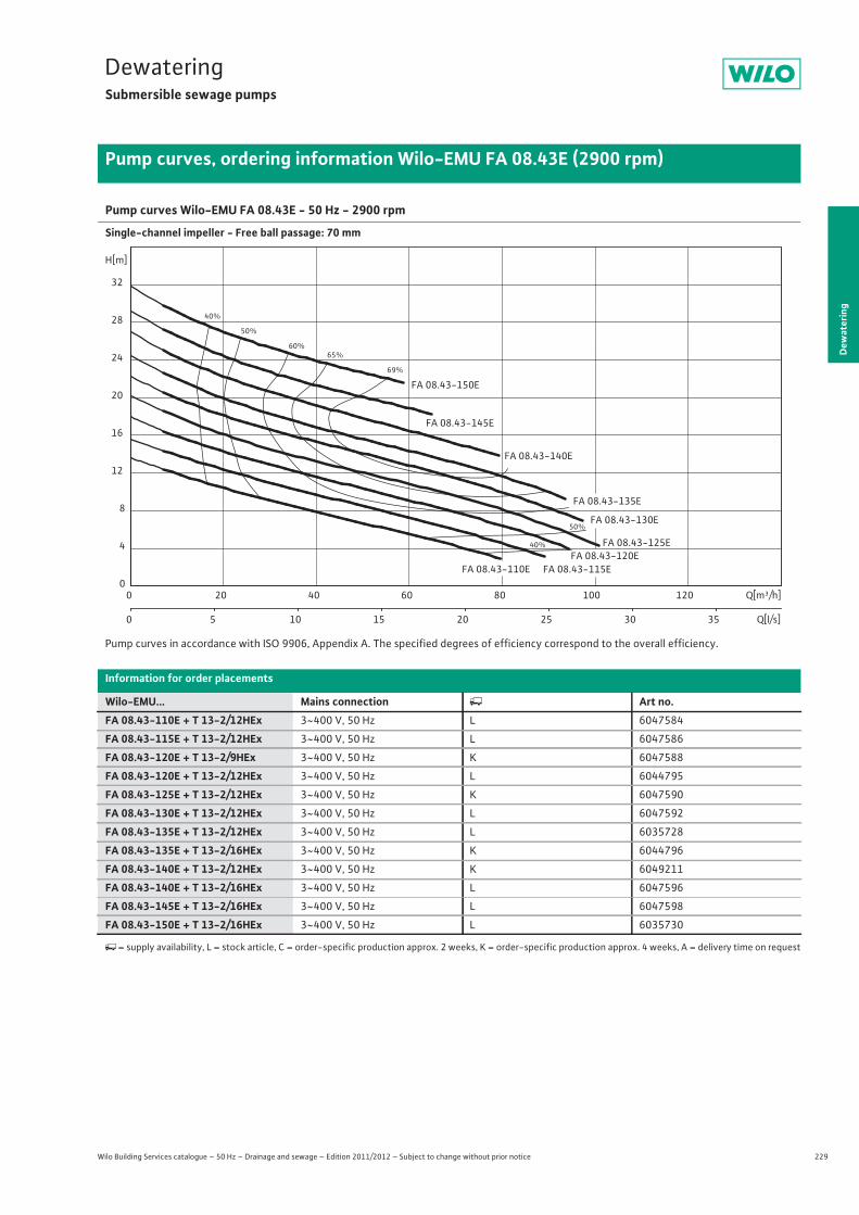
229
DewateringSubmersible sewage pumps
Dew
ater
ing
Pump curves, ordering information Wilo-EMU FA 08.43E (2900 rpm)
Wilo Building Services catalogue – 50 Hz – Drainage and sewage – Edition 2011/2012 – Subject to change without prior notice
Pump curves Wilo-EMU FA 08.43E - 50 Hz - 2900 rpm
Single-channel impeller - Free ball passage: 70 mm
Pump curves in accordance with ISO 9906, Appendix A. The specified degrees of efficiency correspond to the overall efficiency.
Information for order placements
Wilo-EMU... Mains connection � Art no.FA 08.43-110E + T 13-2/12HEx 3~400 V, 50 Hz L 6047584
FA 08.43-115E + T 13-2/12HEx 3~400 V, 50 Hz L 6047586
FA 08.43-120E + T 13-2/9HEx 3~400 V, 50 Hz K 6047588
FA 08.43-120E + T 13-2/12HEx 3~400 V, 50 Hz L 6044795
FA 08.43-125E + T 13-2/12HEx 3~400 V, 50 Hz K 6047590
FA 08.43-130E + T 13-2/12HEx 3~400 V, 50 Hz L 6047592
FA 08.43-135E + T 13-2/12HEx 3~400 V, 50 Hz L 6035728
FA 08.43-135E + T 13-2/16HEx 3~400 V, 50 Hz K 6044796
FA 08.43-140E + T 13-2/12HEx 3~400 V, 50 Hz K 6049211
FA 08.43-140E + T 13-2/16HEx 3~400 V, 50 Hz L 6047596
FA 08.43-145E + T 13-2/16HEx 3~400 V, 50 Hz L 6047598
FA 08.43-150E + T 13-2/16HEx 3~400 V, 50 Hz L 6035730
�= supply availability, L = stock article, C = order-specific production approx. 2 weeks, K = order-specific production approx. 4 weeks, A = delivery time on request
40%
40%
50%
50%
60%65%
69%
FA 08.43-140E
FA 08.43-135E
FA 08.43-110E
FA 08.43-130E
FA 08.43-120E
FA 08.43-145E
FA 08.43-150E
FA 08.43-115E
FA 08.43-125E
Q[m³/h]0 20 40 60 80 100 120
Q[l/s]0 5 10 15 20 25 30 35
H[m]
0
4
8
12
16
20
24
28
32
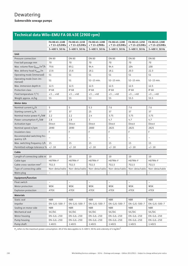
230 Wilo Building Services catalogue – 50 Hz – Drainage and sewage – Edition 2011/2012 – Subject to change without prior notice
DewateringSubmersible sewage pumps
Technical data Wilo-EMU FA 08.43E (2900 rpm)
FA 08.43-110E + T 13-2/12HEx
FA 08.43-115E + T 13-2/12HEx
FA 08.43-120E + T 13-2/9HEx
FA 08.43-120E + T 13-2/12HEx
FA 08.43-125E + T 13-2/12HEx
FA 08.43-130E + T 13-2/12HEx
3~400 V, 50 Hz 3~400 V, 50 Hz 3~400 V, 50 Hz 3~400 V, 50 Hz 3~400 V, 50 Hz 3~400 V, 50 Hz
Unit
Pressure connection DN 80 DN 80 DN 80 DN 80 DN 80 DN 80
Free ball passage mm 70 70 70 70 70 70
Max. volume flow Qmax / m3/h 79.6 89.1 94.4 94.4 104 108
Max. delivery head Hmax / m 13.6 15.6 18.1 18.1 20.3 22.3
Operating mode (immersed) S1 S1 S1 S1 S1 S1
Operating mode (non-im-mersed) S1 S1 S2-15 min. S2-15 min. S2-15 min. S2-15 min.
Max. immersion depth m 12.5 12.5 12.5 12.5 12.5 12.5
Protection class IP 68 IP 68 IP 68 IP 68 IP 68 IP 68
Fluid temperature T / °C +3 ... +40 +3 ... +40 +3 ... +40 +3 ... +40 +3 ... +40 +3 ... +40
Weight approx. m / kg 55 55 53 55 55.5 55.5
Motor data
Nominal current IN / A 5 5 5.3 7.6 7.6 7.6
Starting current IA / A 37 37 25 37 37 37
Nominal motor power P2 / kW 2.2 2.2 2.4 3.75 3.75 3.75
Power consumption P1 / kW 2.8 2.8 3 4.7 4.7 4.7
Activation type Direct Direct Direct Direct Direct Direct
Nominal speed n / rpm 2890 2890 2800 2825 2825 2825
Insulation class F F F F F F
Recommended switching fre-quency 1/h – – – – – –
Max. switching frequency 1/h 15 15 15 15 15 15
Permitted voltage tolerance % +/- 10 +/- 10 +/- 10 +/- 10 +/- 10 +/- 10
Cable
Length of connecting cable m 10 10 10 10 10 10
Cable type H07RN-F H07RN-F H07RN-F H07RN-F H07RN-F H07RN-F
Cable cross-section mm2 7G1,5 7G1,5 7G1,5 7G1,5 7G1,5 7G1,5
Type of connecting cable Non-detachable Non-detachable Non-detachable Non-detachable Non-detachable Non-detachable
Mains plug – – – – – –
Equipment/function
Float switch – – – – – –
Motor protection WSK WSK WSK WSK WSK WSK
Explosion protection ATEX ATEX ATEX ATEX ATEX ATEX
Materials
Static seal NBR NBR NBR NBR NBR NBR
Impeller EN-GJS-500-7 EN-GJS-500-7 EN-GJS-500-7 EN-GJS-500-7 EN-GJS-500-7 EN-GJS-500-7
Sealing on motor side NBR NBR NBR NBR NBR NBR
Mechanical seal SiC/SiC SiC/SiC SiC/SiC SiC/SiC SiC/SiC SiC/SiC
Motor housing EN-GJL-250 EN-GJL-250 EN-GJL-250 EN-GJL-250 EN-GJL-250 EN-GJL-250
Pump housing EN-GJL-250 EN-GJL-250 EN-GJL-250 EN-GJL-250 EN-GJL-250 EN-GJL-250
Pump shaft 1.4021 1.4021 1.4021 1.4021 1.4021 1.4021
P1 refers to the maximum power consumption. All of the data applies to 3~400 V, 50 Hz and a density of 1 kg/dm3.
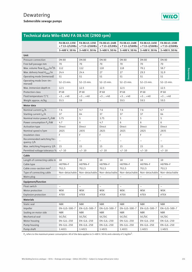
231
DewateringSubmersible sewage pumps
Wilo Building Services catalogue – 50 Hz – Drainage and sewage – Edition 2011/2012 – Subject to change without prior notice
Technical data Wilo-EMU FA 08.43E (2900 rpm)
Dew
ater
ing
FA 08.43-135E + T 13-2/12HEx
FA 08.43-135E + T 13-2/16HEx
FA 08.43-140E + T 13-2/12HEx
FA 08.43-140E + T 13-2/16HEx
FA 08.43-145E + T 13-2/16HEx
FA 08.43-150E + T 13-2/16HEx
3~400 V, 50 Hz 3~400 V, 50 Hz 3~400 V, 50 Hz 3~400 V, 50 Hz 3~400 V, 50 Hz 3~400 V, 50 Hz
Unit
Pressure connection DN 80 DN 80 DN 80 DN 80 DN 80 DN 80
Free ball passage mm 70 70 70 70 70 70
Max. volume flow Qmax / m3/h 112 112 118 118 78.1 58.7
Max. delivery head Hmax / m 24.4 24.4 27 27 29.3 31.9
Operating mode (immersed) S1 S1 S1 S1 S1 S1
Operating mode (non-im-mersed) S2-15 min. S2-15 min. S2-15 min. S2-15 min. S2-15 min. S2-15 min.
Max. immersion depth m 12.5 12.5 12.5 12.5 12.5 12.5
Protection class IP 68 IP 68 IP 68 IP 68 IP 68 IP 68
Fluid temperature T / °C +3 ... +40 +3 ... +40 +3 ... +40 +3 ... +40 +3 ... +40 +3 ... +40
Weight approx. m / kg 55.5 59 – 59.5 59.5 59.5
Motor data
Nominal current IN / A 7.6 9.7 7.6 7.6 7.6 9.7
Starting current IA / A 37 64 37 37 37 64
Nominal motor power P2 / kW 3.75 5 3.75 5 5 5
Power consumption P1 / kW 4.7 6 4.7 6 6 6
Activation type Direct Direct Direct Direct Direct Direct
Nominal speed n / rpm 2825 2835 2825 2825 2825 2835
Insulation class F F F F F F
Recommended switching fre-quency 1/h – – – – – –
Max. switching frequency 1/h 15 15 15 15 15 15
Permitted voltage tolerance % +/- 10 +/- 10 +/- 10 +/- 10 +/- 10 +/- 10
Cable
Length of connecting cable m 10 10 10 10 10 10
Cable type H07RN-F H07RN-F H07RN-F H07RN-F H07RN-F H07RN-F
Cable cross-section mm2 7G1,5 7G1,5 7G1,5 7G1,5 7G1,5 7G1,5
Type of connecting cable Non-detachable Non-detachable Non-detachable Non-detachable Non-detachable Non-detachable
Mains plug – – – – – –
Equipment/function
Float switch – – – – – –
Motor protection WSK WSK WSK WSK WSK WSK
Explosion protection ATEX ATEX ATEX ATEX ATEX ATEX
Materials
Static seal NBR NBR NBR NBR NBR NBR
Impeller EN-GJS-500-7 EN-GJS-500-7 EN-GJS-500-7 EN-GJS-500-7 EN-GJS-500-7 EN-GJS-500-7
Sealing on motor side NBR NBR NBR NBR NBR NBR
Mechanical seal SiC/SiC SiC/SiC SiC/SiC SiC/SiC SiC/SiC SiC/SiC
Motor housing EN-GJL-250 EN-GJL-250 EN-GJL-250 EN-GJL-250 EN-GJL-250 EN-GJL-250
Pump housing EN-GJL-250 EN-GJL-250 EN-GJL-250 EN-GJL-250 EN-GJL-250 EN-GJL-250
Pump shaft 1.4021 1.4021 1.4021 1.4021 1.4021 1.4021
P1 refers to the maximum power consumption. All of the data applies to 3~400 V, 50 Hz and a density of 1 kg/dm3.

232 Wilo Building Services catalogue – 50 Hz – Drainage and sewage – Edition 2011/2012 – Subject to change without prior notice
DewateringSubmersible sewage pumps
Dimensions Wilo-EMU FA 08.43E (2900 rpm)
Dimension drawing Wilo-EMU FA - stationary wet well installation
Dimension drawing Wilo-EMU FA - portable installation
Dimensions
Wilo-EMU... DimensionsAW
mm
T 13-2/9 (Ex) 319
T 13-2/12 (Ex) 319
T 13-2/16 (Ex) 374
54
329
91 300
59
1
210
90/98
166
15170
120DN 326990
264
50
50
40
625
110AW
1 = DN80 PN10ANSI B16.1, Class 125, Size 3
1
150
269
239 12
6
Ø 250
68 155 34
2365
100441
75
213
320
534
165
2
4251 = DN80 PN10
2 = DN80 PN10
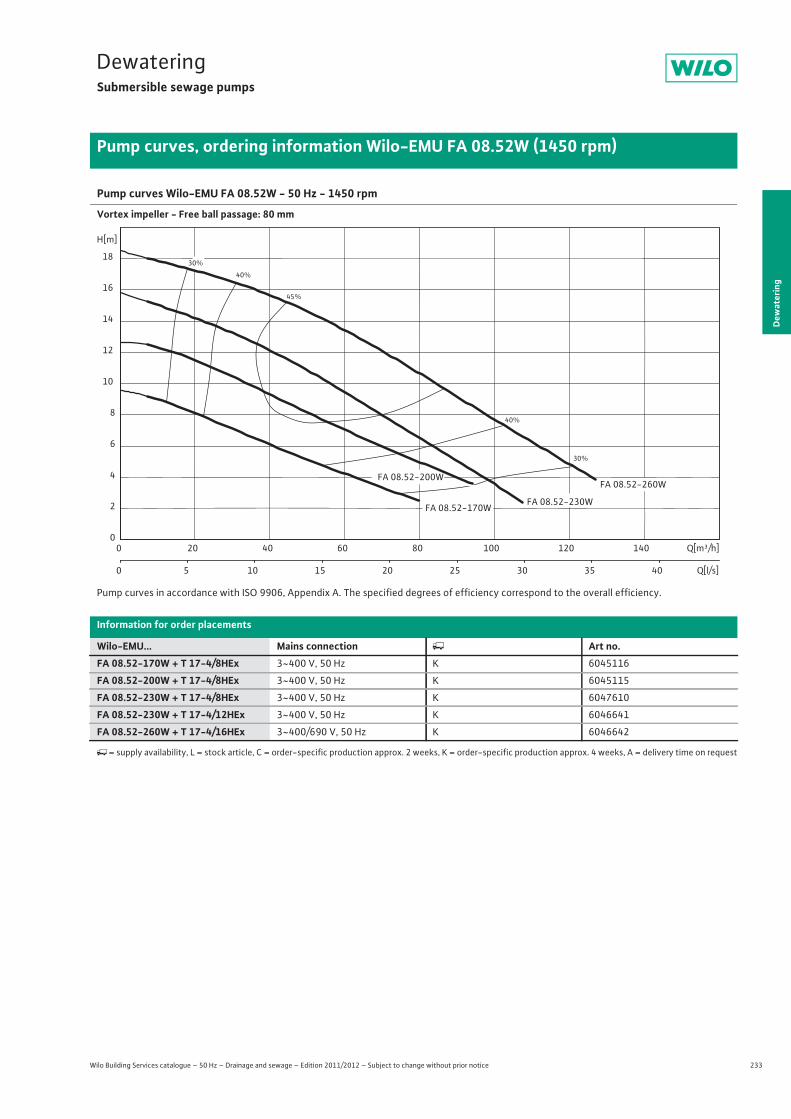
233
DewateringSubmersible sewage pumps
Dew
ater
ing
Pump curves, ordering information Wilo-EMU FA 08.52W (1450 rpm)
Wilo Building Services catalogue – 50 Hz – Drainage and sewage – Edition 2011/2012 – Subject to change without prior notice
Pump curves Wilo-EMU FA 08.52W - 50 Hz - 1450 rpm
Vortex impeller - Free ball passage: 80 mm
Pump curves in accordance with ISO 9906, Appendix A. The specified degrees of efficiency correspond to the overall efficiency.
Information for order placements
Wilo-EMU... Mains connection � Art no.FA 08.52-170W + T 17-4/8HEx 3~400 V, 50 Hz K 6045116
FA 08.52-200W + T 17-4/8HEx 3~400 V, 50 Hz K 6045115
FA 08.52-230W + T 17-4/8HEx 3~400 V, 50 Hz K 6047610
FA 08.52-230W + T 17-4/12HEx 3~400 V, 50 Hz K 6046641
FA 08.52-260W + T 17-4/16HEx 3~400/690 V, 50 Hz K 6046642
�= supply availability, L = stock article, C = order-specific production approx. 2 weeks, K = order-specific production approx. 4 weeks, A = delivery time on request
30%
30%
40%
40%
45%
FA 08.52-200W
FA 08.52-170WFA 08.52-230W
FA 08.52-260W
Q[m³/h]0 20 40 60 80 100 120 140
Q[l/s]0 5 10 15 20 25 30 35 40
H[m]
0
2
4
6
8
10
12
14
16
18

234 Wilo Building Services catalogue – 50 Hz – Drainage and sewage – Edition 2011/2012 – Subject to change without prior notice
DewateringSubmersible sewage pumps
Technical data Wilo-EMU FA 08.52W (1450 rpm)
FA 08.52-170W + T 17-4/8HEx
FA 08.52-200W + T 17-4/8HEx
FA 08.52-230W + T 17-4/8HEx
FA 08.52-230W + T 17-4/12HEx
FA 08.52-260W + T 17-4/16HEx
3~400 V, 50 Hz 3~400 V, 50 Hz 3~400 V, 50 Hz 3~400 V, 50 Hz 3~400/690 V, 50 Hz
Unit
Pressure connection DN 80 DN 80 DN 80 DN 80 DN 80
Free ball passage mm 80 80 80 80 80
Max. volume flow Qmax / m3/h 79.7 94.2 108 108 127
Max. delivery head Hmax / m 9.5 12.6 15.8 15.8 18.4
Operating mode (immersed) S1 S1 S1 S1 S1
Operating mode (non-immersed) – – – – –
Max. immersion depth m 12.5 12.5 12.5 12.5 12.5
Protection class IP 68 IP 68 IP 68 IP 68 IP 68
Fluid temperature T / °C +3 ... +40 +3 ... +40 +3 ... +40 +3 ... +40 +3 ... +40
Weight approx. m / kg 71 72 74 82 95
Motor data
Nominal current IN / A 7.9 7.9 7.9 9.4 13.5
Starting current IA / A 37 37 37 47 68
Nominal motor power P2 / kW 3.5 3.5 3.5 4.5 6.5
Power consumption P1 / kW 4.5 4.5 4.5 5.8 8.2
Activation type Direct Direct Direct Direct Star-delta
Nominal speed n / rpm 1410 1410 1410 1405 1400
Insulation class F F F F F
Recommended switching frequency 1/h – – – – –
Max. switching frequency 1/h 15 15 15 15 15
Permitted voltage tolerance % +/- 10 +/- 10 +/- 10 +/- 10 +/- 10
Cable
Length of connecting cable m 10 10 10 10 10
Cable type H07RN-F H07RN-F H07RN-F H07RN-F H07RN-F
Cable cross-section mm2 7G1,5 7G1,5 7G1,5 7G1,5 7G1,5
Type of connecting cable Non-detachable Non-detachable Non-detachable Non-detachable Non-detachable
Mains plug – – – – –
Equipment/function
Float switch – – – – –
Motor protection WSK WSK WSK WSK WSK
Explosion protection ATEX ATEX ATEX ATEX ATEX
Materials
Static seal NBR NBR NBR NBR NBR
Impeller EN-GJL-250 EN-GJL-250 EN-GJL-250 EN-GJL-250 EN-GJL-250
Sealing on motor side NBR NBR NBR NBR NBR
Mechanical seal SiC/SiC SiC/SiC SiC/SiC SiC/SiC SiC/SiC
Motor housing EN-GJL-250 EN-GJL-250 EN-GJL-250 EN-GJL-250 EN-GJL-250
Pump housing EN-GJL-250 EN-GJL-250 EN-GJL-250 EN-GJL-250 EN-GJL-250
Pump shaft 1.4021 1.4021 1.4021 1.4021 1.4021
P1 refers to the maximum power consumption. All of the data applies to 3~400 V, 50 Hz and a density of 1 kg/dm3.

235
DewateringSubmersible sewage pumps
Dew
ater
ing
Dimensions Wilo-EMU FA 08.52W (1450 rpm)
Wilo Building Services catalogue – 50 Hz – Drainage and sewage – Edition 2011/2012 – Subject to change without prior notice
Dimension drawing Wilo-EMU FA - stationary wet well installation
Dimension drawing Wilo-EMU FA - portable installation
Dimensions
Wilo-EMU... DimensionsAW
mm
T 17-4/8 (Ex) 338
T 17-4/12 (Ex) 373
T 17-4/16 (Ex) 411
90
433
100
300
59
1
210
90/98
166
15
170
120 DN 32 69 90
300
50 50
40
625
110 A W
1 = DN80 PN10 ANSI B16.1, Class 125, Size 3
1
200
374
340 17
0
Ø 344
124 224 41
1434
100 540
75
314
389
642
165
2
5241 = DN80 PN10
ANSI B16.1, Class 125, Size 3 2 = DN80 PN10
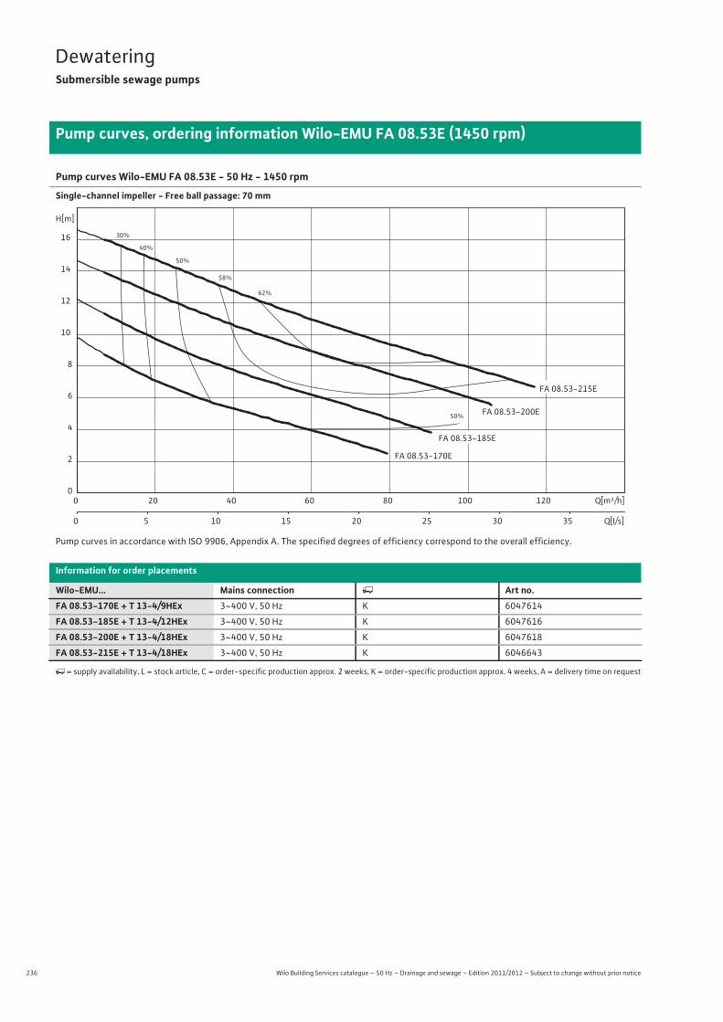
236 Wilo Building Services catalogue – 50 Hz – Drainage and sewage – Edition 2011/2012 – Subject to change without prior notice
DewateringSubmersible sewage pumps
Pump curves, ordering information Wilo-EMU FA 08.53E (1450 rpm)
Pump curves Wilo-EMU FA 08.53E - 50 Hz - 1450 rpm
Single-channel impeller - Free ball passage: 70 mm
Pump curves in accordance with ISO 9906, Appendix A. The specified degrees of efficiency correspond to the overall efficiency.
Information for order placements
Wilo-EMU... Mains connection � Art no.FA 08.53-170E + T 13-4/9HEx 3~400 V, 50 Hz K 6047614
FA 08.53-185E + T 13-4/12HEx 3~400 V, 50 Hz K 6047616
FA 08.53-200E + T 13-4/18HEx 3~400 V, 50 Hz K 6047618
FA 08.53-215E + T 13-4/18HEx 3~400 V, 50 Hz K 6046643
�= supply availability, L = stock article, C = order-specific production approx. 2 weeks, K = order-specific production approx. 4 weeks, A = delivery time on request
30%
40%
50%
50%
58%
62%
FA 08.53-215E
FA 08.53-200E
FA 08.53-185E
FA 08.53-170E
Q[m³/h]0 20 40 60 80 100 120
Q[l/s]0 5 10 15 20 25 30 35
H[m]
0
2
4
6
8
10
12
14
16

237
DewateringSubmersible sewage pumps
Wilo Building Services catalogue – 50 Hz – Drainage and sewage – Edition 2011/2012 – Subject to change without prior notice
Technical data Wilo-EMU FA 08.53E (1450 rpm)
Dew
ater
ing
FA 08.53-170E + T 13-4/9HEx
FA 08.53-185E +T 13-4/12HEx
FA 08.53-200E + T 13-4/18HEx
FA 08.53-215E + T 13-4/18HEx
3~400 V, 50 Hz 3~400 V, 50 Hz 3~400 V, 50 Hz 3~400 V, 50 Hz
Unit
Pressure connection DN 80 DN 80 DN 80 DN 80
Free ball passage mm 70 70 70 70
Max. volume flow Qmax / m3/h 79.3 90.6 106 117
Max. delivery head Hmax / m 9.8 12.2 14.7 16.6
Operating mode (immersed) S1 S1 S1 S1
Operating mode (non-immersed) S2-15 min. S2-15 min. S2-15 min. S2-15 min.
Max. immersion depth m 12.5 12.5 12.5 12.5
Protection class IP 68 IP 68 IP 68 IP 68
Fluid temperature T / °C +3 ... +40 +3 ... +40 +3 ... +40 +3 ... +40
Weight approx. m / kg 66.5 68.5 73.5 73.5
Motor data
Nominal current IN / A 4.2 5.1 9.2 9.2
Starting current IA / A 16 20 32 32
Nominal motor power P2 / kW 1.75 2.25 4 4
Power consumption P1 / kW 2.5 3 5 5
Activation type Direct Direct Direct Direct
Nominal speed n / rpm 1310 1350 1400 1400
Insulation class F F F F
Recommended switching frequency 1/h – – – –
Max. switching frequency 1/h 15 15 15 15
Permitted voltage tolerance % +/- 10 +/- 10 +/- 10 +/- 10
Cable
Length of connecting cable m 10 10 10 10
Cable type H07RN-F H07RN-F H07RN-F H07RN-F
Cable cross-section mm2 7G1,5 7G1,5 7G1,5 7G1,5
Type of connecting cable Non-detachable Non-detachable Non-detachable Non-detachable
Mains plug – – – –
Equipment/function
Float switch – – – –
Motor protection WSK WSK WSK WSK
Explosion protection ATEX ATEX ATEX ATEX
Materials
Static seal NBR NBR NBR NBR
Impeller EN-GJS-500-7 EN-GJS-500-7 EN-GJS-500-7 EN-GJS-500-7
Sealing on motor side NBR NBR NBR NBR
Mechanical seal SiC/SiC SiC/SiC SiC/SiC SiC/SiC
Motor housing EN-GJL-250 EN-GJL-250 EN-GJL-250 EN-GJL-250
Pump housing EN-GJL-250 EN-GJL-250 EN-GJL-250 EN-GJL-250
Pump shaft 1.4021 1.4021 1.4021 1.4021
P1 refers to the maximum power consumption. All of the data applies to 3~400 V, 50 Hz and a density of 1 kg/dm3.
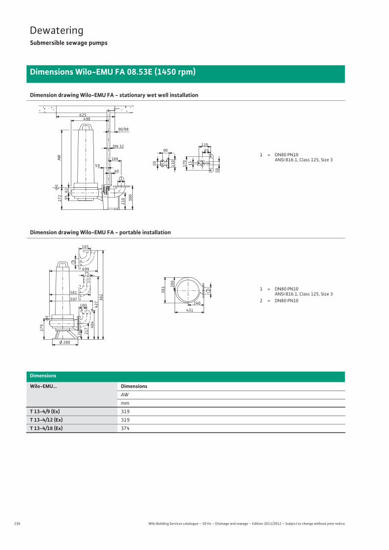
238 Wilo Building Services catalogue – 50 Hz – Drainage and sewage – Edition 2011/2012 – Subject to change without prior notice
DewateringSubmersible sewage pumps
Dimensions Wilo-EMU FA 08.53E (1450 rpm)
Dimension drawing Wilo-EMU FA - stationary wet well installation
Dimension drawing Wilo-EMU FA - portable installation
Dimensions
Wilo-EMU... DimensionsAW
mm
T 13-4/9 (Ex) 319
T 13-4/12 (Ex) 319
T 13-4/18 (Ex) 374
62
490
95 300
59
1
210
90/98
166
15
170
120 DN 32 69 90
272
50 50
40
625
110 A W
1 = DN80 PN10 ANSI B16.1, Class 125, Size 3
1
240
431
381 20
6
Ø 280
126 217 40
4427
100 597
75
279
382
699
165
2
5811 = DN80 PN10
ANSI B16.1, Class 125, Size 3 2 = DN80 PN10
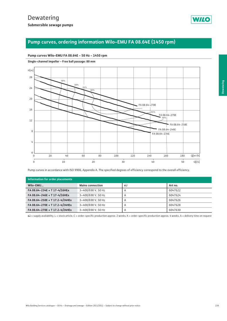
239
DewateringSubmersible sewage pumps
Dew
ater
ing
Pump curves, ordering information Wilo-EMU FA 08.64E (1450 rpm)
Wilo Building Services catalogue – 50 Hz – Drainage and sewage – Edition 2011/2012 – Subject to change without prior notice
Pump curves Wilo-EMU FA 08.64E - 50 Hz - 1450 rpm
Single-channel impeller - Free ball passage: 80 mm
Pump curves in accordance with ISO 9906, Appendix A. The specified degrees of efficiency correspond to the overall efficiency.
Information for order placements
Wilo-EMU... Mains connection � Art no.FA 08.64-234E + T 17-4/16HEx 3~400/690 V, 50 Hz A 6047622
FA 08.64-246E + T 17-4/16HEx 3~400/690 V, 50 Hz A 6047624
FA 08.64-258E + T 17.2-4/24HEx 3~400/690 V, 50 Hz A 6047626
FA 08.64-270E + T 17.2-4/24HEx 3~400/690 V, 50 Hz A 6047628
FA 08.64-278E + T 17.2-4/24HEx 3~400/690 V, 50 Hz A 6047630
�= supply availability, L = stock article, C = order-specific production approx. 2 weeks, K = order-specific production approx. 4 weeks, A = delivery time on request
50%
60%
60%
64%
64%
66%
FA 08.64-258E
FA 08.64-278E
FA 08.64-234E
FA 08.64-246E
FA 08.64-270E
Q[m³/h]0 20 40 60 80 100 120 140 160 180
Q[l/s]0 10 20 30 40 50
H[m]
0
4
8
12
16
20
24
28
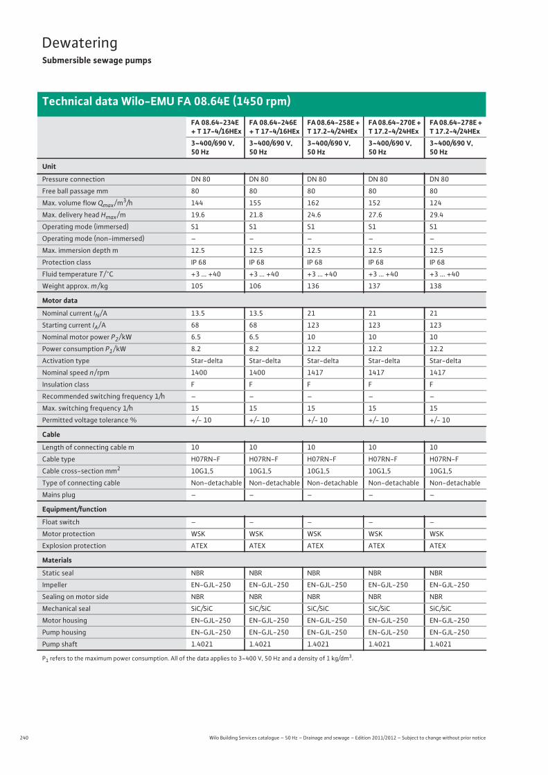
240 Wilo Building Services catalogue – 50 Hz – Drainage and sewage – Edition 2011/2012 – Subject to change without prior notice
DewateringSubmersible sewage pumps
Technical data Wilo-EMU FA 08.64E (1450 rpm)
FA 08.64-234E + T 17-4/16HEx
FA 08.64-246E + T 17-4/16HEx
FA 08.64-258E + T 17.2-4/24HEx
FA 08.64-270E + T 17.2-4/24HEx
FA 08.64-278E + T 17.2-4/24HEx
3~400/690 V, 50 Hz
3~400/690 V, 50 Hz
3~400/690 V, 50 Hz
3~400/690 V, 50 Hz
3~400/690 V, 50 Hz
Unit
Pressure connection DN 80 DN 80 DN 80 DN 80 DN 80
Free ball passage mm 80 80 80 80 80
Max. volume flow Qmax / m3/h 144 155 162 152 124
Max. delivery head Hmax / m 19.6 21.8 24.6 27.6 29.4
Operating mode (immersed) S1 S1 S1 S1 S1
Operating mode (non-immersed) – – – – –
Max. immersion depth m 12.5 12.5 12.5 12.5 12.5
Protection class IP 68 IP 68 IP 68 IP 68 IP 68
Fluid temperature T / °C +3 ... +40 +3 ... +40 +3 ... +40 +3 ... +40 +3 ... +40
Weight approx. m / kg 105 106 136 137 138
Motor data
Nominal current IN / A 13.5 13.5 21 21 21
Starting current IA / A 68 68 123 123 123
Nominal motor power P2 / kW 6.5 6.5 10 10 10
Power consumption P1 / kW 8.2 8.2 12.2 12.2 12.2
Activation type Star-delta Star-delta Star-delta Star-delta Star-delta
Nominal speed n / rpm 1400 1400 1417 1417 1417
Insulation class F F F F F
Recommended switching frequency 1/h – – – – –
Max. switching frequency 1/h 15 15 15 15 15
Permitted voltage tolerance % +/- 10 +/- 10 +/- 10 +/- 10 +/- 10
Cable
Length of connecting cable m 10 10 10 10 10
Cable type H07RN-F H07RN-F H07RN-F H07RN-F H07RN-F
Cable cross-section mm2 10G1,5 10G1,5 10G1,5 10G1,5 10G1,5
Type of connecting cable Non-detachable Non-detachable Non-detachable Non-detachable Non-detachable
Mains plug – – – – –
Equipment/function
Float switch – – – – –
Motor protection WSK WSK WSK WSK WSK
Explosion protection ATEX ATEX ATEX ATEX ATEX
Materials
Static seal NBR NBR NBR NBR NBR
Impeller EN-GJL-250 EN-GJL-250 EN-GJL-250 EN-GJL-250 EN-GJL-250
Sealing on motor side NBR NBR NBR NBR NBR
Mechanical seal SiC/SiC SiC/SiC SiC/SiC SiC/SiC SiC/SiC
Motor housing EN-GJL-250 EN-GJL-250 EN-GJL-250 EN-GJL-250 EN-GJL-250
Pump housing EN-GJL-250 EN-GJL-250 EN-GJL-250 EN-GJL-250 EN-GJL-250
Pump shaft 1.4021 1.4021 1.4021 1.4021 1.4021
P1 refers to the maximum power consumption. All of the data applies to 3~400 V, 50 Hz and a density of 1 kg/dm3.

241
DewateringSubmersible sewage pumps
Dew
ater
ing
Dimensions Wilo-EMU FA 08.64E (1450 rpm)
Wilo Building Services catalogue – 50 Hz – Drainage and sewage – Edition 2011/2012 – Subject to change without prior notice
Dimension drawing Wilo-EMU FA - stationary wet well installation
Dimension drawing Wilo-EMU FA - portable installation
Dimensions
Wilo-EMU... DimensionsAW
mm
T 17-4/16 (Ex) 411
T 17.2-4/24 (Ex) 510
76
504
100
300
59
1
210
90/98
166
15170
120DN 326990
286
50
5040
625
110AW
1 = DN80 PN10ANSI B16.1, Class 125, Size 3
1
245
445
407 21
1
Ø 280
126 22
2 409
432
100611
75
298
387
713
165
2
5951 = DN80 PN10
ANSI B16.1, Class 125, Size 32 = DN80 PN10
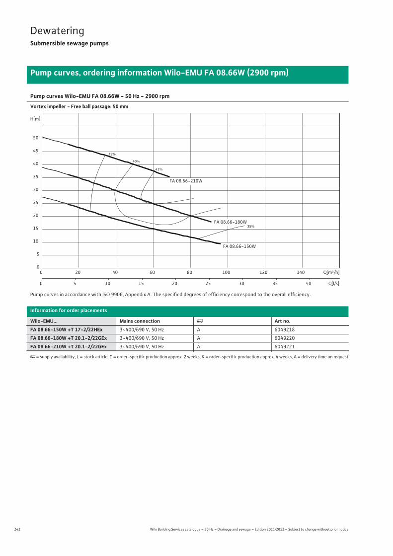
242 Wilo Building Services catalogue – 50 Hz – Drainage and sewage – Edition 2011/2012 – Subject to change without prior notice
DewateringSubmersible sewage pumps
Pump curves, ordering information Wilo-EMU FA 08.66W (2900 rpm)
Pump curves Wilo-EMU FA 08.66W - 50 Hz - 2900 rpm
Vortex impeller - Free ball passage: 50 mm
Pump curves in accordance with ISO 9906, Appendix A. The specified degrees of efficiency correspond to the overall efficiency.
Information for order placements
Wilo-EMU... Mains connection � Art no.FA 08.66-150W +T 17-2/22HEx 3~400/690 V, 50 Hz A 6049218
FA 08.66-180W +T 20.1-2/22GEx 3~400/690 V, 50 Hz A 6049220
FA 08.66-210W +T 20.1-2/22GEx 3~400/690 V, 50 Hz A 6049221
�= supply availability, L = stock article, C = order-specific production approx. 2 weeks, K = order-specific production approx. 4 weeks, A = delivery time on request
35%
35%
40%
42%
FA 08.66-180W
FA 08.66-210W
FA 08.66-150W
Q[m³/h]0 20 40 60 80 100 120 140
Q[l/s]0 5 10 15 20 25 30 35 40
H[m]
0
5
10
15
20
25
30
35
40
45
50

243
DewateringSubmersible sewage pumps
Wilo Building Services catalogue – 50 Hz – Drainage and sewage – Edition 2011/2012 – Subject to change without prior notice
Technical data Wilo-EMU FA 08.66W (2900 rpm)
Dew
ater
ing
FA 08.66-150W +T 17-2/22HEx
FA 08.66-180W +T 20.1-2/22GEx
FA 08.66-210W +T 20.1-2/22GEx
3~400/690 V, 50 Hz 3~400/690 V, 50 Hz 3~400/690 V, 50 Hz
Unit
Pressure connection DN 80 DN 80 DN 80
Free ball passage mm 50 50 50
Max. volume flow Qmax / m3/h 96 91 80
Max. delivery head Hmax / m 27.5 39 51
Operating mode (immersed) S1 S1 S1
Operating mode (non-immersed) – S2-15 min. S2-15 min.
Max. immersion depth m 12.5 12.5 12.5
Protection class IP 68 IP 68 IP 68
Fluid temperature T / °C +3 ... +40 +3 ... +40 +3 ... +40
Weight approx. m / kg – – –
Motor data
Nominal current IN / A 20.5 30 30
Starting current IA / A 57 72 72
Nominal motor power P2 / kW 10.5 15.5 15.5
Power consumption P1 / kW 12.3 18.6 18.6
Activation type Star-delta Star-delta Star-delta
Nominal speed n / rpm 2907 2900 2900
Insulation class F F F
Recommended switching frequency 1/h – – –
Max. switching frequency 1/h 15 15 15
Permitted voltage tolerance % +/- 10 +/- 10 +/- 10
Cable
Length of connecting cable m 10 10 10
Cable type H07RN-F NSSHÖU NSSHÖU
Cable cross-section mm2 10G1,5 2x 4x2,5 + 7x1,5 2x 4x2,5 + 7x1,5
Type of connecting cable Non-detachable Non-detachable Non-detachable
Mains plug – – –
Equipment/function
Float switch – – –
Motor protection WSK WSK WSK
Explosion protection ATEX ATEX ATEX
Materials
Static seal NBR NBR NBR
Impeller EN-GJS-500-7 EN-GJS-500-7 EN-GJS-500-7
Sealing on motor side NBR SiC/SiC SiC/SiC
Mechanical seal SiC/SiC SiC/SiC SiC/SiC
Motor housing EN-GJL-250 EN-GJL-250 EN-GJL-250
Pump housing EN-GJL-250 EN-GJL-250 EN-GJL-250
Pump shaft 1.4021 1.4021 1.4021
P1 refers to the maximum power consumption. All of the data applies to 3~400 V, 50 Hz and a density of 1 kg/dm3.
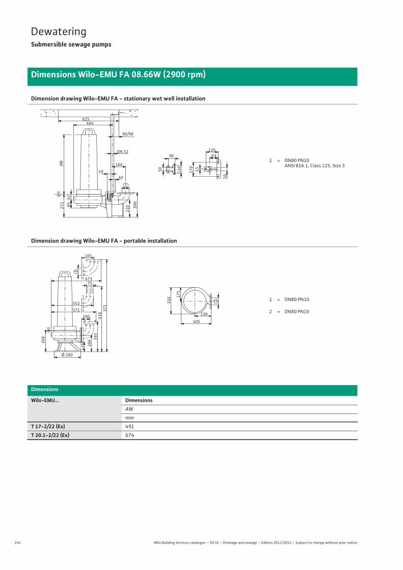
244 Wilo Building Services catalogue – 50 Hz – Drainage and sewage – Edition 2011/2012 – Subject to change without prior notice
DewateringSubmersible sewage pumps
Dimensions Wilo-EMU FA 08.66W (2900 rpm)
Dimension drawing Wilo-EMU FA - stationary wet well installation
Dimension drawing Wilo-EMU FA - portable installation
Dimensions
Wilo-EMU... DimensionsAW
mm
T 17-2/22 (Ex) 491
T 20.1-2/22 (Ex) 674
62
464
85 300
59
1
210
90/98
166
15
170
120 DN 32 69 90
272
50 50
40
625
110 A W
1 = DN80 PN10 ANSI B16.1, Class 125, Size 3
1
230
405
350 17
5
Ø 280
126 206 39
3416
100 571
75
268
371
673
165
2
5521 = DN80 PN10
2 = DN80 PN10
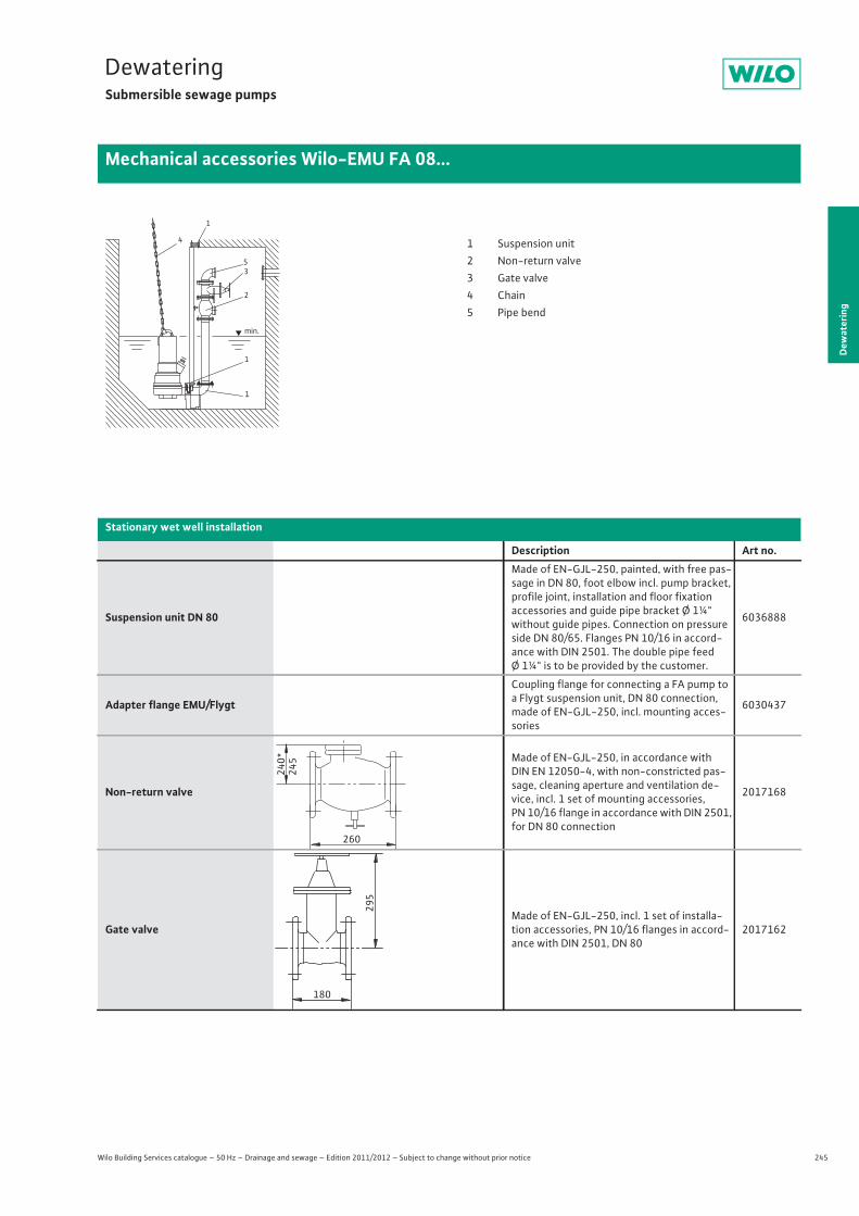
245
DewateringSubmersible sewage pumps
Dew
ater
ing
Mechanical accessories Wilo-EMU FA 08...
Wilo Building Services catalogue – 50 Hz – Drainage and sewage – Edition 2011/2012 – Subject to change without prior notice
Stationary wet well installation
Description Art no.
Suspension unit DN 80
Made of EN-GJL-250, painted, with free pas-sage in DN 80, foot elbow incl. pump bracket, profile joint, installation and floor fixationaccessories and guide pipe bracket Ø 1¼" without guide pipes. Connection on pressure side DN 80/65. Flanges PN 10/16 in accord-ance with DIN 2501. The double pipe feedØ 1¼" is to be provided by the customer.
6036888
Adapter flange EMU/Flygt
Coupling flange for connecting a FA pump to a Flygt suspension unit, DN 80 connection, made of EN-GJL-250, incl. mounting acces-sories
6030437
Non-return valve
Made of EN-GJL-250, in accordance with DIN EN 12050-4, with non-constricted pas-sage, cleaning aperture and ventilation de-vice, incl. 1 set of mounting accessories, PN 10/16 flange in accordance with DIN 2501, for DN 80 connection
2017168
Gate valveMade of EN-GJL-250, incl. 1 set of installa-tion accessories, PN 10/16 flanges in accord-ance with DIN 2501, DN 80
2017162
1
4
53
2
1
1
min.
1 Suspension unit2 Non-return valve3 Gate valve4 Chain5 Pipe bend
240*
245
260
295
180
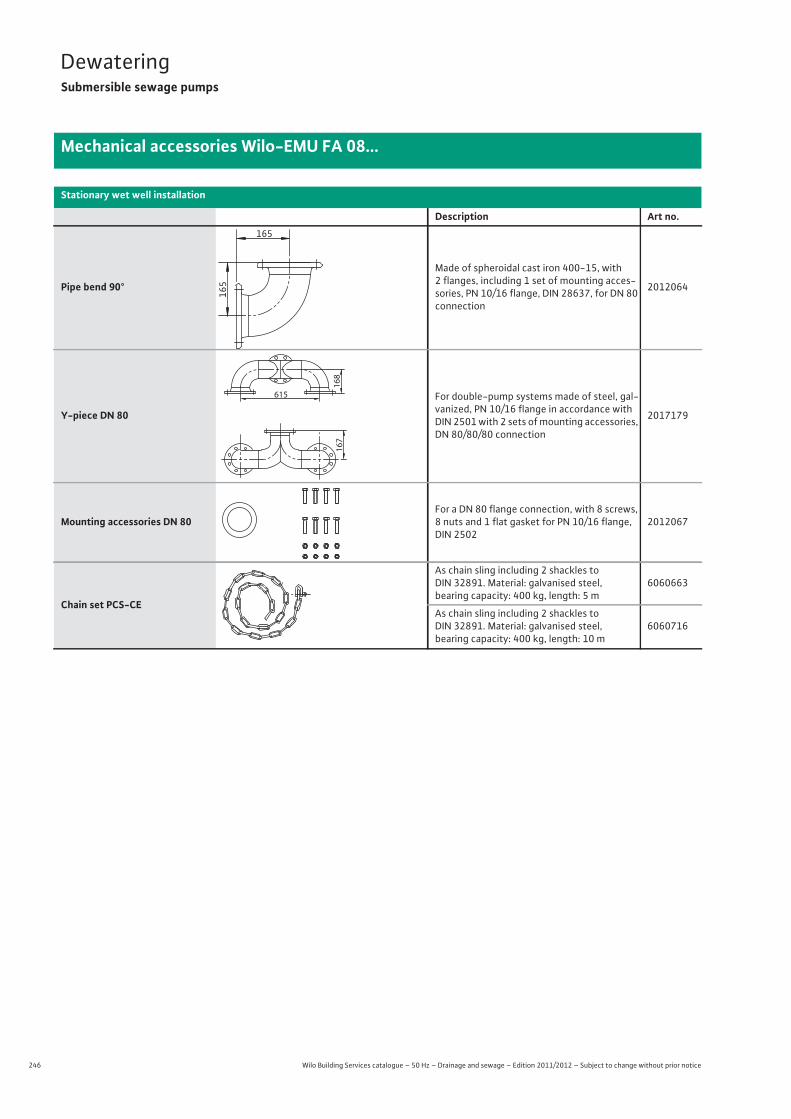
246 Wilo Building Services catalogue – 50 Hz – Drainage and sewage – Edition 2011/2012 – Subject to change without prior notice
DewateringSubmersible sewage pumps
Mechanical accessories Wilo-EMU FA 08...
Pipe bend 90°
Made of spheroidal cast iron 400-15, with2 flanges, including 1 set of mounting acces-sories, PN 10/16 flange, DIN 28637, for DN 80 connection
2012064
Y-piece DN 80
For double-pump systems made of steel, gal-vanized, PN 10/16 flange in accordance with DIN 2501 with 2 sets of mounting accessories, DN 80/80/80 connection
2017179
Mounting accessories DN 80For a DN 80 flange connection, with 8 screws, 8 nuts and 1 flat gasket for PN 10/16 flange, DIN 2502
2012067
Chain set PCS-CE
As chain sling including 2 shackles to DIN 32891. Material: galvanised steel, bearing capacity: 400 kg, length: 5 m
6060663
As chain sling including 2 shackles to DIN 32891. Material: galvanised steel, bearing capacity: 400 kg, length: 10 m
6060716
Stationary wet well installation
Description Art no.165
165
167
615
168
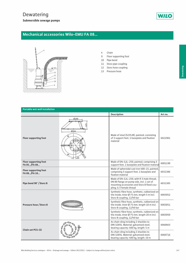
247
DewateringSubmersible sewage pumps
Dew
ater
ing
Mechanical accessories Wilo-EMU FA 08...
Wilo Building Services catalogue – 50 Hz – Drainage and sewage – Edition 2011/2012 – Subject to change without prior notice
13
12
11
10
9
min.
44 Chain9 Floor supporting foot10 Pipe bend11 Storz pipe coupling12 Storz hose coupling13 Pressure hose
Portable wet well installation
Description Art no.
Floor supporting footMade of steel (S235JR), painted, consisting of 3 support feet, 1 baseplate and fixation material
6022981
Floor supporting footFA 05.../FA 08...
Made of EN-GJL-250, painted, comprising 3 support feet, 1 baseplate and fixation material 6001190
Floor supporting footFA 08.../FA 10...
Made of spheroidal cast iron 400-15, painted, comprising 3 support feet, 1 baseplate and fixation material
6031386
Pipe bend 90° / Storz B
Made of EN-GJL-250, with R 3 male thread, DN 80 flange on pump side, incl. 1 set of mounting accessories and Storz B fixed cou-pling, G 3 female thread
6031385
Pressure hose / Storz B
Synthetic fibre hose, synthetic, rubberized on the inside, inner Ø 75 mm, length 5 m incl. Storz B coupling, 12/40 bar
6003052
Synthetic fibre hose, synthetic, rubberized on the inside, inner Ø 75 mm, length 10 m incl. Storz B coupling, 12/40 bar
6003051
Synthetic fibre hose, synthetic, rubberized on the inside, inner Ø 75 mm, length 20 m incl. Storz B coupling, 12/40 bar
6003050
Chain set PCS-CE
As chain sling including 2 shackles to DIN 32891. Material: galvanised steel, bearing capacity: 400 kg, length: 5 m
6060663
As chain sling including 2 shackles to DIN 32891. Material: galvanised steel, bearing capacity: 400 kg, length: 10 m
6060716
Ø159
Ø344
35
Ø190
124
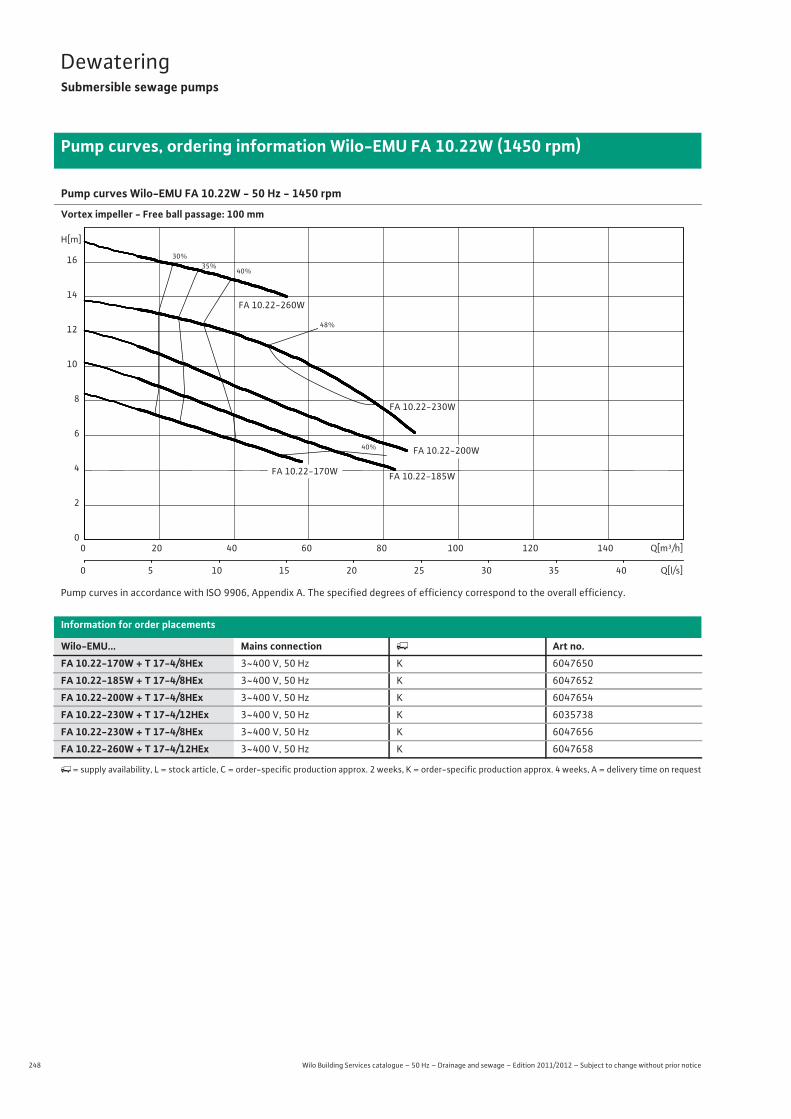
248 Wilo Building Services catalogue – 50 Hz – Drainage and sewage – Edition 2011/2012 – Subject to change without prior notice
DewateringSubmersible sewage pumps
Pump curves, ordering information Wilo-EMU FA 10.22W (1450 rpm)
Pump curves Wilo-EMU FA 10.22W - 50 Hz - 1450 rpm
Vortex impeller - Free ball passage: 100 mm
Pump curves in accordance with ISO 9906, Appendix A. The specified degrees of efficiency correspond to the overall efficiency.
Information for order placements
Wilo-EMU... Mains connection � Art no.FA 10.22-170W + T 17-4/8HEx 3~400 V, 50 Hz K 6047650
FA 10.22-185W + T 17-4/8HEx 3~400 V, 50 Hz K 6047652
FA 10.22-200W + T 17-4/8HEx 3~400 V, 50 Hz K 6047654
FA 10.22-230W + T 17-4/12HEx 3~400 V, 50 Hz K 6035738
FA 10.22-230W + T 17-4/8HEx 3~400 V, 50 Hz K 6047656
FA 10.22-260W + T 17-4/12HEx 3~400 V, 50 Hz K 6047658
�= supply availability, L = stock article, C = order-specific production approx. 2 weeks, K = order-specific production approx. 4 weeks, A = delivery time on request
30%35%
40%
40%
48%
FA 10.22-200W
FA 10.22-260W
FA 10.22-185W
FA 10.22-230W
FA 10.22-170W
Q[m³/h]0 20 40 60 80 100 120 140
Q[l/s]0 5 10 15 20 25 30 35 40
H[m]
0
2
4
6
8
10
12
14
16

249
DewateringSubmersible sewage pumps
Wilo Building Services catalogue – 50 Hz – Drainage and sewage – Edition 2011/2012 – Subject to change without prior notice
Technical data Wilo-EMU FA 10.22W (1450 rpm)
Dew
ater
ing
FA 10.22-170W + T 17-4/8HEx
FA 10.22-185W + T 17-4/8HEx
FA 10.22-200W + T 17-4/8HEx
FA 10.22-230W + T 17-4/12HEx
FA 10.22-230W + T 17-4/8HEx
FA 10.22-260W + T 17-4/12HEx
3~400 V, 50 Hz 3~400 V, 50 Hz 3~400 V, 50 Hz 3~400 V, 50 Hz 3~400 V, 50 Hz 3~400 V, 50 Hz
Unit
Pressure connection DN 100 DN 100 DN 100 DN 100 DN 100 DN 100
Free ball passage mm 100 100 100 100 100 100
Max. volume flow Qmax / m3/h 58 82.8 86 88.1 88.1 85.3
Max. delivery head Hmax / m 8.5 10.2 12.1 13.9 13.9 17.3
Operating mode (immersed) S1 S1 S1 S1 S1 S1
Operating mode(non-immersed) – – – – – –
Max. immersion depth m 12.5 12.5 12.5 12.5 12.5 12.5
Protection class IP 68 IP 68 IP 68 IP 68 IP 68 IP 68
Fluid temperature T / °C +3 ... +40 +3 ... +40 +3 ... +40 +3 ... +40 +3 ... +40 +3 ... +40
Weight approx. m / kg 73 73 74 84 76 86
Motor data
Nominal current IN / A 7.9 7.9 7.9 9.4 7.9 9.4
Starting current IA / A 37 37 37 47 37 47
Nominal motor power P2 / kW 3.5 3.5 3.5 4.5 3.5 4.5
Power consumption P1 / kW 4.5 4.5 4.5 5.8 4.5 4.5
Activation type Direct Direct Direct Direct Direct Direct
Nominal speed n / rpm 1410 1410 1410 1405 1410 1405
Insulation class F F F F F F
Recommended switchingfrequency 1/h – – – – – –
Max. switching frequency 1/h 15 15 15 15 15 15
Permitted voltage tolerance % +/- 10 +/- 10 +/- 10 +/- 10 +/- 10 +/- 10
Cable
Length of connecting cable m 10 10 10 10 10 10
Cable type H07RN-F H07RN-F H07RN-F H07RN-F H07RN-F H07RN-F
Cable cross-section mm2 7G1,5 7G1,5 7G1,5 7G1,5 7G1,5 7G1,5
Type of connecting cable Non-detachable Non-detachable Non-detachable Non-detachable Non-detachable Non-detachable
Mains plug – – – – – –
Equipment/function
Float switch – – – – – –
Motor protection WSK WSK WSK WSK WSK WSK
Explosion protection ATEX ATEX ATEX ATEX ATEX ATEX
Materials
Static seal NBR NBR NBR NBR NBR NBR
Impeller EN-GJL-250 EN-GJL-250 EN-GJL-250 EN-GJL-250 EN-GJL-250 EN-GJL-250
Sealing on motor side NBR NBR NBR NBR NBR NBR
Mechanical seal SiC/SiC SiC/SiC SiC/SiC SiC/SiC SiC/SiC SiC/SiC
Motor housing EN-GJL-250 EN-GJL-250 EN-GJL-250 EN-GJL-250 EN-GJL-250 EN-GJL-250
Pump housing EN-GJL-250 EN-GJL-250 EN-GJL-250 EN-GJL-250 EN-GJL-250 EN-GJL-250
Pump shaft 1.4021 1.4021 1.4021 1.4021 1.4021 1.4021
P1 refers to the maximum power consumption. All of the data applies to 3~400 V, 50 Hz and a density of 1 kg/dm3.

250 Wilo Building Services catalogue – 50 Hz – Drainage and sewage – Edition 2011/2012 – Subject to change without prior notice
DewateringSubmersible sewage pumps
Dimensions Wilo-EMU FA 10.22W (1450 rpm)
Dimension drawing Wilo-EMU FA - stationary wet well installation
Dimension drawing Wilo-EMU FA - portable installation
Dimensions
Wilo-EMU... DimensionsAW
mm
T 17-4/8 (Ex) 338
T 17-4/12 (Ex) 373
1 = DN100 PN10ANSI B16.1, Class 125, Size 4
92
439
117
325
65
1
225
90/ 96
176 15190
160DN 32 10990
317
50
110
44
AW
800
50
1 = DN100 PN10 ANSI B16.1, Class 125, Size 4
2 = DN100 PN10
1
200374
340170
Ø 280
126 238440
489
120
588
100
330
419
667
180
2
554
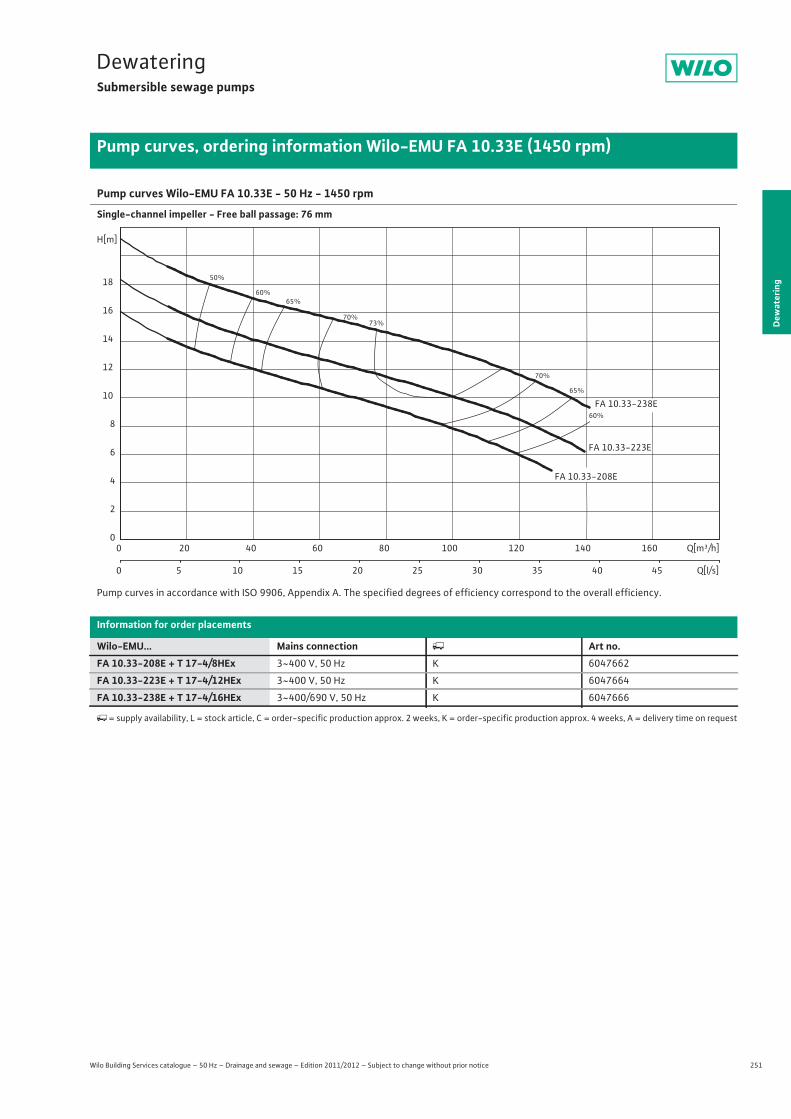
251
DewateringSubmersible sewage pumps
Dew
ater
ing
Pump curves, ordering information Wilo-EMU FA 10.33E (1450 rpm)
Wilo Building Services catalogue – 50 Hz – Drainage and sewage – Edition 2011/2012 – Subject to change without prior notice
Pump curves Wilo-EMU FA 10.33E - 50 Hz - 1450 rpm
Single-channel impeller - Free ball passage: 76 mm
Pump curves in accordance with ISO 9906, Appendix A. The specified degrees of efficiency correspond to the overall efficiency.
Information for order placements
Wilo-EMU... Mains connection � Art no.FA 10.33-208E + T 17-4/8HEx 3~400 V, 50 Hz K 6047662
FA 10.33-223E + T 17-4/12HEx 3~400 V, 50 Hz K 6047664
FA 10.33-238E + T 17-4/16HEx 3~400/690 V, 50 Hz K 6047666
�= supply availability, L = stock article, C = order-specific production approx. 2 weeks, K = order-specific production approx. 4 weeks, A = delivery time on request
50%
60%
60%
65%
65%
70%
70%
73%
FA 10.33-238E
FA 10.33-208E
FA 10.33-223E
Q[m³/h]0 20 40 60 80 100 120 140 160
Q[l/s]0 5 10 15 20 25 30 35 40 45
H[m]
0
2
4
6
8
10
12
14
16
18

252 Wilo Building Services catalogue – 50 Hz – Drainage and sewage – Edition 2011/2012 – Subject to change without prior notice
DewateringSubmersible sewage pumps
Technical data Wilo-EMU FA 10.33E (1450 rpm)
FA 10.33-208E + T 17-4/8HEx
FA 10.33-223E + T 17-4/12HEx
FA 10.33-238E + T 17-4/16HEx
3~400 V, 50 Hz 3~400 V, 50 Hz 3~400/690 V, 50 Hz
Unit
Pressure connection DN 100 DN 100 DN 100
Free ball passage mm 76 76 76
Max. volume flow Qmax / m3/h 130 140 141
Max. delivery head Hmax / m 16.1 18.3 21.2
Operating mode (immersed) S1 S1 S1
Operating mode (non-immersed) – – –
Max. immersion depth m 12.5 12.5 12.5
Protection class IP 68 IP 68 IP 68
Fluid temperature T / °C +3 ... +40 +3 ... +40 +3 ... +40
Weight approx. m / kg 73 81 92
Motor data
Nominal current IN / A 7.9 9.4 13.5
Starting current IA / A 37 47 68
Nominal motor power P2 / kW 3.5 4.5 6.5
Power consumption P1 / kW 4.5 5.8 8.2
Activation type Direct Direct Star-delta
Nominal speed n / rpm 1410 1405 1400
Insulation class F F F
Recommended switching frequency 1/h – – –
Max. switching frequency 1/h 15 15 15
Permitted voltage tolerance % +/- 10 +/- 10 +/- 10
Cable
Length of connecting cable m 10 10 10
Cable type H07RN-F H07RN-F H07RN-F
Cable cross-section mm2 7G1,5 7G1,5 10G1,5
Type of connecting cable Non-detachable Non-detachable Non-detachable
Mains plug – – –
Equipment/function
Float switch – – –
Motor protection WSK WSK WSK
Explosion protection ATEX ATEX ATEX
Materials
Static seal NBR NBR NBR
Impeller EN-GJS-500-7 EN-GJS-500-7 EN-GJS-500-7
Sealing on motor side NBR NBR NBR
Mechanical seal SiC/SiC SiC/SiC SiC/SiC
Motor housing EN-GJL-250 EN-GJL-250 EN-GJL-250
Pump housing EN-GJL-250 EN-GJL-250 EN-GJL-250
Pump shaft 1.4021 1.4021 1.4021
P1 refers to the maximum power consumption. All of the data applies to 3~400 V, 50 Hz and a density of 1 kg/dm3.
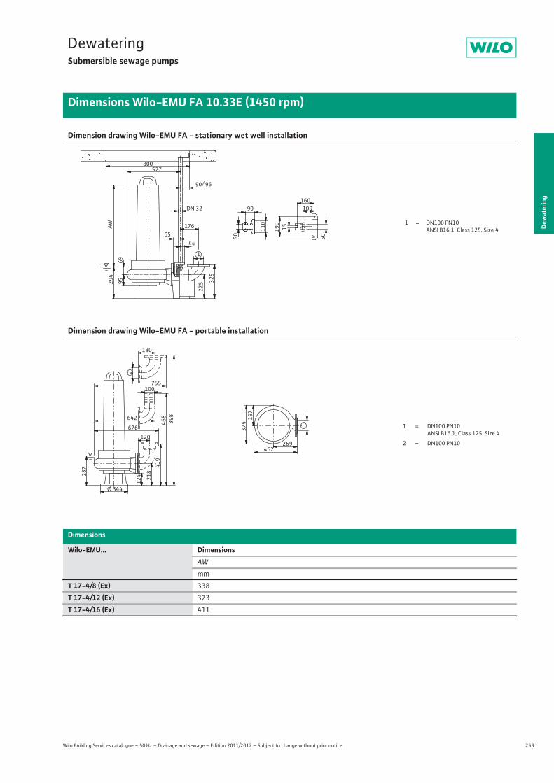
253
DewateringSubmersible sewage pumps
Dew
ater
ing
Dimensions Wilo-EMU FA 10.33E (1450 rpm)
Wilo Building Services catalogue – 50 Hz – Drainage and sewage – Edition 2011/2012 – Subject to change without prior notice
Dimension drawing Wilo-EMU FA - stationary wet well installation
Dimension drawing Wilo-EMU FA - portable installation
Dimensions
Wilo-EMU... DimensionsAW
mm
T 17-4/8 (Ex) 338
T 17-4/12 (Ex) 373
T 17-4/16 (Ex) 411
1 = DN100 PN10ANSI B16.1, Class 125, Size 4
69
527
95 325
65
1
225
90/ 96
176 15190
160DN 32 10990
294
50
110
44
AW
800
50
1 = DN100 PN10 ANSI B16.1, Class 125, Size 4
2 = DN100 PN10
1
269462
374197
Ø 344
124 21
841
946
8
120676
100
287
398
755
180
2
642
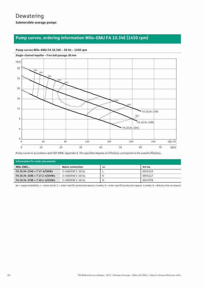
254 Wilo Building Services catalogue – 50 Hz – Drainage and sewage – Edition 2011/2012 – Subject to change without prior notice
DewateringSubmersible sewage pumps
Pump curves, ordering information Wilo-EMU FA 10.34E (1450 rpm)
Pump curves Wilo-EMU FA 10.34E - 50 Hz - 1450 rpm
Single-channel impeller - Free ball passage: 80 mm
Pump curves in accordance with ISO 9906, Appendix A. The specified degrees of efficiency correspond to the overall efficiency.
Information for order placements
Wilo-EMU... Mains connection � Art no.FA 10.34-234E + T 17-4/16HEx 3~400/690 V, 50 Hz L 6045118
FA 10.34-258E + T 17.2-4/24HEx 3~400/690 V, 50 Hz K 6045117
FA 10.34-278E + T 20.1-4/22GEx 3~400/690 V, 50 Hz K 6047678
�= supply availability, L = stock article, C = order-specific production approx. 2 weeks, K = order-specific production approx. 4 weeks, A = delivery time on request
40%50%
50%
60%
60%
65%
65%
68%
FA 10.34-258E
FA 10.34-234E
FA 10.34-278E
Q[m³/h]0 40 80 120 160 200 240
Q[l/s]0 10 20 30 40 50 60 70
H[m]
0
4
8
12
16
20
24
28
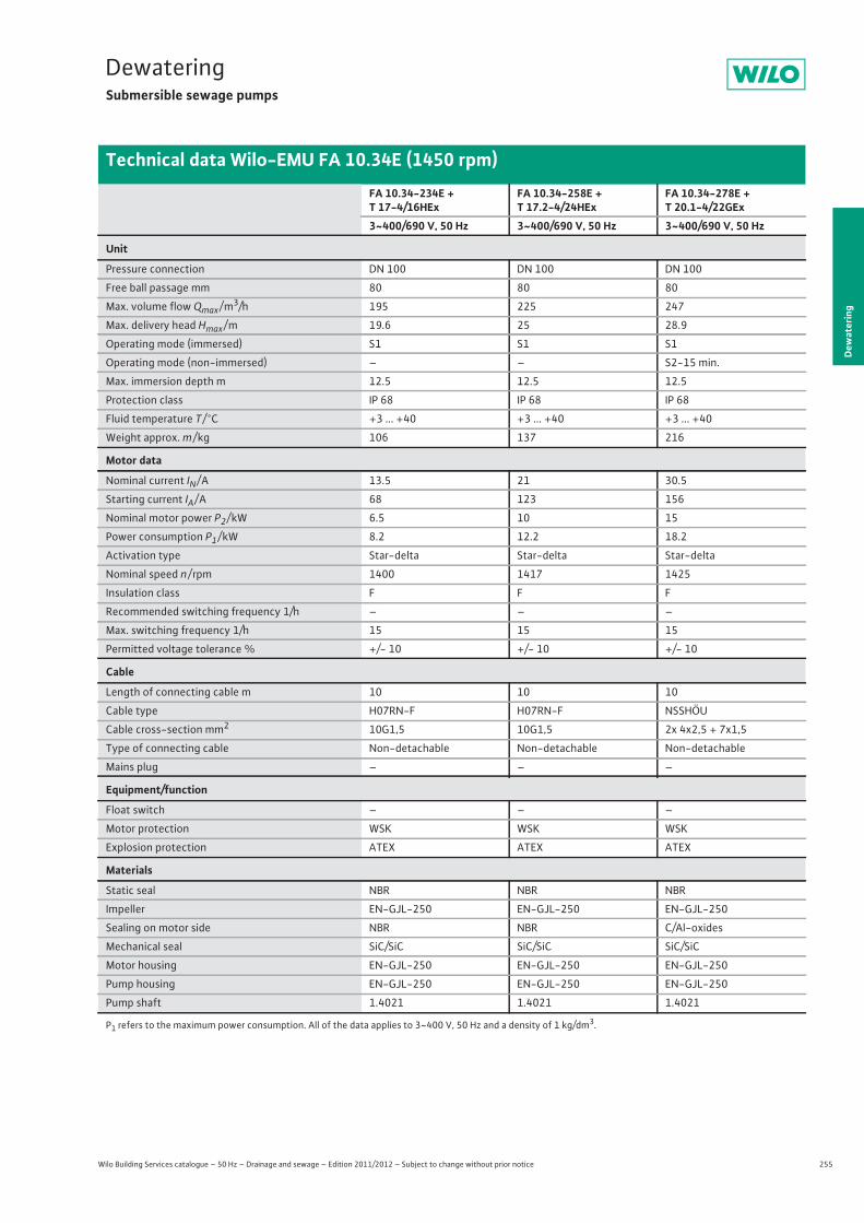
255
DewateringSubmersible sewage pumps
Wilo Building Services catalogue – 50 Hz – Drainage and sewage – Edition 2011/2012 – Subject to change without prior notice
Technical data Wilo-EMU FA 10.34E (1450 rpm)
Dew
ater
ing
FA 10.34-234E + T 17-4/16HEx
FA 10.34-258E + T 17.2-4/24HEx
FA 10.34-278E + T 20.1-4/22GEx
3~400/690 V, 50 Hz 3~400/690 V, 50 Hz 3~400/690 V, 50 Hz
Unit
Pressure connection DN 100 DN 100 DN 100
Free ball passage mm 80 80 80
Max. volume flow Qmax / m3/h 195 225 247
Max. delivery head Hmax / m 19.6 25 28.9
Operating mode (immersed) S1 S1 S1
Operating mode (non-immersed) – – S2-15 min.
Max. immersion depth m 12.5 12.5 12.5
Protection class IP 68 IP 68 IP 68
Fluid temperature T / °C +3 ... +40 +3 ... +40 +3 ... +40
Weight approx. m / kg 106 137 216
Motor data
Nominal current IN / A 13.5 21 30.5
Starting current IA / A 68 123 156
Nominal motor power P2 / kW 6.5 10 15
Power consumption P1 / kW 8.2 12.2 18.2
Activation type Star-delta Star-delta Star-delta
Nominal speed n / rpm 1400 1417 1425
Insulation class F F F
Recommended switching frequency 1/h – – –
Max. switching frequency 1/h 15 15 15
Permitted voltage tolerance % +/- 10 +/- 10 +/- 10
Cable
Length of connecting cable m 10 10 10
Cable type H07RN-F H07RN-F NSSHÖU
Cable cross-section mm2 10G1,5 10G1,5 2x 4x2,5 + 7x1,5
Type of connecting cable Non-detachable Non-detachable Non-detachable
Mains plug – – –
Equipment/function
Float switch – – –
Motor protection WSK WSK WSK
Explosion protection ATEX ATEX ATEX
Materials
Static seal NBR NBR NBR
Impeller EN-GJL-250 EN-GJL-250 EN-GJL-250
Sealing on motor side NBR NBR C/Al-oxides
Mechanical seal SiC/SiC SiC/SiC SiC/SiC
Motor housing EN-GJL-250 EN-GJL-250 EN-GJL-250
Pump housing EN-GJL-250 EN-GJL-250 EN-GJL-250
Pump shaft 1.4021 1.4021 1.4021
P1 refers to the maximum power consumption. All of the data applies to 3~400 V, 50 Hz and a density of 1 kg/dm3.
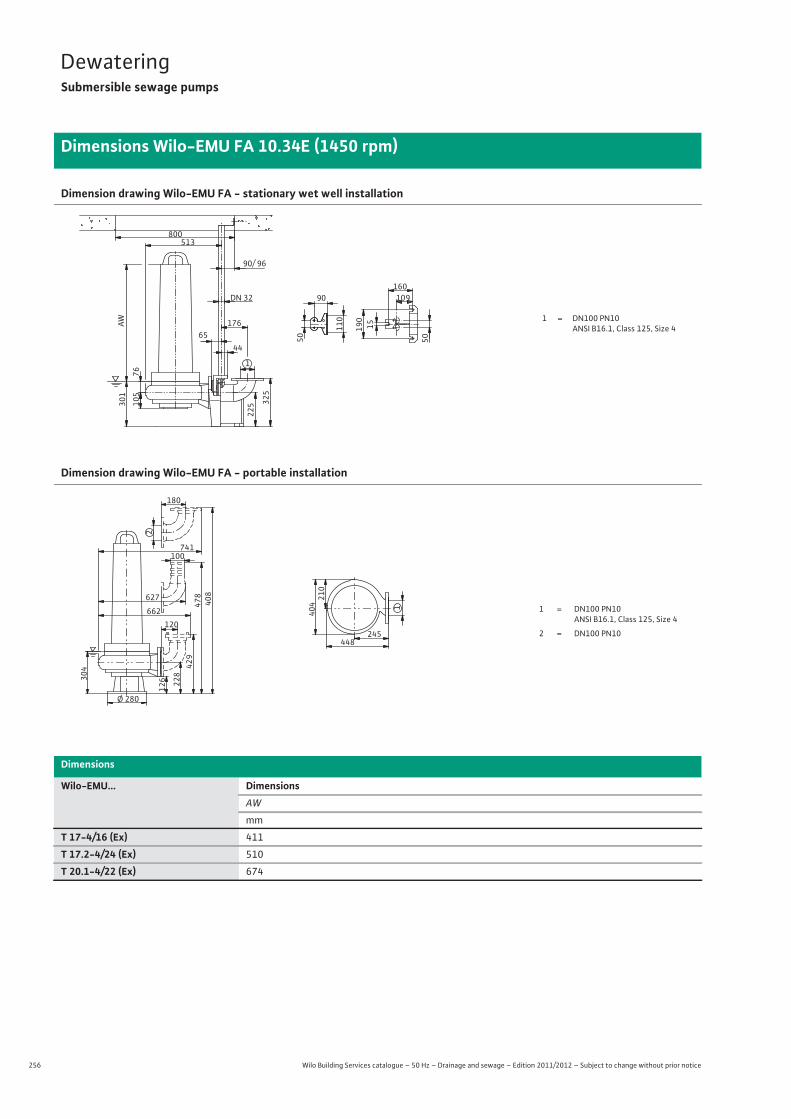
256 Wilo Building Services catalogue – 50 Hz – Drainage and sewage – Edition 2011/2012 – Subject to change without prior notice
DewateringSubmersible sewage pumps
Dimensions Wilo-EMU FA 10.34E (1450 rpm)
Dimension drawing Wilo-EMU FA - stationary wet well installation
Dimension drawing Wilo-EMU FA - portable installation
Dimensions
Wilo-EMU... DimensionsAW
mm
T 17-4/16 (Ex) 411
T 17.2-4/24 (Ex) 510
T 20.1-4/22 (Ex) 674
1 = DN100 PN10ANSI B16.1, Class 125, Size 4
76
513
105
325
65
1
225
90/ 96
176 15190
160DN 32 10990
301
50
110
44
AW
800
50
1 = DN100 PN10 ANSI B16.1, Class 125, Size 4
2 = DN100 PN10
1
245448
404
210
Ø 280
126 22
842
947
8
120662
100
304
408
741
180
2
627
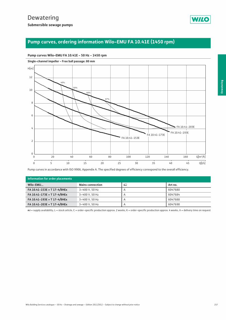
257
DewateringSubmersible sewage pumps
Dew
ater
ing
Pump curves, ordering information Wilo-EMU FA 10.41E (1450 rpm)
Wilo Building Services catalogue – 50 Hz – Drainage and sewage – Edition 2011/2012 – Subject to change without prior notice
Pump curves Wilo-EMU FA 10.41E - 50 Hz - 1450 rpm
Single-channel impeller - Free ball passage: 80 mm
Pump curves in accordance with ISO 9906, Appendix A. The specified degrees of efficiency correspond to the overall efficiency.
Information for order placements
Wilo-EMU... Mains connection � Art no.FA 10.41-153E + T 17-4/8HEx 3~400 V, 50 Hz A 6047680
FA 10.41-173E + T 17-4/8HEx 3~400 V, 50 Hz A 6047684
FA 10.41-193E + T 17-4/8HEx 3~400 V, 50 Hz A 6047688
FA 10.41-203E + T 17-4/8HEx 3~400 V, 50 Hz A 6047690
�= supply availability, L = stock article, C = order-specific production approx. 2 weeks, K = order-specific production approx. 4 weeks, A = delivery time on request
40%
50%
60%
67%
FA 10.41-153E
FA 10.41-203E
FA 10.41-193EFA 10.41-173E
Q[m³/h]0 20 40 60 80 100 120 140 160
Q[l/s]0 5 10 15 20 25 30 35 40 45
H[m]
0
2
4
6
8
10
12

258 Wilo Building Services catalogue – 50 Hz – Drainage and sewage – Edition 2011/2012 – Subject to change without prior notice
DewateringSubmersible sewage pumps
Technical data Wilo-EMU FA 10.41E (1450 rpm)
FA 10.41-153E + T 17-4/8HEx
FA 10.41-173E + T 17-4/8HEx
FA 10.41-193E + T 17-4/8HEx
FA 10.41-203E + T 17-4/8HEx
3~400 V, 50 Hz 3~400 V, 50 Hz 3~400 V, 50 Hz 3~400 V, 50 Hz
Unit
Pressure connection DN 100 DN 100 DN 100 DN 100
Free ball passage mm 80 80 80 80
Max. volume flow Qmax / m3/h 90 117 142 148
Max. delivery head Hmax / m 7.6 9.8 11.4 12.8
Operating mode (immersed) S1 S1 S1 S1
Operating mode (non-immersed) – – – –
Max. immersion depth m 12.5 12.5 12.5 12.5
Protection class IP 68 IP 68 IP 68 IP 68
Fluid temperature T / °C +3 ... +40 +3 ... +40 +3 ... +40 +3 ... +40
Weight approx. m / kg 69.5 70 70.5 70.5
Motor data
Nominal current IN / A 7.9 7.9 7.9 7.9
Starting current IA / A 37 37 37 37
Nominal motor power P2 / kW 3.5 3.5 3.5 3.5
Power consumption P1 / kW 4.5 4.5 4.5 4.5
Activation type Direct Direct Direct Direct
Nominal speed n / rpm 1410 1410 1410 1410
Insulation class F F F F
Recommended switching frequency 1/h – – – –
Max. switching frequency 1/h 15 15 15 15
Permitted voltage tolerance % +/- 10 +/- 10 +/- 10 +/- 10
Cable
Length of connecting cable m 10 10 10 10
Cable type H07RN-F H07RN-F H07RN-F H07RN-F
Cable cross-section mm2 7G1,5 7G1,5 7G1,5 7G1,5
Type of connecting cable Non-detachable Non-detachable Non-detachable Non-detachable
Mains plug – – – –
Equipment/function
Float switch – – – –
Motor protection WSK WSK WSK WSK
Explosion protection ATEX ATEX ATEX ATEX
Materials
Static seal NBR NBR NBR NBR
Impeller EN-GJL-250 EN-GJL-250 EN-GJL-250 EN-GJL-250
Sealing on motor side NBR NBR NBR NBR
Mechanical seal SiC/SiC SiC/SiC SiC/SiC SiC/SiC
Motor housing EN-GJL-250 EN-GJL-250 EN-GJL-250 EN-GJL-250
Pump housing EN-GJL-250 EN-GJL-250 EN-GJL-250 EN-GJL-250
Pump shaft 1.4021 1.4021 1.4021 1.4021
P1 refers to the maximum power consumption. All of the data applies to 3~400 V, 50 Hz and a density of 1 kg/dm3.

259
DewateringSubmersible sewage pumps
Dew
ater
ing
Dimensions Wilo-EMU FA 10.41E (1450 rpm)
Wilo Building Services catalogue – 50 Hz – Drainage and sewage – Edition 2011/2012 – Subject to change without prior notice
Dimension drawing Wilo-EMU FA - stationary wet well installation
Dimension drawing Wilo-EMU FA - portable installation
Dimensions
Wilo-EMU... DimensionsAW
mm
T 17-4/8 (Ex) 410
1 = DN100 PN10ANSI B16.1, Class 125, Size 4
75
527
94 325
65
1
225
90/ 96
176 15190
160DN 32 10990
300
50
110
44
AW
800
50
1 = DN100 PN10 ANSI B16.1, Class 125, Size 4
2 = DN100 PN10
1
270462
364203
Ø 320
124 218419
468
120
676
100
293
398
755
180
2
642
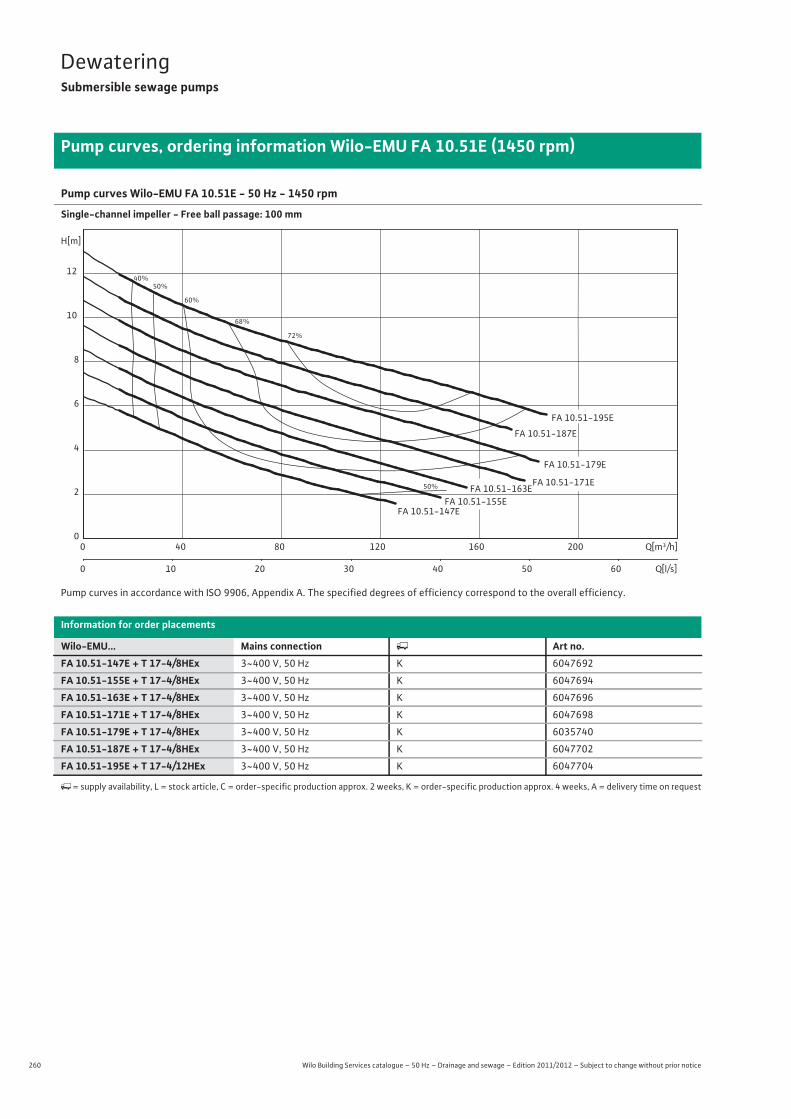
260 Wilo Building Services catalogue – 50 Hz – Drainage and sewage – Edition 2011/2012 – Subject to change without prior notice
DewateringSubmersible sewage pumps
Pump curves, ordering information Wilo-EMU FA 10.51E (1450 rpm)
Pump curves Wilo-EMU FA 10.51E - 50 Hz - 1450 rpm
Single-channel impeller - Free ball passage: 100 mm
Pump curves in accordance with ISO 9906, Appendix A. The specified degrees of efficiency correspond to the overall efficiency.
Information for order placements
Wilo-EMU... Mains connection � Art no.FA 10.51-147E + T 17-4/8HEx 3~400 V, 50 Hz K 6047692
FA 10.51-155E + T 17-4/8HEx 3~400 V, 50 Hz K 6047694
FA 10.51-163E + T 17-4/8HEx 3~400 V, 50 Hz K 6047696
FA 10.51-171E + T 17-4/8HEx 3~400 V, 50 Hz K 6047698
FA 10.51-179E + T 17-4/8HEx 3~400 V, 50 Hz K 6035740
FA 10.51-187E + T 17-4/8HEx 3~400 V, 50 Hz K 6047702
FA 10.51-195E + T 17-4/12HEx 3~400 V, 50 Hz K 6047704
�= supply availability, L = stock article, C = order-specific production approx. 2 weeks, K = order-specific production approx. 4 weeks, A = delivery time on request
40%50%
50%
60%
68%
72%
FA 10.51-187E
FA 10.51-171E
FA 10.51-195E
FA 10.51-147EFA 10.51-155E
FA 10.51-163E
FA 10.51-179E
Q[m³/h]0 40 80 120 160 200
Q[l/s]0 10 20 30 40 50 60
H[m]
0
2
4
6
8
10
12

261
DewateringSubmersible sewage pumps
Wilo Building Services catalogue – 50 Hz – Drainage and sewage – Edition 2011/2012 – Subject to change without prior notice
Technical data Wilo-EMU FA 10.51E (1450 rpm)
Dew
ater
ing
FA 10.51-147E + T 17-4/8HEx
FA 10.51-155E + T 17-4/8HEx
FA 10.51-163E + T 17-4/8HEx
3~400 V, 50 Hz 3~400 V, 50 Hz 3~400 V, 50 Hz
Unit
Pressure connection DN 100 DN 100 DN 100
Free ball passage mm 100 100 100
Max. volume flow Qmax / m3/h 142 154 167
Max. delivery head Hmax / m 6.4 7.5 8.5
Operating mode (immersed) S1 S1 S1
Operating mode (non-immersed) – – –
Max. immersion depth m 12.5 12.5 12.5
Protection class IP 68 IP 68 IP 68
Fluid temperature T / °C +3 ... +40 +3 ... +40 +3 ... +40
Weight approx. m / kg 65 67 67
Motor data
Nominal current IN / A 7.9 7.9 7.9
Starting current IA / A 37 37 37
Nominal motor power P2 / kW 3.5 3.5 3.5
Power consumption P1 / kW 4.5 4.5 4.5
Activation type Direct Direct Direct
Nominal speed n / rpm 1410 1410 1410
Insulation class F F F
Recommended switching frequency 1/h – – –
Max. switching frequency 1/h 15 15 15
Permitted voltage tolerance % +/- 10 +/- 10 +/- 10
Cable
Length of connecting cable m 10 10 10
Cable type H07RN-F H07RN-F H07RN-F
Cable cross-section mm2 7G1,5 7G1,5 7G1,5
Type of connecting cable Non-detachable Non-detachable Non-detachable
Mains plug – – –
Equipment/function
Float switch – – –
Motor protection WSK WSK WSK
Explosion protection ATEX ATEX ATEX
Materials
Static seal NBR NBR NBR
Impeller EN-GJL-250 EN-GJL-250 EN-GJL-250
Sealing on motor side NBR NBR NBR
Mechanical seal SiC/SiC SiC/SiC SiC/SiC
Motor housing EN-GJL-250 EN-GJL-250 EN-GJL-250
Pump housing EN-GJL-250 EN-GJL-250 EN-GJL-250
Pump shaft 1.4021 1.4021 1.4021
P1 refers to the maximum power consumption. All of the data applies to 3~400 V, 50 Hz and a density of 1 kg/dm3.

262 Wilo Building Services catalogue – 50 Hz – Drainage and sewage – Edition 2011/2012 – Subject to change without prior notice
DewateringSubmersible sewage pumps
Technical data Wilo-EMU FA 10.51E (1450 rpm)
FA 10.51-171E + T 17-4/8HEx
FA 10.51-179E + T 17-4/8HEx
FA 10.51-187E + T 17-4/8HEx
FA 10.51-195E + T 17-4/12HEx
3~400 V, 50 Hz 3~400 V, 50 Hz 3~400 V, 50 Hz 3~400 V, 50 Hz
Unit
Pressure connection DN 100 DN 100 DN 100 DN 100
Free ball passage mm 100 100 100 100
Max. volume flow Qmax / m3/h 178 194 205 218
Max. delivery head Hmax / m 9.6 10.6 11.7 12.8
Operating mode (immersed) S1 S1 S1 S1
Operating mode (non-immersed) – – – –
Max. immersion depth m 12.5 12.5 12.5 12.5
Protection class IP 68 IP 68 IP 68 IP 68
Fluid temperature T / °C +3 ... +40 +3 ... +40 +3 ... +40 +3 ... +40
Weight approx. m / kg 68 68 69 77
Motor data
Nominal current IN / A 7.9 7.9 7.9 9.4
Starting current IA / A 37 37 37 47
Nominal motor power P2 / kW 3.5 3.5 3.5 4.5
Power consumption P1 / kW 4.5 4.5 4.5 5.8
Activation type Direct Direct Direct Direct
Nominal speed n / rpm 1410 1410 1410 1405
Insulation class F F F F
Recommended switching frequency 1/h – – – –
Max. switching frequency 1/h 15 15 15 15
Permitted voltage tolerance % +/- 10 +/- 10 +/- 10 +/- 10
Cable
Length of connecting cable m 10 10 10 10
Cable type H07RN-F H07RN-F H07RN-F H07RN-F
Cable cross-section mm2 7G1,5 7G1,5 7G1,5 7G1,5
Type of connecting cable Non-detachable Non-detachable Non-detachable Non-detachable
Mains plug – – – –
Equipment/function
Float switch – – – –
Motor protection WSK WSK WSK WSK
Explosion protection ATEX ATEX ATEX ATEX
Materials
Static seal NBR NBR NBR NBR
Impeller EN-GJL-250 EN-GJL-250 EN-GJL-250 EN-GJL-250
Sealing on motor side NBR NBR NBR NBR
Mechanical seal SiC/SiC SiC/SiC SiC/SiC SiC/SiC
Motor housing EN-GJL-250 EN-GJL-250 EN-GJL-250 EN-GJL-250
Pump housing EN-GJL-250 EN-GJL-250 EN-GJL-250 EN-GJL-250
Pump shaft 1.4021 1.4021 1.4021 1.4021
P1 refers to the maximum power consumption. All of the data applies to 3~400 V, 50 Hz and a density of 1 kg/dm3.
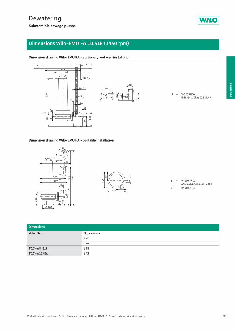
263
DewateringSubmersible sewage pumps
Dew
ater
ing
Dimensions Wilo-EMU FA 10.51E (1450 rpm)
Wilo Building Services catalogue – 50 Hz – Drainage and sewage – Edition 2011/2012 – Subject to change without prior notice
Dimension drawing Wilo-EMU FA - stationary wet well installation
Dimension drawing Wilo-EMU FA - portable installation
Dimensions
Wilo-EMU... DimensionsAW
mm
T 17-4/8 (Ex) 338
T 17-4/12 (Ex) 373
1 = DN100 PN10ANSI B16.1, Class 125, Size 4
85
438
115
325
65
1
225
90/ 96
176 15190
160DN 32 10990
310
50
110
44
AW
800
50
1 = DN100 PN10 ANSI B16.1, Class 125, Size 4
2 = DN100 PN10
1
200373
34517
8
Ø 280
126 23
843
948
8
120
587
100
323
418
666
180
2
553
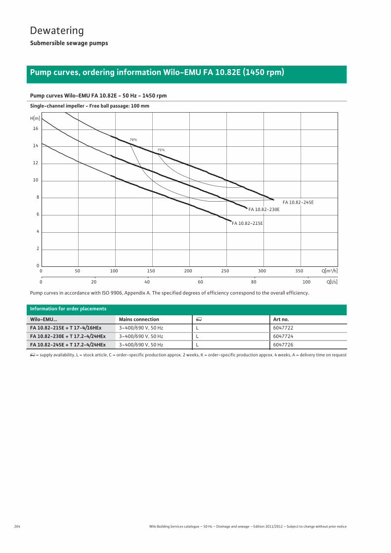
264 Wilo Building Services catalogue – 50 Hz – Drainage and sewage – Edition 2011/2012 – Subject to change without prior notice
DewateringSubmersible sewage pumps
Pump curves, ordering information Wilo-EMU FA 10.82E (1450 rpm)
Pump curves Wilo-EMU FA 10.82E - 50 Hz - 1450 rpm
Single-channel impeller - Free ball passage: 100 mm
Pump curves in accordance with ISO 9906, Appendix A. The specified degrees of efficiency correspond to the overall efficiency.
Information for order placements
Wilo-EMU... Mains connection � Art no.FA 10.82-215E + T 17-4/16HEx 3~400/690 V, 50 Hz L 6047722
FA 10.82-230E + T 17.2-4/24HEx 3~400/690 V, 50 Hz L 6047724
FA 10.82-245E + T 17.2-4/24HEx 3~400/690 V, 50 Hz L 6047726
�= supply availability, L = stock article, C = order-specific production approx. 2 weeks, K = order-specific production approx. 4 weeks, A = delivery time on request
70%
75%
FA 10.82-230E
FA 10.82-215E
FA 10.82-245E
Q[m³/h]0 50 100 150 200 250 300 350
Q[l/s]0 20 40 60 80 100
H[m]
0
2
4
6
8
10
12
14
16

265
DewateringSubmersible sewage pumps
Wilo Building Services catalogue – 50 Hz – Drainage and sewage – Edition 2011/2012 – Subject to change without prior notice
Technical data Wilo-EMU FA 10.82E (1450 rpm)
Dew
ater
ing
FA 10.82-215E + T 17-4/16HEx
FA 10.82-230E + T 17.2-4/24HEx
FA 10.82-245E + T 17.2-4/24HEx
3~400/690 V, 50 Hz 3~400/690 V, 50 Hz 3~400/690 V, 50 Hz
Unit
Pressure connection DN 100 DN 100 DN 100
Free ball passage mm 100 100 100
Max. volume flow Qmax / m3/h 260 288 314
Max. delivery head Hmax / m 14.3 17.2 20
Operating mode (immersed) S1 S1 S1
Operating mode (non-immersed) – – –
Max. immersion depth m 12.5 12.5 12.5
Protection class IP 68 IP 68 IP 68
Fluid temperature T / °C +3 ... +40 +3 ... +40 +3 ... +40
Weight approx. m / kg 117 147 148
Motor data
Nominal current IN / A 13.5 21 21
Starting current IA / A 68 123 123
Nominal motor power P2 / kW 6.5 10 10
Power consumption P1 / kW 8.2 12.2 12.2
Activation type Star-delta Star-delta Star-delta
Nominal speed n / rpm 1400 1417 1417
Insulation class F F F
Recommended switching frequency 1/h – – –
Max. switching frequency 1/h 15 15 15
Permitted voltage tolerance % +/- 10 +/- 10 +/- 10
Cable
Length of connecting cable m 10 10 10
Cable type H07RN-F H07RN-F H07RN-F
Cable cross-section mm2 10G1,5 10G1,5 10G1,5
Type of connecting cable Non-detachable Non-detachable Non-detachable
Mains plug – – –
Equipment/function
Float switch – – –
Motor protection WSK WSK WSK
Explosion protection ATEX ATEX ATEX
Materials
Static seal NBR NBR NBR
Impeller EN-GJL-250 EN-GJL-250 EN-GJL-250
Sealing on motor side NBR NBR NBR
Mechanical seal SiC/SiC SiC/SiC SiC/SiC
Motor housing EN-GJL-250 EN-GJL-250 EN-GJL-250
Pump housing EN-GJL-250 EN-GJL-250 EN-GJL-250
Pump shaft 1.4021 1.4021 1.4021
P1 refers to the maximum power consumption. All of the data applies to 3~400 V, 50 Hz and a density of 1 kg/dm3.
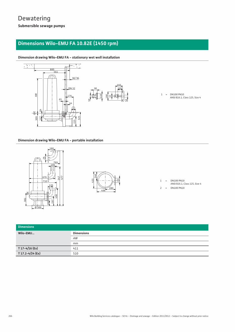
266 Wilo Building Services catalogue – 50 Hz – Drainage and sewage – Edition 2011/2012 – Subject to change without prior notice
DewateringSubmersible sewage pumps
Dimensions Wilo-EMU FA 10.82E (1450 rpm)
Dimension drawing Wilo-EMU FA - stationary wet well installation
Dimension drawing Wilo-EMU FA - portable installation
Dimensions
Wilo-EMU... DimensionsAW
mm
T 17-4/16 (Ex) 411
T 17.2-4/24 (Ex) 510
1 = DN100 PN10ANSI B16.1, Class 125, Size 4
84
561
117
325
65
1
225
90/ 96
176 15190
160DN 32 10990
309
50
110
44
AW
800
50
1 = DN100 PN10 ANSI B16.1, Class 125, Size 4
2 = DN100 PN10
1
280496
433240
Ø 500
180 297498
547
120
710
100
381
477
789
180
2
676
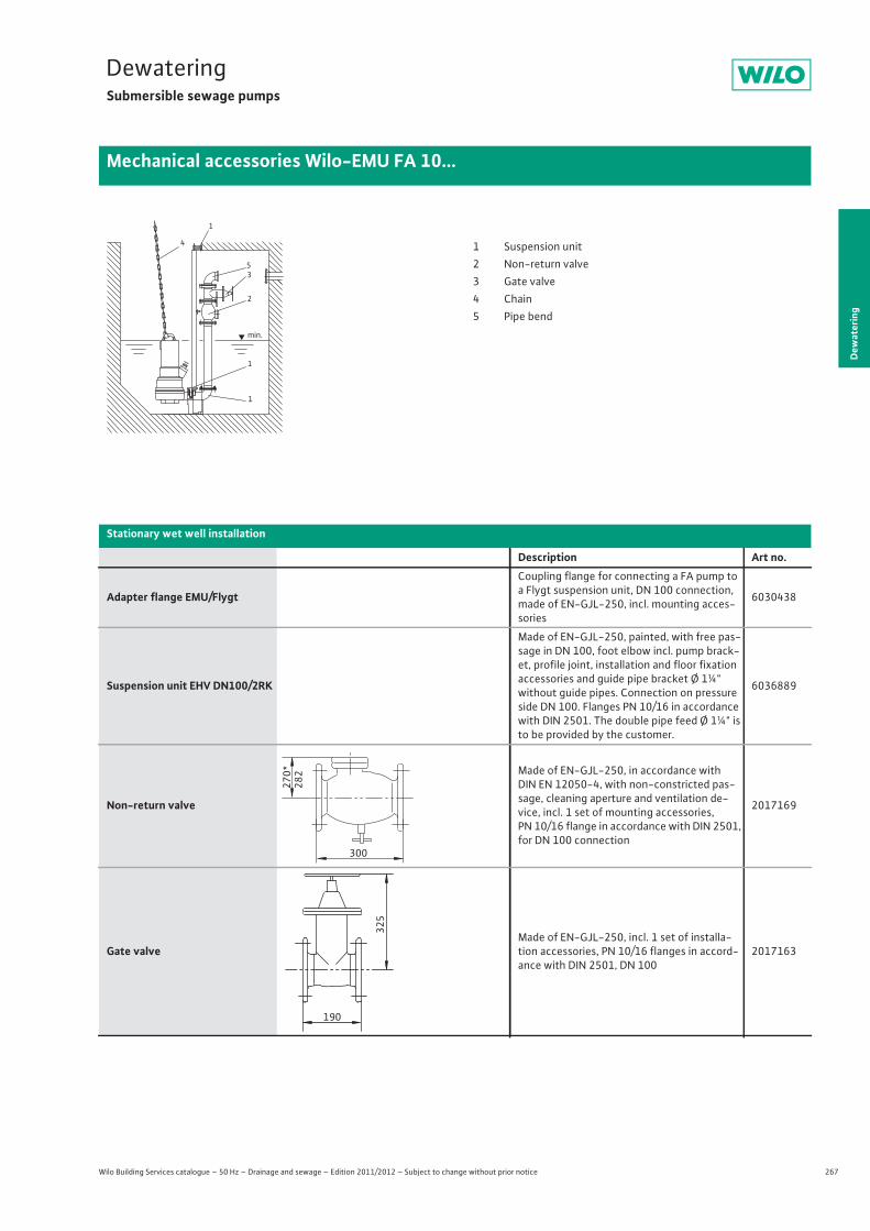
267
DewateringSubmersible sewage pumps
Dew
ater
ing
Mechanical accessories Wilo-EMU FA 10...
Wilo Building Services catalogue – 50 Hz – Drainage and sewage – Edition 2011/2012 – Subject to change without prior notice
Stationary wet well installation
Description Art no.
Adapter flange EMU/Flygt
Coupling flange for connecting a FA pump to a Flygt suspension unit, DN 100 connection, made of EN-GJL-250, incl. mounting acces-sories
6030438
Suspension unit EHV DN100/2RK
Made of EN-GJL-250, painted, with free pas-sage in DN 100, foot elbow incl. pump brack-et, profile joint, installation and floor fixation accessories and guide pipe bracket Ø 1¼" without guide pipes. Connection on pressure side DN 100. Flanges PN 10/16 in accordance with DIN 2501. The double pipe feed Ø 1¼" is to be provided by the customer.
6036889
Non-return valve
Made of EN-GJL-250, in accordance with DIN EN 12050-4, with non-constricted pas-sage, cleaning aperture and ventilation de-vice, incl. 1 set of mounting accessories, PN 10/16 flange in accordance with DIN 2501, for DN 100 connection
2017169
Gate valveMade of EN-GJL-250, incl. 1 set of installa-tion accessories, PN 10/16 flanges in accord-ance with DIN 2501, DN 100
2017163
1
4
53
2
1
1
min.
1 Suspension unit2 Non-return valve3 Gate valve4 Chain5 Pipe bend
270*
282
300
325
190
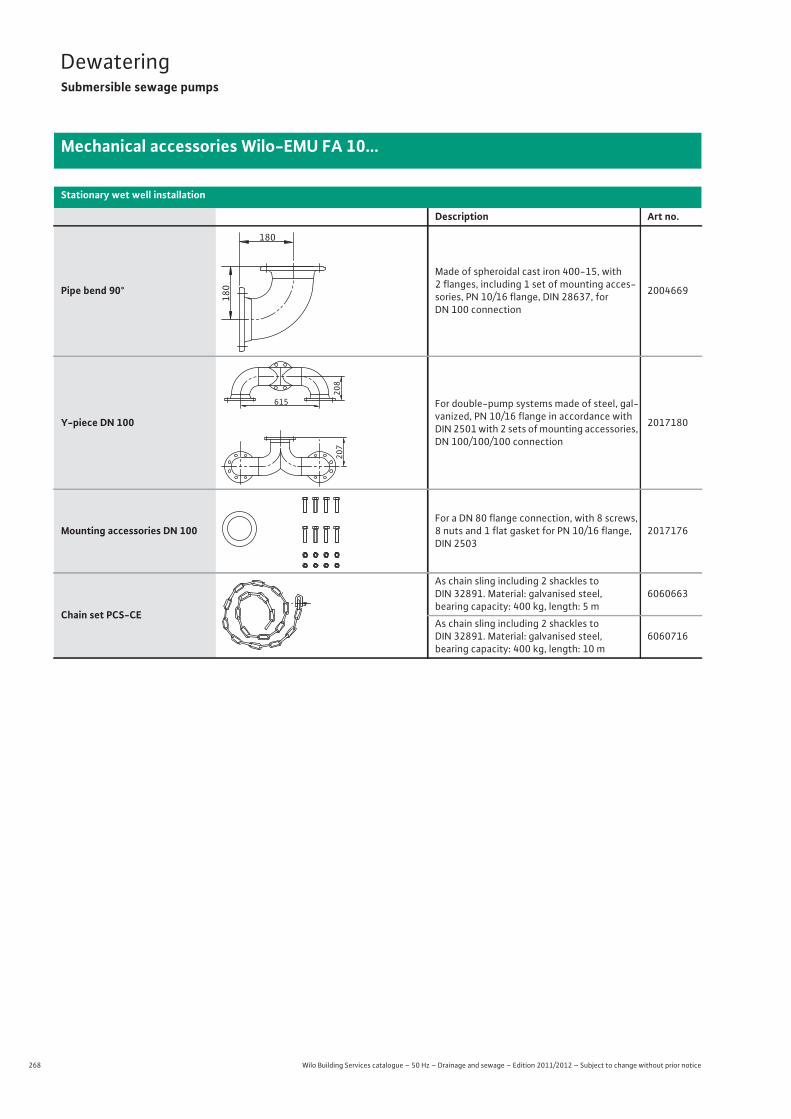
268 Wilo Building Services catalogue – 50 Hz – Drainage and sewage – Edition 2011/2012 – Subject to change without prior notice
DewateringSubmersible sewage pumps
Mechanical accessories Wilo-EMU FA 10...
Pipe bend 90°
Made of spheroidal cast iron 400-15, with2 flanges, including 1 set of mounting acces-sories, PN 10/16 flange, DIN 28637, forDN 100 connection
2004669
Y-piece DN 100
For double-pump systems made of steel, gal-vanized, PN 10/16 flange in accordance with DIN 2501 with 2 sets of mounting accessories, DN 100/100/100 connection
2017180
Mounting accessories DN 100For a DN 80 flange connection, with 8 screws, 8 nuts and 1 flat gasket for PN 10/16 flange, DIN 2503
2017176
Chain set PCS-CE
As chain sling including 2 shackles to DIN 32891. Material: galvanised steel, bearing capacity: 400 kg, length: 5 m
6060663
As chain sling including 2 shackles to DIN 32891. Material: galvanised steel, bearing capacity: 400 kg, length: 10 m
6060716
Stationary wet well installation
Description Art no.
180180
207
615
208
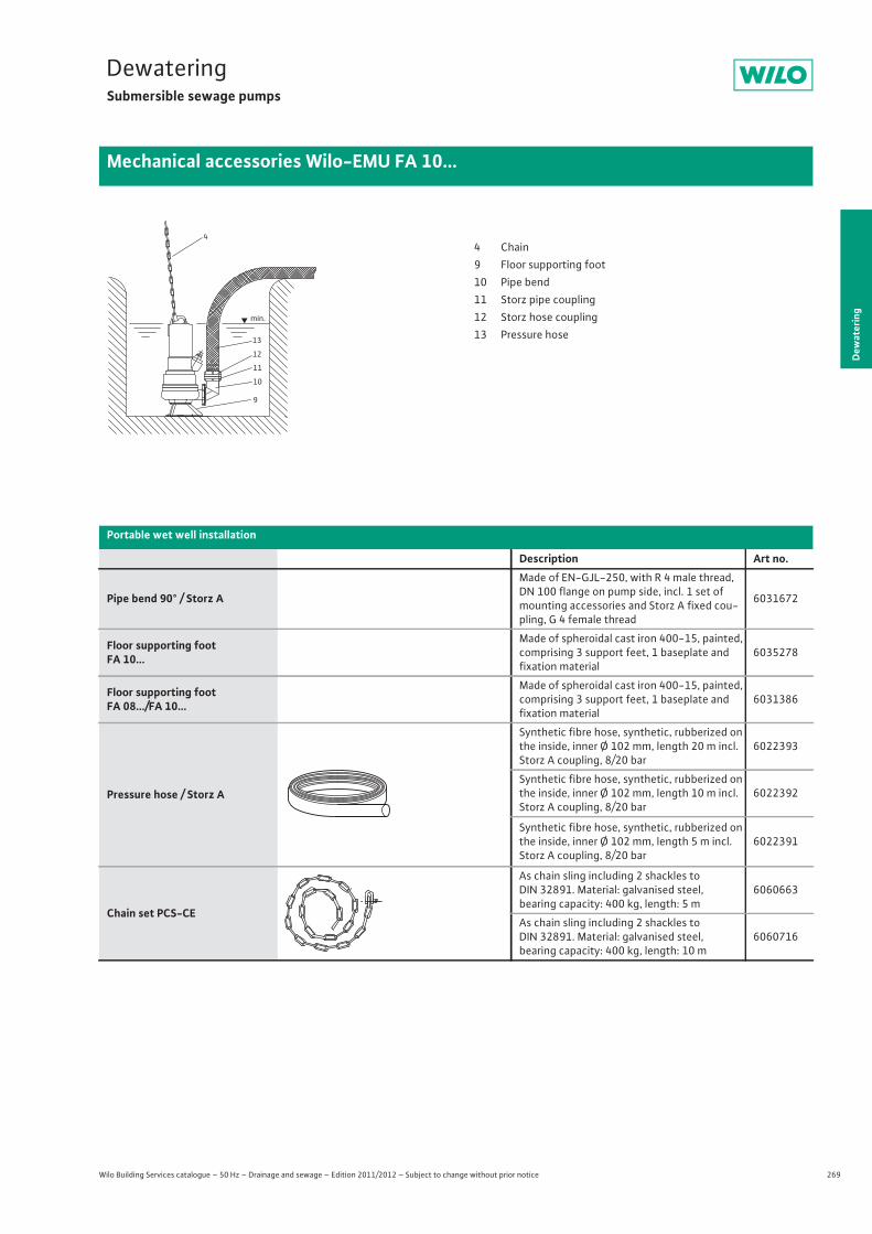
269
DewateringSubmersible sewage pumps
Dew
ater
ing
Mechanical accessories Wilo-EMU FA 10...
Wilo Building Services catalogue – 50 Hz – Drainage and sewage – Edition 2011/2012 – Subject to change without prior notice
Portable wet well installation
Description Art no.
Pipe bend 90° / Storz A
Made of EN-GJL-250, with R 4 male thread, DN 100 flange on pump side, incl. 1 set of mounting accessories and Storz A fixed cou-pling, G 4 female thread
6031672
Floor supporting footFA 10...
Made of spheroidal cast iron 400-15, painted, comprising 3 support feet, 1 baseplate and fixation material
6035278
Floor supporting footFA 08.../FA 10...
Made of spheroidal cast iron 400-15, painted, comprising 3 support feet, 1 baseplate and fixation material
6031386
Pressure hose / Storz A
Synthetic fibre hose, synthetic, rubberized on the inside, inner Ø 102 mm, length 20 m incl. Storz A coupling, 8/20 bar
6022393
Synthetic fibre hose, synthetic, rubberized on the inside, inner Ø 102 mm, length 10 m incl. Storz A coupling, 8/20 bar
6022392
Synthetic fibre hose, synthetic, rubberized on the inside, inner Ø 102 mm, length 5 m incl. Storz A coupling, 8/20 bar
6022391
Chain set PCS-CE
As chain sling including 2 shackles to DIN 32891. Material: galvanised steel, bearing capacity: 400 kg, length: 5 m
6060663
As chain sling including 2 shackles to DIN 32891. Material: galvanised steel, bearing capacity: 400 kg, length: 10 m
6060716
13
12
11
10
9
min.
44 Chain9 Floor supporting foot10 Pipe bend11 Storz pipe coupling12 Storz hose coupling13 Pressure hose
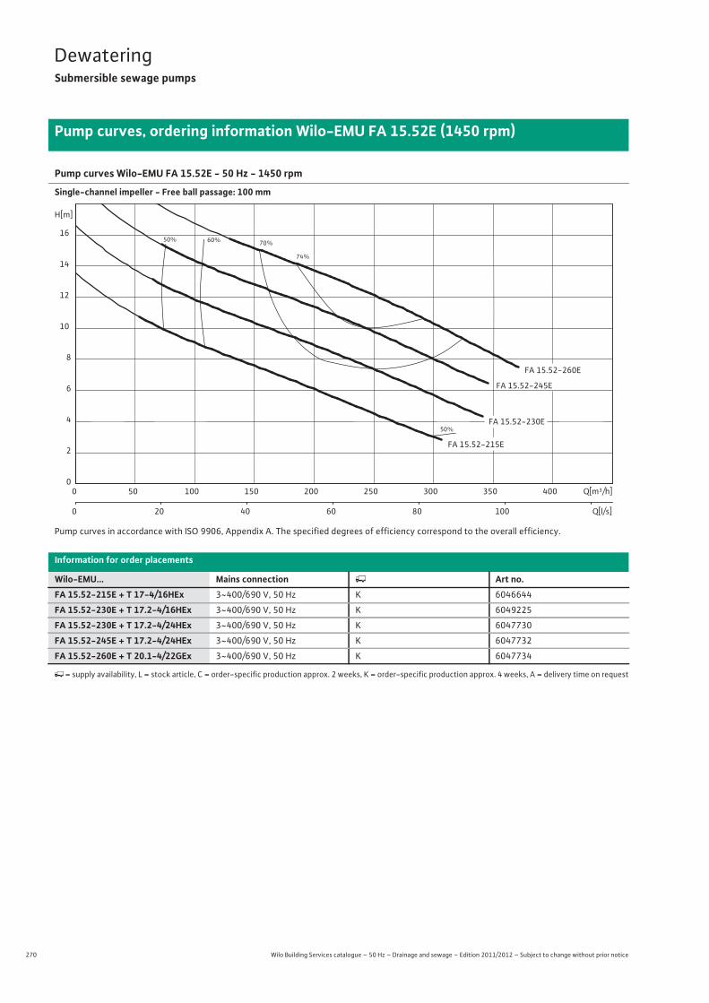
270 Wilo Building Services catalogue – 50 Hz – Drainage and sewage – Edition 2011/2012 – Subject to change without prior notice
DewateringSubmersible sewage pumps
Pump curves, ordering information Wilo-EMU FA 15.52E (1450 rpm)
Pump curves Wilo-EMU FA 15.52E - 50 Hz - 1450 rpm
Single-channel impeller - Free ball passage: 100 mm
Pump curves in accordance with ISO 9906, Appendix A. The specified degrees of efficiency correspond to the overall efficiency.
Information for order placements
Wilo-EMU... Mains connection � Art no.FA 15.52-215E + T 17-4/16HEx 3~400/690 V, 50 Hz K 6046644
FA 15.52-230E + T 17.2-4/16HEx 3~400/690 V, 50 Hz K 6049225
FA 15.52-230E + T 17.2-4/24HEx 3~400/690 V, 50 Hz K 6047730
FA 15.52-245E + T 17.2-4/24HEx 3~400/690 V, 50 Hz K 6047732
FA 15.52-260E + T 20.1-4/22GEx 3~400/690 V, 50 Hz K 6047734
�= supply availability, L = stock article, C = order-specific production approx. 2 weeks, K = order-specific production approx. 4 weeks, A = delivery time on request
50%
50%
60% 70%
74%
FA 15.52-260E
FA 15.52-230E
FA 15.52-245E
FA 15.52-215E
Q[m³/h]0 50 100 150 200 250 300 350 400
Q[l/s]0 20 40 60 80 100
H[m]
0
2
4
6
8
10
12
14
16

271
DewateringSubmersible sewage pumps
Wilo Building Services catalogue – 50 Hz – Drainage and sewage – Edition 2011/2012 – Subject to change without prior notice
Technical data Wilo-EMU FA 15.52E (1450 rpm)
Dew
ater
ing
FA 15.52-215E + T 17-4/16HEx
FA 15.52-230E + T 17.2-4/16HEx
FA 15.52-230E + T 17.2-4/24HEx
FA 15.52-245E + T 17.2-4/24HEx
FA 15.52-260E + T 20.1-4/22GEx
3~400/690 V, 50 Hz
3~400/690 V, 50 Hz
3~400/690 V, 50 Hz
3~400/690 V, 50 Hz
3~400/690 V, 50 Hz
Unit
Pressure connection DN 150 DN 150 DN 150 DN 150 DN 150
Free ball passage mm 100 100 100 100 100
Max. volume flow Qmax / m3/h 307 341 341 335 371
Max. delivery head Hmax / m 13.6 16.6 16.6 19.6 22.3
Operating mode (immersed) S1 S1 S1 S1 S1
Operating mode (non-immersed) – – – – S2-15 min.
Max. immersion depth m 12.5 12.5 12.5 12.5 12.5
Protection class IP 68 IP 68 IP 68 IP 68 IP 68
Fluid temperature T / °C +3 ... +40 +3 ... +40 +3 ... +40 +3 ... +40 +3 ... +40
Weight approx. m / kg 140 – 170 171 249
Motor data
Nominal current IN / A 13.5 13.5 21 21 30.5
Starting current IA / A 68 68 123 123 156
Nominal motor power P2 / kW 6.5 6.5 10 10 15
Power consumption P1 / kW 8.2 8.2 12.2 12.2 18.2
Activation type Star-delta Star-delta Star-delta Star-delta Star-delta
Nominal speed n / rpm 1400 1400 1417 1417 1425
Insulation class F F F F F
Recommended switching frequency 1/h – – – – –
Max. switching frequency 1/h 15 15 15 15 15
Permitted voltage tolerance % +/- 10 +/- 10 +/- 10 +/- 10 +/- 10
Cable
Length of connecting cable m 10 10 10 10 10
Cable type H07RN-F H07RN-F H07RN-F H07RN-F NSSHÖU
Cable cross-section mm2 10G1,5 10G1,5 10G1,5 10G1,5 7x2,5 + 7x1,5
Type of connecting cable Non-detachable Non-detachable Non-detachable Non-detachable Non-detachable
Mains plug – – – – –
Equipment/function
Float switch – – – – –
Motor protection WSK WSK WSK WSK WSK
Explosion protection ATEX ATEX ATEX ATEX ATEX
Materials
Static seal NBR NBR NBR NBR NBR
Impeller EN-GJL-250 EN-GJL-250 EN-GJL-250 EN-GJL-250 EN-GJL-250
Sealing on motor side NBR NBR NBR NBR C/Al-oxides
Mechanical seal SiC/SiC SiC/SiC SiC/SiC SiC/SiC SiC/SiC
Motor housing EN-GJL-250 EN-GJL-250 EN-GJL-250 EN-GJL-250 EN-GJL-250
Pump housing EN-GJL-250 EN-GJL-250 EN-GJL-250 EN-GJL-250 EN-GJL-250
Pump shaft 1.4021 1.4021 1.4021 1.4021 1.4021
P1 refers to the maximum power consumption. All of the data applies to 3~400 V, 50 Hz and a density of 1 kg/dm3.
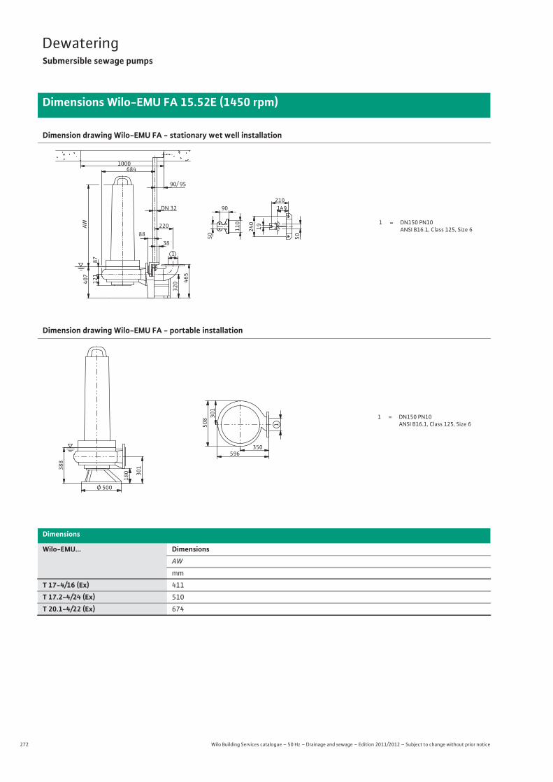
272 Wilo Building Services catalogue – 50 Hz – Drainage and sewage – Edition 2011/2012 – Subject to change without prior notice
DewateringSubmersible sewage pumps
Dimensions Wilo-EMU FA 15.52E (1450 rpm)
Dimension drawing Wilo-EMU FA - stationary wet well installation
Dimension drawing Wilo-EMU FA - portable installation
Dimensions
Wilo-EMU... DimensionsAW
mm
T 17-4/16 (Ex) 411
T 17.2-4/24 (Ex) 510
T 20.1-4/22 (Ex) 674
1 = DN150 PN10ANSI B16.1, Class 125, Size 6
87
684
121
465
88
1
320
90/ 95
220 19240
210DN 32 14990
407
50
110
38
AW
1000
50
1 = DN150 PN10ANSI B16.1, Class 125, Size 61
350596
508 30
1
Ø 500
180 301388
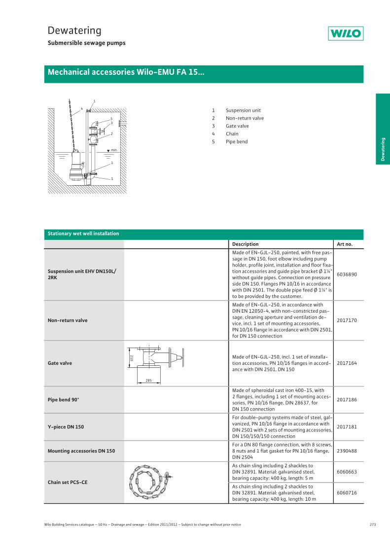
273
DewateringSubmersible sewage pumps
Dew
ater
ing
Mechanical accessories Wilo-EMU FA 15...
Wilo Building Services catalogue – 50 Hz – Drainage and sewage – Edition 2011/2012 – Subject to change without prior notice
1
4
53
2
1
1
min.
1 Suspension unit2 Non-return valve3 Gate valve4 Chain5 Pipe bend
Stationary wet well installation
Description Art no.
Suspension unit EHV DN150L/2RK
Made of EN-GJL-250, painted, with free pas-sage in DN 150, foot elbow including pump holder, profile joint, installation and floor fixa-tion accessories and guide pipe bracket Ø 1¼" without guide pipes. Connection on pressure side DN 150. Flanges PN 10/16 in accordance with DIN 2501. The double pipe feed Ø 1¼" is to be provided by the customer.
6036890
Non-return valve
Made of EN-GJL-250, in accordance with DIN EN 12050-4, with non-constricted pas-sage, cleaning aperture and ventilation de-vice, incl. 1 set of mounting accessories, PN 10/16 flange in accordance with DIN 2501, for DN 150 connection
2017170
Gate valveMade of EN-GJL-250, incl. 1 set of installa-tion accessories, PN 10/16 flanges in accord-ance with DIN 2501, DN 150
2017164
Pipe bend 90°
Made of spheroidal cast iron 400-15, with2 flanges, including 1 set of mounting acces-sories, PN 10/16 flange, DIN 28637, forDN 150 connection
2017186
Y-piece DN 150
For double-pump systems made of steel, gal-vanized, PN 10/16 flange in accordance with DIN 2501 with 2 sets of mounting accessories, DN 150/150/150 connection
2017181
Mounting accessories DN 150For a DN 80 flange connection, with 8 screws, 8 nuts and 1 flat gasket for PN 10/16 flange, DIN 2504
2390488
Chain set PCS-CE
As chain sling including 2 shackles to DIN 32891. Material: galvanised steel, bearing capacity: 400 kg, length: 5 m
6060663
As chain sling including 2 shackles to DIN 32891. Material: galvanised steel, bearing capacity: 400 kg, length: 10 m
6060716
210
285
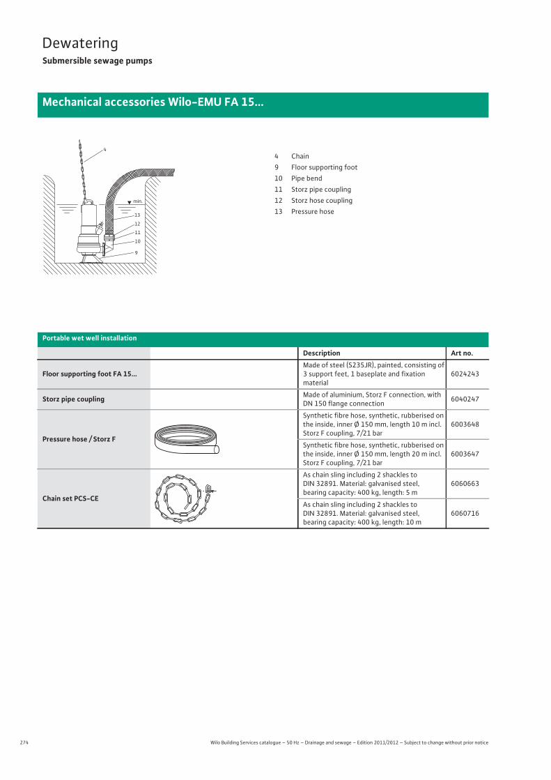
274 Wilo Building Services catalogue – 50 Hz – Drainage and sewage – Edition 2011/2012 – Subject to change without prior notice
DewateringSubmersible sewage pumps
Mechanical accessories Wilo-EMU FA 15...
Portable wet well installation
Description Art no.
Floor supporting foot FA 15...Made of steel (S235JR), painted, consisting of 3 support feet, 1 baseplate and fixationmaterial
6024243
Storz pipe coupling Made of aluminium, Storz F connection, with DN 150 flange connection 6040247
Pressure hose / Storz F
Synthetic fibre hose, synthetic, rubberised on the inside, inner Ø 150 mm, length 10 m incl. Storz F coupling, 7/21 bar
6003648
Synthetic fibre hose, synthetic, rubberised on the inside, inner Ø 150 mm, length 20 m incl. Storz F coupling, 7/21 bar
6003647
Chain set PCS-CE
As chain sling including 2 shackles to DIN 32891. Material: galvanised steel, bearing capacity: 400 kg, length: 5 m
6060663
As chain sling including 2 shackles to DIN 32891. Material: galvanised steel, bearing capacity: 400 kg, length: 10 m
6060716
13
12
11
10
9
min.
44 Chain9 Floor supporting foot10 Pipe bend11 Storz pipe coupling12 Storz hose coupling13 Pressure hose
275
DewateringSubmersible sewage pumps
Dew
ater
ing
Mechanical accessories Wilo-EMU FA 15...
Wilo Building Services catalogue – 50 Hz – Drainage and sewage – Edition 2011/2012 – Subject to change without prior notice
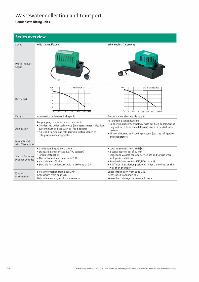
276 Wilo Building Services catalogue – 50 Hz – Drainage and sewage – Edition 2011/2012 – Subject to change without prior notice
Wastewater collection and transportCondensate lifting units
Series overview
Series Wilo-DrainLift Con Wilo-DrainLift Con Plus
Photo Product Group
Duty chart
Design Automatic condensate lifting unit Automatic condensate lifting unit
Application
For pumping condensate, can be used in• Condensing boiler technology (an upstream neutralisation
system must be used with oil-fired boilers)• Air-conditioning and refrigeration systems (such as
refrigerators and evaporators)
For pumping condensate in:• Condensing boiler technology (with oil-fired boilers, the lif-
ting unit must be installed downstream of a neutralisation system)
• Air-conditioning and cooling systems (such as refrigerators and evaporators)
Max. intake/h with S3 operation – –
Special features/product benefits
• 2 inlet openings Ø 19-30 mm• Standard alarm contact (NC/NO contact)• Simple installation• The motor unit can be rotated 180°.• Variable inlets/drains• Suitable for condensates with a pH value of 2.4
• Low-noise operation (45dB[A])• 4 condensate feeds Ø 30 mm• Large tank volume for long service life and for use with
multiple installations• Standard alarm contact (NC/NO contact)• 3 different installation positions: under the ceiling, on the
wall or on the floor
Furtherinformation
Series information from page 279Accessories from page 282Wilo online catalogue at www.wilo.com
Series information from page 283Accessories from page 286Wilo online catalogue at www.wilo.com
Q/l/h60048036024012000
1
2
3
4
5
6Wilo-DrainLift ConH/m
Q/l/h420240 300 360180120600
Wilo-DrainLift Con Plus
0
1
2
3
4
5
H/m
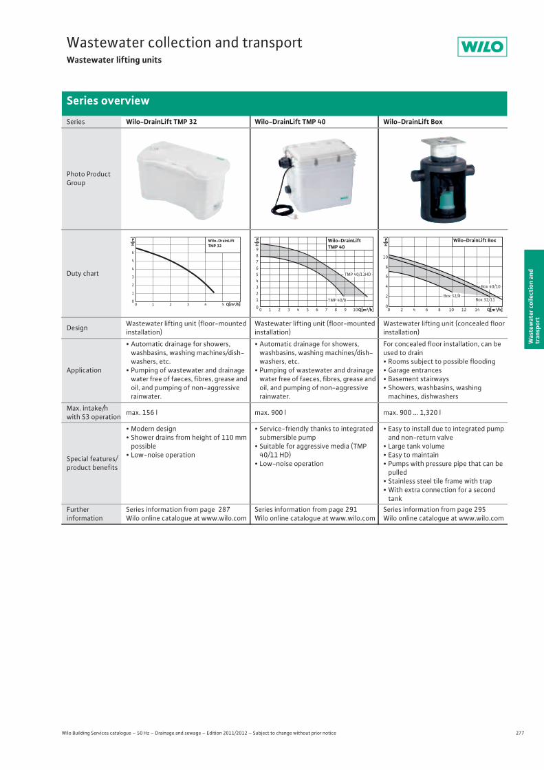
277
Wastewater collection and transportWastewater lifting units
Wilo Building Services catalogue – 50 Hz – Drainage and sewage – Edition 2011/2012 – Subject to change without prior notice
Series overview
Was
tew
ater
col
lect
ion
and
tran
spor
t
Series Wilo-DrainLift TMP 32 Wilo-DrainLift TMP 40 Wilo-DrainLift Box
Photo Product Group
Duty chart
Design Wastewater lifting unit (floor-mounted installation)
Wastewater lifting unit (floor-mounted installation)
Wastewater lifting unit (concealed floor installation)
Application
• Automatic drainage for showers, washbasins, washing machines/dish-washers, etc.
• Pumping of wastewater and drainage water free of faeces, fibres, grease and oil, and pumping of non-aggressive rainwater.
• Automatic drainage for showers, washbasins, washing machines/dish-washers, etc.
• Pumping of wastewater and drainage water free of faeces, fibres, grease and oil, and pumping of non-aggressive rainwater.
For concealed floor installation, can be used to drain• Rooms subject to possible flooding• Garage entrances• Basement stairways• Showers, washbasins, washing
machines, dishwashers
Max. intake/h with S3 operation max. 156 l max. 900 l max. 900 ... 1,320 l
Special features/product benefits
• Modern design• Shower drains from height of 110 mm
possible• Low-noise operation
• Service-friendly thanks to integrated submersible pump
• Suitable for aggressive media (TMP 40/11 HD)
• Low-noise operation
• Easy to install due to integrated pump and non-return valve
• Large tank volume• Easy to maintain• Pumps with pressure pipe that can be
pulled• Stainless steel tile frame with trap• With extra connection for a second
tankFurtherinformation
Series information from page 287Wilo online catalogue at www.wilo.com
Series information from page 291 Wilo online catalogue at www.wilo.com
Series information from page 295 Wilo online catalogue at www.wilo.com
Wilo-DrainLiftTMP 32
2
3
0
5
6
4
1
H[m]
0 4 52 31 Q[m³/h]
Wilo-DrainLiftTMP 40
23
0
56789
4
1
H[m]
0 4 5 8 92 31 6 7 10Q[m³/h]
TMP 40/8
TMP 40/11HD
0
2
4
6
8
10
H[m]
0 2 4 6 8 10 12 14 Q[m³/h]
Box 32/8
Box 40/10
Box 32/11
Wilo-DrainLift Box
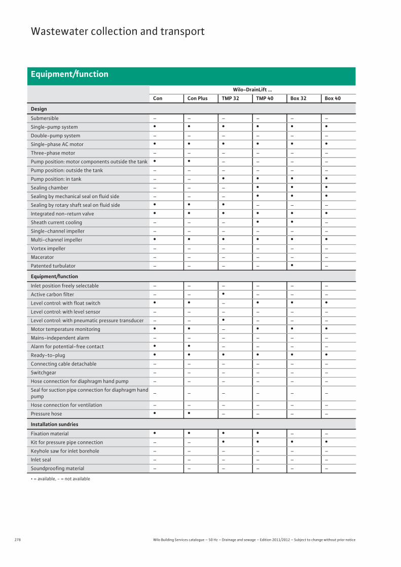
278 Wilo Building Services catalogue – 50 Hz – Drainage and sewage – Edition 2011/2012 – Subject to change without prior notice
Wastewater collection and transport
Equipment/function
Wilo-DrainLift ...Con Con Plus TMP 32 TMP 40 Box 32 Box 40
Design
Submersible – – – – – –
Single-pump system • • • • • •Double-pump system – – – – – –
Single-phase AC motor • • • • • •Three-phase motor – – – – – –
Pump position: motor components outside the tank • • – – – –
Pump position: outside the tank – – – – – –
Pump position: in tank – – • • • •Sealing chamber – – – • • •Sealing by mechanical seal on fluid side – – – • • •Sealing by rotary shaft seal on fluid side • • • – – –
Integrated non-return valve • • • • • •Sheath current cooling – – – • • –
Single-channel impeller – – – – – –
Multi-channel impeller • • • • • •Vortex impeller – – – – – –
Macerator – – – – – –
Patented turbulator – – – – • –
Equipment/function
Inlet position freely selectable – – – – – –
Active carbon filter – – • – – –
Level control: with float switch • • – • • •Level control: with level sensor – – – – – –
Level control: with pneumatic pressure transducer – – • – – –
Motor temperature monitoring • • – • • •Mains-independent alarm – – – – – –
Alarm for potential-free contact • • – – – –
Ready-to-plug • • • • • •Connecting cable detachable – – – – – –
Switchgear – – – – – –
Hose connection for diaphragm hand pump – – – – – –
Seal for suction pipe connection for diaphragm hand pump – – – – – –
Hose connection for ventilation – – – – – –
Pressure hose • • – – – –
Installation sundries
Fixation material • • • • – –
Kit for pressure pipe connection – – • • • •Keyhole saw for inlet borehole – – – – – –
Inlet seal – – – – – –
Soundproofing material – – – – – –
• = available, - = not available
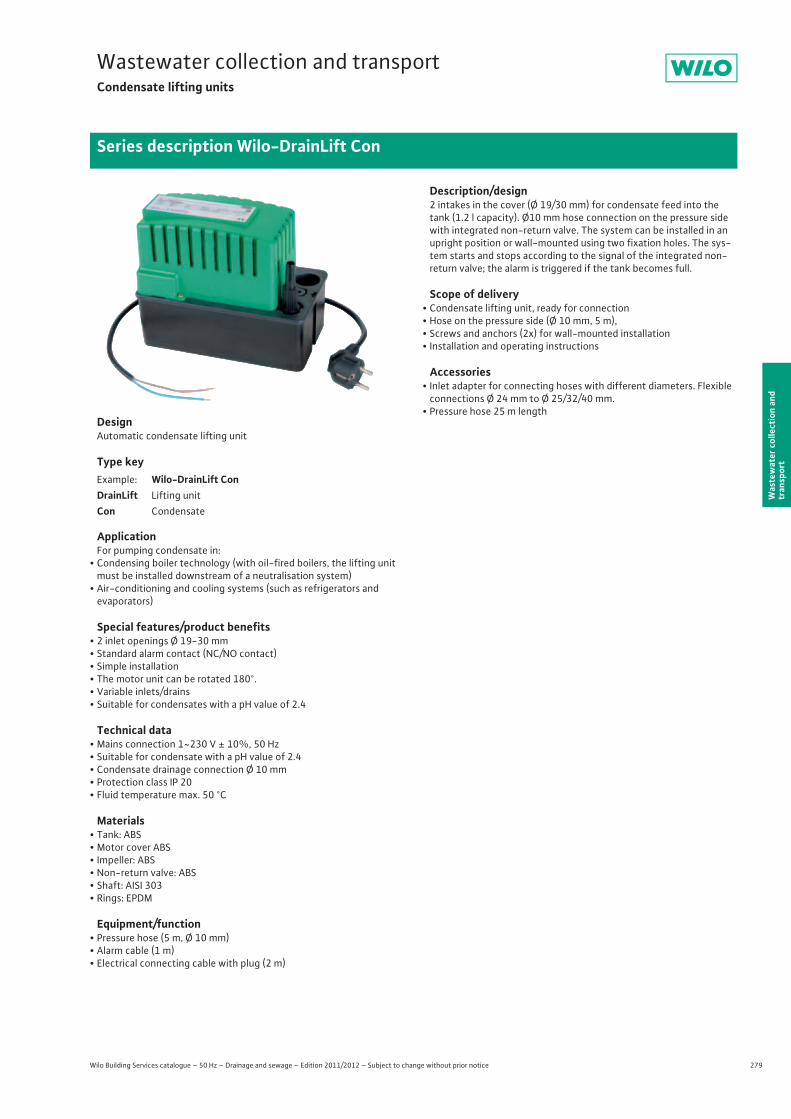
279
Wastewater collection and transportCondensate lifting units
Wilo Building Services catalogue – 50 Hz – Drainage and sewage – Edition 2011/2012 – Subject to change without prior notice
Series description Wilo-DrainLift Con
Was
tew
ater
col
lect
ion
and
tran
spor
t
DesignAutomatic condensate lifting unit
Type key
ApplicationFor pumping condensate in:
• Condensing boiler technology (with oil-fired boilers, the lifting unit must be installed downstream of a neutralisation system)
• Air-conditioning and cooling systems (such as refrigerators and evaporators)
Special features/product benefits• 2 inlet openings Ø 19-30 mm• Standard alarm contact (NC/NO contact)• Simple installation• The motor unit can be rotated 180°.• Variable inlets/drains• Suitable for condensates with a pH value of 2.4
Technical data• Mains connection 1~230 V ± 10%, 50 Hz• Suitable for condensate with a pH value of 2.4• Condensate drainage connection Ø 10 mm• Protection class IP 20• Fluid temperature max. 50 °C
Materials• Tank: ABS• Motor cover ABS• Impeller: ABS• Non-return valve: ABS• Shaft: AISI 303• Rings: EPDM
Equipment/function• Pressure hose (5 m, Ø 10 mm)• Alarm cable (1 m)• Electrical connecting cable with plug (2 m)
Description/design2 intakes in the cover (Ø 19/30 mm) for condensate feed into the tank (1.2 l capacity). Ø10 mm hose connection on the pressure side with integrated non-return valve. The system can be installed in an upright position or wall-mounted using two fixation holes. The sys-tem starts and stops according to the signal of the integrated non-return valve; the alarm is triggered if the tank becomes full.
Scope of delivery• Condensate lifting unit, ready for connection• Hose on the pressure side (Ø 10 mm, 5 m),• Screws and anchors (2x) for wall-mounted installation• Installation and operating instructions
Accessories• Inlet adapter for connecting hoses with different diameters. Flexible
connections Ø 24 mm to Ø 25/32/40 mm.• Pressure hose 25 m length
Example: Wilo-DrainLift ConDrainLift Lifting unitCon Condensate
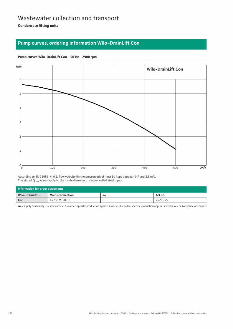
280 Wilo Building Services catalogue – 50 Hz – Drainage and sewage – Edition 2011/2012 – Subject to change without prior notice
Wastewater collection and transportCondensate lifting units
Pump curves, ordering information Wilo-DrainLift Con
Pump curves Wilo-DrainLift Con - 50 Hz - 2900 rpm
According to EN 12056-4, 6.1, flow velocity (in the pressure pipe) must be kept between 0.7 and 2.3 m/s.The stated Qmin values apply to the inside diameter of single-walled steel pipes.
Information for order placements
Wilo-DrainLift ... Mains connection � Art no.Con 1~230 V, 50 Hz L 2528555
�= supply availability, L = stock article, C = order-specific production approx. 2 weeks, K = order-specific production approx. 4 weeks, A = delivery time on request
00
1
2
3
4
5
6
120 240 360 480 600
Wilo-DrainLift Con
Q/l/h
H/m
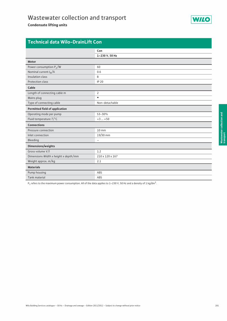
281
Wastewater collection and transportCondensate lifting units
Wilo Building Services catalogue – 50 Hz – Drainage and sewage – Edition 2011/2012 – Subject to change without prior notice
Technical data Wilo-DrainLift Con
Was
tew
ater
col
lect
ion
and
tran
spor
t
Con1~230 V, 50 Hz
Motor
Power consumption P1 / W 60
Nominal current IN / A 0.6
Insulation class B
Protection class IP 20
Cable
Length of connecting cable m 2
Mains plug •Type of connecting cable Non-detachable
Permitted field of application
Operating mode per pump S3-30%
Fluid temperature T / °C +3 ... +50
Connections
Pressure connection 10 mm
Inlet connection 19/30 mm
Bleeding –
Dimensions/weights
Gross volume V / l 1.2
Dimensions Width x height x depth / mm 210 x 120 x 167
Weight approx. m / kg 2.1
Materials
Pump housing ABS
Tank material ABS
P1 refers to the maximum power consumption. All of the data applies to 1~230 V, 50 Hz and a density of 1 kg/dm3.
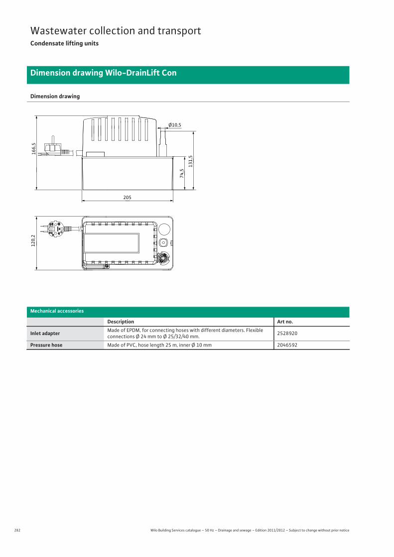
282 Wilo Building Services catalogue – 50 Hz – Drainage and sewage – Edition 2011/2012 – Subject to change without prior notice
Wastewater collection and transportCondensate lifting units
Dimension drawing Wilo-DrainLift Con
Dimension drawing
Mechanical accessories
Description Art no.
Inlet adapter Made of EPDM, for connecting hoses with different diameters. Flexible connections Ø 24 mm to Ø 25/32/40 mm. 2528920
Pressure hose Made of PVC, hose length 25 m, inner Ø 10 mm 2046592
166,5
Ø10,5
120,2
131,5
205
74,5
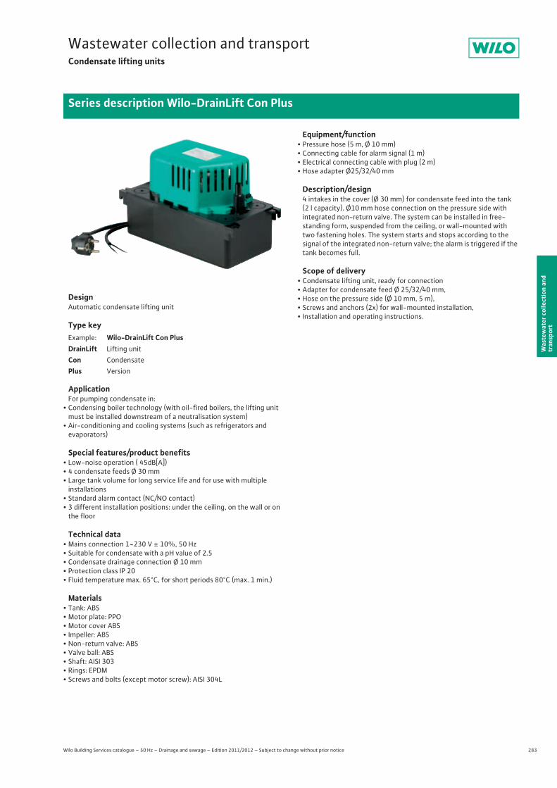
283
Wastewater collection and transportCondensate lifting units
Wilo Building Services catalogue – 50 Hz – Drainage and sewage – Edition 2011/2012 – Subject to change without prior notice
Series description Wilo-DrainLift Con Plus
Was
tew
ater
col
lect
ion
and
tran
spor
t
DesignAutomatic condensate lifting unit
Type key
ApplicationFor pumping condensate in:
• Condensing boiler technology (with oil-fired boilers, the lifting unit must be installed downstream of a neutralisation system)
• Air-conditioning and cooling systems (such as refrigerators and evaporators)
Special features/product benefits• Low-noise operation ( 45dB[A])• 4 condensate feeds Ø 30 mm• Large tank volume for long service life and for use with multiple
installations• Standard alarm contact (NC/NO contact)• 3 different installation positions: under the ceiling, on the wall or on
the floor
Technical data• Mains connection 1~230 V ± 10%, 50 Hz• Suitable for condensate with a pH value of 2.5• Condensate drainage connection Ø 10 mm• Protection class IP 20• Fluid temperature max. 65°C, for short periods 80°C (max. 1 min.)
Materials• Tank: ABS• Motor plate: PPO• Motor cover ABS• Impeller: ABS• Non-return valve: ABS• Valve ball: ABS• Shaft: AISI 303• Rings: EPDM• Screws and bolts (except motor screw): AISI 304L
Equipment/function• Pressure hose (5 m, Ø 10 mm)• Connecting cable for alarm signal (1 m)• Electrical connecting cable with plug (2 m)• Hose adapter Ø25/32/40 mm
Description/design4 intakes in the cover (Ø 30 mm) for condensate feed into the tank(2 l capacity). Ø10 mm hose connection on the pressure side withintegrated non-return valve. The system can be installed in free-standing form, suspended from the ceiling, or wall-mounted with two fastening holes. The system starts and stops according to the signal of the integrated non-return valve; the alarm is triggered if the tank becomes full.
Scope of delivery• Condensate lifting unit, ready for connection• Adapter for condensate feed Ø 25/32/40 mm,• Hose on the pressure side (Ø 10 mm, 5 m),• Screws and anchors (2x) for wall-mounted installation,• Installation and operating instructions.
Example: Wilo-DrainLift Con PlusDrainLift Lifting unitCon CondensatePlus Version
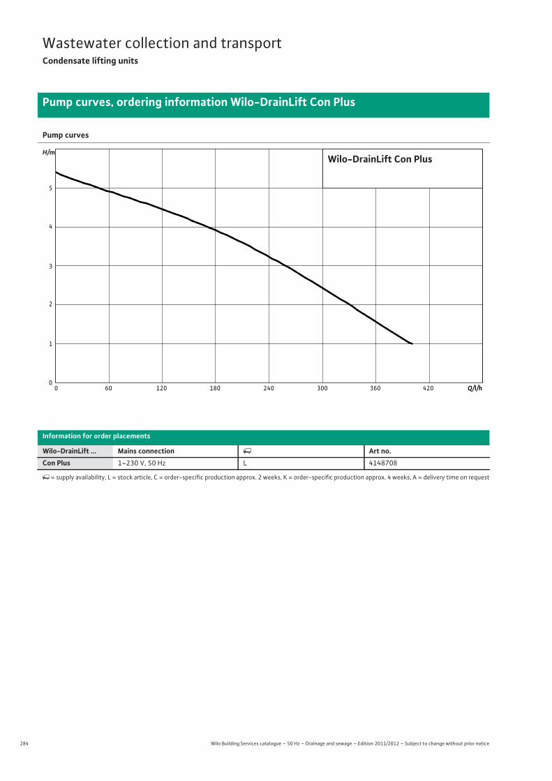
284 Wilo Building Services catalogue – 50 Hz – Drainage and sewage – Edition 2011/2012 – Subject to change without prior notice
Wastewater collection and transportCondensate lifting units
Pump curves, ordering information Wilo-DrainLift Con Plus
Pump curves
Information for order placements
Wilo-DrainLift ... Mains connection � Art no.Con Plus 1~230 V, 50 Hz L 4148708
�= supply availability, L = stock article, C = order-specific production approx. 2 weeks, K = order-specific production approx. 4 weeks, A = delivery time on request
Q/l/h420240 300 360180120600
Wilo-DrainLift Con Plus
0
1
2
3
4
5
H/m

285
Wastewater collection and transportCondensate lifting units
Wilo Building Services catalogue – 50 Hz – Drainage and sewage – Edition 2011/2012 – Subject to change without prior notice
Technical data Wilo-DrainLift Con Plus
Was
tew
ater
col
lect
ion
and
tran
spor
t
Con Plus1~230 V, 50 Hz
Motor
Power consumption P1 / W 70
Nominal current IN / A 0.7
Insulation class B
Protection class IP 20
Cable
Length of connecting cable m 2
Mains plug •Type of connecting cable Non-detachable
Permitted field of application
Operating mode per pump S3-30%
Fluid temperature T / °C +3 ... +80
Connections
Pressure connection 10 mm
Inlet connection 4x �30 mm
Bleeding –
Dimensions/weights
Gross volume V / l 2
Dimensions Width x height x depth / mm 195 x 170 x 130
Weight approx. m / kg 1.9
Materials
Pump housing ABS
Tank material ABS
• = available, - = not available
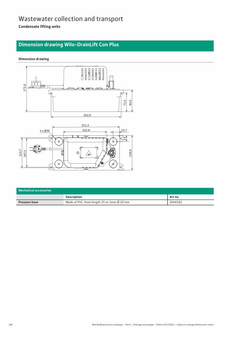
286 Wilo Building Services catalogue – 50 Hz – Drainage and sewage – Edition 2011/2012 – Subject to change without prior notice
Wastewater collection and transportCondensate lifting units
Dimension drawing Wilo-DrainLift Con Plus
Dimension drawing
Mechanical accessories
Description Art no.Pressure hose Made of PVC, hose length 25 m, inner Ø 10 mm 2046592
162,8
251,3
113,
7
23
23,7130,0
107,5
71,4
84,5
262,0
171,0
4 x Ø30
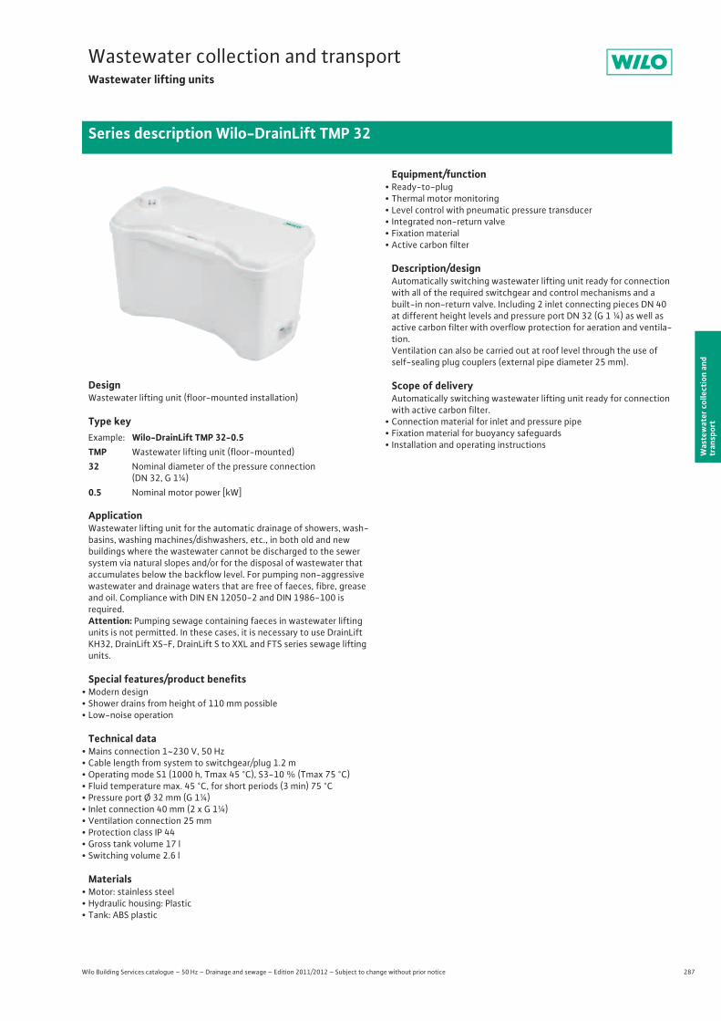
287
Wastewater collection and transportWastewater lifting units
Wilo Building Services catalogue – 50 Hz – Drainage and sewage – Edition 2011/2012 – Subject to change without prior notice
Series description Wilo-DrainLift TMP 32
Was
tew
ater
col
lect
ion
and
tran
spor
t
DesignWastewater lifting unit (floor-mounted installation)
Type key
ApplicationWastewater lifting unit for the automatic drainage of showers, wash-basins, washing machines/dishwashers, etc., in both old and new buildings where the wastewater cannot be discharged to the sewer system via natural slopes and/or for the disposal of wastewater that accumulates below the backflow level. For pumping non-aggressive wastewater and drainage waters that are free of faeces, fibre, grease and oil. Compliance with DIN EN 12050-2 and DIN 1986-100 isrequired.Attention: Pumping sewage containing faeces in wastewater lifting units is not permitted. In these cases, it is necessary to use DrainLift KH32, DrainLift XS-F, DrainLift S to XXL and FTS series sewage lifting units.
Special features/product benefits• Modern design• Shower drains from height of 110 mm possible• Low-noise operation
Technical data• Mains connection 1~230 V, 50 Hz• Cable length from system to switchgear/plug 1.2 m• Operating mode S1 (1000 h, Tmax 45 °C), S3-10 % (Tmax 75 °C) • Fluid temperature max. 45 °C, for short periods (3 min) 75 °C• Pressure port Ø 32 mm (G 1¼)• Inlet connection 40 mm (2 x G 1¼)• Ventilation connection 25 mm• Protection class IP 44• Gross tank volume 17 l• Switching volume 2.6 l
Materials• Motor: stainless steel• Hydraulic housing: Plastic• Tank: ABS plastic
Equipment/function• Ready-to-plug• Thermal motor monitoring• Level control with pneumatic pressure transducer• Integrated non-return valve• Fixation material• Active carbon filter
Description/designAutomatically switching wastewater lifting unit ready for connection with all of the required switchgear and control mechanisms and a built-in non-return valve. Including 2 inlet connecting pieces DN 40 at different height levels and pressure port DN 32 (G 1 ¼) as well as active carbon filter with overflow protection for aeration and ventila-tion.Ventilation can also be carried out at roof level through the use of self-sealing plug couplers (external pipe diameter 25 mm).
Scope of deliveryAutomatically switching wastewater lifting unit ready for connection with active carbon filter.
• Connection material for inlet and pressure pipe• Fixation material for buoyancy safeguards• Installation and operating instructions
Example: Wilo-DrainLift TMP 32-0.5TMP Wastewater lifting unit (floor-mounted)32 Nominal diameter of the pressure connection
(DN 32, G 1¼)0.5 Nominal motor power [kW]
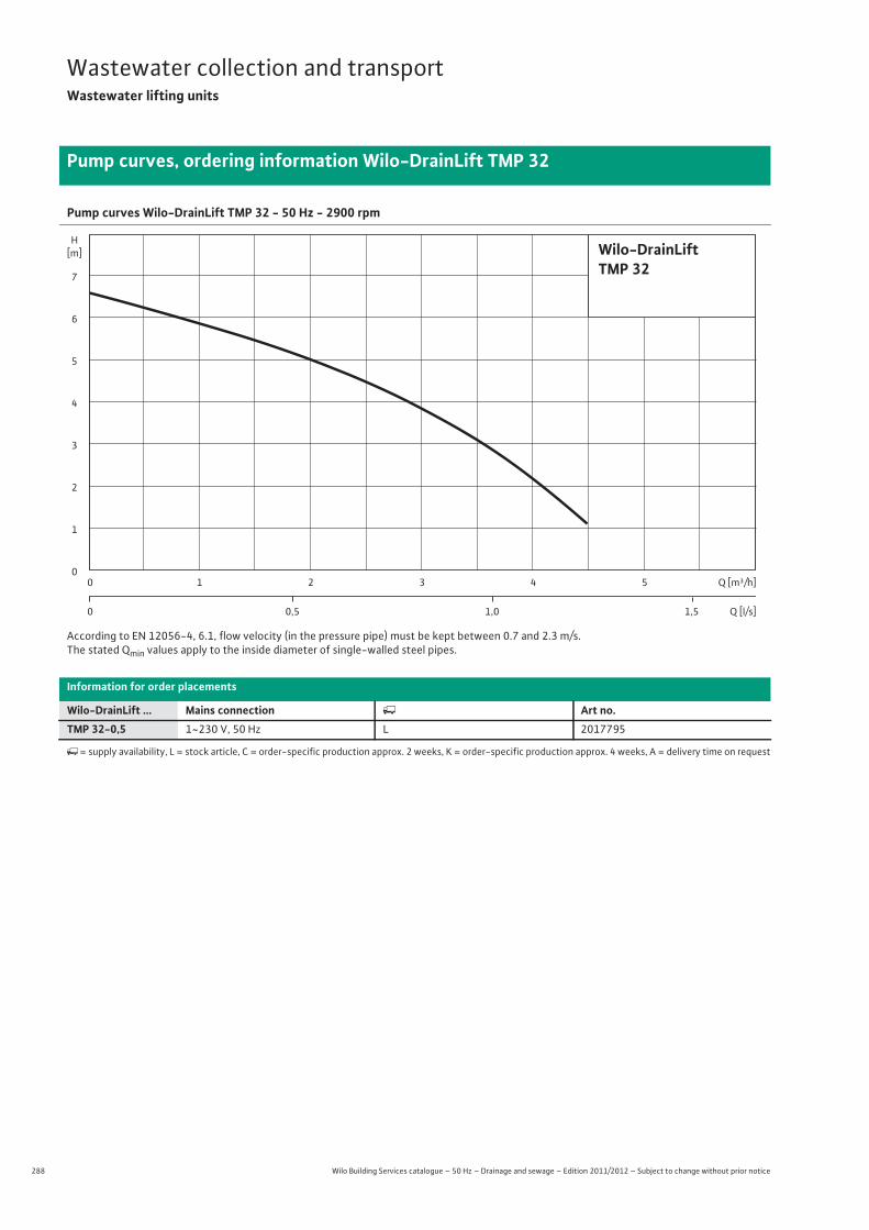
288 Wilo Building Services catalogue – 50 Hz – Drainage and sewage – Edition 2011/2012 – Subject to change without prior notice
Wastewater collection and transportWastewater lifting units
Pump curves, ordering information Wilo-DrainLift TMP 32
Pump curves Wilo-DrainLift TMP 32 - 50 Hz - 2900 rpm
According to EN 12056-4, 6.1, flow velocity (in the pressure pipe) must be kept between 0.7 and 2.3 m/s.The stated Qmin values apply to the inside diameter of single-walled steel pipes.
Information for order placements
Wilo-DrainLift ... Mains connection � Art no.TMP 32-0,5 1~230 V, 50 Hz L 2017795
�= supply availability, L = stock article, C = order-specific production approx. 2 weeks, K = order-specific production approx. 4 weeks, A = delivery time on request
Wilo-DrainLiftTMP 32
2
3
0
5
6
7
4
1
H[m]
0 4 52 31
0 1,00,5 1,5
Q [m³/h]
Q [l/s]
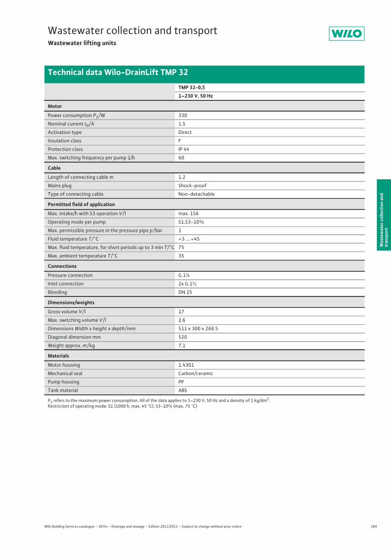
289
Wastewater collection and transportWastewater lifting units
Wilo Building Services catalogue – 50 Hz – Drainage and sewage – Edition 2011/2012 – Subject to change without prior notice
Technical data Wilo-DrainLift TMP 32
Was
tew
ater
col
lect
ion
and
tran
spor
t
TMP 32-0,51~230 V, 50 Hz
Motor
Power consumption P1 / W 330
Nominal current IN / A 1.5
Activation type Direct
Insulation class F
Protection class IP 44
Max. switching frequency per pump 1/h 60
Cable
Length of connecting cable m 1.2
Mains plug Shock-proof
Type of connecting cable Non-detachable
Permitted field of application
Max. intake/h with S3 operation V / l max. 156
Operating mode per pump S1,S3-10%
Max. permissible pressure in the pressure pipe p / bar 1
Fluid temperature T / °C +3 ... +45
Max. fluid temperature, for short periods up to 3 min T / °C 75
Max. ambient temperature T / °C 35
Connections
Pressure connection G 1¼
Inlet connection 2x G 1½
Bleeding DN 25
Dimensions/weights
Gross volume V / l 17
Max. switching volume V / l 2.6
Dimensions Width x height x depth / mm 511 x 300 x 268.5
Diagonal dimension mm 520
Weight approx. m / kg 7.1
Materials
Motor housing 1.4301
Mechanical seal Carbon/ceramic
Pump housing PP
Tank material ABS
P1 refers to the maximum power consumption. All of the data applies to 1~230 V, 50 Hz and a density of 1 kg/dm3.Restriction of operating mode: S1 (1000 h, max. 45 °C), S3-10% (max. 75 °C)
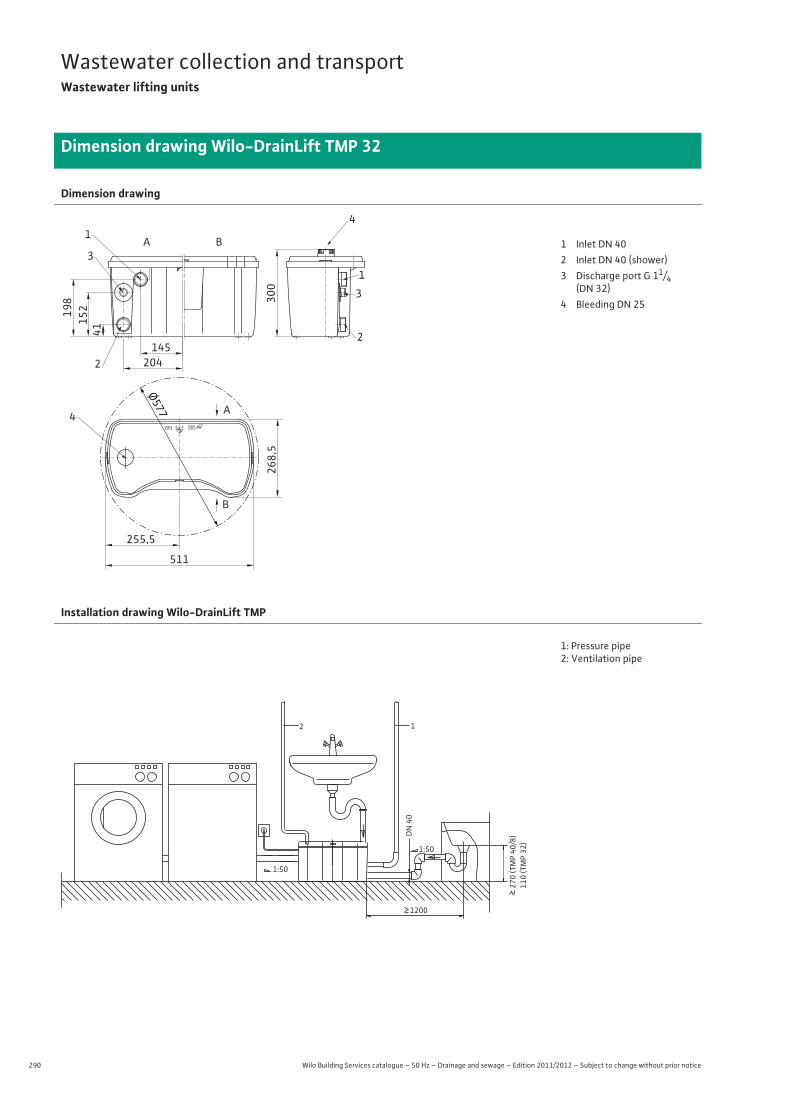
290 Wilo Building Services catalogue – 50 Hz – Drainage and sewage – Edition 2011/2012 – Subject to change without prior notice
Wastewater collection and transportWastewater lifting units
Dimension drawing Wilo-DrainLift TMP 32
Dimension drawing
A B3
1
198
152
41
145204
2
3
130
0
A
B
255,5
511
4
268,
5
2
4
Ø577
1 Inlet DN 402 Inlet DN 40 (shower)3 Discharge port G 11/4
(DN 32)4 Bleeding DN 25
Installation drawing Wilo-DrainLift TMP
1: Pressure pipe2: Ventilation pipe
1200
270
(TMP
40/8
)110
(TMP 32
)
DN
40
1:50
1:50
2 1
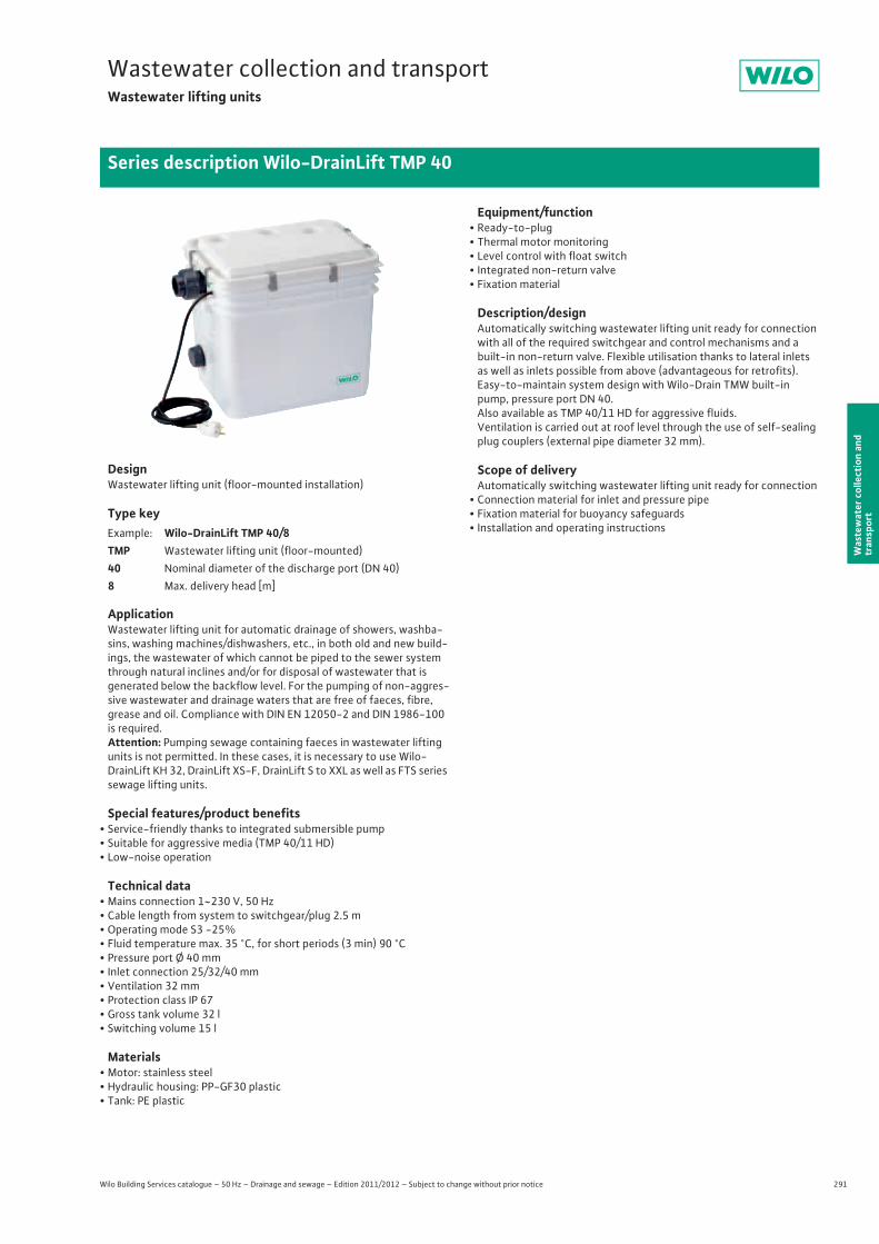
291
Wastewater collection and transportWastewater lifting units
Wilo Building Services catalogue – 50 Hz – Drainage and sewage – Edition 2011/2012 – Subject to change without prior notice
Series description Wilo-DrainLift TMP 40
Was
tew
ater
col
lect
ion
and
tran
spor
t
DesignWastewater lifting unit (floor-mounted installation)
Type key
ApplicationWastewater lifting unit for automatic drainage of showers, washba-sins, washing machines/dishwashers, etc., in both old and new build-ings, the wastewater of which cannot be piped to the sewer system through natural inclines and/or for disposal of wastewater that is generated below the backflow level. For the pumping of non-aggres-sive wastewater and drainage waters that are free of faeces, fibre, grease and oil. Compliance with DIN EN 12050-2 and DIN 1986-100 is required.Attention: Pumping sewage containing faeces in wastewater lifting units is not permitted. In these cases, it is necessary to use Wilo-DrainLift KH 32, DrainLift XS-F, DrainLift S to XXL as well as FTS series sewage lifting units.
Special features/product benefits• Service-friendly thanks to integrated submersible pump• Suitable for aggressive media (TMP 40/11 HD)• Low-noise operation
Technical data• Mains connection 1~230 V, 50 Hz• Cable length from system to switchgear/plug 2.5 m• Operating mode S3 -25%• Fluid temperature max. 35 °C, for short periods (3 min) 90 °C• Pressure port Ø 40 mm• Inlet connection 25/32/40 mm• Ventilation 32 mm• Protection class IP 67• Gross tank volume 32 l• Switching volume 15 l
Materials• Motor: stainless steel• Hydraulic housing: PP-GF30 plastic• Tank: PE plastic
Equipment/function• Ready-to-plug• Thermal motor monitoring• Level control with float switch• Integrated non-return valve• Fixation material
Description/designAutomatically switching wastewater lifting unit ready for connection with all of the required switchgear and control mechanisms and a built-in non-return valve. Flexible utilisation thanks to lateral inlets as well as inlets possible from above (advantageous for retrofits). Easy-to-maintain system design with Wilo-Drain TMW built-in pump, pressure port DN 40.Also available as TMP 40/11 HD for aggressive fluids.Ventilation is carried out at roof level through the use of self-sealing plug couplers (external pipe diameter 32 mm).
Scope of deliveryAutomatically switching wastewater lifting unit ready for connection
• Connection material for inlet and pressure pipe• Fixation material for buoyancy safeguards• Installation and operating instructionsExample: Wilo-DrainLift TMP 40/8
TMP Wastewater lifting unit (floor-mounted)40 Nominal diameter of the discharge port (DN 40)8 Max. delivery head [m]
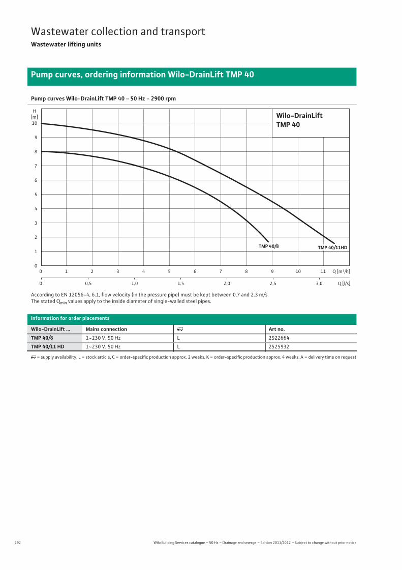
292 Wilo Building Services catalogue – 50 Hz – Drainage and sewage – Edition 2011/2012 – Subject to change without prior notice
Wastewater collection and transportWastewater lifting units
Pump curves, ordering information Wilo-DrainLift TMP 40
Pump curves Wilo-DrainLift TMP 40 - 50 Hz - 2900 rpm
According to EN 12056-4, 6.1, flow velocity (in the pressure pipe) must be kept between 0.7 and 2.3 m/s.The stated Qmin values apply to the inside diameter of single-walled steel pipes.
Information for order placements
Wilo-DrainLift ... Mains connection � Art no.TMP 40/8 1~230 V, 50 Hz L 2522664
TMP 40/11 HD 1~230 V, 50 Hz L 2525932
�= supply availability, L = stock article, C = order-specific production approx. 2 weeks, K = order-specific production approx. 4 weeks, A = delivery time on request
Wilo-DrainLiftTMP 40
2
3
0
5
6
7
8
9
10
4
1
H[m]
0 4 5 8 92 31 6 7 10 11
0 1,0 2,00,5 1,5 2,5 3,0
Q [m³/h]
Q [l/s]
TMP 40/8 TMP 40/11HD
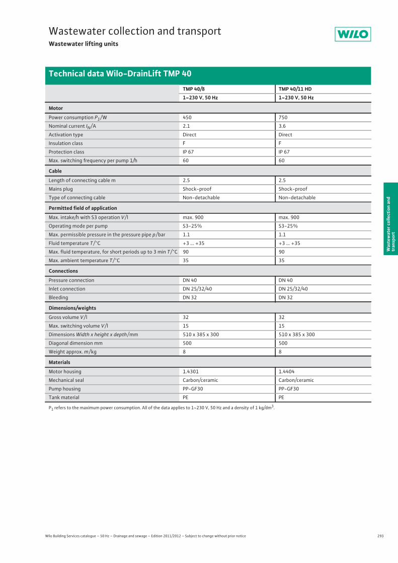
293
Wastewater collection and transportWastewater lifting units
Wilo Building Services catalogue – 50 Hz – Drainage and sewage – Edition 2011/2012 – Subject to change without prior notice
Technical data Wilo-DrainLift TMP 40
Was
tew
ater
col
lect
ion
and
tran
spor
t
TMP 40/8 TMP 40/11 HD1~230 V, 50 Hz 1~230 V, 50 Hz
Motor
Power consumption P1 / W 450 750
Nominal current IN / A 2.1 3.6
Activation type Direct Direct
Insulation class F F
Protection class IP 67 IP 67
Max. switching frequency per pump 1/h 60 60
Cable
Length of connecting cable m 2.5 2.5
Mains plug Shock-proof Shock-proof
Type of connecting cable Non-detachable Non-detachable
Permitted field of application
Max. intake/h with S3 operation V / l max. 900 max. 900
Operating mode per pump S3-25% S3-25%
Max. permissible pressure in the pressure pipe p / bar 1.1 1.1
Fluid temperature T / °C +3 ... +35 +3 ... +35
Max. fluid temperature, for short periods up to 3 min T / °C 90 90
Max. ambient temperature T / °C 35 35
Connections
Pressure connection DN 40 DN 40
Inlet connection DN 25/32/40 DN 25/32/40
Bleeding DN 32 DN 32
Dimensions/weights
Gross volume V / l 32 32
Max. switching volume V / l 15 15
Dimensions Width x height x depth / mm 510 x 385 x 300 510 x 385 x 300
Diagonal dimension mm 500 500
Weight approx. m / kg 8 8
Materials
Motor housing 1.4301 1.4404
Mechanical seal Carbon/ceramic Carbon/ceramic
Pump housing PP-GF30 PP-GF30
Tank material PE PE
P1 refers to the maximum power consumption. All of the data applies to 1~230 V, 50 Hz and a density of 1 kg/dm3.
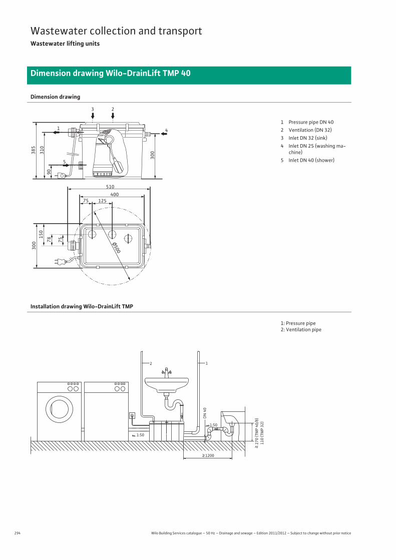
294 Wilo Building Services catalogue – 50 Hz – Drainage and sewage – Edition 2011/2012 – Subject to change without prior notice
Wastewater collection and transportWastewater lifting units
Dimension drawing Wilo-DrainLift TMP 40
Dimension drawing
385
1
5
3 2
4
310
300
90
300
150
78 75
510
40012575
Ø500
1 Pressure pipe DN 402 Ventilation (DN 32)3 Inlet DN 32 (sink)4 Inlet DN 25 (washing ma-
chine)5 Inlet DN 40 (shower)
Installation drawing Wilo-DrainLift TMP
1: Pressure pipe2: Ventilation pipe
1200
270
(TMP
40/8
)110
(TMP 32
)
DN
40
1:50
1:50
2 1
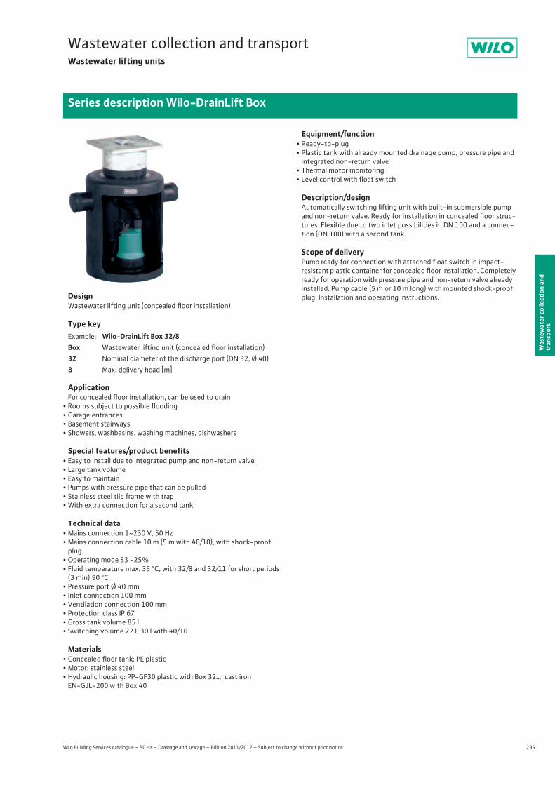
295
Wastewater collection and transportWastewater lifting units
Wilo Building Services catalogue – 50 Hz – Drainage and sewage – Edition 2011/2012 – Subject to change without prior notice
Series description Wilo-DrainLift Box
Was
tew
ater
col
lect
ion
and
tran
spor
t
DesignWastewater lifting unit (concealed floor installation)
Type key
ApplicationFor concealed floor installation, can be used to drain
• Rooms subject to possible flooding• Garage entrances• Basement stairways• Showers, washbasins, washing machines, dishwashers
Special features/product benefits• Easy to install due to integrated pump and non-return valve• Large tank volume• Easy to maintain• Pumps with pressure pipe that can be pulled• Stainless steel tile frame with trap• With extra connection for a second tank
Technical data• Mains connection 1~230 V, 50 Hz• Mains connection cable 10 m (5 m with 40/10), with shock-proof
plug• Operating mode S3 -25%• Fluid temperature max. 35 °C, with 32/8 and 32/11 for short periods
(3 min) 90 °C • Pressure port Ø 40 mm• Inlet connection 100 mm• Ventilation connection 100 mm• Protection class IP 67• Gross tank volume 85 l• Switching volume 22 l, 30 l with 40/10
Materials• Concealed floor tank: PE plastic• Motor: stainless steel• Hydraulic housing: PP-GF30 plastic with Box 32…, cast iron
EN-GJL-200 with Box 40
Equipment/function• Ready-to-plug• Plastic tank with already mounted drainage pump, pressure pipe and
integrated non-return valve• Thermal motor monitoring• Level control with float switch
Description/designAutomatically switching lifting unit with built-in submersible pump and non-return valve. Ready for installation in concealed floor struc-tures. Flexible due to two inlet possibilities in DN 100 and a connec-tion (DN 100) with a second tank.
Scope of deliveryPump ready for connection with attached float switch in impact-resistant plastic container for concealed floor installation. Completely ready for operation with pressure pipe and non-return valve already installed. Pump cable (5 m or 10 m long) with mounted shock-proof plug. Installation and operating instructions.
Example: Wilo-DrainLift Box 32/8Box Wastewater lifting unit (concealed floor installation)32 Nominal diameter of the discharge port (DN 32, Ø 40)8 Max. delivery head [m]
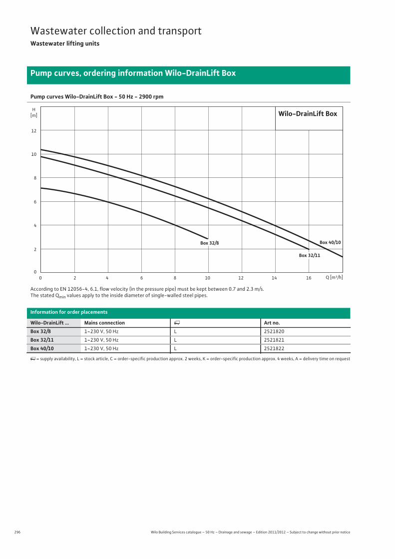
296 Wilo Building Services catalogue – 50 Hz – Drainage and sewage – Edition 2011/2012 – Subject to change without prior notice
Wastewater collection and transportWastewater lifting units
Pump curves, ordering information Wilo-DrainLift Box
Pump curves Wilo-DrainLift Box - 50 Hz - 2900 rpm
According to EN 12056-4, 6.1, flow velocity (in the pressure pipe) must be kept between 0.7 and 2.3 m/s.The stated Qmin values apply to the inside diameter of single-walled steel pipes.
Information for order placements
Wilo-DrainLift ... Mains connection � Art no.Box 32/8 1~230 V, 50 Hz L 2521820
Box 32/11 1~230 V, 50 Hz L 2521821
Box 40/10 1~230 V, 50 Hz L 2521822
�= supply availability, L = stock article, C = order-specific production approx. 2 weeks, K = order-specific production approx. 4 weeks, A = delivery time on request
Q [m³/h]0 2 4 6 8 10 12 14 16
H[m]
0
4
8
6
10
12
2
Wilo-DrainLift Box
Box 32/8
Box 32/11
Box 40/10
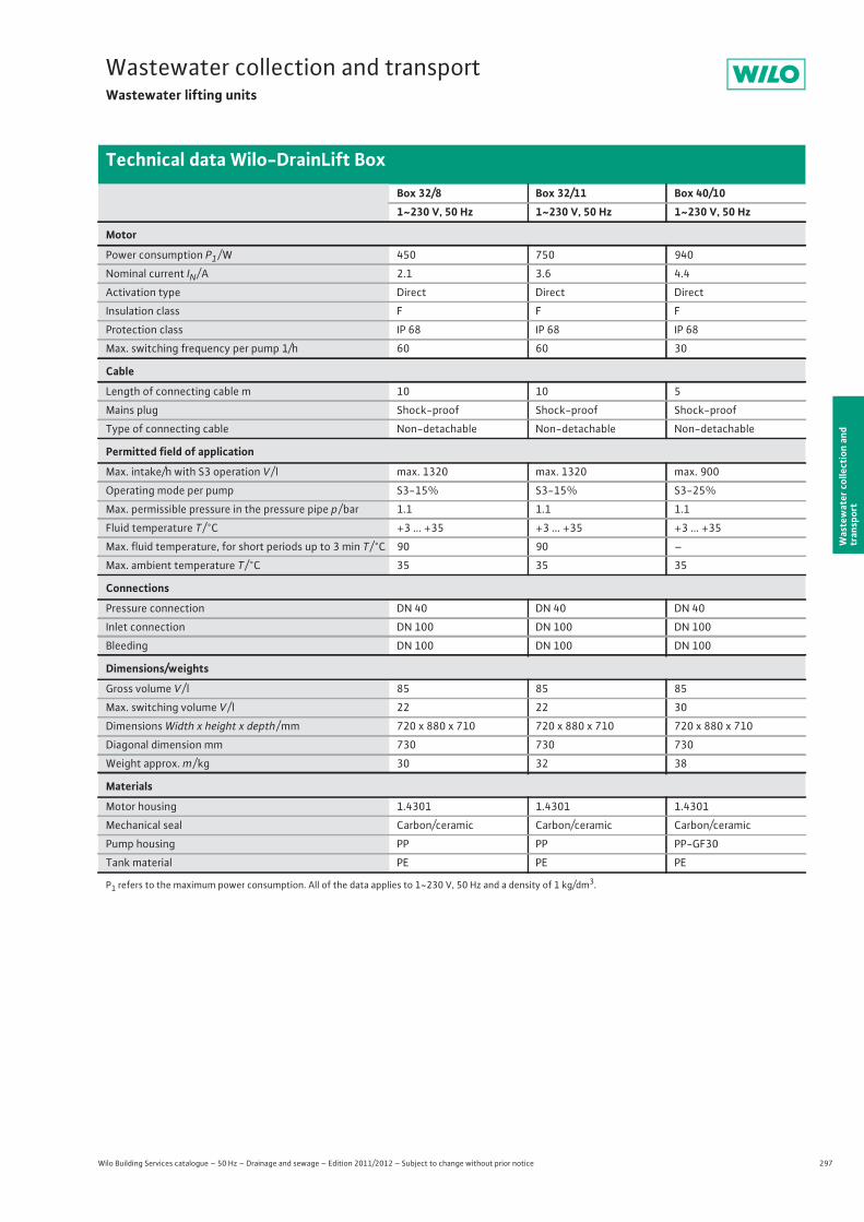
297
Wastewater collection and transportWastewater lifting units
Wilo Building Services catalogue – 50 Hz – Drainage and sewage – Edition 2011/2012 – Subject to change without prior notice
Technical data Wilo-DrainLift Box
Was
tew
ater
col
lect
ion
and
tran
spor
t
Box 32/8 Box 32/11 Box 40/101~230 V, 50 Hz 1~230 V, 50 Hz 1~230 V, 50 Hz
Motor
Power consumption P1 / W 450 750 940
Nominal current IN / A 2.1 3.6 4.4
Activation type Direct Direct Direct
Insulation class F F F
Protection class IP 68 IP 68 IP 68
Max. switching frequency per pump 1/h 60 60 30
Cable
Length of connecting cable m 10 10 5
Mains plug Shock-proof Shock-proof Shock-proof
Type of connecting cable Non-detachable Non-detachable Non-detachable
Permitted field of application
Max. intake/h with S3 operation V / l max. 1320 max. 1320 max. 900
Operating mode per pump S3-15% S3-15% S3-25%
Max. permissible pressure in the pressure pipe p / bar 1.1 1.1 1.1
Fluid temperature T / °C +3 ... +35 +3 ... +35 +3 ... +35
Max. fluid temperature, for short periods up to 3 min T / °C 90 90 –
Max. ambient temperature T / °C 35 35 35
Connections
Pressure connection DN 40 DN 40 DN 40
Inlet connection DN 100 DN 100 DN 100
Bleeding DN 100 DN 100 DN 100
Dimensions/weights
Gross volume V / l 85 85 85
Max. switching volume V / l 22 22 30
Dimensions Width x height x depth / mm 720 x 880 x 710 720 x 880 x 710 720 x 880 x 710
Diagonal dimension mm 730 730 730
Weight approx. m / kg 30 32 38
Materials
Motor housing 1.4301 1.4301 1.4301
Mechanical seal Carbon/ceramic Carbon/ceramic Carbon/ceramic
Pump housing PP PP PP-GF30
Tank material PE PE PE
P1 refers to the maximum power consumption. All of the data applies to 1~230 V, 50 Hz and a density of 1 kg/dm3.
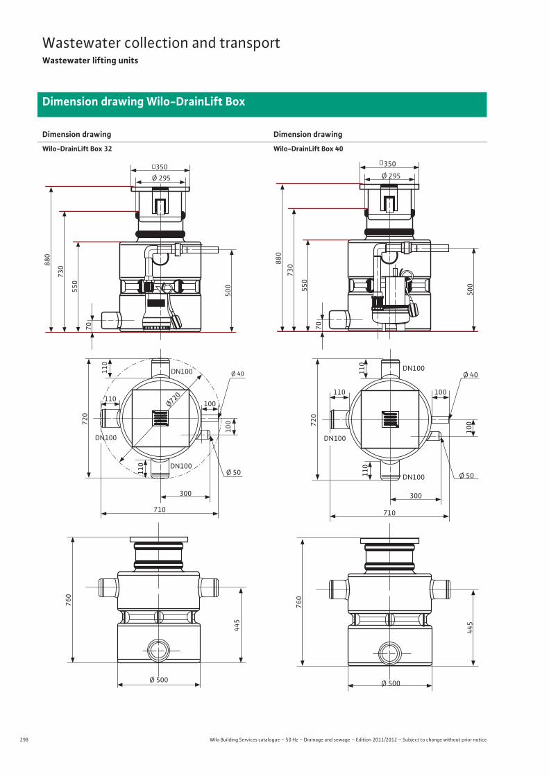
298 Wilo Building Services catalogue – 50 Hz – Drainage and sewage – Edition 2011/2012 – Subject to change without prior notice
Wastewater collection and transportWastewater lifting units
Dimension drawing Wilo-DrainLift Box
Dimension drawing
Wilo-DrainLift Box 32
Dimension drawing
Wilo-DrainLift Box 40
Ø 500
445
760
Ø 50
Ø 295350
720
110
110
100
DN100
DN100
DN100
100110
300
710
880
730
550
70
500
Ø 40
Ø720
Ø 500
445
760
Ø 40
Ø 50
Ø 295
350
720
110
110
100
DN100
DN100
DN100
100110
300
710
880
730
550
70
500
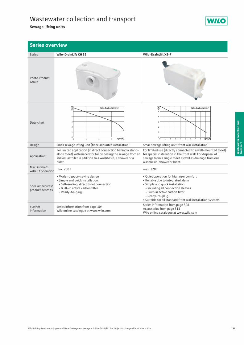
299
Wastewater collection and transportSewage lifting units
Wilo Building Services catalogue – 50 Hz – Drainage and sewage – Edition 2011/2012 – Subject to change without prior notice
Series overview
Was
tew
ater
col
lect
ion
and
tran
spor
t
Series Wilo-DrainLift KH 32 Wilo-DrainLift XS-F
Photo Product Group
Duty chart
Design Small sewage lifting unit (floor-mounted installation) Small sewage lifting unit (front wall installation)
Application
For limited application (in direct connection behind a stand-alone toilet) with macerator for disposing the sewage from an individual toilet in addition to a washbasin, a shower or abidet.
For limited use (directly connected to a wall-mounted toilet) for special installation in the front wall. For disposal ofsewage from a single toilet as well as drainage from one washbasin, shower or bidet.
Max. intake/h with S3 operation max. 260 l max. 120 l
Special features/product benefits
• Modern, space-saving design• Simple and quick installation:
- Self-sealing, direct toilet connection- Built-in active carbon filter- Ready-to-plug
• Quiet operation for high user comfort• Reliable due to integrated alarm• Simple and quick installation:
- Including all connection sleeves- Built-in active carbon filter- Ready-to-plug
• Suitable for all standard front wall installation systems
Furtherinformation
Series information from page 304 Wilo online catalogue at www.wilo.com
Series information from page 308 Accessories from page 313Wilo online catalogue at www.wilo.com
Q[m³/h]0 1 2 3
H[m]
0
2
1
4
3
Wilo-DrainLift KH 32
Q[m³/h]0 1 2 3 4 5 6 7 8
H[m]
0
2
1
4
3
5
Wilo-DrainLift XS-F

300 Wilo Building Services catalogue – 50 Hz – Drainage and sewage – Edition 2011/2012 – Subject to change without prior notice
Wastewater collection and transportSewage lifting units
Series overview
Series Wilo-DrainLift S Wilo-DrainLift M
Photo Product Group
Duty chart
Design Compact sewage lifting unit with integrated pump Sewage lifting unit with 1 or 2 integrated pumps
Application
• For the pumping of raw sewage that cannot be piped to the sewer system through the use of natural inclines.
• Drainage of individual rooms
• Pumping of untreated sewage that cannot be conveyed to the sewer system via natural slope.
• For drainage of single-family houses and small building complexes.
Max. intake/h with S3 operation max. 600 l max. 1,080 ... 3,600 l
Special features/product benefits
• Easy to install due to:- Low weight- Large scope of delivery
• Flexible due to:- Freely selectable inlets- Front-wall-like installation- Space-saving installation (depth 30 cm)
• Safe due to:- Reliable pneumatic level measurement
• Easy to install due to:- Compact dimensions- Low weight- Large scope of delivery
• Flexible due to:- Freely selectable inlets
• Safe due to:- Integrated mains-independent alarm function- Integrated thermal motor protection- Additional potential-free contact- Maintenance interval display for M2- Early fault detection for M2
Furtherinformation
Series information from page 314Accessories from page 321Wilo online catalogue at www.wilo.com
Series information from page 323 Accessories from page 333Wilo online catalogue at www.wilo.com
Q[m³/h]0 4 8 12 16 20 24
H[m
]
0
1,0
2,0
3,0
4,0
5,0
S 1/5
Wilo-DrainLift S
M 1/8M 2/8
Q[m³/h]0 5 10 15 20 25 30
H[m
]
012345678
Wilo-DrainLift M
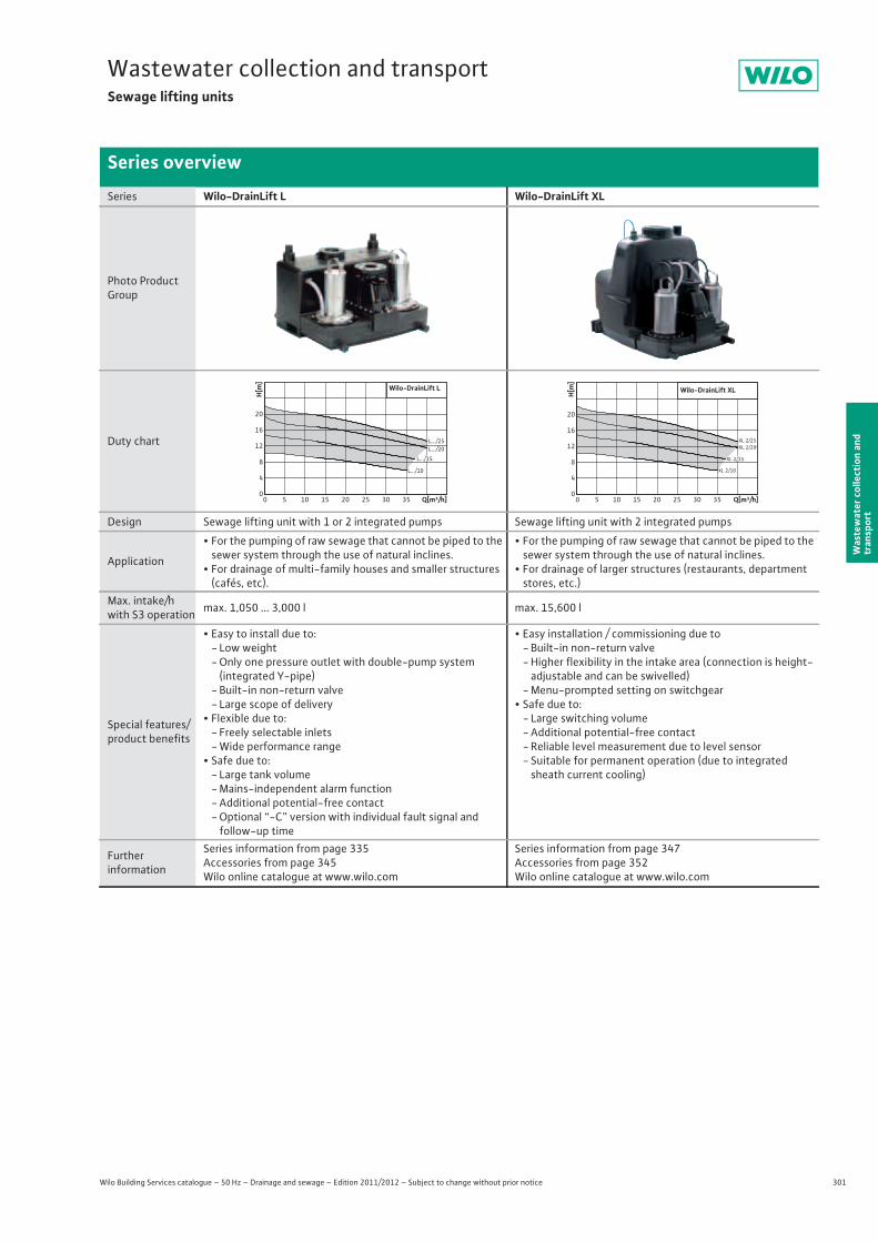
301
Wastewater collection and transportSewage lifting units
Wilo Building Services catalogue – 50 Hz – Drainage and sewage – Edition 2011/2012 – Subject to change without prior notice
Series overview
Was
tew
ater
col
lect
ion
and
tran
spor
t
Series Wilo-DrainLift L Wilo-DrainLift XL
Photo Product Group
Duty chart
Design Sewage lifting unit with 1 or 2 integrated pumps Sewage lifting unit with 2 integrated pumps
Application
• For the pumping of raw sewage that cannot be piped to the sewer system through the use of natural inclines.
• For drainage of multi-family houses and smaller structures (cafés, etc).
• For the pumping of raw sewage that cannot be piped to the sewer system through the use of natural inclines.
• For drainage of larger structures (restaurants, department stores, etc.)
Max. intake/h with S3 operation max. 1,050 ... 3,000 l max. 15,600 l
Special features/product benefits
• Easy to install due to:- Low weight- Only one pressure outlet with double-pump system
(integrated Y-pipe)- Built-in non-return valve- Large scope of delivery
• Flexible due to:- Freely selectable inlets- Wide performance range
• Safe due to:- Large tank volume- Mains-independent alarm function- Additional potential-free contact - Optional “-C” version with individual fault signal and
follow-up time
• Easy installation / commissioning due to- Built-in non-return valve- Higher flexibility in the intake area (connection is height-adjustable and can be swivelled)
- Menu-prompted setting on switchgear• Safe due to:
- Large switching volume- Additional potential-free contact- Reliable level measurement due to level sensor- Suitable for permanent operation (due to integrated
sheath current cooling)
Furtherinformation
Series information from page 335 Accessories from page 345Wilo online catalogue at www.wilo.com
Series information from page 347 Accessories from page 352Wilo online catalogue at www.wilo.com
L.../10
L.../25L.../20
Q[m³/h]0 5 10 15 20 25 30 35
H[m
]
0
4
8
12
16
20
L.../15
Wilo-DrainLift L
XL 2/10
XL 2/25
Q[m³/h]0 5 10 15 20 25 30 35
H[m
]
0
4
8
12
16
20
Wilo-DrainLift XL
XL 2/20
XL 2/15
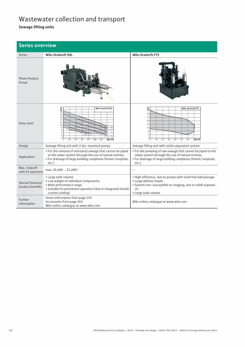
302 Wilo Building Services catalogue – 50 Hz – Drainage and sewage – Edition 2011/2012 – Subject to change without prior notice
Wastewater collection and transportSewage lifting units
Series overview
Series Wilo-DrainLift XXL Wilo-DrainLift FTS
Photo Product Group
Duty chart
Design Sewage lifting unit with 2 dry-mounted pumps Sewage lifting unit with solids separation system
Application
• For the removal of untreated sewage that cannot be piped to the sewer system through the use of natural inclines.
• For drainage of large building complexes (hotels, hospitals, etc.).
• For the pumping of raw sewage that cannot be piped to the sewer system through the use of natural inclines.
• For drainage of large building complexes (hotels, hospitals, etc.).
Max. intake/h with S3 operation max. 26,400 ... 55,200 l –
Special features/product benefits
• Large tank volume• Low weight of individual components• Wide performance range• Suitable for permanent operation (due to integrated sheath
current cooling)
• High efficiency, due to pumps with small free ball passage• Large delivery heads• System non-susceptible to clogging, due to solids separati-
on• Large tank volume
Furtherinformation
Series information from page 354 Accessories from page 363Wilo online catalogue at www.wilo.com
Wilo online catalogue at www.wilo.com
Q[m³/h]0 20 40 60 80 100 120
H[m
]
02468
101214161820
Wilo-DrainLift XXL
XXL 8..-2/1,7
XXL 10..-2/8,4
XXL 10..-2/5,2
XXL 10..-2/3,9
XXL 10..-2/7,0
XXL 8..-2/2,1
Q[m³/h]0 10 20 30 40 50 60
H[m
]
0
4
8
12
16
20
24
28
Wilo-DrainLift FTS
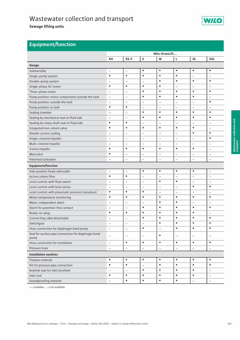
303
Wastewater collection and transportSewage lifting units
Wilo Building Services catalogue – 50 Hz – Drainage and sewage – Edition 2011/2012 – Subject to change without prior notice
Equipment/function
Was
tew
ater
col
lect
ion
and
tran
spor
t
Wilo-DrainLift ...KH XS-F S M L XL XXL
Design
Submersible – – • • • • •Single-pump system • • • • • - -
Double-pump system – – – • • • •Single-phase AC motor • • • • – – –
Three-phase motor – – • • • • •Pump position: motor components outside the tank – – • • • • –
Pump position: outside the tank – – – – – – •Pump position: in tank • • – – – – –
Sealing chamber – – • • • • •Sealing by mechanical seal on fluid side – – • • • • •Sealing by rotary shaft seal on fluid side • • – – – – –
Integrated non-return valve • • • • • • –
Sheath current cooling – – – – – • •Single-channel impeller – – – – – – •Multi-channel impeller – – – – – – –
Vortex impeller • • • • • • –
Macerator • – – – – – –
Patented turbulator – – – – – – –
Equipment/function
Inlet position freely selectable – – • • • • –
Active carbon filter • • – – – – –
Level control: with float switch – – – • • – –
Level control: with level sensor – – – – – • •Level control: with pneumatic pressure transducer • • • – – – –
Motor temperature monitoring • • • • • • •Mains-independent alarm – – – • • – –
Alarm for potential-free contact – – • • • • •Ready-to-plug • • • • • • –
Connecting cable detachable – – • • • • •Switchgear – – – • • • •Hose connection for diaphragm hand pump – – • – • • •Seal for suction pipe connection for diaphragm hand pump – – – • – – –
Hose connection for ventilation – • • • • • •Pressure hose – – – – – – –
Installation sundries
Fixation material • • • • • • •Kit for pressure pipe connection • • – • • • •Keyhole saw for inlet borehole – – • • • • –
Inlet seal • • • • • • –
Soundproofing material – • • • • – –
• = available, - = not available
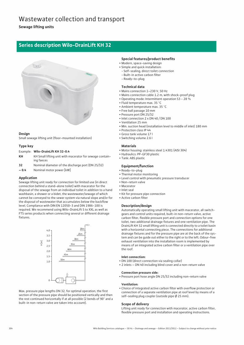
304 Wilo Building Services catalogue – 50 Hz – Drainage and sewage – Edition 2011/2012 – Subject to change without prior notice
Wastewater collection and transportSewage lifting units
Series description Wilo-DrainLift KH 32
DesignSmall sewage lifting unit (floor-mounted installation)
Type key
ApplicationSewage lifting unit ready for connection for limited use (in direct connection behind a stand-alone toilet) with macerator for thedisposal of the sewage from an individual toilet in addition to a hand washbasin, a shower or a bidet, the wastewater/sewage of which cannot be conveyed to the sewer system via natural slope and/or for the disposal of wastewater that accumulates below the backflow level. Compliance with DIN EN 12050-3 and DIN 1986-100 isrequired. We recommend using Wilo-DrainLift S to XXL as well asFTS series products when connecting several or different drainage fixtures.
Max. pressure pipe lengths DN 32, for optimal operation, the first section of the pressure pipe should be positioned vertically and then the rest continued horizontally if at all possible (2 bends of 90° and a built-in non-return valve are taken into account).
Special features/product benefits• Modern, space-saving design• Simple and quick installation:
- Self-sealing, direct toilet connection- Built-in active carbon filter- Ready-to-plug
Technical data• Mains connection 1~230 V, 50 Hz• Mains connection cable 1.2 m, with shock-proof plug• Operating mode: Intermittent operation S3 - 28 %• Fluid temperature max. 35 °C• Ambient temperature max. 35 °C • Free ball passage 10 mm• Pressure port DN 25/32• Inlet connection 2 x DN 40 / DN 100• Ventilation 25 mm• Min. suction head (installation level to middle of inlet) 180 mm• Protection class IP 44• Gross tank volume 17 l• Switching volume 2.6 l
Materials• Motor housing: stainless steel 1.4301 (AISI 304)• Hydraulics: PP-GF30 plastic• Tank: ABS plastic
Equipment/function• Ready-to-plug• Thermal motor monitoring• Level control with pneumatic pressure transducer• Non-return valve• Macerator• Inlet seal• Kit for pressure pipe connection• Active carbon filter
Description/designAutomatically operating small lifting unit with macerator, all switch-gears and control units required, built-in non-return valve, active carbon filter, flexible pressure port and connection options for one toilet, two additional drainage fixtures and one ventilation pipe. The DrainLift KH 32 small lifting unit is connected directly to a toilet basin with a horizontal connecting piece. The connections for additional drainage fixtures and for the pressure pipe are at the back of the sys-tem and can be guide out either to the right or to the left. Odour-free exhaust ventilation into the installation room is implemented by means of an integrated active carbon filter or a ventilation pipe over the roof.
Inlet connection:• DN 100 (direct connection via sealing collar)• 2 inlets – DN 40 including blind cover and a non-return valve
Connection pressure side:• Pressure port hose angle DN 25/32 including non-return valve
Ventilation:• Choice of integrated active carbon filter with overflow protection or
connection of a separate ventilation pipe at roof level by means of a self-sealing plug coupler (outside pipe Ø 25 mm).
Scope of deliveryLifting unit ready for connection with macerator, active carbon filter, flexible pressure port and installation and operating instructions.
Example: Wilo-DrainLift KH 32-0.4KH KH Small lifting unit with macerator for sewage contain-
ing faeces32 Nominal diameter of the discharge port (DN 25/32)– 0.4 Nominal motor power [kW]
4,020 m
25 m
30 m
35 m
40 m
50 m
45 m
3,5
3,0
2,5
2,0
1,5
1,0
0
H [m
]
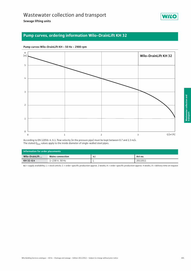
305
Wastewater collection and transportSewage lifting units
Wilo Building Services catalogue – 50 Hz – Drainage and sewage – Edition 2011/2012 – Subject to change without prior notice
Pump curves, ordering information Wilo-DrainLift KH 32
Was
tew
ater
col
lect
ion
and
tran
spor
t
Pump curves Wilo-DrainLift KH - 50 Hz - 2900 rpm
According to EN 12056-4, 6.1, flow velocity (in the pressure pipe) must be kept between 0.7 and 2.3 m/s.The stated Qmin values apply to the inside diameter of single-walled steel pipes.
Information for order placements
Wilo-DrainLift ... Mains connection � Art no.KH 32-0,4 1~230 V, 50 Hz L 2011011
�= supply availability, L = stock article, C = order-specific production approx. 2 weeks, K = order-specific production approx. 4 weeks, A = delivery time on request
Q [m³/h]0 1 2 3
H[m]
0
2
1
4
3
5
Wilo-DrainLift KH 32

306 Wilo Building Services catalogue – 50 Hz – Drainage and sewage – Edition 2011/2012 – Subject to change without prior notice
Wastewater collection and transportSewage lifting units
Technical data Wilo-DrainLift KH 32
Wilo-DrainLift ...KH 32-0,4
Motor
Mains connection 1~230 V, 50 Hz
Power consumption P1 / kW 0.5
Nominal current IN / A 2.1
Nominal speed n / rpm 2900
Activation type Direct
Insulation class F
Protection class IP 44
Max. switching frequency per pump 1/h 100
Cable
Cable length from system to switchgear/plug m –/1.2
Mains plug Shock-proof
Type of connecting cable Non-detachable
Permitted field of application
Max. intake/h with S3 operation V / l max. 260
Operating mode per pump S3-25%
Max. permissible pressure in the pressure pipe p / bar 0.7
Fluid temperature T / °C +3 ... +35
Max. fluid temperature, for short periods up to 3 min T / °C –
Max. ambient temperature T / °C 35
Connections
Pressure connection DN 25/DN 32
Inlet connection 2x DN 40/1x DN 100
Bleeding DN 25
Dimensions/weights
Gross volume V / l 17
Switching volume V / l 2.6
Min. water level OFF mm –
Min. water level ON mm 70
Dimensions Width x height x depth / mm 500 x 300 x 269
Diagonal dimension mm 520
Weight approx. m / kg 7.8
Materials
Motor housing 1.4301
Pump shaft –
Mechanical seal Carbon/ceramic
Pump housing PP
Impeller PP
Tank material ABS
P1 refers to the maximum power consumption. All of the data applies to 1~230 V, 50 Hz and a density of 1 kg/dm3.
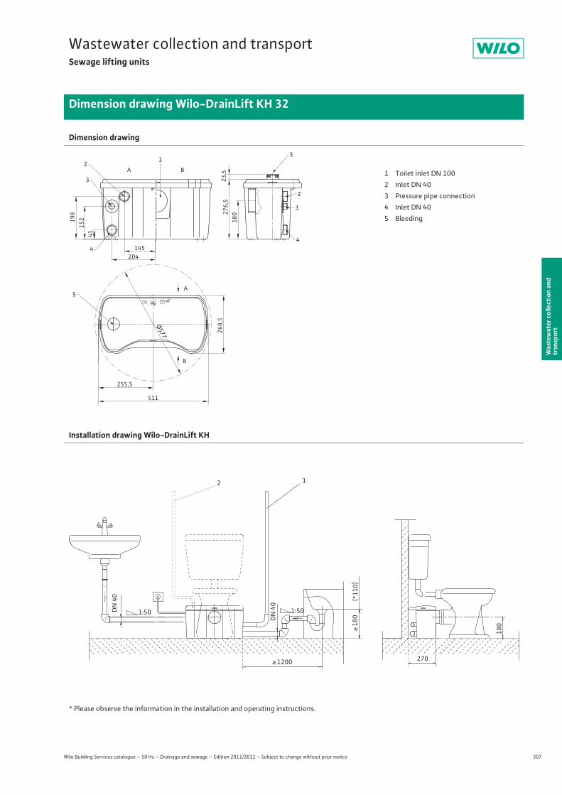
307
Wastewater collection and transportSewage lifting units
Wilo Building Services catalogue – 50 Hz – Drainage and sewage – Edition 2011/2012 – Subject to change without prior notice
Dimension drawing Wilo-DrainLift KH 32
Was
tew
ater
col
lect
ion
and
tran
spor
t
Dimension drawing
A B
3
21
5
198
152
41
145204
44
3
2
276,
518
0
A
B
255,5
Ø577
511
5
268,
523
,5 1 Toilet inlet DN 1002 Inlet DN 403 Pressure pipe connection4 Inlet DN 405 Bleeding
Installation drawing Wilo-DrainLift KH
* Please observe the information in the installation and operating instructions.
(*11
0)�
180
180
270� 1200
DN
40
12
1:50DN
40
1:50
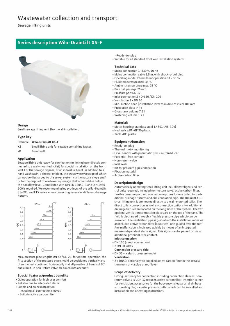
308 Wilo Building Services catalogue – 50 Hz – Drainage and sewage – Edition 2011/2012 – Subject to change without prior notice
Wastewater collection and transportSewage lifting units
Series description Wilo-DrainLift XS-F
DesignSmall sewage lifting unit (front wall installation)
Type key
ApplicationSewage lifting unit ready for connection for limited use (directly con-nected to a wall-mounted toilet) for special installation on the front wall. For the sewage disposal of an individual toilet, in addition to a hand washbasin, a shower or bidet, the wastewater/sewage of which cannot be discharged to the sewer system via the natural slope and/or for the disposal of wastewater/sewage that accumulates below the backflow level. Compliance with DIN EN 12050-3 and DIN 1986-100 is required. We recommend using products of the Wilo-DrainLift S to XXL and FTS series when connecting several or different drainage fixtures.
Max. pressure pipe lengths DN 32 / DN 25, for optimal operation, the first section of the pressure pipe should be positioned vertically and then the rest continued horizontally if at all possible (2 bends of 90° and a built-in non-return valve are taken into account)
Special features/product benefits• Quiet operation for high user comfort• Reliable due to integrated alarm• Simple and quick installation:
- Including all connection sleeves- Built-in active carbon filter
- Ready-to-plug• Suitable for all standard front wall installation systems
Technical data• Mains connection 1~230 V, 50 Hz• Mains connection cable 1.5 m, with shock-proof plug• Operating mode: Intermittent operation S3 - 30 %• Fluid temperature max. 35 °C• Ambient temperature max. 35 °C • Free ball passage 25 mm• Pressure port DN 32• Inlet connection 2 x DN 50 / DN 100• Ventilation 2 x DN 50 • Min. suction head (installation level to middle of inlet) 180 mm• Protection class IP 44• Gross tank volume 7.9 l• Switching volume 1.2 l
Materials• Motor housing: stainless steel 1.4301 (AISI 304)• Hydraulics: PP-GF 30 plastic• Tank: ABS plastic
Equipment/function• Ready-to-plug• Thermal motor monitoring• Level control with pneumatic pressure transducer• Potential-free contact• Non-return valve• Inlet seals• Kit for pressure pipe connection• Fixation material • Active carbon filter
Description/designAutomatically operating small lifting unit incl. all switchgear and con-trol units required , included non-return valve, active carbon filter, flexible pressure port and connection options for one toilet, two ad-ditional drainage fixtures and one ventilation pipe. The DrainLift XS-F small lifting unit is connected directly to a wall-mounted toilet. The direct toilet connection as well as connection options for additional drainage fixtures are located on the long sides of the system. The two optional ventilation connection pieces are on the top of the tank. The fluid is discharged through a flexible pressure pipe which can be swivelled. The ventilation pipe is guided into the installation room via an included active carbon filter (odourless) or is guided over the roof. Any malfunction is indicated quickly by means of an integrated, mains-independent alarm signal. This signal can be passed on via an additional potential-free contact.Inlet connection:
• DN 100 (direct connection)• 2 DN 50 inlets
Connection pressure side:• DN 32 via elastic pressure outlet
Ventilation:• 2 x DN50; optionally via supplied active carbon filter in the installa-
tion room or via pipe at roof level
Scope of deliveryLifting unit ready for connection including connection sleeves, non-return valve 1 ¼", DN 32 reducer, active carbon filter, insertion screen for ventilation, accessories for the buoyancy safeguards, drain hose with sealing plugs, elastic pressure outlet which can be swivelled and installation and operating instructions.
Example: Wilo-DrainLift XS-FXS Small lifting unit for sewage containing faeces-F Front wall
4,0
DN 32 DN 252 m
11 m
20 m
29 m
39 m
48 m
57 m
3,5
3,0
2,5
2,0
1,5
1,0
0,5
0
H[m]
65 m
4,0
3 m
7 m
11 m
15 m
19 m
3,5
3,0
2,5
2,0
1,5
1,0
0,5
0
H[m]
23 m

309
Wastewater collection and transportSewage lifting units
Wilo Building Services catalogue – 50 Hz – Drainage and sewage – Edition 2011/2012 – Subject to change without prior notice
Pump curves, ordering information Wilo-DrainLift XS-F
Was
tew
ater
col
lect
ion
and
tran
spor
t
Pump curves Wilo-DrainLift XS-F - 50 Hz - 2900 rpm
According to EN 12056-4, 6.1, flow velocity (in the pressure pipe) must be kept between 0.7 and 2.3 m/s.The stated Qmin values apply to the inside diameter of single-walled steel pipes.
Information for order placements
Wilo-DrainLift ... Mains connection � Art no.XS-F 1~230 V, 50 Hz L 2526945
�= supply availability, L = stock article, C = order-specific production approx. 2 weeks, K = order-specific production approx. 4 weeks, A = delivery time on request
Q [m³/h]0 1 2 3 4 5 6 7 8 9
H[m]
0
2
1
4
3
5
6
0 0,5 1,0 1,5 2,52,0 Q [l/s]
Wilo-DrainLift XS-F
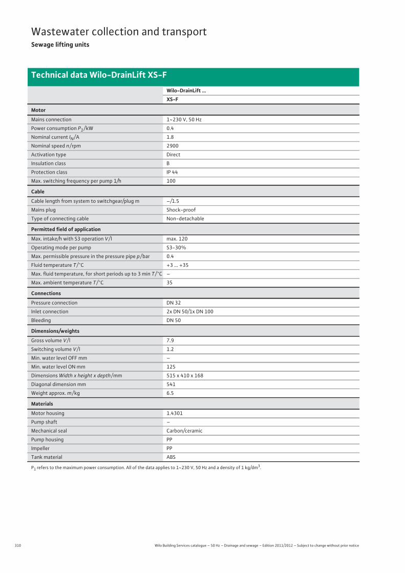
310 Wilo Building Services catalogue – 50 Hz – Drainage and sewage – Edition 2011/2012 – Subject to change without prior notice
Wastewater collection and transportSewage lifting units
Technical data Wilo-DrainLift XS-F
Wilo-DrainLift ...XS-F
Motor
Mains connection 1~230 V, 50 Hz
Power consumption P1 / kW 0.4
Nominal current IN / A 1.8
Nominal speed n / rpm 2900
Activation type Direct
Insulation class B
Protection class IP 44
Max. switching frequency per pump 1/h 100
Cable
Cable length from system to switchgear/plug m –/1.5
Mains plug Shock-proof
Type of connecting cable Non-detachable
Permitted field of application
Max. intake/h with S3 operation V / l max. 120
Operating mode per pump S3-30%
Max. permissible pressure in the pressure pipe p / bar 0.4
Fluid temperature T / °C +3 ... +35
Max. fluid temperature, for short periods up to 3 min T / °C –
Max. ambient temperature T / °C 35
Connections
Pressure connection DN 32
Inlet connection 2x DN 50/1x DN 100
Bleeding DN 50
Dimensions/weights
Gross volume V / l 7.9
Switching volume V / l 1.2
Min. water level OFF mm –
Min. water level ON mm 125
Dimensions Width x height x depth / mm 515 x 410 x 168
Diagonal dimension mm 541
Weight approx. m / kg 6.5
Materials
Motor housing 1.4301
Pump shaft –
Mechanical seal Carbon/ceramic
Pump housing PP
Impeller PP
Tank material ABS
P1 refers to the maximum power consumption. All of the data applies to 1~230 V, 50 Hz and a density of 1 kg/dm3.
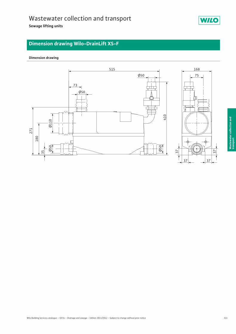
311
Wastewater collection and transportSewage lifting units
Wilo Building Services catalogue – 50 Hz – Drainage and sewage – Edition 2011/2012 – Subject to change without prior notice
Dimension drawing Wilo-DrainLift XS-F
Was
tew
ater
col
lect
ion
and
tran
spor
t
Dimension drawing
Ø110
Ø50
Ø50 75
168
73
515
Ø50
Ø50
37 37
37 37
35
180
271
410
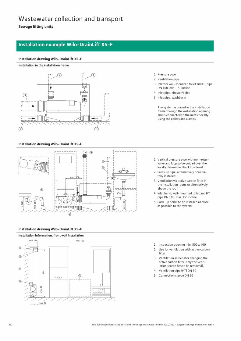
312 Wilo Building Services catalogue – 50 Hz – Drainage and sewage – Edition 2011/2012 – Subject to change without prior notice
Wastewater collection and transportSewage lifting units
Installation example Wilo-DrainLift XS-F
Installation drawing Wilo-DrainLift XS-F
Installation in the installation frame
Installation drawing Wilo-DrainLift XS-F
Installation drawing Wilo-DrainLift XS-F
Installation information, front wall installation
4 5
3
12 1 Pressure pipe2 Ventilation pipe3 Inlet for wall-mounted toilet and HT pipe DN 100, min. 15° incline
4 Inlet pipe, shower/bidet5 Inlet pipe, washbasin
The system is placed in the installation frame through the installation opening and is connected to the inlets flexibly using the collars and clamps.
2%
15°
max. 350
min
. 180
Ø50
min
. 180
220
>
220
A*
A*
3
2
1
5
4
1 Vertical pressure pipe with non-return valve and loop to be guided over the locally determined backflow level.
2 Pressure pipe, alternatively horizon-tally installed
3 Ventilation via active carbon filter in the installation room, or alternatively above the roof.
4 Inlet bend, wall-mounted toilet and HT pipe DN 100, min. 15° incline.
5 Back-up bend, to be installed as close as possible to the system
min. 180 min. 550
min
. 37
max. 37
850
5
1
4
3
21 Inspection opening min. 500 x 4002 Use for ventilation with active carbon
filter3 Ventilation screen (for changing the
active carbon filter, only the venti-lation screen has to be removed).
4 Ventilation pipe (HT) DN 50 5 Connection sleeve DN 50
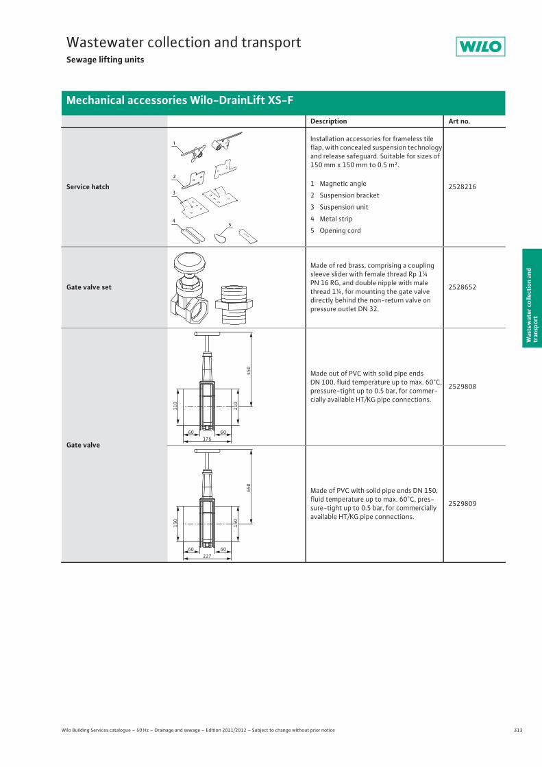
313
Wastewater collection and transportSewage lifting units
Wilo Building Services catalogue – 50 Hz – Drainage and sewage – Edition 2011/2012 – Subject to change without prior notice
Mechanical accessories Wilo-DrainLift XS-F
Was
tew
ater
col
lect
ion
and
tran
spor
t
Description Art no.
Service hatch
Installation accessories for frameless tile flap, with concealed suspension technology and release safeguard. Suitable for sizes of 150 mm x 150 mm to 0.5 m².
2528216
Gate valve set
Made of red brass, comprising a coupling sleeve slider with female thread Rp 1¼ PN 16 RG, and double nipple with male thread 1¼, for mounting the gate valvedirectly behind the non-return valve on pressure outlet DN 32.
2528652
Gate valve
Made out of PVC with solid pipe ends DN 100, fluid temperature up to max. 60°C, pressure-tight up to 0.5 bar, for commer-cially available HT/KG pipe connections.
2529808
Made of PVC with solid pipe ends DN 150, fluid temperature up to max. 60°C, pres-sure-tight up to 0.5 bar, for commercially available HT/KG pipe connections.
2529809
54
1
2
3
1 Magnetic angle
2 Suspension bracket
3 Suspension unit
4 Metal strip
5 Opening cord
60 60
110
110
450
176
60 60
150
150
650
227
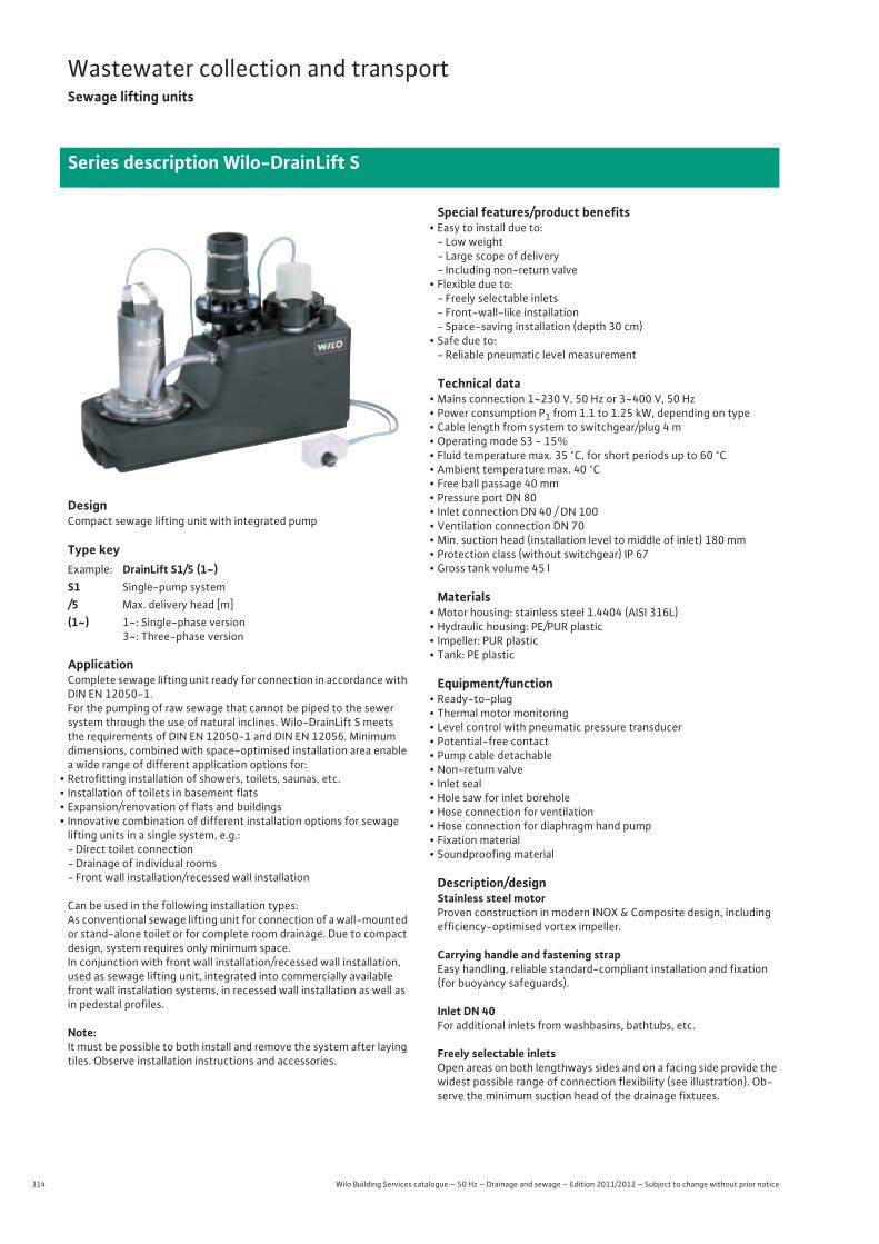
314 Wilo Building Services catalogue – 50 Hz – Drainage and sewage – Edition 2011/2012 – Subject to change without prior notice
Wastewater collection and transportSewage lifting units
Series description Wilo-DrainLift S
DesignCompact sewage lifting unit with integrated pump
Type key
ApplicationComplete sewage lifting unit ready for connection in accordance with DIN EN 12050-1.For the pumping of raw sewage that cannot be piped to the sewer system through the use of natural inclines. Wilo-DrainLift S meets the requirements of DIN EN 12050-1 and DIN EN 12056. Minimum dimensions, combined with space-optimised installation area enable a wide range of different application options for:
• Retrofitting installation of showers, toilets, saunas, etc.• Installation of toilets in basement flats• Expansion/renovation of flats and buildings• Innovative combination of different installation options for sewage
lifting units in a single system, e.g.:-Direct toilet connection-Drainage of individual rooms- Front wall installation/recessed wall installation
Can be used in the following installation types:As conventional sewage lifting unit for connection of a wall-mounted or stand-alone toilet or for complete room drainage. Due to compact design, system requires only minimum space.In conjunction with front wall installation/recessed wall installation, used as sewage lifting unit, integrated into commercially available front wall installation systems, in recessed wall installation as well as in pedestal profiles.
Note:It must be possible to both install and remove the system after laying tiles. Observe installation instructions and accessories.
Special features/product benefits• Easy to install due to:
- Low weight- Large scope of delivery- Including non-return valve
• Flexible due to:- Freely selectable inlets- Front-wall-like installation- Space-saving installation (depth 30 cm)
• Safe due to:- Reliable pneumatic level measurement
Technical data• Mains connection 1~230 V, 50 Hz or 3~400 V, 50 Hz• Power consumption P1 from 1.1 to 1.25 kW, depending on type• Cable length from system to switchgear/plug 4 m• Operating mode S3 - 15%• Fluid temperature max. 35 °C, for short periods up to 60 °C• Ambient temperature max. 40 °C• Free ball passage 40 mm• Pressure port DN 80• Inlet connection DN 40 / DN 100• Ventilation connection DN 70• Min. suction head (installation level to middle of inlet) 180 mm• Protection class (without switchgear) IP 67• Gross tank volume 45 l
Materials• Motor housing: stainless steel 1.4404 (AISI 316L)• Hydraulic housing: PE/PUR plastic• Impeller: PUR plastic• Tank: PE plastic
Equipment/function• Ready-to-plug • Thermal motor monitoring• Level control with pneumatic pressure transducer• Potential-free contact• Pump cable detachable• Non-return valve• Inlet seal• Hole saw for inlet borehole• Hose connection for ventilation• Hose connection for diaphragm hand pump• Fixation material• Soundproofing material
Description/designStainless steel motorProven construction in modern INOX & Composite design, including efficiency-optimised vortex impeller.
Carrying handle and fastening strapEasy handling, reliable standard-compliant installation and fixation (for buoyancy safeguards).
Inlet DN 40For additional inlets from washbasins, bathtubs, etc.
Freely selectable inletsOpen areas on both lengthways sides and on a facing side provide the widest possible range of connection flexibility (see illustration). Ob-serve the minimum suction head of the drainage fixtures.
Example: DrainLift S1/5 (1~)S1 Single-pump system/5 Max. delivery head [m](1~) 1~: Single-phase version
3~: Three-phase version
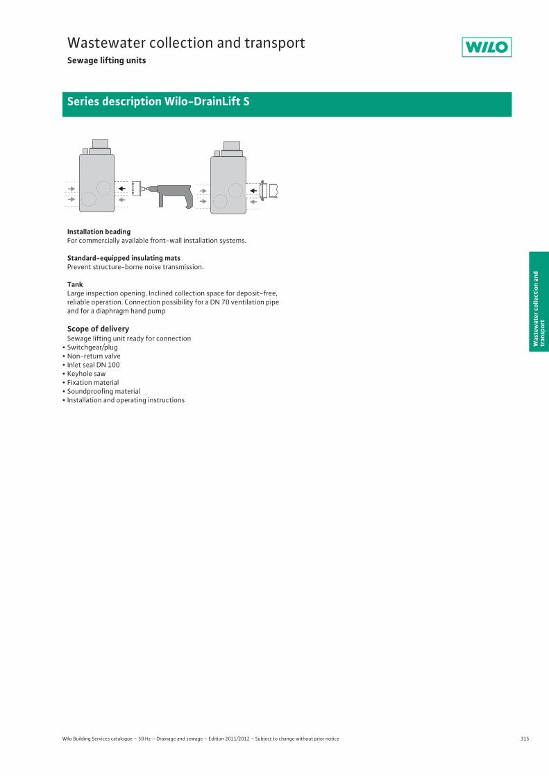
315
Wastewater collection and transportSewage lifting units
Wilo Building Services catalogue – 50 Hz – Drainage and sewage – Edition 2011/2012 – Subject to change without prior notice
Series description Wilo-DrainLift S
Was
tew
ater
col
lect
ion
and
tran
spor
t
Installation beadingFor commercially available front-wall installation systems.
Standard-equipped insulating matsPrevent structure-borne noise transmission.
TankLarge inspection opening. Inclined collection space for deposit-free, reliable operation. Connection possibility for a DN 70 ventilation pipe and for a diaphragm hand pump
Scope of deliverySewage lifting unit ready for connection
• Switchgear/plug• Non-return valve• Inlet seal DN 100• Keyhole saw• Fixation material • Soundproofing material• Installation and operating instructions
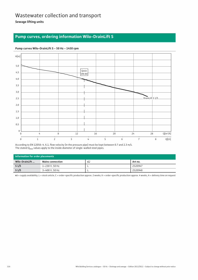
316 Wilo Building Services catalogue – 50 Hz – Drainage and sewage – Edition 2011/2012 – Subject to change without prior notice
Wastewater collection and transportSewage lifting units
Pump curves, ordering information Wilo-DrainLift S
Pump curves Wilo-DrainLift S - 50 Hz - 1450 rpm
According to EN 12056-4, 6.1, flow velocity (in the pressure pipe) must be kept between 0.7 and 2.3 m/s.The stated Qmin values apply to the inside diameter of single-walled steel pipes.
Information for order placements
Wilo-DrainLift ... Mains connection � Art no.S 1/5 1~230 V, 50 Hz L 2520947
S 1/5 3~400 V, 50 Hz L 2520948
�= supply availability, L = stock article, C = order-specific production approx. 2 weeks, K = order-specific production approx. 4 weeks, A = delivery time on request
Q[m³/h]0 4 8 12 16 20 24 28
Q[l/s]0 1 2 3 4 5 6 7 8
H[m]
0
0,5
1,0
1,5
2,0
2,5
3,0
3,5
4,0
4,5
5,0
QminDN 80
DrainLift S 1/5
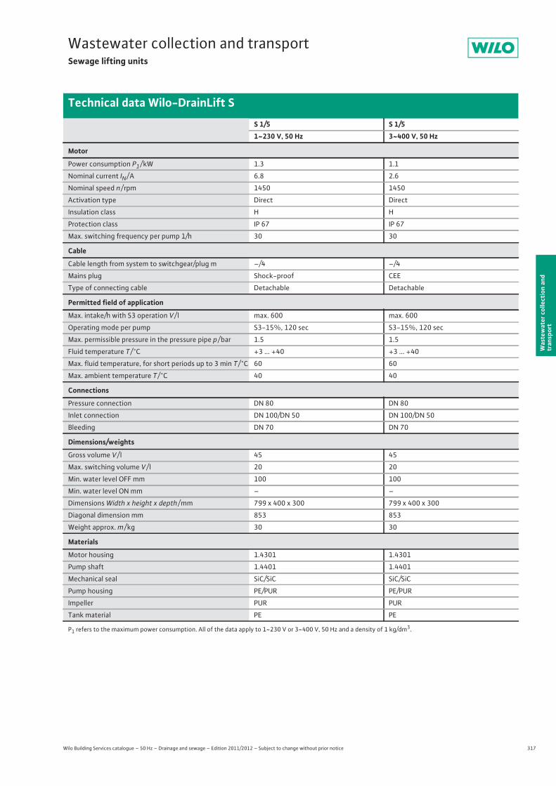
317
Wastewater collection and transportSewage lifting units
Wilo Building Services catalogue – 50 Hz – Drainage and sewage – Edition 2011/2012 – Subject to change without prior notice
Technical data Wilo-DrainLift S
Was
tew
ater
col
lect
ion
and
tran
spor
t
S 1/5 S 1/51~230 V, 50 Hz 3~400 V, 50 Hz
Motor
Power consumption P1 / kW 1.3 1.1
Nominal current IN / A 6.8 2.6
Nominal speed n / rpm 1450 1450
Activation type Direct Direct
Insulation class H H
Protection class IP 67 IP 67
Max. switching frequency per pump 1/h 30 30
Cable
Cable length from system to switchgear/plug m –/4 –/4
Mains plug Shock-proof CEE
Type of connecting cable Detachable Detachable
Permitted field of application
Max. intake/h with S3 operation V / l max. 600 max. 600
Operating mode per pump S3-15%, 120 sec S3-15%, 120 sec
Max. permissible pressure in the pressure pipe p / bar 1.5 1.5
Fluid temperature T / °C +3 ... +40 +3 ... +40
Max. fluid temperature, for short periods up to 3 min T / °C 60 60
Max. ambient temperature T / °C 40 40
Connections
Pressure connection DN 80 DN 80
Inlet connection DN 100/DN 50 DN 100/DN 50
Bleeding DN 70 DN 70
Dimensions/weights
Gross volume V / l 45 45
Max. switching volume V / l 20 20
Min. water level OFF mm 100 100
Min. water level ON mm – –
Dimensions Width x height x depth / mm 799 x 400 x 300 799 x 400 x 300
Diagonal dimension mm 853 853
Weight approx. m / kg 30 30
Materials
Motor housing 1.4301 1.4301
Pump shaft 1.4401 1.4401
Mechanical seal SiC/SiC SiC/SiC
Pump housing PE/PUR PE/PUR
Impeller PUR PUR
Tank material PE PE
P1 refers to the maximum power consumption. All of the data apply to 1~230 V or 3~400 V, 50 Hz and a density of 1 kg/dm3.
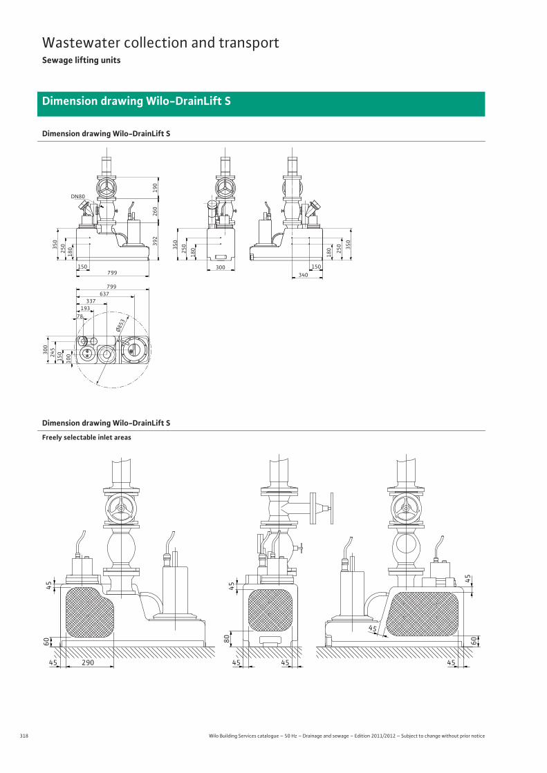
318 Wilo Building Services catalogue – 50 Hz – Drainage and sewage – Edition 2011/2012 – Subject to change without prior notice
Wastewater collection and transportSewage lifting units
Dimension drawing Wilo-DrainLift S
Dimension drawing Wilo-DrainLift S
DN80
350
190
260
392
250
180 350
250
180 35
0
250
180
150 300799
150340
799
Ø853
637337
300
245
150
100
19378
Dimension drawing Wilo-DrainLift S
Freely selectable inlet areas
60
45
45
290 45 45 45
80
4560
45
45
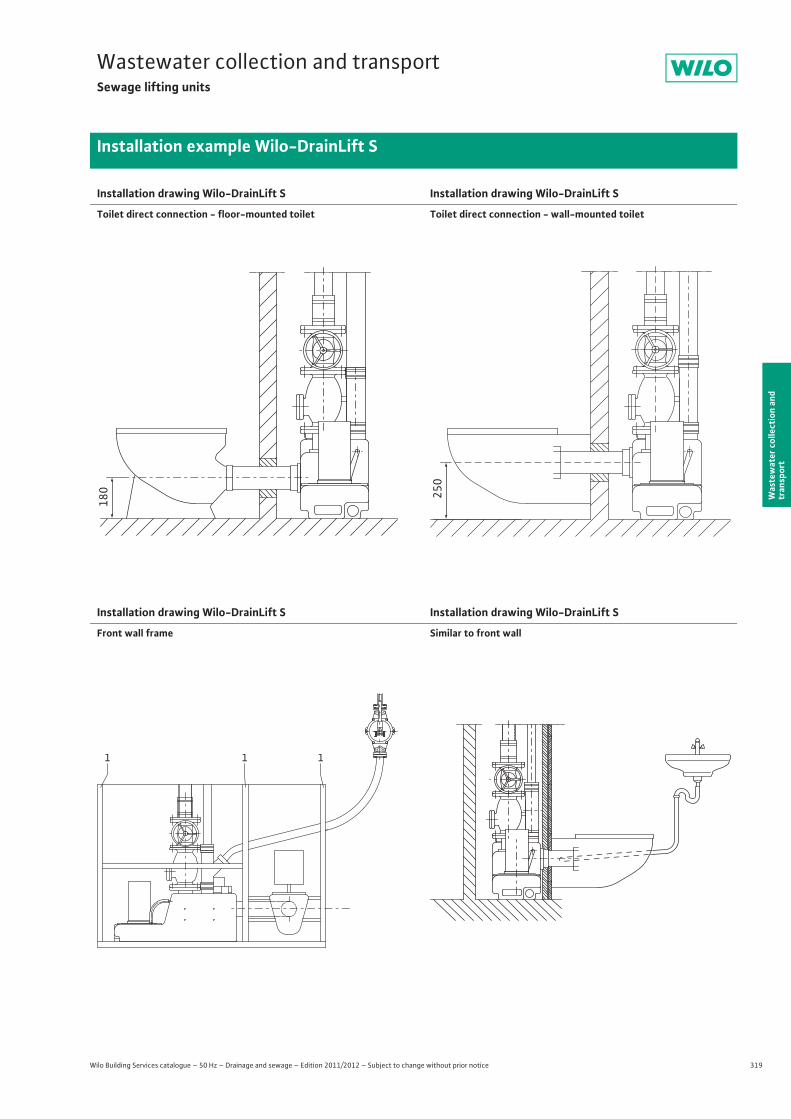
319
Wastewater collection and transportSewage lifting units
Wilo Building Services catalogue – 50 Hz – Drainage and sewage – Edition 2011/2012 – Subject to change without prior notice
Installation example Wilo-DrainLift S
Was
tew
ater
col
lect
ion
and
tran
spor
t
Installation drawing Wilo-DrainLift S
Toilet direct connection - floor-mounted toilet
Installation drawing Wilo-DrainLift S
Toilet direct connection - wall-mounted toilet
Installation drawing Wilo-DrainLift S
Front wall frame
Installation drawing Wilo-DrainLift S
Similar to front wall
180 250
1 1 1
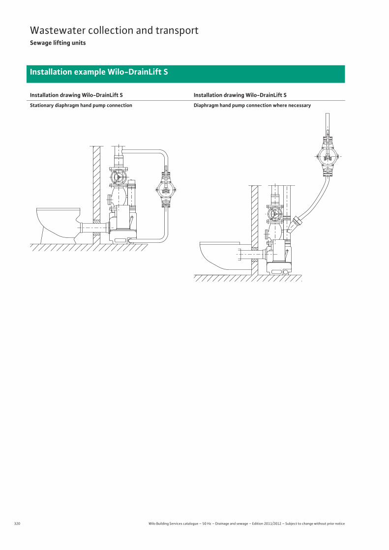
320 Wilo Building Services catalogue – 50 Hz – Drainage and sewage – Edition 2011/2012 – Subject to change without prior notice
Wastewater collection and transportSewage lifting units
Installation example Wilo-DrainLift S
Installation drawing Wilo-DrainLift S
Stationary diaphragm hand pump connection
Installation drawing Wilo-DrainLift S
Diaphragm hand pump connection where necessary
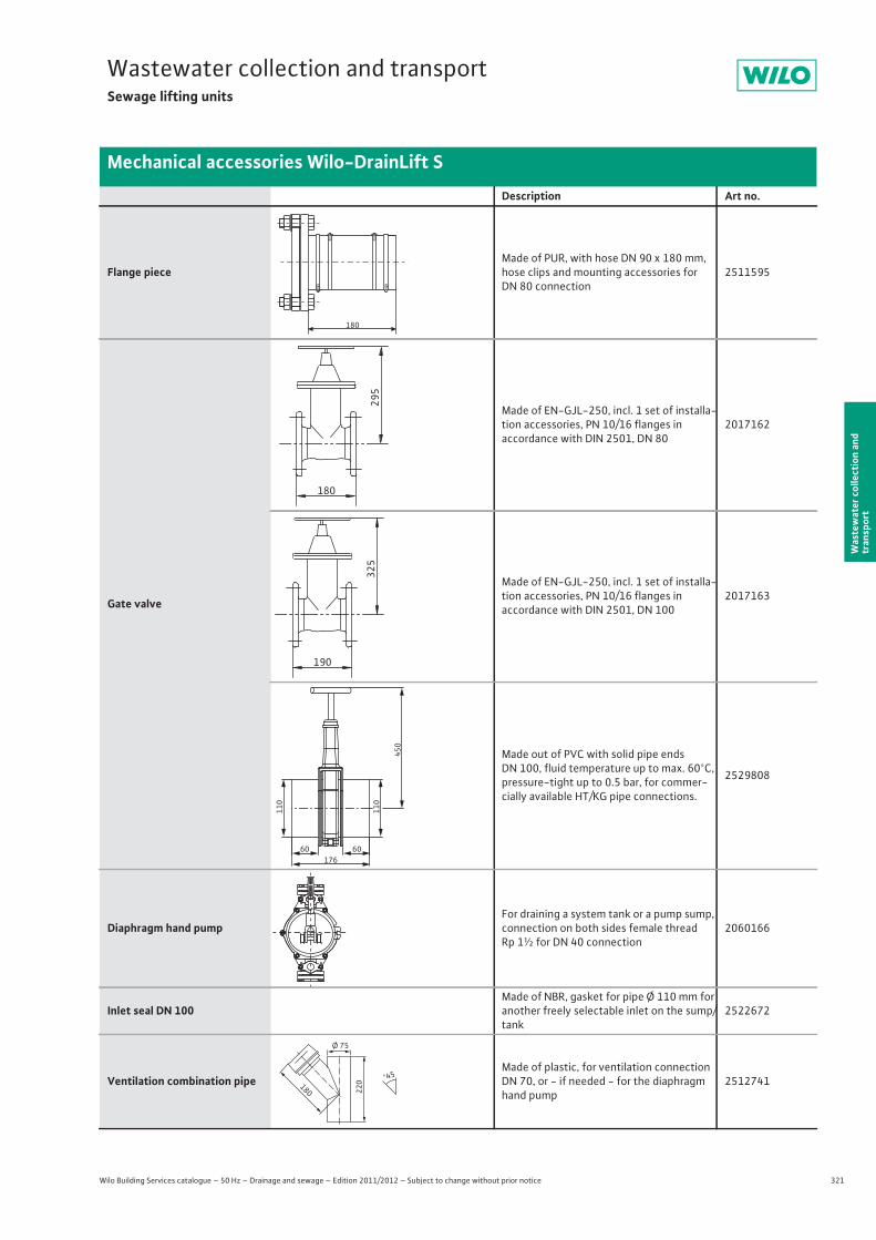
321
Wastewater collection and transportSewage lifting units
Wilo Building Services catalogue – 50 Hz – Drainage and sewage – Edition 2011/2012 – Subject to change without prior notice
Mechanical accessories Wilo-DrainLift S
Was
tew
ater
col
lect
ion
and
tran
spor
t
Description Art no.
Flange pieceMade of PUR, with hose DN 90 x 180 mm, hose clips and mounting accessories for DN 80 connection
2511595
Gate valve
Made of EN-GJL-250, incl. 1 set of installa-tion accessories, PN 10/16 flanges inaccordance with DIN 2501, DN 80
2017162
Made of EN-GJL-250, incl. 1 set of installa-tion accessories, PN 10/16 flanges inaccordance with DIN 2501, DN 100
2017163
Made out of PVC with solid pipe endsDN 100, fluid temperature up to max. 60°C, pressure-tight up to 0.5 bar, for commer-cially available HT/KG pipe connections.
2529808
Diaphragm hand pumpFor draining a system tank or a pump sump, connection on both sides female thread Rp 1½ for DN 40 connection
2060166
Inlet seal DN 100Made of NBR, gasket for pipe Ø 110 mm for another freely selectable inlet on the sump/tank
2522672
Ventilation combination pipeMade of plastic, for ventilation connection DN 70, or - if needed - for the diaphragm hand pump
2512741
180
295
180
325
190
60 60
110
110
450
176
220180
Ø 75
°45
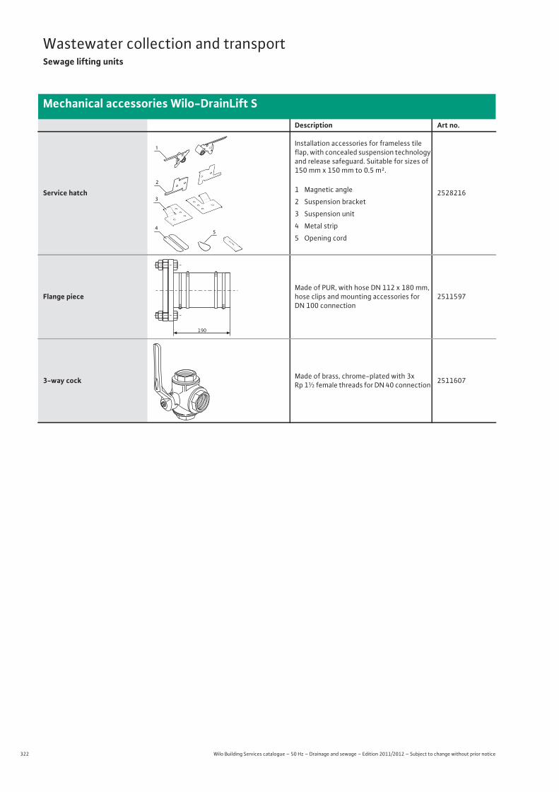
322 Wilo Building Services catalogue – 50 Hz – Drainage and sewage – Edition 2011/2012 – Subject to change without prior notice
Wastewater collection and transportSewage lifting units
Mechanical accessories Wilo-DrainLift S
Service hatch
Installation accessories for frameless tile flap, with concealed suspension technology and release safeguard. Suitable for sizes of 150 mm x 150 mm to 0.5 m².
2528216
Flange pieceMade of PUR, with hose DN 112 x 180 mm, hose clips and mounting accessories for DN 100 connection
2511597
3-way cock Made of brass, chrome-plated with 3x Rp 1½ female threads for DN 40 connection 2511607
Description Art no.
54
1
2
3
1 Magnetic angle
2 Suspension bracket
3 Suspension unit
4 Metal strip
5 Opening cord
190
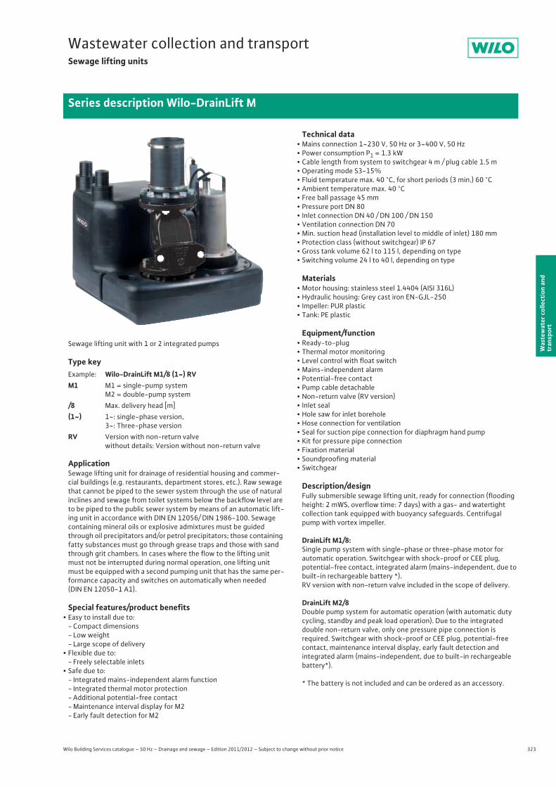
323
Wastewater collection and transportSewage lifting units
Wilo Building Services catalogue – 50 Hz – Drainage and sewage – Edition 2011/2012 – Subject to change without prior notice
Series description Wilo-DrainLift M
Was
tew
ater
col
lect
ion
and
tran
spor
t
Sewage lifting unit with 1 or 2 integrated pumps
Type key
ApplicationSewage lifting unit for drainage of residential housing and commer-cial buildings (e.g. restaurants, department stores, etc.). Raw sewage that cannot be piped to the sewer system through the use of natural inclines and sewage from toilet systems below the backflow level are to be piped to the public sewer system by means of an automatic lift-ing unit in accordance with DIN EN 12056/ DIN 1986-100. Sewage containing mineral oils or explosive admixtures must be guided through oil precipitators and/or petrol precipitators; those containing fatty substances must go through grease traps and those with sand through grit chambers. In cases where the flow to the lifting unit must not be interrupted during normal operation, one lifting unit must be equipped with a second pumping unit that has the same per-formance capacity and switches on automatically when needed (DIN EN 12050-1 A1).
Special features/product benefits• Easy to install due to:
- Compact dimensions- Low weight- Large scope of delivery
• Flexible due to:- Freely selectable inlets
• Safe due to:- Integrated mains-independent alarm function- Integrated thermal motor protection- Additional potential-free contact- Maintenance interval display for M2- Early fault detection for M2
Technical data• Mains connection 1~230 V, 50 Hz or 3~400 V, 50 Hz• Power consumption P1 = 1.3 kW• Cable length from system to switchgear 4 m / plug cable 1.5 m• Operating mode S3-15%• Fluid temperature max. 40 °C, for short periods (3 min.) 60 °C• Ambient temperature max. 40 °C• Free ball passage 45 mm• Pressure port DN 80• Inlet connection DN 40 / DN 100 / DN 150• Ventilation connection DN 70• Min. suction head (installation level to middle of inlet) 180 mm• Protection class (without switchgear) IP 67• Gross tank volume 62 l to 115 l, depending on type• Switching volume 24 l to 40 l, depending on type
Materials• Motor housing: stainless steel 1.4404 (AISI 316L)• Hydraulic housing: Grey cast iron EN-GJL-250• Impeller: PUR plastic• Tank: PE plastic
Equipment/function• Ready-to-plug • Thermal motor monitoring• Level control with float switch• Mains-independent alarm• Potential-free contact• Pump cable detachable• Non-return valve (RV version)• Inlet seal• Hole saw for inlet borehole• Hose connection for ventilation• Seal for suction pipe connection for diaphragm hand pump• Kit for pressure pipe connection• Fixation material• Soundproofing material• Switchgear
Description/designFully submersible sewage lifting unit, ready for connection (flooding height: 2 mWS, overflow time: 7 days) with a gas- and watertight collection tank equipped with buoyancy safeguards. Centrifugal pump with vortex impeller.
DrainLift M1/8:Single pump system with single-phase or three-phase motor forautomatic operation. Switchgear with shock-proof or CEE plug,potential-free contact, integrated alarm (mains-independent, due to built-in rechargeable battery *). RV version with non-return valve included in the scope of delivery.
DrainLift M2/8Double pump system for automatic operation (with automatic duty cycling, standby and peak load operation). Due to the integrated double non-return valve, only one pressure pipe connection isrequired. Switchgear with shock-proof or CEE plug, potential-free contact, maintenance interval display, early fault detection andintegrated alarm (mains-independent, due to built-in rechargeable battery*).
* The battery is not included and can be ordered as an accessory.
Example: Wilo-DrainLift M1/8 (1~) RVM1 M1 = single-pump system
M2 = double-pump system/8 Max. delivery head [m](1~) 1~: single-phase version,
3~: Three-phase versionRV Version with non-return valve
without details: Version without non-return valve
324 Wilo Building Services catalogue – 50 Hz – Drainage and sewage – Edition 2011/2012 – Subject to change without prior notice
Wastewater collection and transportSewage lifting units
Series description Wilo-DrainLift M
Scope of deliveryConnection-ready sewage lifting unit, including:
• Switchgear (mains-independent alarm)• Inlet seal, DN 100 (for pipe Ø 110 mm)• Keyhole saw Ø 124 for inlet, DN 100• PVC hose section Ø 50 mm with clamps for inlet connection, DN 50• Special lip seal for pipe connection, diaphragm hand pump DN 50• Collar for ventilation connection, DN 70• Fixation material• Sound absorption strip for insulation of structure-borne noise• DN 80/100 flange piece with flat gasket, flexible hose section, hose
clips, screws and nuts for connecting the pressure pipeline, DN 100• Non-return valve (RV version)• Installation and operating instructions
OptionsMains-independent alarm utilising 9V block battery (accessories), which is plugged into the switchgear board separately
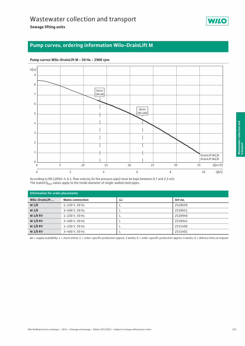
325
Wastewater collection and transportSewage lifting units
Wilo Building Services catalogue – 50 Hz – Drainage and sewage – Edition 2011/2012 – Subject to change without prior notice
Pump curves, ordering information Wilo-DrainLift M
Was
tew
ater
col
lect
ion
and
tran
spor
t
Pump curves Wilo-DrainLift M - 50 Hz - 2900 rpm
According to EN 12056-4, 6.1, flow velocity (in the pressure pipe) must be kept between 0.7 and 2.3 m/s.The stated Qmin values apply to the inside diameter of single-walled steel pipes.
Information for order placements
Wilo-DrainLift ... Mains connection � Art no.M 1/8 1~230 V, 50 Hz L 2528650
M 1/8 3~400 V, 50 Hz L 2528651
M 1/8 RV 1~230 V, 50 Hz L 2528940
M 1/8 RV 3~400 V, 50 Hz L 2528941
M 2/8 RV 1~230 V, 50 Hz L 2531400
M 2/8 RV 3~400 V, 50 Hz L 2531401
�= supply availability, L = stock article, C = order-specific production approx. 2 weeks, K = order-specific production approx. 4 weeks, A = delivery time on request
DrainLift M1/8DrainLift M2/8
Q[m³/h]0 5 10 15 20 25 30 35
Q[l/s]0 2 4 6 8 10
H[m]
0
1
2
3
4
5
6
7
8
9
QminDN 80
QminDN 100
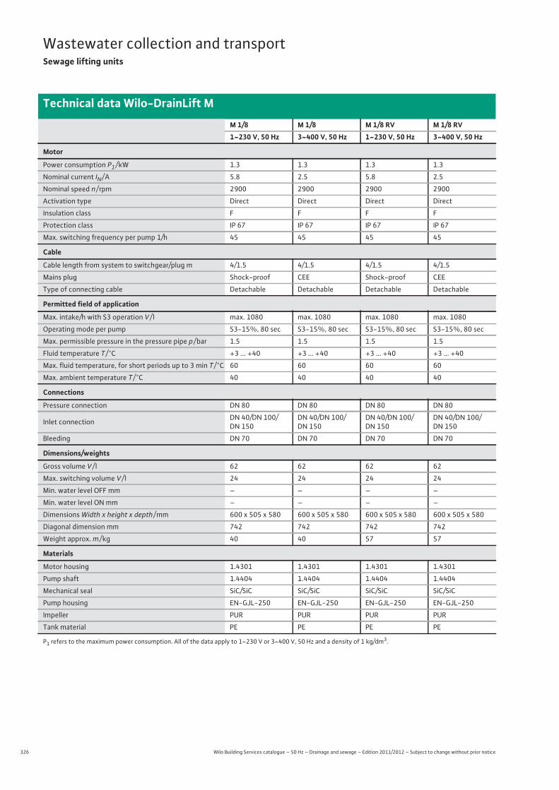
326 Wilo Building Services catalogue – 50 Hz – Drainage and sewage – Edition 2011/2012 – Subject to change without prior notice
Wastewater collection and transportSewage lifting units
Technical data Wilo-DrainLift M
M 1/8 M 1/8 M 1/8 RV M 1/8 RV1~230 V, 50 Hz 3~400 V, 50 Hz 1~230 V, 50 Hz 3~400 V, 50 Hz
Motor
Power consumption P1 / kW 1.3 1.3 1.3 1.3
Nominal current IN / A 5.8 2.5 5.8 2.5
Nominal speed n / rpm 2900 2900 2900 2900
Activation type Direct Direct Direct Direct
Insulation class F F F F
Protection class IP 67 IP 67 IP 67 IP 67
Max. switching frequency per pump 1/h 45 45 45 45
Cable
Cable length from system to switchgear/plug m 4/1.5 4/1.5 4/1.5 4/1.5
Mains plug Shock-proof CEE Shock-proof CEE
Type of connecting cable Detachable Detachable Detachable Detachable
Permitted field of application
Max. intake/h with S3 operation V / l max. 1080 max. 1080 max. 1080 max. 1080
Operating mode per pump S3-15%, 80 sec S3-15%, 80 sec S3-15%, 80 sec S3-15%, 80 sec
Max. permissible pressure in the pressure pipe p / bar 1.5 1.5 1.5 1.5
Fluid temperature T / °C +3 ... +40 +3 ... +40 +3 ... +40 +3 ... +40
Max. fluid temperature, for short periods up to 3 min T / °C 60 60 60 60
Max. ambient temperature T / °C 40 40 40 40
Connections
Pressure connection DN 80 DN 80 DN 80 DN 80
Inlet connection DN 40/DN 100/DN 150
DN 40/DN 100/DN 150
DN 40/DN 100/DN 150
DN 40/DN 100/DN 150
Bleeding DN 70 DN 70 DN 70 DN 70
Dimensions/weights
Gross volume V / l 62 62 62 62
Max. switching volume V / l 24 24 24 24
Min. water level OFF mm – – – –
Min. water level ON mm – – – –
Dimensions Width x height x depth / mm 600 x 505 x 580 600 x 505 x 580 600 x 505 x 580 600 x 505 x 580
Diagonal dimension mm 742 742 742 742
Weight approx. m / kg 40 40 57 57
Materials
Motor housing 1.4301 1.4301 1.4301 1.4301
Pump shaft 1.4404 1.4404 1.4404 1.4404
Mechanical seal SiC/SiC SiC/SiC SiC/SiC SiC/SiC
Pump housing EN-GJL-250 EN-GJL-250 EN-GJL-250 EN-GJL-250
Impeller PUR PUR PUR PUR
Tank material PE PE PE PE
P1 refers to the maximum power consumption. All of the data apply to 1~230 V or 3~400 V, 50 Hz and a density of 1 kg/dm3.

327
Wastewater collection and transportSewage lifting units
Wilo Building Services catalogue – 50 Hz – Drainage and sewage – Edition 2011/2012 – Subject to change without prior notice
Technical data Wilo-DrainLift M
Was
tew
ater
col
lect
ion
and
tran
spor
t
M 2/8 RV M 2/8 RV1~230 V, 50 Hz 3~400 V, 50 Hz
Motor
Power consumption P1 / kW 2x 1.3 2x 1.3
Nominal current IN / A 2x 5.8 2x 2.5
Nominal speed n / rpm 2900 2900
Activation type Direct Direct
Insulation class F F
Protection class IP 67 IP 67
Max. switching frequency per pump 1/h 45 45
Cable
Cable length from system to switchgear/plug m 4/1.5 4/1.5
Mains plug Shock-proof CEE
Type of connecting cable Detachable Detachable
Permitted field of application
Max. intake/h with S3 operation V / l max. 3600 max. 3600
Operating mode per pump S3-15%, 80 sec S3-15%, 80 sec
Max. permissible pressure in the pressure pipe p / bar 1.5 1.5
Fluid temperature T / °C +3 ... +40 +3 ... +40
Max. fluid temperature, for short periods up to 3 min T / °C 60 60
Max. ambient temperature T / °C 40 40
Connections
Pressure connection DN 80 DN 80
Inlet connection DN 40/DN 100/DN 150 DN 40/DN 100/DN 150
Bleeding DN 70 DN 70
Dimensions/weights
Gross volume V / l 115 115
Max. switching volume V / l 40 40
Min. water level OFF mm – –
Min. water level ON mm – –
Dimensions Width x height x depth / mm 810 x 505 x 780 810 x 505 x 780
Diagonal dimension mm 970 970
Weight approx. m / kg 91 91
Materials
Motor housing 1.4301 1.4301
Pump shaft 1.4404 1.4404
Mechanical seal SiC/SiC SiC/SiC
Pump housing EN-GJL-250 EN-GJL-250
Impeller PUR PUR
Tank material PE PE
P1 refers to the maximum power consumption. All of the data apply to 1~230 V or 3~400 V, 50 Hz and a density of 1 kg/dm3.
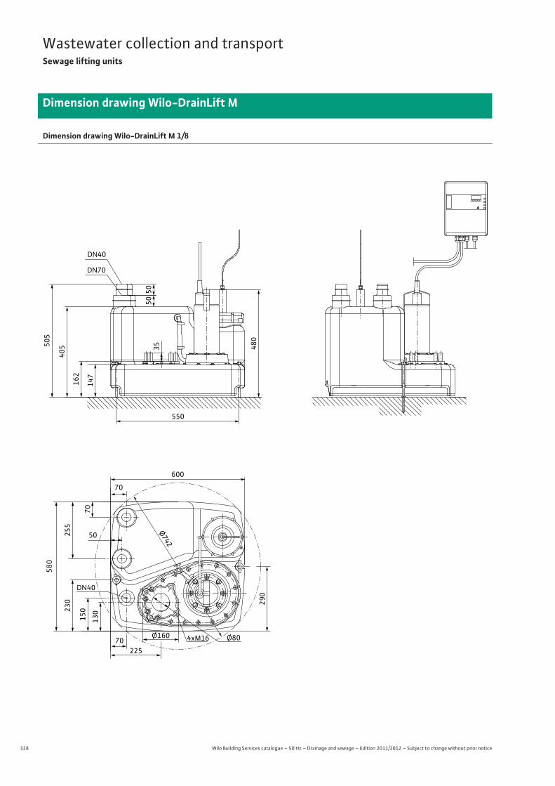
328 Wilo Building Services catalogue – 50 Hz – Drainage and sewage – Edition 2011/2012 – Subject to change without prior notice
Wastewater collection and transportSewage lifting units
Dimension drawing Wilo-DrainLift M
Dimension drawing Wilo-DrainLift M 1/8
550
600
Ø742
70
70
255
580
230
150
130
290
50
Ø804xM16Ø16070
225
DN40
DN40
DN70
505
405
162
147
35 480
5050
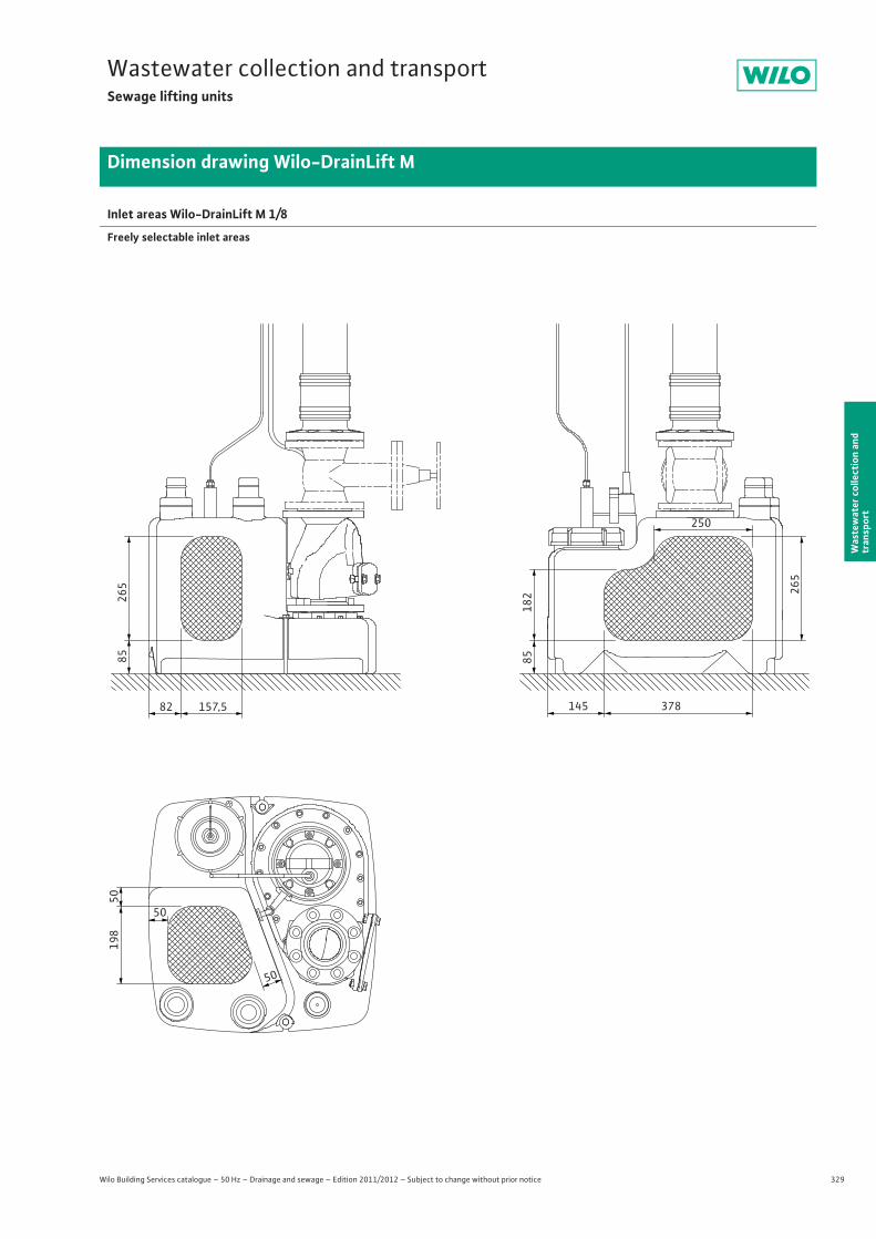
329
Wastewater collection and transportSewage lifting units
Wilo Building Services catalogue – 50 Hz – Drainage and sewage – Edition 2011/2012 – Subject to change without prior notice
Dimension drawing Wilo-DrainLift M
Was
tew
ater
col
lect
ion
and
tran
spor
t
Inlet areas Wilo-DrainLift M 1/8
Freely selectable inlet areas
82 157,5
85265
145 378
85182 26
5
250
50
50
50
198
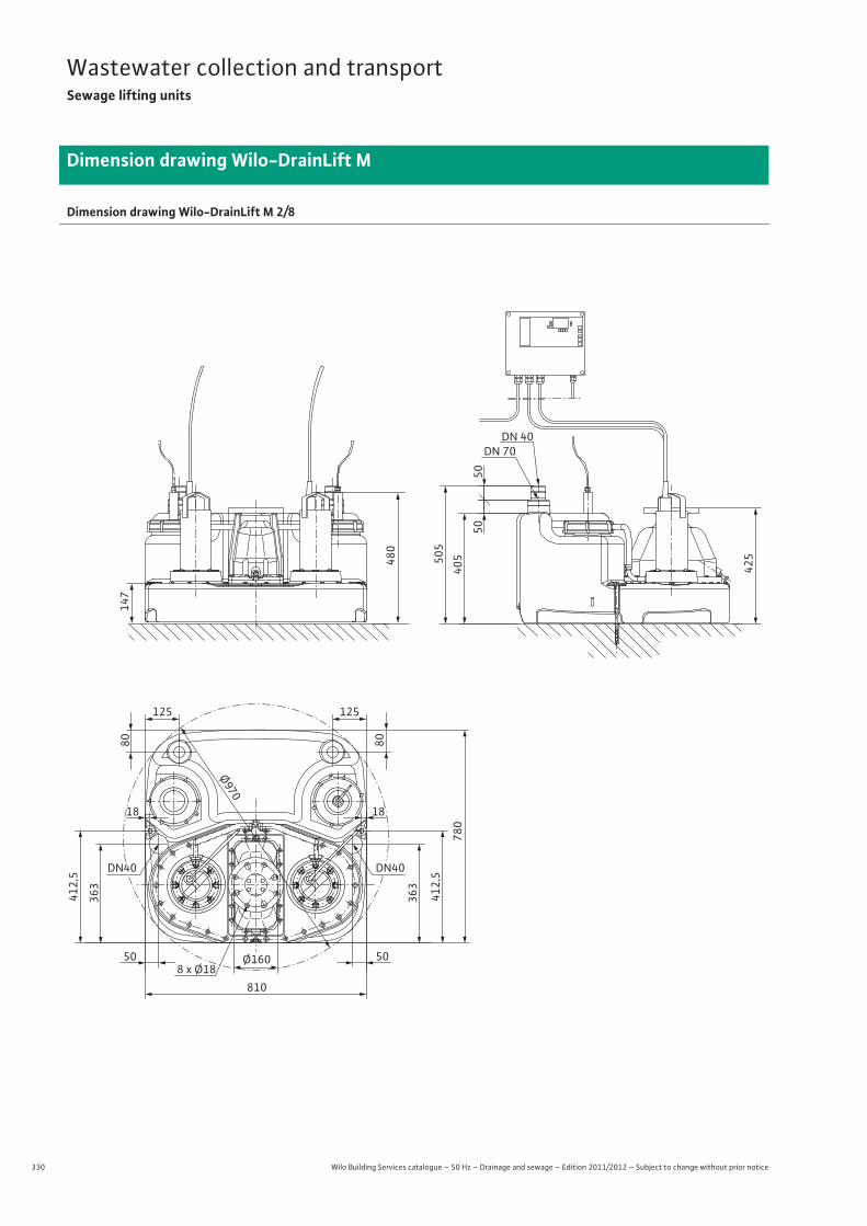
330 Wilo Building Services catalogue – 50 Hz – Drainage and sewage – Edition 2011/2012 – Subject to change without prior notice
Wastewater collection and transportSewage lifting units
Dimension drawing Wilo-DrainLift M
Dimension drawing Wilo-DrainLift M 2/8
480
425505
405
5050
DN 40DN 70
147
125
Ø970
125
508 x Ø18
Ø16050
810
18 18
DN40
363
412,5
363
412,5
780
DN40
8080
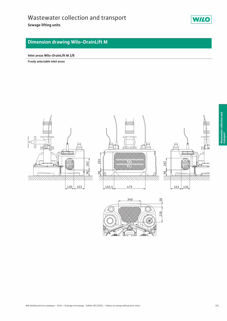
331
Wastewater collection and transportSewage lifting units
Wilo Building Services catalogue – 50 Hz – Drainage and sewage – Edition 2011/2012 – Subject to change without prior notice
Dimension drawing Wilo-DrainLift M
Was
tew
ater
col
lect
ion
and
tran
spor
t
Inlet areas Wilo-DrainLift M 2/8
Freely selectable inlet areas
182
90
265
90
182
90
130163163130 479
340
230
50
245,5
165,5
250180
250180
250180
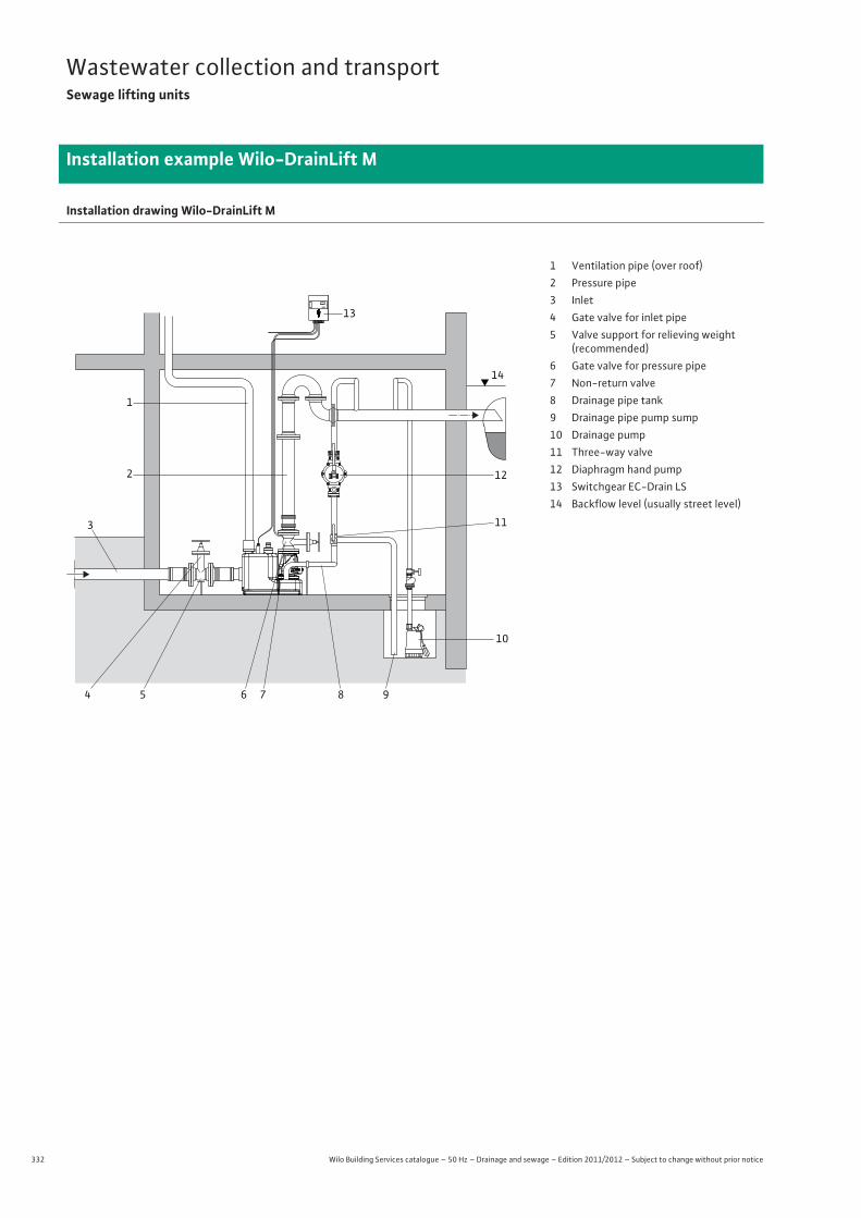
332 Wilo Building Services catalogue – 50 Hz – Drainage and sewage – Edition 2011/2012 – Subject to change without prior notice
Wastewater collection and transportSewage lifting units
Installation example Wilo-DrainLift M
Installation drawing Wilo-DrainLift M
13
14
12
10
98765
3
4
2
1
11
1 Ventilation pipe (over roof)2 Pressure pipe3 Inlet4 Gate valve for inlet pipe5 Valve support for relieving weight
(recommended)6 Gate valve for pressure pipe7 Non-return valve8 Drainage pipe tank9 Drainage pipe pump sump10 Drainage pump11 Three-way valve12 Diaphragm hand pump13 Switchgear EC-Drain LS14 Backflow level (usually street level)

333
Wastewater collection and transportSewage lifting units
Wilo Building Services catalogue – 50 Hz – Drainage and sewage – Edition 2011/2012 – Subject to change without prior notice
Mechanical accessories Wilo-DrainLift M
Was
tew
ater
col
lect
ion
and
tran
spor
t
Description Art no.
Gate valve
Made of EN-GJL-250, incl. 1 set of installa-tion accessories, PN 10/16 flanges inaccordance with DIN 2501, DN 80
2017162
Made of EN-GJL-250, incl. 1 set of installa-tion accessories, PN 10/16 flanges inaccordance with DIN 2501, DN 100
2017163
Made of EN-GJL-250, incl. 1 set of installa-tion accessories, PN 10/16 flanges inaccordance with DIN 2501, DN 150
2017164
Made out of PVC with solid pipe ends DN 100, fluid temperature up to max. 60°C, pressure-tight up to 0.5 bar, for commercially available HT/KG pipe connections.
2529808
Made of PVC with solid pipe ends DN 150, flu-id temperature up to max. 60°C, pressure-tight up to 0.5 bar, for commercially available HT/KG pipe connections.
2529809
295
180
325
190
210
285
60 60
110
110
450
176
60 60
150
150
650
227
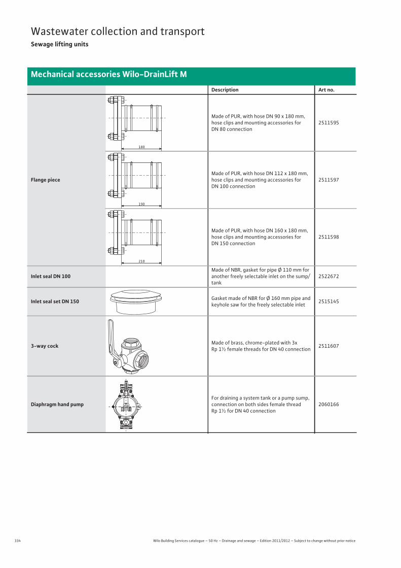
334 Wilo Building Services catalogue – 50 Hz – Drainage and sewage – Edition 2011/2012 – Subject to change without prior notice
Wastewater collection and transportSewage lifting units
Mechanical accessories Wilo-DrainLift M
Flange piece
Made of PUR, with hose DN 90 x 180 mm, hose clips and mounting accessories forDN 80 connection
2511595
Made of PUR, with hose DN 112 x 180 mm, hose clips and mounting accessories for DN 100 connection
2511597
Made of PUR, with hose DN 160 x 180 mm, hose clips and mounting accessories for DN 150 connection
2511598
Inlet seal DN 100Made of NBR, gasket for pipe Ø 110 mm for another freely selectable inlet on the sump/tank
2522672
Inlet seal set DN 150 Gasket made of NBR for Ø 160 mm pipe and keyhole saw for the freely selectable inlet 2515145
3-way cock Made of brass, chrome-plated with 3x Rp 1½ female threads for DN 40 connection 2511607
Diaphragm hand pumpFor draining a system tank or a pump sump, connection on both sides female thread Rp 1½ for DN 40 connection
2060166
Description Art no.
180
190
210
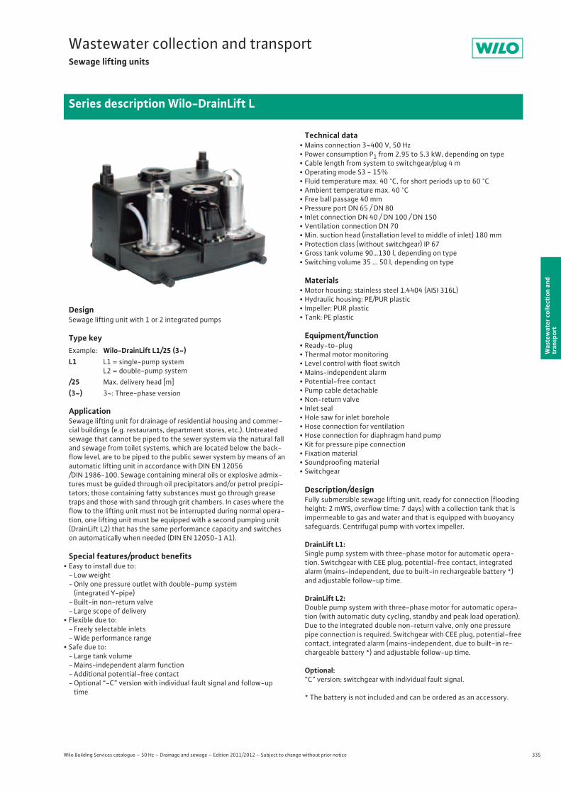
335
Wastewater collection and transportSewage lifting units
Wilo Building Services catalogue – 50 Hz – Drainage and sewage – Edition 2011/2012 – Subject to change without prior notice
Series description Wilo-DrainLift L
Was
tew
ater
col
lect
ion
and
tran
spor
t
DesignSewage lifting unit with 1 or 2 integrated pumps
Type key
ApplicationSewage lifting unit for drainage of residential housing and commer-cial buildings (e.g. restaurants, department stores, etc.). Untreated sewage that cannot be piped to the sewer system via the natural fall and sewage from toilet systems, which are located below the back-flow level, are to be piped to the public sewer system by means of an automatic lifting unit in accordance with DIN EN 12056/DIN 1986-100. Sewage containing mineral oils or explosive admix-tures must be guided through oil precipitators and/or petrol precipi-tators; those containing fatty substances must go through grease traps and those with sand through grit chambers. In cases where the flow to the lifting unit must not be interrupted during normal opera-tion, one lifting unit must be equipped with a second pumping unit (DrainLift L2) that has the same performance capacity and switches on automatically when needed (DIN EN 12050-1 A1).
Special features/product benefits• Easy to install due to:
- Low weight- Only one pressure outlet with double-pump system
(integrated Y-pipe)- Built-in non-return valve- Large scope of delivery
• Flexible due to:- Freely selectable inlets- Wide performance range
• Safe due to:- Large tank volume- Mains-independent alarm function- Additional potential-free contact - Optional “-C” version with individual fault signal and follow-up
time
Technical data• Mains connection 3~400 V, 50 Hz• Power consumption P1 from 2.95 to 5.3 kW, depending on type• Cable length from system to switchgear/plug 4 m• Operating mode S3 - 15%• Fluid temperature max. 40 °C, for short periods up to 60 °C• Ambient temperature max. 40 °C• Free ball passage 40 mm• Pressure port DN 65 / DN 80• Inlet connection DN 40 / DN 100 / DN 150• Ventilation connection DN 70• Min. suction head (installation level to middle of inlet) 180 mm• Protection class (without switchgear) IP 67• Gross tank volume 90…130 l, depending on type• Switching volume 35 … 50 l, depending on type
Materials• Motor housing: stainless steel 1.4404 (AISI 316L)• Hydraulic housing: PE/PUR plastic• Impeller: PUR plastic• Tank: PE plastic
Equipment/function• Ready-to-plug • Thermal motor monitoring• Level control with float switch• Mains-independent alarm• Potential-free contact• Pump cable detachable• Non-return valve • Inlet seal• Hole saw for inlet borehole• Hose connection for ventilation• Hose connection for diaphragm hand pump• Kit for pressure pipe connection• Fixation material• Soundproofing material• Switchgear
Description/designFully submersible sewage lifting unit, ready for connection (flooding height: 2 mWS, overflow time: 7 days) with a collection tank that is impermeable to gas and water and that is equipped with buoyancy safeguards. Centrifugal pump with vortex impeller.
DrainLift L1:Single pump system with three-phase motor for automatic opera-tion. Switchgear with CEE plug, potential-free contact, integrated alarm (mains-independent, due to built-in rechargeable battery *) and adjustable follow-up time.
DrainLift L2:Double pump system with three-phase motor for automatic opera-tion (with automatic duty cycling, standby and peak load operation). Due to the integrated double non-return valve, only one pressure pipe connection is required. Switchgear with CEE plug, potential-free contact, integrated alarm (mains-independent, due to built-in re-chargeable battery *) and adjustable follow-up time.
Optional:“C” version: switchgear with individual fault signal.
* The battery is not included and can be ordered as an accessory.
Example: Wilo-DrainLift L1/25 (3~)L1 L1 = single-pump system
L2 = double-pump system/25 Max. delivery head [m](3~) 3~: Three-phase version

336 Wilo Building Services catalogue – 50 Hz – Drainage and sewage – Edition 2011/2012 – Subject to change without prior notice
Wastewater collection and transportSewage lifting units
Series description Wilo-DrainLift L
Scope of deliverySewage lifting unit, ready for connection, including:
• Switchgear (mains-independent alarm)• Inlet seal DN100 (for pipe Ø 110 mm)• Keyhole saw Ø124 for inlet DN100• PVC hose section Ø 50 mm with clamps for inlet connection DN50• Hose section DN50 with hose clips for pipe connection of diaphragm
hand pump or an inlet DN40• Sleeve for ventilation connection DN70• Fixation material • Sound absorption strip for insulation of structure-borne noise• Flange piece DN80/100 with flat gasket, flexible hose section, hose
clips, screws and nuts for connection of pressure pipeline DN100• Installation and operating instructions
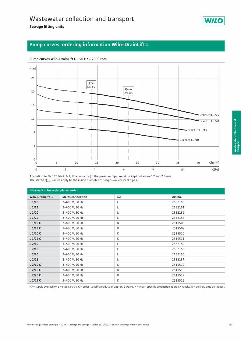
337
Wastewater collection and transportSewage lifting units
Wilo Building Services catalogue – 50 Hz – Drainage and sewage – Edition 2011/2012 – Subject to change without prior notice
Pump curves, ordering information Wilo-DrainLift L
Was
tew
ater
col
lect
ion
and
tran
spor
t
Pump curves Wilo-DrainLift L - 50 Hz - 2900 rpm
According to EN 12056-4, 6.1, flow velocity (in the pressure pipe) must be kept between 0.7 and 2.3 m/s.The stated Qmin values apply to the inside diameter of single-walled steel pipes.
Information for order placements
Wilo-DrainLift ... Mains connection � Art no.L 1/10 3~400 V, 50 Hz L 2532150
L 1/15 3~400 V, 50 Hz L 2532151
L 1/20 3~400 V, 50 Hz L 2532152
L 1/25 3~400 V, 50 Hz L 2532153
L 1/10 C 3~400 V, 50 Hz K 2519508
L 1/15 C 3~400 V, 50 Hz K 2519509
L 1/20 C 3~400 V, 50 Hz K 2519510
L 1/25 C 3~400 V, 50 Hz K 2519511
L 2/10 3~400 V, 50 Hz L 2532154
L 2/15 3~400 V, 50 Hz L 2532155
L 2/20 3~400 V, 50 Hz L 2532156
L 2/25 3~400 V, 50 Hz L 2532157
L 2/10 C 3~400 V, 50 Hz K 2519512
L 2/15 C 3~400 V, 50 Hz K 2519513
L 2/20 C 3~400 V, 50 Hz K 2519514
L 2/25 C 3~400 V, 50 Hz K 2519515
�= supply availability, L = stock article, C = order-specific production approx. 2 weeks, K = order-specific production approx. 4 weeks, A = delivery time on request
DrainLift L.../10
DrainLift L.../25
DrainLift L.../20
Q[m³/h]0 5 10 15 20 25 30 35 40
Q[l/s]0 2 4 6 8 10
H[m]
0
4
8
12
16
20
24
QminDN 80
QminDN 100
DrainLift L.../15

338 Wilo Building Services catalogue – 50 Hz – Drainage and sewage – Edition 2011/2012 – Subject to change without prior notice
Wastewater collection and transportSewage lifting units
Technical data Wilo-DrainLift L
L 1/10 L 1/15 L 1/20 L 1/253~400 V, 50 Hz 3~400 V, 50 Hz 3~400 V, 50 Hz 3~400 V, 50 Hz
Motor
Power consumption P1 / kW 3.0 3.8 4.9 5.3
Nominal current IN / A 6.0 6.9 8.5 8.9
Nominal speed n / rpm 2900 2900 2900 2900
Activation type Direct Direct Direct Direct
Insulation class H H H H
Protection class IP 67 IP 67 IP 67 IP 67
Max. switching frequency per pump 1/h 30 30 30 30
Cable
Cable length from system to switchgear/plug m 4/1.5 4/1.5 4/1.5 4/1.5
Mains plug CEE CEE CEE CEE
Type of connecting cable Detachable Detachable Detachable Detachable
Permitted field of application
Max. intake/h with S3 operation V / l max. 1050 max. 1050 max. 1050 max. 1050
Operating mode per pump S3-15%, 120 sec S3-15%, 120 sec S3-15%, 120 sec S3-15%, 120 sec
Max. permissible pressure in the pressure pipe p / bar 3 3 3 3
Fluid temperature T / °C +3 ... +40 +3 ... +40 +3 ... +40 +3 ... +40
Max. fluid temperature, for short periods up to 3 min T / °C 60 60 60 60
Max. ambient temperature T / °C 40 40 40 40
Connections
Pressure connection DN 80 DN 80 DN 80 DN 80
Inlet connection DN 50/DN 100/DN 150
DN 50/DN 100/DN 150
DN 50/DN 100/DN 150
DN 50/DN 100/DN 150
Bleeding DN 70 DN 70 DN 70 DN 70
Dimensions/weights
Gross volume V / l 115 115 115 115
Max. switching volume V / l 35 35 35 35
Min. water level OFF mm 90 90 90 90
Min. water level ON mm – – – –
Dimensions Width x height x depth / mm 630 x 770 x 630 630 x 770 x 630 630 x 770 x 630 630 x 770 x 630
Diagonal dimension mm 994 994 994 994
Weight approx. m / kg 55 55 55 55
Materials
Motor housing 1.4404 1.4404 1.4404 1.4404
Pump shaft 1.4404 1.4404 1.4404 1.4404
Mechanical seal SiC/SiC SiC/SiC SiC/SiC SiC/SiC
Pump housing PE/PUR PE/PUR PE/PUR PE/PUR
Impeller PUR PUR PUR PUR
Tank material PE PE PE PE
P1 refers to the maximum power consumption. All of the data applies to 3~400 V, 50 Hz and a density of 1 kg/dm3.
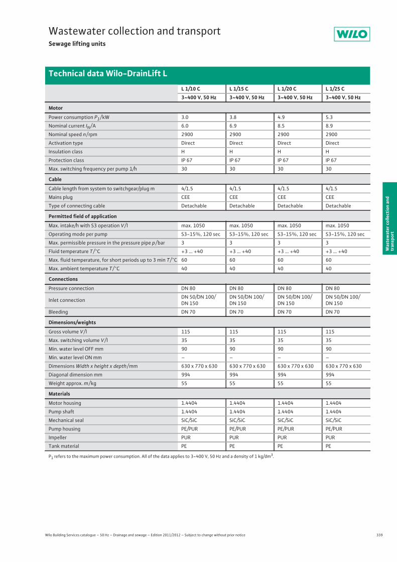
339
Wastewater collection and transportSewage lifting units
Wilo Building Services catalogue – 50 Hz – Drainage and sewage – Edition 2011/2012 – Subject to change without prior notice
Technical data Wilo-DrainLift L
Was
tew
ater
col
lect
ion
and
tran
spor
t
L 1/10 C L 1/15 C L 1/20 C L 1/25 C3~400 V, 50 Hz 3~400 V, 50 Hz 3~400 V, 50 Hz 3~400 V, 50 Hz
Motor
Power consumption P1 / kW 3.0 3.8 4.9 5.3
Nominal current IN / A 6.0 6.9 8.5 8.9
Nominal speed n / rpm 2900 2900 2900 2900
Activation type Direct Direct Direct Direct
Insulation class H H H H
Protection class IP 67 IP 67 IP 67 IP 67
Max. switching frequency per pump 1/h 30 30 30 30
Cable
Cable length from system to switchgear/plug m 4/1.5 4/1.5 4/1.5 4/1.5
Mains plug CEE CEE CEE CEE
Type of connecting cable Detachable Detachable Detachable Detachable
Permitted field of application
Max. intake/h with S3 operation V / l max. 1050 max. 1050 max. 1050 max. 1050
Operating mode per pump S3-15%, 120 sec S3-15%, 120 sec S3-15%, 120 sec S3-15%, 120 sec
Max. permissible pressure in the pressure pipe p / bar 3 3 3 3
Fluid temperature T / °C +3 ... +40 +3 ... +40 +3 ... +40 +3 ... +40
Max. fluid temperature, for short periods up to 3 min T / °C 60 60 60 60
Max. ambient temperature T / °C 40 40 40 40
Connections
Pressure connection DN 80 DN 80 DN 80 DN 80
Inlet connection DN 50/DN 100/DN 150
DN 50/DN 100/DN 150
DN 50/DN 100/DN 150
DN 50/DN 100/DN 150
Bleeding DN 70 DN 70 DN 70 DN 70
Dimensions/weights
Gross volume V / l 115 115 115 115
Max. switching volume V / l 35 35 35 35
Min. water level OFF mm 90 90 90 90
Min. water level ON mm – – – –
Dimensions Width x height x depth / mm 630 x 770 x 630 630 x 770 x 630 630 x 770 x 630 630 x 770 x 630
Diagonal dimension mm 994 994 994 994
Weight approx. m / kg 55 55 55 55
Materials
Motor housing 1.4404 1.4404 1.4404 1.4404
Pump shaft 1.4404 1.4404 1.4404 1.4404
Mechanical seal SiC/SiC SiC/SiC SiC/SiC SiC/SiC
Pump housing PE/PUR PE/PUR PE/PUR PE/PUR
Impeller PUR PUR PUR PUR
Tank material PE PE PE PE
P1 refers to the maximum power consumption. All of the data applies to 3~400 V, 50 Hz and a density of 1 kg/dm3.
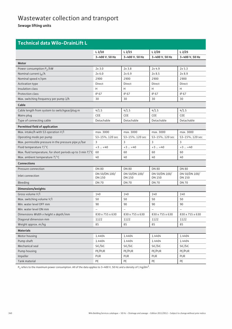
340 Wilo Building Services catalogue – 50 Hz – Drainage and sewage – Edition 2011/2012 – Subject to change without prior notice
Wastewater collection and transportSewage lifting units
Technical data Wilo-DrainLift L
L 2/10 L 2/15 L 2/20 L 2/253~400 V, 50 Hz 3~400 V, 50 Hz 3~400 V, 50 Hz 3~400 V, 50 Hz
Motor
Power consumption P1 / kW 2x 3.0 2x 3.8 2x 4.9 2x 5.3
Nominal current IN / A 2x 6.0 2x 6.9 2x 8.5 2x 8.9
Nominal speed n / rpm 2900 2900 2900 2900
Activation type Direct Direct Direct Direct
Insulation class H H H H
Protection class IP 67 IP 67 IP 67 IP 67
Max. switching frequency per pump 1/h 30 30 30 30
Cable
Cable length from system to switchgear/plug m 4/1.5 4/1.5 4/1.5 4/1.5
Mains plug CEE CEE CEE CEE
Type of connecting cable Detachable Detachable Detachable Detachable
Permitted field of application
Max. intake/h with S3 operation V / l max. 3000 max. 3000 max. 3000 max. 3000
Operating mode per pump S3-15%, 120 sec S3-15%, 120 sec S3-15%, 120 sec S3-15%, 120 sec
Max. permissible pressure in the pressure pipe p / bar 3 3 3 3
Fluid temperature T / °C +3 ... +40 +3 ... +40 +3 ... +40 +3 ... +40
Max. fluid temperature, for short periods up to 3 min T / °C 60 60 60 60
Max. ambient temperature T / °C 40 40 40 40
Connections
Pressure connection DN 80 DN 80 DN 80 DN 80
Inlet connection DN 50/DN 100/DN 150
DN 50/DN 100/DN 150
DN 50/DN 100/DN 150
DN 50/DN 100/DN 150
Bleeding DN 70 DN 70 DN 70 DN 70
Dimensions/weights
Gross volume V / l 140 140 140 140
Max. switching volume V / l 50 50 50 50
Min. water level OFF mm 90 90 90 90
Min. water level ON mm – – – –
Dimensions Width x height x depth / mm 830 x 755 x 630 830 x 755 x 630 830 x 755 x 630 830 x 755 x 630
Diagonal dimension mm 1122 1122 1122 1122
Weight approx. m / kg 85 85 85 85
Materials
Motor housing 1.4404 1.4404 1.4404 1.4404
Pump shaft 1.4404 1.4404 1.4404 1.4404
Mechanical seal SiC/SiC SiC/SiC SiC/SiC SiC/SiC
Pump housing PE/PUR PE/PUR PE/PUR PE/PUR
Impeller PUR PUR PUR PUR
Tank material PE PE PE PE
P1 refers to the maximum power consumption. All of the data applies to 3~400 V, 50 Hz and a density of 1 kg/dm3.

341
Wastewater collection and transportSewage lifting units
Wilo Building Services catalogue – 50 Hz – Drainage and sewage – Edition 2011/2012 – Subject to change without prior notice
Technical data Wilo-DrainLift L
Was
tew
ater
col
lect
ion
and
tran
spor
t
L 2/10 C L 2/15 C L 2/20 C L 2/25 C3~400 V, 50 Hz 3~400 V, 50 Hz 3~400 V, 50 Hz 3~400 V, 50 Hz
Motor
Power consumption P1 / kW 2x 3.0 2x 3.8 2x 4.9 2x 5.3
Nominal current IN / A 2x 6.0 2x 6.9 2x 8.5 2x 8.9
Nominal speed n / rpm 2900 2900 2900 2900
Activation type Direct Direct Direct Direct
Insulation class H H H H
Protection class IP 67 IP 67 IP 67 IP 67
Max. switching frequency per pump 1/h 30 30 30 30
Cable
Cable length from system to switchgear/plug m 4/1.5 4/1.5 4/1.5 4/1.5
Mains plug CEE CEE CEE CEE
Type of connecting cable Detachable Detachable Detachable Detachable
Permitted field of application
Max. intake/h with S3 operation V / l max. 3000 max. 3000 max. 3000 max. 3000
Operating mode per pump S3-15%, 120 sec S3-15%, 120 sec S3-15%, 120 sec S3-15%, 120 sec
Max. permissible pressure in the pressure pipe p / bar 3 3 3 3
Fluid temperature T / °C +3 ... +40 +3 ... +40 +3 ... +40 +3 ... +40
Max. fluid temperature, for short periods up to 3 min T / °C 60 60 60 60
Max. ambient temperature T / °C 40 40 40 40
Connections
Pressure connection DN 80 DN 80 DN 80 DN 80
Inlet connection DN 50/DN 100/DN 150
DN 50/DN 100/DN 150
DN 50/DN 100/DN 150
DN 50/DN 100/DN 150
Bleeding DN 70 DN 70 DN 70 DN 70
Dimensions/weights
Gross volume V / l 140 140 140 140
Max. switching volume V / l 50 50 50 50
Min. water level OFF mm 90 90 90 90
Min. water level ON mm – – – –
Dimensions Width x height x depth / mm 830 x 755 x 630 830 x 755 x 630 830 x 755 x 630 830 x 755 x 630
Diagonal dimension mm 1122 1122 1122 1122
Weight approx. m / kg 85 85 85 85
Materials
Motor housing 1.4404 1.4404 1.4404 1.4404
Pump shaft 1.4404 1.4404 1.4404 1.4404
Mechanical seal SiC/SiC SiC/SiC SiC/SiC SiC/SiC
Pump housing PE/PUR PE/PUR PE/PUR PE/PUR
Impeller PUR PUR PUR PUR
Tank material PE PE PE PE
P1 refers to the maximum power consumption. All of the data applies to 3~400 V, 50 Hz and a density of 1 kg/dm3.
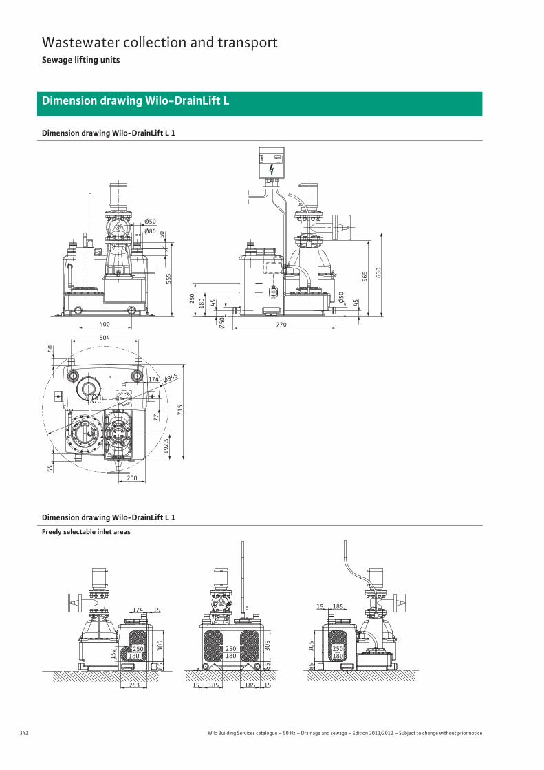
342 Wilo Building Services catalogue – 50 Hz – Drainage and sewage – Edition 2011/2012 – Subject to change without prior notice
Wastewater collection and transportSewage lifting units
Dimension drawing Wilo-DrainLift L
Dimension drawing Wilo-DrainLift L 1
Ø945174
504
400
200
Ø50
5055
5 630
565
770
454518025
0
Ø50
Ø50
Ø80
77
5055
715
192,
5
Dimension drawing Wilo-DrainLift L 1
Freely selectable inlet areas
305
85
185 1518515
250180
ZU TUSH
305
85
18515
25018015
2
253
305
85
174 15
250180
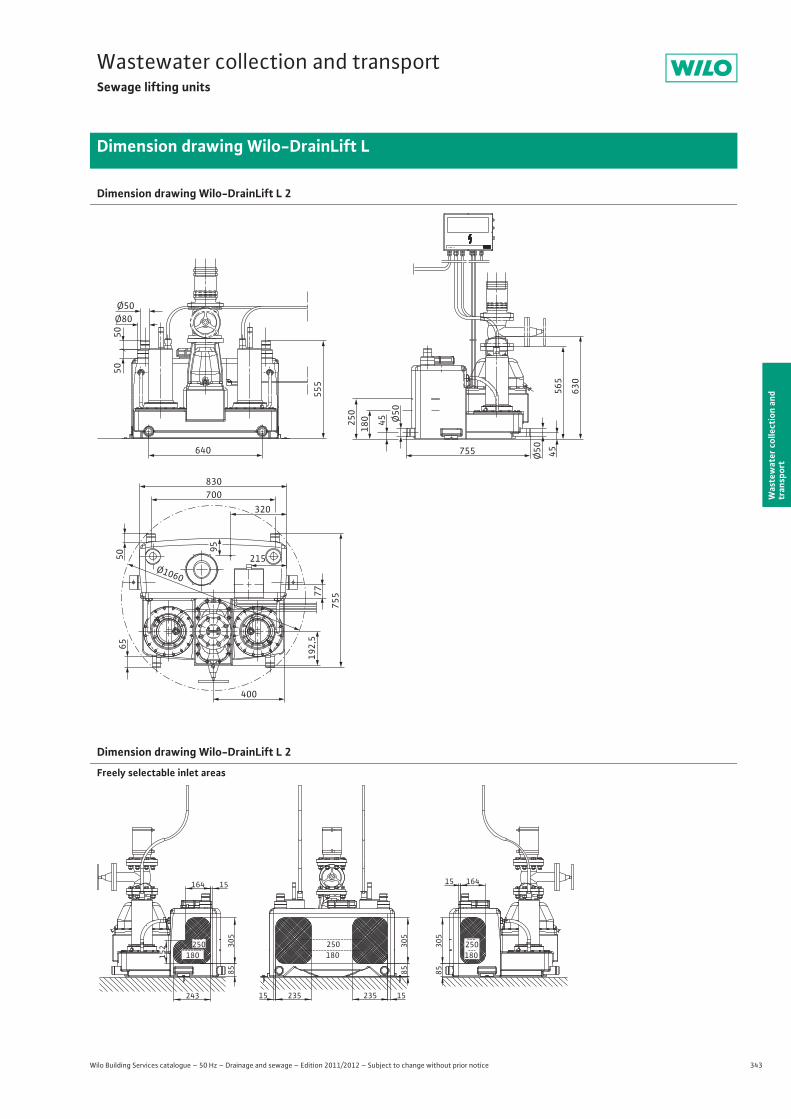
343
Wastewater collection and transportSewage lifting units
Wilo Building Services catalogue – 50 Hz – Drainage and sewage – Edition 2011/2012 – Subject to change without prior notice
Dimension drawing Wilo-DrainLift L
Was
tew
ater
col
lect
ion
and
tran
spor
t
Dimension drawing Wilo-DrainLift L 2
50
Ø80Ø50
Ø50
50
640
555
565
250
180 45
50
95
65
75577
192,
5
45Ø50755
830700
320
400
215
630
Ø1060
Dimension drawing Wilo-DrainLift L 2
Freely selectable inlet areas
250180
235 235
85305
1515
15164
305
85
243
152
180250 30
585
15 164
250180
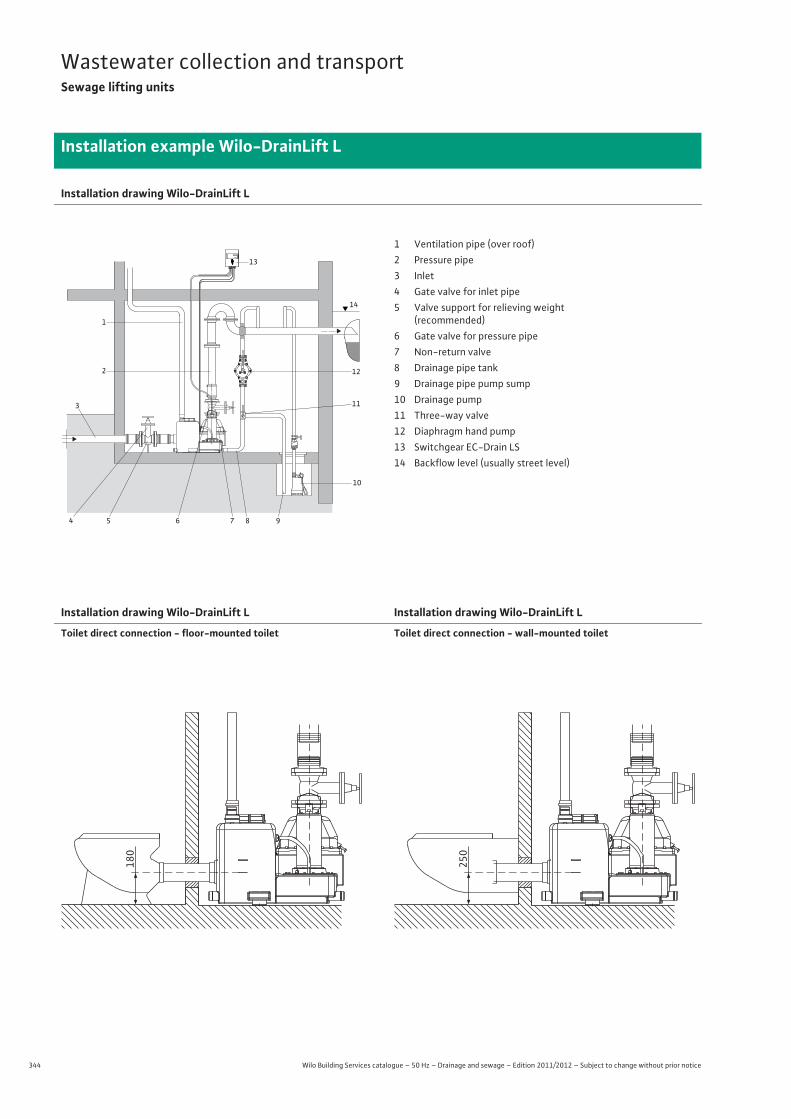
344 Wilo Building Services catalogue – 50 Hz – Drainage and sewage – Edition 2011/2012 – Subject to change without prior notice
Wastewater collection and transportSewage lifting units
Installation example Wilo-DrainLift L
Installation drawing Wilo-DrainLift L
Installation drawing Wilo-DrainLift L
Toilet direct connection - floor-mounted toilet
Installation drawing Wilo-DrainLift L
Toilet direct connection - wall-mounted toilet
13
12
10
98765
3
4
2
1
11
14
1 Ventilation pipe (over roof)2 Pressure pipe3 Inlet4 Gate valve for inlet pipe5 Valve support for relieving weight
(recommended)6 Gate valve for pressure pipe7 Non-return valve8 Drainage pipe tank9 Drainage pipe pump sump10 Drainage pump11 Three-way valve12 Diaphragm hand pump13 Switchgear EC-Drain LS14 Backflow level (usually street level)
180
250
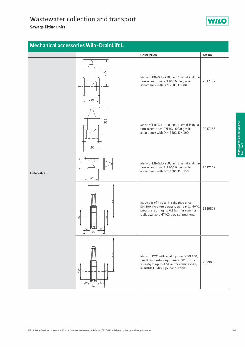
345
Wastewater collection and transportSewage lifting units
Wilo Building Services catalogue – 50 Hz – Drainage and sewage – Edition 2011/2012 – Subject to change without prior notice
Mechanical accessories Wilo-DrainLift L
Was
tew
ater
col
lect
ion
and
tran
spor
t
Description Art no.
Gate valve
Made of EN-GJL-250, incl. 1 set of installa-tion accessories, PN 10/16 flanges inaccordance with DIN 2501, DN 80
2017162
Made of EN-GJL-250, incl. 1 set of installa-tion accessories, PN 10/16 flanges inaccordance with DIN 2501, DN 100
2017163
Made of EN-GJL-250, incl. 1 set of installa-tion accessories, PN 10/16 flanges inaccordance with DIN 2501, DN 150
2017164
Made out of PVC with solid pipe ends DN 100, fluid temperature up to max. 60°C, pressure-tight up to 0.5 bar, for commer-cially available HT/KG pipe connections.
2529808
Made of PVC with solid pipe ends DN 150, fluid temperature up to max. 60°C, pres-sure-tight up to 0.5 bar, for commercially available HT/KG pipe connections.
2529809
295
180
325
190
210
285
60 60
110
110
450
176
60 60
150
150
650
227
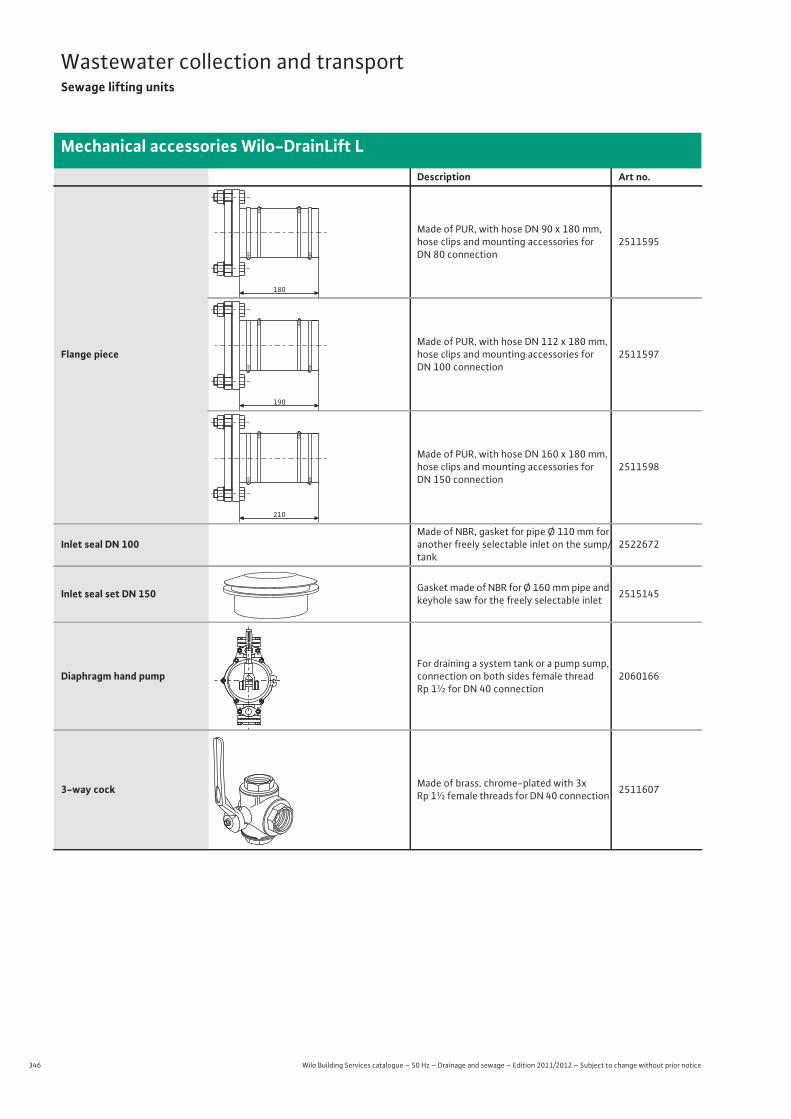
346 Wilo Building Services catalogue – 50 Hz – Drainage and sewage – Edition 2011/2012 – Subject to change without prior notice
Wastewater collection and transportSewage lifting units
Mechanical accessories Wilo-DrainLift L
Flange piece
Made of PUR, with hose DN 90 x 180 mm, hose clips and mounting accessories for DN 80 connection
2511595
Made of PUR, with hose DN 112 x 180 mm, hose clips and mounting accessories for DN 100 connection
2511597
Made of PUR, with hose DN 160 x 180 mm, hose clips and mounting accessories for DN 150 connection
2511598
Inlet seal DN 100Made of NBR, gasket for pipe Ø 110 mm for another freely selectable inlet on the sump/tank
2522672
Inlet seal set DN 150 Gasket made of NBR for Ø 160 mm pipe and keyhole saw for the freely selectable inlet 2515145
Diaphragm hand pumpFor draining a system tank or a pump sump, connection on both sides female thread Rp 1½ for DN 40 connection
2060166
3-way cock Made of brass, chrome-plated with 3x Rp 1½ female threads for DN 40 connection 2511607
Description Art no.
180
190
210
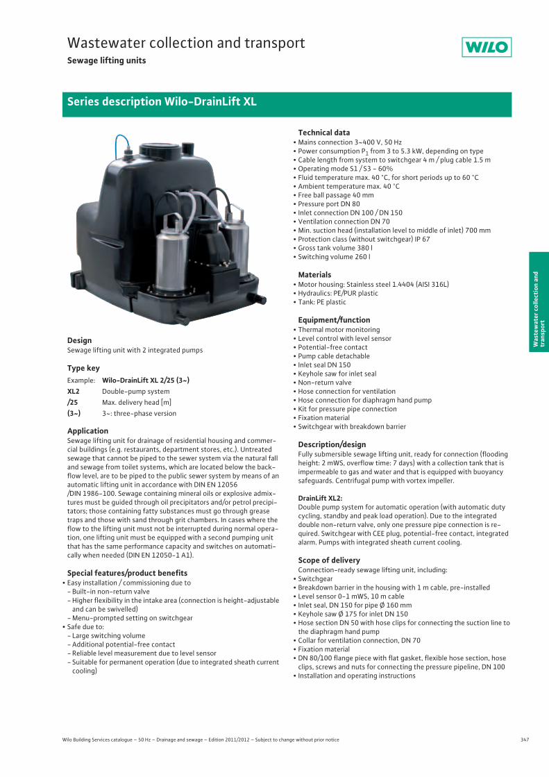
347
Wastewater collection and transportSewage lifting units
Wilo Building Services catalogue – 50 Hz – Drainage and sewage – Edition 2011/2012 – Subject to change without prior notice
Series description Wilo-DrainLift XL
Was
tew
ater
col
lect
ion
and
tran
spor
t
DesignSewage lifting unit with 2 integrated pumps
Type key
ApplicationSewage lifting unit for drainage of residential housing and commer-cial buildings (e.g. restaurants, department stores, etc.). Untreated sewage that cannot be piped to the sewer system via the natural fall and sewage from toilet systems, which are located below the back-flow level, are to be piped to the public sewer system by means of an automatic lifting unit in accordance with DIN EN 12056/DIN 1986-100. Sewage containing mineral oils or explosive admix-tures must be guided through oil precipitators and/or petrol precipi-tators; those containing fatty substances must go through grease traps and those with sand through grit chambers. In cases where the flow to the lifting unit must not be interrupted during normal opera-tion, one lifting unit must be equipped with a second pumping unit that has the same performance capacity and switches on automati-cally when needed (DIN EN 12050-1 A1).
Special features/product benefits• Easy installation / commissioning due to
- Built-in non-return valve- Higher flexibility in the intake area (connection is height-adjustable and can be swivelled)
- Menu-prompted setting on switchgear• Safe due to:
- Large switching volume- Additional potential-free contact- Reliable level measurement due to level sensor- Suitable for permanent operation (due to integrated sheath current
cooling)
Technical data• Mains connection 3~400 V, 50 Hz• Power consumption P1 from 3 to 5.3 kW, depending on type• Cable length from system to switchgear 4 m / plug cable 1.5 m• Operating mode S1 / S3 - 60%• Fluid temperature max. 40 °C, for short periods up to 60 °C• Ambient temperature max. 40 °C• Free ball passage 40 mm• Pressure port DN 80• Inlet connection DN 100 / DN 150• Ventilation connection DN 70• Min. suction head (installation level to middle of inlet) 700 mm• Protection class (without switchgear) IP 67• Gross tank volume 380 l• Switching volume 260 l
Materials• Motor housing: Stainless steel 1.4404 (AISI 316L)• Hydraulics: PE/PUR plastic• Tank: PE plastic
Equipment/function• Thermal motor monitoring• Level control with level sensor• Potential-free contact• Pump cable detachable• Inlet seal DN 150• Keyhole saw for inlet seal• Non-return valve• Hose connection for ventilation• Hose connection for diaphragm hand pump• Kit for pressure pipe connection• Fixation material• Switchgear with breakdown barrier
Description/designFully submersible sewage lifting unit, ready for connection (flooding height: 2 mWS, overflow time: 7 days) with a collection tank that is impermeable to gas and water and that is equipped with buoyancy safeguards. Centrifugal pump with vortex impeller.
DrainLift XL2:Double pump system for automatic operation (with automatic duty cycling, standby and peak load operation). Due to the integrated double non-return valve, only one pressure pipe connection is re-quired. Switchgear with CEE plug, potential-free contact, integrated alarm. Pumps with integrated sheath current cooling.
Scope of deliveryConnection-ready sewage lifting unit, including:
• Switchgear• Breakdown barrier in the housing with 1 m cable, pre-installed• Level sensor 0-1 mWS, 10 m cable• Inlet seal, DN 150 for pipe Ø 160 mm• Keyhole saw Ø 175 for inlet DN 150• Hose section DN 50 with hose clips for connecting the suction line to
the diaphragm hand pump• Collar for ventilation connection, DN 70• Fixation material • DN 80/100 flange piece with flat gasket, flexible hose section, hose
clips, screws and nuts for connecting the pressure pipeline, DN 100• Installation and operating instructions
Example: Wilo-DrainLift XL 2/25 (3~)XL2 Double-pump system/25 Max. delivery head [m](3~) 3~: three-phase version
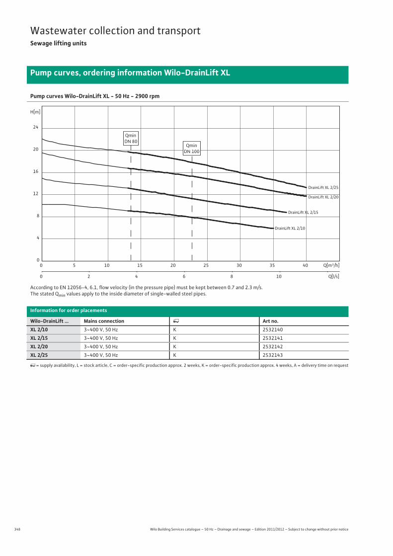
348 Wilo Building Services catalogue – 50 Hz – Drainage and sewage – Edition 2011/2012 – Subject to change without prior notice
Wastewater collection and transportSewage lifting units
Pump curves, ordering information Wilo-DrainLift XL
Pump curves Wilo-DrainLift XL - 50 Hz - 2900 rpm
According to EN 12056-4, 6.1, flow velocity (in the pressure pipe) must be kept between 0.7 and 2.3 m/s.The stated Qmin values apply to the inside diameter of single-walled steel pipes.
Information for order placements
Wilo-DrainLift ... Mains connection � Art no.XL 2/10 3~400 V, 50 Hz K 2532140
XL 2/15 3~400 V, 50 Hz K 2532141
XL 2/20 3~400 V, 50 Hz K 2532142
XL 2/25 3~400 V, 50 Hz K 2532143
�= supply availability, L = stock article, C = order-specific production approx. 2 weeks, K = order-specific production approx. 4 weeks, A = delivery time on request
DrainLift XL 2/15
DrainLift XL 2/10
DrainLift XL 2/25
DrainLift XL 2/20
Q[m³/h]0 5 10 15 20 25 30 35 40
Q[l/s]0 2 4 6 8 10
H[m]
0
4
8
12
16
20
24
QminDN 80
QminDN 100

349
Wastewater collection and transportSewage lifting units
Wilo Building Services catalogue – 50 Hz – Drainage and sewage – Edition 2011/2012 – Subject to change without prior notice
Technical data Wilo-DrainLift XL
Was
tew
ater
col
lect
ion
and
tran
spor
t
XL 2/10 XL 2/15 XL 2/20 XL 2/253~400 V, 50 Hz 3~400 V, 50 Hz 3~400 V, 50 Hz 3~400 V, 50 Hz
Motor
Power consumption P1 / kW 2x 3.0 2x 3.8 2x 4.9 2x 5.3
Nominal current IN / A 2x 6.0 2x 6.9 2x 8.5 2x 8.9
Nominal speed n / rpm 2900 2900 2900 2900
Activation type Direct Direct Direct Direct
Insulation class H H H H
Protection class IP 67 IP 67 IP 67 IP 67
Max. switching frequency per pump 1/h 30 30 30 30
Cable
Cable length from system to switchgear/plug m 4/1.5 4/1.5 4/1.5 4/1.5
Mains plug CEE CEE CEE CEE
Type of connecting cable Detachable Detachable Detachable Detachable
Permitted field of application
Max. intake/h with S3 operation V / l max. 15600 max. 15600 max. 15600 max. 15600
Operating mode per pump S1, S3-60%,120 sec
S1, S3-60%,120 sec
S1, S3-60%,120 sec
S1, S3-60%,120 sec
Max. permissible pressure in the pressure pipe p / bar 3 3 3 3
Fluid temperature T / °C +3 ... +40 +3 ... +40 +3 ... +40 +3 ... +40
Max. fluid temperature, for short periods up to 3 min T / °C 60 60 60 60
Max. ambient temperature T / °C 40 40 40 40
Connections
Pressure connection DN 80 DN 80 DN 80 DN 80
Inlet connection DN 150/DN 100 DN 150/DN 100 DN 150/DN 100 DN 150/DN 100
Bleeding DN 70 DN 70 DN 70 DN 70
Dimensions/weights
Gross volume V / l 380 380 380 380
Max. switching volume V / l 260 260 260 260
Min. water level OFF mm 80 80 80 80
Min. water level ON mm 550 550 550 550
Dimensions Width x height x depth / mm 835 x 1120 x 955 835 x 1120 x 955 835 x 1120 x 955 835 x 1120 x 955
Diagonal dimension mm 1300 1300 1300 1300
Weight approx. m / kg 108 108 108 108
Materials
Motor housing 1.4404 1.4404 1.4404 1.4404
Pump shaft 1.4404 1.4404 1.4404 1.4404
Mechanical seal SiC/SiC SiC/SiC SiC/SiC SiC/SiC
Pump housing PE/PUR PE/PUR PE/PUR PE/PUR
Impeller PUR PUR PUR PUR
Tank material PE PE PE PE
P1 refers to the maximum power consumption. All of the data applies to 3~400 V, 50 Hz and a density of 1 kg/dm3.
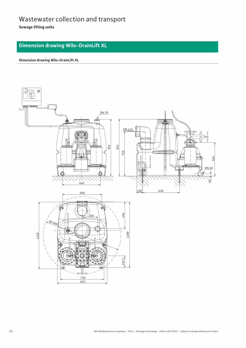
350 Wilo Building Services catalogue – 50 Hz – Drainage and sewage – Edition 2011/2012 – Subject to change without prior notice
Wastewater collection and transportSewage lifting units
Dimension drawing Wilo-DrainLift XL
Dimension drawing Wilo-DrainLift XL
835730
1120
450
260
660
640
620
DN 40
4056
5
100
DN 70
DN 150
955
955
750
1100
Ø1300
197,
5
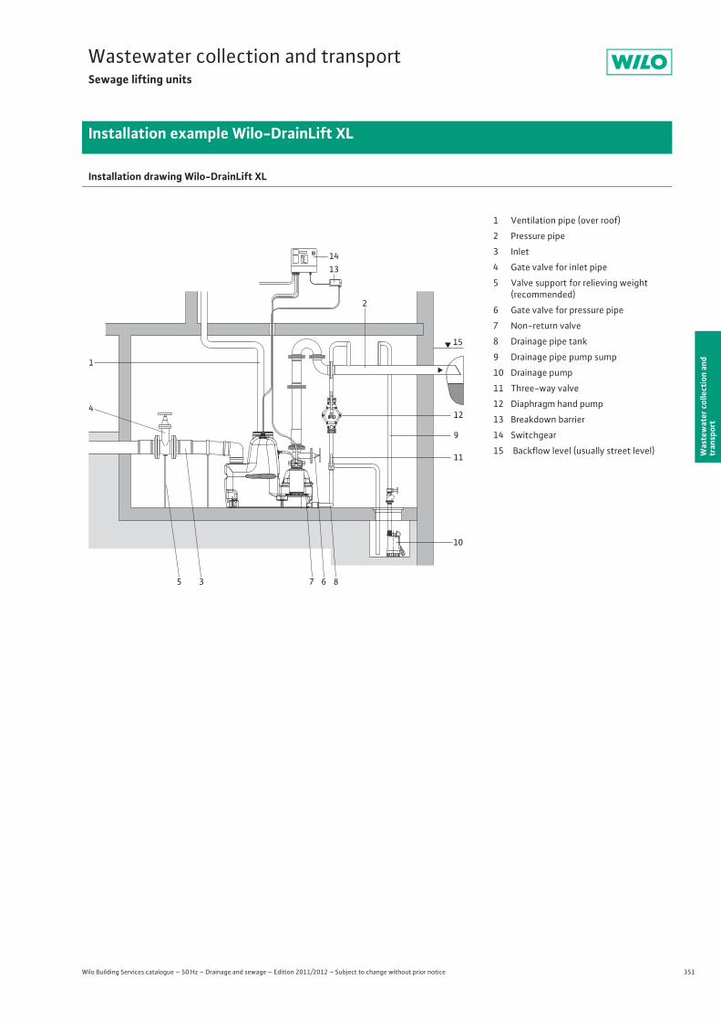
351
Wastewater collection and transportSewage lifting units
Wilo Building Services catalogue – 50 Hz – Drainage and sewage – Edition 2011/2012 – Subject to change without prior notice
Installation example Wilo-DrainLift XL
Was
tew
ater
col
lect
ion
and
tran
spor
t
Installation drawing Wilo-DrainLift XL
12
9
11
6 8735
10
2
1
4
1413
15
1 Ventilation pipe (over roof)
2 Pressure pipe
3 Inlet
4 Gate valve for inlet pipe
5 Valve support for relieving weight(recommended)
6 Gate valve for pressure pipe
7 Non-return valve
8 Drainage pipe tank
9 Drainage pipe pump sump
10 Drainage pump
11 Three-way valve
12 Diaphragm hand pump
13 Breakdown barrier
14 Switchgear
15 Backflow level (usually street level)
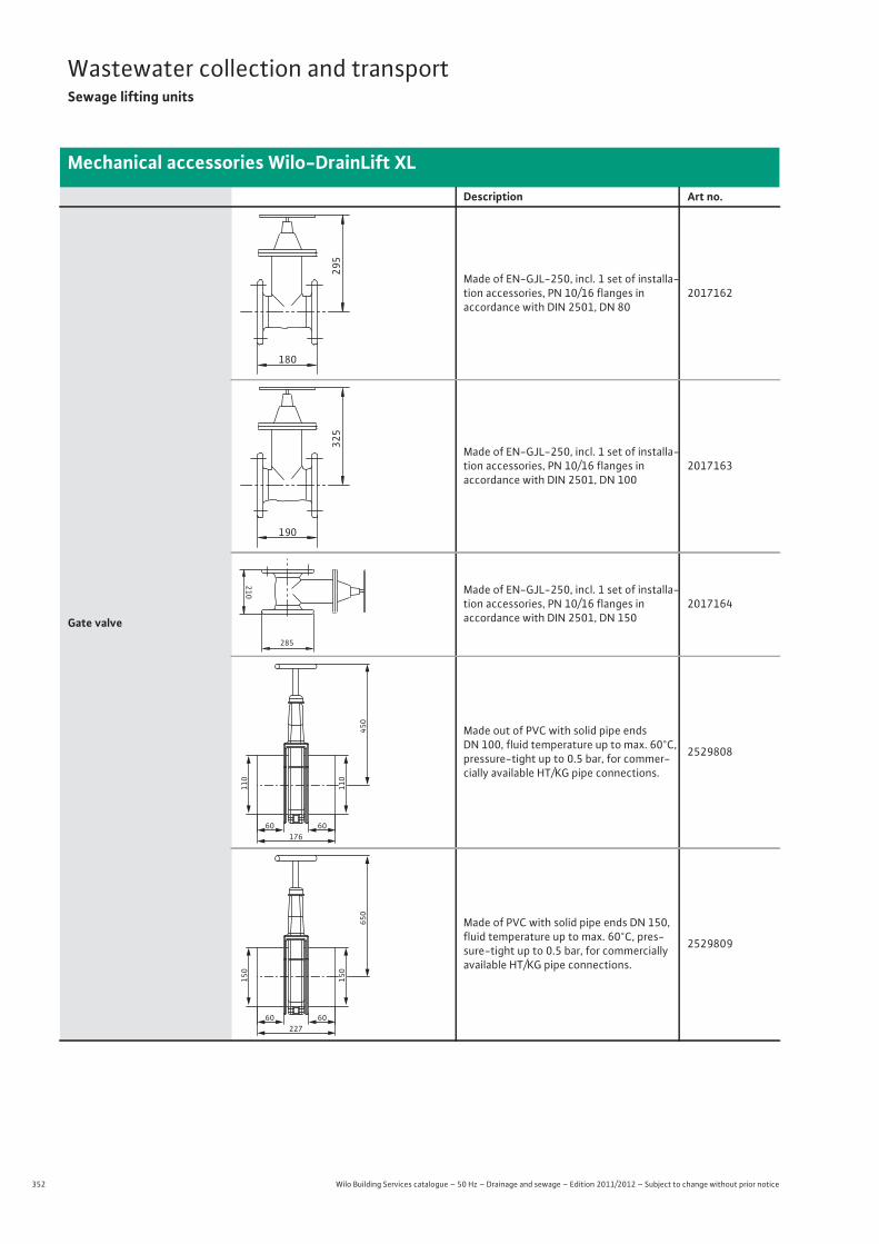
352 Wilo Building Services catalogue – 50 Hz – Drainage and sewage – Edition 2011/2012 – Subject to change without prior notice
Wastewater collection and transportSewage lifting units
Mechanical accessories Wilo-DrainLift XL
Description Art no.
Gate valve
Made of EN-GJL-250, incl. 1 set of installa-tion accessories, PN 10/16 flanges inaccordance with DIN 2501, DN 80
2017162
Made of EN-GJL-250, incl. 1 set of installa-tion accessories, PN 10/16 flanges inaccordance with DIN 2501, DN 100
2017163
Made of EN-GJL-250, incl. 1 set of installa-tion accessories, PN 10/16 flanges inaccordance with DIN 2501, DN 150
2017164
Made out of PVC with solid pipe ends DN 100, fluid temperature up to max. 60°C, pressure-tight up to 0.5 bar, for commer-cially available HT/KG pipe connections.
2529808
Made of PVC with solid pipe ends DN 150, fluid temperature up to max. 60°C, pres-sure-tight up to 0.5 bar, for commercially available HT/KG pipe connections.
2529809
295
180
325
190
210285
60 60
110
110
450
176
60 60
150
150
650
227
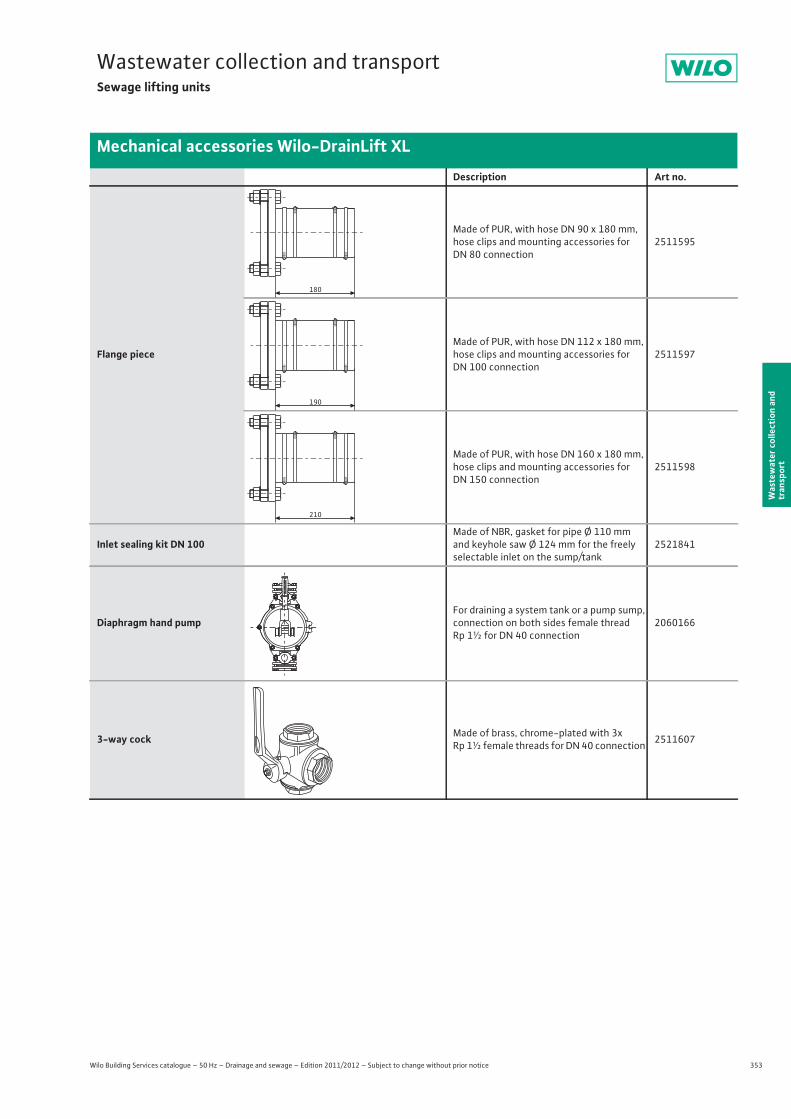
353
Wastewater collection and transportSewage lifting units
Wilo Building Services catalogue – 50 Hz – Drainage and sewage – Edition 2011/2012 – Subject to change without prior notice
Mechanical accessories Wilo-DrainLift XL
Was
tew
ater
col
lect
ion
and
tran
spor
t
Flange piece
Made of PUR, with hose DN 90 x 180 mm, hose clips and mounting accessories for DN 80 connection
2511595
Made of PUR, with hose DN 112 x 180 mm, hose clips and mounting accessories for DN 100 connection
2511597
Made of PUR, with hose DN 160 x 180 mm, hose clips and mounting accessories for DN 150 connection
2511598
Inlet sealing kit DN 100Made of NBR, gasket for pipe Ø 110 mm and keyhole saw Ø 124 mm for the freely selectable inlet on the sump/tank
2521841
Diaphragm hand pumpFor draining a system tank or a pump sump, connection on both sides female thread Rp 1½ for DN 40 connection
2060166
3-way cock Made of brass, chrome-plated with 3x Rp 1½ female threads for DN 40 connection 2511607
Description Art no.
180
190
210
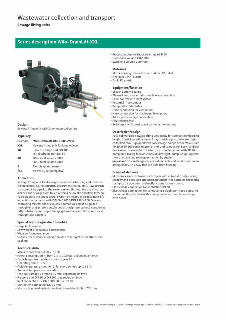
354 Wilo Building Services catalogue – 50 Hz – Drainage and sewage – Edition 2011/2012 – Subject to change without prior notice
Wastewater collection and transportSewage lifting units
Series description Wilo-DrainLift XXL
DesignSewage lifting unit with 2 dry-mounted pumps
Type key
ApplicationSewage lifting unit for drainage of residential housing and commer-cial buildings (e.g. restaurants, department stores, etc.). Raw sewage that cannot be piped to the sewer system through the use of natural inclines and sewage from toilet systems below the backflow level are to be piped to the public sewer system by means of an automatic lift-ing unit in accordance with DIN EN 12056/DIN 1986-100. Sewage containing mineral oils or explosive admixtures must be guided through oil precipitators and/or petrol precipitators; those containing fatty substances must go through grease traps and those with sand through sand catchers.
Special features/product benefits• Large tank volume• Low weight of individual components• Wide performance range• Suitable for permanent operation (due to integrated sheath current
cooling)
Technical data• Mains connection 3~400 V, 50 Hz• Power consumption P1 from 2.3 to 10.0 kW, depending on type• Cable length from system to switchgear 10 m• Operating mode S1, S3• Fluid temperature max. 40 °C, for short periods up to 65 °C• Ambient temperature max. 40 °C• Free ball passage 78 mm to 95 mm, depending on type• Pressure port DN 80 or DN 100, depending on type• Inlet connection 3 x DN 100/150, 1 x DN 100• Ventilation connection DN 70 mm• Min. suction head (installation level to middle of inlet) 700 mm
• Protection class (without switchgear) IP 68• Gross tank volume 400/800 l• Switching volume 200/400 l
Materials• Motor housing: stainless steel 1.4404 (AISI 316L)• Hydraulics: PUR plastic• Tank: PE plastic
Equipment/function• Sheath current cooling• Thermal motor monitoring and leakage detection• Level control with level sensor• Potential-free contact• Pump cable detachable• Hose connection for ventilation• Hose connection for diaphragm hand pump• Kit for pressure pipe connection• Fixation material• Switchgear with breakdown barrier in the housing
Description/designFully submersible sewage lifting unit, ready for connection (flooding height: 2 mWS, overflow time: 7 days), with a gas- and watertight collection tank. Equipped with two sewage pumps of the Wilo-Drain TP 80 or TP 100 series (material: Inox and composite). Easy handling due to low total weight of system, e.g. double system with TP 80 pump only 160 kg (heaviest individual weight: pump 62 kg). Optimal tank drainage due to deep extraction by suction.Important: The switchgear is not submersible and must therefore be arranged in such a way that it is safe from flooding.
Scope of delivery• Microprocessor-controlled switchgear with automatic duty cycling,
standby and peak load operation, potential-free contacts and indica-tor lights for operation and malfunctions for each pump.
• Elastic hose connection for ventilation DN 70.• Elastic hose connection for connecting a diaphragm hand pump. Kit
for connecting the tank with a pump (including ventilation flange with hose).
Example: Wilo-DrainLift XXL 1080-2/8.4XXL Sewage lifting unit for large objects10 10 = discharge port DN 100
8 = discharge port DN 8080 80 = total volume 800 l
40 = total volume 400 l2 Double-pump system/8.4 Power P2 per pump [kW]
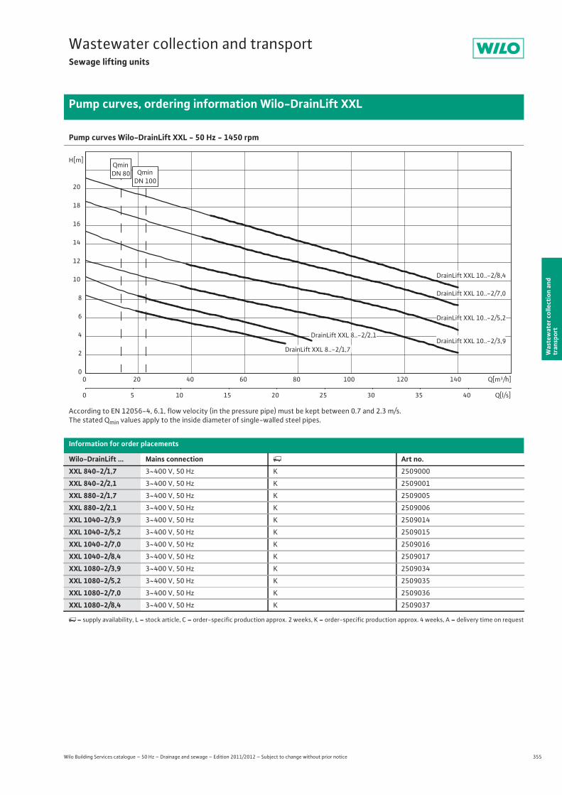
355
Wastewater collection and transportSewage lifting units
Wilo Building Services catalogue – 50 Hz – Drainage and sewage – Edition 2011/2012 – Subject to change without prior notice
Pump curves, ordering information Wilo-DrainLift XXL
Was
tew
ater
col
lect
ion
and
tran
spor
t
Pump curves Wilo-DrainLift XXL - 50 Hz - 1450 rpm
According to EN 12056-4, 6.1, flow velocity (in the pressure pipe) must be kept between 0.7 and 2.3 m/s.The stated Qmin values apply to the inside diameter of single-walled steel pipes.
Information for order placements
Wilo-DrainLift ... Mains connection � Art no.XXL 840-2/1,7 3~400 V, 50 Hz K 2509000
XXL 840-2/2,1 3~400 V, 50 Hz K 2509001
XXL 880-2/1,7 3~400 V, 50 Hz K 2509005
XXL 880-2/2,1 3~400 V, 50 Hz K 2509006
XXL 1040-2/3,9 3~400 V, 50 Hz K 2509014
XXL 1040-2/5,2 3~400 V, 50 Hz K 2509015
XXL 1040-2/7,0 3~400 V, 50 Hz K 2509016
XXL 1040-2/8,4 3~400 V, 50 Hz K 2509017
XXL 1080-2/3,9 3~400 V, 50 Hz K 2509034
XXL 1080-2/5,2 3~400 V, 50 Hz K 2509035
XXL 1080-2/7,0 3~400 V, 50 Hz K 2509036
XXL 1080-2/8,4 3~400 V, 50 Hz K 2509037
�= supply availability, L = stock article, C = order-specific production approx. 2 weeks, K = order-specific production approx. 4 weeks, A = delivery time on request
Q[m³/h]0 20 40 60 80 100 120 140
Q[l/s]0 5 10 15 20 25 30 35 40
H[m]
0
2
4
6
8
10
12
14
16
18
20
QminDN 80 Qmin
DN 100
DrainLift XXL 8..-2/2,1
DrainLift XXL 10..-2/8,4
DrainLift XXL 8..-2/1,7
DrainLift XXL 10..-2/5,2
DrainLift XXL 10..-2/3,9
DrainLift XXL 10..-2/7,0
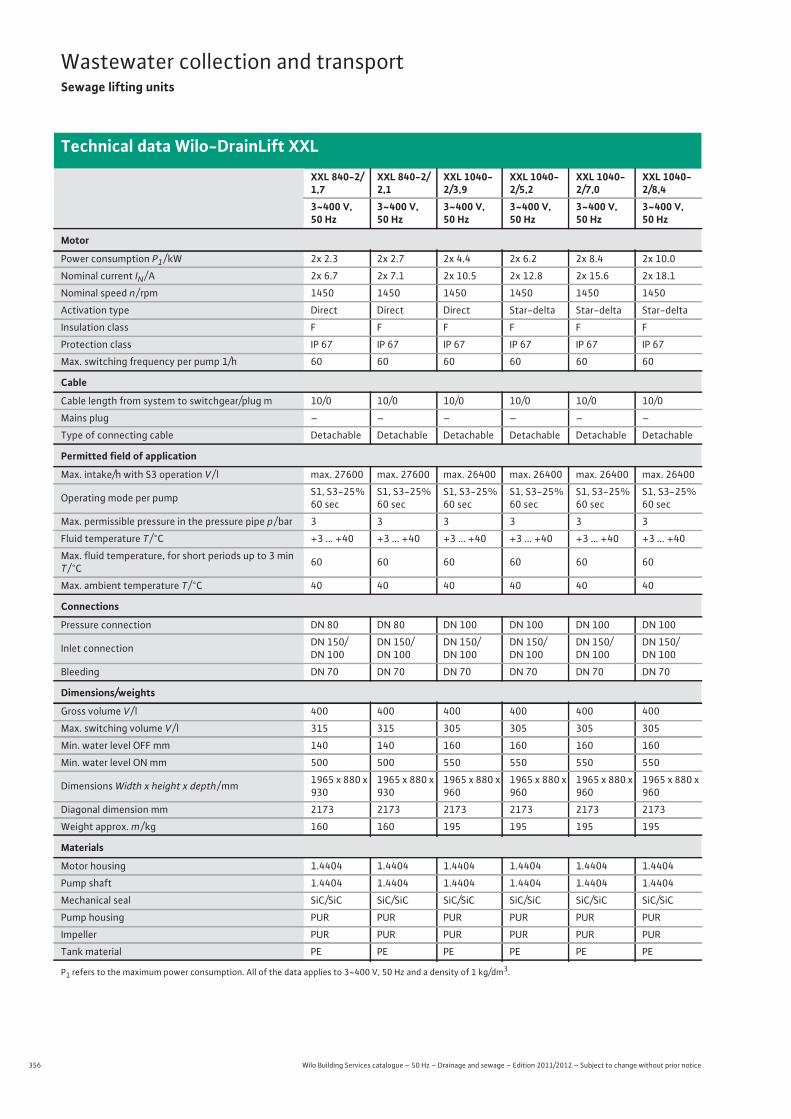
356 Wilo Building Services catalogue – 50 Hz – Drainage and sewage – Edition 2011/2012 – Subject to change without prior notice
Wastewater collection and transportSewage lifting units
Technical data Wilo-DrainLift XXL
XXL 840-2/1,7
XXL 840-2/2,1
XXL 1040-2/3,9
XXL 1040-2/5,2
XXL 1040-2/7,0
XXL 1040-2/8,4
3~400 V, 50 Hz
3~400 V, 50 Hz
3~400 V, 50 Hz
3~400 V, 50 Hz
3~400 V, 50 Hz
3~400 V, 50 Hz
Motor
Power consumption P1 / kW 2x 2.3 2x 2.7 2x 4.4 2x 6.2 2x 8.4 2x 10.0
Nominal current IN / A 2x 6.7 2x 7.1 2x 10.5 2x 12.8 2x 15.6 2x 18.1
Nominal speed n / rpm 1450 1450 1450 1450 1450 1450
Activation type Direct Direct Direct Star-delta Star-delta Star-delta
Insulation class F F F F F F
Protection class IP 67 IP 67 IP 67 IP 67 IP 67 IP 67
Max. switching frequency per pump 1/h 60 60 60 60 60 60
Cable
Cable length from system to switchgear/plug m 10/0 10/0 10/0 10/0 10/0 10/0
Mains plug – – – – – –
Type of connecting cable Detachable Detachable Detachable Detachable Detachable Detachable
Permitted field of application
Max. intake/h with S3 operation V / l max. 27600 max. 27600 max. 26400 max. 26400 max. 26400 max. 26400
Operating mode per pump S1, S3-25% 60 sec
S1, S3-25% 60 sec
S1, S3-25% 60 sec
S1, S3-25% 60 sec
S1, S3-25% 60 sec
S1, S3-25% 60 sec
Max. permissible pressure in the pressure pipe p / bar 3 3 3 3 3 3
Fluid temperature T / °C +3 ... +40 +3 ... +40 +3 ... +40 +3 ... +40 +3 ... +40 +3 ... +40
Max. fluid temperature, for short periods up to 3 min T / °C 60 60 60 60 60 60
Max. ambient temperature T / °C 40 40 40 40 40 40
Connections
Pressure connection DN 80 DN 80 DN 100 DN 100 DN 100 DN 100
Inlet connection DN 150/DN 100
DN 150/DN 100
DN 150/DN 100
DN 150/DN 100
DN 150/DN 100
DN 150/DN 100
Bleeding DN 70 DN 70 DN 70 DN 70 DN 70 DN 70
Dimensions/weights
Gross volume V / l 400 400 400 400 400 400
Max. switching volume V / l 315 315 305 305 305 305
Min. water level OFF mm 140 140 160 160 160 160
Min. water level ON mm 500 500 550 550 550 550
Dimensions Width x height x depth / mm 1965 x 880 x 930
1965 x 880 x 930
1965 x 880 x 960
1965 x 880 x 960
1965 x 880 x 960
1965 x 880 x 960
Diagonal dimension mm 2173 2173 2173 2173 2173 2173
Weight approx. m / kg 160 160 195 195 195 195
Materials
Motor housing 1.4404 1.4404 1.4404 1.4404 1.4404 1.4404
Pump shaft 1.4404 1.4404 1.4404 1.4404 1.4404 1.4404
Mechanical seal SiC/SiC SiC/SiC SiC/SiC SiC/SiC SiC/SiC SiC/SiC
Pump housing PUR PUR PUR PUR PUR PUR
Impeller PUR PUR PUR PUR PUR PUR
Tank material PE PE PE PE PE PE
P1 refers to the maximum power consumption. All of the data applies to 3~400 V, 50 Hz and a density of 1 kg/dm3.
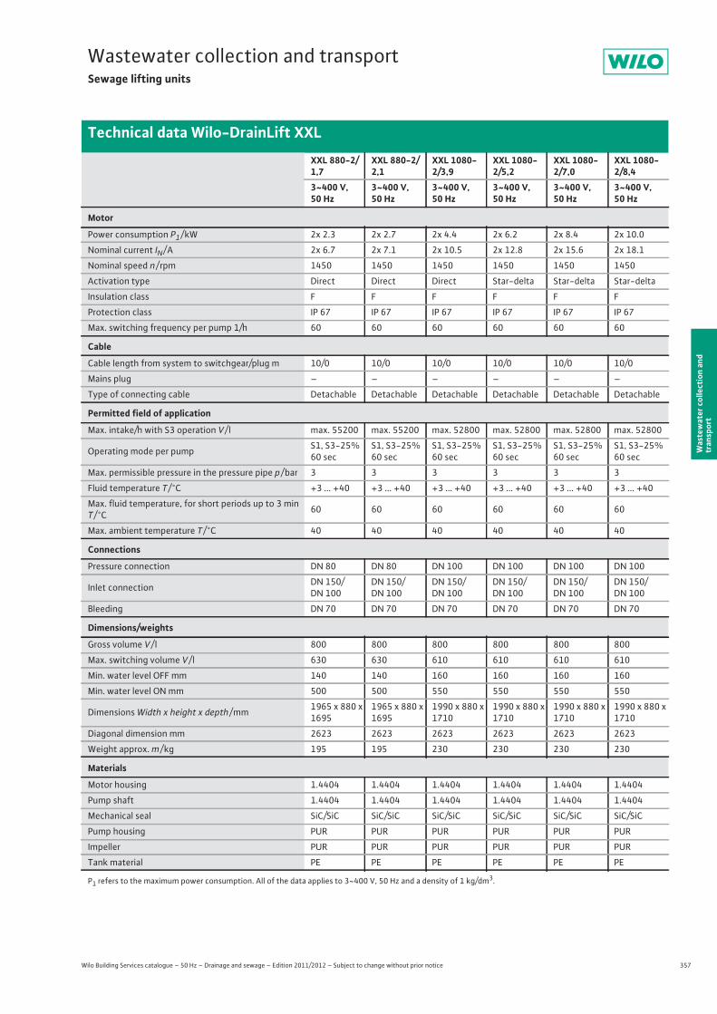
357
Wastewater collection and transportSewage lifting units
Wilo Building Services catalogue – 50 Hz – Drainage and sewage – Edition 2011/2012 – Subject to change without prior notice
Technical data Wilo-DrainLift XXL
Was
tew
ater
col
lect
ion
and
tran
spor
t
XXL 880-2/1,7
XXL 880-2/2,1
XXL 1080-2/3,9
XXL 1080-2/5,2
XXL 1080-2/7,0
XXL 1080-2/8,4
3~400 V, 50 Hz
3~400 V, 50 Hz
3~400 V, 50 Hz
3~400 V, 50 Hz
3~400 V, 50 Hz
3~400 V, 50 Hz
Motor
Power consumption P1 / kW 2x 2.3 2x 2.7 2x 4.4 2x 6.2 2x 8.4 2x 10.0
Nominal current IN / A 2x 6.7 2x 7.1 2x 10.5 2x 12.8 2x 15.6 2x 18.1
Nominal speed n / rpm 1450 1450 1450 1450 1450 1450
Activation type Direct Direct Direct Star-delta Star-delta Star-delta
Insulation class F F F F F F
Protection class IP 67 IP 67 IP 67 IP 67 IP 67 IP 67
Max. switching frequency per pump 1/h 60 60 60 60 60 60
Cable
Cable length from system to switchgear/plug m 10/0 10/0 10/0 10/0 10/0 10/0
Mains plug – – – – – –
Type of connecting cable Detachable Detachable Detachable Detachable Detachable Detachable
Permitted field of application
Max. intake/h with S3 operation V / l max. 55200 max. 55200 max. 52800 max. 52800 max. 52800 max. 52800
Operating mode per pump S1, S3-25% 60 sec
S1, S3-25% 60 sec
S1, S3-25% 60 sec
S1, S3-25% 60 sec
S1, S3-25% 60 sec
S1, S3-25% 60 sec
Max. permissible pressure in the pressure pipe p / bar 3 3 3 3 3 3
Fluid temperature T / °C +3 ... +40 +3 ... +40 +3 ... +40 +3 ... +40 +3 ... +40 +3 ... +40
Max. fluid temperature, for short periods up to 3 min T / °C 60 60 60 60 60 60
Max. ambient temperature T / °C 40 40 40 40 40 40
Connections
Pressure connection DN 80 DN 80 DN 100 DN 100 DN 100 DN 100
Inlet connection DN 150/DN 100
DN 150/DN 100
DN 150/DN 100
DN 150/DN 100
DN 150/DN 100
DN 150/DN 100
Bleeding DN 70 DN 70 DN 70 DN 70 DN 70 DN 70
Dimensions/weights
Gross volume V / l 800 800 800 800 800 800
Max. switching volume V / l 630 630 610 610 610 610
Min. water level OFF mm 140 140 160 160 160 160
Min. water level ON mm 500 500 550 550 550 550
Dimensions Width x height x depth / mm 1965 x 880 x 1695
1965 x 880 x 1695
1990 x 880 x 1710
1990 x 880 x 1710
1990 x 880 x 1710
1990 x 880 x 1710
Diagonal dimension mm 2623 2623 2623 2623 2623 2623
Weight approx. m / kg 195 195 230 230 230 230
Materials
Motor housing 1.4404 1.4404 1.4404 1.4404 1.4404 1.4404
Pump shaft 1.4404 1.4404 1.4404 1.4404 1.4404 1.4404
Mechanical seal SiC/SiC SiC/SiC SiC/SiC SiC/SiC SiC/SiC SiC/SiC
Pump housing PUR PUR PUR PUR PUR PUR
Impeller PUR PUR PUR PUR PUR PUR
Tank material PE PE PE PE PE PE
P1 refers to the maximum power consumption. All of the data applies to 3~400 V, 50 Hz and a density of 1 kg/dm3.
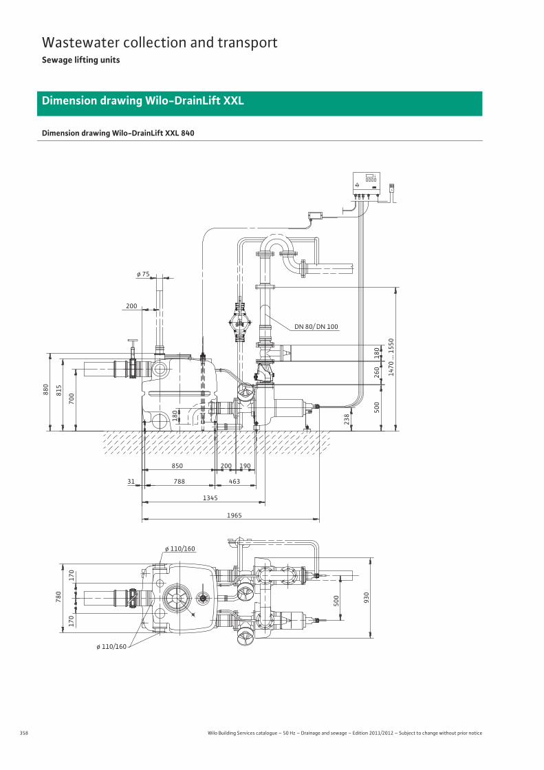
358 Wilo Building Services catalogue – 50 Hz – Drainage and sewage – Edition 2011/2012 – Subject to change without prior notice
Wastewater collection and transportSewage lifting units
Dimension drawing Wilo-DrainLift XXL
Dimension drawing Wilo-DrainLift XXL 840
ø 75
880
200
180
815
700
238
500
260
180
1470
... 1
550
DN 80/ DN 100
850 200 190
31 788 463
1345
1965
780
170
170
500
930
ø 110/160
ø 110/160
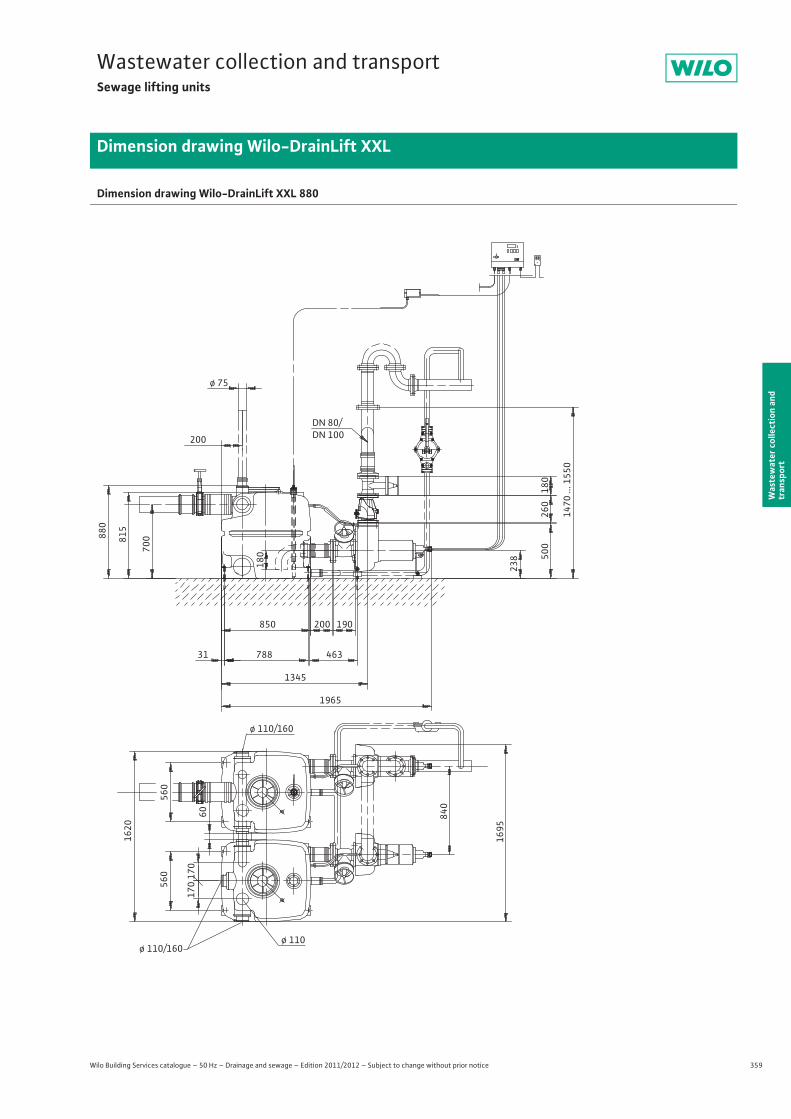
359
Wastewater collection and transportSewage lifting units
Wilo Building Services catalogue – 50 Hz – Drainage and sewage – Edition 2011/2012 – Subject to change without prior notice
Dimension drawing Wilo-DrainLift XXL
Was
tew
ater
col
lect
ion
and
tran
spor
t
Dimension drawing Wilo-DrainLift XXL 880
ø 75
880
200
815
700
DN 80/DN 100
850 200 190
31 788 463
1345
1965
180
238 50
026
018
0
1470
... 1
550
560 17
017
0
1620
60
560
840
1695
ø 110/160
ø 110/160ø 110
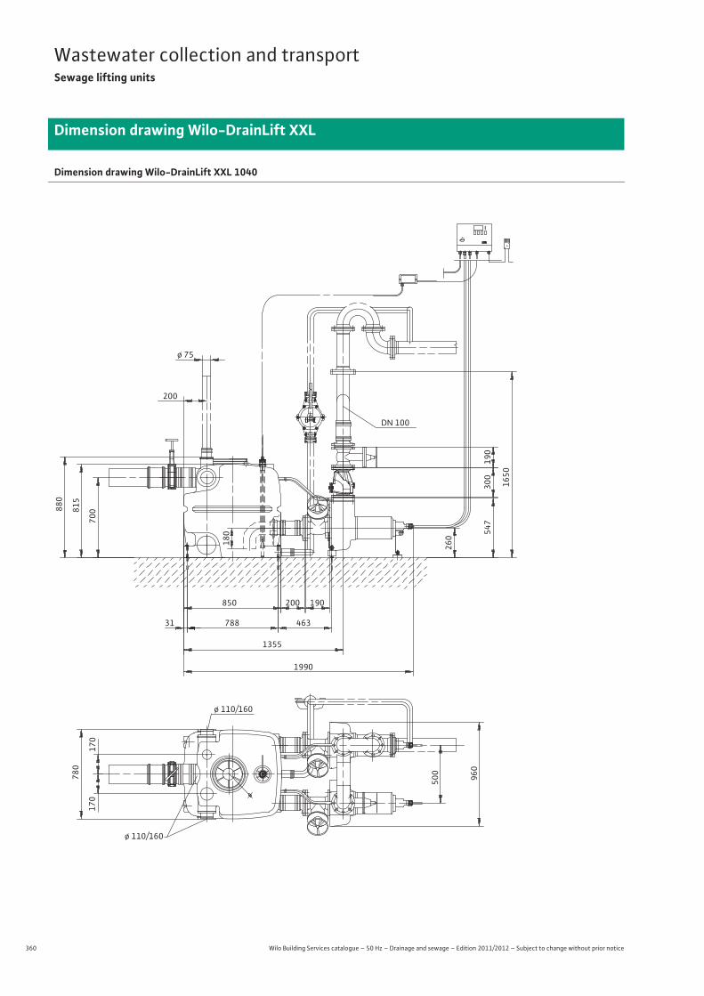
360 Wilo Building Services catalogue – 50 Hz – Drainage and sewage – Edition 2011/2012 – Subject to change without prior notice
Wastewater collection and transportSewage lifting units
Dimension drawing Wilo-DrainLift XXL
Dimension drawing Wilo-DrainLift XXL 1040
ø 75
880
200
180
815
700
260
547
300
190
1650
DN 100
850 200 190
31 788 463
1355
1990
780
170
170
500
960
ø 110/160
ø 110/160

361
Wastewater collection and transportSewage lifting units
Wilo Building Services catalogue – 50 Hz – Drainage and sewage – Edition 2011/2012 – Subject to change without prior notice
Dimension drawing Wilo-DrainLift XXL
Was
tew
ater
col
lect
ion
and
tran
spor
t
Dimension drawing Wilo-DrainLift XXL 1080
ø 75
880
200
815
700
DN 100
850 200 190
31 788 463
1355
1990
180
260 54
730
019
0
165
0
560 17
017
0
1620
60
560
840
1710
ø 110/160
ø 110/160
ø 110
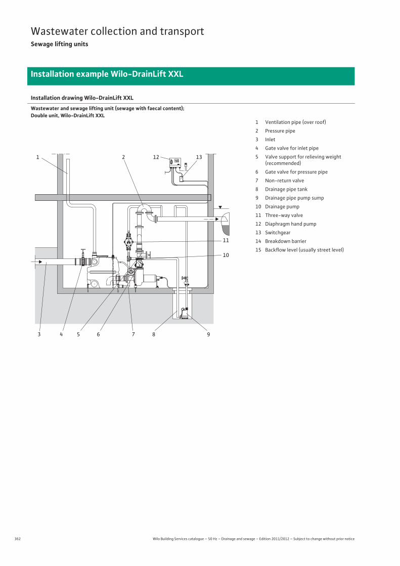
362 Wilo Building Services catalogue – 50 Hz – Drainage and sewage – Edition 2011/2012 – Subject to change without prior notice
Wastewater collection and transportSewage lifting units
Installation example Wilo-DrainLift XXL
Installation drawing Wilo-DrainLift XXL
Wastewater and sewage lifting unit (sewage with faecal content); Double unit, Wilo-DrainLift XXL
0I1 2
3 4 5 6 7 8 9
10
11
12 13
1 Ventilation pipe (over roof)
2 Pressure pipe
3 Inlet
4 Gate valve for inlet pipe
5 Valve support for relieving weight(recommended)
6 Gate valve for pressure pipe
7 Non-return valve
8 Drainage pipe tank
9 Drainage pipe pump sump
10 Drainage pump
11 Three-way valve
12 Diaphragm hand pump
13 Switchgear
14 Breakdown barrier
15 Backflow level (usually street level)
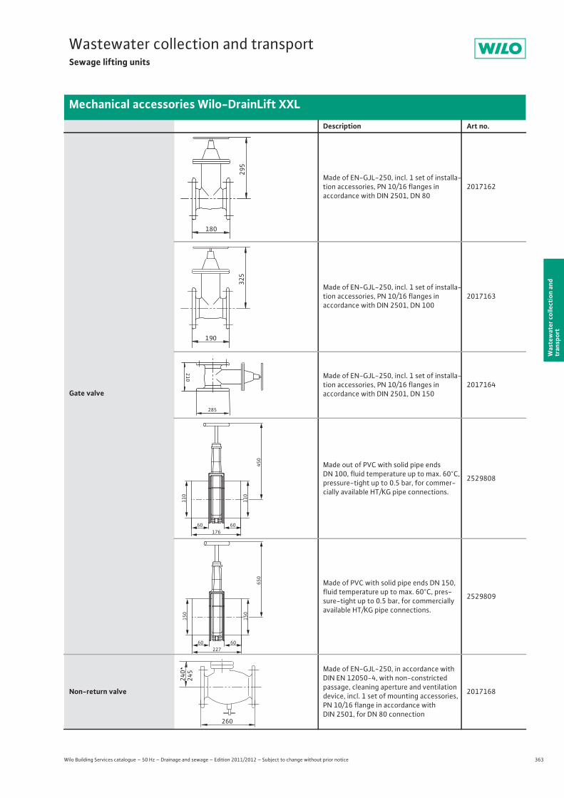
363
Wastewater collection and transportSewage lifting units
Wilo Building Services catalogue – 50 Hz – Drainage and sewage – Edition 2011/2012 – Subject to change without prior notice
Mechanical accessories Wilo-DrainLift XXL
Was
tew
ater
col
lect
ion
and
tran
spor
t
Description Art no.
Gate valve
Made of EN-GJL-250, incl. 1 set of installa-tion accessories, PN 10/16 flanges inaccordance with DIN 2501, DN 80
2017162
Made of EN-GJL-250, incl. 1 set of installa-tion accessories, PN 10/16 flanges inaccordance with DIN 2501, DN 100
2017163
Made of EN-GJL-250, incl. 1 set of installa-tion accessories, PN 10/16 flanges inaccordance with DIN 2501, DN 150
2017164
Made out of PVC with solid pipe ends DN 100, fluid temperature up to max. 60°C, pressure-tight up to 0.5 bar, for commer-cially available HT/KG pipe connections.
2529808
Made of PVC with solid pipe ends DN 150, fluid temperature up to max. 60°C, pres-sure-tight up to 0.5 bar, for commercially available HT/KG pipe connections.
2529809
Non-return valve
Made of EN-GJL-250, in accordance with DIN EN 12050-4, with non-constricted passage, cleaning aperture and ventilation device, incl. 1 set of mounting accessories, PN 10/16 flange in accordance with DIN 2501, for DN 80 connection
2017168
295
180
325
190
210
285
60 60
110
110
450
176
60 60
150
150
650
227
240*
245
260
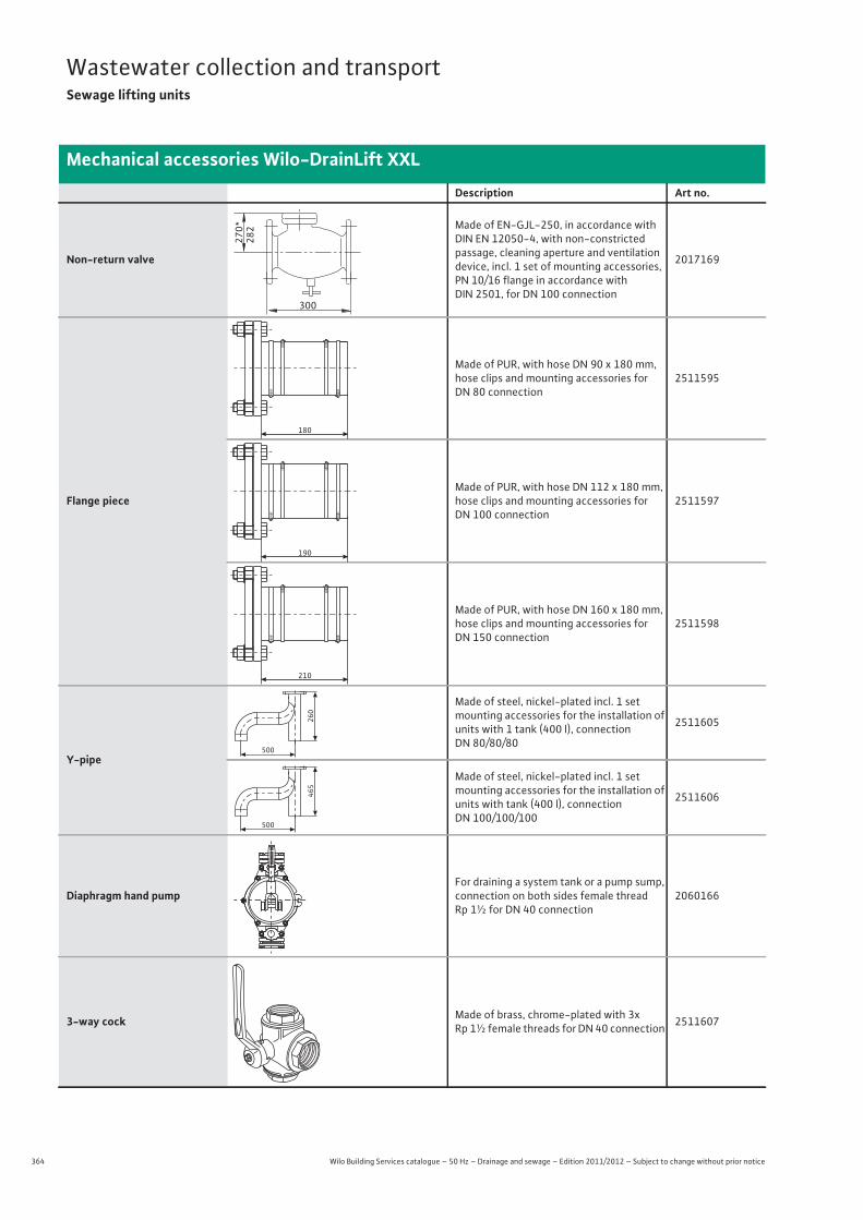
364 Wilo Building Services catalogue – 50 Hz – Drainage and sewage – Edition 2011/2012 – Subject to change without prior notice
Wastewater collection and transportSewage lifting units
Mechanical accessories Wilo-DrainLift XXL
Non-return valve
Made of EN-GJL-250, in accordance with DIN EN 12050-4, with non-constricted passage, cleaning aperture and ventilation device, incl. 1 set of mounting accessories, PN 10/16 flange in accordance with DIN 2501, for DN 100 connection
2017169
Flange piece
Made of PUR, with hose DN 90 x 180 mm, hose clips and mounting accessories for DN 80 connection
2511595
Made of PUR, with hose DN 112 x 180 mm, hose clips and mounting accessories for DN 100 connection
2511597
Made of PUR, with hose DN 160 x 180 mm, hose clips and mounting accessories for DN 150 connection
2511598
Y-pipe
Made of steel, nickel-plated incl. 1 set mounting accessories for the installation of units with 1 tank (400 l), connection DN 80/80/80
2511605
Made of steel, nickel-plated incl. 1 set mounting accessories for the installation of units with tank (400 l), connection DN 100/100/100
2511606
Diaphragm hand pumpFor draining a system tank or a pump sump, connection on both sides female thread Rp 1½ for DN 40 connection
2060166
3-way cock Made of brass, chrome-plated with 3x Rp 1½ female threads for DN 40 connection 2511607
Description Art no.
270*
282
300
180
190
210
500
260
500
465
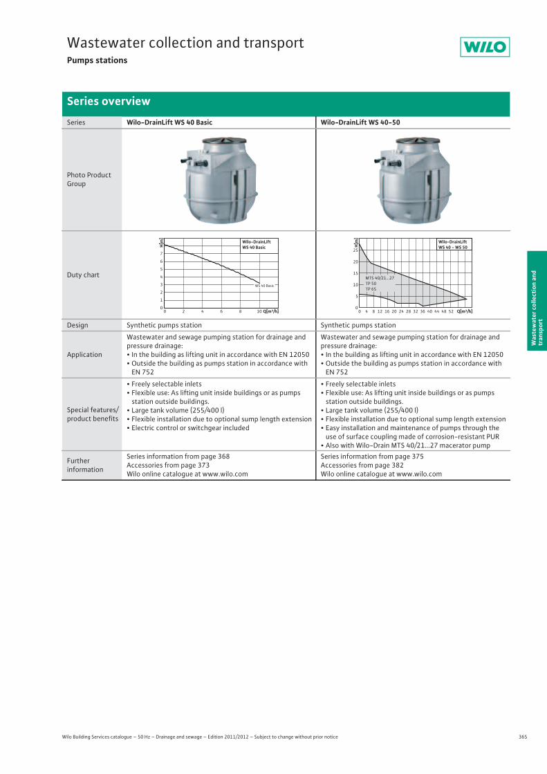
365
Wastewater collection and transportPumps stations
Wilo Building Services catalogue – 50 Hz – Drainage and sewage – Edition 2011/2012 – Subject to change without prior notice
Series overview
Was
tew
ater
col
lect
ion
and
tran
spor
t
Series Wilo-DrainLift WS 40 Basic Wilo-DrainLift WS 40-50
Photo Product Group
Duty chart
Design Synthetic pumps station Synthetic pumps station
Application
Wastewater and sewage pumping station for drainage and pressure drainage:• In the building as lifting unit in accordance with EN 12050• Outside the building as pumps station in accordance with
EN 752
Wastewater and sewage pumping station for drainage and pressure drainage:• In the building as lifting unit in accordance with EN 12050• Outside the building as pumps station in accordance with
EN 752
Special features/product benefits
• Freely selectable inlets• Flexible use: As lifting unit inside buildings or as pumps
station outside buildings.• Large tank volume (255/400 l)• Flexible installation due to optional sump length extension• Electric control or switchgear included
• Freely selectable inlets• Flexible use: As lifting unit inside buildings or as pumps
station outside buildings.• Large tank volume (255/400 l)• Flexible installation due to optional sump length extension• Easy installation and maintenance of pumps through the
use of surface coupling made of corrosion-resistant PUR• Also with Wilo-Drain MTS 40/21...27 macerator pump
Furtherinformation
Series information from page 368Accessories from page 373Wilo online catalogue at www.wilo.com
Series information from page 375Accessories from page 382Wilo online catalogue at www.wilo.com
Q[m³/h]0 2 4 6 8 10
H[m
]
0
1
2
3
4
5
6
7
Wilo-DrainLiftWS 40 Basic
WS 40 Basic
H[m]
0
25
20
15
10
5
Q[m³/h]8 12 16 20 24 28 32 36 40 44 48 5240
Wilo-DrainLiftWS 40 - WS 50
MTS 40/21...27TP 50TP 65
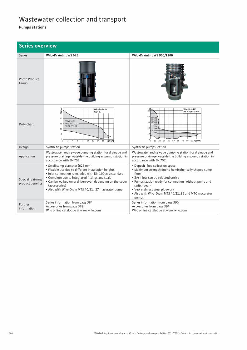
366 Wilo Building Services catalogue – 50 Hz – Drainage and sewage – Edition 2011/2012 – Subject to change without prior notice
Wastewater collection and transportPumps stations
Series overview
Series Wilo-DrainLift WS 625 Wilo-DrainLift WS 900/1100
Photo Product Group
Duty chart
Design Synthetic pumps station Synthetic pumps station
Application Wastewater and sewage pumping station for drainage and pressure drainage, outside the building as pumps station in accordance with EN 752.
Wastewater and sewage pumping station for drainage and pressure drainage, outside the building as pumps station inaccordance with EN 752.
Special features/product benefits
• Small sump diameter (625 mm)• Flexible use due to different installation heights• Inlet connection is included with DN 100 as a standard• Complete due to integrated fittings and seals• Can be walked on or driven over, depending on the cover
(accessories)• Also with Wilo-Drain MTS 40/21...27 macerator pump
• Deposit-free collection space• Maximum strength due to hemispherically shaped sump
floor• 2/4 inlets can be selected onsite• Pumps station ready for connection (without pump and
switchgear)• V4A stainless steel pipework• Also with Wilo-Drain MTS 40/21..39 and MTC macerator
pumps
Furtherinformation
Series information from page 384 Accessories from page 389Wilo online catalogue at www.wilo.com
Series information from page 390 Accessories from page 394Wilo online catalogue at www.wilo.com
H[m]
0
25
20
15
10
5
Q[m³/h]6 8 10 12 14 16420
Wilo-DrainLiftWS 625
TMW 32/11MTS 40/21...27TC 40, STS 40
Q[m³/h]50 60 70 9030 402010 8000
10
20
30
40
H[m]
Wilo-DrainLiftWS 900/WS 1100
MTC 32MTC 40MTS 40
TS 40TP 50TP 65STS 65
TP 80
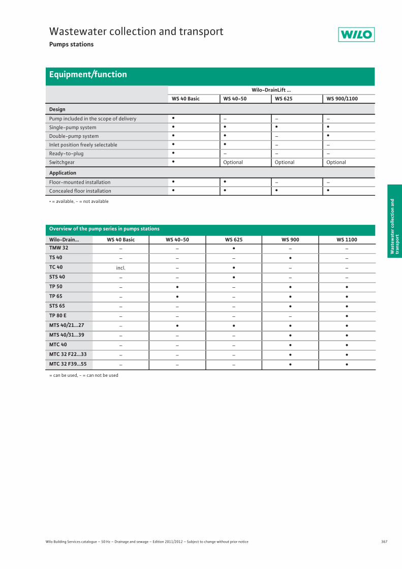
367
Wastewater collection and transportPumps stations
Wilo Building Services catalogue – 50 Hz – Drainage and sewage – Edition 2011/2012 – Subject to change without prior notice
Equipment/function
Was
tew
ater
col
lect
ion
and
tran
spor
t
= can be used, - = can not be used
Wilo-DrainLift ...WS 40 Basic WS 40-50 WS 625 WS 900/1100
Design
Pump included in the scope of delivery • – – –
Single-pump system • • • •Double-pump system • • – •Inlet position freely selectable • • – –
Ready-to-plug • – – –
Switchgear • Optional Optional Optional
Application
Floor-mounted installation • • – –
Concealed floor installation • • • •• = available, - = not available
Overview of the pump series in pumps stations
Wilo-Drain... WS 40 Basic WS 40-50 WS 625 WS 900 WS 1100TMW 32 – – • – –
TS 40 – – – • –
TC 40 incl. – • – –
STS 40 – – • – –
TP 50 – • – • •TP 65 – • – • •STS 65 – – – • •TP 80 E – – – – •MTS 40/21...27 – • • • •MTS 40/31...39 – – – • •MTC 40 – – – • •MTC 32 F22...33 – – – • •MTC 32 F39...55 – – – • •
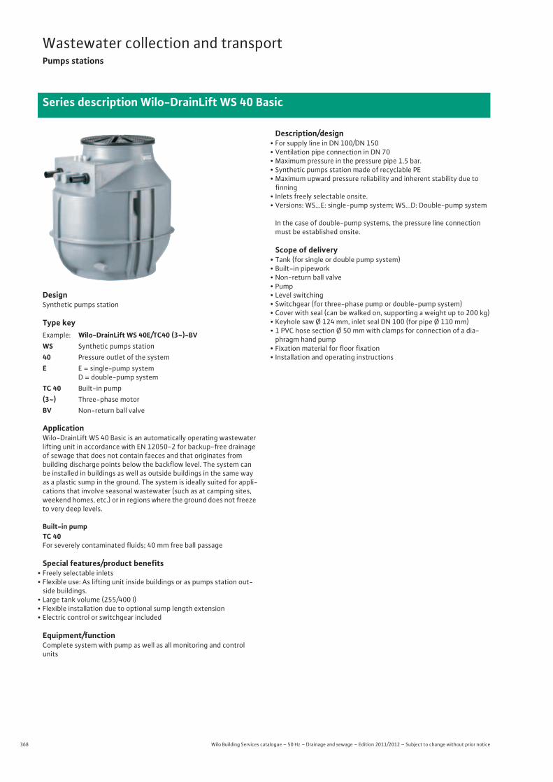
368 Wilo Building Services catalogue – 50 Hz – Drainage and sewage – Edition 2011/2012 – Subject to change without prior notice
Wastewater collection and transportPumps stations
Series description Wilo-DrainLift WS 40 Basic
DesignSynthetic pumps station
Type key
ApplicationWilo-DrainLift WS 40 Basic is an automatically operating wastewater lifting unit in accordance with EN 12050-2 for backup-free drainage of sewage that does not contain faeces and that originates from building discharge points below the backflow level. The system can be installed in buildings as well as outside buildings in the same way as a plastic sump in the ground. The system is ideally suited for appli-cations that involve seasonal wastewater (such as at camping sites, weekend homes, etc.) or in regions where the ground does not freeze to very deep levels.
Built-in pumpTC 40For severely contaminated fluids; 40 mm free ball passage
Special features/product benefits• Freely selectable inlets• Flexible use: As lifting unit inside buildings or as pumps station out-
side buildings.• Large tank volume (255/400 l)• Flexible installation due to optional sump length extension• Electric control or switchgear included
Equipment/functionComplete system with pump as well as all monitoring and control units
Description/design• For supply line in DN 100/DN 150• Ventilation pipe connection in DN 70• Maximum pressure in the pressure pipe 1,5 bar.• Synthetic pumps station made of recyclable PE• Maximum upward pressure reliability and inherent stability due to
finning• Inlets freely selectable onsite.• Versions: WS...E: single-pump system; WS...D: Double-pump system
In the case of double-pump systems, the pressure line connection must be established onsite.
Scope of delivery• Tank (for single or double pump system)• Built-in pipework• Non-return ball valve• Pump• Level switching• Switchgear (for three-phase pump or double-pump system)• Cover with seal (can be walked on, supporting a weight up to 200 kg)• Keyhole saw Ø 124 mm, inlet seal DN 100 (for pipe Ø 110 mm)• 1 PVC hose section Ø 50 mm with clamps for connection of a dia-
phragm hand pump• Fixation material for floor fixation• Installation and operating instructions
Example: Wilo-DrainLift WS 40E/TC40 (3~)-BVWS Synthetic pumps station40 Pressure outlet of the systemE E = single-pump system
D = double-pump systemTC 40 Built-in pump(3~) Three-phase motorBV Non-return ball valve
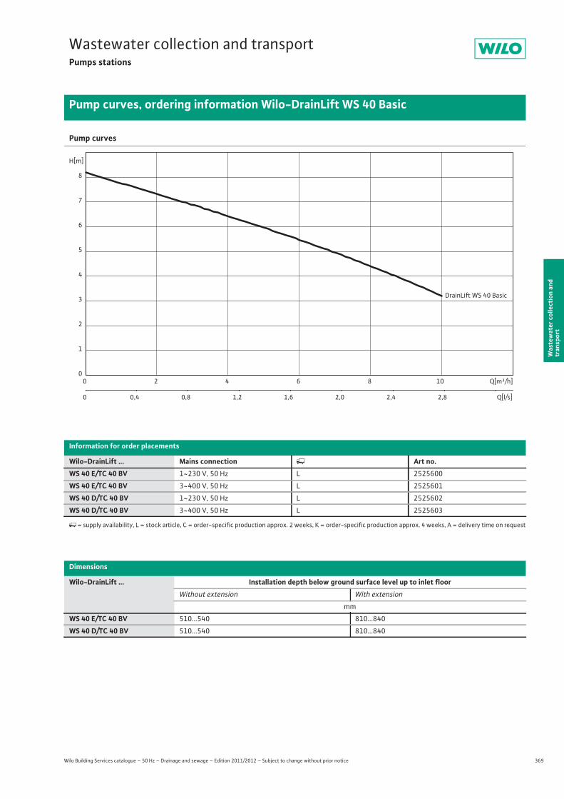
369
Wastewater collection and transportPumps stations
Wilo Building Services catalogue – 50 Hz – Drainage and sewage – Edition 2011/2012 – Subject to change without prior notice
Pump curves, ordering information Wilo-DrainLift WS 40 Basic
Was
tew
ater
col
lect
ion
and
tran
spor
t
Pump curves
Information for order placements
Wilo-DrainLift ... Mains connection � Art no.WS 40 E/TC 40 BV 1~230 V, 50 Hz L 2525600
WS 40 E/TC 40 BV 3~400 V, 50 Hz L 2525601
WS 40 D/TC 40 BV 1~230 V, 50 Hz L 2525602
WS 40 D/TC 40 BV 3~400 V, 50 Hz L 2525603
�= supply availability, L = stock article, C = order-specific production approx. 2 weeks, K = order-specific production approx. 4 weeks, A = delivery time on request
Dimensions
Wilo-DrainLift ... Installation depth below ground surface level up to inlet floorWithout extension With extension
mm
WS 40 E/TC 40 BV 510...540 810...840
WS 40 D/TC 40 BV 510...540 810...840
DrainLift WS 40 Basic
Q[m³/h]0 2 4 6 8 10
Q[l/s]0 0,4 0,8 1,2 1,6 2,0 2,4 2,8
H[m]
0
1
2
3
4
5
6
7
8
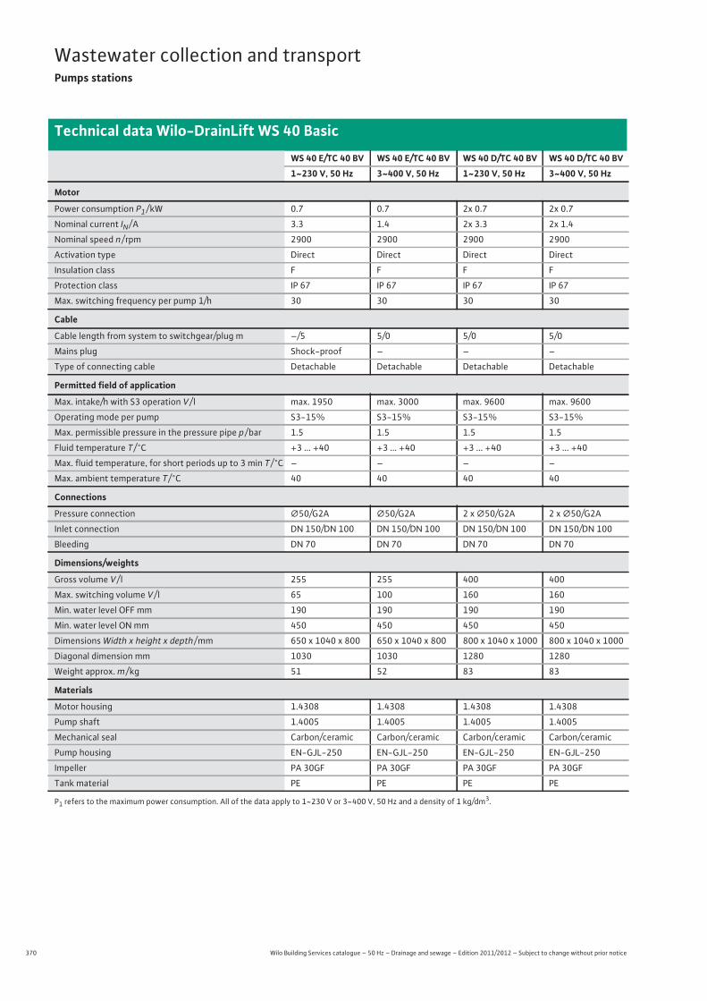
370 Wilo Building Services catalogue – 50 Hz – Drainage and sewage – Edition 2011/2012 – Subject to change without prior notice
Wastewater collection and transportPumps stations
Technical data Wilo-DrainLift WS 40 Basic
WS 40 E/TC 40 BV WS 40 E/TC 40 BV WS 40 D/TC 40 BV WS 40 D/TC 40 BV1~230 V, 50 Hz 3~400 V, 50 Hz 1~230 V, 50 Hz 3~400 V, 50 Hz
Motor
Power consumption P1 / kW 0.7 0.7 2x 0.7 2x 0.7
Nominal current IN / A 3.3 1.4 2x 3.3 2x 1.4
Nominal speed n / rpm 2900 2900 2900 2900
Activation type Direct Direct Direct Direct
Insulation class F F F F
Protection class IP 67 IP 67 IP 67 IP 67
Max. switching frequency per pump 1/h 30 30 30 30
Cable
Cable length from system to switchgear/plug m –/5 5/0 5/0 5/0
Mains plug Shock-proof – – –
Type of connecting cable Detachable Detachable Detachable Detachable
Permitted field of application
Max. intake/h with S3 operation V / l max. 1950 max. 3000 max. 9600 max. 9600
Operating mode per pump S3-15% S3-15% S3-15% S3-15%
Max. permissible pressure in the pressure pipe p / bar 1.5 1.5 1.5 1.5
Fluid temperature T / °C +3 ... +40 +3 ... +40 +3 ... +40 +3 ... +40
Max. fluid temperature, for short periods up to 3 min T / °C – – – –
Max. ambient temperature T / °C 40 40 40 40
Connections
Pressure connection �50/G2A �50/G2A 2 x �50/G2A 2 x �50/G2A
Inlet connection DN 150/DN 100 DN 150/DN 100 DN 150/DN 100 DN 150/DN 100
Bleeding DN 70 DN 70 DN 70 DN 70
Dimensions/weights
Gross volume V / l 255 255 400 400
Max. switching volume V / l 65 100 160 160
Min. water level OFF mm 190 190 190 190
Min. water level ON mm 450 450 450 450
Dimensions Width x height x depth / mm 650 x 1040 x 800 650 x 1040 x 800 800 x 1040 x 1000 800 x 1040 x 1000
Diagonal dimension mm 1030 1030 1280 1280
Weight approx. m / kg 51 52 83 83
Materials
Motor housing 1.4308 1.4308 1.4308 1.4308
Pump shaft 1.4005 1.4005 1.4005 1.4005
Mechanical seal Carbon/ceramic Carbon/ceramic Carbon/ceramic Carbon/ceramic
Pump housing EN-GJL-250 EN-GJL-250 EN-GJL-250 EN-GJL-250
Impeller PA 30GF PA 30GF PA 30GF PA 30GF
Tank material PE PE PE PE
P1 refers to the maximum power consumption. All of the data apply to 1~230 V or 3~400 V, 50 Hz and a density of 1 kg/dm3.
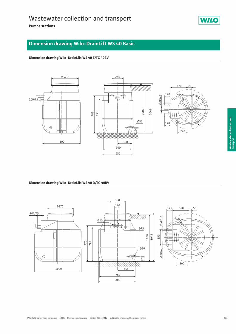
371
Wastewater collection and transportPumps stations
Wilo Building Services catalogue – 50 Hz – Drainage and sewage – Edition 2011/2012 – Subject to change without prior notice
Dimension drawing Wilo-DrainLift WS 40 Basic
Was
tew
ater
col
lect
ion
and
tran
spor
t
Dimension drawing Wilo-DrainLift WS 40 E/TC 40BV
Dimension drawing Wilo-DrainLift WS 40 D/TC 40BV
800
Ø570 240
600
650
300
785
735
1000
1042
Ø50
120
Ø50
/G 2
100/75
120
120
370 75
220
Ø1030
Ø570
1000
350
120
Ø63
Ø75
355
765
800
Ø50
120
770
745 10
0010
42
350
125
100/75
360 50
300
Ø50
/G2
Ø50
/G2
Ø1280
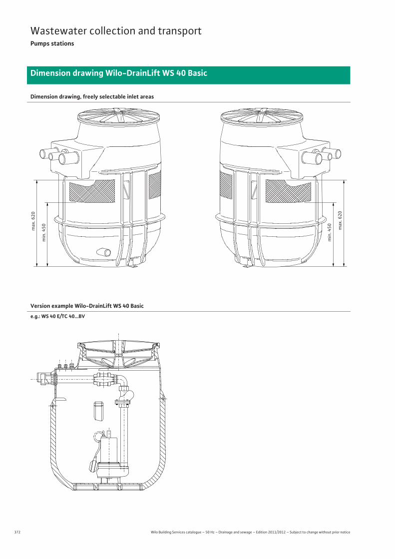
372 Wilo Building Services catalogue – 50 Hz – Drainage and sewage – Edition 2011/2012 – Subject to change without prior notice
Wastewater collection and transportPumps stations
Dimension drawing Wilo-DrainLift WS 40 Basic
Dimension drawing, freely selectable inlet areas
min
. 450m
ax. 6
20
min
. 450 m
ax. 6
20
Version example Wilo-DrainLift WS 40 Basic
e.g.: WS 40 E/TC 40...BV
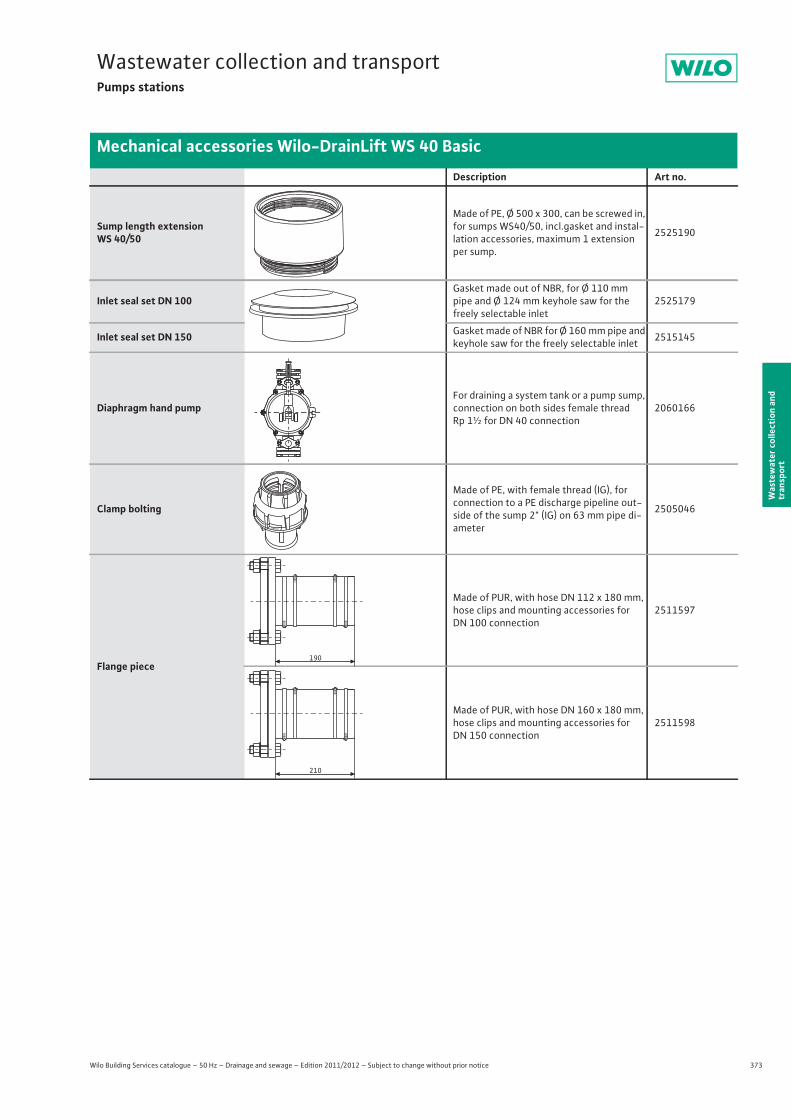
373
Wastewater collection and transportPumps stations
Wilo Building Services catalogue – 50 Hz – Drainage and sewage – Edition 2011/2012 – Subject to change without prior notice
Mechanical accessories Wilo-DrainLift WS 40 Basic
Was
tew
ater
col
lect
ion
and
tran
spor
t
Description Art no.
Sump length extension WS 40/50
Made of PE, Ø 500 x 300, can be screwed in, for sumps WS40/50, incl.gasket and instal-lation accessories, maximum 1 extension per sump.
2525190
Inlet seal set DN 100Gasket made out of NBR, for Ø 110 mm pipe and Ø 124 mm keyhole saw for the freely selectable inlet
2525179
Inlet seal set DN 150 Gasket made of NBR for Ø 160 mm pipe and keyhole saw for the freely selectable inlet 2515145
Diaphragm hand pumpFor draining a system tank or a pump sump, connection on both sides female thread Rp 1½ for DN 40 connection
2060166
Clamp bolting
Made of PE, with female thread (IG), for connection to a PE discharge pipeline out-side of the sump 2" (IG) on 63 mm pipe di-ameter
2505046
Flange piece
Made of PUR, with hose DN 112 x 180 mm, hose clips and mounting accessories for DN 100 connection
2511597
Made of PUR, with hose DN 160 x 180 mm, hose clips and mounting accessories for DN 150 connection
2511598
PLASSIM
190
210
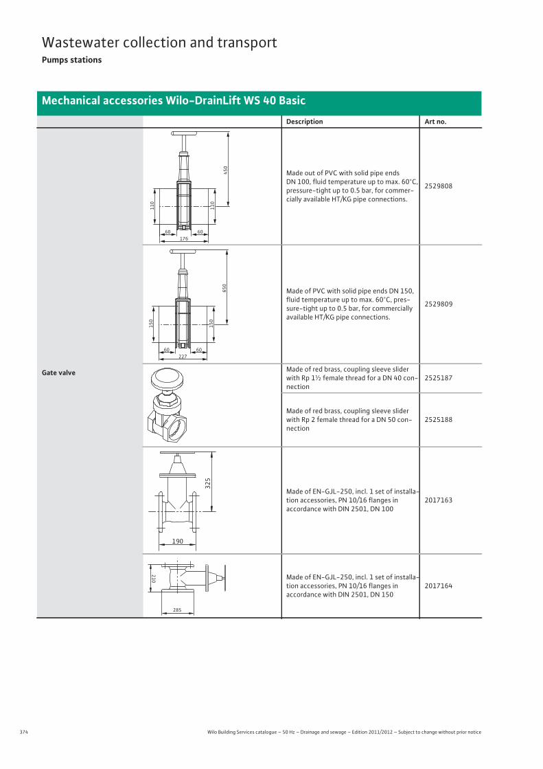
374 Wilo Building Services catalogue – 50 Hz – Drainage and sewage – Edition 2011/2012 – Subject to change without prior notice
Wastewater collection and transportPumps stations
Mechanical accessories Wilo-DrainLift WS 40 Basic
Gate valve
Made out of PVC with solid pipe ends DN 100, fluid temperature up to max. 60°C, pressure-tight up to 0.5 bar, for commer-cially available HT/KG pipe connections.
2529808
Made of PVC with solid pipe ends DN 150, fluid temperature up to max. 60°C, pres-sure-tight up to 0.5 bar, for commercially available HT/KG pipe connections.
2529809
Made of red brass, coupling sleeve slider with Rp 1½ female thread for a DN 40 con-nection
2525187
Made of red brass, coupling sleeve slider with Rp 2 female thread for a DN 50 con-nection
2525188
Made of EN-GJL-250, incl. 1 set of installa-tion accessories, PN 10/16 flanges inaccordance with DIN 2501, DN 100
2017163
Made of EN-GJL-250, incl. 1 set of installa-tion accessories, PN 10/16 flanges inaccordance with DIN 2501, DN 150
2017164
Description Art no.
60 60
110
110
450
176
60 60
150
150
650
227
325
190
210
285
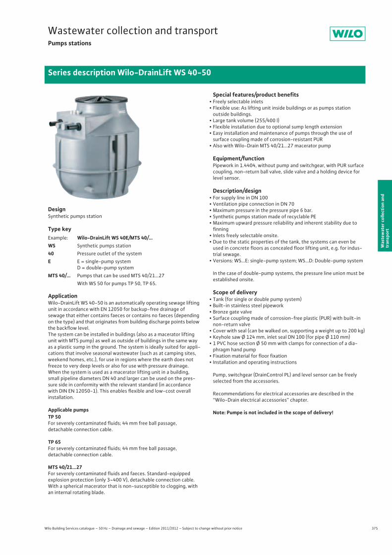
375
Wastewater collection and transportPumps stations
Wilo Building Services catalogue – 50 Hz – Drainage and sewage – Edition 2011/2012 – Subject to change without prior notice
Series description Wilo-DrainLift WS 40-50
Was
tew
ater
col
lect
ion
and
tran
spor
t
DesignSynthetic pumps station
Type key
ApplicationWilo-DrainLift WS 40-50 is an automatically operating sewage lifting unit in accordance with EN 12050 for backup-free drainage ofsewage that either contains faeces or contains no faeces (depending on the type) and that originates from building discharge points below the backflow level.The system can be installed in buildings (also as a macerator lifting unit with MTS pump) as well as outside of buildings in the same way as a plastic sump in the ground. The system is ideally suited for appli-cations that involve seasonal wastewater (such as at camping sites, weekend homes, etc.), for use in regions where the earth does not freeze to very deep levels or also for use with pressure drainage.When the system is used as a macerator lifting unit in a building, small pipeline diameters DN 40 and larger can be used on the pres-sure side in conformity with the relevant standard (in accordance with DIN EN 12050-1). This enables flexible and low-cost overallinstallation.
Applicable pumpsTP 50For severely contaminated fluids; 44 mm free ball passage,detachable connection cable.
TP 65For severely contaminated fluids; 44 mm free ball passage,detachable connection cable.
MTS 40/21...27For severely contaminated fluids and faeces. Standard-equippedexplosion protection (only 3~400 V), detachable connection cable. With a spherical macerator that is non-susceptible to clogging, with an internal rotating blade.
Special features/product benefits• Freely selectable inlets• Flexible use: As lifting unit inside buildings or as pumps station
outside buildings.• Large tank volume (255/400 l)• Flexible installation due to optional sump length extension• Easy installation and maintenance of pumps through the use of
surface coupling made of corrosion-resistant PUR• Also with Wilo-Drain MTS 40/21...27 macerator pump
Equipment/functionPipework in 1.4404, without pump and switchgear, with PUR surface coupling, non-return ball valve, slide valve and a holding device for level sensor.
Description/design• For supply line in DN 100• Ventilation pipe connection in DN 70• Maximum pressure in the pressure pipe 6 bar.• Synthetic pumps station made of recyclable PE• Maximum upward pressure reliability and inherent stability due to
finning• Inlets freely selectable onsite.• Due to the static properties of the tank, the systems can even be
used in concrete floors as concealed floor lifting unit, e.g. for indus-trial sewage.
• Versions: WS...E: single-pump system; WS...D: Double-pump system
In the case of double-pump systems, the pressure line union must be established onsite.
Scope of delivery• Tank (for single or double pump system)• Built-in stainless steel pipework• Bronze gate valve• Surface coupling made of corrosion-free plastic (PUR) with built-in
non-return valve • Cover with seal (can be walked on, supporting a weight up to 200 kg)• Keyhole saw Ø 124 mm, inlet seal DN 100 (for pipe Ø 110 mm)• 1 PVC hose section Ø 50 mm with clamps for connection of a dia-
phragm hand pump• Fixation material for floor fixation• Installation and operating instructions
Pump, switchgear (DrainControl PL) and level sensor can be freelyselected from the accessories.
Recommendations for electrical accessories are described in the “Wilo-Drain electrical accessories” chapter.
Note: Pumpe is not included in the scope of delivery!
Example: Wilo-DrainLift WS 40E/MTS 40/...WS Synthetic pumps station40 Pressure outlet of the systemE E = single-pump system
D = double-pump systemMTS 40/... Pumps that can be used MTS 40/21...27
With WS 50 for pumps TP 50, TP 65.
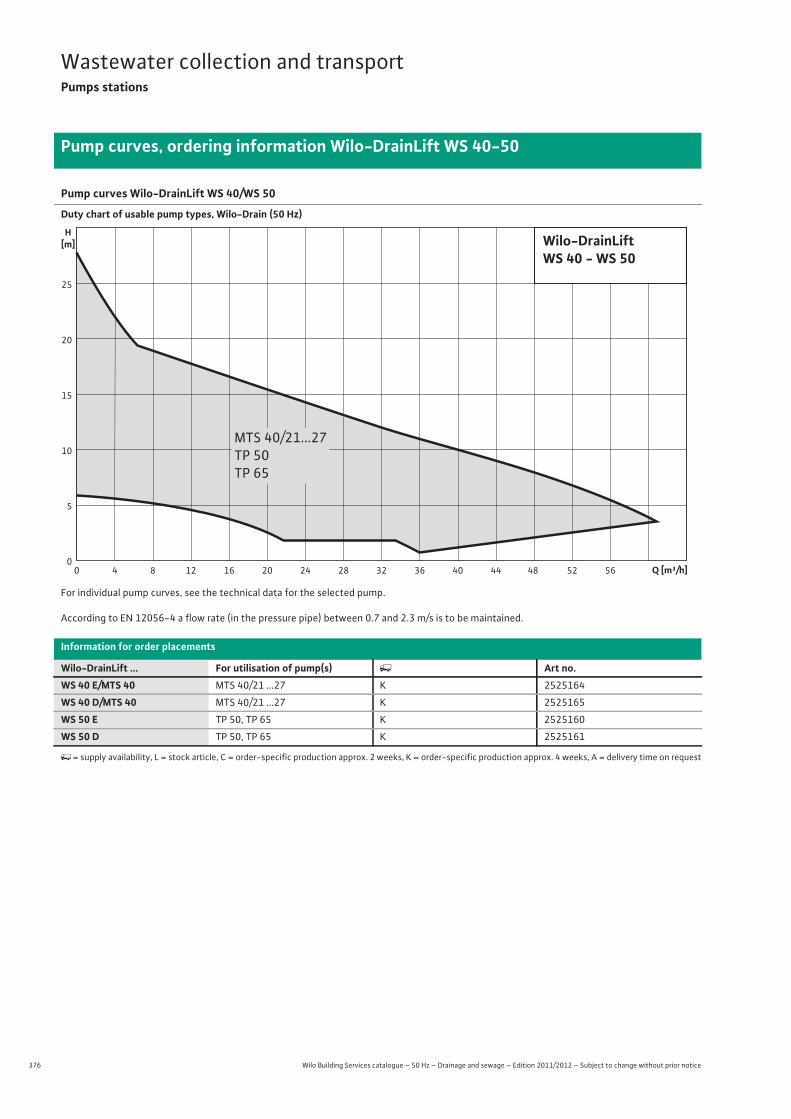
376 Wilo Building Services catalogue – 50 Hz – Drainage and sewage – Edition 2011/2012 – Subject to change without prior notice
Wastewater collection and transportPumps stations
Pump curves, ordering information Wilo-DrainLift WS 40-50
Pump curves Wilo-DrainLift WS 40/WS 50
Duty chart of usable pump types, Wilo-Drain (50 Hz)
For individual pump curves, see the technical data for the selected pump.
According to EN 12056-4 a flow rate (in the pressure pipe) between 0.7 and 2.3 m/s is to be maintained.
Information for order placements
Wilo-DrainLift ... For utilisation of pump(s) � Art no.WS 40 E/MTS 40 MTS 40/21 ...27 K 2525164
WS 40 D/MTS 40 MTS 40/21 ...27 K 2525165
WS 50 E TP 50, TP 65 K 2525160
WS 50 D TP 50, TP 65 K 2525161
�= supply availability, L = stock article, C = order-specific production approx. 2 weeks, K = order-specific production approx. 4 weeks, A = delivery time on request
H[m]
0
25
20
15
10
5
Q [m³/h]8 12 16 20 24 28 32 36 40 44 48 52 5640
Wilo-DrainLiftWS 40 - WS 50
MTS 40/21...27TP 50TP 65
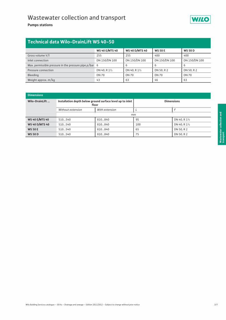
377
Wastewater collection and transportPumps stations
Wilo Building Services catalogue – 50 Hz – Drainage and sewage – Edition 2011/2012 – Subject to change without prior notice
Technical data Wilo-DrainLift WS 40-50
Was
tew
ater
col
lect
ion
and
tran
spor
t
WS 40 E/MTS 40 WS 40 D/MTS 40 WS 50 E WS 50 DGross volume V / l 255 255 400 400
Inlet connection DN 150/DN 100 DN 150/DN 100 DN 150/DN 100 DN 150/DN 100
Max. permissible pressure in the pressure pipe p / bar 6 6 6 6
Pressure connection DN 40, R 1½ DN 40, R 1½ DN 50, R 2 DN 50, R 2
Bleeding DN 70 DN 70 DN 70 DN 70
Weight approx. m / kg 43 63 46 63
Dimensions
Wilo-DrainLift ... Installation depth below ground surface level up to inlet floor
Dimensions
Without extension With extension L F
mm
WS 40 E/MTS 40 510...540 810...840 95 DN 40, R 1½
WS 40 D/MTS 40 510...540 810...840 100 DN 40, R 1½
WS 50 E 510...540 810...840 65 DN 50, R 2
WS 50 D 510...540 810...840 75 DN 50, R 2
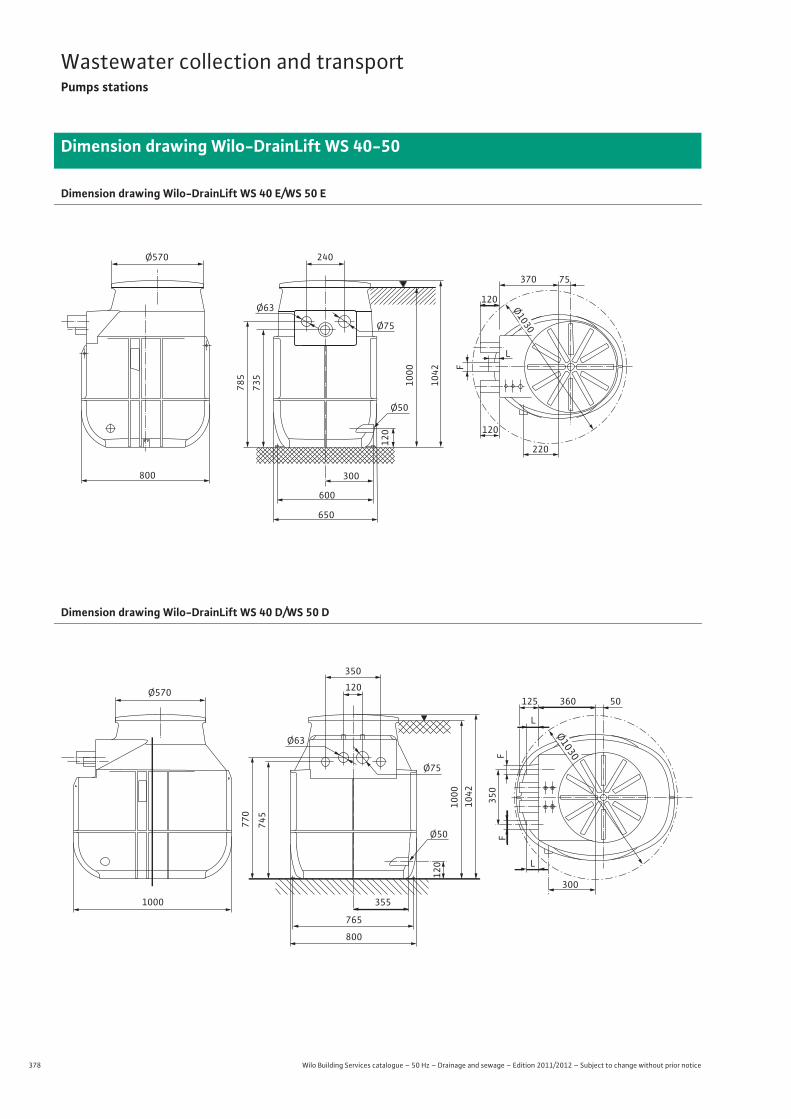
378 Wilo Building Services catalogue – 50 Hz – Drainage and sewage – Edition 2011/2012 – Subject to change without prior notice
Wastewater collection and transportPumps stations
Dimension drawing Wilo-DrainLift WS 40-50
Dimension drawing Wilo-DrainLift WS 40 E/WS 50 E
Dimension drawing Wilo-DrainLift WS 40 D/WS 50 D
800
Ø570 240
600
650
300
785
735
1000
1042
Ø50
120
F
L
120
120
370 75
220
Ø63
Ø75
Ø1030
Ø570
1000
350
120
Ø63
Ø75
355
765
800
Ø50
120
770
745
1000
1042
350
FF
125
L
L
360 50
300
Ø1030
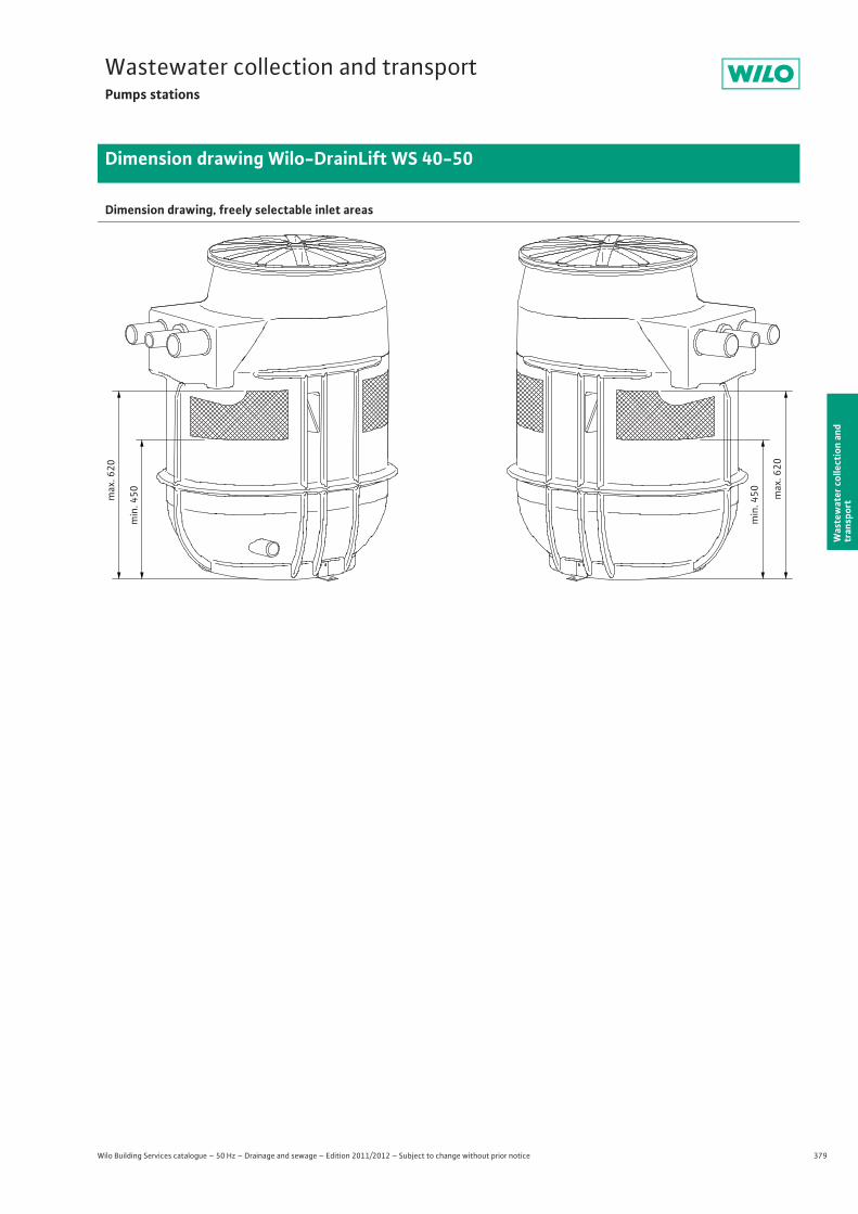
379
Wastewater collection and transportPumps stations
Wilo Building Services catalogue – 50 Hz – Drainage and sewage – Edition 2011/2012 – Subject to change without prior notice
Dimension drawing Wilo-DrainLift WS 40-50
Was
tew
ater
col
lect
ion
and
tran
spor
t
Dimension drawing, freely selectable inlet areas
min
. 450m
ax. 6
20
min
. 450 m
ax. 6
20
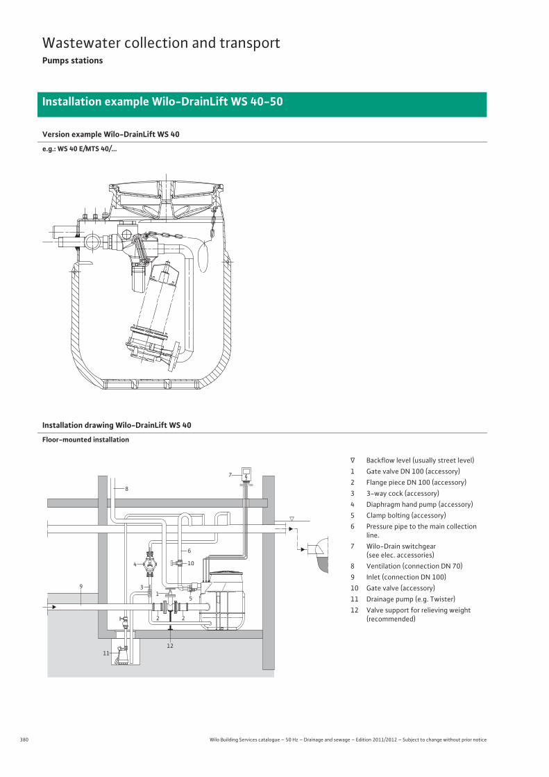
380 Wilo Building Services catalogue – 50 Hz – Drainage and sewage – Edition 2011/2012 – Subject to change without prior notice
Wastewater collection and transportPumps stations
Installation example Wilo-DrainLift WS 40-50
Version example Wilo-DrainLift WS 40
e.g.: WS 40 E/MTS 40/...
Installation drawing Wilo-DrainLift WS 40
Floor-mounted installation
8
7
4 10
11
31
2
5
9
6
2
12
� Backflow level (usually street level)1 Gate valve DN 100 (accessory)2 Flange piece DN 100 (accessory)3 3-way cock (accessory)4 Diaphragm hand pump (accessory)5 Clamp bolting (accessory)6 Pressure pipe to the main collection
line.7 Wilo-Drain switchgear
(see elec. accessories)8 Ventilation (connection DN 70)9 Inlet (connection DN 100)10 Gate valve (accessory)11 Drainage pump (e.g. Twister)12 Valve support for relieving weight
(recommended)
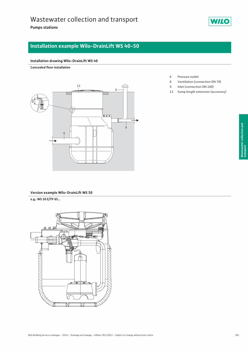
381
Wastewater collection and transportPumps stations
Wilo Building Services catalogue – 50 Hz – Drainage and sewage – Edition 2011/2012 – Subject to change without prior notice
Installation example Wilo-DrainLift WS 40-50
Was
tew
ater
col
lect
ion
and
tran
spor
t
Installation drawing Wilo-DrainLift WS 40
Concealed floor installation
Version example Wilo-DrainLift WS 50
e.g.: WS 50 E/TP 65...
50
8
6
13
9
6 Pressure outlet8 Ventilation (connection DN 70)9 Inlet (connection DN 100)13 Sump length extension (accessory)
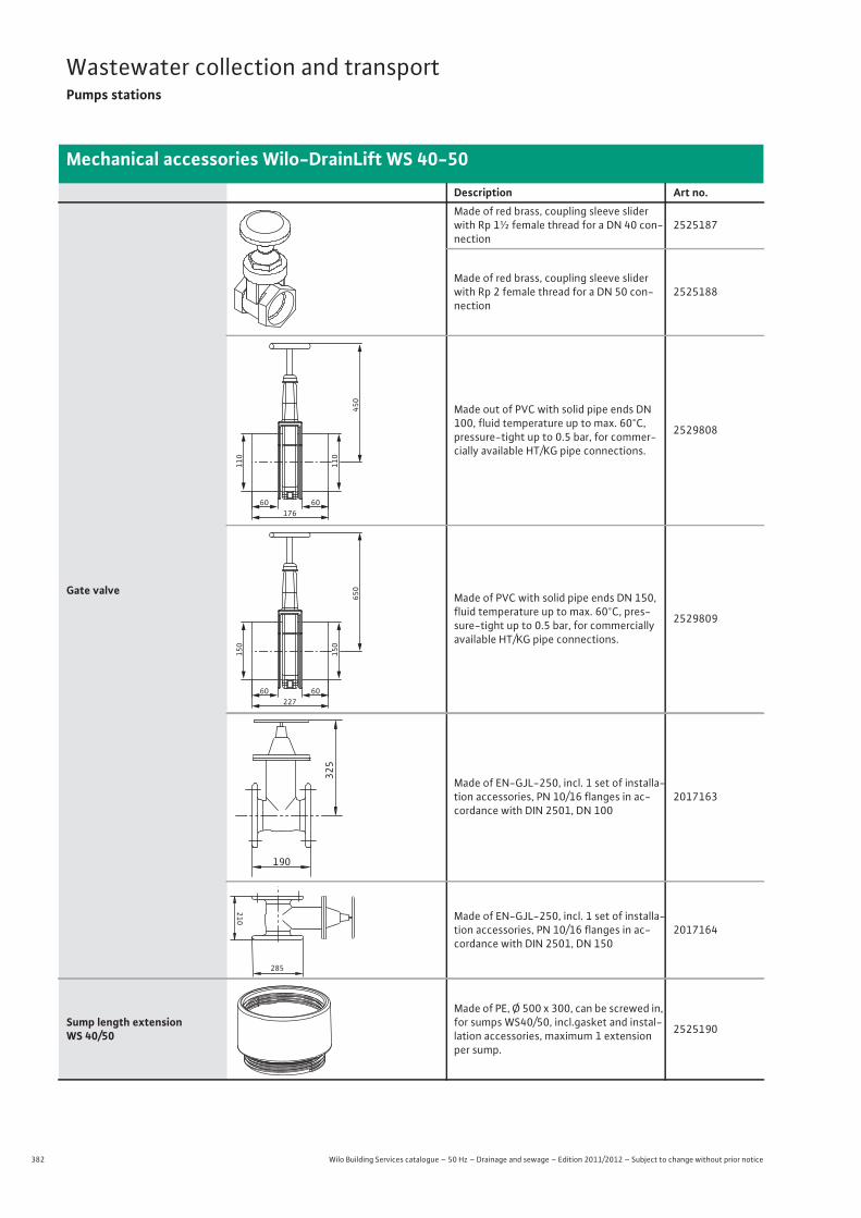
382 Wilo Building Services catalogue – 50 Hz – Drainage and sewage – Edition 2011/2012 – Subject to change without prior notice
Wastewater collection and transportPumps stations
Mechanical accessories Wilo-DrainLift WS 40-50
Description Art no.
Gate valve
Made of red brass, coupling sleeve slider with Rp 1½ female thread for a DN 40 con-nection
2525187
Made of red brass, coupling sleeve slider with Rp 2 female thread for a DN 50 con-nection
2525188
Made out of PVC with solid pipe ends DN 100, fluid temperature up to max. 60°C, pressure-tight up to 0.5 bar, for commer-cially available HT/KG pipe connections.
2529808
Made of PVC with solid pipe ends DN 150, fluid temperature up to max. 60°C, pres-sure-tight up to 0.5 bar, for commercially available HT/KG pipe connections.
2529809
Made of EN-GJL-250, incl. 1 set of installa-tion accessories, PN 10/16 flanges in ac-cordance with DIN 2501, DN 100
2017163
Made of EN-GJL-250, incl. 1 set of installa-tion accessories, PN 10/16 flanges in ac-cordance with DIN 2501, DN 150
2017164
Sump length extension WS 40/50
Made of PE, Ø 500 x 300, can be screwed in, for sumps WS40/50, incl.gasket and instal-lation accessories, maximum 1 extension per sump.
2525190
60 60
110
110
450
176
60 60
150
150
650
227
325
190
210
285
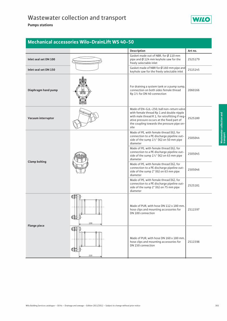
383
Wastewater collection and transportPumps stations
Wilo Building Services catalogue – 50 Hz – Drainage and sewage – Edition 2011/2012 – Subject to change without prior notice
Mechanical accessories Wilo-DrainLift WS 40-50
Was
tew
ater
col
lect
ion
and
tran
spor
t
Inlet seal set DN 100Gasket made out of NBR, for Ø 110 mm pipe and Ø 124 mm keyhole saw for the freely selectable inlet
2525179
Inlet seal set DN 150 Gasket made of NBR for Ø 160 mm pipe and keyhole saw for the freely selectable inlet 2515145
Diaphragm hand pumpFor draining a system tank or a pump sump, connection on both sides female thread Rp 1½ for DN 40 connection
2060166
Vacuum interruptor
Made of EN-GJL-250, ball non-return valve with female thread Rp 1 and double nipple with male thread R 1, for retrofitting if neg-ative pressure occurs at the fixed part of the coupling towards the pressure pipe on-site
2525180
Clamp bolting
Made of PE, with female thread (IG), for connection to a PE discharge pipeline out-side of the sump 1½" (IG) on 50 mm pipe diameter
2505044
Made of PE, with female thread (IG), for connection to a PE discharge pipeline out-side of the sump 1½" (IG) on 63 mm pipe diameter
2505045
Made of PE, with female thread (IG), for connection to a PE discharge pipeline out-side of the sump 2" (IG) on 63 mm pipediameter
2505046
Made of PE, with female thread (IG), for connection to a PE discharge pipeline out-side of the sump 2" (IG) on 75 mm pipediameter
2525181
Flange piece
Made of PUR, with hose DN 112 x 180 mm, hose clips and mounting accessories for DN 100 connection
2511597
Made of PUR, with hose DN 160 x 180 mm, hose clips and mounting accessories for DN 150 connection
2511598
Description Art no.
PLASSIM
190
210
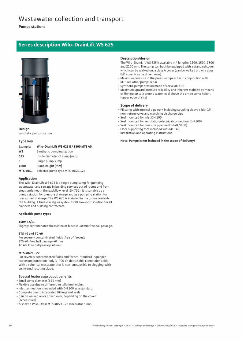
384 Wilo Building Services catalogue – 50 Hz – Drainage and sewage – Edition 2011/2012 – Subject to change without prior notice
Wastewater collection and transportPumps stations
Series description Wilo-DrainLift WS 625
DesignSynthetic pumps station
Type key
ApplicationThe Wilo-DrainLift WS 625 is a single pump sump for pumping wastewater and sewage in building services out of rooms and from areas underneath the backflow level (EN 752). It is suitable as a pumps station for pressure drainage and as a pumping station for pressurised drainage. The WS 625 is installed in the ground outside the building. A time-saving, easy-to-install, low-cost solution for all planners and building contractors.
Applicable pump types
TMW 32/11Slightly contaminated fluids (free of faeces), 10 mm free ball passage.
STS 40 and TC 40For severely contaminated fluids (free of faeces);STS 40: Free ball passage 40 mmTC 40: Free ball passage 40 mm
MTS 40/21...27For severely contaminated fluids and faeces. Standard-equippedexplosion protection (only 3~400 V), detachable connection cable. With a spherical macerator that is non-susceptible to clogging, with an internal rotating blade.
Special features/product benefits• Small sump diameter (625 mm)• Flexible use due to different installation heights• Inlet connection is included with DN 100 as a standard• Complete due to integrated fittings and seals• Can be walked on or driven over, depending on the cover
(accessories)• Also with Wilo-Drain MTS 40/21...27 macerator pump
Description/designThe Wilo-DrainLift WS 625 is available in 4 lengths: 1200, 1500, 1800 and 2100 mm. The sump can both be equipped with a standard cover which can be walked on, a class A cover (can be walked on) or a class B/D cover (can be driven over).
• Maximum pressure in the pressure pipe 6 bar in conjunction with MTS 40, other pumps 4 bar
• Synthetic pumps station made of recyclable PE• Maximum upward pressure reliability and inherent stability by means
of finning up to a ground water level above the entire sump height (upper edge of site)
Scope of delivery• PE sump with internal pipework including coupling sleeve slider 1¼",
non-return valve and matching discharge pipe• Seal mounted for inlet DN 100• Seal mounted for ventilation/electrical connection (DN 100).• Seal mounted for pressure pipeline (DN 40 / Ø50).• Floor supporting foot included with MTS 40• Installation and operating instructions.
Note: Pumpe is not included in the scope of delivery!
Example: Wilo-DrainLift WS 625 E / 1800 MTS 40WS Synthetic pumping station625 Inside diameter of sump [mm]E Single pump sump1800 Sump height [mm]MTS 40/... Selected pump type MTS 40/21...27
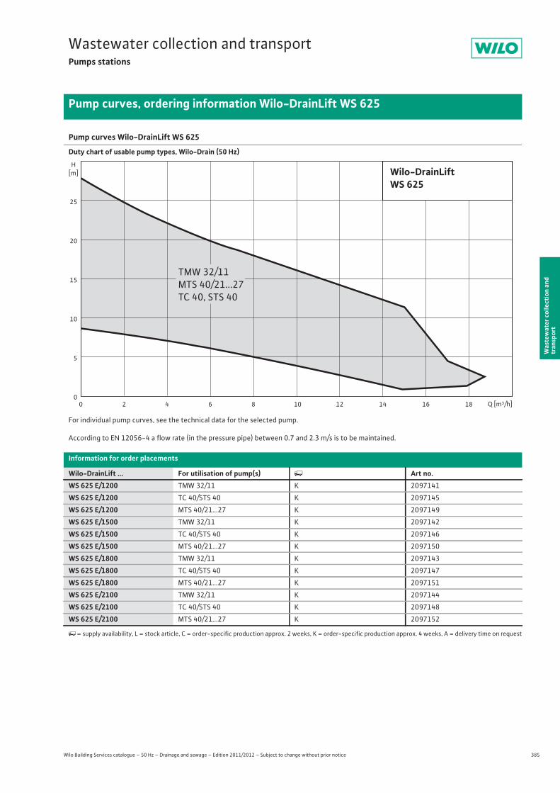
385
Wastewater collection and transportPumps stations
Wilo Building Services catalogue – 50 Hz – Drainage and sewage – Edition 2011/2012 – Subject to change without prior notice
Pump curves, ordering information Wilo-DrainLift WS 625
Was
tew
ater
col
lect
ion
and
tran
spor
t
Pump curves Wilo-DrainLift WS 625
Duty chart of usable pump types, Wilo-Drain (50 Hz)
For individual pump curves, see the technical data for the selected pump.
According to EN 12056-4 a flow rate (in the pressure pipe) between 0.7 and 2.3 m/s is to be maintained.
Information for order placements
Wilo-DrainLift ... For utilisation of pump(s) � Art no.WS 625 E/1200 TMW 32/11 K 2097141
WS 625 E/1200 TC 40/STS 40 K 2097145
WS 625 E/1200 MTS 40/21...27 K 2097149
WS 625 E/1500 TMW 32/11 K 2097142
WS 625 E/1500 TC 40/STS 40 K 2097146
WS 625 E/1500 MTS 40/21...27 K 2097150
WS 625 E/1800 TMW 32/11 K 2097143
WS 625 E/1800 TC 40/STS 40 K 2097147
WS 625 E/1800 MTS 40/21...27 K 2097151
WS 625 E/2100 TMW 32/11 K 2097144
WS 625 E/2100 TC 40/STS 40 K 2097148
WS 625 E/2100 MTS 40/21...27 K 2097152
�= supply availability, L = stock article, C = order-specific production approx. 2 weeks, K = order-specific production approx. 4 weeks, A = delivery time on request
H[m]
0
25
20
15
10
5
Q [m³/h]6 8 10 12 14 16 18420
Wilo-DrainLiftWS 625
TMW 32/11MTS 40/21...27TC 40, STS 40
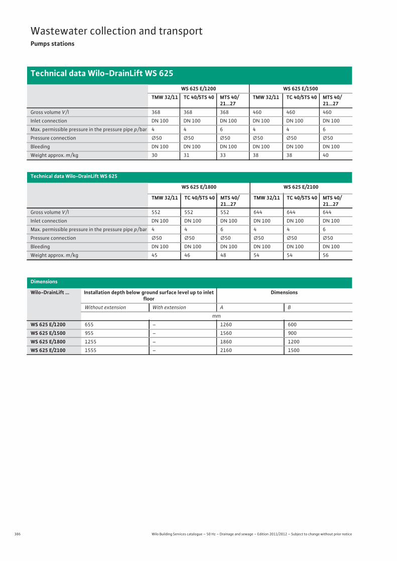
386 Wilo Building Services catalogue – 50 Hz – Drainage and sewage – Edition 2011/2012 – Subject to change without prior notice
Wastewater collection and transportPumps stations
Technical data Wilo-DrainLift WS 625
WS 625 E/1200 WS 625 E/1500TMW 32/11 TC 40/STS 40 MTS 40/
21...27TMW 32/11 TC 40/STS 40 MTS 40/
21...27Gross volume V / l 368 368 368 460 460 460
Inlet connection DN 100 DN 100 DN 100 DN 100 DN 100 DN 100
Max. permissible pressure in the pressure pipe p / bar 4 4 6 4 4 6
Pressure connection �50 �50 �50 �50 �50 �50
Bleeding DN 100 DN 100 DN 100 DN 100 DN 100 DN 100
Weight approx. m / kg 30 31 33 38 38 40
Technical data Wilo-DrainLift WS 625
WS 625 E/1800 WS 625 E/2100
TMW 32/11 TC 40/STS 40 MTS 40/21...27
TMW 32/11 TC 40/STS 40 MTS 40/21...27
Gross volume V / l 552 552 552 644 644 644
Inlet connection DN 100 DN 100 DN 100 DN 100 DN 100 DN 100
Max. permissible pressure in the pressure pipe p / bar 4 4 6 4 4 6
Pressure connection �50 �50 �50 �50 �50 �50
Bleeding DN 100 DN 100 DN 100 DN 100 DN 100 DN 100
Weight approx. m / kg 45 46 48 54 54 56
Dimensions
Wilo-DrainLift ... Installation depth below ground surface level up to inlet floor
Dimensions
Without extension With extension A B
mm
WS 625 E/1200 655 – 1260 600
WS 625 E/1500 955 – 1560 900
WS 625 E/1800 1255 – 1860 1200
WS 625 E/2100 1555 – 2160 1500
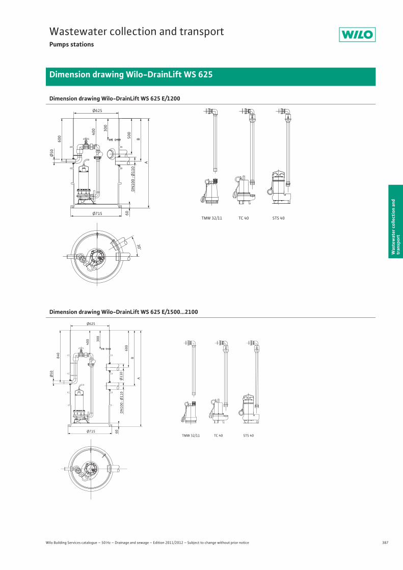
387
Wastewater collection and transportPumps stations
Wilo Building Services catalogue – 50 Hz – Drainage and sewage – Edition 2011/2012 – Subject to change without prior notice
Dimension drawing Wilo-DrainLift WS 625
Was
tew
ater
col
lect
ion
and
tran
spor
t
Dimension drawing Wilo-DrainLift WS 625 E/1200
Dimension drawing Wilo-DrainLift WS 625 E/1500...2100
Ø625
600
Ø50
400 300
Ø715 60DN
100
: Ø110
500
B
A
30°
TMW 32/11 STS 40TC 40
Ø625
840
Ø50
400 300
Ø715 60DN
100
: Ø110
AØ110
600
B
TMW 32/11 STS 40TC 40
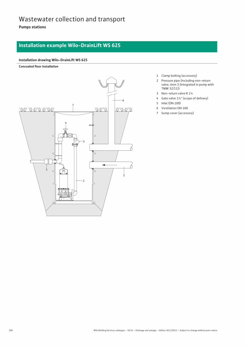
388 Wilo Building Services catalogue – 50 Hz – Drainage and sewage – Edition 2011/2012 – Subject to change without prior notice
Wastewater collection and transportPumps stations
Installation example Wilo-DrainLift WS 625
Installation drawing Wilo-DrainLift WS 625
Concealed floor installation
6
3
2
5
7
4
1
1 Clamp bolting (accessory)2 Pressure pipe (including non-return
valve, item 3 (integrated in pump with TMW 32/11))
3 Non-return valve R 1¼4 Gate valve 1¼" (scope of delivery)5 Inlet (DN 100)6 Ventilation DN 1007 Sump cover (accessory)
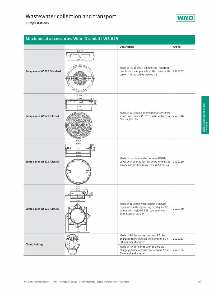
389
Wastewater collection and transportPumps stations
Wilo Building Services catalogue – 50 Hz – Drainage and sewage – Edition 2011/2012 – Subject to change without prior notice
Mechanical accessories Wilo-DrainLift WS 625
Was
tew
ater
col
lect
ion
and
tran
spor
t
Description Art no.
Sump cover WS625 StandardMade of PE, Ø 692 x 30 mm, slip-resistant profile on the upper side of the cover, with screws - lock, can be walked on
2525207
Sump cover WS625 Class AMade of cast iron, cover with overlay for PE sumps with inside Ø 625, can be walked on, Class A, EN 124
2525318
Sump cover WS625 Class BMade of cast iron with concrete (BEGU), cover with overlay for PE sumps with inside Ø 625, can be driven over, Class B, EN 124
2525319
Sump cover WS625 Class D
Made of cast iron with concrete (BEGU), cover with self-supporting overlay for PE sumps with inside Ø 625, can be driven over, Class D, EN 124
2525320
Clamp bolting
Made of PP, for connection to a PE dis-charge pipeline outside the sump on 50 x 50 mm pipe diameter
2525183
Made of PP, for connection to a PE dis-charge pipeline outside the sump on 50 x 63 mm pipe diameter
2525184
Ø 692
Ø 615 7026
100
Ø 648Ø 669
Ø 605Ø 654
Ø 670Ø 648
Ø 604Ø 654
26100
Ø 707Ø 684Ø 680
R331Ø 610
Ø 665
50
60
160
8101107
PLASSIM
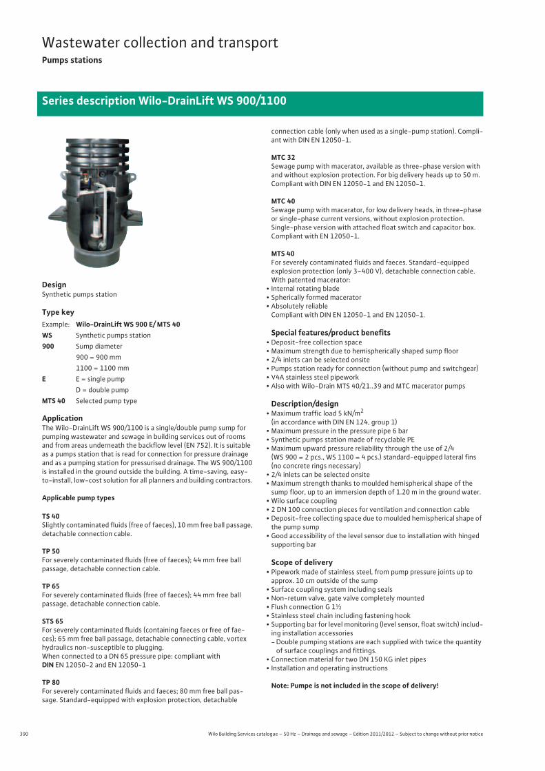
390 Wilo Building Services catalogue – 50 Hz – Drainage and sewage – Edition 2011/2012 – Subject to change without prior notice
Wastewater collection and transportPumps stations
Series description Wilo-DrainLift WS 900/1100
DesignSynthetic pumps station
Type key
ApplicationThe Wilo-DrainLift WS 900/1100 is a single/double pump sump for pumping wastewater and sewage in building services out of rooms and from areas underneath the backflow level (EN 752). It is suitable as a pumps station that is read for connection for pressure drainage and as a pumping station for pressurised drainage. The WS 900/1100 is installed in the ground outside the building. A time-saving, easy-to-install, low-cost solution for all planners and building contractors.
Applicable pump types
TS 40Slightly contaminated fluids (free of faeces), 10 mm free ball passage, detachable connection cable.
TP 50For severely contaminated fluids (free of faeces); 44 mm free ball passage, detachable connection cable.
TP 65For severely contaminated fluids (free of faeces); 44 mm free ball passage, detachable connection cable.
STS 65For severely contaminated fluids (containing faeces or free of fae-ces); 65 mm free ball passage, detachable connecting cable, vortex hydraulics non-susceptible to plugging.When connected to a DN 65 pressure pipe: compliant with DIN EN 12050-2 and EN 12050-1
TP 80For severely contaminated fluids and faeces; 80 mm free ball pas-sage. Standard-equipped with explosion protection, detachable
connection cable (only when used as a single-pump station). Compli-ant with DIN EN 12050-1.
MTC 32Sewage pump with macerator, available as three-phase version with and without explosion protection. For big delivery heads up to 50 m. Compliant with DIN EN 12050-1 and EN 12050-1.
MTC 40Sewage pump with macerator, for low delivery heads, in three-phase or single-phase current versions, without explosion protection.Single-phase version with attached float switch and capacitor box. Compliant with EN 12050-1.
MTS 40For severely contaminated fluids and faeces. Standard-equippedexplosion protection (only 3~400 V), detachable connection cable. With patented macerator:
• Internal rotating blade• Spherically formed macerator• Absolutely reliable
Compliant with DIN EN 12050-1 and EN 12050-1.
Special features/product benefits• Deposit-free collection space• Maximum strength due to hemispherically shaped sump floor• 2/4 inlets can be selected onsite• Pumps station ready for connection (without pump and switchgear)• V4A stainless steel pipework• Also with Wilo-Drain MTS 40/21..39 and MTC macerator pumps
Description/design• Maximum traffic load 5 kN/m2
(in accordance with DIN EN 124, group 1)• Maximum pressure in the pressure pipe 6 bar• Synthetic pumps station made of recyclable PE• Maximum upward pressure reliability through the use of 2/4
(WS 900 = 2 pcs., WS 1100 = 4 pcs.) standard-equipped lateral fins (no concrete rings necessary)
• 2/4 inlets can be selected onsite• Maximum strength thanks to moulded hemispherical shape of the
sump floor, up to an immersion depth of 1.20 m in the ground water.• Wilo surface coupling• 2 DN 100 connection pieces for ventilation and connection cable• Deposit-free collecting space due to moulded hemispherical shape of
the pump sump• Good accessibility of the level sensor due to installation with hinged
supporting bar
Scope of delivery• Pipework made of stainless steel, from pump pressure joints up to approx. 10 cm outside of the sump
• Surface coupling system including seals• Non-return valve, gate valve completely mounted• Flush connection G 1½• Stainless steel chain including fastening hook• Supporting bar for level monitoring (level sensor, float switch) includ-
ing installation accessories-Double pumping stations are each supplied with twice the quantity
of surface couplings and fittings.• Connection material for two DN 150 KG inlet pipes• Installation and operating instructions
Note: Pumpe is not included in the scope of delivery!
Example: Wilo-DrainLift WS 900 E/ MTS 40WS Synthetic pumps station 900 Sump diameter
900 = 900 mm1100 = 1100 mm
E E = single pumpD = double pump
MTS 40 Selected pump type
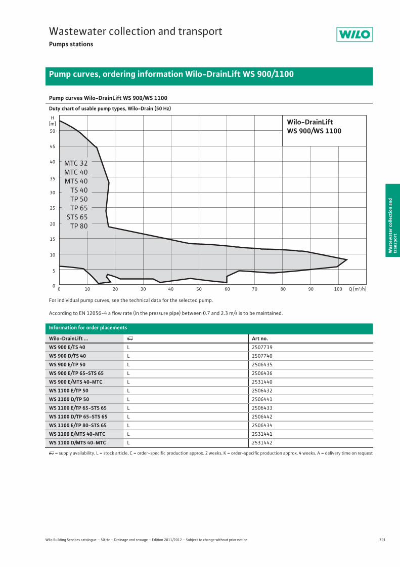
391
Wastewater collection and transportPumps stations
Wilo Building Services catalogue – 50 Hz – Drainage and sewage – Edition 2011/2012 – Subject to change without prior notice
Pump curves, ordering information Wilo-DrainLift WS 900/1100
Was
tew
ater
col
lect
ion
and
tran
spor
t
Pump curves Wilo-DrainLift WS 900/WS 1100
Duty chart of usable pump types, Wilo-Drain (50 Hz)
For individual pump curves, see the technical data for the selected pump.
According to EN 12056-4 a flow rate (in the pressure pipe) between 0.7 and 2.3 m/s is to be maintained.
Information for order placements
Wilo-DrainLift ... � Art no.WS 900 E/TS 40 L 2507739
WS 900 D/TS 40 L 2507740
WS 900 E/TP 50 L 2506435
WS 900 E/TP 65-STS 65 L 2506436
WS 900 E/MTS 40-MTC L 2531440
WS 1100 E/TP 50 L 2506432
WS 1100 D/TP 50 L 2506441
WS 1100 E/TP 65-STS 65 L 2506433
WS 1100 D/TP 65-STS 65 L 2506442
WS 1100 E/TP 80-STS 65 L 2506434
WS 1100 E/MTS 40-MTC L 2531441
WS 1100 D/MTS 40-MTC L 2531442
�= supply availability, L = stock article, C = order-specific production approx. 2 weeks, K = order-specific production approx. 4 weeks, A = delivery time on request
Q [m³/h]50 60 70 90 10030 402010 8000
5
10
15
20
25
30
35
40
45
50
H[m] Wilo-DrainLift
WS 900/WS 1100
MTC 32MTC 40MTS 40
TS 40TP 50TP 65STS 65
TP 80
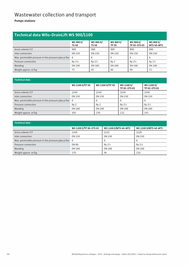
392 Wilo Building Services catalogue – 50 Hz – Drainage and sewage – Edition 2011/2012 – Subject to change without prior notice
Wastewater collection and transportPumps stations
Technical data Wilo-DrainLift WS 900/1100
WS 900 E/TS 40
WS 900 D/TS 40
WS 900 E/TP 50
WS 900 E/TP 65-STS 65
WS 900 E/MTS 40-MTC
Gross volume V / l 900 900 900 900 880
Inlet connection DN 150 DN 150 DN 150 DN 150 DN 150
Max. permissible pressure in the pressure pipe p / bar 6 6 6 6 6
Pressure connection Rp 1½ Rp 1½ Rp 2 Rp 2½ Rp 1½
Bleeding DN 100 DN 100 DN 100 DN 100 DN 100
Weight approx. m / kg 75 95 80 90 72
Technical data
WS 1100 E/TP 50 WS 1100 D/TP 50 WS 1100 E/TP 65-STS 65
WS 1100 D/TP 65-STS 65
Gross volume V / l 1240 1240 1240 1240
Inlet connection DN 150 DN 150 DN 150 DN 150
Max. permissible pressure in the pressure pipe p / bar 6 6 6 6
Pressure connection Rp 2 Rp 2 Rp 2½ Rp 2½
Bleeding DN 100 DN 100 DN 100 DN 100
Weight approx. m / kg 105 130 115 145
Technical data
WS 1100 E/TP 80-STS 65 WS 1100 E/MTS 40-MTC WS 1100 D/MTS 40-MTCGross volume V / l 1240 1215 1220
Inlet connection DN 150 DN 150 DN 150
Max. permissible pressure in the pressure pipe p / bar 6 6 6
Pressure connection DN 80 Rp 1½ Rp 1½
Bleeding DN 100 DN 100 DN 100
Weight approx. m / kg 170 94 110
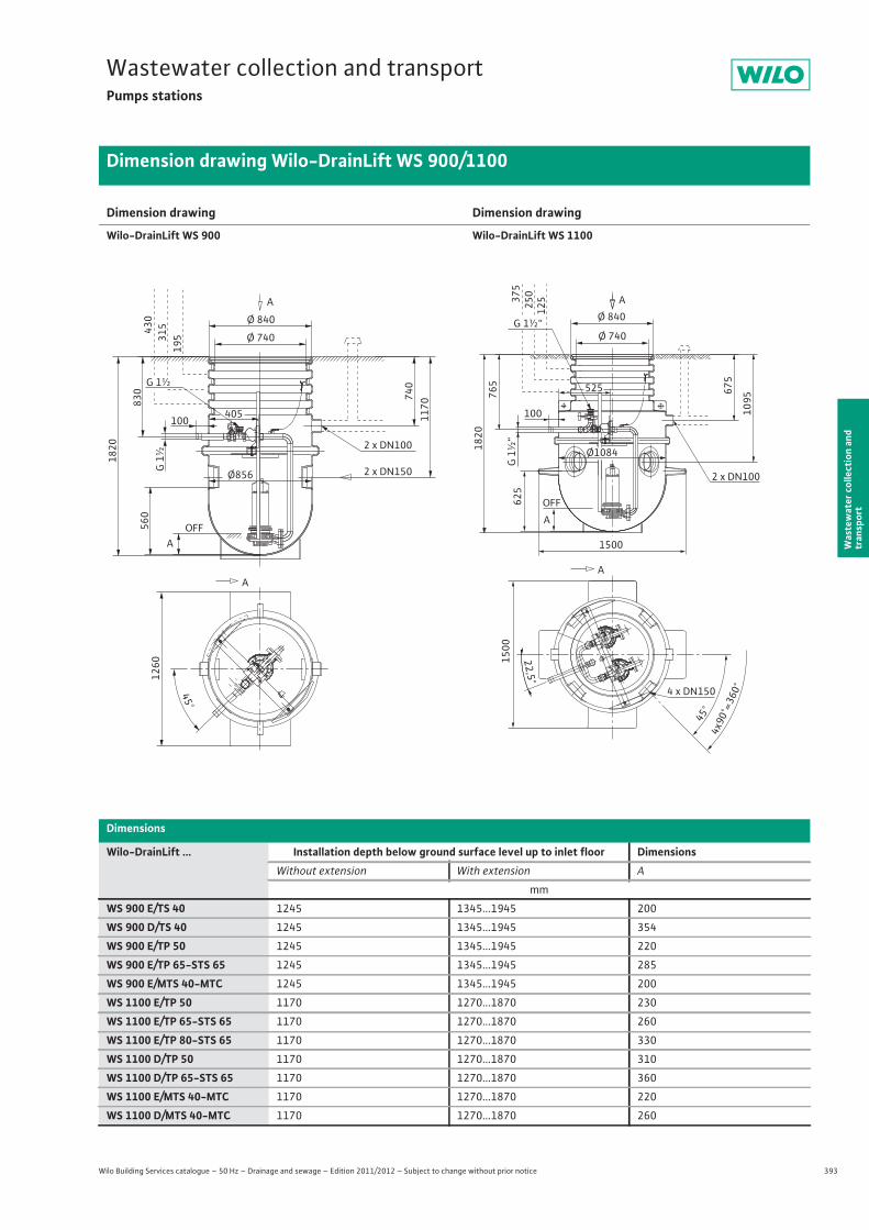
393
Wastewater collection and transportPumps stations
Wilo Building Services catalogue – 50 Hz – Drainage and sewage – Edition 2011/2012 – Subject to change without prior notice
Dimension drawing Wilo-DrainLift WS 900/1100
Was
tew
ater
col
lect
ion
and
tran
spor
t
Dimension drawing
Wilo-DrainLift WS 900
Dimension drawing
Wilo-DrainLift WS 1100
A
Ø 840
Ø 740
G 1½
G 1½
405100
OFF
830
Ø856
560
1820
740
1170
A
430
315
195
A
1260
45°
2 x DN150
2 x DN100
22,5°
45°
4x90
°=36
0°4 x DN150
1500
525
100
OFF
1500
2 x DN100
625
1820
765
1095
675
A37
525
012
5
Ø1084
G 1½“
G 1½
“
A
AØ 840
Ø 740
Dimensions
Wilo-DrainLift ... Installation depth below ground surface level up to inlet floor DimensionsWithout extension With extension A
mm
WS 900 E/TS 40 1245 1345...1945 200
WS 900 D/TS 40 1245 1345...1945 354
WS 900 E/TP 50 1245 1345...1945 220
WS 900 E/TP 65-STS 65 1245 1345...1945 285
WS 900 E/MTS 40-MTC 1245 1345...1945 200
WS 1100 E/TP 50 1170 1270...1870 230
WS 1100 E/TP 65-STS 65 1170 1270...1870 260
WS 1100 E/TP 80-STS 65 1170 1270...1870 330
WS 1100 D/TP 50 1170 1270...1870 310
WS 1100 D/TP 65-STS 65 1170 1270...1870 360
WS 1100 E/MTS 40-MTC 1170 1270...1870 220
WS 1100 D/MTS 40-MTC 1170 1270...1870 260
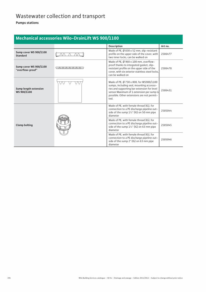
394 Wilo Building Services catalogue – 50 Hz – Drainage and sewage – Edition 2011/2012 – Subject to change without prior notice
Wastewater collection and transportPumps stations
Mechanical accessories Wilo-DrainLift WS 900/1100
Description Art no.
Sump cover WS 900/1100 Standard
Made of PE, Ø 830 x 52 mm, slip-resistant profile on the upper side of the cover, with two inner locks, can be walked on
2506477
Sump cover WS 900/1100 “overflow-proof”
Made of PE, Ø 960 x 100 mm, overflow-proof thanks to integrated gasket, slip-resistant profile on the upper side of the cover, with six exterior stainless steel locks, can be walked on
2506478
Sump length extension WS 900/1100
Made of PE, Ø 730 x 800, for WS900/1100 sumps, including seal, mounting accesso-ries and supporting bar extension for level sensor Maximum of 1 extension per sump is possible. Other extensions are not permit-ted.
2506431
Clamp bolting
Made of PE, with female thread (IG), for connection to a PE discharge pipeline out-side of the sump 1½" (IG) on 50 mm pipe diameter
2505044
Made of PE, with female thread (IG), for connection to a PE discharge pipeline out-side of the sump 1½" (IG) on 63 mm pipe diameter
2505045
Made of PE, with female thread (IG), for connection to a PE discharge pipeline out-side of the sump 2" (IG) on 63 mm pipe diameter
2505046
PLASSIM
395
Wastewater collection and transportPumps stations
Wilo Building Services catalogue – 50 Hz – Drainage and sewage – Edition 2011/2012 – Subject to change without prior notice
Mechanical accessories Wilo-DrainLift WS 900/1100
Was
tew
ater
col
lect
ion
and
tran
spor
t
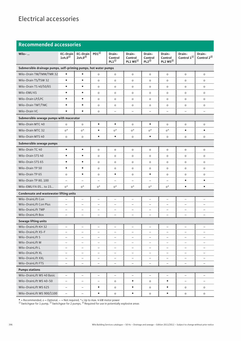
396 Wilo Building Services catalogue – 50 Hz – Drainage and sewage – Edition 2011/2012 – Subject to change without prior notice
Electrical accessories
Recommended accessories
Wilo- ... EC-Drain 1x4,01)
EC-Drain 2x4,02)
PD11) Drain-Control PL11)
Drain-Control PL1 WS1)
Drain-Control PL22)
Drain-Control PL2 WS2)
Drain-Control 11)
Drain-Control 22)
Submersible drainage pumps, self-priming pumps, hot water pumps
Wilo-Drain TM/TMW/TMR 32 • • o o o o o o o
Wilo-Drain TS/TSW 32 • • o o o o o o o
Wilo-Drain TS 40/50/65 • • o o o o o o o
Wilo-EMU KS • • o o o o o o o
Wilo-Drain LP/LPC • • o o o o o o o
Wilo-Drain TMT/TMC • • o o o o o o o
Wilo-Drain VC • • o – – – – – –
Submersible sewage pumps with macerator
Wilo-Drain MTC 40 o o • • o • o o o
Wilo-Drain MTC 32 o* o* • o* o* o* o* • •Wilo-Drain MTS 40 o o • • o • o o o
Submersible sewage pumps
Wilo-Drain TC 40 • • o o o o o o o
Wilo-Drain STS 40 • • o o o o o o o
Wilo-Drain STS 65 • • o o o o o o o
Wilo-Drain TP 50 • • o o o o o o o
Wilo-Drain TP 65 o • o • o • o o o
Wilo-Drain TP 80, 100 – – – – – – – • •Wilo-EMU FA 05... to 15... o* o* o* o* o* o* o* • •Condensate and wastewater lifting units
Wilo-DrainLift Con – – – – – – – – –
Wilo-DrainLift Con Plus – – – – – – – – –
Wilo-DrainLift TMP – – – – – – – – –
Wilo-DrainLift Box – – – – – – – – –
Sewage lifting units
Wilo-DrainLift KH 32 – – – – – – – – –
Wilo-DrainLift XS-F – – – – – – – – –
Wilo-DrainLift S – – – – – – – – –
Wilo-DrainLift M – – – – – – – – –
Wilo-DrainLift L – – – – – – – – –
Wilo-DrainLift XL – – – – – – – – –
Wilo-DrainLift XXL – – – – – – – – –
Wilo-DrainLift FTS – – – – – – – – –
Pumps stations
Wilo-DrainLift WS 40 Basic – – – – – – – – –
Wilo-DrainLift WS 40-50 – – – o • o • – –
Wilo-DrainLift WS 625 – – • o • o • o o
Wilo-DrainLift WS 900/1100 – – • o • o • o o
• = Recommended, o = Optional, – = Not required, *= Up to max. 4 kW motor power1) Switchgear for 1 pump, 2) Switchgear for 2 pumps, 3) Required for use in potentially explosive areas
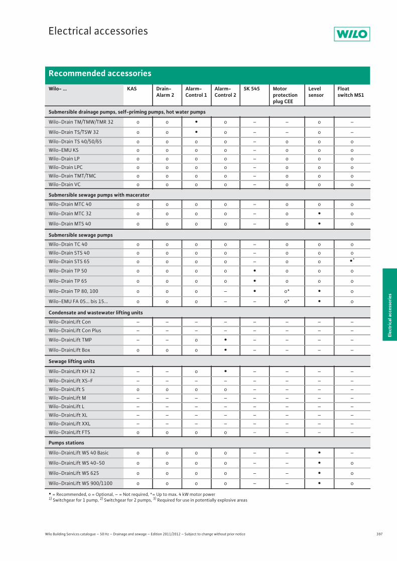
397
Electrical accessories
Wilo Building Services catalogue – 50 Hz – Drainage and sewage – Edition 2011/2012 – Subject to change without prior notice
Recommended accessories
Elec
tric
al a
cces
sorie
s
Wilo- ... KAS Drain-Alarm 2
Alarm-Control 1
Alarm-Control 2
SK 545 Motor protection plug CEE
Level sensor
Float switch MS1
Submersible drainage pumps, self-priming pumps, hot water pumps
Wilo-Drain TM/TMW/TMR 32 o o • o – – o –
Wilo-Drain TS/TSW 32 o o • o – – o –
Wilo-Drain TS 40/50/65 o o o o – o o o
Wilo-EMU KS o o o o – o o o
Wilo-Drain LP o o o o – o o o
Wilo-Drain LPC o o o o – o o o
Wilo-Drain TMT/TMC o o o o – o o o
Wilo-Drain VC o o o o – o o o
Submersible sewage pumps with macerator
Wilo-Drain MTC 40 o o o o – o o o
Wilo-Drain MTC 32 o o o o – o • o
Wilo-Drain MTS 40 o o o o – o • o
Submersible sewage pumps
Wilo-Drain TC 40 o o o o – o o o
Wilo-Drain STS 40 o o o o – o o o
Wilo-Drain STS 65 o o o o – o o •*
Wilo-Drain TP 50 o o o o • o o o
Wilo-Drain TP 65 o o o o • o o o
Wilo-Drain TP 80, 100 o o o – • o* • o
Wilo-EMU FA 05... bis 15... o o o – – o* • o
Condensate and wastewater lifting units
Wilo-DrainLift Con – – – – – – – –
Wilo-DrainLift Con Plus – – – – – – – –
Wilo-DrainLift TMP – – o • – – – –
Wilo-DrainLift Box o o o • – – – –
Sewage lifting units
Wilo-DrainLift KH 32 – – o • – – – –
Wilo-DrainLift XS-F – – – – – – – –
Wilo-DrainLift S o o o o – – – –
Wilo-DrainLift M – – – – – – – –
Wilo-DrainLift L – – – – – – – –
Wilo-DrainLift XL – – – – – – – –
Wilo-DrainLift XXL – – – – – – – –
Wilo-DrainLift FTS o o o o – – – –
Pumps stations
Wilo-DrainLift WS 40 Basic o o o o – – • –
Wilo-DrainLift WS 40-50 o o o o – – • o
Wilo-DrainLift WS 625 o o o o – – • o
Wilo-DrainLift WS 900/1100 o o o o – – • o
• = Recommended, o = Optional, – = Not required, *= Up to max. 4 kW motor power1) Switchgear for 1 pump, 2) Switchgear for 2 pumps, 3) Required for use in potentially explosive areas
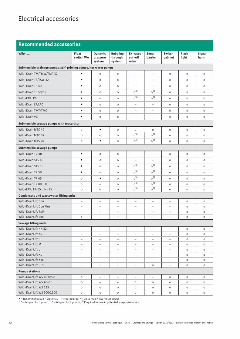
398 Wilo Building Services catalogue – 50 Hz – Drainage and sewage – Edition 2011/2012 – Subject to change without prior notice
Electrical accessories
Recommended accessories
Wilo- ... Floatswitch WA
Dynamic pressuresystem
Bubbling-throughsystem
Ex-rated cut-offrelay
Zenerbarrier
Switchcabinet
Flashlight
Signalhorn
Submersible drainage pumps, self-priming pumps, hot water pumps
Wilo-Drain TM/TMW/TMR 32 • o o – – o o o
Wilo-Drain TS/TSW 32 • o o – – o o o
Wilo-Drain TS 40 • o o – – o o o
Wilo-Drain TS 50/65 • o o o3) o3) o o o
Wilo-EMU KS • o o o3) o3) o o o
Wilo-Drain LP/LPC • o o – – o o o
Wilo-Drain TMT/TMC • o o – – o o o
Wilo-Drain VC • o o – – o o o
Submersible sewage pumps with macerator
Wilo-Drain MTC 40 o • o o o o o o
Wilo-Drain MTC 32 o o o o3) o3) o o o
Wilo-Drain MTS 40 o • o o3) o3) o o o
Submersible sewage pumps
Wilo-Drain TC 40 • o o – – o o o
Wilo-Drain STS 40 • o o – – o o o
Wilo-Drain STS 65 • o o o3) o3) o o o
Wilo-Drain TP 50 • o o o3) o3) o o o
Wilo-Drain TP 65 o • o o3) o3) o o o
Wilo-Drain TP 80, 100 o – o o3) o3) o o o
Wilo-EMU FA 05... bis 15... o o o o3) o3) o o o
Condensate and wastewater lifting units
Wilo-DrainLift Con – – – – – – o o
Wilo-DrainLift Con Plus – – – – – – o o
Wilo-DrainLift TMP – – – – – – o o
Wilo-DrainLift Box o – – – – – o o
Sewage lifting units
Wilo-DrainLift KH 32 – – – – – – o o
Wilo-DrainLift XS-F – – – – – – o o
Wilo-DrainLift S – – – – – – o o
Wilo-DrainLift M – – – – – – o o
Wilo-DrainLift L – – – – – – o o
Wilo-DrainLift XL – – – – – – o o
Wilo-DrainLift XXL – – – – – – o o
Wilo-DrainLift FTS – – – – o – o o
Pumps stations
Wilo-DrainLift WS 40 Basic o – – – – o o o
Wilo-DrainLift WS 40-50 o – – o o o o o
Wilo-DrainLift WS 625 o o o o o o o o
Wilo-DrainLift WS 900/1100 o o o o o o o o
• = Recommended, o = Optional, – = Not required, *= Up to max. 4 kW motor power1) Switchgear for 1 pump, 2) Switchgear for 2 pumps, 3) Required for use in potentially explosive areas
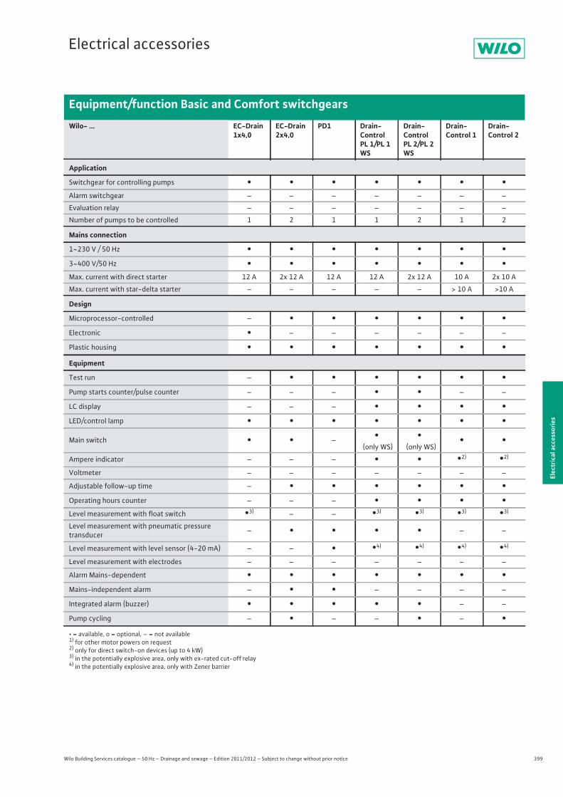
399
Electrical accessories
Wilo Building Services catalogue – 50 Hz – Drainage and sewage – Edition 2011/2012 – Subject to change without prior notice
Equipment/function Basic and Comfort switchgears
Elec
tric
al a
cces
sorie
s
Wilo- ... EC-Drain 1x4,0
EC-Drain 2x4,0
PD1 Drain-Control PL 1/PL 1 WS
Drain-Control PL 2/PL 2 WS
Drain-Control 1
Drain-Control 2
Application
Switchgear for controlling pumps • • • • • • •Alarm switchgear – – – – – – –
Evaluation relay – – – – – – –
Number of pumps to be controlled 1 2 1 1 2 1 2
Mains connection
1~230 V / 50 Hz • • • • • • •3~400 V/50 Hz • • • • • • •Max. current with direct starter 12 A 2x 12 A 12 A 12 A 2x 12 A 10 A 2x 10 A
Max. current with star-delta starter – – – – – > 10 A >10 A
Design
Microprocessor-controlled – • • • • • •Electronic • – – – – – –
Plastic housing • • • • • • •Equipment
Test run – • • • • • •Pump starts counter/pulse counter – – – • • – –
LC display – – – • • • •LED/control lamp • • • • • • •Main switch • • – •
(only WS)•
(only WS)• •
Ampere indicator – – – • • •2) •2)
Voltmeter – – – – – – –
Adjustable follow-up time – • • • • • •Operating hours counter – – – • • • •Level measurement with float switch •3) – – •3) •3) •3) •3)
Level measurement with pneumatic pressure transducer – • • • • – –
Level measurement with level sensor (4-20 mA) – – • •4) •4) •4) •4)
Level measurement with electrodes – – – – – – –
Alarm Mains-dependent • • • • • • •Mains-independent alarm – • • – – – –
Integrated alarm (buzzer) • • • • • – –
Pump cycling – • – – • – •• = available, o = optional, – = not available1) for other motor powers on request2) only for direct switch-on devices (up to 4 kW)3) in the potentially explosive area, only with ex-rated cut-off relay4) in the potentially explosive area, only with Zener barrier
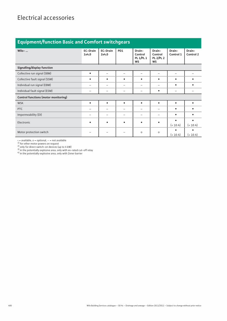
400 Wilo Building Services catalogue – 50 Hz – Drainage and sewage – Edition 2011/2012 – Subject to change without prior notice
Electrical accessories
Equipment/function Basic and Comfort switchgears
Signalling/display function
Collective run signal (SBM) • – – – – – –
Collective fault signal (SSM) • • • • • • •Individual run signal (EBM) – – – – – • •Individual fault signal (ESM) – – – – • – –
Control functions (motor monitoring)
WSK • • • • • • •PTC – – – – – • •Impermeability (DI) – – – – – • •Electronic • • • • • •
(< 10 A)•
(< 10 A)
Motor protection switch – – – o o •(< 10 A)
•(< 10 A)
Wilo- ... EC-Drain 1x4,0
EC-Drain 2x4,0
PD1 Drain-Control PL 1/PL 1 WS
Drain-Control PL 2/PL 2 WS
Drain-Control 1
Drain-Control 2
• = available, o = optional, – = not available1) for other motor powers on request2) only for direct switch-on devices (up to 4 kW)3) in the potentially explosive area, only with ex-rated cut-off relay4) in the potentially explosive area, only with Zener barrier
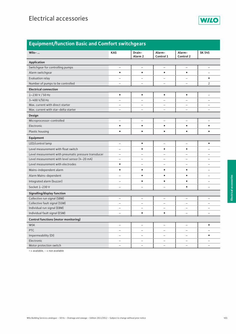
401
Electrical accessories
Wilo Building Services catalogue – 50 Hz – Drainage and sewage – Edition 2011/2012 – Subject to change without prior notice
Equipment/function Basic and Comfort switchgears
Elec
tric
al a
cces
sorie
s
• = available, - = not available
Wilo- ... KAS Drain-Alarm 2
Alarm-Control 1
Alarm-Control 2
SK 545
ApplicationSwitchgear for controlling pumps – – – – –
Alarm switchgear • • • • –
Evaluation relay – – – – •Number of pumps to be controlled – – – – 2
Electrical connection
1~230 V / 50 Hz • • • • –
3~400 V/50 Hz – – – – –Max. current with direct starter – – – – –Max. current with star-delta starter – – – – –
DesignMicroprocessor-controlled – – – – –
Electronic • • • • •Plastic housing • • • • •Equipment
LED/control lamp – • – – •Level measurement with float switch – • • • –
Level measurement with pneumatic pressure transducer – – – – –Level measurement with level sensor (4-20 mA) – – – – –
Level measurement with electrodes • – – – –
Mains-independent alarm • • • • –
Alarm Mains-dependent – • • • –
Integrated alarm (buzzer) – • • • –
Socket 1-230 V – – – • –
Signalling/display functionCollective run signal (SBM) – – – – –Collective fault signal (SSM) – – – – –Individual run signal (EBM) – – – – –
Individual fault signal (ESM) – • • – –
Control functions (motor monitoring)
WSK – – – – •PTC – – – – –
Impermeability (DI) – – – – •Electronic – – – – –Motor protection switch – – – – –
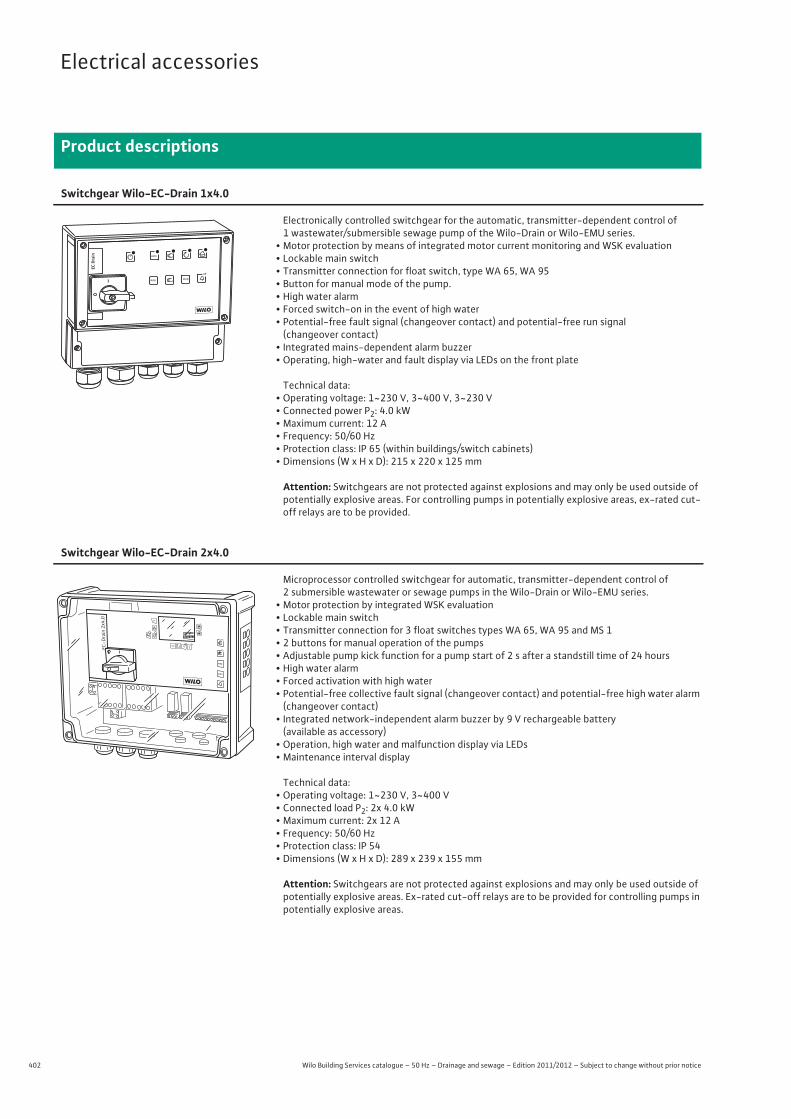
402 Wilo Building Services catalogue – 50 Hz – Drainage and sewage – Edition 2011/2012 – Subject to change without prior notice
Electrical accessories
Product descriptions
Switchgear Wilo-EC-Drain 1x4.0
Electronically controlled switchgear for the automatic, transmitter-dependent control of 1 wastewater/submersible sewage pump of the Wilo-Drain or Wilo-EMU series.
• Motor protection by means of integrated motor current monitoring and WSK evaluation• Lockable main switch• Transmitter connection for float switch, type WA 65, WA 95• Button for manual mode of the pump.• High water alarm• Forced switch-on in the event of high water• Potential-free fault signal (changeover contact) and potential-free run signal
(changeover contact)• Integrated mains-dependent alarm buzzer• Operating, high-water and fault display via LEDs on the front plate
Technical data:• Operating voltage: 1~230 V, 3~400 V, 3~230 V• Connected power P2: 4.0 kW• Maximum current: 12 A• Frequency: 50/60 Hz• Protection class: IP 65 (within buildings/switch cabinets)• Dimensions (W x H x D): 215 x 220 x 125 mm
Attention: Switchgears are not protected against explosions and may only be used outside of potentially explosive areas. For controlling pumps in potentially explosive areas, ex-rated cut-off relays are to be provided.
Switchgear Wilo-EC-Drain 2x4.0
Microprocessor controlled switchgear for automatic, transmitter-dependent control of 2 submersible wastewater or sewage pumps in the Wilo-Drain or Wilo-EMU series.
• Motor protection by integrated WSK evaluation• Lockable main switch• Transmitter connection for 3 float switches types WA 65, WA 95 and MS 1• 2 buttons for manual operation of the pumps• Adjustable pump kick function for a pump start of 2 s after a standstill time of 24 hours• High water alarm• Forced activation with high water• Potential-free collective fault signal (changeover contact) and potential-free high water alarm
(changeover contact)• Integrated network-independent alarm buzzer by 9 V rechargeable battery
(available as accessory)• Operation, high water and malfunction display via LEDs• Maintenance interval display
Technical data:• Operating voltage: 1~230 V, 3~400 V• Connected load P2: 2x 4.0 kW• Maximum current: 2x 12 A• Frequency: 50/60 Hz• Protection class: IP 54• Dimensions (W x H x D): 289 x 239 x 155 mm
Attention: Switchgears are not protected against explosions and may only be used outside of potentially explosive areas. Ex-rated cut-off relays are to be provided for controlling pumps in potentially explosive areas.
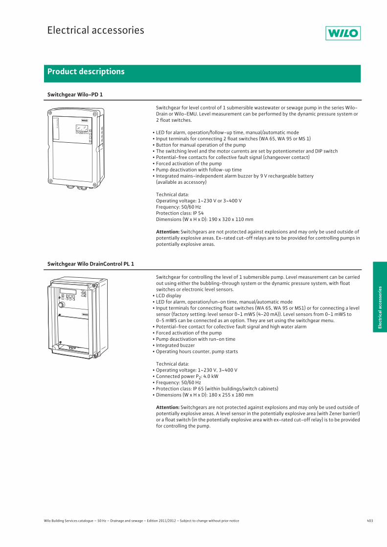
403
Electrical accessories
Wilo Building Services catalogue – 50 Hz – Drainage and sewage – Edition 2011/2012 – Subject to change without prior notice
Product descriptions
Elec
tric
al a
cces
sorie
s
Switchgear Wilo-PD 1
Switchgear for level control of 1 submersible wastewater or sewage pump in the series Wilo-Drain or Wilo-EMU. Level measurement can be performed by the dynamic pressure system or 2 float switches.
• LED for alarm, operation/follow-up time, manual/automatic mode• Input terminals for connecting 2 float switches (WA 65, WA 95 or MS 1)• Button for manual operation of the pump• The switching level and the motor currents are set by potentiometer and DIP switch• Potential-free contacts for collective fault signal (changeover contact)• Forced activation of the pump• Pump deactivation with follow-up time• Integrated mains-independent alarm buzzer by 9 V rechargeable battery
(available as accessory)
Technical data:Operating voltage: 1~230 V or 3~400 VFrequency: 50/60 HzProtection class: IP 54Dimensions (W x H x D): 190 x 320 x 110 mm
Attention: Switchgears are not protected against explosions and may only be used outside of potentially explosive areas. Ex-rated cut-off relays are to be provided for controlling pumps in potentially explosive areas.
Switchgear Wilo DrainControl PL 1
Switchgear for controlling the level of 1 submersible pump. Level measurement can be carried out using either the bubbling-through system or the dynamic pressure system, with float switches or electronic level sensors.
• LCD display• LED for alarm, operation/run-on time, manual/automatic mode• Input terminals for connecting float switches (WA 65, WA 95 or MS1) or for connecting a level
sensor (factory setting: level sensor 0-1 mWS (4-20 mA)). Level sensors from 0-1 mWS to 0-5 mWS can be connected as an option. They are set using the switchgear menu.
• Potential-free contact for collective fault signal and high water alarm• Forced activation of the pump• Pump deactivation with run-on time• Integrated buzzer• Operating hours counter, pump starts
Technical data:• Operating voltage: 1~230 V, 3~400 V• Connected power P2: 4.0 kW• Frequency: 50/60 Hz• Protection class: IP 65 (within buildings/switch cabinets)• Dimensions (W x H x D): 180 x 255 x 180 mm
Attention: Switchgears are not protected against explosions and may only be used outside of potentially explosive areas. A level sensor in the potentially explosive area (with Zener barrier!) or a float switch (in the potentially explosive area with ex-rated cut-off relay) is to be provided for controlling the pump.
autooff rreseseett
auto
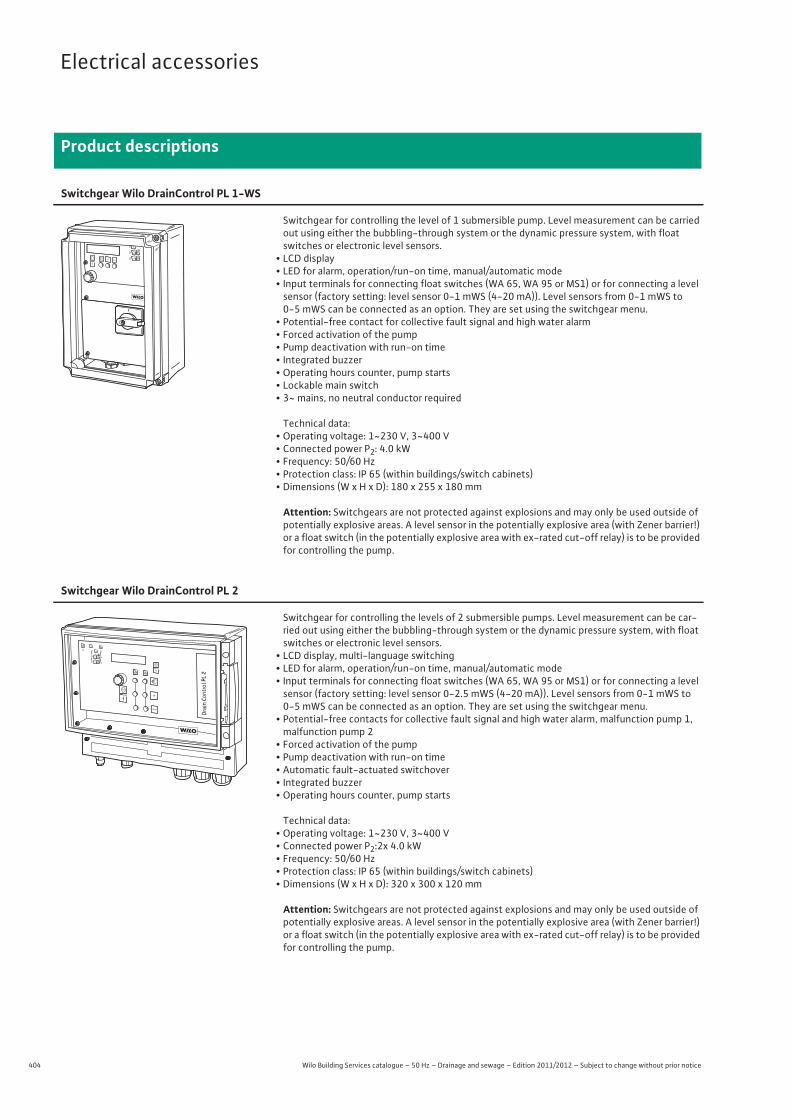
404 Wilo Building Services catalogue – 50 Hz – Drainage and sewage – Edition 2011/2012 – Subject to change without prior notice
Electrical accessories
Product descriptions
Switchgear Wilo DrainControl PL 1-WS
Switchgear for controlling the level of 1 submersible pump. Level measurement can be carried out using either the bubbling-through system or the dynamic pressure system, with float switches or electronic level sensors.
• LCD display• LED for alarm, operation/run-on time, manual/automatic mode• Input terminals for connecting float switches (WA 65, WA 95 or MS1) or for connecting a level
sensor (factory setting: level sensor 0-1 mWS (4-20 mA)). Level sensors from 0-1 mWS to 0-5 mWS can be connected as an option. They are set using the switchgear menu.
• Potential-free contact for collective fault signal and high water alarm• Forced activation of the pump• Pump deactivation with run-on time• Integrated buzzer• Operating hours counter, pump starts• Lockable main switch• 3~ mains, no neutral conductor required
Technical data:• Operating voltage: 1~230 V, 3~400 V• Connected power P2: 4.0 kW• Frequency: 50/60 Hz• Protection class: IP 65 (within buildings/switch cabinets)• Dimensions (W x H x D): 180 x 255 x 180 mm
Attention: Switchgears are not protected against explosions and may only be used outside of potentially explosive areas. A level sensor in the potentially explosive area (with Zener barrier!) or a float switch (in the potentially explosive area with ex-rated cut-off relay) is to be provided for controlling the pump.
autooff rreseseett
auto
Switchgear Wilo DrainControl PL 2
Switchgear for controlling the levels of 2 submersible pumps. Level measurement can be car-ried out using either the bubbling-through system or the dynamic pressure system, with float switches or electronic level sensors.
• LCD display, multi-language switching• LED for alarm, operation/run-on time, manual/automatic mode• Input terminals for connecting float switches (WA 65, WA 95 or MS1) or for connecting a level
sensor (factory setting: level sensor 0-2.5 mWS (4-20 mA)). Level sensors from 0-1 mWS to 0-5 mWS can be connected as an option. They are set using the switchgear menu.
• Potential-free contacts for collective fault signal and high water alarm, malfunction pump 1, malfunction pump 2
• Forced activation of the pump• Pump deactivation with run-on time• Automatic fault-actuated switchover• Integrated buzzer• Operating hours counter, pump starts
Technical data:• Operating voltage: 1~230 V, 3~400 V• Connected power P2:2x 4.0 kW• Frequency: 50/60 Hz• Protection class: IP 65 (within buildings/switch cabinets)• Dimensions (W x H x D): 320 x 300 x 120 mm
Attention: Switchgears are not protected against explosions and may only be used outside of potentially explosive areas. A level sensor in the potentially explosive area (with Zener barrier!) or a float switch (in the potentially explosive area with ex-rated cut-off relay) is to be provided for controlling the pump.
auto
off
resetP2
reset
auto
reset
P1
P2P1
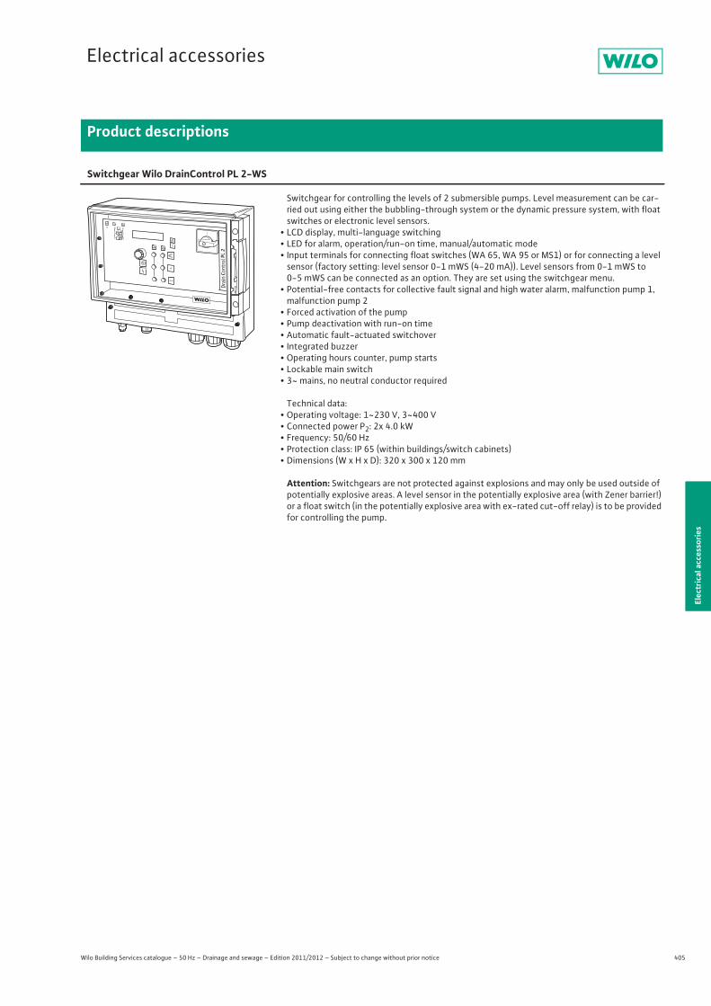
405
Electrical accessories
Wilo Building Services catalogue – 50 Hz – Drainage and sewage – Edition 2011/2012 – Subject to change without prior notice
Product descriptions
Elec
tric
al a
cces
sorie
s
Switchgear Wilo DrainControl PL 2-WS
Switchgear for controlling the levels of 2 submersible pumps. Level measurement can be car-ried out using either the bubbling-through system or the dynamic pressure system, with float switches or electronic level sensors.
• LCD display, multi-language switching• LED for alarm, operation/run-on time, manual/automatic mode• Input terminals for connecting float switches (WA 65, WA 95 or MS1) or for connecting a level
sensor (factory setting: level sensor 0-1 mWS (4-20 mA)). Level sensors from 0-1 mWS to 0-5 mWS can be connected as an option. They are set using the switchgear menu.
• Potential-free contacts for collective fault signal and high water alarm, malfunction pump 1, malfunction pump 2
• Forced activation of the pump• Pump deactivation with run-on time• Automatic fault-actuated switchover• Integrated buzzer• Operating hours counter, pump starts• Lockable main switch• 3~ mains, no neutral conductor required
Technical data:• Operating voltage: 1~230 V, 3~400 V• Connected power P2: 2x 4.0 kW• Frequency: 50/60 Hz• Protection class: IP 65 (within buildings/switch cabinets)• Dimensions (W x H x D): 320 x 300 x 120 mm
Attention: Switchgears are not protected against explosions and may only be used outside of potentially explosive areas. A level sensor in the potentially explosive area (with Zener barrier!) or a float switch (in the potentially explosive area with ex-rated cut-off relay) is to be provided for controlling the pump.
auto
off
resetP2
reset
auto
reset
P1
P2P1
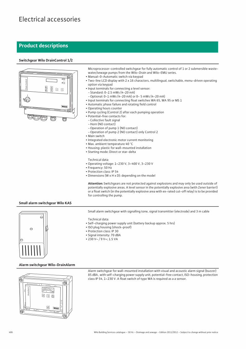
406 Wilo Building Services catalogue – 50 Hz – Drainage and sewage – Edition 2011/2012 – Subject to change without prior notice
Electrical accessories
Product descriptions
Switchgear Wilo DrainControl 1/2
Microprocessor-controlled switchgear for fully automatic control of 1 or 2 submersible waste-water/sewage pumps from the Wilo-Drain and Wilo-EMU series.
• Manual-0-Automatic switch via keypad• Two-line LCD display with 2 x 16 characters, multilingual, switchable, menu-driven operating
option via keypad• Input terminals for connecting a level sensor:
- Standard: 0-2.5 mWs (4-20 mA)- Optional: 0-1 mWs (4-20 mA) or 0- 5 mWs (4-20 mA)
• Input terminals for connecting float switches WA 65, WA 95 or MS 1• Automatic phase failure and rotating field control• Operating hours counter• Pump cycling (Control 2) after each pumping operation• Potential-free contacts for:
- Collective fault signal- Horn (NO contact)- Operation of pump 1 (NO contact)- Operation of pump 2 (NO contact) only Control 2
• Main switch• Integrated electronic motor current monitoring• Max. ambient temperature 40 °C• Housing: plastic for wall-mounted installation• Starting mode: Direct or star-delta
Technical data:• Operating voltage: 1~230 V, 3~400 V, 3~230 V• Frequency: 50 Hz• Protection class: IP 54• Dimensions (W x H x D): depending on the model
Attention: Switchgears are not protected against explosions and may only be used outside of potentially explosive areas. A level sensor in the potentially explosive area (with Zener barrier!) or a float switch (in the potentially explosive area with ex-rated cut-off relay) is to be provided for controlling the pump.
Small alarm switchgear Wilo KAS
Small alarm switchgear with signalling tone, signal transmitter (electrode) and 3 m cable
Technical data:• Self-charging power supply unit (battery backup approx. 5 hrs)• ISO plug housing (shock-proof)• Protection class: IP 30• Signal intensity: 70 dBA• 230 V~ / 9 V=; 1.5 VA
Alarm switchgear Wilo-DrainAlarm Alarm switchgear for wall-mounted installation with visual and acoustic alarm signal (buzzer)
85 dBA , with self-charging power supply unit, potential-free contact, ISO-housing, protection class IP 54, 1~230 V. A float switch of type WA is required as a a sensor.
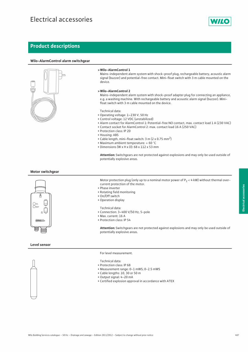
407
Electrical accessories
Wilo Building Services catalogue – 50 Hz – Drainage and sewage – Edition 2011/2012 – Subject to change without prior notice
Product descriptions
Elec
tric
al a
cces
sorie
s
Wilo-AlarmControl alarm switchgear
>Wilo-AlarmControl 1Mains-independent alarm system with shock-proof plug, rechargeable battery, acoustic alarm signal (buzzer) and potential-free contact. Mini-float switch with 3 m cable mounted on the device.
>Wilo-AlarmControl 2Mains-independent alarm system with shock-proof adapter plug for connecting an appliance, e.g. a washing machine. With rechargeable battery and acoustic alarm signal (buzzer). Mini-float switch with 3 m cable mounted on the device.
Technical data:• Operating voltage: 1~230 V, 50 Hz• Control voltage: 12 VDC (unstabilized)• Alarm contact for AlarmControl 1: Potential-free NO contact, max. contact load 1 A (230 VAC)• Contact socket for AlarmControl 2: max. contact load 16 A (250 VAC)• Protection class: IP 20• Housing: ABS• Cable length, mini-float switch: 3 m (2 x 0.75 mm2)• Maximum ambient temperature: + 60 °C• Dimensions (W x H x D): 68 x 112 x 53 mm
Attention: Switchgears are not protected against explosions and may only be used outside of potentially explosive areas.
Motor switchgear
Motor protection plug (only up to a nominal motor power of P2 < 4 kW) without thermal over-current protection of the motor.
• Phase inverter• Rotating field monitoring• On/Off switch• Operation display
Technical data:• Connection: 3~400 V/50 Hz, 5-pole• Max. current: 16 A• Protection class: IP 54
Attention: Switchgears are not protected against explosions and may only be used outside of potentially explosive areas.
Level sensor
For level measurement.
Technical data:• Protection class: IP 68• Measurement range: 0-1 mWS; 0-2.5 mWS• Cable lengths: 10, 30 or 50 m• Output signal: 4-20 mA• Certified explosion approval in accordance with ATEX
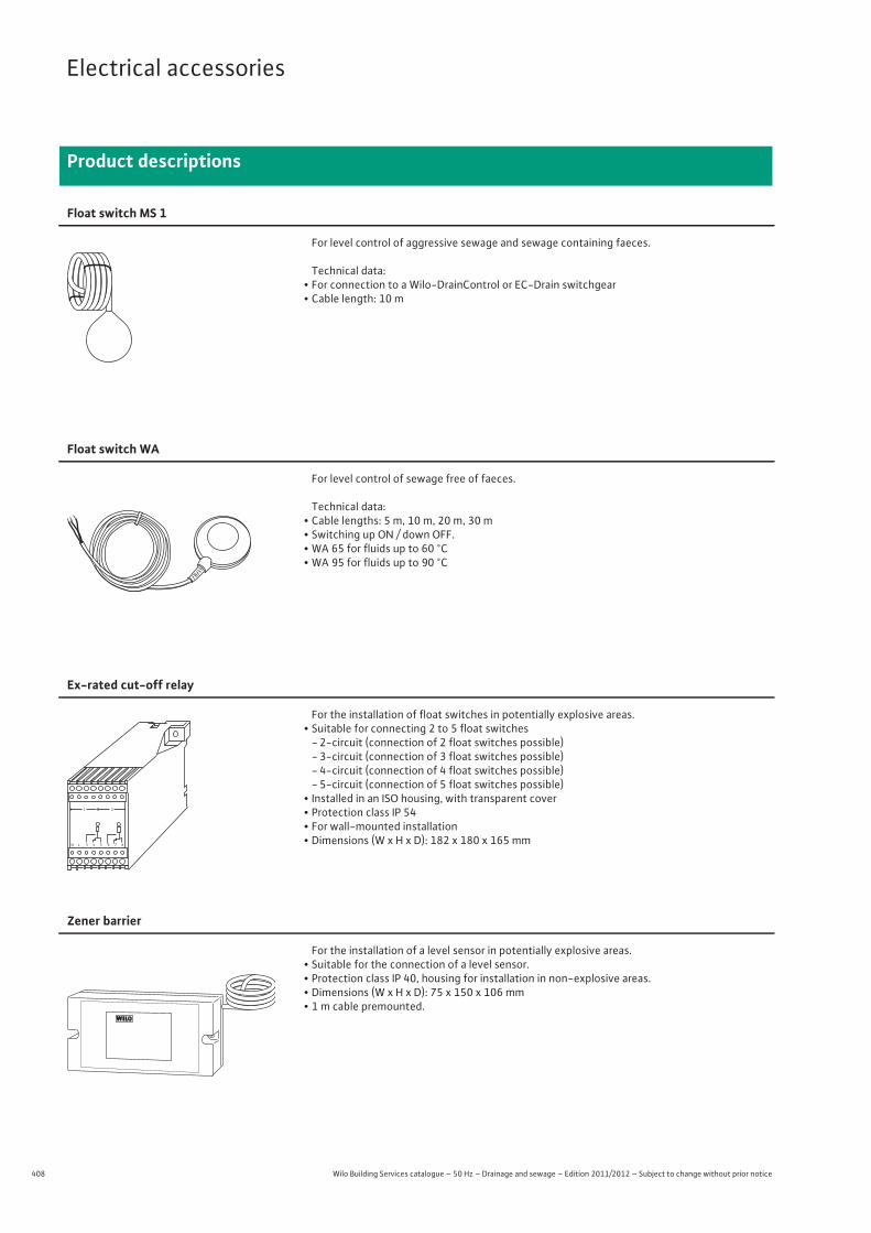
408 Wilo Building Services catalogue – 50 Hz – Drainage and sewage – Edition 2011/2012 – Subject to change without prior notice
Electrical accessories
Product descriptions
Float switch MS 1
For level control of aggressive sewage and sewage containing faeces.
Technical data:• For connection to a Wilo-DrainControl or EC-Drain switchgear• Cable length: 10 m
Float switch WA
For level control of sewage free of faeces.
Technical data:• Cable lengths: 5 m, 10 m, 20 m, 30 m• Switching up ON / down OFF.• WA 65 for fluids up to 60 °C• WA 95 for fluids up to 90 °C
Ex-rated cut-off relay
For the installation of float switches in potentially explosive areas.• Suitable for connecting 2 to 5 float switches
-2-circuit (connection of 2 float switches possible)-3-circuit (connection of 3 float switches possible)- 4-circuit (connection of 4 float switches possible)-5-circuit (connection of 5 float switches possible)
• Installed in an ISO housing, with transparent cover• Protection class IP 54• For wall-mounted installation• Dimensions (W x H x D): 182 x 180 x 165 mm
Zener barrier
For the installation of a level sensor in potentially explosive areas.• Suitable for the connection of a level sensor.• Protection class IP 40, housing for installation in non-explosive areas.• Dimensions (W x H x D): 75 x 150 x 106 mm• 1 m cable premounted.
1 2
N L 3 4 5 6 7 8
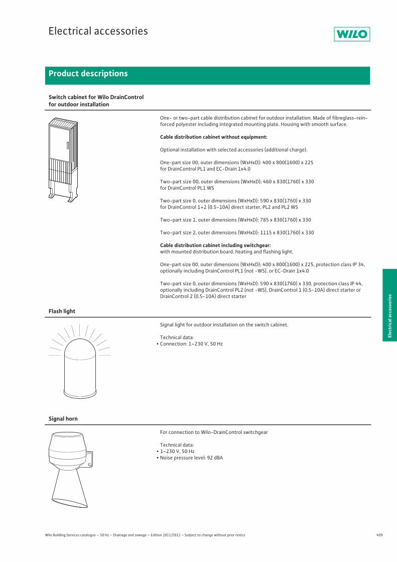
409
Electrical accessories
Wilo Building Services catalogue – 50 Hz – Drainage and sewage – Edition 2011/2012 – Subject to change without prior notice
Product descriptions
Elec
tric
al a
cces
sorie
s
Switch cabinet for Wilo DrainControl for outdoor installation
One- or two-part cable distribution cabinet for outdoor installation. Made of fibreglass-rein-forced polyester including integrated mounting plate. Housing with smooth surface.
Cable distribution cabinet without equipment:
Optional installation with selected accessories (additional charge).
One-part size 00, outer dimensions (WxHxD): 400 x 800(1600) x 225for DrainControl PL1 and EC-Drain 1x4.0
Two-part size 00, outer dimensions (WxHxD): 460 x 830(1760) x 330for DrainControl PL1 WS
Two-part size 0, outer dimensions (WxHxD): 590 x 830(1760) x 330for DrainControl 1+2 (0.5-10A) direct starter, PL2 and PL2 WS
Two-part size 1, outer dimensions (WxHxD): 785 x 830(1760) x 330
Two-part size 2, outer dimensions (WxHxD): 1115 x 830(1760) x 330
Cable distribution cabinet including switchgear:with mounted distribution board, heating and flashing light.
One-part size 00, outer dimensions (WxHxD): 400 x 800(1600) x 225, protection class IP 34,optionally including DrainControl PL1 (not -WS), or EC-Drain 1x4.0
Two-part size 0, outer dimensions (WxHxD): 590 x 830(1760) x 330, protection class IP 44,optionally including DrainControl PL2 (not -WS), DrainControl 1 (0.5-10A) direct starter or DrainControl 2 (0.5-10A) direct starter
Flash light
Signal light for outdoor installation on the switch cabinet.
Technical data:• Connection: 1~230 V, 50 Hz
Signal horn
For connection to Wilo-DrainControl switchgear
Technical data:• 1~230 V, 50 Hz• Noise pressure level: 92 dBA
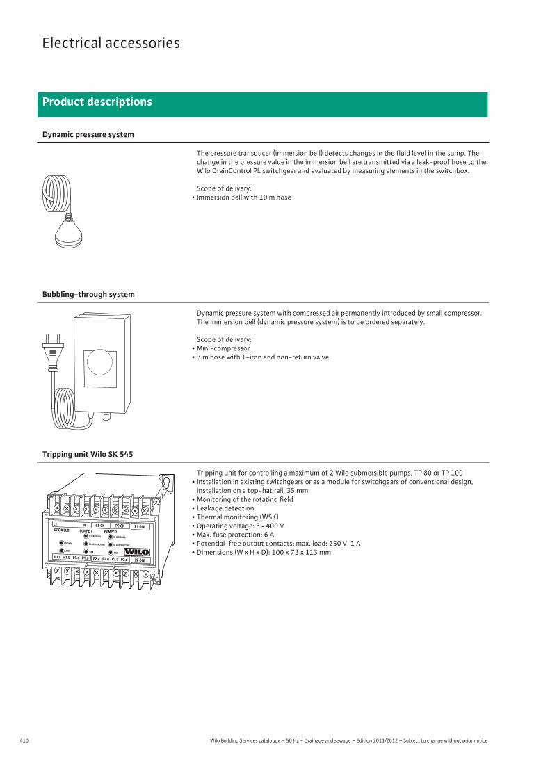
410 Wilo Building Services catalogue – 50 Hz – Drainage and sewage – Edition 2011/2012 – Subject to change without prior notice
Electrical accessories
Product descriptions
Dynamic pressure system
The pressure transducer (immersion bell) detects changes in the fluid level in the sump. The change in the pressure value in the immersion bell are transmitted via a leak-proof hose to the Wilo DrainControl PL switchgear and evaluated by measuring elements in the switchbox.
Scope of delivery:• Immersion bell with 10 m hose
Bubbling-through system
Dynamic pressure system with compressed air permanently introduced by small compressor. The immersion bell (dynamic pressure system) is to be ordered separately.
Scope of delivery:• Mini-compressor• 3 m hose with T-iron and non-return valve
Tripping unit Wilo SK 545
Tripping unit for controlling a maximum of 2 Wilo submersible pumps, TP 80 or TP 100• Installation in existing switchgears or as a module for switchgears of conventional design,
installation on a top-hat rail, 35 mm• Monitoring of the rotating field• Leakage detection• Thermal monitoring (WSK)• Operating voltage: 3~ 400 V• Max. fuse protection: 6 A• Potential-free output contacts; max. load: 250 V, 1 A• Dimensions (W x H x D): 100 x 72 x 113 mm
<��?���B?���B���?��?�?���W����W ��Y�B
���B?���?�\?��B��?�B�?B��W���������� ��������������� �������������� ��������������������� � �������������� ���������� ��
�\
��������������#$�'?�@�'��\��^_��`�{|}��|}�|�����������^�����������\��#���'
��������}��^'^���`�{����}��������_��#��_\#���
�� �����������������}������'��^�#�`�{��������}��}��^\��#����^��#�_�� �_\#���
��������}���`�_\_�_`�{�����|�������_��#��_\#��^
��������}������#��^`�{����|��}||�����\^'_���#��^��_��_\#��#����
�������������^�_�#`�{�|���������|��'#�^'�#���\^��$^\���_\#��#����
�������|�}|� �_�_��$`�{��� ||�||���}�^'�_$����$'^����_\#���
������������¡\��������'`�{����}}��}�����_\#����_��^����
������ ������|��@$�����^`�{��|����|�}|���_��#��_\#���
������ ���������¢�������`�{����}|��������^'_���^'�_£^���_\#¤���_��#
��!��� ��}���}�� �̀���^��`�{�����}�}|�����_��#��_\#�$�
��'���|�}}
"����#�$����������¥�$��_�_�'_^�¦
"����#�$����������¥§^�'^�^����_#��#��_�^�¦
�������¨©ª«��¢ª��«¬�¢'�^��_�� ��¢�� }|��¢�©� _$���¢$��#����^��$^�#��¢_'^�`{����}}����}���|�_��#���\��#���#���'�� ����¨©ª«�®$��^�¯��^''^_�� ´��µ|��}�¨_^�^'�¬^$�#'�`�{����������¤�#��_�^��_\#�������!�����¨©ª«� ���_���ªª }�}�����$`�{����}|����|��|_��#��_\#��������� ¨©ª«��^\�«««||������_���`�{����}��|�������_\#��_\#��£������¨©ª«��¢¶¬·}����´����#'^�`�{�|�|���|����_��#��_\#��^��������¨©ª«��$\��'_��ª���}}|���#�_��`�{����|����}���_��#��_\#���%����¨©ª«� ������©���� �\��'£?�¢\�^'���`|¢��ª�`�{}�����|�������_\\�\#�^��_\#¤����#�%&��¨©ª«� �_���ª���}�}�����^_�_��`�{���}������}����_\#����_\#��#����
%������¨©ª«�µ'���������#�#��}�����¸��'^�`�{����}������}��_\#¤�'��������_\#��'
%���&�����!���¨©ª«�®'������'�#�|�}�}� ^��\_�^`�{�|��|�������}}_��#��_\#���
'����¨©ª«�@����'��¢¶�|����¹�'\�\$��^`�{������|���}|�_\#��_\#���
( ����¨©ª«��^��_�«º}|�}�� �̀\\_��`�{��|���������_��#��_\#�^^
)����¨©ª«�»_�\����«��|�������##`�{����|����}����_\#��_\#��_
)����¨©ª«���¢����������#_���¾¢'�£`�{���}���������_��#��_\#��'
������������¨©ª«�¥¡�¹�¦�ª���@�}��|¨¿��$'�#�¤¡�#�¤`'^��`�{���}|����|������\^���_\#��#�$�
������¨©ª«�µ^\\���¢´}�����¢�_�_�¥¢��_��¦`�{��|�}���|������_\#�_��#��_\#��'
�����*¨©ª«����£�'#'��À��¹��|����`Á'Á��À\_��¥�$���^��¦`�{���|���������_\#��_\#��$
$���¨©ª«�©��_������^'����®\����®$����ª���®$�^��}}�}�`�{�}�|��|���|}���^'�_�^��$������^'�\�����#�_�
$��� ��¨©ª«�®$����©��#�^�_�¿���'����^\�����}|}��`�{�|�|}��|������_�'��_\#������^��_�
$�����¨©ª«����_�^^'_���ª���ª_�^'_��`�{�����}�||������\^���_\#�_^
$���*¨©ª«�©��\_����'�\�|�����®^���_^'��#''#�^#��¥�_\��#¦`�{���|������}�_\#�_��\_���_\#�_�
+����& ��¨©ª«� ^��'�\�¢�_�������|�¢\���£`�{���|��|�����}_��#��_\#���
+����¨©ª«�®$����ª�����|}¤����´_���^´£^#�����`�{�|������������_\#��_\#��#��'
,�����¨©ª«���\�_���©¢}�}��§_��`�{��}���}��||���_\��_\#�\�
,�!��¨©ª«��¢ª��«¬�ª^���#�}|�||�����\��^��`�{��}����|||����\��£�^'_���^��\�,��&����¨©ª«�ª_^�$���¡¢���|�|�·_\�_$�`�{������|}�������_\��_\#�\���&��-��&����� ¨©ª«�¬^�^'\��������}��}�¬¢�¨^������`�{�}������������_��#��_\#��\-��.�*¨©ª«�¬#'�^�¢������«�\#`�{���||��������_\#��_\#��#/����¨©ª«�®#\����������#�#���¤����§���£�`�{���||���|�}�}�_\#��_\#��\/��������#�����¨_\#¤��\��#�®#'�$��\�ª�������¤����®#'�#`�{��}�||�|�������#������_\#��������¨©ª«�§#���_����'�\�������� #��� �_����¿$���©\�#�`�{���|}��}��}���_\#��_\#�'#
�� ��¨©ª«�§$��###}|���|��#��#�`�{��������}�����_\#��_\#�'$
0��������!��¨©ª«����¤�§_£���§_£����}}���`�{����}���|�������#$\�������_�_����#�
0��!��������������¨©ª«��^#�'�����#�#�}}�����^#�'��`�{��}�}}�|��}|��#��_�^��_\#��#�£$
0�������¨©ª«��\#���_����'�#���}����'��_�\���`�{�|}�|����}��}}�_\#��_\#���
0������¨©ª«�¢�'_��_����#�#�}����ª�$�\����`�{����}�����}���_\#���'_��_���_\#��_
0���&��2������\��#���#$���¢�'_��}�}����^���\^`�{|��}}����|���^''#\��#'�^\_$����\��#���#���
0���¨©ª«�©�Â'_�����¢�|�����¢\��\À��^�µ^��'^�¥���'_�¦`�{����}�����}���_\#�_�^'_����_\#�^�
0.���¨©ª«���^'_�^�¢���|���·Ã��Á`�{��������|�����_\#��_\#��^
0.������������®$��^��¢´��}��§�^_��^\�^�`�{�}��}������¤|�_��#�^��¤�$��^����
���.�©̈ª«¤��¡�̀ �_���� #��ª���
}}�� �̀_�^�`�{����||����}����^\�#���$��_\#^�$��_�����#����
�����*¨©ª«�®#�����_��^�\^'_�������^�`_���¢��Ä�������©�����$\`�{���|}����}�|}}�_\#��_\#��#���'
������¨©ª«�¡�'�_�����#����}����¹_^�`�{�������|�}}����_\#��_\#�$�
���������!�(����� ¨©ª«��_��\^������»¸�¿^�^\�¢\_�»'^^�¸#�^�¤�#$���¤�@$��_`�{��}��������}���_��#��_\#��^
�0�¨©ª«�¡�¢�ªª �}|���¬�|��� ¢�^�^\'#�^�®�'�?�©\\_�#_����}��`�{}������������|_��#��_\#¤$����#�
3����¨©ª«�·_^����� #�ª���µ#� �_��_��� _�£?�·_^����`�{�������}��������_����_\#���
¨©ª«����¬#'��_'��^���'�Å^�}����|���@#'��$��´^'���£`�{���|�}��}�|¤�»�{���|�}��}�|¤�����_\#��_\#��#������_\#��#�
Subject to change without prior notice. In appliance of our General Terms of Delivery and Service (see www.wilo.com)
2118888/1103/INT/MP
Recommended