Door ListID
D26Height
2,100Width
2,410Quantity1
OrientationR
From Room
A3A3A3A3A3A3A3A3A3A3A3A3A3A3A3A3A3A3A3A3A3A3A4
BASEMENT AREA CALCULATION DIARAMBASEMENT PLANCOVER PAGE & MATERIALS FINISHES SCHEDULEDEMOLITION PLANDRAFT LANDSCAPING PLANELEVATIONSELEVATIONSELEVATIONSFENCE ELEVATION & DETAILSFIRST FLOOR AREA CALCULATION DIAGRAMFIRST FLOOR PLANGROUND FLOOR AREA CALCULATION DIAGRAMGROUND FLOOR PLANIMPERVIOUS AREA CALCULATION DIAGRAMLANDSCAPING AREA CALCULATION DIAGRAMROOF PLANSECTION A-A & B-BSHADOW DIAGRAM ON JUNE 22NDSITE ANALYSIS PLAN AND PRIVACY PLANSITE MANAGEMENT/SEDIMENT CONTROL PLANSITE PLANSTREETSCAPE ELEVATIONNOTIFICATION PLAN
Window ListID Height
700Width
2,410Quantity1
OrientationR
From RoomD42W1W2W3W4W5W6W7W8W9W10W11W14W15W16W18W19W20W21W22W23W24W25W27W28W29W30W31W32W33W34W35W36W37W38W39W40W41W43W44W45W46W47W48W49W50W51W52
2,1002,4002,4002,4002,4008108105101,5006101,8102,1002,4002,4002,4002,4002,4002,4002,4003,0102,5592,1002,1002,1002,1002,1002,1001,0774501,2007107101,2001,2001,8491,2002,1002,1002,1007102,1002,1002,1002,1002,1702,1702,1002,100
9001,4501,4501,4501,4503,2008102,3538103,2002,1102,4008001,0542,2001,0001,0001,0001,0004,2402,7701,3501,3501,3501,3509009002,8103,2103,0007107103,0007105007109009009001,4109009009009004,2401,518900900
111111111111111111111111111111111111111111111111
LLRRLLLLLLRLLRLLRLLRRLLLLRRLLRLLLLLLLLRLRRRRLRRL
D26z
2,1002,100
2,410700
11
RR
D12D13D17D42
2,4102,4102,4102,100
4,1733,3843,690900
1111
LLLL
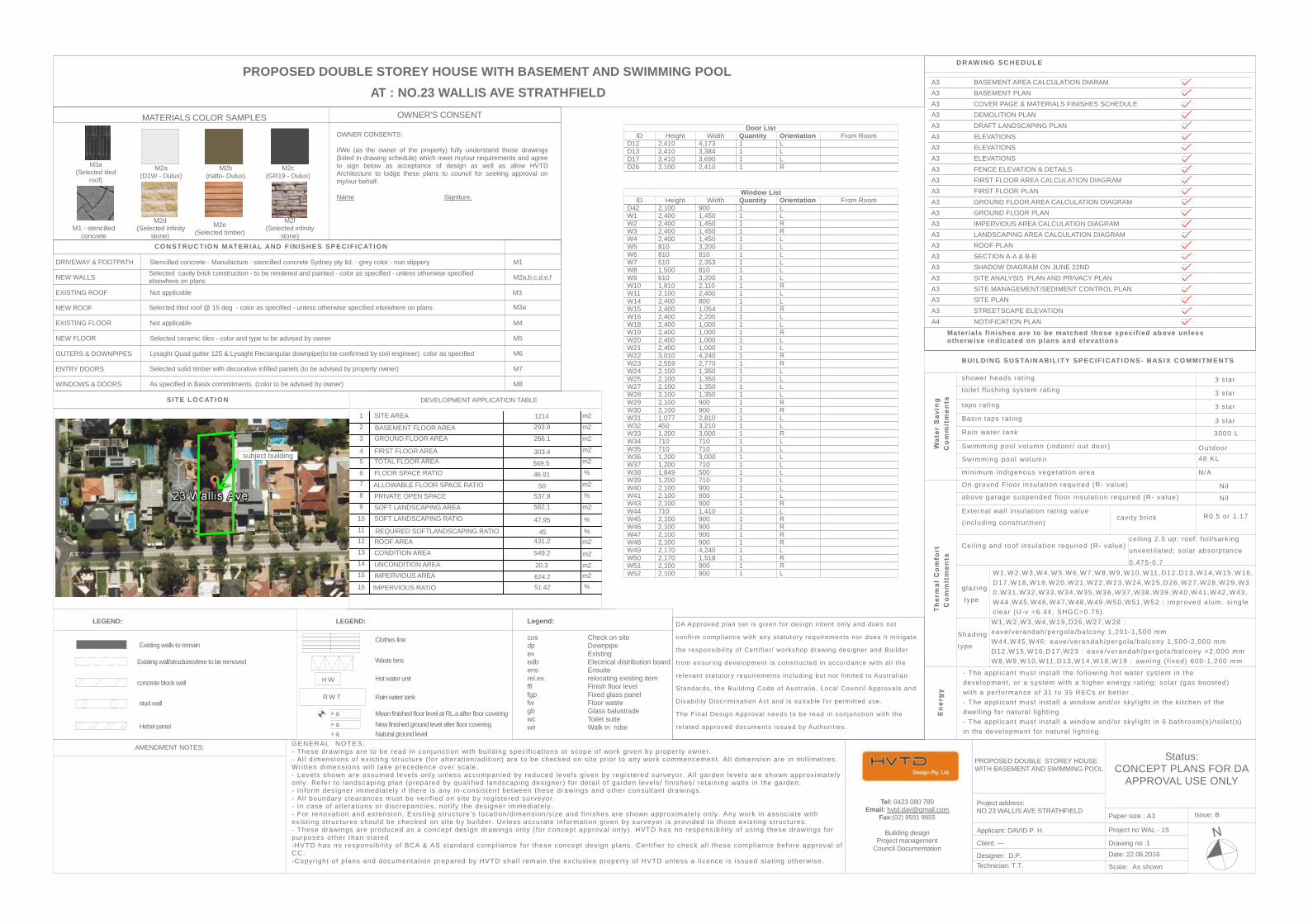
PROPOSED DOUBLE STOREY HOUSE WITH BASEMENT AND SWIMMING POOL
stud wall
concrete block wall
Existing walls to remain
Existing wall/structures/tree to be removed
Hebel panel
DEVELOPMENT APPLICATION TABLE
BUILDING SUSTAIN ABIL ITY SPECIF ICATION S- BASIX CO MMITM EN TS
Legend:
cos Check on site dp Downpipe ex Existing edb Electrical distribution board ens Ensuite rel.ex. relocating existing item ffl Finish floor level fgp Fixed glass panel fw Floor waste gb Glass balustrade wc Toilet suite wir Walk in robe
LEGEND:
shower heads rat ing
toi let f lushing system rat ing
taps rat ing
Basin taps rat ing
Rain water tank
Swimming pool vo lumn ( indoor/ out door )
Swimming pool wolumn
minimum ind igenous vegetat ion area
On ground Floor insulat ion required (R- value)
above garage suspended f loor insulat ion required (R- value)
External wal l insulat ion rat ing value
(including construct ion)
Ceil ing and roof insulat ion required (R- value)
glaz ing
type
Shading
type
D R AW IN G SC H ED U L E
LEGEND:
AT : NO.23 WALLIS AVE STRATHFIELD
Materials f inishes are to be matched those speci f ied above unlessotherw ise indicated on plans and elevations
OWNER CONSENTS:
I/We (as the owner of the property) fully understand these drawings(listed in drawing schedule) which meet my/our requirements and agreeto sign below as acceptance of design as well as allow HVTDArchitecture to lodge these plans to council for seeking approval onmy/our behalf.
Name Signiture.
SITE LO CATION
OWNER'S CONSENT
CON STR UC TIO N MATER IAL AND F IN ISHES SPECIF IC ATION
DRIVEWAY & FOOTPATH Stencilled concrete - Manufacture : stencilled concrete Sydney pty ltd. - grey color - non slippery
NEW WALLS Selected cavity brick construction - to be rendered and painted - color as specified - unless otherwise specifiedelsewhere on plans
EXISTING ROOF Not applicable
NEW ROOF Selected tiled roof @ 15 deg - color as specified - unless otherwise specified elsewhere on plans
EXISTING FLOOR Not applicable
NEW FLOOR Selected ceramic tiles - color and type to be advised by owner
GUTERS & DOWNPIPES Lysaght Quad gutter 125 & Lysaght Rectangular downpipe(to be confirmed by civil engineer). color as specified
ENTRY DOORS Selected solid timber with decorative infilled panels (to be advised by property owner)
WINDOWS & DOORS As specified in Basix commitments. (color to be advised by owner)
M1
M2a,b,c,d,e,f
M3a
M4
M5
M6
M7
M8
DA Approved plan set is given for design intent on ly and does not
confirm compliance with any statutory requirements nor does i t mit igate
the responsibi l i ty of Cert i f ier/ workshop drawing designer and Builder
from ensur ing development is constructed in accordance with al l the
relevant statutory requirements including but not l imited to Austral ian
Standards, the Building Code of Austral ia , Local Counci l Approvals and
Disabil i ty Discriminat ion Act and is suitable for permit ted use.
The F inal Design Approval needs to be read in conjunct ion with the
re lated approved documents issued by Authori t ies.
Status:CONCEPT PLANS FOR DA
APPROVAL USE ONLY
Scale: As shown
Issue: B
Project no WAL - 15
Technician: T.T.
Date: 22.06.2016Client: --- Drawing no :1
Designer: D.P.
AMENDMENT NOTES: GENER AL NO TES:- These drawings are to be read in conjunct ion with bui lding specif icat ions or scope of work given by property owner.- Al l dimensions of exis t ing structure ( for alterat ion/adit ion) are to be checked on site pr ior to any work commencement. All dimension are in mil l imetres.Writ ten dimensions wi l l take precedence over scale.- Levels shown are assumed leve ls only un less accompanied by reduced leve ls given by regis tered surveyor. Al l garden leve ls are shown approximatelyonly. Refer to landscaping plan (prepared by qual i f ied landscaping designer) for detai l of garden levels/ f inishes/ retaining walls in the garden.- In form designer immediately i f there is any in-consistent between these drawings and other consultant drawings.- Al l boundary clearances must be veri f ied on site by regis tered surveyor.- In case of a lterat ions or discrepancies, not i fy the designer immediately.- For renovat ion and extension, Exis t ing structure 's locat ion/dimension/s ize and f in ishes are shown approximate ly only. Any work in associate withexis t ing structures should be checked on site by bu i lder. Unless accurate information given by surveyor is prov ided to those ex is t ing structures.- These drawings are produced as a concept design drawings only ( for concept approval only). HVTD has no responsibi l i ty of using these drawings forpurposes other than stated-HVTD has no responsibi l i ty o f BCA & AS standard compliance for these concept design plans. Cert i f ier to check al l these compliance before approval o fCC.-Copyr ight of plans and documentat ion prepared by HVTD shal l remain the exclusive property of HVTD unless a l icence is issued stat ing otherwise.
Paper size : A3
PROPOSED DOUBLE STOREY HOUSEWITH BASEMENT AND SWIMMING POOL
Project address:NO.23 WALLIS AVE STRATHFIELD
Applicant: DAVID P. H.
R W T
Clothes line
Waste bins
Rain water tank
Mean finished floor level at RL.a after floor covering
H W
+ a+ a+ a
Hot water unit
New finished ground level after floor coveringNatural ground level
Tel: 0423 080 780Email: [email protected]
Fax:(02) 9591 9855
Building designProject management
Council Documentation
3 star
R0.5 or 1.17
cei ling 2.5 up; roof: foil /sarking
unvent i lated; so lar absorptance
0.475-0.7
3000 L
W1,W2,W3,W4,W5,W6,W7,W8,W9,W10,W11 ,D12,D13,W14,W15 ,W16 ,D17,W18,W19,W20,W21,W22,W23,W24,W25,D26,W27,W28,W29,W30,W31,W32 ,W33 ,W34 ,W35,W36,W37 ,W38 ,W39 ,W40 ,W41,W42 ,W43 ,W44 ,W45,W46,W47,W48,W49,W50,W51 ,W52 : improved a lum. s ing lec lear (U-v =6.44; SHGC=0.75).W1,W2,W3,W4,W19,D26 ,W27,W28 :eave/verandah/pergola/ba lcony 1,201-1,500 mmW44,W45,W46: eave/verandah/pergola/ba lcony 1,500-2,000 mmD12,W15,W16,D17,W23 : eave/verandah/pergola/ba lcony >2,000 mmW8,W9,W10,W11,D13,W14,W18,W19 : awning ( f ixed) 600-1,200 mm
- The appl icant must install the fol lowing hot water system in thedevelopment, or a system with a higher energy ra t ing: solar (gas boosted)with a performance of 31 to 35 RECs or bet ter. .- The appl icant must instal l a window and/or skyl ight in the k i tchen of thedwell ing for natural l ight ing.- The appl icant must instal l a window and/or skyl ight in 6 bathroom(s)/ toi le t(s)in the development for natural l ight ing.
3 s tar
3 s tar
3 s tar
Outdoor48 KL
N/A
cavity brick
Nil
subject building
Nil
MATERIALS COLOR SAMPLES
M2e(Selected timber)
M2a(D1W - Dulux)
M2c(GR19 - Dulux)
M1 - stencilledconcrete
M2b(rialto- Dulux)
M2d (Selected infinity
stone)
M3a(Selected tiled
roof)
M3
9
1
2
3
45
67
8
10
1112
SOFT LANDSCAPING RATIO
m2SITE AREA
GROUND FLOOR AREA
FIRST FLOOR AREATOTAL FLOOR AREA
FLOOR SPACE RATIO
ROOF AREA
CONDITION AREA
UNCONDITION AREA
m2
m2
m2
m2
%
m2
m2
m2
PRIVATE OPEN SPACE %
m2
1214
BASEMENT FLOOR AREA 293.9
303.4
537.9582.1
431.2
549.2
20.3
13
SOFT LANDSCAPING AREA
%
%
m2
47.95
m2624.2
14
%
15
M2f(Selected infinity
stone)
51.42
IMPERVIOUS AREA
IMPERVIOUS RATIO
ALLOWABLE FLOOR SPACE RATIO
266.1
569.5
46.91
50
16
REQUIRED SOFTLANDSCAPING RATIO 45
Status:CONCEPT PLANS FOR DA
APPROVAL USE ONLY
Scale: As shown
Issue: B
Project no WAL - 15
Technician: T.T.
Date: 22.06.2016Client: --- Drawing no :2
Designer: D.P.
AMENDMENT NOTES: GENER AL NO TES:- These drawings are to be read in conjunct ion with bui lding specif icat ions or scope of work given by property owner.- Al l dimensions of exis t ing structure ( for alterat ion/adit ion) are to be checked on site pr ior to any work commencement. All dimension are in mil l imetres.Writ ten dimensions wi l l take precedence over scale.- Levels shown are assumed leve ls only un less accompanied by reduced leve ls given by regis tered surveyor. Al l garden leve ls are shown approximatelyonly. Refer to landscaping plan (prepared by qual i f ied landscaping designer) for detai l of garden levels/ f inishes/ retaining walls in the garden.- In form designer immediately i f there is any in-consistent between these drawings and other consultant drawings.- Al l boundary clearances must be veri f ied on site by regis tered surveyor.- In case of a lterat ions or discrepancies, not i fy the designer immediately.- For renovat ion and extension, Exis t ing structure 's locat ion/dimension/s ize and f in ishes are shown approximate ly only. Any work in associate withexis t ing structures should be checked on site by bu i lder. Unless accurate information given by surveyor is prov ided to those ex is t ing structures.- These drawings are produced as a concept design drawings only ( for concept approval only). HVTD has no responsibi l i ty of using these drawings forpurposes other than stated-HVTD has no responsibi l i ty o f BCA & AS standard compliance for these concept design plans. Cert i f ier to check al l these compliance before approval o fCC.-Copyr ight of plans and documentat ion prepared by HVTD shal l remain the exclusive property of HVTD unless a l icence is issued stat ing otherwise.
Paper size : A3
PROPOSED DOUBLE STOREY HOUSEWITH BASEMENT AND SWIMMING POOL
Project address:NO.23 WALLIS AVE STRATHFIELD
Applicant: DAVID P. H.
Tel: 0423 080 780Email: [email protected]
Fax:(02) 9591 9855
Building designProject management
Council Documentation
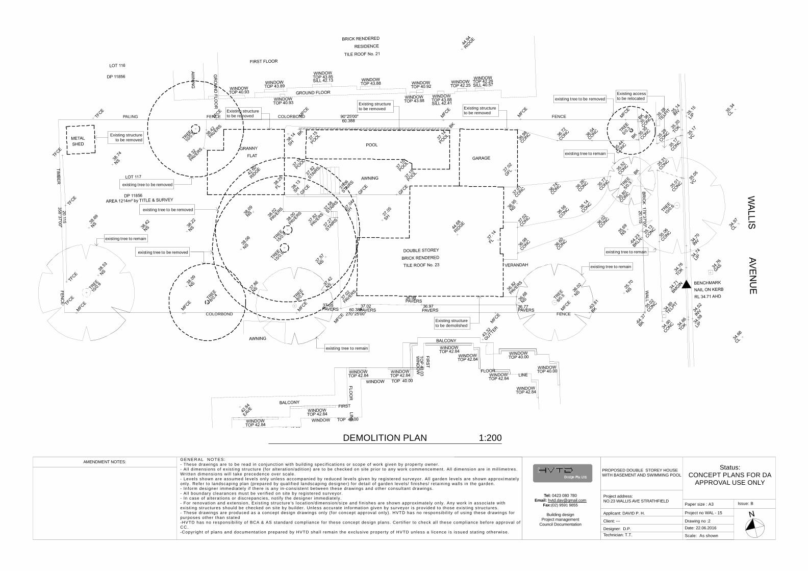
COLORBOND FENCE
PALING FENCE COLORBOND FENCEExisting structureto be removed
Existing structureto be removed
Existing accessto be relocated
existing tree to be removed
existing tree to be removed
existing tree to be removed
Existing structureto be demolished
Existing structureto be removed
existing tree to remain
existing tree to be removed
existing tree to remain
existing tree to remain
existing tree to remain
Existing structureto be removed
existing tree to remain
DEMOLITION PLAN 1:200
Status:CONCEPT PLANS FOR DA
APPROVAL USE ONLY
Scale: As shown
Issue: B
Project no WAL - 15
Technician: T.T.
Date: 22.06.2016Client: --- Drawing no :3
Designer: D.P.
AMENDMENT NOTES: GENER AL NO TES:- These drawings are to be read in conjunct ion with bui lding specif icat ions or scope of work given by property owner.- Al l dimensions of exis t ing structure ( for alterat ion/adit ion) are to be checked on site pr ior to any work commencement. All dimension are in mil l imetres.Writ ten dimensions wi l l take precedence over scale.- Levels shown are assumed leve ls only un less accompanied by reduced leve ls given by regis tered surveyor. Al l garden leve ls are shown approximatelyonly. Refer to landscaping plan (prepared by qual i f ied landscaping designer) for detai l of garden levels/ f inishes/ retaining walls in the garden.- In form designer immediately i f there is any in-consistent between these drawings and other consultant drawings.- Al l boundary clearances must be veri f ied on site by regis tered surveyor.- In case of a lterat ions or discrepancies, not i fy the designer immediately.- For renovat ion and extension, Exis t ing structure 's locat ion/dimension/s ize and f in ishes are shown approximate ly only. Any work in associate withexis t ing structures should be checked on site by bu i lder. Unless accurate information given by surveyor is prov ided to those ex is t ing structures.- These drawings are produced as a concept design drawings only ( for concept approval only). HVTD has no responsibi l i ty of using these drawings forpurposes other than stated-HVTD has no responsibi l i ty o f BCA & AS standard compliance for these concept design plans. Cert i f ier to check al l these compliance before approval o fCC.-Copyr ight of plans and documentat ion prepared by HVTD shal l remain the exclusive property of HVTD unless a l icence is issued stat ing otherwise.
Paper size : A3
PROPOSED DOUBLE STOREY HOUSEWITH BASEMENT AND SWIMMING POOL
Project address:NO.23 WALLIS AVE STRATHFIELD
Applicant: DAVID P. H.
Tel: 0423 080 780Email: [email protected]
Fax:(02) 9591 9855
Building designProject management
Council Documentation
HW
RWT
DrivewayRefer to traffic
engineerfor details.
DrivewayRefer to traffic
engineerfor details.
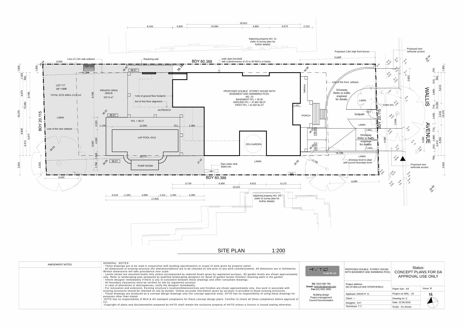
6,000
23,2215,734 6,400 4,915 6,173
17,835
20,6212,600 10,094 4,854 5,673 2,2108,164
1,421
1,139 12,000 312 4,384
6,000
1,000
3,218 1,345 4,985 1,511 2,391 4,384
1,000
537.9 m2
solar (gas boosted)with a performance of 31 to 35 RECs or better..
Retaining wall
line of first floor alignment
Line of 1.5m side setback
Letter box
Line of ground floor footprint
driveway level to alignwith council boundary level
Line of 9m front setback
Rain water tank3000l min
Proposed 1.8m high front fencesProposed newvehicular access
Proposed newvehicular access
Line of 6m rear setback
cloth line
PROPOSED DOUBLE STOREY HOUSE WITHBASEMENT AND SWIMMING POOL
NO. 23BASEMENT FFL + 35.00
GROUND FFL + 37.80/+38.37FIRST FFL + 41.00/+41.57
LAWN
ZEN GARDEN
LAP POOL 4X12
38.07
PORCH
ALFRESCO
LAWN
LAWN
Adjoining property NO. 21(refer to survey plan for
further details)
Adjoining property NO. 25(refer to survey plan for
further details)
FFL + 38.17
LAWN
LAWN
TOTAL SITE AREA 1214 m2
PUMP ROOM
PRIVATE OPENSPACE
bin
38.07 footpath
38.07
SITE PLAN 1:200
Status:CONCEPT PLANS FOR DA
APPROVAL USE ONLY
Scale: As shown
Issue: B
Project no WAL - 15
Technician: T.T.
Date: 22.06.2016Client: --- Drawing no :7
Designer: D.P.
AMENDMENT NOTES: GENER AL NO TES:- These drawings are to be read in conjunct ion with bui lding specif icat ions or scope of work given by property owner.- Al l dimensions of exis t ing structure ( for alterat ion/adit ion) are to be checked on site pr ior to any work commencement. All dimension are in mil l imetres.Writ ten dimensions wi l l take precedence over scale.- Levels shown are assumed leve ls only un less accompanied by reduced leve ls given by regis tered surveyor. Al l garden leve ls are shown approximatelyonly. Refer to landscaping plan (prepared by qual i f ied landscaping designer) for detai l of garden levels/ f inishes/ retaining walls in the garden.- In form designer immediately i f there is any in-consistent between these drawings and other consultant drawings.- Al l boundary clearances must be veri f ied on site by regis tered surveyor.- In case of a lterat ions or discrepancies, not i fy the designer immediately.- For renovat ion and extension, Exis t ing structure 's locat ion/dimension/s ize and f in ishes are shown approximate ly only. Any work in associate withexis t ing structures should be checked on site by bu i lder. Unless accurate information given by surveyor is prov ided to those ex is t ing structures.- These drawings are produced as a concept design drawings only ( for concept approval only). HVTD has no responsibi l i ty of using these drawings forpurposes other than stated-HVTD has no responsibi l i ty o f BCA & AS standard compliance for these concept design plans. Cert i f ier to check al l these compliance before approval o fCC.-Copyr ight of plans and documentat ion prepared by HVTD shal l remain the exclusive property of HVTD unless a l icence is issued stat ing otherwise.
Paper size : A3
PROPOSED DOUBLE STOREY HOUSEWITH BASEMENT AND SWIMMING POOL
Project address:NO.23 WALLIS AVE STRATHFIELD
Applicant: DAVID P. H.
Tel: 0423 080 780Email: [email protected]
Fax:(02) 9591 9855
Building designProject management
Council Documentation
B5
A5
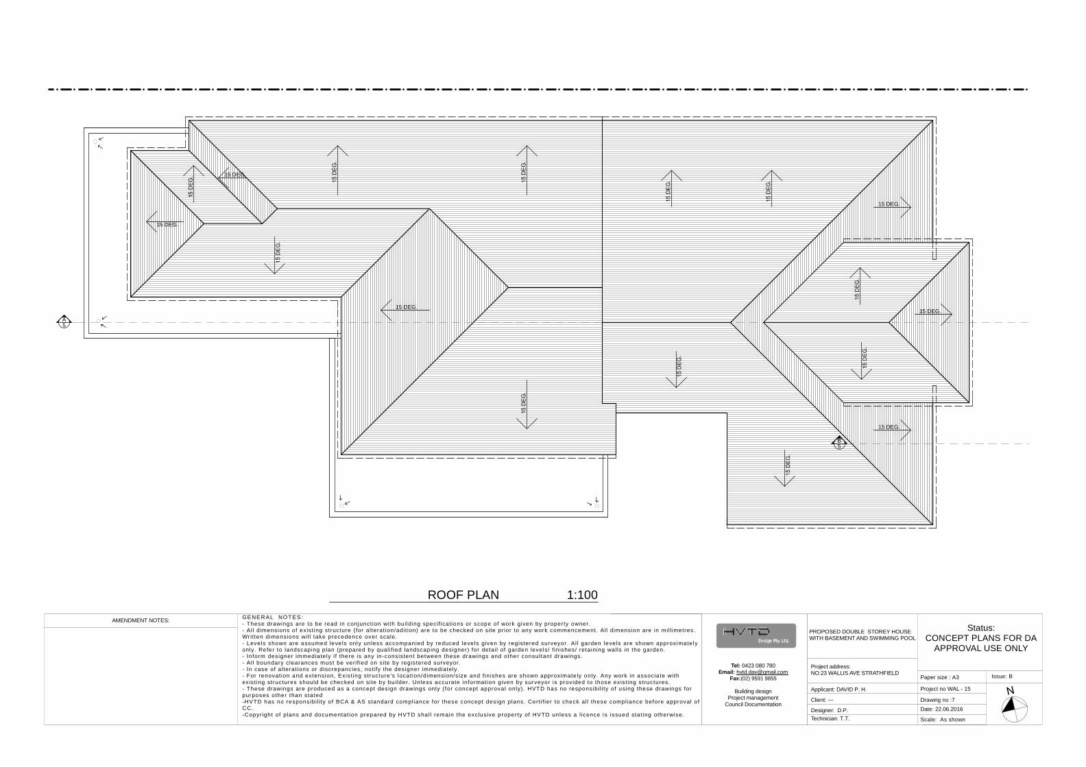
15 DEG.
15 DEG.
15 DEG.
15 DEG.
15 DEG.
15 DEG.
ROOF PLAN 1:100
Status:CONCEPT PLANS FOR DA
APPROVAL USE ONLY
Scale: As shown
Issue: B
Project no WAL - 15
Technician: T.T.
Date: 22.06.2016Client: --- Drawing no :12
Designer: D.P.
AMENDMENT NOTES: GENER AL NO TES:- These drawings are to be read in conjunct ion with bui lding specif icat ions or scope of work given by property owner.- Al l dimensions of exis t ing structure ( for alterat ion/adit ion) are to be checked on site pr ior to any work commencement. All dimension are in mil l imetres.Writ ten dimensions wi l l take precedence over scale.- Levels shown are assumed leve ls only un less accompanied by reduced leve ls given by regis tered surveyor. Al l garden leve ls are shown approximatelyonly. Refer to landscaping plan (prepared by qual i f ied landscaping designer) for detai l of garden levels/ f inishes/ retaining walls in the garden.- In form designer immediately i f there is any in-consistent between these drawings and other consultant drawings.- Al l boundary clearances must be veri f ied on site by regis tered surveyor.- In case of a lterat ions or discrepancies, not i fy the designer immediately.- For renovat ion and extension, Exis t ing structure 's locat ion/dimension/s ize and f in ishes are shown approximate ly only. Any work in associate withexis t ing structures should be checked on site by bu i lder. Unless accurate information given by surveyor is prov ided to those ex is t ing structures.- These drawings are produced as a concept design drawings only ( for concept approval only). HVTD has no responsibi l i ty of using these drawings forpurposes other than stated-HVTD has no responsibi l i ty o f BCA & AS standard compliance for these concept design plans. Cert i f ier to check al l these compliance before approval o fCC.-Copyr ight of plans and documentat ion prepared by HVTD shal l remain the exclusive property of HVTD unless a l icence is issued stat ing otherwise.
Paper size : A3
PROPOSED DOUBLE STOREY HOUSEWITH BASEMENT AND SWIMMING POOL
Project address:NO.23 WALLIS AVE STRATHFIELD
Applicant: DAVID P. H.
Tel: 0423 080 780Email: [email protected]
Fax:(02) 9591 9855
Building designProject management
Council Documentation
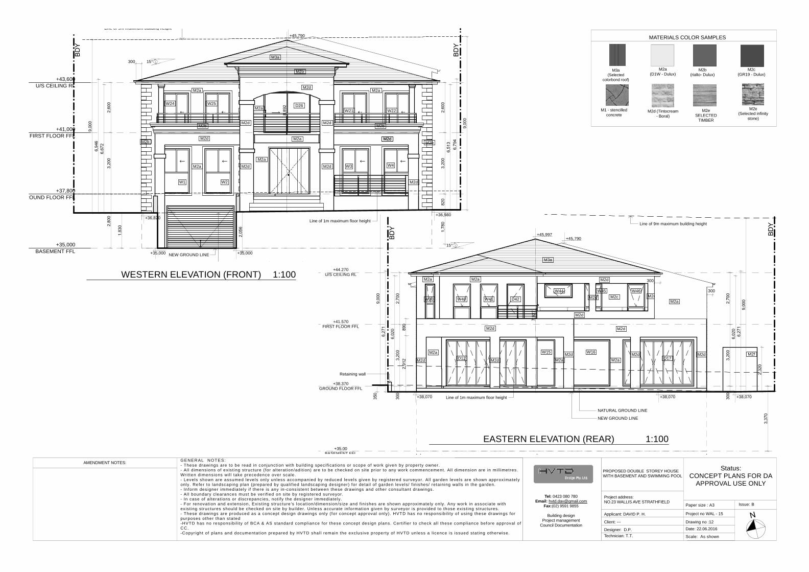
+36,820+36,980
300
+45,790
+35,000 +35,000
15°
Line of 9m maximum building height
NEW GROUND LINE
Line of 1m maximum floor height
W1 W2
W3 W4
W24 W25 D26W21 W22
M3a
M2d
M2d
M2d
M2d
M2dM2dM2a
M2d
M2bM2b
M2b
M2b M2b
M2a
M2a
M2a M2a
M2a
M2d M2d
M2a
+35,000BASEMENT FFL
+37,800ROUND FLOOR FFL
+41,000FIRST FLOOR FFL
+43,600U/S CEILING RL
300
+45,790
+38,070 +38,070+38,070
+45,997
15°
NATURAL GROUND LINE
Line of 9m maximum building height
NEW GROUND LINE
Retaining wall
Line of 1m maximum floor height
W30
M2f
M2d
M2d
M2a
M2a
+38.370GROUND FLOOR FFL
+41.570FIRST FLOOR FFL
M2c
M2a
M2a
M2aM2dM2dM2d
M2d
M2dM2d
M2dM2d
M2d
D12W15 W16
D17
W40 W41 D42
W44 W45 W46
+44.270U/S CEILING RL
M3a
+35.00BASEMENT FFL
M2a
300WESTERN ELEVATION (FRONT) 1:100
EASTERN ELEVATION (REAR) 1:100
MATERIALS COLOR SAMPLES
M3a(Selected
colorbond roof)
M2eSELECTED
TIMBER
M2a(D1W - Dulux)
M2c(GR19 - Dulux)
M1 - stencilledconcrete
M2b(rialto- Dulux)
M2d (Tintocream- Boral)
M2e(Selected infinity
stone)
Status:CONCEPT PLANS FOR DA
APPROVAL USE ONLY
Scale: As shown
Issue: B
Project no WAL - 15
Technician: T.T.
Date: 22.06.2016Client: --- Drawing no :13
Designer: D.P.
AMENDMENT NOTES: GENER AL NO TES:- These drawings are to be read in conjunct ion with bui lding specif icat ions or scope of work given by property owner.- Al l dimensions of exis t ing structure ( for alterat ion/adit ion) are to be checked on site pr ior to any work commencement. All dimension are in mil l imetres.Writ ten dimensions wi l l take precedence over scale.- Levels shown are assumed leve ls only un less accompanied by reduced leve ls given by regis tered surveyor. Al l garden leve ls are shown approximatelyonly. Refer to landscaping plan (prepared by qual i f ied landscaping designer) for detai l of garden levels/ f inishes/ retaining walls in the garden.- In form designer immediately i f there is any in-consistent between these drawings and other consultant drawings.- Al l boundary clearances must be veri f ied on site by regis tered surveyor.- In case of a lterat ions or discrepancies, not i fy the designer immediately.- For renovat ion and extension, Exis t ing structure 's locat ion/dimension/s ize and f in ishes are shown approximate ly only. Any work in associate withexis t ing structures should be checked on site by bu i lder. Unless accurate information given by surveyor is prov ided to those ex is t ing structures.- These drawings are produced as a concept design drawings only ( for concept approval only). HVTD has no responsibi l i ty of using these drawings forpurposes other than stated-HVTD has no responsibi l i ty o f BCA & AS standard compliance for these concept design plans. Cert i f ier to check al l these compliance before approval o fCC.-Copyr ight of plans and documentat ion prepared by HVTD shal l remain the exclusive property of HVTD unless a l icence is issued stat ing otherwise.
Paper size : A3
PROPOSED DOUBLE STOREY HOUSEWITH BASEMENT AND SWIMMING POOL
Project address:NO.23 WALLIS AVE STRATHFIELD
Applicant: DAVID P. H.
Tel: 0423 080 780Email: [email protected]
Fax:(02) 9591 9855
Building designProject management
Council Documentation
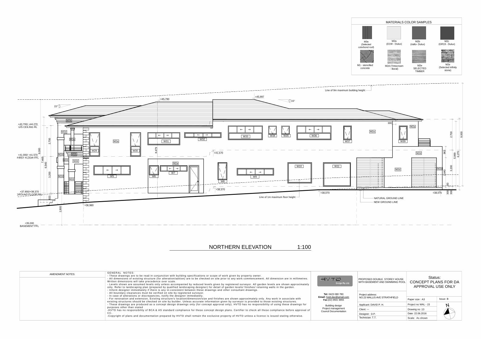
+36,980
+45,790
+41,570
+38,370+38,070+38,070
+45,997
300
15°
15°
NATURAL GROUND LINE
Line of 9m maximum building height
NEW GROUND LINE
Line of 1m maximum floor height
M2d
M2d
M2d
M2a
M2bM2b
M2b
+37.800/+38.370GROUND FLOOR FFL
+41.000/ +41.570FIRST FLOOR FFL
+35.000BASEMENT FFL
M2dM2d
M2d
+43.700/ +44.270U/S CEILING RL
M2a
M2a
M2a
M2a
M2d
M2dM2d
W5 W6W7
W8
W9
W10 W11
W29 W30
W31W32
W33 W34 W35 W36
W37 W39
NORTHERN ELEVATION 1:100
MATERIALS COLOR SAMPLES
M3a(Selected
colorbond roof)
M2eSELECTED
TIMBER
M2a(D1W - Dulux)
M2c(GR19 - Dulux)
M1 - stencilledconcrete
M2b(rialto- Dulux)
M2d (Tintocream- Boral)
M2e(Selected infinity
stone)
Status:CONCEPT PLANS FOR DA
APPROVAL USE ONLY
Scale: As shown
Issue: B
Project no WAL - 15
Technician: T.T.
Date: 22.06.2016Client: --- Drawing no :14
Designer: D.P.
AMENDMENT NOTES: GENER AL NO TES:- These drawings are to be read in conjunct ion with bui lding specif icat ions or scope of work given by property owner.- Al l dimensions of exis t ing structure ( for alterat ion/adit ion) are to be checked on site pr ior to any work commencement. All dimension are in mil l imetres.Writ ten dimensions wi l l take precedence over scale.- Levels shown are assumed leve ls only un less accompanied by reduced leve ls given by regis tered surveyor. Al l garden leve ls are shown approximatelyonly. Refer to landscaping plan (prepared by qual i f ied landscaping designer) for detai l of garden levels/ f inishes/ retaining walls in the garden.- In form designer immediately i f there is any in-consistent between these drawings and other consultant drawings.- Al l boundary clearances must be veri f ied on site by regis tered surveyor.- In case of a lterat ions or discrepancies, not i fy the designer immediately.- For renovat ion and extension, Exis t ing structure 's locat ion/dimension/s ize and f in ishes are shown approximate ly only. Any work in associate withexis t ing structures should be checked on site by bu i lder. Unless accurate information given by surveyor is prov ided to those ex is t ing structures.- These drawings are produced as a concept design drawings only ( for concept approval only). HVTD has no responsibi l i ty of using these drawings forpurposes other than stated-HVTD has no responsibi l i ty o f BCA & AS standard compliance for these concept design plans. Cert i f ier to check al l these compliance before approval o fCC.-Copyr ight of plans and documentat ion prepared by HVTD shal l remain the exclusive property of HVTD unless a l icence is issued stat ing otherwise.
Paper size : A3
PROPOSED DOUBLE STOREY HOUSEWITH BASEMENT AND SWIMMING POOL
Project address:NO.23 WALLIS AVE STRATHFIELD
Applicant: DAVID P. H.
Tel: 0423 080 780Email: [email protected]
Fax:(02) 9591 9855
Building designProject management
Council Documentation
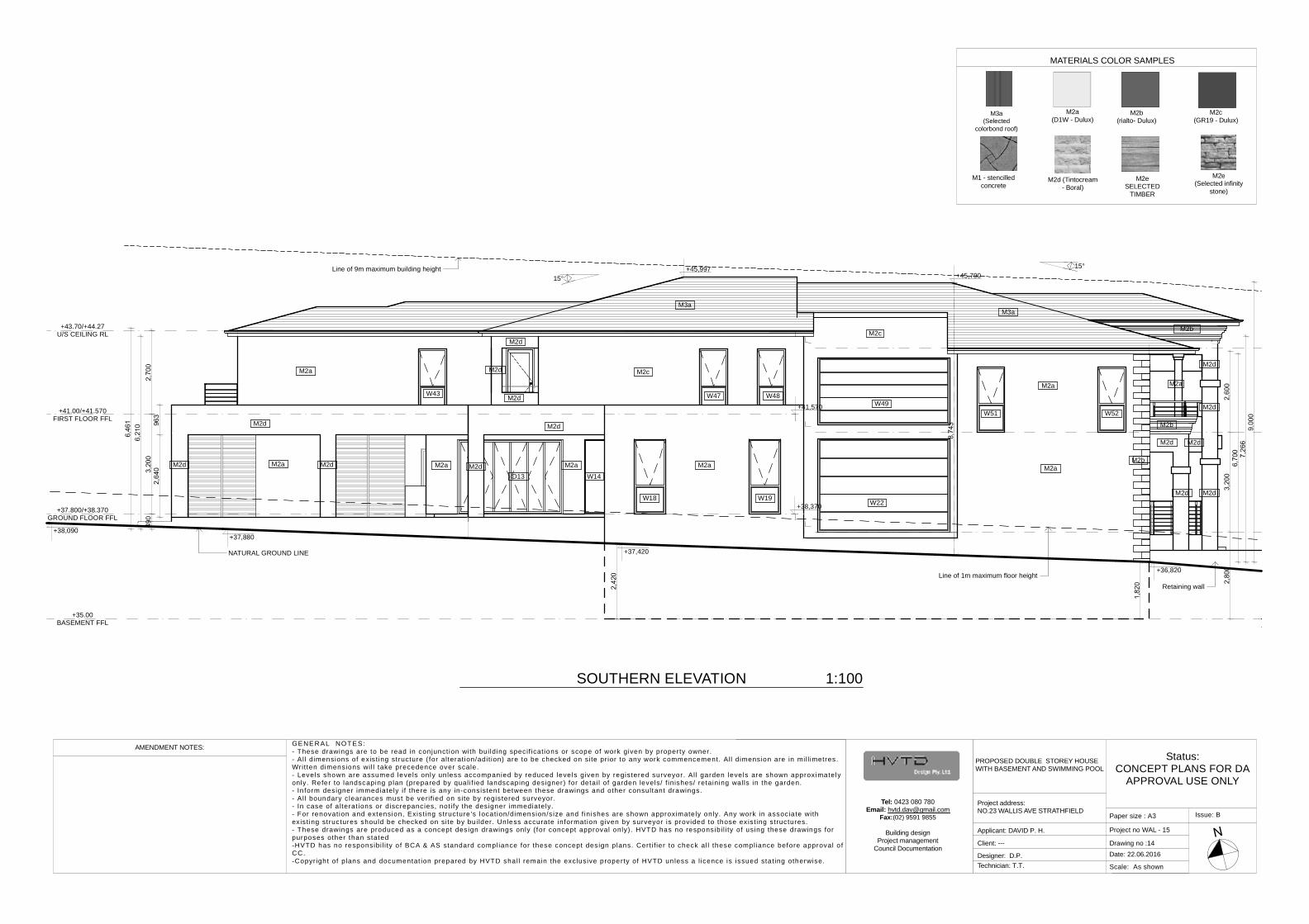
+37,420
+36,820
+45,790
+38,090
+41,570
+38,370
+37,880
+45,997 15°
15°
NATURAL GROUND LINE
Line of 9m maximum building height
Retaining wallLine of 1m maximum floor height
W22
W49
M2aM2b
M2b
M2bM2c
M2dM2d
M2d
M2d
M2d
M2a
M3a
+37.800/+38.370GROUND FLOOR FFL
+41.00/+41.570FIRST FLOOR FFL
M2d
M2d
M2dM2d
M2d M2d
+43.70/+44.27U/S CEILING RL
M2a
M2d
M2d
M2d
M2a M2a M2a
M2a
M2a
M2c
M3a
D13 W14
W18 W19
W43 W47 W48
W51 W52
+35.00BASEMENT FFL
SOUTHERN ELEVATION 1:100
MATERIALS COLOR SAMPLES
M3a(Selected
colorbond roof)
M2eSELECTED
TIMBER
M2a(D1W - Dulux)
M2c(GR19 - Dulux)
M1 - stencilledconcrete
M2b(rialto- Dulux)
M2d (Tintocream- Boral)
M2e(Selected infinity
stone)
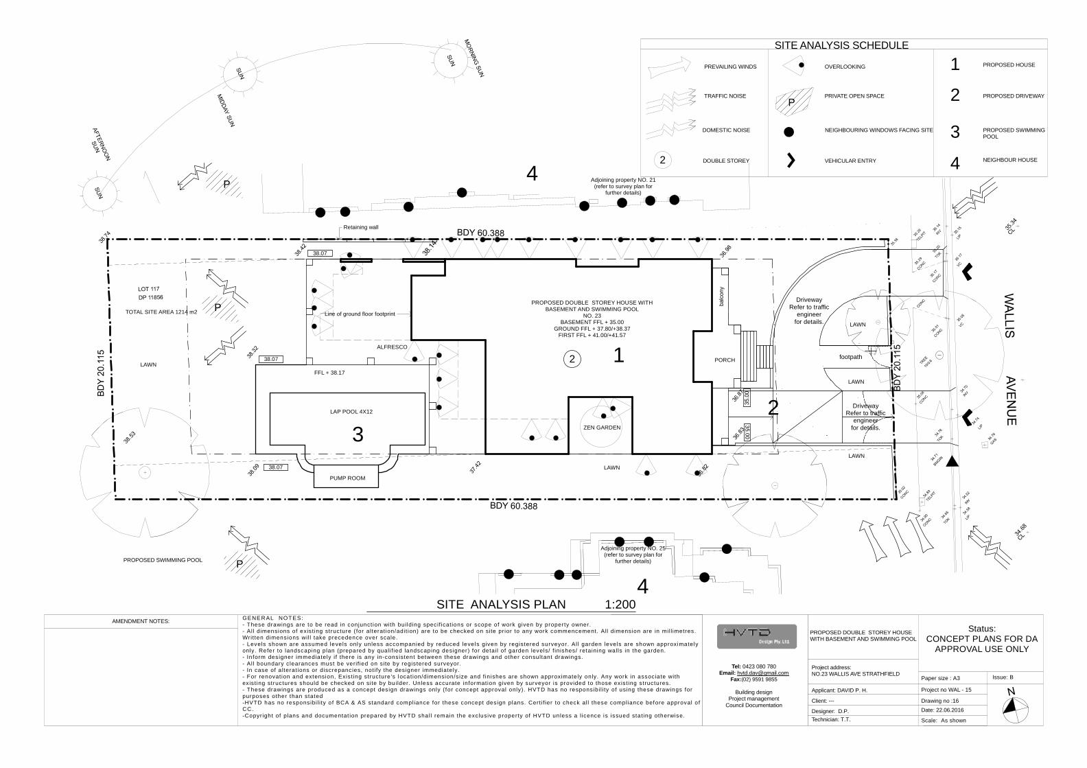
1
2
3
4
PROPOSED HOUSE
PROPOSED DRIVEWAY
NEIGHBOUR HOUSEVEHICULAR ENTRY
NEIGHBOURING WINDOWS FACING SITE
PPRIVATE OPEN SPACE
OVERLOOKING
2 DOUBLE STOREY
DOMESTIC NOISE
TRAFFIC NOISE
PREVAILING WINDS
SITE ANALYSIS SCHEDULE
Status:CONCEPT PLANS FOR DA
APPROVAL USE ONLY
Scale: As shown
Issue: B
Project no WAL - 15
Technician: T.T.
Date: 22.06.2016Client: --- Drawing no :16
Designer: D.P.
AMENDMENT NOTES: GENER AL NO TES:- These drawings are to be read in conjunct ion with bui lding specif icat ions or scope of work given by property owner.- Al l dimensions of exis t ing structure ( for alterat ion/adit ion) are to be checked on site pr ior to any work commencement. All dimension are in mil l imetres.Writ ten dimensions wi l l take precedence over scale.- Levels shown are assumed leve ls only un less accompanied by reduced leve ls given by regis tered surveyor. Al l garden leve ls are shown approximatelyonly. Refer to landscaping plan (prepared by qual i f ied landscaping designer) for detai l of garden levels/ f inishes/ retaining walls in the garden.- In form designer immediately i f there is any in-consistent between these drawings and other consultant drawings.- Al l boundary clearances must be veri f ied on site by regis tered surveyor.- In case of a lterat ions or discrepancies, not i fy the designer immediately.- For renovat ion and extension, Exis t ing structure 's locat ion/dimension/s ize and f in ishes are shown approximate ly only. Any work in associate withexis t ing structures should be checked on site by bu i lder. Unless accurate information given by surveyor is prov ided to those ex is t ing structures.- These drawings are produced as a concept design drawings only ( for concept approval only). HVTD has no responsibi l i ty of using these drawings forpurposes other than stated-HVTD has no responsibi l i ty o f BCA & AS standard compliance for these concept design plans. Cert i f ier to check al l these compliance before approval o fCC.-Copyr ight of plans and documentat ion prepared by HVTD shal l remain the exclusive property of HVTD unless a l icence is issued stat ing otherwise.
Paper size : A3
PROPOSED DOUBLE STOREY HOUSEWITH BASEMENT AND SWIMMING POOL
Project address:NO.23 WALLIS AVE STRATHFIELD
Applicant: DAVID P. H.
PROPOSED SWIMMING POOL
PROPOSED SWIMMINGPOOL
Tel: 0423 080 780Email: [email protected]
Fax:(02) 9591 9855
Building designProject management
Council Documentation
DrivewayRefer to traffic
engineerfor details.
DrivewayRefer to traffic
engineerfor details.
Retaining wall
Line of ground floor footprint
PROPOSED DOUBLE STOREY HOUSE WITHBASEMENT AND SWIMMING POOL
NO. 23BASEMENT FFL + 35.00
GROUND FFL + 37.80/+38.37FIRST FFL + 41.00/+41.57
LAWN
ZEN GARDEN
LAP POOL 4X12
38.07
PORCH
ALFRESCO
LAWN
LAWN
Adjoining property NO. 21(refer to survey plan for
further details)
Adjoining property NO. 25(refer to survey plan for
further details)
1
P
2
23
4
4
P
P
FFL + 38.17
LAWN
LAWN
TOTAL SITE AREA 1214 m2
PUMP ROOM
38.07 footpath
38.07
SITE ANALYSIS PLAN 1:200
Status:CONCEPT PLANS FOR DA
APPROVAL USE ONLY
Scale: As shown
Issue: B
Project no WAL - 15
Technician: T.T.
Date: 22.06.2016Client: --- Drawing no :17
Designer: D.P.
AMENDMENT NOTES: GENER AL NO TES:- These drawings are to be read in conjunct ion with bui lding specif icat ions or scope of work given by property owner.- Al l dimensions of exis t ing structure ( for alterat ion/adit ion) are to be checked on site pr ior to any work commencement. All dimension are in mil l imetres.Writ ten dimensions wi l l take precedence over scale.- Levels shown are assumed leve ls only un less accompanied by reduced leve ls given by regis tered surveyor. Al l garden leve ls are shown approximatelyonly. Refer to landscaping plan (prepared by qual i f ied landscaping designer) for detai l of garden levels/ f inishes/ retaining walls in the garden.- In form designer immediately i f there is any in-consistent between these drawings and other consultant drawings.- Al l boundary clearances must be veri f ied on site by regis tered surveyor.- In case of a lterat ions or discrepancies, not i fy the designer immediately.- For renovat ion and extension, Exis t ing structure 's locat ion/dimension/s ize and f in ishes are shown approximate ly only. Any work in associate withexis t ing structures should be checked on site by bu i lder. Unless accurate information given by surveyor is prov ided to those ex is t ing structures.- These drawings are produced as a concept design drawings only ( for concept approval only). HVTD has no responsibi l i ty of using these drawings forpurposes other than stated-HVTD has no responsibi l i ty o f BCA & AS standard compliance for these concept design plans. Cert i f ier to check al l these compliance before approval o fCC.-Copyr ight of plans and documentat ion prepared by HVTD shal l remain the exclusive property of HVTD unless a l icence is issued stat ing otherwise.
Paper size : A3
PROPOSED DOUBLE STOREY HOUSEWITH BASEMENT AND SWIMMING POOL
Project address:NO.23 WALLIS AVE STRATHFIELD
Applicant: DAVID P. H.
Tel: 0423 080 780Email: [email protected]
Fax:(02) 9591 9855
Building designProject management
Council Documentation
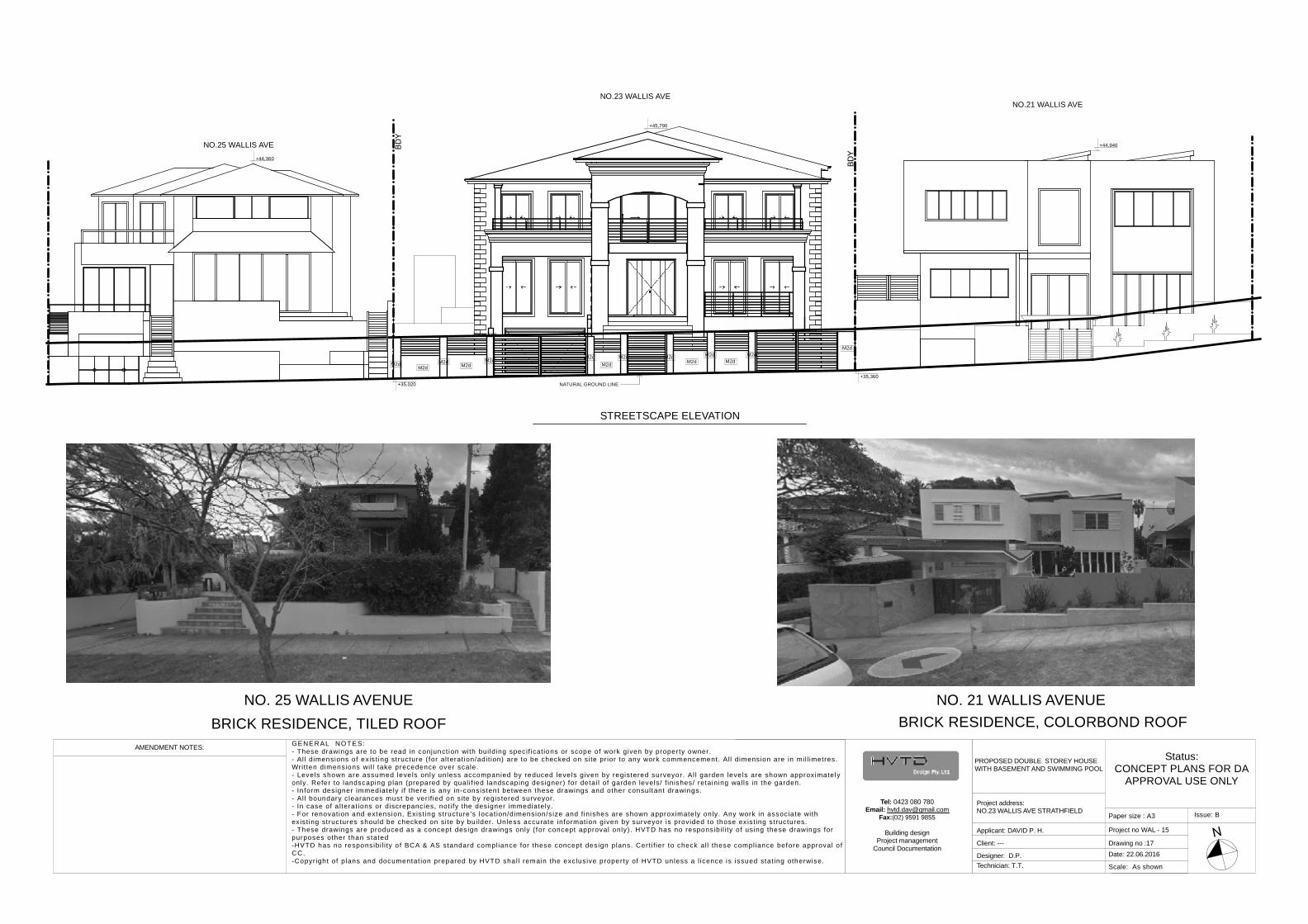
+35,360
+45,790
+37,153
+44,940
+44,360
NO.23 WALLIS AVENO.21 WALLIS AVE
NO.25 WALLIS AVE
+35,020 NATURAL GROUND LINE
M2dM2d
M2dM2d
M2dM2d
M2dM2d M2d
M2d M2dM2d
M2dM2d
STREETSCAPE ELEVATION
BRICK RESIDENCE, TILED ROOFNO. 25 WALLIS AVENUE
BRICK RESIDENCE, COLORBOND ROOFNO. 21 WALLIS AVENUE
Status:CONCEPT PLANS FOR DA
APPROVAL USE ONLY
Scale: As shown
Issue: B
Project no WAL - 15
Technician: T.T.
Date: 22.06.2016Client: --- Drawing no :18
Designer: D.P.
AMENDMENT NOTES: GENER AL NO TES:- These drawings are to be read in conjunct ion with bui lding specif icat ions or scope of work given by property owner.- Al l dimensions of exis t ing structure ( for alterat ion/adit ion) are to be checked on site pr ior to any work commencement. All dimension are in mil l imetres.Writ ten dimensions wi l l take precedence over scale.- Levels shown are assumed leve ls only un less accompanied by reduced leve ls given by regis tered surveyor. Al l garden leve ls are shown approximatelyonly. Refer to landscaping plan (prepared by qual i f ied landscaping designer) for detai l of garden levels/ f inishes/ retaining walls in the garden.- In form designer immediately i f there is any in-consistent between these drawings and other consultant drawings.- Al l boundary clearances must be veri f ied on site by regis tered surveyor.- In case of a lterat ions or discrepancies, not i fy the designer immediately.- For renovat ion and extension, Exis t ing structure 's locat ion/dimension/s ize and f in ishes are shown approximate ly only. Any work in associate withexis t ing structures should be checked on site by bu i lder. Unless accurate information given by surveyor is prov ided to those ex is t ing structures.- These drawings are produced as a concept design drawings only ( for concept approval only). HVTD has no responsibi l i ty of using these drawings forpurposes other than stated-HVTD has no responsibi l i ty o f BCA & AS standard compliance for these concept design plans. Cert i f ier to check al l these compliance before approval o fCC.-Copyr ight of plans and documentat ion prepared by HVTD shal l remain the exclusive property of HVTD unless a l icence is issued stat ing otherwise.
Paper size : A3
PROPOSED DOUBLE STOREY HOUSEWITH BASEMENT AND SWIMMING POOL
Project address:NO.23 WALLIS AVE STRATHFIELD
Applicant: DAVID P. H.
Tel: 0423 080 780Email: [email protected]
Fax:(02) 9591 9855
Building designProject management
Council Documentation
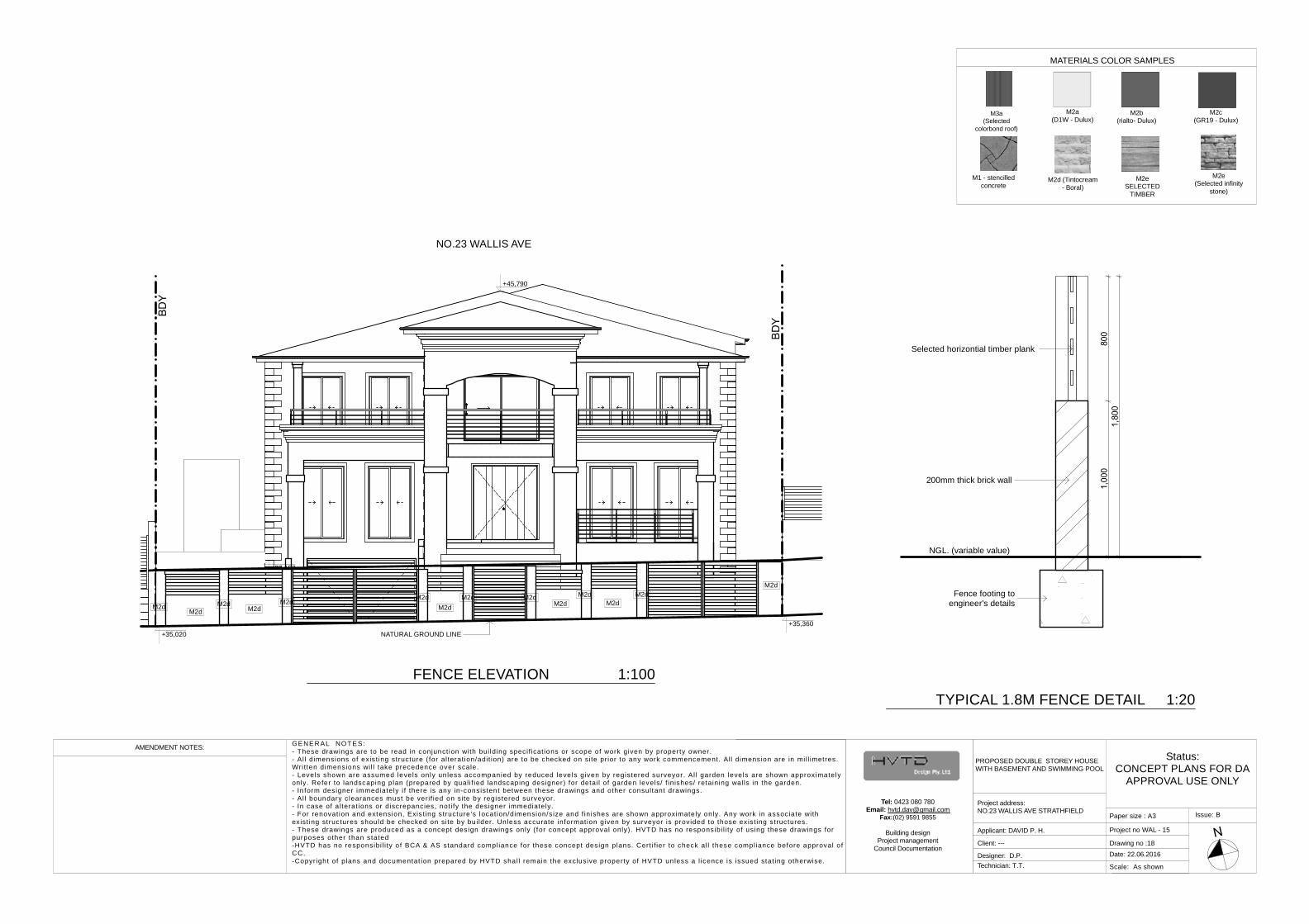
200mm thick brick wall
Selected horizontial timber plank
Fence footing toengineer's details
NGL. (variable value)
+35,360
+45,790
+37,153
NO.23 WALLIS AVE
+35,020 NATURAL GROUND LINE
M2dM2d
M2dM2d
M2dM2d
M2dM2d M2d
M2d M2dM2d
M2dM2d
TYPICAL 1.8M FENCE DETAIL 1:20
FENCE ELEVATION 1:100
MATERIALS COLOR SAMPLES
M3a(Selected
colorbond roof)
M2eSELECTED
TIMBER
M2a(D1W - Dulux)
M2c(GR19 - Dulux)
M1 - stencilledconcrete
M2b(rialto- Dulux)
M2d (Tintocream- Boral)
M2e(Selected infinity
stone)
Status:CONCEPT PLANS FOR DA
APPROVAL USE ONLY
Scale: As shown
Issue: B
Project no WAL - 15
Technician: T.T.
Date: 22.06.2016Client: --- Drawing no :19
Designer: D.P.
AMENDMENT NOTES: GENER AL NO TES:- These drawings are to be read in conjunct ion with bui lding specif icat ions or scope of work given by property owner.- Al l dimensions of exis t ing structure ( for alterat ion/adit ion) are to be checked on site pr ior to any work commencement. All dimension are in mil l imetres.Writ ten dimensions wi l l take precedence over scale.- Levels shown are assumed leve ls only un less accompanied by reduced leve ls given by regis tered surveyor. Al l garden leve ls are shown approximatelyonly. Refer to landscaping plan (prepared by qual i f ied landscaping designer) for detai l of garden levels/ f inishes/ retaining walls in the garden.- In form designer immediately i f there is any in-consistent between these drawings and other consultant drawings.- Al l boundary clearances must be veri f ied on site by regis tered surveyor.- In case of a lterat ions or discrepancies, not i fy the designer immediately.- For renovat ion and extension, Exis t ing structure 's locat ion/dimension/s ize and f in ishes are shown approximate ly only. Any work in associate withexis t ing structures should be checked on site by bu i lder. Unless accurate information given by surveyor is prov ided to those ex is t ing structures.- These drawings are produced as a concept design drawings only ( for concept approval only). HVTD has no responsibi l i ty of using these drawings forpurposes other than stated-HVTD has no responsibi l i ty o f BCA & AS standard compliance for these concept design plans. Cert i f ier to check al l these compliance before approval o fCC.-Copyr ight of plans and documentat ion prepared by HVTD shal l remain the exclusive property of HVTD unless a l icence is issued stat ing otherwise.
Paper size : A3
PROPOSED DOUBLE STOREY HOUSEWITH BASEMENT AND SWIMMING POOL
Project address:NO.23 WALLIS AVE STRATHFIELD
Applicant: DAVID P. H.
Tel: 0423 080 780Email: [email protected]
Fax:(02) 9591 9855
Building designProject management
Council Documentation
DrivewayRefer to traffic
engineerfor details.
DrivewayRefer to traffic
engineerfor details.
Retaining wall
Line of ground floor footprint
cloth line
PROPOSED DOUBLE STOREY HOUSE WITHBASEMENT AND SWIMMING POOL
NO. 23BASEMENT FFL + 35.00
GROUND FFL + 37.80/+38.37FIRST FFL + 41.00/+41.57
LAWN
ZEN GARDEN
LAP POOL 4X12
38.07
PORCH
ALFRESCO
LAWN
LAWN
Adjoining property NO. 21(refer to survey plan for
further details)
Adjoining property NO. 25(refer to survey plan for
further details)
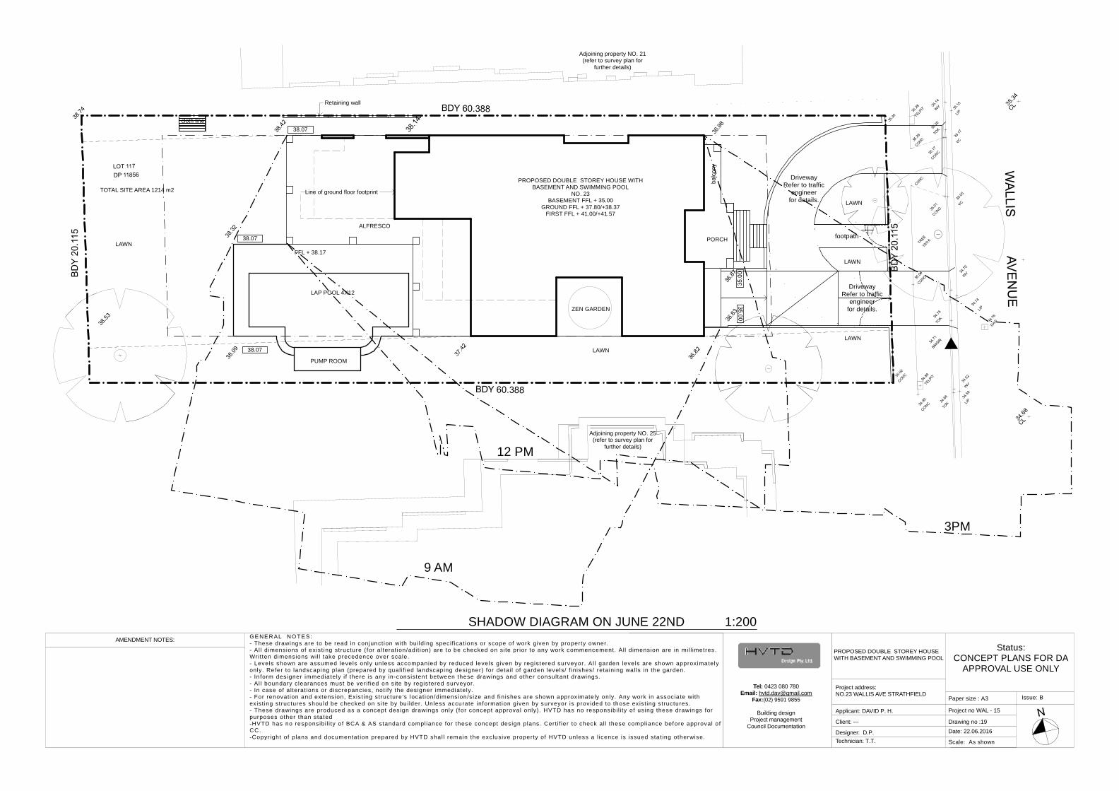
9 AM
12 PM
3PM
FFL + 38.17
LAWN
LAWN
TOTAL SITE AREA 1214 m2
PUMP ROOM
38.07 footpath
38.07
SHADOW DIAGRAM ON JUNE 22ND 1:200
LEGEND :
-UNDISTURBED VEGETATION :
- SILT FENCE :
- STOCK PILE ;
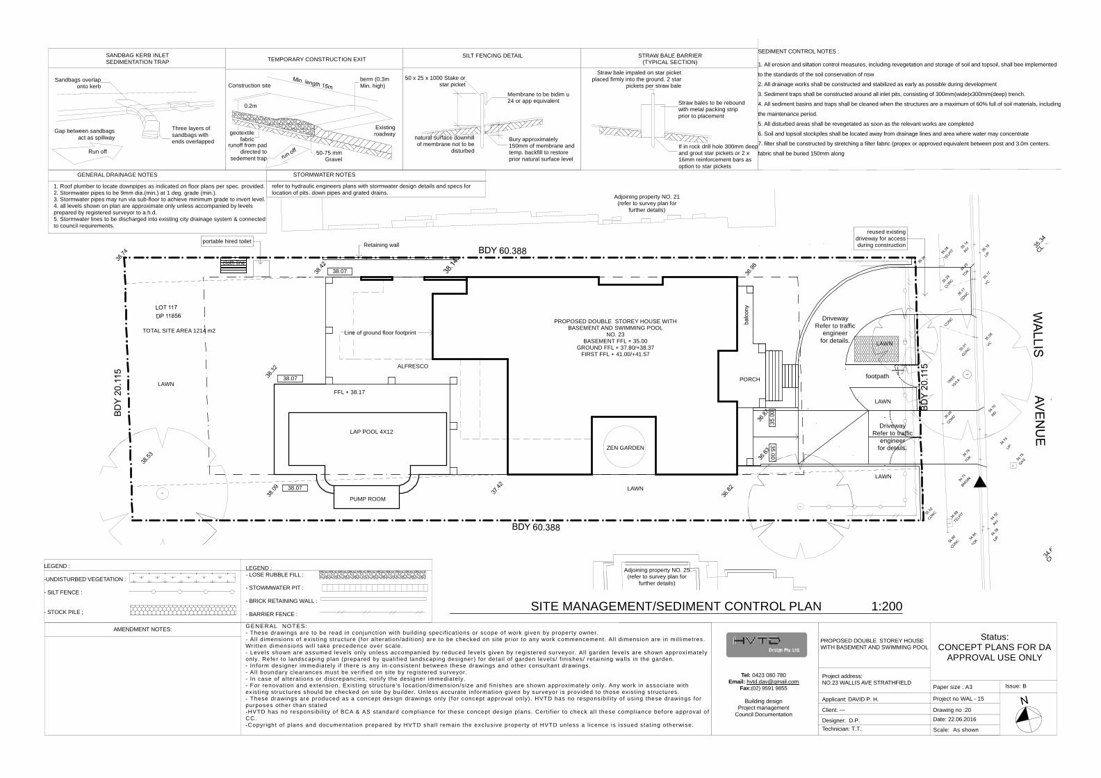
SEDIMENT CONTROL NOTES :
1. All erosion and siltation control measures, including revegetation and storage of soil and topsoil, shall bee implemented
to the standards of the soil conservation of nsw
2. All drainage works shall be constructed and stabilized as early as possible during development
3. Sediment traps shall be constructed around all inlet pits, consisting of 300mm(wide)x300mm(deep) trench.
4. All sediment basins and traps shall be cleaned when the structures are a maximum of 60% full of soil materials, including
the maintenance period.
5. All disturbed areas shall be revegetated as soon as the relevant works are completed
6. Soil and topsoil stockpiles shall be located away from drainage lines and area where water may concentrate
7. filter shall be constructed by stretching a filter fabric (propex or approved equivalent between post and 3.0m centers.
fabric shall be buried 150mm along
Straw bale impaled on star picketplaced firmly into the ground. 2 star
pickets per straw bale
Straw bales to be reboundwith metal packing stripprior to placement
If in rock drill hole 300mm deepand grout star pickets or 2 x16mm reinforcement bars asoption to star pickets
STRAW BALE BARRIER(TYPICAL SECTION)
SILT FENCING DETAIL
Membrane to be bidim u24 or app equivalent
50 x 25 x 1000 Stake orstar picket
natural surface downhillof membrane not to be
disturbed
Bury approximately150mm of membrane andtemp. backfill to restoreprior natural surface level
SANDBAG KERB INLETSEDIMENTATION TRAP
Sandbags overlaponto kerb
Three layers ofsandbags withends overlapped
Gap between sandbagsact as spillway
Run off
TEMPORARY CONSTRUCTION EXIT
Construction siteberm (0.3mMin. high)
geotextilefabric
runoff from paddirected to
sedement trap50-75 mm
Gravel
Existingroadway
0.2m
GENERAL DRAINAGE NOTES
1. Roof plumber to locate downpipes as indicated on floor plans per spec. provided.2. Stormwater pipes to be 9mm dia.(min.) at 1 deg. grade (min.).3. Stormwater pipes may run via sub-floor to achieve minimum grade to invert level.4. all levels shown on plan are approximate only unless accompanied by levelsprepared by registered surveyor to a.h.d.5. Stormwater lines to be discharged into existing city drainage system & connectedto council requirements.
STORMWATER NOTES
refer to hydraulic engineers plans with stormwater design details and specs forlocation of pits. down pipes and grated drains.
Status:CONCEPT PLANS FOR DA
APPROVAL USE ONLY
Scale: As shown
Issue: B
Project no WAL - 15
Technician: T.T.
Date: 22.06.2016Client: --- Drawing no :20
Designer: D.P.
AMENDMENT NOTES: GENER AL NO TES:- These drawings are to be read in conjunct ion with bui lding specif icat ions or scope of work given by property owner.- Al l dimensions of exis t ing structure ( for alterat ion/adit ion) are to be checked on site pr ior to any work commencement. All dimension are in mil l imetres.Writ ten dimensions wi l l take precedence over scale.- Levels shown are assumed leve ls only un less accompanied by reduced leve ls given by regis tered surveyor. Al l garden leve ls are shown approximatelyonly. Refer to landscaping plan (prepared by qual i f ied landscaping designer) for detai l of garden levels/ f inishes/ retaining walls in the garden.- In form designer immediately i f there is any in-consistent between these drawings and other consultant drawings.- Al l boundary clearances must be veri f ied on site by regis tered surveyor.- In case of a lterat ions or discrepancies, not i fy the designer immediately.- For renovat ion and extension, Exis t ing structure 's locat ion/dimension/s ize and f in ishes are shown approximate ly only. Any work in associate withexis t ing structures should be checked on site by bu i lder. Unless accurate information given by surveyor is prov ided to those ex is t ing structures.- These drawings are produced as a concept design drawings only ( for concept approval only). HVTD has no responsibi l i ty of using these drawings forpurposes other than stated-HVTD has no responsibi l i ty o f BCA & AS standard compliance for these concept design plans. Cert i f ier to check al l these compliance before approval o fCC.-Copyr ight of plans and documentat ion prepared by HVTD shal l remain the exclusive property of HVTD unless a l icence is issued stat ing otherwise.
Paper size : A3
PROPOSED DOUBLE STOREY HOUSEWITH BASEMENT AND SWIMMING POOL
Project address:NO.23 WALLIS AVE STRATHFIELD
Applicant: DAVID P. H.
Tel: 0423 080 780Email: [email protected]
Fax:(02) 9591 9855
Building designProject management
Council Documentation
LEGEND :- LOSE RUBBLE FILL :
- STOWMWATER PIT :
- BRICK RETAINING WALL :
- BARRIER FENCE :
DrivewayRefer to traffic
engineerfor details.
DrivewayRefer to traffic
engineerfor details.
Retaining wallportable hired toilet
reused existingdriveway for accessduring construction
Line of ground floor footprint
cloth line
PROPOSED DOUBLE STOREY HOUSE WITHBASEMENT AND SWIMMING POOL
NO. 23BASEMENT FFL + 35.00
GROUND FFL + 37.80/+38.37FIRST FFL + 41.00/+41.57
LAWN
ZEN GARDEN
LAP POOL 4X12
38.07
PORCH
ALFRESCO
LAWN
LAWN
Adjoining property NO. 21(refer to survey plan for
further details)
Adjoining property NO. 25(refer to survey plan for
further details)
FFL + 38.17
LAWN
LAWN
TOTAL SITE AREA 1214 m2
PUMP ROOM
38.07 footpath
38.07
SITE MANAGEMENT/SEDIMENT CONTROL PLAN 1:200
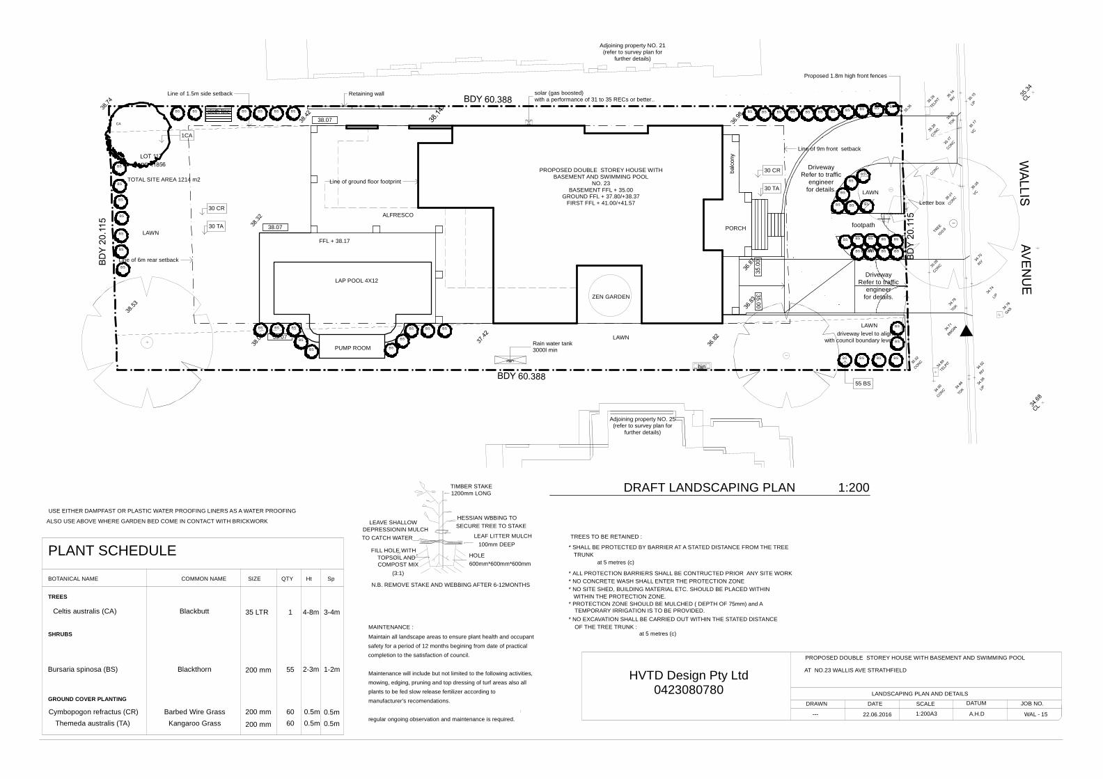
USE EITHER DAMPFAST OR PLASTIC WATER PROOFING LINERS AS A WATER PROOFING
ALSO USE ABOVE WHERE GARDEN BED COME IN CONTACT WITH BRICKWORK
MAINTENANCE :
manufacturer's recomendations.
regular ongoing observation and maintenance is required.
mowing, edging, pruning and top dressing of turf areas also allplants to be fed slow release fertilizer according to
Maintenance will include but not limited to the following activities,
Maintain all landscape areas to ensure plant health and occupant
completion to the satisfaction of council.safety for a period of 12 months begining from date of practical
* ALL PROTECTION BARRIERS SHALL BE CONTRUCTED PRIOR ANY SITE WORK
at 5 metres (c)
* NO SITE SHED, BUILDING MATERIAL ETC. SHOULD BE PLACED WITHIN
* PROTECTION ZONE SHOULD BE MULCHED ( DEPTH OF 75mm) and A
* NO EXCAVATION SHALL BE CARRIED OUT WITHIN THE STATED DISTANCETEMPORARY IRRIGATION IS TO BE PROVIDED.
WITHIN THE PROTECTION ZONE.
* NO CONCRETE WASH SHALL ENTER THE PROTECTION ZONE
OF THE TREE TRUNK :
* SHALL BE PROTECTED BY BARRIER AT A STATED DISTANCE FROM THE TREE
at 5 metres (c)
TREES TO BE RETAINED :
TRUNK
LANDSCAPING PLAN AND DETAILS
A.H.D
DATUM
---
DRAWN
1:200A3
SCALEDATE
22.06.2016
JOB NO.
WAL - 15
N.B. REMOVE STAKE AND WEBBING AFTER 6-12MONTHS
(3:1)
TOPSOIL ANDCOMPOST MIX
FILL HOLE WITH
600mm*600mm*600mmHOLE
TIMBER STAKE1200mm LONG
SECURE TREE TO STAKEHESSIAN WBBING TO
TO CATCH WATERDEPRESSIONIN MULCH
LEAVE SHALLOW
100mm DEEPLEAF LITTER MULCH
AT NO.23 WALLIS AVE STRATHFIELD
PROPOSED DOUBLE STOREY HOUSE WITH BASEMENT AND SWIMMING POOL
Blackbutt 3-4mCeltis australis (CA) 4-8m
0.5m0.5m
35 LTR
2-3m 1-2m
0.5m0.5m
PLANT SCHEDULE
BOTANICAL NAME COMMON NAME SIZE QTY Ht Sp
TREES
SHRUBS
GROUND COVER PLANTING
Cymbopogon refractus (CR) Barbed Wire Grass 60
Bursaria spinosa (BS) Blackthorn
Themeda australis (TA) 60
200 mm
200 mm
200 mm
1
Kangaroo Grass
55 HVTD Design Pty Ltd0423080780
HW
RWT
BS
BS
BSBS
BS
BSBSBS
BSBSBSBS
BS
BS
BSBSBSBSBSBSBSBSBSBSBS
BSBS BS
BS
BSBS BS
BS
CA
BS
BS
BSBS
BS
BS
BS
BS
BS
BS
BS
BS BS BS BS
BSBSBS
BSBS
BS
BS
DrivewayRefer to traffic
engineerfor details.
DrivewayRefer to traffic
engineerfor details.
solar (gas boosted)with a performance of 31 to 35 RECs or better..
Retaining wallLine of 1.5m side setback
Letter box
1CA
55 BS
30 CR
30 TA
30 CR
30 TA
Line of ground floor footprint
driveway level to alignwith council boundary level
Line of 9m front setback
Rain water tank3000l min
Proposed 1.8m high front fences
Line of 6m rear setback
cloth line
PROPOSED DOUBLE STOREY HOUSE WITHBASEMENT AND SWIMMING POOL
NO. 23BASEMENT FFL + 35.00
GROUND FFL + 37.80/+38.37FIRST FFL + 41.00/+41.57
LAWN
ZEN GARDEN
LAP POOL 4X12
38.07
PORCH
ALFRESCO
LAWN
LAWN
Adjoining property NO. 21(refer to survey plan for
further details)
Adjoining property NO. 25(refer to survey plan for
further details)
FFL + 38.17
LAWN
LAWN
TOTAL SITE AREA 1214 m2
PUMP ROOM
bin
38.07 footpath
38.07
DRAFT LANDSCAPING PLAN 1:200
Status:CONCEPT PLANS FOR DA
APPROVAL USE ONLY
Scale: As shown
Issue: B
Project no WAL - 15
Technician: T.T.
Date: 22.06.2016Client: --- Drawing no :22
Designer: D.P.
AMENDMENT NOTES: GENER AL NO TES:- These drawings are to be read in conjunct ion with bui lding specif icat ions or scope of work given by property owner.- Al l dimensions of exis t ing structure ( for alterat ion/adit ion) are to be checked on site pr ior to any work commencement. All dimension are in mil l imetres.Writ ten dimensions wi l l take precedence over scale.- Levels shown are assumed leve ls only un less accompanied by reduced leve ls given by regis tered surveyor. Al l garden leve ls are shown approximatelyonly. Refer to landscaping plan (prepared by qual i f ied landscaping designer) for detai l of garden levels/ f inishes/ retaining walls in the garden.- In form designer immediately i f there is any in-consistent between these drawings and other consultant drawings.- Al l boundary clearances must be veri f ied on site by regis tered surveyor.- In case of a lterat ions or discrepancies, not i fy the designer immediately.- For renovat ion and extension, Exis t ing structure 's locat ion/dimension/s ize and f in ishes are shown approximate ly only. Any work in associate withexis t ing structures should be checked on site by bu i lder. Unless accurate information given by surveyor is prov ided to those ex is t ing structures.- These drawings are produced as a concept design drawings only ( for concept approval only). HVTD has no responsibi l i ty of using these drawings forpurposes other than stated-HVTD has no responsibi l i ty o f BCA & AS standard compliance for these concept design plans. Cert i f ier to check al l these compliance before approval o fCC.-Copyr ight of plans and documentat ion prepared by HVTD shal l remain the exclusive property of HVTD unless a l icence is issued stat ing otherwise.
Paper size : A3
PROPOSED DOUBLE STOREY HOUSEWITH BASEMENT AND SWIMMING POOL
Project address:NO.23 WALLIS AVE STRATHFIELD
Applicant: DAVID P. H.
Tel: 0423 080 780Email: [email protected]
Fax:(02) 9591 9855
Building designProject management
Council Documentation
HW
RWT
DrivewayRefer to traffic
engineerfor details.
DrivewayRefer to traffic
engineerfor details.
6,000
23,2215,734 6,400 4,915 6,173
17,835
20,6212,600 10,094 4,854 5,673 2,2108,164
1,421
1,139 12,000 312 4,384
6,000
1,000
3,218 1,345 4,985 1,511 2,391 4,384
1,000
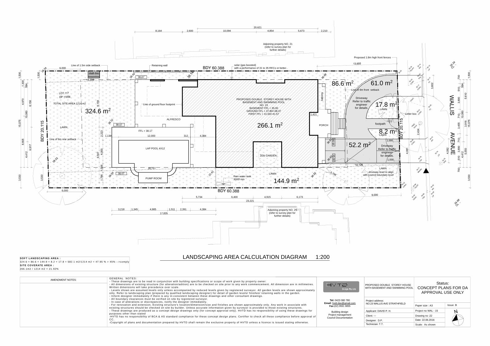
266.1 m2
324.6 m2
144.9 m2
8.2 m2
17.8 m2
86.6 m2 61.0 m2
52.2 m2
solar (gas boosted)with a performance of 31 to 35 RECs or better..
Retaining wallLine of 1.5m side setback
Letter box
Line of ground floor footprint
driveway level to alignwith council boundary level
Line of 9m front setback
Rain water tank3000l min
Proposed 1.8m high front fences
Line of 6m rear setback
cloth line
PROPOSED DOUBLE STOREY HOUSE WITHBASEMENT AND SWIMMING POOL
NO. 23BASEMENT FFL + 35.00
GROUND FFL + 37.80/+38.37FIRST FFL + 41.00/+41.57
LAWN
ZEN GARDEN
LAP POOL 4X12
38.07
PORCH
ALFRESCO
LAWN
LAWN
Adjoining property NO. 21(refer to survey plan for
further details)
Adjoining property NO. 25(refer to survey plan for
further details)
FFL + 38.17
LAWN
LAWN
TOTAL SITE AREA 1214 m2
PUMP ROOM
38.07 footpath
38.07
LANDSCAPING AREA CALCULATION DIAGRAM 1:200SO F T L ANDSCAPING AREA :324.6 + 86.6 + 144.9 + 8 .2 + 17.8 = 582.1 m2/1214 m2 = 47.95 % > 45% -->complySITE CO VERAT E AREA :266.1m2 / 1214 m2 = 21.92%
Recommended