Section 8
Driven Piles
8.1 ODOT Video, Part 7/12: Pile Foundations 1
Pile Driving Equipment 4 Pile Types 16 Hammer Approval Letter 21 Construction Documents 23 Pile Record Book 24 Pile Acceptance Decision Chart 25


Driven Piles Section 8.1
January, 2014 1
View ODOT Video, Part 7/12
Pile Foundations
A Driven Pile is a deep foundation that is constructed by driving a concrete, steel or timber pile to support the anticipated loads in competent subsurface material.
What is a Driven Pile?

Driven Piles Section 8.1
January, 2014 2
End Bearing and Friction Piles
END BEARING LOAD
D
SANDS
SOFTCLAYS
ROCK
FRICTION
LOAD
SANDS
CLAYS
LOAD
LOAD
SANDS
CLAYS
LOA
SAND
Layer 4
Layer 3
Layer 2
Layer 1z1 RS1
+ RT
RT
z2 RS2
z3 RS3
z4 RS4
RSNQu =
Qu
Driven Piles Section 8.1
January, 2014 3
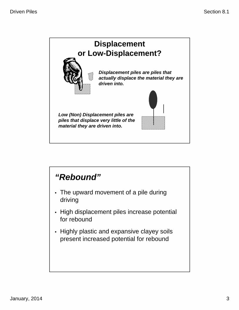
Displacement piles are piles that actually displace the material they are driven into.
Displacement or Low-Displacement?
Low (Non) Displacement piles are piles that displace very little of the material they are driven into.
““ReboundRebound””
• The upward movement of a pile during driving
• High displacement piles increase potential for rebound
• Highly plastic and expansive clayey soils present increased potential for rebound

Driven Piles Section 8.1
January, 2014 4
Pile Strength Vs. Time
Strength Gain (pile setup or “freeze”)
Piles can gain strength over time after they are driven in certain cohesive soils like stiff clays and clayey silts. This is due to the slow dissipation of excess pore water pressure that is created during pile driving.
Strength LosePiles can lose strength after driving in certain soils like very dense sands and gravels due to “relaxation” of the soil. Relaxation has to do with a change in soil structure after driving. The Geotechnical Engineer will determine if this effect applies at agiven site.
• Crane
• Hammer
• Cushions
• Leads
• Template
• Special Tools
Pile Driving Equipment

Driven Piles Section 8.1
January, 2014 5
CraneJIB LINES
JIB
JIB GANTRY
MAIN LINE
WHIP LINEBOOM
TURN TABLE
OUTRIGGERPADS
CABBOOMGANTRY
TOPPING LIFT
BOOM STOPPERS
YOKE
BOOM LINE
HEADACHEBALL
MAIN LOADBLOCK
SPLICE
(PENNENTS)
COUNTERWEIGHT
RADIUS
SingleActing
Drop (Gravity Hammers)
Vibratory
Air/Steam
SingleActing
DifferentialActing
DoubleActing
Diesel
SingleActing
DoubleActing
Hydraulic
DoubleActing
Hammers
Driven Piles Section 8.1
January, 2014 6
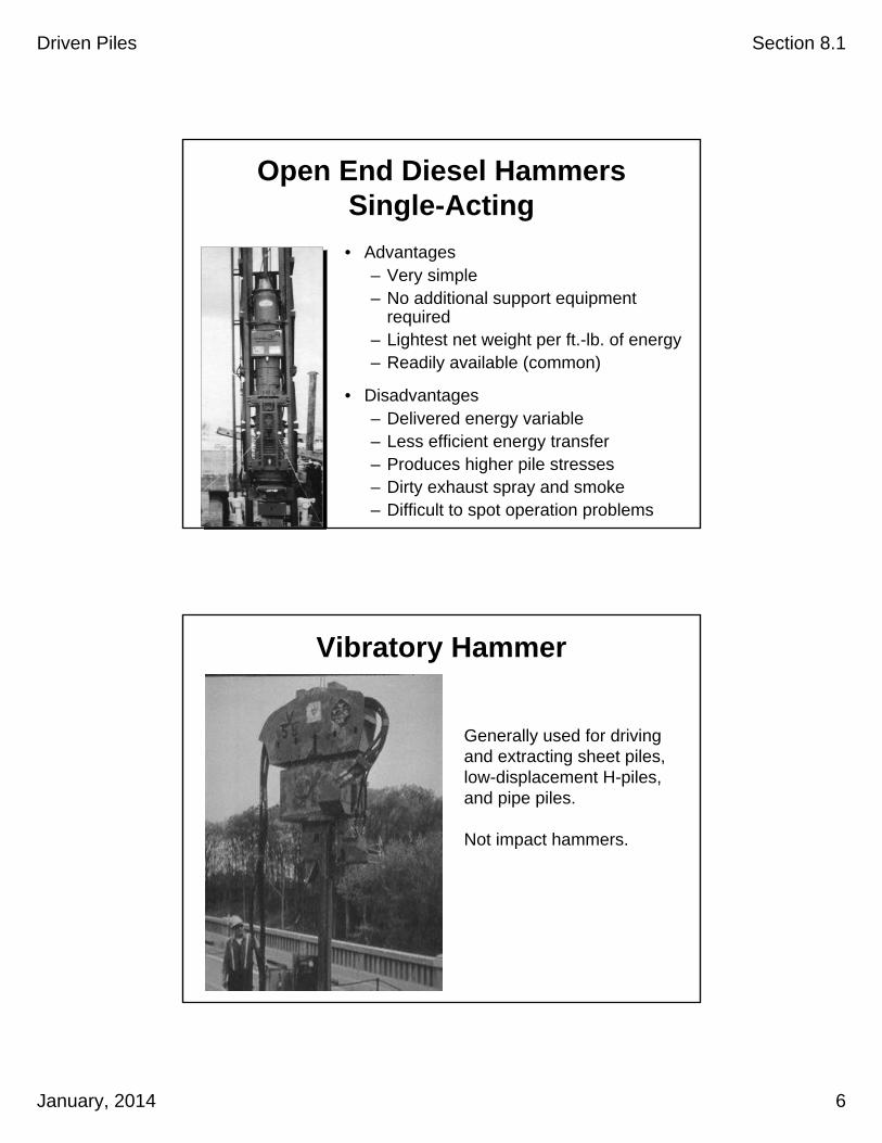
• Advantages– Very simple– No additional support equipment
required– Lightest net weight per ft.-lb. of energy– Readily available (common)
• Disadvantages– Delivered energy variable– Less efficient energy transfer– Produces higher pile stresses– Dirty exhaust spray and smoke– Difficult to spot operation problems
Open End Diesel Hammers Single-Acting
Generally used for driving and extracting sheet piles, low-displacement H-piles, and pipe piles.
Not impact hammers.
Vibratory Hammer

Driven Piles Section 8.1
January, 2014 7
Hammer Cushion(Cap Block)
Helmet
Pile Cushion
Concrete Pile
Striker Plate
Ram & Anvil
Hammer
Hammer Cushions
• Used on all impact hammers except gravity (drop) hammers
• Must be made of durable manufactured (man-made) materials
• Wood, wire rope and asbestos not allowed
• Striker plate must be used
Helmet
Pile Cushion
Concrete Pile
Striker Plate
Ram & Anvil
Hammer
Hammer Cushions (Cont’d)
• Inspected when beginning driving
• Inspected every 100 hours of driving
• Replaced when there is a reduction of thickness exceeding 25% of original thickness
Hammer Cushion(Cap Block)

Driven Piles Section 8.1
January, 2014 8
Hammer Cushions (Cont’d)
Hammer Cushion(Cap Block)
Helmet
Pile Cushion
Concrete Pile
Striker Plate
Ram & Anvil
Hammer
Helmet (Cap Block)
• Guided by leads, not free-swinging
• Must maintain proper alignment of hammer and pile
• Minimum 1 inch larger than pile

Driven Piles Section 8.1
January, 2014 9
Helmet (Cont’d)
Hammer Cushion(Cap Block)
Helmet
Pile Cushion
Concrete Pile
Striker Plate
Ram & Anvil
Hammer
Pile Cushion
• Used with concrete piles
• Minimum original thickness not less than 4 inches
• Replaced if compressed to more than one-half original thickness
• Replaced if starts to burn

Driven Piles Section 8.1
January, 2014 10
Pile Cushion (Cont’d)
HammerHammer
LeadsLeads
CraneCrane
TemplateTemplate
CushionsCushions
Special ToolsSpecial Tools
Pile Driving System Components – Leads

Driven Piles Section 8.1
January, 2014 11
BRACE
PILE
HAMMER
LEAD
BOOM
CRANEFixed at topand bottom
• Higher cost
• Maximum control of pile alignment
Fixed Lead System
• Low Cost
• Simple, mobile
• Some control of pile alignment
PILE
LEAD
HAMMER
CRANE
BOOM
Fixed eitherat top or
bottom but allowing vertical
movement
Semi-fixed Lead System

Driven Piles Section 8.1
January, 2014 12
• Low Cost
• Simple, mobile
• Less control of pile alignment
• Must be approved by The Engineer
PILE
HAMMER
LEAD
BOOM
CRANE
CABLE
Not fixed at topor bottom
Swinging Lead System
Required for offshore leads.
Maintains the pile and hammer in the correct location and position.
Templates

Driven Piles Section 8.1
January, 2014 13
Templates (Cont’d)C PlanLC LAs-built
Template Elev. is 5 ft.above Pile Cut-off Elev.
Pile Cut-off Elev.
Pile in correct position
C PlanL
15”
Pile in incorrect position
Special Tools
• Jets
• Drills (Preboring)
• Punches
• Followers
Driven Piles Section 8.1
January, 2014 14
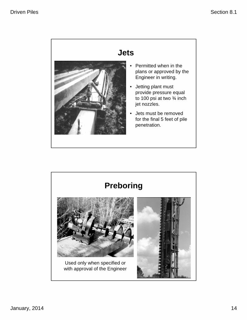
Jets
• Permitted when in the plans or approved by the Engineer in writing.
• Jetting plant must provide pressure equal to 100 psi at two ¾ inch jet nozzles.
• Jets must be removed for the final 5 feet of pile penetration.
Preboring
Used only when specified or with approval of the Engineer

Driven Piles Section 8.1
January, 2014 15
Combination Jet/Punch
Punch
Punches Aids for advancing pre-drilled holes through hard materials
Followers
• Generally used for water projects.
• Only when authorized in writing by Engineer or in contract documents.
• The first pile in each bent and every tenth pile thereafter must be driven without a follower.

Driven Piles Section 8.1
January, 2014 16
Pile Types
• Steel Pipe Piles
• Steel H-Piles
• Concrete Piles
• Timber Piles
• Cylinder Concrete Piles
• Composite Piles
• Steel Sheet Piles
Steel Pipe Piles• Most commonly
used in ODOT
• Driven either open or closed end
• Can be filled with concrete
Driven Piles Section 8.1
January, 2014 17
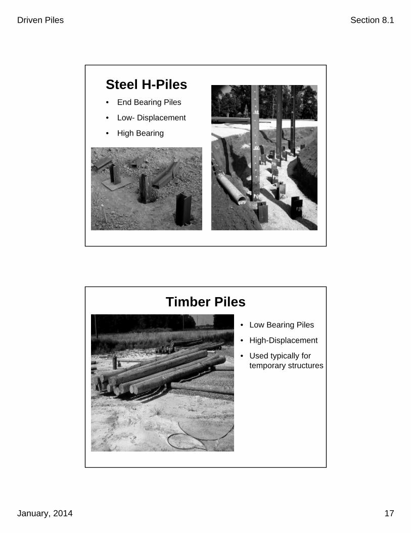
Steel H-Piles• End Bearing Piles
• Low- Displacement
• High Bearing
Timber Piles
• Low Bearing Piles
• High-Displacement
• Used typically for temporary structures

Driven Piles Section 8.1
January, 2014 18
Sheet Piles
• Utilized mostly for temporary retaining systems, such as shoring, cofferdams and bulkheads
• Driven using either impact or vibratory hammers
Pile Tip Attachments – Steel H-Pile
See Section 02520.10 (e) Reinforced Pile Tips
Driven Piles Section 8.1
January, 2014 19
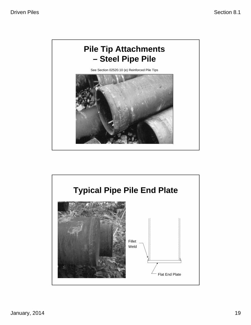
Pile Tip Attachments – Steel Pipe Pile
See Section 02520.10 (e) Reinforced Pile Tips
Typical Pipe Pile End Plate
Flat End Plate
Fillet
Weld
Driven Piles Section 8.1
January, 2014 20
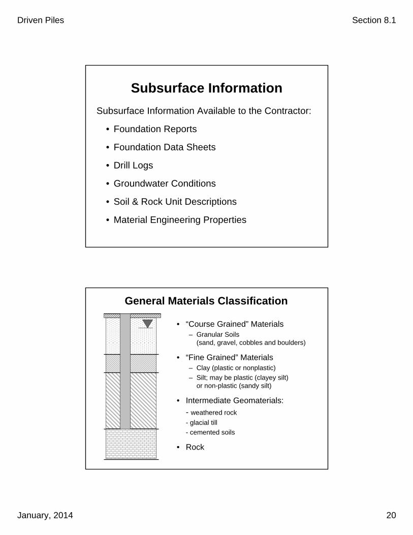
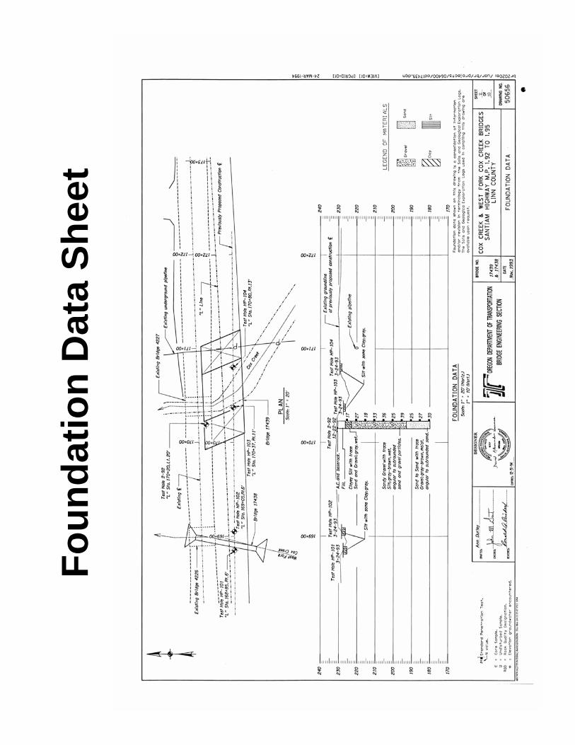
Subsurface Information
Subsurface Information Available to the Contractor:
• Foundation Reports
• Foundation Data Sheets
• Drill Logs
• Groundwater Conditions
• Soil & Rock Unit Descriptions
• Material Engineering Properties
• “Course Grained” Materials– Granular Soils
(sand, gravel, cobbles and boulders)
• “Fine Grained” Materials– Clay (plastic or nonplastic)
– Silt; may be plastic (clayey silt) or non-plastic (sandy silt)
• Intermediate Geomaterials:
- weathered rock
- glacial till
- cemented soils
• Rock
General Materials Classification

Fo
un
dat
ion
Dat
a S
hee
t


MILEPOST
CONTRACT NO STRUCTURE NAME AND NO.
PROJECT NAME (SECTION)
PROJECT MANAGER CONTRACTOR
COUNTY PILE DRIVING SUBCONTRACTOR (Piles Driven By):
TYPE OF LEADS:
OTHER (Provide Description):
LEAD DIMENSIONS Depth Width
MANUFACTURER MODEL TYPE
SERIAL NO. OWNER:
@ LENGTH OF STROKE RAM WT.
(KN-m)MODIFICATIONS
MATERIAL THICKNESS AREA
MATERIALS
TOTAL THICKNESS AREA
MODULUS OF ELASTICITY (E):
(MPa)COEFFICIENT OF RESTITUTION (e)
WEIGHT MODIFICATIONS
CUSHION MATERIALS AREA
NO OF LAYERS THICKNESS (EACH) TOTAL THICKNESS
MODULUS OF ELASTICITY (E): COEFFICIENT OF RESTITUTION (e)
(MPa)
PILE TYPE & SIZE Weight
LENGTH IN LEADS
WALL THICKNESS TAPER
NOMINAL PILE RESISTANCE ACCEPTANCE BY WAVE EQUATION
DESCRIPTION OF SPLICE
TIP TREATMENT DESCRIPTION (TYPE, MANUFACTURER, MODEL NO., ETC.)
SUBMITTED BY: DATE
(KN)
(mm)
(mm.) (mm2)
NOTE: If mandrel is used to drive the pile, attach separate manufacturer's detail sheet(s) including weight and dimensions.
ALLCOMPONENTS `
(mm2)
PILE AND DRIVING EQUIPMENT DATA
HIGHWAY
(m)
(KN/m)
(mm.) (mm.)
(KN)RATED ENERGY
(m)
(KN)
(mm.)
(mm2)
Yes No
Fixed Semi-Fixed Swinging
734-2608 (8-2009)

Driven Piles Section 8.1
January, 2014 21
Pile Hammer Acceptance Process
Engineer accepts Pile Driving & Equip. Data Sheet
and issues Hammer Approval Letter with final
pile driving criteria.
Contractor prepares PileDriving and Equipment Data Form and submits to Engineer for Approval, no
later than 2 weeks prior to drivingfirst pile. (00520.20 (d))
Changes to Contractor
Contractor resubmits toEngineer
No changes may be madewithout the Engineers approval
ReviewReview
Changes
Acceptance Changes
Hammer Approval Letter
• Hammer Approval (or reasons why the hammer is not approved)
• Driving Criteria (stroke vs. required blow count and Inspectors Graph)
• Any pile driving issues such as:
– Pile Freeze (set-up criteria)
– Hard driving conditions (high pile stress conditions)
– Details on Preboring requirements
After reviewing the Contractors hammer submittal, the Geotechnical Engineer will provide a letter to the Project Manager summarizing the following:


Driven Piles Section 8.1
January, 2014 22
Method to determine hammer stroke in the field
Saximeter
Calculating Stroke Heights
(Air-Steam Hammer)Blows per minute
Example: bpm= 36
14,400/1296 = 11.11
11.11 – 0.3 = 10.81 ft
height = [14,400/[bpm2]] – 0.3 h= 0.0402 (T2) – 0.3
h = Stroke Height in Feet
T = Time in Seconds for 10 blows
EXAMPLE
Took 16 seconds for 10 blows, therefore:
h = 0.0402 x 256 – 0.3
h = 9.99 or 10 ft.
(Open-End Diesel Hammers)Seconds per blow

Driven Piles Section 8.1
January, 2014 23
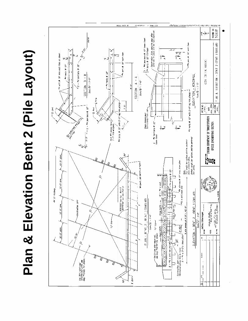
Construction Documents
General Notes
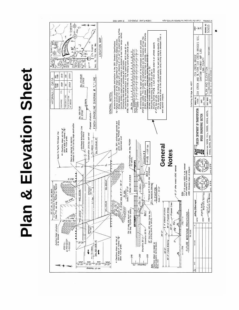
Pla
n &
Ele
vati
on
Sh
eet
Gen
eral
N
ote
s
Pla
n &
Ele
vati
on
Ben
t 2
(Pile
Lay
ou
t)
Fo
un
dat
ion
Dat
a S
hee
t

Driven Piles Section 8.1
January, 2014 24
Bent 2 – Elevation
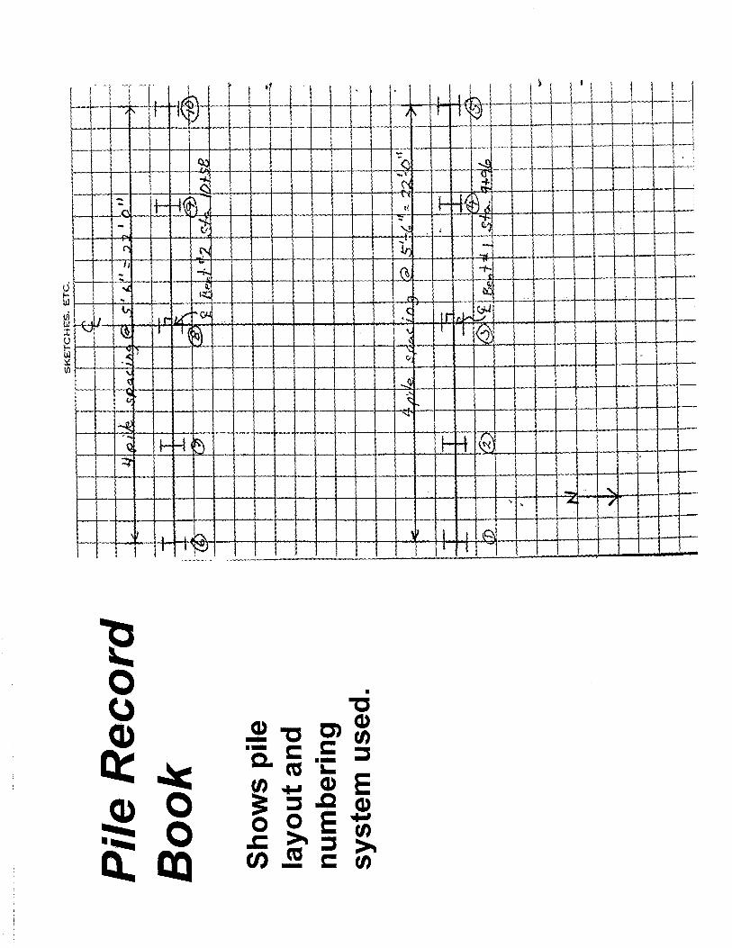
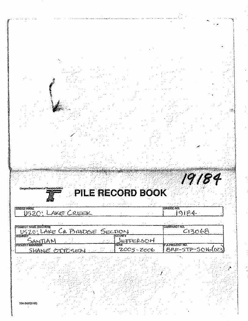
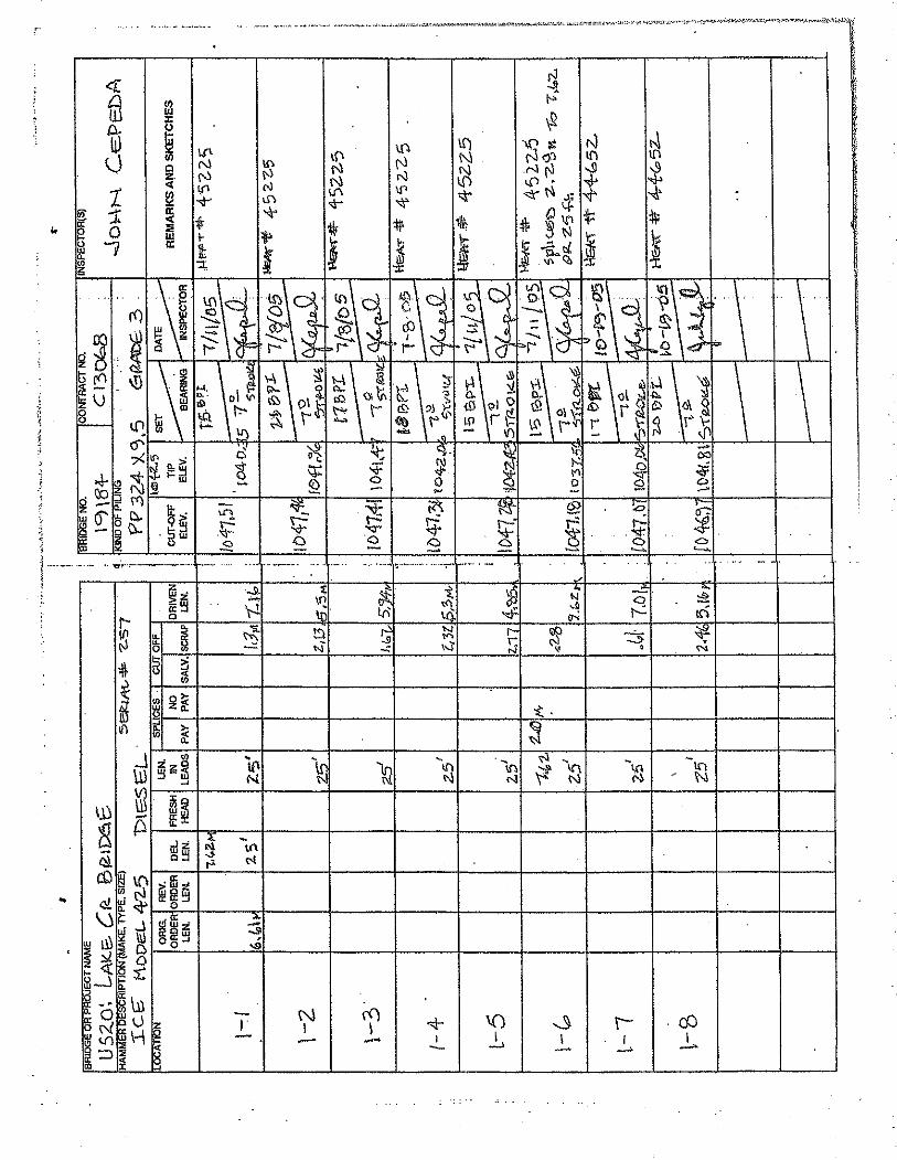
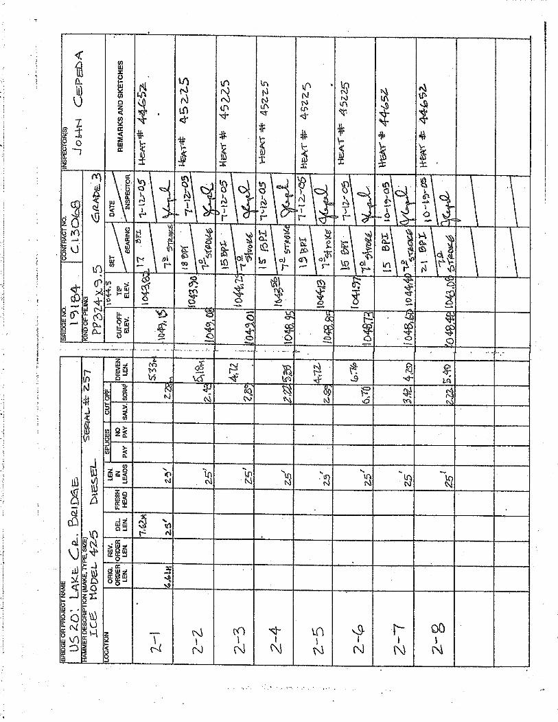
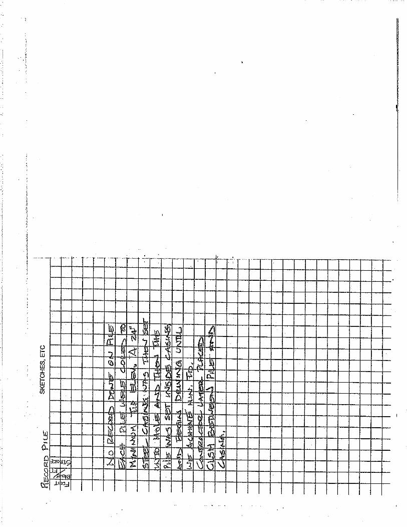
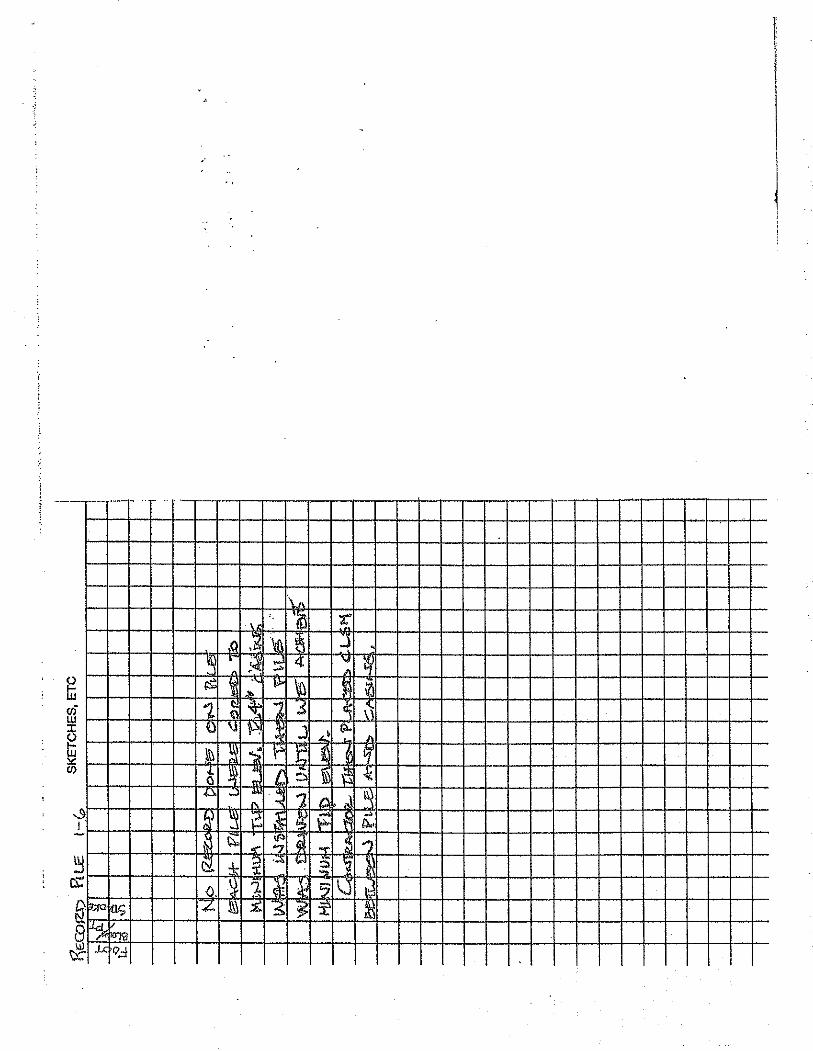
Record Keeping
• Pile Record Book
• General Daily Progress Report
• Personal Field Diary

Pile
Rec
ord
Bo
ok


Driven Piles Section 8.1
January, 2014 25
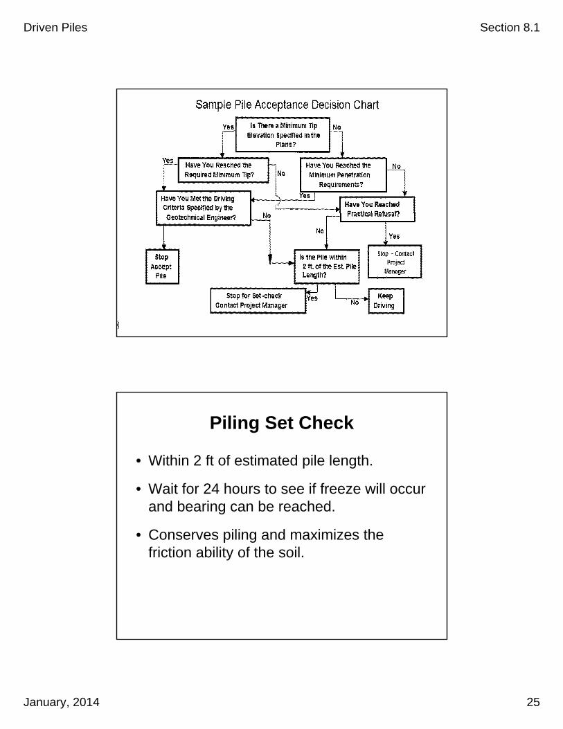
Piling Set Check
• Within 2 ft of estimated pile length.
• Wait for 24 hours to see if freeze will occur and bearing can be reached.
• Conserves piling and maximizes the friction ability of the soil.
Driven Piles Section 8.1
January, 2014 26
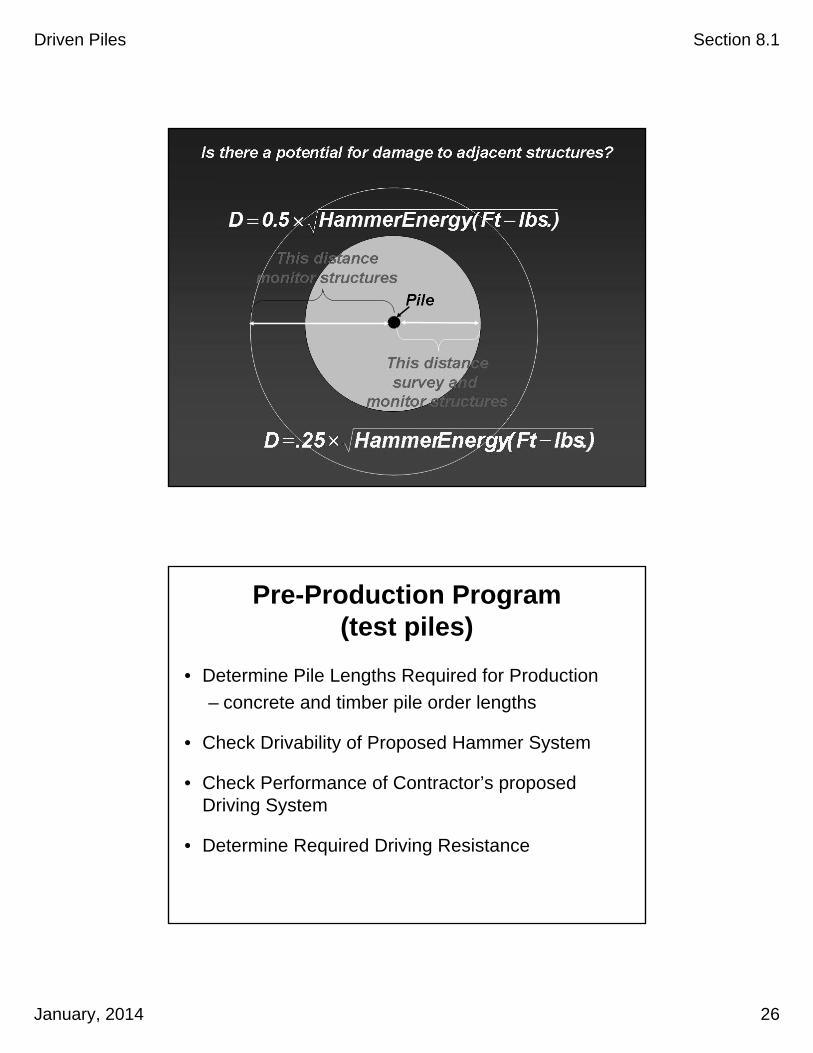
Pre-Production Program (test piles)
• Determine Pile Lengths Required for Production
– concrete and timber pile order lengths
• Check Drivability of Proposed Hammer System
• Check Performance of Contractor’s proposed Driving System
• Determine Required Driving Resistance

Driven Piles Section 8.1
January, 2014 27
Check the Driving System
• Manufacturer
• Model
• Type
• Serial Number
• Energy Rating
• Ram Weight
• Ram Stroke
Check the Driving System
Are the leads the proper type and configuration for the job?
Driven Piles Section 8.1
January, 2014 28
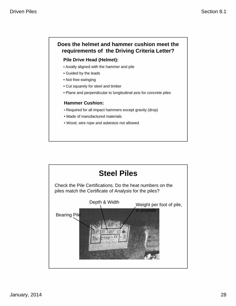
Does the helmet and hammer cushion meet therequirements of the Driving Criteria Letter?
Hammer Cushion:
• Required for all impact hammers except gravity (drop)
• Made of manufactured materials
• Wood, wire rope and asbestos not allowed
Pile Drive Head (Helmet):
• Axially aligned with the hammer and pile
• Guided by the leads
• Not free-swinging
• Cut squarely for steel and timber
• Plane and perpendicular to longitudinal axis for concrete piles
Check the Pile Certifications. Do the heat numbers on the piles match the Certificate of Analysis for the piles?
Steel Piles
Bearing Pile
Depth & Width Weight per foot of pile,in pounds
Driven Piles Section 8.1
January, 2014 29
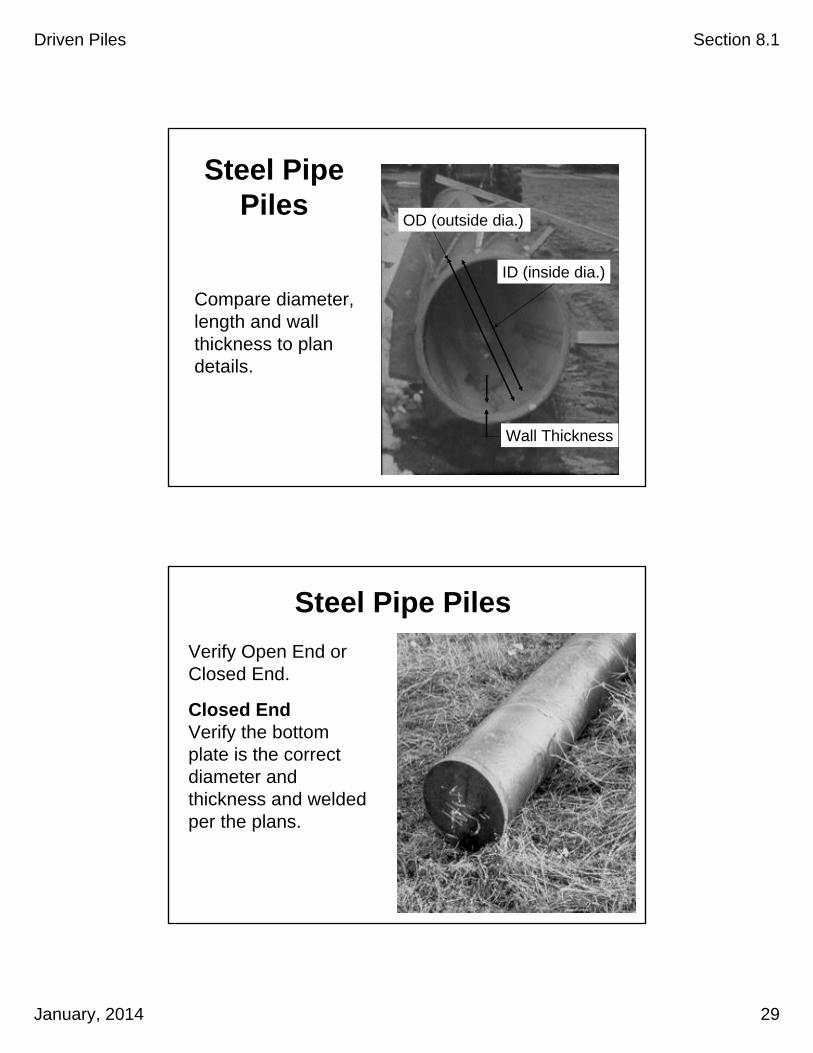
Steel Pipe Piles
Compare diameter,length and wallthickness to plandetails.
Wall Thickness
ID (inside dia.)
OD (outside dia.)
Steel Pipe Piles
Verify Open End or Closed End.
Closed EndVerify the bottom plate is the correct diameter and thickness and welded per the plans.
Driven Piles Section 8.1
January, 2014 30
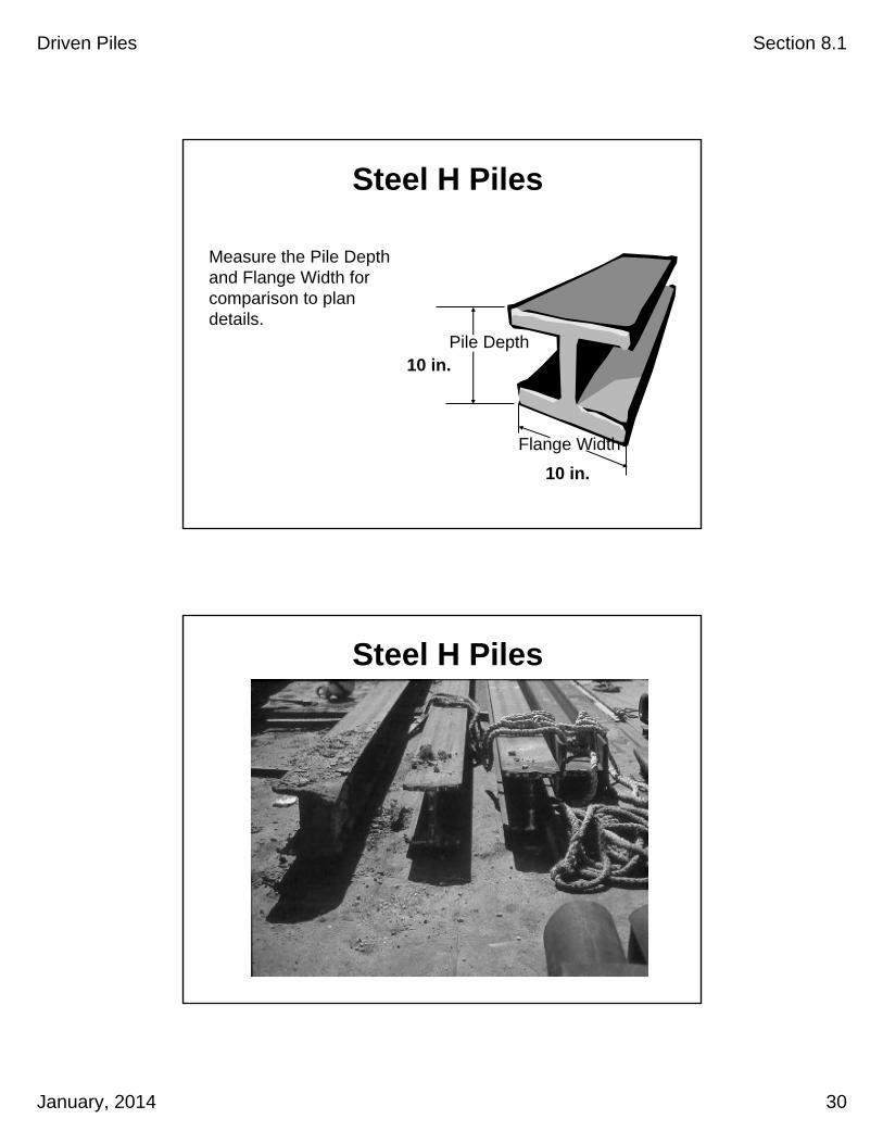
Pile Depth
Flange Width
Steel H Piles
Measure the Pile Depthand Flange Width forcomparison to plandetails.
10 in.
10 in.
Steel H Piles

Driven Piles Section 8.1
January, 2014 31
The Project Plans and Specifications detail the splicing requirements for piles. For Steel Pipe Pile a full penetration butt weld is required with a backing ring.
Pile Splices
Backing Bar (rings)
Marking Piles

Driven Piles Section 8.1
January, 2014 32
Ground SurfaceElevation= +0.00’
Reference Elevation= +2.00’
CutoffElevation = +5.00’
Length Driven is the length of pile below the cutoff elevation !
Tip Elev. = - 27.00’
5
10
15
20
25
30
35
40
45
50
5
10
15
20
25
30
35
40
45
50
5
10
15
20
25
30
35
40
45
50
Monitoring Driven Pile Lengths
Pile Marker @ 29’ penetration
Within 6 inches of Plan position
Maximum6 inches
Plan Location
Horizontal Tolerance for Driving

Driven Piles Section 8.1
January, 2014 33
Common Problems
Water in fuel
Fuel lines clogged
Fuel pump malfunctioning
Fuel injectors malfunctioning
Oil low
Oil pump malfunctioning
Water in combustion chamber
Piston rings worn
Tripping device broken
Over heating
IndicatorsHollow sound, white smoke
No smoke or little gray smoke
Inconsistent ram strokes, little gray smoke or black smoke
Inconsistent ram strokes, little gray smoke or black smoke
Blows per minute rate is lower than specified
Blows per minute rate is lower than specified
Hollow sound, white smoke
Low strokes
Pawl does not engage pistonPawl engages but doesn't lift pistonPaint and oil on cooling fins start to burn/sound changes
Common Problems – Open End Diesel
Steel Piles

Driven Piles Section 8.1
January, 2014 34
Typical causesof damage
Types ofdamage
Possible indicatorsduring driving
• Transporting and Lifting
• Low Steel Strength
• Hard Driving (Compression)
• Welding
• Splices
• Bending
• Buckling
• Accordion
• Splitting
• Pile moving out of positionduring driving
• Abrupt blow count change
• Observed pile damage near the pile head
Steel Piles
Banded to prevent “brooming”
Timber Piles

Driven Piles Section 8.1
January, 2014 35
Timber Piles
Typical causesof damage
Types ofdamage
Possible indicatorsduring driving
• Transporting
• Knots and natural defects
• Handling
• Driving
• Splintering
• Cracking
• Shearing
• Brooming(head & tip)
• Pile moving out of position during driving
• Abrupt blow count change
• Appearance
Where isthat Pile
Data Table?
Safety


Driven Piles Section 8.1
January, 2014 36

Recommended