

1
DYNAMICS OF ROTATION
AN ELEMENTARY INTRODUCTION
TO RIGID DYNAMICS
A. M. WORTHINGTON, M.A., F.R.S.
HEADMASTKR AND PKOFESSOR OP PHYSICS AT THE ROYAL
NAVAL ENGINEERING COLLEGE, DEVONPORT
THIRD EDITION, REVISED
LONGMANS, GREEN, AND CO.
39 PATERNOSTER ROW, LONDONNEW YORK AND BOMBAY
I 900

Digitized by the Internet Archive
in 2007 with funding from
IVIicrosoft Corporation
http://www.archive.org/details/dynamicsofrotatiOOwortuoft

PREFACE TO THE FIRST EDITION
Many students of Physics or Engineering, who from
want either of mathematical aptitude, or of sufficient
training in the methods of analytical solid geometry, are
unable to follow the works of mathematical writers on
Kigid Dynamics, must have felt disappointed, after master-
ing so much of the Dynamics of a Particle as is given in
the excellent and widely-used text-books of Loney, or
Garnett, or Lock, to find that they have been obliged,
after all, to stop short of the point at which their know-
ledge could be of appreciable practical use to them, and
that the explanation of any of the phenomena exhibited
by rotating or oscillating rigid bodies, so interesting and
obviously important, was still beyond their reach.
The aim of this little book is to help such students to
make the most of what they have already learnt, and to
carry their instruction to the point of practical utility.
As a matter of fact, any one who is interested and
observant in mechanical matters, and who has mastered
the relations between force, mass, and accelemtion of
velocity of translation, will find no difficulty in appre-
hending the corresponding relations between couples,
moments of inertia, and angular accelerations, in a rigid
in

iv Preface.
body rotating about a fixed axle, or in understanding the
principle of the Conservation of Angular Momentum.
Instead of following the usual course of first developing
the laws of the subject as mathematical consequences of
D'Alembert's Principle, or the extended interpretation of
Newton's Second and Third Laws of Motion, and then
appealing to the experimental phenomena for verification,
I have adopted the opposite plan, and have endeavoured,
by reference to the simplest experiments that I could
think of, to secure that the student shall at each point
gain his first ideas of the dynamical relations from the
phenomena themselves, rather than from mathematical
expressions, being myself convinced, not only that this is
the best way of bringing the subject vividly and without
vagueness before the learner, but that such a course maybe strongly defended on other grounds.
These considerations have determined the arrangement
of the chapters and the limitations of the work, which
makes no pretence at being a complete or advanced
treatise.
My best thanks are due to those friends and pupils who
have assisted me in the revision of the proof-sheets and in
the working of examples, but especially to my colleague,
Mr. W. Lardeu, for very many valuable suggestions and
corrections. A. M. W.
Devonport, Z\8t Oct. 1891.
CONTENTS.
CHAPTER I.
DEFINITIOyS OF TERMS AND PRELIMINARY KINEMATICS.
Plage 1. Rigid Body.
,, 2. Angular Velocity.
„ 2, Rate of Revolution.
,, 3. Relation between (v) and (w).
„ 3. Angular Acceleration.
„ 3. Uniformly Accelerated Rotation.
„ 5. Examples.
„ 6. Geometrical Representation of Angular Velocities and Ac-
celerations.
„ 7. On the Use of the word Moment.
„ 8. Definition of Torque.
„ 8. Definition of Equal Torques.
,, 8. Fundamental Statical Experiment.
„ 8. Measure of Torque.
„ 8. Unit Torque.
,, 9. British Absolute Unit of Torque.
„ 9. Gravitation or Engineer's British Unit of Torque.
„ 9. Distinction between * pound ' and ' lb.'
CHAPl^ER U.
BOTATION CNOKB THE INFLUMNCE OF TORQUB.
Page 11. Proposition I.
,, 12. Proposition ii.
„ 13. Methods of Experimental Verification.
a2 *

vi Contents,
Page 14. Variation of the Experiments.
„ 15. Familiar Instances.
„ 15. The Analogue of Mass in Rotational Motion.
„ 17. Rotational Inertia.
,, 17. Definition of the Unit of Rotational Inertia.
„ 18. Examples for Solution.
,, 18. To Calculate the Rotational Inertia of any Rigid Body.
„ 18. Proposition iii.
„ 19. Rotational Inertia of an Ideal Single-particle System.
„ 20. Moment of Inertia.
„ 20. Unit Moment of Inertia.
„ 21. Definition of Angular Momentum,
„ 22. To find the Kinetic Energy of a Rigid Body rotating about a
Fixed Axle.
„ 23. Work done by a Couple.
„ 23. Analogy with the Expression for the Work done by a force
in Rectilinear Motion.
,, 24. Change of Kinetic Energy due to a Couple.
„ 24. Radius of Gyration.
„ 25. Numerical Examples.
„ 30. Note to Chapter ii. D'Alembert's Principle.
CHAPTER mDEFINITIONS, AXIOMS, AND ELEMENTARY THEOREMS NECESSARY FOR
DEALING WITH MOMENTS OF INERTIA
—
ROUTH's RULE AND ITS
APPLICATION.
Page 33. Definition of Moment of Inertia of an Area.
,, 33. Definition of Moment of Inertia of a Volume.
,, 34. Axiom.
,, 34. Illustration.
„ 34. Axiom.
„ 35. Proposition iil
Contents, vii
Page 36. Routh's Rule for Finding the Moment of Inertia about an
Axis of Symmetry in certain cases.
,, 36. Examples of the Application of Dr. Routh's Rule.
,, 37. Theorem of Parallel Axes.
,, 38. Proposition iv.
„ 39. Applications.
„ 40. Proposition v.
,, 42. Examples for Solution on Chapters i., ii., and iii.
CHAPTER rv.
MATHEMATICAL PBOOFS OV THE DIFFERKNT CASES INCLUDED
UNDER route's RULE.
Page 46. To Find I for a Uniform Thin Rod about a Perpendicular
Axis through one end.
„ 47. Corollary.
„ 4S. Rectangle.
„ 48. Circular Disc.
„ 60. Thin Rod by Integration.
„ 50. Circular Disc by Integration.
„ 51. Moment of Inertia of an Ellipse.
,, 52. Sphere and Cone.
M 52. Sphere by Integration.
,, 63. Ezerdset.
CHAPTER V.
yUlETHEB PBOPOSmOMS OOMOERNUfO MOMENTS OF INERTIA—PRINCIPAL
AZM—ORAPBICAL REPRESENTATION OF INERTIA-CURVES AMD 8UR>
FAOW—IQniMOMIllTAL SYSTEMS—IltlRTU SUtLETOItl.
Page 66. Proposition Tl.
M 66. PropositioQ TIL
M 68. Proportion UL

YJji Contents,
P*ge 60. Graphical Construction of Inertia-Curves and Surfaces.
„ 62. Diagrams of Inertia Curves.
63, Construction of Moment of Inertia Surface.
„ 64. EquimomenUl Systems—Proposition X.
„ 64. Inertia Skeleton—Proposition xi.
CHAPTER VI.
SIUFLB HARMONIC MOTION.
Page 67. Definition of Simple Harmonic Motion.
„ 68. Definition of Period.
„ 69. Definition of Phase.
69. Expression for the Period or Time of a Complete Oscillation.
CHAPTER Vn.
AH BLEMKNTABT ACCOUNT OF THB CIECUMSTANCES AND LAWS OF
ELASTIC OSCILLATIONS.
Page 70. Perfect or Simple Elasticity.
„ 70. Hooke's Law.
„ 71. Illustrations of Hooke's Law.
„ 72. Oscillations due to Elasticity.
73. Ratio of Acceleration to Displacement.
73. Expression for the Time of a Complete Oscillation.
„ 74. Applications.
„ 75. Extension to Angular Oscillations.
,, 76. Applications.
„ 76. Equivalent Simple Pendulum.
„ 77. Examples.
79. Oscillating Table for Finding Moments of Inertia.
„ 81. Examples for Solution.

Contents. ix
CHAPTER vni.
CONSERVATION OP ANGULAR MOMENTUM.
Page 82. Analogue in Rotation to Newton's Third Law of Motion.
„ 83. Application of the Principle in cases of Motion round a fixed
Axle.
„ 83. First Example.
„ 84. Second Example.
„ 85. Third Example.
„ 85. Fourth Example.
„ 87. Consideration of the Kinetic Energy.
„ 87. Other Exemplifications of the Principle of the Conservation
of Angular Momentum.
,, 88. Graphical representation of Angular Momentum.
„ 89. Moment of Momentum.
,» 89. Conservation of Moment of Momentum.
„ 91. General Conclusion.
„ 91. Caution.
,, 91. Ballistic Pendulum.
„ 9& Examples.
CHAPTER IX.
ON TBS KINXMATICAL AND DYNAMICAL PROPERTIES OF TBI
CENTRE OF MASS.
Page 94. Evidence of the Existence for a Rigid body of a point pos-
sessing peculiar Dynamical Relatious.
M 95. ExperimenU (1), (2), and (3).
„ 96. Experiments (4) and (5).
M 96. A Couple causes Rotation about an Axis through the Centre
of Gravity.
M 97. Experiment (6) with a Floating Magnet
,. 98. Experiment (7).

Contents.
Pago 99. Definition of Centre of Mass.
,, 100. Proposition i.—(Kinematical.) On the Displacement of the
Centre of Mass.
,, 101. Pure Rotation and Translation.
,, 101. Proposition ii. — (Kinematical.) On the Velocity of the
Centre of Mass.
„ 101. Proposition iii.—(Kinematical.) On che Acceleration of the
Centre of Mass.
,, 102. Summary.
„ 102. Corresponding Propositions about Moments.
„ 103. Proposition iv. On the Resultant Moment of the Mass-
Accelerations about any Axis.
,, 104. Proposition v. On the Motion of the Centre of Mass of a
body under External Forces.
„ 105. Proposition vi. On the Application of a Couple to a Free
Rigid Body at Rest.
,, 105. Proposition VII. The Motion of the Centre of Mass does not
affect Rotation about it.
„ 106. Independent treatment of Rotation and Translation.
„ 106. On the Direction of the Axis through the Centre of Mass
about which a Couple causes a free Rigid Body to turn.
Caution.
,, 107. Total Kinetic Energy of a Rigid Body.
,, 108. Examples.
,, 110. Examples for Solution.
CHAPTER X.
CENTRIPETAL AND CENTRIFUGAL FORCES.
Page 111. Consideration of the Forces on the Axle.
,, 111. Proposition. Uniform Motion of a Particle in a Circle.
,, 112. Use of the terms * Centripetal Force' and 'Centrifugal
Force.'
,, 113. Centripetal Forces in a Rotating Rigid Body.
,, 113. Rigid Lamina.

Co7ttents xi
Page 115. Extension to Solids of a certain type.
,, 116. Convenient Dynamical Artifice.
„ 117. Centrifugal Couples.
„ 118. Centrifugal Couple in a body of any shape.
„ 119. Centrifugal Couples vanish when the Rotation ia about a
Principal Axis.
„ 121. Importance of Properly Shaping the Parts of Machinery
intended to Rotate rapidly.
,, 121. Equimomental Bodies similarly rotating have ecjual and
similar Centrifugal Couples.
,, 121. Substitution of the 3-rod Inertia-Skeleton.
„ 123. Transfer of Energy under the action of Centrifugal Couples
CHAPTER XL
OBNTBE or PEBCUSSION.
Page 125. Thin Uniform Rod.
„ 126. Experiment.
„ 127. Experiment.
,, 128. Illustrations—Cricket Bat, Door.
„ 128. Centre of Percussion in a Body of any Form.
CHAPTER Xn.
miMATION or THE TOTAL AMQULAB MOKIimJll.
Page 130. Simple Illustrations.
„ 132. Additional Property of Principal Axat.
M 133. Total Angular Momentum.
„ 133. The CentripeUl Couple.
„ 135. Rotation under the influence of no Torque. The Invariable
xii Contents.
CHAPTER XIII.
ON SpMB OF THE PHENOMENA PRESENTED BY SPINNING BODIES.
Page 136. Gyroscope.
137. Experiments (1), (2), and (3).
138. Experiment (4).
139. Definition of Precession.
139. Experiment (5).
140. Experiments (6), (7), and (8).
141. Experiments (9) and (10).
141. Precession in Hoops, Tops, etc.
142. Further Experiment with a Hoop.
143. Bicycle.
143. Explanation of Precession.
145. Analogy between Steady Precession and Uniform Motion in
a Circle.
145. Calculation of the Rate of Precession.
148. Observation of the 'Wabble.' '
150. Explanation of the Starting of Precession.
152. Gyroscope with Axle of Spin Inclined.
153. Influence of the Centrifugal Couple.
154. Explanation of the effects of impeding or hurrying Pre-
cession.
154. The Rising of a Spinning Top.
156. Calculation of the « Effort to Precess.*
157. Example (1) Precessional Forces due to the wheels of a rail-
way-engine rounding a curve.
167. Precessional Stresses on the machinery of a pitching, rolling,
or turning ship.
158. Example (2) Torpedo-boat turning.
159. Appendix. Evaluation of the steady precessional velocity
of a gyroscope or top with the axis of spin inclined.
DYNAMICS OF ROTATION.
CHAPTER 1.
DEFINITIONS OF TERMS AND PKELIMINARY KINEMATICS.
Rigid Body.—A body in Dynamics is said to bo rigid
(i.e. stifT) so long as the forces acting upon it do not change
the relative positions of its parts.
We shall deal, at first, chiefly with such familiar rigid bodies
as a fly-wheel turning on its axle ; a cylindrical shaft ; a grind-
stone ; a door turning on its hinges ; a pendulum ; a magnetic
compass-needle ; the needle of a galvanometer \vith its
attached mirror.
It should be observed that such a body as, for example, a
wheelbarrow being wheeled along a road is not, taken as a
whole, a rigid body, for any point on the circumference of the
wheel changes its position with respect to the rest of the
barrow. The wheelbarrow consists, in fact, of two practically
rigid bodies, the wheel and the barrow.
On the other hand, a sailing-boat may be regarded as a rigid
body so long as its sails are taut under the influence of the
wind, even though they be made of a material that is far
from rigid when otherwise handled.
So also a stone whirled by an inextcnsible string constt-
totes, with the string, a single body which may be regarded
OS rigid so long as the string is straight

Dynamics ofRotation,
Angular Velocity.—When a rigid body turns about a
fixed axis, every particle of the body describes a circle about
this axis in the same time. If we conceive a radius to be
drawn from the centre of any such circular path to the
particle describing it, then, if the rotation be uniform, the
number of unit angles swept over in unit time by such a
radius is called the angular velocity of the body.
The unit of time invariably chosen is the second, and the
unit angle is the * radian,' ix. the angle of which the arc is
equal to the radius.
Hence, in brief, we may write
Angular velocity (when uniform) = Number of radians
described per second.
The usual symbol for the angular velocity is w (the Greek
omega).
When the angular velocity is not uniform, but varies, then
its value at any instant is the number of radians that would
be swept out per second if the rate of turning at that instant
remained uniform for a second.
Rate of Revolution.—Since in one revolution the radius
describes 27r radians, it follows that the number of revolutions
made per second when the angular velocity is w, is —, and
that when a body makes one revolution per second, it
describes 27r unit angles per sec, and has therefore an
angular velocity = w = 27r.
Thus a body which makes 20 turns a minute has an angular
1 .^ 20x27r 27rvelocity- -= -3-.
Tangential Speed.—The linear velocity {v) of a particle

Defiyiitions of Terms,
describing a circle of radius r about a fixed axis is at any
instant in the direction of the tangent to the circular path,
and is conveniently referred to as the tangential speed.
Relation between v and w.—Since an angular velocity
w radians per sec. corresponds to a travel of the particle over
an arc of length rw each second, it follows that
« = ra»
or cu = —
.
r
Very frequent use will be made of this relation.
Examples.—(1) A rotating drum 4 feet in diameter is driven by a
strap which travels 600 feet a minute and without slipping on the
druuL To find the angular velocity
—
• — = 60 = 6 radians per sec.
2
(t) A wheel 3 feet in diameter has an angular velocity of 10. Find
the speed of a point on its circumference.
»=r«= r5 X 10 feet per seo.
"15 feet per sec.
Angular Acceleration.—When the rate of rotation of a
rigid body about a fixed axle varies, then the rate of change
of the angular velocity is called the angular acceleration, just
as rate of change of linear velocity is called linear acceleration.
The usual symbol for angular acceleration is ». Thus » is
at any instant the number of radians per second that are being
added per second at the instant under consideration. We shall
deal at first with uniform angular accelerations, for which wehall use the less genera] symbol A.
Uniformly accelerated Rotation.—If a rigid body

Dynamics of Rotation,
start rotating from rest with a uniform angular acceleration
A, then after i seconds the angular velocity w is given by
0) = A/.
If the body, instead of being at rest, had initially an angular
velocity w^, then at the end of the interval of t seconds the
angular velocity would be
a> = (!)„+A^ . . . . . (i)
Since during the t seconds the velocity has grown at a
uniform rate, it follows^ that its average value during the
interval, which, when multiplied by the time, will give the
whole angle described, lies midway between, or is the arith-
metic mean between, the initial and final values, %,e. the
average angular velocity for the interval,
2
= co,+ JA^,
and the angle described
= (a,„+JAO^
=^.i^W (ii)
By substituting in (ii) the value of i given in (i) we obtain
the equation
a>2=u>^2_|.2A6> (iii),
which connects the angular velocity w with initial velocity w,
and the angle Q swept through.
The student will observe that these equations are precisely
similar to and are derived in precisely the same way as the
tki'ee fundamental kinematic equations that he has learned to
^ It is not considered necessary to reproduce here the geometrical
or other reasoning by which this is established. See Garnett's
JElementarj/ DynamicB, and Lock's Dynamicsfor Beginners.

Definitions of Terins. 5
use in dealing with uniformly accelerated rectilinear motion
of a particle, viz.:
—
v=-u-\-at (i)
s=u/-f ia/» (ii)
t;*=u'+ 2a5 (iii)
Example 1.—A wheel is set gradually rotating from rest with
a uniform angular acceleration of 30 units ofangular velocity per sec.
In what time will it acquire a rate of rotation of 300 revolutions per
minute 1
iSo/ution.—300 revolutions per minute is an angular velocity of
—^^r— radians per sec, which will be attained m -—— sec.
=!r8ec.= ?iil? sec.= 1-0472 sec.3 3
Example 2.—A wheel revolves 30 times per sec. : with what uni-
form angular acceleration will it come to rest in 12 sec., and howmany turns will it make in coming to rest ?
SoLxAvm.—Initial angular velocity = «.= 30 x 2*r = 60»r.
This is destroyed in 12 sec.,
GOrr.*. aogolar accelerations --r^
I2
s= — 6tr
S3 -16 708 radians per sec., each second.
The — sign means that the direction of the acceleration is opposite
to that of the initial velocity «,, which we have tacitly assumed to
be + in writing it equal to 60»r.
The angle described in coming to rest is obtained at once from the
drd of the ftudamental equations now that we know the value of A.
Thus:—«>-«.> + 2A^0«-(e0fr)«-10irtf
.'. 10ird-(60ir)«
/. d-300ir
i*3G0ir revolutions.
Sir
ilSO revolutions.
Dynamics of Rotation.
Example 3.—A wheel rotating 3000 times a minute has a uniform
angular retardation of tt radians per sec. each second. Find when it
will be brought to rest, and when it will be rotating at the same
rate in the opposite direction.
3000 revolutions per min. = SOOOxStt
60 '-:
= IOOtt radians per sec, *^*^
and will therefore be destroyed by the opposing acceleration tt in 100
sec. The wheel will then be at rest, and in 100 sec. more the same
angular velocity will have been generated in the opposite direction.
(Compare this example with that of a stone thrown verticallj'' upand then returning.)
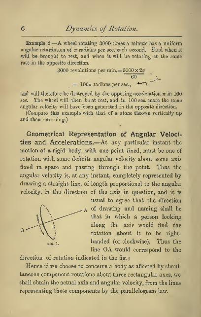
Geometrical Representation of Angular Veloci-
ties and Accelerations.—At any particular instant the
motion of a rigid body, with one point fixed, must be one of
rotation with some definite angular velocity about some axis
fixed in space and passing through the point. Thus the
angular velocity is, at any instant, completely represented by
drawing a straight line, of length proportional to the angular
velocity, in the direction of the axis in question, and it is
usual to agree that the direction
of drawing and naming shall be
that in which a person looking
along the axis would find the
rotation about it to be right-
y,^i/ handed (or clockwise). Thus the
line OA would correspond to the
direction of rotation indicated in the fig. /
Hence if we choose to conceive a body as affected by simul-
taneous component rotations about three rectangular axes, wo
shall obtain the actual axis and angular velocity, from the lines
representing these components by the parallelogram law.
Definitions of Terms,
In the same way angular acceleration about any axis fixed
in space may be represented by drawing a line in its direc-
tion (with the same convention), and simultaneous angular
accelerations may be combined according to the parallelo-
gram law.
On the Use of the word Moment.—The word moment
was first used in Mechanics in its now rather old-fashioned
sense of * importance ' or * consequence/ and the moment of a
force about an axis meant the importance of the force with
respect to its power to generate in matter rotation about the
axis ; and again, the moment of inertia of a body with respect
to an axis is a phrase invented to express the importance of
the inertia of the body when we endeavour to turn it about
the axia When we say that the moment of a force about an
axis varies as the force, and as the distance of its line of action
from the axis, we are not so much defining the phrase
* moment of a force,' as expressing the result of experiments
made with a view to ascertaining the circumstances under
which forces are equivalent to each other as regards their
turning power. It is important that the student should bear
in mind this original meaning of the word, so that such
phrases as * moment of a force ' and * moment of inertia ' mayat once call up an idea instead of merely a quantity.
But the word ' moment ' has also come to bo used by analogy
in a purely technical sense, in such expressions as the ' mo-
ment of a mass about an axis,' or ' the moment of an area with
respect to a plane,' which require definition in each case. In
these instances there is not always any corresponding physical
idea, and such phrases stand, both historically and scientifi-
cally, on a difierent footing.

8 Dyna77iics of Rotation.
Uufortunately the words ' moment of a force are regarded
by some writers as the name rather of the product * force Xdistance from axis ' than of the property of which this product
is found by experiment to be a suitable measure. But
happily for the learner the difficulty thus created has been
met by the invention of the modern word torque to express
' turning power.'
Definition ofTorque.—A force or system of forces which
has the property of turning a body about any axis is said to
be or to have a torque about that axis (from the Latin torqueo,
I twist).
Definition of Equal Torques.—Two torques are said to
be equal when each may be statically balanced by the same
torque.
Fundamental Statical Experiment.—Torques are
found to be equal when the products of the force and the
distance of its line of action from the axis are equal. Experi-
ments in proof of this may be made with extreme accuracy.
The result may also be deduced from Newton's Laws of
Motion.
Measure of Torque.—The value of a torque is the value
of this product. This again is a matter of definition.
Unit Torque. —Thus the unit force acting at unit distance
is said to be or to have unit torque, and a couple has unit
torque about any point in its plane when the product of its
arm and one of the equal forces is unity.

Defifiilions of Terms.
British Absolute Unit of Torque.—Siuce in the British
absolute system, in which the pound is chosen as the unit of
mass, the foot as unit of length, and the second as unit of
time, the unit of force is the poundal, it is reasonable and is
agreed that the British absolute unit of torque shall be that
of a poundal acting at a distance of 1 foot, or (what is the
same thing, as regards turning) a couple of which the force is
one poundal and the arm one foot. This we shall call a
poundal-foot, thereby distinguishing it from the foot-poundal,
which is the British absolute unit of work.
Gravitation or Engineer's British Unit of Torque.
—In the Gravitation or Engineer's system in this country,
which starts with the foot and second as units of length and
time, and the pound pull as unit of force, and with g lbs.*
as unit of mass, the unit of torque is that of a couple of which
each force is 1 pound and the arm 1 foot. This may be called
the * pound-foot.'
Distinction between * pound ' and * lb.'—The student
should always bear in mind tliat the word pound is used in
two senses, sometimes as a force, sometimes as a mass. He
will find that it will contribute greatly to clearness to follow
the practice adopted in this book, and to write the uord
* pound ' whenever a force is meant, and to use the symbol
'lb.' when a mass is meant.
Axis and Axle.—An axis whose position is fixed rela-
tively to the particles of a Ixxly may be conveniently referred
to as an axU.
* It !• ooDvenient to give a name to this practical unit of inertia, or
•laggiahneea. of about 32-2 Ibt. We ihall call it a ' elug.'

CHAPTEE II.
ROTATION UNDER THE INFLUENCE OF TORQUE.
The student will have learnt in that part of Dynamics which
deals with the rectilinear motion of matter under the influ-
ence of force, and with which he is assumed to be familiar,
that the fundamental laws of the subject are expressed in the
three statements known as Newton's Laws of Motion. These
propositions are the expression of experimental facts. Thus,
nothing but observation or experience could tell us that the
acceleration which a certain force produces in a given mass
would be independent of the velocity with which the mass
was already moving, or that it was not more difficult to set
matter in motion in one direction in space than in another.
We shall now point out that in the study of the rotational
motion of a rigid body we have exactly analogous laws and
properties to deal with : only that instead of dealing with
forces we have torques ; instead of rectilinear velocities and
accelerations we have angular velocities and accelerations
;
and instead of the simple inertia of the body we have to con-
sider the importance or moment of that inertia about the
axis, which importance or moment we shall learn how to
measure.
It will contribute to clearness to enunciate these corre-
sponding laws with reference first to a rigid body pivoted
10
Rotation under the Injliience of Torqtie. 1
1
about a fixed axle, i.t. an axis which remains fixed in the body,
and in its position in space ; and although it is possible to
deduce each of the propositions that will be enunciated as con-
sequences of Newton's Laws of Motion, without any further
appeal to experiment, yet we shall reserve such deduction
till later, and present the facts as capable, in this limited case
at any rate, of fairly exact, direct experimental verification.
Proposition \.—Tht rait of rotation of a rigid body revolving
ahcui an axis fixed in the body and in space cannot be changed
except by the application of an external force having a momcjit
about the axis, i.e. by an external torque.
Thus, a wheel capable of rotating about a fixed axle cannot
begin rotating of itself, but if once set rotating would con-
tinue to rotate for ever with the same angular velocity, unless
acted on by some external torque (due, e.g. to friction) hav-
ing a moment about the axis. Any force whose line of action
passes through the axis will, since this is fixed, be balanced
by the equal and opposite pressure which fixes the axis. It
is true that pressure of a rotating wheel against the material
axle or shaft about which it revolves does tend to diminish
the rate of rotation, but only indirectly by evoking friction
which has a moment about the axis.
It is impossible in practice to avoid loss of rotation through
the action of friction both with the bearings on which the
body is pivoted and with the air ; but since the rotation is
always the more prolonged and uniform the more this friction
is diminished, it is impossible to avoid the inference that the
motion would continue unaltered for an indefinite period
could the friction bo entirely removed.
The student will i>erccive the analogy between this first

1
2
Dynamics of Rotation,
Proposition and that known as Newton's First Law of
Motion.
Proposition II.—The angular acceleration or rate of clmnge
of angular velocity produced in any given rigid mass rotating about
an axis fixed in the body and in space is proportional to the
moment about the axis of the external forces applied, i.e. to the
value of the external torque.
To fix the ideas, let the student
think first of a wheel rotating about
a fixed shaft passing through its
O1
centre, and to this wheel let us
apply a constant torque by pulling
with constant force the cord AB^^°* ^'
wrapped round the circumference.
[It may be well to point out here that if the wheel be accu-
rately symmetrical, so that its centre of gravity lies in the
axis of the shaft, then, as will be shown in the chapter on
the Centre of Mass, since the
centre of gravity or centre of
mass of the wheel does not
move, there must be some other
equal and opposite external
force acting on the body. This
i^^TX^ other force is the pressure of the
axle, so that we are really apply-
ing a couple as in Fig. 2 ; but this latter force has no moment
about the axis, and does not directly afi'ect the rotation.]
Our Proposition asserts that
(1) So long as the torque has the same value, i.e. so long
as the cord is pulled with the same force, the

Rotation under the Influence of Torque. 1
3
acceleration of the angular velocity of the wheel
is uniform, so that the effect on the wheel of any
torque, in adding or subtracting angular velocity, is
independent of the rate at which the wheel may
happen to be rotating when the torque is applied.
(2) That a torque of double or treble the value would pro-
duce double or treble the acceleration, and so on.
(3) If several torques be applied simultaneously, the effect
of each on the rotation is precisely the same as if it
acted alone.
Also it follows
(4) That different torques may be compared, not only
statically but also dynamically, by allowing them
to act in turn on the same
pivoted rigid body in a
plane perpendicular to the
axis, and observing the
angular velocity that each
generates or destroys in
the same time.
Methods of ExperimentalVerification.—Let an arrangement
equivalent to that of the figure be
made. AB is an accurately centred
wheel turning with as little friction
as possible on a horizontal ax in, e.Q.
a bicycle wheel on ball bearings.
Round its circumference is wrapped a fine cord, from one
end of which hangs a mass of known weight (W), which
descends in front of a gradaated scale.
no. 4.

14 Dynamics of Rotation,
It will be observed that C descends with uniform accelera-
tion. This proves that the tension (T) of the cord BC on
the weight is uniform, and from observation of the value
(a) of the acceleration, that of the tension is easily found,
being given by the relation
W-T_aW -g
(where <7 is the acceleration that would be produced in the mass
by the force W alone), and T multiplied by the radius of the
wheel is the measure of the torque exerted. Thus the arrange-
ment enables us to apply a known and constant torque.
But since the linear acceleration of C is uniform, it follows
that the angular acceleration of the wheel is uniform.
By varying the weight W, the torque may be varied, and
other torques may be applied simultaneously by means of
weights hung over the axle, or over a drum attached thereto,
and thus the proportionality of angular acceleration to total
resultant torque tested under various conditions.
It will be observed that in the experiments described we
assume the truth of Newton's Second Law of Motion in order
to determine the value of the tension (T) of the cord ; but it
is possible to determine this directly by inserting between Cand B a light spring, whose elongation during the descent
tells us the tension applied without any such assumption.
Variation of the Experiments.—Instead of using our
known torque to generate angular velocity from rest, we may
employ it to destroy angular velocity already existing in
the following manner :
—
Let a massive fly-wheel or disc be set rotating about an
axis with a given angular velocity, and be brought to rest by

Rotation under the Influence of Torque, 1
5
a friction brake which may bo easily controlled so as to
maintain a constant measurable retarding torque. It will be
found that, however fast or slowly the wheel be rotating, the
same amount of angular velocity is destroyed in the same
time by the same retarding torque ; that a torque r times as
great destroys the same amount of angular velocity in —
of the time; while if a second brake be applied simultaneously
the effect of its retarding couple is simply superadded to that
of the first.
It may be remarked that the direct experimental verifica-
tions here quoted can be performed with probably greater
accuracy than any equally direct experiment on ihai part of
Newton's Second Latv of Motion to which our 2nd Proposition
corresponds^ viz. that ' the linear acceleration of a given body is
proportional to the impressed force, and takes place in the
direction of the force.'
Thus, our second Proposition for rotational motion is really
less far removed than is Newton's Second Law of Motion
from fundamental experiment
Familiar Instances.—Most people are quite familiar with
immediate consequences of these principles. For example, in
order to close a door every one takes care to apply pressure
near the outer and not near the hinged side, so as to secure
a greater moment for the force. A workman checking the
rotation of any small wheel by friction of the hand applies
hi« hand near the circumference, not near the axis.
The Analogue of Mass in Rotational Motion.—Inthe study of rectilinear motion it is found that if after making
oxperimonts on some given body we pass to another, the

Dynamics of Rotation.
same forces applied to the second body do not, in general,
produce in it the same accelerations. The second body is
found to be less easy or more easy to accelerate than the
first. We express this fact by saying that the 'inertia' or
* mass ' of the second body is greater or less than that of the
first. Exactly the same thing occurs in the case of rotational
motion, for experiment shows that the same torque applied
to different rigid bodies for the same time produces, in
general, different changes of angular velocity. Thus, the
pull of a cord wrapped round the axle of a massive fly-wheel
will, in say 10 seconds, produce only a very slow rotation,
while the same torque applied to a smaller and lighter wheel
will, in the same time, communicate a much greater angular
velocity.
It is found, however, that the time required for a given
torque to produce a given angular velocity does not depend
simply on the mass of the rigid body. For, if the wheel be
provided as in the figure with heavy
bosses, and these be moved further
from the axis, then, although the
mass or inertia of the wheel, as re-
gards bodily motion of the whole in
a straight line, is unaltered, yet it is
now found to be more difficult to
accelerate rotationally than before.
The experiment may be easily made
with our bicycle wheel of Fig. 4, by removing alternate
tensional spokes and fitting it with others to which sliding
masses can be conveniently attached.
With two wheels, however, or other rigid bodies, precisely
similar in all respects except that one is made of a lighter
FIO. 5.

Rotatio7i icnciei' the Inflttence of Torque. 17
material than the other^ so that the masses are different, it is
found that the one of less mass is proportionately more easy
to accelerate rotationally.
Hence we perceive that in studying rotational motion we
have to deal not only with the quantity of matter in the
body, but also with the arrangement of this matter about the
axis ; not solely with the mass or inertia of the body, but
with the importance or moment of this inertia with respect
to the axis in question. We shall speak of this for the
present as the Rotational Inertia of the body, meaning that
property of the body which determines the time required for
a given torque to create or destroy in the body a given
amount of rotational velocity about the axis in question.
Definition of the Unit of Rotational Inertia.—Just
as in the Dynamics of rectilinear motion we agree that a body
shall be said to have unit mass when unit force acting on it
produces unit acceleration, so in dealing with the rotation of
a rigid body it is agreed to say that the body has unit rota-
tional inertia about the axis in question when unit torque
gives it unit angular acceleration, i.e. adds or destroys in it,
in one second, an angular velocity of one radian per sec.
If unit torque acting on the body takes, not one second,
])Ut two, to generate the unit angular velocity, then we say
that the rotational inertia of the body is two units, and,
speaking generally, the relation between the torque which
acts, the rotational inertia of the body acted on, and the
angular acceleration produced, is given by the equation
Angular acceleration==—Torque
Rotational inertia
Just as in rectilinear motion, the impressed force, the
B

1
8
Dynamics of Rotation.
acted on, and the linear acceleration produced, are connected
by the relation
Acceleration= .
mass
Examples for Solution.— (1) A friction bralce which exerts a con-
stant friction of 200 pounds at a distance of 9 inches from the axis of
a fly-wheel rotating 90 times a minute brings it to rest in 30 seconds.
Compare the rotational inertia of this wheel with one whose rate of
rotation is reduced from 100 to 70 turns per minute by a friction
couple of 80 pound-foot units in 18 seconds. Ans. 25 : 24.
(2) A cord is wrapped round the axle, 8 inches in diameter, of a
massive wheel, whose rotational inertia is 200 units, and is pulled
with a constant force of 20 units for 15 seconds, when it comes off.
What will then be the rate of revolution of the wheel in turns
per minute? The unit of length being 1 foot, and of time 1
second. Ans. 4*774 turns per minute.
To calculate the Rotational Inertia of any rigid
body.—We shall now show how the rotational inertia of any
rigid body may be calculated when the arrangement of its
particles is known.
We premise first the following :
—
Proposition III.—The '•rotational inertia' of any rigid body
is the sum of the * rotational inertias ' of its constituent parts.
That this is true may be accurately ascertained by trials
with the experimental wheel of Figs. 4 and 5. Let the wheel,
unloaded by any sliding pieces, have its rotational inertia
determined by experiment with a known torque in the manner
already indicated, and call its value I„. Then let sliding
pieces be attached in certain noticed positions, and let the
new value of the rotational inertia be I,. Then, according
to our proposition, Ii — 1„ is the rotational inertia of the sliders.
If this be the case, then the increase of rotational inertia

Rotation under the Injlnence of Torqtte, 1
9
produced by the sliders in this position should be the same,
whether the wheel be previously loaded or not. If trial be now
made with the wheel loaded in all sorts of ways, it will be
found that this is the case. The addition of the sliders in the
noticed positions always contributes the same increase to the
rotational inertia.
Rotational Inertia of an ideal Single-particle
System.—We now proceed to consider theoretically, in the
light of our knowledge of the dynamics of a particle, what
must be the rotational inertia of an ideal rigid system
consisting of a single particle of mass m connected by a
rigid bar, whose mass may be neglected, to an axis at dis-
tance (r).
Let be the axis, M the particle, so that OM=r, and
let the system be acted on
by a torque of L units. Y^^
This we may suppose to bo 2 ^^ 1^
due to a force P acting on the
particle itself, and always at right angles to the rod OM, and
of such value that the moment of P is equal to the torque,
ie. Pr=L or P= -.r
The force P acting on the mass m generates in it a linear
P Pacceleration a « — in its own direction. — is therefore the
w mamount of linear speed generated per unit time by the force
in its own direction, and whatever be the variations in this
linear speed (v), - is alwajrs equal to the angular velocity w,
and therefore the amount of angular velocity generated per
20 Dymainics of Rotation.
unit time, or the angular acceleration, A, is - th of the linear
speed generated in the same time,
i.e. A= P Pr
rm mr^
j_L
:
mr
Torque""
'-
mr'•
TorqueBut A= :^'Y7 =-
;(See p. 17.)
rotational inertia
.-. The rotational inertia of a single particle of mass m at a
distance r from the axis=m7-^.
Any rigid body may be regarded as made up of such ideal
single-particle systems, and since the rotational inertia of the
whole is the sum of the rotational inertias of the parts, we
see that if mi, 7?22, ^s, ... be the masses of the respective
particles, ri, r^, i\y . . . their distances from the axis, then
The rotational inertia of the body
=^'ni{rj^ -^m^r^^ -\-mzi\^ -{- ...
This quantity 2(???r') is generally called the Moment of
Inertia of the body. The student will now understand at
once why such a name should be given to it, and the name
should always remind him of the experimental properties to
which it refers.
We shall from this point onward drop the term* * rotational
inertia,' and use instead the more usual term 'moment of
inertia/ for which the customary symbol is the letter I.
Unit Moment of Inertia.—We now see that a particle

Rotation tnider the Influence of Torque. 2 1
of unit mass at unit distance from the axis has unit moment
of inertia.
It is evi(\ent also that a thin
circular hoop of unit radius
and of unit mass rotating
about a central axis perpen-
dicular to the plane of the
circle, has also unit moment. ,
FIG. 7. no. 8.
of inertia; for every particle
may with close approximation be regarded as at unit dis-
tance from the centre.
In fact, I=2(7nr')
=2(mxl*)
=2(m)
= 1.
The same is true for any segment of a thin hoop (Fig. 8)
of unit radius and unit mass, and it is also true for any thin
hollow cylinder of unit radius and unit mass, rotating about
its own axis.
Thus the student will find it an easy matter to prepare
accurate standards of unit moment of inertia. A thin
cylinder or hoop, of one foot radius and weighing 1 lb., will
have the unit moment of inertia on the British absolute
system. We shall call this the Ib.-foot^ unit. The engineer's
unit is that of one slug (or 32 2 lbs.) at the distance of 1 foot,
Le. a slug-foot^.
Definition of Angular Momentum.—Just as the pro-
duct mass X velocity, or (mr), in translational motion is called
momentum, so by analogy when a rigid body rotates about a
fixed axle, the product (moment of inertia) x (angular velocity),

22 Dynamics of Rotation,
or (lo)), is called angular momentum.* And just as a force is
measured by the change of momentum it produces in unit
time, so a torque about any axis is measured by the change
of angular momentum it produces in unit time in a rigid
body pivoted about that axis,
for since A.=-=r
L=IA.
To find the Kinetic Energy of a rigid body rotat-
ing about a fixed axle.—At any given instant every
particle is moving in the direction of the tangent to its cir-
cular path with a speed v, and its kinetic energy is therefore
equivalent to ^mv^ units of work, and since this is true for
all the particles the kinetic energy may be written 2f ^^).
But for any particle the tangential speed 2;=ra) where r is
the distance of the particle from the axis and w is the angular
velocity
;
.-. kinetic energy=2—-— units of work,Z
and in a rigid body w is the same for every particle
;
.-. the kinetic energy=(o''J2(mr''), units of work,
=JIa)' units of work, t
The student will observe that this expression is exactly
* When the body is not moving with simple rotation about a given
fixed axis, « is not generally the same for all the particles, and the
angular momentum about that axis is then defined as the sum of the
angular momenta of the particles, viz. 2(wr2w).
t It will be remembered that the unit of work referred to will
depend on the unit chosen for I. If the unit moment of inertia be that
of 1 lb. at distance of one foot, then the unit of work referred to
will be the foot-poundal (British Absolute System). If the unit
moment of inertia be that of a 'slug' at distance of one foot, then the
unit of work referred to will be the foot-pound.
Rotation under the Influence of Torque. 23
analogous to the corresponding expression \mv^ for the kinetic
energy of translation.
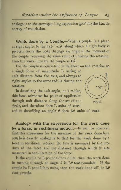
Work done by a Couple,—When a couple in a plane
at right angles to the fixed axis about which a rigid body is
pivoted, turas the body through an angle ^, the moment of
the couple retaining the same value (L) during the rotation,
then the work done by the couple is \S.
For the couple is equivalent in its effect on the rotation to
a single force of magnitude L acting at
unit distance from the axis, and always at
right angles to the same radius during the
rotation.
In describing the unit angle, or 1 radian,
this force advances its point of application
through unit distance along the arc of the yjo. 10.
circle, and therefore does L units of work,
and in describing an angle Q does Ld units of work.
Analogy with the expression for the work done
by a force, in rectilinear motion.—It will be observed
that this expression for the measure of the work done by a
couple is exactly analogous to that for the work done by a
force in rectilinear motion, for this is measured by the pro-
duct of the force and the distance through which it acts
measured in the direction of the force.
If the couple be L poundal-foot units, then the work done
in turning through an angle Q is L0 foot-poundals. If the
couple bo L pound-foot units, then the work done will be L^
foot-pounds.
Dynamics of Rotation.
Change of Kinetic Energy due to a Couple.—When the body on which the couple acts is perfectly free
to turn about a fixed axis perpendicular to the plane of the
couple, it is easy to see that the work done by the couple is
equal to the change in the kinetic energy of rotation.
For if A be the angular acceleration, a>^ the initial, and w
the final value of the angular velocity, then (see equation iii.
p. 4)
2 30> — CO
. . 17:
2A
and A=Y-;
= Final kinetic energy— Initial kinetic energy.
Radius of Gyration.—It is evident that if we could
condense the whole of the matter in a body into a single
particle there would always be some distance "k from the axis
at which if the particle were placed it would have the same
moment of inertia as the body has.
This distance is called the radius of gyration of the body
with respect to the axis in question. It is defined by the
relation
M 2m'
M being the mass of the body and equal to the sum of the
masses of its constituent particles.
[We may, if we please, regard any body as built up of a very
great number (n) of equal particles, each of the same mass,

Rotation under the Influence of Torqne, 25
which are more closely packed together where the matter
is dense, less closely where it is rare.
Then M=nm and 2(77ir')= 7n2r",
so that A;'=w— =—
,
iim n
ue. k* is the value obtained by adding up the squares of the
distances from the axis of the several equal particles and
dividing by the number of terms thus added together. That
is, we may regard k* as the average value of the square of the
distance from the axis to the several constituent equal par-
ticles of the rigid body.]
In a few cases, such as those of the thin hoops or thin hol-
low cylinder figured on p. 21, the value of the radius of
gyration is obvious from simple inspection, being equal to the
radius of the hoop or cylinder.
This is approximately true also for a fly-wheel of which the
mass of the spokes may be neglected in comparison with that
of the rim, and in which the width of the rim in the direction
of a radius is small compared to the radius itself.
Numerical Examples.—Wo now give a number of
numerical L'xanij)lc3, with solutions, in illustration of the prin-
ciples estal)li.shcd in tliis chapter. After reading these the
student should work for himself examples 1, 3, 6, 9, 10, 14,
and 15, at the close of Chapter III.
BzamplA 1.—A whed weighing 81 /&«., and whose radvut ofgyraUonit 8 inches^ it acted on by a couple whose moment it 5 vound-foot unitt
for half a minute ; find the rate of rotation produced,
Ut Method of <So/i4<u>n.—Taking 1 lb. ns unit moss. The unit
force ii the pouiidal
;
/. I(=Mit«) = 81 x(iy = 81 xllb..ft.«uuito = 36 unita.

26 Dynamics of Rotation,
Moment of force or torque=5xgr poundal-ft. units=5x32= 160
units (nearly)
;
angular acceleration =A= torque ^160^40moment of inertia 36 9
radians per sec. each second;
the angular velocity generated in half a minute
=o)=Ai= -^x 30 radians per sec.
400 ^.=-;r- radians per sec.
o
400 1 ,= -ir^TT- turns per sec3 Stt
= -^x '1589 turns per sec. = 1271*2 turns per minute.
2ud Method of Solution.—Taking the unit of force as 1 pound, then
the unit of mass is 1 slug = 32 lbs. (nearly),
81the mass of the body is ^ slugs,
Torque= 5 pound-foot units;
1 1 X- A torque ^ 9 40.*. angular acceleration = A = . \. .
—-^ = 5 -^ o = -?rmoment oi inertia 8 9
radians per sec. each second ;
.'., as before, the rate of rotation produced in one half-min.
= 1271 '2 turns per minute.
Example 2.
—
Find the torque which in one minute ivill stop the
rotation of a wheel whose mass is 160 lbs. and radius of gyration
1 ft. 6 in. and which is rotating at a rate of 10 turns per second.
Find also the number of turns the wheel will make in stopping.
\st Solution.—Using British absolute units. The unit of mass is
1 lb., the unit of force 1 poundal.
I = MA;2 = 160 X (I)units= 360 units.
Angular velocity to be destroyed=« = 10 x 27r radians per sec.=207r ;

Rotation under the Influejice of Torque, 27
,*. this is to be destroyed in 60 sec ; .'. angular acceleration required
«= —^=J radians per sec each second.60 3
The torque required to give this to the body in question
= moment of inertia x angular acceleration= 360 x —
»1207r poundal-foot units
120ir 15 , -.=——s=— rt pound-ft. units.
The ETerage angular velocity during the stoppage is half the initial
velocity, or 5 turns per second, therefore the number of turns made
in the 60 seconds required for stopping the* wheel = 60 x 5= 300.
2n(i Solution.—Using Engineer's or gravitation units. The unit
force is 1 pound. The unit mass is 1 slug = 32 lbs. nearly.
^ --,, 160 /3\2 ., 45 .,
I = MA;2= -—-x( YJ units = — units.
The angular velocity to be destroyed= 10 x 2ir radians per sec.
The time in which it is to be destroyed is 60 sec;
,'. angular acceleration =A= ^^=0 radians per sec. each secbO
The torque required to give this to the body in question
»IxA=-r x-;r-=-7-7r pound-ft. units as before.4 3 4
Example S,—A cord, 8 feet long, is torapped round the axle, 4 inches
in diameter, of a heavy wheel, and is pulled vnth a constant force of
m jxmnds till it is aU unvxmnd and comes off. The wheel is (hen
found to be rotating 90 times a minute ; find its moment of inertia.
^Million.—Using British absolute units. The unit of mass is 1 lb.
and of force 1 poundal.
The force of 60 pounds» 60 x 32 poundala. This is exerted through
a distance of 8 feet
;
.-. the work done by the force » 8 x 60 x 32 ft-poundals.
The K.E. of rotation generated - 4I«'-4Ix(^^^/-

28 Dynamics of Rotation.
Equating the two we have
ilx97r2=8x 60x32;. 1= 2x^x60x32 1^.^,,^^.,^^
On"*'
It will be observed that this result is independent of the diameter
of the axle round which the cord is wound, which is not involved in
the solution. The torque exerted would indeed be greater if the axle
were of greater diameter, but the cord would be unwound propor-
tionately sooner, so that the angular velocity generated would remain
the same.
JJdng Engineer's or gravitation unitSy the solution is as follows :—The unit of force is 1 pound and of mass 1 slug.
The work done by the 60 pound force in advancing through 8
feet= 8 X 60= 480 ft. pounds.
The K.E. of rotation generated =JIa)2=p x (^^i^^'^Vfoot-pounds
of work.
Equating the two we have
ilx97r2=480j
J 2 X 480, , -, „ ., V
I=Q 2
(slug-ft.2 umts)
2x480x32,, „,2 ., , »=—jr-s— Ib.-ft.'^ units as before.
Example 4.
—
A heavy wheel rotating 180 times a minute is brought
to rest in 40 sec. by a uniform friction of 12 pounds applied at a dis-
tance of lb inches from the axis. How long would it tale to be
brought to rest by the same friction if two small masses each weighing
1 lb. loere attached at opposite sides of the axw, and at a distance of
two feet from it.
Solution.—1st. Using Engineer's or gravitation units. The unit of
force is 1 pound and of mass 1 slug. In order to find the effect of in-
creasing the nioiuent of inertia we must first find the moment of inertia
Ij of the unloaded wheel This is directly as the torque required to
Rotation imder the Influence of Torgue. 29
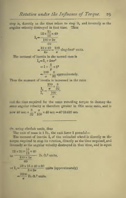
stop it, directly as the time taken to stop it, and inversely as the
angular velocity destroyed in that time. Thus
12xi^x40I — ^^
* 18()x27r
CO
15x40 100 , r *2B =— slug-foot' units.677 tr **
The moment of inertia in the second case is
Ij=Ii + 2mr*
= I +— x2«9
100 8 . , ,^— +— approximately.
Thus the moment of inertia is increased in the ratio
100 8^
rr
iind the time required for the same retarding torque to destroy the
same angular velocity is therefore greater in this same ratio, and is
now 40 sec. + 06 ^ 1^ ^ ^^ ^^^- =40-31416 sec
Or, Mting absolute uniti^ thus
The unit of mass is 1 lb., the unit force 1 poundal
—
The moment of inertia I, of the unloaded wheel is directly as the
torque required to stop its rotation, directly as the time required, and
inversely as the angular velocity destroyed in that time, and is equal
12x32x^^x40
60
. 32x16x40x60 .^ , , , .
or I,- 5
—
units (approximately)o X 2fr
3200,. .,, .
Ib.-ft.* units.

30 Dynamics of Rotation.
The moment of inertia in the second case
IT
.'. the moment of inertia is increased in the ratio of
3200 o 3200ho : ;
n IT
and therefore the time required for the same retarding torque to
destroy the same angular velocity is increased in the same proportion,
and is now
40 sec. + 40 sec. x -2iil=40-31 sec. approximately (as before).
Note to Chapter II.
In order to bring the substance of this chapter with greater vivid-
ness and reality before the mind of the student, we have preferred to
take it as a matter of observation and experiment that the power of a
force to produce angular acceleration in a rigid body pivoted about
a fixed axle is proportional to the product of the force and its distance
from the axis, i.e. to its moment in the technical sense. But this
result, together with the fact that what we termed the * rotational
inertia ' of a body is given by 2(mr2), might have been obtained as a
direct deduction from Newton's Laws of Motion. We now give
this deduction, premising first a statement of d'Alembert's Principle,
which may be enunciated as follows :* In considering the resultant
mass-acceleration produced in any direction in the particles of anymaterial system, it is only necessary to consider the values of the
external forces acting on the system.'
For every force is to be measured by the mass-acceleration it pro-
duces in its own direction (Newton's Second Law of Motion), andalso every force acts between two portions of matter and is accom-
panied by equal and opposite reaction, producing an equal andopposite mass-acceleration (Newton's Third Law). The action andreaction constitute what we call a stress. When the two portions of
matter, between which a^ stress acts, are themselves parts of the
system, it follows that the resultant mass-acceleration thereby pro-
duced in the system is zero. The stress is in this case called an
internal stress, and the two forces internal forces. But though the
forces are internal to the system, yet they are external, or, as Newton

z
Rotation under the Influence of Torq^ie. 3
1
called them, 'impressed' forces on the two particles respectively.
Hence, considering Newton's Second Law of Motion to be the record
solely of observations on particles of matter, we may count up the
forces acting in any direction on any material system and write them
equal to the sum of the mass-accelerations in the same direction, but
in doing so we ought, in the first instance at any rate, to include these
internal forces, thus
' external forces \,x>( internal forces \_2 /mass-accelerationX
in any direction) I in same direction J ^ I in same direction)
We now see that 2(intemal forces)= 0.
Hence we obtain as a deduction
. /external forces\ _ ^ /'n)ass-accelerations\
Vin any direction/ V ^^ same direction /'
or 2E= 2(7wa).
This justifies the extension of Newton's law from particles to bodies
or systems of particles. If any forces whatever act on a free rigid
body, then whether the body is thereby caused to rotate or not, the
sum of the mass-accelerations in any direction is equal to the sum of
the resolutes of the applied forces in the same direction.
Now, since the line of action of a force on a particle is the same as
the line of the mass-acceleration, we may multiply both the force and
the mass-acceleration by the distance r of this line from the axis, and
thus write
the moment about any axis of "j ( moment of the mass-accelera-
the force, on any particle, }• = S tion> along that line, of the
along any line, J ( same particle,
and, therefore, summing up the results for all the particles of any
system, we have
{moments about any axis of) ( moments about the sameJ
all the forces acting on the > = 2 < axis of the mass-acccle- >
particles of the system ) ( rations of the particles, )
^. - /moments of the extemalX ,« /moments of the intemal\
^'^V foroet j+^V forces )
= 2 /moments of the mass-X
\ accelerations. /
Now, not only are the two forces of an internal stress between two

32 D)mam ics of Rotation
.
particles equal and opposite, but they are along the same straight liney*
and hence have equal and opposite moments about any axis what-
ever, hence the second term on the left side of the above equation is
always zero, and we are left with
_ /moments of the external\ _^ /moments of the massAV forces / \ accelerations. /
Now, we may resolve the acceleration of any particle into three
rectangular components, one along the radius drawn from the particle
perpendicular to the axis, one parallel to the axis, and one perpen-
dicular to these two. It is only this latter component (which we will
call ap) that has any moment about the axis in question, and its
moment is rap, where r is the length of the radius.
Thus the moment of the mass-acceleration of any particle of mass
m may be written mrap.
Now, in the case of a particle which always retains the same dis-
tance (r) from the axis, ap is the rate of increase of the tangential
speed T, and if a> be the angular velocity about the axis, 'o=r(ii. So
that ap= rate of increase of rw.
Also, r being constant, the rate of increase of rw is r times the rate
of increase of a>. Hence, in this case, ap= rd>f and if, further, the
whole system consists of particles so moving, and with the same
angular velocity, i.e. if it is a rigid body rotating about a fixed axle,
then for such a body so moving
2 (moments of the mass-accelerations) = 2mrra).
= (o2mr".
Hence, in this case
2 (moments of the external forces) = angular acc'^ x 2{mr^
or the angular acceleration = S^^^I^^Ll^ffi!
.
2{mr^)
* This is, perhaps, not explicitly stated by Newton, but if it were not
true, then the action and reaction between two particles of a rigid
body would constitute a couple giving a perpetually increasing rotation
to the rigid body to which they belonged, and affording an indefinite
supply of energy. No such instance has been observed in Nature.

CHAPTER III.
DEFINITIONS, AXIOMS, AND ELEMENTARY THEOREMS NECES-
SARY FOR DEALING WITH MOMENTS OF INERTIA.
ROUTH'S rule AND ITS APPLICATION.
CJoNSTANT use will be made of the following Definitions
and Propositions.
Definition.—By a slight extension of language we speak
of the moment of inertia of a given area with respect to any axis,
meaning the moment of inertia which the figure would have
if cut out of an indefinitely thin, perfectly uniform rigid
material of unit mass per unit area, so that the mass of the
figure is numerically equal to its area. This dynamical defini-
tion becomes purely geometrical, if we say that the moment of
inertia, with respect to any axis, of an area A, and of which
the indefinitely small parts a„ o„ a„ . . . are at distance
r„ ft, . . . from the axis, is equal to
a,r,'-fa,r,«-fa,r,"4. . . .
=v(a/*).
It will be observed that the area may be either plane or
curved.
Definition.—In the same way the moment of inertia
about any axis of any solid figure or volume V, of which
V, V, r, . . . are the indefinitely small constituent parts,
may be defined as

34 Dynamics of Rotation.
Axiom.—The moment of inertia of a body with respect to
any axis is the sum of the moments of inertia of any con-
stituent parts into which we may conceive it divided, and
similarly the moment of inertia with respect to any axis of any
given surface or volume is equal to the sum of the moments
of inertia of any constituent parts into which we may con-
ceive the surface or volume divided. This follows from the
definitions just given.
Illustration.—Thus the moment of inertia of a peg-top,
shaped as in the figure, about its axis of re-
volution, is equal to the moment of inertia of
the hemispherical dome of wood ABC-}- that
of the conical frustum ABDE-f that of the
conical point of steel DE.
Axiom.—It is evident that the radius of
gyration of any right prism of uniform density
about any axis perpendicular to its base is the same as that
of the base. For we may conceive the solid divided by an in-
definite number of parallel planes into
thin slices, each of the same shape as
the base.
Thus, if Z; be radius of gyration of
the basal figure, and M the mass of
the prism, the moment of inertia is
MA;* units, and this holds whether
the axis cuts the figure as OaO'j, or
does not cut it as OiO'i.
Thus the problem of finding the
moment of inertia of an ordinary
lozenge-shaped compass needle, such
as that figured, reduces to that
O/
o;
g\^. 12.

Moments of Inertia—Elementary Theorems, 35
of finding the radius of gyration about 00' of the horizontal
cross-section ABCD.
Proposition \,— The moment of
mertia of a lamina abijut any axis Oz
perpendicvlar to its plane^ is equal to the
8um of its moments of inertia about any
two rectangular axes Ox and Oy in its
plane, and intersecting at the point where the axis Oz meets the
plane of the lamina. Or,
in an obvious notation,
I.=Ix+I,.
Proof.—From the figure
we have at once
I,=2(mr')
=2m(x'+y*)
=1mx*-{-2my*
no. 14.
Bzamiaa.— We have al-
ready seen that a thin hoop of radius r and mass m has a momentof inertia Mr* about a central
"
axis perpendicular to its plane.
Let I be ita moment of inertia
aboat a diameter. Then I ia
also its moment of inertia about
a Moond diameter perpendicular
to the former; .'. by this pro-
petition
2I-Mr«;
.-. I-Mr*
ic* the moment of inertia of
a hoop about a diameter is only
half that about a oeotral axis perpendicular to the pkne of the hoop

36 Dynamics of Rotation.
Routh's Rule for finding the Moment of Inertia
about an Axis of Symmetry in certain cases.—Whenthe axis about which the moment of inertia is required passes
through the centre of figure of the body and is also an axis
of symmetry, then the value of the moment of inertia in a
large number of simple cases is given by the following rule of
Dr. Routh :—
Moment of inertia about an axis of symmetry
—M V ^^^™ ^^ ^^ squares of the perpendicular semi-axes
3, 4, or 5,
T 2_ sum of the squares of the perpendicular semi-axes
The denominator is to be 3, 4, or 5, according as the body is
a rectangle, ellipse (including circle), or ellipsoid (including
sphere).
This rule is simply a convenient summary of the results
obtained by calculation. The calculation of the quantity
2(m7'^) is, in any particular case, most readily performed by the
process of integration, but the result may also be obtained, in
some cases, by simple geometry. We give in Chapter IV.
examples of the calculation in separate cases, and it will be
seen that they are all rightly summarised by the rule as given.
Examples of tlie Application of Dr. Routh's Rule.—To find the
radius of gyration in the following cases :
—
(1) 0/ a rectangle of sides (2a) and (2b) about a central
axis perpendicular to its plane.
Here the semi-axes, perpendicular to each other and
to the axis in question, are a and b ; therefore, apply-
ing the rule, we have
Fia. 16. k"^-a2 + 6«
3
(2) Of the same rectangle about a central axis in its plane per-
pendicular to one side (b). Here the semi-axes, perpendicular to
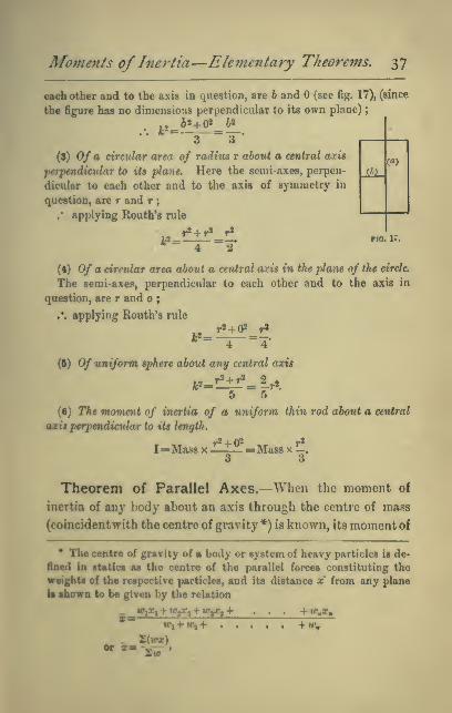
Moments ofInertia—Eleynentary Theorems, 37
each other and to the axis in question, are 6 and (see fig. 17), (since
the figure has no dimensions perpendicular to its own plane)
;
•^' 3" ~3 •
(3) 0/ a circular area of radius r about a central axis
perpendicular to its plane. Here the semi-axes, perpen-
diailar to each other and to the axis of symmetry in
question, are r and r;
/ applying Routh's rule
ShLW
FIO. 17
(4) 0/ a circular area ahont a central a:cis in the plane of the circle.
The semi-axes, perpendicular to each other and to the axis in
question, are r and o ;
.'. applying Routh's rule
~ 4 4*
(5) Of uniform sphere about any central axis
* 5" "5
(•) The moment of inertia of a uniform thin rod about a central
axisptrpmdieular to its length.
I=Mas8 X—1_ =Mass x _.
Theorem of Parallel Axes.—When the moment of
inertia of any body about an axis through the centre of mass
(coincidentwith the centre of gravity *) is known, its moment of
• The centre of gravity of a body or system of heavy particles is de-
fined in statics as the centre of the parallel forces constituting the
weights of the respective particles, and its distance x from any plane
la shown to be given by the relation
WiXi +Wtr^^w^+ . . . •ftf,g,
IPl+IO,+ +IC,
2(ipx)

38 Dynamics of Rotation,
inertia about any parallel axis can be found by applying the
following proposition :
—
Proposition II.
—
The moment of inertia ofany body about any
axis is equal to its moment of inertia about a parallel axis through
its centre of mass, plus the moment of inertia which the body would
have about the given axis if all collected at its centre of mass.
Thus, if I be the moment of inertia about the given axis,
Ig that about the parallel axis through th*e centre of mass,
and R the distance of the centre
of gravity from the given axis,
and M the mass of the body.
I=I,+MR^Proof—Let the axis of rota-
tion cut the plane of the dia-
gram in 0,and let a parallel axis
FIG. 18. ^^ through the centre of mass (or
centre of gravity) of the body
cut the same plane in G, and let P be the projection on this
where tOj, 102 .... are the weights of the respective particles,
and Xi, x^ . . . . their distances from the plane in question.
Now, since the weight {iv) of any piece of matter is found by ex-
periment to be proportional to its mass or inertia (m), we may substi-
tute (m) for (w) in the above equation, and we thus obtain
_ _ 2{mx)*- 27n *
For this reason the point in question is also called the centre of mass, or
centre of inertia.
If the weiglit of {i.e. the earth-pull on) each particle were not pro-
portional to its mass, then the distance of the centre of gravity from
any plane would still be -4r- J hut the distance of the centre of mass
from the same plane would be ~—•' and tho two points would not
then coincide.
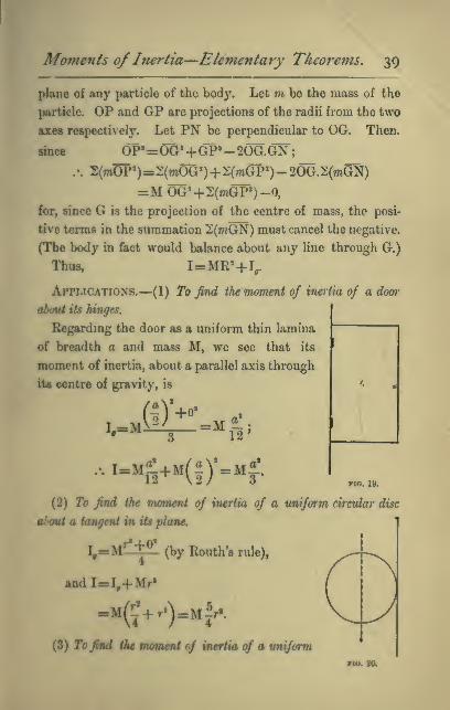
Moments of Inertia—Elementary Theorems. 39
plane of any particle of the body. Let m be the mass of the
particle. OP and GP are projections of the radii from the two
axes respectively. Let PN be perpendicular to OG. Then.
sinoe OP'=OG»+GP"-20G.GN;.-. 2(mOP*)=2(mOG»)+2(mGP»)-20G.5:(wGN)
=MOG*4-2(7nGP')-0,
for, since G is the projection of the centre of mass, the posi-
tive terms in the summation 2(mGN) must cancel the negative.
(The body in fact would balance about any line through G.)
Thus. I=MR=+V
Applications.—(1) To find the moment of inertia of a door
aboni Us hinges.
Regarding the door as a uniform thin lamina
of breadth a and mass M, we see that its
moment of inertia, about a parallel axis through
its centre of gravity, is
... .-MS+M(|y.Mf.no. ly.
(2) To find the moment of inertia of a uniform circular disc
about a tangent in its plane.
_M'l+?'I,=M (by Routh's rule),
andI=I,+ Mr«
(3) Tojkd the moment of inertia of a uniform

40 Dynamics of Rotation,
bar or other prism about a central am perpendicular to its length,
where the bar is not thin.
(For example of a bar-magnet
of circular cross-section suspended
by a fine thread as in the fig.)
For the sake of being able to
deal with a case like this, which
is of very common occurrence,
we shall prove the following :
—
no. 21.
Proposition III.
—
The moment of inertia of any uniform
right prism, of any cross section whatever about a central axis
perpendicular to the line joining the centres of gravity of the ends,
is equal to the moment of inertia of the same prism considered as
a thin bar, plus the moment of inertia that the prism would
have if condensed by endwise contraction into a single thin slice
at the axis.
Proof—Let g, gi, be the centres of gravity of the ends of
the prism.
itt ^^^no. 22.
Imagine the prism divided into an indefinite number of
elementary thin slices by planes parallel to the ends. The

Moments of Inertia—Elementary Theorems, 41
line ^, ^1, contains the centre of gravity of each slice and of
the whole prism. Let r be the distance of any one of these
slices from the centre of gravity (G) of the whole prism, and mthe mass of the slice. Then the moment of inertia i of this
slice about the given axis 00' is, by the theorem of parallel
axes, given by t= /,
+
mr^^
where », is the moment of inertia of the slice about a parallel
axis through its centre of gravity\
,\ the whole moment of inertia I required is
I=2(t,+7nr>)
and It, is the same as the moment of inertia I, of all the slices
condensed into a single slice ; thus the proposition is proved.
This theorem is of use in questions involving the oscillations
of a cylindrical bar magnet under the influence of the hori-
zontal component of the earth's magnetic force.

42 Dynamics ofRotation.
Examples for Solution.
{In these, as in all other Examples in the hook, the answers given
are approximate only. Unless otherwise stated^ the value of g is taken
as 32 feet per second each second, instead 0/ 32 '19.)
(1) A heavy wheel has a cord 10 feet long coiled round the axle.
This cord is pulled with a constant force of 25 pounds till it is all
unwound and comes off. The wheel is then found to be rotating
5 times a second. Find its moment of inertia. Also find how long
a force of 5 pounds applied at a distance of 3 inches from the axis
would take to bring the wheel to rest.
Ans. (1) 16-2 lb. -ft.2 units.
(2) 1272 sec.
(2) A uniform door 8 feet high and 4 feet wide, weighing 100 lbs.,
swings on its hinges, the outer edge moving at the rate of 8 feet per
second. Find (1) the angular velocity of the door, (2) its moment of
inertia with respect to the hinges, (3) its kinetic energy in foot-pounds,
(4) the pressure in pounds which when applied at the edge, at right
angles to the plane of the door, would bring it to rest in 1 second.
Ans. (1) 2 radians per sec.
(2) 533-3 lb.-ft.2 units.
(3) 33-3 (nearly).
(4) 8*3 pounds (nearly).
(3) A drum whose diameter is 6 feet, and whose moment of inertia
is equal to that of 40 lbs. at a distance of 10 feet from the axis, is
employed to wind up a load of 500 lbs. from a vertical shaft, and is
rotating 120 times a minute when the steam is cut off. How far
below the shaft-mouth should the load then be that the kinetic energy
of wheel and load may just suffice to carry the latter to the surface ?
Ans. 41*9 feet (nearly).
(4) Find the moment of inertia of a grindstone 3 feet in diameter
and 8 inches thick ; the specific gravity of the stone being 2*14.
Ans. 709-3 lb.-ft.2 units.

Examples on Chapters /., //., and III. 43
(6) Find the kinetic energy of the same stone when rotating
5 times in 6 seconds. Ans. 303 7 ft.-pounds.
(6) Find the kinetic energy of the rim of a fly-wheel whose exter-
nal diameter is 18 feet, and internal diameter 17 feet, and thickness
1 foot, and which is made of cast-iron of specific gravity 72, when
rotating 12 times per minute.
(.V.A—Take the mean radius of the rim, viz. 8| feet, as the radius
of gyration.) Ans. 233G0 ft.-pounds (nearly).
(7) A door 7^ feet high and 3 feet wide, weighing 80 lbs., swings
on its hinges so that the outward edge moves at the rate of 8 feet
per sec. How much work must be expended in stopping it ?
Ans. 853*5 foot-poundals or 26'67 foot-pounds (very nearly).
(8) In an Atwood's machine a mass (M) descending, pulls up a
mass (m) by means of a fine and practically weightless string passing
over a pulley whose moment of inertia is I, and which may be
regarded as turning without friction on its axis. Show that the ac-
celeration a of either weight and the tensions T and i of the cord at
the two sides of the pulley are given by the equations
a=-V- . . . W
aJ^, . . . (U)
a»r<o =—^-|
—
- . . . (ill)
where r^ radius of pulley.
What will equation (iii) become if there is a constant friction of
moment (2) about the axis ?
r>(T-t-:|-)Ans. a= ,
—
(9) A wheel, whose moment of inertia is 50 Ib.-ft.* units, has a
horizontal axle 4 inches in diameter round which a cord is wrapped,
to which a 10 lb. weight is hung. Find how long the weight will
take to descend 12 feet. Ans. 11*66 sea (nearly).
2>trM<iofW.—Let time required =< sec. Then the avenge velocity
during the deooent U - - feet per sec , and alnco this has been acquired

44 Dyna7nics of Rotation,
at a uniform rate the final velocity of the weight is Iwico. this. Knowingnow the final velocity (r) of the cord and the radius (r) of the axle we
have tlic angular velocity a)= - of the wheel at the end of the descent,
and can now express the kinetic energies of both weight and wheel.
I'lic sum of these kinetic energies is equal to the work done by the
earth's pull of 10 pounds acting through 12 feet, i.e. to 12x10 foot-
pounds or 12 X 10 X 32 foot-poundals. This equality enables us to find t.
(10) Find the moment of inertia of a wheel and axle when a 20 lb.
weight attached to a cord wrapped round the axle, which is horizon-
tal and 1 foot in diameter, takes 10 sec. to descend 5 feet.
Ans. 1595 lb.-ft.2 units.
Directio7is.—Let the moment of inertia required be I Ib.-ft,^ units.
5The average linear velocity of the weight is jq^-^*
2x5Hence final =^^ f.s. =1 f.s. =r.
space traversed per sec. by point on circumference of axle
Angular velocity (a,)=radius of axle
-1-2
Now equate sum of kinetic energies of weight and wheel to work done
by earth's pull during the descent.
(11) A cylindrical shaft 4 inches in diameter, weighing 84 lbs.,
turns without appreciable friction about a horizontal axis. A fine
cord is wrapped round it by which a 20 lb. weight hangs. How long
will the weight take to descend 12 feet 1 Ans. t = l'52 sec.
(12) If there were so much friction as to bring the shaft of the
previous question to rest in 1 minute from a rotation of 10 turns per
sec, what would the answer have been ? Ans. \/|||^ of 1*52 sec.
(13) Two weights, of 3 lbs., and 5 lbs., hang over a fixed pulley in
the form of a uniform circular disc, whose weight is 12 oz. Find the
time taken by either weight to move from rest through ff feet.
Ans. J sec.
(14) Find the moment of inertia of a fly-wheel from the following
data :—The wheel is set rotating 80 times a minute, and is then
thrown out of gear and brought to rest in 3 minutes by the pressure

Examples on Chapters /., //., a7id III. 45
of a friction brake on the axle, which is 18 inches in diameter. The
normal pressure of the brake, which has a plane surface, is 200
pounds, and the coefficient of friction between brake and axle is '6.
Ans. 61890 lb.-ft» units.
(15) Prove that when a model of any object is made of the same
material, but on a scale n times less, then the moment of inertia of
the real object is n* times that of the model about a corresponding
(16) Show that, on account of the rotation of each wheel of a
carriage, the effective inertia is increased by an amount equal to the
moment of inertia divided by the square of the radius.
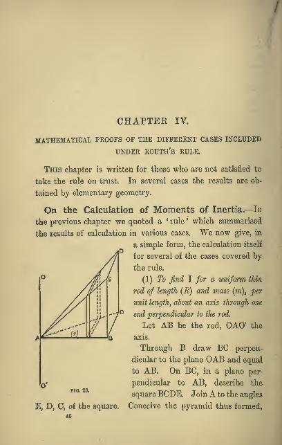
CHAPTER IV.
MATHEMATICAL PROOFS OF THE DIFFERENT CASES INCLUDED
UNDER ROUTH'S RULE.
This chapter is written for those who are not satisfied to
take the rule on trust. In several cases the results are ob-
tained by elementary geometry.
On the Calculation of Moments of Inertia.—In
the previous chapter we quoted a * rule ' which summarised
the results of calculation in various cases. "We now give, in
a simple form, the calculation itself
for several of the cases covered by
the rule.
(1) To find I for a unifoi'm thin
rod of length (R) and mass (m), per
unit length, about an axis through one
end perpendicular to the rod.
Let AB be the rod, OAO' the
axis.
Through B draw BC perpen-
dicular to the plane OAB and equal
to AB. On BC, in a plane per-
pendicular to AB, describe the
square BCDE. Join A to the angles
Conceive the pyramid thus formed,
Fio. 23.
E, D, C, of the square
40

Moments ofInertia—Mathematical Proofs, 47
which has A for vertex and the square for base, to be filled
with uniform matter of which the mass per unit volume is
the same as the mass of the rod per unit length, viz. m.
Next, conceive the pyramid to be divided into an indefinite
number of very thin slices by planes very near together and
parallel to the square base.
To each slice there corresponds an elementary length of the
rod. Let r be the distance of one of these elements from A,
and « its very small length. Then its mass is tti.s., and its
moment of inertia is m,i.r^.^ but this is also the mass of the
slice since its area is r* and its thickness is 5.
Thus the moment of inertia of each element of the rod is
the same as the mass of the corresponding slice of the pyramid,
and consequently the moment of inertia of the whole rod is
the same as the mass of the whole pyramid,
(.«. 1= volume of pyramid x mass of unit volume
^\ ai^ea of base X altitude X
m
= ^*Xm^,
but mR is the mass of the whole rod=M
;
.-. I=Mxf
.
Cbr0/2ary.—If the rod extended to an equal distance AB'
naM.
on the other side of the axis, the moment of inertia of the
additional length would be the same;

48 Dynamics of Rotation,
.-. the whole moment of inertia would now be
but 2M would be now the mass of the whole rod.
Hen<;e we see that for a uniform rod of length 2i2, and mass
M about a central axis perpendicular to its length
..Mf.
(It will be observed that this agrees with Routh's
rule.)
(2) Case of a rectangle of sides 2a and 26, turning about a
central axis in its plane^ perpendicular to one side (say to the
side of length 2a).
It is obvious at once that the radius of gyra-
tion for the rectangle is the same as that of any
of the narrow strips into which it may be
divided by lines perpendicular to the axis.
Hence L=M'
Similarly, about a central axis in its plane,
perpendicular to the side of length 2b, the
moment of inertia I5=M—
(3) Hence, by Proposition I., p. 11, the momentof inertia about a central axis perpendicular to
the plane of the figure
3
which again is the expression in Routh's rule.
(4) To find I for a uniform thin circidar disc of mass M with
respect to a central axis perpendicular to its plane.
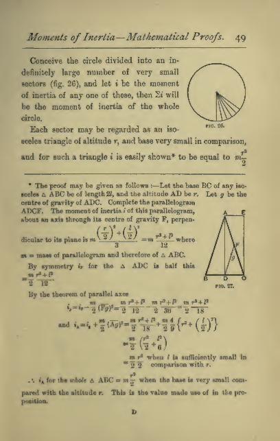
Moments of Inertia—Mathematical Proofs. 49
Conceive the circle divided into an in-
definitely large number of very small
sectors (fig. 26), and let i be the moment
of inertia of any one of these, then 2t will
be the moment of inertia of the whole
circle.
Each sector may be regarded as an iso-
sceles triangle of altitude r, and base very small in comparison,
and for such a triangle i is easily shown* to be equal to m—2
• The proof may be given as follows :—Let the base BC of any iso-
sceles L ABC be of length 2<, and the altitude AD be r. Let g be the
centre of gravity of ADC. Complete the parallelogram
ADCF. The moment of inertia i of this parallelogram,
about an axis through its centre of gravity F, perpen-
i.m(iHl)=m!f+Jldicolar to its plane is m ^ ^ ^ =m —vc— where3 12
m m muM of parallelogram and therefore of A ABC.
By symmetry if for the ^ ADC is half this
By lbs thsorsm of parallel axai
. . ••»-«--, m r'-t-i' m H-t-P m r^+l^•»•»" 2^^r--§ 12 "2 8tf ^2"l8~
mr* when / ia snifidsntly imall in
*?? comparison with r.
. *. i'a for the vhoU A ABC » m .j when the base is very small com-
pared with the altiiode r. This is the valoe SMde nss of in the pro*

so Dynamics of Rotation.
where m is the mass of the triangle.
which is the value given by Eouth's rule.
Each of these results would have been obtained much more
briefly by integration. Thus, for a uniform thin rod of length,
2/ and mass M turning about
a central axis perpendicular
to its length, the moment of
inertia of any elementary
length, dr at distance r
=mass of element Xr*
dr
Fio. 28.
= M XTj^Xr'
moment of inertia of whole rod= I -^r'^dr
In the case of a uniform circular
disc of mass M and radius a
turning about a central axis per-
pendicular to its plane, we may
conceive it divided into a succession
^^^ ^jjof elementary concentric annuli, each

Moments of Inertia— Mathematical Proofs, 5
1
of breadth dr. If r be the radius of one of these, its moment
of inertia
smass of annulus Xr*
ira*
a'
... .-™/5,.¥-
Moment of Inertia of an Ellipse.—This is readily
obtained from that of the circle. For the circle ABC of radius
A becomes the ellipse ADC with semi-
axes a and 6 by projection. Every
length in the circle parallel to OB
being diminished in the ratio r^^-
while lengths parallel to OA remain
unaltered. Thus any elementary area
in the circle is diminished in the ratio
-and at the same time brought nearer
1% ^v
/ ^^ '^'^l \1/^^
! 1 1
^jt /
nasa
to OC in the same ratia
Hence
Momeot of meriia of ellipse about major axis= moment of
of eirde about same axis x - X -a V
5«
or h 6«' ^~A—
1 X — X -KJ a a*
a 4
-MaMofclUpMX^
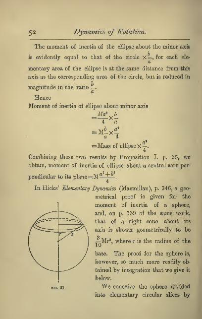
52 Dynamics of Rotation.
The moment of inertia of the ellipse about the minor axis
is evidently equal to that of the circle X — , for each ele-
mentary area of the ellipse is at the same distance from this
axis as the corresponding area of the circle, but is reduced in
magnitude in the ratio —
.
Hence
Moment of inertia of ellipse about minor axis
Taa 4
= Mass of ellipse X —
.
Combining these two results by Proposition I. p. 35, we
obtain, moment of inertia of ellipse about a central axis per-
2 I T 2
pendicular to its plane=M ^ "*.
In Hicks' EUmentary Dynamics (Macmillan), p. 346, a geo-
metrical proof is given for the
moment of inertia of a sphere,
and, on p. 339 of the same work,
that of a right cone about its
axis is shown geometrically to be
3—Mr', where r is the radius of the
base. The proof for the sphere is,
however, so much more readily ob-
tained by integration that we give it
below.
We conceive the sphere divided
into elementary circular slices by
no. 81

Moments of Inertia—Mathematical Proofs, 53
planes perpendicular to the diameter, about which the
moment of inertia is sought, each slice being of the same
elementary thickness dr.
If r be the distance of any such slice from the centre, its
moment of inertia about the said diameter is
mass of slice x^^^—^'
=?MxLV8a» 15
= Mx4a«5
=: M^l+l' as stoted in Routh's Rule.
The student who is acquainted with the geometry of the
ellipsoid will perceive that the moment of inertia of an
eUipioid may be obtained from that of the sphere by projeo-
tion, in the same way that we obtained the result for the
ellipM from that of the circle.
InralMa—Fiod tb« nMiioi of gyimttoa of~
(1.) A tqasra of tide « about a dlagoDsL
(S.) A n^cbt-sngled tiiangls of fides a and 6, containing the right-
agit abooi iho tide a.
An». i>-^

54 Dynamics of Rotation.
(3.) An isosceles triangle of base h about the perpendicular to the
biise from the opposite angle.
(4.) A plane circular annulus of radii K and r about a central axis
perpendicular to its plane.
Ans. lc^=-2
(5.) A uniform spherical shell of radii R and r about a diameter.
Directions.—Write (M)= mass of outer sphere, supposed solid ; (wi)
that of inner. Moment of inertia of shell =(M-rn)fc- = difference
between the moments of inertia of the two spheres. Also since
;^= =p=, we have m=M:^and M-m=M^—— . Thus all the massesM R' R^ R'
can be expressed in terms of one, which then disappears from the
equation.

CHAPTER V
FUSTHIR PROPOSITIONS CONCKRKING MOMENTS OF INERTIA
—PRUiClPAL AXES—GRAPHICAL CONSTRUCTION OF IN-
ERTU CURVES AND SURFACES—EQUIMOMENTAL SYSTEMS
—INERTIA SKELETONS.
Wl have shown in Chapters iii. and iv. how to obtain the
momenta of inertia of certain regular figures about axes of
•ymmetry, and axes parallel thereto. The object of the
present chapter is to acquaint the student with certain impor-
tant propodtions applicable to rigid bodies of any shape, and
by meaoB of which the moment of inertia about other axes
cmn be determined. The proofs given require the application
of only elementary solid geometry ; but should the student
find himielf unable to follow them, he is recommended, at a
firrt reading of the subject, to master, nevertheless, the mean-
ing of the propositions enunciated and the conclusions reached,
and not to let the geometrical difficulty prevent his obtaining
a knowledge of important dynamical principles.
PBorosmoN TV.—In am^ riffid body, ike mm o/ikemommU
of inertia obant any thru reeUmgular tuee, dmum thnmgh a gieen
painijiaud in the body, it eontUmi, whatever be the potitione of the
Let Ox, Ojr, O2, be any three rectangular axce drawn
through the fixed point 0. Let P be any particle of the body
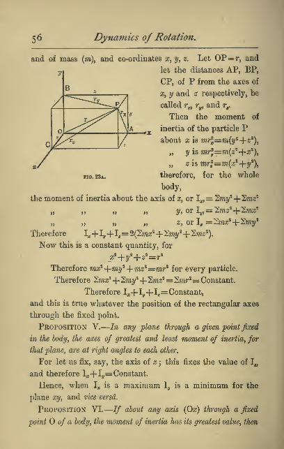
56 Dynamics of Rotation,
and of mass (m), and co-ordinates jc, y, z. Let OP=r, and
let the distances AP, BP,
CP, of P from the axes of
X, y and z respectively, be
called r^^ Ty, and r^
Then the moment of
inertia of the particle Pabout X is mr^=m(«/=4-«').
„ y is wrj=m(2!'4-a;'),
„ z is mr^=m{x^-{-y^),
therefore, for the whole
body,
no. 28a.
the moment of inertia about the axis of x, or I^,= '2my^-\-^mz^
„ „ „ „ y,orly,= ^mz^-\-^mx^
„ „ z, or I, =:^mx^-{-^my*
Therefore I^+1,,+ 1.
=
2{2mx^+ ^rny'+ ^mz^).
Now this is a constant quantity, for
Therefore mx^ -{-my^ -\-mz^ =mr^ for every particle.
Therefore '27nx'^+ 'Imy^+ ^mz'^= 2?wr^= Constant.
Therefore I,,+1^+1,= Constant,
and this is true whatever the position of the rectangular axes
through the fixed point.
Proposition V.
—
In any plane through a given point fixed
in the body, the axes of greatest and least moment of inertiay for
that plane, are at right angles to each other.
For let us fix, say, the axis of z 3 this fixes the value of 1„
and therefore I;j-|-Iy= Constant.
Hence, when 1^ is a maximum ly is a minimum for the
plane xy, and vice versd.
Proposition VI.
—
If about any axis (Ox) through a fixed
point of a body, the moment of inertia has its greatest value, then

Principal Axes, 5 7
ahaiA some axis (Os), at right angles to Oz,it will have its least
value ; and abatU the remaining rectangular axis (Oy) the rnoment
of inertia will be a maximum for theplane yz^ and a minimum for
the plane tof.
For, let us suppose that we have experimented on a body
and found, for the point O, an axis of maximum moment of
inertia, Ox. Then an axis of least moment of inertia must
lie somewhere in the plane through 0, perpendicular to this,
for if in some other plane through there were an axis of
still smaller inertia, then in the plane containing this latter
azia, and the axis of x we could find an axis of still greater
inartia than Ox, which is contrary to the hypothesis that Ox
is a maximum axis.
Next, let us take this minimum axis as the axis of z. The
moment of inertia about the remaining axis, that of y, must
now be a maximum for the plane yz. For I, being fixed,
1,-1-Iy= constant, and therefore ly is a maximum since I, is
a tnii^imnm.
Again, I, being fixed, I,+1^= constant, and therefore I, is
a minimnm for the plane ary, since I, is a maximum.
DefinUione^—^McYi rectangular axes of maximum, minimum,
sod intermediate moment of inertia are called principal
axes for the point of the body from which they arc drawn,
and the momenta of inertia about them are called principal
moments of inertia for the point ; and a plane containing
two of the principal axes through a point is called a principal
plane for that point.
When the point of the body through which the rectangular
azea are drawn ia the Centre of Mass, then the principal axes
art ealled, jwr egcotUenee^ the principal axes of the body, and
the momenta of inertia about them the principal moments of
inertia of the body.
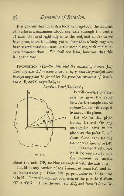
58 Dyniamics of Rotation,
It is evident that for such a body as a rigid rod, the moment
of inertia is a maximum about any axis through the centre
of mass that is at right angles to the rod, and so far as we
have gone, there is nothing yet to show that a body may not
have several maximum axes in the same plane, with minimum
axes between them. We shall see later, however, that this
is not the case.
Proposition NW—To show that the moment of inertia (Top)
about any axis OP making angles a, /?, y, mih the principal axes
through any point 0, /o?* which the principal moments of inertia
are A, B, and C respectively^ is
Acos^a
+
Egos'"/?+ Ccos^'y.
It will conduce to clear-
ness to give the proof
first, for the simple case of
a plane lamina with respect
to axes in its plane.
Let abc be the plane
lamina, Ox and Oy any
rectangular axes in its
plane at the point O, and
about these axes let the
moments of inertia be (A')
and (B') respectively, and
let it be required to find
the moment of inertia
about the axis OP, making an angle 6 with the axis of a;.
Let M be any particle of the lamina, of mass (m), and co-
ordinates X and y. Draw MN perpendicular to OP to meetit in N. Then the moment of inertia of the particle M about
OP is wMN*. Draw the ordinate MQ, and from Q draw QS
no. 244.

Principal Axes. 59
meeting OP at right angles in S. Then
MN'=OM«-ON»=x'+y'-(OS+SN)'
and OS is the projection of OQ on OP, and therefore equal to
zcosd and SN is the projection of QM on OP, and therefore
equal to y sin^
.-. MN"=a;«4-y'-(2cos^+ysin^)*
=a;'(l -cos'^)+y'{l -sin'^)- 2sin^cos%
=a;'sin*^+y'cos'^— 2sin^cos^icy
.*. Iop=2mMN'=cos'^27ny'4-sin*^2ma;'— 2sin^co8^2wucy
= A'cos'^+B'sin2^-2sin^cos^i:7;ia:y.
We shall now prove that when the axes chosen coincide with
the principal axes so that A' becomes A and B' B, then the fac-
tor 2);/u;y, and therefore the last term, cannot have a finite value.
For since the value A of the moment of inertia about 0, is
now a maximum, Iqp cannot be greater than A^ so that A — lop
cannot be a — 1» quantity whatever be the position of OP.
x.t, A—Acos*d^ ^sin'^-|-28in^cos^2mj!y cannot be—w,ie. ABin^d-'Bsin^d-\-2sin6co8d2mxy cannot be—
%
now, when OP is taken very near to Oaj, so that 6 is infinitesi-
nudly small, then also sin^ is infinitesimally small, while cos^
it equal to 1, and so that if 2may has a finite value, the two
firtt teims of this expression, which contain the square of the
tm«ll quantity sin^ may be neglected in comparison with
the last term, and according as this last term is +ve or ^ve^
•o will the whole expression be H-w or —ve.
Now, whether the small angle ^ is +V0 or —ve, cos^ is
always +w, and l{mxy) is always constant ; neither of these
factors then changes signs with $ ; but sin^ does change sign
with $; so that, the last term, and therefore the whole ex-
pression is -re when 6 is ^ve and very small.
Hence it is impossible that Siwxy can have a finite value.

6o Dynamics of Rotation.
But '^mrnj is constant whatever be the value of B, and there-
fore is zero or infinitesimally small even when d \s> finite;
therefore, finally,
Iop=^cos2^+^sin2(9
[If we prefer to describe the axis OP as making angles a
and ^ with the rectangular axes of x and y respectively.
Then in the above proof we have everywhere cosa for cos^,
and cos/3 for sin^, and
Iop=^cos 2a+5 cos2^.]
The proof of the general case for the moment of inertia
Iqp of a solid body of three dimensions about any axis OP,
making angles a, j8 and y, with maximum, minimum, and
intermediate rectangular axis, Oa;, 0?/, Oz is exactly analogous
to the above, only we have
0M«=a;'+y»+2S instead of OM'=fl;»+y*
and ON=a;cosa-}-ycos^+2;cos7, instead of ON=iCcosa4-ycos/?,
and cos'a+cos'^^+cos''7=l, instead of cos^a+ 008*^^=1,
whence it at once follows that instead of the relation
Iop=^'cos'^a4-^'cos'')8— 2cosacos/32ma;y,
we obtain
lop=^'cos'^a
+
Bco&^/S+ Ceos'y— 2cosacosj82ma:y
— 2co6jScosy l^'myz—2cosycosa2mzx.
And, as before, when A'=Ay and B'=B^ or C=Ct each of
the last three terms can be shown to be, separately, vanishingly
small, and therefore finally
Iop=^cos'^a+5cos''/?-j- C'cos'y.
Graphical Construction of Inertia-Curves and
Surfaces.—Definition.—By an ' iuertia-curve ' we mean a
plane curve described about a centre, and such that every
radius is proportional to the moment of inertia about the axis
through the centre of mass whose position it represents.
Similarly, a moment of inertia surface is one having the same
property for space of three dimensions.

Principal Axes. 6i
It is evident that we can now construct such curves or
surfaces when we know the principal moments of inertia of
the body.
(L) Construction of the inertia cwi-ve of any plane lamina for
axes in its plane.
Draw A and OB at right angles, and of such lengths that
they represent
the maximum y
and minimum
moment of in-
ertia on a con-
venient scale,
and draw radii
between them
at intervals of,
say, every 10^
Then mark oflf
on these in succession the corresponding values of the
expression
(5Aco8«^-f OBsin'^,
(which may be done graphically by a process that the student
will easily discover), and then draw a smooth curve through
the points thus arrived at. In this way we obtain the figure
OAof the diagram (Fig. 25a) in which the ratio .o. was taken
equal to -^ Complete inertia curves must evidently be Bym-
metrical about both axes, so that the form for one quadrant
gives Che shape of the whole.
If OA were equal to OB the curve would be a circle, for
if maximum and minimum values of the radius are equal, all
values are equal
no. 25a.

62 Dynamics of Rotation,
Figure 26a shows in a single diagram the shape of the
(1)
no. 26a.
curves when —=. has the values -^ry jr-, ^, and — respectively.Ul> (5 2 1
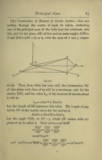
Principal Axes, 63
(II.) Construction of Moment of Inertia Surface.—Let any
section through the centre of mass be taken, containing
one of the principal axes of the body (say the minimum axis
Os), and let the plane zOC of this section make angles AOC=and BOC=(90'— ^) or 4>, with the axes of z and 1/ respec-
no. 27a.
lively. Then, from what has been said, the intersection OCof this plane with that of xy will be a maximum axis for the
section ZOC, and the value Iqo of the moment of inertia about
it will be
I^^=^C08'^-f 5C08'<^.
Let the length of OD represent this value. The length of any
radius OP of the inertia curve for the section is
^cos'a-f Bcos^p+Ccos^y.
Let the angle COP, or 90' -y, which OP makes with the
plane of ay be called 3. Then cos'ascos'AOP
gp gg cap
BCOS'^COS'd
QDt Qpi CTPU.4 co.V-oot'BOP-^-j^xgp.=co8'*co.'«
64 Dynamics of Rotation.
Therefore Iqp =^cos'^cos'S+j5cos'<^cos'S+Ccos'y
= (^ cos' (9+ 5cos2<^)cos28+ Ccos2y
= IqcCos^S+ Ccos'^y.
Therefore the inertia curve for the section zOO may he drawn
in precisely the same way as for a plane lamina^ and this result
holds equally well for all sections containing either a maxi-
mum or minimum or intermediate axis.
Inspection of the inertia curves thus traced (Fig. 26a) shows
that there is, in general, for any solid (except in the special
case when the curve is a circle), only one maximum axis
through the centre of mass, and one minimum axis, with a
corresponding intermediate axis.
Equimomental Systems.—Proposition Nlll.—Any
two rigid bodies of equal mass, and for which the three principal mo-
ments of inertia are respectively equal, have equal moments of inertia
about all corresponding axes. Such bodies are termed equimomental.
That such bodies must be equimomental about all corre-
sponding axes through their centres of mass follows directly
from the previous proposition ; and since any other axis must
be parallel to an axis through the centre of mass, it follows
from the theorem of parallel axes (Chapter iii. p. 37) that in
the case of bodies of equal mass, the proposition is true for
all axes whatever.
Any body is, for the purposes of Dynamics, completely
represented by any equimomental system of equal mass.
Inertia Skeleton.—Proposition IX
—
For any rigid
body there can be constructed an equimomental system of three
uniform rigid rods bisecting each other at right angles at its centre
of masSf and coinciding in direction with its principal axes.

Principal Axes. 65
For let (m!^ W, c6 (Fig. 27a) be three such rods, coinciding
respectively with the principal axes, Oa:, Oy, O2, and let the
moment of inertia of ao! about
a perpendicular axis through
Obe A'
while that of hV is Band that of cc* is OThen, for the system of rods,
If, therefore, the body in
question has corresponding
principal moments A^ J5, 6',
equimomental therewith when
yx
"*v^
the system of rods becomes
B-^rO^A (i)
a-^A'=B (ii)
A'-^B=0 (iii)
These three equations enable us to determine the values of
A\ Bf and C, to be assigned to the rods.
By addition we have,
2{A'^B'\'C)=A-\-BJt-C
or A'-\-B-\-a=\(A'\-B-JtC)
whence subtracting B-\-C=Awe have A'=i(B+C~A)and similar expressions for B' and C,
Such a system of rods we may call an imrtia skdeUm. Such
a skeleton, composed of rods of the same material and thick-
nem, and differing only in length, presents to the eye an
easily recognised picture of the dynamical qualities of the
body. The moment of inertia will be a maximum about the

66 Dynamics of Rotation.
direction of the shortest rod, and a minimum about the
direction of the longest.
[It may be mentioned that, for convenience of mathematical
treatment of the more difficult problems of dynamics, advan-
tage is taken of the fact that any solid can be shown to be
equimomental with a certain homogeneous ellipsoid whose
principal axes coincide with those of the solid. Also that if
we had chosen to trace inertia curves by making the radius
everywhere inversely proportional to the radius of gyration^
i.e. to the square root of the moment of inertia, then the curve
for any plane would have been an ellipse, and the inertia-
surface an ellipsoid.]

CHAPTER VL
SIMPLE HABHONIC MOTION.
The definition of Simple Harmonic Motion may be
given as follows :
—
Let a particle P travel with uniform speed round the cir-
cumference of a fixed circle, and let N be the foot of a per-
pendicular drawn from P to any
fixed line. As P travels round the
eircle N oscillates to and fro, and
ia said to have a simple harmonic
motion.
It is obvious that N oscillates
between fixed limiting positions
N« N| which are the projections on
the fixed line of the extremities
A and B of the diameter parallel
to it, and that at any instant the
velocity of N is that part of P'a
vdoetty whieh is psndlel to the fixed line, or, in other wordii
thb rtiodtiy of N is the velocity of P resolved in the direetion
of the fixed line. Also the aeceleration of N is the accelera-
tion of P resolved along the fixed line.
Now the leeeleration of P is constant in magnitude, and
always directed towards the centre of the oircle, and it
equal to jmrm*m(fC)m* ; cooseqaently Uie aeceleration oT
no. tt.

68 Dynamics of Rotation,
N=(i>'xthe resolved part of PC in the direction of the fixed
line=a)' X (NO), being the projection of C on the fixed line.
Thus we see that a particle with a simple harmonic motion
has an acceleration which is at any instant directed to the
middle point about which it oscillates, which is proportional
to the displacement from that mean position, and equal to
this displacement multiplied by the square of the angular
velocity of the point of reference P in the circle.
We shall see, very shortly, that the extremity of a tuning-
fork or other sonorous rod, while emitting its musical note of
uniform pitch performs precisely such an oscillation. Hence
the name ' Simple Harmonic'
The point in the figure corresponds to the centre of
swing of the extremity of the rod or fork, and the points
Nq Nj to the limits of its swing.
The time T taken by the point N to pass from one ex-
tremity of its path to the other, and back again, is the time
taken, by P to describe its circular path, viz., — . This is
defined as the * Period,' or * Time of a complete oscillation*
of N. It is evident that if at any instant N have a position
such as that shown in the figure, and
be moving (say) to the left, then
after an interval — it will again be
in the same position and moving in
the same direction.
Hence the time of a complete
swing is sometimes defined as the
interval between two consecutive
passages of the point through the
same position in the same direction.

Simple Harmonic Motiofi, 69
The fniction of a period that has elapsed since the point Nlast passed through its middle position in the positive direc-
tion is called the phase of the motion.
Since the acceleration of N at any instant
=NOxu,»
=displacement X «"
acceleration at any instant
""corresponding displacement
or, ahhreviating somewhat,
«= / acceleration
V displacement*
Consequently
Since T=—CO
V acceleration*
The object of pointing out that the time of oscillation has
this value will be apparent presently.
It must be carefully noticed that to take a particle and to
move it in any arbitrary manner backwards and forwards
along a fixed line, is not the same thing as giving it a simple
harmonic motion. For this the particle must be so moved as
to keep pace exactly with the foot of the perpendicular drawn
M deeeribed. This it will only do if it is acted on by a force
which prodacet an acceleration always directed towards the
middle point of ita path and always proportional to iu dii-
taace from that middle point We shall now show that a
foreo of the kind requisite to produce a simple harmonic
mdioD oceon very (ireqaently in elastic bodies, and under
other circamttanoee in nature.

CHAPTER VII.
AN ELEMENTARY ACCOUNT OF THE CIRCUMSTANCES AND
LAWS OF ELASTIC OSCILLATIONS.
I, For all kinds of distortion, e.g.—stretching, compress-
ing, or twisting, the strain or deformation produced by any
given force is proportional to the force, so long as the
strain or deformation is but small. Up to the limit of de-
formation for which this is true, the elasticity is called
* perfect* or 'simple*: * perfect,' because if the stress be
removed the body is observed immediately and completely
to recover itself; and 'simple,' because of the simplicity of
the relation between the stress and the strain it produces.
In brief
—
For small deformations the ratio 2i£S|? isstrain
constant.
This is known in Physics as Hooke's Law. It was
expressed by him in the phrase * ut tensio sic vis.'
Illustrations of Hooke's Law.
(-)\
Fia. 34.
(l) If, to the free end A of a long thin horizontal lath, fixed at the
other end, a force w be applied which depresses the end through a
small distance c?, then a force ^w will depress it through a distance
2(2, Zw through a distance 3(2, and so on.
70

Elastic Oscillations, 71
(2) If the lath be already loaded so as to be already much bent, as
in the fig., it is, nevertheless, true if the breaking-strain be not too
na 86.
nearly approached, that the application of a small additional force at
A will produce a further deflection proportional to the force applied.
But it must not be expected that the original force to will now produce
the original depression d, for w is now applied to a different object,
viz., a much bent lath, whereas it was origin-
ally applied to a straight lath.
Thus w will now produce a further depression
d'
and 2w „ „ „ 2d'
3W „ „ „ 3(i'
where (T differs from d.
(8) A horizontal cross-bar is rigidly fixed
to the lower end of a long thin vertical
wire; a couple is applied to the bar in a
horixontal plane, and is found to twist it
throogh an angle B : then double the couple
will twist it through an angle 2^, and so on.
This holds in the case of long thin wires of
steel or brass for twists of the bai through
seTsral complete revolutions.
(4) A long spiral spring is stretched by
hanging a weight W on to it (Fig. 37).
Ifa small extra weight to produces a small extra elongation «,
Tben „ 2io „ „ 2s,
•n^ n 3io „ „ 3s,
and soon.
Similarly, if a weight w be subtracted from W the shortening
will be s,
»d „ ftp „ „ „ it,
and soon.
This we might expect, for the spring when stittched by the wei^t
a -<:::>r\
1S^'
no. 86.

^l Dynamics of Rotation,
W-w is so slightly altered from the condition in which it was
when stretched by W, that the addition of w must
produce the same elongation e as before ; therefore
the shortening due to the removal of w must be e.
From these examples it will be seen that the
law enunciated applies to bodies already much dis-
torted as well as to undistorted bodies, but that the
value of the constant ratio ^ ;-
corresponding small stram
is not generally the same for the undistorted as for
the distorted body.
2. If a mass of matter be attached to an elastic
body, as, for instance, is the weight at A in
Fig. 35, the cross-bar AB in Fig. 36, or the
weight W in Fig. 37, and then slightly displaced
and let go, it performs a series of oscillations
in coming to rest, under the influence of the force
exerted on it by the elastic body. And at any
instant the displacement of the mass from its
position of rest is the measure of the distortion
of the elastic body, and is therefore proportional to the stress
between that body and the attached mass.
Hence we see that the small oscillations of such a mass are
performed under the influence of a force which is propor-
tional to the displacement from the position of rest.
3. We shall consider, first, linear oscillations, such as those of
the mass W in Fig. 37, and shall use for this constant ratio
no. 37.
forcethe symbol R, the force being expressed in
displacement
absolute units. It will be observed ,that R measures the
resisting power of the body to the kind of deformation in
question. For if the displacement be unity, then R=the

Elastic Oscillations, 73
corresponding force : thus, R is the measure of resistance the
body offers when subjecUd to unit deformation.^
We shall consider only cases in which the mass of the elastic
body itself may be neglected in comparison with the mass Mof the attached body whose oscillations we study.
4. If the force be expressed in a suitable unit, the accelera-
Hon of this mass at any instant is -^^t ^^^ ^ directed
towards the position of rest. Since the mass M is a constant
quantity, and since the ratio ^.— -. is constant and^ "^ displacement
equal to R : therefore, also the ratio ^^^ ^^^ ^Q"is constant
displacement
and = 5.M5. Now it is, as we have seen, the characteristic of Simple
Harmonic Motion that the acceleration is proportional to the
displacement from the mean position.
Consequently we see that when a mass attached to an
elastic body, or otherwise influenced by an ' elastic ' force, is
slightly displaced and then let go, it performs a simple
harmonic oscillation of which the corresponding Time of
a complete oscillation = 2ir^/displacement
V acceleration
6. Hence (from § 4) we bare for the time of the complete
linear oscillation of a mass M under an elastic force,
whatever may be the * amplitude ' of the oscillation, so long
as the law of 'simple elasticity' holds.
> Thto to io—liuni caltod the modoloi of otoslioilyof th« ftwiy for
ib« kind of difocaMtioo in qnotiion, m dtotingnJsbtd hom iho modulusol elaatldiy of tho

74 Dynamics of Rotation.
9. Applications.—(l) A 10 IK mass hangs from a long thin
light spiral spring. On adding 1 o%. the spring is found to he stretch^
1 inch ; on adding 2 ozs.^ 2 inches. Find the time of a complete small
oscillation of the 10 lb. weight.
Here we see that the distorting force is proportional to the dis-
placement, and therefore that the oscillations will be of the kind
examined. We will express masses in lbs., and therefore forces in
poimdals. Since a distorting force of ^ pounds ( = ff = 2 poundals)
produces a displacement of^ ft.
... the ratio _-f2£2^=R=A= 24displacement ^
=4'05 sec. (approximately).
(2) A muss of 20 Ihs. rests on a smooth horizontal plane midway
between two ujpright pegs^ to which it is attached by light stretched
elastic cords. fSee fig.)
FIG. 38.
It is found that a displacement of ^ an inch towards either peg
calls out an elastic resistance of 3 ozs.y which is doubled when the
displacement is doubled. Find the time of a complete small oscilla-
tion of the mass about its position of rest.
force _ 3 X 3^ X 32 abs. units.^®^® ^= displacement" j^
= 144
.% T= 27r./M =27r /20;V K V 144 sec.
t= 2 "34 sec. (approximately).
10. The student will now perceive the significance of the
limitation of the argument to cases in which the mass of the
elastic body itself may be neglected. If, for example, the

Elastic Oscillations, 75
gpring of Fig. 37 were a very massive one, the mass of the
lower portion would, together with W, constitute the total
mass acted on by the upper portion ; but as the lower portion
oecillated its form would alter so that the acceleration of each
part of it would not be the same. Thus the considerations
become much more complicated.
Hence, also, it is a much simpler matter to calculate, from
an observation of the ratio R, the time of'oscillation of a heavy
ina- W j>laced on a light lath as in the figure, than it is to
calculate the time of oscillation of the lath by itself.
XI. Extension to Angular Oscillations.—Since any
oonclosion with respect to the linear motion of matter is true
alao of ite angular motion about a fixed axle, provided we sub-
stitute moment of inertia for mass ;
couple for force
;
tngolar distance for linear distance
;
it follows that when a body performs CM^vXar oscillations
under the influence of a restoring cwvpU whose moment is
proportional to the angolar displacement, then the time of a
complete otdUation ia
where I is the moment of inertia with respect to the axis of
<Moilktion and R U the ratio , T^l^ -A theangular displacement
couple being measured in absolute units.

76 Dynamics of Rotation.
x^
\(^9)
via. 40.
Applications.—(l) 2'afce the case of
a simple pendulum of length 1 and mass m.
When the displacement is ^, the momentof the restoring force is
mg xOQ (see fig.)
=mgl sin 6
=mg I 6 i{ 6 is small,
•p _ moment of couple _'W''9'^_«j«7
corresponding displace-
Also I=m/2
e
'^ mlg
^27r.
as also may be shown by a special inves-
tigation, such as is given in Garnett's
Dynamics, Chap. V.
(2) Nexd take the case of a body of any
shape in which the centre of gravity G is
at a distance I from the axis of suspenr-
sion 0.
As before, when the body is displaced
through an angle 6, the moment of the
restoring couple is mgl sin 6=mgl $ i£
is but small, and
p_ moment of couple _mgf? 0_ ,
angular displac'-
T=27r
Fia. 41.
12. Equivalent Simple Pendu-
lum.—If K be the radius of gyra-
tion of the body about the axis

Elastic Oscillations, 77
of oscillation, then I=7nK2, and
Let L be the length of a simple pendulum which would have
the same period of oscillation as this body. The time of a com-
plete oscillation of this simple pendulum is Stt. / -. For this to
be the same as that of the body we must have
or \A—-r,
Examples.—(l) A thin circular hoop of radius r hung over apeg iwxngs undtr the action of gravity in
itt oum plaiu. Find the length of the
epiivaUnt timple pendulum.
Here the radius of gyration E is given
byK«=r» + /«.
And the distance I from centre of gravity
to point of suspension is equal to r.
.*. length of equivalent simple pen-
dulum, which is equal to
K«T'
IS, in this oaie, = 2r.
The student should verify this by the experiment of hanging,
together with a hoop, a small bullet by a thin string whose length is
the diemetm' of the hoop. The two will oscillate together.
(t) A konmmtal bar magnet, of tnomeni ineriia /, maka n compleU
o§eiUaiiont jwr Me. Deduce from thie the value of the product MHu^ere M ie the maputic momaU of the magnet^ and H the drtngth
oftkeearik*» horiunUal field.
Let fij be the magnet (See Fig. 43.) Imagine it displaced through
an angle $. Then since tlie magnetic moment is, by definition, the
value of the couple exerted on the magnet when placed in a uniform
field of unit stiength at right angles to the lines of force, it follows
jfia. 42.

78 Dynamics of Rotation,
that when placed in a field of strength H at an angle B to the lines
of force the restoring couple
=MH sin 6.
=MH^ when Q is small.
. p_ restoring couple_MH^angular displac**" Q
=MH.
And T=27rV R
orMH=^I.
N.B.—The student of physics will remember that
by using the same magnet placed mag-
netic E. and W., to deflect a small needle
situated in the line of its axis, we can' M
find the value of the ratio — . ThusH
by combining the result of an oscilla-
tion-observation of MH with that of a
Mdeflection-observation of ==, we obtainU
,10. 43. the value of H at the place of observa-
tion.
(8) A bar magnet oscillates about a central vertical axis under the
influence of the earth's horizontal fleld^ andperforms 12 complete small
oscillations in one minute. Two small masses of lead, each weigh-
ing one 02., are placed on it at a distance of 3 inches on either side of
the axis, and the rate of oscillation is now reduced to 1 oscillation in
6 seconds. Find the moment of inertia of the magnet.
Let the moment of inertia of the magnet be I oz.-inch^ units.
Then the moment of inertia of the magnet with the attached masses
isl + 2xlx32=(l + 18) oz.-inch2 units.
The time of a complete^ oscillation of magnet alone is 5 sec.
Thus 2n
and 2rr

Elastic Oscillations. 79
. /r+i8 6
1+1836or -^ 25-
.*. 1= 40.909 oz-'inch^ units.
13. Oscillating Table for finding Moments of
Inertia.—A very useful and convenient apparatus for find-
ing the moment of inertia of small objects such as magnets,
galvanometric coils, or the models of portions of machinery
too large to be directly experimented upon, consists of a flat
light circular table 8 or 10 inches in diameter, pivoted on a
vertical spindle and attached thereby to a flat spiral spring
of many convolutions, after the manner of the balance-wheel
of a watch, under the influence of which it performs oscilla-
tions that are accurately isochronous. See Fig. 43a.
The first thing to be done is to determine once for all the
moment of inertia of the table, which is done by observing,
first, the time T. of an oscillation with the table unloaded,
and then the time Tj of an oscillation with a load of knownmoment of inertia I,
—
e.g. the disc may be loaded with two
•mall metal cylinders of known weight and dimensions placed
at the extremities of a diameter.
Then, since
T.=27r^/irV R
and Tj=2jr /L+L
T«
I, having thus been determined, the value of I for any object
laid on the disc, with its centre of gravity directly over the
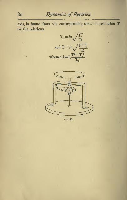
8o Dynamics of Rotation,
axis, is found from the corresponding time of oscillation Tby the relations
V E
andT=27r^/yiV R
whence 1=1,rpa rri 2
Fio. 43a.
Examples on Chapters V. and VI. 8
1
Examples for Solution.
(1) A thin heavy bar, 90 centimetres long, hangs in a horizontal
position by a light string attached to its ends, and passed over a
peg rertically above the middle of the bar at a distance of 10 centi-
metres. Find the time of a complete small oscillation in a vertical
plane containing the bar, under the action of gravity.
Ans. 1766 . . . seconds.
(2) A uniform circular disc, of 1 foot radius, weighing 20 lbs., is
pivoted on a central horizontal axis. A small weight is attached to
the rim, and the disc is observed to oscillate, under the influence of
gravity, once in 3 seconds. Find the value of the small weight.
Ans. 1*588 lbs.
(8) A bar magnet 10 centimetres long, and of square section 1
centimetre in the side, weighs 78 grams. When hung horizontally
by a fine fibre it is observed to make three complete oscillations in
80 seconds at a place where the earth's horizontal force is "18 dynes.
Find the magnetic moment of the magnet.
Ans. 202*48 . . . dyne-centimetre units.
(4) A solid cylinder of 2 centimetre radius, weighing 200 grams, is
rigidly attached with its axis vertical to the lower end of a fine wire.
If, under the influence of torsion, the cylinder make 0*5 complete
oscillations per second, find the couple required to twist it through
four complete turns. Ans. 3200 Xtt^ dyne-centimetre units.
(5) A pendulum consists of a heavy thin bar 4 ft. long, pivoted
about an axle through the upper end. Find (1) the time of swing
;
(2) the length of the equivalent simple pendulum.
Ans. (1) 1*81 seconds approximately; (2) 2*6 feet.
(6) Out of a uniform rectangular sheet of card, 24 inches x 16
inches, is cut a central circle 8 inches in diameter. The remainder is
then supported on a horizontal knife-edge at the nearest point of the
circle to a shortest side. Find the time of a complete small oscilla-
tion under the influence of gravity (a) in the plane of the card ; (6) in
a plane perpendicular thereto.
Ans. (a) 1*555 seconds; (6) 1*322 seconds.
(7) A long light spiral spring is elongated 1 inch by a force of 2
pounds, 2 inches by a force of 4 pounds. Find how many complete
small otcillntions it will make per minute with a 3 lb. weight
attached. Ann. IAS'7
F

CHAPTEE VIII.
CONSERVATION OF ANGULAR MOMENTUM.
Analogue in Rotation to Newton's Third Law of
Motion.—Newton's Third Law of Motion is the statement
that to every action there is an equal and opposite reaction.
This law is otherwise expressed in the Principle of the
Conservation of Momentum, which is the statement that
when two portions of matter act upon each other, whatever
amount of momentum is generated in any direction in the
one, an equal amount is generated in the opposite direction
in the other. So that the total amount of momentum in any
direction is unaltered by the action.
In the study of rotational motion we deal not with forces
but with torques, not with linear momenta but with angular
momenta, and the analogous statement to Newton's Third
Law is that 'no torque, with respect to any axis, can be
exerted on any portion of matter without the exertion on
some other portion of matter of an equal and opposite torque
about the same axis.
'
To deduce this as an extension of Newton's Third Law, it
is sufficient to point out that the reaction to any force being
not only equal and opposite, but also in the same straight line
as the force, must have an equal and opposite moment about
any axis.
The corresponding principle of the conservation of angular
momentum is that by no action of one portion of matter

Conservation ofAngular Momentum. 83
on another can the total amount of angular momentum, about
any fixed axis in space, be altered.
Application of the Principle in cases of Motion
round a fixed Axle.—We have seen (p. 21) that the
'angular momentum' of a rigid body rotating about a fixed
axle is the name given, by analogy with linear momentum(mr), to the product lu, and that just as a force may be
measured by the momentum it generates in a given time, so
the moment of a force may be measured by the angular
momentum it generates in a given time.
ZSt Example of the Principle.—Suppose a rigid body
A, Bay a disc whose moment of
inertia is I„ to be rotating with
angular velocity coi about a fixed
axle; and that on the same shaft
is a second disc B of moment of
inertia I„ and which we will at
first suppose to be at rest. Now,
imagine the disc B to be slid along
the shaft till some projecting point
of it begins to rub against A. This
will sot op a force of friction be-
tween the two, the moment of
which will at every instant be the
same for each, consequently as much angular momentum as is
destroyed in A will be imparted to B, so that the total
quantity of angular momentum will remain unaltered.
Ultimately the two will rotate together with the same
angular velocity Q which is given by the equation
no. 41
--ir:rt

84 Dynamics of Rotation,
If the second disc had initially an angular velocity w,, then
the equation of conservation of angular momentum gives us
(Il+ l2)Q= Iia>l +120)2,
'^''—irnr'which, it will be observed, corresponds exactly to the equation
of conservation of linear momentum in the direct impact of
inelastic bodies, viz. :
—
(7?ii+ wis)V= rrbiVi + maVj.
2nd Example.—A horizontal disc whose moment of
inertia is Ii, rotates about
a fixed vertical axis with
^ I angular velocity Wj. Imagine
a particle of any mass to be
detached from the rest, and
FIG. 45. connected with the axis by
an independent rigid bar whose mass may be neglected. At
first let the particle be rotating with the rest of the system
with the same angular velocity cuj. Now, let a horizontal
pressure, always at right angles to the rod and parallel to the
disc, be applied between them so that the rotation of the
particle is checked, and that of the remainder of the system
accelerated {e.g. by a man standing on the disc and pushing
.against the radius rod as one would push against the arm of a
lock-gate on a canal), until finally the particle is brought to
rest. By what has just been said, as much angular momentum
as is destroyed in the particle will be communicated to the
remainder of the disc, so that the total angular momentum
will remain unaltered. We may now imagine the stationary
non-rotating particle transferred to the axis, and there again
attached to the remainder of the system, without affecting

Conservation of Angular Momentum, 85
the motion of the latter. If I, is now the reduced moment
of inertia of the system, and w, its angular velocity, we have,
by what has been said,
Ii««-Ii«h
Or, we may imagine the particle, after ha^'ing been brought
to rest, pUoed at some other position on its radius, and
allowed to come into frictional contact ^^-ith the disc again,
till the two rotate together again as one rigid body. If 1$ be
now the moment of inertia of the system, we shall have
I«W,bI,Ci>,=::Ii«>1,
or •»a"'«»i)<f^
3rd Example.—Suppose that, by the application of a force
always directed towards the axis, wo
cause a portion of a rotating body to slide
along a radius so as to alter its distance
from the axis. By doing so we evidently
alter the moment of inertia of the system,
bat the angular momentum about the
axis will remain constant
For example, let a disc rotating on a
hollow shaft be provided with radial
grooves along which two equal masses
can be drawn towards the axis by means
of strings passing down the interior of the shaft It is clear
that each of the moveable masses at it is drawn along the
groove is brought into successive contact with parts of the
disc moving more slowly than itself, and must thus impart
angular momentum to them, losing as much as it imparts.
4th Example.—A mass M rotates on a smooth horisontal
no. 40.

86 Dynamics of Rotation,
plane, being fastened to a string which passes through a small
hole in the plane, and which is held by the hand. On slacken-
ing the string the mass recedes from the
^^' axis and revolves more slowly ; on tighten-
/ ing the string the mass approaches the
axis and revolves faster.
Here, again, the angular momentum Iw
will remain constant, there being no external
force with a moment about the axis to in-
crease its amount. But it is not so apparent
in this case how the increase of angular
velocity that accompanies the diminution of
moment of inertia has been brought about.
For simplicity, consider instead of a finite mass M a par-
ticle of mass m at distance r from the axis when rotating with
angular velocity a>. The moment of inertia I of the particle
is then mr^ and the angular momentum =Ia)
but ra>=?; the tangential speed\
.*. the angular momentum =mrt',
thus for the angular momentum to remain constant ?; must
incre^e exactly in proportion as r diminishes, and vke versa.
In the case in question the necessary increase in v is effected
by the resolved part of the central pull in the direction of the
motion of the particle. For the instant this pull exceeds the
value (^^) of the centripetal force necessary to keep the
particle moving in its circular path, the particle begins to be
drawn out of that path, and no longer moves at right angles
to the force, but partly in its direction, and with increasing
velocity, along a spiral path.

ConseTjation ofAngular Mo7nentum, Z^j
This increase in velocity involves an increase in the kinetic
energy of the particle equivalent to the work done by the force.
Consideration of the Kinetic Energy.—It should
be observed, in general, that if by means of forces having no
moment about the axis we alter the moment of inertia
of a system, then the kinetic energy of rotation about that
1X18 is altered in inverse proportion. For, let the initial
moment of inertia Ij become I, under the action of such forces,
then the new angular velocity by the principle of the con-
tenration of angular momentum
is CD, « (Di X i.
-Is
and the new value of the rotational energy is JlaCdS
I.
=JIXx5^
«s (original energy) x yi.
The ttadent will lee that in Example 2, p. 84, the stoppage of
the perticle with its radius rod in the way described involves
the eommunication of additional rotational energy to the disc,
and that, in Example 3, the pulling in of the cord attached
to the sliding manes commnnicated energy to the system,
thoogh not angoUr momentum.
Other Exemplifications of the Principle of the
Consenration of Angular Momentum.—(z) A juggler
standing on a spinning disc (like a music-stool) can cause his
rite of rotation to decrease or increase by simply extending
or drawing in his arms. The same thing can be done by a
akater spinning round a vortical axis with his feet close
together on well-roanded skatea.

88 Dynamics of Rotation,
(2) When water is let out of a basin by a hole in the
bottom, as the outward parts approach the centre, any rota-
tion, however slight and imperceptible it may have been at
first, generally becomes very rapid and obvious.^
(3) Thus, also, we see that any rotating mass of hot matter
which shrinks as it cools, and so brings its particles nearer to
the axis of rotation, will increase its rate of rotation as it cools.
The sun and the earth itself, and the other planets, are pro-
bably all of them cooling and shrinking, and their respective
rates of rotation, therefore, on this account increasing.
If the sun has been condensed from a very extended nebu-
lous mass, as has been supposed, a very slow rate of revolu-
tion, in its original form, would suffice to account for the
present comparatively rapid rotation of the sun (one revolu-
tion in about 25 days).
Graphical representation of Angular Momentum.—The angular momentum about any axis of any rotating
body may be completely represented by drawing a line parallel
to that axis and of a length proportional to the angular mo-
mentum in question. The
direction of the rotation is
usually indicated by the con-
vention that the line shall
be drawn in the direction in
which a right-handed screw
would advance through its
nut if turning with the same
rotation. Thus OA and OBin Figs. 48 and 49 would
represent angular momenta, as shown by the arrows. If a
^ It can be shown that other causes besides that mentioned mayalso produce the effect referred to.
no. 48.

Conservation ofAngular Momentum, 89
body having only angular momentum about an axis parallel to
and represented by OA (Fig. 50) is acted on for a time by a
couple in the same plane as the original direction of this axis,
this cannot alter the angular momentum about this axis, but
will add an angular momentum which we may represent by
OB perpendicular to OA. Then the total
angular momentum of the body must be re-
presented by the diagonal OC of the parallelo-
gram AB (Fig. 50). And in general the
amount of angular momentum existing about
any line is represented by the projection on
that line of the line representing the total
angular momentum in question.
Moment of Momentum.—The phrase ''°-^°-
* angular momentum ' is convenient only so
long as we are dealing with a single particle or with a system
of particles rigidly connected to the axis, so that each has
the same angular velocity ; when, on the other hand, we have
to consider the motions of a system of disconnected parts,
the principle of conservation of angular momentum is more
conveniently enunciated as the * conservation of momentof momentum.*By the moment of momentum at any instant of a particle
about any axis is meant the product (mtjp) of the resolved
part (mv) of the momentum in a plane perpendicular to the
axis, and the distance (p) of its direction from the axis, wthe moment of momentum of a particle may be defined and
thought of as that part of the momentum which alone is
concerned in giving rotation about the axis, multiplied by
the distance of the particle from the axis. Since the
action of one particle on another always involves the

90 Dynamics of Rotation,
simultaneous generation of equal and opposite momenta
along the line joining them (see Note on Chapter ii.), it
follows that the moments about any axis of the momenta
generated by such interaction are also equal and opposite.
Hence in any system of particles unacted on by matter out-
side there is conservation of moment of momentum, or, in
algebraical language,
2(mvp)= constant.
The moment of momentum of a particle as thus defined is
easily seen to be the same thing as its angular momentum zw.
^o For, let O be any axis perpendicular
to the plane of the paper, and P a
particle of mass m having a velocity
V inclined to the plane of the paper,
and let this velocity have a resolute v
in the plane of the paper. Let PF be
the distance traversed parallel to the
paper in a very short interval of timeFIO. 51.
pp/{di)^ then v= -^. Let^ be the length of the perpendicular ON
let fall on the direction of PP'. Then, by our definition, the
moment of momentum of the particle about the axis O is
PP'
at
The angle {dQ) swept out in this small interval of time is
theanglcPOP'=?^ (being small) =|x^=|^.*. -^rji—^idi) where w is the angular velocity,
' "*~^, .*. pv='R^(o and mvp=m'R^o)R"
1(0
i.e. the moment of momentum of the particle is the same as
its angular momentum.

Conservation ofAngular Momentum. 9
1
General Conclusion.—The student will now be prepared
to accept the conclusion that if, under any circumstances, we
observe that the forces acting on any system cause an altera-
tion in the angular momentum of that system about any given
fixed line, then we shall find that an equal and opposite altera-
tion is simultaneously produced in the angular momentum
about the same axis, of matter external to the system.
Caution.—At the same time he is reminded that it is only
in the case of a rigid body rotating about a fixed axle that we
have learned that the angular momentum about that axle is
measured by Iw. He must not conclude either that there
is no angular momentum about an axis perpendicular to
the actual axis of rotation, or that Iw will express the
angular momentum about an axis when w is only the com-
ponent angular velocity about that axis.
Ballistic Pendulum.—In Robins's ballistic pendulum,
used for detcrniiiiing the velocity of a bullet, we have an
interesting practical application of the principle of conserva-
tion of moment of momentum. The pendulum consists of a
massive block of wood rigidly attached to a fixed horizontal
axle above its centre of gravity about which it can turn
freely, the whole being Bymmetrical with respect to a vertical
plane through the centre of mass perpendicular to the axle.
The bullet is fired horizontally into the wood in a plane
perpendicular to the axle, and remains embedded in the
mass, penetration ceasing before the pendulum has moved
appreciably. The amplitude of swing imparted to the pen-
dulum is observed, and from this the velocity of the bullet

92 Dynamics ofRotation,
before impact is easily deduced. Let I be the moment
of inertia of the pendulum alone about the axle, M its
mass, (Z the distance of its centre of gravity from the axis.
Let m be the mass of the bullet and r its distance from the
axis when penetration ceases, and let Q be the angle through
which the pendulum swings to one side.
Then the angular velocity w at its lowest point is found by
writing
Kinetic energy of pendulum ^ r work done against gravity
and embedded bullet at [- = ^ in lifting through
lowest point, j (. angle ^,
Pa>2+Jmr2(o2=:M^(^(l-cos^)+w^r(l-cos^),
an equation which gives us o>.
Now, let V be the velocity of the bullet before impact that
we require to find, and I the shortest distance from the axis
to the line of fire. Then writing
moment of momentum about^_ rangular momentum about
axis before impact, / I axis after impact,
we have
which gives us v.
The student should observe that we apply the principle of
conservation of energy only to the frictionless swinging of the
pendulum, as a convenient way of deducing its velocity at its
lowest point. Of the original energy of the bullet the greater
part is dissipated as heat inside the wood.
In order to avoid a damaging shock to the axle, the bullet
would, in practice, be fired along a line passing through the
centre of percussion, which, as we shall see (p. 124), lies at
a distance from the axis equal to the length of the equivalent
simple pendulum.

Examples on Chapter VII
L
93
Examples.
(1) A horizontal disc, 8 inches in diameter, weighing 8 lbs., spins
without appreciable friction at a rate of 10 turns per second about
a thin Tertical axle, over which is dropped a sphere of the same
weight and 5 inches in diameter. After a few moments of slipping
the two rotate together. Find the common angular velocity of the
two, and also the amount of heat generated in the rubbing together
of the two (taking 772 foot-pounds of work as equivalent to one unit
of heat). Ans. (i) 7*619 turns per sec.
„ (ii) -008456
(2) A uniform sphere, 8 inches in radius, rotates without friction
about a vertical axis. A small piece of putty weighing 2 oz. is
projected directly on to its surface in latitude 30° on the sphere and
there sticks, and the rate of spin is observed to be thereby reduced
by x^. Find the moment of inertia of the sphere, and thence its
pecific gravity. Ans. (i) 7J oz.-foot* units.
„ (ii)-0332.
(8) Assuming that the N.E. trade-winds would be N. winds but
for the earth's rotation, examine the suggestion that a windmill which
is worked by the easterly component of such a wind is driven at the
expense of the earth's rotation.
(4) A boy leaps radially from a rapidly revolving round-about on
to a neighbouring one at rest, and to which he clings. Find the
effect on the second, supposing it to be unimpeded by friction, andthat the boy reaches it along a radius.
(6) A wheel on a frictionless axle has its circumference pressed
agaiost a travelling band moving at a speed which is maintained
constant. Prove that when clipping has ceased as much energy will
have been lost in heat as has been imparted to the wheel.
(e) Find the velocity of a bullet fired into a ballistic pendulum from
the following data :
—
The moment of inertia of the pendulum is 200 Ib.-foof units,
and it weighs 20 lbs. The distance from the axis of its centre of
gravity is 3 feet, and of the horizontal line of fire is ^ feet ; the
bullet penetrates as far as the plane containing the axis and centre of
msM and weighs 2 oz. The cosine of the observed swing is \.
Ans. 050'.39 feet per seo.
(taking ^==32*2.)

CHAPTEE IX.
ON THE KINEMATICAL AND DYNAMICAL PROPERTIES OF THE
CENTRE OF MASS.
Evidence of tjje existence for a Rigid Body of a
point possessing peculiar dynamical relations.—
Suppose a single external force to be applied to a rigid body
previously at rest and perfectly free to
move' in any manner. The student will
prepared to admit that, in accordance
with Newton's Second Law of Motion,
the body will experience an acceleration
proportional directly to the force and
inversely to its mass, and that it will
begin to advance in the direction of the
applied force. But Newton's Law does not tell us explicitly
whether the body will behave differently according to the
position of the point at which we apply the force, always
assuming it to be in the same direction.
Now, common experience teaches us that
there is a difference. If, for example, the
body be of uniform material, and we apply
the force near to one edge, as in the second
figure, the body begins to turn, while if weno. 53.
apply the force at the opposite edge, the
body will turn in the opposite direction. It is always possible,
however, to find a point through which, if the force be ap-
pre
r^ he
I I ^ wit
FIO. 52.

Properties of the Centre of Mass, 95
plied, the body will advance without turning. The student
should observe that if, when the force was applied at one
edge of the body, as in Fig. 2, the body advanced without
turning, precisely as we may suppose it to have done in
Fig. 1, this would not involve any deviation from Newton's
Law applied to the body as a whole^ for the force would still
be producing the same mass-acceleration in its own direction.
It is evidently important to know under what circum-
stances a body will turn, and under what circumstances it will
not.
The physical nature of the problem will become clearer in
the light of a few simple experiments.
Experiment 1.—Let any convenient rigid body, such as a walking-
stick, a hammer, or say a straight rod conveniently weighted at one
end, be held vertically by one hand and then allowed to fall, and
while falling let the observer strike it a smart horizontal blow, and
observe whether this causes it to turn, and which way round ; it
is easy, after a few trials, to find a point at which, if the rod be struck,
it will not turn. If struck at any other point it does turn. The ex-
periment is a partial realisation of that just alluded to.
Bzpcrlmaat S.— It is instructive to make the experiment in another
way. Let a smooth stone of any shape, resting loosely on smooth
hard ice, be poked with a stick. It will be found easy to poke the
•tone either so that it shall turn, or so that it shall not turn, and if
the direction of the thrusts which move the stone without rotation be
noticed, it will be found that the vertical pUmes containing these
directions intersect in a common line. If, now, the stone be turned
on its side and the experiments be repeated, a second such line can
be found intersecting the first. The intersection gives a point through
which it will be found that any force must pass which will cause
motion without taming.
lipwlBttnl t.—With A li^'lii '»i'j'"t, Mirli as ;i flat piccc of paper or
card of any shape, the expnuncni niay \>c m.ulo hy laying it, with a
very fine thread attached, on the surface of a horizontal mirror dusted
over with lycopodiom powder to diminish friction, and then tugging

96 Dynamics of Rotation.
at the thread ; the image of the thread in the mirror aids in the
alignment. The thread is then attached at a different place, and a
second line on the paper is obtained.
If a body, in which the position of the point having these
peculiar properties has been determined by any of the
methods described, be examined to find the Centre of Gravity,
it will be found that within the limits of experimental error
the two points coincide. This result may be confirmed by
the two following experiments.
Experiment 4.—Let a rigid body of any shape whatever be allowed
to fall freely from rest. It will be observed that, in whatever position
the body may have been held, it falls without turning (so long at any
rate as the disturbing eflfect of air friction can be neglected). In this
case we know that the body is, in every position, acted on by a
system of forces (the weights of the respective particles) whose resul-
tant passes through the centre of gravity.
Experiment 5.—When a body hangs at rest by a string, the direc-
tion of the string passes through the centre of gravity. If the string
be pulled either gradually or with a sudden jerk, the body moves
upward with a corresponding acceleration, but again without turning.
This is a very accurate proof of the coincidence of the two points.
We now pass to another remarkable dynamical property,
which may be enunciated as follows :
—
' If a couple be applied to a non-rotating rigid body that is
perfectly free to move in any manner^ then the body mil begin to
rotate about an axis passing through a point not distinguishable
from the centre of gravity.'
This very important property is one which the student
should take every opportunity of bringing home to himself.
If a uniform bar, AB,
X'^ o ^B free to move in any man-
A ^^ ner, be acted on by a couple
no. 64. whose forces are applied

Properties of the Centre of Mass. 97
as indicated, each at the same distance from the centre of
mass G, then it is easy to believe that the bar will begin to
turn about G. But if one force be applied at A and the other
TVX. 55. no. 66.
at G itself, as in Fig. 55, or between A and G, as in Fig. 56,
then it is by no means so obvious that G will be the tuining
point. The matter may be brought to the test of experiment
in the manner indicated in the following figure.
V„
^L^=.g-"BL."L|g. l§»Tr=
!
T\Q. 57.
Experiment 6.—A Magnet NS lies horizontally on a square-cut
Mock of wood, being suitably counterpoised by weights of brass or
lead, so that the wood can float ns shown in a large vessel of still
water. The whole is turned so that the magnet lies magnetic east
and west, and then released, when it will bo observed that the centre
of gravity G remains * vertically under a fixed point P as the whole
> The centre of gravity must, for hydrostatic reasons, be situated
in the same vertical line as the centre of figure of the submerged part
of the block.
O
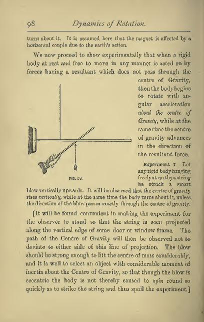
98 Dynarnics of Rotation,
turns about it. It is assumed here that the magnet is aflfected by a
horizontal couple due to the earth's action.
We now proceed to show experimentally that when a rigid
body at rest and free to move in any manner is acted on by
forces having a resultant which does not pass through the
centre of Gravity,
then the body begins
to rotate with an-
gular acceleration
about the centre of
Gravity, while at the
same time the centre
of gravity advances
in the direction of
the resultant force.
Experiment 7.—Let
any rigid body hanging
FIG. 53. freelyat restby a string
be struck a smart
blow vertically upwards. It will be observed that the centre of gravity
rises vertically, while at the same time the body turns about it, unless
the direction of the blow passes exactly through the centre of gravity.
[It will be found convenient in making the experiment for
the observer to stand so that the string is seen projected
along the vertical edge of some door or window frame. The
path of the Centre of Gravity will then be observed not to
deviate to either side of this line of projection. The blow
should be strong enough to lift the centre of mass considerably,
and it is well to select an object with considerable moment of
inertia about the Centre of Gravity, so that though the blow is
eccentric the body is not thereby caused to spin round so
quickly as to strike the string and thus spoil the experiment.]

Properties of the Centre of Mass. 99
We have now quoted direct experimental evidence of the
existence in the case of rigid bodies of a point having peculiar
dynamical relations to the body, and have seen that we are
unable experimentally to distinguish the position of this
point from that of the centre of gravity. But this is no proof
that the two points actually coincide. Our experiments have
not been such as to enable us to decide that the points are not
in every case separated by y^\j^ inch, or even by-j-J^^
inch.
We shall now proceed to prove that the point which has
the dynamical relations referred to is that known as the
Centre of Mass, and defined by the following relation.
Let 77i„ 7»„ m„ ... be the masses of the constituent particles
of any body or system of particles; and let iCi, x„ a:,, . . . be
their respective distances from any plane, then the distance
X of the centre of mass from that plane is given by the
relation a;=
- 2(?7w;)or a;= X^—-
That the centre of mass whose position is thus defined
coincides experimentally with the centre of gravity, follows,
as was pointed out in the note on p. 38, from the experimental
fact, for which no explanation has yet been discovered, that
the mass or inertia of different bodies is proportional to their
weight, i.e. to the force with which the earth pulls them.
Our method of procedure will be, first formally to enunciate
and prove certain very useful but purely kinematical pro-
perties of the Centre of Mass, and then to give the theoretical
proof that it possesses djmamical properties, of which we have
selected special examples for direct experimental demon-
stration.

lOO Dyna7nics of Rotation.
By the student who has followed the above account of the
experimental phenomena, the physical meaning of these pro-
positions will be easily perceived and their practical import-
ance realised, even though the analytical proofs now to be
given may be found a little difficult to follow or recollect.
Proposition I.—(Kinematical.) On the displacement of
the centre of mass.
If the particles of a system are displaced from their initial
positions in any directions, then the displacement d experienced by
the centre of mass of the system in any one chosen direction is con-
nected with the resolved displacements di, da, d^, . . . of the
respective particles in the same direction by the relation
d=^'^1^1 +^2^2+ .... -^mndn
mi+Wa-h .... +w„
^ ^md)or d= 2m
Proof.—For, let any plane of reference be chosen, perpen-
dicular to the direction of resolution, and let x be the distance
of the centre of mass from this plane before the displacements,
of its distance after the displacements.
Then x= L and x'=—^zm zm^{mx) ^(md)
~ 2m "^ 2m
-^ - .- l.{md)
" ^-^=^=-2^' Q.E.D.
If 2(mfZ)=o, then d=Oy i.e. if, on the whole, there is no
mass-displacement in any given direction, then there is
no displacement of the centre of mass in that direction.
Properties of the Centre of Mass, loi
Definitions.—If a rigid body turns while its centre of
mass remains stationary, we call the motion one of pure
rotation.
When, on the other hand, the centre of mass moves, then
wc say that there is a motion of translation.
Proposition II.— (Kinematical.) On the velocity of
the centre of mass of a system. If v^y v„ v, ... be the
respective velocities in any given direction at any instant of the
particles of masses m„ fw„ m,, «/c., of any system^ then the
velocity v of their centre of mass in the same direction is given by
the relation
This follows at once from the fact that the velocities are
measured by, and are therefore numerically equal to, the
displacements they would produce in unit time.
Proposition III.—(Kinematical.) On the acceleration of
the centre of mass. If Oi^ a^y . , , be the accelerations in any
given direction^ and at the same instant of the respective particles
of nuusei niu m^ . . . of a system, then tfie acceleration a
of their centre of mass in the same direction at that instant, is
given by the reUUifm
-¥This follows from Proposition II., for the accelerations are
measured by, and arc therefore numerically equal to, the
velocities they would generate in unit time.
I02 Dynainics of Rotation,
Summary.—These three propositions may be conveniently
summed up in the following enunciation.
/- mass-displacements \
The sumofthe resolutes in anydirectionofthe < momenta >
\ mass-accelerations )
of the particles of any system is equal to the total mass of the
r displacement \
system multiplied by the < velocity V , in the same directum,
\ acceleration )
of the centre of mass.
Corresponding to these three Propositions are
three others referring to the sum of the moments about any
r mass-displacements \
axis of the-( momenta > of the particles of a system,
V mass-accelerations /
and which may be enunciated as follows :
—
^ The algebraic sum of the moments about any given fixed
r mass-atspiacements \
axis of the < momenta > of the particles of any system
\ mass-accelerations )
is equal to the sum of the moments of the same quantities about a
parallel axis through the centre of mass^ plus the moment about
the given axis
C displacement \
of the^ velocity Vof the centre of mass^ multiplied by tlie
^ acceleration J
mass of the whole system.
Since the moment of the mass-displacement of a particle has
no special physical significance, we will begin at the other
end of the chain and give the proof for the mass-accelerations.
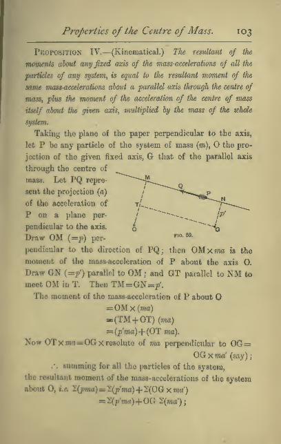
Properties of the Centre of Mass, 103
Proposition IV.—(Kinematical.) The resvUtant of the
momerUs about any fixed axis of the mass-accelerations of all the
particles of any system, is equal to the resultant moment of the
same mass-accelerations about a parallel axis through the centre of
mass, plus the moment of the acceleration of the centre of mass
itself about the given axis, multiplied by the mass of the whole
system.
Taking the plane of the paper perpendicular to the axis,
let P be any particle of the system of mass (m), the pro-
jection of the given fixed axis, G that of the parallel axis
through the centre of
mass. Let PQ repre-
sent the projection (a)
of the acceleration of
P on a plane per-
pendicular to the axis.
Draw OM (=p) per-"°'^^-
pendicular to the direction of PQ; then OM xma is the
moment of the mass-acceleration of P about the axis 0.
Draw ON (=p') parallel to OM; and GT parallel to NM to
meet OM in T. Then TM=GN=/.The moment of the mass-acceleration of P about
=OMx(ma):(TM + 0T)(7na)
= (p'ma)+{OT: ma).
Now orxwia=OGx resolute of ma perpendicular to 0G=OG xma' (say);
.'. summing for all the particles of the system,
the resultant moment of the mass-accelerations of the system
about 0, •.«. 2(;witt)=iX;?'fna)+2(00 xma')
^l(p'ma)+00 1{ma');
I04 Dynamics of Rotation.
but if a! be the resolute of the acceleration of the centre of
mass, perpendicular to OG, then, by Proposition III.,
2(ma')=a'277i.
80 that the proposition is proved.
Similarly we could have proved that The angular momentum
of any system of particles about any fixed axis is equal to the
angular momentum about a parallel axis through the centre of
masSf plus the angular momentum which the system would
have about the given axis, if collected at the centre of mass and
moving with it.
Proposition V.—(Dynamical.) On the motion of the
centre of mass of a body under the action of external forces.
We shall now show that
The acceleration in any given direction of the centre of mass of
a material system
algebraic sum of the resolutes in that direction of the externalforces—mass of the whole system
For, by Newton's Second Law of Motion (see note on
Chapter IL),
(the algebraic sum of the ex-\ _ /the algebraic sum of the mass-\
ternal forces^ ) \ acceleration^^ J
2E=2(?7ia);
but by III. 'Z(ma)=a'2m;
.-. 2E=a2w,- 2E
which is what we had to prove.

Properties of tlie Centre of Mass. 105
This result is quite independent of the manner in which the
external forces are applied, and shows that when the forces
are constant and have a resultant that does not pass through
the centre of mass (see Fig. 53), the centre of mass will,
nevertheless, move with uniform acceleration in a straight
line, so that if the body turns it must he about an axis through
the centre of mass.
Proposition VI.—(Dynamical.) The application of a
couple to a rigid body at rest and free to move in any manner^ can
only cause rotation about some axis through the centre of mass.
For, by Proposition V.,
2EAcceleration of centre of mass=^=—
,
zmbut in the case of a couple 2E=0 for every direction, so that
the centre of mass has no acceleration due to the couple,
which, therefore (if the body were moving), could only add
rotation to the existing motion of translation.
Proposition VIL—(Dynamical.) WTicn any system of
forces is applied to a free rigid hody^ the e^ect on tJie rotation
about any axis fixed in direction^ passing through the Centre of
Mass and moving with t/, is independent of the motion of the Centre
of Mass.
For, by the note on Chapter II., p. 32,
- (momenU of the mass-l R,gu,t^t moment of thoaccelerations about any V - ^^^^^^ j.^^^^^
axis fixed in space) ^
or '2(pma)=L
but, by Proposition IV. (see Fig. 69, p. 103),
^pma)=^p'ma)+0G 2(ma')
.-. l{p'ma)+OQ l{ma')='L

io6 Dynamics of Rotation.
If, now, the centre of mass be, at the instant under considera-
tion, passing through the fixed axis in question (which is
equivalent to the axis passing through the Centre of Mass
and moving with it), OG=0 and the second term vanishes
and 2(r'm(i)=L,
i.e. the sum of the moments of the mass-accelerations about
such a moving axis = resultant moment of the external forces,
precisely as if there had been no motion of the Centre of
Mass. This proposition justifies the independent treat-
ment of rotation and translation under the influence
of external forces.
On the direction of the Axis through the Centre
of Mass, about which a couple causes a free Rigid
Body to turn.—Caution.—The reader might be at first
disposed to think that rotation would take place about an
axis perpendicular to the plane of the applied couple, especially
as the experiments quoted do not reveal the contrary ; but
it should be observed that the experiment of the floating
magnet was not such as would exhibit satisfactorily rotation
about any but a vertical axis.
It is not difficult to show that rotation will not in general
begin about the axis of
the couple. To fix the
ideas, let us imagine
a body composed of
three heavy bars cross-
ing each other at right-
angles, at the same
point 0, which is the
centre of mass of the
whole system, and letno. 60.

Properties of the Centre of Mass, 107
the bar AB be much longer and heavier than either of the
other two CD and EF, and let this massive system be
embedded in surrounding matter whose mass may be
neglected in comparison.
It is evident that the moment of inertia of such a system is
much less about AB than about CD or EF, or that it will be
easier to rotate the body about AB than about CD or EF.
Hence, if a couple be applied, say by means of a force through
the centre of mass along EF, and an equal and opposite force
at some point P on the bisector of the angle DOB, then this
latter force will have equal resolved moments about CD and
about AB. But rotation will begin to be generated more
rapidly about the direction of AB than about that of CD,
and the resulting axis of initial rotation will lie nearer to
AB than to CD, and will not be perpendicular to the plane
of the couple. In fact, the rods EF and CD will begin to turn
about the original direction of AB, considered as fixed in
space, while at the same time the rod AB will begin to rotate
about the axis CD, considered as fixed, but with a more slowly
increasing velocity. We shall return to this point again in
Chapter xii.
Total Kinetic Energy of a Rigid Body.—When &
body rotates with angular velocity (w) about the centre o
mass, while this has a velocity (t>), we can, by a force through
the centre of mass destroy the kinetic energy of translation
(JMt;*) leaving that of rotation (JIcu') unaltered. Thus,
the total kinetic energy=iMv'-f JIw*.
In the examples that follow on p. 110, this consideration
often gives the readiest mode of solution.

io8 Dynamics of Rotation,
Examples.
(1) Tv3o masses M and m, of which M is the greater^ hang at
the ends of a weightless cord over a smooth horizontal peg, and move
under the action of gravity ; to find the a,cceleration of their centre of
mass and the upward pressure of the peg.
Taking the downward direction as + ve, the acceleration of M is
M -
m
...I.M. xi.-i. -J ^ :- _M-m^ M +m
— while that of m is -g ^,M +m Hence substituting in the
general expression for the acceleration of the centre of mass,
^i,., ^=^ we have
5_My(M m)-mg'(M-m) (M-m)(M + m)2 ^(M + m)2
The total external force which produces this acceleration is the sumof the weights - the push P of the peg
;
/. (M + m)sr- P= (M + m)grP'''{M +mf
'(M+m)2
:^-f—^ absolute units of force.M+m
(2) A uniform solid sphere rolls without slipping down a plane
inclined at an angle 6 with the horizontal ; to find the acceleration ofits centre and the tangential force due to the friction of the plane.
It is evident that
if there were no
friction the sphere
would slide and not
roll, and therefore
that the accelera-
tion (a) of the cen-
tre C, which wewish to'ftnd is due
to a total force mgsin ^ - P parallel to
ria. 60a.
Properties of the Centre of Mass, 109
the plane, where P is the friction.
^_m7sm—-—^ ^]^gj.g ^ _ tjjg niass of the sphere,mp= ^8m5-- . . . . (i)
Now, the moment of the force (P) with reference to a horizontal axis
through C is Pr, and, therefore, calling the angular acceleration of
the sphere A, and its radius of gyration i,
Pr=AI=AxmJk2 . (ii)
P^A^2* * m r
.'. substituting in (i)
a=a8ind-—
.
r
Now, since the sphere is at any instant turning about the point of
contact with the plane, we have w =— and A= - (iii)
.*. substituting in the equation, we get
a=g sin 0--^r*
—gr sin -5—r.
In the case of a sphere fc^= 1 =-^r*6 6
.-. a = g&inBx~-.7
Hence, equating the total force to the roass-acceleration down the
plane,
TW^sin^-P—Tn^sindx
2P==-mj7sind.
[This question might also have been solved f&x)m the principle of
the Oonsorvation of Energy.]
1 1o Dynamics of Rotation
.
Examples for Solution.
(1). Show that when a coin rolls on its edge in one plane, one-third
of its whole kinetic energy is rotational.
(2) Show that when a hoop rolls in a vertical plane, one-half of its
kinetic energy is rotational.
(3) Show that when a uniform sphere rolls with its centre moving
along a straight path, ^ of its kinetic energy is rotational.
(4) Find the time required for a uniform thin spherical shell to
roll from rest 12 feet down a plane inclined to the horizontal at a
slope of 1 in 50. Ans. 8 seconds (nearly).
(5) You are given two spheres externally similar and of equal
weights, but one is a shell of heavy material and the other a solid
sphere of lighter material. How can you easily distinguish between
them?
(6) A uniform circular disc, half an inch thick and 12 inches in
radius, has a projecting axle of the same material half an inch in
diameter and 4 inches long. The ends of this axle rest upon two
parallel strips of wood inclined at a slope of 1 in 40, the lower part
of the disc hanging free between the two. The disc is observed to
roll through 12 inches in 53*45 seconds. Deduce the value of gr correct
to 4 significant figures. Ans. g = 32'l9f.s.s.
(7) What mass could be raised through a space of 30 feet in 6
seconds by a weight of 50 lbs., hanging from the end of a cord passing
round a fixed and a moveable pulley, each pulley being in the form of
a disc and weighing 1 lb. Ans. 84*02 lbs.
Insli'uctions.—Let M be the mass required. Its final velocity at theOQ
end of the six seconds will be twice the mean velocity, i.e. 2 x '^ f.s.
= 10/.«. From this we know all the other velocities, both linear andangular—taking the radius of each pulley to be r. Equate the sum of
the kinetic energies to the work done by the earth's pull. Rememberthat the fixed pulley will rotate twice as fast as the moveable one.
(8) A uniform cylinder of radius r, spinning with angular velocity
CO, about its axis, is gently laid, with that axis horizontal, on a hori-
zontal table with which its co-efficient of friction is /x. Prove that it
will skid for a time-I^ and then roll with uniform velocity—
.
3fig 3
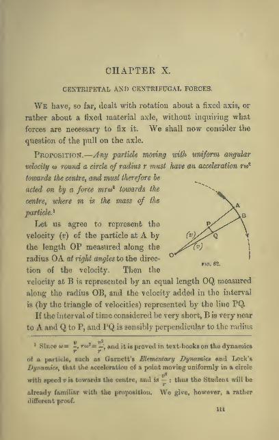
CHAPTEE X.
CENTRIPETAL AND CENTRIFUGAL FORCES.
We have, so far, dealt with rotation about a fixed axis, or
rather about a fixed material axle, without inquiring what
forces are necessary to fix it. We shall now consider the
question of the pull on the axle.
Proposition.—Any particle moving with uniform angular
velocity w rouiid a circle of radius r must have an acceleration rw*
towards the centre^ and must therefore he
acted on by a force mro)* towards the"'^-
centre, where m is the mass of the ^\.aparticle.'^ ^/\b
Let us agree to represent the y<^^y'^^^^\
velocity (r) of the particle at A by (""1/^^^ \the length OP measured along the ^^v^') \
radius OA aX right angles to the direc- '•^ ^ no. 62.
tion of the velocity. Then the
velocity at B is represented by an equal length OQ measured
along the radius OB, and the velocity added in the interval
is (by the triangle of velocities) represented by the lino PQ.
If the interval of time considered be very short, B is very near
to A and Q to P, and PQ is sensibly perpendicular to the radius
* Sinco «= -, rw'rr—•, and it is proved in text-books on the dynamics
of a particle, such as Gamett's EHemtrUary Dynamics and Lock's
Dynamics, that the acceleration of a point moving uniformly in a circle
with speed v is towards the centre, and is — : thus the Student will be
already familiar with the proposition. We give, however, a rather
different proof.
Ill
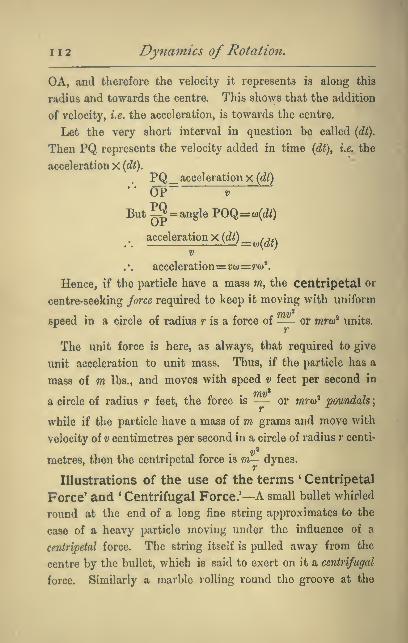
112 Dynamics of Rotation.
OA, and therefore the velocity it represents is along this
radius and towards the centre. This shows that the addition
of velocity, i.e. the acceleration, is towards the centre.
Let the very short interval in question be called {Ai).
Then PQ represents the velocity added in time {dt\ i.e, the
acceleration X (dt).
PQ_ acceleration x (dt)•*' OP V
But^= angle TOq= w(dt)
. acceleration x(6?Q_ /7.v
V
acceleration= ?;a>= ?•w^
Hence, if the particle have a mass m, the centripetal or
centre-seeking force required to keep it moving with uniform
speed in a circle of radius r is a force of— or mro)^ units.
The unit force is here, as always, that required to give
unit acceleration to unit mass. Thus, if the particle has a
mass of m lbs., and moves with speed v feet per second in
a circle of radius r feet, the force is — or mra)^ poundalsj
while if the particle have a mass of m grams and move with
velocity of v centimetres per second in a circle of radius r centi-
metres, then the centripetal force is m— dynes.
Illustrations of the use of the terms * Centripetal
Force' and * Centrifugal Force.'—A small bullet whirled
round at the end of a long fine string approximates to the
case of a heavy particle moving under the influence of a
centripetal force. The string itself is pulled away from the
centre by the bullet, which is said to exert on it a centrifugal
force. Similarly a marble rolling round the groove at the

Centripetal and Centrifugal Forces, 113
rim of a solitaire-board is kept in its circular path by the
centripetal pressure exerted by the raised rim. The rim, on
the other hand, experiences an equal and opposite centrifugal
push exerted on it by the marble.
In fact, a particle of matter can only be constrained to
move with uniform angular velocity in a circle by a centri-
petal force exerted on it by other matter, and the equal and
opposite reaction exerted by the body in question is in most
cases a centrifugal force. Thus, when two spheres attached
to the ends of a fine string rotate round their common
centre of gravity on a smooth table, each exerts on the string
a centrifugal force. In the case, however, of two heavenly
bodies, such as the earth and moon, rotating under the influ-
ence of their mutual attraction about their common centre of
gravity, the force that each exerts on the other is centripetal.
We cannot in this case perceive anything corresponding to the
connecting string or to the external rim.
Centripetal Forces in a Rotating Rigid Body.—When we have to deal, not with a single particle, but with a
rigid body rotating with angular velocity w, and of which the
particles are at different distances, r„ r„ r„ etc., from the
axis, it becomes necessary to find the resultant of the forces
{.myT^io^), (7n,r,(u"), etc., on the several particles.
Rigid Lamina.—We take first the case of a rigid lamina
of mass M turning about an axle perpendicular to its plane.
Here all the forces lie in one plane, and it is easily shown
that the resultant required is a single force, through the centre
of mass of the lamina, and equal to MRo>', where R is the
distance from the axis to the centre of mass;[and MR(u*,
Y«again, is equal to M-^ , where V is the speed of the centre
of mass in its circular path].
H

114 Dynamics of Rotation.
This may be shown at once from the following well-known
proposition in Statics: *If two forces be represented in
FIO. 63. FIO. 64.
that the ratio 7==^=
magnitude and direction by m times OA and n times OB,
then their resultant is represented in magnitude and direc-
tion by (m+w) times OC,
C being a point which
divides the line AB, so
AC __^ ,
CB'm*•B (For proof see Greave's
Statics, p. 18.) For let
A and B be any two
particles of the lamina, and let their masses be m and Ti,
then the force along AO is mw^AO, and that along OB is
nco'OB; therefore, by the proposition quoted, the resultant
force is (m+7i)a)'C0, and passes through 0, which, since it
divides the distance AB inversely as the masses, is the centre
of mass and centre of gravity of the two particles. This
resultant may next be combined with the force on a third
particle of the rigid system, and so on till all are included.

Centripetal and Centrifugal Forces. 1 1
5
Extension to Solids of a certain t3rpe.—By piling
up laminae whose centres of gravity all lie on the same
no. an fin. 70.
line parallel to the axis, as indicated in the diagrams (Figs.
66-70), wo may build up solids of great variety of shape, and

1 1
6
Dynamics of Rotation.
by then combining resultants on the several laminae, we see
that in order to keep the body rotating with uniform angular
velocity, we require only a single force passing through its
centre of gravity, and directed towards the axis and equal to
MR(i)', where M is the mass of the whole body.
The requisite force might, in such a case, be obtained by
connecting the centre of gravity of the body to the axis by a
string. The axis would then experience a pull MRw', which
changes in direction as the body rotates.
If the axis passes through the centres of mass of
all such laminae, then R=0, and the force disappears, and
the axis is unstrained. It is often of high importance that
the rapidly rotating parts of any machinery shall be accu-
rately centred, so that the strains and consequent wear of
the axle may be avoided.
Convenient Dynamical Artifice. — It should be
observed that the single force applied at the centre of mass
would not supply the requisite centripetal pressure to the
individual particles elsewhere if the body were not rigid.
If, for example, the cylinder AB rotating as indicated
about 00' consisted of loose smooth particles of shot or
sand, it would be necessary to enclose these in a rigid case
in order that the single force applied at G should maintain
equilibrium. The particles between G and A would press
against each other and against the case, and tend to turn it
round one way, while those between G and B would tend, by
their centrifugal pressure, to turn it the other way. Now, it is
very convenient in dealing with problems involving the con-
sideration of centripetal forces to treat the question as one

Centripetal and Centrifugal Forces. 11
7
of the equilibrium of a case or shell, which we may regard as
possessing rigidity,
but no appreciable
mass, and which
is honey - combed
throughout by min-
utecells,within which
the massive particles /" \q (mrw^)
may be conceived to ^^
lie as loose cores
exerting on the cell-
walls centrifugal
pressures, whose re-
sultant must be bal- cy
anced by some ex-no. 71.
temal force, or system of forces, if the equilibrium is to be
maintained. By the aid of this artifice, for the use of which
the student will find plenty of scope in the examples that are
given in the text-books of Garnett and Lock, already referred
to, the problem of finding the forces necessary to maintain
equilibrium may be dealt with as one in Statics.
Centrifugal Couples.—Let us now, using the method of
this artifice, consider the revolution about the axis 00' of a
thin uniform rod AB. So long as the rod is parallel to the
axis, a single force at its centre of gravity G suffices for equi-
librium; but if the rod be tilted towards the axis, as shown in
the figure, then it is evident that the centrifugal forces on the
part AG are diminished, while those on GB are equally in-
creased (the force being everywhere proportional to the dis-
tance from the axis) ; hence the resultant now to be sought

ii8 Dyna^nics of Rotation.
is that of the system indicated by the arrows in the figure,
which is easily seen to be, as before,
a single force of magnitude MRw",
but which now passes through a
point in the rod between G and B,
and therefore has a moment about
G. Such a force is equivalent to
an equal parallel force through G,
together with a couple in a plane
containing G and the axis. Such
a couple is called a Centrifugal
Couple. It is evident that though,
when the rod is parallel to the axis
(attached to it, for example, by a
string to the centre of mass),
there is no centrifugal couple, yet the
equilibrium, though it exists, is un-
stable, for the slightest tilt of either end of the rod towards
the axis will produce a centrifugal couple tending to increase
the tilt. It is for this reason that a stick whirled by a cord
attached to its centre of mass always tends to set itself
radially.
no. 72.
Centrifugal Couple in a body of any shape.—With a
body of any shape whatever rotating about a fixed axis, the
same conclusion is amved at, viz., that the centrifu^l forces
(due to the interior mass on the outside visible shell) are
equivalent always to a single force MRw'' applied at the centre
of mass of the body, and a couple in a plane parallel to the
axis ; but the axis of this couple will not, except in special
cases, be perpendicular to the plane containing the centre of
gravity and the axis of rotation.

Centripetal and Centrifugal Forces, 119
This result may be reached by taking, first, any two par-
ticles of the body, such as A and B in the diagram, of masses
m and n respectively, and
showing that the centrifugal
forces "p and 5 exerted by each
are equivalent to two forces
along CA' and CB' (the direc-
tions of the projections of pand g on a plane perpendicular
to the axis and containing the
centre of mass of the two
particles), together with the
two couples /?p' and gg'. Then
the two coplanar forces along
CA' and CB' have, as before
(see p. 114), a resultant
(/;i-f-n)w'CG, while the two
couples combine into a single
resultant couple in a plane parallel to or containing the axis
of rotation but not parallel to CG unless m and n are equal.
In this way, taking all the particles in turn, we arrive at the
single force through the centre of mass of the whole and a
single couple.
Centrifugal Couples vanish when the rotation is
about a Principal Axis.—It is obvious that in the case of
a thin rod (see Fig. 72) there is no centrifugal couple when
the rod is either parallel or perpendicular to the axis of rota-
tion, which is then a principal axis (or parallel to a principal
axis), and it is easy to show that for a rigid body of any
shape the centrifugal couples vanish when the rotation is
about a principal axis.

I20 Dynamics of Rotation.
Fio. 78a.
iVjo/.—Let us fix our attention on any particle P of a body
which rotates with uniform positive angular velocity Wy, about
a fixed axis Oy passing through the
centre of mass of the body. Let
Ox and Oz be any two rectangular
axes perpendicular to Oy. The
centripetal force on the particle is
always equal to —mroiy^ (negative
in sign because it tends to decrease
r, see Fig. 73a), and its component
-3 parallel to Ox is —mx(t)y^y and this
changes the value of the momentum
of the particle perpendicular to the
plane yz. The moment about Oz
of this component of the centripetal force is —(Oy'mxy and
measures the rate at which angular momentum is being
generated about Oz. The sum of the moments of such com-
ponents for all the particles of the body is —(Oy^2mxy, and this
with its sign changed, or (oj^lmxy, is the measure of the centri-
fugal couple about 0^;. Now 'Zmxy vanishes when either x or
y is a principal axis of the body (see pp. 59 and 60). Hence
there is no centrifugal couple when the body rotates about a
principal axis.
It follows that a rigid body rotating about a principal axis,
and unacted on by any external torque, will rotate in equili-
brium without the necessity of being tied to the axis. But in
the case of bodies which have the moments of inertia about
two of the principal axes equal the equilibrium, as we have
seen, will not be stable unless the axis of rotation is the axis
of greatest moment.

Centripetal and Cc7itrif2igal Forces. 1 2
1
Importance of properly shaping the parts of
machinery intended to rotate rapidly.—In connection
with this dynamical property of principal axes, the student
will now recognise the importance of shaping and balancing
the rotating parts of machinery, so that not merely shall the
axis of rotation pass through the centre of mass, but it shall
also be a principal aziSy since in this way only can injurious
stresses on the axle be completely avoided.
Equimomental bodies similarly rotating have
equal and similar centrifugal couples.—Proof.—Let
2^i> yi> ^i be any three rectangular axes of the one body
(1), and x^ y^ z^ the corresponding axes of the other (2), and
let A', B', O be the respective moments of inertia about these
axes. Then about any other axis, in the plane xy making
any angle a with (a;), /? (= 90°— a) with (y), and 7 (= 90°)
with {z)y the moment of inertia of (1) is (as we see by refer-
ring to p. 60),
A' cos' aH- B' cos' /?— 227nx,yi, cos a cos j8,
while that of (2) about a corresponding axis is
A' cos' a+B' cos' fi— 21mxtyt cos a cos p(for the terms involving cosy as a factor disappear since
co8y=co8 90°=0), and, since the bodies are equimomental,
these two expressions are equal, therefore
2mXiyi= 2)77w:,y,.
Therefore for equal rates of rotation about either x or y, the
centrifugal couples about (z) are equal, and this is true for all
corresponding axes.
Substitution of the 3-rod inertia-skeleton.—This
result justifies us in substituting for any rotating rigid body

122 Dynamics of Rotation,
its three-rod inertia-skeleton, the centrifugal couples on which
can be calculated in a quite simple way. We will take first
a solid of revolution, about the axis of minimum inertia C.
For such a body the rod C is the longest, and the two rods
A and B are equal, and these
two, together with an equal
length measured off the cen-
tral portion of the third rod
(C), combine to form a system
dynamically equivalent to a
sphere for which all centri-
fugal couples vanish about
all axes ; there thus remains
Fio- 73fl. for consideration only the
excess at the ends of the rod C (see Fig. 73b). The centrifugal
couple is in this case obviously about an axis perpendicular
to the plane {xy) containing the rod C and the axis of rota-
tion (y), and its value, as we have seen, is (a^^mxy ; now if r be
the distance of a particle from the origin 0, x=r sin and
y=r cos 9, .'. <j)^2mxy=(o^ sin 9 cos 9 l^mr^^ and
2mr'=moment of inertia about z of the projecting ends
of the rod C=moment of inertia of the whole rod C about a perpen-
dicular axis— the moment of inertia of rod A about
a perpendicular axis,
=J(A-fB-C)-i(B+C-A) (see p. 65)
=A-CTherefore the centrifugal couple= w''(A— C) sin ^ cos 6.
If C had been the axis of maximum moment of inertia then
the rod C would have the shortest of the three rods instead
of the longest, and we should have had a defect instead of an

Centripetal and Centrifugal Forces. 123
excess to deal with, and the couple would have been of the
opposite sign and equal to <o'(C—A) sin ^cos Q.
"We shall make use of these results later on in connection
with a spinning-top and gyroscope. (See Appendix.)
If all three moments of inertia are unequal, we could
describe a sphere about the shortest rod as diameter, and
should then have a second pair of projections to deal with.
We could find, in the way just described, the couple due to
each pair separately and then combine the two by the parallelo-
gram law. We shall, however, not require to find the value
of the couple except for solids of revolution.
Transfer of Energy under the action of Centri-
fugal Couples.—Returning again to our uniform thin
rod as a conveniently
simple case, let us
suppose it attached
in the manner indi-
cated in either figure
(Figs. 74 and 75), so
as to turn freely in
the framework about
the axle CC, while
this rotates about
the fixed axis 00'.
The rod, if liberated
in the positionshown,
while the frame is
rotating, will oscillate under the innucnco of the centrifugal
couple, swinging about the mean position ah. It is impos-
sible in practice to avoid friction at the axle CC, and those

124 Dynamics of Rotation,
oscillations will gradually die away, energy being dissipated
as frictional heat. To the question, AVhere has this energy
come from ? the answer is. From the original energy of rota-
tion of the whole system, for as the rod swings from the
position AB to the position a6, its moment of inertia about
00' is being increased, and this by the action of forces
having no moment about the axis, consequently, as we saw
in Chapter viii. p. 87, the kinetic energy due to rotation
about 00' (estimated after the body has been fixed in a
new position) must be diminished in exactly the same pro-
portion. Thus,
O if the whole
system be rotat-
ing about 00',
and under the
influence of no
externaltorque,
and with the
rod initially in
»io.75.' the position
AB, then as the
rod oscillates, the angular velocity about will alternately
decrease and increase ; energy of rotation about the axis 00'
being exchanged for energy of rotation about the axis CC.

CHAPTER XI.
CENTRE OF PERCUSSION.
Let a thin rod AB of mass m be pivoted at about a
fixed axle perpendicular to its length, ^and let the rod be struck an impulsive
blow (P) at some point N, the direc-
tion of the blow being perpendicular
to the plane containing the fixed axle
and the rod, and let G be the centre of
mass of the rod (which is not neces-
sarily uniform).
Suppose that simultaneously with
the impulse (P) at N there act at Gtwo opposed impulses each equal and
parallel to (P). This will not alter the
motion of the rod, and the blow is seen
to be equivalent to a parallel impulse
(P) acting through the centre of mass G,
and an impulsive couple of moment P x GN. On account of
the former the body would, if free, immediately after the im-
pulse be moving onwards, every part with the velocity v=z
(P)^—'. On account of the latter it would be rotating about G
%u 1 1 *(P)xNG
with an angular velocity <d=^ -^ .
iSS
^.LPJL.
no. 76.

126 Dynamics of Rotation,
Thus the velocity of any point, such as on the opposite
side of G to N, will, on one account, be to the left (in the
figure), on the other to the right. If these opposite velocities
are equal for the point O, then will remain at rest, and the
body will, for the instant, be turning about the axle through
0, and there will be no impulsive strain on the axle. Weshall investigate the length x that must be given to ON that
this may be the case. Call OG (Z) and let the radius of
gyration of the bar about a parallel axis through the centre
of mass be (^), then GN=a;— Z.
The velocity of to the left is -.m
right=Za)=£2i(^).
These are equivalent when
lV(x-l)_ P
i.e. when^lzi'=lW^
i.e. when a;=F+/2
I
K2
FIG. 77.
But this (see p. 77) is the length of the
equivalent simple pendulum. If, therefore,
the bar be struck in the manner described
at a point M whose distance from the axis
is the length of the equivalent simple
pendulum, there will be no impulsive action
on the axle. M is then called the Centre of
Percussion of the rod.
Experiment.—If a uniform tldn rod (e.g. a
yard measure) be lightly held at the upper end
0, between the finger and thumb as shown, and
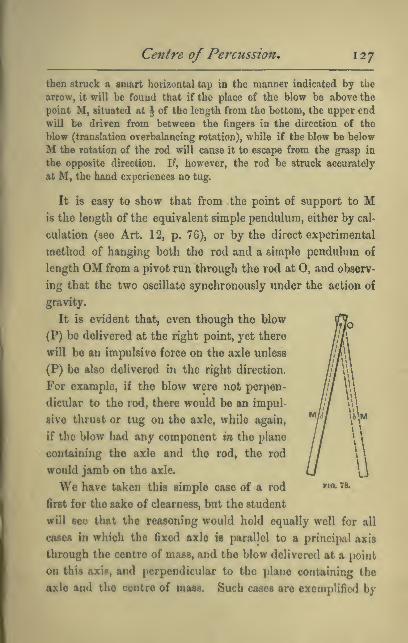
Centre of Percussion, 127
then struck a smart horizontal tap in the manner indicated by the
arrow, it will be found that if the place of the blow be above the
point M, situated at \ of the length from the bottom, the upper end
wiU be driven from between the fingers in the direction of the
blow (translation overbalancing rotation), while if the blow be below
M the rotation of the rod will cause it to escape from the grasp in
the opposite direction. If, however, the rod be struck accurately
at M, the hand experiences no tug.
It is easy to show that from the point of support to Mis the length of the equivalent simple pendulum, either by cal-
culation (see Art. 12, p. 76), or by the direct experimental
method of hanging both the rod and a simple pendulum of
length OM from a pivot run through the rod at 0, and observ-
ing that the two oscillate synchronously under the action of
gravity.
It is evident that, even though the blow
(P) be delivered at the right point, yet there
will be an impulsive force on the axle unless
(P) be also delivered in the right direction.
For example, if the blow were not perpen-
dicular to the rod, there would be an impul-
sive thrust or tug on the axle, while again,
if the blow had any component in the plane
containing the axle and the rod, the rod
would jamb on the axle.
We have taken this simple case of a rod
first for the sake of clearness, but the student
will see that the reasoning would hold equally well for all
cases in which the fixed axle is parallel to a principal axis
through the centre of mass, and the blow delivered at a point
on this axis, and perpendicular to the piano containing the
axle and the centre of mass. Such cases are exemplified by
ria 7a

128 Dyna7nics of Rotation.
(i.) A cricket bat held in the hand as by a
pivot, and struck by the ball somewhere in the
central plane of symmetry, and perpendicular to
the face.
(ii.) A thin vertical door struck somewhere
along the horizontal line through its centre of
mass, as is the case when it swings back against
a ' stop ' on the wall when flung widely open.
We see that the right position for the stop is
at a distance of \ of the breadth of the door
Fia. 79.
from the outer edge. (See Fig. 80.)
It is evident that the blow must be so
delivered that the axis through the centre of mass about
which the body, if free, would begin to turn, is parallel
to the given fixed axle, otherwise
the axle will experience an im-
pulsive twist, such as is felt by a
batsman or a racquet-player when
the ball strikes his bat to one
side of the central plane of
symmetry.
For this reason, too, a door
that is brought up as it swings
by a stop screwed to the floor^
experiences a damaging twist at
its hinges even though the
stop be placed at the right
distance from the line of hinges.
Centre of Percussion in a Body of any Form.—We have seen (p. 106) that a free rigid body, acted on by a

Centre of Percussion, 129
couple, will begin to rotate about an axis through its centre of
mass, but not in general perpendicular to the plane of the
couple, and it is evident that when a body can only turn about
a fixed axle, and is struck by an impulsive couple, the axle
will experience an impulsive twist of the kind described
unless it is parallel to this axis of spontaneous rotation.
Hence it is not possible in all cases of a body turning about a
fixed axle to find a centre of percussion, and the criterion or
test of the possibility is the following :—Through the centre
of mass draw a line parallel to the fixed axle. Rotation
about this line would, in general, involve a resultant centri-
fugal couple. If the plane of this couple contains the fixed
axle, then a centre of percussion can be foimd, not otherwise.
The significance of this criterion will be apparent after
reading the next chapter. It is easy, by imagining the body
to be replaced by its inertia-skeleton of three rectangular rods,
to see that if the fixed axle is parallel to one of the three
rods, i.e. to one of the principal axes, there is always an easily
found centre of percussion for a rightly dii-ected blow.
N.B.—It should be observed tliat when once rotation has
begun there will be a centrifugal pull on the axle, even
though the blow has been rightly directed ; but this force will
be of finite value depending on the angular velocity imparted,
and will not be an impulsive force. Our investigation is only
concerned with impulsive pressures on the axle.

CHAPTER XII.
ESTIMATION OF THE TOTAL ANGULAR MOMENTUM.
It may not be at once apparent that rotation about a given
fixed axle may involve angular momentum about an axis
perpendicular thereto.
To explain this let us take, in the first instance, two simple
illustrations.
Referring to Fig. 75, p. 124, let the rod AB be rotating
without friction about the perpendicular axle CO', while at
the same time the forked framework which carries CC is
stationary but free to turn about 00', and that when the rod
is, for example, in the position indicated, its rotation about
CC is suddenly stopped.
It is clear that in this case the sudden stoppage cannot
affect the angular velocity of the other parts of the system
about 00', for it can be brought about by the simple tighten-
ing of a string between some point on the fixed axle 00' and
some point such as A or B on the rod, or by impact with
a smooth ring that can be slipped down over the axle 00'
as indicated in Fig. 81, i.e. by forces having no moment
about 00'.
In order to test whether, in any case, the sudden stoppage
130

Simultaneous Rotations, 131
of rotation about CC shall affect the angular velocity of other
parts of the system about 00', it is sufficient to inquire
whether, when the rotation is only about CC, the sudden
stoppage involves the action of any impulsive couple
about 00'.
In the case of the thin rod just examined the impulsive
couple required is entirely in the plane of the axis 00', being
a tug at one place, and a thrust transmitted equally through
each prong of the fork in another, and therefore has no
moment about 00'.
rio. 81.
But if we suppose the simple bar to be exchanged for one
with projecting arms EF and GH, each parallel to CC and
loaded, let us say, at the ends as indicated in the figure, then,
on the sudden stoppage of the rod by the ring as before, the
momentum of the loads at F and II will tend to produce rota-
tion about AB, and therefore pressures at C and C which will
change the angular velocity of CC about 00'. It is evident,
in fact, that though we allow ourselves to speak of the
loaded rod as simply rotating about CC, yet that each of the

1 3 2 Dynamics of Rotation.
loads at F and H have angular momentum about 00', and
that when we suddenly stop the rotation about CC, we also
suddenly destroy this angular momentum about 00', which
requires the action of an impulsive couple about 00'. In
the illustration in question this couple is supplied by other
parts of the system, the reaction on which causes them to
take up the angular momentum about 00' that is lost by
the masses at F and H.
The reader will see that in the first case the amount of
angular momentum existing at any instant about 00' is not
affected by the simultaneous rotation about CC, while in the
second case it is. He will also notice that CO' is a principal
axis in the first case, but not in the second
Additional Property of Principal Axes.—Now it is
easy to show by analysis that, for a rigid body of any shape,
notation about any given axis will in general involve angular
momentum about any axis at right angles thereto, but not when one
of the two is a principal axis.
Let P (Fig. 23a, p. 56) be any particle of mass m, of a body
which is rotating, say, in a -\-ve direction, about the axis Oy,
with angular velocity Wy. The velocity of P is perpendicular
to BP, and equal to roiy ; the component to this perpendicular
to the plane a;y, which alone has any moment about Ox,=zxoiy,
and its moment about Ox= —(HyXy (negative because the rota-
tion would be counter-clockwise as viewed from 0), and
therefore the moment of momentum of the particle about
Ox=—(omxyy and summing for the whole body, the re-
sultant angular momentum about Ox=—(Oy1mxy, which

Simultaneous Rotations, 133
vanishes when either Ox or Oy is a principal axis of the
body.i
Total Angular Momentum.—It will now be clear
that even when a body rotates in rigid attachment to an axis
fixed in space, unless this axis is a principal axis the angular
momentum about it will not be the whole angular momentum,
for there will be some residual angular momentum about a
perpendicular axis which we must compound with the other
by the parallelogram law to obtain the whole angular
momentum. This completes the explanation of the fact
already noticed on p. 107, that a body free to turn in any
manner will not, when acted on by an applied couple, always
begin to rotate about the axis of that couple. The axis of
rotation will be such as to make the axis of total angular
momentum agree with that of the couple.
The Centripetal Couple.—When we put together the
result of the analysis just given with that of p. 120, we see
that we have shown that
(i) — (Uy227na:y measures the moment of the centripetal
couple about z^ and
(ii) —(Dy^mxy measures the contribution of angular
momentum about x due to the rotation about y.
Whence we see that
The moment of the centripetal couple about 2;=WyXthe con-
tribution of angular momentum about x. The significance of
this result will be best appreciated after reading Chapter xiii.
* If the rotation about CC' (Fig. 81) had been suddeuly arrested whenthe loaded rod was perpendicular to 00\ each load would then have
been at the instant moving parallel to 00', and there would have been
no moment of momentum about 00'. 00' would at this instant have
parallel to a principal axis of the body.
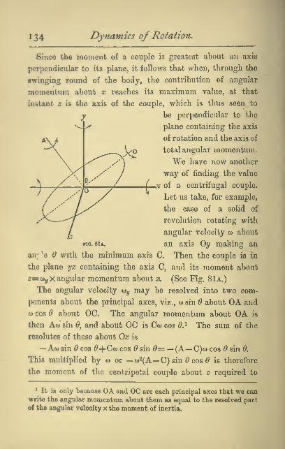
134 Dynamics of Rotation.
Since the moment of a couple is greatest about an axis
perpendicular to its plane, it follows that when, through the
swinging round of the body, the contribution of angular
momentum about x reaches its maximum value, at that
instant z is the axis of the couple, which is thus seen to
be perpendicular to the
plane containing the axis
of rotation and the axis of
total angular momentum.
We have now another
way of finding the value
a; of a centrifugal couple.
Let us take, for example,
the case of a solid of
revolution rotating with
angular velocity w about
Fio. 81a. an axis Oy making an
an; ^e 6 with the minimum axis C. Then the couple is in
the plane yx containing the axis C, and its moment about
2=a)yX angular momentum about x. (See Fig. 8lA.)
The angular velocity tuy may be resolved into two com-
ponents about the principal axes, viz., w sin 6 about OA and
CO cos d about OC. The angular momentum about OA is
then Awsin ^, and about OC is Cwcos 6.^ The sum of the
resolutes of these about Ox is
—Awsin 0COS ^-t-Ctucos ^sin ^= — (A— C)wcos ddnS.
This multiplied by w or — (o2(A— C) sin ^ cos ^ is therefore
the moment of the centripetal coujile about z required to
* It is only because OA and OC are each principal axes that we canwrite the angular momentum about them as equal to the resolved part
of the angular velocity x the moment of inertia.

Simultaneous Rotations, 135
maintain the rotation. This result with the sign changed
is the value of the centrifugal couple, and agrees with that
obtained in a different way on p. 1 22.
Rotation under the influence of no torque.—
A
rigid body of which one point, say its centre of mass, is
fixed can only move by turning about that point, and at any
instant it must be turning about some line, which we call
the instantaneous axis, passing through that point. Every
particle on that line is for the instant stationary, though,
in general, it will be gaining velocity (suctf particles will in
fact have acceleration but not velocity). Hence after a short
interval of time these same particles will no longer be at rest,
and will no longer lie on the instantaneous axis. If, however,
the axis of rotation is a principal axis, and no external forces
are acting, there will be no tendency to move away from it,
for there will be no centrifugal couple. We thus realise that
if such a body bo set rotating and then left to itself its future
motion "\vill depend on the direction and magnitude of the
centrifugal couple. After it is once abandoned, however, the
axis of total angular momentum must remain fixed in space
;
it is therefore often termed the invariable axis.

CHAPTER XIII.
ON SOME OF THE PHENOMENA PRESENTED BY
SPINNING BODIES.
The behaviour of a spinning top, when we attempt in any
way to interfere with it, is a matter that at once engages and
even fascinates the attention. Between
the top spinning and the top not spin-
ning there seems the difference almost
between living matter and dead. While
spinning, it appears to set all our pre-
conceived views at defiance. It stands
on its point in apparent contempt of
the conditions of statical stability, and
when we endeavour to turn it over,
seems not only to resist but to evade us.
The phenomena presented are best
studied in the Gyroscope, which may
be described as a metal disc AB (see
Fig. 82) with a heavy rim, capable of
rotating with little friction about an
axle CD, held, as shown in the figure,
by a frame, so that the wheel can turn
either about the axle CD, or (together with the frame CD)
about the axle EF, perpendicular to CD, or about the axl©
186
no. 82.

Phenomena presented by Spinning Bodies. 1 2il
GH, perpendicular to every possible position of EF, or the
wheel may possess each of these three kinds of rotation
simultaneously.
The axle CD we shall refer to as the axle of spin, or axle (1),
the axle EF we shall call axle (2), and the axle GH, which in
the ordinary use of the instrument is vertical, we shall call
axle (3). Suppose now the apparatus to be placed as shown in
the figure, with both the axle of spin and axle (2) horizontal,
and let rapid rotation be given to it about the axle of
spin CD.
Ezpeximent 1.—If, now, keeping GH vertical, we move the whole
bodily, say by carrying it round the room, we observe that the axle
of rotation preserves its direction unaltered as we go. Tliis is only
an illustration of the conservation of angular momentum. To change
the direction of the axle of spin would be to alter the amount of
rotation about an axis in a given direction, and would require the
action of an external couple, such as, in the absence of all friction, is
not present.
Experiment 2.—If, while the wheel is still spinning, we lift the
frame-work CD out of its bearings at E and F, we find we can move
it in any direction by a motion of translation, without observing any-
thing to distinguish its behaviour from that of an ordinary non-rotat-
ing rigid body : but the moment we endeiivour in any sudden manner
to change the direction of the axle of spin an unexpected resistance
Lb experienced, accompanied by a curious wriggle of the wheel.
Experiment 8.—For the closer examination of this resistance and
wriggle let ns endeavour, by the gradually applied pressure of smooth
pointed rods (such as ivory penholders) downwards at D and upwardsat C, to tilt the axle of spin—axle (1)—from its initial direction,
which wo will again suppose horizontal, so as to produce rotation
about EF—axle (2). We find that the couple thus applied is resisted,
but that the whole framework turns about the vertical axle GH—axle (3)—and continues so to turn as long as the pressures are applied,
ceasing to turn when the couple is removed : the direction of the

'38 Dynamics of Rotation,
rotatioD about axle (3) is counter-clockwise as viewed from above when
the spin has the direction indicated by the arrows. (See Fig. 83.)
Experiment 4.—If, on the other hand, we endeavour by means of a
gradually applied horizontal couple to impart to the already spinning
wheel a rotation about axle (3), we find that instead of such rotation
taking place, the wheel and its frame begin to rotate about the axle
(2), and continue so to rotate so long as the couple is steadily applied.
The direction of this rotation is that given in Fig. 84 below, and
Fia. 84,
the effects here mentioned may be summarised by saying that with
the disc rotating about axle (1) the attempt to impart rotation about
a perpendicular axle is resisted, but causes rotation about a third axle
perpendicular to both.
In each diagram the applied couple is indicated by straight arrows,
the original direction of spin by unbroken curved arrows, and the
direction of the rotation produced by the couple by broken curved
arrows.
It should be noticed that it is only for convenience of
reference that we suppose the axis of spin to be initially hori-
zontal. Had this axis been tilted, and axle (3) placed per-
pendicular to it, the relation of the directions would be the
same.
Definition.—The rotation of the axle of spin in a plane per-
pendicular to that of the couple applied to it is called a pre-

Phenomeyia presented by Spinning Bodies, 139
cessional motion—a phrase borrowed from Astronomy—and
we shall speak of it by that name. The application of the
couple is said to cause the spinning wheel to ' precess.'
Rule for the direction of Precession.—In all cases
the following Rule, for which the reason will be apparent
shortly, will be found to hold.
The Precession of the axle of spin tends to convert the existing
spin into a spin about the axis of the couple and in the direction
required by the couple.
Experiment 6.—The actions just described may be well exhibited
by attaching a weight at or D, as in the accompanying figure
no. 85. no. 9k
(Fig. 85), or still more strikingly, by supporting the frame CD on n
point P, by means of a projection DK, in whose lower side is a
shallow conical hollow, in the manner indicated in the figure (Fig. 8C).

140 Dynamics of Rotation,
If the wheel were not spinning it would at once fall, but instead of
falling it begins when released to travel with processional motion round
the vertical axis HP, and even the addition of a weight W to the
framework at C will, if the rate of spin be sufficiently rapid, produce
no obvious depression of the centre of gravity of the whole, but only
an acceleration of the rate of precession round HP. It will, indeed,
be observed that the centre of gravity of the whole does in time
descend, though very gradually, also that the precession grows more
and more rapid.
Each of these eflfects, however, is secondary, and due, in
part at any rate, to friction, of which we can never get rid
entirely.
In confirmation of this statement we may at once make the
two following experiments.
Experiment 6.—Let the precession be retarded by a light hori-
zontal couple applied at and D. The centre of gravity at once
descends rapidly. Let the precession be accelerated by a horizontal
couple. The centre of gravity of the whole begins to rise. Thus
we see that any friction of the axle GH in Fig. 85, or friction
at the point P in Fig. 86, will cause the centre of gravity to
descend.
Experiment 7.—Let Experiment 6 be repeated with a much smaller
rate of original spin. The value of the steady precessional velocity
will be much greater. Hence we see that friction of the axle of spin
might account for the gradual acceleration of the precessional velocity
that we observe.
Experiment 8.—Let us now vary the experiment by preventing
the instrument from turning about the vertical axle (3), which
may be done by tightening the screw G (Fig. 82), the base of the
instrument being prevented from turning by its friction with the
table on which it stands. If we now endeavour as before to tilt
the rotating wheel, we find that the resistance previously experienced
has disappeared, and that the wheel behaves to all appearance as if
not spinning.

P/ienofnena presented by Spinning Bodies. 1 4
1
Experiment 9.—But if the stem GH be held in one hand, while with
the other a pressure is applied at C or D to tilt the wheel, its 'effort
to precess * will be strongly felt.
Experiment 10.—Let us now loosen the screw G again, but fix the
frames CD, which may be done by pinning it to the frame EF, so as
to prevent rotiition about the axle EF. It will now be found that
if, as in Experiment 4, we apply a horizontal couple, the previously
felt resistance has disappeared ; but here, again, the * effort to precess
'
will be strongly felt if the framework CD be dismounted and held in
the hand, and then given a sudden horizontal twist.
Precession in Hoops, Tops, etc.—It needs only the
familiarity that most of us obtain as children with hoops,
tops, bicycles, etc., to recognise that we have in these also the
very same phenomenon of precession to explain. Thus, when
a hoop rolling away from us
is tilted over to the left, it
nevertheless does not fall as
it would if not rolling. Since
the centre of gravity does not
descend, the upthrust at the
ground must be equal to the
weight of the hoop, and must
constitute with it a couple
tending to turn the hoop over.
Wo observe, however, that
instead of turning over, the hoop turns to the left, i.t. it
takes on a processional motion.
If we forcibly attempt with the hoop-stick to make it turn
more quickly to the left, the hoop at once rears itself upright
again (compare Experiment 6).
It is true that when the hoop u bowling along a curved
path of radius R in an inclined position, as shown in the
)tv\. S7

142 Dynamics of Rotation,
figure, there is a couple acting on it in a vertical plane, due to
the centrifugal force ^~ , and the lateral friction of the
ground. But this will not account for the curvature of the
track, nor can it be the sole cause of the hoop not falling over,
for if the hoop be thrown from the observer in an inclined
position, and spinning so as afterwards to roll back towards
him, it will be observed not to fall over even while almost
stationary, during the process of 'skidding,' which precedes
the rolling back.
Further Experiment with a Hoop.—It is an instruc-
tive experiment to set a small light hoop spinning in a ver-
tical plane, in the air, and then, while it is still in the air, to
strike it a blow with the finger at the extremity of a horizon-
tal diameter. The hoop will at once twn over about that
diameter. If the experiment be repeated with the hoop not
spinning, the hoop will not turn over, but will rotate about a
vertical diameter. This experiment will confirm the belief in
the validity of the explanation above given of the observed
facts.
That a spinning top does not fall when its axis of spin is
tilted is evidently an instance of the same kind, and we shall
show^ (p. 154) that the behaviour of a top in raising itself from
an inclined to an upright position is due to an acceleration of
the precession caused by the action of the ground against its
peg, and falls under the same category as the recovery of posi-
tion by the hoop, illustrated in experiments 4 and 6 with the
gyroscope.
* Sec also p. 70 of a Lecture on Spinning Tops, by Professor JohnPerry, F. R. S. Published by the Society for Promoting Christian Know.ledge, Charing Cross, London, W.C.
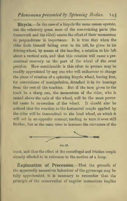
Phenomena presented by Spinning Bodies, 143
Bicycle.—In the case of a bicycle the same causes operate,
but the relatively great mass of the non-rotating parts (the
framework and the rider) causes the efiect of their momentum
to preponderate in importance. It is true that when the
rider finds himself falling over to his left, he gives to his
driving-wheel, by means of the handles, a rotation to his left
about a vertical axis, and that this rotation will cause a pro-
cessional recovery on the part of the wheel of the erect
position. How considerable is this eflbrt to precess may be
readily appreciated by any one who will endeavour to change
the plane of rotation of a spinning bicycle wheel, having first,
for convenience of manipulation, detached it in its bearings
from the rest of the machine. But if the turn given to the
track be a sharp one, the momentum of the rider, who is
seated above the axle of the wheel, will be the more power-
ful cause in re-erection of the wheel. It should also be
noticed that the reaction to the horizontal couple applied by
the rider will be transmitted to the hind wheel, on which it
will act in an opposite manner, tending to turn it over still
further, but at the same time to increase the curvature of the
no. 88.
track, and thus the effect of the centrifugal and friction couple
already alluded to in reference to the motion of a hoop.
Explanation of Precession.—That the grounds of
tlic apparently anomalous behaviour of the gyroscope may be
fully apprehended, it ia necessary to remember that the
principle of the conservation of angular momentum implies

144 Dynamics of Rotation.
(i) That the application of any external couple involves tne
generation of angular momentum at a definite rate about the
axis of the couple ; and (ii) That no angular momentum about
any axis in space can be destroyed or generated in a body
without the action of a corresponding external couple about
that axis. Now, if the spinning wheel were to turn over
under the action of a tilting couple as it would if not spinning,
and as, without experience, we might have expected it to do,
the latter of these conditions would be violated. For, as the
wheel, whose axis of spin was, let us suppose, originally hori-
zontal, turned over, angular momentum would begin to be
generated ^ about a vertical axis without there being any
corresponding couple to account for it; and if the tilting
continued, angular momentum would also gradually disappear
about the original direction of the axle of spin, and again
without a corresponding couple to account for it.
On the other hand, by the wheel not turning over in
obedience to the tilting couple, this violation of condition (ii)
is avoided, and by its precessing at a suitable rate condition
(i) is also fulfilled. For, as the wheel turns about the axis
of precession, so fast does angular momentum begin to appear
about the axis of the couple as required.
* When the wheel is simply spinning about axis (1) the amount of
angular momentum about any axis in space drawn through its centre, is
(see p. 89) proportional to the projection in that direction of the length
of the axle of spin. Or again, the amount of angular momentumabout any axis is proportional to the projection of the circular area
of the disc which is visible to a person looking from a distance at
its centre along the axis in question. Thus, if the axis were to
begin to be tilted up, a person looking vertically down on the wheelwould begin to see some of the flat side of the wheel. The student
will find this a convenient method of following with the eye andestimating the development of angular momentum about any axis.

Phenomena presented by Spinning Bodies, 145
Analogy between steady Precession and uniform
Motion in a Circle.—To maintain the uniform motion of
a particle along a circular arc requires, as we saw on p. Ill,
the application of a force, which, acting always perpendicular
to the existing momentum, alters the direction but not the
magnitude of that momentum. Similarly, for the mainten-
ance of a steady precession, we must have a couple always
generating angular momentum in a direction perpendicular
to that of the existing angular momentum, and thereby alter-
ing the direction but not the magnitude of that angular
momentum.
We showed (pp. Ill, 112) that to maintain rotation with
angular velocity <«> in a particle whose momentum was mv,
required a central force of magnitude wiiw, and we shall now
find in precisely the same way, using the same figure, the
value of the couple (L) required to maintain a given rate of
precession about a vertical axis in a gyroscope with its axle
of spin horizontal.
Calculation of the Rate of Precession.—Let w be
the rate of precession of the axle of spin. Let I be the
moment of inertia of the wheel about the axle of spin.
Let 12 be the angular velocity of spin.
Then Ift is the angular momentum of the wheel about an
axis coinciding at any instant with the axle of spin.*
It is to be observed, that in the absence of friction at the
pivots, the rate of spin about the axle of spin remains
unaltered.
* The student is reminded that, on account of the already existing
preceHion, the angular momentum about the axle of spin would not
be in if this axle wore not also a principal axis, and at right-angles
to the axis of precession («e« p. 132).
K

146 Dynamics of Rotation,
Let us agree to represent the angular momentum 112 about
the axle of spin when in tlie position OA by the length OPmeasured along OA. Then the angular momentum about
the axle when in the position OB is represented by an equal
length OQ measured along OB, and the angular momentum
added in the interval is re-
presented by the line PQ.
If the interval of time con-
sidered be very short, then
OB is very near OA, and PQis perpendicular to the axle
OA. This shows that the
angular momentum added,°;
Fia. 80.
and therefore the external
couple required to maintain the precession, is perpendicular
to the axle of spin.
Let the very short interval of time in question be called
{dt)^ then PQ represents the angular momentum added in time
((//), i.e. (the external couple) x {di).
, PQ_ external couple x idt)
" op~ m •
But ^=angle 1^0q=io{dt)
;
, external couple X (dt) _ , ,,...
j^^(o(rfj;,
or external couple =Ifia).
The analogy between this result and that obtained for the
maintenance of uniform angular velocity of a particle in a
circle becomes perhaps most apparent when written in the
following form :
—
*To rotate the linear momentum m'o with angular velocity

Phenomena presented by Spinning Bodies. 147i .
0) requires a force perpendicular to the momentum of magni-
tude mv.io.
'While
* To rotate the angular momentum 112 with angular velocity w
requires a couple, about an axis perpendicular to the axis of
the angular momentum, of magnitude Iflw.'
Since then L= I12tu
L"=T12»
or the rate of precession is directly proportional to the mag-
nitude of the applied couple, and inversely as the existing
angular momentum of spin.
That the rate of precession (o>) increases as the rate of
spin 12 diminishes has already been shown (see Experiments
5 and 7).
But the result obtained also leads to the conclusion that,
when the rate of spin is indefinitely small, then the rate of
precession is indefinitely great, which seems quite.contrary to
experience, and requires further examination.
To make this point clear, attention is called to the fact
that our investigation, which has just led to the result that
o»=^--, applies only to the maintenance of an existing precession^
and not to the starting of that precession from rest. Assum-
ing no loss of spin by friction, it is evident that there is more
kinetic energy in the apparatus when precessing especially
with its frame, than when spinning with axle of spin at rest.
In fact, if t be the moment of inertia of the whole apparatus
about the axle, perpendicular to that of spin, round which
precession takes place, the kinetic energy is increased by the
amount }t(u', and this increase can only have been derived
from work done by the applied couple at starting. Hence,

148 Dynamics of Rotation,
in starting the precession, the wheel must yield somewhat to
the tilting couple.
Observation of the * Wabble.'—This yielding may be
easily observed if, when the wheel is spinning, comparatively
slowly, about axis (1), we apply and then remove a cOuple
about axis (2) in an impulsive manner, for example. by a
sharp tap given to the frame at C. The whole instrument
will bo observed to wriggle or wabble, and if close attention
be paid, it will be noticed that the axle of spin dips (at one
end), is quickly brought to rest, and then begins to return,
swings beyond the original (horizontal) position, comes quickly
to rest, and then returns again, thus oscillating about a mean
position. Meanwhile, and concomitantly with these motions,
the framework CD begins to precess round a vertical axis,
comes to rest, and then swings back again. The two motions
together constitute a rotation of either extremity of the axle
of spin. If the rate of spin be very rapid, these motions will
be found to be not only smaller in amplitude, but so fast as
not to be easily followed by the eye, which may discern only
a slight * shiver ' of the axle. Or, again, a similar effect may
be observed to follow a sudden tap given when the whole is
precessing steadily under the pressure of an attached extra
weight.
It will probably at once, and rightly, occur to the reader
that the phenomenon is due to the inertia of the wheel and
its attached frame, etc., with respect to rotation about the
axis of precession. To any particular value of a tilting couple,
and for a given angular momentum of spin about axis (1),
there must be, as we have seen, so long as the couple is
applied, an appropriate corresponding value for the pieces-
Pkenonte?ta presented by Spinning Bodies. 149
sional velocity, but this velocity cannot be at once acquired
or altered. The inertia of the particles remote from the axis
of precession enables them to exert forces resisting preces-
sion, and we have seen as an experimental result (Experi-
ments 6 and 8), that when precession is resisted the wheel
obeys the tilting couple and turns over, acquiring angular
velocity about the axis of the couple. But the parts that
resist precessional rotation must, in accordance with the
principle that action and reaction are equal and opposite,
themselves acquire precessional rotation. Hence, when the
impulsive couple, having reached its maximum value, begins
to diminish again, this same inertia has the effect of hurrying
the precession, and we have also seen in Experiment 6, that
to hurry the precession is to produce a (precessional) tilt
opposite to the couple inducing the precession, and this action
destroys again the angular velocity about the axis of the
applied couple which has just been acquired. The wabble
onco initiated can only disappear under the influence of
frictional forces.* Thus the wabbling motion is seen to be
* We can now see in a general way in what manner our equation
must be modified if it is to represent the connection between the
applied couple and the rate of precession during the wabble. Theyielding under the applied couple implies that this is generating
angular momentum about its ovm axis by the ordinary process of
generating angular acceleration of the whole object about that axis,
and thus less is left unbalanced to work the alternative process of
rotating the angular momentum of spin. In fact, if our equation is to
hold, we must write (in an obvious notation)
L-Isca2=wx angular momentum about horizontal axis perpendicular
to the axis of the couple.
But the motion being now much more complicated than before, the
angular momentum al>out the horizontal axis that is being rotated
can no longer be so simply oxpresaed. Ab wo hftve seen, it is not inde>
pendent of w^

150 Dynamics ofRotation,
the result of forces tending first to check and then to
accelerate precession, a phenomenon that has been already
observed. But to observe one phenomenon, and then to
point put that another is of the same kind, cannot explain
both, and it is still desirable to obtain further insight into
the physical reactions between the parts, which enables a
couple about axle 2 to %taxt precession about axle 3, and vice
versd.
Explanation of the Starting of Precession.—
Suppose that we look along the horizontal axis of spin at
the broad-side of the disc spinning as indicated by the arrow
(Fig. 90), and that there is applied to it a couple about axle
(2) tending, say, to make the upper half of the disc advance
towards us out of the plane of the diagram, and the lower
half to recede. We shall show that simultaneously with the
rotation that such a couple produces about axle (2), forces are
called into play which start precession about (3).
All particles in quadrant (1) are increasing their distance
from the axis (2), and therefore (see pp. 85 and 86) checking
the rotation about (2), producing, in fact (on the massless
rigid structure within the cells of which we may imagine
them lying as loose cores), by reason of their inertia, the
effect of a force away from the observer applied at some
point A in the quadrant. Similarly, all particles in quad-
rant (2) are approaching the axis (2), and therefore by their
momentum perpendicular to the plane of the diagram arc
accelerating the rotation about (2), producing on the rigid
structure of the wheel the effect of a pressure towards the
observer at some point B. In like manner, in quadrant (3),
in wliicb the particles are receding from axis (2), they exert

Pheyiomena presented by Spinning Bodies. 1 5
1
on the rigid structure a resultant force tending to check the
rotation about (2),
equal and opposite to |(3)
that exerted at A,
and passing through
a point C similarly
situated to A. Again,
in quadrant (4) the
force is away from the
observer, is equal to
that at B, and passes
through the similarly
situated point D.
These four forces con-
stitute a couple which
does not affect the rotation about (2), but does generate pre-
cession about (3).
On the other hand, when precession is actually taking place
about axis (3), we see, by dealing in precisely the same way
with the several quadrants, and considering the approach or
recession of their particles to or from axis (3), that the spin
produces a couple about axis (2) which is opposed to and
equilibrates the external couple that is already acting about
axis (2), but which does not affect the rotation about axis (3).
If, when precession about (3) is proceeding steadily, the
external couple about (2) be suddenly withdrawn, then this
opposing couple is no longer balanced, and the momentum
of the particles initiates a wabble by causing rotation
about (2).i
^ Some roaden ouy find it easier to follow this explanation by

152 Dynamics of Rotation,
Gyroscope with Axle of Spin Inclined.—It will be
observed that we have limited our study of the motion of the
spinning gyroscope under
the action of a tilting
couple to the simplest
case of all, viz., that in
which the axle of spin is
perpendicular to the ver-
tical axle, which there-
fore coincides with the
axis of precession. If we
had experimented with
the axle of spin inclined
as in Fig. 91, then the
axis of precession, which,
as we have seen, must
always be perpendicular
to the axis of spin, would
have been itself inclined,
and pure rotation about it would have been impossible owing
to the manner in which the frame CD is attached to the
vertical axle. The former precessional rotation could be
resolved into two components, one about the vertical axis
which can still take place, and one about a horizontal axis
which is prevented.
Now, we have seen that the effect of impeding the preces-
sional rotation is to cause the instrument to yield to the
FIO. 91.
imagining the disc as a hollow massless shell or case, inside which each
nuasive particle whirls round the axis at the end of a fine string, andto think of the way in wliich the particles would strike the flat sides
of the case if this were given the sudden turn about axle 2.
Phenomena presented by Spinning Bodies. 153
tilting couple. Hence we may expect to find that the sudden
hanging on of a weight, as in the figure, will cause a more
marked wabble of the axle of spin than would be produced
by an equal torque suddenly applied when the axle of spin
was horizontal. This may be abundantly verified by experi-
ment. It will be found that if the instrument be turned
from the position of Fig. 91 to that of Fig. 85, and the same
tap be given in each case, the yield is far less noticeable in
the horizontal position, although (since the force now acts on
a longer arm) the moment of the tap is greater ; and if other
tests be applied, it will be observed that the quasi-rigidity of
the instrument, even when spinning fast, is notably dimin-
ished when the axle of spin is nearly vertical, i.e. when
nearly the whole of the precession is impeded.
Pivot-friction is liable to be greater with the axle of spin
inclined, and this producos a more noticeable reduction of
the rate of spin, with a corresponding increase of tilt and
acceleration of the precession, which (as we show in the
Appendix) would otherwise have a definite steady value.
The precession also is now evidently a rotation about an axis
which is not a principal axis of the disc, and on this account
a centrifugal couple is called into play, tending, in the case
of an oblate body like the gyroscope disc, to render the axle
more vertical, i.e. to help the applied couple, if the weight
is hung at the lower end of the axle, as in the figure, but
to diminish the couple if the weight is hung from the
upper end.
It most be remembered, however, that the disc of a g3T0-
scope can only process in company with its frame, CD, and the
dimensions and mass of this can be so adjusted that the disc
and frame together are dynamically equivalent to a sphere.

154 Dynamics of Rotation,
every axis being then a principal axis as regards a common
rotation of disc and frame. In this manner disturbance
by the centrifugal couple may be
avoided.
In dealing with a peg-top moving
in an inclined position with preces-
sional gyration about a vertical axis
(see Fig. 93), such centrifugal forces
will obviously need taking into ac-
count. With a prolate top, such as
that figured, the efifect of the centri-
fugal couple will be to increase the
applied couple and therefore the rate
of precession; with a flattened or
oblate top like a teetotum, to
diminish it.
The exact evaluation of the steady
precessional velocity of gyroscope or
top with the axis of spin inclined,
will be found in the Appendix.nos. 02 AND
Explanation of the Effects of Impeding or Hurry-ing Precession.—Though we have throughout referred
to these effects as purely experimental phenomena, the ex-
planation is very simple. The turning over of the gyroscope,
when the steady precession is impeded, is itself simply a
precessional motion induced by the impeding torque. Refer-
ence to the rule for the direction of precession (p. 139) will
show that the effect either of impeding or hurrying is at once
accounted for in this way.
The Rising of a Spinning Top.—We have already

Phenomena presented by Spinning Bodies, 155
(p. 142) seen that this phenomenon would follow from the
action of a torque hurrying the precession, and have intimated
that it is by the friction of the peg with the ground or table
on which the top spins that the requisite torque is provided.
We shall now explain how this frictional force comes into play.
The top is supposed to be already spinning and process-
ing with its axis in-
clined as indicated in /Fig. 93. The relation / 1
between the directions / \^of tilt, spin, and pre- / ^-->- y/1 ••
cession is obtained by / >^
the rule of page 139, ^i >^-..__
and is shown by the~''~
^^:^=̂"^
7^arrows of Fig. 94, repre- \senting the peg of the ^%y/top somewhat enlarged. ""^:^^
The extremity of the
peg is always somewhat rounded, and the blunter it is, the
farther from the axis of spin will be the part that at any in-
stant is in contact with the table. On account of the proces-
sional motion by which the peg is swept bodily round the
horizontal circle on the table, this portion of the peg in contact
with the table is moving forwards, while, on the other hand, on
account of the spin, the same part is being carried backwards
over the table. So long as there is relative motion of the
parts in contact, the direction of the friction exerted by the
table on the peg will depend on which of these two opposed
velocities is the greater. If the forward, precessional velocity
is the greater, then the friction will oppose precession and
increase the tilt ; while if the backward linear velocity due

1 56 Dynamics of Rotation,
to the spin is the greater, then the peg will skid as it sweeps
round and the friction will be an external force aiding pre-
cession, and the top will rise to a more vertical position.
When the two opposed velocities are exactly equal, then the
motion of the peg is one of pure rolling round the horizontal
circle: there is then no relative motion of the parts in con-
tact, parallel to the table, and the friction may be in either
direction, and may be zero.
With a very sharp peg, of which the part in contact with
the table is very near the axis of spin, the backward linear
velocity will be very small, even with a rapid rate of spin
;
80 that such a top will less readily recover its erect position
than one with a blunter peg. Also on a very smooth surface
the recovery is necessarily slower than on a rough one, as
may easily be seen by causing a top which is spinning and
gyrating and slowly erecting itself on a smooth tray, to move
on to an artificially roughened part.
The explanation here given, though somewhat more de-
tailed, is essentially the same as that of Professor Perry in
his charming little book on Spinning Tops already referred to,
and is attributed by him to Sir William Thomson.
We will conclude by recommending the student to spin, on
surfaces of different roughness, such bodies as an egg (hard-
boiled), a sphere eccentrically loaded within, and to observe
the circumstances under which the centre of gravity rises or
does not rise. Bearing in mind the explanation just given,
he should now be able to account to himself for what he will
observe, and to foresee what will happen under altered con-
ditions.
Calculation of the 'EfTort to Precess.'—We saw,

Phenomena presefited by Spinnmg Bodies, 157
in Experiments 9 and 10, that when precession is prevented
an * effort to precess ' is exerted by the spinning body against
that which prevents it. Thus, in the experiments referred
to, pressures equivalent to a couple were exerted by the axle
of the spinning wheel on its bearings.
If 0) be the rate at which the axle of spin is being forcibly
turned into a new direction, then wlfi is the rate at which
angular momentum is being generated about the axis per-
pendicular to the axis of w and to that of 12, and is therefore
the measure of the torque exerted by the bearings, and of the
reaction to which they are themselves in turn subjected.
Example (l).—A railway-engine whose two driving-wheels have
each a diameter d( = 7 feet) and a moment of inertia I( = 18500 Ib.-
foot* units) rounds a curve of radius r( = 528 feet) at a speed v( = 30
miles per hour). Find the effort to precess due to the two wheels.
Solution—2v
Q = -j = 12*57 radians per second.
•» =— = £^j5 = T^T radians per second.r 52o 12
.% Moment of couple required = 2lQa) absolute units.
= 1200 pound-foot units
(very nearlyj.
Applying the rule for the direction of precession, we see that this
couple will tend to lift the engine off the inner rail of the curve.
[We have left out of consideration the inclination which, in prac-
tice, would be given to the wheels in rounding such a curve, since
this will but slightly affect the numerical result.]
Similar stresses are produced at the bearings of the rotating
parts of a ship's machinery by the rolling, pitching, and turn-
ing of the ship. In screw-ships the axis of the larger parts
of such machinery are in general parallel to the ship's keel,
and will therefore bo altered in direction by the pitciiing and
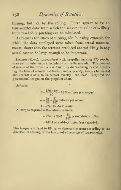
1 58 Dynamics of Rotation.
turning, but not by the rolling. There appear to be no
trustworthy data from which the maximum value of w likely
to be reached in pitching can be calculated.
As regards the effect of turning, the following example, for
which the data employed were taken from actual measure-
ments, shows that the stresses produced are not likely in- any
actual case to be large enough to be important.
Example (2).—A torpedo-boat with propeller making 270 revolu-
tions per minute, made a complete turn in 84 seconds. The momentof inertia of the propeller was found, by dismounting it and observ-
ing the time of a small oscillation, under gravity, about a horizontal
and eccentric axis, to be almost exactly 1 ton-foot^. Required the
precessional torque on the propeller shaft.
Q_ 270x27r
6028'3 radians per second.
o) = -^= -—: radians per second.84 147
1= 2240 lb.-foot2 units.
,*. torque required = iQw absolute units.
= 2240 X 28-3 x^ poundal-foot units,
= 148*4 pound-foot units (very nearly).
This torque will tend to tilt up or depress the stern according to the
direction of turning of the boat, and of rotation of the propeller.

APPENDIX
PRECESSION OF GYROSCOPE AND SPINNING TOP
WITH AXIS INCLINED.
The value (<») of the steady precessional velocity of a gyro-
scope whose axis is inclined at an angle d to the vertical,
where an external tilting couple of moment L is applied
about the axis EF (see Fig. 91) may be found as follows.
Referring still to Fig. 91, let the vertical axis of precession
be called (y) and the axis EF of the couple, (^), and the hori-
zontal axis in the same plane as the axle of spin (x). Let Cbe the moment of inertia of the disc about the axle of spin,
A its moment about a perpendicular axis, and let fi be the
angular velocity of spin relative to the already moving frame.
(1) Let the dimensions of the ring have been adjusted in
the way mentioned on p. 153 so that the rotation about y in-
troduces no centrifugal couple. Then the value of the angular
momentum about (x) is simply C12 sin ^, and to rotate this
about (y) with angular velocity (w) will require a couple (L)
about (z) equal to a>Cfi sin 9.
Whence <ii=z —Cil sm
It follows that with a gyroscope so adjusted the rate of steady
precession produced by a weight hung on as in Fig. 91 will
bo the same whether the axis be inclined or horizontal for
the length of the arm on which the weight acts, and therefore
the couple L, is itself proportional to sin 9.
N.B.—^Tho resolute of <u about the axis perpendicular to
EF and CD is^ as before (p. 147).
(2) Let the ring and disc not have the adjustment men-
tioned, and let the least and greatest moments of inertia of
160

i6o Dynamics ofRotation,
Fig,
the ring be C and A' respectively. If the disc were not
spinning in its frame, i.e. if 12 were zero, we should require
for equilibrium a centripetal couple (see p. 122) equal to
— (A^C)w' sin ^cos ^—(A'— C')a>' sin ^ cos Q, On account of
the spin an additional angular momentum Ci2 sin Q is added
about x, to rotate which requires an additional couple
o>C12 sin B. Whence the total couple required
= L=Cfia) sin ^-(A-C-A'-C')a)' sin 6* cos Q,
which gives us w.
In the case of a top precessing in the manner indicated in
95, the tilting couple is rrnjl sin ^, and the only differ-
ence in the solution is
^ that there is no frame,
so that A'= OandC'=0.But it will be observed
that our 12 still means
the velocity of spin rela-
tive to an imaginary
frame swinging round
with the top. The quad-
ratic equation for a> thus
becomes mgl = Cfiw —(A-CKcos6'.We might, if we had
preferred it, in each case
have simply found by
resolution the total angular momentum about (x) after the
manner of page 134, and, multiplying this by w, have obtained
the value of the couple about z. But by looking at the matter
in the way suggested the student will better realise the fact
that the centripetal couple is that part of the applied couple
which is required to rotate the angular momentum contri-
buted about X by the precessional rotation itself.
fff'^)
no. 95.
Printed by T. and A. Constable, Printers to Her Majesty,
at the Edinburgh University Press.

F
d^
UNIVERSITY OF TORONTO
LIBRARY
Acme Library Card Pocket
Under I'at. " Kef. Index Kile."
MAde by LIBRA&T BUEEAU

Recommended
![Efficiency of Wave-Driven Rigid Body Rotation Toroidal ... · arXiv:1611.04166v1 [physics.plasm-ph] 13 Nov 2016 Efficiency of Wave-Driven Rigid Body Rotation Toroidal Confinement](https://img.pdfslide.net/doc/110x75/5b99319309d3f26e678b6bbf/eciency-of-wave-driven-rigid-body-rotation-toroidal-arxiv161104166v1.jpg)