〈1
明治大学大学院 理工学研究科
2000年度
博十学位請求論文
Synthesis of Grafted PolydimethylsiloxaneMembranes with Fluoroalkyl Methacrylate and theirVolatile Organic Compounds Separation Properties
(フルオロアルキルメタクリレートグラフトポリジメチルシロキサン膜の合成と
それらの膜の揮発性有機化合物の透過性に関する研究)
学位請求者 三島 聡子

ABSTRACT
MISHIMA, SATOKO. Permeability of Organic Compounds in S川cone Rubber Membrane
and Fluoroalkyl Methacry且ate Grafted Silicone Rubber Membralles.(Under the directi()110f
Professor Tsutomu Nakagawa.)
Recently, it has been a s(,cial prob且em that ground water and so註are contalninated wiIh
volatile organic compounds(VOCs). Removal of VOCs from water by pervaporation has
been studjed. The membranes that allow VOCs to permeate preferentia且ly can be applied to
the removal of very iow concentrations of VOCs like chlorinated hydrocarbons from these
colltaminated water(<10009/m3). Pervaporation performance of a membralle is determilled
by both the sorption and the diffusion characteristics of the perlneating con1Ponents in the
membrane. The solubility and diffusMty are achieved by the dit’ference ill the lnetnbrane
solubility and permeability of the feed solution components. Po星ydimethytsiloxane(PDMS》
has been well-known as an excellent polymer membrane material for its high permeability to
gases and liquids. Fluorillated polymers have the hydrophobicity based on their low surface
energy and their hydrophobic nature was expected to promote the selective adsorption alld
transport of the organlc component inawater so】ution. In this study, the PDMS membralles
were improved using伽oroalkylmethacrylates(FALMA), whlch has vinyl functi()nal group
and easy radical formation, to enhance the affinity of PDMS for chlori nated hydr()carbons.
For this improvement, blending of PDMS and poly(FALMA)is difficu亘t due to the low
affinity of PDMS for poly(FALMA). There is the possibjJity of preparing graft〔)r bjock
copoiymers of them.
The PDMS membranes were grafted by FALMA using various irradiation source.
FALMA had the effect of increasing the se且ectivity for VOCs. The novel grafted PDMS
membrane had Ihe diffe rence of polymer structure by various lrradia重ion methods、 The
permeation properties of the various grafted PDMS membranes were characterized.

The basic permeation behavior for PDMS membrane was investigated. The hydration
effect oll the s()rption-diffusion mechanism for various organic compounds was investigated
ill pervaporatioll thr()ugh the PDMS membrane. Almost a且l water moiecules are concerned
with hydration when the concentration of(water molecules)/(solute molecules)isthe same as
the hydratiol111しmlber. When the actual concentration was over this concentration, the water
mdecules hydrate to several s(,lute molecules and the motion of the water mo)ecules is
prevented. During pervaporation, the solute was concelltrated in the PDMS membrane alld
the diffusion of water molecules was prevented. It is concluded that not only the volume of
penetrate but also the hydratioll considerab且y affect on the diffusivity。
The PDMS membrane in which FALMA alld alkylmethacrylates(ALMA)were sorbed.
was irradiated by UV and utilized in pervaporation. The polymerized FALMA and ALMA
were contained in a modifled membrane. The contained amounts of FALMA and ALMA
were arotmd 1 wt (7,・. The almost same values were obtained for each FALMA alld ALMA.
The sorbed TCE ill the modified membrane increased with increasing length of the
fhK)ri nated:ide chaiii of FALMA, i.e., the number of fl uori ne atoms. The membrane that
showed the best separatioll performance was the membrane having the highest TCE
cotlcentratioTl in the sorbed solution. With increasing feed concentration, water diffusivity
decreased. Due to the introduction of a hydrophobic polymer, FALMA. the TCE quantity
s呪)rbed illto the membralle was so high that the diffusion of water was prevented・in turn. the
flux decreased,
The e仔ect of sohlbiiity and diffusibility of a monomer on graft polymerization by
electroll beam according to solubility parameter、 octanol-water partition coefficient(Pow)alld
the molecular volume of the monomer was investigated. The difference in the sorpted ainoullt
く)rgrafted amolmt was liωe when considering the diffe re nce of the solubility parameter and
the IogPow. The s orpted amount and grafted amount were affected by the molecular volume.
The sorpted am(川nt fく)r ALMA that have low molecular volume was high. The sorpted
amotmt for FALMA that have high molecular volume was low, Compared to each other in
のthe same groupく}f FALMA or ALMA. the sorpted and grafted amount for the mon【)mer
li

whlch has low molecular vohlme was high、 and Ihe sorρted and grafted amount for亘1】()110mer
which has high molecular vo)ume was low. The various grafted alllo田1ts were obtained for
FALMA and ALMA in different from the modification by UV irradiation. The pervaporation
for the PDMS membrane、 PDMS membrane irradiated by electroll beam,9!・afted PDMS
membranes was illvestigated. lt is thought that the PDMS membralles were made brittle b>
electron beam irradiation, FALMA grafted PDMS membraneg. f howed excellellt sorptk)mmd
pervaporation separation performance.
The PDMS meinbrane was improved by the graft polymerization with l H,田、9H-
hexadecafluorononyl methacrylate(HDFNMA)by plasma, which had a long n-tlttoroalk>,1
chain and the effect oll increasing the se且ectivity for VOCs. The plasma technique d〈)es not
require a high installation cost for the ellergy source. The radical tbrinati(一》n is easily
pe!formed on the surface ofthe polymer. The treatment time is short、 within a few millutes.
The degree of grafting aild oxidation simultaneousiy increased with plasma p〔)wer, The tlux
of the grafted PDMS membrane illcreased with increasing piasma power。 The degree of
grafting lncreased with increasing p且asma irradiation time. The flux of the grafted PDMS
membrane was constant regardless of the plasma irradiation time, Whell the PDMS
membranes were irradiated at iOW for i80s alld grafted. the grafted membralles were llot
brittle and the permselectivity increased. Because the grafted alnount of the plasma grat”ted
PDMS membrane was little and the advantage of rubbery PDMS membralle remailled, the
relationship between the feed concentration and the permeate concentration was observed to
be linear.
The sorption and diffusion for various VOC-w飢er mixture durh】g pervaporation
through the PDMS membrane and HDFNMA grafted PDMS membrane by plasm{奄
preirradiatioll were inveg. tigated. The TCE fl ux was prevented by benzene during
pervaporation of the TCE-benzene-water mixture through the grafted PDMS
membrane.Permselectivity is determined by the sorption and the diffusion characteristics of
the permeating components in the membrane. The permse量ectMty of PCE and toluene was
high. Because the solute quickly permeates in the rubbery membrane like PDMS、
血

permselectivity was not affected by diffusivity. Solubility significantly affects the
permselectibity during pervaporation through the hydrophobic rubbery membrane.
The PDMS membrane was grafted by HDFNMA using a 60Co source. The PDMS
membrane and HDFNMA are irradiated simultaneously. The grafted amolmt by
simultaneous irl’adiation was more than by preirradiation methods, and the permeation
behavior w川be expected to be differ from the rubbery untreated PDMS membrane and the
grafted membranes by preirradiatk)n Inethod. The grafted and poEymerized HDFNMA by a
60Co simuitaneously lrradiation was swollen but not dissolved in solvent、 different from
poly(HDFNMA)grafted by electron beam and plasma preirradiation. The grafted PDMS
membranes had a microphase-separated structure, Le., a separated structure of PDMS alld
grafted HDFNMA. The grafted PDMS membrane showed great separation performance.
The permeability ofthe PDMS phase was significantly great alld that of the poly(HDFNMA)
phase was too iow to affect the whole permeation of the grafted PDMS membrane directly.
The perlneation on the t tirf’ace of poly(HDFNMA)and PDMS played important role because
(、f poly(HDFNMA)had a much stronger affinity for TCE than for water. The perIneability
and permselectivity of TCE on the surface of poly(HDFNMA)and PDMS were high、 At a
high concentration ofTCE solution,TCE was sufficiently sorbed into the membrane, s()th飢
¢he diffusion of water was prevented by the TCE molecules;in turn、 the permselectivity()f
TCE was increased sigllificantly. The permeatk)n behavior was differ from rubbery
しmtreated PDMS membrane and the little grafted PDMS membrane by preirradiation.
ln this s重udy. the permeation properties of the grafted PDMS membranes by various
irradiati〈)n methods were characterized. The permeation behavior was diffei’from rubbery
しmtreated PDMS membrane and the little grafted PDMS membrane by preirradiation. Not
only sdute prope1喧ies and interaction but also membrane structure effected on the permeation
behaviOr.
Further、 Poly(1-Trimethylsilyl一レPropyne) PMSP membrane was filled with
polyHDFNMA (PHDFNMA)and illvestigated the sorption-diffusion mechanism ill
pervaporation compared to the grafted PDMS membrane. The separation performance was
▼Nり
ー
increased due to introduce hydrophobic porymer, PHDFNMA, compared to PMSP
membrane. At low feed concentration. the diffusivity of ethyl butanoate(EBU)molecule
was much lower than that Qf water due to the larger molecし11ar size of EBU, As EBU was
sorbed enough into the membrane, the diffusion of water was prevented by the EBU
molecules, ill turl1,the permselectivity of EBU was increased significntl>t. At high feed EBU
concentration、 the diffusion of water increased alld the diffus ioll of EBU decreased K、 be
constant as the PHDFNMA-fi且led PMSP membralle was plasticized. In case of the
HDFNMA grafted PDMS membrane by sim田talleous irradiation、 the membralle was rlot
p】astlclzed because the PDMS membrane is rubbery polytner but crosslinked. Because the
PMSP membrane is g畳assy polymer but has high solubihty for orgallics. the PHDトNMA-
filled PMSP membrane was plasticized and the permeation behavior was(lift”ei’t’rom Ihe
grafted PDMS membrane.
V

B豆OGRAPHY
The auth(,r. Satoko Mishima, was born in Tokyo, Japan, on December 7」966 She
graduated from Shonan High SchooL Ka量lagawa. Japan, in March of I985.
She matric1,lated at Meijj Universi重y. Kawasaki、Japan, in April of 1986 and graduated
from Me甲University ill March of l990. receiving a Bacheior of Science degree in IndusIrial
Che童nistry,
She johled the Ministry of Trade and lndustry, Tokyo, Japan, as a government offic’tal.
Shlce April of 1992. she worked at Kanagawa Environmelltal research cellter.
Hiratsuka、 japan as a research worker。 She investigate environmentai poiiutioll an(1
treatmenしFrom April of l995, she was given the direction for the treatment of organlc
compounds by pervaporation fronl Professor Tsutornu Nakagawa.
\4

ACKNOWLEDGMENT
The author would Iike to express her Inost sincere appreciati(m for lhe gratef1量l
supervision and guidance by Professor TsutomL且Nakagawa. This駅)rk was attl’ibuted to his
advise. ApPreciation is also extellded to the ()ther lnenlbers of the thesis coIlltllittec.
Professor Takeo Kurata、 Professor Tetsuo Miyakoshi and Professor Mikita Ishii f丈)r thei1’
wonderfu且ad>ise.
The author wou且d also Iike to acknow畳edge Dr. Masaharu Asano alld Dr. Masaru
Yoshida of Japan Atomic Energy Research lllstitute for their killd permissiolumく1 helpful
discussion inthe irradiation by 60Co and Electron beam,
The author gives special thanks to Fuji systems corp(,ratic)n for provi(iing the PDMS
membranes.
The author isgrateful to past and present members of Professく)r Nakagawa’s gmup l[t
Meiji University. ln particular, Ms. Hiroe Kaneok&had givell he(pful suppく)1‘t t(}her snldy.
The author is also重hankful to Dr. Kazukiyo Nagai ot’ CSIRO Molecular Sciellce, Dr.
Masaru Hoshi of Rintec Co., Ltd., Dr. Atsushi Morisato of Membrane Technd()gy and
Research, lnc., and Professor Akon Higuchi,Seikei University for theirencouragetnent and
techn童cal advice.
Finally, the aしithor would like to acknowledge the members aI Knagawa Envir()nmel】tal
Research Center fbr thelrencouragement and supρorし
January,2001
Satoko Mishima
vli

1」ST OF JOURNAL PUBI」CATIONS
Apri藍,1995.January,2001
Chapter 3
S.Mishiina alld T. Nakagawa, The Behavior of Solute Orgallic Compounds and Water ill
Po】y(dimethylsil()xane),ノ. A/フノブ1. Pθハ’〃~・∫‘’1・,78,】304(2000)・
John Wiiey&Sons. lnc., New York.
Chapter 4
S.Mishima and T。 Nakagawa, The Characterizatioll of UV Modified PDMS Membranes alld
theirPermseiectivity f()r Chbrina重ed Hydrocarbons,κ‘ノわ〃’~ぎん~1~rア’~わ〃〃∫々〃・54211(1997)・
rrhe Soclety of P(,lymer Science.Tokyo・
T,Nakagawa and艶Sibxalle Contailling Polymeric Membranes with High
蔓)ermselectivity for Organic Chlorides i璽1 Aqueotis Solution,γ1/le 4”~ノ‘ipci}i-Kθrc~ご1
、S’Dx’〃~t)θsi〃〃~θ’~Sc’ρご’r(t〃θ〃7セ(ゾ1〃θ!θgy,1053(1996)・(Proceedin9)
Jointly Organized by The Society of Separation Process Engineers, Japan alld The Division
of Separati(川Tecl川ok)gy、The Koreall Illstitute of Chemical Engineers.
Chapter 5
S.Mishima、 H. Kaneoka alld T. Nakagawa, Characterization for Graft Polymerizatioi、 of
Alky}Methacrylate ollto PDMS Membralles by Electron Beam and theirPermselectivity for
Volatile Or.gallic Compounds,ノ。ハρ1フム1)θ4v〃1.S‘ゾ,79.203(2001).
Johll Wiley&Solls. Inc., New York.
Chapter 6
S.Mlshima aηd T. Nak勲gawa. Plasma-Grafting ()f Fluoroalkyl Methacrylate onto PDM. S
Membranes alld their VOC Separatioll Pr〔》perties for Pervaporation.ノ. Aρρ~. Pθハ・〃r.∫‘’~.、
73.1835(1999).
viii

John Wlley&S(川s, ttlc.、 New York.
S.Mishinla alld T. Nakagawa, Permselecti>ity for VOC with Fluoroalkyl Methacrylate-
Grafted PDMS Membralle,7ke~tLS’‘~‘7~θ〃、s’ (t〆’theルlaノ‘癖‘1A尺{ゐ写‘・ar《ゾ~∫θご・ノ‘・ハ・‘~〃〃/)‘〃1.24121.
169G999).(Described in part in chapter 8)
Chapter 7
S.Mlshima alld T. Nakagawa, Sorptioll and Di仔L量sioll of Vda田e Organic (]osnpounds il)
Fluoroalkyl Methacrylate Grafted PDMS Membrane,ノ. Aρ1)1.1)θ1.vm.∫ぐ・~..75,773(2000).
John Wiley&Sons、 Inc.、 New York.
Chapter 8
S.Mishlma, H. Kaneoka and T. Nakagawa, Characterization alld Pervaporatめi1(}f
Chlorinated Hydrocarbon-Water Mixtures with Fluoroa)kyl Methacrylate-Gi’a實ed PDMS
Membrane,ノ. App!.1)ol.N・〃~.∫(ゾ.,71,273(1999).
』ohn Wiley&Solls, lnc.. New York.
Chapter g
S.Mishima and T. Nakagawa, Pervaporation of VOC/Water Mixtures through
Poly(田,1H,9H-Hexadecafluorononyi Methacry且ate)-Filled Po且y(t 一・Trimethylsilyl一ト
Propyne)Membranes, ノ. Appl.1)θ~η, Sc-i., under examination.
John Wiley&Sons, lnc., New York.
Appendix
S.Mishima and T. Nakagawa, Analysis of Hydrophilic>olatile Organic Comp()ullds by
Pervaporation、 Me〃~」らrane,25.130(2000).
The Membrane Society ofJapan, Tokyo.
演

TABLE OF CONTENTS
LIST OF TABLES
LiST OF FIGURES
Chapter 1.
1,l
l.2
1_3
1.4
L5
Introduction
Background
Membrane material
Composition incompatible polymers
Goal and origlnation of this Research
References
Page
xv
XVl11
1
10
11
13
1.5
Chapter 2,
2.1
2.2
2.3
2.4
The(⊃retical Background
Theく)ry of permeation through the membranes
2.】.1Sorption-Diffusion theory
2.L2 The basic formula of the permeation
2.1。G3 Sorption
2.L4 DiffUsion
2.L5 Pervaporaion
2・L6 The basic formula of the permeation hl pervaporaion
Graft polymerization
2.2.1 Simultaiieous irradjatiOn
2.2.2 PreirradiatiOn
Molecttlar dynatnicg. for aqueous solution
Re寸セrellces
Chapter 3.
3,1
3。2
3.3
Permeati{}n Behavior of Solute Organic Compoundg. and Water
in Pols’dimethvlsiloxane ← 曹
lntroduction 53
Experimental 553.2.l Pervaporation experiment 55
Res ults and di s. cuss ioii 56
3・3,l Pervaporation for various aqueous solution 56
3.3.2 卜lydration effect on the solution-diffusion mechanism 56
X

3.4
3.5
3.6
Conclusions
Ackllowledgments
Referellces
・」44
7’「/「!
Chapter 4.
1(∠44
4.3
456
444
Characterization of UV Modified PDMS Membranes
with Fluoroalkyl Methacryla重e and Alkyl Me山acrylate
and their PermselectiN・ity for Chlorinated HJ’drocarb〔}ns
lntroduction
Experimental
4、2,l Materials
4,2.2The modification of PDMS membrane by UV irradiatiol1
4.2.3Characterization of the modified PDMS membralle
4、2.4Pervaporatjon exPeriment
42.5Sorption measurement
Results and discussion
43.l Characterization of the modified PDMS membralles
4.3.2The effects ofthe fl uoroal kyl side chainon Sorption and
Pervaporation
4、3.3The effects of the fluoroalkyl methacrylate on diffusion
COnclusiOns
Acknowledgments
References
88
92
96
96
96
Chapter 5.
5.1
5,2
Characterization of Graft Polymerization with Fluoroalkyl
Methacrylate and Alkyl Methacrylate onIo PDMS Membranes
by Electron Beam and their Permselecti▼ity
for Chlorinated Hydrocarbons
lntroduction
Experimental
5。2.l Graft polymerization of fl uoroaiky]methacrylate by
electrOn beam
5.2,2Characterization of the grafted PDMS membrane
5.2.3Pervaporation experiment and sorption measurement
98
1(x}
1{×》
103
103
xi

5.3
5.4
5.5
5.6
ReSults alld discussion
5.3.I Graft polylnerization off1 uoroal ky l methacrylate by
ejectron beam
5.3.2Characteriz乏ltion of the grafted PDMS membralle
5.3.3The diffusMty of f1 uoroalky且methacrylate through
PDMS membrane
5.3.4The e仔ects of the grafted f]uorine amount on sorption
and pervaporation
(、()1】clしlsi()1)S
Acknowledgmellts
Referelices
105
105
105
lo8
IBll8
119
119
Chapter 6.
ーへ∠66
6.3
456
666
Plasma・Grafting of F置uoroalkyl Methacrylate onto PDMS
Membranes and their Permselectivitv 智
f‘}rV〔}latile Organic Compounds
IIltr()(iL量cti(}11
Experimental
6.2.1 Graft po且ymerization of fluoroalkyl methacrylate by
plasma
62.2Characterizatioi】of the grafted PDMS membrane
6.2.3Pervaporation experiment and sorption measurement
Results and discussion
6.3.1Graft polymerization of fl uoroa且kyl methacrylate by
plas rna
6.3.2Characterization of the grafted PDMS membrane
6..3・3 The effects of the graft condition on pervaporatioll alld
sorpt[on
Conclusions
Ackllowledgments
References
123
i24
124
125
125
128
128
BO
42・5ζ」
・」444・
Chapter 7.
7,1
Sorption and Diffusion of Volatile Organic Compounds
in Fluoroalk▼l Methacrvlate Grafted PDMS Membranes 噛 噺
置titroductioEi lq)
xii
72
7,3
7.4
7.5
7.6
Experimelltal
72」 Graft polymerizatioll of fl uoroalkyl methacrylate by
plasma
7.2.2Characterization of the grafIed PDMS membrane
7.2.3 Pervaporation experiment and sorptlon Ineasurenlent
Results and discussion
7.3」Chamcterization of the grafted PDMS membralle
73,2 Effect of the VOC prope由es on the pervaporation
7.3.3 Effect of the VOC properties on the s()rption
7.3.4Effect of the VOC properties on the difft累sioll
COIlclusions
Acknowledgments
References
147
Chapter 8.
8.1
8.2
8.3
Characterization of Graft・Polymerized PDMg, Membranes
with Fluoroalkyl Meth劉crylate by Simuhaneous Irradiati{m
using Gamma Ray and their Permeatlon Beha▼ior
for Chlorinated Hvdrocarbon・Water Mixtures
置ntroduction
Experimental
8,2,1 Graft poly置nerization offluor(,alkyl methacrylate by「のCo
source
8.2,2Characterization of the grafted PDMS membrane
8.2.3 Pervaporation experiment and sorption measurement
Results and discussion
8.3.I Graft po且ymerization of fl uoroal kyl methacrylate bジてo
source
8.3.2Characterization of the grafted PDMS membrane
8.3.3Pervaporation for grafted membrane
8.3.4Pervaporation for poly(fluoroalkyl methacrylate)
membrane
8.3.5Sorption and diffusion of the membrane with phase
separatlon structure
170
171
171
174
174
176
176
180
188
194
201
xiii

8.4
8.5
8.6
C()nclusions
Acknowledgments
References
204
205
205
Chapter 9.
ーへ∠
9Qノ
9。3
456
999
Permeation Behavior of Poly(1H,1H,9H・Hexadecafluorononyl
Methacr.y late)・fiHed Poly(1.Trimethylsilyl・1・Propyne)Membranes
f(Dr Volatile Organic Compound・Water Mixtures
lntrc)duction ..…_…_...…、、...... 209
Experimental ......「、,、..、 、 209
9.2,I Membrane preparation .、.一.....一..…』....「「...「「. 209
9.2.2Pervaporation experi ment and sorption measurement ....…_、..,、 . 210
Results and discussiol1 _.......……,.、、tt... 2i2
9.3.1Perv叩oration of PHDFNMA-filled PMSPmembrane .「「「「、「.__、 』、212
93.2Sorptkm and diffusion of PHDFNMA-fi11ed PMSP membrane .、....... _.._ ..... 220
Conclusions ._.....,...、…_ 221
Acknowledgments ....、.._一…_ . 222
References ..、、 222
Chap重er 10. Conclusi{⊃ns 224
Appendix.
1つん3
AAA
456
AAA
Analysis of Hydrophilic Volatile Organic Compounds
by Pervaporation (for chapter 6)
lntroduction
Pervaporation experiment and analytical measurement
Result and discussioIl
A.3,lPervaporation for hydrophilic volatile organic compound5,.
A.3.2Analytical pervaporation of hydrophiiic volatile organic
con1POunds
C(}nclusiOIl
Acknowledgmellts
References
232
232
234
234
237
239
240
240
Xiv

LIST OF TABLES
Page
Chapter l
l.I Liteitures about pervaporation for volatile organic compotmdg.(VOCs)
mixture or using si)icone polymer and fluorinated po}ymerつ艘
Chapter 3
3.l Physicく)-chemical prope面es of orgallic compounds 55
Chapter 4
4.1
4.2
4.3
4,4
4,5
Structure of various FALMA&ALMA used inthis study
Fl uorine to silicon atomic ratio for surface of PDMS and modified PDMS
membranes by XPS Analysis
Sorption Selectivity for PDMS and modified PDMS membranes
Permeatioll Selectivity forTCE-water mixture thro軋lgh PDMSalld modified
PDMS membranes
Pervaporation data for chlorinated hydr()carbons-water mixtt豊re through
PDMS alld modified PDMS membranes
78
88
89
91)
91
Chapter 5
5,1
5.2
5.3
5.4
5.5
Composition and properties of various FALMA and ALMA used in this study
Fluo加e to s川coll atomic ra重io for the surface of PDMS and grafted PDMS
membranes by XPS Analysis
Sorption and solubility data of various FALMAs and ALMAs for PDMS
membrane
Pervaporation data for TCE-water mixture through PDMS membrane and
grafted PDMS membrane
Sorption data for TCE-water mixture through PDMS membrane and grafted
PDMS membrane
10i
lO7
108
目4
117
Chapter 6
6.1
6,2
6.3
Fluorine to silico11. oxygen to sihcon and carbon to slhcoll atomlc ratios for
the surface of PDMS and grafted PDMS membranes by XPS allalysis
Pervaporatlα1 data for various VOCs through PDMS membraηe alld p】asma
grafted PDMS membrane at lOW for l80s
Sorptioll data fbr various VOCs in PDMS membrane and plasma grafted
PDMS membralle at 10W for 180s
[31
141
14]
XV

Chapter 7
7.1
7、2
7.3
Phisico-cllemical properties c)f volatile organlc compounds(VOCs)
Fluoriηe to sllic()n. oxygell to silicon an(l carbon to si】icoll atolnic ratios for
the s urface of PDMS and grafted PDMS membranes by XPS allalysis
Sorpピk川and diff’usion data for various VOCs through PDMS membrane and
grafIed PDMS membrane
147
153
165
Chapter 8
8」 The degree of graftillg under various conditions ill simultaneous irradiation
8.2 Fluorine to silic{)n, oxygen to silicon and carbon to silicon atomic ratios for
the sti rface c)f PDMS and grafted PDMS membranes by XPS Analysis
8.3 Sorption alld pervaporation data for PDMS and grafted PDMS membrane
177
187
201
Chapter 10
且0.1 Various grafted PDMS membranes in thisstudy 225
Appendix
Al
A2
A3
A4
Various hydrophilic volatile organic compounds used ln this stしldy
Enrichmeilt fact〔)rs for pervaporation at various tenlperatures
Correlation coefficiellts of the calibration curve hl this anaiytical method at
varlous tenlperatures
Rec()very from the river sampie using this analytical method at 60℃
233
234
238
239
xvi

LIST OF FIGURES
Chapter 2
2.l Chenlical potential gradient for preferentially perlneating c〔,rnp(,nent acr〔》ss
the membrane
Chapter 3
3,1
3.2
3.3
3.4
35
3、6
3.7
3。8
39
3.IO
3.11
3。12
Relatjonshipbetweei】solute concentration il】feed and permeIltion dNri ilg
pervaporation.:([コ)isopropanol.(◇)acrylonitrile(○)acetic acid、(△)n-
butyl ainine
Effect of feed concentration oll the enrichment f盈ctol噛(13Pゆduring
pervaporation.:(□)isopropano且、(◇)acrylonitrile(○)acetic acid,(△)n-
butyl amine
Effec〔of f6ed concell亡ration on flux for isopro pa nol-water mlxtures during
pervaporatiol1.:(□)water flux.(○)tota量!’1 ux,(△)isopropanol flux
Relationship between feed Isopropanol concentratioll and water molecular
number〆isopropanol molecロ1ar number ln feed or permeaIe solution。:([])i1}
feed、(■)in permeate
Eff’ect offeed concelltration oll fl ux for acrylonitrile-water mixtures during
pervap・ration.:(□)water flux,(○)t・tal・flux,(△)acryl・fiitrile・tl・tix
Effect off’eed concentration on利ux fbr acetlc acid-water mixtures during
pervaporation.:(□)water fiux,(○)total fl ux、(△)aetic acid flux
Re且ationship between feed acetic acid concentratioll and water mo且ecular
number/acetic acid molecular number in feed or permeate solution.:(○)ill
feed. (●)in permeate
Relationshipbetween feed solute concentration and the degree of dissociatiol1
(a)or l-a infeed.:(○)afor acetic acid,(●)レa for acetic acid.(△)afor n-
butylamine,(▲)1-a for n-butyl amine
Relationshipbetween feed acetic acid concentration and l甘1concentration or
lCH3COOH I concentration.:(○)IH“1、(●){CH3COOH)
Tentative川ustratiQll of the permeation through the PDMS membrane for
SOI Ute-Water miXture
Effect offeed concentration on flux for n--butylamine-water mixtures during
pervap・rati・11.1(〔コ)water・fl・ux、(○)total flux,(△)n-butyl amine flux
Relationship between feed n-butyl amjne concentration and water molecular
nttmber/n-butyl amine mdeculer numbar in feed or permeate s()lution,:(△)in
feed,(▲)in pet’meate
xvii
Page
34
57
58
59
6(}
61
63
64
65
66
67
69
70

3.13 Relationshipbelween feed n-butyl amille concentration and lOH I
concentration or lC4HgNH21concelltration.:(△)10H L(▲){C↓HgNHユ1 71
Chapter 4
4.l Pervaporation apParatus
4.2 Apparatus for the c()mposition measurement inthe membralle
4.3 Degree of sorptk)1〕of methacryrates throughPDMS membrane.:(□)
HFBMA.(△)HDFNMA,(○)BMA
4.4
4,5
Effect of UV irradiation time on separationfactor of TCE-water mixture
through modified PDMS membrane.
:(口)O.OIwtO/e feed solution for HFBMA-modified-PDMS membrane、(△)
0.025wt9をfeed solし1tioll for HFBMA-modified-PDMS membrane,(○)
O.Olw窃t’eed solution for HDFNMA-modjfjed-PDMS membrane,(◇)
O.025wr9/,・ feed g. ol tition for HDFNMA-modified-PDMS membrane
lRspeclra〔}t- HFBMA and UV irradiated HFBMA
4.6 DSC curve of PDMS, and HFBMA-modified-PDMS and UV irradiated
HFBMA
4.7 Pervap〔〕ration()fTCE-water mixtures throughPDMS and modified PDMS
membnnes。:(□)HFBMA-modified-PDMS Inembrane,(◇)HDFNMA-
modified-PDMS membrane,(○)BMA-modified-PDMS membralle,(△)
PDMS membr壬me
4.8 Effect of feed collcentratioll on TCEflux for TCE-water mixture ill
pervapol’atioll through PDMS and modified PDMS membranes,:(□)
HFBMA-modified-PDMS membrane,(◇)HDFNMA-modified-PDMS
membralle,(○)BMA-modified-PDMS membrane.(△)PDMS membrane
4.9 Effect of feed concentration on 11しlx for TCE-water mixture in pervaporation
through PDMS alld modified PDMS membranes,:(□)HFBMA-modified-
PDMS membrane、(◇)HDFNMA-modified-PDMS membrane,(○)BMA-
modified-PDMS ine;nbrane.(△)PDMS membrane
80
8且
83
84
85
86
93
94
95
Chap重er 5
5」 ApParah」s fo1’lhe graft poiy[nerizatjon by EIectron bearn
5.2 ApParatus ft)r the c(L)TllpositiOtl measurelnent inthe membrane
5.3
5.4
Dependence of the degree of grafting on po且ymeri zation time for HDFNMA
grafted PDMS membrane by preirradiation
The grafted amounし’sorpted amount for each FALMA and ALMA in PDMSlnenlbrane
102
104
106
109
Xviii
55
5.6
5.7
5.8
5.9
Relationship between the soiubility parameter of monomer and the grafted
amoullt or the sorpted amount in PDMS membrane.:(○)PFPMA、(口)
HFBMA.(◇)PFBEMA.(△)HDFNMA.(▽)BMA、(☆)HMA、 ciosed:grafted all)oullt, open:sorpted anlount
Relationship betwee置1 the logPow of monomerand the grafted amountく)r the
sorpted amount ill PDMS membrane.:(○)PFPMA、(口)HFBMA、(◇)
PFBEMA,(△)HDFNMA.(▽)BMA,(☆)HMA, closed:grafted atnount,
open:sOrpted almount
Relationship between the molecu置er volume of monomer and the grafted
atnount or the sorpted a;nount in PDMS membralle.:(○)PFPMA,([])
HFBMA,(◇)PFBEMへ(△)HDFNMA,(▽)BMA.(☆)HMA, ck)sed:grafted anlount,《.)pen:sorpted anlount
Effect of feed collcentration on Water and TCE flux for TCE-water mixture hl
pervaporation through PDMS membralle and grafted PDMS membrane byElectron beam,
:(◇)grafted PDMS membrane by pre-irradiatiol)method、(○)glモifted
PDMS membralle by simultaneoしis irradiation meth{)d,(△)PDMS membralle
irradiated by E且ectroll beam,(□)PDMS
Relationship between TCE concentration infeed and perlneation ill
pervaporation thr()ugh PDMS and grafted PDMS membranes by Electron
beam.
:(◇)grafted PDMS membrane by pre-irradiation metllod,(○)grafted
PDMS membrane by simultaneous irradiation method.(△)PDMS menlbrane
irradiated by Electron beam,(□)PDMS
目o
i目
112
lI5
口6
Chapter 6
6.1
6.2
6.3
6.4
6.5
6.6
ApParatus for the graft poiymerization by plasma
Apparatus for the composltion measurement inthe membrane
Dependence of the degree of grafting on polymerization time for plasma
preirradiation at 50W fbr l 80s
Effect of plasma power on FISi, O/Si, CISi of the membrane g. u rt’a ce grafted
for l 80s plasma preirradiation.:(□)FISi:(◇)0/Si;(○)CISi at electron
emission angle of90℃
Effect of plasma irradiation time on F/Si、0/Si,CISi ofthe membrane su置ずace
grafted at l OW plasma preirradiation.:(口)F/Si;(◇)0/Si:(○)CISi at
electron eInission angle of 90『C
Effect of piasma poweron the刊ux and separation factor(αp、)for TCE.water
mixtures in pervaporation through grafted PDMS membrane for I 80s plasma
preirradiation.
:(□)0.ooswt%feed concentration;(○)O.Olwt%, oρen:fl ux、closed:
separation factor
126
127
129
132
B3
B5
血

6.7Effect of plasma irradiation time on the flux and separation factor(αp、)for
TCE-water mixtures in pervaporation through grafted PDMS membrane at
loW PIasma preirradlaεion.
:(□)O.005wt(/, feed c()ncentration;(○)0.Olwt%、 open:flux, c且osed:
separatjon factor
6.8 Effect of f℃ed concentration on the f1 ux for TCE-water mixtures in
pervapora重ion重hrough PDMS membralle and plasma grafted PDMS
membrane at 1 OW f()r I 80s.:(□)tota田ux;(◇)water伽x;(O)TCE fl ttx,
opel1:grafted membrane, closed:PDMS membrane
69 Relati()nship between TCE concentration in feed and permeation in
pervaporation tht-c)ugh PDMS and grafted PDMS membranes。
:(○)menibrane irradiated at IOW for l 80s alld grafted,(△)membrane
irradlated a口OW for 300s and grafted;(◇)membrane irradiated at 10W for
180s and exposured ill the air;(□)PDMS
6,10 Separa竃ion factor(αP、)as a function of feed concentration in pervaporation
tllrough PDMS and grafted PDMS membranes.
:(○)IIlembrlme irradiated at lOW for l80s and gra食ed,(△)membrane
irradiated at lOW for 300s and grafted;(◇)membrane irradiated at lOW for
l80s and exp()t ured ill the air二(□)PDMS
136
B7
139
140
Chapter 7
7.1 Apparatus for the graft polymerization by plasma
7.2 Apparattis for the co璽nposition measurement in the membrane
7,3
7.4
7.5
7.6
Efぞect of feed concentration on tota田ux for VOGwater mixtures during
pervaporation thro恥1gh a)PDMS membrane, and b)grafted PDMS
membrane。:(口)TCE.(◇)PCE、(○)Benzene,(△)Toluene,(x)EBU、(▽)
EBZ
Ef’fect of feed concentration on water and VOC flux for VOC-water mixtures
durhlg pervapol’atioll through a)PDMS membrane、 and b)grafted PDMS
membrane.:(□)TCE,(◇)PCE、(○)Bellzene、(△)Toluene、(x)EBU、(▽)
FR7
Relationshipbetweell VOC concentration in feed and permeation durillg
pervaporation thr史川gh a)PDMS membrane. and b)grafted PDMS
menibrane.:(□)TCE.(◇)PCE、(○)Benzene,(△)Tohlene、(x)EBU、(▽)
EBZ
Effect of feed TCE concentratioll oll flux for TCE-Benzene-water mlxture
during pervaporati(m through a)PDMS membrane. and b)grafted PDMSmembrIme at O.015wt%feed benzene concentration.:(□)Total.(◇)water、
(○)TCE,(△)Benzelle
149
151
154
155
157
159
XX
7.7 Effect of feed benzelle concentration on flux for TCE-Benzene-water mixture
during pervaporation through a)PDMS membralle、 and b)grafted PDMS
membrane at O.0且5wt%feed TCEconcelltration.:(□)Total.(◇)water,(○)
TCE,(△)Bellzene
7.8 Sorptioll of VOC on PDMS membrane as a function of the feed c(,llcell重rati(川
at equi且ibrklm for a)PDMS membrane, and b)grafted PDMS membralle.:
(口)TCE、(◇)PCE,(○)Benzene.(△)Toiuene,(x)EBU.(▽)EBZ
79 Rejatlollship between the hydrophobicity of VOC and重he sorptioll hl gr壬迦fted
PDMS membrane.:(□)TCE、(◇)PCE、(○)Benzene.(△)Tohlene,(x)
EBU,(▽)EBZ. open:for PDMS membrane, closed:for gmfted PDMS
membralle
160
163
164
Chapter 8
8.1 Structure of PDMS and HDFNMA
&2 ApParatus for the graft polymerization by 60Co
8.3 Apparatus for the composition measurernent inthe membrane
8.4 Dependence of the degree of grafting and membrane thickness()ll irradiation
time.:(口)membrane irradiated in 30wt%HDFNMA at O.5Mrad/h.(○)i11
30wt%at O」Mrad/h.(△)ill 100wt%at O.1 Mrad/h、(◇)ill MeOH at
O」Mrad/h
85 Dependence of viscog. ity of poly(HDFNMA)on irradiation time
8.6
8.7
8.8
8.9
8.10
8.11
FT-IRIATR spectra of PDMS membranes before and after graft
polymeri zation of HDFNMA.:(a)membrane irradiated at O. I Mrad/h for 5h in
100wt%HDFNMA,(b)for lhin 30wt%HDFNMA;(c)PDMS
Wide angle X-ray diffractiol叩atterns of PDMSalld grafted PDMS
memb旧nes.:(a)membrane irradlated in 30wt%HDFNMA at O. I Mrad/h fbr
5h,(b)for 3h.(c)for lh;(d)PDMS;(e)poly(HDFNMA)
DSC curve of PDMS and grafted PDMS membranes.:(a)membralleirradiated at O, 1 Mrad/h for 5h in 1 OOwt9(o HDFNMA.(b)for lhin 30wt%
HDFNMA;(c)PDMS:(d)poly(HDFNMA)
Dependellce ofthe internal friction energy between molecular chains o旧he
degree of grafting of the grafted PDMS membranes,:(□)membralle
irradiated ill 30wt%HDFNMA at O5Mrad/h,(◇)in 30wt%at O.1 M rad/h,
(○)in lOOwt%atO.1Mrad/h
XPS spectra of PDMSand grafted PDMSmembranes,:(a)membralleirradiated in lOOwt%HDFNMA at O」Mrad/h for 5h,(b)f()r 3h.(c)for lh;
(d)PDMS
Effect ot’ irradiation time on the fhlx and separation factor(αp、)ofTCE-water
mixtures in pervaporation through irradiated PDMS membrane at 25℃.:([b
O.Olwt9/, fセed concentration;(◇)0.025wt%
173
173
175
178
179
181
182
184
185
且86
190
xxi

8・12Effect・f irradi・ti・11 time・・th・nux and・ep・・ati・・fact・・(α、.)・fTCE-w・t・・
mixtures in pervaporation through grafted PDMS membranes at 25℃.
:(○)α025wt9をfeed collcentration through membrane irradiated at O」Mrad/h
h130wt%HDFNMA,(△)0.025wt%feed concentratloll through membrane
irradiated at O」Mrad/h ill IOOwt%HDFNMA
8.13 Effect(》f feed collcentration on flux for TCE-water mixtures in pervaporation
tllrough graned PDMS membranes at 25℃.:(○)membrane irradiated in
lOOwt%HDFNMA at O」Mrad/h for sh,(◇)in MeOH atO.1Mrad/h forsh;
([)PDMS
8.14 Effect of feed c()ncentration on fl ux for TCE-water mixtures ill pervaporation
through gmfted PDMS membralles at 25℃:(○)membrane irradiated in
l(X)wt「%HDFNMA at O」Mrad/h for Ih;(◇)for 3h;(□)for 5h.
8.15 Relati(》nshipbetween TCE concentration infeed and permeation in
pervaporatioll thr()ugh grafted PDMS membranes at 25℃.:(○)membralle
irradiated ill IOOwt%HDFNMA at O.IMrad/h for sh,(◇)in MeOH at
O.1Mrad/h for 5h;(口)PDMS
8・16 Effect of feed concentration on separation factor(αP、)iIl pervaporation
thmugh grafted PDMS membralles at 25℃.:(◇)membrane irradiated ill
lOOwt併I HDFNMA at O.lMrad/h for 5h,(○)inMeOH at O.1 Mrad/h for 5h;
(口)PDMS
8s17 Effect of feed cc)ncentration on flux for TCE-water mixtures in per>aporati()n
through poly(HDFNMA)membranes at 25℃.:(□)total伽x;(○)water fl ux;
(△)TCE tlux
8.18 Tentative i量lustratioll of the permeation through the grafted PDMS membralle
f〔}rTCE.water mixture
8.19 Sol’ption ofTCEoll grafted PDMS membranes as a functioll of the feed
collcelltl’1亀tiol1三it eqtiilibrium.:(◇)membrane irradlated in IOOwt%HDFNMA
at O.1Mrad/h for 5h;(○)in MeOH at O」Mrad/h for 5h;(X)PDMS 50μm;
(口)PDMS 2(X)μm
8・20 Et’fect of feed collcentration on the separation factor(αD)in pervaporatioil
through PDMS and grafted PDMS membrane at 25℃.:(一)membrane
irradiated hl IOOwt(7e HDFNMA at O」Mrad/h for5h;(_)PDMS
191
192
193
195
196
且97
且99
200
203
Chapter 9
9.I Apparatus forthe c()mposilion measurement inthe membrane 211
xxii

9.2
9.3
9,4
9.5
9.6
9.7
Effect of the PHDFNMA powde【contents on the Flux三md separa重i(m factor
for EBU!water mixtLire in pervaporation through PHDFNMA-filled PMSP
membrane.:(□)flux,(O)separation factor, open:for O.01wte/, feed
solution. closed:for O.02wt%feed solutiol1
Water伽x as a function of the feed EBtJ concentration in 1)ervaporatioll
through the PHDFNMA-f川ed PMSP membranes.:(■)25wt%,(◇)50wt(7,.
(▲)62wt%、(x)75wt%PHDFNMA-filled PMSPmembralle、(○)PMSPmembralle
EBUfhlx as a functlon of the feed EBU concentrati()11 ill pervaporation
through the PHDFNMA-fiHed PMSP membranes、:(■)25wt(7,.(◇)50wtぐ7,、
(▲)62wt%、(x)75wt%PHDFNMA-filled PMSP membralle、(○)PMSPmembrane
Relationships between the EBU concentration inthe feed and permeate in
pervaporation through the PHDFNMA-filled PMSP membranes.:(■)
25wt%,(◇)50wt%、(▲)62wt%,(x)75wt%PHDFNMA-filted PMSP
membralle.(○)PMSPmembralle
Sorption ofTCE on the PHDFNMA-filled PMSP membranes and the PMSPmembrane as a fu1】ction of the feed concentration at equilibrium.:(▲)62 wt r7,
PHDFNMA-fmed PMSP membralle、(O)PMSP membrane
Effect of feed concelltration on the separation佑ctor(α[,)iII pervaporation
through the PHDFNMA-f川ed PMSPmembrane and the PMSP membrane.:(一)62wt%PHDFNMA-filled PMSP membrane,(_)PMSP membrane
213
214
215
2且7
218
219
Appendix
Al
A2
Effect of feed concentration on permeate concentration for hydrophi且ic volatile
organic compound-water mixtures during pervaporatioll through PDMS
membralle at various temperatures。
:(□)at 25℃、(△)40℃,(○)60℃.open:for l、4-dk,xane. closed:for
bis(2-chloroethyl)ether.
Effect of feed concentration on solute flux for hydrophilic volatile()rganic
compotmd-water mixtures during pervaporation through PDMS membralle at
varlous tempe「atUl’es.
:(口)at 25℃,(△)40℃,(○)60℃,open:for l,4-dioxane, closed:for
bis(2-chloroethyl)ether.
235
236
xxiii

Chapter 1. Introduction
LlBackground
Pervaporat且on ls known as the process which separate the objective iiquid fronl liquid
mixture by permeation into membrane and vaporation from it, The pervaporation was used a呉
N
the method that concentrate the protein solution in membrane bag by vaporizing water in the
old days. From l950s, pervaporation has been studied seriouslyト3、 The separation of close
boiling components using pervaporation was reported by Kammermeyer et al.3, Binnillgユ
was investigated for the pervaporation through dense orgallic membrane. Up to now,
pervaporation has used as practical process in the separation of water/ethanol mixture4. The
pervaporation membrane separation technique is a fractionation process which uses a dense
polymerjc membrane as a separation barrier between the liquid feed and permeate vapor. The
pervaporation separation process is potentia}}y useful when disti)lation is dif貸cult to use,
such as the fractionation of azeotropic mixtures. close boi且ing compc)nents, therma且
decomposition and isomeric mixtures. Therefore, pervaporation with organophilic
membranes is an interesting alternative process to distiHation or solvent extraction for the
separation and the concentration ofdiluted organic compounds and is of growlng interest for
industrial applications. The litertures about pervaporation fbr volatile organic compounds
(VOCs)mixture or using silicone polymer and刊uorinated polymer are given in Table l.1,
An example of this kind of separation are the treatment of process water, which are a side
stream in the technical production of a minor component5 and temperature sensitive vojatjJes
tike aroma compounds6、】2. Extraction of VOCs from water and various solution by
pervaporation has been actively studied in view of treatmentB、38,membrane structure and
permeation behaviol4・60.9、12・39、62.
Volatile organic compounds (VOC) represented by trich且oroethylene (TCE),
tetrachloroethylene(PCE)and benzene have been widely used in detergents for metals and
cleaning, etc.13」4. Recently, it has been a social problem that ground wa定er and soil are
contaminated wlth chlorinated hydrocarbons. Theirtoxicity has been clarified for
1

tD
Table 1」 Li te rtures about pervaporation for volatile organic compounds(VOCs)mixture or using silicone polymer
and fl uori nated polymer
Authors joumal Vol。 Pagc Year Mcmbrdne matcrial VOC (”onlcntS
Rcfcrcnce
numbcr
T.Nakaga、、 a.
et. a且
K.Meckl,et. al
A、Baudot. et. al
M,K. Djebbar.
eL al
K.Ricdl,et, al
A.Baudo1, et、 al
J.B6ljesson、
ct. a1
N.Rajagoplan,
et. al
Sen’i(}akkaishi
J.Membr, Sci.
J,Membr. Scl、
J,Mcmbr. Scl.
J.Mcmbr. Sci.
J.Mcmbr. Sci.
』.Membr. Sci.
」.Mcmbr. Sci.
51
口3
158
146
139
120
lI9
104
123 1995
81 1996
167 1999
125
Po1}.1(1rimelh}lsilyDmcth}l
mcthacr㍉.latc-co-n-butxl げ り
acr>iate l
Po]}.ether-block-po量}.a而dc.
PolN・dimeths・.lsiloxane、 ワ げ
Po1}buIadiene
Po】}.dimeth>lsilONane mled
with si]icalitc, Polvether-block一 げ
pob’amide
1998 Polyether-bleck-pol}yamidc
155 1998
207 1996
229 1996
243 1995
Poly、’in}.lidene fluoride. N》10n.
Pol}sult’one、 Poi}.elhcrsulf’one
Pd、dimelh、幽}siloxane mled ゴ ヴ
with silicalitc. Pol、.ether-block一 げpol}..amide
Pol}.dimethyisiloxane.
Poiyodh》【meth}’lsi]oxane.
Po!き.ethcr-blQck-P()lyamide
Pol>’dimeth》.lsiloxane-
pol>carbor】ate, Polyether-block-
poiyamidc. Per、 ap-1070
LL2-Trichlor【)ethanc.
Trichlor(x’lh、.【cne、
Tetrachk〕roc【h、.lenc
Anilinc
Eth>}acctate, dlaceIh}.L
S.Meth、.1 げ
thiobutanoatc. ctc
Ethl acetate. E1h、’I
propionatc, Eth}l
but、 ratc
Applcjuice
Me芝h、hhiobu童anoa1c, イdiaccthq げ
Ethyl ethanQatc、 Eth}’l
butanoatc, Ethンl
hexanoate、ctc
Meth、.1 anthranilatc げ
SxnIhesis.
Pc「mcabilitN
Opcra1insi
condition
1’ermeatic)n
b{}ha、.k、r
Pcrmcalion
behavior
Analxsisand ワ
C、.aluation(、f
pcrmcation
Pcrmeabilit》.
Permeabilitx J
Pcrmcabilit、. ゾ
4
層、魑
6
7
8
9
10
11

ω
T.Lamcr、 Cl. al
S.Yamahara,ct. al
T.Yamaguti.ct. al
J、」〔〕u、et、 al
l.Abou-Ncmch、et. aI
A,M. Urliaga.
c1. al
L.M.Vane.ct. al
U.H6 mmcrich、e2. al
R.().C良〕、、der.
e【,al
」.Mcmbr, Sci. 80
Maku(Membrane) 18
Kagaku-kougyo(Chemical lndustr》) 47
」.Mcmbr. Sci. 162
」.Mcmbr. Sci. 158
」.Mcmbr, ScL l56
J.Mcmbr. Sci. 153
」。MCmbr、 Sci、 146
」.Mcmbr. Sci. 145
251 1994
69 1993
5i 1996
269 tg99
187 1999
275 】999
233 1999
53 1998
173 1998
Polydimeth}.}SiloNane
Various
Various
Poi}.vin}.l aceta〔e Hollosv fiber
Pol、dimeこh、11siloxane. Hollo . ロ げ
fi bcr
I[’ol、.dimeth、lsi)(>xane, Holio、、. サ げ
fibcr
SiliC()nc pol》mcr
PFiRVAI)目37
PolxdimethNlsiloxane.卜lolloN、
11bcr
Ethyl e1hanoatc. Ethyl
butanoatc. Eth>.I
hexanoaIe, e1c
VOC
VOC
Trichloroethvlcnc、 げChlorofolm
Trichiorocth、lenc ゴ
ChlorL)form
LlJ-Trichlorocthane、
Trichloroclh、1cnc. ゴ「fgcIrachloroeth、.【cnc
Mcthiトb山、.l clhcr
Chloroform
Permeation
behavior
APP】ication
Application
Anatvsis and げ
evaluation(》f
pcrmeatlon
Analysisand
evalualion of
permeat巳on
Anal>’sisand
c、・ajualjon oS’
pcrmcatlon
()pcrating
conditi()n
()peraUng
conditi(.)n
Anal、sisandC、.alualion ot’
pcrmeatlon

鼻
S.Schnabcl.
ct. aI
R,W. Baker.
c‘.al
M.Rodrlguez.et. al
T.K. P(Xidar。
ct. aI
M.G」,iu, ct. al
j.G.Wilma鵬,
ct, al
.S. B. McCra、‘.
りct, ai
D.Yang、 eしal
K.Ogasawara、et. al
』,Membr. Sci.
」.Membr. Sci.
j.Membr. Sci.
J.Mcmbr. Sci.
J.Membr. Sci.
J.Membr. Sci.
Proc.7th響n1.(.「onf.
Pervaporalion
Process Chcm, lnd.
J.Membr. Sci.
Ground warler
つ騨4】
I l - 1
901
103
37
129 1998
i59 1997
45 1997
229 1997
227 1996
135 tg96
422 1995
195 1995
47 1995
Po1、dimeth、1silo.Nane. Hollo、、 σ f
fiber
PolN,dimc【h、lsil〈)、aηc 》 胃
ViエonR. Hollow fiber
Silicone poiymer. Hollow flber
S川cone pol}.mer. Hollow fibcr
Pol、.dimeth、「19. itoxane, げ ヲ
Pi》olcfin
PQIyimidcs, P〔〕1y(ar>.lcnc elhcr}
benzimldazols
Silicone polymcr. Hollow fibcr
Sihconc pd).mer, Holbw fiber
(’hlorc〕forIn. n-ButaIxel
Trichk}ro¢εh、lene.
Toluene、 Eth、 l ace裏aIc げ
eIC.
Valeric acid
Dich)oromcthane
「「richlorc)cIh、.lcnc げ
Trichlor〔〕ethx’lcne.
Benzcnc.’roluenc, e{c、
Trichk)roeIh}.icnc
Trichioroethv【ene,
Tiuene
Chlorinatcd
hvdrocarbon 「
()pcrating
conditK}n
Ana1、sls and
e、・tliuali疋)n‘)tl
permca1】On
Ana1、siSandC、.a亘uati(、n o〔塾
pcrmcauon
oρerating
condjlion
Mく)deling of
pcrmcanon
Anal、・E iK. alld
ヴ
cvaluation of
pcrmeatlon
()perattng
condition
Anai、sisand げ
e、aluaIion of
pcrmeat‘on
Simulalion of
Operating
condition
ー2
つ一2
3つ鯉
4つ留
ρ)
つ]
6つ一
72
8つ」
92

Ol
C.Vis、「anathan.
et. al
c.Dotrem()配、
c1. ai
P.」.Hicke}.
et. ai
P.」.Hickc、. びet. al
B.K. Srini、’as、
e量.al
A.R、」,
Andre、、 s、cl. aI
M.L, Jacohs.
et. al
A.Shilγla∠u.
ct. al
J.G. Wijmans.
ct. a1
Ind. Fln9. Chem.
Res.
Desalination
」.Mcmbr. Sci.
」.Mcmbr. Sci.
Comput Chem.Eng.
Environ. ScL
TechnOi.
Proc. A WMA
Annu. Mcct.
Kan k> okagakuK [iis
hi
En、.iron!nenla】
Pr(、gress
34 3956 1995
95
97
88
17
27
86
6
9
99 1994
53 1994
47 1994
957 1993
Siliconc pol>’mer. H(}liow fiber
Po!ydimethylsi}oxane t’illed
、、. 奄狽?@silicalite
Silicone polymer. Spiral
Wound
Spiral wound
Silicone polymer、 Po1>’N「in}..1
alchol,etc. Hollow fiber
1139 】993 Sijicone po】ymer. Hollow fibcr
1
1
1993 VaporScpTM
1993 Silicone「x)1}mcr. Sρirab、c)und
262 1990 Spiral、、(.川nd
且,lJ-p『richlorocthanc. Operating
Trichloroethylenc condi{ion
Trichloroethylenc, Anal}.sis and
Ch】oropropane, evalualion of
Chlorofolmctc. pcrmeation
Opcrating
condition、
Dichloromethane Cos〔
Modeling of
VOC permcation
「rrichloroethylenc. ()pcrating
Chioroform conditk)n
Trichlorocthanc.
Trichlor㏄1h).ienc. ()pera1ing
Tctrachl〈)roe1h、lcnc etc, condili(,n
Tetrachk,roc己h、.lenc. ぜ
Bcni.cne. Mcthyienc Opcrating
chbridc c吐c. condition
Chiorofc)rm, OpcratingBrom(xjich1(.)romcthanc. condition
LL2-1’richloroethane. ()pcra1ing
Chlorく〕form, Eth、 l condhion.
acctatc、 ctc. (「C)st
30
31
32
33
34
35
36
37
38

o
」.Kim. et. al
M.Hoshi. et. a]
C,H. Park et. al
C.K. Ycom,
eしal
T.Johnson,
C1. al
S.D. Doig.
c【.al
M.H()shi,et. al
M.Hoshi、ct, al
AJonqul6mrcs,C【.al
」.Mcmbr, Sci.
j.Appl. Pol}.m.
Sci.
J.Appl. Polym.
Sci.
J.Appl. Po】}m.
Sci.
』.Membr. Sci。
』.Membr. Sc}.
」,Appl. Polym,
Sci.
J.AppL Polンm.
Scl、
J.Membr. Sci.
169
74
74
73
155
j54
71
185 2000
983 1999
83 1999
601 1999
133 1999
127 1999
439 1999
69 1-i83 1998
147 59 1998
Po1、imidc with臼uorina1ed
alk》lside groups
(1rossiiked「K)【》lacr}.latc-c(.)-
acr}.hc acidI
Poi}lacr}ionkriie-c【)一
、「inylphosphonic acidl
Pol、「dimeth、】siloxane additk〕11al げ ヴ
crosslinked
Natural rubber
Poi》.dimcth>’lsi[oxane t’iiled
wiεh silicalite
Cro∬1iked polyurcthane
Crossliked polylacryiate-cc)-
acr》’lic acidl
Pol}.urclhaneimide-block-
coPolymers
Chloro負)rm.
Dichloro薯ncthane. S、n【hcsis.
Toluene, C1C. PerlncabiliI、
1.L2-Trichk)rocthalle,
’1”richlorcxL’thx lene. S、nthesis.
Tctrachk爪》eth、.lcnc Pcrmcab川t、 d 曜
S、nthesis,
Pyridine Pcrmcabilil}
Chloroform.
Dichlorome1hanc. Permcati(川
Tetrachleromelhane etc, bchavior
Ch亘orofonn.
Dlchloromcthanc, Permeation
Tetrachloromcthane bcha、 k、r
Toluenc. Hcxadccane. Permcatk)n
Eth、1dccanoale. elc. bch温、「ior
S>,nthct is,
Phcnc》l Permcabili【》..
1.1.2-Trichloroethane、
Trichioroelhy置enc, Synこhcsis、
Tetrachlorocthン’lene etc. Pcrmcab川t》.
Methlトbutyl ethcr, Pcrmeation
Ethyl acetatc, Ethanol behavior
39
40
41
42
43
斜
45
斬
47

刈
D.Hofmann.e己.al
r『.Nakagawa.
c1. aI
M.Bcnllctt.
et. al
W.W、 Y. Llu.
eしal
Y.Sun. cしal
M.V. Chandak.
et, al
M.Hes hi. et. al
c.Lcgcr. el. al
K.Jian cしal
J.Membr. Sci.
Senli Gakkaishi
J,Membr. Sci,
J.Membr. Sci.
J.Mcmbr, ScL
J,Mcmbr. Sci.
」.AppL Pd}m.
Sci.
.L Mcmbr. Sci.
J.Mcmbr。 Sd.
ー
i l 1 1 1 i
145 1998
427 1997
63 1997
209 1997
117 1997
231 1997
469 1997
j35 ig96
117 1996
Pol}.dimethylsiloxane,
Polycξher-block-pol}『amidc Hcp{aηc. Benzenc
Modiificated po!yロー
trimeth>llsil}’1-1-proP}.nelby
flu〔〕roalk}’l mcしhacrylate Chio「ぐ)lbrm
Polydimc1hylsiloxane Chlorof〔,rm, Pyridine,
organ()functionalised PhenoL etc
Chlorof〈)rm,
Oligosilylstyrene-co- 1)ich置oromethane. L2-
po[ydiEncthylsiloxane dichioroclhane
Polylbis(trifiuoroeIhox>)ph〔〕sph
azencl. Benzeηc. Tluene.
Pol}’lbis(phcnox》.)ph(〕sphazencl Xylene、 ctc,
Pol、dimeth、’lsiloxane mlcd J げ
wi〔h silicali〔e or hydrophobic LL1-Trichiorく}c〔hanc.
zeo巨le Trichloroelh、lcne
げ
Pd、urethanc Phcnol
Pol}dimdh}lsiloxanc Chlor〔〕form,Tducnc.
comrx〕sl1cd ceramlc Acetonc。 cIc、
Bcn∠e11C. Tlucne,
Po1、(qn、lidene fluし〕ridc, X、lcne 響 7 げ
Permcation
behavior
S》’nthcsis.
Permcabilit、.
Synthesis.
Pcrmcability
Synthesis,
PermcabiliW げ
Pcrmcation
behavior
Pcrmealion
bcha、・ior
S、nthcsis. ヅ
Permcabilit}.
S}nthcsls,
Permcab川t、. げ
S》.nIhesis,
PermeabiliI、 プ
認
94
0ρ⊃
1佃}
25
3曹、
4飼、
「噛
薗)
6一き

○○
C.Dot「cmonLet. ai
S.G㏄thaert.
cl. aS
Y.Fang. et. ai
J,Schauer
T.Yamaguchi,
eしal
M.Hoshi. et. al
S.Kimura. cl. al
L.Bueso, cしal
Y.K. Hong、
ct. al
J.Memhr, Sci.
J.Membr, Sci.
」.Appl. Polym.
Sci.
J. Appl. Polym.
Sci.
」.Membr, Sci.
Sen’i Gakkaishi
Maku(Membrane)
j.AppL Polym.
Sci.
」.Membr、 Sci.
1(M
78
to9 1995
B5 1993
54 1937 1994
53
95
47
8
425 】994
39 1994
644 1991
177 1983
75 1424 2000
1s9 29 1999
Pol、dimc【h、 lsik}xanc mlcd
with hydr(》ρhobic zeolite
Pd、dimeth、lsilexanc mlcd ワ
wilh siiicalite or hydrophobic
zeolite
Pol、.ethersullbne modificd、、 ith
月uorote「omer
Pob.幽(2.6-djmelhy】.1.4-
phcnylene oxide)
Alk}’l acrylate plasma-grafled
porous poiyeth}..lcnc
CrossHked polylac「ylate-co’
acrylic acidl
Polydimcth}.lsibxane
Polydimelhylsiloxane with
Pol》..meth》’lhydrogcnsUQxane
Polydimethx・’)si)oxane り げ
composltcd ceramlc
Chioro奮brm. acctonc.
2一ρropan(.)I
Chloro重orm.
Dichk}romethane.
Tetrachloromethanc
Chk)roform
Trichlor㏄th》【enc, L4-
di〔〕xane聖Cyclohcxane.
ctc.
1,1.2-Trichlorocthane,
Chbroform
i、12-FI’richlorocthanc,
Trichloroethylene,
Tetrachlor㏄Ih}..lenc
Dioxanc,2-propanol,
aCClonc. etc,
Ethanol
2-propano1
Permeati()n
bcha、.it)r
Pcrmeation
beha、.i〔}r
S、.nIhcsis. げ
Permeabilit、
S、.nthesis, ヴ
Pcrmeabllit、
Synthesis.
PermeabilitN.
Synthesis.
Permeabilil、
Pcrmeabilit}.
Swcliing
behavior
S>「nthes is,
Permeability げ
57
58
59
60
61
62
斜
65
66

⑩
1.F. J,
Vankclccom.ct. al
C.B. Almquisし
ct. al
L」」とmg. eしal
1).Roizard. et. al
T.Mi、.ata. et, al
T.Mi、ata. et. a1
T.Mi、a1a. ct. al
M。Nakamura、
cしal
」.Membr. Sci.
』.Membr. Sci.
J.Membr. Sci.
」.Membr. Sci,
J.AppL Pol).1m.
Sci.
Macmmol,
P(うlyrner Preprints.
japan
」.Mcmbr. Sci.
158
153
114
113
289
Polydimethylsiloxane
composited porous
1999 poly、.in}.lidcnfluoride
57 1999
227 1996
151 1996
61 13i5 1996
196 1211 1995
45 ig70 1996
36 3-↓3 1988
Polydimeth>,1siloxanc
Po1、「dimeth、.lsiloxane一 ノ げ
polystyIene intcrpcnetrating
pob’mer
Oligohydrogcn(一》ρol}..siloxane-
co-polyorgano phQsphazene
Pols’dimcth、・lsiloxane げ r
Pol}’stylene interpcnetraIing
po1}mer
Meth、.l methacr、 la〔c-co一 ゴ げ
Pol、.dimeth、Isiloxane
FluorQalk、lmethacr、 Iatじco- ワ
Pol}dimeth》’lsiloxanc
C叩olymcrs of[etoraflu()roelh、Icnc、、.iIh
Alk、1、’in、lc1hcrs
Elhanol,トButanoll)imeth、. げ
methyiph史)sphonate.
Diethy
methy】phosphonatc.
Ethabo】
n-Butanol
EthanoI
Ethanol
Ethanol
Ethanol
Sy[1thcsis,
Pcrmeabilil、.
Permca{ion
bchavior
Syn【hcsis,
Pcrmcabilit>,
synthcsis.
Permeabilit、 げ
PcrmcaIion
bchavior
Pcrmcation
beha、jor
Permca〔ion
bcha、1ior
S}.nthcsis,
PcrmcabilitN.
67
68
69
70
71
72
73
74

severa且yearsl3,14. Their discharge has been regulated and the use of substitutes has been
considered 13」4. The purification of water contaminated with VOCs is desired and has been
studied B・14. Pervaporation is an attractive and potentially cost-competitive a且ternative to
traditiona]methods (e.g., aeration, adsorption on activated carbon, photolysis and
ozonization)for removing low concentrations of organic solvents from waste water and has
been expected to remove a number of VOCs including trichloroethyiene (TCE),
tetrachloroethylene(PCE), chloroform,1.12-trichSoroethane, benzene and toluene from
diiute aqueous feed solutions.
L2 Membrane material
lnthe removal of very low concentrations of VOCs like chlorinated hydrocarbons from
these contaminated water(<10009/m3), the use of pervaporation apphcations with
membranes that all()w VOCs to permeate preferentialty has been considered for several
years B、62. The high selectivity of pervaporation 1nakes it potentially very interesting for
con重inuous recovery of VOCs under compatible conditiolls. The remove of VOCs using the
various membranes with permseiectMty fbr organic compounds, e。g.. silicone
rubberS・6・9-12・16-1820-222・↓-2628、32・34・35・37・42・44・48・505153・555758, polyethel-block-
pdyamide(PEBA)5’7・9’ll, crosshnked poly(acrylate-co-acrylic acid)4〔}・’↓6・62 and polyln-
bu重yi acryiate-co-(trimethylsilyl)methyl methacrylate 14 were sωdied. Recently、 various
composite membrane have been developed5」3・14・3フ5559・6L66・67. T. Yaaguchi, et aL61,
repol’{ed the pervaporation for VOCs/water mixture using p且段sma-graft mling potymerized
nlenlbrane.
Polydimethylsi璽oxane(PDMS)has been wel卜known as an excellent polymer
membrane material for its high permeabiiity to gases and liquids63’68 and most widely used
because of i【s ease of preparation lnto different shapes and relativeiy small
thickness5」6・20242837505L55・63・70. The pervaporation abi且ity of PDMS membrane to
remove VOCs from water with very high separation factors has been recognized as a result
of several early studies5・6・9、12・16、18・20、2224、2628、32343537」2-4↓48505L53・55・5758.
10

Pervaporation per負)rmance of a membrane is determined by both the sorption and亡he
dlffusion characteristics of the permeating components in the membrane. The soSubility and
diffusivity are achieved by the difference in the membrane solubihty and per!iieabiiity of the
feed solution components. The molecular size of VOCs is larger than that of water;hence、 it
is desirable to enhance the selectMty of PDMS f6r VOCs by solubility rather than
diffusivity. Therefore, the study of the pervaporation of VOCs from water has focused oll
the use of organophilic and elastomeric(rubbery)po[ymers, including PDMS and its
copolymers42・5〔,51・65・69’73. The synthesis of PDMS copolymers and its illlprovement by
the incorporatlon of fHIers such as silicates and zeolites6・95357・58 have been expected and
studied. C Dotremont et al.3L5758 improved the solubility of the PDMS membrane for
chlorinated hydrocarbons by incorporation of a fiIler(silicate).
Fluorinated polymers have the hydrophobicity based on their k)w surface energy alld
the hydrophobic natu・re of fluorinated polymers was expected to prom(}Ie the selective
adsorption and transport of the organic component of an organic/water feed
solution8・39・49・525659・67・73・74. The fluorinated polynler membranes generally have low
permeab川ty and no placticality8・39・495256・59・67・73・74. The various membralles were
synthesized to enhance their permeability. Y. Fang et aL59, modified the surface of
polyethe且sulfone with fluorinated polymer and applied to the separation of chloroform/water
mixture by pervaporation. The pervaporation for VOCs/water mixtures with asymmetric
poty(vinylidene fiuoride)was reported by K. Jian et aL,56. The impro>ement of PDMS
membrane by伽orinated compounds has been expected to enhance the permselectivity for
VOCs.
L3 Composition incompatible potymers
In this study, the PDMS membranes were improved using f】uoroajkyj methacrylates
(FALMA), which has vinyl functional group and easy radical formation、 to enhance the
affinity of PDMS for chlorinated hydrocarbons. For this improvement, blending of PDMS
and poly(FALMA)is difftcult due to the Iow affi nity of PDMS for poly(FALMA). There is
11

the possibility of preparing graft or block copolymers of them. Graft and block copolymers.
compared to mixtures of the corresponding Polymers、 often make it possible to join
incompatible polymers in that form75.
Graft polymerization is a method of conducting the growth of the graft chain by
polymerization starting with reactive radicals produced in the membrane76・77. Generally, a
vinyl monomer has been used in graft polymerization. irradiation by gamma rays, electron
beams, ultraviolet light and plasma has been wei9-known as a means of radical formation
76・77.ln thig study. the PDMS membrane was grafted with FALMA by gamma rays,
electron beams. ultraviolet hght(UV)and p且asma. UV can be operated easily and not so
affect the strength of membrane. In UV irradiation. the effects of the fluoroalkyl side chain
〔.tnincreasing of the chlorinated hydrocarbon partition coefftcient into the membrane were
determined with fluorinated n-alkylmethacrylate and Ilon-fluorinated n-alkylmethacrylate. A
radiation source has high energy and the possibiiity of industriai use74. Gamma ray radiation
which has suitable energy and can control the degree of grafting in order to obtain compatibie
目ux and selectivity has been studied78、91. Electron beam has high energy and is able to
effectively graft-polymerize inquantity92、103. The plasma technique which does not require
ahigh energy source and is easily performed, has been studied6Llo4Jo5. Preirradiation and
simultaneous irradiation have been known as methods of radiation-induced graft
polymerization77. The plasma重echnique does not require a high installation cost fbr the
energy source. The radical formation is easiiy performed on the surface of the polymer. The
lreatment tirne is short, within a few minutes. Preirradiation is a method in which the
monomer is reacted with the polymer which has been irradiated in advance77. The
preservation of radica)s is necessary for this method. Simultaneous irradiation is a method in
which the monomer and polymer are irradiated simultaneously77. It is expected to synthesize
amore useful membrane material by combining the PDMS and fl uori nated polymer, Graft
polymerization is a useful method to combine the polymeric materials with incompatible
chemical and phySical properties. ln this study, simultaneous irradiation was studied by
gamma irradiation and preirradiation was investigated by electron beam or p】asma irradiation.
12

The difference of grafted polymer structure by preirradi飢ion and simultaneous irradiatio11,
and theirpermeation properties were investigated.
Membranes that have a phase-separated structure ill a composite with PDMS and the
incompatibte polymers are interesting. Several papers reρorted on tiiembi’anes which were
prepared by casting of the block copolymer and graft copolylnel・solutions or crosslillklllg
them. The membranes were more hydrophobic at the air-side surface than at tlle glass-side
surface72. While the membranes in which the incompatibie po且ymer domaing. are
homogeneously dispersed are thought to be better fol°evaluation of the permeation of tlle
membrane and application to a membrane process, the prepara重ion of lthe membraI】es
composed of a homogeneous mixture of incompatible polymer dc)maills is dift’icuit.
Simu[taneous irradiation was expected to make homogeneous mixture c)f incoTnpatible
polymer domains. In this study,the novel membranes which have phase-separated structure
in composite with PDMS and the incompatible polymer were synthesized by gamma ray
simultaneous irradiation and their permetttion properties were investigated。
L4 Goai and origination of this research
In this study, the PDMS membranes were improved by graft polymerization of
FALMA, which had the effect of increasing the selectivity for VOCs, using various
irradiation source. The grafted PDMS membrane had the difference of polymer structure by
various methods was characterized and appiied fbr pervaporation.
The basic permeation behavior for PDMS membralle was investigated. The permeation
behavior、particularly for an aqueous solution wlth a hydrophilic solute. can be also a仔ected
by the hydration of water to the so且ute. The physical and chemical properties of an aqueous
solution ls interesting depending on its apPlication and has been extensively studied l o7-120.
Their properties are mainly due to a hydrophobic interaction. Water molecules are always
moving. The motion of water molecuies in an aqueous solution containing a solute is affected
by the water and solute interaction, and differ from that in pure water. This interaction(the
water hydration of a solute)is important for the kinetic properties of a so置ution. The
13

transitional motion of water molecules in a diluted aqueous sol ution was considered in
several repolls J()3」]6. For permeate transport, the sorption-diffusion mechanism is
import翫nt The hydration may effect the diffusivity of the solute molecules during
permeation. The relationships between hydration and permeation of various organic
com pounds duri ng pervaporation in a PDMS membrane can be interesting to consider. The
pervaporalion through a PDMS membrane and the hydration effect on the sorption-diffusion
mechanism for various organic compounds were investigated.
The effect of monomer properties on the graft polymerization and the separation
properties for chlorinated hydrocarbons was investigated. FALMA were used to modify a
PDMS melnbrane by UV irradiation. The effect of fluoroalkyl chains on the separation of
chIorinated hydrocarbons through the modifled membranes was determlned. SolubiIity and
diffusMty of monomer for membrane are important for preirradiation method. Solubility is
affected by the chemical af’finity of monomer fbr membrane. Also, the motecular volume is
c且ose且y concerned with difusibity of organic compounds. Hence, for preirradiation method,
solubility parameter, Octanol-water partition coefficient(Pow)and mo且ecular volume are
important, The PDMS membranes was grafted with FALMA and Alkylmethacrylates
(ALMA)by electron beam preirradiation method. Then, the effect of solubility and
diffusibity of monomer on graft polymerization were investigated.
The prediction of permeation is important for the treatment, extraction and quantitative
anatysis. The iinear relationship between the feed concentration and the permeate
concentration could be used for easy quantitative analysis. To account for the permeation
through 1he nol)-porous membrane, a solution-diffusion mechanism is important factor. For
predicting permeation. a soiution-diffusion mechanism is proposed and has been
studied i 2・52」357・58・65. The need for hydrophobicity data in the studies of organic
compounds can be traced back at Ieast to the turn of the century・The hydrophobicity is used
to indicate the physical property of the mo且ecule which governs its partitioning into the non
aqueous portioll of an immiscible or partially immiscible solvent pairlo6. Pow has been
generally used in expressing hydrophobicity. The hydrophobicity, Pow, is closely related to
14

the solubitity of organic compoundsl2. Aiso, the moiecuiar volume is closely reia{ed to the
diffusivity of organic compounds which permeate. The relationship between the feed
concentration and the permeate concentration in pervaporation through the plasma-grafted
PDMS membranes, and the so[ution-diffusion mechanism for various VOCs were
investigated.
Next, the grafted membranes which have high gra責ed alllount alld phase-separated
structure in composite with PDMS and the incompatibie polymer, FALMA were syllthesized.
The grafted membranes were expected to have differ permeation prope面es frotll PDMS
membrane due to their membrane structure. While the membranes il)which the illcolllpatibie
polymer domains are homogeneously dispersed are rhought to be better偽r evaluatk、n《、f the
permeation behavior, the preparation of the membranes composed of a homogene()しls mixture
of incompatible polymer domains is difficult. Simt1暫taneoしls irradiation was expected te make
homogeneous mixture of incompatible polymer domains. In thls study.the llovel lllembralles
which have phase-separated structure in composite with PDMS arid FALMA were
synthesized by gamma ray simultaneoし恥s irradiatiQn and their permeation pr(、perties.
In this study, the pervaporation through the grafted membranes by gamma ray
simultaneous lrradiation was investigated and compared to the PDMS membrane and重he
grafted PDMS membranes by preirradiation method.
Further、 Poly(レTrimethylsily1-1-Propyne)PMSP membrane was 削ed with
PHDFNMA and investigated the sorption-diffusion mechanism in pervapQration compared to
the grafted PDMS membrane.
L5 References
1)S.Yamada, Eva且uation of pervaporation membrane for separation of且iquid-1iquid mixture,
ルfakuでル1e’πわrane)、6,168(198 D.
2)R℃.Binning, RJ. Lee, J.FJennings, E.C Martin, Ind. Eng. Chem..53,45 d961).
3)K。Kammermeyer, D.H. Hangerbaumer,ん1, Ch. E.ノ.,1,215(1955).
4)T.Nakagawa, A. Kanemasa, Se’1’i Gakkaishi,51,123(1995).
15

5)K.Meckl、R.N。 Lichtenthaler,ノ. Membr. Sci., l l 3,81(1996).
6)A.Baudot. L Souchon. M. Marin.ノ. Membr. Sci.,158.167(且999).
7)M.K. Djebbar, Q.T. Nguyen, R, Clξmment, Y.Germain,」「.ルfembr.∫(”・,146,125
(1998).
8)K.Riedl.B, Girard, R. W. Lencki,ノ. Me’nbr. S(’i.」39,[55(1998).
9)A.Baudot, M. Mari n, /. Me’nhr,∫c’.,120,207(1996).
iO)J. B6Ijesson, H.0.E Karlsson, G. Tragfird、ノ.ルfe〃zbr. Sci.,119,229(1996).
lDN. Rajagoplan, M. Cheryan,ノ, Membr・S(’i.,104,243(】995).
j2)T. Lamer. M,S. Rohart, A. Vo川ey, H. Baussart,ノ。 Me’nbr.∫d..80,251(1994).
13)S.Yamahara, S. Nakao,ルfaku (Memhrane♪,18,69(1993).
14)T,Yamaguti, S. Nakao、 Kagαku-kougyo(Che〃lica〃’zdustr.v),47,51(1996).
15)J,Jou, W. Yoshida, Y,Cohen,ノ. Memhr, Sci.,162,269(1999).
16)LAbou-Nemeh, A. Das, A. Saraf, K.K. Sirkar,ノ, Membr.∫d.,158,187(1999),
且7)A.M. Urtiaga, E.D. Gorri,J,K. Beasley, L Ortiz,ノ.ルfembr.∫ci。,156,275(1999).
18)L.M. Vane. F.R. Alvarez, EL. Gi roux, /,ルfe〃ihr. S(・’.,153,233(1999).
19)U,H6 mmerich, R. Rautenbach.ノ. Memhr. Sci.,146,53(1998)。
20)R.0.Crowder. E.L。 Cussler,ノ.ル1e〃~わr. S(・i.,145,173(1998).
21)S。Schnabel、 P。 Moulin, Q.T, Nguyen, D. Roizard, P. Aptel,ノ.ルlembr. Sci.,142,129
d998).
22)R,W. Baker. J.G. Wijmans. A.L. Athayde, R. Danlels, J.H. Ly, M. Le,ノ. metnbr.
∫(ゴ..137,159(1997).
23)M.Rodrfguez、 R.M.C. Viegas, S. Luque、 LM. Coelhoso. J.P.S. Grespo. J.R. Alvarez,
.ノ.MCI〃~br Sci,、137、45(1997).
24)T,K. Poddar, K.K, Sirkar.ノ.ルfe’ηわr. Sci.,132,229 G997).
25)M.G, Liu. J、M. Dickson, P. Cote,ノ.ルle’nhr. Sci.,111, 227(1996).
26)j。G. Wijmans, A.しAthayde, R. Daniels, J・H・Ly、 H・D. Kamaruddin. L Pinnau,ノ・
Meniわr.∫(・’.. i o9,135 G 996),
27)S.B, McCray. D.T. Friesen. DD. Newbold. R. Ray, D.L. M川ard, Proc.7’〃nt. Conj:
16

」perv’ap‘♪r(ltiθtl 1)roc8∬Che〃z. Ind.1995、422(1995).
28)D.Yallg、 S. Majumdar, S. Kovenkhog且u, K.K. Sirkar.ノ. Me〃~’π.∫(・’.、103.195
(1995).
29)K.Ogasawara, T. Masuoka, T. Iwatsubo, K. Mizogichi、Grθt〃~d M’arter,37、47(1995).
30)C.Visvanathan, B. Basu, J.C Mora,1〃ゴ. E〃g.α~ω’. Re.s.、34.3956(1995).
31)CDotremont. S. Ende, H. Vandomme且e. C. Vandecasteele、 t)es‘~1~〃‘~’1θ,~,95,91
(1994).
32)P,」.Hickey,CH. Gooding,ノ.ルletnわr.∫d.,97,53(1994).
33)PJ. Hickey, CH. Gooding,ノ. Me〃ibr. Sci.,88、47(1994).
34)B.K. Srlnlvas, M.M EI-Halwagi, Comput. Cheノ刀. E’~8、,17,957(1993).
35)ARJ. Andrews, A. Zlatkis. M.T. Tang, W. Zhallg, H, Shallfield, E’ll,irθ〃,∫(ゾ.
Tech’1(」t,,27,1139(1993).
36)M.L. Jacobs, R.W. Baker, J. Kaschemekat, V.L. Simmons, Pr‘,ぐ, A VVMA A〃肌,.
ルfe(~t.,86.1(1993).
37)A,Shimazu, K. Tani, M. Nasu, M. Kondo, Kank}vθkag‘lktlK‘1納’、6,1(1993).
38)J・G・Wijmans, J・Kaschemekat, J.E. Davidson, R.W. Baker, Envirθn. Pr‘,8’ress,9.262
(1990).
39)J.Kim, B, Chang, S. Lee, S.Y. Kim,ノ.ルfemhr. Sci,169,185,(2000).
40)M.Hoshi, M」eshige, T. Saitoh,T. Nakagawa,ノ. A〃!. Pθ1>ソη. S(・i.,74,983 G999).
41)C.H. Park, S。Y. Nam, Y.M. Lee,ノ. Appt. Pot},m.∫d.,74,83 d 999).
42)CK. Yeom, H.K, Kim, J.W。 Rhim,/. A〃1. Po今’n. S(・i.,73,601(i999).
43)T.Johnson, S. Thomas,ノ.ルlemhr, Sci.,155,133(i999).
44)S.D. Doig, A.T. Boam, A.G. LMngston, D,C. Stuckey,/, Memhr. S(・i., i 54, i 27
(ig99).
45)M.Hoshi, M」eshige, T. Saitoh, T. Nakagawa,ノ. A〃1.1)o/4y’η. Sc・i.,7i。439 G999).
46)M.Hoshi,M. Kogure, T. Saitoh, T. Nakagawa,ノ. Appl, Po1y’η.5’ci.、69,1483
(1998).
47)A.Jonqui6mres, L. Perrin, A. Durand, S. Arnold, P. Lochon,ノ.ルfc」’nhr.、S’(・’.,147,59
17

(1998).
48)D.Hofmann, L. Fritz, D. Paul,ノ. Memわr. Sci..144,145(1998).
49)T.Nakagawa、 T. Arai,Y. Okawara, K. Nagai、 Sen,’Gakkaishノ,53,423(1997).
50)M。Bennett, B.J. Brisdon, R. England, R.W, Field,ノ./Vaetnhr. S(・~,, B7,63(1997).
5DW.W.Y.Lau, J. Finlayson, J.M. Dickson、 J. Jiang, M.A. Brook, J.ル1e〃ihr. Sci.,
134、209(1997).
52)Y.SLm,C. Lin、Y,Chen, C. Wu,ノ. Membr. Sci。,134,117(1997).
53)M.V.Chandak、 Y.S. Lin, W. Ji, RJ。 Higgins、ノ. Me〃か.∫c’., i33,231(1997).
54)M.Hoshi, M. Kogure, T. Saitoh,T. Nakagawa,ノ.、4〃1. Poly1η. Sci.,65,469(1997).
55)C.Leger、 HD.L Lira, R. Paterson,ノ. Memわr. Sci.,120,135(1996).
56)K.Jjan、 P.N. Pintauro, R. Ponangi,ノ, Me〃ibr.∫(ゾ.,117, H7(1996).
57)C,Dotremont, B. Brabants, K. Geeroms,」. Mewis, C.Vandecasteele,ノ,ルグθ〃zhr.
∫でゾ,.104,109G995).
58)S.Goethaert. C. Dotremont、 M. Kuijpers, M. Micheis, C. Vandecasteele.ノ.ハ4emhr.
∫でゴ.、78、且35(1993).
59)Y.Fang, VA Pham, T. Matuura. J.P. Santerre, RM. Narbaitz,ノ. A〃1. P‘小nl.∫d.、
54.1937(1994).
60)J.Schauer,ノ. AppムP‘)’y’η. S(・’.,53,425 G994).
6DT. Yamaguchi, S. Yamahara、 S. Nakao, S. Kimura, J. Me〃ihr.∫c’.,95、39(1994).
62)M.Hoshi、T. Saito. A. Higuti, T. Nakagawa, Sen,i Gakkais/li,47,644 G991).
63)T.Nakagawa,ルlakti (ルle〃ihr(〃le),20、156(1995).
64)S,Kimura、 T, Nomura. Maku(ルfe〃zhra’le♪,8,177 G 983)。
65)L.Bueso, M. Osorio-Glindo,1. Alcaina-Miranda, A. Ribes-Greus,ノ.ハ4e〃ibr. Sci.,75,
1424(2000).
66)Y.K. Hong、 W.H. Hong、ノ. Me’nbr. Sci.、159,29(1999).
67)LF.J. Vankelecom、 B. Moermans, G.Verschueren, P.A. Jacobs.ノ. Membr. Sci.、 i58,
289G999).
68)C.B. Almquist、 S。 Hwang,ノ.ルte’nhr.∫(・ノ。」53,57(1999).
ユ8

69)LLiang、 E. Ruckenstein.ノ.ルle〃~br. Sci., l t4,227(1996).
70)D.Roizard, R. C16ment, P. Lochon, J. Kerres, G. Eigenberger,ノ.ル1‘・〃~br.∫(ゾ.. l l 3、
151(1996),
71)T.Miyata, J. Higuthi, H. Okuno. T. Uragami、ノ. Appl.’)θハ・,η. Sci,,61,1315(1996).
72)T.Miyata, T。 Takagi,T. Kadota, T. Uragami.ル1(’ro〃iθ1. Che〃z. Pノ?N・.s’..196, E 211
(ig95).
73)T.Miyata, Y,Nakanishi,T. Uragami, Pθ4wη8r Pr(?1)ritlts,ノ(V)(lil,45,1970(1996),
74)M・Nakamura, S,Samejima, T. Kawasaki,ノ.ルle〃ihr. S(・i.、36、343 G988)。
75)L.Bohn, Rttbber Che’71. Te(・hnot.,41,495(1968).
76)S。Okamoto,ルfαku (ルfembrane),且4,277(1989).
77)A.Charlesby, Atomic radiation and polymers, Pergamon press Ltd., Englatid, d 960).
78)G.Odian, D. Lee, V. Pate1,A. Rabie, A. H. Zahran.ノ, Pθハw~.∫‘・~.1)θ1v〃1, Cん‘’〃1.1ゴ‘1..
22.769(1984).
79)E.A. Hegazy, N. E1-Assy, A. Rabie、 L Ishigaki, J.Okamoto,ノ. Pθヘソ〃.‘S’(ゴ. Pθハソ〃.
Cソle〃z. Ed..22,597(1984).
80)T.Sasuga, N. Hayakawa, K. Yoshida,ノ. Pol.vm. Sci./pol.vnz. P/lys~(’sε‘ノ.,22、529
G984).
81)G.Odian, A. Derman, A.H. Zahran, J.Tsay,ノ, Pθ1y〃z.∫d、 Pで)4vill. C/lc・,11.κd.,17、
2645(1979),
82)F.Yamamoto, S. Yamakawa,ノ. Po4>ソm. Sci. Poly’n.」Physi(・∫Ed.,17、1581(1979).
83)EYamamoto, S. Yamakawa, Y. Kato,ノ.」ρo ly’n. Sci.1)θ4v〃1. Che〃1. Ed.,16,1883
(1978).
84)M.Imai, J「. Poly’11. Sci, Poly,n. Che,n. Ed.,16,1539(1978).
85)A.Rabie, G. odian,」「.1)o t-y nl. Sci.1)04yηz. Che’n. Ed.,15,1619(1977).
86)A.Rabie, G. odian, J. Pθ4、・〃z. Sci. Po4y’n. Chem. Ed。,15、469(1977).
87)LIshigaki, D.J. Lyman,ノ.ル1embr. Sci., i,301(1976).
88)S.Yamakawa, F. Yamamoto, Y,Kato,ルfacr‘〃nθ1.,9,754(1976).
89)H.Yamakita, K. Hayakawa、ノ. Po!y耀.∫ci. Pθ’y’n. Che’η. Ed.,14,1175 d976).
19

90)G.Odian, R. Henry、 R. Koenig、 D. mangaraj,しD. Trung, B. Chao、 A. Derman. 」.
PolVtn.∫ぐ’.1)θ’wη. Che〃1. Ed.,13,623(1975).
91)T.Yasukawa, Y.Sasaki, K、 Murakakami,ノ. Polv〃~. Sci. Pθ’w2. Pノハ・sics Ed.,13,17
d975).
92)H.Yamaguchi, K. Saito, S. Fukusaki,T. Sugo E Hosoi、J, Okamoto,ノ. Me〃zbr. Sci.、
85,71d993),
93)N.Kabey, A. Katakai、 T. Sugo. H. Egawa, JF. Aρρ!.」ρθ1y〃z.∫d.,49,599(1993).
94)W.Lee, K. Saito、 H, Mitsuhara, T, Sugo、ノ.ル1emhr. Sc~,,8},295(1993),
95)S.Tsuneda, K. Saito. S. Fukusaki,T. Sugo, L]shigaki,.ノ、ル1e〃ihr. Sci.,71,1(1992).
96)K。Mori、 K. kc)shiishi,K. Masuhara,κ‘ノわ〃’zshi RθnhLtnsノ~〃,48,555(1991)。
97)K.Mori, K. koshiishi. K. Masuhara,κoわ肌s’hi Ronhblnshu,48,547(1991).
98)K.Saito. T.Yamaguchi.T. Uezu, S. Fukusaki, T, Sugo、 J. Okamoto,ノ. Aρρ1. Pで小’η.
S(・~.、39、2153(1990).
99)K.Saito, T. Kada. H. Yamaguchi, S. Fukusaki,T. Sugo, J. Okamoto、 J.ルfe’nわr Sci.,
43、131(1989).
100)K.Saito, S.Yamada. S. Fukusaki,T. Sugo, J. Okamoto,ノ. Memhr.∫ci..34,307
(19871.
10DLlshigaki、T. sugo、 T. Takayama T. Okada J. Okamoto, S. Machi,ノ.Aρpl,1’o 1}・〃1.
、~曜(・i,,27.1043(1982).
102)1.Ishigaki, T. sugo, T. Takayama T. Okada J. Okamoto. S. Machi,ノ.A〃ムPo4wη.
8(ゾ.,27.1033(1982).
103)F,Yamamoto, S. Yamakawa, Y. kato,ノ.1)olwm, Sci.1)で,lwm. Che〃z。 Eゴ。.16,1897
(1978),
104)C.Ihm, S, lhm,、ノ.ルfe〃~hr∫d..98.89(1995),
105)T.Hirotsし1、ノ. Aρρ1。 P‘,1y〃~. Sci.、34.1159(1987).
106)R.F. Rekker, R. Mannhold, Calucu且ation of drag lipoph川city-The hydrophobic
fragmental cong. tant approach, VCH, Weinheim, Germany G992).
107)H.Uedaira、 mizu no bunshi kougaku(molecular dynamics of water);in Japan.
20

Kodansha co. Ltd.,Tokyo.(1998).
108)N.Mshi, K. Yamamoto,ノ.ん11. Che’η。∫で,‘㌦,109.7353(1987).
109)D,F. Coker. R。E Mmer, R.0. Wattts,ノ. C/le〃1. P/ISS.,82. 3554(1985).
110)R.A. Kuharski, PJ. Rossky、ノ. A〃1. C/le〃1.5θで・,、106,5786 d984),
llDH. Tanaka, H. Touhara, K. Nakar}is hi、 N. Wa{anabe.ノ.Che〃~. Pノハ’s,、80,5170
(1984).
ll2)K. Nakanishi, K. Ikari,S. Okazaki、 H. Touhara,ノ.Che’η. P1?き・∫.,80,1656(1984).
ll3)A. Geiger, RH. Stillinger. A. Rahman,ノ. Che〃L P/1.v.S’.,70,4185(1979).
ll4)EFranks、ノ. Che’n. S‘,c. Faradの・,1,73,830(1977).
115)R.B. Hermann,ノ. Phys. Che〃1.,79,163(1975).
U6)R.B. Hermann,ノ. Phys. Che〃1.,76,2754(1972).
117)JE Desneyers, M. Are1, G. Perron, C. Jobicoeur,ノ. Phys. Che〃1.,73,3346(1969).
118)A。H. Narten, M.D. Danford, H.A. Levy, Di.s・{・. Earada“’ Sθ(・.、43,97(1967).
li9)H.s. Frank, A.s. Quist、ノ. chem. Pんy∫.,34,604(1961),
120)0.Ya. Samoi且ov, Disc.」Farada>・ Soc.,24, i 41(1957).
21
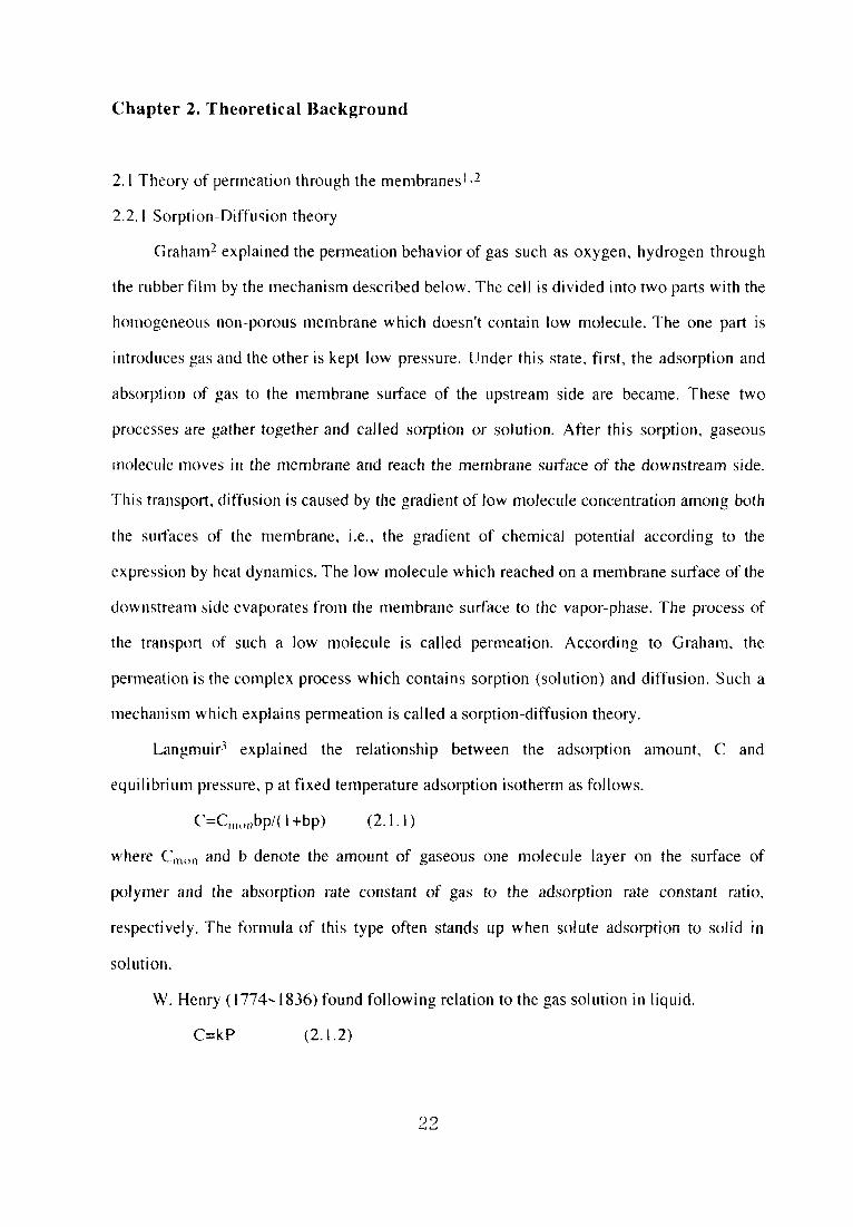
Chapter 2. Theoretical Background
2.lTheory of permeation throLlgh the membranesL2
2.2」Sorption-Diffusion theory
Graham2 explained the permeation behavior of gas such as oxygen, hydrogen through
the rubber film by the mechanism described below. The cems divided into two parts with the
homogeneous non-porous membrane which doesn「t contain Iow molecule. The one part is
introduceg. gas and the other is kept low pressure. Under this state, fi rst, the adsorption and
absorption of gas to the Inembrane surface of the upstream side are became. These two
processes are gather together and ca月ed sorption or solution. After this sorption. gaseous
tnolecu]e moves in the membrane and reach the membrane surface of the downstream side.
This transport. di ffusion iscaused by the gradient of low molecule concentration among both
the sulfaces of the membrane, i.e., the gradient of chemical potential according to the
expression by heat dynamics.The bw molecule which reached on a membrane surface of the
downstream side evap()rates from the membrane su rface to the vapor-phase. The process of
the transport of such a bw molecule is cal且ed permeation. According to Graham, the
permeation is the comp且ex process which contains sorption(so且ution)and diffusion. Such a
mec hanis m which explains permeation is cailed a sorption-diffusion theory,
Langmuir3 explained the re且ationship between the adsorption amount, C and
equilibrium pressure, p at fixed temperature adsorption isotherm as follows.
CニCnu川bp/(1+bp) (2」.1)
where Cln。n and b denote lhe amount of gaseous one molecu}e且ayer on the surface of
Polymer and the absorption rate constant of gas 芝o the adsorption rate constant ratio、
respectively. The formula of this type often stands up when soiute adsorptlon to solid in
SO葺utiOn.
W.Henry G774、且836)found fotlowing relation to the gas solution in liquid.
C=kP (2」.2)
22

where、 C and P denote the absorption alnount of gas alld equilibrium pressure. respectively.
This formula is cal且ed Henrys low and proportional constant, k is called a Hellry,s law
constant In sorption of gas to the rubbery alnolfus polynler, lt is thought that the absorption
is the predominant process and Henry,s low stands up.
2.L2 The basjc formula of the permeatめ11
When the diffusion is caused only in the perpendicular direction to the membrane, the
permeatioll behavior through the non-porous holnogeneous membrane is given by the
following Fick’s second low.
∂C/∂t=∂/∂x(D∂C/∂x) (2.1.3)
where C and D denote low molecular concentration and dげfuslon coefハcien重resρectively.
C=Co,0<x<1, t=0 (2.1,4)
Co is the early stage concentration,1is membrane thickiiess and the starting point of the x
axig. is a surface of the membrane of the upstream side. At x=0. when the permeatioll stalls,
CiS kept eqUilibriUm COnCentratiOn Cv=WhiCh COrreSp()ndS tO the preSSUre px Of the Vapor-
phase at once and this value continues for the measurement. For the measurement, the
sweHing of the membrane can be ignored and in the membrane surface on tlle dowllstream
side, concentration is kept at Co. That is, the boundary condition is as foHows.
C=C.,x=0, t>0 (2.L5)
C=Co, x=1, t>0 (2.L6)
By the condition that D isconstant, D=Do, and C,。〉>Co~O
Ql/(1 C。。)=Do t〃2-1/6-2/π2Σ(-1)・/112 exp(-D〔〕112 rτ2 t〃2) (2.1.7)
Qt is the permeation amount at the time t, when time t is long and the conditi()n is close to
steady state,
Qt=Doc。。〃(t-12/6Do) (2.L8)
The permeatlon rate Js under the steady state is defi ned as follows.
Js曇lim dQl/dt (2」.9)
1→つc
23

By eq.(2.1.8)。
Js=DoC。,/1 (2.1.10)
When it is supposed that the so量ubility coefficient of gas to polymer is S, the relation between
concentration Cっc and Pっc is given eq.(2」.1D
Cx=SPz (2.1.ll)
When S is constalltj.e. the sorption of gas to po且ymer is conducted by Henry’且ow of eq.
(2.L2)、 Js is shown by eq.(2.L12).
Js=DoS〔}p,c〃 (2.1.12)
When a product right side D(}and So is represented by Po, Po is shown as foHows from eq.
(2.1」2),
P(,≡DσSoニJil/p。σ (2.」.13)
Because Po is constant, it is called a permeabi且ity constant and it is calculated from the
gradient of the straight亘ine part of the permeation curve. The relation stands up under the
assumptioll of the constant diffusion coeffi cient D.
When D is a function only with concentration, i.e. the system is called Fick type、 the
relationships are introduced as follows4・s. Eq.(2.1.10)isshown as follows.
Js(C、。)=D(C。。)C。。/1 (2.1.14)
But, D(Cのis integral diffusion coef「icient.
e(:・.・
D(C。。)筆1/C・。 J o D(C)dC (2.1.15)
But, D(C)is the rnutual diffusion coefflicient which is a function with concentration. When D
depends on the concentration,重he sorption isother置n do not oftell become a straight line. At
this time、 g. ohubility coefficient S is defi ned by eq.(2.1.11). But differ from the case
following the law of the henry, S becomes a function with concentration(or pressure)and
the followiiig is introduced by eq.(2.1.14)。
P(Cx)≡D(C。。)S(C。。)=Js(C、,)〃px (2.1.16)
24

Pinthls equatbn is a functめn with concentration、 like D、 S. P(C。。)is called all meail
permeabihty coefficient. P(C、。)is found from the permeation rateし111der the steady state、
hke Po.
Permse置ectivity ofapolymer for gas A to B is argued by the ideal separation coe仔icient
αto define next. That is
αA〆Bミ(YAIYB)/(XAIXB) (2.1.17)
But, Xi and Yi denote the concentration of componel1重irepresented by the m()le fllaCtiOl}of
the upstream side and the downstream s孟de, respectively. When忙he pressure{》冨1 the
downstream side ls much lower compared with the pressure oll the upstream side, theαis
apProximately shown as follows.
αAIB=PA/PB (2.1.18)
But, Pi is the mean permeatめn coefficient of componenεi. Referring t{)eq.
(2.17),lt is possible to writeαdividing into two parts as follows.
αA〆Bニ(DAIDB)(SAISB) (2.1.19)
The ratio of the diffusion coefficient and the sojubiJity coefficient is called diffusion
selectivity and solubility se亘ectivity respectively, Diffusion selectivity is affected by the
physical factor Iike the polymer chain movement and the stuff condition of polymer segment.
On the other hand, solubility selectivity isaffected by the chemica置and phys孟cal interaction of
gaseous molecule and the polymer segment Permselectivity is often considered and argued
dividing into two pieces ofcontribution as shown in eq.(2。Ll9),
2.1.3Sorption
The kinetic property of sorption is described as f()llows. The sorption quantity to the
polymer membrane under the constant pressure increases in the time. Finally, it is saturated
25

alld reaches equilibrium sorption quantity. ln case of the diffusion that is one dimenslona監
diffusion with no volume change under an equilibrium temperature system, the diffus ioll of
sorpted moleculeisshown by the Flck’s second law as follows.
∂C/∂tニ∂/∂x(D∂C/∂x) (2.L3)
where, C, t、 x and D denote the amount of the sorpted molecules in the polymer represented
by the weight concentration(g/cm3), time, a distance to the direction of the diffusion and a
dift’tision coefflciel1しrespectively. The diffusion iscaused only in the perpendicular directlon
to the membrane jn consideration of重he very thiD polymer membrane compared with the size.
Because雨s supposed that the concentration ill the polymer membrane is homogeneous】y,
the concentration of early stage Ci at time O is given eq.(2⊥20)
C=C、 (一〃2<x<〃2、t=0) (2.1.20)
where. 1 denote membrane thickness. When the polymer membrane isしlnder the equilibriしコm
Jiqujd condjtion, the concentration of the membrane surface in the equivalent to the pressure
preaches the membrane surface concentration Cf。 immediately, That is
C=Cザ (x=±〃2,t>0) (2. L21)
[ncase that diffusion coefficient is independent of the concentration, eq.(2.L3)is soived
取mder the boundary condition ofeq。s(2.1.20)and(2. L21).
x
C(t)/C(○○)=レΣ8/{(2n+1)2π2}expl-D(2n+1)2π2t〃21 (2. L22)
where、 C(t)and C(QO)denote sorption amount at the time t and QO、 respectively. Relationship
between the amount of sorpted molecules C ill the polymer membrane under the hquid
condition over the glass transition point and pressure p is expressed by the Henry’s Iow
(eq.2⊥23)which is well applied to the absorption of gas to iiquid.
CニkDp (2」.23)
where kD denote a Henry,s law solubility constant. In the polymer membrane which is dohlg
lively segment exercise under equilibrium state、 sorpted molecules are homogeneousiy
dispersed in the s ys te rn. The foHowing is possible to confirm. By the fact that this membrane
is under the liquid condition, the sorpted amount and the pressure show straight line relation
26

and follow the Henry’s low.
The sorption gas to the polymer membrane under the glass condition is shown by
another sorption mechallism. When the polymer which has a b重of free volume and i9. doing
lively segment exercise is cooled and under the glass condition、 it has frozell free volt量me
(micro void). The po且ymer membrane under the g且ass conditioll collsistsく)f the part whe1’e
segment movement is frozen up and the part of above-mentiolled micro void, The former is
expressed by the Henrys sorption mechanism of eq.(2.1.23), the latter is expressed by the
adsorption of molecule to micro void, i.e. Langmuir’s adsorption mechanism. The sorption
mechanism is called a dua1-mode sorption mechanism, well-known as the s(}rption
mechanism of the polymer membrane under the glass collditioll and col甫rmed to fit actually
to the experiment6’ll.
C=kD p+CH・bp/(1+bp) (2. L24)
where CHI and b denote the hole saturation constant of Langmuir adsorptio11(related to the
quantity of micro void)and the Langmuir affi nity constant.
2.L4 Diffusion
When the interaction of diffusion molecule and the polymer membrane is strong, the
concentration dependence of the diffusion coefficient is well observed. When the
concentration dependence is small, the average diffusjon coefficient D is shown by the
foliowing equation apProximately.
D二且/C,∫[;tD(C)dC (2.1.25)
When the concentration dependence of the diffusion coefficient is changing to hulldreds or
thousands times high, the approximate method of the Crank has high precision. The
diffusion coef石cient Da in the early stages of sorption is given as follows.
Da(C,)。5/3α・・5∫lf C・・3D(C)dC (2.L26)
The diffusion coefflcient Dd ln the early stages of adsorption is given as f()Ilows,
27

、、t(C、)。1.85C、.1.・・flif
(Ct1-C)o・85D(C)dC (2」.27)
2.L5 Pervaporation
The pervaporation lsperformed as fo110ws. The feed solution is lntroduced one side of
the membrane and the other side was kept under the vacuum or flushed the inactive gas, and
Ihen the components permeate into the membrane, is vaporized and extracted. The sorption to
membralle, the diffusion in the membrane and volatility of the component a行℃ct the
permseleCtivity.
That is、 pervaporatioll is the method combined the membrane permeation and the
discreet dist川ation. The characteristic of pervaporation is shown be且ow.
(1)Because pervaporation does not need heating、 it can be apPhed to the separation
concentration of the therinal decomposition and thermal spoilage hquid.
(2)Because pervap()ration is different from the reverse osmosis and the ultra filtration which
is the same licluid separatjon method and needless to pressurize, the pressure densization of
the rnelnbrane is not caused.
(3)The isolation isn,t llecessary because penetrated material is obtained as pure material
ideally and isnot diluted differeTit frotn the dia亘ysis method.
(4)The membrane in pervaporation has the two Iayer structure which consists of swoHen
Iayer and the dense separation activated layer, because the feed solution is introduced one
side of the membra露1e and the other side is kept low pressure. This is one of the biggest
characteristics of this method and alollg with the characteristic of(2)that the pressure
densization is not caused、 isthought to be the favorable point fbr the permeation rate and the
nieinbrane hfetiIne,
(5)There are two way of pouring carrier gas and maklng a vacuum in pervaρoration. There js
a lirnit in the flow rate as the mass even ifthe flow on the capacity is made high、 because the
pressure of the permeate side is low.
(6)There is not an influence of the several atnl pressurization of feed solution but when
28

rnaking a degree of the deconlpression on the perIneate side higher. in apPropriate pressure
range, the permeate rate is increased by the decompression.
(7)The permeate rate is in reverse proportion to the membrane thickness. On the other hand、
the separation efflciency ls relationless in membrane thickness. The thickne∬of separatk》11
activation layer is relationless in membrane thickness.
(8)Pervaporation is useful separation process for azeotropic mixtures and ciose boiling
components which have different properties, for example、 polarities.
(9)lt is mentioned that the pervaporation is an effective separatioll method ill view of energy
balance when the feed concentration of objective componen重is below 30wt%.
Binningl2defi ned that the one part of membrane close to the feed soiulioll is a solutioll
phase and the other part of membrane close to the vapor side is vapol’phase. Whell
considering a membrane from the crossing direction. the most of the niernbrane is s(》lution
layers and is swoHen by feed solution. That is, in the solution phase the permeatk)n liquid
dissolves under the condition of so}ution. On the other hand. ill the vaPor phase the
permeation liquid is dispersed under the condition of steam. Up to now, generally, solutic)ll
phase is called swollen layer and vapor phase is called separatioll activated layer. AII the
processes of the separation by pervaporation are composed of the fdlowillg five pmcesses.
(1)The solution mo且ecules selectively dissolves to the membrane surface of the叩stream
side.
(2)After this dissolution, the molecule penetrates into the membrane.
(3)The penetrate molecules selectively dissolves on the boundary surface of the swolIen layer
and the separation activated layer.
(4)The molecules actlvely di仔use in the separation activated iayer.
(5)The molecuies which reached on the membrane surface of山e downstream side, adsorpt
and evaporate. The analysis of above mentioned process of the Enembrane separation is
extremely important to consideration of the characteristic。 the use of pervaporatk)11 and the
more required membrane efficiency.
ln vlew of the structure of the membrane, the physic and chemical properties(the
29

degree of the crystallization, polarity and so on)ofthe membrane are extremely important to
collsider the permeation. The chemical properties of the membralle affect the hydrophilicity
aDd hydrophobicity ba)ance of the membrane and infl uence on the permselectMty. The
hydrophi(icity and hydrophobicity ba置ance of¢he membrane can be adjusted by the chemicaj
modification, cross一且inking, co-polymerization、 grafting, hydrogen bonding and so o11. The
permeability isenhanced by the function groups in the polymer membrane which breaks the
combination ofρenetrates. On the other hand, the permeability islow in the membrane which
enhances the combination of penetra竃es. For example, the permeability of water is high in the
membrane with hydrophilic groups(-OH,-NH2,-COOH and so on)which brakes the
cluster of waters. However, the hydrophobic groups in the membrane increase the cluster of
waters and decrease the water pemleabilityB、LS. Also, the combination of the penetrates
depends on the properties of coexistent solvent and the temperature of solution16,17. The
control of the combinati()n of the penetrates can enhance the permse且ectivity. If it is supposed
1hat the components permeate through the polymer membrane followjng to the sorption-
difftis ion model、the process of the permeation is approximately divided to the three parts(D
the diss o且villg into the重11embrane of the components,(2)the diffusion in the membrane、(3)
Ihe ads《)rptjon outside the membrane.(D and(3)depends on the solubility of the
componellts.(2)is affected by the diffusivitity of the components. It is important for
separatk)n to utilize the difference of the solubility or the dlffusMlity of the componellts.
Also, whell the difference of both can be used ideally. the permselectivity can be more
enhanced.
2,L6 The basic formula of the permeation i重叩ervaporaion L2・18
The permeation ra重e of component i Qi is proportional to the concentration gradient of
the component i and shown by the following Fick’s first low.
Qi=-D(Ci)dq/dx (2. L28)
where D(q). Qi and q denote the diffttg. ion coefficient. the permeation rate and the liquid
concentration of the component i in the membrane at dis tance x from the membrane surface
30

of the upstream side, respectively.
The fick「s second low is given as fol塁ows.
dq/dt=D(q)d/dx(dq/dx)ニD(Ci)d2q/dx2 (2. L29)
Here. diffusjon coefficient D(Ci)is shown as fol]ows.
D(q)=Doexp(τq) (2. L30)
where Do、 T denote the dlffusion coefflicient a重concentratiol10and a constant which is the
standard of the plasticization of the membrane by the penetrali()n components、 depended c)n
temperature, respectively.
When the boundary condition of dG/dt=O in the permeation under the steady state.
Ci=q in x=O and Ci=C2 in X=1, the permeation rate Ji under the steady state is give置1 as
fo(iows by substituting eq.(2.1.30)for eq.(2」.30)and illtegratillg it.
Ji=Qi=Do/τ1(exp記rexpτC2) (2.1.31)
Also, the concentration distribution in the film is shown as foliows.
Ci=1/τln{expτCl-x〃(expτC【-expτC2) (2. L32)
If it is supPosed that the concentration oll the stlrface ofthe liquid alld the!nenibrane is
underthe equHibrium in view of heat dynamics, the following equation stands up.
ClニC*(po) (2」.33)
C2=C*(p2) (2。L34)
where C*shows a function, po and p2 denote the saturated steam pressure of s()lutioll and
the steam pressure on the downstream slde, respectively. Using these e(luations, eq.s
(2.1.31),(2.1.32)are shown by po, p2.
On the other hand、 permeation coeff[cient Pi isshown as fol】ows.
Pi=Ji〃△pニDo/τ△p(expτCrexpτC2), △p=p(Lp2. (2.L35)
When eq.s(2.1.33),(2.L34)are fo且10wing the Henryls law that are C*(p)=SP, eq.s
(2.L31),(2.1.32),(2. L35)become the function of po and p2.
Ji=Do/τ1(exp TS po-一一exp TS p2) (2.1.36)
Ci=1/τIn{expτSpo-x〃(expτSpo--expτSp2) (2.1.37)
piニDo/τ△P(expτSpo-expτSp2) (2・L38)
31

eq.(2.L39)suggests that it is not possible to consider with dividing a permeabihty
coefricient into the solubility coefficient and the diffusion coefficient in pervaporation
Considered to be the same as gas permeation. it becomes as follows.
Ql=一∫1㍉(G)dC、 (2.L39)
Qi=Pi(Pl-p2)〃 (2, L40)
where pl and p2 denote the steam pressure on the side of the high concentration and the side
of the bw concentration、 respectively.
eq.(2.1.4Dgiven by eq.s(2. L39)and(2.L40).
P、。{fi/i D(G)dCI}(P,.P,) (2⊥4D
By substituting this equation for eq.(2.1.42), the foHowing equation isgiven,
Ql.R.Pi(pトP、)=∫:了D(CりdG (2⊥42)
where R deIlote the ratio of permeatjon rate.
Whe雪i the concentration average diffusion coefficient Di is defined by the following
equation、 permeability coefficient Pi and the ratio of permeation rate R are shown by eq,s
(2」.44)alld formula(2⊥45), respectively.
D.∫:マD(G)dG/(CトC,) (2⊥43)
PiニDi{(Ct-C2)ノ(pl-p2)} (2.L44)
RF Di(Cl-C2) (2.1.45)
If the diffusion does not depend on the concentration of the permeation component、 Di may
be the diffusion coemcient D、
For the permeation in pervaporation. by pl>>P2, eq.s(2.L43).(2.L44)and(2. L45)
are sllown as foliows.
32

、、、=∫1?iD(C、)dC、/G
Pi=Di(Cl/Pl)
(2.L46)
(2.1.47)
R=DiCl (2.L48)
When Ct /pi js assumed Si(apparent solubility coefficient). the following equatiく)n isgivel1.
Pi=DiSI (2,L49)
lt is possibleto show permeation coefficient Pi as the product the concentration
average diffusion coefFicient Di and the apparei】t so置ubility coef備cie置lt S l.
In pervaporation, also, the permeation rate can be described by collsiderillg the gradient
of chemical potential(μ)to be the drMng fbrce. Tentative illustration for the permeatioEl〔〕f
pervaporation is glven in Fig.2」」t is possible to show the permeatioll rate(〕f coMi)ollel}t i
as the product the concentration, the degree of the movement m, and Ihe drMng fol昌ce as
shown ineq.(2.L50)folJowing to the sorption-djffusjon theory.
Qi=-Cimi(dμ/dx) (2.1.50)
mi=Di,T/RT (2.1.5D
Where Di,-r denote the heat dynamic diffusion coefficient.
The concentration in the membrane is not being constant to the direction()f the
membrane thickness, and it pictures a gentle curve and decreases in the direction of the
permeation flow. The heat dynamic equilibrium is formed on the sur飴ce of the membrane
and feed solution, that is, it s叩poses that the chemlcal potential of the component i()ll the
surface of membrane in feed side is equal to the chemical potential of the component i iII the
feed solution ( μi、1ニμi,o), In the case, it is considered that the concentratjon of Ihe
component i in the membrane in the upstream side can be detected by the sorption
equ川brium measurement. When the dissoiving becomes later than diffusing because of the
resistance, i.e. the concentration polarization in the liquid boundary phase, the concentration
33

in upstream side of membrane is often lower than the equilibrium sorption concentration in
membrane. When membrane thickness is thin, this resistance increase. As the concentration
of one componellt in feed solution is very bw and the permselectivity for the component is
high、 the concentration polarizatlon iseasjjy caused.
Liquid…
Membrane Vapor…… Ci,1
…三
μ1,1
Ci,o
…
ハiゆi/ゲ
@ …
P2
PO
……… Ci,2
μi,v Ci,v
… μi2/ヲ
…
≡ X≡≡ ⊥
Fig.2.l Chemical potential gradient fbr preferentially permeathlg component across the
豊nernbralle,
The degree of the(mole)movement of Iow mQlecule mi shown by the eq.(2.L5D
contained Di.T,Di.T is related to the Fick diffusion coefficient by the foHowing eq.(2.1.52).
Di=DL・i・(In al/ln Ci) (2. L52)
En isotherm. chemical potential is given by a function with activity and pressure. Chemical
poteIltial for conlponent i is given by eq. (2,153). lncidentally, ai is activity of the
component 1.
34

μi=μLo+RT ln ai.+Vi(Pi-prcf) (2. L53)
Where Viis a partial molar volume of componei〕t i. pi are the presg. ure of the component i.
Therefore, the driving force in the direction of the Inen、brane thickness, Le. ill the directioll
ofthe x axis becomes as follows.
dμノdx=RT(din ai/dx)+Vi(dpi/dx) (2. L54)
The pressure term of eq・(2・1・54)can be omi重ted becaIlse dleρre∬ure di ft-e ret]ce between the
upstream side and the down stream side is about l atm and it is RT△Ill ai>>Vi△p, ill usual
pervaporatlon.
Thereforejt is possible to show driving force as fonows.
dμi/dx=RT(dIn ai/dx) (2. L55)
Consequently, the permeation rate of the compo!】ent i is shown by the fbllowillg eq.
(2.L56).
QF-cl Di.T(dln ai/dx) (2. L56)
This relationship is the equation which is often used to consider the permeatk)n niodel
through the homogeneous membrane.
The permeation rate Ji under the steady state can be expressed as follows by Fick’s
flrst law(2, L28).
Ji=Di(Ci,1-Ci,2)〃 (2.L57)
Ci,1ニKi.ICiρ (2.L58)
CL2=Ki.2q,v expl-Vi(Po-P2)/RTi (2. L59)
Where Ci、land q.2 denote the concentration of component i on the membrane s uri’ace of the
upstream side and the downstream side. q.〔〕and q.v denote the concentration of c()mponellt
iin the feed solution and the vapor side. Ki is the partition coefficient. Vi is a partlal inolar
voiume of component L Po and P2 are the tota】pressure of theしjpstream side and
downstream side。
The臥1-Vi(P〔}-P2)/RTi becomes very smal1, and the exponentiaherm becomes nearly equaI
to 1.
Ci.2=・Kl.2 q、、 (2. L60)
35

The activity of downstream side ofthe component i, ai、、, is given as foHows.
ai.、,=Yi.、 Ci.、ニPi.2/p°i (2.L6D
Where pi.2 and p「denote vapor pressure of the component i in the downstream side and the
saturated v a p or p re s. g. u re of component L Yi.Y is activity coefficient of downstream side of the
compOIlent L
pi.2 becomes nearly equa且to O when the pressure of downstream side is c且ose to O. Then, the
concentration on the downstream side(Ci.、)is almost O. In case of pervaporation,adsorption
is comparatively fast caused and the concentration in membrane on the downstrealn side
(q2)isalm⊂)st O. eq.2.157 becomes
JFD,Ki.lq.o〃 (2.L62)
Where
Pi=Dl Ki.} (2.L63)
Ji=Pi Ci.o〃 (2.1.64)
This relationship is the equation which is often used to consider the permeation of
pervaporatioll throしlgh the homogeneous membrane」n this study, thls equation is used as
basic equation.
2.2Graft poly智nerization l 92〔}
2.2.ISi置nultaneous irradiation
A.Rabee. G. Odian et. aL20,0ffered several possible grafting mechanisms in
simultaneous irradiation. The dependence on monomer changes with increasing does rate as
does the dependence of grafting rate on does rate. The initiation of graft polymerization
involves the involves the formatlon of primary polymeric alkyl radicals(P・)by radiolysis of
the polymer(P):
P-radiation→P・ (2.2. D
followed by addition to monomer to fbrm the propagatjng radica量:
P・+M-ki→M・ (2,22)
Propagation can be depicted in general terms as
36

Mn・+M-kp→Mn+1・ (2.2.3)
AssumiDg that terminating occur by bimolecular coupling and/or disportionation of
propagating radiation as followsl
Mn・+Mm・-kt→dead polymer(2.2.4)
This wm occur, however, only if the primary radicals undergo a destructive 9. ide reactio盲1
with some species Z:
P・+Z -k2→ destruction of primary radica璽s (2.2.5)
Reaction(2.2.4)may involve reaction with other radicals or with some inhibitoi’
present in the system or the conversion of the primary alkyl radicals il】to unreactive alkyl
radicals(via successive hydrogen abstractions toward unsaturated groups present initially ill
the polymer or formed during irradiation)\or some other reaction.
Under these conditions, the initiation rate is the rate of eq.(22.2):
RiニkilP・1[Ml (2.2.6)
On assuming a steady state in the concentration of primary radical I P・1, Le., that the rate of
formation of primary radicals eq.(2,2.1)equals their rates of destructloll eqs.(2.2.2)and
(2.2。6),yields
kllPIG1=k21p・llz1+kilP・11M1 (2.2.7)
The left-hand side ofeq.(2.2.7)is the rate of eq,(2。2.Dwhere G is the G valve for
primary radical formation(number of radicalsformed per lOOeV)j isthe radiation dose rate,
and kl is a constant which includes various conversion factors such that k l lPIGI w川have
units of moles per Iiter-second as do the other rates.
solving eq.(2.2.7)for ip・land substituting into eq・(2・2・6)yields Ri as
Ri={klkilMllplGI}/{k21Zl+kilMl} (2・2.8)
In the usual case kilMI>>k21Z1, the initiation rate Ri is independent of monomer and the
grafting rate Rp is given as fbllows
Rp・kp岡(Ri/2kt)1/2 (2・2・9)
The concentration of primary po}ymer radicals is given by iP・i=KIPIwhich, when combined
37

with eqs.(2⊥63)and(2. L65), yie)ds
Rp=kplMKKkilPllMl/2kt)1/2 (2.2.10)
for the rate of graft polymerization.
The acωal mechanism for the lowered rate of monomer addition to primary
radicals relative to recombination of primary radicals may be due to the monomer
concentration not being sufficiently high. ln the systems. the polymerization rates decreased
in proportion to the decrease in monomer concentration as monomer was diluted with solvent
un田acritical low monomer concentration was reached. After that critical monomer
concentration, the polymerization rates decreased much more rapidly than expected based on
asimple dilution effect. The situation involves the competition between reactions(2.2、1D
and(2.2.12):
P・+P・or P・+H・→ primary radica且recombination (2.2」1)
P・+Mor H・+M→initiation (2.2.12)
Since inhib面on is monome卜dependent while primary radical recombination is monomer-
independent、 the later becomes increasingly more competitive as the monomer concentration
decreases, Interestingly. this critical monomer concentration was reached earlier(Le., at a
higher concentration)as the radiation dose rate increased.(ls it a coincidence that the order of
dependence of rate on monomer in the system increases with increasing dose rate.)The
competition between reactions(2。2.11)and(2.2」2)favors primary radical recombination as
the dose rate increases、 since that process is second-order in the radicai concentration while
illitiation is only fi rst-order, Above the criticai monomer moiecuies to scavenge all primary
radicals which begin to difference from their cages. But below the criticat monomer
concentratjon, this is no longer the case and pri mary radical recombination becomes
Hnportant
An energy transfer mechanism invo且ving energy transfer聾nay be responsible for the
increased orders of dependence of rate on monomer. Such energy transfer eq.(2.2」3)
completes with the f()rmation of pri mary radicals eq.(2.2.14).
38

P-radiatbn→P*-B→ P+B*→energy dissipation by B* (2.2.13)
P・-M→initiation (2.2」4)
Here P and S are polymer and solvent, respectively, P*and S*are the corresponding excited
species, and M ismonomer. Energy transfer results in a decreag. e in the rate of illitiatiOl). The
extent of energy transfer increases with the concentration of benzene. Thus、 the initiation rate
is inversely dependent on monomer concentration.
For excision energy transfer, the initiation rate would be first order in nlonomer, i.e.、
Ri oc 1ノ(energytransfer)(x r3 Q(1/1BI oc IMI(2.2.15)
For energy transfer by the F6rster mechanism, one would predict a secolld-order dependence
of the initiation rate oll monomer:
Ri α 1/(energy transfer)㏄r6 ct l/1BP ct IMI2(2.2.16)
The energy transfer from exited polymer to monomer would result in a dependence of the
initiation rate on monomer、 yie置ding a higher order of energy transfer would depend o旧he
mechanism of energy transfer.
The dose rate increases indicates that the mode of termhlation is changing frOlll the
usual bimolecular coupling and/or disproportionation of propagatii】g radicals
M・+M・-kt→termination (2.2.17)
to reaction of a propagating radical with a primary radical
M・+P・-ktO→termination (2.2.18)
The Iatter reaction is referred to as primary radical termination and has been observed ill
homopolymerizations of monomer carried out in high vis cosity media. Further, as Chapiro
pointed out, primary termjnation becomes increasingly important at high dose rates as the
concentration of primary radicals increase. Primary termination may be especially important
in high viscosity systems(such as a grafting system)where primary radicals would have
grater mob浦ty than the larger-sized propagating radicals.
The kinetics of polymerization where termination occurs exclusively by primary
te㎜ination置ead to the expression for the graft rate
39

Rp=kpkilM)2/ktO (2・2・19)
which shows the grafting rate to be second-order in monomer and independent of dose rate.
G.odian et aL21.studied the case of graft polymerization proceedlng in a po】ymer fi】m
of thicklless L in l〔}0%monomer by simultaneous irradiation method.
The other two dlmens孟ons of the film are large relative to L such that only two-sided
(one-dimensional)diffusi()n need be consideredちdiffusion of monomer from the four edges
(,fthe flim are relatively unimportant. Applying Fick「s second law ofdiffusion、 one obtalns a
lnass balance oll the monomer contained in a thickness of infinitesimal size within the
polymer飼mas
Rp+(dc/dt)ニD(d2c/dx2) (2.2.20)
wh・・e Rp i・th・・at・・f m・・1・m・・di・・pPea・ance(i・e・・9・aft p・1ym・・i・ati・・)i・th・t thi・kne・s・
dc/dt is Ihe change in the monomer concentration in that thickness with time and D(d2c/dx2)
isthe difference inthe rates of diffusion in and out of that thickness. In eq.(22,20), x is the
distance from the center of the film, c is the concentration of monomer in the f1 1m, and D is
出ediffusMty of the monomer wlthin the polymer.
h1 Ihe usua}grafting experiment, the polymer and monomer are equilibrated prior to
irradiation、 After equilibration and prior to the start(time=0)of the irradiation, all of the
terms in eq,(2.2.20)have valves of zero throughout the whole film thickness. The monomer
concentration is its equilibrium or maximum valve M and is the same throughout the whole
film thicklless. The situation changes quite drastica11y with the start of the irradiation. The
rate of graft polymerization very quickly(almost)instantaneously)reaches a maximum valve
and then begins to fati as the monomer concentration(responced by dc/dt)decreases.
Diffusion of monomer occurs simultaneous as the Dd2c/dx2 term increases with time from
its zero value. Finally. the monomer-polymer system reaches a steady-state condition in
which the monomer concentration and grafting rate become cong. tant and independent of
time. The dc/ct term is zero at steady state, and eq.(2.2.20)becomes
Rp=D(d2c/dx2) (2.2.2D
40

The steady state of the grafting system does not imply that the monomer concentraUon
and grafting rate are constallt and uniform throughout the whole thickness of the polymer
film. both of these quantities show a distribution profile throughout the film thickness with
maximum values at the佃m surfaces and minimum vahues in the center of the f’ 堰@1 m. The
steady state refers simply to the fact that monomer concentration and Rp profiles have
reached constant valves and do not undergo further challges, The MOIIolner collcentratlon
and grafting rate at any thickness of diffe rential size in the filrn are collstallt.
From ordinary free radical polymerization considerations, the grafting late at al)y
differential thickness in the伺m w田be given by
Rp=(kp/ktl/2)Rii〆2c (2.2.22)
where Ri is the rate of initiation(i.e., radical production inthe poly置ner)and kp and ki,1・1’e重he
rate constants for propagation and bimolecular termination. Combination of eqs.(2.2.1)and
(2.2.22)yields as foliows
d2c/dx2=1(kp/ki1/2)(Ril/2/D)lc (2.2,23)
Two boundary conditions(BC)must be satisfied by eq.(2.2.23).
These are BCI:at x=0, dc/dx=0 (2.2.24)
BC2:at x=L/2. c=M (2.2,25)
The first boundary condition states that there is no concentration gradient at the center of the
polymer創m since diffusion from both sides meet at the center thickness, The second
boundary condition states that for a創m of thickness L. the monomer concelltration at the
surface isequal to the equilibrium concentration M.
One should note that the experimentally determined grafting rate is not Rp but is instead
the average volumetric grafting rate Rp averaged over the enti re thickness of the polymer
film. The average grafting rate is thus given by
Rp。(2/L)∫1’2 Rpd、(2。2.26)
where Rp is defined by eq.(2.2.22).
41

Combination and rearrangement of eq.s(2.2.21),(2.2。22),(2.2.26)yie畳ds
Rp=1(kp/kj 1!2)Ril/2 M)1tahnA/A (2・2・27)
where
A=1(kp/kil/2)(Riレ’2/D)11t2 L/2 (2.2。28)
Equation(2ユ27)shows the general relationship among the qしlestions Rp, Ri, M, L,
kp/kiu2、 and D and can be used to interpret and analyze experimental data in grafting
sys tems. Equatiol1(2.2.27)can be meaningfuliy expressed in a graphical manner by a log-
log plot of Rp versus A. This is equally applicab且e to all polymers and monomers under all
conditioi)s of initiation rate、 film thickness and reaction temperature. The Ri valve is
determined by the radiation intensity and the G valve of the monomer. The valves of M、 D,
and kp/ki i ’”2 are determined by the particular combi nation of polymer, monomer, and
temperature. The average grafting rate Rp is then determined by the film thickness and all of
the parameters inaccordance with eq(2.2.27). Equation(2.2.27)has defined by the values
ofA。
2.22PreirradiatioI、
ln bulk polymerization using preirradiation method, polymer radicals are terminated
mc)stly by coupling, and the contributions of chain transfer to monomer and
dispr()portionation are significant22. lt is considered that the ratios of coupling ill grafting
reactkms are identical with those of bu且k polymerization. It is quite difficult to estimate the
apparent chain transfer constant in heterogeneous systems. The fact that observed values of
Mn of grllft chains are terminated by co吐lphng2〔}. The nature of coup亘ing processes of graft
radicals may appear to be quite different from that of homopolymer radicals in solutions;
sillgie ends of graft radicals are tlxed on the trunk polymer end、 consequent}y, the
transitional diffusion of center of masses is hindered. The rate-determjnjng s重ep in coupling
42

reactions between polymer radicals is not the transitionai diffusion of theircellter of mass but
the segmental motions of active ends around the chain centers。 Hence. it would be probable
that the coupling Probability of graft radicals is influenced by chain且ellgth iII ways somewhat
similar to homopolymer radicals in solutions. The molecular weight distributionく)f gmft
chains is one of the most important factors in characterizing graft copolymers. The detail
several factors which influence the molecular weight distribution of gr乏盈ft chains was studied
by simulating the grafting reaction with various models emp置oying M(mte Carlo紅echllique by
T.Yasukawa et al22.
Moreover, the bulk polymerization using preirradiation meth叱)d is affected by the
reaction temperature, the physlc and chemical propertles Qf InoIlomer. and the affillity of
monomer to polymer like as simuttaneous irradiation i 9.
2.3Moiecular dynamics for aqueous solution
The mo且ecular dynamics of Iiquid water is interesting and imp()rtant ill mally areas of
sciences. The scattering of X-rays from the free surface of liquid water in equihbriu111 with
water vapor has been analyzed by A. H. Narten et aL23、 The thermodynamic propelties
estimated fbr the model structure are in essential agreeme猷with those of liquid water. The
X-ray difrraction data on liquid water presented the yield information on the average atc)mic
arrangement around any oxygen atom taken as the origin. The water model retains the
hexagonal symmetry of the ice-1ike network. The model has properties which are not ill
disagreement with the thermodynamic properties of water, and it may be he畳pful巾the
interpretation of the many strange properties of water. D. F. Coker et al.24, present the
results of using infrared predissiciation spectroscopy based on bolometric detection to study
clusters of water moiecules. The clusters are formed by expanding water vapor in helium
from a wide range of source pressures and temperatures。 Measurements are made using a
color center Iaser as the source of infrared radiation alld a cryogenic bolometer as detector。
This method has proven very useful for a wide range of van der Waals clusters23 and has
43

glven rovibrationai spectra and estimated predissiciation llfetimes for several dimmers、 by
varying the source conditions it is possible to identify the dimmer vibrational modes and
watch their transformation, as the cluster size increases, towards the type of vibrational
spectrum found in liquid water. The combined intra-inter molecular potential surface
indicated an excellent description of water dimmer and trimmer vibrational frequencies. By
postulatioll of pair wise additive potentials between rigid water molecules and molecular
dynamjcs techniques on a system of a few hしmdred molecules the structural and dynamical量y
correlation in pure water has been studied23・24・25. The resuit of all these studies has been to
show that the water structure can be thought of as a network of hydrogen bonds. These
hydrogell bonds are Ilot perfectly formed as ice crystaL Uniike the case of ice crysta且sjn
liquid water, one is requlred to set down a”definition”of a hydrogen bond. A. Geiger et
aL24, simulated the molecular dynamics for liquid water。 Water has to be consldered as a
large macroscopic space-fi且ling network enclosing a few small bonded but isolated clusters.
0,Ya. Samoilov26 mentioned the exchange of water molecules in the immediate
vicillity of the ions. A11 examination of the action of ions on the transitional motion of the
water molecules closest to the ions may be offered as a basis for a general approach to the
study of iOll hydra!io喜1 in aqueous solutions. The properties of aqueous electrolyte so】vt}OllS
depend ill匿arge measure on the interaction of ions with the molecules of the water. This
illteraction is known as the hydration of ions and extreme且y important both for the
equilibrium properties of sohltions and for properties that are known as kinetic propertles
(viscosity. diffusion, etc.). When studying the hydration of ions it is common to consider
iolls as bonding a certain number of water molecules of the sohltion. Attempts have been
made to describe hydration in terms of the number of water molecules bound to ions, the so-
called hydration mlmbers. The entire total effect of hyd ration of ions may be divided into two
parts:”prilnarジhydration that consists chie刊y in the firm binding of the water molecules by
the iol1;and,’secondarジhydration which amounts to the polarization, due to the action of
the field of the ion、 of the water not included in the primary hydratlon. An examinatjon of the
action of iolls on therma}agitation and above all of the so-called transitional motion of the
44

water moJecules of the solution dosest to the blls may be offered as a basis for such a
general apProach to the sIudy of ion hydration i置1 solutions. The transitional motion‘)f water
molecules relative tQ the ion in its immediate vicinity should be regarded as the exchange of
water molecules of the solution that are cbsest to the i(m. If the exchange occurs relatjvely
rarely, the hydration of the ion is considerable. As the frequency of the exchange grows the
hydration of the ion weakens. The magnltudes defining the frequency of excl沿nge of water
molecules near the ion are, according to the suggested point of view、 the quanti tati ve
characteristics ofめn hydration in sotutiolls. Water molecules a{’e always movitlg, The
motion of water motecules in an aqueous solution containing a soiute isaffected by the wa¢er
and solute interaction, and differ from that in pure water. This interaction(the watel’
hydration of a solute)is important for the klnetic properties of a solution. For pure water.
the water molecules exchange in the vicinity of each other almost immediately. Tile me三ul
time in an equilibrium position is denoted asτ. The value of the activati()n energy of the
exchange is denoted as E. ln the case of an aqueous solution、 the mean time that a water
molecu且e is in the closest equilibrium position to the ioll in the structure of the solution is
denoted asτi, The value of the activation energy of the exchange of the closest molecules is
denoted as E+△Ei. The foHowing relation is then obtained 26・27.
τi/τ=exp(△Ei/RT) (2.3.1)
In the case that the solute is an organic compound, the interaction between water mdecLIIes
and a hydrophobic group or a hydroρh術c grouρis as follows:
△Ei=△El+△E2 (2.3.2)
The activation energy of the exchange of the water molecules connected to hydrophiiic group
is denoted as△E1.The activation energy of the exchange of the water molecules connected
to hydrophilic group is denoted as△E卜When△Ei>O is the magnitude of the ratioτi/τ>L
i.e., the time that the water molecu且es connect in the vicinity of a solute molecule in the
solution is longer than the time adjacent to the vicinity of a w飢er molecule in pure water・The
motion of the water molecules are prevented by the solute vicinity. When△E}<O and the ratio
τi/τ<O, the water molecule adjacent to the sdute becomes more mobile than in pure water. ln
45

the case of an aqueous solしltion of organic compounds、 generally、 the water molecules
adjacent to the solute becomes Iess mobile than in pure water.
Hydrogen bond formation of water molecules in aqueous solutions is thought to form
clusters with”ice-1ikeサI structure that are stabilized by the presence of a hydrophobic group25。
Pauhng28suggested that hquid water has a structure, or range of structures、 which consist of
aframework of ordered water to contain non hydrophilic molec田es in the voids. Liquid
water can be regarded as a”water hydrate.”consisting of some such framework as is found
in the clathrate crystals. which the enclosed sites occupied by unbonded water molecules.
The frameworks inquestion may be thought of as based upon a pentagonal dodecahedron of
20water molecules, each participating in3hydrogen bonds、 one such bond lying in each of
the 30 edges ofthe solid figure. The inside of such a dodecahedron contains a void of about
5入immobstructed diameter, These are”large”voids(6 A or more of free diameter). as
contrasted with the”smalr, ones in the dodecahedra. The properties of enthalpies and
elltropies which are derived for framework and interstitial water, respectively、 also seem
physically reasonable29. H. S. Frank et a128, gave a statistical-thermodynamic treatment to
Pauling’s model for liquid waten ln liquid water, some molecules be in a”third state,”and if
this third state is take冨1 into consideration the shortcomings of the simple mode且can be
renledied.
On the basis of a quantitative assessment of the hydrophobic effect from the standard
free energy, enthalpy、 and entropy of solution of a large number of gaseous Ilon polar non
electrolytes, The hydrophobic effect that arises through a methane group in n-alkanes is
primariIy all enthalpic effect that arises through a methylene/water interaction30. On the other
hand、 polar solule species with hydrogen bonding abiiity are also expected to show enthalpy
changes for solutes in water. By N. Nishi et aL30, Stab川ty of hydrate clしlsters in aqueous
sotutiOll has been studied.The hydrophobic effect of a methylene group was evaluated on the
bαsis of the quantitative assessment of the hydrophobic effect from the standard free energy.
enthaipy, and entropy of solution.On the other hand, the hydrogen bonding ability of a
polar solute was also studied. The trend is observed that ethanol-ethanol association is
46

attributed to the hydrophobic hydration of an ethyi group of an ethanol nlolec111e ill aqueous
enVtronment.
The decreases in entropy is due to the tendency of the water dipoles ill the Iayer of
water adjacent to the hydrocarbon solute to orient with respect to the dipoles in the water
molecules in the next water layer. This effect does not exist ln the bulk hqし且id away from a
surface or hydrocarbon mo亘ecule because of the symmetry of the electric field ill which a
given water molecule finds itself. According to this theory、 then、 the mmber of water
mo且ecules that can be packed around the hydrocarbon molecule is an impo!tallt cluMltity iluhe
partition function for the hydrocarbon solution. ln view of hydrophobic b()nding, also used
this number of water molecules in the fi rst water layer as being a factot’in hydrocarbon
solubility-3 1.The number of water molecules that can be packed around a given hydrocarbく)11
soiute molecule is depending on the soiute conformation and the assumed water structure.
The number is related to the surface area of the solvent cavity if the surface is defilled in sucll
away that itρasses though the centers of the water molecules mome童itarily adjacent to the
sotute. This idea of cavity surface、 whiie slightly idealized、 can be more easily caicula(ed.
For a spherical cavity the free energy△G for transferring a molecule from the gas phase to
the solvent is approximated as foHows32.
△G=4πr2σ一ε (2.3.3)
where r is the cavity radius,σis the soivent surface tellsioll. andεis tlle sokIte.s()tvent
illteraction energy. Then c7c、 the ratio of molecules in the sdvent to molecules in the gas
phase, isgiven by the Boltzmann distribution
cソcニe-△G!kT (2.3.4)
Since that time, the liner relationship between the solvent surface tension for non polar
so且vents and the logarithm of the gas solubihty has been amply verified. R. B. Hermann3L32
studied the correlatlon of hydrocarbon solubility in water and the free energy change with
solvent cavity su㎡ヨce area, The free energy was assumed to be linearly related to the number
of water molecules that can be packed around a given hydrocarbon molecule. The cavity
surface area is a better parameter than experimental moiar volume in correlating s. olubilities.
47

The hydration number of water molecules is what can be packed around the partition function
for the hydrocarbon solution. The hydration number of water molecules wiH depend on the
soiute conformatjon and the assumed water structure. The hydration number is also related
to the surface area of the solute that passes through the centers of the water molecules which
can be affixed to the solute. The bulkwater is the water molecules that are not adjacent to the
solute and have no Interactlon ,
The solutes in aqueous non electrolyte sotutions may be derived into two classes
accordhlg to the predominant thermodynamic property in the mixing process with water26.
These are termed typical置y aqueous and typically non aqueous. The former solutes are those
which exhibit in solution anomalous thermodynamic properties as found only in aqueous
sojUtiOII and are typified by relative magnitudes of excess enthalpy△H and excess entropy
TδSin such a m段fmeras IT△Sl>i△HI(e.g.. alchols and amines). On the other hand, the Ietter
solutes in aqueous solution indicate the properties which are similar to those of normal non
aq ueou g. solutes and the relation between the two thermodynamic functions is characterized
as l△HI>IT△Sl.Therefore. it is possible to interpret the thermodynamic properties in terms of
direct interaction between water and so且ute molecules in the case of typically non aqueous
solution. However, those of typically aqueous solution are for the most part attrlbuted to
change of water structtIre aroしmd solute molecule rather than the interaction between wa重er
and solute. Especially. structualization of water by incorporation of non polar molecule th飢
belongs to typically aqueous solute is called hydrophobic hydration27・33. This phenomenon
is accompanied by large entropy loss and negative enthalpy change in the course of
hydration. It was confirmed explicitly that hydrophobic hydration at infinite dilution and
hydrophobic interaction at higher concentration play predominant roles for the molecules
having both polar and non polar groups. This fact could be predicted by thermodynamic
measurement. They recognized sQ many hydration phenomena of non electroiyte solutions
are related to the hydrophobic hydration or interaction. Moreoverjt is difficult to obtain the
microscopic structし書res or energetic interaction distributions from ordinary experiments but
they can be related to macrog. copic or thermodynamic properties by computer simulation. By
48

K.Nakanishi et al・34・Monte Carlo ca且culatio1】s have been carried out for an in伽itely diiしlte
aqueous solution of tertlary butylalchol(TBA). The bu且ky tertiary aiky且group of TBA can
occupy cavities in the network structure of water effectiveiy. While such targe vo(t“me
contraction at infinite dilution of TBA is mainly due to cavity effect. there is a further
contributlon from hydrophobic hydration. This is more clearly seen by cotnparing the pa函al
molar enthalpy at infinite dilution which is more negative than¢hat for methanol. Thls is
attributable to the hydrophobic hydratlon of the l)oll polar group which is larger in TBA. The
hydrophobic hydration at infinite dilution may be characterized by a large llegative tertninal
value of partial molar excess enthalpy as the extension of its rapid decrease in dilu1e aqueous
solution. Excess enthaipy data fbr the water-TBA mixture indicate that dle dissolution(}f
TBA into water is exothermic in dnute solutbn and teIlds to be p〔,sitive ill the TBA rich
region. The introduction of one TBA molecule into pure water Ieads Io shift of重he
equilibrium. ifthe hydrophobic to hydrophobic ratio in the molecute is large, tllere will be a
Iarger volume decrease. This is the hydrophobic hydration effect of hydrophobic groups to
promote effective cavity filling. This effect seems to be especially large when the molecuie i塞、
question has methy且groups. By H. Tanaka et aL35、 a molecular dynamics calculation oll
aqueous solution of urea has been carrled out using constant temperature technique and
Monte Carlo ca且culation. Instead of the possibility to form strong hydrogen bolldillg as
estimated from the potential function, it is found that urea mo)ecule could enter hlto the water
structure without any appreciable distortion. Thls fact was conflrmed by the angular
dependence of any distribution function around the urea molecu匪e. The hydrophi且ic region
does not show a large energetic stabllization between water molecuies and the system is
stabihzed slightly by including urea-water interaction. In contrast to this, the energy for water
molecuies in the hydrophobic region(above and bellow the plane contalning urea molecロ}e)
becomes bwer than that of pure water. although this region is small and water molecules
cannot fbrm a strong hydrogen bond with urea. This fact reveals tha1 the role of each
functional region, which may be either hydrophobic Qr hydrophilic, is similar to that of
alcohol in aqueous solution, aithough the whole hydration structure of urea molecule is
49

somewhat different from that of alcohol. Reflecting strollg interaction of urea-water. the
diffusion coefficient for sheil water molecules in the vicinity of urea. Moreover, the
hydration structnre around urea continues for a long times, though the energetic re且axation
time is very short. R. A, Kuharski et al.36, also studied the effect of urea on water structure,
Only very small differences are obtained between the properties of water molecuies in the
solvate region of urea and bulk, and these difference can be assigned to direct urea-water
interactions, with no substantial perturbation of water-water interactions. There are only
smalldifferences between water in the vicinity of urea and bulk water, and furthermore, that
these sma“differences are the reseai of direct interactions between urea and water molecutes
with n《)substantial urea一量nduced perturbation of water-water interactions. The quantitjes
collsidered, including bonding energies, pair interaction energy distributions, and hydrogen
bondi”g, show that water mo且ecules in the solvate shell of urea have properties which are
very Similar to those ot” buikw飢er. Urea has Iittle effect on water structure, ill contact to the
inference from several experiments that urea acts as a water structure breaker.
Thus. the solしlte ill aqueous solution effect on the molecu且ar dynamics of the around
water alld the physical and chemical behavior of the solutlon.
2.4References
DThe society of Po且ymer Science, Japan, Shin koubunshi Jikkengaku(experimental method
ill polymer science voL IO;in Japan, Kyorltsu press Ltd..Tokyo(1995).
2)The society of Po且ymer Science, Japan, Koubunsi tho mizu(Polymer and Water);in
Japan, Kyoritsu press Ltd.,Tokyo(1995).
3)匪.Langmuir. JF. A〃~. Chem. Soc..40,且361(1918).
4)CE. Rogers. iバPhisics alld Chemistry of the Organic So[id State‘「, VoL2, D. Fox, M.
L.Labes, A. Weissberger eds., John W川ey&sons,1nc,, New York,1965、 chap.6
5)H.Fuj i ta、 Fで,r’.s’(’hr。〃o(°hpolstn.-Forsh.,3,1(196 D.
6)T.A. Barbari.WJ. Koros. D.R. Paul, 」. Pで,1v〃~. Sci. Part B, Plv〃1. P乃v5.,26,709
(1988).
50

7)SA Stern. G・R. Mauze, H.L Frisch、ノ. Poムw~.∫(ゾ. P()ム・〃7. Pんw. Ed..21,1275
(ig83),
8)S.-M.Fang, S.A. Stern, H.L. Frisch, Che’Tl. E’~g,∫ぐ1.、30、773(1975).
9)S,A. Stern, S.-M。 Fang, H.L Frisch,ノ. P‘星v〃~. S(で.!レ2. IO.201(1972),
10)M.L W川ams, R.E Randel. J.D. Ferry、ノ.んη.α1ピ〃1。∫θ(㌧.77,3701(1955)。
ll)』D. Ferry-Mscoelastic Properties of Polymers’°,3rd edn..chap. l l,」(,hll Wiily&
Sons, lnc., New York(1980).
12)R.C BInnlng, RJ. Lee, J.F.Jennings, EC. Martin,1〃(1. E〃g. Cノ~{・〃~.,53、45 d96D.
13)G.Nemethy. H.A. Scherage,ノ. Che’η. P/1.YS..63,3382(1964).
14)jD. Weltons, V. Stanett, J. Poly’η. Sci. A-1,4,596 d 966),
15)P.E. Reuse,ノ. Atn. Che’刀, Soc.,69,1068 G 947).
16)T.Uragami, Y.Sugitani,M. Sugihara. Po4w~er,23.192(1982).
17)A.Ito, Y.Fellg, H. Sasaki,ノ,〃~e’nわr。&・ム, i 33、95-102
18)CH. Lee,ノ. Aρρ’. Po’y’η.∫d.、19,83(1975).
19)Y.Tabata, Radiation polymerization;in Japan, Sangyo-Toshy(》Ltd.,Tokyo 〈196if)).
20)A.Rabie, G. odian. 」。 Po4y’n. Sci.polytn, che〃~. Ed..15、469(】977).
21)G.Odian, R, Henry, R. Koenig, D. Mangaraj, L.D. Trung、 B. Chao. A. Dermal1,ノ.
Polwm, Sci.ノ)01yノ刀.‘・ノle〃1. Ed.,13,623(1975).
22)T.Yasukawa, Y. Sasaki, K. Murakakami,ノ.」ρθ lv〃1. Sc~,pθ1.、・〃~. Phys~ぐ・,s・ Ed.. B,17
(1975).
23)A.H. Narten, M.D. Danford, HA Levy, Dis‘・. Farada.}] Sθ‘㌧,43,97 d 967).
24)D.F. Coker, R.E. M川er, RD, Wattts,ノ. Chem. P1~yぶ.,82、3554(1985),
25)A.Geiger, F.H, Stminger, A. Rahman,ノ. Che’π.」ρんぎ.s’.,70,4185 q979).
26)0.Ya. Samoilov,ρ~ぶ‘・. Farada y Sθc.,24,141(1957).
27)H.Uedaira, mizu no bunshi kougaku(molecular dynamlcs of water);injapan,
Kodansha co. Ltd.,Tokyo.(1998).
28)H,S. Frank, A.S. Quist,、ノ. Cん{~〃~. Phvs..34,604 d96り.
29)F.Franks、.ノ. Che’n. Soc. Faradav∬,73,830(1977).
51

30)N.Nishi, K, Yamamoto,ノ.ん11. Che’η.∫θ‘・., IO9,7353(1987).
3DRB. Hermann,ノ.1)ノ?x’.s’. Che’n.,79.163(1975).
32)R.B. Hermann..ノ. Pんy∫. Che〃1.,76.2754(1972).
33)」.E. Desneyers、 M. Arel,G. Perron, C. jobicoeur,ノ. Phys. Che’n.、73,3346(1969).
34)K.Nakanishi、 K. Ikari,S. Okazaki, H. Touhara,ノ.Chem. Phys.,80.1656(1984),
35)H.Tanaka、 H。Touhara, K. Nakanishi, N. Watanabe,ノ.Che’n. Phys.,80、5170(1984).
36)R.A。 Kuharski, P。」. Rossky,ノ. A〃1. Che’n.∫oc.,106,5786(1984).
52

Chapter 3. Permeation Behavior of Solute Organic Compounds and Water in
Polydimethylsiloxane
3.lIntroduction
The basic permeation behavior for Poiydime{hy置siloxane(PDMS)tnetnbrane was
investigated. The permeation behavior, particular且y for an aqueous s ol ution with a
hydrophilic solutejs affected by the hydration of water t(, the so且ute. The physico--chemical
propertles of an aqueous solution is interesting depending on its apPlication and has been
extensive且y studiedト】4. Their properties are mainly due to a hydrophobic interaction.
Water molecules are always moving. The motlon of water molec【iles in all aqueotls
solution containing a solute is affected by the water and solute interaction、 and differ fmm
that in pure water. This interaction(the water hydration of a solute)is importaIlt fbr the
kinetic properties of a solution. The transitional motion of wa重er molecules in a diluted
aqueous solution was considered in severa且reports gjo.
For pure water、 the water molecu置es exchange in the vicinity of each()ther almost
immediately. The mean time in an equilibrium positioll is denoted asτ. The value of the
activation energy of the exchange is denoted as B. In the case of an aqueous soiutio11, the
mean time that a water molecule ls in the closest equiijbrium posjtioll to電he ioll il】the
structure of the solutlon is denoted asτi. The va】ue of the activation energy of the exchange
of the closest molecules is denoted as E+△Ei. The following relation is then obtained()Jo.
τi/τ=exp(△Ei/RT) (3」)
Inthe case that the solute is an organic compound, the interaction between water moiecu藍es
and a hydroρhobic group or a hydroph川c group is as fojlows:
△Ei;△El+△E2 (3.2)
The acti vation energy of the exchange of the wa亡er molecωes comectedωhydroρhilic group
isdenoted as△El.The activation energy of the exchange of the water molecules connected to
hydrophi旺c group isdenoted as△El.When△Ei>O is the magnitude of the rati()τi/τ>1,i.e.,
the time that the water molecules connect in the vjcinjty of a soiute molecule iJ)the solution is
53

ionger than the ti me adjacent to the vicinity of a water molecule in pure water. The Motioll of
the water molecules areρreven亡ed by the solute vicinity. When△Ei<O and the ratioτiノτ<O,
the water molecule adjacent to the solute becomes more mobile than in pure water. ln the case
of an aqueous 9.・oiution of organic compounds, generally. the water molecules adjacent to the
so且ute becomes iess Inobile than in pure water.
Hydrogen bond formation of water molecules in aqueous solutions is thought to form
clusters with an”ice like”structure that are stabilized by the presence of a hydrophobic
group. The hydrophobic effect of a methylene group was evaluated on the basis of the
quantitative assessment of the hydrophobic effect from the standard free energy, enthalpy,
and entr(、py of solution 7.On the other hand, the hydrogen bonding ability of a polar solute
was also studied 7. The hydration number of water molecules is what can be packed around
the partition function for the hydrocarbon solution. The hydration number of water molecules
will depend on the solute conformation and the assumed water structure. The hydration
ntLinber isalso related to the surface area of the solute that passes through the centers of the
water tnolecules which can be affixed to the solute l IJ2. The bulk water is the water
n1(、lecules that are not adjacent to the solute and have no interaction g.
For permeate transport, the solution-diffusion mechanism is important. The
hydrophobicity is closely concerned with the solubility of the organic compoundsl5’21.
Also、 the molecular volume is closely concemed with the diffusivity of the organic
compotmdsi5’21. The hydmtion may effect the diffusivity of the solute mo且ecu且es during
penneatlOl)・
PDMS is wel{kn(⊃wn as an excellentρolymer membrane ma重erial due to its high
permeability to gases and liquids。 The permeate molecules permeate quickly in rubbery
membralles like PDMS, and the pe rm g. eiectivity was not so affected by the diffusivity of a
sole molecules. Solubility significantly affects the permselectibity during pervaporation
throしlgh a hydrophobic rubbery membrane. However. the relationships between hydration
and permeation of various organic compounds during pervaporation in a PDMS membrane
can be interesting to consider・
54

in this chapter・the hydratlon effect on the sorption-diffusion rnechanism for various
organic compounds through the PDMS membrane which is basic important pheno;nena for
permeation behavior was investigated.
3.2Experimenta1
3.2」Pervaporation experiment
Table 3.1Phisico-chemical properties of solute organic compo田1ds
Compound Formu且a Molecular Molecular volume HydraUomlumber
wei ht (cm▽mol) of water
Acrylonitrile
Isopropanol
Acetic acid
n.But i amine
CH 2 CHCN
CH 3 CHOHCH 3
CH 3 COOH
CH 3 CH 2 3NH 2
53.06
60.09
60.05
73.13
65.83
76.42
57.23
9855
17ml口h
12[1覗1]P
20i,「1口,/
Commercial PDMS membranes(Fuji Systems Corporation),50μm thick. were used
throughout this work. isopropanol, acrylonitrile, acetic acid and n-butyi amine(Special
grade, Wako Pure Chemical Industries, Ltd.)were used as received. The physico-chemical
properties of the solutes used in this study are shown inTable 3。1.
The pervaporation experiments were performed in a previous study 22・23 usi雪1g the
continuous-feed type method at 25℃. The feed solution was circulated through the celi alld
the feed tank。 The effective membrane area in the cel且was l9.6cm2. The pressure at the
permeation side was kept below IOTorr by vacuum pumps. Upon reaching steady state tlow
conditions, the permeate was collected in traps cooled by Iiquid nitrogen(-i96℃)at timed
intervals, isolated from the vacuum system, and weighed. The permeation rate. flux(J), was
obtained using eq.(3.3)
J=QIAt (3.3)
where Q isthe amount permeated during the experi mentaS time interyal t and A is the effective
55

surface area. The soiute flux was calculated from the total flux and the permeate composltiol1、
The concentration of solute in the feed and permeate solution was determined by gas
chronlatography using an FIDdetector. The enrichment factor,βpv. was calculated as
βpv=Y/X (3.4)
where X and Y dellote the concentration of solute ln the feed and permeate solution,
respective畳y.
3.3Results and discussbn
3.3.lPervaporation for various aqueous solution
The pervaporation properties of various solute aqし置eous solution were determined ill
thjs study.
The relationships between the solute concentration in the feed and permeate are shown
in Fig3」.The permeate concentrations of isopropanol and acrylonitrile, which are not
dissociable, were increased with feed concentration. The relationship was Iinar, The
permeate concentration of acetic acid and n-butyl amine, which are dissociable, were
sigllificantlly increased with feed concentration.
The relationships between the feed solute conce11tration and the enrichment factor(βpv)
‘{re shown in Fig.12, The enrichment factors of isopropano】and acrylonitrile were constant
with feed concentration. The enrichment factors of acetic acid and n-butyl amine were below
lat a low feed concentration, however, for a high feed concentration,they were significantly
increased with feed concentration。
3.3.2Hydration effect on the solution-diffusion mechanism
The tlux as a function of the feed isopropanol concentration isshown in Fig.3.3 for the
aueous isopropano[so亘ution. The isopropanol flux was藍ncreased with increaslng feed
concentration, The water flux increased until the maximum a重afeed isoropanol mole fraction
56

㎝刈
(-)c£8とΦろ∈$・5Φ∈」Φ氏
0.01
O.008
0.006
0.004
0.002
0
(-)⊆£8」も「o∈$。・Φ∈」£
1
0.8
0.6
0.4
0.2
0
0 α00020・00040.0006α0008 0.001 0 0.01 0.02 0.03 0.04
Feed mole fraction(一) Feed mole fraction(一)
Fig・3・1Relationship between sotute concentra.tion in feed and perlneation dudng PervapQration.:(口)isoprGpanol、
(◇)acryi。n酬e(○)acetic add,(釣n-butyl amine.
0.05

1000
100
(-)」28七CΦ∈‘U 」⊂山
10
1
/
0.1 6
0.Ol
℃o
0 0.01 0.02 0.03 0.04
Feed mole fraction(一)
0.05
Fig.3.2 Effect of feed concentration on the enrichment factor((3pv)during pervaporation.:
(口)isopropal】ol.(◇)acrylonitrile(○)acetic acid,(△)n-butyl amine.
58

3
5Z
り乙 〔」 --
L
(=N∈\一〇E)×⊇」
50
0
0 0.01 0.02 0.03 0.04
Feed mole fraction(一)
1
(‘N∈\一〇∈)×⊇}2⊇oりり
∩◎ 戸◎
ロ
0 0
4 2
ロ コ
∩) 0
0
0.05
Fig.3.3 Effect of feed concentration on flux for isopropanoi-water mixtures during
pervap・rati・n.:(□)water伽x,(0)t・ta用ux,(△)is・pr・pan・田ux.
59

(ろ∈きo∈)g⊇oの\」Φ琶
105
104占
1000
100
10
1
0 0.01 0.02 0.03 0.04
Feed mole fraction(一)
0.05
Fig.3.4 Relationg. hip between feed lsopropanol concentration and water molecular
Ilumber/isopropaliol molecular number in feed or permeate solution:(〔])in feed,(■)in
pe「tneate・
60

3
2.5
e”2監
:
8i・5
支岳 1
0.5
0
0 510-5 0.OOOl
Feed mole fraction(一)
0.01
0.008
0.006
0.004
0.002
0
0.00015
(‘N∈\一〇∈)×⊃ζg⊇oの
Flg.3、5 Effect of feed concentration on刊ux for acrylonitrile-water nlixtures during
pervap・rati・n.:(□)water伽x,(○)t・tal・flux,(△)acryl・njtrile flux.
61

⑪fO,Ol and then decreased with increaslng feed concentration.
The iiquid water has a distribution of hydrogen,bond clusters and space Bj4. The
organic compounds disso(ve in the space of the iiquid water, The water molecules hydrate
the solute molecules. The motion of the water molecules are prevented in the vicinlty of the
solute.
The number of water molecules per one solute in the feed or permeate solution as a
f田1ctk,n of the feed isopropalloi concentration isshown in Fig3.4. The water flux increased
しmtil a maximum at the feed isoropanoj mole fraction of O.01 because the water dlffusion was
promoted by hydration. However, in the high feed concentration、mole fraction>0.Ol.the
isopropalld solution was concentrated in the PDMS membrane and the permeate
concentrati()n was over O.08 mole fraction. The hydration number for various solutes is
shown in Table 3.L The hydration number of water mojecules on isopropanohs l7. The
O.059mole fractioll describes that 17water molecules per one isopropanol molecu亘e exist.
In the O.059 mole fraction, almost all water mo且ecules are involved in hydration. When the
concentration isover the O.059 mole fraction, one water mo量ecule is adjacent to several solute
n)o)ecules and the motion of the water molecu】es is prevented, Hence, it is considered that
when the feed mole fraction is greater than O.Ol,the isopropanol solution was concelltrated
ill the PDMS membr創11e alld the diffusion of water lnolecuies was prevented.
The tota置伍Ix increased until a maximum at the feed isoropanol mole fraction of O.01
alld then decreased with lncreasing feed concentration due to the effect of water刊ux。
The伍1x as a fしmction of the feed acrylonitrile concentration is shown in Fig.3.5 for the
acrylonitrile solution. The acrylonitriie flux was increased with increasing feed concentration.
The water and total fl ux were constant with Iow feed concentrations。
The fl ux as a functi〔)n of the feed acetic acid concentration is shown in Fig.3.6 for the
aqueous acetic acid s(、lution. The water伽x increased until the maximum feed acetic acid
mole fraction of O.025 and then decreased with increasing feed concentration.
62

3
5 コ2
2 5 1
L
(‘N∈\一〇∈)×⊇」
0.5
0
O O.01 0.02 0.03 0.04
Feed mole fraction(一)
0.1
0.08 2
讐
0.06) 9
蚤
0.04¢ B
号
0.02の
0
0.05
Fig.3.6 Effect offeed concentration on flux for acetic acid-water mixt吐豊res during
pervaporation.:(⊂])water刊ux,(○)total flux,(△)aetic acid flux,
63

107
106
宕∈き 105099 1 04⊇8
忘1000罵
100
10
0 O.Ol O.02 0.03 0.04
Feed mole fraction(一)
0.05
Fig.3.7 Relationship between feed acetic acid concentration and water molecular
number/acetic acid molecular number in feed or permeate solution:(O)in feed,(●)in
perlneate,
64

ご
0.5
0.4
0.3
0.2
0.1
0
0.0001 0.001 0.01 0.1 1
Feed concentration(mol/1)
1
0、9
0.8
10
0.7
0.6
0.5
1一
Fig.3.8 Relationship between feed solute concentration alld the degree of dissoclati(m((t)〔}r
l一αinfeed.:(O)αfor acetic acid,(●)1一αfor acetic acid,(△)αfor n-butylamine、(▲)レα
for n-butyl amine.
65

0.0035
_0.003玉o∈0.0025)⊂o
’P-@0.002EE1芒
80・OOI5ぎo_ 0.001圭一 〇.0005
0
0 0.01 0.02 0.03 0.04
Feed mole fraction(一)
(玉O∈)⊂。焉」芒Φo⊂Oo[エ○OQ。,エO]
〔J 〔J 5
2 2 1 1 0
0
0.05
Fig.3.9 Relationship between feed acetic acid concentration and I H+iconcentration or
lCH3COOHIconcentration,:(0)IH+1,(●){CH3COOH1.
66

O刈
Liquid
Water .ロコ- ロ -ロロロロ ロドコ-ロロコロロコ
: ■ : ・ ● 聾 ■Bulk
water X
O
Organic
▼欝Q4漁。
○○○
Membrane
SwollenIayer
○
Activelayer
Vapor
■■■■■1■幽■唖■■■■,
Fig.3」O Tentative illustralion of the pertnea亘on dlrough〔he PDMS membrane fσr solute-water mixωre.

The number of water molecules per one solute in the feed or permeate solution as a
function of the feed acetic acid concentration is shown in Fig.3.7。 The water flux increased
until the maximum at a feed acetic acid mole fraction of O.025 because the hydration
promoted water diffusion. When the feed concentration was over O.025 mole fraction, the
acetic acid solution was concentrated in the PDMS membrane and the permeate concentratioll
was overα06 mole fraction. The hydration numbers for various solutes are shown in Table
l.One acetic acid molecule is hydrated to 12water molecules。 Almost all water molecules
are invo畳ved in hydration at the O,077 mole fraction. When the concentration was over O.077
mole fraction, one water molecu亘e hydrates several solute molecules and the motion of the
water molecules are prevented. When the feed acetic acid concentration was over O.025 mole
fraction、the acetic acid solution was enriched in the PDMS membrane and the diffusion of
water mo監ecules was prevented by hydration of the solute mo且ecules.
The to{ag flux increased until the maximum feed acetic acid moie fraction of O。025 and
then decreased with increasing feed concentration due to the effect of water flux.
The acetic acid flux was significantly illcreased with increasing feed collcentratio11.
During the permeation of the aqueous acetic acid solution, acetic acid, acetate ion, and water
molecu且es penetrate through the membrane. The degree of dissociation as a function of the
feed aceticacid concentration is shown in Fig.3.8. The, proton or acetate ion as a function
of the feed acetic acid concentration is shown in Fig.39. When the acetic acid mole fraction
was below O.OI,the concentration of permeate solution was below O.Ol mole fraction and
重he degree of dissociation is high. Hence, the permeation of acetate ion contro]led the total
acetic acid permeation.
For the permeate transport、 a solution-diffusion mechanism plays all important role.
During the permeatioII of a dilute organic solution through the PDMS membrane, the
permeate moiecuies quickly penetrate iII a rubbery membrane like PDMS. Hence, the
solubility significantly affects the permseIectibity. Therefore. the permselectivity of acetate
ion is not very high. Furthermore, the diffusivity of water. which is a small molecule. is
high. The enrichment factor ofacetic acid was below l at a O~0.Ol feed mole fraction, At a
68

3
5 コ2
【乙 【」 --
工
(‘N∈\一〇∈)×⊇」
50
0
9
i’ y)
\b\\℃
\○
\ロ
1
0.8
0.6
0.4
0.2
0
0、002 0.004 0。006 0.008 0.01
Feed mole fraction(一)
(‘N∈\一〇∈)×⊇もθ⊇o°り
0
Fig.3」】Effect of feed concentration on flux for nbutylamine-water mixtures during
pervapora亡ion.:(口)water fl ux,(O)tαa用ux,(△)η一b量,tyl amine伽x.
69
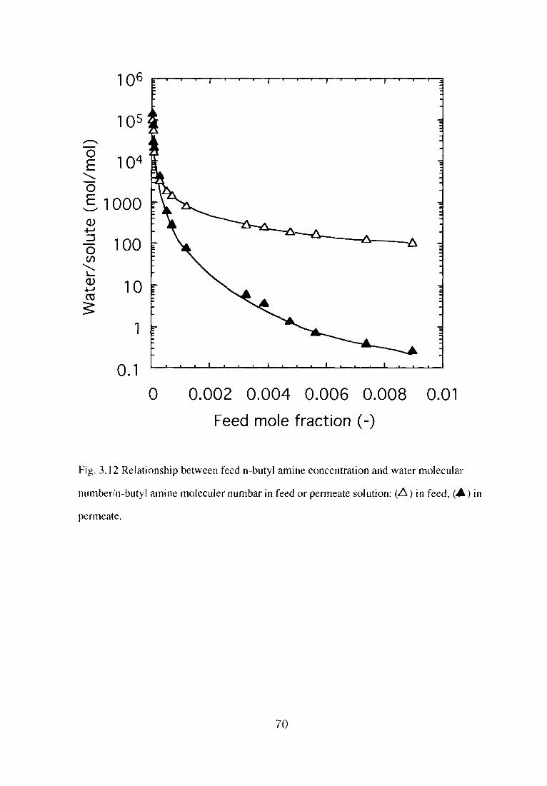
601
ら01
04
@00 ∞ 10
1 0 ー
コ
(}
潤クきo∈)920の\」Φ冨≧
1
910
0 0.002 0.004 0.006 0.008
Feed mole fraction(一)
O.Ol
Fig.3.12Relationship between feed nbutyl amine concentration and water molecu量ar
nuniber/n-butyI amine moleculer numbar in feed or permeate solution:(△)in feed,(▲)in
perlr匿eate.
70

0.005
4 つ」 ∩乙 1
0 0 0 0
0 0 0 0
コ ロ コ コ
り
(一
_ろ∈)⊆o焉」芒8⊂8[士○]
0
0
0.5
(一
_一
Z∈)⊂OPσ。」芒ΦOにOO[NエZ①工寸O]
4 つ」 ∩乙 1
0 0 0 0
0
0.002 0.004 0.006 0.008 0.01
Feed mole fraction(一)
Fig.3.13Relationship between feed n-butyl amine concelltratioTl and lOl l「concentratioll or
lC4HgNH2iconcentration.:(△)IOH-i,(▲){C4HgN H2 1.
71

0.Ol~0.02 feed mole fraction, the concentration of permeate solution was over O.01 mo且e
fraction and the degree of dissociation is iow. The acetic acid flux significantly increased
with increasing fbed concentration because the permeation of aceticacid was almost the same
as the tota畳acetic acid permeation. Over a O.025 feed mole fraction, the diffusivity of acetic
acid was also prevented by hydration. The tentative il里ustration of the permeation through the
PDMS membralle for solしlte-water mixture is shown in Fig.3」0」n the feed solution, water
inolecules are bulk water or hydrate water but when the solution is concentrated in the
membrane, bulk water is deceased and hydrate water is included、 hence, the diffusivity of
molecu)es isprevented・
The flux as a function ofthe feed n-butyl amine concentration is shown in Fig.3.11for
the n-butylamine acid solution. The water flux increased until a maximum at the feed n-
butylamille mo}e fraction of O.0015and then decreased with increasing feed concentration.
TIle mlmber of water molecules per one sohlte in the feed or permeate solution as a
functbn of the feed n-butyl amine concentration is shown in Fig.3.12. The water flux
increased until a maximum feed n-buty且amine mole fraction of O.0015 because the hydration
promoted water diffusion. However, at the high feed concentration, mole fraction>0.0015,
the l由utyl amine solution was concentrated in the PDMS membrane and the permeate
concentra〔ion was over O.05 mole fraction. The hydration numbers for various soh星tes are
showii in Tab】e 3.L The hydration number of water molecules on n-butyl amine is 20.
Almost all wεlter molecules are illvolved in hydration at the O,048 mo且e fraction. When the
concentrations are over O.048 mole fraction, the water molecules hydrate to severa且solute
molecules and the 1notion of the water molecules are prevented. Hence, it is considered that
over a O.0015feed mole fraction, the n-butyl amine solution was concentrated in the PDMS
membrane and the diffuslon of water molecuies was prevented。
The total flux increased until a maximum at the feed n-butyl amine mole fraction of
O.0015and then decreased with increasing feed collcentration due to the effect of water flux.
The 11-butyj amil】e伍lx was signiflcantly increased with increasing feed concentration.
For the permeation of an aqueous n-butyl amlne solution, n-butyl amine,11-butyI
72

ammomum lo11・and water molecules are penetrats. The degree of diss ociation as a function
of the feed n-butyl amine concentration is shown in Fig.3.8. Tlle hydroxy or n-butyl
ammonium ion as a function of the feed n-butyl amine coIlcell亡ration is showll in Fi93. B.
Below a n-buty量amine mole fraction of O.0015, the concentration of permeate solutio置】was
below a O・02 mole fraction・Hence, the degree of disiccation is high and the perlneatic)n(》f
the n-butyl ammonium ion affected the total n-butyl alnine permeation.
The solubility of the n-buty置ammonium ion is not very high alld the di ft’usi vi ty of
water, which is a smali moleculejs high. Therefore, the permselectivity of Ihe i}-butyl
ammonium ion is not very high. The enrichment factor of n-butyl amlne was low at a
O<0.0015feed mole fraction。 At a O.0015~0.008 feed mole fraction. the ll-butylamiIle flux
significantly increased with increasing feed concentration. When the n-bu1yl ainine mole
fraction was O.0015~0.008, the concentration of the permeate solUtioll was over O.02 molc
fraction. Hence, the degree of dissociation ls low and the permeati()11(,f n-butyl amine was
almost the same as the totai n-butyi amine permeation. Over a O.OO8 feed mde t-r;tctiol), lhc
diffusMty of l1-butyl amine was aiso prevented by hydratlon.
3.4Conclusions
in this chapter, the basic permeation behavior f()r PDMS membrane.【he hydratioII
effect on the sorption-diffusion mechanism f6r various organic compて)unds which js
important like physic and chemical properties of penetrates was investiga重ed.
The water molecule adjacent to the solute becomes less mobiie ill aqueous solL」tions of
organic compounds than in the pure water due to the hydration. The liquid waIer has a
distribution of hydrogen-bond clusters and space. The organic con)pounds disso】ve i1)lhe
space of the liquid water. The water molecules hydrate the solute molecules. The mo重ion of
the water molecules are prevented in the solute vicinity.
Tbe water flux lncreased until a maximum at a low feed solute concentratlon because
the hydration promoted water diffusion・However, at the high feed concentra110n, solute was
concentrated in the PDMS membrane and pemeate. Almost al)water molecules are
73

concerned with hydration when the concentration of(water molecules)/(solute molecules)is
the same as the hydration number. When the actuai concentration was over this
concentration, the water molecules hydrate to several solute molecules and the motion of the
water molecules is prevented, During pervaporation, the solute was concentrated in the
PDMS membrane and the diffusion of water molecules was prevented. The permeation of the
aqueous solution of dissociated solute included more interesting phenomena. For permeate
transport、 a solution-diffusion mechanism is important The permselectivity of ions is not
very high. Furthermore、 the diffusivity of water, which is a small molecule, is high. When
the dissociate solute mole fraction was a bw, the concentration of permeate solution was a
low mole fraction and the degree of dissociation is high. Hence, the permeation of organlc
ions affected the total dissociate soh董te permeation. The enrichment factor of dissociated
c(,mpotmds was low in the solution with a high degree of dissociation. At the high feed
concentration, the solutlon was concentrated in the membrane and the degree of dissociation
is low. The solute flux significantly increased with increasing feed concentration because the
permeation of solute itself became the tota且solute permeation, until hydration prevents
di ffu si on. The diffusivity of solute and water molecules are prevented by hydration when the
collcentration of(water molecuies)/(solute molecu且es)is the same as the hydration number.
It was suggested that the enhancement of solubility of PDMS membrane was important
Io minimize the effect of the selectivity decrease for djssociate penetrates.
3。5Ackllow且edgments
The authors are grateful to the Fuji Systems Corporation for providing the PDMS
membranes.
3.6References
DA.Geiger. F.H. St田inger, A. Rahman,ノ. Che〃1.1)んy∫.、70、4185(1979).
2)K.NakaBishi. K. Ikari, S. Okazaki, H. Touhara.ノ.Che〃L P/1ぎ∫.,80,1656(1984).
3)J.E. Desneyers, M. AreL G. Perron, C. Jobicoeur,ノ. P/7y∫. Chetn.,73,3346(1969).
74

4)H. Tanaka』. Touhara, K. Nakanishj. N. Watanabe,ノ.C/78〃1. Phvs..80,5170 G984).
5}R・A・Kuharski, P・J・Rossky。」「,・4〃1. C/le〃~.∫‘♪(・.,106,5786 G984),
6)F.Franks,ノ. C/le〃1.∫‘)(㌧F‘ir‘1,d‘~y 1,73,830(1977),
フ)N,Nishi, K. Yamamoto.ノ. A〃~, C/le〃~.∫θ(・.、109.7353(1987).
8)D下・Coker, R・E・M川er. R.O. Wattts、ノ.(’he’11, Plハw.,82.3554(1985).
9)0.Ya. Samoilov, D1∫c. Faradの’∫α・.、24、141(1957).
10)H.Uedaira. mizu no bunshi kougaku(mo)ecu)ar dynamics of water);ill Japan,
Kodansha co. Ltd..Tokyo.(1998).
lDR.B. Hermann、ノ. P乃y5. Chem.,76.2754(1972).
12)RB. Hermann、ノ. Phy.y. Che’η..79,163(1975).
13)H.S. Frank、 A.S.Quist,ノ. Che’η. Ph.ys.,34,604 G961).
14)A.H. Narten, M.D. Danford, H. A. Levy, Dis(・. F‘’rααρの㌦9θ(・.,43、97 d 967).
15)M.V. Chandak. Y,S. Lin, W. Ji、 RJ. Higgins,ノ.ルle〃’hr.5τ‘・~.,133,231d997),
16)Y.Sun,C. Lin. Y.Chell, C. Wu,ノ, Me〃zhr.3(・~.,134、口7d997).
17)H.Takaba, R. Koshita, K, Mizukami, Y. Oumi,N. lt(,, M. Kubo, A. Fahmi,A.
Miyamoto.ノ.ルtembr. Sci., B4,127(}997).
i8)W.W.Y. Lau, J. Finlayson, J. M. Dickson、J. Jiang, MA Brook,ノ. Me〃か.∫でゴ.,
134,209(1997),
19)J,M. Watson. M.G, Baron,ノ.ルfemhr. Sci.,110,47(1996).
20)C.Dotremont、 B. Brabants, K. Geeroms, J. Mewis, C。 Vandecasteele、ノ.Me,nl)r. S{・i,.
104,109(1995).
21)S.Goethaert, C. Dotremont, M. Kui.iPers, M. Michels. C. Vandecasteele.ノ.ルfe’ηわr.
∫‘ゴ.,78,135(1993)、
22)S.Mishlma, T. Nakagawa,ノ. A〃!. iPθ4vm. Sc~.,73」835(1999)。
23)S.Mishima, T. Nakagawa,ノ. A〃’. Poly’71.∫(・ム,71,273(1999).
75

Chapter 4. Characterization of UV Modified PDMS Membranes with
Fluoroalkyl Methacrylate and Alkyl Methacrylate and their PermselectMty
for Chlorinated Hvdrocarbons
4.llntroduction
Ground water contaminated with chforinated hydrocarbons(VOC-Ci)such as
trich且oroethylene(TCE)and tetrachloroethylene(PCE)which are used widely in detergents
fbr meta且sand cleaning, etc., has been a social problem. Their toxicity has been made clear
f()rseveral years i,Recently,the effluent isregulated, theirdischarge is regulated and the use
of s ubg. titutes are considered. The purification of contaminated water has been extensively
studied2。 Pervaporatlon is an attractive and alternative to traditional methods(e.g, aeration,
adsorption(,n activated carbon, phαolysisand ozonization)for removing Jow concentrations
of organic solvents from waste water because of its energy saving features and has been
studied:43. ln the removal of very low concentrations of VOCCI from these contaminated
waters(<10009/m3), the use of pervaporation applications with membranes that permeate
VOC-CI preferentially has been considered3. The high selectivity of pervaporatlon makes it
potentially very interesting for continuous recovery of VOC-C且under compatibie conditions4-
9.
Pervaporationρerf()rmance of a membrane is determined by both the sorption and the
dit’fu g. ion characteristics of the permeating components ln the membrane.
Polydimethylsiloxane(PDMS)has been we[1-known as an exceHent polymer
lllembrane materiHl because of its high permeability(diffusMty)to gases and liquids.
Fluorinated polymers have also been studied as membranes for organic aqueous mixture
separation翫pplicatioll and are expected to have excellent affi nity for the organic compounds
due to their hydrophobicity based on the low surface energy9-12。 The enhancement of the
affinity of PDMS for chlorinated hydrocarbons using fluoroalkyl methacrylates(FALMA)is
interesting. For this lmprovement. the blending of PDMS and poly(FALMA)is difficult due
to the Iow af伽lty of PDMS f6r poly(FALMA).
76

ln this chapter, as the tl rst step of improvement. the PDMS membrane was mc)dified
using sorbing fluorlnated alkyl methacrylates fbllowed by UV irradiation in order to maln面n
high diffusivity and increase the chlorinated hydrocarbon partition coet「ficieIlt illto the
membrane. The effects of the刊uoroalkyl side chain on increasing the chlorina重ed
hydrocarbon partition coefficient into the membrane were determilled witll f1㈹rinated 11-alkyl
meth,acrylate(FALMA)and noコ浦uorlnated闇lkyhnethac1)・late{ALMA),
4.2Experimental
4.2.lMaterials
Commercial PDMS membranes(Fuji Systems Corporatioの,70μm thiek、 wel’e【3sed
throughout thls work.22,3,3,3-pentafluoropropyi methacryla【e(PFPMA).22,3,44,4-
hexafluorobutyl methacrylate(HFBMA),2-(perfluorobutyl)ethyl methacrylate(PFBEMA),
旧,IH,9H-hexadeca伽orononyl methacrylate (HDFNMA) (Daikitt };ifle (’hemicEl}
Laboratory Corporation), butyl methacrylate(BMA)alld hexyl me1hacrylate d{MA)(SpeciこLl
grade、Tokyo Kasei Kogyo、 Ltd.)were distilled and used, TCE. PCE. t J.t “i’ichk、roethane
and 2-propanol(Special grade,Waco Pure Chemical Industries, Ltd.)were used as received.
The physic chemical properties of FALMA and ALMA used inthis study are shown ill Table
4.1.
4.2.∠The modi∬cation of PDMS Membrane by UV irrdiation
APDMS membrane(d=7cm)was soaked in methacrylate mon〈)mers at rQom
temperature. After reaching an equilibrium, the membralle was taken out of the monomer
and excess sQlutlon on the surfaces was wiped off wlth filter paper. The membrane was then
irradiated with a high pressure mercury lamp(400W・ 365nm)on only one side of the
membrane at a distance of lO cm. After the irradiation, the membrane was placed between
filter papers and dried for more than 48 hours in a vacuum oven.
4.2.3Characterization of the modlOed PDMS membrane
77

X-ray photoelectron spectroscopy(XPS)spectra were obtained using an IPS-9000SX
(JEOL. Ltd,)with MgKαexciting radiation(1253.6eV).The X-ray gun was operated at
lOe V with a sample chamber vacuum o臼ess than sx 10’9 Torr. The XPS spectra were
recorded at two electron emission angles(J)of30°and 90°.
Table 4. 1 Structure of various FALMA&ALMA used in this study
Cく)m ound Abbrc、ria!ion Formuja b,
22.3.3,3-Pen皇aflu{}roproP}I
mcthacr、 late
2.2.3A、4.↓Hc\aflし!orobut>’1
1nc1hacr、 lu【c
2-(Pcr[1u{,「〔}but>Dc璽h>1
「nelhacr、1と盈le
lHj旺9H-Hc、adじcalluorenon、l
inc【hacr、.1こ匹己c
Bしtt、Imclhacハlalc
トlc\、1眺1clhaCl、 Iatc
FALMA
PFPMA
Hb’BMA
PFBEMA
田)FNMA
ALMA
BMA
HMA
CH 2=C(CH 3)COO-
CH 2 CF 2 CF 3
CH 2=C(CH 3)COO-
CH 2 CF 2 CHFCF 3
CH 2=C(CH 3)COO-
CH 2 CH 2(CF 2)3CF 3
CH 2=C(CH 3)COO-
CH 2(CF 2)8H
CH 2=C(CH 3)COO-
(CH 2)3CH 3
CH 2=C(CH 3)COO-
(CH 2)5CH 3
55°C/100mmHg
74℃/100mmHg L
61℃/5mmHg
II2℃/7mmHg
164℃
70℃/5mmH
The IR and ATR-1R spectra were obtained using I800 FT-IR/ATR spectroscopy
(Perkin-Elmer Co., L{d.).The instrument was operated at cycle=30.
The liquid film method was used in IR measurement For ATR, the KRS-5(T量Br-
T(ll))internal refraction element(IRE)was used at an incident angle of45°.
The dif陀renti挽i scanning calori meter(DSC)curve was obtained uslng a DSC7(Perkin-
E且mer Co.. Ltd.). The DSC scan started from-150℃and was measured up to 300℃, The
rate of temperature increase was usually IO℃/min.
4.2.4Pervaporation exPe「iment
The pervaporatioll experiments were perfbrmed using the continuous-feed type at
78

25℃・Thq・pP・・at・・is sh・w・i・Fig・4」・Th・feed・・1・ti・・wa・ci・c・1・t・d th…gh the cel1
・・d the feed t・・k・Th・m・dl制・曲…f重h・memb・ane w・・k・p由c・・tact with th・feed
solution in the celL The effective membrane area in the cell w翁s l9.6 cm2. The pressure on
the permeation side was kept below lOTorr by vacuum pulnps. Upoll reaching steady state
flow conditions・the permeate was cohected in traps cooled by Iiquid llitl・ogel1(・196℃)a1
timed interva且sjsolated from the vacuum systeln. alld weighed. The permeatioll r託lte.
flux(J), was obtained using eq.(4.り
J=Q/At (4.1)
where Q is the amount that permeated during the experimel)tal time interval, t. and A is the
effective surface area. The VOC and water伍1x were calculated frol1⊃豊be t(.}tal flux aikhhe
permeate c・mp・sltlon・The concentration・f TCE in the feed and pem】eate s・M・n was
determined by gas chromatography wl亡h an FID detector(Sitnazu GC-14A), The gas
chromatography was operated using a Cromosorb W 60-80 mesll colunii⊃wl1h Silicone DC-
200、20wt%liquid phase. The VOC concentration ill the permeate was high. which is far
beyond its solubility limit ill water. The phase separaIion重ook place in the permeate.2-
propanol was added to the permeate solution. The permeate soiution was homogenized al1(l
analyzed to determine the VOC concentration. The separation factor during per>aporatiol1,
αpv・was calculated as
αpvニ{Y(レX)}/{(レY)X} (4.2)
where X and Y denote the concentrations of VOC in the feed alld permeate solutions、
respective且y.
4.2.5Sorption measu「ement
The dried and weighed membrane was immersed in TCE solution and sealed at 25℃until
equilibrium was reached. The membrane was then taken out of the vessel, wiped quickly
with flter paper and weighed. The concentration of TCE solution soaked in the membrane
was determlned using the apparatus in the schematic diagram shown in Fig.4.2. The
membrane on reaching equillbrium was taken out of the vessel. wiped qulckly with filter
79

]
7
σ O
8
3
1
o Q 0 4
}5
6
○
9
」11
1:magnetiC Stirrer
2:pervaporation cell
3:cQnstant temperature bath
4:greaseless cocks
5:ground giass joints
6:cold traps for collecting sample
0
7:vacuum gauge
8:cold trap
9:vacuum pump
10:micro tube pump
11:feed solution
Fig.4.1Pervaporation aPPa「atus・
80

P・p・・and placed i・t・ap A・Th・t・ap w・・c・・nect・d t・the・pP・・at・・a・d q・i・kiy…1・d by
liquid nitrogen・After the apParatus was sufficientty evacuated, cock B was closed and the
TCE solutlon soaked in the membralle and vaporized by heatlllg wlth a drier was collected ln
cooled traps. The concentration of TCE solution ill the feed and the soaked membr託me was
determined by gas chromatography,
Vacuum ↑
A
○
A:cold trap for membrane
B:valve
C:cold trap for collecting samples
Fig、42 Apparatus for the composition measurement inthe membrane.
81

4.3Results and discussion
4.3.1Characterization of the modlfied PDMS membranes
The time that the membrane was soaked into the monomers was determined from the
determination of equilibrium swelHng time by weighing the membranes。 Dependence of the
degree of sorption on immersion time is shown in Fig。4.3 for HFBMA, HDFNMA and
BMA.The degree c)f sorption was increased with increasing immersion time and equilibrium
was reached il日hour. The immersion time was determined to be l hour.
The separation factor was calculated from the pervaporation measurement for each
membralle f(,r which the UV-irradiation time was varied by 3,5、10, i5,20, and 30
minutes、 Depelldence of the selectivity in pervaporation on reaction time(i.e.、 irradiation
time)is shown in Fig.4.4。 The selectivity was increased with increasing reaction time and
equilibrium in l5mjnutes. The reaction time was determined to be l5minutes. In this study,
the PDMS membranes were immersed in FALMA or ALMA for l hour and irradiated by UV
for I 5 minutes to modlfy them, The modified PDMS membranes were then characterized and
ultilized in pervaporation.
The polymerization of FALMA and ALMA by UV irradiation was investigated.
HFBMA, HDFNMA and BMA were filled in a flat-bottom dish to a height of lcm and
il’radiated for ls minutes and 2 hours. The FALMA and ALMA irradiated for 15 minutes
were highly viscous. The FALMA and ALMA irradiated for 2 hours were hardened. The
FALMA and ALMA irradiated for 15mlnutes were measured by Infra red(IR)spectra using
the liquid film method. The FALMA and ALMA irradiated for 2 hours were measured by
ATR. The results are shown in Fig,45.
The IR spectra showed a decreasing olefin C=C peak at 1655±5 cm国lfor the l5-min
irradiated FALMA, but the peak was not found fbr 2-hour irradlated FALMA. Therefore,
the sorbed FALMA and ALMA could be polymerized in the PDMS membranes,
The surface morphoiogies of the modified membranes were analyzed by ATR. The ATR
spectra for the modified PDMS membranes was almost the same as the unmodified PDMS
membrane, The FALMA poly rner in PDMS was around iwt%. Because these was
82

20
「V ∩) 5
コ
(ま剃≧ノ)⊂08」oεoΦΦ」OΦO
00 20 40 60 80
Sorption time(min)
120
(承峯)⊂08」oεoΦΦ」0ΦO
∞ 80 60 40
1
20
1000
Fig.4.3 Degree of sorption of methacryrates throughPDMS membrane.:(口)HFBMA、(△)
HDFNMA,(O)BMA.
83

(-)」oぢ3⊂ε9巴Φ゜り
1200
1000
800
600
400
200
00 5 10 15 20 25 30
Reaction time(min)
Fig.4.4 Ef’fect of UV irradiatめn time on separationfactor of TCE-water mixture through
modified PDMS membrane.:(□)0.Olwt%feed solution for HFBMA-modified-PDMS
membrane、(△)0.025wt%feed soltition for HFBMA-modified-PDMS membrane,(○)
0.Olwt%feed so且ution for HDFNMA-modified-PDMS membrane,(◇)0。025wt%feed
solutk)n for HDFNMA-modified-PDMS membrane.
84

4000 3000 2000 1600 1200 800 Wave cut number(cm-1)
樋4.5・IR、p・c・…fHFBMA・・d UV irradi・…IHFBMA・
85
400

一140 -100 -60 -20
Fig.4.6 DSC curve(,f l)DMS.
Temp(°C)
’llld HFBMA-niodified-PDMS and UV irradiated HFBMA.
86

且ittle FALMA polymer in the PDMS membralle、 the peak for the polymer was Ilot c)btained
by low sensitivity ATRI3.
The DSC…ves・f the m・d酒ed membraηe・a・e・sh・wll l・Fig.4.6. Th・gla∬t・・nlSiti・・
peak at-124℃and a bond energy peak at-100°C were observed for PDMS. The peak for
the homopolymer of FALMA polymerized by 2-hour irradiation was llot observed ill the
range of.150°~300℃. The polymer polymerized by UV irradiation has a wide range of
polymerization degrees, therefore、 these peaks were not obtained. For the membrane after
modification by FALMA, the endothermic peaks were not observed. The sorbed FALMA
and ALMA were consldered to be polymerized in the PDMS membranes.
The surface morphologies of the modified membranes were analyzed by XPS spectra.
The ratios offluorine、 oxygen、 carbon. and silicon atoins were analyzed and calculated fbr a
few nm beneath the surface on the grafted membralle at 30°and 90° 垂?盾狽盾?撃?モ狽窒盾氏@elllissiOll
angles and are characterized in Table 4.2。 In this spectra. the compositioll of atoms are
determined up to 4.5 and gnm depth from the surface at photoelectron emission angles(》f 30q
and 90q, respectiveiyl3. As the length of the fluorlnated side chain of fl UOI’()alky】
methacrylates increased(i.e., number of fluorine atoms increased), the ratio of tlu(》rille
atoms was increased at the surface. The ratio of fluorlne a重oms at 10°was higher thall that a吐
90°;moreover, the resuks of the UV-irradiated side and non UV-irradiated side were almost
the same. ln this study, the PDMS membranes were immersed in FALMA or ALMA and
irradiated by UV. These composite results suggest that the reaction of the sorbed monomer
by UV-irradiation started with the irradiated surface and continued into the membra ne i 3. it is
considered thaUhe degree of reaction on the lnside and the reverse side()f出e PDMS
membranes was且ower than that on the surface.
The FALMA polymer in the modified PDMS membrane was extracted using acetone.
The surface morphologies of the extracted membranes were then ana∬yzed by XPS spectra,
The ratio of fluorine atoms on the extracted membrane were decreased to 60-709を, of theしm-
extracted membranes. It isconsidered that the polymerized FALMA and ALMA in PDMS did
87

Table 4.2 Fluorine to silicon atomic ratio for surface of PDMS and modified PDMS
membranes by XPSAnalysis“
modified membranes Electron
emlSSIon
anoie
Atomic ratio CH 2=C(CH 3)COOR
FISi -R
angle
PFPMA-modified-PDMS
(modified face)
10°
90°
O.OI77
00138一CH2CF2CF3
HFBMA-modified-PDMS IO° O.0445 -CH2CF2CHFCF3(modified face) 90°
o(reverse side) 90
0.0086
0.0171
PFBEMA-modifted-PDMS(tnodified face)
10e
90°
0.0726
0.0210
一CH2CH2(CF2)3CF
HDFNMA-mod甫ed-PDMS 10° 0.24i -CH2(CF2)8H(modified face) 90° 0.173
o(reverse side) 10 0.豆27
a FISi:Fluorine atomic ratio(%)/Silicon atomic ratio(%).
not have a sufficielltly high degree of polymerization to be extracted. The extraction of the
FALMA polymer in the modified PDMS membrane was investigated with O. lw%aqueous
TCE soJution, The ratjo of fluorine atoms on山e jmmersed membrane was not decreased.
The polyrnerized FALMA and ALMA in PDMS were not extracted by O.亘w%aqueous TCE
S(》lution.
4,12The ef¥℃cts of the fl uoroai kyi side chain on Sorption and pervaporation
The degree of sorption and the composition of TCE sorbed into the membrane are
shown inTable 43. The degree of sorption was Iess than l wt%using the O.035 wt%TCE
sohltion. and the TCE conce耐ration in the sorbed solutjon could not be measured. The
degree ()f sorptk川in the modified PDMS membrane and the PDMS membrane was且ess than
10wt%for the O. I wt~佑TCE solution. Because the PDMS membrane used in this study was
crosslinked and there wag. little FALMA polymer in the modified PDMS membrane、 the
88

Table 4.3 Sorption selectivity for PDMS alld modified PDMS membralles
1>Iembrane
TCE in Degree of
feed Swelling
(wt%) (wt%)
TCE ill Separatkm
nlenlbrane
(wtりの faclorα、
PFPMA-modified-PDMS
HFBMA-modified-PDMS
PFBEMA-modified-PDMS
HDFNMA-modified-PDMS
BMA-modified-PDMS
HMA-modified-PDMS
UV-modified-PDMS
PDMS
0.034
0.10
0.035
0.10
0.038
0.10
0.037
0.11
0,035
0.11
0.038
0.10
0.035
0.10
0,040
0。ll
<ぬくη<∬<靭く認くΩ〈禰く駕
ηあゑ蕊ぬ露あ函
り ラ エ ラ ラ ラ ナ
ラ
く
く
く
く
く
く
く く
、・45、一98.一96、・罰、・嘱.・鱒.一糾、一42
a:Not detected.
degree of sorptbn was slight. The TCE concentration of the s()rbed solution in the modificd
PDMS membrane was between 32 and 66 wt%for the O」wt91c. TCE solution, and the
separation factor during sorption,αs, was 400-1800」n FALMA monomers, HDFNMA-
modified-PDMS had the highest TCE so且ubikity. The sorbed TCE increas ed with increasing
length of the fl uorinated side chain of FALMA, Le., the m1mber of tl uori ne atolns. Both
modified membranes with non.fluorinated ALMA and only UV-irradiated PDMS membrane
were affected much less compared to the membranes modjfied wlth FALMA. The solubility
of the mod而ed PDMS membrane was attributed to the length of the伽orinated side chain of
FALMA.
89

Table 44 Permeation selectivity for TCE-water mixture through PDMS and modified
PDMS membranes
Membrane
Composition(wt%)
Feed Permeate
Flux Separation
(IO=ikg/mヲh) factorα
PFPMA-modified-PDMS
f{FBMA-modified-PDMS
PFBEMA-modified-PDMS
HDFNMA-modified-PDMS
BMA-modified-PDMS
HMA-modified-PDMS
UV-m〔》dified-PDMS
PDMS
0,010
0.027
0.0{2
0.026
0.Ol3
0.027
0.011
0.024
0.OI1
0.024
0,011
0.025
0.009
0,024
0.Oll
O.028
478 3 40299 46
285680-836254338
ー 「∠-量
1
94409338999-2775
235769-932225633
The pevaporation resttlts of the dilute TCE solution through the modified PDMS
membranes are shown ill Table 4.4、 The sejectivity increased with increasing且ength of the
fiuorinated side chain of FALMA, i.e., the number of fluorine atoms. In FALMA
mollomers, HDFN MA-modified-PDMS had highest selectivity. Both modified membranes
with non一翫orinated ALMA and only UV-irradiated PDMS membrane were affected much
且ess compared to the membranes modMed with FALMA。 In the modified PDMS、 the best
separation performance was shown、 due to the introduction of the hydrophobic polymer、
poly(FALMA).
The relationship between the separation factor in permeation(αp、.), the separation
factor iII sorptiol1 (αs), and the apParent separation factor in diffusion (αd) is given by
90

Eq.(4.3).
αP、ニαs・αd (4・3)
(PA/PB)=(KAIKB).(DAA)B) (4.4)
where PA and PB denote the permeation coef行cients of compollents A and B. Kへalld KB
denote the solubility coefficients of cQmponents A and B and the diffusion coefficientg. of A
and B、 respectively・The solub川ty coef罰cient lsglven as
Ki=Cm/Cs (45)
where Cm and Cs denote the concentration of component i in the membralle and the solution.
respectively. Because the mo】ecular volume of TCB is larger thIm that()f water. the
diffusivity ofTCE is less than that of water. The solubihty of TCE then signit’icantly affects
the permselectivity」n this study,the membrane that showed the best separation perlbrmance
was the membrane having the highest TCE concentration in the sorbed solution.
The伽x of the modified PDMS membranes was increased or rejatively the sllme
compared to that of a non-modified PDMS membrane. This could be dロe to the factthat little
reaction of the FALMA and ALMA occurred in the membrane and the diffusivity was as high
as that of the non-modified PDMS membrane.
L
Table 45 Pervaporation data for chlorinated hydrocarbolls-water mixture through PDMS
and modified PDMS membranes
(”hlorinated h‘drocarbr)n Mcmbranc
(Jomposition(N、 t‘1‘}
恥£d Pcrmcatc
Hux Scpamtkm〔1‘)㌦Ωノmヲh) i’uctc〕rα,
Tctrachloroethンlene
1,1.1-trichlorocthane
HDFNMA-modilled-PDMS
PI)MS
Hj)FNMA-
moKlified-PDMS
PDMS
O,0(}6i
O.OO65
0,‘)‘》94
0.0088
3,7
1.3
5.5
2.4
58 8-
32 33
64{}
2{X〕
620
280
The pevaporatlon results of dilu霊e VOC solutions through the HDFNMA-modified
91

PDMS membrane and the PDMS membrane are shown in Table 4。5. The selectivity of the
HDFNMA-modified-PDMS membrane was high compared to that of the PDMS membrane.
The flux of the modified membrane was not much affected by modification.
4.33The e仔ects of the fluoroalkyl methacrylate on diffuslon
The permeate TCE concentration as a function of the feed TCE concentration is shown
in Fig.4.7 for the modi負ed PDMS membranes。 For all the membranes、 The TCE
collcentration in the permeate increased with increasing feed collcentration. For the FALMA-
modified-PDMS membranes, a high permeate TCE concentration was obtained.
The TCEflux as a function ofthe feed TCE concentration is shown in Fig.4.8 for the
modified PDMS membmnes. For all the membranes, The TCE concentration ln the permeate
were increased with increaslng feed concentration, and for the FALMA-modified-PDMS
membranes、 the tendency was Significant.
hl pervaporation through the modified PDMS membrane, a,ltrade off”of permeability
and selectivity was not obtained・
The flux as a function of the feed TCE concentration is shown in Fig.49 for the
modified PDMS membranes. The flux of the modified PDMS membranes was increased or
relatively the same compared to that of the non-modified PDMS membrane. For the FALMA-
modified-PDMS membrane, the伽x decreased with the feed concentration. The月ux
increased with increasing feed concentration in pervaporation through the ALMA-modified-
PDMS membralle.
The fltlx as a function of the feed concentration in pervaporation through a non-porous
homogeneous membrane is k聖10wn as Fick’s fi rst law and is given by Eq.(4,6).
Ji=-Di(δC/δx)i (4.6)
where Di.Cand x denote the diffusion coefficient of component i, the concentration and the
membrane thickness. respectively. Fick’s first law pertains to any part of the membrane.
With increasing feed concentration. the concelltration in the membrane increases and the TCE
92

25
0 5 0 5
うこ
(ま妄)Φ罵Φ∈」①α三山りト
00 0.01 0.02 0.03
TCE in feed(wt%)
0.04
Fig.4.7 Pervaporation of TCE-water mixtures throughPDMS and modified PDMS
membranes.:(□)HFBMA-modified-PDMS membrane,(◇)HDFNMA--moditled-PDMS
membrane、(○)BMA-modified-PDMS membrane,(△)PDMS membrane.
93

(f∈\9)×⊇畠oト
O.008
0.007
0.006
0.005
0.004
0.003
0.002
0.001
00 0.Ol O.02 0.03
TCE in feed(wto/o)
0.04
Fig.4.8 Eft’ect of feed concentration on TCE刊ux for TCE-water mixture in pervaporation
through PDMS and modified PDMS membranes,:(口)HFBMA-modified-PDMS
membrane,(◇)HDFNMA-modified-PDMS membrane,(0)BMA-modified-PDMS
membrane、(△)PDMS membrane.
94

(f∈\9×コ江
0.05
0.04
0.03
0.02
0.Ol
00 0.01 0.02 0.03 0.04
TCE in feed(wt%)
Fig.4.9 Effect of feed concentration on f】ux for TCE-water mlxture in pervaporation throvgh
PDMSand mod笛ed PDMS membranes.:([1)HFBMA-modified-PDMS membrane,(◇)
HDFNMA-modified-PDMS membrane,(○)BMA-modified-PDMS membralle,(△)PDMS
Inembrane.
95
伽xincreases. However, the flux decreased with the feed concentration for the FALMA-
modified-PDMS membrane. Due to the introduction of a hydrophobic polymer. FALMA, the
TCE quantity sorbed into the membrane was so high that the diffusion of water was
prevented7・i4;in turn, the flux decreased。
4.4Conclusions
Membrane materials that preferentially permeate ch畳orinated hydrocarbons in
pervaporation were investigated. The PDMS membrane in which FALMA and ALMA were
sorbed, was irradiated by UV and ultilized in pervaporation. The polymerized FALMA and
ALMA were contained ina modified membrane. The sorbed TCE ill the modified membrane
increased with illcre盈sing length ofthe伽orinated side chain of FALMA, i.e., the number of
fluorine atoms. The membrane that showed the best separation performance was the
membrane having the highest TCE concentration in the sorbed sdution, The flux of the
modified membrane was not much affected by modification. The resu]ts of pervaporation and
sorption experimenIs showed that the partition coef箭cients for chlorinated hydrocarbons
increased with the increase ill n-fluoroalkyl chain Iength of the n-fluoroa[kyl methacrylates.
alld, in turn. the permselectivity increased. ln the permeation of the modified PDMS
membrane, due to重he introductlon of a hydrophobic polymer, FALMA, the TCE quantity
sorbed illto the membrane was so high that the diffusion of water was prevented、 in turn, the
flux decreased.
45Acknowledgments
The authors are grateful to Fuji Systems
nlenlbranes.
Corporation for providing the PDMS
4.6Reference
DThe Environment Agellcy,Japan
Maruzen Ltd.、Tokyo G 988).
、 Chemical compounds in environment; in Japan.
96

2)M・M・t・utani・R・g・且・ti・n and t・e・tment・f・nvi・・nment・1 w・t・・a・d w・・t・w・t・・二i・J・pan.
IPC Ltd..Tokyo(i994).
3)S.Yamahara, S. Nakao,ル1‘iku (’ne〃ihrane),18,69(1993).
4)T.Nakagawa、 A. Kanemasa, Sen’i Gakk’aishi、51,123(1995).
5)C・Dotremont, B・Brabants, K・Geeroms,』。Mewis, CVandecastee量e.ノ.Me〃~わr.∫(・~., I O4、
io9(1995).
6)PJ. Hickey, CH. Gooding,/.ル1e’nbr. Sci.、97、53(1994).
7)S.Goethaert, C Dotremont, M. Kuijpers, M. Michels, C. Vandecasteele.、ノ, A4e’〃hr.
S(ゴ.,78、135(1993).
8)M.Hoshi, T, Saito, A. Higuti,T. Nakagawa, Sen’i Gakka’.vhi、47,644(199 D.
9)K.Ogasawara, T. Masuoka, T. Iwatsubo, K. Mizogichi, Grθ‘〃1(ノwα〃er、37.47(1995).
10)T.Nakagawa,ルlak〃(nηe〃zbrane),20,156(1995).
lI)A. Negishi,Chemical of fluorine:inJapan, Maruzen Ltd.,Tokyo(1988).
12)M.Nakamura, S.Samejima, T. Kawasaki、ノ. Memhr.∫(・1.,36.343 d 988).
13)The society of Polymer Science, Japan, Shin koubunshi Jikkengaku(experimenta[
method in polymer science vol.10;in Japan, Kyoritsu press Ltd. d 995).
14)The society of Polymer Science, Japan, Koubunsi tho mizu(Poiymer alld Water);in
Japan, Kyoritsu press Ltd,(1995).
97

Chapter 5. Characterization of Graft Polymerization wi山F墨uoroalkyl
Methacrylate and Alkyl Methacrylate onto PDMS Membranes by EJectron
Beam and their Permselectivity for Chlorinated Hydrocarbons
5.1Introduction
Recent)y, the contamination of ground water and soil by volatile organic compounds
(VOCs)has become a social problemL2. Pervaporation is attractive and potentially cost-
competitive compared to these methods. The pervaporation of VOCs/water solution using
organophilic polymers has been studied卜24,
Polydjmethylsiloxane(PDMS)membrane has been the most widely used and studied
material to perform VOCs extraction because of its high permeability, ease of preparation into
several shapes and relatively slight thicknessio・i125』27. To obtain the more useful membrane
keeping the properties of the PDMS membrane、 the synthesis of copolymers of PDMS and
their impr{}vement by the incorporation of fiHers such as silicates and zeohtes have been
expected and studied l 5・i9. Fluorinated polymers are recognized as the practicai membrane
materials just like PDMS and have been studied as organic compounds by their
hydrophobicity based on tow surface energy 18・28’30. it is interesting to synthesize a more
useful membrane material by combining the PDMS and刊uorinated polymer. But, the affinity
of PDMS to fluorinated poiymer is low. Graft potymerization is a useful method to combine
the polymeric materia且s with incompatible chemical and physical properties. Graft
polymeriza¢ion call be achieved by ionizing radiation, gamma ray, electron beam, ultraviolet
light and plasma irradiation、 and several papers have bee童1 reported on graftil1931-60. In
chapter 4、 the PDMS membranes were modified by sorbing fluoroalkylmethacrylates
(FALMA)alld alkylmethacrylates(ALMA)using UV irradiation in order to increase the
pallttlotl coe伍clent(,f chlorinated hydrocarbons into the membrane. However, in this
method・the increase in the membrane weight by poly(FALMA)and poly(ALMA)is about
lwt%εled…beam h・・high ene・gy and i・abl・t・・ffe・tively g・aft-P・lym・・ize i・
qua・tity31.32.38.39・47・48-S 1。 Th・g・・wth・f th・g・aft・h・1・by p・lym・・izati・・st・rt・d with
98

reactive radicalscaused in the membrane 3 L32. Genera11y, vinyl monomer has been used in
graft polymerization, Preirradiation and simultaneous irradiatio蓬1 have been known as the
method of radiation-induced graft polymerization3 L32. Preirradiation is a method in which a
monomer is reacted with a polymer which had been irladiated ill advallce4L4ユ. In
simultaneous irradiation, monomer and polymer are irradiated simultaneouslジL3ユ. In this
study, the improvement PDMS membranes by graft-polymerizatk,n of FALMA to eiihaiice
the affinity of PDMS to VOCs was studied 3’5・7,The grafted membralles illcreased the
selectivity for VOCs and showed effecti、’e separation performance.
The solub川ty and diffusibi]ity of the monomer for the membrane are impollallt f()r the
preirradiation method. The solubi且ity is affected by the chemical affinity of the mon()mer fot’
the membrane. Also, the molecular volume is cbsely concemed with the dit’t’usibility of
organic compounds, Hence, for the preirradiation method、 the solubility parま】meter、 thc
octano1-water partition coefficient(Pow)and the molecular volume are impollallt. The
solubility parameter(δ)by Hansen61can be described as:
δ2=δ8+δP2+δh2 (5・1)
δ、F(△E(ノV)1/2 (5,1-a)
δp=(△Ep/V)1/2 (5」-b)
δh=(△Ehハ〆)i/2 (5.1-c)
whereδd,δp andδh represent the solubility parameter of dispersion, polarization al1(i
hydrogen bonding, and△Ed〆V,△Ep/V and△Eh/V represent the energy density of dispersiol1.
polarization and hydrogen bonding, respectively。 Total heat of mixing of sdvellt and
polymer(△Hm)isdescribed using the solub川ty parameter as follows6i:
△Hm=Vm・(δsolvenじδPol}・mc・)2・φs・)lvcnピφP〔)1>mcr (5.2)
where Vm andφrepresent the total molecular volume of the polymer solution and the volt層me
fraction in the polymer so】ution, respectively. When△Hm is Iower, tha重is, the differellce of
δsolvcnI andδpolymcr is smaller, sdvent and polymer are mixed more homogeneous韮y. The
hydrophobicity is used to indicate the physical property of the molecule which go>erns its
partitioning into the nonaqueous partner of an immiscible or partially immiscible solvent
99

pair62。 According to Nernst62、 the partition coet’ficient can be simply descri bed as:
P=C〔》/Cw or logP=10gCo-logCw (5.3)
where Co and C、、 represent molar concentrations of the partitioned compound in the organic
and aqueous phase, respective量y・The octano1-water partition coef顎cient(Pow)has been
generally used in expressing hydrophobicity62・63. ln hydrophobicity, Pow is c且osely
concerned with the solubility of organic compounds62・63.
In thischapter, we grafted PDMS membranes with FALMA and ALMA by the electron
beam preirradiation method. We then investigated the effect of solubility and diffusibility of
the mollomer on graft polymerization and applied the grafted membrane to pervaporation,
5.2Experimentaj
5.2.I Graft polymerization of fl uoroalkyl methacry置ate by electron beam
Commercial PDMS membranes(Fuj i Systems Corporation),50μm thick, were used
throughout this work.22,3,3,3-penta伽oropropyl methacrylate(PFPMA)、2,2,3,4,4,4-
hexa伽orobutyl methacrylate(HFBMA),2-(per伽orobutyl)ethyl methacrylate(PFBEMA),
1H,1H,9H-hexadeca伽orononyl methacrylate (HDFNMA) (Daikin Fille Chemical
Laboratory Corpor飢ion), btityl me重hacrylate(BMA)and hexyl methacrylate(HMA)(Special
grade,T()kyo Kasei Kogyo、 Ltd.)were used as received to avoid homopolymerization,
Trichloroethylelle(TCE),2-propanol and acetone(Special grade,Waco Pure ChemicaI
llldustries, Ltd.)were used as received. The abbreviation and physico-chemical properties of
FALMA and ALMA used inthls study are given inTable 5.1,
The graft polymerization was performed as reported by Ishigaki et aL47・48. The schematic
diagram of the apparatus is shown in Fig.5.1
Preirradiation:
APDMS membrane of 7x7 cm evacuated in advance was placed in a polyethylene bag
under nitrogen・The bag was then placed on dry ice and irradiated by an electron beam of a
100

total dose of l50 kGy, The membranes were then placed ill contact with degassed FALMA
or ALMA monomer in the hquid phase under vaccum. After the polymerization was ended,
the membranes were rinsed in acetone overnight to remove the homopolymers and the
nonreacted monomers and dried for 48 hours i!1 an evacuated vesse1.
Table 5.l Composition and properties of various FALMA and ALMA used inthis study
(’OM ound Abbre、・iation トL)rlnula MW bD,
22.3,3.3-Pentafiu〔}ropropyi
mcthacハ11ate
223.4.4.4-Hcxaflu()r〔〕but、1
ピmethacrylate
2-(Pclずluorobut)’bcthyl
mcthacハ1a〔C
IH.IHgH-Hcxadecafluorononyl}了1ethacr>1a1e
But}’1 mcthacr>’late
Hcx}’1 methacr}1atc
FALMA
PFPMA
HFBMA
P卜1BEMA
HDFNMA
ALMA
BMA
HMA
CH 2=C(CH 3)COO-
CH 2 CF 2 CF 3
CH 2=C(CH 3)COO-
CH 2 CF 2 CHFCF 3
CH 2==C(CH 3)COO-
CH 2 CH 2(CF 2)3CF 3
CH 2;C(CH 3)COO-
CH 2(CF 2)8H
CH 2=C(CH 3)COO-
(CH 2)3CH 3
CH 2ゴC(CH 3)COO-
(CH 2)5CH 3
218.ll 55°C/1藍}{〕ininHg
250,B フ4℃/1〔}OmmHg
332.15 61°C/5111111Hと三
5〔}O.】6 112°cnn)n)Hg
142.20 1 (A℃
170.25 70℃/5mmH,
Simultaneous irradiation:
APDMS membrane of 7x7 cm and a FALMA or ALMA monomer were
simultaneously degassed. After reaching equilibrium、 the membrane was taken off the
monomer, the excess solution on the surfaces was wiped off with a filter paper and placed in
a polyethylene bag under nitrogen. The membrane was then grafted by the same me重hod as
preirradiation. The degree of grafting was caEcuiated as:
Degree of grafting(%)=(WヒW(1)/WoxlOO(5.4)
where Wo and Wl denote the weight of the PDMS membrane and the grafted PDMS
101

membrane, respectively・
一Elect…b・・m
1もももし↓し
認o Me
@r08(B。
N2@ PE bag
embrane
ry ice
Vacuum
Membrane
Monomer
Fig,5」Apparatus for the graft po且ymerization by Electron beam.
102

5.2.2Characterizatlon of the grafted PDMS membrane
X-ray photoelectron spectroscopy(XPS)spectra were obtained usillg an IPS-9000SX
(」EOL. Ltd・)with MgKα exciting radiation(1253.6 eV). The X-ray gun was operated at lO
eV with a sample chamber vacuum ofless than 5×10’gTorr. The XPS spectra were recく)rded
at two electron emission angles (e)of 30°and 90°.
5.2.3Pervaporation experiment and sorption measurement
The pervaporation experiments were performed ill a previoしls study3’5・7 usillg the
contlmlous-feed type at 25°C The feed solution was circulated through tlle cell and亡he feed
tank. The gra負ed surface of the membrane was kept in touch wl!h重he feed sojuti{.)1】jn〔he
celL The effective membrane area in the cell was l9.6 cm2. The pressure oll the permeadoll
side was kept below lO Torr by vacuum pumps. Upon reaching steady-state flow
conditions、 the permeate was collected ill traps cooled by liquid nitrogen(-196°C)auimed
interva且s、 isolated from the vacuum system, and weighed. The permeatioll rate(,f sdしltioll、
total flux(J)、 was obtained using eq.5.5
j=QIAt (5.5)
where Q is the amount that permeated during the experimentat tiIne intervat, t. and A is Ihe
effecti ve surface area. The TCE and water flux were calculated fronl theωta昌1ux which is
the permeation rate of solution(」)and the permeate composition,
rhe concentration of TCE in the feed and permeate solution was determilled by gas
chromatography using an FID detector. The TCE concentration in the permeate was high,
which is far beyond its solubility limit in water. The phase separation to()k p且ace in the
permeate,2-propanol was added to the permeate solution. The permeate solution was
homogenized and analyzed to determine the TCE concentration. The separati(m factor during
pervaporation、αPv, was calcuiated as:
αp、.ニ{Y(レX)}/{(卜Y)X} (5.6)
where X and Y denote the concentrations of TCE in the feed and permeate solutlons,
respectively aηd their con centra tj o”uηjtjswelght per cent(wt%)・
103

Vacuum ↑
A
○
A:cold trap for membrane
B:valve
Ccold trap for collecting samples
Fig.5.2 Apparatus for the composition measurement in the membrane.
The dried and weighed membrane was immersed in TCE so且ution or TCE liquid and
sealed at 25℃untij eq【置ilibrium was reached. The membrane was then removed from the
vessel. quickly wiped with filter paper and weighed. The degree of sorption of the TCE
liquid of the TCE g. oiution into the membranes was measured as:
Degree of sorption(%)=(W3-W2)/W2×100(5.7)
where W2 and W3 denote the weights of the dried membrane and the swoHen membrane、
respective畳y.
The concentration ofthe TCE solution soaked into the membrane was determined using
the apParatus shown in Fig.5.2. Upon reaching equilibrium、 the membrane was removed
104

from the vesse], quickly wiped with佃ter paper and placed in cold trap A. The trap was
connected to the apparatus and quickly coo】ed by liquid Ilitrogen. After the apparatus was
sufficiently evacuated. valve B was c且osed、 and the TCE sohltion soaked in the membrane
was vaporized by heating with a drier and collected incold trap C。
The concentration of TCE solution in the feed and the soaked membralle was
determined by gas chromatography the same as i1)the pervaporatk)n experimel】t The
separation factor during sorption,αs,was calculated as:
αs={Y’(1-X)}/{(1-Y,)X} (5.8)
where X and Y‘denote the concentrations of TCE in the feed solutioIl and tlle swollen
membranes, respectively and theirconcentration unit is weight per cent(wt%).
5.3Results and discussion
5.3.1Graft-polymerization of FluoroalkyJ methacryla重e by Elec重rol】beam
Dependence of the degree of grafting on polymerization time(i.e. immersion time)fOl’
HDFNMA grafted PDMS membrane by preirradiation is shown in Fig.5.3. The degl℃e《)f
grafting was increased with increasing polymerization time and achieved equilibrium il12
hours, Therefore, the polymerization time was determined to be 2 h()urs. The degree of
grafting obtained was around 4.4 wt%f6r HDFNMA. The degree of sorpti(m for PDMS
with HDFNMA is I2.6 wt%. The grafted amount of HDFNMA was且ess thall the sorpted
amount. One part of the HDFNMA sorpted into the PDMS membrane was grafted olltO the
PDMS membralle.
5.3.2Characterization of the grafted PDMS membrane
The surface morphologies of the grafted membranes were analyzed by XPS spectra.
The ratios of f1 uorine, oxygen, carbon, and silicon atoms were analyzed and calculated for a
few nm beneath the surface on the grafted membrane at 30°and 90° 垂?盾狽盾?撃?モ狽窒盾氏@emission
ang且e and characterized in Table 5.2. In this spectra. the compositioll of the atoms is
determined up to 4.5-and 9-nm depth from the surface at the photoelectron emission angle of
105

6
( 5
妄) 4σ)
.⊆
ec
匹 3σ)
も
8 258 1
0
0 0.5 1 1.5 2 2.5 3
Reaction time(h)
Fig.5.3 Dependence of the degree of grafting on polymerization time for HDFNMA grafted
PDMS membrane by preirradiation,
106

Tab且e 5.2 Fluorine to si匪icon atomic ratio for surface of PDMS and grafted PDMS
membranes by XPS analysis
Graftcd membranes E且ectrOn
emission FISI b)XPS i)egrecく)f grafting ト/Si calculatcd
an lc( ) (、、 t「/f,} b、 dcgrcc疋、f grししfUn9
PFPMA-grafted-PI)MS
(pre-irradiation)
30
90
O.463
0.456
lo.1 0.1716
HFBMA-grafted-PDMS
〔)re-irradiation)
30
X0
0.057
0.Oll
5.6 O.{}9957
PFBEMA-grafted-PDMS
( rc-irradiation)
30
90
O.07
0.IB
5.9 〔},H85
HI)FNMA-grafted-PDMS 30 0.226
(pre-irradia【ion)
(rc、層ersc sidc}
90 0.347
30 0.lO6
90 0.142
4.4 {).】067
HDFNMA-graftcd-PI)MS 30 0.355
(simultaneous irradiation) 90 0.260
(rCNcrsc sidc) 30 0381
90 0.167
4.5 〔),leg1
30°and 90°、 respectively64. As the ratio of the f】uorine atom ca】cuJated by the degree of
grafting increased, the ratio of the fi uori ne atom by XPS increased at the surface。 The FISi
ratio on the reverse side of the grafted PDMS membranes was lower than the FISi()11 the
grafted surface by preirradiation. After the irradiation, the degassed FALMA was placed in
the reactor, and the PDMS membranes were soaked and grafted. The graft polymerization
was promoted in the grafted PDMS membrane64. The qualltity of the radic撫ls oII the inside
and reverse side of the grafted PDMS membrane was Iower than that on the surface. Hence,
the degree of grafting on the inside and reverse side of the grafted PDMS membrane was
Iower than that on the surface. By a simultaneous irradiation method that irradiates a
membrane swollen by a monomer, the FISi ratio on the reverse side of the grafted PDMS
membranes was not so且ow compared to the FISi on the grafted surface.
107

5.3.3 The diffusivity of t1 uoroalkyl methacry且ate through PDMS membrane
We investigated the effect of solub田ty and diffusibility of the monomer on graft
polymerization according to solubility parameter, octano置一water partition coefficient(Po、、)
and the molecular volume ofthe monomer.
Table 5.3 Sorption and solubihty data of various FALMAs and ALMAs for PDMS
membralle
1)cgrcc or sorptk}n I)cgrec of grafling
in PDMS mcmbranc ill PDMS membrane Molecular、℃lume SolubUity parameter IogP(、、、’
Cく)m川md (mol/l)DMS-IOO・)(mol/PDMS-100) (cm3/m〔,1) GJ/m3]1ユIO’3)
PH,MA
H卜’BMA
PトBEMA
HD卜’NMA
BMA
HMA
(1.152
0,062
0,〔}55
0,025
o.840
o.649
0,046
0,022
0,018
0.0089
0.Ol7
O.013
170
187
2.K)
325
158
193
16.18
16。70
15.84
16.25
18.04
17.95
2.74
2.82
2,84
3.61
2.88
3.75
PDMS 15.11
The sorption amoullt and grafted amount are shown in Table 5.3. The sorption amount
of ALMA ill the PDMS membrane was lOtimes as much as the sorpted FALMA amount.
The grafted amount of ALMA was about the same as the grafted FALMA amount. The
grafted amoしtnt/ sorpted amount for each FALMA and ALMA is shown in Fig.5.4. Around
33%of FALMA sorpted in PDMS membrane was grafted, and around 2%of ALMA sorpted
i1)PDMS membrane was grafted. The ratio of the grafted amount to the sorpted amount of
mollomer in the same group of FALMA or ALMA was almost the same. The relationships
108

0.5
ξ建o・4889 0.3
8
> にコ 0.2
0∈
σ5
℃$ 0.1ぬ衷
0 0
PFPMA HFBMA PFBEMA HDFNMA BMA HMA
AMA and FALMA
Fig.5.4 The grafted amount/sorpted amount for each FALMA and ALMA ill PDMS
membrane.
109

0.05
4 3 2 1
0 0 0 0
り
(しりΣOユーOOOF\る∈)
0ξお」90ΦΦ」OΦO
0 1
8 6 4 2
0 0 0 0
(しりΣO」-OOOFきO∈)
⊂ε90εoΦΦ」◎ΦO
0
◆
●
▲
15.5 16 16.5 17 17.5 18
Solubility parameter([J/㎡]1/21σ3)
18.5
Fig.5.5 Relationship between the solubility parameter of monomer and the grafted amount
or the sorpted amo”nt in PDMS membrane.:(O)PFPMA,(口)HFBMA,(◇)PFBEMA,
(△)HDFNMA,(▽)BMA,(☆)HMA, closed:grafted amount, open:sorpted amoロnt.
110

500
4 3 2 1
0 0 0 0
む り り
(しりΣOユー◎OO「\一〇∈)
◎⊆遭・5」90ΦΦ」①ΦO 0
1
(QりΣOユー①OOF\一〇∈)
⊆o且」oεoΦΦ」08
0.8
0.6
0.4
0.2
02.5 3
logPow
3.5 4
Fig.5.6 Relationshipbetween the且ogPow of monomer and the grafted amoullt or the s【)rpted
amount in PDMS membrane.二(○)PFPMA,(口)HFBMA,(◇)PFBEMA,(△)HDFNMA.
(▽)BMA,(☆)HMA, closed:grafted amount、 open: sorpted amount.
111

0.05
4 3 2 1 0
0 0 0 0
(のΣO(〒①OOF\一〇∈)
0ξ}邸」90ΦΦ」OΦO 1
80
60
40
20
(uりΣO」-OOOr\一〇E)
にo且」8もΦΦ」0ΦO
0
150 200 250 300
Molecular volume(cm3/mol)
350
Fig 5.7 Relationship between the moleculer volume of monomer and the grafted amount or
the sorpted amount in PDMS membrane.:(○)PFPMA、(口)HFBMA,(◇)PFBEMA,(△)
HDFNMA、(▽)BMA、(☆)HMA. closed:grafted amount, open:sorpted amount.
112

between the so且ubility parameter and the grafted amount or sorpted amount are shown in
Fig5・5・The solubi】ity parameter of PDMS is I5.11,10w value compared to FALMA cl lld
ALMA・The sorpted amount for ALMA that has a high sohlbility para1neter was high. The
sorpted amount for FALMA that has a low solubility parameter was low. The difference of
δ卜ALMA andδPDMs is small but the sorpted FALMA amount ill PDMS membralle was low.
The grafted amount was not so affected by the difference in the so且ubi且ity parameter, The
relationships between the logPow and grafted amount or sorpted amount are sllowII in
Fig.5.6. The sorpted amount and the grafted amoullt was 1)ot s o aft”ected by the difference ill
the bgPow. The relationships between the molecular voluine and the grafted amount or
sorpted amount are shown in Fig.5.7。 The sorpted amoullt for ALMA was high becaLlse of
the low molecular volume. The sorpted amount for FALMA was bw because of the high
molecular volume. In this chapter, the PDMS membrane was grαfted with FALMA and
ALMA. Comparing monomers in the same group of FALMA or ALMA, the sorpted alld
grafted amount was high for the monomer which has low molecular volume, and the sorpted
and grafted amount was Iow for the monomer which has high molecular volume.
5.3,4The effects of the grafted fluorine amount on sorption and pervaporation
The pervaporation results of dilute TCE so]utiol) through the grafted PDMS
membranes are shown in Table 5.4. The pervaporation for the PDMS membrane, PDMS
membrane irradiated by electron beam, grafted PDMS membranes by the preirradiation
method and simultaneous irradiation was investigated. The total flux f()r the PDMS
membranes irradiated by e】ectron beam was high compared重o the un-irradia塗ed PDMS
membrane. It is thought that the PDMS membranes were made brittle by electron beam
irradiation. By the preirradiation method, FALMA grafted PDMS membranes exhibited
excellent separation perf6rmance. Among them, PFPMA grafted PDMS membrane which
had a high grafted amount and a high FISi ratio had high selectivity for TCE By the
simu]taneous irradiatめn method, the PDMS membrane swoHen by HDFNMA was
irradiated. The PDMS membrane was grafted and made brittle simultaneously. The
113

HDFNMA grafted PDMS membrane by the simultaneous irradiation method did not have
high permselectivity forTCE.
Table 5.4 Permeation selectivity for TCE-water mixture through PDMS membrane
andσrafted PDMS membrane
Membranes
Composition(wt%) Total flux Separation
Feed Permeate (10.・ik/mヲh) factorα、
PFPMA一σrafted-PDMS b
(pre-irradiation)
HFBMA一σrafted-PDMS δ
(pre-irradiation)
PFBEMA-grafted-PDMS δ
(pre-lrradiat躍on)
HDFNMA-grafted.PDMS(pre-irradiation)
HDFNMA一σrafted-PDMS じ
(simultaneous irradiation)
BMA-grafted-PDMS
(pre--irradiation)
HMA-grafted-PDMS
(pre-irradiation)
EB irradiated-PDMS
(not grafted)
PDMS
0.011
0.023
0.012
0.024
0.0089
0.026
0。0083
0.024
0.010
0.023
0.0099
0,025
0.009 1
0.025
0.OIl
O,025
0.OIO
O.026
3
01i 2 5973215386
1(∠
1 1
駈20203060。。りoogo30鱒鱒鱒剰90如ω60
-1112211111-145
㎜㎜蜘輔㎝卿㎝蜘酌m蜘珊蜘蜘墨伽伽
1
1
The water and TCE flux as a function of the TCE concentration in the feed solution are
showll hl Fig.5。8 for the HDFNMA grafted PDMS membranes by the preirradiation method
and simultaneous irradiation method. For the PDMS membranes, the water伽x was almost
constant with increasing feed concentration. For the grafted PDMS membranes by the pre-
irradiatioll method. the water flux decreased with increasing feed concentration. For all the
membra置】es・山e TCE flux was increased w註h increasing feed concentration、 and for the
grafted PDMS membranes by the preirradiation method、 the tendency was slgn薗cant.
114

0.025
団s O.02∈
σ)0.015i×コζ]Oト
({\9×コに」Φ習僑〉>
0.01
0.005
0.8
0.6
0.4
0。2
0
口
』()一ラpas
0 0.01 0.02 0,03
TCE in feed(wt%)
0.04
Flg。5.8 Effect of feed concentration on Water and TCE伽x for TCE-water mixture ill
pervaporation through PDMS membrane and grafted PDMS membrane by Electron beam.:
(◇)grafted PDMS membrane by pre-lrradiation method,(○)grafted PDMS membralle by
simultaneous irradiation method,(△)PDMS membrane irradiated by Electron beam,([】)
PDMS.
115

20
〔J ∩) 5
1■■ -
(ま妄)Φ掃Φ∈」Φα⊂菌Oト
00 0.01 0.02 0.03
TCE in feed(wt%)
0.04
Fig59 Relationship between TCE concentration in feed and permeation in pervaporation
through PDMS alld gmfted PDMS membranes by E且ectron beam:(◇)grafted PDMS
meinbrane by pre-irradiation method,(○)grafted PDMS membrane by simultaneous
irradiation method,(△)PDMS membrane irradiated by Electron beam,(□)PDMS.
116

The relationships between the TCE concentration ill the feed and the pern、eate are shown
ill Fig5.9 for the HDFNMA grafted PDMS membranes by the pre-irradiation method cR ll d
simultaneous irradiation method. For aH the membranes. the TCE concentration in the
permeate increased with increasing feed concentration、 and for the gr段fted PDMS membralles
by the pre-irradiation Inethod, the tendency was significant.
ln the FALMA grafted PDMS membrane by the preirradiation method. the high
separation perfbrmance was exhibited, due to the introduction of hydrophobic p()lymer,
poly(FALMA).
Tab且e 5.5 Sorption se且ectivity for PDMS membrane and grafted PDMS nienibrane
Membranes
TCE in Degree of TCE ill Separation
feed(wt%〕sweHinσ(wt%)membrane(wt%) f≧lctOl’α、
PFPMA-grafted-PDMS
(pre-irradiation)
HFBMA-grafted-PDMS(pre-irradiation)
PFBEMA-grafted-PDMS
(pre-irradiation)
HDFNMA--grafted-PDMS
(pre-irradiation)
HDFNMA--grafted-PDMS
(simultaneous irradiation)
BMA-grafted-PDMS
(pre-irradiation)
HMA-grafted-PDMS
(pre-irradiation)
EB irradiated-PDMS
(not grafted)
PDMS
161820-6-82928 922
1筆J
224619111234-43111
2 3 9 1 9 2 9
B2781691714183刀5H311414814
畑㎝脚側脚㈱蜘脚畑卿㈱削蜘朝㈱蜘珊蜘
117

The g. orption results of dilute TCE solution through the grafted PDMS membranes are shown
inTable 5.5. The sorption for the PDMS membrane, PDMS membrane irradiated by electron
beam, grafted PDMS membranes by theρreirradiation meIhod and simultaneous irradiation
was investigated. The solubility of TCE for the FALMA grafted PDMS membranes by the
preirrad量ation method was great compared with the PDMS membranes. Among them,
PFPMA grafted PDMS membrane which had a high grafted amount and a high FISi ratio had
high sorption selectivity for TCE・The FALMA grafted PDMS membranes that had the high
TCEcollcelltrations inthe sorbed solution exhibited high permselectMty for TCE.
5。4Conclusions
In this chapter, the effect of solubility and diffusibility of a monomer on graft
polymerization according to solubility parameter, octanol-water partition coefficient(Pow)
alld重he inolecular vo且tlme of the monomer was investigated. Around 33%of FALMA
sorpted in PDMS was graf!ed, and 2round 2%of ALMA sorpted in PDMS was grafted. The
differellce ofδ卜ALMA andδp1)Ms is smaH but the sorpted FALMA amount in PDMS
membrane was Iow. The difference in the grafted amount was且ittle when considering the
differellce of the s()lubility parameter. The difference in the sorpted amount or grafted amount
was Iittle when considering the difference of the IogPow. The sorpted amount for ALMA that
have low molecular volume was high. The sorpted amoumt for FALMA that have high
molecular voluine was low. Compared to each other in the same group of FALMA or
ALMA, the sorpted and grafted amount for the monomer which has low molecular volume
was high, and the sorpted and grafted amount for monomer which has high molecular
volUme was lOW,
The pervaporation for the PDMS membrane, PDMS membrane irradiated by electron
beam・grafted PDMS membranes was lnves重igated, The重o塗a田ux f()r the jrradiated PDMS
membranes by electron beam was high compared to the un-irradiated PDMS membrane, It is
thought that the PDMS membranes were made brittle by electron beam irradiation. FALMA
grafted PDMS membranes showed exceHent separation performance. Among them. PFPMA
118

grafted PDMS membrane which had a high grafted amount and FISi ratio had high
permselectivity for TCE」n pervaporation through the PDMS and grafted PDMS membrane,
the TCE collcentration in the permeate were increased with increasing feed concentration, and
for the grafted PDMS membranes by the preirradiation method、 the tendency was significallt
The TCE flux significantly lncreased with increasing feed concentration for the grafted
PDMS membranes by the preirradiation method.
FALMA grafted PDMS membranes exhibited l】igh sorpti(川perfolmallce. Am〔〕1、g
them, PFPMA grafted PDMS membrane which had a hlgh grafted amount and FISi rati()had
high sorption selectMty for TCE III the grafted PDMS melnbranes、 the Iligh permselectivity
was shown、 due to the lntroduction of the hydrophobic polymer, poly(FALMA).
55Acknowledgments
The authors are gratefしII to Fしiji Systems C〔〕rporation for providing the PDMS
membranes. Grateful acknowledgment is also made to Dr, Masaharu Asano of Ja})an Ak)mic
Energy Research Institute for his kind permission and helpful discussioll il)the irradiation by
electron beam.
5.6 References
l)T.Yamaguti, S. Nakao, Kagaku-koblg.v・oぐChe’η1ぐat lndustr.x/), 47.51G996).
2)S.Yamahara, S. Nakao,ルTaku (Me’nhraneノ,18,69 d 993).
3)S.Mishima, T. Nakagawa,ノ.ハ〃1. Po4w刀.5(・i.,75,773(2000).
4)S、Mishima, T. Nakagawa,ノ. A〃1. Poly〃1. Sci.,73」835(1999).
5)S.Mishima, H. Kaneoka, T. Nakagawa,ノ. A〃ムP()1y’η. Sci.,71,273 G999).
6)S.schnabel,P。 Moulin, Q.T. Nguyen, D. Roizard, P. Aptel,ノ・ルle〃ihr・s(”・,】42,129
(1998).
7)S.Mishlma, T, Nakagawa, Kobunshi Ronhu’ishu,54,211(1997).
8)T.Nakagawa, T. Arai,Y.Okawara, K. Nagai,ScJ’プ~(∫akka’∫ノii53,423(1997).
9)R,W. Baker、 J.G. Wijmans, A.L. AIhayde, R・Daniels・J・H・Ly・M・Le・ノ・/lfetnhr・ S‘’~・・
119

137,159(1997),
IO)M. Bennett. BJ. Brisdon. R. England, R.W. Field,ノ.ル1emhr.∫‘・1.,137,63(1997).
ll)W.W,Y. Lau、 J. Filllayson,J.M. Dickson, J. Jiang, M.A. Brook,/.ルletnbr. Sci.,134,
209(1997).
12)K.Meckl, R.N. Lichtenthaler,ノ.ルtembr. Sci.,113,81(1996).
B)」.G. Wijmans, A.L. Athayde, R. Daniels, J.H. Ly, H.D. Kamaruddin, L Pinnau,ノ.
ルfe〃ihr..~’‘ゾ..】09,135 d 996).
14)T.Nakagawa, A. Kaemasa, Se’プ’Gakkaishi,51、123(1995).
15)C.Dotremont、 B, Brabants、 K. Geeroms, J. Mewis, C. Vandecasteel,ノ.ハ4embr,
5(・i.,104,109(1995).
16)C.Visvanathan. B. Basu、 J. C. Mora,1nd. Eng. Chetn. Res.,34,3956(1995).
17)D.Yang, S. Majumdar, S. Kovenklioglu, K.K. Sirkar,ノ. Memhr. Sci.,103,195
d995).
18)K.Ogasawara、 T. Masuoka, T」watsubo, K. Mizogichi,6round warter,37,47(1995).
19)CDotremont, S.V.D. Ende, H. Vandommele, C. Vandecasteele, Desαtincition,95,91
d994),
20)T.Yaaguchi,S、 Yamahara, S. Nakao, S. Kimura,ノ. Me’nbr. Sci.,95,39(1994).
21)S.GoethaerしCDotremont, M. Kuijpers, M. Michels, C. Vandecasteele, 」.ルfetnhr.
∫で・’.、78.135(1993).
22)B.K. Srinivas、 M.M, El-Halwagi, Co〃iputers Chem。 Engng.,17,957(1993).
23)ARJ. Andrews. A, Zlatkis, M.T, Tang, W. Zhang, H. Shanfield, Environ. Sci.
7セ‘・んllθ!.、27,目39(韮193).
24)M.Hoshi. T. Saito. A. Higuti, T. Nakagawa, Sen’i Gakkais/li,47,644(199 i).
25)C.Leger, H.D.L Lira、 R. Paterson,ノ.ル1e〃ibr.∫(・’.、120. B5(1996),
26)D・Roizard. R. Cl6ment. P. Lochon, J. Kerres. G. Eigenberger,、ノ.ル1etnわr.∫d.,1B,
且51(1996).
27)T.Nakagawa,ル責~ku(ルlembr‘me}、20、156(1995).
28)M・Nakamura、 S. SHmejima、 T. Kawasaki, J。 Membr. Sci.,36,343(1988).
120

29)Y・Fallg・VA Pham・T・MatuuraJP・Santerre, R.M, Narbaitz,ノ. ApPl.1)θハ・〃1.∫c~..
54.1937(且994).
30)K.Jian. P.N. Pintauro, R. Ponangi.ノ,ルTe〃1わr.&・i.、且17、 l I7(t996).
3i)S. Okamoto,ルfak〃1ルfe〃ihrane)、14,277(1989),
32)A.Charlesby, Atomic Radiation and Polymers, Pergamon Pre∬LTD.. London、 UK
(1960).
33)C.Ihm, S. Ihm,」「. Memhr. Sci.,98、89(1995).
34)H.Yamaguchi, K. Saito, S. Fukusaki,T。 Sugo、 F. Hosoi,J.Okamotc)」「。ル1‘・〃’1〃‘.
∫(ゾ.,85,71(1993).
35)W.Lee. K. Saito、 H. Mitsuhara、 T. Sugo,ノ. Metnhr,∫ぐ1., 81,295(1993).
36)N.Kabey, A. Katakai, T. Sugo, H. Egawa,ノ. App!. Pθ1.xソη.5i‘・~.,49.599 d 993)。
37)S,Tsuneda, K. Saito、 S. Fukusaki、T. Sugo, L lshigaki,ノ.ル1e〃lh’一. S(・~.,71,1(1992).
38)K.Mori, K. Koshiishi, K. Masuhara, Kobut~shi Rθnht〃1.s’hu,48.555(且991).
39)K.Mori, K. Koshiishi, K, Masuhara,κ‘,hun.s’hi Ronhun、写加,48.547 d99D.
40)K.Saito, T.Yamaguchi、 T. Uezu, S. Fukusaki,T. Sugo、 J.Okamo重o,ノ.ハρノフ~.1)θハソ〃.
∫ci.,39,2153(1990).
4D K. Salto, T.Kada, H. Yamaguchi, S. Fukusaki,T. Sugo,」. Okamoto.ノ.ル1e’nhr.、~▼(・~.、
43,131(1989).
42)K.Saito, S.Yamada, S. Fukusaki,T, Sugo, J. Okamoto,ノ。ル1e〃ihr. S(・i.、34,307
(1987).
43)T.Hirotsu,ノ. Appl. Po1y’n. Sci.,34,1159(1987).
44)G.Odian, D, Lee, V. Pate1,A, Rabie, A.H. Zahran,ノ.1)θty’11. Sci。1)θ~η, Chetn. Ed.,
22,769(ig84).
45)EA. Hegazy, N. E且一Assy, A. Rabie, L lshigaki,J. Okamoto,ノ.1)θ1y’η.,S’(’i. Pθ4wz.
Che’11. Ed.、22,597(1984).
46)T.Sasuga, N. Hayakawa, K. Yoshida,ノ. Pθ1y’η.∫d.1)θ1)・’n,1)力y∫’でw Eご!.,22,529
G984).
47)1.Ishigaki、T. Sugo. T. Takayama, T, OkadaJ. Okamoto, S. MachL1酒ρρ1. Pθ~7L
121
∫(・’.,27.1033(且982).
48)LIshigaki,T, Sugo, T. Takayama T. Okada J. Okamoto, S. Machi,」「. A〃1. Po1)・〃~.
∫‘・i,.27、置043d982).
49)G.Odian, A. Derman. A.H. Zahran, J. Tsay,ノ.1)01y規.3d.1)01>ワn. Che〃z. Ed..17,
2645d979).
50)F.Yamamoto, S. Yamakawa,ノ.ρo’y〃2. S(“i.」ρo!},〃1.1)17y∫’c∫Ed.,17,1581(1979).
51)F.Yamamoto, S. Yamakawa、 Y.Kato,ノ.1)θ1vm.∫c’.・Pθ1w~. Che〃1, Ed.,16,1897
(1978).
52)F.Yamamoto、 S. Yamakawa, Y. Kato,ノ. Po1)’m. Sci. Polvm. Che’η.、Ed.,16,1883
(1978).
53)M,Imai.」「.1)θムソη.∫(國1.1)θ’wη. Chem. Ed.,16,1539(1978).
54)A.Rabie, G,Odian.!. Pθ4}・〃1.∫(ゾ. P‘,4V tn. Che’71.」Ec!..15,1619(1977),
55)A.Rabie, G. Odian、ノ. Poly〃L Sci. Poty’n. Che〃z. Ed.,15,469(1977).
56)Llshigaki、 D.」. Lyman,/.ル1emhr.∫‘ゴ.,】,301(1976).
57)S.Yamakawa, F. Yamamoto,Y, Kato,ル毎cro〃πノ!.,9,754(1976).
58)H.Yamakita, K. Hayakawa,ノ. Pθ1y1η. Sci. P‘♪4wη. Che〃~. Ed.,14,1175(1976)。
59)G.Odial1, R. Henry、 R. Koenig, D. Mangaraj, LD. Trung, B. Chao, A. Derman,ノ,
Pθt.v〃~.∫(ブ. Pol.v’ll. Che’η. Ed.,13,623(1975).
60)T.Yasukawa. Y.Sasaki, K. Murakakami,」「. P‘♪lvtn. Sci, Polw~. Phvsics Ed.,13,17
(1975),
6Dj. Bralldrup, E.H. Immergut. Pdymer Handbook,3nd Ed.、 John Wi且ey&Sons、
Toronto(1989).
62)R.F. Rekker. R, Mannhold, Calculation of Drug Lipophiticity-The Hydrophobic
Fragmental Constant Approach. VCH, Weinheim, Germany(1992).
63)T・Lalner. M.S. Rohart. A. Vo川ey. H. Baussarしノ。ルfemhr. Sci.,80251(1994).
64)The Society of Poiymer Science, Japan、 Shin Koubunshi Jikkengaku(experimental
method ill polymer science)vol-0:ill Japanese. Kyoritsu Press Ltd.,Tokyo(1995).
122

Chapter 6. Plasma-Grafting of Fluoroalk.vl Methacry亘ate onto PDMS
Membranes and their Permse畳ectivity for Volatile Organic Compounds
6.且Introduction
Pervaporation with organophilic membranes is all interesting alternative process to
distillation or sotvent extraction fbr the separation alld the coIlcentration of(liluted orgま篭nic
compounds in the water treatment, recovery and quantitative allalysisト6alld has been widely
studied5-23.
The dilute solution can be concentrated by pervaporation to be detected, Whell the
relationship between the免ed concentration and the permeate collcelltl’atioll is observed to be
linear, the relationship is used as calibratjon curve and the pervaporation is used as nnalytjcal
method. The concentration of feed so且ution can be calculated from the conce且ltr21ti〈)n of
permeate so置ution.
The study of the pervaporation separation of VOCs from water has focused on the use
of organophilic and elastomeric (rubbery)polymers, including polydimethy且siloxane
(PDMS)and its copolymers24’27. The hydrophobic nature of fluorinated polylners was
exp且oited to promote the selective adsorption and transport of the organic compく)llel)t ()f an
organic/water免ed solution28-32. The improvement PDMS usimg fluorinated compounds is
expected for the permselectivity. ln graft polymerization, the irradiation by gamEna rays.
electron beams, ultraviolet Iight and plasma are well known as radical formation methods
33.34.
In chapter 4, we modi行ed the PDMS membrane with fluoroalkyl methacrylate
(FALMA), The modified PDMS membrane showed the best separation perfbrmance due to
introduce hydrophobic polymer, po且y(FALMA)・ ln chapter 5, we grafted PDMS membranes
with FALMA and alkyEmethacrylates(ALMA)by the electron beam preirradiation method.
When we modified the PDMS membrane with FALMA by UV irradiation, the pa漁on
coefficient of chlorinated hydrocarbons into the membrane increased. However, in this
method, the increase in the membrane weight by poly(FALMA)was low. For the
123

pervaporation through the modified PDMS membrane, the relationship between the feed
concentration and the permeate concentration was observed to be linear as well as for the
PDMS membrane. By electron beam irradiation which neeeds high cost, the degree of
grafting was over 4wt%but the PDMS membranes were made brittle due to high irradiation
power. The plasma technique does not require a high insta11ation cost for the energy source.
The radical formation iseasily performed on the surface of the po且ymer. The treatment time is
short, withinafew mjnutes.
In this chapter、 the PDMS membrane was improved by graft polymerization with
田,IH,9H-hexadecafh量orononyl methacrylate(HDFNMA)using plasma preirradiation
method、 which had a jong n-fhloroa】kyl chain and the effect on increasing the se】ectlvity for
chlorinated hydrocarbons with low reacted amount(in chapter 4). The grafted PDMS
membranes were expected to be remained the advantage of rubbery PDMS membrane and
theirapPlication to the analyticat pervaporation.
6.2ExperimentaI
6,2.l Graft polymerization of fluoroalkyl methacryiate by plasma
Commercial PDMS membranes(Fuji Systems Corporation),50μm thick, were used
throughout this work. HDFNMA(Daikin Fine Chemical Laboratory Corporation)was used
as received to avoid homopolymerization. Trichioroethylene(TCE), tetrachloroethylene
(PCE), benzene、 to且uene,2-propanol and acetolle(Special grade,Waco Pure ChemicaI
lndustries, Ltd,.)were used as received.
The plasma graft polymerization was pe㎡formed as reported by Hiritsu et aL35・36 and a
schematic diagram of the apparatus is shown in Fig.6. L PDMS membranes with 7x7cm
dimellsions were placed in a月ask under vacuum overnight, Ar gas was then introduced into
the flask. The flask was next evacuated. The introduction of Ar gas and evacuation was
repeated several times. The membralle was treated by l 3.56MHz plasma and fixed powers
(W).for fi xed tilne interva且s. The membranes were then contacted with HDFNMA ln the
liquid phase at 60°C After the polymerization stoPPed. the membranes were rinsed in
124

acetone overnight to remove the homopolymers and ally nonreacted monomers, then dried
for 48 hours inan evacuated vesseL The degree of grafting was calculated as
Degree of grafti ng(%)=(Wl-Wo)/W〔)×IOO(6.1)
where W〔〕and Wl denote the weight of the PDMS meinbrane and the grIlfted PDMS L
membrane, respectiveiy.
62.2Characterization of the grafted PDMS membrane
X-ray photoelectron spectroscopy(XPS)spectra were obtained usillg an IPS-9000SX
(JEOL↓td.)with MgKαexciting radiation(1253.6eV》. The Xイay gull was()perated aI
10eV with a sample chamber vacuum of且ess than 5xIO了9 Torr. The XPS spectra were
recorded at two electron emission angles(lc)・)of 3()°and 90°.
6,2.3Pervaporation experiment and sorption musurement
The pervaporation experiments were performed in a previous studジ・へ・34 usillg電he
continuous-feed type at 25°C. The feed solution was circulated throしlgh the cell and重he t“eed
tank. The effective membrane area inthe cell was I 9。6 cm2. The pressure on重he perl)leatjoll
side was kept below lOTorr by vacuum pumps. Upon reaching steady state flow c()nditions.
the permeate was collected in traps cooled by liquid nitrogen(-196℃)at timed intervals、
isolated from the vacuum system, and weighed. The permeation rate, flux(J), was ob重ained
USIng eq.(1)
J=Q/Atω
where Q is the amount that permeated during the experimentahime interval, t, at)d A is the
effective surface area. The VOC and water f】ux were calcuiated from the to重al f】ux and the
permeate composition.The concentration of VOC in the feed and permeate so】ution was
determined by gas chroma重ography usjng an FlD detector. The VOC concelltration ln the
permeate was high, which is far beyond its solubility limit in water. The phase separati(》n
took place ln the permeate.2-propanol was added to the permeate solutめn. The permeaIe
solution was homogenized and analyzed to determine the VOC concentration.
125

Vacuum
4Ar gas
サ
1 3.56MHz RF plasma
generator and
matching network
<嘲トDegassed monomer
Fig.6. l Apparatus for the graft polymerization by plasma.
126

Vacuum ↑
A
○
A:cold trap for membrane
B:valve
C:cold trap for collecting samples
Fig.6.2 Apparatus for the composition measurement in the membrane.
127
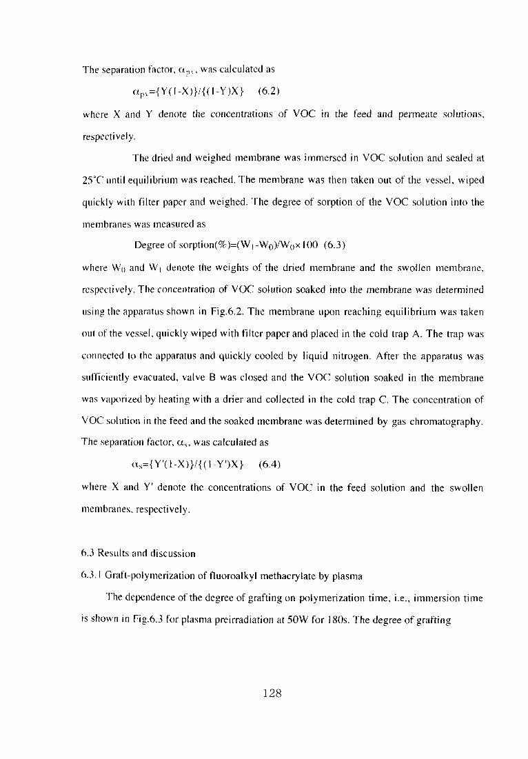
The separation factor、αpいwas calculated as
αp、={Y(1-X)}/{(レY)X} (6,2)
where X and Y denote the concentrations of VOC in the feed andρermeate soJutions、
respectivejy.
The dried and weighed membrane was immersed in VOC solution and sealed at
25°Cuntil equilibrium was reached, The membrane was then taken out of the vesse畳, wiped
quickly with fi且ter paper and weighed, The degree of sorption of the VOC solution into the
membranes was measured as
Degree of sorption(%)=(Wl-Wo)/Wo×100(6.3)
where W〔}and Wl deno重e the weights of the dried membrane and the swollen membrane、
respectively. The concentration of VOC solutめn soaked into the membrane was determined
tising the apparatus shown in Fig.6.2. The membrane upon reaching equilibrium was taken
out of the vesseL qしlick且y wiped with filter paper and placed in the cold trap A. The trap was
connected to Ihe apparatus and quick且y cooled by liquid nitrogen. After the apparatus was
s uf’fi ciently evacuated, valve B was closed and the VOC solution soaked in the membrane
was vaporized by heating with a drier and collected in the cold trap C. The concentration of
VOC soltition in the feed and the soaked membrane was determined by gas chromatography。
The separation factor, ots,was calculated as
al={Y’(1-X)}/{(i-Y’)X} (6,4)
where X and Y’denote the concentrations of VOC in the feed solution and the swollen
nnenibranes、 respectively。
6.3Res ults and discussion
6.3.lGraft-polymerization of fluoroalkyl methacrylate by plasma
The depelldence of the degree of grafting on polymerization time, i.e., immersion time
is shown in Fig.6.3 f6r plasma preirradiation at 50W for 180s, The degree of grafting
128

(ま)◎⊂遭σ」208」◎Φ∩
10
8
6
4
2
0
0 10 20 30 40 50 60 70
1mmerSe time(min)
Fig.6.3 Dependence of the degree of grafting on po畳ymerization time for plasma
preirradiation at 50W for l 80s.
129
increased with increasing Polymerjzation time and leveled off jn 60 minutes、 The
polymerization time was determined to be 60 minutes. The obtained degree of grafting was
around 7.5 wt%. The degree of sorption of HDFNMA in PDMS is I3 wt%. Only a part of
the HDFNMA sorbed into the PDMS membrane was grafted on the PDMS membrane。
6.3.2Characterization of the grafted PDMS membrane
The surt’ace morphoJogies of the grafted PDMS membranes were analyzed usjng their
XPS spectra。 The ratio of fl uori ne, oxygen, carbon, and silicon atoms were analyzed and
calculated fc)r-911m beneath the surface on the grafted PDMS membrane at 30°and 90°
photoelectron emissioll angles and are characterized in Table 6. L In this spectra, the
compositioll of atoms are determined up to a depth of 4.5 and gnm from the surface at the
phく)toelectron emission angles of 30°and 90°,respectively37. On the surface of the PDMS
membrane exposed重o the alrafter irradiatjon, the O/Sl and C/Si ratios increased. The surface
ofthe membrane was oxidized by oxygen or water vapor inthe alr.
Fig.6.4 shows the effect of the plasma power on the FISi,0/Si, CISi ratios for the
l80s plasma graft polymerization, The FISi and CISi ratios on the surface of the grafted
PDMS membralle increased with increasing p且asma power、 due to the graft polymerization of
HDFNMA by the plasma. The radical produced on the surface significant且y increased with
mcreaslllg p】asma power. Hence, the degree of grafting increased with increasing plasma
power. After graft polymerization, the residual radicals on the su㎡face of the membrane
reacted with oxygell()r water vapor in the air.
Fig.6.5 shows the effec{ of the p且asma irradiation time on the FISi and C/Si ratios for
the IOW plasma graft polymerizatiol1. The FISi and CISi ratios on the surface of the grafted
PDMS membrane increased with increasing Plasma irradiation time due to the graft
polymerization of HDFNMA by the plasma. The OISi ratio on the surface of the grafted
PDMS membranes leveled off in the irradiation tiIne of 60s. For a iong irradiation time, the
probab日ity of radical bonding reciprocally increased37. The radical produced on the surface
gradually increased with increasing plasma irradiation time. The degree of grafting and
130

Table 6.1 Fhlorlne to sHicoi1. oxgen to silicon and carbol1ωsilicon{童tomic
ratios for the surface of PDMS and grafted PDMS membranes b XPS王mal sis
Plasma graft condition
Power Exposure time
(W) (s)
ElectrOll
erntSslOn
angle(°@)
Atomic ratio“
F/Si o〆Si c/Si
30
00
3Qノ
0.0584
0.Ol74
1,18
1.36
1.63
1.74
60 30
X0
0.0355
0.0512
1.80
2.61
2.86
4.39
10
(Reverse side)
0039
0.OlO9
0.0106
1.19
1.35
L78
L86
180
0039
0.110
0.101
1.80
2.15
3、34
4.82
(Reverse side)
0039
0.0288
0.0268
1.29
1.3 6
L83
1.80
300
0039
0.0590
0.0869
1.71
3.OO
288
5.07
10
0039
0.110
0,101
1.80
2.15
3.34
4.82
30 180
00
つJQノ
O.136
0.102
L88
2.93
3.37
6.20
50
00
傷」9
O.0958
0.154
2,02
3.69
3.29
6.97
且O l80
under air after plasma exposure
:not grafted
90 b 1.60 121
PI)MS 90 h 1.42 1.85
a:FISi:Fluorine atomic ratio(%)/Silicon atomic ratio(%)
0/Si:Oxgen atomic ratio(%)〆Si}icon atomic ratめ(%)
CISi:Carbon atomic ratio(%)/Silicon atomic ratio(%).
bnot detected.
131

0.2
0.15
」0しり
_L
0.05
0
0 10 20 30 40
Power(W)
50 60
の\Q.一∪り\○
Fig.6.4 Effect of plasma power on FISi,0/Si, CISi of the membrane surface grafted for
I80s plasma preirradiation:(口)FISi;(◇)0/Si;(○)CISi at electron emission an91e of 90°.
132

の\」
0.2
0.15
0.1
0.05
0
0 50 100 150 200
Irradiation time(s)
250
8
7
6
5
4
3
2
1
0
300
の\O.一しり\○
Fig.6.5 Effect of plasma irradiation time on FISi,0/Si,CISi of the membrane
surfabe grafted at 10W plasma preirradiation.:(口)F/Si;(◇)0/Si;(○)C/Si at
e且ectron emission angle of 90°.
133

hydrophobicity then gradualSy increased with increasing plasma irradiation Iime. The
residual radicals after graft polymerization did not exist for a Iong time, The residua)radicals
oll the surface of the membrane did not significantly react with oxygen or water vapor in the
air.
The FISi,0/Si and CISi ratios〔m the reverse side of grafted PDMS membranes were
且ower than on the grafted surface. After the irradiation, the degassed HDFNMA was placed
in the reactor, and the PDMS membranes were soaked and grafted, The graft polymerization
was promoted in the grafted PDMS membrane37. The quantity of the radicals on the inside
alld reverse side of the grafted PDMS membrane was lower than that on the su rface. Hence、
重he degree of grafti屡〕g on the insjde and reverse side of the grafted PDMS membrane was
lower thall that on the su1face.
6・33The effects of the graft condition on sorption and pervaporation
We showsthe effect of the plasma power on the flux and separation factor for the TCE
solution during pervaporation through the PDMS membrane for a l80s plasma treatment in
Fig.6.6. The伽x of the grafted PDMS increased with increasing pEasma power. The
separation factor shく)wed a maximum at 10W and then decreased wlth increasing plasma
power. The radical produced on the surface was significantly increased with increasing
plasma power. The degree of grafting and oxidation were simultaneously increased. The
membrmle grafted at a weak power,10W, was not significantly oxidized very much. The
hydrophobicity of the grafted membrane was負maxlmum when the membralle was irradiated
at loW alld grafted.
We 9. hows. the effect of the plasma irradiation time on the fhux and separation factor for
the TCE solutioll durhlg pervaporation through the PDMS membrane at IOW plasma power
in Fig.6.7. The flux of grafted PDMS membrane was constant regardless of the plasma
irradiation time. The surface of the grafted PDMS membrane was not significantly oxidized.
The separation factor of the grafted PDMS Inembranes increased with increasing irradiation
time and the maximum was for Ihe l80s plasma treatment. The degree of grafting increased
134

0.25
0.2
じD lー
ロ
ー 0
(‘N∈\9)×⊇」
0.05
0
0 10 20 30 40 50 60
2000
1500
1000
500
0
(-)」80。5セo焉」8Φしり
Power(W)
Fig.6.6 Effect of plasma power on the伍lx and separation factor(αpv)for TCE-
water mixtures in pervaporation through grafted PDMS membrane for l 80s plasma
preirradiation.:([])0.005wt%feed concentration;(○)0.OIwt%, open:月ux,
closed:separation factor。
135

0.25
0.2
〔J lー
ロ
ー 0
(‘N∈\9)×⊇L
0.05
0
0 50
2000
(-)」oぢ。。芝ε。己」巴Φの
∩) ∩)
0 ∩) 0
5 ∩) 0
11 1 〔」
0
100 150 200 250 300 350
lrradiation time(s)
Fig.6.7 Effect of plas, ma irradiation time on the flux and separation factor(αpv)
tbr TCE-water mixtures in pervaporation through grafted PDMS membrane at
10W plasma preirradiation.:0)0.005wt%feed concentration;(O)0.01wt%,
opel1:flux、 c(osed:separatiGn fact()r.
136

(‘讐\ox)×⊇苗oト
×「∈」Φ罵〉》で⊂僑一邸りOト
0.025
0.02
0.015
0.01
0.005
01
(0.08よ讐0・06
も0.04y)0.02
0
0 0.01 0.02 0.03 0.04
TCE in feed(wt%)
Fig,6.8 Effect of feed concentration on the flux for TCE-water mixtures ln
pervaporation through PDMS membrane and plasma grafted PDMS membrane at
iOW for 180s.:(□)totai Hux;(◇)water伽x;(0)TCE fl ux. opetl:grafted
membrane、 c且osed:PDMS membrane.
137

with increasing plasma irradiation.The hydrophobicity of the grafted PDMS membranes was
effectively increased due to introducing the hydrophobic polymer, poly(HDFNMA)・
The刊ux as a functio雪10f the TCE corlcentration in the feed solution are shown in Fig.6.8 for
重he grafted PDMS membranes. For the PDMS and the grafted PDMS membranes, the water
伽xdecreased with increasing feed TCE concentration. In a previous study, fbr the PDMS
membranes grafted using HDFNMA by 6〔,Co irradiatiol1、 the water flux decreased with
increasing feed collcentration」n this study, the similar phenomena was observed. The TCE
伽xillcreased with increasing feed concentration. For the grafted PDMS membranes、 this
tendency was sign甫cant. The tota田ux consisted of TCE and water for the grafted PDMS
membrane increased with increasing feed concentration wh藍le the total刊しlx f()r PDMS
membrane decreased with increasing feed concentration. The PDMS membranes that grafted
wi1h HDFNMA and simultaneously oxidized by plasma-graft polymerization. had a high
seledivity for TCE
The relationships between the TCE concentration in the feed and permeate are show2}in
Fig.69 f〈)r the grafted PDMS membranes, For all the membranes, the TCE concentration ill
the perlneate increased with increasing feed concentration, and for the grafted PDMS
membranes, the tendency was signiflcant. The relationship between the feed concentration
and重he permeate coI)centration was observed to be Iinear. The pervaporation through the
gra負ed PDMS c〈)uld be used for easy quantitative analysis. The f6ed concentration can be
known by the meas恥lrement of the permeate concentration. The grafted PDMS membrane
had a lligh selectivity for VOCs. It is important to concentrate the VOC solutions for
quantitative analySiS,
The separation factor、αP、,as a function of the TCB concentration ill the feed solution
is shown ln Fig.6』Ofor the grafted PDMS membranes.αp、. was significantly increased
with increasing feed concentration for the grafted membranes.
ln the grafted PDMS membrane、 the best separation performance was, due to introducing
the hydrophobic polyl’ner, poly(HDFNMA>.
138

(ま妄)Φ罵Φ∈」Φα⊂己Oト
60
50
40
30
20
10
0
0
R=°・94974
/硯。
呪
O.01 0.02
R=0.9763
口
0.03
\ R=0.9752
O.04 0.05
TCE in feed(wt%)
Fig.69 Relationship between TCE concentration infeed and permeation in
pervaporation through PDMS and grafted PDMS membranes:(○)membrane
irradiated at亘OW for 180s and grafted,(△)membrane irradiated at l OW for 300s
and grafted;(◇)membrane irradiated at 10W for 180s and exposured in the air:
dコ)PDMS.
139

4000
3500
(3000,
とB25008? 2000
ε器 1500
虜1000
500
0
0 0.Ol O.02 0.03 0.04
TCE in feed(wt%)
0.05
Fig・6・10Separatioll fac亡or(αpv)as a function of feed concentration in
pervaporation through PDMS and grafted PDMS membranes:(0)membrane
irradiated at lOW for l 80s and grafted、(△)membrane irradiated at lOW for 300s
and grafted;(◇)meinbrane irradiated at lOW for l80s and exposured in the air;
(口)PDMS.
140

Tabie 62 Pervaporation data for various VOCs through PDMS membrane
and lasmaσrafted PDMS membrane aUOW for l 80s
VOC Membrane
TCE
PCE
Benzene
Toluene
Grafted membrane
PDMS
Grafted membrane
PDMS
Grafted membrane
PDMS
Grafted membrane
PDMS
Comp・sition(wt%)FJux Separation
Feed Permeate(σm⊃h l)factorαp・
O.015
0,015
0。0070
0。0079
0.017
0.016
0.0且4
0.014
20
7.0
14
5.6
31
7.5
22
6。8
30
、剰3731652857
1700
520
2300
740
2600
500
2000
530
The pervaporation results of dilute TCE, PCE, benzene and t(》luerle solutions throし且gh
the grafted PDMS membranes are shown in Table 6.2. The permselevtMty for VOCs
through the grafted PDMS membrane at lOW for 180s were high when compそlred蝋h lhe
PDMS membrane.
The degree of sorption of the VOC-water mixtures for the grafted PDMS membralles
are shown inTable6.3.
Table 6.3 Sorption data for various VOCs in PDMS membrane and plasma
σrafted PDMS membrane at 10W for 180s
VOC Membrane
VOC in feed Dcgrec of s、velling VOC in mcmbrallc Separatio富1
(wt%) (wt%) (wt「め ractorαs
TCE
PCE
Benzenc
Toiucne
Grahed membranc
PDMS
Gral㌃cd mcmbranc
PDMS
Graftcd membranc
PI)MS
Gra倉ed mcmbrane
PDMS
0.017
0.0】8
0.OlO
O.0085
0.0】3
0.014
0.Ol7
0.016
5-324481
2〔}
12
68
25
34
9.0
33
27
1500
720
2()1(X}
4UNX)
40XK)
61 0
29{X}
2400
141

The solubility of VOCs for the grafted PDMS membrane at lOW f6r 180s was high when
compared with the PDMS membrane. The grafted PDMS membrane that had the high VOC
concentrations in the sorbed solution showed the best separation performance.
6,4Conclusions
The PDMS membrane was improved by the graft polymerization wlth HDFNMA by
plasma, whlch had the effect on increasing the selectivity for VOCs. When the pervaporation
is used as analytical method、 i亡is expected that the relationship between the feed
concentration and the permeate concentration is observed to be linear as well as for PDMS.
The application to the analytical pervaporation through piasma-grafted PDMS membranes
was expected。
The degree of grafting was around 7.5wt%. The degree of sorption for the PDMS with
HDFNMA is l3wt%. On且y a part of the HDFNMA sorbed into PDMS membrane was
grafted ollto the PDMS membralle. The radicals on the surface were significalltly increased
with illcreasing plasma power. Hence, the degree of grafting increased with increasing
plasma power alld oxidation was also increased. The radical on the surface was gradually
increased with increasing plasma irradiation time. Hence, the degree of grafting and
hydrophobicity increased with increasing plasma irradiation. After the irradiation、 the
degassed HDFNMA was introduced into the reactor, the PDMS membranes were soaked in
HDFNMA and then graf重ed. The graft polymerization was promoted in the PDMS
membrane. The degree of grafting on the inside and reverse side of the PDMS membranes
was lower thall on the sL1躍face.
The flux of the grafted PDMS membrane increased with increasing plasma power. The
radical produced on the surface significantly increased with increasing plasma power. The
degree of grafting and oxidation simu量taneoしisly increased. The flux of the grafted PDMS
membrane was constant regardless of the plasma irradiation time. The degree of grafting
mcreased with increasing plasma irradiation。 The hydrophobicity of the grafted PDMS
142

m・mb・ane・w・・effecti・・1y illc・ea・ed due t・i・t・・duci・g the hyd・・ph・bi・p・1ynle・、
poly(HDFNMA). The solubility of VOCs represented by TCE, PCE, benzene aiid toluene
for the grafted PDMS membrane at 10W for l80s was significallt when compared with the
PDMS membrane. The grafted PDMS membrane thaI had the high VOC concentrations in the
sorbed solution showed the best separation performance, The permese且ectivity for VOCs⊂)f
the membrane was enhanced by the introduction of the hydrophobic polyn)er、
poly(HDFNMA)。
The relationship between the feed concentration and the per置neate concelltration was
observed to be linear. Because the grafted amount of the plasma grafted PDMS memblalle
was little and the advantage of rubbery PDMS membrane remained, the relationship belween
the feed concentratien and the permeate concentration wasく)bserved書o be linear. The feed
concentration is able to be introduced from the permeate collcentratk川. The pervaporation
through the grafted PDMS membrane could to be used f()r eas y quantitative analysis.
6.5Acknowledgments
The authors are grateful to Fuji Systems Corporation for providing the PDMS
membranes.
6,6Reference
DT.K. Poddar,ノ. me’nhr. Sci.,132,229(1997)。
2)J.B6rjesson, H.0.E. Karlsson, G. Tragard,ノ.〃zemhr. S(・~,, l I 9,229(1996).
3)A.Baudot, M. Marin, J,’11e〃ihr. Sci.,120,207 d 996).
4)N.Rajagoplan,ノ. me,nhr.5「d.,104,243(1995)、
5)K.Mecki, R.N. Lichtenthaler,ノ. memhr. Sci.,113,81(1996).
6)」.G. Wijmaηs, A.L. Athayde, R. Daniejs, J・H・ Ly, H.D・Kamaruddin, L Pinnau,ノ.
’11e’nhr. Sci.,且09,135(1996).
7)M.G. Liu, J.M, Dickson, P. Cote,ノ. Me〃~わr.∫ぐ’.,111,227 d 996).
8)T.Nakagawa, A. Kanemasa, Sen ’i Gakkaishi, 51,123 d 995)・
143

9)C.Dotremont. B. Brabants, K, Geeroms, J. Mewls, C. Vandecasteele,ノ。ル1e〃ihr. S(・i.,
亘04,109d995).
10)C.Visvanathan, B. Basu, J.C. Mora,1nd, Eng. Che〃1. Res.,34,3956(1995).
11)SB. McCray, D.T. Friesen, D.D. Newbold, R. Ray, D.L. M川ard,Proc 7th
1’1’ern‘’〃θn‘’1 Cθ’1f診rence on 1)ervaporation I)roce∬加’he chemica〃月脇’∫耽y 1995,422,
Oregon(1995).
12)D.Yang, S. Majumdar. S. Kovenkljog】u, K.K. Slrkar,ノ.ル1e’nbr. S(・i.,103,195
d995).
13)K.Ogasawara, T. Masuoka, T. Iwatsubo, K. Mizogichi,Ground warter,37,47
(1995).
14)J,Schauker,ノ. Aρρ1. P‘,1y〃1.∫c’.,53,425(1994).
15)C.Dotremont. S。V.D. Ende, H. Vandomme且e, C. Vandecasteele, Desat〃tcltiθn,95、91
d994).
i6)P.J. Hickey、 C.H. Gooding,ノ.ルfe〃ihr.5(ゴ.,88,47(1994).
17)PJ,Hickey、 CH. Gooding,ノ. Me〃ihr. Sci.,97,53(1994).
18)T.Yaaguchi, S. Yamahara, S. Nakao S. Kimura,ノ. Membr. Sci.,95,39(1994).
19)S.GQethaert, C.Dotremont, M.Kuijpers, M.Michels, C.Vandecasteele,ノ. Me’nbr. Sci.,
78、135(1993).
20)B.K. Srinivas, M,M. El-Halwagi, Computers Chem. En8n8.,】7,957(1993).
2DA.RJ. Andrews, A. Zlatkis, M.T. Tang, W. Zhang, H. Shanfield, Environ. Sci.
7セ(・1~’~θL.27,ll39(1193).
22)M.しJacobs. R.W. Baker、 J, Kaschemekat, V.L. Simmons, Air(隻Wasteルfana8e’nent
Assθ(ゾα〃θ’~A〃’~照’ルlee”ng(蔓E.vhihi’~otl,86,1,Denver(1993).
23)M.Hoshi,T. Saito, A. Higuti,T, Nakagawa. Sen’i GakkaiShi,47,644(1991).
24)W・W・Y・Lau. J. Finlayson. J.M. Dickson, J. Jian9, M.A. Brook,ノ.〃2e’nhr. Sci.,134,
209d997).
25)C.Leger、 H.D.L. Lira. R. Paterson,ノ. membr. Sci.、120,135(1996).
26)D・Roizard、 R. Cl6fnent, P. Lochon,J. Kerres, G. Eigenberger,」「.〃le〃ibr.∫d.. n 3,
144

151(1996).
27)T.Nakagawa,ルfak〃(me’ηわrα’le♪,20.156(1995).
28)M.Nakamura、 S.Samejima, T. Kawasaki,ノ, Me〃ihr.∫(ゴ.β6,343 d988).
29)Y・Fang・V・A・Pham・T・Matuura, JP. Santerre、 R.M. Narbaitz.ノ. A〃1. Pθ~ll.∫(・i.,
54,且937(且994),
30)K,Jian, P.N. Pintauro、 R。 Ponangi,ノ,,ne〃1わr. S(ゴ.. I l7, l l7G996).
3DS. Mishima, T. Nakagawa,κ‘,わt〃ishi Rθ〃ht〃ls/IU、54、2n(1997).
32)S.Mishima, H. Kaneoka, T. Nakagawa, The 4〃z 1θル〃~∫1C/1~’i As~‘’, C-29(1997),
33)S.Okamoto,ルlakbl (me’nbrane),14,277(1989).
34)A.Charlesby, Atomlc radiatめn and polymers, Pergamon press LTD.,England,UK
(1960).
35)C.量hm, S. Ihm,ノ. Me〃ibr. Sci.,98,89(1995)。
36)T.Hirotsu,ノ. Aρρ1. Pθ’y’η. Sci。,34,1159(1987).
37)The soclety of Polymer Science, Japan, Shin koubunshi」ikkengaku(experimeiital
method in polymer science)voL lO;inJapan, Kyoritsu press Ltd..Tokyo d995).
145

Chapter 7. Sorption and Djffusion of Volatile Organic Compounds in
Fluoroalkyl Methacrylate Grafted PDMS Membranes
7.1lntroduction
Volatije organic compounds have been considered toxic in the human body. Recently.
it was foしmd to a social problem that ground water and soil are contaminated with volatile
organic compounds(VOCs)12.
Pervaporation has been is known as the superior method when applied to the
puri伽ation of contaminated water alld the extraction of aroma compounds, etc., and has
been wideiy studied】’B。 Theρredictlon of permeation is important fbr the treatment,
extractioll and quantitative analysis by pervaporation. To account for the permeation through
the ll()n--porous membrane, a sorption-diffusion mechanism ls important factor. For
predicting permeation, a sorption-diffusion inechanism is proposed and has been
Studied 14、〕9.
The need for hydrophobicity data in the studies of organic colnpounds can be traced
back at least to the turn of the century. The hydrophobicity is used to indicate the physical
property of the molecu且e which governs its partitioning into the non aqueous portion of an
immisclble or partially immiscible solvent pair2〔}. According to Nernst2〔}, the partition
coet’ficient can be simply described as:
P=Co/Cw or logP=logCo-bgCw (7」)
where Co and Cw represent the molar concentrations of the partitioned compound in the
organicand aqueousρhases、 respectively.
The octano亘一water partition coefficient(Pow)has been generally used in expressing
hydrophobicity. The hydrophobicity、 Pow. is closely related to the solubihty of organic
COiilpounds21,
Also、 the molecular volume is closely related to the diffusjvity of organlc compounds,
The molecular volume is important for the diffusivity of the permeability,
Polydimethylsiloxane(PDMS)is well known as an excellent polymer membrane
146

material based on its high permeability to gases and liquids22.且t is desirabie to ellhance the
selectivity of PDMS fbr VOCs and has beell studied23-28. Ftuorinated poiymers have been
studied as organic compounds due to its hydrophobicity based on the low surface
energy29、31・It is expected to synthesize a nlore useful nlelllbrane inaterial by coiiibinins)the
PDMS and伽orinated polymer using graft polymeri zation and investigated in this study.
In chapter 3, the result was obtained that the solute properties and interactk、n effected
on the permeation behavior・In this chapter, the PDMS membralles were improved by the
Plasma-grafting of fluoroalkyl methacrylates(FALMA)to enhance the affi El i ty of PDMS to
VOCs. Furthermore, the pervaporation through the plasma.grafted PDMS membralle alld the
solution-diffusion mechanism for various VOCs based on their pro pe rties were investigated.
7.2Experimental
7.2」Graft polymerization of fl uoroalkyl methacrylate by piasma
Table 7」Phisico-chemical properties of volatile organic compotltlds(>OCs)
(ompound Abbreviation Formula
S olubilit、 inwa【cr
Molccular at 20℃
、、.cigh1 (、、重つ多)
Trichk)r(x}thylene
Tetrachloroeth}.lenc
Benzene
「『01uenc
Fthyl butanぐ}a〔e
Eth l bcnzoate
TCE
PCE三1
EBU
EBZ
CHCI=CCI2
CCI 2=CCI 2
C6H6C6H5CH 3
CH 3(CH 2)2COOCH 2 CH 3
C6H5COOCH 2 CH 3
131.89
165.83
78.ll
92.13
116.16
15().2
o,II
{}.〔)15
0.181
0.047
0.68
0.08
a:Thc anαher namc of Tetrachloroeth}’1ene is Pcrchloroc〔hylcnc.
147

Commercial PDMS membranes(Fuji Systems Corporation).50μm thick, were used
throughoul this work. I HJ H,9H-hexadeca伽oronony且methacrylate(HDFNMA)(Daikin
Fine Chemical Laboratory Corporation)were used as received to avoid homopolymerization.
trichbroethylene (TCE), tetrachloroethylene (PCE), benzene, toluene, ethyl butanoate
(EBU), ethyl benzene(EBZ),2-propanol and acetone(Speciat grade,Wako Pure Che【nical
lndustries, Ltd,.)were used as received. The phisico-chemical properties of VOCs used in
this study were shown inTable 7」.
The plasma grafゆ01ymerization was performed as reported by C. Ihm et aL32 and T。
Hiritsu 33. and a schematic diagram of the apparatus is shown in Fig.7.1.The PDMS
membranes ug. ed inthis study had stick to glass. To treat one surface, PDMS membranes of
7×7cm were placed in a flask without any spaces between the surface and the glass of bottom
not to introduce air. The PDMS membranes in a flask were under vacuum overnight. Ar gas
was then introduced into the flask. The flask was next evacuated. The introduction of Ar gas
and evacuation was repeated several times. The membrane was treated by 13.56MHz p且asma
and at 10Wfor l80s. The membranes were then contacted with HDFNMA in the liquid
phase aI 60℃for l h. After the polymerization stopped, the membranes were rillsed in
acetone overnight to remove the homopolymers and any nonreacted monomers, then dried
for 48 hours inan evacuated vesseL
ln this chapter、 seven sheets of membranes were subjected to the treatment The degree
of grafting was calcuiated as
Degree of grafting(%)=(WレWo)/Wo×100(7.2)
where W〔}and Wl denote the weight of the PDMS membrane and the grafted PDMS
membrane, re9・ pectively. The coefficient of standard deviatlon (Vs) fbr their degree of
grafting was O.32, Among them, the Vs of three samples was O. IO. Therefore, the three
samples were provided to the subsequent inves重igation. The average of the degree of grafting
for the three samples was 7.Owt%.
148

Vacuum
4Ar gas
ψ
1 3.56MHz RF plasma
generator and
matching network
<咽トDegassed monomer
Fig.7, l Apparatus for the graft polymerizatjon by plasma.
149

7.2.2 Characterization〔)f the grafted PDMS membrane
X.rayρhotoeiectron spectroscopy(XPS)spec1ra were obtalned using an IPS-9000SX
(JEOL, Ltのwjth MgKαexciting radiation(1253.6eV).The X。ray gun was operated at
IOeV wiIh a samp】e chamber vacuum of less than 5x】α9 Torr. The XPS spectra were
recorded at tw(, electron emission angles(走})of 30°and 90°.
7.2.3Pervaporation expe ri ment and sorption musurement
The pervaporation experiments were performed in a previous study23’25 using the
colltil)UOUs.fセed type at 25℃. The feed solution was circulated through the cel(and the feed
tank. The grafted surface of the membrane was keeping in touch with the feed solution in the
cell. The effective membrane area in the cell was l9.6 cm2. The pressure an the permeation
side was kept below IOTorr by vacuum pumps. Upon reaching steady state flow conditions、
the permeate was col且ected in traps cooled by liquid nitrogen(-196℃)at timed intervals,
isolated from the vacしium system, and weighed. The permeation rate, flux(J), was obtained
usillg eq.(7.3)
J=QIAt (7.3)
where Q is the amount that permeated during the experimental time interval, t, and A is the
effective surface area. The VOC and water flux were calculated from the total flux and the
permeate colllPOSitiOII, The concentration of VOC in the feed and permeate so且ution was
determined by gas chroInatography using an FID detector. The VOC concentration in the
permeate was high, which is far beyond its solub田ty且imit in water, The phase separation
took place ill the permeate.2-propanol was added to the permeate solution. The permeate
solution was homogenized and analyzed to determine the VOC concentration, The separation
factor, apy, was calculated as
αp、={Y(1-X)}/{(1-Y)X} (7.4)
where X and Y denote the concentrations of VOC in the feed and permeate solutions、
respectively.
150

Vacuum ↑
A
○
A:cold trap for membrane
B:valve
C:cold trap for collecting samples
Fig.7,2 Apparatus for the composition measurement inthe membralle.
The dried and weighed membrane was immersed in VOC solution or VOC liquid and
sea】ed at 25℃until equi且ibrium was reached・The membrane was then taken out of the
vesse】, wjPed quickly with fjlter paper and weighed・The degree of s()rption or VOC liquid
of the VOC solution into the membranes was measured as
Degree of sorption(%)ニ(WI-Wo)/W〔lx且00 (7.5)
151

where Wo and Wl denote the weights of the dried membrane and the swolleII membrane、
respectively. The concentration of VOC solution soaked into the membrane was determined
using the apparatus shown in Fig,7.2. The membrane upon reaching equilibrium was taken
out of the vessel,quickly wiped with fi且ter paper and placed in the cold trap A. The trap was
connected to the apparatus and quickiy cooled by iiquid nitrogen. After the apparatus was
sufficiently evacuated, va且ve B was closed and the VOC solution soaked in the membrane
was vaporized by heating with a drier and co11ected in the co且d trap C. The concentration of
VOC solution in the feed and the soaked membrane was determined by gas chromatography
same as pervaporatlon experlment. The so畳ubility coeftlcient(K)and the separation factor
during sorption,αs、 were calculated as
K=Y7X (7.6)
αs={Y’(1-X)}/{(1-Y「)X} (7.7)
where X and Y’denote the concentrations of VOC in the feed solution and the swollen
tneinbranes. respectively.
7.3Results and discussion
7.3.lCharacterization of the grafted PDMS membrane
The surface morphologles of the grafted membranes were analyzed using the XPS
spectra. The ratio of fluorine, oxygen, carbon, and sihcon atoms were analyzed and
calculated fc)r~9 nm beneath the surface of the grafted membrane at 30°and 90°
photoelecti℃m ernission angles and characterized in Table 7.2. In these spectra. the
composition of atoms are determined up to 4.5 and gnm deep from the surface at the
photoe且ectron emission angles of 30°and 90°. respectively3-↓. The FISi ratio on the reverse
side of the grafted membranes was lower than on the grafted surface. The OISi and CISi
ratios oTl the reverse side of grafted membranes were almost same as on the grafted surface.
The degree of grafting for whole membrane was 7.Owt%. The thickness of grafted PDMS
membralle was a1lnost the same as untreated PDMS membrane. After the irradiation、 the
152

Table 7・2 Ft uori ne to silicon, oxgen to silicon and carbon to silicon atomic
ratios for the surface of PDMS and grafted PDMS membranes b XPS al)al sis
Pla9・ ma graft condition
Power Exposure time(W) (s)
Electron
ern」SS10n
an9且e(° j
AtomiC ratio・’
F/Si o/Si C/si
10 180
00
3Qノ
0.目0
0.IOI
L80
2.15
3.34
4.82
(Reverse side)
00
つJQノ
O.0288
0.0268
1.2c)
1.36
L83
1.80
10 180
under airafter plasma exposure
:not grafted
90 b1.60 1.21
PDMS 90 、ヒ L42 1.85
a:FISi:Fluorine atomic ratio(%)/Silicon atomic ratio(%)
0/Si:Oxgen at・mic・ratio(%)/Silic・n at・mic・ratio(%)
CISi:Carbon atomic ratio(%)/Silicon atomic ratio(c/o).
b not detected.
degassed HDFNMA was introduced into the reactor, the PDMS membranes were s{}aked iil
HDFNMA and grafted. The graft polymerizatjon started with the su rfa ce of membヨηne and
was cユused in the PDMS membrane. Hence, the degree of grafting oll the inslde and reverse
side of the PDMS membranes was lower than on the surfd’ ce.
7.3.2Effect of the VOC properties on the pervaporatioll
The pervaporation properties of various VOC aqueous solutk)ns were determllled in this
study. The total flux as a function of the VOC concentration inthe feed sohllion are showi】in
Fig.7.3 for the PDMS membrane and the grafted PDMS membrane. Except for benze[1e,
when feed VOC concentration increased, the total伽x was almost c()nstant in the PDMS
membrane. For benzene、 the total flux increased with the feed concentration inthe PDMS
153

一㎝鼻
0.15
㎝ 05
0
(=Nε\9)×コ己
)a
鏑◇
0.05
0.04
?
讐O・03
喜)蚤0.02
E
O.01
)b
今)。
・〆ロ ーvO
pm-v_配二茎二三、
▽ ▽
0 0
0 0・Ol O.02 0・03 0.04 0 0.01 0.02 0.03
VOC in feed(wto/o) VOC in feed(wt%)
Fig.7.3 Effect of feed concentration on total flux for VOC-w…韮er mixtures duri㎎pervaporation山rough a)PDMS
membrane, and b)grafted PDMS membrane.:([)TCE,(◇)PCE、ρ)Benzene, (A)Toluene,(×)EBU,(〉)EBZ.
O.04

一もnα
0.02
2NE O.015
b5 0.01蚤じ
QO.0050>
0
0.15
2N∈ib O・1己
善
= 0.05 6 kl
O
)a
○
○
口
弟9-一一一’・・’-x“’一一’一
0.02
2N O,015∈
もー 0.01
至ら
uO.0050>
0
0.05
2N O.04∈
90.03 ≦0.02
茎筍 0.01≧
0
)b
o一騨
0 0.01 0.02 0.03
>OC in feed(wt%)
0.04 0 0,01 0.02 0.03
VOC in feed(wt%)
Fig.7.4 Effect of feed concentra〔ion on water and VOC fl ux for V(:)C-water mixtures during pervapora正ion
th・・ugh・)PDMS In・mb・an・、・and・b)graft・d PDMSm・mb・…,:(ロ)TCE、(◇)PCE、(○)B・nzen・、(△)T・1・・n・,
(〉ぐ)EBU、(∀)EBZ.
0.04

membralle. For the HDFNMA grafted membranes, the tota且臼ux was a量most constant whell
the feed V()C concentration increased.
The water flux and VOC flux as a function of the VOC concentration in the feed
g. ol ution are shown in Fig.7,4 for the PDMS membrane and the grafted PDMS membrane.
Except for benzene、 when the feed VOC concentration increased, the water flux was almost
constant in the PDMS membrane. For benzene, the water flux increased with feed
concentration in the PDMS membrane. This results inthe total fiux being increased with feed
benzene concentration in the PDMS membrane.
To accoullt for the permeation of the mixture, the penetrates and membrane interact
each others and one component affects the transport of the other componentl9, The diffusion
of moleci】les are promoted, or inhibited by another component. Huang et. al.35・36 proposed
permea塗ion ratjo(f})which represent the ratio of actual flux to ideal fl ux, that is, the
interaction of one component with the other component or the membrane.寸}is described as
I‘)・=J/J{} (7.8)
Where J and J。 represent the actua田ux and the idea田ux, respectively. whell f}>1,the
transport of the componellt is promoted. when舟く1,the transport of the component is
inhibited. ll叩ervaporation, the membrane can be swollen by the penetration of components
and the diffusion is promoted. In this case, the water flux was affected by benzene and
mcreased with feed benzene concentration. Whi且e the feed benzene solutioll used in this
study was dilute aqueous solしltion, it may be considered that the swelling effect by benzene
affecled the permeation of water. ln the HDFNMA grafted membranes, the water月ux was
almost constant with increasing feed concen重ratlon of the VOCs. The promotion of the water
transport was not observed. h our previous studies24・25, fbr the membranes grafted with
fluoroalkyi methacrylate, the diffusion of water was prevented and the water flux decreased
with increasing feed concentration.夏n this chapter, the diffusion of water in benzene so{ution
was not promoted ill the HDFNMA grafted PDMS membranes, wMe the diffusion of water
in benzene solution was promoted in the PDMS membranes. Grafted HDFNMA inhibited
the increase c)f water刊ux.
156

一㎝刈
60
50
A婁}40患婁30歪5 20
9 10
0
)a
(ま妄)Φ罵Φ∈」Φα⊆こO>
)b
0 0.01 0.02 0,03 0,04 0.01 0.02 0.03
VOC in feed(wt%) VOC in feed(wt%)
Fig.7.5 Relationship b etween VOC concentration血feed and permeati on duri㎎pervaporadon through a)
PDMS membrane、and b)grafted PDMS membrane.:(口)TCE、(〈〉)PCE、(0)Benzene,(△)Toluene,(X)EBU,
(’17)EBZ.
0.04

The VOCs月ux was increased with the feed concentration in both the PDMS
membrane and the grafted PDMS membrane.
The relationships between the feed concentration and the permeate concentration are
shown in Fig.75 fbr the PDMS membrane and the grafted PDMS membrane. The VOC flux
increased with the feed concentration in both the PDMS membrane and the grafted PDMS
membrane. In the grafted PDMS membrane. the best separation performance was due to
introducillg the hydrophobic polymer, poly(HDFNMA). The permselectivity for PCE and
toluene was high in both the PDMS membrane and the grafted PDMS membrane. The
permselectivity for EBU and EBZ was low in both the PDMS membrane and the grafted
PDMS membrane.
The pervaporation properties of TCE and benzene mixed aqueoし量s solutions were
studied, The flux as a function of the TCE concentration in the feed solution is shown in
Fig。7.6 for the PDMS membrane and the grafted PDMS membrane. The feed benzene
collcentratioll was fixed at O.Ol5wt%. For the PDMS membrane, when the feed TCE
concentration increased, the water flux and the benzene flux were almost constant. The TCE
tl ttx increased with feed concentration. Hence, the total flux increased with feed
concentration. The relationship between the TCE fiux and feed TCE concentration of this
TCB-benzene-water mixture was almost same as the relationship between the TCE flux and
feed TCEconcentration of the TCE-water mixture. Benzene did not affect the permeation of
TCE in the PDMS membrane. For the grafted membrane. the pervaporation property of TCE
and benzelle mixed aqueous solutions was different from the PDMS membrane. The water
flux decreased with increasing feed TCE concentration over TCE=0.02wt%. The TCE flux
mcreased with feed coIlcentration, and the the increase was keep down at a high feed
concentratbnjn the grafted PDMS membrane. The benzene flux decreased with increasing
feed concentration。 The total flux decreased with increasing feed TCE concentration over
TCE=0.02wt%, For the pervaporation property iI) the grafted PDMS membrane. TCE
158

一㎝⑩
a) b)
0.05 0.05
( 0.04 ( 0.04
二 」: へ
ξO.03 ξ0・03こD ゆぎ y
支0.02 ζ0・02ニコ ニコ
」0.01 LO.01 0 0
0.015 0.015
証0.01 ε0.01∈i E\ \
σ》 こカメ y
×0.OO5 ×0.005 つ ⊃
]」 」」
0 0
0 0.01 0.02 0.03 0.04 0 0.01 0.02 0.03
TCE in feed(wt%) TCE in feed(wt%)
Fig.7.6 Effect of feed TCE concentratiofl on flux for TCE-Benzene-waLer mixture dudng pervaporation through
、)PDMS memb,an・.・and b)9・aft・d PDMS m・mb・an・aこ0、015wt% feed b・・zen・c・・centr・・i・n・:ρ)T・Ut i(◇)
water.(○)TCE、(△)Benzene,
0.04

一〇〇
0.05
)a
EO.04NξO.03
9× 0,02
⊇L O.01
0 5
0
0
00
5000
0
(f∈\9)×εΦ⊆ΦN⊆Φ゜D
(‘N∈\ox)x⊇」
0.05
0.04
0.03
0.02
0.01
0
5 1 5 0
1 0 0
の α の
0 0
(f∈\9)×コ鴫ΦにΦN⊆Φ゜o
)b
⊆L_ロ』 ◇
0 0.01 0.02
Benzene in feed(wt%)
0,03 0.04 0 0.01 0.02
Benzene in feed(wt%)
0.03 0.04
Fig。7.7 Effect of feed b enzene concentration on flux for TCE-Benzene-water miXture during per・vaport-on
th・。・gh・)PDMS m・mb・an・、・and b)graft・d PDMS m・mb・…at O.015wt%feed TCE…cent・al・i….:(ロ)T・tal,
(◇)water,(○)TCE,(△)Benzene.

quantity sorbed illto the membralle was very high due to introducing the hydrophobic
polymeL HDFNMA・so that the diffusion of water and benzene was prevented、 in tur11. the
flux decreased・Compared with the pervaporation for the TCE-water mixture, the TCE flux
fbr the TCE-benzene-water mixture was iow. The TCE fhlx was preven紀d by benzene
during Pervaporation of the TCE-benzene-water mixture. Duril19 Pervaporation fく)r TCE-
benzene-water mixture through the grafted PDMS membralle. the comp史川11ds which
permeate interfere each other.
Next, the feed TCE concentration was fi xed at O.Ol5wt%a1)d the feed benzene
concentration was varied. The flux as a function of the bellzene concen重ratioll itl艦he feed
solution is shown in Fig.7.7 for the PDMS membrane and the grafted PDMS membrane. Fc)r
PDMS membrane、 the water flux and the TCE伽x were almost constant when the feed TCE
concentration increased. The benzene flux increased with feed concentration, The Total tlttx
were almost constant when the feed TCE concentratio旧ncreased. While the water flux
increased with feed benzene concentration during pervaporatlon of benzene-waIer nlixtul-es.
the phenomenon was not observed for benzene-TCE-water mixture through PDMS
membrane. TCE molecu且es prevented the rise of water利ux,
For grafted PDMS membrane, the water flux decreased with increasillg feed
concentration. The TCE flux were almost constant when the feed TCE concelltration
increased. The benzene flux lncreased w虻h feed concentration. The total flux were almost
constant when the feed TCE concentration increased. For the pervaporati()n of benzene-water
mixture through the grafted PDMS membrane-he promote of water permeation was
prevented. In addition to that, TCE molecules inhibited the rise of water flux during
pervaporation of benzene-TCE-water mixture through the PDMS membralle・lt is considered
tha重during pervaporation of benzene-TCE-water mixωre through the graf建ed PDMS
Inembrane, both of grafted HDFNMA and TCE molecules prevented the permeation of water
inoleCUles.
7.3.3Effect of the VOC propelties on the sorptlon
161

The sorptめn isotherms for山e VOCs are presented in Fig.7.8 for the PDMS
membrane and the grafted PDMS membrane, respectively. The relationship between the feed
collcentration and the concentration in PDMS membranes was observed to be且inear. For the
grafted PDMS membranes, the concentration of VOC solution soaked into the membrane
was significantly increased with increasing feed concentration. The sorption selectivity for
VOCs was h重gher in the grafted PDMS membrane than in the PDMS membrane. As the
consideration of characterlzation, the graftlng started with the sur£ace of membrane and was
caused into the PDMS membrane-t is considered that the introducing hydrophobic
HDFNMA to the PDMS membrane make the sorption selectivity enhanced. The grafted
PDMS membrane that had the high VOC concentrations in the sorbed solution showed an
excellent separation performance. The solubility for PCE and toluene was high in both the
PDMS membrane and the grafted PDMS membrane. The so且ubility for EBU and EBZ was
low in both the PDMS membrane alld the grafted PDMS membrane,
The need for hydrophobicity data in the studies of organic compounds can be traced
back at least to the turn of the century. The hydrophobicity is used to indicate the physlca)
property of the molecule which governs its partitioning into the non aqueous portion of an
immiscib且e or partially iminiscible solvent pair. Pow, the partitioll coef石cient between water
and l1-octanoL expressed the hydrophobicity of the compounds.
T⊥amer et. aL21, considered the relationshjp between the IogPow of aroma
compoしmds and their solubility for PDMS membrane. The hydrophobicity, Pow, is closely
related to the solubility of organic compounds21.The solubility coefficient(K)represent the
9. ol lbility of organic compounds for membrane. The decimal logarithms of the sohlb川ty
coefficient(K)as a function of the IogPow are shown in Fig.7.9 for the PDMS membrane
and the grafted PDMS membrane. The solubilitiy(logK)for P℃E and toluene which have a
hlgh logPow. were high in both the PDMS membrane and the grafted PDMS membrane, The
s olubiiity(logK)tbr EBU which have low logPow was low in both the PDMS membrane
and the grafted PDMS membrane.
162

一〇ω
(ま峯)Φ器」Ω∈Φ∈⊆こO>
)a
妄)Φ⊂・5益∈Φ∈⊆こO>
)b
O O.020.040.060.08 0.1 0.120.14 0 0.020.040.060.08 0.1 0.120.14
VOC in feed(wt%) VOC in feed(wt96)
Fig.7.8 S orption of VOC on P D MS membrane as a fun(尤ion of the feed concentration at equilibrium for a)PDMS
membrane、 and b)grafted PDMS membrane.:(□)TCE,(◇)PCE、(○)Benzene.(△)Toluene、(×)EBU,(▽)EBZ.

巻o
4
3.5
3
2.5
2
1.5
1.5 2 2.5 3
IogPow
Fig. 7.9 Relationship between the hydrophobicity of VOC and the sorption in grafted PDMS
membrane.:([])TCE,(◇)PCE,(○)Benzene,(△)Toluene、(〉く)EBU、(▽)EBZ、 open:
for PDMS membrane, closed;for grafted PDMS membrane.
164

Tabl・7・3 S・・pti・n and dff・・i・・d・t・・f va・i…VOC・f・・PDMS alld g・’・ft,d PDMS
membrane
1)cgrcc(、f s(、rp【k}n ScP三斗ra竃k}ll
in PDMS mCmbrこIIlc Mdccular、olし」mc ttlctOl’
c°mP…dl・9】’(>w k・gK 〈m・DPI)Ms-lo{}9}{・・ゴ,1。n 、α口
PDMS grdft・d PDMS PI)MS gmrl・d円)MS
rnCinbranc nlenlbrane n}enibrt【nC 111Cll、hl・unc
TCE
PCE
Benzcnc
TolUenc
EBU
EBZ
L91
2.638
2.103
2.626
L805
2.602
2.71
3..↓8
2.55
3.28
2.40
1.76
3.25
4,20
3.42
3.63
2.89
2,27
2,〔〕4
1.60
1.〔}5
1.4s
134
0,154
9〔1.i)
102
88.9
1(}6
132
144
⇔、70「
o,口l
e、999
0.2】4
0.934
0、MI
〔[,918
{}.B㍉
{}.809
0,611
〔}.962
〔}.9、lS
The solubility(logK)for EBZ was low in both the PDMS membrane and the gr{lned PDMS
membrane, whiie EBZ has a high bgPow. Then, the ability of penetrate’br V()Cs ill
membrane was investigated. The degree of sorption for the pure VOC liquid in the
membranes are shown inTable 7.3. The degree of sorption for TCE, PCE, benzelle, toluene
and EBU are above 80wt%(above lmol/PDMS-100mg). The soiubility fく)r compく)しmds in a
membrane isaffected by its dispersion and polarization. Polarization can be considered usillg
the Pow value. The abllity of dispersion isdetermined by diffusivity. The degree ol’sorplic〕n
for EBZ was iow,23.lwt%(0.154mol/PDMS-lOOmg). The molecular voh1Fne of EBZ is
much greater than the other VOCs,therefore, the diffusMty of EBZ ls Iow. Hence. the
degree of sorption for EBZ was low and the solubility for EBZ was low inthe membrane,
7・3.4Effect of the VOC properties on the diffusion
Pervaporation pe1formance of a membrane is determined by both the sorption and the
diffusion characteristics of the permeating components in the membrane.
The relationship between the separation factor during permeatjon(αp、♪. the seρaration
factor durlng sorption(α5), and the apParent separation factor during diffusion(αD)is given
165

by Eq.(7.9)・
αP、=αs・αD (79)
αDisdescribed by Eq.(7」0)using Eq.(7.4),(7.7)and(79).
αD={Yd-Yり}/{(1-Y)Yl} (7.10)
where Y and Y撃denote the concentration of VOCs in the permeate solution and in the
swollen membranes for the same feed solution, respectively.αD was calcuiated by
Eq,(7.10)using the sorption isotherms in Fig.7.8 and the pervaporation in Fig.7,5。αD as a
flJnction of the VOCs concentration ill the feed solution is shown Table 7.3 for the PDMS
membrane and the grafted PDMS membrane, respectively. The diffuslvity for benzene and
EBU was higll in both the PDMS membrane and the grafted PDMS membrane. The
diffusivity for PCE waslow in both the PDMS membrane and the grafted PDMS membrane.
The molecular vo且umes andαD of the VOCs are shown inTable7.3. The molecular voiumes
of benzene alld EBU are much smaller than the other VOCs that their diffusMties is high.
PCE has four Clswith so量arger molecular volume, therefore, the diffusivity isvery low,
Permselectivity determined by the sorption and the dlffusion characteristics of the
permeatillg components in the membrane. The permse[ectivity of PCE and toluene were
high. Because the molecular volume of the VOCs is grater than water and the permeate
quickly pelletrates in a rubbery membrane Iike PDMS, permselectivity was not affected by
the diffusivity. Solubility significantly affects the permselectlbity during pervaporation
through hydrophobic rubbery membrane.
7.4Conclusions
The pervaporation properties of various VOC aqueous solutions through the grafted
PDMS membraRe were studled in this investigation. The pervaporation performance of a
mernbrane is determined by both the sorption and the diffusion characteristics of the
perme日tmg components in the membrane. The sorption and diffusion for VOC-water mixture
during pervaporation through the PDMS membrane and HDFNMA grafted PDMS
166

membrane were studied.
ln the grafted PDMS membrane, the best separatioll performance was due tく)
introducing the hydrophobic po且ymer, poly(HDFNMA). During pervaporation、 the
components which permeate and membrane interface each others. The phenon)enon was
significantly observed in pervaporation fbr the ternary mlxture through the grafted PDMS
membrane。
The sdubilitiy(logK)for PCE and toluene which have a high logPow. were high in
both the PDMS membrane and the grafted PDMS membrane. The solubility(k)gK)for EBU
which have low logPow was Iow in both the PDMS membmne alld tlle grafted PDMS
membrane. The solubility(logK)for EBZ was low in both the PDMS membrane alld the
grafted PDMS membrane, while EBZ has a high logPow. The solubi且ity for c()mpoullds in a
membrane is affected by its dispersion and polarization. Polarization call be considered usillg
the Pow value. The abihty of dispersion isdetermined by diffusivity. The degree of sorptioll
for EBZ was low compared to the other VOCs. The molecular voh置me of EBZ is much
greaterthan the other VOCs,therefore, the diffusivity of EBZ is low. Hence, the degree()f
sorption for EBZ was low and the solubility for EBZ was low in the membrane. PCE has
four Clswith a much larger molecular volume. therefore, the diffusivity is very low.
Permselectivity is determined by the sorption and the diffusion characteristics of the
permeating components in the membrane. The permselectMty of PCE and toluene was high
in this study. Because the molecular vo】ume of the VOCs is grater thall water and the
permeate quickly penetrates in the rubbery membrane like PDMS, permselectivity was n(,t
affected by diffusivity. Soiubiiity signif董cantiy affects the pernlselec{ibity during
pervaporation through the hydrophobic rubbery membrane.
7.5Acknowledgments
The authors are grateful to Fuji Systems Corporation for providing the PDMS
membranes.
167

7.6References
l)S.Yamahara. S. Nakao,ル1αkbl(Me’nわrane,,18,69(1993).
2)T.Yamaguti, S. Nakao, Kαgaku-koug.vo(Cんe’nica〃ndustry),47,51(1996).
3)A。Baudot、 M. Marin,ノ. Me/nhr.∫d,.120,207(1996).
4)J.B6ljesson, H.0,E Karlsson, G. TrtigArd,ノ.ルfe〃ihr. Sci.,119、229(1996).
5)K.Meck且, R.N. Lichtenthaler,ノ.ルfemわr. Sci., l B,81(1996).
6)N.Rajagoplan, M. Cheryan,ノ.ルfembr.∫c’.,104,243(1995).
7)CViwanathan, B, Basu, J, C Mora,1nd. En8. Chem. Re.s’.,34,3956(1995).
8)S.B. McCray、 D.T. Friesen, D D. Newbold, R. Ray, D。L. M田ard, Pro‘・7~々加8rηα’~o’la~
cθ’(/irr〔~η〔’eθtl Perv,apθration 1)r(,ce∬加the che〃~’cα’Indbl.Str.y 1995,422,
Oregon(1995).
9)K.Ogasawara, T. Masuoka, T. Iwatsubo, K, Mizogichi, Groblnd warter,37,47
d995).
10)A.R.J. Andrews, A. Zlatkis, M.T, Tang, W. Zhang, H. Shanfield,εηレ〃o’1.5(ゾ.
アと~(ゾ7’~θ1.,27,1139(且993).
日)B.K. Srinivas, M.M. El-Halwagi,Co〃rputers Che’n. Engng.,17,957(1993),
12)M.L. Jacobs、 R.W. Baker, J. Kaschemekat, V.L. Simmons,んr&Wasteルfanagetnen/
Assθ(’iatiθ〃んIMI(ltルteetit~g({2 Exhihition,86,1、Denver G 993).
13)T.Yaaguchi,S. Yamahara, S. Nakao、 S. Kimura,ノ. Membr.∫cム,95,39
(1994).
14)H.Takaba、 R Koshita. K. Mizukami、 Y. Oumi, N.夏to, M. Kubo, A, Fahmi, A.
Miyamoto,ノ. Me〃~hr.∫(・’..134,127(1997).
15)Y,Sull,C. Lin、 Y。Chen, C. Wu,ノ, Me’nbr. Sci.s i34, l l7(1997).
16)M.V,Chandak, Y,S. Lin、 W. Ji, R. J. Higgins,ノ. Me’nhr. Sci.,133,231
(1997).
17)W.W.Y. Lau、 J. Finlayson,」.M. Dickson, J. Jiang, M.A. Brook,ノ.ルfembr.∫c’., B4.
209G997).
168

18)C・Dotremont・B・Brabants, K. Geeroms,」. Mewis、 CVandecasteele,ノ.ルfe〃~わr.8‘ゾ.、
104,109dg95).
19)S.Goethaert, C Dotremont, M.Kuijpers、 M. Michels. CValldecasteele,ノ.ルle’ll’・r,
∫c’.,78、135(1993)。
20)R・ERekker・R・Mannhold・Caluculation ofdrag Iipophilicity-The hydi’oph()bic
fragmenta】constant approach, VCH, Weinheim, Germany d 992).
21)T.Lamer, M.S. Rohart, A. Vo川ey, H. Baussart,ノ. Memhr。∫(・’.,80、251d994).
22)T.Nakagawa,ル1akuでル1e〃ibrαne,,20.156(1995).
23)S.Mishima, T. Nakkagawa, /。、4ppt. P‘めソη. S(・乙,73、1835(i999).
24)S.Mishima, H. Kaneoka, T. Nakkagawa,ノ. Aρρ1. Poハ・〃~.5‘・ノ..71.273 d 999),
25)S.Mishima, T。 Nakagawa,、κで,hunshi R‘〃ibunshtt,54.211(i997).
26)W.W.Y.LauJ. Finlayson,J、M. Dickson, J, Jiang, M.A. Brook,ノ. M‘・’〃hr.、~1(・1.. B4,
209(1997).
27)C.Leger, H.D.L. Lira, R. Paterson.ノ.ルlemわr. Sci..120、135 d 996).
28)D.Roizard, R. Cl6ment, P. Lochon, J。 Kerres, G. Eigenberger、ノ.ル7e〃〃7r. S‘・1., l B,
151(1996).
29)M.Nakamura, S. Samejima, T. Kawasaki,ノ. Membr. S(・’.,36,343 G 988).
30)K.Jian, P.N。 Pintauro, R. Ponangi,ノ. Me〃ihr.∫‘ゴ.、117, i l 7(1996).
31)Y.Fang, V.A. Pham, T. Matuura, J.P. Santerre, R,M. Narbaitz,ノ. A〃’.1’θ1.s’m, S(・~,,
54.1937(1994).
32)C.Ihm, S. Ihm,ノ.ルfembr.∫d,,98,89(1995).
33)T.Hirotsu,,ノ. ApPl.1)oly〃~. Sci.,34,1159(1987)・
34)The society of Polymer Science, Japan, Shin koubunshi Jikkengaku(exρerimental
method in polymer science voL 10;in Japan, Kyoritsu press Ltd.,Tokyo d 9951.
35)R.Y.M. Huang, N.R. Jarvis,ノ. Appt. Pθtytn.∫ci.コ4,2341 d 970).
36)R.Y.M. Huang, V.J.C, Un,ノ. A〃1. Pθ1y〃~.5(’1.」2,2615(1968).
169

Chapter 8. Characterization of Graft・Polymerized PI)MS Membranes witb
Fluoroalkyl Methacrylate b)’ Simultaneous Irradiation using Gamma Ray and
their Permeation Behavior for Chlorinated Hydrocarbon・Water Mixtures
8.11ntroduction
The purification of ground water and waste water, which are contaminated with
chlorinated hydrocarbons, is desired and has been studiedL2. Pervaporanon can be useful
compared with these conventional methods, because of the flexibility in design, the low
energy cost and the possibility of solvent recyclingトi9. Polydimethylsibxane(PDMS)
membrane has been the most widely used and studied material to perform VOCs extraction
because of its high permeability20, Fl uori nated polymers have been studied for thejr
hydrophobicity based on their low surface energy92J.22. The improvement of PDMS
membranes using fluoroalkylmethacrylates(FALMA)have been expected and investigated to
enhance the affi nity of PDMS for ch且orinated hydrocarbons in this study. For this
improvement, blending of PDMS and poly(FALMA)is difficult due to the low affinity of
PDMSfor poly(FALMA). There is the possibility of preparing graft or block copolymers of
them. Graft and block copolymers, compared to mixtures of the corresponding polymers.
often make it possible tojoin incompatible polymers in that form23。
Aradiation source which has high energy and the possibility of industrial use has been
studied24’47, Compared with other irradiations48, gamma ray radiation has high energy and
can control the degree of grafting ln order to obtain coInpatible fhlx and selectivity.
Preirradiation and simultaneous irradiation have been known as methods of radiation-induced
graft polymerization24, Preirradiation is a method in which the monomer is reacted with the
polymer which has been irradiated iII advance24。 The preservation of radicals is necessary for
this method. Simu且taneous irradiation is a method in which the monomer and polymer are
irradiated simultaneoug. ly2S. in thischapter、 simultaneous irradiation was studied.
Men}branes that have a phase-separated st田cture in a composite with PDMS and the
incompatible polymers have been reported 22・49、53, The papers reported on membranes
170

whi・h w・・e p・ep・・ed by ca・ti・g・f th・bl・・k・・P・lyme・a・d g・aft・・P・ly・・er s・1・ti・・s・r
crosslinking them。 The membranes were more hydrophobic at the ai r- g. ide surface than at the
9且ass-sid…「face・ Th・p・ep・・atb・・f th・memb・ane・c・mP・sed・f・h・m・9・ne・・s mi・t・・re
of incompatib且e polymer domains is difficult, while homogene(川s membranes are better for
evaluation of the permeation of the membrane and application to a membralle pmcess,
As PDMS is a silicone rubber and the preservation of radicals is difncuh. the Iarge
amount of degree of grafting can Ilot be obtained by preirradiation method. Radiation-
induced graft polymerizatlon by simultaneoしls irradiation using the Gamtnaceli 60Co s〔川rce
has the possjbility of radical reaction of the nlonomer absorbed in the membralle with
excellent penetration and is expected to synthesize Ilove且and tis eful lllenlbranes with a
homogeneous composition of PDMS and poly(FALMA).
1n chapter 3~7, the solute properties、 the interaction an(l the sorption-diffusi〔}n
mechanism that effect on the permeation behavior through the川bbery untreated PDMS
membrane and the grafted membranes by preirradiation method were illvestigated,
In this chapter, the novel grafted membranes which have high graneしl am《)ullt and
phase-separated structure in composite with PDMS and the incolnpatible polymer、
poly(FALMA), which had the effect of increasing the selectivily for chlorillated
hydrocarbons、 were synthesized by simultaneous irradiation method uslng a 6〔}Cc)source.
The grafted amount by simultaneous irradiation was rich and the permeation behavior wil}be
expected to be djffer from the rubbery untreated PDMS membrane and the grafted
membranes by preirradiation method. The grafted PDMS membrane by simultaneous
irradiation was characterized and used for pervaporation. This chapter repc〕rts tlle
characterization of the grafted PDMS membranes by simultaneous irradiation, alld their
permeation behavior of chlorinated hydrocarbon-water mixtures compared to the PDMS
membrane and the grafted PDMS membranes by preirradlation method.
8.2Experimental
8.2.l Graft polymerization of fluoroalkyl methacrylate by 6θCo source
171

Commercial PDMS membranes(Fuji Systems Corporation),50pm thick. were used
throughout this work. The chemical structure of PDMS and I H,田,9H-hexadecafluorononyI
methacrylate (HDFNMA)i∬hown in Fig8」.HDFNMA(Daikin Fine Chemical Laboratory
Corporation)was used as received to avoid homopoiymerization. Methanol, acetone and
trichloroethylene(TCE)(Special grade,Waco Pure Chemical Industries, Ltd.)were used as
recejved.
The procedure of graft polymerization was simultaneous irradiation as reported by G.
Odian et al.27. A schematic diagram of the apparatus is shown in Fig.8.2.
Flrst, PDMS membranes(7×7cm)and HDFNMA so置ution in ampoules were degassed
and sealed under vacuum simu置taneously. The ampoules were then irradiated from a 6〔}Co
source at 25℃. After the irradiation was ended, the membranes were washed and soaked in
acetone for 24h to remove the monomer and homopo且ymer with acetone。 The membranes
were then dried for 48 hoヒlrs inan evacuated vesseL The degree of grafting was calculated as
follows:
Degree of grafting(%)=(Wl-Wo)/WoXlOO(8.1)
where W(l and Wl denote the weight of the PDMS membrane and the grafted PDMS
rneInbrane、 respectively.
Poly(HDFNMA)、 a homopolymer polymerized by a 60Co source was dissolved at a
concentration of 5g/100ml inacetone. A glass viscometer was used to measure the kinematic
viscosity at 25℃. The reiative viscosity was calculated as foHowsl
Relative viscosityηrci=η/ηoニρt/pot()ニt/to (8.2)
)〕:Kinematic viscosity of 59/100ml poly(HDFNMA)solution
llo:Kinematic viscosity of acetone
p:Dellsity of5g/100ml poly(HDFNMA)solution
ρ、,:Denslty of acetone
t:Fluid dme of5g/IOOm}poly(HI)FNMA)solution
暇、:Fluld time of acetone
172
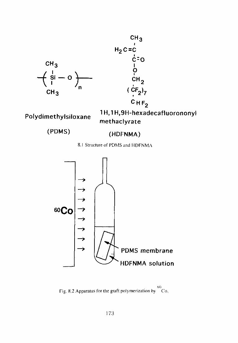
CH3
ロ H2C=C
6・o
CH 3 1
層 CHF2
1H,1H,9H-hexadecafluorononylPolydimethylsiloxane methaclyrate
(PDMS) (HDFNMA)
8.lStructure of PDMS and HDFNMA
→
→
→
60Co→ →
→
→
→ PDMS membrane
HDFNMA solution
6o Fig.8.2 ApParatus for the graft potymerization by Co.
173
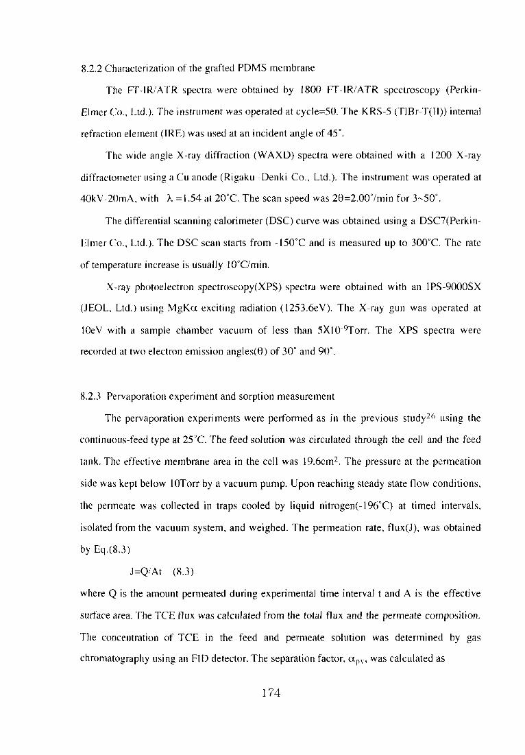
8.2.2Characterization of the grafted PDMS membrane
The FT-IRIATR spectra were obtained by 1800 FT-IRIATR spectroscopy(Perkln.
日mer Co., Ltd,). The instrument was operated at cyde=50. The KRS-5(TjBr-T(ID)internal
refraction element(IRE)was used at an incident angle of45°.
The wide angle X-ray diffraction(WAXD)spectra were obtained with a且200 X-ray
diffractometer using a Cu anode(Rigaku-Denki Co., Ltd.). The instrument was operated at
40kV.20mA,with λ=1.54 at 20℃. The scan speed was 2θ=2.00°/min for 3~50°.
The differential scanning calorimeter(DSC)curve was obtained using a DSC7(Perkin-
Elmer Co.。 Ltd.). The DSC scan starts from」50℃and is measured up to 300℃. The rate
of temperature increase is usually 10℃/min.
Xイay photoelectron spectroscopy(XPS)spectra were obtained with an IPS-9000SX
(JEOL Ltd.)using MgKαexciting radiation(1253.6eV). The X-ray gun was operated at
lOeV with a sample chamber vac肌lm of且ess than 5×10-%「orr. The XPS spectra were
recorded at tw(L)electron emission angles(0)of 30°and 90°.
8.2.3Pervaporation experi ment and sorption measurement
The pervaporation experiments were perfbrmed as in the previous study26 using the
continuotss一琵ed type at 25℃. The feed solution was circulated through the cell and the feed
t壬mk。 The effective membrane area in the cell was 19.6cm2. The pressure at the permeation
side was kept below lOTorr by a vacuum pump. Upon reaching steady state flow conditions,
the permeate was collected in traps cooled by liquid nitrogen(-196℃)at timed illtervals,
isolated from the vacuum system. and weighed. The permeation rate, flux(J), was obtained
by Eq。(8.3)
J=QIAt (8.3)
where Q is the amount permeated during experimental time interval t and A is the effecti ve
surねce area. The TCE flux was calculated from the total flux and the permeate composition.
The concel1重ration of TCE ill the feed and permeate solution was determined by gas
chromatography using an FIDdetector・The separation factor,αP、,was calcu且ated as
174

αp、ニ{Y(1-X)}/{(1-Y)X} (8。4)
wh・・e X and Y d・n・t・the c・ncent・ati…fTCE i・the feed・・d p・m・eat…1・ti・・.
respectively.
Vacuum ↑
A
○
A:cold trap for membrane
B:valve
C:cold trap for collecting samples
Fig.8.3 Apparatus for the composition measurement in the membrane.
175

The dried and weighed membrane was immersed in TCE solution and sealed at 25℃
ulltil equilibrium was reached. The membrane was then taken out of the vessel, wiped
quickly with佃ter paper and weighed. The degree of sorption of TCE soJution illto the
membranes was measured as
Degree of sorption(%)ニ(Wl-W〔〕)/W〔}X l OO(85)
where W()and WI denote the weight of亡he dried membrane and the swollen membrane.
respectively. The concentration of TCE solution soaked in the membrane was determined
using the apparatus inthe schemadc diagram shown in Fig.8.3. The membrane on reaching
equilibrium was taken out of the vesseL wiped quickly with fltter paper and piaced in trap A.
The trap was colmected to the apparatus and quickly cooled by Hquid nitrogen. After the
appal’atus was sufflclendy evacuated, cock B was closed and the TCE so且ution soaked in the
membrane and vaporized by heating with a drier was coElected in cooled traps. The
collcentration〔,f TCE so且ution in the feed and the soaked membrane was determined by gas
chmmatography. The separation factor.α!、was calculated as
αs={Y’(卜X)}/{(1-Y’)X} (8.6)
where X and Y, denote the concentration of TCE in the feed solution and the swollen
membranes. respectivety.
8.3Resuhs and discussion
8.3」Graft poiymerization of fluoroalkyl methacrylate by 60Co source
The effect of irradiation time on the degree of grafting at a fixed HDFNMA content or
irradiation source strength was investigated. Various conditions in simultaneous irradiation
alld the degree of grafting are given ill Table 8.LThe membranes grafted at dose rate of
O.5Mrad/h were brittle and unsuitable for use as membranes. The membranes grafted at dose
ra重es of O.1 Mrad/h were not so brittle. For the PDMS membranes soaked in 300r 100 wt%
HDFNMA and irradiated at O.l Mrad/h、 HDFNMA was grafted equally in the whole
membrane and the grafted PDMS membrane was semipermeable, whHe in 500r 75 wt%, the
membranes were grafted too much and were unsuitable for use as membranes.
176

Table 8」 The degree of grafting under various conditioIls in Siniultaiieous
irradiation
Degree of oraftillo(wt%)
Dose rate of irradiation HDFNMA
(Mrad/h) (wtgo in MeOH)
Irradiat且On tlme(置))
1 2 3 4 5
《」lll1
00000
30
30
50
75
且oo
17.8 699
21.3 98,1 98.4 131
85.1
142
]05 B8
_臨1
220
133 136
46.7
96.6
_」
曽・I
l43
a Grafted too much and unsuitable for use as membranes.
The dependence ofthe degree ofgrafting and membrane thickness()n irradiatlon nllle ls
shown in Fig.8.4. The degree of grafting and membrane thicklless at a fi xed日DFNMA
content and a dose rate of irradiation was increased with increasing irradialioII time. Whell
the irradiation time or irradiation strength increase、 the crosslillking betweell illter-or
intrachains of individual polymers can take place significantly comparedωthe graftillg
reaction. The cross且inking reaction contributes to membrane performance. Whell the
membranes were grafted at a dose rate of I Mrad/h, the crossnnkhlg reaction took place
significantly and the grafted membranes were not swelled in the solvellt In this study, the
effect of irradiation time and HDFNMA content on the crosslinking reaction and gr託lfting
reaciion were investigated. The extent of the crosslinking reactions is a function of the
thickness and HDFNMA composition of a membrane and would be different between
membranes with different membrane thickness or between the grafted PDMS and homo,
poly(HDFNMA)membranes under a given reaction condition. ln this chapter, the
thlcknesses of the membranes before graft-polymerization were constant. and the e仔ect of
the HDFNMA composition was investigated・The homoPolymer・P()且y(HDFNMA)・
P・且ym・・ized・t O.!M・ad/h, w・・diss・1ved in acet・ne・P・ly(HDFNMA)P・ly・・e・ized・f
30wt%HDFNMA was disso且ved in acetone completely, whi】e poly(HDFNMA)Polymerized
of lOOwt% HDFNMA did not dissolve completely and became a geL
177

(1)ののΦ⊂ヱQ一=“
の⊆σ5」ρ⊂⊆Φ⊆」}OO一θ僑匡
(ま峯)2遭・。」20ΦΦ6ΦO
1.8
1.6
1.4
1.2
1
160
120
80
40
00 1 2 3 4
irradiation time(h)
5 6
Fig.8.4 Dependence of the degree of grafting and membrane thickness on
irradlation tinie:(臼)membrane irradiated in 30wt%HDFNMA at O.5Mrad/h,(0)
in 30wt%at O, I Mrad/h,(△)in 100wt%at O,1Mrad/h,(◇)in MeOH at
O.1Mrad/h.
178

1.5
1.4
↑ 1.3)歪
1.2
1.1
1
0 1 2 3 4 5
1rradiation time(h)
Fig.8.5 Dependence of viscosity of poly(HDFNMA)oll irradiation time.
6
179

Poly(HDFNMA)polymerized of 100wt% HDFNMA was crosslinked. because the
HDFNMA colltent was high and the density of the radicals produced by irradiation was high.
The results show that the grafted HDFNMA of lOOwt%HDFNMA was crosslinked. The
poly(HDFNMA)made‘)f 30wt%HDFNMA by irradiatlon was viscous and dissolved ln
acetone completely. The grafted HDFNMA of 30wt%HDFNMA was not crosslinked. The
relative viscosity of poly(HDFNMA)polymerized of 30wt%HDFNMA at O.1Mrad/h as a
func重loll of the irradiatlon time is shown in Fig.8.5. The viscosity was increased with
irradiatioll tilne. The results showed that the degree of polymerization was increased with
irradiatiOII tinle.
8.3.2 Characterization of the grafted PDMS membrane
The FT-IRIATR of the grafted PDMS membranes is shown in Fig.8.6. After the
PDMS was grafted with HDFNMA, a characteristic new peak was observed near H50 alld
740cmrl. Theρeaks are characteristic peaks ofρoly(HDFNMA), The intensity of these
peaks was increased with the grafted amount。
Fig.8.7 shows the WAXD patterns of the grafted PDMS membrane, As reported by
Nakamae54,重he lower 2θof the inner ha】o is assigned to the intersegmental distance of the
po[ymer, and the Iarger 200f the otiter halo is assigned to the intrasegmental distance of the
polymer. The halo for PDMS was observed at 20ニ12°and 21°.The halo for poly(HDFNMA)
was observed at 20=17°and 40°. Intersegmental and intrasegmental distances of
poly(HDFNMA)were narrower than those for PDMS. For the grafted membrane、
20=且7°and 40°values of the halo were observed in addition to 20=12°and 21°for PDMS、
and the lntensity of the ha且o for po且y(HDFNMA)increased with increasing degree of
grafting、 Furthermore. no new haio was observed fbr the grafted PDMS membranes. PDMS
and poly(HDFNMA)existed indMdually in the grafted PDMS membranes, The
semipermeable grafted PDMS membrane is considered to have a microphase-separated
stru ctuIre. i。e.、 a separated structロre of PDMS and grafted HDFNMA54. PDMS is a rubbery
polymer and it clearly has no crystalline strt且cture based on the diffraction patterns.
180

(a)
\」
i:
(b)
1
、「 }1
1(c)
1
1600 1200 800 400(cm-1)
Fig 8.6 FT-IRIATR spectra of PDMS membranes before and af重er graft
polymerization of HDFNMA:(a)membrane irradiated at O. 1 Mrad/h for 5h il】
1 OOwt (Z HDFNMA,(b)for lhil130vv,t‘?i HDFNM〈:‘c)PDMS.
181

5 10 15 20 25 2θ
30(°)
35 40 45
Fig,&7“/ide angle X-「ay diffractioll p壬、ttems of PDMS alld gratlted PDMS
membranes:(a)111embrane irradiated il130wt(7,・HDFNMAat O」Mrad/h for 5h、
(b)for 3h、(c)lbr lh;(d)PDMS;(e)poly(HDFNMA).
182

From the diffraction patterns of the regioll of poly(HDFNMA),:10 crysta川11e stl’ucture was
observed ill the membrane・ln the separation processes ill nonρorous nlenlbranes, it has been
found that both sorption and diffusion depend ol1 lhe degree of crystallization. Gas alld liquid
can permeate the amorphous regiolls preferentially compared with the crystal l℃gi〔川s55.
Furthermore, the intersegmental and illtraseglllental distances of tl】e polymer alst)affecuIle
penneability4.
The DSC curves of the grafted PDMS membralles are sllown iEl Fig.8.8, Fo口he
membrane after grafting with HDFNMA, the elldothermic peak of the internal friction energy
between the macromolecular chains for PDMS was observed at-124℃. The peak for由c
homopolymer of HDFNMA polymerized by irradiatioll was Ilot observed ill the rallge of
-150°C~300°C Fig89 shows the corre且ation between the internal fric(ion energy fOl’{11e
macromolecular chains(J/g)at-124℃and the degree〔,f grafting f(⊃r the grafted PDMS
membranes. The internal friction energy between匡nolecular chaitis(」/g)for the graf1ed
PDMS membranes was decreased with increasing degree of grafting. The peak of¢he intern託il
friction energy between the macromolecular chains(J/.g)for the grafted PDMS membralles
was obtalned at the same temperature for PDMS;hellce. it is considered that the gralled
PDMS membralles have the microphase-separated structure of PDMS alld grafted
HDFNMA56. The linear rdationship between the hlterllal friction energy between
macromolecular chains(J/g)alld the degree of graftil】g is better for membralles soaked ill 100
wt%HDFNMA and irradiated at O」Mrad/h. Becatlse the qLiantity of PDMS ill a ullit
vdume of the grafted PDMS membralles which was soaked ill l(X)wt%HDFNMA{md
irradiated at O」Mrad/h is constant、 the intet’nal fricli()ll energy betweell macromolecular
chainsforthe membranes irradiated in l〔X)wt「7c HDFN, MA was in inverse prop〔)rtion lo the
degree of graftillg, The p()ly(HDFNMA)regions iEl lhe tneinbranes soake(l il日00 wt%
HDFNMA alld irradiated al O.1Mradlh were disperse(1 quite homoge置】eously.
The surface morphoi()gies of the grafted PDMS membralles were analyzed by XPS
spectra. The XPS spedra are shown in Fig.8.10. By gl『aftiπ1g with卜IDFNMA,the fhK)rine
18;
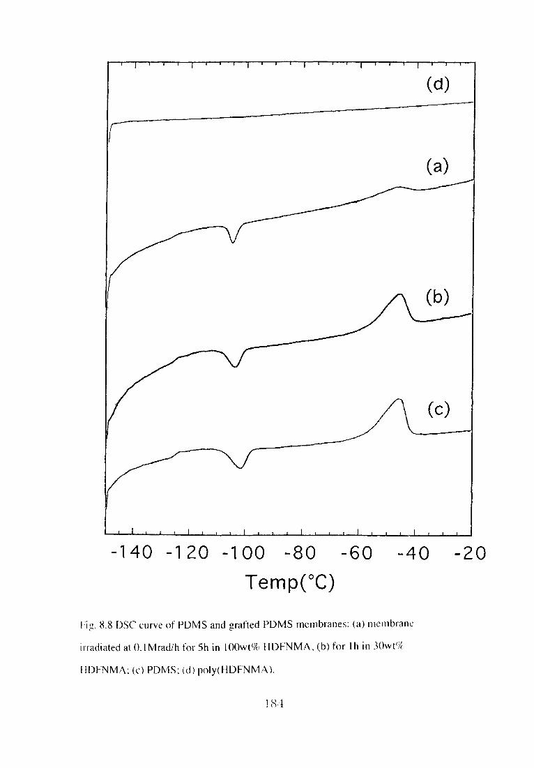
一140 -120 -100 一80 一60 一40 一20
Temp(°C)
卜i・8.8DSC curve of l)DMSand orafted PDMS membralles:(a)nieinbranc ∂ Lh°
il’radiated atO」Mrad/h for 5h in lOOwt%HDFNMA、(b)for lhin 30wt%・
HDFNMA:(c)PDMS:(d)pdy(HDFNMA).
184

(①
_「)>O」Φ⊂Φ⊂oP2と一僑⊂」Φ“≦
20
15
10
5
0
0 50 100
、O
Q
150
Degree of grafting(wt%)
Fig.89 Dependence of the interllal friction energy between molecul壬lr chains on
the degree of grafting of the grafted PDMS membranes:(□)membranc irradiated
in30wt%HDFNMA at O5Mrad/h,◎in30wt%at O.IMrad/h,(○)ill lOOwt‘%at
O.IMrad/h.
185

700 690 680300 290 Binding energy(eV)
280
Fig.8」OXPS spectra of PDMS alld grafted PDMS membranes:(a)membralle
irradlated il)1(X)w t e7(HDFNMA at O. i Mrad/h f(、r 511.(b)for 3h.(c)f⊂)r lh:(d)
PDMS、
186

Table 8.2 Fluorine to silicon. oxygen to silicoll and carbon to Silicon atomic
ratios for the surface of PDMS andσrafted PDMS membranes b XPS Anal sis
HDFNMA
in MeOH
(svle/,)
lrradiation
time(h)‘L
F.lect「(、n
emlSS且on
oangle( )
Atomic rutiob
F/si O/Si C/si ト〆Si calCLda吐ed
b}dc .9 r¢c
orL, r211’t i 11 L,
【00 1 30 2.71 t.一“ 2.82 2,50
90 L61 1.5〔} 2.72
1(X) 3 30 3.29 1.40 2.96 3.15
90 3.50 L59 321
1〔X) 5 30 5.54 L41 3.6量 3.39
90 6.62 1.83 4.07
0 5 30 -L’ 1,19 1.75
90 _ぐ 1.37 1.85
PDMS 90 L’ L↓↓ 1.87
a:Dose ratc oll irradiatk〕n:O」Mrad/h.
b:F/Si:Flu(,rine atomic ratio(%)ノSilicon a【()mic rati〔〕(‘め.
0/SjlOx)gcn a!omlc ra1ioα)ノSilic‘)n atomicralio(t7()。
CISi:Carboll atomic ratio((7()/S田con atomic raIi()(‘/, }.
c:Not detected.
atom was detected and the blnding energy shift associated with the structure of
fluorinated(CF, CF2)and carbonyl(Cニ0)carbon species was shown57・58. The ratios of
月uorine, oxygen, carbon, and silicon atoms were analyzed and calculated for a few nm
beneath the surface on the grafted PDMS membrane at 30°and 90° 垂?盾狽盾?撃?モ狽窒盾氏@emission
angles and are characterized inTable 8。2. ln these spectra, the coMpositioll of the atoms was
determined up to 4.5 and gnm deep below the su rface at photoelectron emission angies of
30°and 90°, respectively59. The ratios of fluorine and carbon on the grafted PDMS
membranes were increased due to the introduction of HDFNMA by irradiation. The degree
of grafting of the membrane, soaked in 100 wt%HDFNMA and irradiated at dose rates of l
Mrad/hr for 5h、 was l43wt%、 and the thickness increased abo山1,3 times, According to the
observation of silicon atoms on the grafted PDMS membrane surface, it is considered that the
187

pdy(HDFNMA)domains were dispersed in the enti re PDMS membrane homogeneously by
irradiation.
The degree of grafting of the grafted PDMS membrane was more than lOOwt%, while
the degree of sorption of HDFNMA into PDMS membrane was l 3wt%. As a result, the
following is considered・Firs口he graft polymerization starts with one region in the PDMS
membrane. HDFNMA was then grafted more frequently on the poly(HDFNMA)domain
than the PDMS domain due to the afflnity of HDFNMA for poiy(HDFNMA). The grafting
on the poly(HDFNMA)region was promoted to extend the volume of PDMS, and, in turn,
the grafted PDMS membrane had a microphase-separated structure.
The ratio of the fluorine atom at 30°was almost the same as that at 90°on the su rface
of the membrane, The ratio of the fl uori ne atom by the XPS spectra corresponded to that
calcu且ated by the degree of grafting. For the structure of the grafted PDMS membrane, a
layer〔}f poly(HDFNMA)was not fbrmed on the su rface of the PDMS membrane. The
poly(HDFNMA)domains were dispersed into the entire PDMS membrane homogeneously
by irradiati()n.
The domains of poly(HDFNMA)in the grafted PDMS membranes had a particle size
which sca賃ered natural light, and the domains were dispersed homogeneously as expected,
8・3,3Pervaporation fbr grafted membrane
Fig,8」lshows the effect of the}rradiation time on the flux and the separation factor
for TCE soiution in pervaporation through a PDMS membrane irradiated in MeOH. The
pervaporation of a PDMS membrane irradiated in MeOH was substantialty affected by
irradiation. The effect of irradiation on the permeability of the PDMS membrane to gases was
investigated by M。 Mi!10ura et aL60. The reslIlts suggested that no remarkable difference
except fbr crosslinking ill the chemical structure between the unirradlated samples and
irradiated salnples could be seen, but the effects of irradiation on the transport of gases
through the PDMS membranes were negligibly small.
In this chapter of pervaporation through irradiated PDMS. almost the same results were
188

obtailled.
Fig.8」2shows the effect of the irradiation time on the nux and the separatioll facωr for TCE
solution in pervaporation through a PDMS membrane irradiated il130 and IOOwt%
HDFNMAIMeOH. The flux of the grafted PDMS h130wt%HDFNMA membranes was
increased with increasing irradiation time. and the separation f註ct(、r was decreased with
illcreasing irradiation time. The degree of grafting and membrane thicklless was illcreased by
irradiation. The poly(HDFNMA)region was increased段nd growll by graft po且ytnerizatic)n to
extend the vo且ume of PDMS so that the伽x ofthe grafted PDMS membralles was increa: ed.
The flUX Of the PDMS membrane grafted PDMS ill lOOWt%HDFNMA WaS COIIStallt With
increasing irradiation time, and the separation facωr was increased with illcreasillg irradiatioll
time. By measurents of the ATR spectra of the grafted PDMS membranes. no chal亀acteristic
peak of crosslinking betweell inter-or intrachains of individual polymers was observed.
However, the homo-poly(HDFNMA), polymerized of 100wt‘%HDFNMA at O. i Mrad/h.
was not dissolved in the sol vent and became a gel.The crossljnking reactions a量Yect b(》tll the
sorption and permeation behavior. The more the crosslinkiIlg occurs, the less the permcまinls
are sorbed into the membrane and the slower they permeate through the membrane. r「he刊ux
ofthe membranes grafted and crosslinked in lOOwt%HDFNMA was 1(》wer than that of the
membranes grafted in 30wt%. The grafted amount, the degree of crosslinkillg alld the
permselectivity of the membrane grafted in且00wt%HDFNMA was increased with
increasing irradiation time.
The flux as a function of the TCE concentration in the feed solution ls shown in
Fig.8.13. For the PDMS and the membranes irradiated in MeOH. the f1 tix was alm()st
constant with increasing feed concentration. For the membranes grafted with HDFNMA, the
flux was decreased with feed concentration. The water nux and TCE flux as a function of
the TCE concentration in the feed solution are shown in Fig.8.14 for the grafted PDMS
membranes. For the PDMS membrane irradiated in 100wtで70 HDFNMA for l h, the water
flux was almost constant with increaslng feed collcentration, alld for the more grafted PDMS
189

(£箪」」\①メ)×コ一L
(-)」BQ澱⊆ε。。」8Φりり
0.15
0.1
0.05
0
2500
2000
1500
1000
500
0
0 1 2 3 4
1rradiation time(h)
5 6
Fig.8」且Effect of irradiation time on the flux and separation factor(αp、)ofTCE-
water mixtures in pervaporation through irradiated PDMS membrane at 25℃:(口)
O,o ( wt%feed concentration;(◇)0.025wt%.
190

(=N∈\9×⊇」
0.15
0.1
0.05
0
2500
↑)20006一Q£こ£邸」8Φ゜つ
1500
1000
500
00 1 2 3 4
1rradiation time(h)
5 6
Fig・8」2E仔ect・f irradi・ti・n tim…th・flux and・ep・・ati・・fact・・(α,、・)・fTCE-
water mixtures in pervaporation through grafted PDMS membranes at 25℃:(○)
0.025wt%feed concentration through membrane irradiated at O」Mrad/h in
30wt%HDFNMA,(△)0.025wt%feed concentration through membrane
irradiated at O. I Mrad/h in 100wt%HDFNMA.
191

0.15
じつ
α の
0
(=N∈\9)×⊇」
0
0 0.Ol 0.02 0.03 0.04
TCE in feed(wto/o)
Fig,8.13Effect offeed concentration on flux for TCE-water mixtures in
pervapora口on through grafted PDMS membranes at 25℃:(○)membrane
irradiated in lOOwt%HDFNMA at O. IMrad/h for 5h,(◇)in MeOH at O.IMrad/h
fc)r5h;([])PDMS,
192

0.04
2N O.03∈
\oM)0.02 cil
80.01ト
0
0.15
」0
(=N∈\9)
500
×⊇}」Φθ僑
0
0 0.01 0.02 0.03
TCE in feed(wt%)
0.04
Fig.8.14Effect of feed concentration on flux for TCE-water mixtures in
pervaporation through grafted PDMS membranes at 25℃:(○)membrane
irradiated in lOOwt%HDFNMA at O.1Mrad/h for l h;(◇)for 3h;(口)for 5h.
193

membrane、 especially that irradiated in lOOwt%HDFNMA for 5h, the water flux was st田
further decreased with increasing feed concentration. For all the membranes, the TCE f畳ux
was increased with increasing feed concentration, and especially fbr the membrane irradiated
i旧00wt%HDFNMA for 5h, the tendency was significant.
In chapter 3. for the membranes modified using HDFNMA by UV irradiation, the flux
was decreased with increasing feed concentration. Due to the introduction ofthe hydrophobic
polymer, HDFNMA, the TCE quantity sorbed into the membrane was so high that the
diffusion of water was prevented; in turn, the f且ux was decreased. ln this chapter, simi且ar
phenomena were observed.
The relationships between the TCE concentration in the feed and permeate are shown in
Fig.8」5, For all the membranes, the TCE concentration ill the permeate was increased with
increasillg feed c(mcentration, and especialty when the membranes was irradiated in 100wt%
HDFNMA fbr 5h. the increase was significant。
The separation factor,()tpY as a function of the TCE concentration in the feed so置utiOtl is
shown in Fig.8.16.(xp、、 was increased significantly with increasing feed concentration for
the membralle irradiated in IOOwt%HDFNMA for 5h. In the grafted PDMS membrane、 the
best separati()n performance was shown due to the introduction of the hydrophobic poly置ner,
poly(HDFNMA).
8.3.4Pervaporation for poly(fluoroalkyl methacrylate)membrane
The sotutioll of poly(HDFNMA), a homopolymer pGlymerized at 30wt%at
O.1Mrad/h for 5h, was cast. The membrane of po置y(HDFNMA)polymerized for sh、 a
membralle with a thickness of 270μm, was used for pervaporation. The flux as a function of
~he TCE concentration in the fbed solution is shown in Fig.8.17. The total and water flux
were almost constant with increasing feed concentration. TCE flux was increased with
mcreaslng feed concentration、 and the rate was restrained at high feed concentration.
194

40
30
20
10
(ま隻)Φ罵Φ∈」ΦΩ⊂口Qト
0
0 0.01 0.02 0.03 0.04
TCE in feed(wt%)
Fig.8.15Relationship between TCE concentration infeed and permeation in
pervaporation through grafted PDMS membranes at 25℃:(○)metnbrarie
irradiated in lOOwt%HDFNMA at O」Mrad/h for 5h,(◇)in MeOH at O. l Mrad/h
for 5h;([])PDMS.
195

2500
0002
0051
0001
(-)」8Qσ。芝£僑」巴Φしり
500
0
0 0.01 O.02 0.03 O.04
TCE in feed(wto/o)
Fig・8」6Effect・f feed・・ncent・ati・・…ep・・ati・・fact・・(α,,)i・p・・vap・・ati・・
through grafted PDMS membranes at 25℃:(◇)membrane irradiated in 100wt%
HDFNMA at O」Mrad/h for 5h,(○)in MeOH at O. iMrad/h for 5h;(口)PDMS.
196

0.004
0.003
εミ90・002支i
O.001
0
0 0.01 0.02 0.03
810-5
61 O’5
410-5
210-5
0
O.04
(‘N∈\①X)×⊃弔]Oト
TCE in feed(wt%)
Fig.8.17Effect of feed concentration on flux for TCE--water mixtures in
pervaporation through poly(HDFNMA)membranes at 25℃:([])total flux;
(○)water刊ux;(△)TCE flux.
ユ97
The thickness of the poly(HDFNMA)membrane was 270μm, around fi ve times as thick as
grafted PDMS and PDMS membranes. The volume of the flux through the poly(HDFNMA)
membrane was one to thirty~ninety times the volume of the flux through the grafted PDMS
and PDMS membranes. The flux was inversely proportional to the membrane thickness61」t
is predicted lhat the flux of the poly(HDFNMA)membrane is one fifth of the flux through
重he grafted PDMS and PDMS membranes, if the poly(HDFNMA)membrane had the same
permeability as the grafted PDMS membranes. As we mentioned in the previous reportはhe
inters egmental and intrasegmental distances in poly(HDFNMA)were narrower than those ill
PDMS. Hence. it is collsidered that the diffusion of the permeates was decreased and a Iow
tl ttx was obtained for the poly(HDFNMA).
The diffusivity of TCE Ino且ecules must be much lower than that of water due to the
larger molecular size of TCE. ln the po】y(HDFNMA)with Iow permeability to permeates、
the TCE-permeselectivity was restrained.
Miyata et al .: i ・22reported the characteristics of permeation and separation for aqueous
ethanol soluti(、11s through methy且methacrylate(MMA)dimethylsiloxane(DMS)copolymer
membranes wilh置nicrophase-separation. They mentioned that, due to the high solubility and
good diffusivity of ethanol molecロles in the PDMS phase of the rubber state, the PDMS
phase transports ethanol betterthan water.
Furthermore, the mass transport takes p塵ace solely in the amorphous polymer phase,
nol at all in the crystalline phase, and on且y part of the interface area is avaHable for
perineation in the seini-crysta11ine phases55. The grafted PDMS membrane had a microphase-
separaled s tru cture, i.e.. a separated structure of PDMS and graft-polymerized HDFNMA.
The permselectivity ofTCE was high、 due to the introduction of the hydrophobic polymer,
poty(HDFNMA). The permeation mechanism for the grafted PDMS membranes is shown in
Fig.6.18. For the pervaporation performance of the HDFNMA-grafted PDMS membrane,
the foHowing wag. cong. idered. The permeability of the PDMS phase was significantly great
198

Feed solution
Permeate
[コ:PDMS, (璽夢:Grafted poly(HDFNMA)
Fig.8.18Tentative川ustrati()n of the permeati()n through the gu・afIed PD~1.S
membralle for TCE-water mixture.
199

100
75
50
25
(ま妄)Φ器」O∈Φ∈三山Oト
0
0 0.02 0.04 0.06 0.08 0.1 0.12
TCE in feed(wt%)
Fig.8.19 Sorption of TCE on grafted PDMS membranes as a function of the feed
concentra重ion at equi量ibrium:(◇)membrane irradiated in 100wt%HDFNMA at
O.IMrad/h for 5h;(O)in MeOH at O, I Mrad/h for 5h;()く)PDMS 50μm;(口)PDMS
200pt m.
200

alld that of the poly(HDFNMA)phase was too Iow to affecUhe total peEll、eatioll directly.
However, in the permeation at the interface of poly(HDFNMA)and PDMS, it playedとm
important ro且e inthat poly(HDFNMA)had a much stronger affinity for TCE than for water.
8.35Sorption and diffusion of the membrane with phase separation structure
The isotherms of sorption for grafted PDMS membranes are presellted ill Fig.8」9.
Below lwt%TCE solution, the degree of swelling of the PDMS membralle with a thicklless
of 50μm was less than lwt%, too small a quantity of solution ill the membrane to determii)e
the composition, Hence, a PDMS membrane with a thickness of 2001t m was used in this
sorption measurement. For the PDMS membrane irradiated i[1 MeOH and PDMS. straight
lines can be fited to the sorption isotherms. For the grafted PDMS membranes, the
concentration of TCB solution soaked in the membrane was increased significε1ntly with
increasing feed concentration. It is effective for TCE sorption into the membralle to
introduce the hydrophobic polymer, poly(HDFNMA). The membrane that had a high
sorption selectivity for TCE showed great separation performance.
Table 8.3 Sorption and pervaporation data for PDMS and grafted PDMS membralle
Mernbranc TCEin feed
(wt9/r’)
Sorption data
TCE Scparation TCE
in membrane faclor infccd
(wt%) (αs) (wtr/()
Pen『ap(,rati()n data
TCE Scpa「ttti(m Scpara1ion
in mCmbrane ゼact〔〕r t’ac【or
(、、t(/‘) (α}」 ‘αDl
Pl)MS irradiatcd
in HDFNMA lOOwt%
at O. 1 Mrad f〔,r 5h
PDMS
O.Oi23
0.0280
O.0131
0.0282
919
904
6.90
13.2
2010
2470
564
538
〔〕.0104
0.〔〕265
{},OIO2
0.0263
6.63
37A
4.83
9,55
684
2250
496
402
o.34〔l
O.912
0.879
0.747
201

The relationship between the separation factor in permeation(αP・・)・the separation
factor in sorption(αs), and the apParent separation factor in di ffusion (αD) is given by
Eq.(8.7).
(」LPN=αs・αD (8・7)
αDcan be described in Eq。(8.8)using Eq.(8.4)and(8.6).
αD={Y(卜Yl)}/{(1-Y)Y’} (8.8)
where Y and Y’denote the concentration of TCE in the permeate solution and the swoHen
meinbranes under the salne feed solution, respectively.
αpい(Ls,(tD are sh〔)wn in Tab且e 8.3.α1)values calculated by Eq.(8.8)using the sorption
isotherms in Fig.8.19 and the pervaporation in Fig.8.15 as a function of the TCE
concelltration hl the feed sdution are shown in Fig.8.20. The resu且ts show thatαD of the
grafted PDMS membrane was significantly increased with increasing feed concentration.
Frhe permeation of TCE and water molecules in pervaporation through the grafted
PDMS membranes is concluded to be the following;The mass transport takes place
signmc日11tly in the PDMS phase. At the interface of poly(HDFNMA)and PDMS, a high
solubility performance of TCE molecules was shown. At a low feed concentration of TCE
solution. the di仔usivity ofTCE molecules must be much lower than that of water due to the
且arger molecular size ofTCE. At a high concentration ofTCE solution, TCE was sufficiently
sorbed into the membrane. The diffusion of water was prevented by the TCE molecu且es, and
ill turn, the permeselectivity ofTCE was significantly increased。
In this chapter, the PDMS membranes were improved with graft polymerization of
HDFNMA by simultalleous irradiation method. The permeability of the PDMS phase was
significalltly great and that of the poly(HDFNMA)phase was too low to affect the whole
permeation of the grafted PDMS membrane directly. However, in the permeation, at the
interface of poly(HDFNMA)and PDMS、 poly(HDFNMA)showed excellent solubmty
performance for TCE. In order to enhance the selectMty of a rubber poiymer membrane
202

(-)」B8芒εΩ巴Φ゜り
1
0.8
0.6
0.4
0.2
0
0 0.01 0.02 0.03 0.04
TCE in feed(wto/o)
Fig.8。20 Effect of feed concentration on the separation factor((L D)in
pervaporation through PDMS and grafted PDMS membrane at 25℃:(一)
membrane irradiated in lOOwt%HDFNMA at O」Mrad/h for 5h;(_)PDMS.
203

which has a high permeability、 such as PDMSjt is effective to introduce a material which
has a high solubility・
8.4Conclusions
ln this chapter, we improved the PDMS membrane with graft polymerization of
HDFNMA, which has the e冊ect of increasing the selectMty for chlorinated hydrocarbons.
by a 60Co source and characterized the grafted PDMS membrane. Simultaneous irradiation
is a method ill which that monomer and polymer are irradiated simu且taneously. In this
chapter、 siinultaneous irradiation was studied, The grafted amount by simultaneous
irradiation was rich. Therefore、 the permeation behavior was differ from rubbery untreated
PDMS membrane and the litt畳e grafted PDMS membrane by preirradiation in previous
chapters.
The grafted PDMS membranes had a microphase-separated structure, i.e., a separated
struct”re of PDMS and grafted HDFNMA. For the graft polymerization, the following is
considered. First, the graft polymerization starts with one region in the PDMS membrane.
More HDFNMA was then grafted oll the poly(HDFNMA)domain than the PDMS domain
clue to tlle affinity of HDFNMA for poly(HDFNMA). The grafting on the
poly(HDFNMA)region was promoted to extend the volume of PDMS, andjn turn. the
grafted PDMS membrane has a microphase-separated structure. The poly(HDFNMA)
domains were dispersed into the entire PDMS membrane homogeneously by irradiation. For
the membranes soaked in lOO wt%HDFNMA and irradiated at O.1Mrad/h, the
poly(HDFNMA)domains were dispersed quite homogeneously.
In the grafted PDMS membralles, the best separation performance was shown with the
introduction of the hydrophobic polymer, poly(HDFNMA). The concentration of TCE
sorbed il)to the membrane was high. due to the introduction of the hydrophobic polymer,
poly(HDFNMA), The membrane that had a high solubility g. electivity for TCE showed great
separation performance. The permeability of the PDMS phase was significantly great and that
of the poly(HDFNMA)phase was too置ow to affect the whole permeation of the graf【ed
204

PDMS membrane directly. However, poly(HDFNMA)h盈d a much stronger壬1ffinity for TCE
than for water. Thefore, the permeab川ty and permeselectivity of TCE on the surface of
poly(HDFNMA)and PDMS are high, and the permeation on the surface playe出mpく)1てallt
role inthe permeation through the grafted PDMS membrane. At a low feed concentra電ion of
TCE solution. the diffusivity ofTCE mo且ecules must be much lower than thaωf wate1’dしle to
the larger mdec田ar size of TCE. At a high concentration of TCE soluti⊂)11. TCE was
sufficiently sorbed into the membrane、 so that the diffusion of water was prevented by the
TCE molecules;in turn. the permselectivity ofTCE was illcreased significantly.
The permeation behavior of the grafted membranes which have high grafted amoullt
and phase-separated structure in composite with PDMS and poly(HDFNMA)was differ
from rubbery untreated PDMS membrane and the litde grafted PDMS membralle by
preirradiation. Not only solute properties and interaction but also membralle stl’uctul’e
effected on the permeation behavior.
85Acknowledgments
The authors are grateful to Fuji Systems Corporation for providing tlle PDMS
membranes. Gratefui acknowledgment is also made to Dr. Masaharu Asano of the Japan
Atomic Energy Research Institute for his kind permission and helpfu且discussion otl the
irradiation by 60Co。
8,6Ref巳rence
l)S.Yamahara, S. Nakao,ルlaku (〃le〃zbraneノ,18,69(1993),
2)T.Yamagutl, S。 Nakao、 Kagaku-koblgyo(Che〃~~(‘a〃’~du.ぎ1左vノ,47,51d996).
3)M.G. Liu, J.M. Dickson, P, Cote,ノ.Men~hr, S(・i.,111,227(1996).
4)T.Nakagawa, A. Kanemasa, Sen ’i Gakkaishi,51,】23(1995),
5)C.Dotremont, B. Brabants, K. Geeroms, J. Mewis, C. VandecaSteele,ノ.Me,nわr.5’‘ゾ.,
104,109(1995).
6)C.Visvanathan, B。 Basu, J.C Mora,1nd. Eng. Chem, Res。,34,3956 d 995).
205

7)S.B. McCray, D.T. Friesen. D.D. Newbold. R. Ray, D⊥. Millard, Pr(ノぐ7〃11’lt Co’ゲ
Pervaporatiθn 1)ro(ぞ∬ぐhem. lnd.ノ995,422 d 995).
8)D.Yang. S. Majumdar. S. Kovenklioglu、 K.K。 Slrkar,ノ.ルfe〃ihr.∫で・~.,103,195
(1995).
9)K.Ogasawara, T. Masuoka. T. lwatsubo. K. Mizogichi, Ground warter,37,47(1995),
直O)J,Schauer、ノApρl P‘Jlv〃~Sci.,53,425(1994).
11)C.Dotremollt, S.V.D. Ende, H. Vandommele, C. Vandecasteele, Desalinution,95、91
(1994).
12)PJ. Hickey. C.H。 Gooding,ノ.ルfe〃ihr, LS)c i.,88,47(1994).
13)P.J. Hickey、C.H. Goodin9,.ノ.ルle〃ibr。 Sci.。97,53(1994).
14)T.Yaaguchi,S, Yamahara, S. Nakao, S. Kimura,ノ.ル1emhr. Scii.,95,39(1994).
15)s.Goethaert、 c. Dotremont, M, Kuijpers, M. Michels, c. vandecasteele,ノ,ルle’nhr.
、~i‘ゾ.,78、135(1993).
16)B.K. Sri nivas, M.M. El-Halwagi, Co’npLtters Chem. Engn8.,17、957(1993).
17)A.R.J. Andrews。 A. Zlatkis, M.T. Tallg, W. Zhang, H. Shallfield, Envirθn.∫(・’.
71e(・h〃θ1..27.lI39(1193).
且8)M。L. Jacobs. R.W. Baker、 J. Kaschemekat, V.L, Simmolls, Proc A WMA Annuハ4eet、
86,1(且993).
19)M。Hoshi、T. Saito, A. Higuti,T. Nakagawa, Sen ’i Gakkaishi,47,644(1991).
20)T.Nakagawa.ルfctkti(me〃ibrane,.20,且56(1995).
2DM・Nakamura, S.Samejima, T. Kawasak転ノ.ルfembr. Sci.,36,343(1988).
22)T,Miyata、 Y.Nakanishi, T. Uragami, P‘,1.wmer Preprints,ノaρan.45,1970(1996).
23)L・Bohn, Rtthber Che’η. Te(・hnol.,41,495(1968).
24)S.Okamoto,ルlakLt(tne〃~わrane♪,14,277(1989).
25)A.Charlesby, Atomic radiation and polymers, Pergamon press Ltd.. England,(1960).
26)GOdian. R. Henry, R. Koenig. D. mangaraj, L.D, Trung, B, Chao, A. Derman,ノ.
1)θ lv〃~.∫(ゾ.ρぐ,1y〃~.(・he〃~. Ed.,13.623(1975).
27)T・Yasukawa、 Y. Sasaki、 K. Murakakami.ノ. Pで小〃z.∫cψ‘小’n. Physics Ed., B,17
206

d975).
28)LIshigaki、 D.J. Lyman,ノ. Me〃zわr.∫d.. L 301(1976).
29)S.Yamakawa, F. Yamamoto, Y、 K飢o, Macromo】.,9,754(且976).
30)H.Yamakita, K. Hayakawa,ノ. Poly〃1. S(・i.ρθ~η.(・he’η. Ed.,14.1175 d 976).
31)A.Rabie, G.odian,ノ.1)‘,1y〃~. S(・’.ρ‘♪1y〃~.(’he’η. Ed.、15,469(1977).
32)A.Rable, G. odian,ノ. P‘,4v’71. Sci. polv〃~.(・he〃1. Ed.、15,1619(1977).
33)M.Imai,ノ. Poly’n. Sci.ρで小m. che’η. Ed.,16,1539(1978).
34)EYamamoto, S. Yamakawa、 Yoshinori kato,ノ. Pθへ・’11. S(・i.1)θ1.v〃,.〔・11e〃~, E‘ノ.,16、
1883(1978).
35)F.Yamamoto, S. Yamakawa, Y. kato,ノ.1)01y〃z. S(・i、1フ‘♪1y’η. che’η. Ed.t 16,1897
(ig78).
36)EYamamoto, S。 Yamakawa,ノ. P‘,4yni.∫d.!πoly川, P1ハ・∫’(・.sだゴ..17,且581(1979).
37)GOdian, A, Derman, A.H. Zahran, J. Tsay,ノ.1)θlwm.∫(・1。ρθ1y〃’.(・ノle〃~. E【ノ,,17,
2645(1979),
38)E.A, Hegazy, N. E卜Assy, A. Rabie, L 1shigaki,J. Okamoto、ノ.1)θls・ii~. S‘・1.ρθハ・〃L
(・hem. E{ム,22,597(1984).
39)GOdian, D. Lee, V. Pate1,A. Rabie, A.H. Zahran,ノ,、POIwm.5‘・’. pθ4vn~.{ゾle〃1. E(ノ.,
22,769(1984),
40)T.Sasuga, N. Hayakawa, K. Yoshida,ノ. i)ol.ym.∫cムρ01}・m.1)毎,∫~c∫Ed.,22,529
(1984).
41)K.Saito, S.Yamada, S. Fukusakl,T. Sugo、 J. OkamoIo,ノ。ルdemhr.5(・i.,34,307
(1987).
42)K.Saito, T. Kada, H. Yamaguchi, S. Fukusaki,T. Sugo, J.Okamoto,ノ.ル1emhr。 S(・i.,
43、13且(1989).
43)K.Saito, T. Yamaguchi,T. Uezu, S. Fukusaki,T. Sugo, J. Okamoto,ノ.、4/)pl. Pθlym.
∫d.、39,2153(1990).
44)S.Tsuneda, K. Saito, S. Fukusaki,T. Sugo, L Ishigaki,ノ.ルクe〃ihr.5’ci.,7】,1(1992).
45)H.Yamaguchi, K. Saito. S. Fukusaki,T. Sugo、 E Hosoi,J. Okamo給,ノ.ル1embr。 S(・i.,
207

85フ1(1993).
46)W.Lee, K. Saito, H. Mitsuhara, T. Sugo,ノ.ルtemhr. Sci.,81, 295(1993).
47)S.Mishima, T. Nakagawa, Kobunshiノ~θnht{nshu,54,211(1997),
48)N.Kabey, A. Katakai,T. Sugo, H, Egawa,ノ. Aρρ1. Poly’η, Sci.,49,599(1993).
49)D.G. Regand. G.L Gaines Jr., Potym.1)repr., Am. Che,n.∫oc., D’り.1)1wm. Che,n.,
1且,442(1970).
50)Y.Kawakami,T. Aoki, Y. Yamashi瞼、 M. Hirose, A. Ishitani.ル1acromol.,18.580
(1985).
5DX.Chen, J.A. GardellaJr.,ルfa(}ro〃zot.,27,3363(1994).
52)T.Miyata, T. Takagi,T。 Kadota, T. Uragami,M‘・romol. Che〃1. Phvs.,196,12且1
(1995).
53)T.Miyata、 J. Higuthi, H. Okuno, T. Uragami,ノ。 Appt.1)olWm.∫‘ゴ.,61,1315(且996),
54)K.Nakamae, T, Nishino, K. Hara. T. Matsumoto, Kobblnshi Ronhuns/lu,42,2口
(1985).
55)」.G.A. B i tter、 Desa’ination,51,19G984)。
56)W.Wenillg、 R. Hammel、 W.J, Macknight, F.E. Karasz, Ma(γo〃π0!.,9,253(1976).
57)J.D. Ke Roux、 D.R. Pau1, M.F. Arendt, Y. Yuan, L Cabasso,ノ,ルlembr.∫ci.,90,37
d994).
58)M.J.0’keefe、 J.M. Rigsbee,ノ. AppムPoly燗.∫‘ゾ。,53,1631(1994).
59)The society of Polymer Science, Japan, Shin koubしmshi Jikkengaku(experimental
method in po且ymer science voL lO;in Japan, Kyoritsu press Ltd.(1995).
60)M.Minoura. S. Tanj, T. Nakagawa,ノ,、4ppl。 Po/ym. Sci.,22,833(1978).
61)S。Yamada、 K. Hamaya. Kottbunshi Ronhu’zshu,39,407(1982).
208

Chapter 9. Permeation Behavior of Poly(1H,1H,9H・Hexadecafluorononyl
Methacrylate)・fi塁led Poly(1・Trimethylsily1・1-Propyne) Membranes for
Volatile Organic Compound-Water Mixtures
9,lIntroduction
The permselectivity for glassy polymers call be also determiIied by the sorption-
diffusion mechanism like as rubbery po且ymer membrane. The sorption of permeate
component can be controlled by the affinity for the membrane lnateriaL The diffusioll can be
described as the permeatlon rate of component through the rnembrane.
Poly(1-trimethylsilyl-1-propyne)(PMSP)membrane has the highes t permeabi且ity of all
polymeric membranes and its permeation property has been studiedi.B. The permse且ectivity
of volatile organic compounds(VOC)through PMSP was enhanced due to m()ditication o{’
fluoroalky且methacrylate by T. Nakagawa, et. aL3.
ln chapter 8、 polydimethylsiloxane(PDMS)membrane whlch is a rubbery polymer
membrane, was grafted by田,IH,9H-hexadecafluorononyl methacrylate(HDFNMA)using
60Co source and simultaneous irradiation method. ln the pervaporation application of tlle
grafted PDMS membrane, the se且ectivity for trichloroethylene(TCE)was enhanced due to
introduce hydrophobic polymer, poly(HDFNMA)(PHDFNMA). At a high concentration of
TCE solution, the diffusion of water was prevented by TCE moiectlles sorbed in the
membrane, in turl1, the permselectivity ofTCE was increased slgnincant且y.
PMSP is a g且assy polymer and has a lot of microvoidsi.The permseiectivity in PMSP
membrane is controlled by the microvoids and the permeation behavior is different from
rubbery polymer membranes like as PDMS membrane1. ln this chapter, the PMSP
membrane was佃led with PHDFNMA and the sorption-diffusion mechanism in
pervaporation was investigated compared to the grafted PDMS membrane.
9.2.Experimental
9.2.lMembrane preparation
209

PMSP(Shin-etsu Chemical Co., Ltd.)was used throughout this work. HDFNMA
(Daikin Fine Chemical Laboratory Corporation), ethyl butanoate(EBU)(Special grade,W獄ko
Pure Chemical lndustries, Ltd.), and 2-propano((Kanto Chemical Co., lnc.)were used as
received.
The HDFNMA ln ampoules were degassed and sealed ullder vacuum. The ampoules
were irradiated at dose rates of O. l Mrad/h for 5h from a 60Co source at 25℃, After the
jrradiation was fjnished, The obtained polymer, the PHDFNMA was soaked, washed in
acetone and dried under vacuum. The PHDFNMA was ground into a powder by an auto
grinder(Nitto Science Co., Ltd.). and sieved using a JIS 28801 Testing Sieve with a 45
micron aper加re(Tokyo Screen Co., Ltd.).
The PMSP was purified by the solution precipitation method using a toluene-methanol
system. The purified PMSPwas dissolved in toluene to 2.O wt%and cast onto a glass plate.
To the cast sdution was added the sieved PHDFNMA powder and then dried under vacuum.
9.2.2Pervaporation experiment and sorption measurement
The pervaporation experiments were performed as ln a previous study 14““ 1 7 using the
contin lous-feed type at 25°C. The feed solution was circu且ated through the ceH and the feed
tank. The grafted surface of the membrane was kept in contact with the feed solution in the
cell. The effective membrane area in the cell was l9.6 cm2. The pressure on the permeation
side was kept beiow lO Torr by vacuum pumps. Upon reaching steady-state flow.
cond詮ions、 the permeate was collected in traps cooled by liquid nitrogen(-196℃)a重timed
intervals, isolated from the vacuum system, and weighed. The permeation rate of the
solution. the total flux(」), was obtained using eq.9」.
」=Q/At (9.1)
where Q is the amotmt that permeated during the experimental time interval、 t, and A is the
effective surface area, TheεBU and water Hux were calculated from{he total fl ux which is
the permeation rate of the solution(J)and the permeate composition.
The concentration of EBU in the feed and permeate solution was determined by gas
210

chromatography using an HD detector・The EBU collcelltration in the permeate was high.
which is far beyond its so且ubility limit in water, The phase separation took place in the
permeate2-Propanol was then added to the permeate so且ution、 The permeate sduti()ll was
homogenized and analyzed to determine the EBU concentratioll. The separatioll factol・
during Pervaporation・αP、・, was calculated as:
αp、={Y(1-X)}/{(1-Y)X} (9.2)
where X and Y denote the concentrations of EBU in the feed and permeate solutiolls、
respectively, and theirconcentration unit is weight percent(wt%).
Vacuum ↑
A
○
A:cold trap for membrane
B:valve
C:cold trap for coilecting samples
Fig.9」ApParatus for measurement of the composition in the membrane.
211

The dried and weighed membrane was immersed in the EBU solution or EBU liquid
and sealed at 25℃until equilibrium was reached. The membrane was then removed from
the vessel, quick」y wiped with filter paper and weighed. The degree of sorption of the EBU
liquid fro}n the EBU solution into the membranes was measured as二
Degree of sorption(%)=(W3-W2)/W2×100(9,3)
where W2 alld W3 denote the weights of the dried membrane and the swo11en membrane,
respectively.
The concentration of the EBU solution soaked into the membrane was determined
using the apparatus shown in Fig9.1. Upon reaching equilibrium, the membrane was
removed from the vessel, quickly wiped with filter paper and p且aced in cold trap A. The trap
was connected to the apParatus and quickly coo且ed by liquid nitrogen. After the apParatus
was sufficient且y evacuated, valve B was c且osed, and the BBU solution soaked in the
membrane was vaporlzed by heating with a drier and collected in cold trap C
The concentrations of EBU solution in the feed and the soaked membrane were
determined by gas chromatography the same as in the pervaporation experiment. The
separation factor dしlring sorption,αs, was calcuRated as:
αs={YT(1-X)}/{(1-Y’)X} (9.4)
where X and Y, denote the concentratlons of EBU in the feed solution and the swollen
membralles、 respectively, and their concentration unit is weight percent(wt%).
9.3Results and dlscussion
9.3.l Pervap(,ration of PHDFNMA-filled PMSPmembrane
The effect of the PHDFNMA powder contents on the Flux and separation factor for the
EBU/water mixture during pervaporation through the PHDFNMA一佃且ed PMSP membrane is
shown in Fig92.
[nchapter 8はhe PDMS membrane was grafted by HDFNMA using a 6〔〕Co source and
simuktanec)us irradiation method. The permeation behavior of the grafted PDMS membrane
during Pervaporatio聾1 was investigated. At a Iow feed concentration
212

0.6
0.5
4 つ」 2
コ コ
り
(=N∈\9)×⊇」
0.1
0
0 10 20 30 40 50 60 70
PHDFNMA grain content(wt%)
80
600
500
¢
4006 鳶
ら
300⊂ .⊆~
董
200iliL
8
100
0
Fig.9.2 Effect of the PHDFNMA powder contents on the flux and separation f亘ctor for the
EBU/water mixture during pervaporation through the PHDFNMA-filled PMSPmembralle.:
dコ)flux,(0)separation factor, open:for O.01wt%feed solution, closed:for O.02wt%feed
solution
213

0.1
0.08
2讐葛0.06己
≦to.042N
O.02
0
0 0.01 0.02 0.03 0.04
0.6
(£N∈\9)×コモ2。・≧
【」 4 へ」 2
0 0 0 0
0.1
0
0.05
Ethyl butanoate in feed(wt%)
Fig.9.3 Water flux as a function ofthe feed EBU concentration during pervaporation
through the PHDFNMA-f川ed PMSPmembranes。:(■1)25wt%,(◇)50wt%,(▲)62wt%,
(〉ぐ)75wt%PHDFNMA--fiHed PMSPmembrane,(○)PMSPmembrane
214

0.005
2竃0.004葛己×
⊇0.003Li・-
28器0・0029一Ω
tL o.001ti
0
0 0.01 0.02 0.03 0.04 0.05
Ethyl butanoate in feed(wt%)
Fig.9.4 EBU flux as a function of the feed EBU concentration during pervaporatio旧hroヒlgh
the PHDFNMA一創led PMSP membranes.:碑)25wt%,(◇)50wt%,(▲)62wt%,(×)
75wt%PHDFNMA-fi且1ed PMSP membrane,(O)PMSP membrane
215

of trichloroethy且ene(TCE)solution, the diffusivity of the TCE molecule was much lower
than that of water due to the iarger molecular size of TCE As TCE was sufficiently sorbed
inlo tbe membrane a重ahjgh concentration of TCE solution, the diffusion of water was
prevented by the TCE molecules, in turn, the permselectivity of TCE was significantly
increased.
The flux increased until maximum was reached for the 50wt%HDFNMA-filled PMSP
membrane and then decreased with increasing PHDFNMA powder contents. The separation
factor was increased due to introdしlcing the hydrophobic polymer, PHDFNMA. As the
PMSPlayer was thhl in the SOwt%PHDFNMA-filled PMSP membrane, the flux increased.
However, as the PHDFNMA powder content increased the filled PHDFNMAρrevented the
perlneatlon and重he fi ux decreased.
The water flux as a t’unction of the EBU concentration in the feed solution is shown in
Fig9。3 for重he PHDFNMA-fi匡led PMSP membranes. The water刊ux increased with the feed
concentration for the 25、 alld 50wt%PHDFNMA-f田ed PMSP membranes. For the 62、 and
75wt%PHDFNMA-fmed PMSP membranes and PMSP membrane, the water flux
decreased with the feed concentration. The water flux for the 62wt%PHDFNMA-filled
PMSP membrane signiflcantly decreased. The EBU伽x as a function of the EBU
concentration ill the feed solution is shown in Fig.9.4 for the PHDFNMA-f川ed PMSP
membranes. For all the membranes, the EBU flux increased with the feed concentration, and
es pecially for the 62wt%PHDFNMA-fmed PMSPmembrane, this tendency was significant.
The microvoids in the PMSP membrane play a important role in the permse且ectivity. As the
EBU quantity sorbed into the PMSP membrane increased with the feed EBU concentration,
the difftision of water was prevented, in turn, the water fiux decreased. For the 25, and
50wt%PHDFNMA-filled PMSP membranes、 as the PMSP layer was thin and the sorbed
EBU was high,{he PHDFNMA-filled PMSP membranes were plasticized and the flux
increased。 For the 62wt%PHDFNMA-f川ed PMSP membrane, as the BBU quantjty sorbed
lnto the PHDFNMA-filled PMSP membrane significantly increased with the feed EBU
concentration due to the hydrophobic PHDFNMA、 the diffusion of water was prevented, in
216

15
0 5 0
1
(承妄)Φ琶Φ∈」ΦΩ三Φ罵o⊂僑当ヨ>5国
0 0.01 0.02 0.03 0.04 0.05
Ethyl butanoate jn feed(wt%)
Fig.9.5 Re且ationships between the EBU concentration in the feed and permeate during
pervaporation through the PHDFNMA-filled PMSP membranes.:(■)25wt%,(◇)50wt%,
(▲)62wt%,(X)75wt%PHDFNMA-filled PMSPmembrane,(○)PMSP membrane
217

50
@
S0@ 30 20 10
(まθ≧)Φ⊂・5」Ω∈Φ∈三Φ罵o⊂邸ぢヨ壼山 0
0 O.02 0.04 0.06 0.08
Ethyl butanoate in feed(wt%)
Fig.9,6 Sorption of EBU on the PHDFNMA-fil且ed PMSPmembranes and the PMSP
membrane as a function of the feed concentration at equilibrium.:(▲)62wt%PHDFNMA-
filled PMSP membrane.(0)PMSP membrane
218

(-)」oぢ3⊂o焉」8Φしり
1.6
1.4
1.2
1
0.8
0.6
0.4
0.2
0
0 0.01 0.02 0.03 0.04
Ethyl butanoate in feed(wt%)
0.05
Fig・9・7 Effect of feed concentration on the separatlon factor(αD)during PervaPora重ion
through the PHDFNMA-fiiled PMSPmembrane and the PMSPmembralle.:(一)62wt%
PHDFNMA-filled PMSPmembrane,(_)PMSPmembrane
219

turn、 the伽x decreased. For the 75wt%PHDFNMA-f川ed PMSPmembrane. as the filled
PHDFNMA prevented the permeation, the fluxes of water and EBU were low.
The re量atiollships between the EBU concentration in the feed and permeate are shown
in Fig.9.5 for the PHDFNMA-filled PMSP membranes。 For all the membranes, the EBU
concentration in the permeate increased with the feed concentration, and especially for the
62wt%PHDFNMA-f川ed PMSPmembrane、 the increase was significant.
9.3.2 Sorption and diffしision of PHDFNMA-filled PMSPmembrane
The sorption isotherms for the 62 wt%PHDFNMA-f川ed PMSP membranes and
PMSPmembrane are shown in Fig.9.6, For both membranes, the concentration of the EBU
solutioll soaked in the membrane Iinearly increased with the feed concentration at low feed
cc)ncentrations、 but the increase was minor at high feed concentration. The concentration of
the EBU so畳utiOll soaked in the PHDFNMA--fi1且ed PMSP membrane was Eow compared to
1he PMSPmembrane.
PMSP is a glassy po且ymer alld has many microvoids, The sorptio旧nto the PMSP
membrane was control且ed by the microvoids. As the PHDFNMA-fi畳1ed PMSP membrane has
few microvoids、 the sorption of EBU was且ow compared to the PMSPmembrane.
The relationshipbetween the separation factor during permeation(αp、.), the separation
factor during sorption(αs). and the apParent separation factor during diffusion(αD)is given
by Eq.(9.5).
αP、;αs・αD (9・5)
αDcan be described by Eq.(9.6)using Eq.s(9.2)and(9.4).
αD={Y(1-Y「)}/{(1-Y)Yl} (9.6)
where Y and Y電denote the concentration of EBU in the permeate solution and swoHen
membranes for the same feed sokution, respectively.αD was calculated by Eq.(9.6)using the
9. orption isotherm in Fig.9.6 and the pervaporation in Fig.9.5.αD as a function of the EBU
concentration ill the feed sohltion is showll in Fig.9.7. TheαD of the PMSP membrane was
constant with increasing feed concentration. For the PHDFNMA-f川ed PMSP, it
220
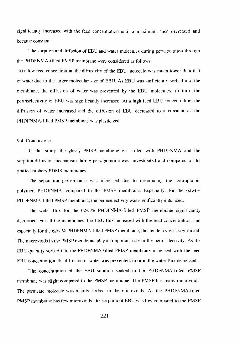
significantty increased with the feed concentration until a maximum, thell decreased and
became constant.
The sorption and diffusion of EBU and water molecules during Pervaporation thr【)ugh
the PHDFNMA-fiiled PMSP membrane were considered as follows.
At a且ow feed concentration、 the diffusivity of the EBU molecule was much lower than that
of water due to the larger molecular size of EBU. As EBU was sufficielltly sorbed il]to the
membrane, the diffusion of water was prevented by the EBU molecules、 in turl)、 the
permselectivity of EBU was sigllificantly increased. At a high feed EBU concelltratio1L tlle
diffusion of water increased and the diffusion of EBU decreased to a constallt as the
PHDFNMA-filEed PMSP membrane was plasticized.
9.4Conclusions
In this study. the glassy PMSP membrane was f川ed with PHDFNMA and tlle
sorption-diffusion mechanlsm during pervaporation was illvestigated alld compared to the
grafted rubbery PDMS membranes.
The separation performance was increased due to introducillg the hydr()phobic
polymer, PHDFNMA, compared to the PMSP membrane. EspeciaHy, for the 62wt%
PHDFNMA-f川ed PMSPmembrane, the permselectivity was significantly enhanced.
The water flux for the 62wt%PHDFNMA-fiHed PMSP membrane sigl浦cantly
decreased. For all the membranes, the EBU flux incre段sed with the feed concentration, and
especially for the 62wt%PHDFNMA一佃led PMSPmembrane, thistelldency was significant.
The microvoids in the PMSP membrane play an important role in the permselectivity. As the
EBU quantlty sorbed into the PHDFNMA-f川ed PMSP membrane increased with the feed
EBU concentration, the diffusion of water was prevented. inturn, the water tl ux decreased.
The concentration of the EBU solution soaked in the PHDFNMA-filled PMSP
membrane was slight compared to the PMSP membrane・The PMSP has many microvoids・
The permeate molecule was mainly sorbed in the microvoids・As the PHDFNMA-f川ed
PMSPmembrane has few microvoids, the sorption of EBU was Iow compared to the PMSP
221

membrane.
The sorption and diffusion of EBUand water molecules dロring pervaporation through
the PHDFNMA-filled PMSP membrane were considered as follows by calculation of the
apParent separation factor during diffusion(αD);
At a bw feed concentration, the diffusivity of the EBU mdecule was much lower than that
of water due to the larger molecular size of EBU. As EBU was sufficiently sorbed into the
membrane, the diffusion of water was prevented by the EBU mo且ecules, in turn, the
perm g. electi vity of EBU was significantly increased. At a high feed EBU concentration, the
diffusion of water increased and the diffusion of EBU decreased to a constant as the
PHDFNMA-fiHed PMSP membrane was plasticized. The permeation behavior of the
PHDFNMA-f川ed PMSP membranes were differ from the grafted rubbery PDMS
memb「anes.
9,5Ackllowledgments
Tlle authors thank Dr. Masaharu Asano of the Japan Atomic Energy Research Institute
for his kind permission and helpwith the 60Co irradiation.
9.6References
l)T.Nakagawa,ルf‘’ku(Me〃ibrane),20,156 G 995).
2)T.Nakagawa. T. Watallabe, M. Mori, K. Nagai,ACS Swmposiutn series 733,68
(1999).
3)T.Nakagawa、 T. Arai,Y. Ookawara, K. Nagai, Setプ’Gakkaishi,53,423(1997).
4)K。Nagai,T, Nakagawa、ノ.ルle〃~わr。∫ci,,105,261(1995).
5)K.Nagai.T. Nakagawa,」「.ルfe〃ihr. Sci..105、26且(1995).
6)K.Nagai.T. Nakagawa,ノ.」ρo 4N,〃~. Sci., Part 8ゴ)olv〃1。 P乃y∫.,33,289(1995).
7)K.Nagai,T. Nakagawa.ノ。ハρ!フ1. P/.}’n~..∫ビ’.,54.1651(1994).
8)K.Nagai, HigUchi. T. Nakagawa、」「.App’.」PtV〃!.∫ぐ~.,54,1353(1994).
9)K.Nagai, Higuc hi. T. Nakagawa,ノ.Aρp’. P’}・〃~. Sci.,54,1207(1994).
222

10)S.Asakawa, Y. Saito, K. Waragai、T. Nakagawa,α∬3{7♪ご’ratit)〃P!〃ゲノ(w’θ〃,3、 i j 7
(1989).
lDT. Nakagawa, T. Saito, S. Asakawa. Y. Saito, G‘~s Sc)ρごlr‘~1’θ〃1)‘’rlti(’(lti()〃,2、3
(1988).
12)H.Shimomura, K. Nakanishi. H. Odani. M. Kurata. T. Masuda, T、 Higashimura.
κo∠)blt~∫ノ2i Ro’ihunsノ?〃,43,747(1986).
13)K.Takada, K. Matsuya, T。 Masuda, T. Higashimura、ノ. Aρρ!. Pθ!},〃~. S(ゾ..30、1605
(1985).
14)S.Mishima, T. Nakagawa,ノ。 Appl. Po4wη.3‘ゾ,75.773(2000).
15)S.Mishima, T. Nakagawa,ノ. Appl. P‘小’η. S(・i.,73,1835(1999).
16)S.Mishima, H. Kaneoka, T. Nakagawa,ノ. Appt. Pθ!き・〃~.∫c’.,71、273(1999).
17)S.Mishima, T. Nakagawa, Kobunshi Ro’ihui~.s’ノlu,54,2目(1997),
223

Chapter 10. Condusions
The PDMS membranes were grafted by fluoroalkyl methacrylates(FALMA)using
various irradiation s()urce. FALMA had the effect of increasing the selectivity for VOCs. The
grafted PDMS membrane had the difference of polymer structure by various irradiation
methods。 The permeation properties of the various grafted PDMS membranes were
characterized.
The basic permeation behavior f()r PDMS membrane was investigated. The hydration
effect on the sorption-diffusion mechanism for various organic compounds is important
phenomena for permeation behavior and was investigated in pervaporation through the
PDMS membrane. The water molecules hydrate the solute molecuies. The motion of the
water lllolecules are prevented in the solute vicinity. The water flux increased until a
maximum at a Iow feed solute concentration because the hydration promoted water diffusion.
However, at the high feed concentration, soiute was concentrated in the PDMS membrane
and permeate. Almost all water molecules are concerned with hydration when the
concentration of(water molecules)/(solute molecules)is the salne as the hydration number,
When the actual concentration was over this concentration, the water molecules hydrate to
several solute molecules and皇he motion of the water molecules is prevented. During
pervaporation, the solute was concentrated in the PDMS membrane and the diffusion of
water molecules was prevented. When the dissociate sohlte mole fraction was a low, the
concentration of permeate solution was a low mole fraction and the degree of dissociation is
Iligh. Hence, the permeatioll of organic ions affected the total dissociate solute permeation.
The sorption selectivity of organic ion is low. The organic ion molecules is larger than water
molecule and the diffusivity is not so high. The enrlchment factor of dissociated compounds
was low ill the solution with a high degree of dissociation. At the high feed concentration,
亡he solution was concentrated in the tnembrane and the degree of dissociation is low. The
solute has high sorption se且ectivity. The solute flux significantly increased with increasing
feed concentration until hydration prevents diffusion. The diffusivity of so畳ute and water
molecules are prevented by hydration when the concentration of(water molecules)/(solute
224

Tabie iO.1 Various grafted PDMS membranes in thisst【ldy
irrudialk}n
S〔}t且rcC
lrradiaこk、n
melh(x」
1)C .9 rcC oi’
91・af、1inL, Mcmbranc s1ructUrc
MCmhrallc
strcn9lh
SCParatk}n faClor
(α・rC一 卜.lu\
Relationshipl』ccd
c(》nccntrし由ol1ししnd
りCr1τ1Ca【C conCCn【raIl(、n
卜」
m⊃
ヨ
uV
卜’.lcc芝r{}n
bCan1
PiaSma
simultam{Lr(、us
i【’1’adialk)n
Prcirradiatk》1】
Prcir「lidiu【ic、n
Aroundl wt c/,
~ lo“.t「.’i
~ 1〔}、、t「1~
Likc PI)MS
Brilt]C
1.ikc 1)1)MS
930
((,.025、vtつl fecd)
日1)f)
(0.(. p25wtつl fccd)
1800
{0.025、、t「4 ゴccd)
3(X} iL(、、、 f』ccd
Cし、nCCntratlし}11[
2891τゴ2h-2
L(O.025、、.t‘/(ilccd)
γ.rux
120tam-2h-2
‘O.025、、t 「、ti l’CL・(.i〕
32 L,111-2h-2
し(〔. j,02 s、、1’”i ガccd♪
79〔Hi:h fccd LCt,nCentr’ttti〈,111
~ 1209In-2h一ユ
L (1.‘ハ、 ゴccd
CL、nし・cntrとttiい「11
Lincar
SiRlui【anc(、US
il-1一こ1し1iしL【i~、11
18、、ピぞ ~
220“t‘.iSomc briuic ~2300
rHight-ecd しCし、INCT]tl’Lt乳i〈)ni
1」ncar
ljl]C;u’
N〔、t linCdr
PDMS 4(x}
10.0ユ5、、ゼ;1』 モモпj
つ つ 60ym--h-- LIO.0ユ1~、、lf’ 1’ccd
1.lnCd「

molecules>is the same as the hydration number. Et is concluded that not only the volume of
penetrate but also the hydration considerably affect on the diffusivlty-t was suggested that
the enhancement of 1 olubility of PDMS membrane was important to minimize the effect of
the selectivity decrease for dissociate penetrates.
Various grafted PDMS membranes inthis study are shown in Table 10.1.As the first
step of improvemenL the PDMS membrane in which FALMA and a】kylmethacrylates
(ALMA)were sorbed、 was irradiated by UV and uti且ized in pervaporation. The polymerized
FALMA and ALMA were contained in a modified membrane. The contained amounts of
FALMA alld ALMA were low, around lwt%. The almost same vaiues were obtained for
each FALMA and ALMA。 The sorbed TCE in the modified membrane increased with
increasillg length of重he f】uorinated side chain of FALMA, i.e., the number of伽orine
atoms. The membrane that showed the best separation performance was the membrane
having the highest TCE concentration in the sorbed solution. It was concluded that the
partition coefficieIlts for chlorinated hydrocarbons increased with the increase in n-
tluoroa亘kyl chain length of the n-fluoroalkyl methacrylates、 and, in turn, the permselectMty
increased. With increasing feed concentration, water diffusMty decreased, Due to the
introduction of a hydrophobic polymer, FALMA, the TCE quantity sorbed into the
membrane was so high that重he diffusion of water was prevented、 inturn, the flux decreased.
The PDMS membrane was grafted by electron beam which woutd be expected to give
m(,re grafted amount than UV, The effect of sdubmty and diffuslbility of a monomer on
graft polymerizati(}n by electron beam according to solubility parameter, octano1-water
partition coefticient(Pow)and the molecular volume of the mollomer was investigated。
When the difference of 6solN.ent alldδpol}・mer is smaller, so且vent and polymer are mixed more
h()mogeneously・The difference ofδFALMA andδP[)Ms is small but the sorpted FALMA
amount in PDMS membrane was low. The grafted amount was not affected by the solubility
parameter. The difference in the sorpted amount or grafted amount was little when
considering the difference of the logPow. The sorpted amount for ALMA that have low
molecular vohlme was high. The sorpted amount fbr FALMA that have high molecular
226

volume was)ow. Compared ro each other ill the same group of FALMA or ALMA. the
sorpted and grafted amount for the mollomer which has low molecular volume was high、 and
the sorpted and grafted amount for monomer which has high molecular volume was low.
The various grafted amounts were obtained for FALMA and ALMA in different t’roTII tlle
modlfjcation by UV irradiation.
The pervaporation for the PDMS membrane. PDMS membrane irradiated by electron
beam, grafted PDMS membranes was investigated. The tota且flux fbr the irradiated PDMS
membranes by electron beam was high compared to the ull-irradi飢ed PDMS membrane. lt is
thought that the PDMS membranes were made brittle by electroll beam irradiation. FALMA
grafted PDMS membranes showed excellent sorptioll and pervaporation separation
performance. Among them, PFPMA grafted PDMS membrane which had a high grafted
amount and FISi ratio had high permselectivity for TCE. h叩ervap()ration through the PDMS
and grafted PDMS membrane, the TCB concentration and TCE伽x in the permeate were
increased with increasing feed concentration. In the grafted PDMS、 the best separatioll
peIformance was shown, due to the introduction of the hydrophobic polymer.
poly(FALMA).
The PDMS membrane was improved by the graft polymerization with lH,IH.9H-
hexadecafluoronony且methacrylate(HDFNMA)by plasma, which had a long n-fl uoroal ky且
chain and the effect on increasing the selectivity for VOCs with low reacted amく)unt. The
plasma technique can perform radical formation on the surface of the polymer materials and
give little damage to them. When the pervaporation is used as analytical method, it is
expected that the relationship between the feed concentration and the permeate corlcentratk,n
is observed to be linear as well as for PDMS. The use for easy quantitative analysis of the
pervaporation through plasma-grafted PDMS membranes was investigated. After the
irradiation, the degassed HDFNMA was introduced into the reactor, the PDMS membranes
were soaked in HDFNMA and then grafted. The graft polymerization was promoted in the
PDMS membrane. The degree of grafting on the inside and reverse side of the PDMS
membranes was lower than on the surface.
227
The radical produced on the surface significant且y increased with increasing plasma
power. The degree of grafting and oxidation simultaneously increased. The flux of the
grafted PDMS membrane increased with increasing piasma power. The degree of grafting
increased with increasing plasma irradialion time。 The flux of the grafted PDMS membrane
was constant regardless of the plasma irradiation time. When the PDMS membranes were
irradiated a目OW for l80s and grafted, the grafted membranes were not brittle and the
perinselectivity increased. The hydrophobicity of the grafted PDMS membranes was
et’fecti vely increased due to introducing the hydrophobic polymer, poly(HDFNMA). Because
the grafted amount of the plasma grafted PDMS membrane was little and the advantage of
rubbery PDMS membrane remained、 the relationship between the feed concentration and the
permeate collcentration was observed to be linear. The feed concentration is able to be
introdticed from the permeate concentration, The pervaporation through the grafted PDMS
membrane couid to be used for easy quantitative anaiysis.
The sorption alld diffusion of the permeate solute is important for the permeation
behavior same as the solute properties and interaction. The sorption and diffusion for various
VOC-water mixture during pervaporation through the PDMS membralle and HDFNMA
grafted PDMS membrane by plasma preirradiation were investigated. The grafted PDMS
membrane showed the best sorption and separation pe!formance. During pervaporation, the
components which permeate and membrane interface each others. The phenomenon was
sigηiflcantly observed in pervaporation for the ternary mix加re through the grafted PDMS
lllembrane. The TCE flux was prevented by benzene during pervaporation of the TCE-
bellzene-water mixt恥1re through the grafted PDMS membrane.
PCE and toluene have high logPow and had high solubility in both the PDMS
membralle and the gr抽fted PDMS membrane. BBU have且ow logPow and had low solubility
mboth the PDMS membrane and the grafted PDMS membrane. The solubility for EBZ was
low in both the PDMS membrane and the grafted PDMS membrane, while EBZ has a high
k)gPow. The solubility for compounds in a membrane is affected by its dispersion and
polarization. Po且arization can be considered using the Pow value. The ability of dispersion is
228

determined by diffusivity・The degree of sorption for EBZ was Iow compared to the other
VOCs. The molecular vo】ume of EBZ is much greater重han the other VOCs,therefore. the
diffusivity of EBZ islow. Hence, the degree of sorption for EBZ was k)w and the solubility
for EBZ was iow in the membrane. PCE has four Cls with a much larger molecしllar vdume、
therefore, the diffusivity is very low.
Permselectivity is determined by the sorption and the diff’tision characteristics of the
permeating components inthe membrane. Theρermse】ectivity of PCE and重()luelle was lligh.
Because the solute quickly permeates in the rubbery membrane like PDMS, permse且ectivity
was not afrected by diffusivity. So且ubility significantiy affects the permselectibity during
pervaporation through the hydrophobic rubbery membrane. The soiution-diffusion
mechanism for various VOCs based on their properties were important
The PDMS membrane was improved w童th graft polymerizatjon of HDFNMA, which
has the effect of increasing the se且ectivity for ch且ori nated hydrocarbons. by a 6()C(, source
and characterized the grafted PDMS membrane. Simultaneous irradiatioll is a method ill
which Ihat monomer and polymer are irradiated simultaneous]y. The grafted alllout)t by
simultaneous irradiation was more than by preirradiation methods, alld the permeatioll
behavior w川be expected to be differ from the rubbery unlreated PDMS membra,1e and重he
grafted membranes by preirradiation method. The grafted and polymerized HDFNMA by a
60Co simu且taneously irradiation was swo畳len but not dissolved in solvent, diffe re nt frく)m
poly(HDFNMA)grafted by electron beam and p且asma preirradiation. The grafted PDMS
membranes had a microphase-separated structure, Le., a separated structure of PDMS and
grafted HDFNMA. The graft polymerization started with one region ln the PDMS
membrane. More HDFNMA was grafted on the poly(HDFNMA)domain than the PDMS
domain due to the affinity of HDFNMA for poly(HDFNMA), The poly(HDFNMA)domain
was grown by grafting. The poly(HDFNMA)domains were dispersed lllto the entire PDMS
membrane homogeneously by irradiation,
The grafted PDMS membrane by simultaneous irradiatめn was applied to
pervaporation, and theirpermeation behavior was compared to the PDMS membrane and the
229

grafted PDMS membranes by preirradiation method. ln the grafted PDMS membralle. the
concentration of TCE sorbed lnto the membrane was high, due to the introductlon of the
hydrophobic pojymer, poly(HDFNMA)・The membrane that had a high so】ubility selectivity
for TCE showed great separation performance。 The permeability of the PDMS phase was
significantly great and that of the poly(HDFNMA)phase was too low to affect the whole
permeation of the grafted PDMS membrane directly. However、 poly(HDFNMA)had a much
stronger affinity for TCE than for water. Thefore, the permeability and permselectivity of
TCE on the surfhce of poly(HDFNMA)and PDMS were high, and the permeation oll the
surfhce played important role in the permeation lhrough the grafted PDMS membrane. At a
low feed concentration of TCE solution, the diffusivity of TCE molecules must be much
lower than that of water due to the larger molecular size of TCE. At a high concentration of
TCE s. olution,TCE was sufficiently sorbed into the membrane, so that the diffusion of water
was prevented by the TCE molec田es;in turn、 the permselectMty of TCE was increased
significantly. The interesting permeation phenomena was obtained for this grafted
membrane.
ln this study. the permeation properties of the grafted PDMS membranes by various
irradiation methods were characterlzed. The permeation behavior was differ from rubbery
untreated PDMS membrane and the little gra食ed PDMS membrane by preirradiation. It was
c且eared thal the membralle stmcture effected on the permeatlon behavior significantly.
Fu質her, PMSP membrane was filled with poly(HDFNMA)(PHDFNMA)and the
9. orption -diffusion mechanism in pervaporation was investigated compared to the grafted
PDMS membrane. The separation pe㎡ormance was increased due to introduce hydrophobic
polymer. PHDFNMA compared to PMSP membrane. Adow feed concentration、 the
diffusivity(、f EBU molecule was much lower than that of water due to the larger molecular
size of EBU. As EBU was sorbed enough into the membrane. the diffusion of water was
prevented by the EBU molec田es, in turn, the permselectMty of EBU was increased
significntly. At high feed EBU concentration. the diffusion of water increased and the
diffusion of EBU decreased to be constant as the PHDFNMA-fi且led PMSP membrane was
230

plasticized. In case of the HDFNMA grafted PDMS membrane by simultaneoug. irradiation,
the membrane was not plasticized because the PDMS membrane is rubbery polymer btlt
crosslinked、 Because the PMSP membrane is glassy polymer but has high solubility for
organics, the PHDFNMA-f川ed PMSP membrane was plasticized and the permeatioll
behavior was differ from the grafted PDMS membrane.
231

Appendix. Analysis of Hydrophilic Volatile Organic Compounds by
Per▼aporation(for chapter 6)
A.且lntroduction
In recent years, the various environmental organic pollutants that infiuence human
health have become a social prob且em. The analysis technique to measure most of these
compounds is comp[ex and requires a Iong timeL2. For example, organlc compounds to be
analyzed are extracted with solvents, absorbed on an adsorption column and dist川edL2.
However. the water samp且es are requi red to concentrate before being su切ected to the
analyzer. It is also important to concentrate and analyze the water samples quickly at the
field. Hence, pervaporation as easy extraction technique for such an analysis has been
studied and used3、日. If a straight line relationship is apParent for the concentrations on the
fセed side and on the penetration side, it can be utiiized as the calibration curve and apPlied as
asimple analytical method.(described in chapter 6)Up to now, various environmenta且or-
ganic pollutants sensitively and simu且taneous且y analyzed by a gas chromatograph mass
spectrometer(GCMS)which can detect them ofμg/11evels. As the introduction of liquid
water to the GC-MS shou且d be avoided, the introducing of a permeated vapor to the GC-MS
without coohng provides a cost savings. The extraction of volatile hydrophilic organic
compounds from water has difficu藍ties}・2 and a conventional extraction method has been
required. A Polydimethylsiloxane(PDMS)membrane、 which has a high permeability to
gases alld liquids,i2 can contri bute to an easy and sensitive analysis. In this study. the
permeated vapor of the volatile hydrophihc organic compounds in the pervaporation trough
PDMS was su切ected to GCMS and analyzed. The degree of linearity and sensitivity was
investigated and Its app]icability as an analytical method was evaluated.
A.2Pervaporation experiment and analytical measurement
Commercial PDMS membranes(Fuji Systems Corporation),50μm thick, were used
throughout thls study. Butyl acryiate,2-butanone,1 ,4-dioxane(Special grade, Wako Pure
232

Chemical Industries. Ltd.). acrylonitrile、methyレt-buty且ether, bls(2-chloroethyl)ether
(Special grade, Kanto Chemical Co.. Inc.), methanol, nuorobenzene ill methallo1(1mg/mD
and bromofluorobenzene in methanol dmg/mD (fbr volatlle o1璽gallic c()mpounds
measurement, Kanto Chemical Co.,Inc.)were used as received. The physical and chetnicaI
properties of the compounds used in this study are listed in Tab且e A l.
Table A l Various hydrophilic organic compounds used ill this study
Com ounds
Molccular Boiiin9 point Walcr solubilil}
wciuh1℃ “’t・/t
卜brmerじxtraCtloll
mcth〈xjs
Mcこh}1一山u[yl elher 88.15 55.2 Shghlly solt‘ble l’urge&’1’t’UP
Acr)’lonitrite 53.03 77.3 7.5 S〔Caln distillatio「1&Sol、’cnt
(〔、r solid phusc)e、tractk〕n,
Pu11亀1c&’「ra,
2-Butanone 72.1 79.6 22.6 S〔}1、¢1)textraction
L4-Dk}\anc 88.1 101.6 Soitib]e Solid phasc eNtractkon
But>’1 acr》’latc 128.17 146 O,2
Bis(2-chloroeth、bcther v
143.Ol 178。5 】『1 Slcam distillaIk川&S〔}lid
phasc cx1rac【k)n,
PU「,C&Traり
FI uorobcnzcne
(lntcrnal standcrcd 1)
96.1
↓Bromofl uo「obcnzenc
(lntcrnal standered 2)
175
The pervaporation experiments were performed as in a previous studyB. The
permeated vapor was cooled to a Iiquld and s呵ected to gas chromatography wit団ame
ionization detection(GC-FID). The enrichment factor,βpv, was calculated as
βpv=YIX (A」)
233

where X aIld Y denote the concentration of the solute in the feed and permeate solution、
respectively・
This analyticaE pervaporation method was performed as reported by Lロque de Castro et
aL4’6. ln this analytical pervaporation, the permeated vapor was su切ected to GC-MS
withou!cooling. Fluorobenzene and bromofluorobenzene were used as the internal standards
to minimize the analysiserror.
A.3Results and discussion
A.3」Pervap〔}ration for hydrophilic volatile organic compounds
Table A2 Enrichment factors for pervap()ration
Com ounds
Enrichment factor
In pervaporatlon
at ODOswt%feed
COficentration(±SD.)
25℃ 60℃
Methyl-t-butyl ether
Acrylonitrile
2-Butanone
I.4-Dioxane
Btityl acryjate
Bis(2-chloroethy1)ether
41±5,7
34±6,3
36±6,7
20±3,9
45±4.3
26±5,6
104±19
87±9.3
102±27
74±17
68±8.9
77±10
a:n=4
S.D.:Standard dlvision
The feed and permeate concentratlons at equilibrium during the pervaporatlon
measurement were determined by GC-FID. The enrichment factor (βpv) of the
234

卜」
ヨα
(承妄)2・・Φ∈」Φα夏Φ⊂・。×o マ寸ド
0.15
0.1
0.05
0
0 O,001 0.OO2 0.003 0.004 0.005
1,4-dioxane in feed(wt%)
(ま妄)2・5Φ∈」Φα二」Φ5Φ(}ぢo」o毛&)°。団
0.8
0.7
0.6
0.5
0.4
0.3
0.2
0.1
00 0.OO1 0.OO2 0.003 0.004 0.005
Bis(2-chloroethyl)ether in feed(wt%)
Fig. A l Effect of feed concentration on permeate concentration for hydrophi且ic volatile organic compound-water
mixtures during Pervaporation through PDMS membrane at various temperatures:(口)at 25・C.(△)40。C.(O)
600C. open:for L4-dioxane, closed:for bis(2-chloroethyl)ether.

卜D
ヨO
810-5
(‘
6 6 6
0 0 0
11 1 1
6 4・ 2
E\9)×⊇も岳x9マ寸ド
N
00 0
ロ01
44
(£
コ01
34
ロ01
24
ロ011 4
0
N∈\g×⊃=」Φ=ρΦ(一ξΦ。」。三Q-N)・。評
@
@
@
@
@
@
@
c…
○
○
492 陛
939り陛△
40の030‘0020の001の0
1,4-dioxane in feed(wt%)
0.001 0.OO2 0.003 0.004 0.005
Bis(2-chloroethyD ether in feed(wt%)
Fig. A2 Effect of feed concentration on solute flux for hydrophMc volatiie organic compound-water mixtures
during pervaporation through PDMS membrane at various telnperatし1res:(□)at 250C、(△)40°C,(○)600C、
open:f6r L4-dioxane, closed:for bis(2-chloroethyi)ether.

hydrophi且ic volati且e organic compounds at each temperamre is given ill Table A2. The
relationship between the feed and permeate concentrations of the hydrophilic volatile()rganic
compound is shown at various temperatures in Fig. A 1,The relationshipbetweell
the feed and permeate concentrations was found to be hllear. lf a straighUine relatioils hip
between the feed and permeate concentrations is obtailled, the re且ationship call be utihzed as
ca置ibration curve. The hydrophilic volati且e organic compound f1 ux as a functk}n of the
concentration of the hydrophilic vola田e organic compotmds in the feed s()lution is sl】own at
various temperatures iTl Fig. A2. The relationshipwas observed to be且inear. lll thisanalytical
pervaporation, the permeated vapor was s呵ected to GC-MS without coolillg. Whell the
re且ationship between the permeate amount of solute vapor for a unit time、 i.e,、s olute flux and
feed solute concentration was found to be linear, it could be used as a ca且ibratk、n curve for a
simple analysis method. The flux of the hydrophilic volatile organic c(}mpounds was lligh a重
high temperature.
A・3・2Analytical pervaporation of hydrophilic volati置e organic compounds
The hydroph川c volatile organic compoulld solution with a known concentration was
introduced into the analytical pervaporation cel}. Theρermeated vapor was su切ecled to GC-
MS. The calibration curve was based on the relatio董iship between the solしltioll concentration
and the GC-MS peak area. The infl uence of temperature on the calibration cur>e f()r each
compound using this analytical method is shown in Table A3. At 25℃, the vapc)r of the
compounds was only slightly detected in the cell. When the vapor permeated at 25℃and
山einside of the cell was heated with a d ryer, each compound was detected. Als《), for some
compounds, the calibratlon curve became a straight line with good sensitivity when the vapor
of the compounds was permeated at 40℃and then ana且yzed. When the vapor of the
compounds permeated at 60°C was analyzed, for most of the compounds had ca且ibrati()n
curves that were straight」ines with good sensitivity. The operating temperaωre at 60℃was
the best for this analytical method. During the pervaporation, the vapor of the compounds
was cooled to a liquid and then analyzed. In this analytical method, the vapor of the
237

compouηds was analyzed wl1hout cooling, and at a bw operating temperature, the vapor of
the compoumds can not remalnas such and is adsorbed onto the inside of the celL
Table A3 Correlation coefficients of the ca亘ibration curve
ill thisanal tical method at various tem eratures
Corre亘ation coefficient
of the catibration curve
in this analytica置method
25℃ 40℃ 60℃
Methyl-t-butyl ether
Acrylonitrile
2-Butanone
1 ,4Dioxane
Buty且acrylate
Bis(2-chloroethyl)ether
73
52
72
58
73
93
一*
一*
一*
一*
一*
一*
0.996
0.900
一*
一*
0.995
一*
0.987
O.998
0.986
0.992
1.000
0.999
*:Not detected
m/z:Target ion inGC-MS analysis
The recc)very was examilled for various compounds in river water at 60℃. Each
comp⊂)und was added to the river water at 50r 200μg/L The concentration of the added river
water was obtahled from the vapor peak area using the calibration curve based on the vapor
peak area for the concentration of a known so且ution. The recovery(R%)and the coefficient
of variation(CV%)are shown in Tab且e A4. For a 200μg/l soh量tion, the recovery was
89、ll8%with a l6、29%CV value, For a 5陣g/E solution, the recovery was 8ト118%with a
6、33%CV vahle」n this study, the standard solution was made from distilled water.
238

Table A4 Recovery from the river samp且e using this analytica[
method at 60℃
Com ounds
5ppb
R(%)CV(%)
200ppbR(%) CV(%)
Methyl-t-butyl ether
Acry且onitrile
2-ButanOne
1,4-Dioxane
Butyj acrylate
Bis(2-chloroethyl)ether
04
X0
P8
W6
1 1
001
18
1 3 ユ」 - ー
Qノー1
1 聖
001
a:n=5
R(%):Average of recovery(%)
S tandard diN「isiOll of reCON CA((/t)
CV(%):Coefficjent of variation(%)= ×1(x}(t/()
AN’cragc o「rec()、「erき(t/t)
Since various compounds are contained in environmental water samples、 the concentration()f
the added river water is detected to be higher than the real concentration due to salting-out
effect. The control of such effect is being studied. This method can be a convenient way to
ana且yze hydrophilic vo)atile organic compounds inwater samples.
A.4Concjusion
An analytical pervaporation technique was applied to the extraction of hydroph日ic
volatile organic compounds in this study. During the pervaporation, the relationship between
the feed concentration、 permeate concentration and solute fl ux was found to be linear. and the
slope was high at a high operating temperature」n this analytical pervaporation technique, the
239
calibration curves for most of the compounds became straight Iines with good sensitivity at a
high operating temperature, Le.,60℃.
A.5Acknowledgment
The au重hors are grateful to the Fuji Systems Corporation for providing the PDMS
nleInbranes.
A.6References
l)The Environment Agency, J叩an, Reports for development of analytical methods of
orgallic compounds inJapan(1982~1998).
2)EPA, USA、Guidelines establishing test procedures for the analysisof pollutants, part
136.
3)1.Luiz de Mattos、 and E. A. G. Zagatto, AnaL∫(・’.,15,63(1999).
4)M.D. Luque de Castro, and J. M. FernAndez-Romero,ノ. Chrema’ogr. A,,819,25
(置998).
5)M.D. Luque de Castro, and L Papaefstathiou, TrAC,,17,41(1998).
6)LPapaefstathiou, and M. D. Luque de Castro、ノ.αr‘〃ηα’ogr.ん,779,352(1997).
7)LPapaefstathiou, and M. D. Luque de Castro,1’lt.ノ. Enレir‘,η.んtat. Chem.,66,107
(ig97).
8)LPapaefstathiou, U. B川tewski, M. D, Luque de Castro, and J. Fresenius,、肋αムChe’η.,
357、ll68(1997).
9)D.W.Bryce, A, lzquierdo、 and M. D. hlque de Castro,んza!.αピ〃~,,69,844(1997).
10)LPapaefstathiou, M. D. Luque de Castro. M. Va且carcel,and J. Fresenius,んヱα1. Che’η.,
354,442(1996).
目)i.Papaefstathiou, alld M, D. Luque de Castro,んla!.乙ご〃.,28,2063(1995).
12)T.Nakagawa.ルlak〃(ル惣〃1わrane).20、156(1995).
13)S,Mishima, and T. Nakagawa,ノ. App’. PQ 1.NT’rl.∫d.,73,1835(1999).
240
Recommended