ECE 301 – Digital Electronics
Sequential Logic Circuits:
State AssignmentAnd
State Minimization
(Lecture #20)

ECE 301 - Digital Electronics 2
State Assignment Problem
ECE 301 - Digital Electronics 3
State Assignment Problem Some state assignments are better than others. The state assignment influences the complexity of the
state machine. The combinational logic required in the state machine
design is dependent on the state assignment.
Types of state assignment Binary encoding: 2N states → N Flip-Flops Gray-code encoding: 2N states → N Flip-Flops One-hot encoding: N states → N Flip-Flops
ECE 301 - Digital Electronics 4
Example:
Design a FSM that detects a sequence of two or more consecutive ones on an input bit stream.
The FSM should output a 1 when the sequence is detected, and a 0 otherwise.
This is another example of a sequence detector.
FSM: State Assignment
ECE 301 - Digital Electronics 5
FSM: State Assignment
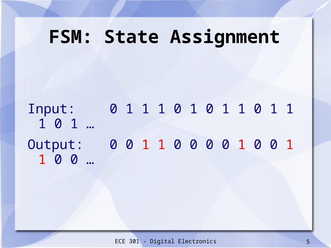
Input: 0 1 1 1 0 1 0 1 1 0 1 1 1 0 1 …
Output: 0 0 1 1 0 0 0 0 1 0 0 1 1 0 0 …

ECE 301 - Digital Electronics 6
FSM: State Assignment
State Diagram
C z = 1
Reset
B z 0 = A z 0 = w 0 =
w 1 =
w 1 =
w 0 =
w 0 = w 1 =
S0 / 0 S1 / 0
S2 / 1
ECE 301 - Digital Electronics 7
FSM: State Assignment
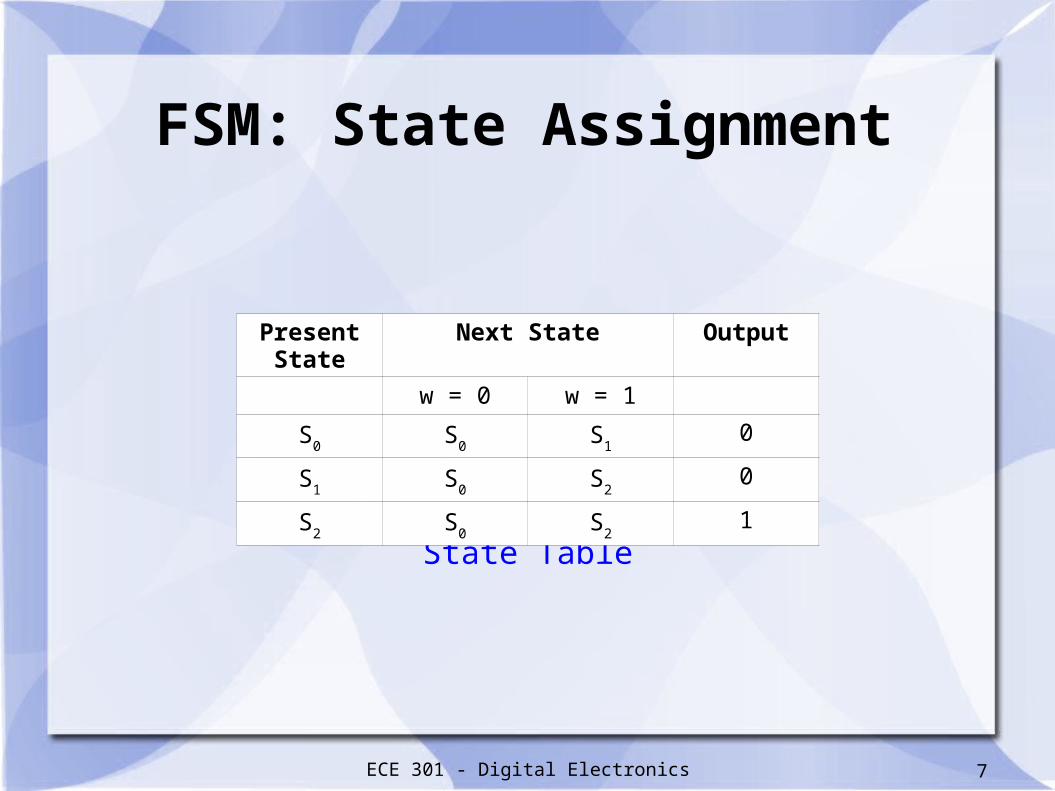
State Table
Present State Next State Output
w = 0 w = 1
S0
S0
S1
0
S1
S0
S2
0
S2
S0
S2
1
ECE 301 - Digital Electronics 8
FSM: State Assignment #1
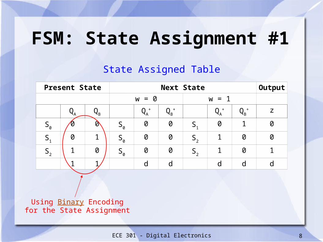
State Assigned Table
Present State Next State Output
w = 0 w = 1
QA
QB
QA
+ QB
+ QA
+ QB
+ z
S0
0 0 S0
0 0 S1
0 1 0
S1
0 1 S0
0 0 S2
1 0 0
S2
1 0 S0
0 0 S2
1 0 1
1 1 d d d d d
Using Binary Encodingfor the State Assignment
ECE 301 - Digital Electronics 9
FSM: State Assignment #1
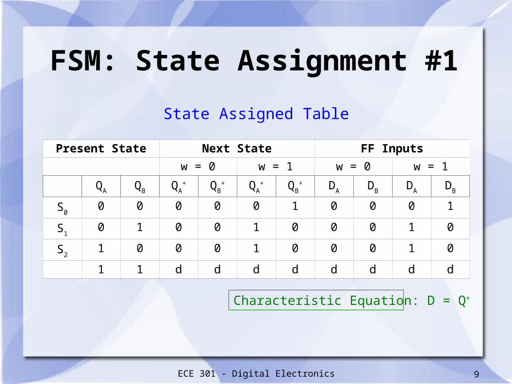
Present State Next State FF Inputs
w = 0 w = 1 w = 0 w = 1
QA
QB
QA
+ QB
+ QA
+ QB
+ DA
DB
DA
DB
S0
0 0 0 0 0 1 0 0 0 1
S1
0 1 0 0 1 0 0 0 1 0
S2
1 0 0 0 1 0 0 0 1 0
1 1 d d d d d d d d
State Assigned Table
Characteristic Equation: D = Q+

ECE 301 - Digital Electronics 10
FSM: State Assignment #1

ECE 301 - Digital Electronics 11
FSM: State Assignment #1
K-Map and Boolean expression for z
ECE 301 - Digital Electronics 12
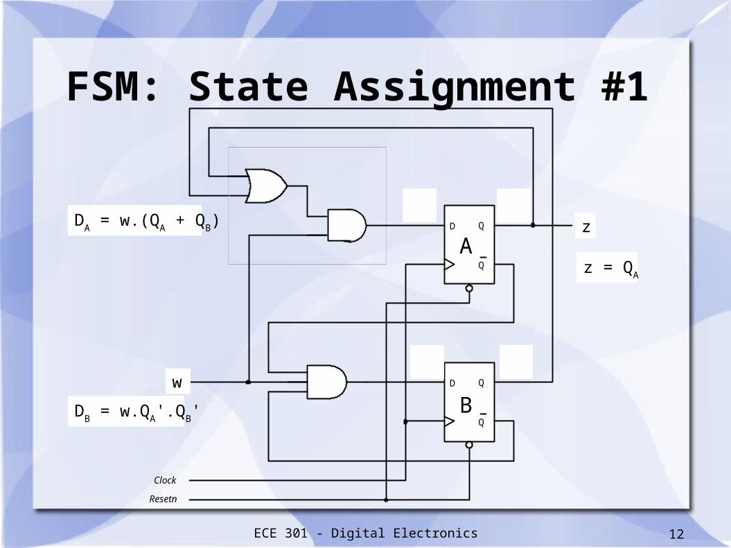
FSM: State Assignment #1
D Q
Q
D Q
Q
Y 2
Y 1 w
Clock
z
y 1
y 2
Resetn
A
Bw
zDA = w.(Q
A + Q
B)
DB = w.Q
A'.Q
B'
z = QA
ECE 301 - Digital Electronics 13
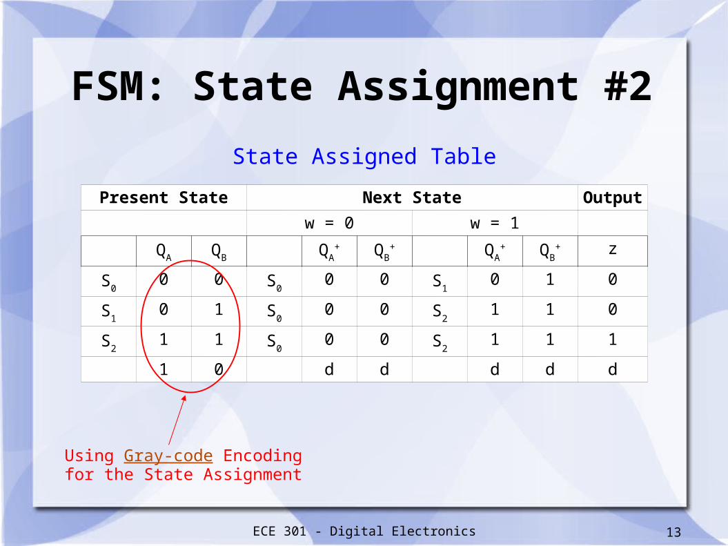
FSM: State Assignment #2
State Assigned Table
Present State Next State Output
w = 0 w = 1
QA
QB
QA
+ QB
+ QA
+ QB
+ z
S0
0 0 S0
0 0 S1
0 1 0
S1
0 1 S0
0 0 S2
1 1 0
S2
1 1 S0
0 0 S2
1 1 1
1 0 d d d d d
Using Gray-code Encodingfor the State Assignment

ECE 301 - Digital Electronics 14
FSM: State Assignment #2
Present State Next State FF Inputs
w = 0 w = 1 w = 0 w = 1
QA
QB
QA
+ QB
+ QA
+ QB
+ DA
DB
DA
DB
S0
0 0 0 0 0 1 0 0 0 1
S1
0 1 0 0 1 1 0 0 1 1
S2
1 1 0 0 1 1 0 0 1 1
1 0 d d d d d d d d
State Assigned Table
Characteristic Equation: D = Q+
ECE 301 - Digital Electronics 15
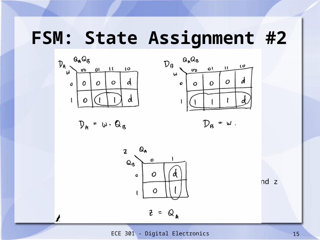
FSM: State Assignment #2
K-Map and Boolean expression for DA, D
B and z
ECE 301 - Digital Electronics 16
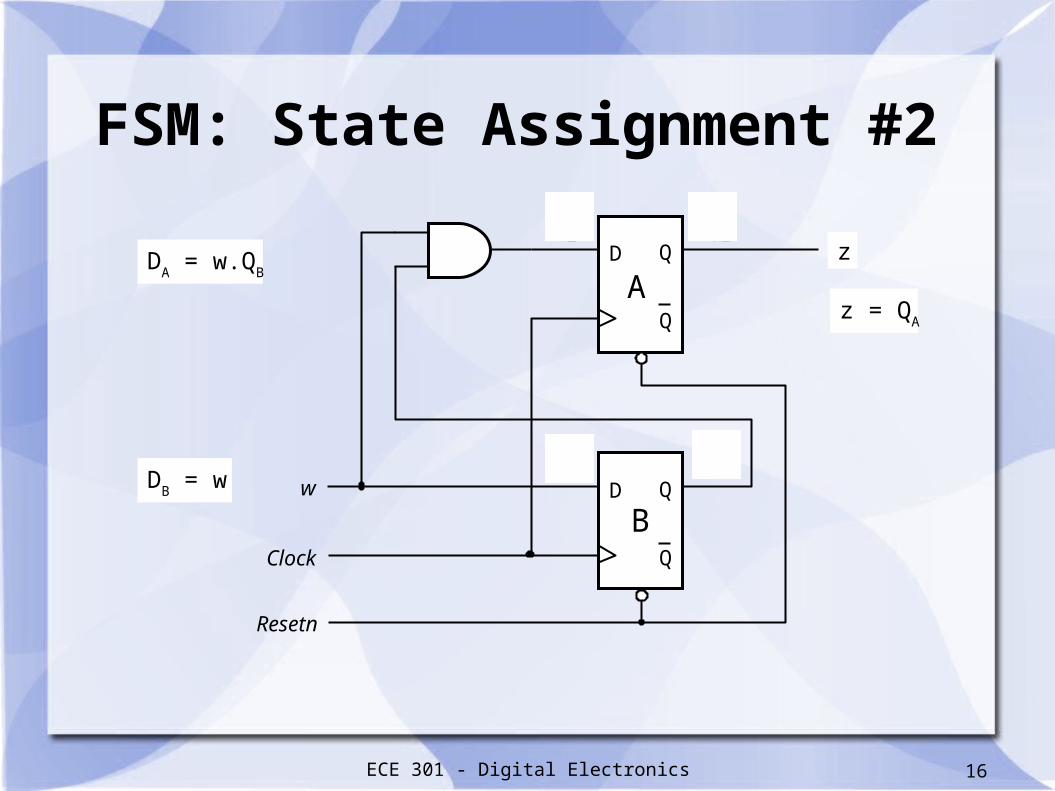
FSM: State Assignment #2
D Q
Q
D Q
Q
Y 2
Y 1 w
Clock
z
y 1
y 2
Resetn
A
B
DA = w.Q
B
DB = w
z
z = QA
ECE 301 - Digital Electronics 17
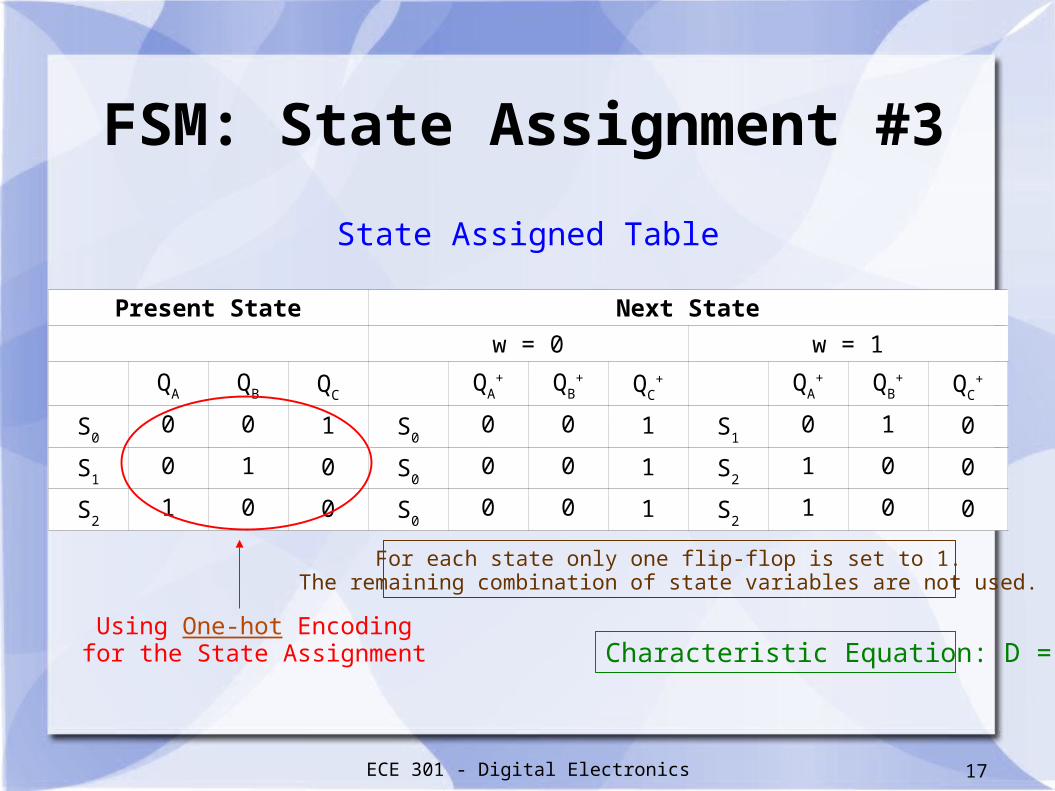
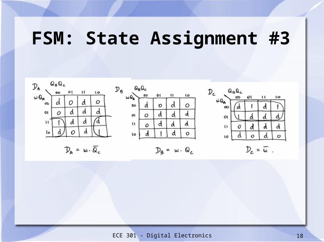
FSM: State Assignment #3
State Assigned Table
Present State Next State
w = 0 w = 1
QA
QB Q
CQ
A+ Q
B+ Q
C+ Q
A+ Q
B+ Q
C+
S0
0 0 1 S0
0 0 1 S1
0 1 0
S1
0 1 0 S0
0 0 1 S2
1 0 0
S2
1 0 0 S0
0 0 1 S2
1 0 0
Using One-hot Encodingfor the State Assignment
For each state only one flip-flop is set to 1.The remaining combination of state variables are not used.
Characteristic Equation: D = Q+
ECE 301 - Digital Electronics 18
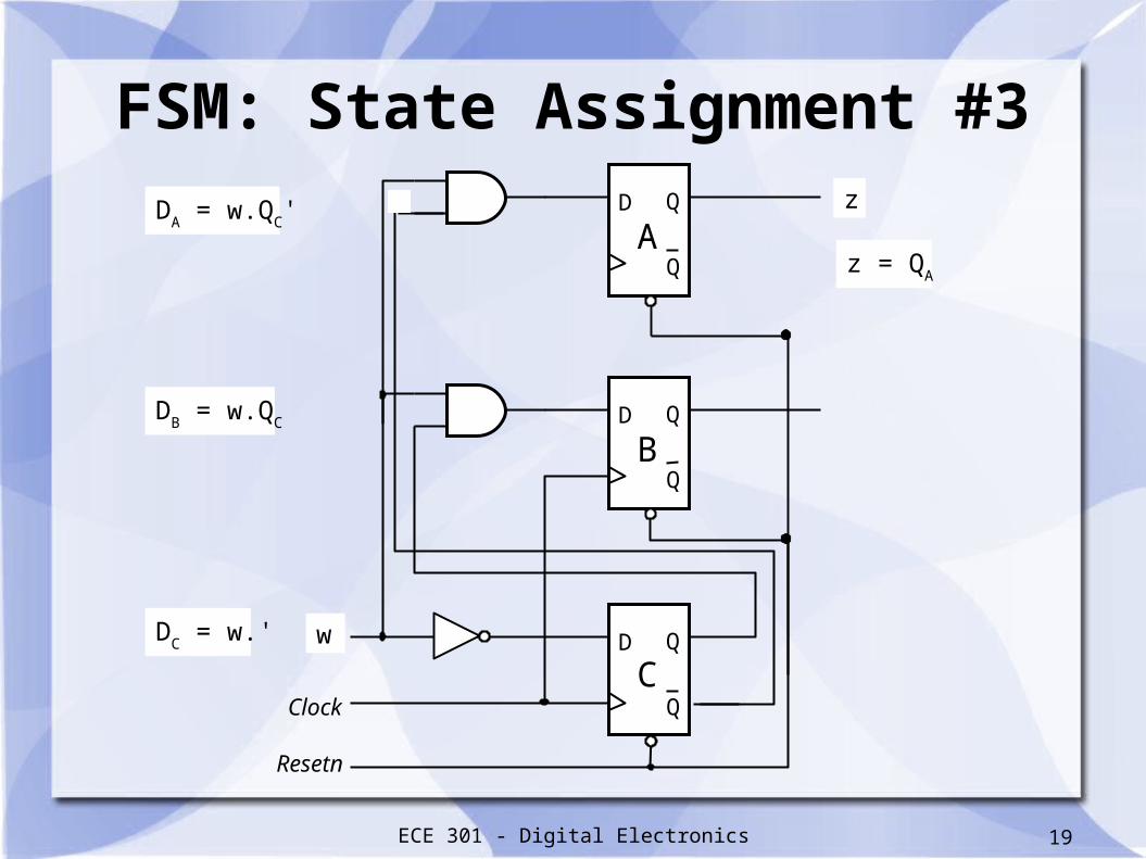
FSM: State Assignment #3
ECE 301 - Digital Electronics 19
FSM: State Assignment #3
Resetn
D Q
Q
D Q
Q Clock
D Q
Q
DA = w.Q
C' z
z = QA
A
B
C
DB = w.Q
C
DC = w.' w

ECE 301 - Digital Electronics 20
State Minimization
ECE 301 - Digital Electronics 21
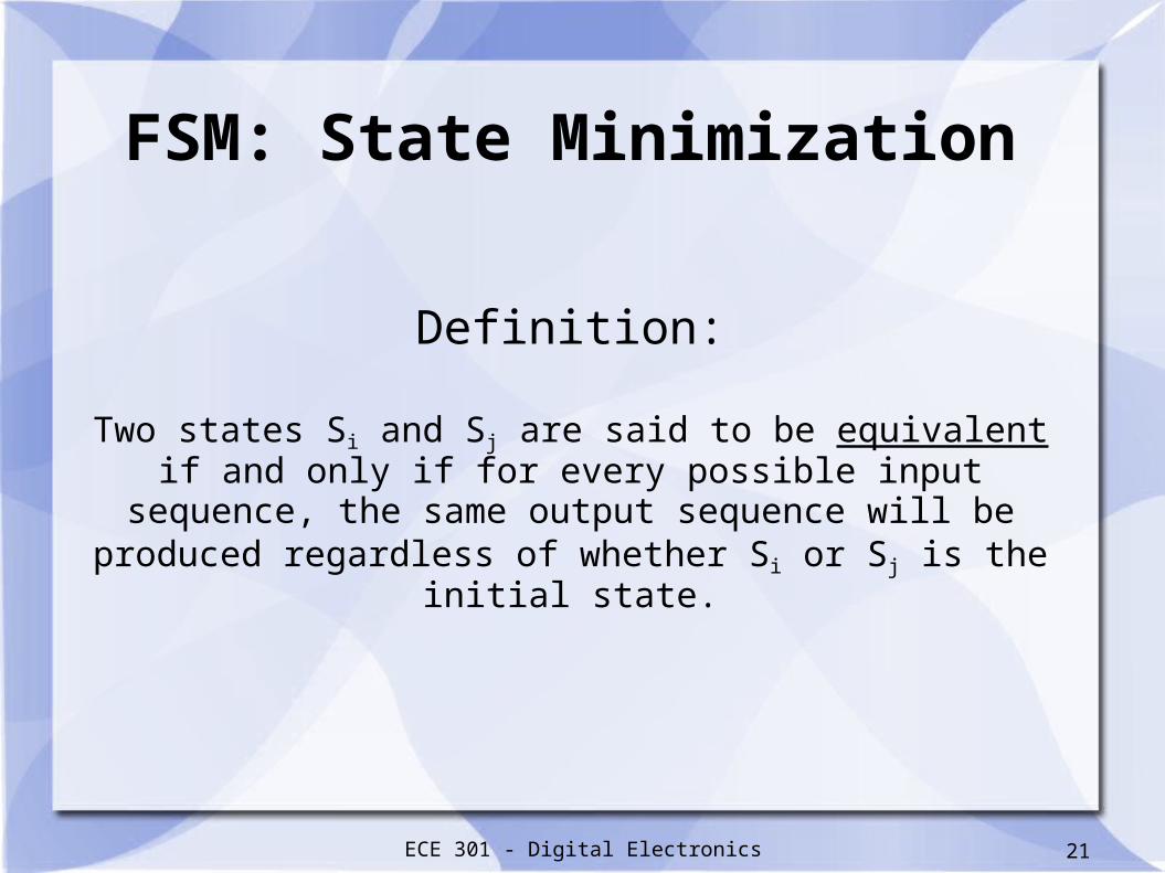
Definition:
Two states Si and Sj are said to be equivalent if and only if for every possible input sequence, the same output sequence will be
produced regardless of whether Si or Sj is the initial state.
FSM: State Minimization
ECE 301 - Digital Electronics 22
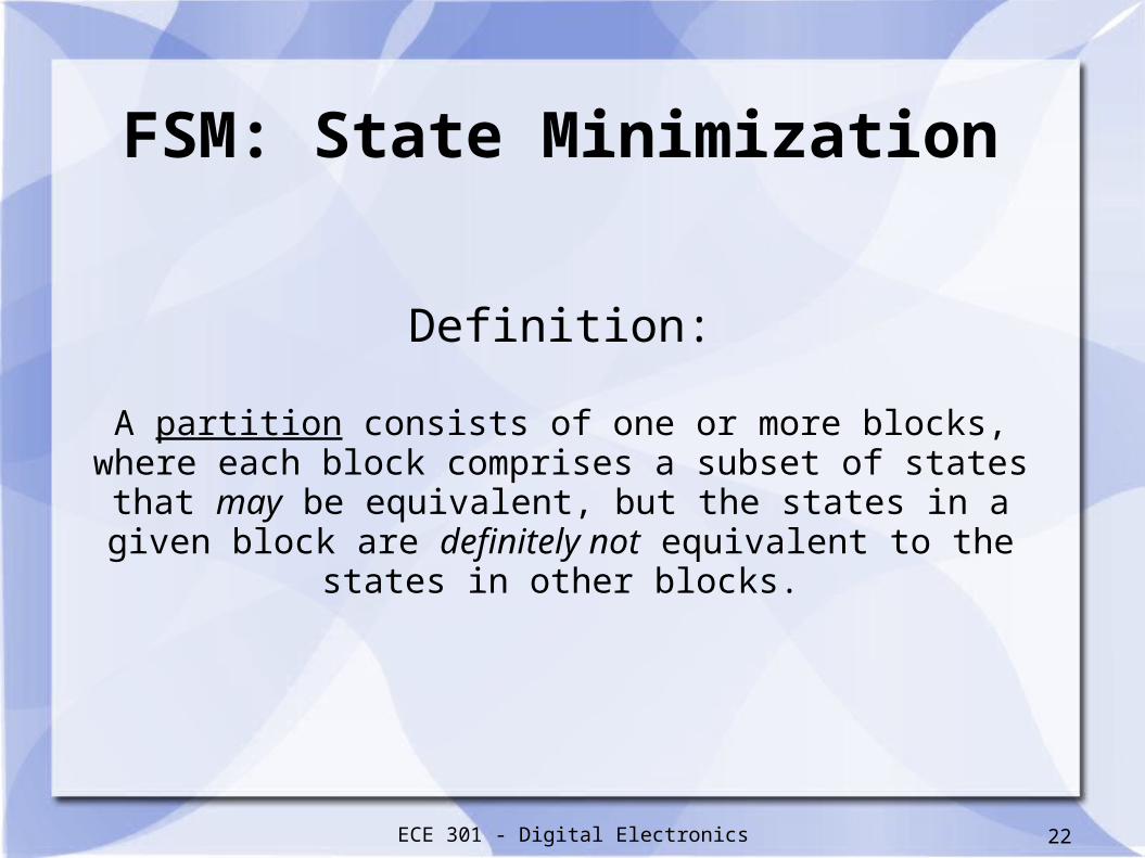
Definition:
A partition consists of one or more blocks, where each block comprises a subset of states that may be equivalent, but the states in
a given block are definitely not equivalent to the states in other blocks.
FSM: State Minimization
ECE 301 - Digital Electronics 23
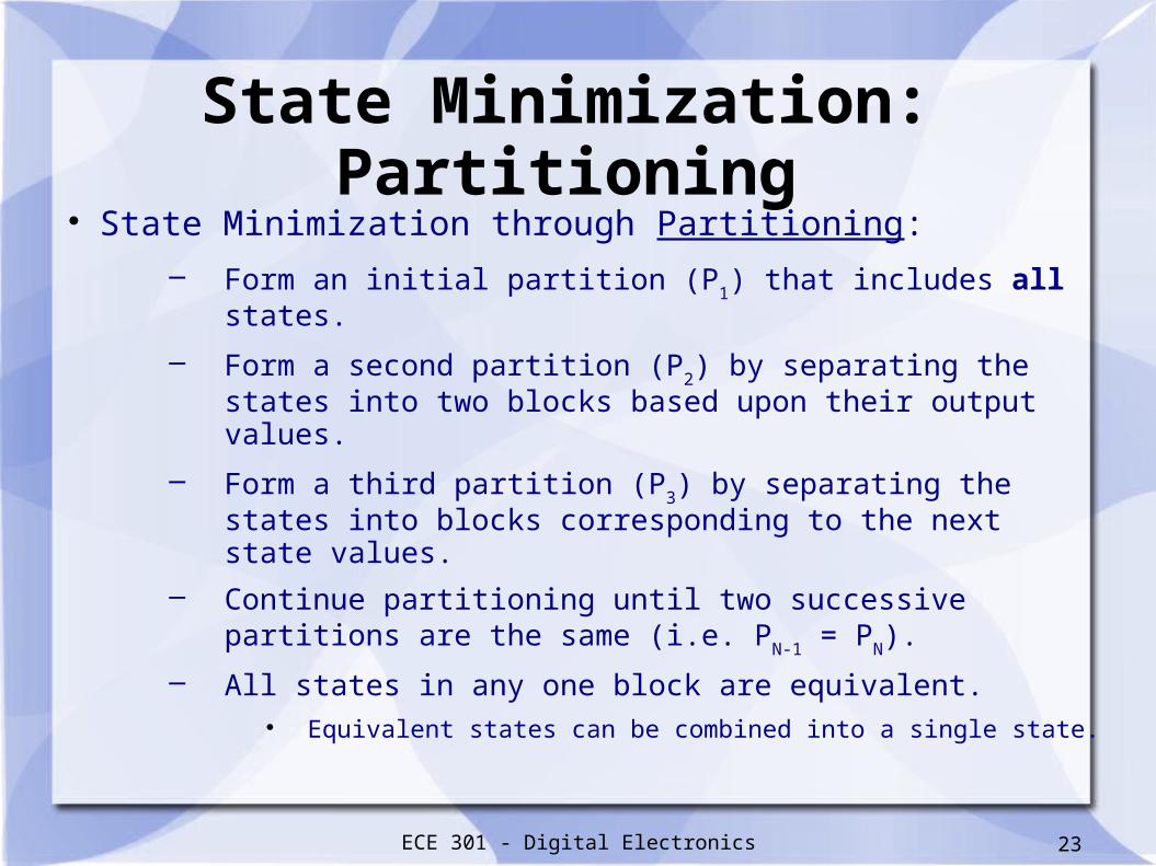
State Minimization: Partitioning State Minimization through Partitioning:
– Form an initial partition (P1) that includes all states.
– Form a second partition (P2) by separating the states
into two blocks based upon their output values.
– Form a third partition (P3) by separating the states into
blocks corresponding to the next state values.
– Continue partitioning until two successive partitions are the same (i.e. P
N-1 = P
N).
– All states in any one block are equivalent. Equivalent states can be combined into a single state.

ECE 301 - Digital Electronics 24
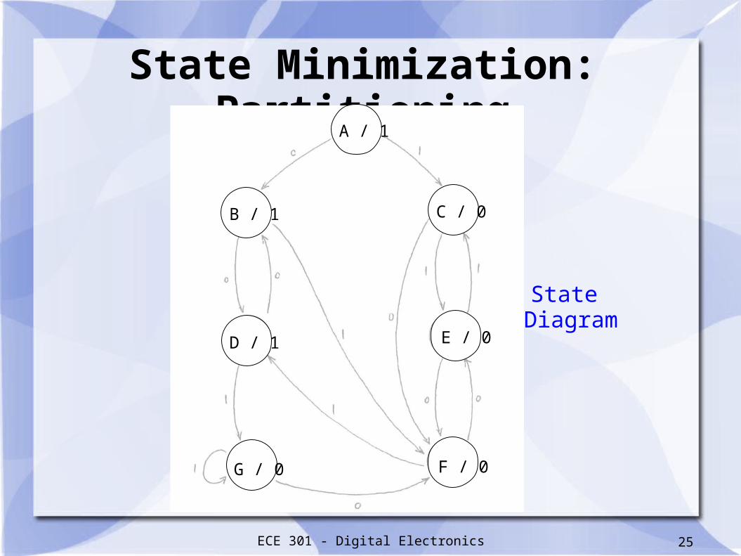
Example:
Use partitioning to minimize the number of states in the following Finite State Machine (FSM).
State Minimization: Partitioning
ECE 301 - Digital Electronics 25
State Minimization: Partitioning
State Diagram
G / 0 F / 0
E / 0D / 1
B / 1 C / 0
A / 1
ECE 301 - Digital Electronics 26
State Minimization: Partitioning
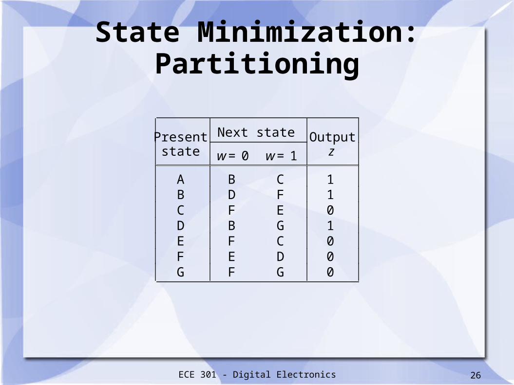
Present Next state Outputstate w = 0 w = 1 z
A B C 1 B D F 1 C F E 0 D B G 1 E F C 0 F E D 0 G F G 0
ECE 301 - Digital Electronics 27
State Minimization: Partitioning
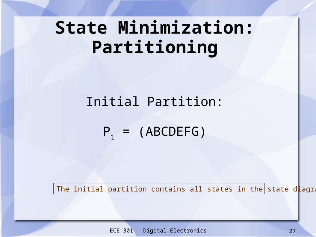
Initial Partition:
P1 = (ABCDEFG)
The initial partition contains all states in the state diagram / table.
ECE 301 - Digital Electronics 28
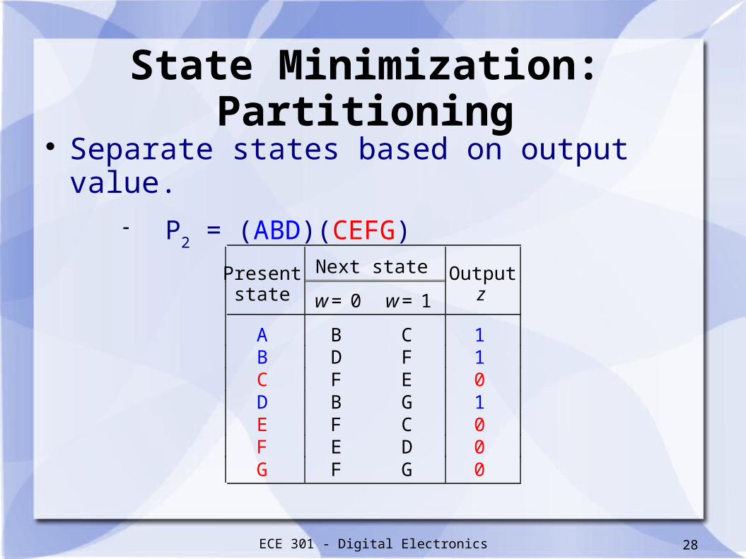
State Minimization: Partitioning
Present Next state Outputstate w = 0 w = 1 z
A B C 1 B D F 1 C F E 0 D B G 1 E F C 0 F E D 0 G F G 0
Separate states based on output value. P
2 = (ABD)(CEFG)
ECE 301 - Digital Electronics 29
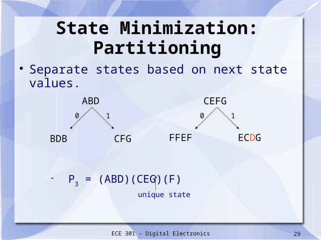
State Minimization: Partitioning
Separate states based on next state values.
P3 = (ABD)(CEG)(F)
ABD CEFG
BDB CFG FFEF ECDG
0 1 0 1
unique state

ECE 301 - Digital Electronics 30
State Minimization: Partitioning
Separate states based on next state values.
P4 = (AD)(CEG)(F)(B)
ABD CEG
BDB CFG FFF ECG
0 1 0 1
unique states
ECE 301 - Digital Electronics 31
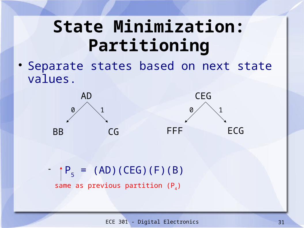
State Minimization: Partitioning
Separate states based on next state values.
P5 = (AD)(CEG)(F)(B)
AD CEG
BB CG FFF ECG
0 1 0 1
same as previous partition (P4)

ECE 301 - Digital Electronics 32
State Minimization: Partitioning Since P
4 = P
5, state minimization is complete.
The equivalent states are: A = D C = E = G B F
Thus, the FSM can be realized with just 4 states.

ECE 301 - Digital Electronics 33
FSM: State Minimization
Present Next state Outputstate w = 0 w = 1 z
A B C 1 B A F 1 C F C 0 F C A 0
Minimized State Table

ECE 301 - Digital Electronics 34
FSM: State Minimization
Minimized State Diagram

ECE 301 - Digital Electronics 35
Acknowledgments
The slides used in this lecture were taken, with permission, from those provided by McGraw-Hill for
Fundamentals of Digital Logic with VHDL Design (3rd Edition).
They are the property of and are copyrighted by McGraw-Hill Higher Education.
Recommended

![Sequential unconstrained minimization algorithms for constrained …faculty.uml.edu/cbyrne/summa2.pdf · 2008. 1. 10. · sequential unconstrained minimization algorithms [15]. We](https://img.pdfslide.net/doc/110x75/611fc7373f6d994a6c4a2ffa/sequential-unconstrained-minimization-algorithms-for-constrained-2008-1-10.jpg)