ECE C03 Lecture 16 1
Lecture 16Introduction to VHDL
Prith Banerjee
ECE C03
Advanced Digital Design
Spring 1998

ECE C03 Lecture 16 2
Outline
• VHDL Language Basics• Interface• Architecture Body• Behavioral VHDL• Various Sequential Statements• Process Statements• Delay Models• READING: Dewey 11.2, 11.3, 11.4, 11.5. 11.6, 15.1,
15.2, 18.2, 18.3, 18.4, 18.5
ECE C03 Lecture 16 3
Modeling Digital Systems
• Digital system: Any digital circuit that processes or stores information in digital form: gates to functional units
• Model represents only relevant information and abstracts away irrelevant detail
• Model needed to:– Develop and specify requirements– Communicate understanding of a system to a user– Allow testing of design through simulation– Allow formal verification– Allow automated synthesis
ECE C03 Lecture 16 4
What is VHDL
• (Very High Speed Integrated Circuits) VHSIC Hardware Description Language
• Used for two things– (1) Used to model digital systems, designs can then be
SIMULATED• A simulator runs a VHDL description computing the outputs of a modeled
system
– (2) Used as a language to enter designs into CAD tools, designs can then be SYNTHESIZED
• VHDL also provides a blackboard for designing digital systems
• An initial design is progressively expanded and refined
• Another popular hardware language is Verilog

ECE C03 Lecture 16 5
Relationship between VHDL and hardware
Model
VHDL description
Simulator
Simulated / actual outputs
Hardware

ECE C03 Lecture 16 6
Domains and Level of Modeling
FunctionalStructural
Geometric
Polygons
Algorithm
Register Transfer Level
Boolean Equation
Floorplan
Register transfer
Gates
Transistor
Standard Cells

ECE C03 Lecture 16 7
VHDL Modeling Concepts
• VHDL Includes facilities for describing the FUNCTION and STRUCTURE
• At Various levels from abstract to the gate level• Intended as a modeling language for specification
and simulation• Also used for synthesis

ECE C03 Lecture 16 8
Example of VHDL DescriptionVHDL Model of a 2input exclusive OR gate
entity XOR2_OP is
-- input output ports
port
(A, B : in BIT;
Z : out BIT);
-- Body
architecture EX_DISJUNCTION of XOR_OP2 is
begin
Z <= A xor B;
end EX_DISJUNCTION;
ECE C03 Lecture 16 9
VHDL Entity Definitions
• A VHDL entity consists of two parts:– interface denoted by keyword “entity”– body denoted by keyword “architecture”
• Interface describes aspects visible outside
• Body describes how black box operates inside
• FORMAT:
entity identifier is
port (name: in / out / inout BIT/type);
end identifier;
-- lines beginning with two dashes are comments
ECE C03 Lecture 16 10
VHDL Architecture Body
• Architecture body describes how entity operates
• Allows for different implementations
• Can have behavioral or structural or mixed representations
FORMAT
architecture EX_DISJUNCTION of XOR_OP2 is
begin
Z <= A xor B;
end EX_DISJUNCTION;
ECE C03 Lecture 16 11
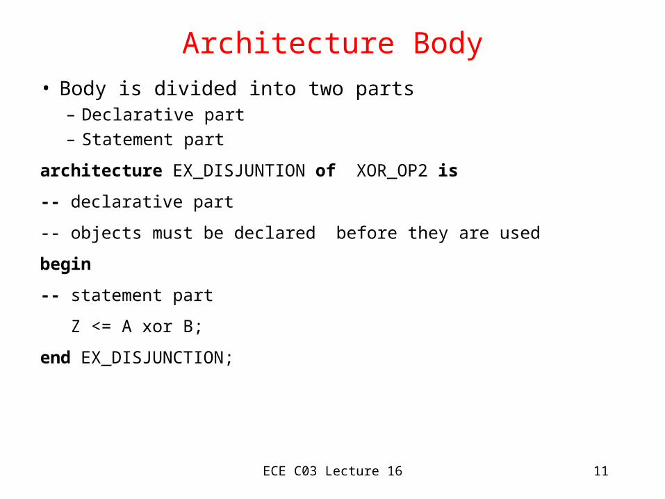
Architecture Body
• Body is divided into two parts– Declarative part– Statement part
architecture EX_DISJUNTION of XOR_OP2 is
-- declarative part
-- objects must be declared before they are used
begin
-- statement part
Z <= A xor B;
end EX_DISJUNCTION;

ECE C03 Lecture 16 12
Data Types in VHDL
• The type of a data object defines the set of values that object can assume and set of operations on those values – VHDL is a strongly typed language
• Four classes of objects– constants
– variables
– signals
– files

ECE C03 Lecture 16 13
Constant Declaration
• The value of a constant cannot be changed• FORMAT:
constant identifier {, } : subtype [ := expression]• EXAMPLES:
constant number_of_bytes : integer := 4;
constant prop_delay : time := 3nsec;
constant e : real := 2.2172;

ECE C03 Lecture 16 14
Variable Declaration
• The value of a variable can be changed• FORMAT
variable identifier {, ..} subtype [ := expression]• EXAMPLES
variable index: integer := 0;
variable sum, average, largest : real;
variable start, finish : time : = 0 nsec;

ECE C03 Lecture 16 15
Variable Assignment Statement• Once a variable is declared, its value can be modified by an
assignment statement• FORMAT:
[ label : ] name := expression;• EXAMPLES:
program_counter := 0;
index := index + 1;• Variable assignment different from signal assignment
– A variable assignment immediately overviews variable with new value– A signal assignment schedules new value at later time

ECE C03 Lecture 16 16
Scalar Types
• Variable can only assign values of nominated type• Default types
– “integer” , “real”, “character,” “boolean”, “bit”
• User defined types– FORMAT:
type small_int is range 0 to 255;
• Enumerated type:– FORMAT:
type logiclevel is (unknown, low, driven, high);
ECE C03 Lecture 16 17
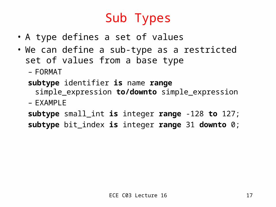
Sub Types
• A type defines a set of values• We can define a sub-type as a restricted set of
values from a base type– FORMAT
subtype identifier is name range simple_expression to/downto simple_expression
– EXAMPLE
subtype small_int is integer range -128 to 127;
subtype bit_index is integer range 31 downto 0;

ECE C03 Lecture 16 18
Attributes of Types• A type defines a set of values and set of applicable operations• A predefined set of attributes are used to give information about
the values included in the type• T’left = first (leftmost) value in T• T’right = last (righmost) value in T• T’value = the value in T that is represented by s• EXAMPLES:
type set_index_range is range 21 downto 11;
set_index_range’left = 21
set_index_range’right = 11
set_index_range’value(“20”) = 20

ECE C03 Lecture 16 19
Expressions and Operators
Operator Operation Operand Types** Exponentiation Integer, realAbs Absoluet value numeric*, / , mod, rem Mul, div Integer, realAnd, nand, or, nor, xor, xnor, not Logical ops Bit, boolean, or 1-D arraySll, srl, sla,sra Shift left/right 1-D array of bit/boolean+, - Add, subtract Integer, real=, /=, <, <=, >, >= Equal, greater Scalar

ECE C03 Lecture 16 20
Sequential Statements
• Sequential statements of various types are executed in sequence within each VHDL process
• Variable statementvariable := expression;
• If statement• Case statement• Loop statement

ECE C03 Lecture 16 21
If Statement• FORMAT
if boolean_expression then
{sequential statement}
elsif boolean_expression then
{sequential statement}
else {sequential statement}
endif;• EXAMPLE
if sel=0 then
result <= input_0; -- executed if sel = 0
else result <= input_1; -- executed if sel = 1
endif;

ECE C03 Lecture 16 22
Case Statement• EXAMPLE of an ALU operation:
case func is
when pass1 =>
result := operand1;
when pass2 =>
result := operand2;
when add =>
result := operand1 + operand2;
when subtract =>
result := operand1 - operand2;
end case;
ECE C03 Lecture 16 23
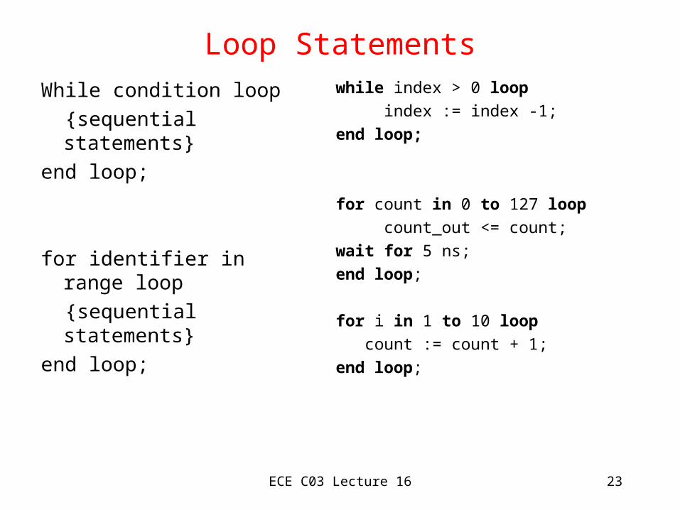
Loop Statements
While condition loop
{sequential statements}
end loop;
for identifier in range loop
{sequential statements}
end loop;
while index > 0 loop
index := index -1;
end loop;
for count in 0 to 127 loop
count_out <= count;
wait for 5 ns;
end loop;
for i in 1 to 10 loop
count := count + 1;
end loop;

ECE C03 Lecture 16 24
Concurrent Statements
• The concurrent statement in an architecture body describe the module’s operation.– Concurrency is useful in modeling the way real circuits behave
architecture abstract of adder is
begin
add_a_b : process(a,b) is
begin
sum <= a + b;
end process add_a_b;
end architecture abstract;
ECE C03 Lecture 16 25
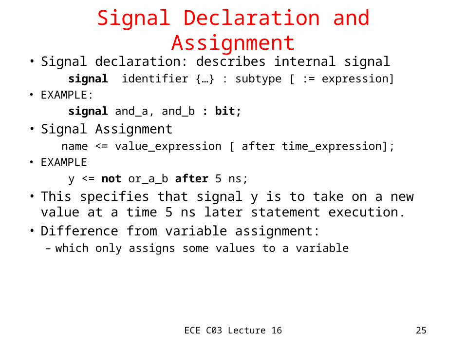
Signal Declaration and Assignment• Signal declaration: describes internal signal signal identifier {…} : subtype [ := expression]• EXAMPLE:
signal and_a, and_b : bit;
• Signal Assignment name <= value_expression [ after time_expression];• EXAMPLE
y <= not or_a_b after 5 ns;
• This specifies that signal y is to take on a new value at a time 5 ns later statement execution.
• Difference from variable assignment:– which only assigns some values to a variable

ECE C03 Lecture 16 26
Concepts of Delays and Timing
• The time dimension in the signal assignment refers to simulation time in a discrete event simulation
• There is a simulation time clock• When a signal assignment is executed, the delay
specified is added to current simulation time to determine when new value is applied to signal– Schedules a transaction for the signal at that time
input
output

ECE C03 Lecture 16 27
Specifying Technology Information• One predefined physical type in VHDL: TIME
• Units: fs (10** -15 seconds), ps (1000 fs), ns, us, ms, sec, min ( 60 sec), hr (60 min)
• User-defined physical typestype CAPACITANCE is range 0 to INTEGER’HIGH
units
fF; -- Femtofarads
pF = 1000 fF; -- Picofarads
nF = 1000 pF; -- Nanofarads
end units
type VOLTAGE is range 0 to 2 ** 32 -1
units
uV; -- Microvolt;
mV = 1000 uV;
V = 1000 mV;
end units;

ECE C03 Lecture 16 28
Specifying Delays
• Inertial Delay Model– reflects physical inertia of physical systems
– glitches of very small duration not reflected in outputs
• SIG_OUT <= not SIG_IN after 7 nsec --implicit• SIG_OUT <= inertial ( not SIG_IN after 7 nsec )• Logic gates exhibit lowpass filtering
SIG_IN
SIG_OUT2ns
9 ns 19 ns
3 ns10ns

ECE C03 Lecture 16 29
Transport Delays
• Under this model, ALL input signal changes are reflected at the output
• SIG_OUT <= transport not SIG_IN after 7 ns;
SIG_IN
SIG_OUT2ns
9 ns 19 ns
3 ns10ns
30 ns

ECE C03 Lecture 16 30
Example of Architecture Body(AND_OR_INVERT)
architecture primitive of and_or_inv is
signal and_a, and_b, or_a_b : bit;
begin
and_gate_a : process (a1,a2) is
begin
and_a <= a1 and a2;
end process and_gate_a;
and_gate_b : process (b1,b2) is
begin
and_b <= b1 and b2;
end process and_gate_b;
or_gate: process (and_a, and_b) is
begin
or_a_b <= and_a or and_b;
end process or_gate;
inv : process (or_a_b) is
begin
y <= not or_a_b;
end process inv;
end architecture primitive;a1a2
b1b2
y

ECE C03 Lecture 16 31
Process Declaration of Clock Generator
Clock_gen: process (clk) is
begin
if clk = ‘0’ then
clk <= ‘1’ after T_pw, ‘0’ after 2*T_pw;
endif;
end process clock_gen;T_pw
2*T_pw

ECE C03 Lecture 16 32
Process Generator for Multiplexer
a
b
sel
z
mux: process (a, b, sel) is
begin
case sel is
when ‘0’ =>
z <= a after prop_delay;
when ‘1’ =>
z <= b after prop_delay;
end process mux;

ECE C03 Lecture 16 33
Wait Statement
• A wait statement specifies how a process responds to changes in signal values.
wait on signal_name
wait until boolean_expression
wait for time_expression• Example on right shows process sensitivity list
EXAMPLE: SAME AS:half_add: process isbegin sum <= a xor b after T_pd; carry <= a and b after T_pd; wait on a, b;end process;
half_add: process (a,b) isbegin sum <= a xor b after T_pd; carry <= a and b after T_pd;end process;

ECE C03 Lecture 16 34
Process Statement
• A process statement is a concurrent statement that can be included in an architecture body to describe all or part of the behavior of a module.
FORMAT:process [ (signal_name, …) ] is
process_declarative item
begin
{ sequential statement;}
end process;
ECE C03 Lecture 16 35
Summary
• VHDL Language Basics
• Interface
• Architecture Body
• Behavioral VHDL
• Various Sequential Statements
• Process Statements
• Delay Models
• NEXT LECTURE: VHDL Structural and Mixed Description
• READING: Dewey 12.1, 12.2, 12.3, 12.4, 13.1, 13.2, 13.3. 13.4, 13.6, 13.7. 13.8
Recommended