

www.ATIcourses.com
Boost Your Skills with On-Site Courses Tailored to Your Needs The Applied Technology Institute specializes in training programs for technical professionals. Our courses keep you current in the state-of-the-art technology that is essential to keep your company on the cutting edge in today’s highly competitive marketplace. Since 1984, ATI has earned the trust of training departments nationwide, and has presented on-site training at the major Navy, Air Force and NASA centers, and for a large number of contractors. Our training increases effectiveness and productivity. Learn from the proven best. For a Free On-Site Quote Visit Us At: http://www.ATIcourses.com/free_onsite_quote.asp For Our Current Public Course Schedule Go To: http://www.ATIcourses.com/schedule.htm
Copyright 1996-‐2015 Erevno Aerospace
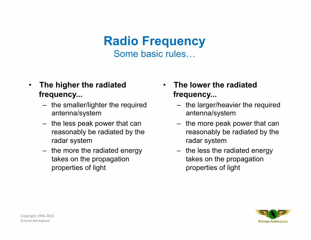
• The higher the radiated frequency... – the smaller/lighter the required
antenna/system – the less peak power that can
reasonably be radiated by the radar system
– the more the radiated energy takes on the propagation properties of light
• The lower the radiated frequency... – the larger/heavier the required
antenna/system – the more peak power that can
reasonably be radiated by the radar system
– the less the radiated energy takes on the propagation properties of light
Radio Frequency Some basic rules…
Copyright 1996-‐2015 Erevno Aerospace
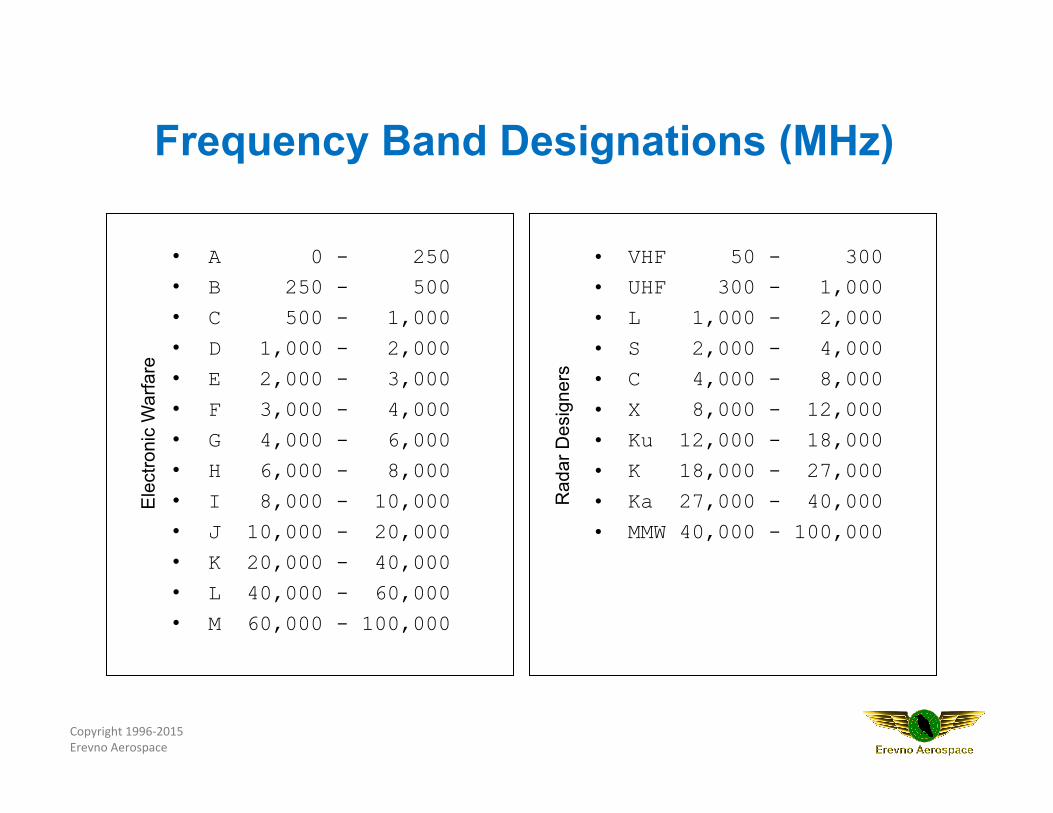
• A 0 - 250 • B 250 - 500
• C 500 - 1,000
• D 1,000 - 2,000
• E 2,000 - 3,000
• F 3,000 - 4,000
• G 4,000 - 6,000
• H 6,000 - 8,000
• I 8,000 - 10,000
• J 10,000 - 20,000
• K 20,000 - 40,000
• L 40,000 - 60,000
• M 60,000 - 100,000
• VHF 50 - 300 • UHF 300 - 1,000
• L 1,000 - 2,000
• S 2,000 - 4,000
• C 4,000 - 8,000
• X 8,000 - 12,000
• Ku 12,000 - 18,000
• K 18,000 - 27,000
• Ka 27,000 - 40,000
• MMW 40,000 - 100,000
Ele
ctro
nic
War
fare
Rad
ar D
esig
ners
Frequency Band Designations (MHz)
Copyright 1996-‐2015 Erevno Aerospace
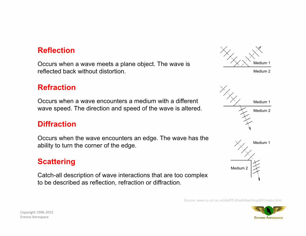
Reflection Occurs when a wave meets a plane object. The wave is reflected back without distortion. Refraction Occurs when a wave encounters a medium with a different wave speed. The direction and speed of the wave is altered. Diffraction Occurs when the wave encounters an edge. The wave has the ability to turn the corner of the edge. Scattering Catch-all description of wave interactions that are too complex to be described as reflection, refraction or diffraction.
Source: www.cs.ucl.ac.uk/staff/S.Bhatti/teaching/d51/notes.html
Medium 1
Medium 2
Medium 1
Medium 2
Medium 1
Medium 2
Copyright 1996-‐2015 Erevno Aerospace
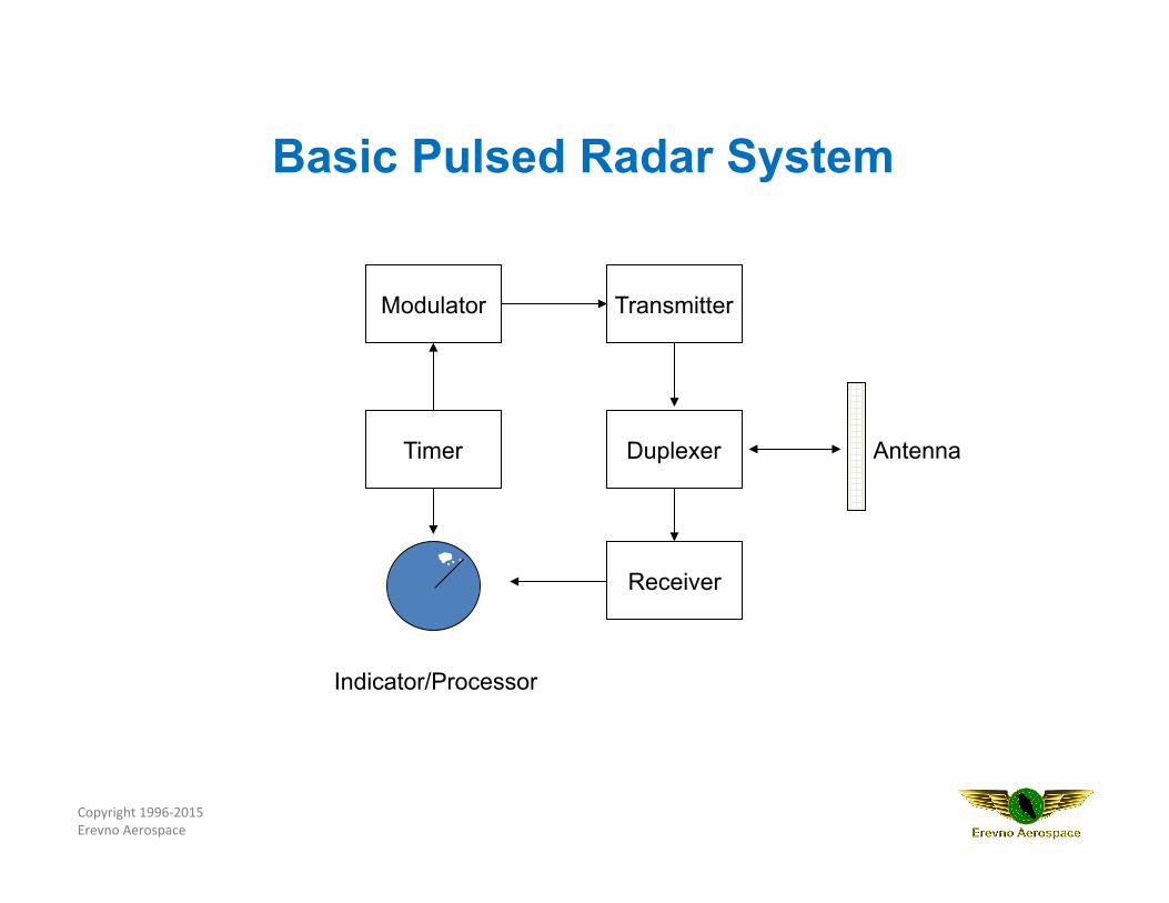
Transmitter
Timer
Modulator
Duplexer Antenna
Indicator/Processor
Receiver
Basic Pulsed Radar System
Copyright 1996-‐2015 Erevno Aerospace
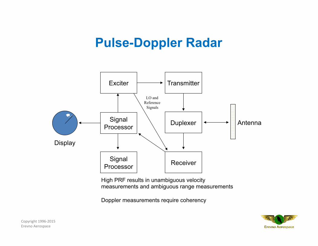
Transmitter Exciter
Duplexer Antenna
Display
Receiver Signal Processor
Signal Processor
High PRF results in unambiguous velocity measurements and ambiguous range measurements Doppler measurements require coherency
LO and Reference
Signals
Pulse-Doppler Radar
Copyright 1996-‐2015 Erevno Aerospace
Pulse Repetition Interval (PRI)
Pulse Repetition Frequency
(PRF)
Pulse Duration (PD)
The Pulse Train
Copyright 1996-‐2015 Erevno Aerospace
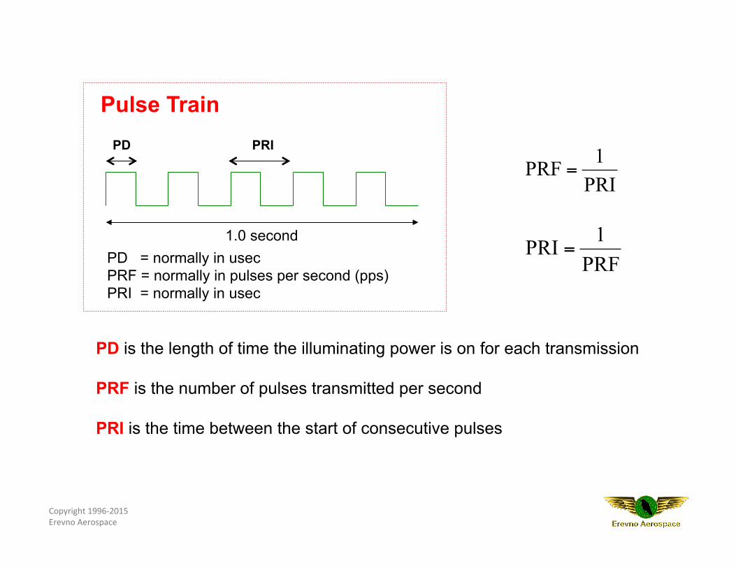
PRF1PRI =
PRI1PRF =
PD = normally in usec PRF = normally in pulses per second (pps) PRI = normally in usec
1.0 second
PD PRI
Pulse Train
PD is the length of time the illuminating power is on for each transmission PRF is the number of pulses transmitted per second PRI is the time between the start of consecutive pulses
Copyright 1996-‐2015 Erevno Aerospace
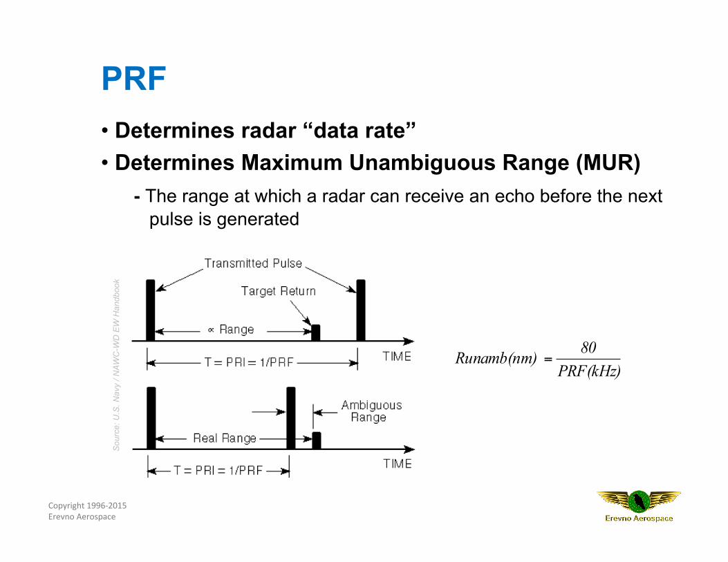
PRF(kHz)80Runamb(nm) =
PRF • Determines radar “data rate” • Determines Maximum Unambiguous Range (MUR)
- The range at which a radar can receive an echo before the next pulse is generated
Sou
rce:
U.S
. Nav
y / N
AWC
-WD
EW
Han
dboo
k
Copyright 1996-‐2015 Erevno Aerospace
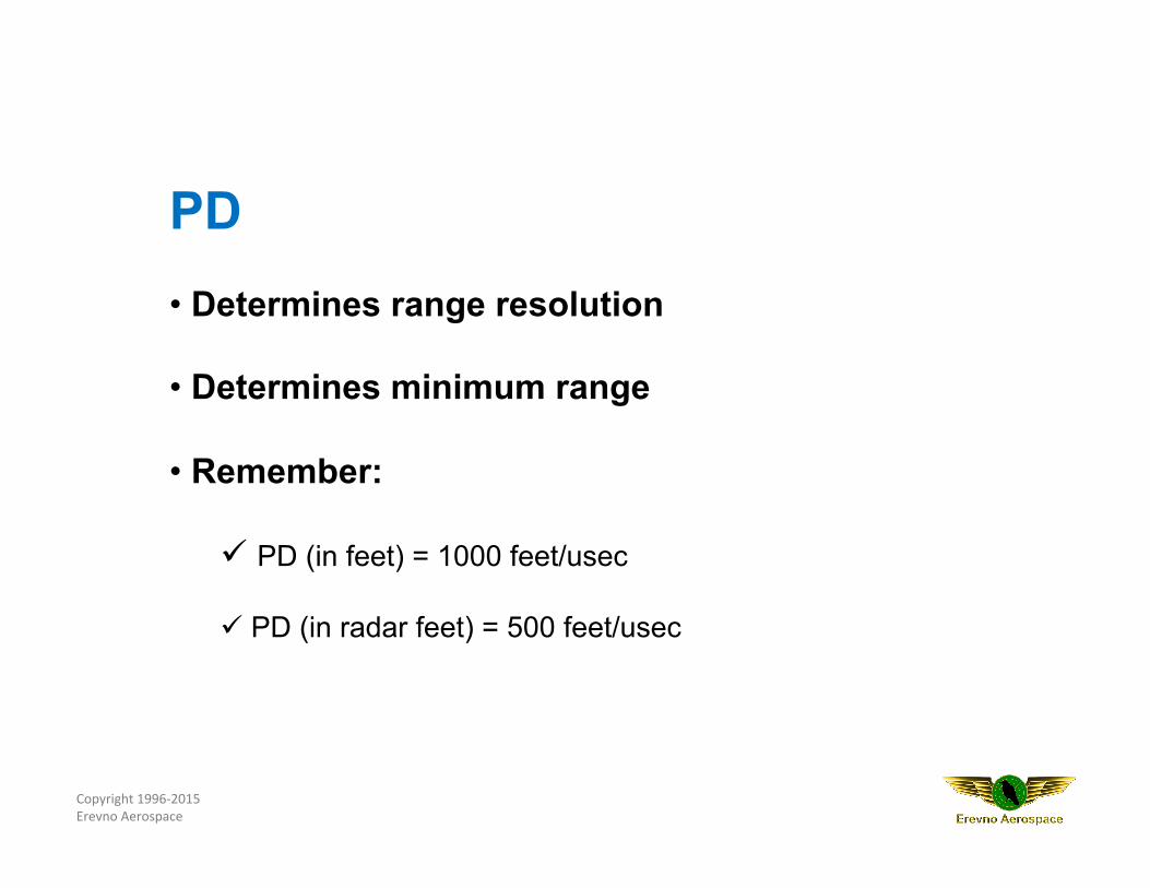
PD • Determines range resolution
• Determines minimum range
• Remember:
ü PD (in feet) = 1000 feet/usec ü PD (in radar feet) = 500 feet/usec
Copyright 1996-‐2015 Erevno Aerospace
Variation of interval between pulses within the radar’s pulse train
Used to eliminate MTI blind speeds,
main-bang eclipsing and range ambiguities
Improves anti-jamming (EP) capabilities
Interpulse Modulation
Copyright 1996-‐2015 Erevno Aerospace
Involves the process of modulating the RF carrier of a pulsed radar during transmission (within the pulse)
Pulses can vary in frequency, phase or amplitude
Increases range and range resolution
Example: Pulse Compression
Intrapulse Modulation
Copyright 1996-‐2015 Erevno Aerospace
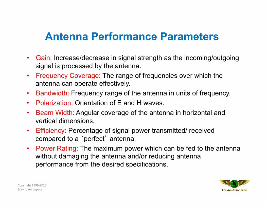
• Gain: Increase/decrease in signal strength as the incoming/outgoing signal is processed by the antenna.
• Frequency Coverage: The range of frequencies over which the antenna can operate effectively.
• Bandwidth: Frequency range of the antenna in units of frequency. • Polarization: Orientation of E and H waves. • Beam Width: Angular coverage of the antenna in horizontal and
vertical dimensions. • Efficiency: Percentage of signal power transmitted/ received
compared to a ‘perfect’ antenna. • Power Rating: The maximum power which can be fed to the antenna
without damaging the antenna and/or reducing antenna performance from the desired specifications.
Antenna Performance Parameters
Copyright 1996-‐2015 Erevno Aerospace
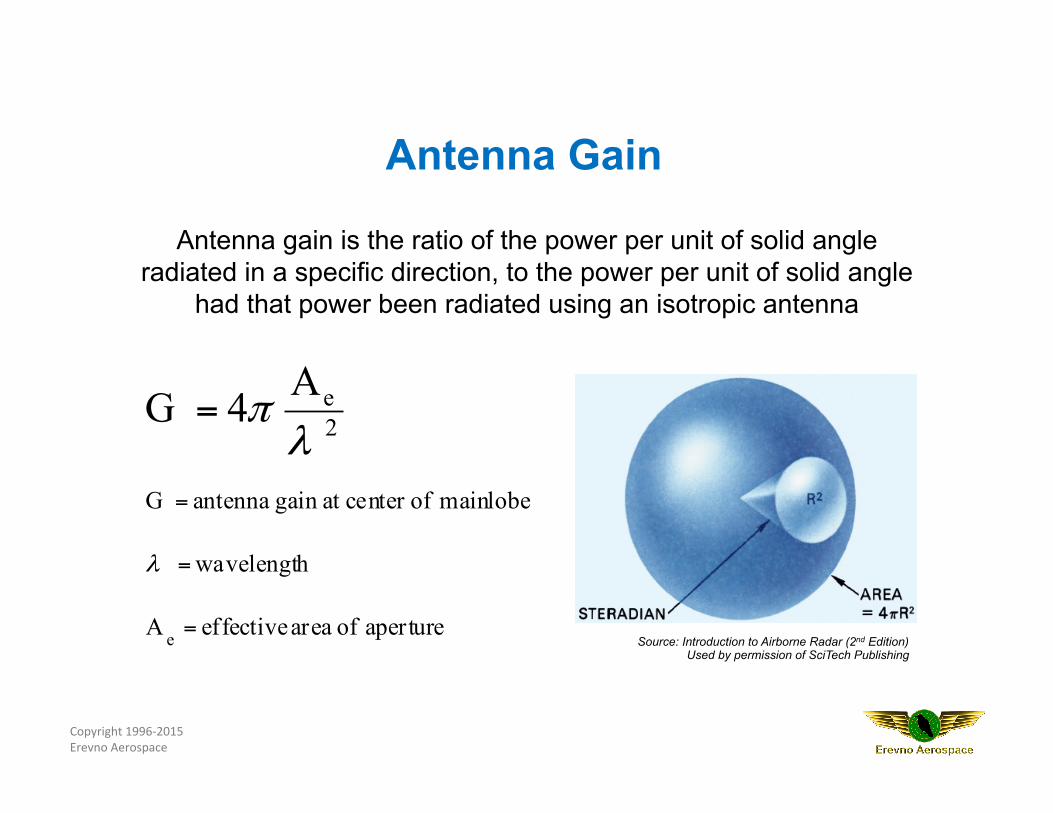
Antenna gain is the ratio of the power per unit of solid angle radiated in a specific direction, to the power per unit of solid angle
had that power been radiated using an isotropic antenna
aperture of area effective A
h wavelengt
mainlobe ofcenter at gain antenna G
2e
e
A 4 G
=
=
=
=
λ
λπ
Source: Introduction to Airborne Radar (2nd Edition) Used by permission of SciTech Publishing
Antenna Gain
Copyright 1996-‐2015 Erevno Aerospace
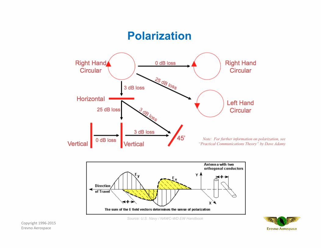
Polarization
Note: For further information on polarization, see “Practical Communications Theory” by Dave Adamy
Source: U.S. Navy / NAWC-WD EW Handbook
Copyright 1996-‐2015 Erevno Aerospace
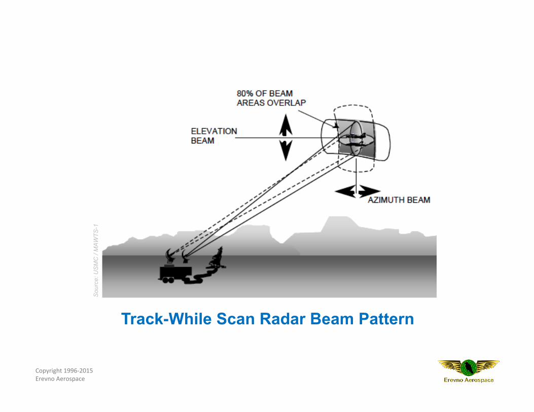
Sou
rce:
US
MC
/ M
AWTS
-1
Track-While Scan Radar Beam Pattern
Copyright 1996-‐2015 Erevno Aerospace
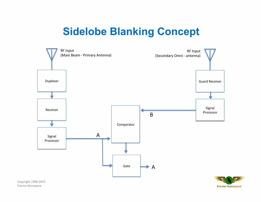
RF Input (Main Beam -‐ Primary Antenna)
RF Input (Secondary Omni -‐ antenna)
Comparator
Duplexer
Receiver
Signal Processor
Guard Receiver
Signal Processor
A
B
Gate A
Sidelobe Blanking Concept
Copyright 1996-‐2015 Erevno Aerospace
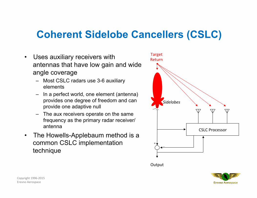
Coherent Sidelobe Cancellers (CSLC)
• Uses auxiliary receivers with antennas that have low gain and wide angle coverage
– Most CSLC radars use 3-6 auxiliary elements
– In a perfect world, one element (antenna) provides one degree of freedom and can provide one adaptive null
– The aux receivers operate on the same frequency as the primary radar receiver/ antenna
• The Howells-Applebaum method is a common CSLC implementation technique
CSLC Processor
Output
Sidelobes
Target Return
+ -‐
Copyright 1996-‐2015 Erevno Aerospace
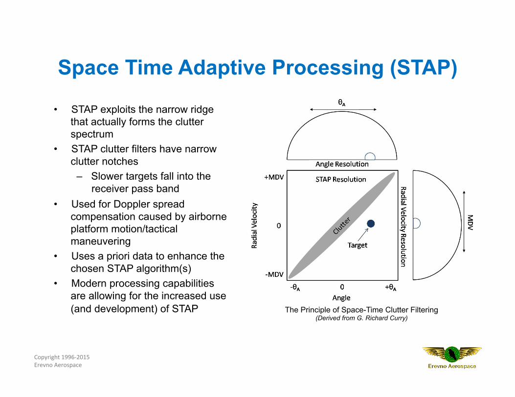
Space Time Adaptive Processing (STAP)
• STAP exploits the narrow ridge that actually forms the clutter spectrum
• STAP clutter filters have narrow clutter notches
– Slower targets fall into the receiver pass band
• Used for Doppler spread compensation caused by airborne platform motion/tactical maneuvering
• Uses a priori data to enhance the chosen STAP algorithm(s)
• Modern processing capabilities are allowing for the increased use (and development) of STAP The Principle of Space-Time Clutter Filtering
(Derived from G. Richard Curry)
Copyright 1996-‐2015 Erevno Aerospace
Knowledge-Based (KB) Radar Systems
• KB radar systems can dynamically change processing when provided with data from various sources – Processing power was the inhibiter in the past (no longer the case)
• KB-STAP now possible – Artificial intelligence (AI) methods can be used to dynamically
choose the best STAP algorithm based upon programmable factors, vice a set (single) algorithm based upon a priori data
• AI has been used to develop an expert system to dynamically modify CFAR
• Use of KB techniques to perform filtering, detection, tracking and target identification is ongoing – NATO has held conferences on KB radar
Copyright 1996-‐2015 Erevno Aerospace
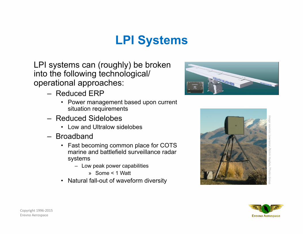
LPI Systems
LPI systems can (roughly) be broken into the following technological/ operational approaches:
– Reduced ERP • Power management based upon current
situation requirements – Reduced Sidelobes
• Low and Ultralow sidelobes – Broadband
• Fast becoming common place for COTS marine and battlefield surveillance radar systems
– Low peak power capabilities » Some < 1 Watt
• Natural fall-out of waveform diversity
Image sources: Low
rance /Kelvin Hughes /Thales Group
Copyright 1996-‐2015 Erevno Aerospace
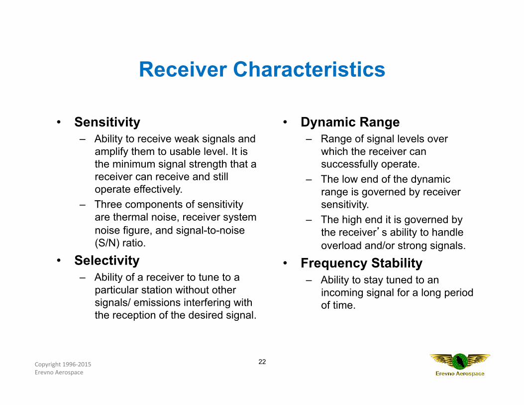
• Sensitivity – Ability to receive weak signals and
amplify them to usable level. It is the minimum signal strength that a receiver can receive and still operate effectively.
– Three components of sensitivity are thermal noise, receiver system noise figure, and signal-to-noise (S/N) ratio.
• Selectivity – Ability of a receiver to tune to a
particular station without other signals/ emissions interfering with the reception of the desired signal.
• Dynamic Range – Range of signal levels over
which the receiver can successfully operate.
– The low end of the dynamic range is governed by receiver sensitivity.
– The high end it is governed by the receiver’s ability to handle overload and/or strong signals.
• Frequency Stability – Ability to stay tuned to an
incoming signal for a long period of time.
22
Receiver Characteristics
Copyright 1996-‐2015 Erevno Aerospace
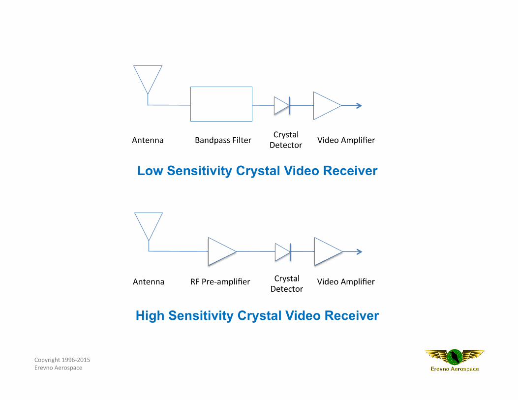
Low Sensitivity Crystal Video Receiver
High Sensitivity Crystal Video Receiver
RF Pre-‐amplifier Crystal Detector
Video Amplifier Antenna
Antenna Bandpass Filter Crystal Detector Video Amplifier
Copyright 1996-‐2015 Erevno Aerospace
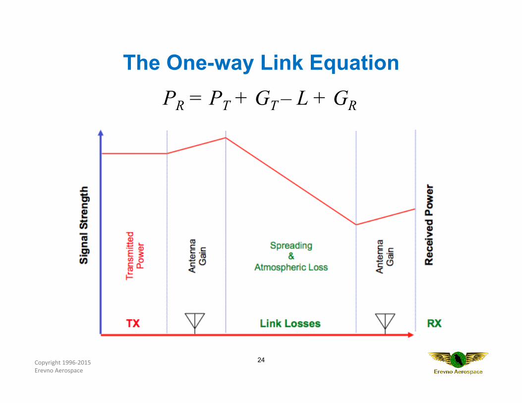
PR = PT + GT – L + GR
24
The One-way Link Equation
Copyright 1996-‐2015 Erevno Aerospace
25
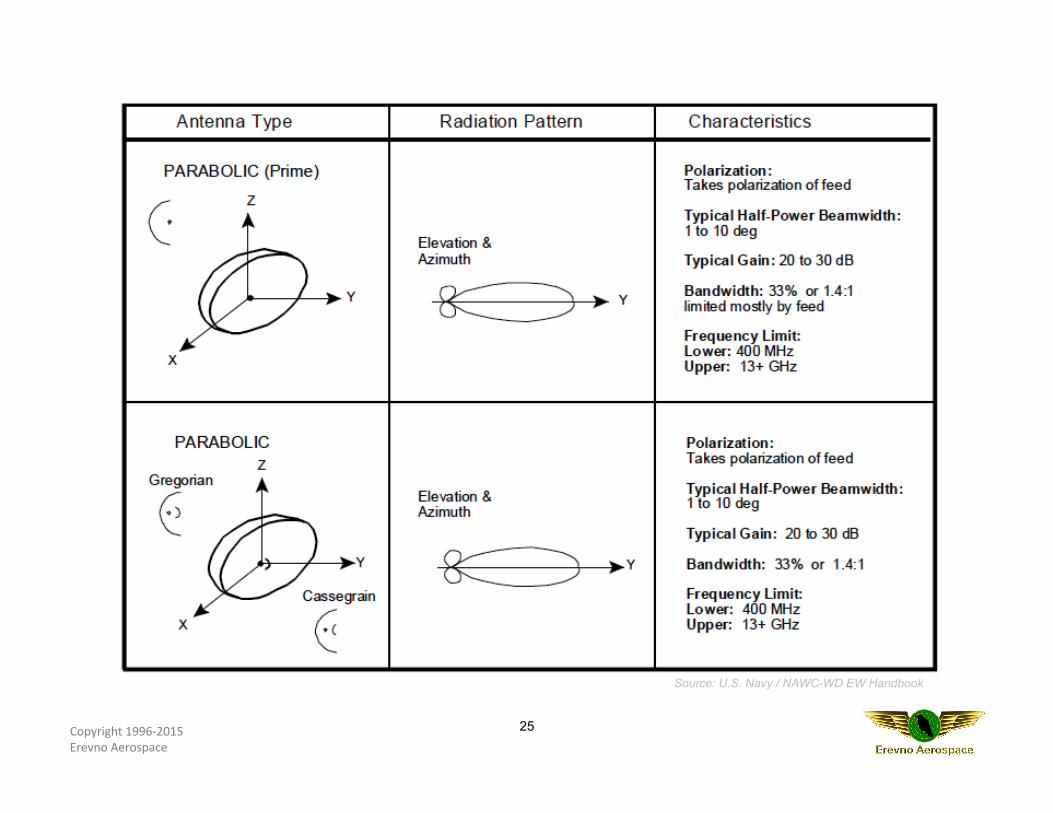
Source: U.S. Navy / NAWC-WD EW Handbook
Copyright 1996-‐2015 Erevno Aerospace
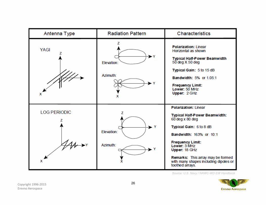
26
Source: U.S. Navy / NAWC-WD EW Handbook
Copyright 1996-‐2015 Erevno Aerospace
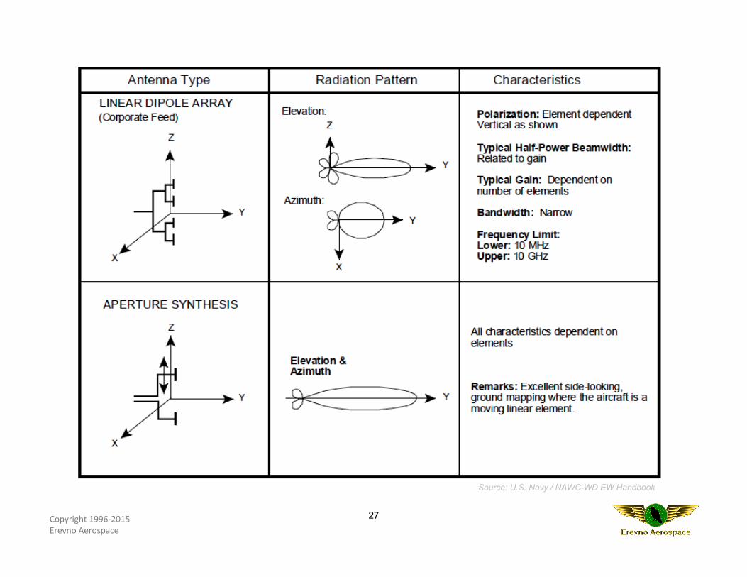
27
Source: U.S. Navy / NAWC-WD EW Handbook
Copyright 1996-‐2015 Erevno Aerospace
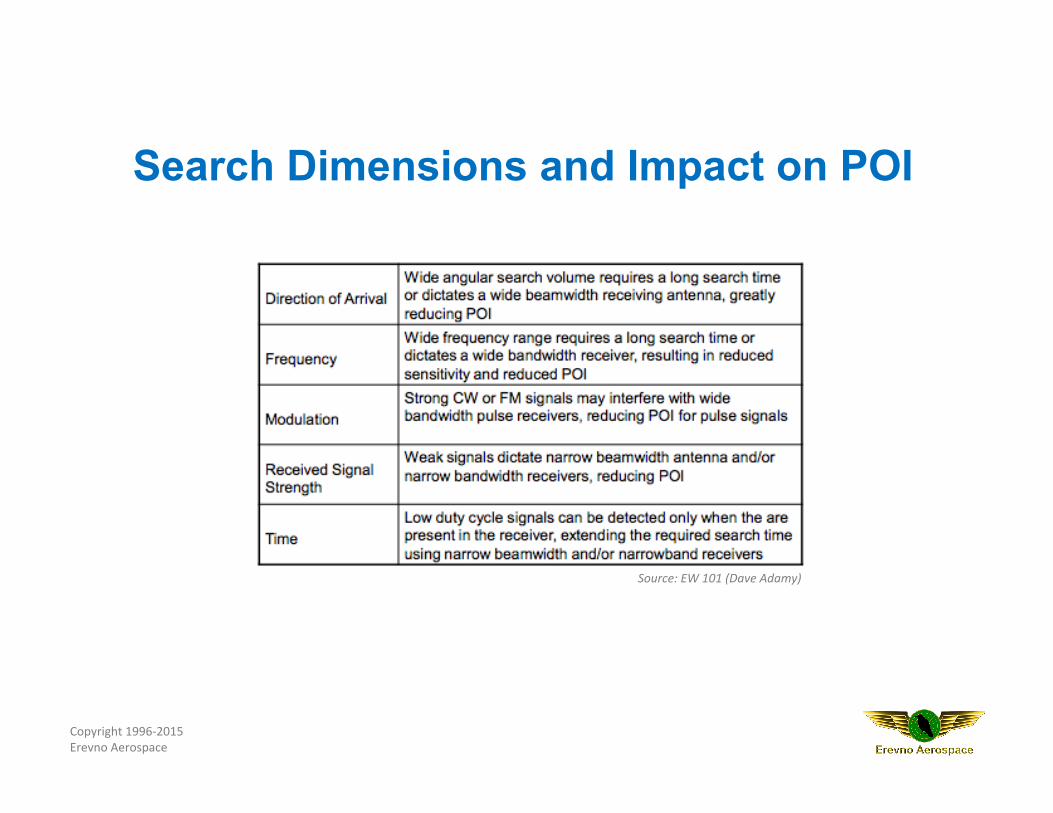
Search Dimensions and Impact on POI
Source: EW 101 (Dave Adamy)
Copyright 1996-‐2015 Erevno Aerospace
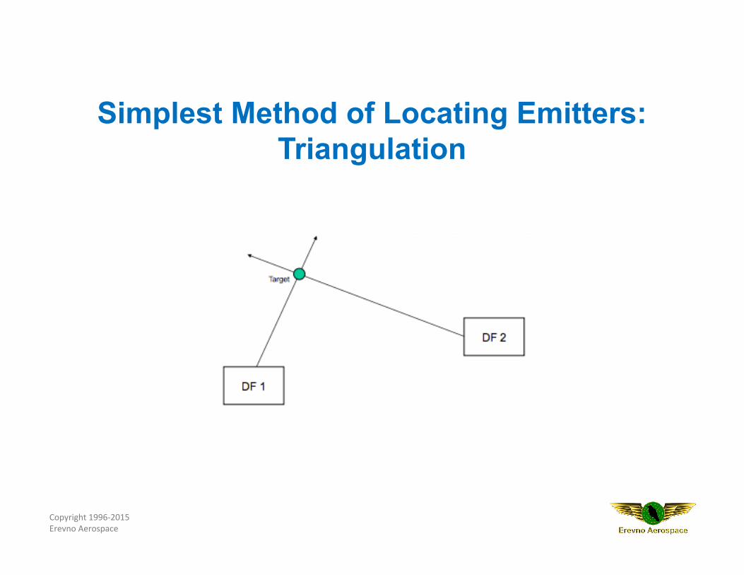
Simplest Method of Locating Emitters: Triangulation

To learn more please attend this ATI course
Please post your comments and questions to our blog:
http://www.aticourses.com/blog/index.php
Sign-up for ATI's monthly Course Schedule Updates:
http://app.streamsend.com/public/fIbq/cr5/subscribe
Recommended