TTF EMI/EMC Working Group Meeting 29/05/2006 H.Kapitza (FLA)
EMI Steering Group Report1. Epcos EMC Filter Seminar:
• On May 4, 2006 there was an EMC Filter Seminar held in the Novotel
HH-Schnelsen, organized by the Epcos company, the former passive
components branch of Siemens.
• The event was surprisingly neutral, with some very nice talks and good
documentation.
• Is there a problem to join such events?
2. Next meeting:
• Monday 10/07/06 at 11:00 here.
• Focus: Progress on today’s topics.
TTF EMI/EMC Working Group Meeting 29/05/2006 H.Kapitza (FLA)
XFEL Tunnel Grounding (2)
Topics:
1. Cross Section Update
2. Floor Inclusion
3. Mockup Tunnel
4. Next Steps
XFEL Facility Ground
• Due to its length >> λ(2 MHz)/10 = 15 m the XFEL facility needs a
hybrid ground system where many local single-point grounding areas are
connected to a common facility ground.
• In order to push its impedance as low as possible, the common facility
ground (plane) should include as much through-going metal structure as
possible (tubes, pipes, cable trays, remesh,. . .).
• Since these components will not really form a plane, aim at a mesh size
≈ λ(2 MHz)/50 = 3 m.
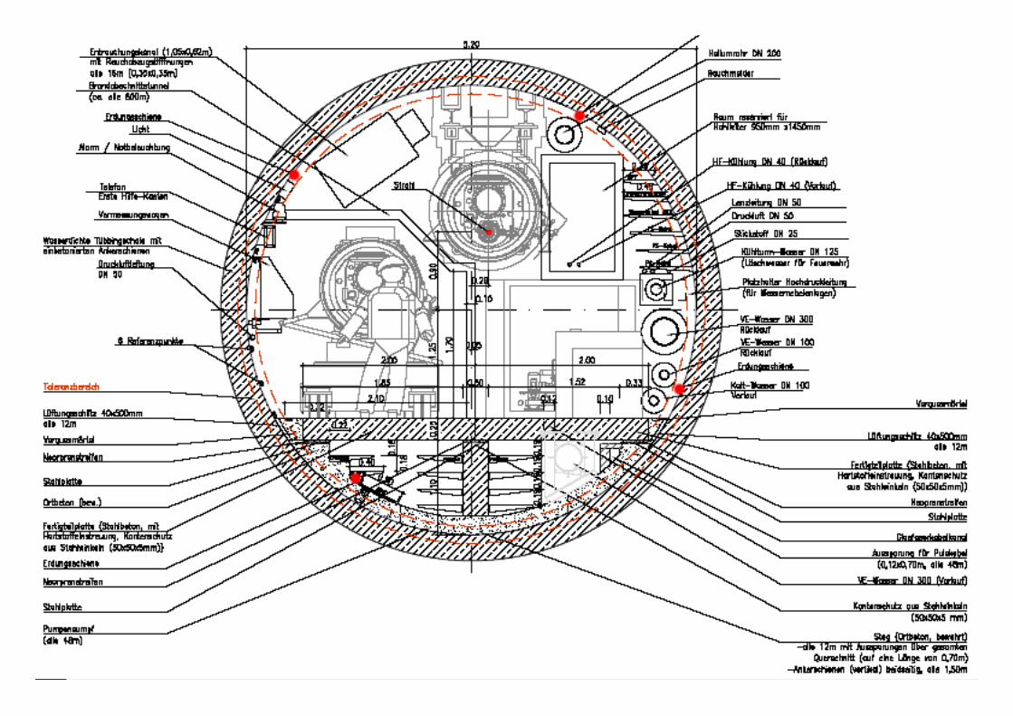
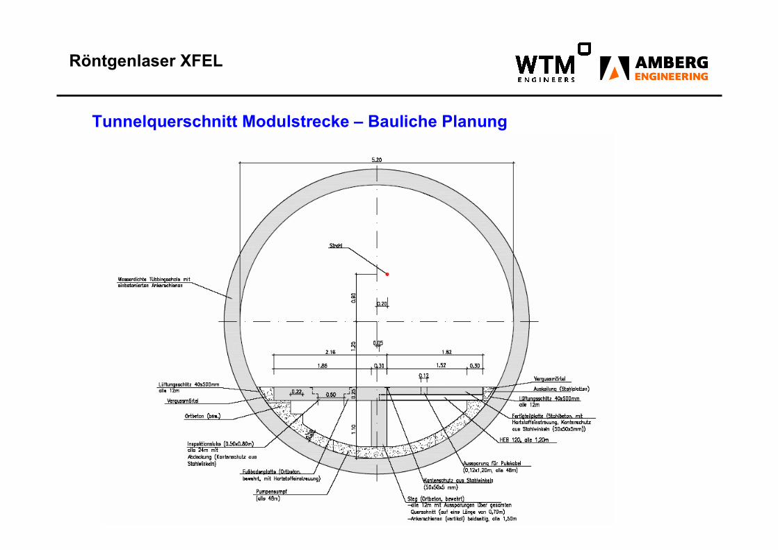
Röntgenlaser XFEL
Tunnelquerschnitt Modulstrecke – Bauliche Planung
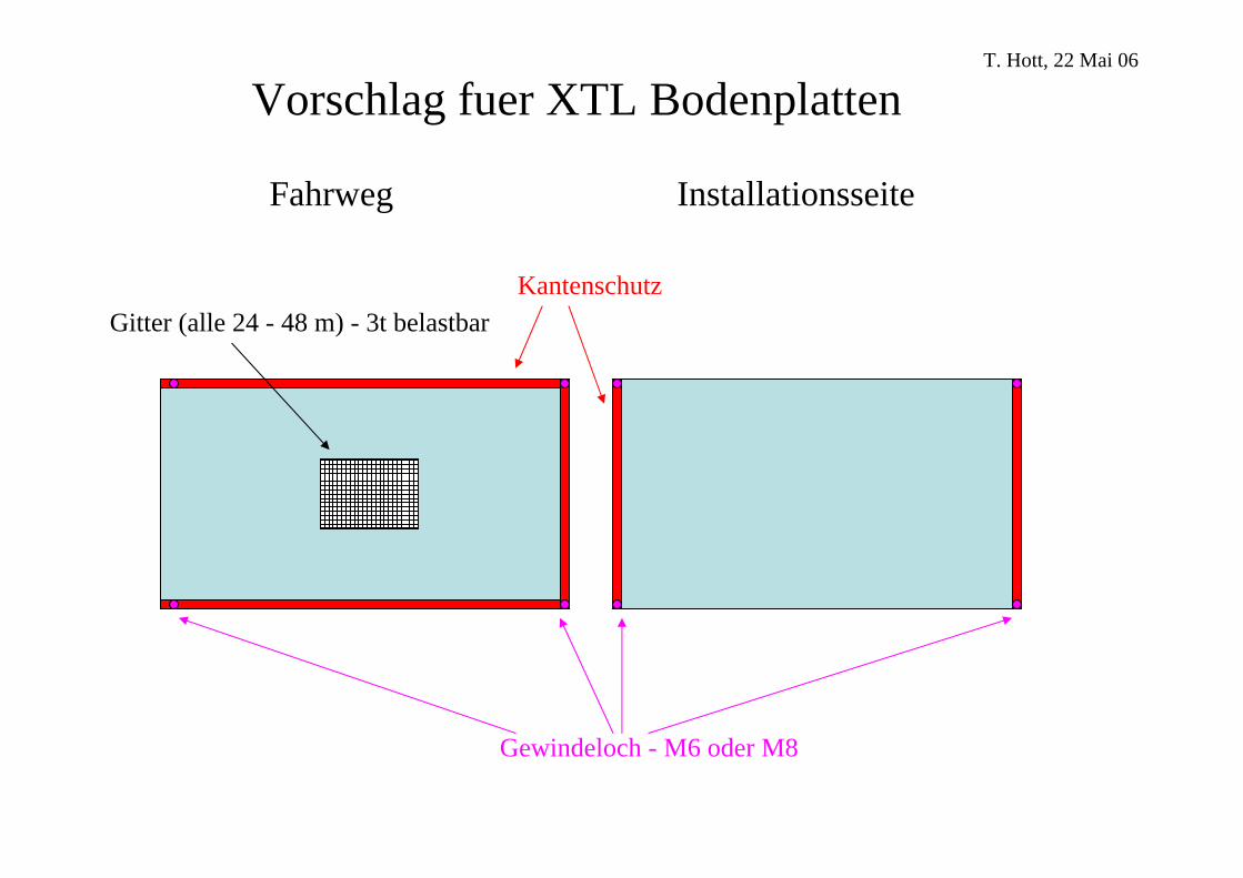
Vorschlag fuer XTL Bodenplatten
Kantenschutz
Gewindeloch - M6 oder M8
Gitter (alle 24 - 48 m) - 3t belastbar
Fahrweg Installationsseite
T. Hott, 22 Mai 06
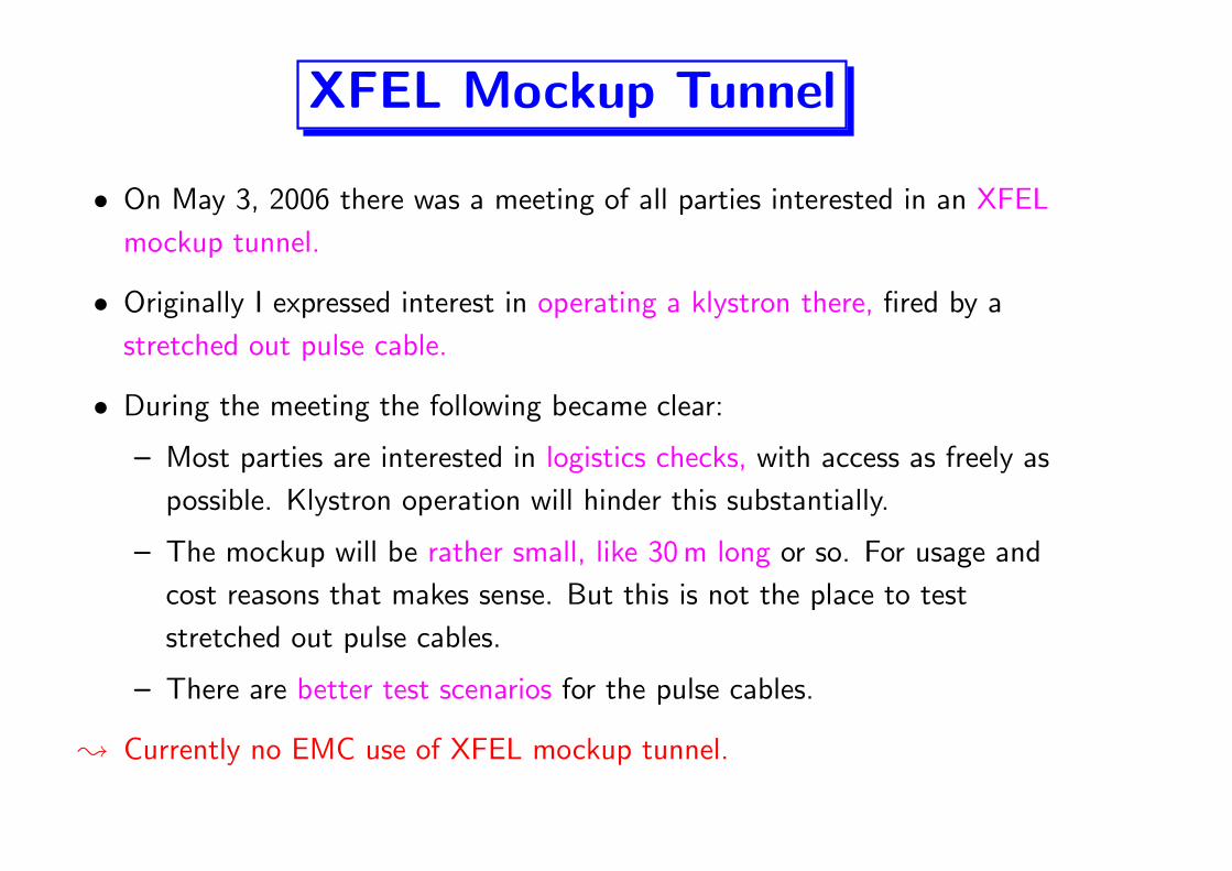
XFEL Mockup Tunnel
• On May 3, 2006 there was a meeting of all parties interested in an XFEL
mockup tunnel.
• Originally I expressed interest in operating a klystron there, fired by a
stretched out pulse cable.
• During the meeting the following became clear:
– Most parties are interested in logistics checks, with access as freely as
possible. Klystron operation will hinder this substantially.
– The mockup will be rather small, like 30 m long or so. For usage and
cost reasons that makes sense. But this is not the place to test
stretched out pulse cables.
– There are better test scenarios for the pulse cables.
� Currently no EMC use of XFEL mockup tunnel.
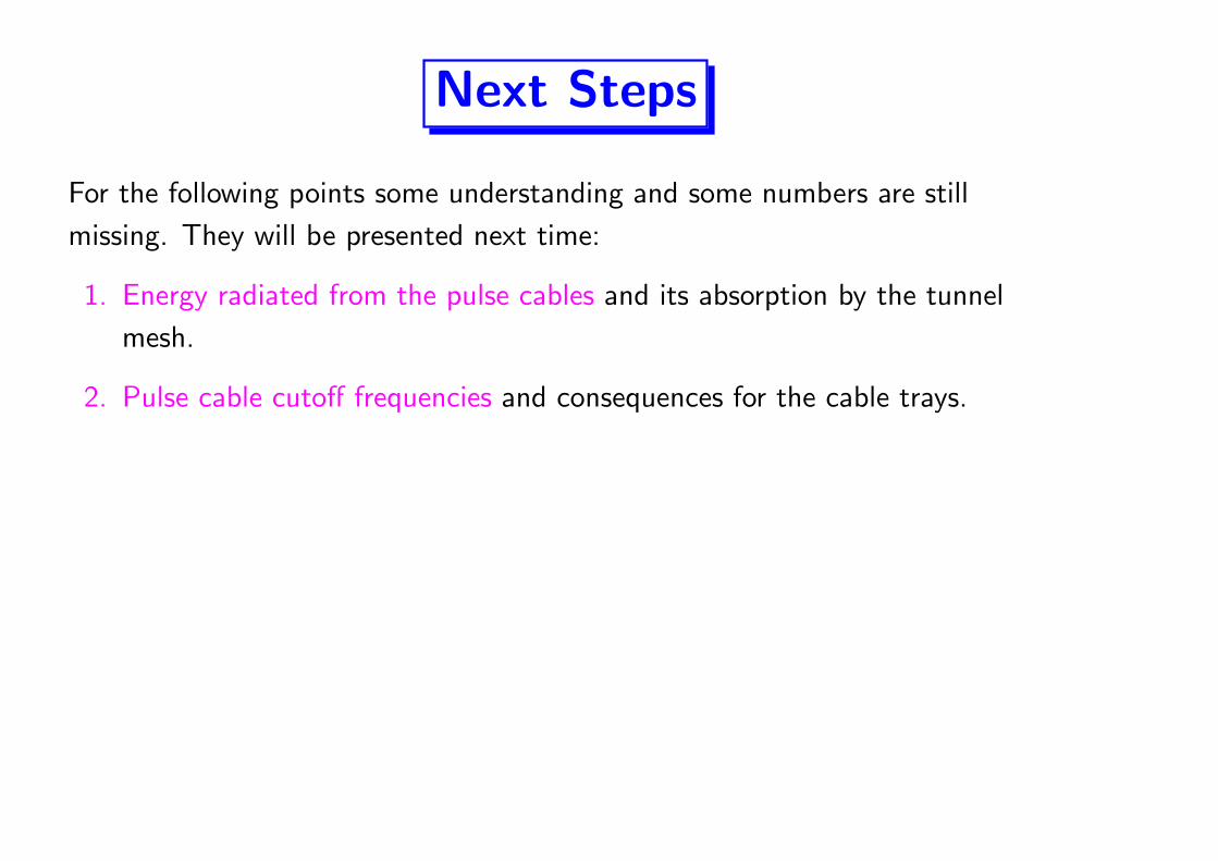
Next Steps
For the following points some understanding and some numbers are still
missing. They will be presented next time:
1. Energy radiated from the pulse cables and its absorption by the tunnel
mesh.
2. Pulse cable cutoff frequencies and consequences for the cable trays.
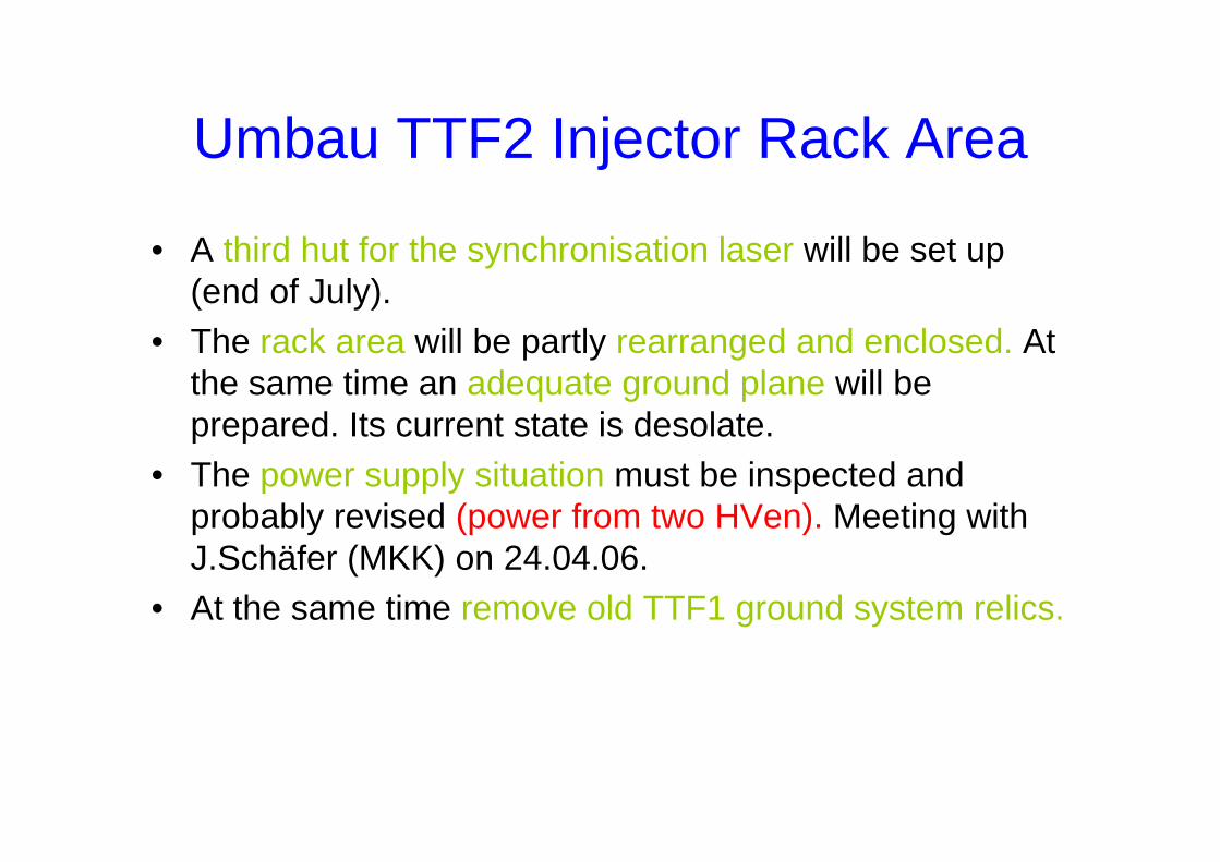
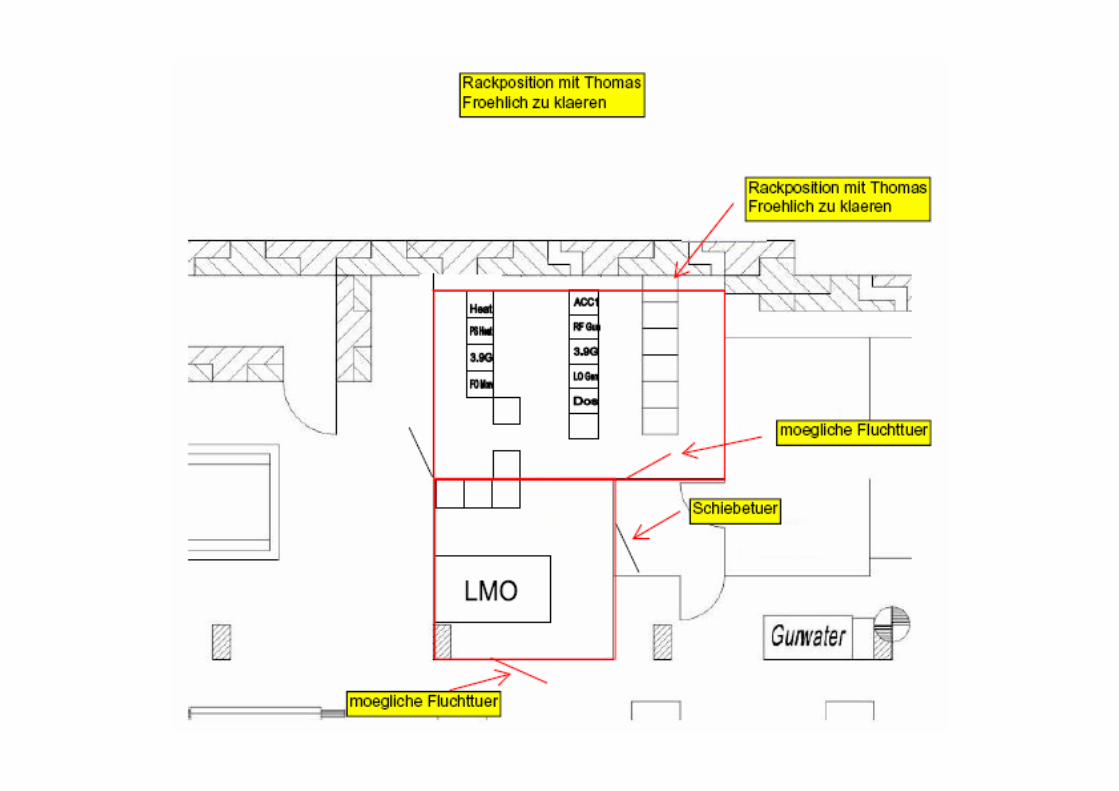
Umbau TTF2 Injector Rack Area
• A third hut for the synchronisation laser will be set up (end of July).
• The rack area will be partly rearranged and enclosed. At the same time an adequate ground plane will be prepared. Its current state is desolate.
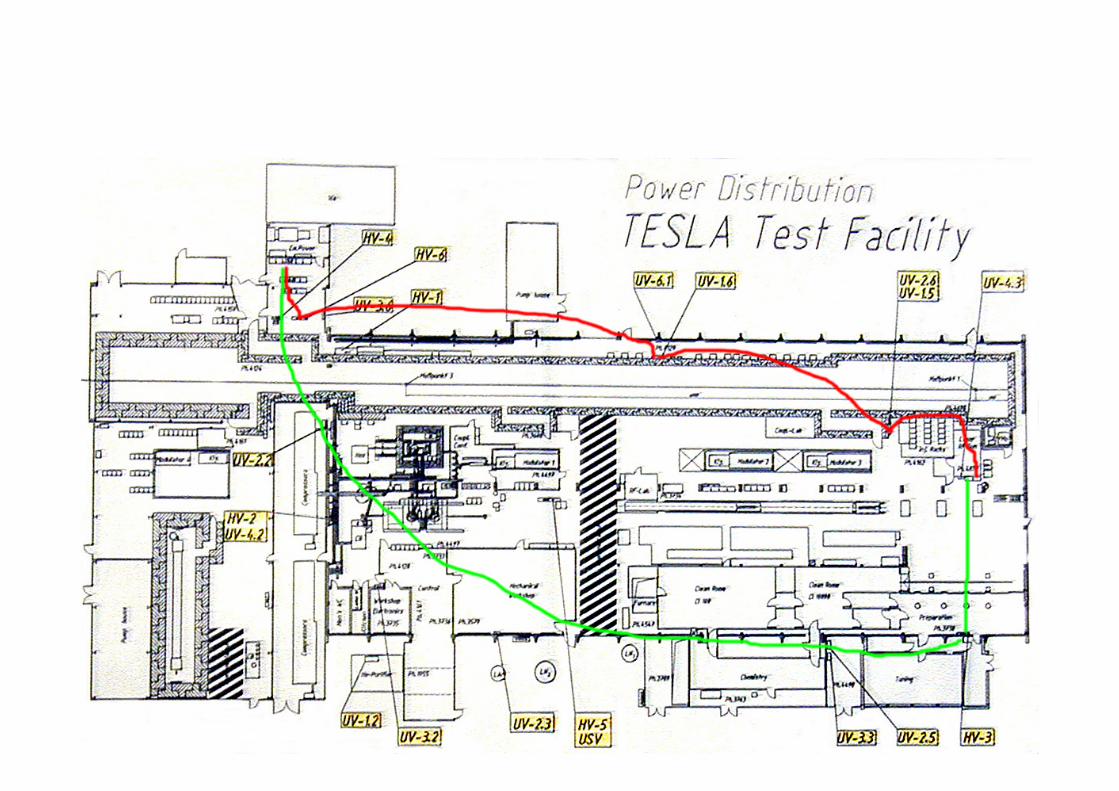
• The power supply situation must be inspected and probably revised (power from two HVen). Meeting with J.Schäfer (MKK) on 24.04.06.
• At the same time remove old TTF1 ground system relics.
EMI shielding for the new Injectorlaser
EMI shielding for the new Injectorlaser
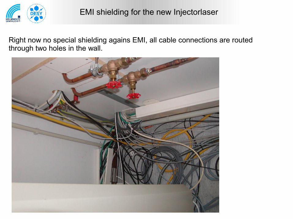
Right now no special shielding agains EMI, all cable connections are routed through two holes in the wall.
EMI shielding for the new Injectorlaser
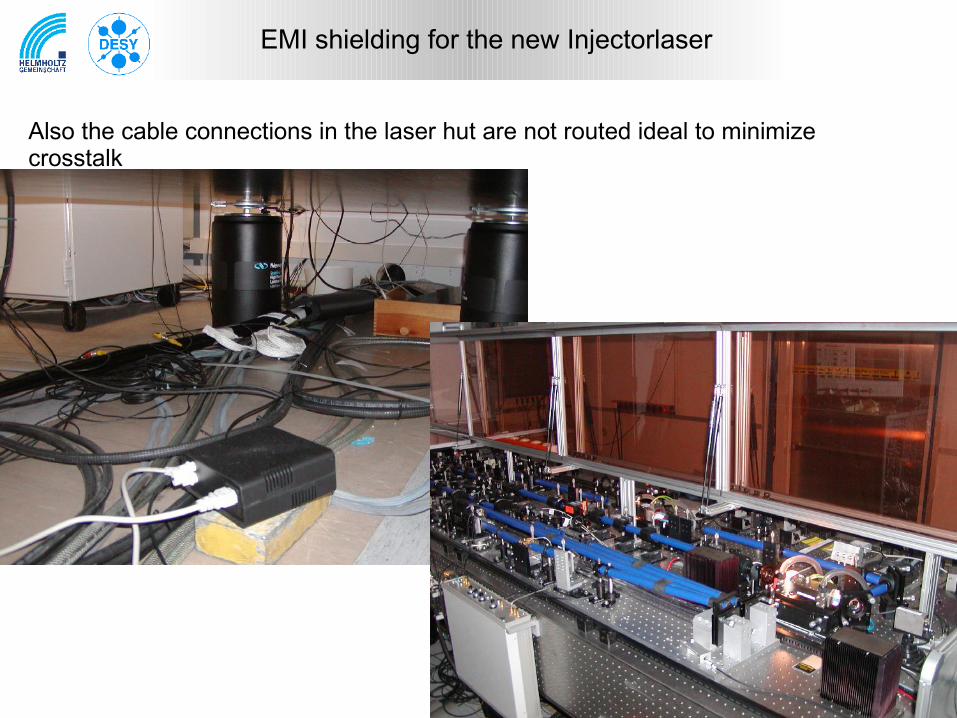
Also the cable connections in the laser hut are not routed ideal to minimize crosstalk
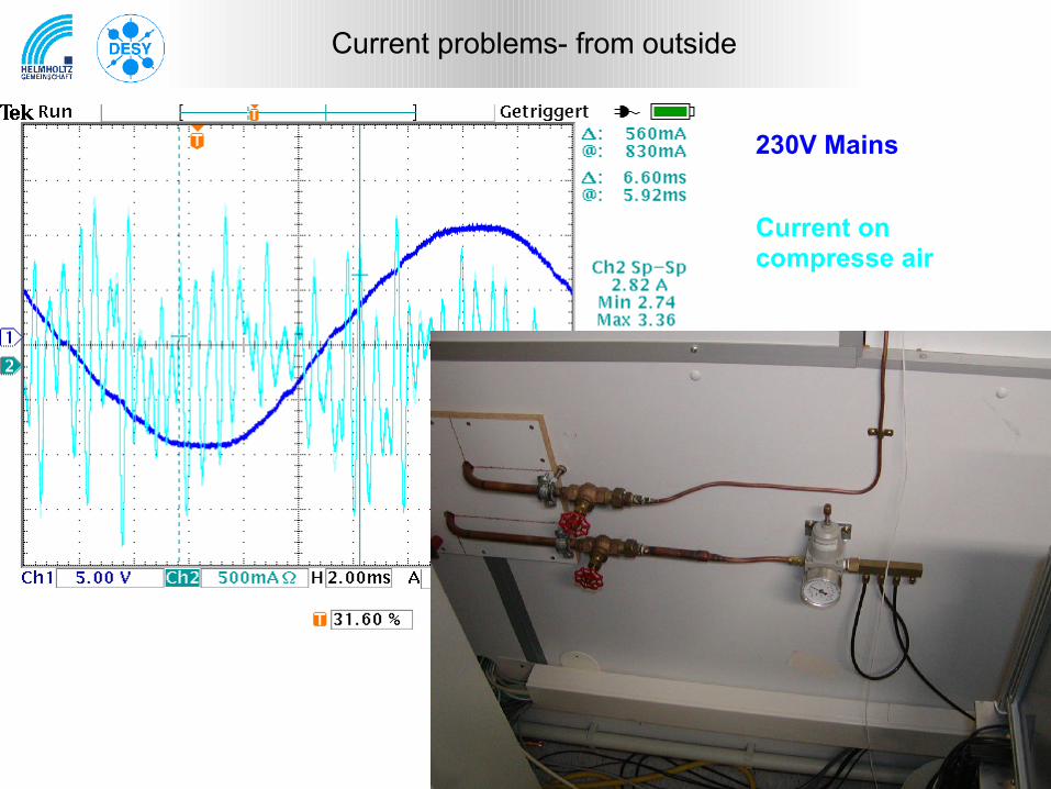
Current problems- from outside
230V Mains
Current on compresse air
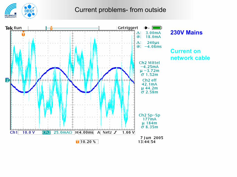
Current problems- from outside
230V Mains
Current onnetwork cable
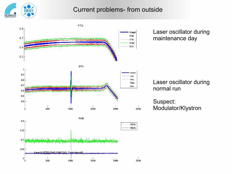
Laser oscillator during maintenance day
Laser oscillator during normal run
Suspect: Modulator/Klystron
Current problems- from outside
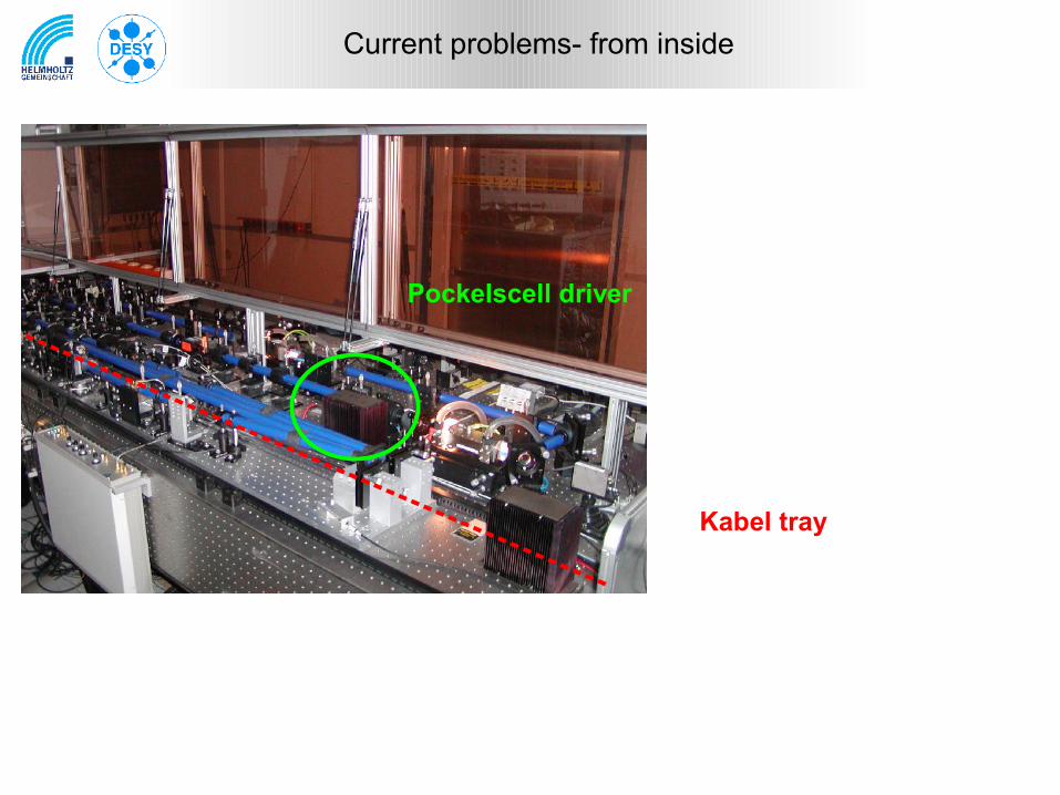
Current problems- from inside
Pockelscell driver
Kabel tray
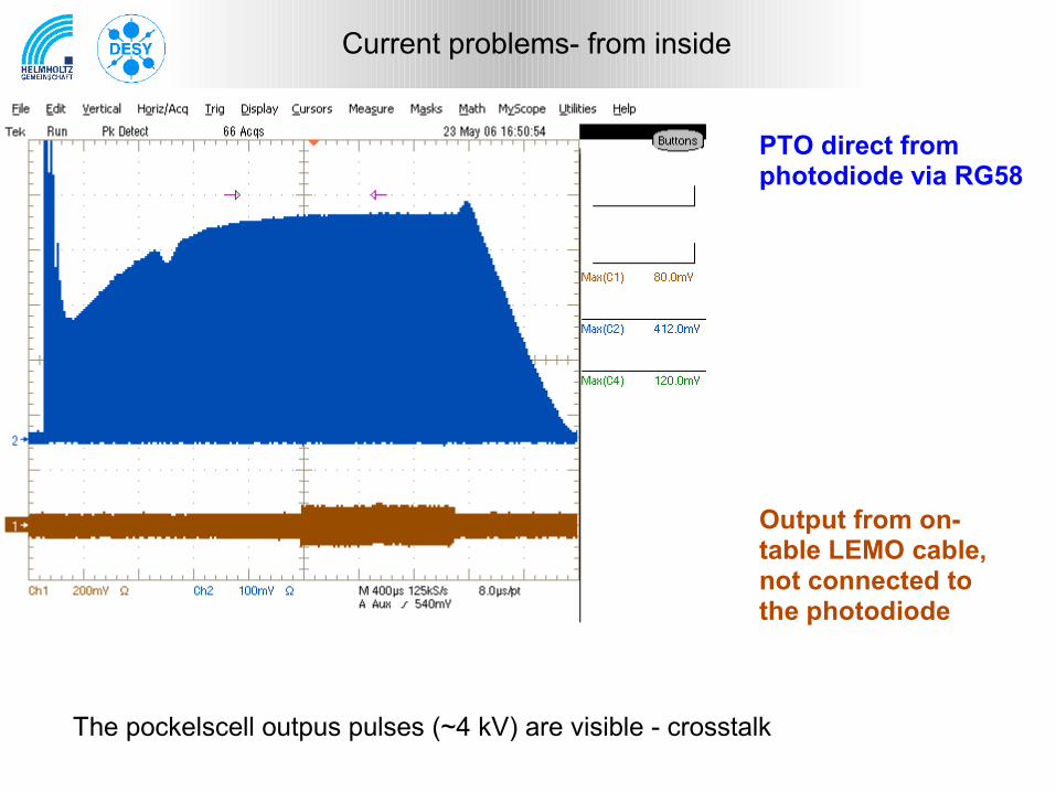
Current problems- from inside
PTO direct from photodiode via RG58
Output from on-table LEMO cable, not connected to the photodiode
The pockelscell outpus pulses (~4 kV) are visible - crosstalk
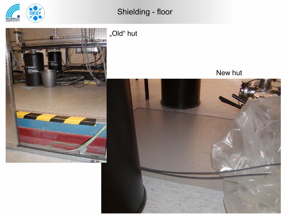
Shielding - floor
„Old“ hut
New hut
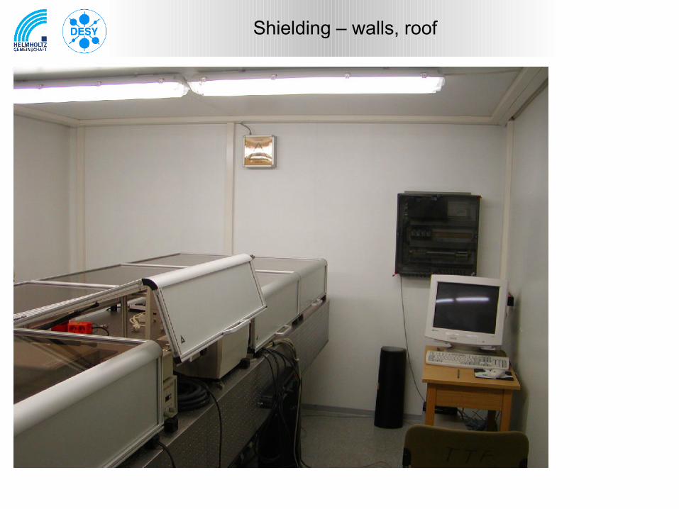
Shielding – walls, roof
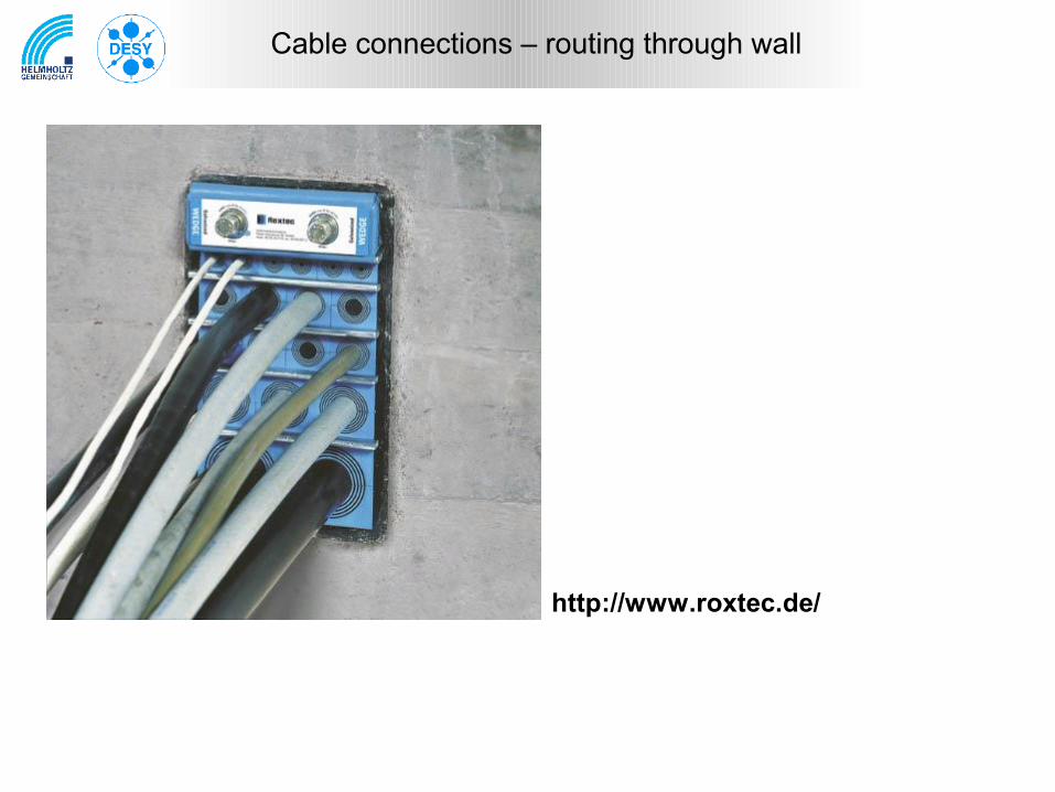
Cable connections – routing through wall
http://www.roxtec.de/
EthernetOld scheme: Standard twisped pair connection from the switch in the injector area to every deviceNew proposal: One fiber link from the old control room in the laser, a switch "satellite" in the laser hut. But the satellite offers 24 ports, overkill? contact person: Thorsten Witt, 4568. Is it possible to use this satellite for both huts? Alternative: Media converters to get fiber links from the Injctor area.
TimingOld:New proposal: Fiber optic connection into the hut, timing distribution in the laser hut.
RFOld scheme: RF-Cables from the master into the laser hut.New proposal: RF-Cables decoupled by a DC-block into the hut.
BIS (temperatures, (door-)interlocksOld scheme: Cables from the devices to the BIS-box in the hutNew proposal:
Cable connections
Motor-ControlOld scheme: CAN-Bus controller in the injector area, cables to each motor.New proposal: Beckhoff controller box in the laser-hut. Connected via ethernet. Problems with different hardware in old/new laser?
Distance measurementOld scheme: Pick-up connected by cable to the measurement transceiver in the injector area.New proposals: Not urgend needed, to be planned but not connected. Is there a possibility to put a filter in the cable connection?
MainsOld scheme: Standard connectionNew proposal: Use a line filter or transformer.
BICOld scheme: Ground free differential signal, opto coupled inputsNew proposal: -
Cable connections
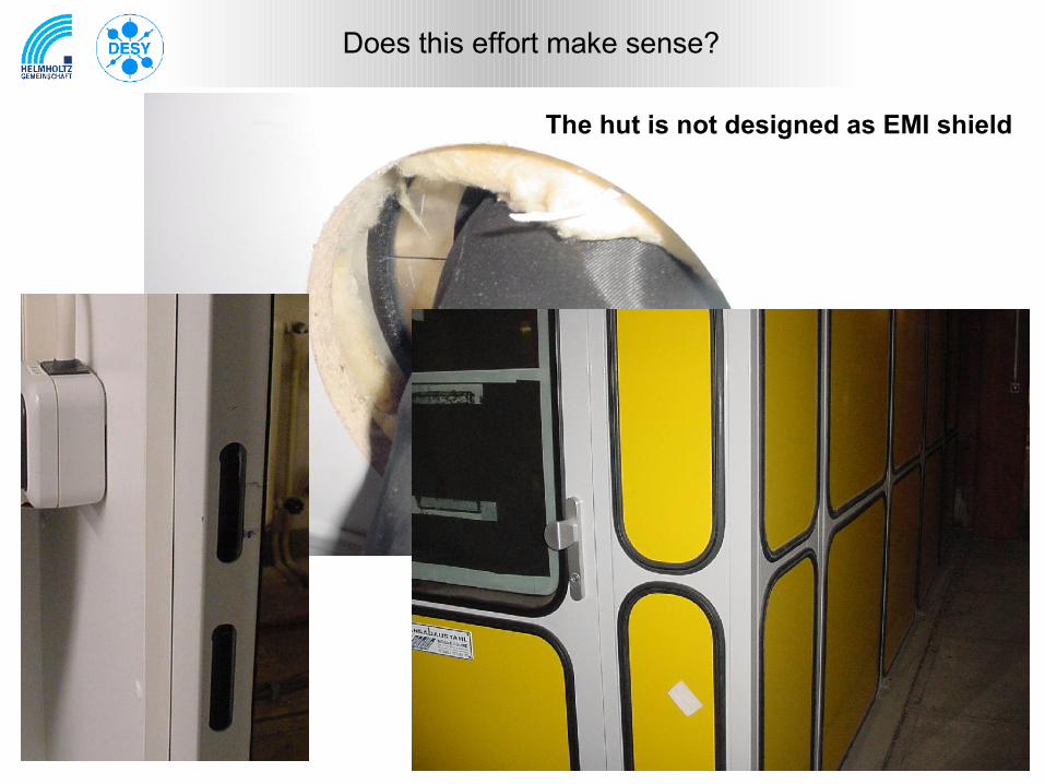
Does this effort make sense?
The hut is not designed as EMI shield
http://ttfinfo.desy.de/TTFelog/show.jsp?dir=/doc/SubSystems/Laser&pos=2006-05-17T09:38:07
Some considerations can be found in the logbook:
Company for cable connections (Hamburg):http://www.roxtec.de/
Some links
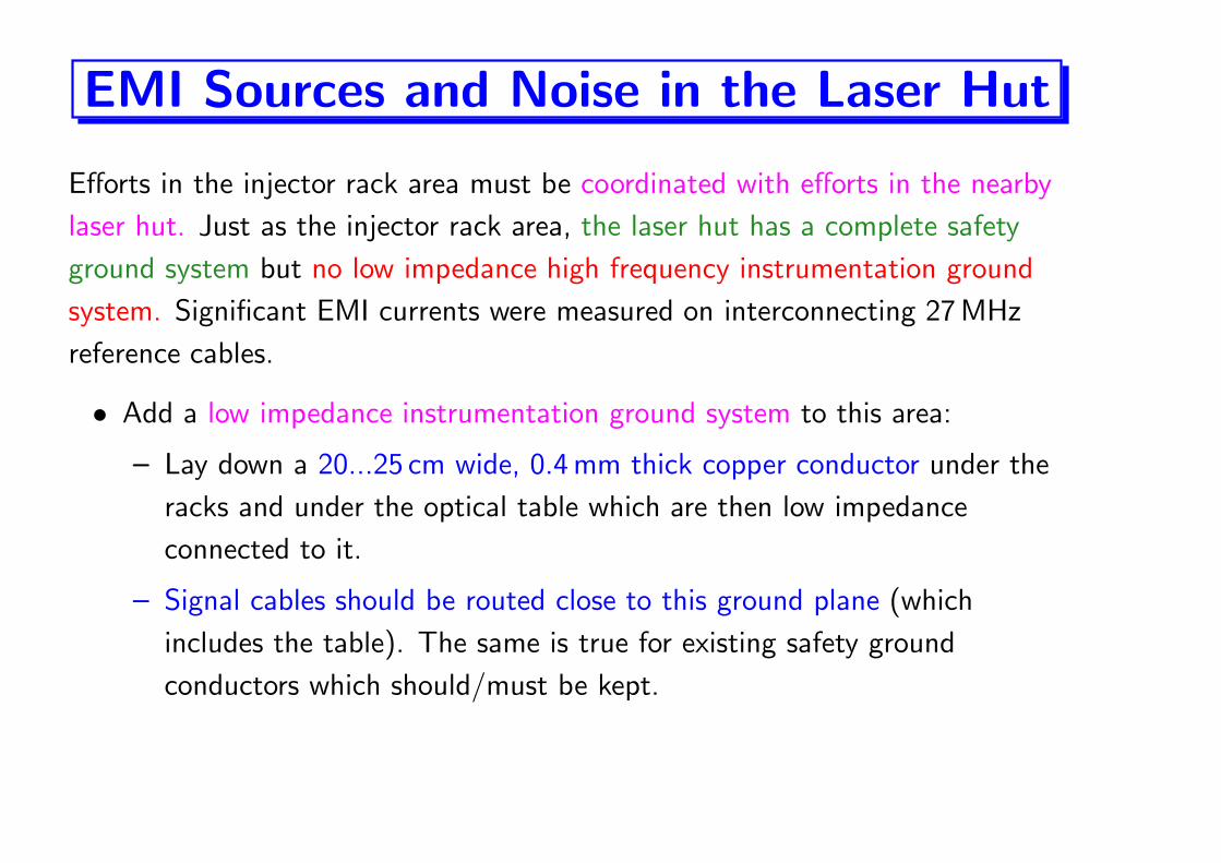
EMI Sources and Noise in the Laser Hut
Efforts in the injector rack area must be coordinated with efforts in the nearby
laser hut. Just as the injector rack area, the laser hut has a complete safety
ground system but no low impedance high frequency instrumentation ground
system. Significant EMI currents were measured on interconnecting 27 MHz
reference cables.
• Add a low impedance instrumentation ground system to this area:
– Lay down a 20...25 cm wide, 0.4 mm thick copper conductor under the
racks and under the optical table which are then low impedance
connected to it.
– Signal cables should be routed close to this ground plane (which
includes the table). The same is true for existing safety ground
conductors which should/must be kept.
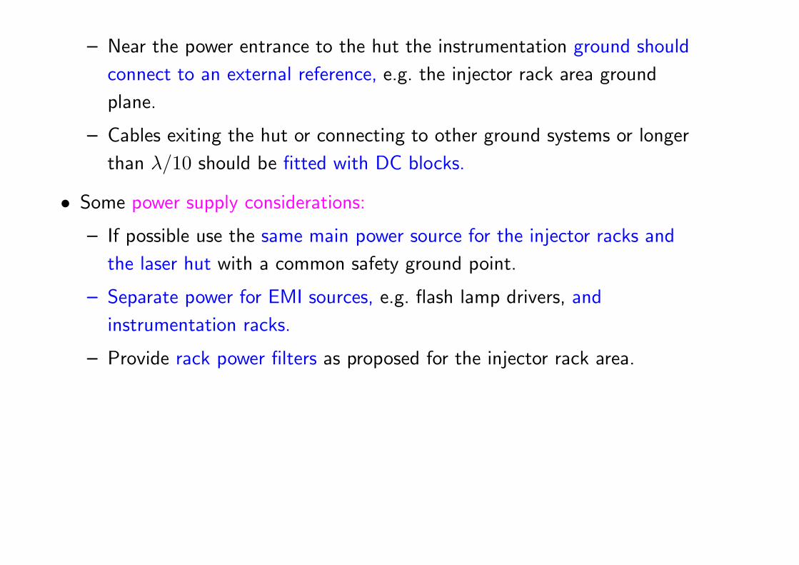
– Near the power entrance to the hut the instrumentation ground should
connect to an external reference, e.g. the injector rack area ground
plane.
– Cables exiting the hut or connecting to other ground systems or longer
than λ/10 should be fitted with DC blocks.
• Some power supply considerations:
– If possible use the same main power source for the injector racks and
the laser hut with a common safety ground point.
– Separate power for EMI sources, e.g. flash lamp drivers, and
instrumentation racks.
– Provide rack power filters as proposed for the injector rack area.
Recommended


![Project Nexus Steering Group [PNSG]](https://img.pdfslide.net/doc/110x75/61cac7d768108254a94172d7/project-nexus-steering-group-pnsg.jpg)