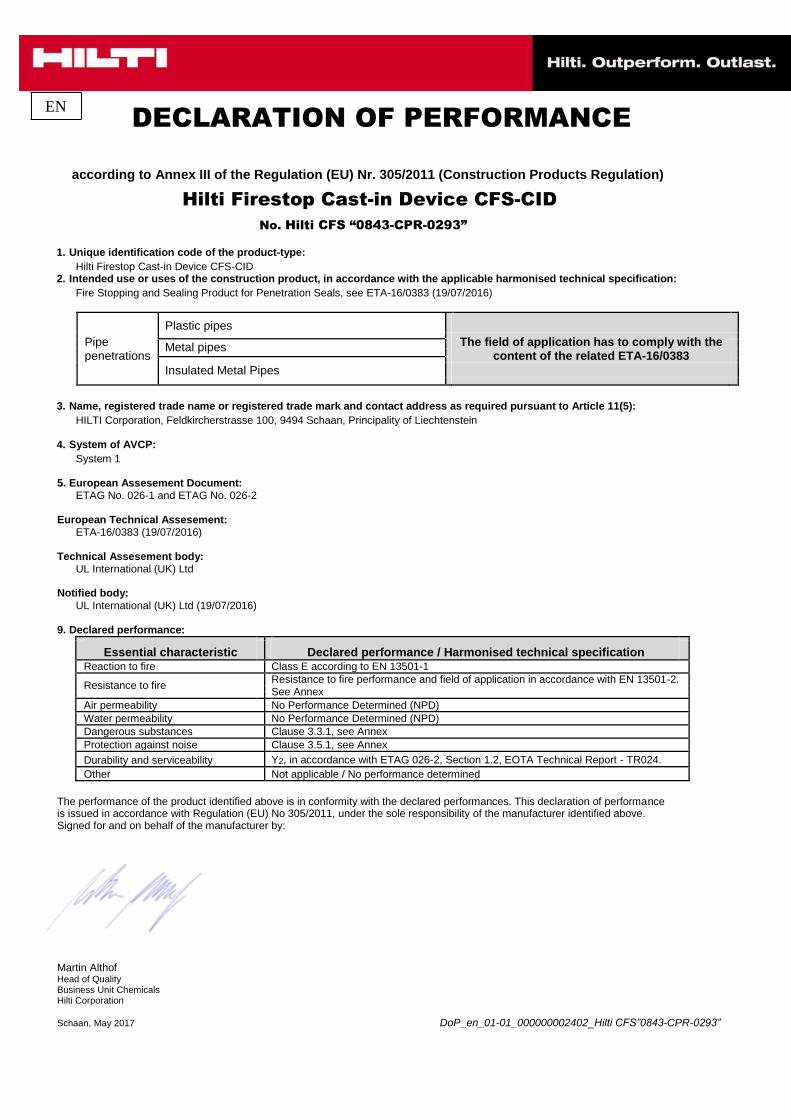
EN
DECLARATION OF PERFORMANCE
according to Annex III of the Regulation (EU) Nr. 305/2011 (Construction Products Regulation)
Hilti Firestop Cast-in Device CFS-CID
No. Hilti CFS “0843-CPR-0293” 1. Unique identification code of the product-type:
Hilti Firestop Cast-in Device CFS-CID 2. Intended use or uses of the construction product, in accordance with the applicable harmonised technical specification:
Fire Stopping and Sealing Product for Penetration Seals, see ETA-16/0383 (19/07/2016)
Plastic pipes
Pipe
The field of application has to comply with the
Metal pipes
penetrations
content of the related ETA-16/0383
Insulated Metal Pipes
3. Name, registered trade name or registered trade mark and contact address as required pursuant to Article 11(5):
HILTI Corporation, Feldkircherstrasse 100, 9494 Schaan, Principality of Liechtenstein 4. System of AVCP:
System 1 5. European Assesement Document:
ETAG No. 026-1 and ETAG No. 026-2 European Technical Assesement:
ETA-16/0383 (19/07/2016) Technical Assesement body:
UL International (UK) Ltd Notified body:
UL International (UK) Ltd (19/07/2016) 9. Declared performance:
Essential characteristic
Declared performance / Harmonised technical specification
Reaction to fire Class E according to EN 13501-1
Resistance to fire
Resistance to fire performance and field of application in accordance with EN 13501-2.
See Annex
Air permeability No Performance Determined (NPD)
Water permeability No Performance Determined (NPD)
Dangerous substances Clause 3.3.1, see Annex
Protection against noise Clause 3.5.1, see Annex
Durability and serviceability Y2, in accordance with ETAG 026-2, Section 1.2, EOTA Technical Report - TR024.
Other Not applicable / No performance determined
The performance of the product identified above is in conformity with the declared performances. This declaration of performance is issued in accordance with Regulation (EU) No 305/2011, under the sole responsibility of the manufacturer identified above. Signed for and on behalf of the manufacturer by:
Martin Althof Head of Quality Business Unit Chemicals Hilti Corporation Schaan, May 2017 DoP_en_01-01_000000002402_Hilti CFS”0843-CPR-0293”
1.1 Definition of the construction product
This European technical assessment refers to the Hilti Firestop Cast-in Device for use in Penetration Seals with the designation Hilti CFS-CID. Hilti Firestop Cast-in Device CFS-CID is a pipe closure device that is cast into rigid floors. Ancillary products referred to in this European technical assessment within the framework of evaluating resistance to fire (see Annexes 1 and 2) are not covered by this ETA and cannot be CE-marked on the basis of it.
Type of penetration seal system: Pipe closure device – cast in (see ETAG 026-2, clause 1.1, table 1-1). Hilti Firestop Cast-in Device CFS-CID consists of a plastic housing, an intumescent inlay and rubber seal for the purpose of smoke and draft stop, air or water tightness and airborne sound insulation.
Hilti Firestop Cast-in Device CFS-CID is supplied in several sizes – see table below.
For plastic pipes For insulated metal pipes
Pipe sealing size with nominal outside
nominal outside nominal pipe insulation
diameter range
diameter range range
(mm)
(mm) (mm)
CFS-CID 50 32 - 63 18 - 54 8 - 38
CFS-CID 75 50 - 75
CFS-CID 110 90 - 110 54 - 76 14 - 40,5
CFS-CID 160 125 - 160
For a description of the installation procedure see 3.1 and 3.2 2.2 Use category
Hilti Firestop Cast-in Device CFS-CID fulfils the requirements of use category Y2 in accordance with ETAG 026-2, Section 1.2.
Type Y2: Products intended for uses at internal conditions
3. Performance of the product and references to the methods used for its assessment 3.3 Hygiene, health and environment (BWR 3)
3.3.1 Release of dangerous substances
According to the manufacturer’s declaration, the product specification has been compared with the list of dangerous substances of the European Commission to verify that that it does not contain such substances above the acceptable limits.
A written declaration in this respect was submitted by the ETA-holder.
Note: In addition to the specific clauses relating to dangerous substances contained in this ETA, there may be other requirements applicable to the products falling within its scope (e.g. transposed European legislation and national laws, regulations and administrative provisions). In order to meet the provisions of the Construction Product Directive, these requirements need also to be complied with, when and where they apply.
3.4 Protection against noise (BWR 5) 3.5.1 Airborne sound insulation
Airborne sound insulation for a single penetration of a plastic pipe, fire stopped with Firestop Cast-in Device CFS-CID can only be achieved when the pipe closure device is casted in rigid floor.
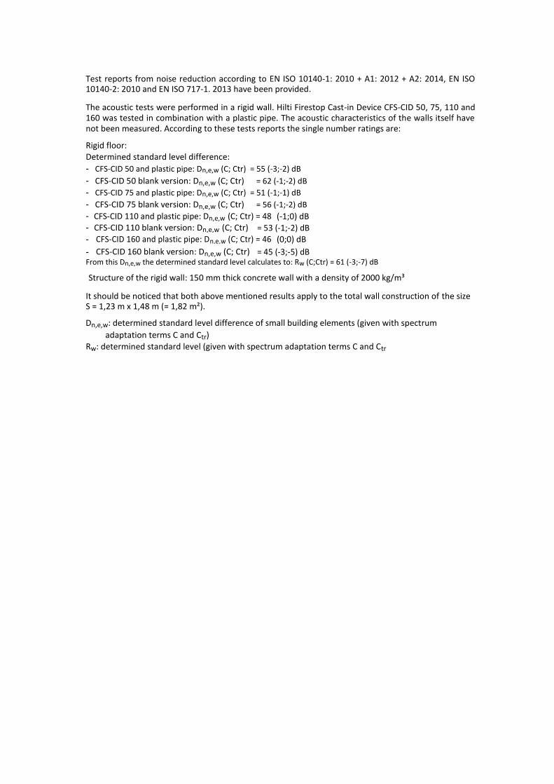
Test reports from noise reduction according to EN ISO 10140-1: 2010 + A1: 2012 + A2: 2014, EN ISO 10140-2: 2010 and EN ISO 717-1. 2013 have been provided.
The acoustic tests were performed in a rigid wall. Hilti Firestop Cast-in Device CFS-CID 50, 75, 110 and 160 was tested in combination with a plastic pipe. The acoustic characteristics of the walls itself have not been measured. According to these tests reports the single number ratings are:
Rigid floor: Determined standard level difference:
- CFS-CID 50 and plastic pipe: Dn,e,w (C; Ctr) = 55 (-3;-2) dB
- CFS-CID 50 blank version: Dn,e,w (C; Ctr) = 62 (-1;-2) dB
- CFS-CID 75 and plastic pipe: Dn,e,w (C; Ctr) = 51 (-1;-1) dB
- CFS-CID 75 blank version: Dn,e,w (C; Ctr) = 56 (-1;-2) dB
- CFS-CID 110 and plastic pipe: Dn,e,w (C; Ctr) = 48 (-1;0) dB
- CFS-CID 110 blank version: Dn,e,w (C; Ctr) = 53 (-1;-2) dB
- CFS-CID 160 and plastic pipe: Dn,e,w (C; Ctr) = 46 (0;0) dB
- CFS-CID 160 blank version: Dn,e,w (C; Ctr) = 45 (-3;-5) dB From this Dn,e,w the determined standard level calculates to: Rw (C;Ctr) = 61 (-3;-7) dB
Structure of the rigid wall: 150 mm thick concrete wall with a density of 2000 kg/m³
It should be noticed that both above mentioned results apply to the total wall construction of the size S = 1,23 m x 1,48 m (= 1,82 m²).
Dn,e,w: determined standard level difference of small building elements (given with spectrum
adaptation terms C and Ctr) Rw: determined standard level (given with spectrum adaptation terms C and Ctr
ANNEX 1
DESCRIPTION OF THE PRODUCT AND ANCILLARY PRODUCT(S)
Hilti Firestop Cast-in Device CFS-CID
The Cast-in device consists of a plastic housing, an inlay with different number of intumescent layers, and a rubber gasket. In case of greater floor thicknesses (>150mm) the Cast-in device length can be increased through an extension tube. Manifold adapter to create a spacing of 280 x 280 x 75 mm.
A detailed specification of the product is contained in document “Identification / Product Specification relating to the European technical assessment ETA – 16/0383 Hilti Firestop Cast-in Device CFS-CID” which is a non-public part of this ETA.
The Control Plan defined in document "Control Plan is relating to the European technical assessment ETA – 16/0383 Hilti Firestop Cast-in Device CFS-CID” which is a non-public part of this ETA.
Technical product literature: Installation instruction Hilti Firestop Cast-in Device CFS-CID (according to Annex 3).
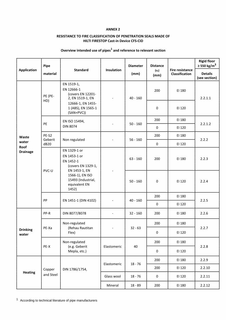
ANNEX 2
RESISTANCE TO FIRE CLASSIFICATION OF PENETRATION SEALS MADE OF HILTI FIRESTOP Cast-in Device CFS-CID
Overview intended use of pipes1 and reference to relevant section
Distance
Rigid floor
Pipe Diameter Fire resistance
≥ 550 kg/m3
Application material
Standard Insulation
(s1)
(mm) Details
(mm) Classification
(see section)
EN 1519-1,
EN 12666-1 200 EI 180
(covers EN 12201-
PE (PE-
2, EN 1519-1, EN - 40 - 160 2.2.1.1
HD)
12666-1, EN 1455-
1 (ABS), EN 1565-1 0 EI 120
(SAN+PVC))
EN ISO 15494, 200 EI 180
PE - 50 - 160
2.2.1.2
DIN 8074 0 EI 120
Waste PE-S2 200 EI 180
Geberit Non regulated - 56 - 160 2.2.2
water 0 EI 120
dB20
Roof
EN 1329-1 or
Drainage
EN 1453-1 or 63 - 160 200 EI 180 2.2.3
EN 1452-1
(covers EN 1329-1,
PVC-U EN 1453-1, EN -
1566-1), EN ISO
15493 (Industrial, 50 - 160 0 EI 120 2.2.4
equivalent EN
1452)
200 EI 180
PP EN 1451-1 (DIN 4102) - 40 - 160 2.2.5
0 EI 120
PP-R DIN 8077/8078 - 32 - 160 200 EI 180 2.2.6
Non-regulated 200 EI 180
Drinking PE-Xa (Rehau Rautitan - 32 - 63
2.2.7
0 EI 120
Flex)
water
Non-regulated 200 EI 180
PE-X (e.g. Geberit Elastomeric 40
2.2.8
0 EI 120
Mepla, etc.)
200 EI 180 2.2.9
Elastomeric 18 - 76
Copper DIN 1786/1754, 200 EI 120 2.2.10
Heating
and Steel
Glass wool 18 - 76 0 EI 120 2.2.11
Mineral 18 - 89 200 EI 180 2.2.12
1 According to technical literature of pipe manufacturers
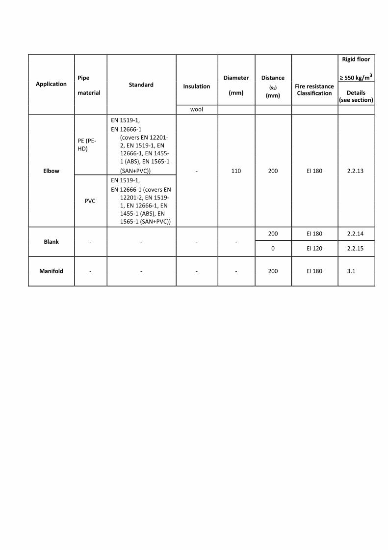
Application
Standard
Distance
Rigid floor
Pipe Diameter
Fire resistance
≥ 550 kg/m3
material Insulation
(mm) (s1)
Details
(mm) Classification
(see section)
wool
EN 1519-1,
EN 12666-1
PE (PE-
(covers EN 12201-
2, EN 1519-1, EN
HD)
12666-1, EN 1455-
1 (ABS), EN 1565-1
Elbow (SAN+PVC)) - 110 200 EI 180 2.2.13
EN 1519-1,
EN 12666-1 (covers EN
PVC
12201-2, EN 1519-
1, EN 12666-1, EN
1455-1 (ABS), EN
1565-1 (SAN+PVC))
200 EI 180 2.2.14
Blank - - - -
0 EI 120 2.2.15
Manifold - - - - 200 EI 180 3.1
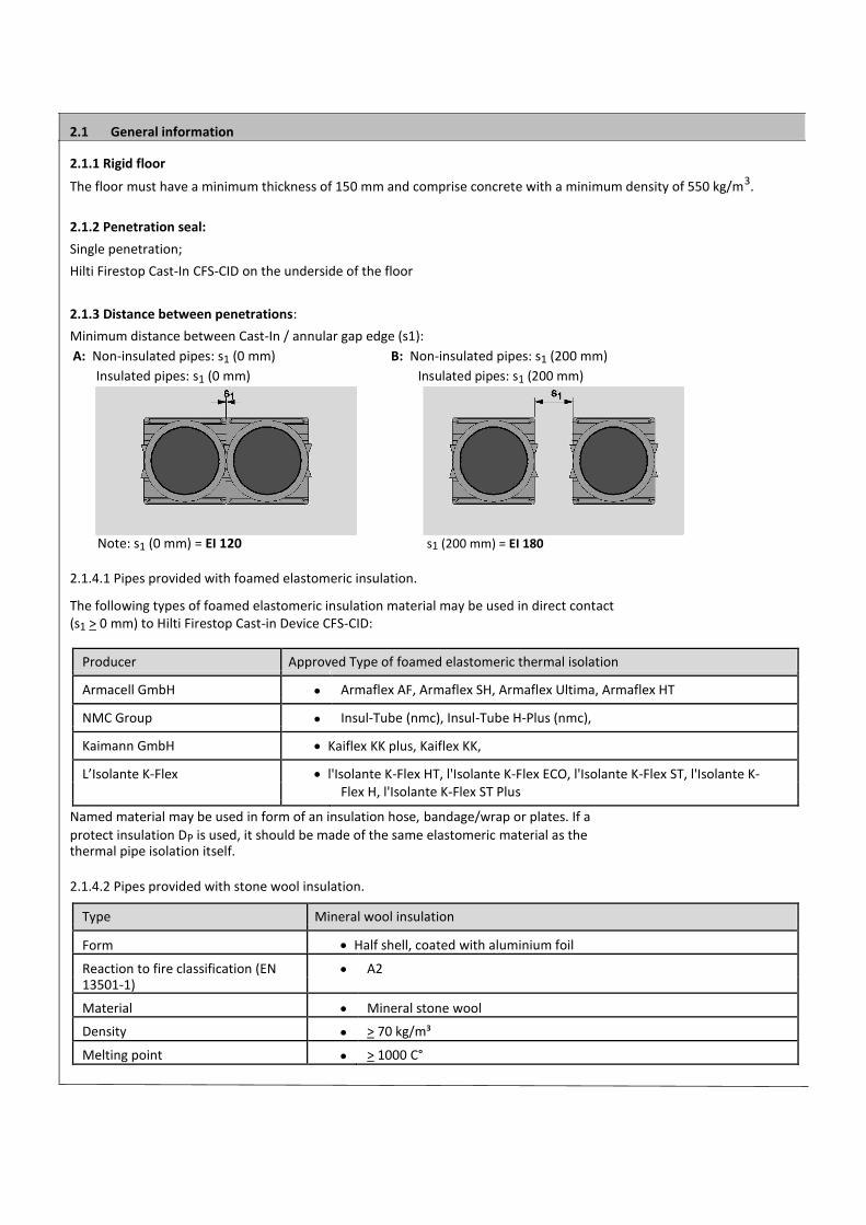
2.1 General information
2.1.1 Rigid floor
The floor must have a minimum thickness of 150 mm and comprise concrete with a minimum density of 550 kg/m3.
2.1.2 Penetration seal: Single penetration; Hilti Firestop Cast-In CFS-CID on the underside of the floor
2.1.3 Distance between penetrations: Minimum distance between Cast-In / annular gap edge (s1):
A: Non-insulated pipes: s1 (0 mm) B: Non-insulated pipes: s1 (200 mm)
Insulated pipes: s1 (0 mm) Insulated pipes: s1 (200 mm)
Note: s1 (0 mm) = EI 120 s1 (200 mm) = EI 180
2.1.4.1 Pipes provided with foamed elastomeric insulation. The following types of foamed elastomeric insulation material may be used in direct contact (s1 > 0 mm) to Hilti Firestop Cast-in Device CFS-CID:
Producer Approved Type of foamed elastomeric thermal isolation
Armacell GmbH Armaflex AF, Armaflex SH, Armaflex Ultima, Armaflex HT
NMC Group Insul-Tube (nmc), Insul-Tube H-Plus (nmc),
Kaimann GmbH Kaiflex KK plus, Kaiflex KK,
L’Isolante K-Flex l'Isolante K-Flex HT, l'Isolante K-Flex ECO, l'Isolante K-Flex ST, l'Isolante K- Flex H, l'Isolante K-Flex ST Plus
Named material may be used in form of an insulation hose, bandage/wrap or plates. If a
protect insulation DP is used, it should be made of the same elastomeric material as the thermal pipe isolation itself.
2.1.4.2 Pipes provided with stone wool insulation.
Type Mineral wool insulation
Form Half shell, coated with aluminium foil
Reaction to fire classification (EN A2 13501-1)
Material Mineral stone wool
Density > 70 kg/m³
Melting point > 1000 C°
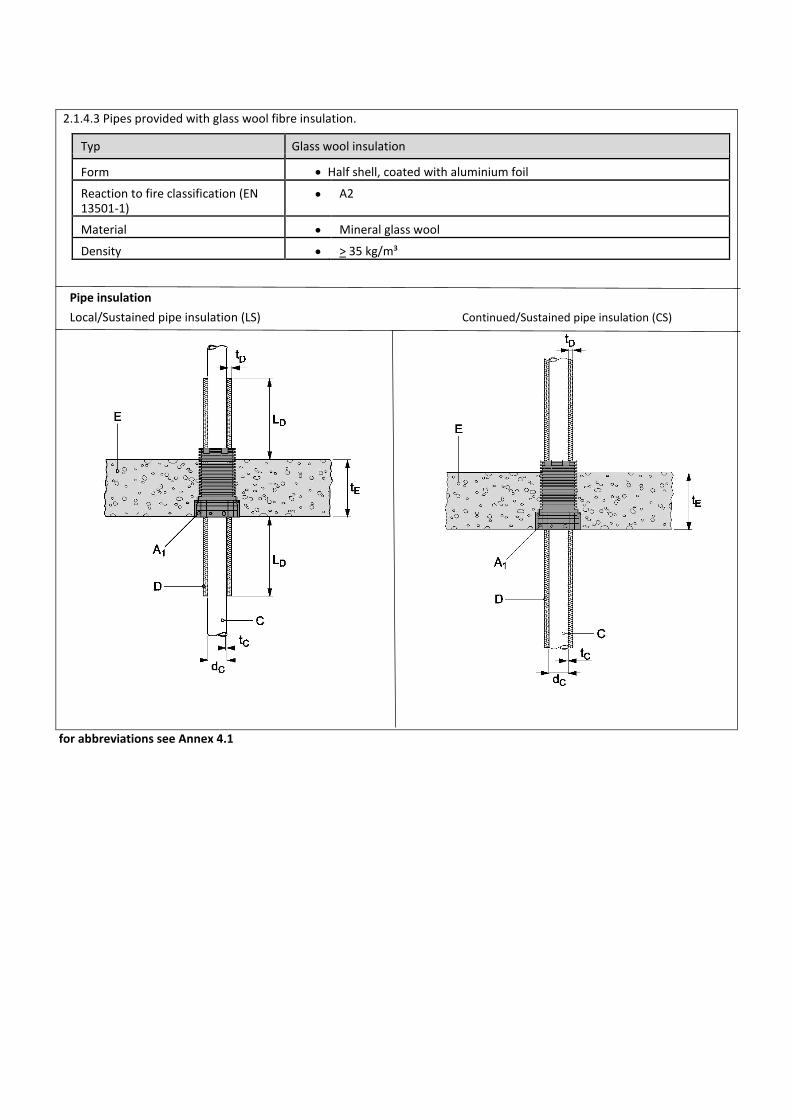
2.1.4.3 Pipes provided with glass wool fibre insulation.
Typ Glass wool insulation
Form Half shell, coated with aluminium foil
Reaction to fire classification (EN A2 13501-1)
Material Mineral glass wool
Density > 35 kg/m³
Pipe insulation
Local/Sustained pipe insulation (LS) Continued/Sustained pipe insulation (CS)
for abbreviations see Annex 4.1
2.2 Penetrating services approved with CFS-CID
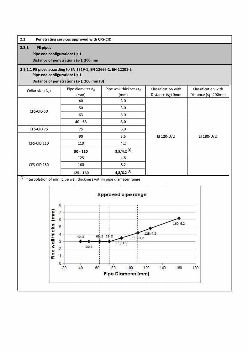
2.2.1 PE pipes
Pipe end configuration: U/U
Distance of penetrations (s1): 200 mm
2.2.1.1 PE pipes according to EN 1519-1, EN 12666-1, EN 12201-2
Pipe end configuration: U/U
Distance of penetrations (s1): 200 mm (B)
Collar size (A1) Pipe diameter dc Pipe wall thickness tc Classification with Classification with
(mm) (mm) Distance (s1) 0mm Distance (s1) 200mm
40 3,0
CFS-CID 50
50 3,0
63 3,0
40 - 63 3,0
CFS-CID 75 75 3,0
EI 120-U/U EI 180-U/U 90 3,5
CFS-CID 110 110 4,2
90 - 110 3,5/4,2 (1)
125 4,8
CFS-CID 160 160 6,2
125 - 160 4,8/6,2 (1)
(1) interpolation of min. pipe wall thickness within pipe diameter range
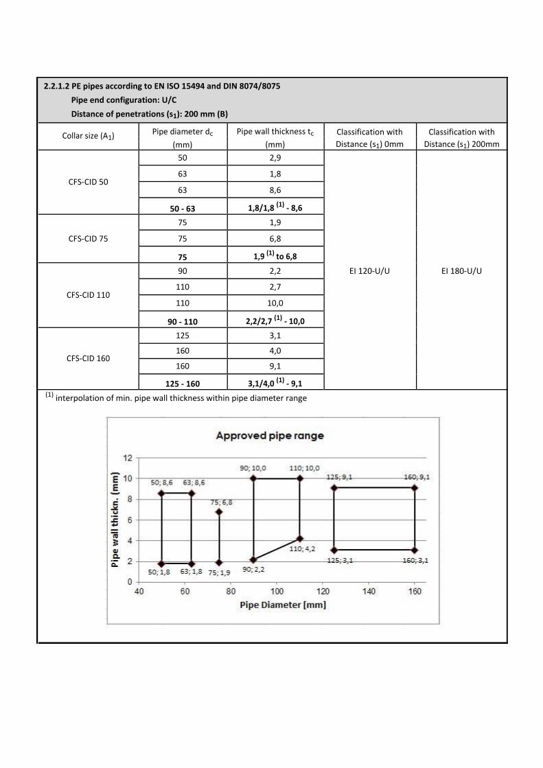
2.2.1.2 PE pipes according to EN ISO 15494 and DIN 8074/8075
Pipe end configuration: U/C
Distance of penetrations (s1): 200 mm (B)
Collar size (A1) Pipe diameter dc Pipe wall thickness tc Classification with Classification with
(mm) (mm) Distance (s1) 0mm Distance (s1) 200mm
50 2,9
CFS-CID 50 63 1,8
63 8,6
50 - 63 1,8/1,8 (1) - 8,6
75 1,9
CFS-CID 75 75 6,8
75 1,9 (1) to 6,8
90 2,2 EI 120-U/U EI 180-U/U
CFS-CID 110 110 2,7
110 10,0
90 - 110 2,2/2,7 (1) - 10,0
125 3,1
CFS-CID 160 160 4,0
160 9,1
125 - 160 3,1/4,0 (1) - 9,1 (1) interpolation of min. pipe wall thickness within pipe diameter range
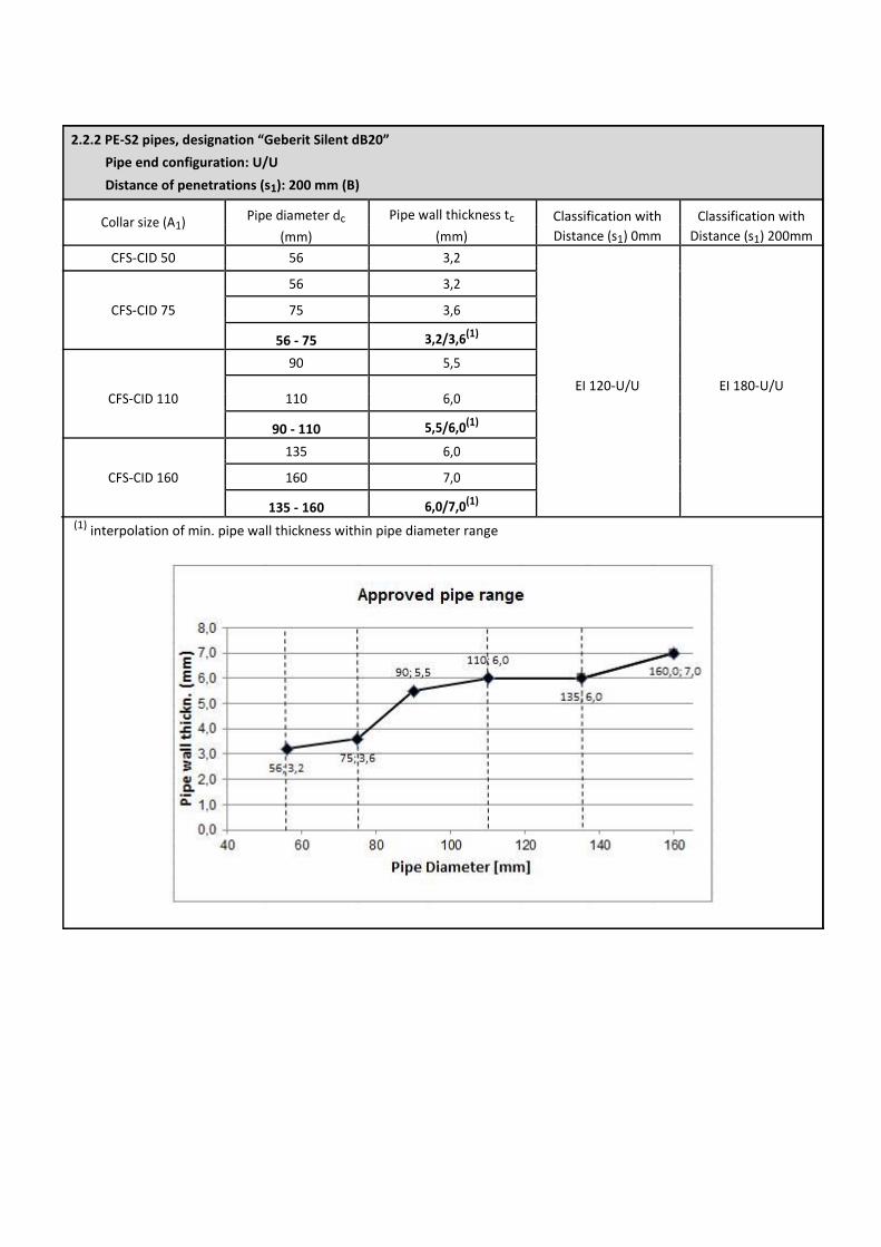
2.2.2 PE-S2 pipes, designation “Geberit Silent dB20”
Pipe end configuration: U/U
Distance of penetrations (s1): 200 mm (B)
Collar size (A1) Pipe diameter dc Pipe wall thickness tc Classification with Classification with
(mm) (mm) Distance (s1) 0mm Distance (s1) 200mm
CFS-CID 50 56 3,2
56 3,2
CFS-CID 75 75 3,6
56 - 75 3,2/3,6(1)
90 5,5
EI 120-U/U EI 180-U/U
CFS-CID 110 110 6,0
90 - 110 5,5/6,0(1)
135 6,0
CFS-CID 160 160 7,0
135 - 160 6,0/7,0(1)
(1) interpolation of min. pipe wall thickness within pipe diameter range
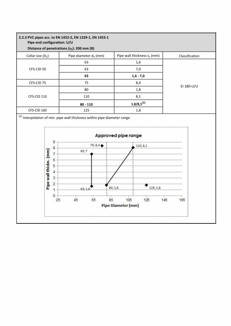
2.2.3 PVC pipes acc. to EN 1452-2, EN 1329-1, EN 1453-1
Pipe end configuration: U/U
Distance of penetrations (s1): 200 mm (B)
Collar size (A1) Pipe diameter dc (mm) Pipe wall thickness tc (mm) Classification
63 1,6
CFS-CID 50 63 7,0
63 1,6 - 7,0
CFS-CID 75 75 8,4 EI 180-U/U
80 1,8
CFS-CID 110 110 8,1
80 - 110 1,8/8,1(1)
CFS-CID 160 125 1,8
(1) interpolation of min. pipe wall thickness within pipe diameter range
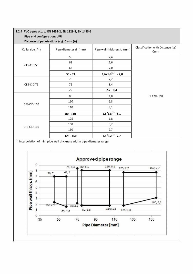
2.2.4 PVC pipes acc. to EN 1452-2, EN 1329-1, EN 1453-1
Pipe end configuration: U/U
Distance of penetrations (s1): 0 mm (A)
Collar size (A1) Pipe diameter dc (mm) Pipe wall thickness tc (mm) Classification with Distance (s1)
0mm
50 2,4
CFS-CID 50 63 1,6
63 7,0
50 - 63 1,6/1,6(1) - 7,0
75 2,2
CFS-CID 75 75 8,4
75 2,2 - 8,4
80 1,8 EI 120-U/U
CFS-CID 110 110 1,8
110 8,1
80 - 110 1,8/1,8(1) - 8,1
125 1,8
CFS-CID 160 160 3,2
160 7,7
125 - 160 1,8/3,2(1) - 7,7
(1) interpolation of min. pipe wall thickness within pipe diameter range
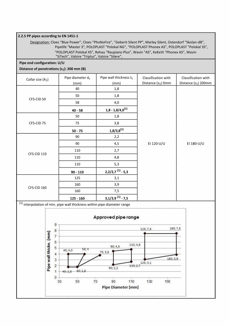
2.2.5 PP pipes according to EN 1451-1
Designation: Cloes “Blue Power”, Cloes “PhoNoFire”, “Geberit Silent PP”, Marley Silent, Ostendorf “Skolan-dB”, Pipelife "Master 3", POLOPLAST "Polokal NG", “POLOPLAST Phonex AS”, POLOPLAST "Polokal 3S",
“POLOPLAST Polokal XS”, Rehau "Raupiano Plus”, Wavin "AS”, KeKelit “Phonex AS”, Wavin "SiTech”, Valsire “Triplus”, Valsire “Silere”,
Pipe end configuration: U/U
Distance of penetrations (s1): 200 mm (B)
Collar size (A1) Pipe diameter dc Pipe wall thickness tc Classification with Classification with
(mm) (mm) Distance (s1) 0mm Distance (s1) 200mm
40 1,8
CFS-CID 50 50 1,8
58 4,0
40 - 58 1,8 - 1,8/4,0(1)
50 1,8
CFS-CID 75 75 3,8
50 - 75 1,8/3,8(1)
90 2,2
EI 120-U/U EI 180-U/U 90 4,5
CFS-CID 110 110 2,7
110 4,8
110 5,3
90 - 110 2,2/2,7 (1) - 5,3
125 3,1
CFS-CID 160 160 3,9
160 7,5
125 - 160 3,1/3,9 (1) - 7,5 (1) interpolation of min. pipe wall thickness within pipe diameter range
2.2.6 PP-R pipes designation “Aquatherm”
Pipe end configuration: U/C
Distance of penetrations (s1): 200 mm (B)
Collar size (A1) Pipe diameter dc (mm) Pipe wall thickness tc (mm) Classification with Distance (s1)
200mm
32 2,9
CFS-CID 50 50 4,6
63 5,8
32 - 63 2,9/5,8 (1)
75 6,8 EI 180-U/C
CFS-CID 75 75 10,7
75 6,8 - 10,7
CFS-CID 110 90 8,2
CFS-CID 160 160 14,6
(1) interpolation of min. pipe wall thickness within pipe diameter range
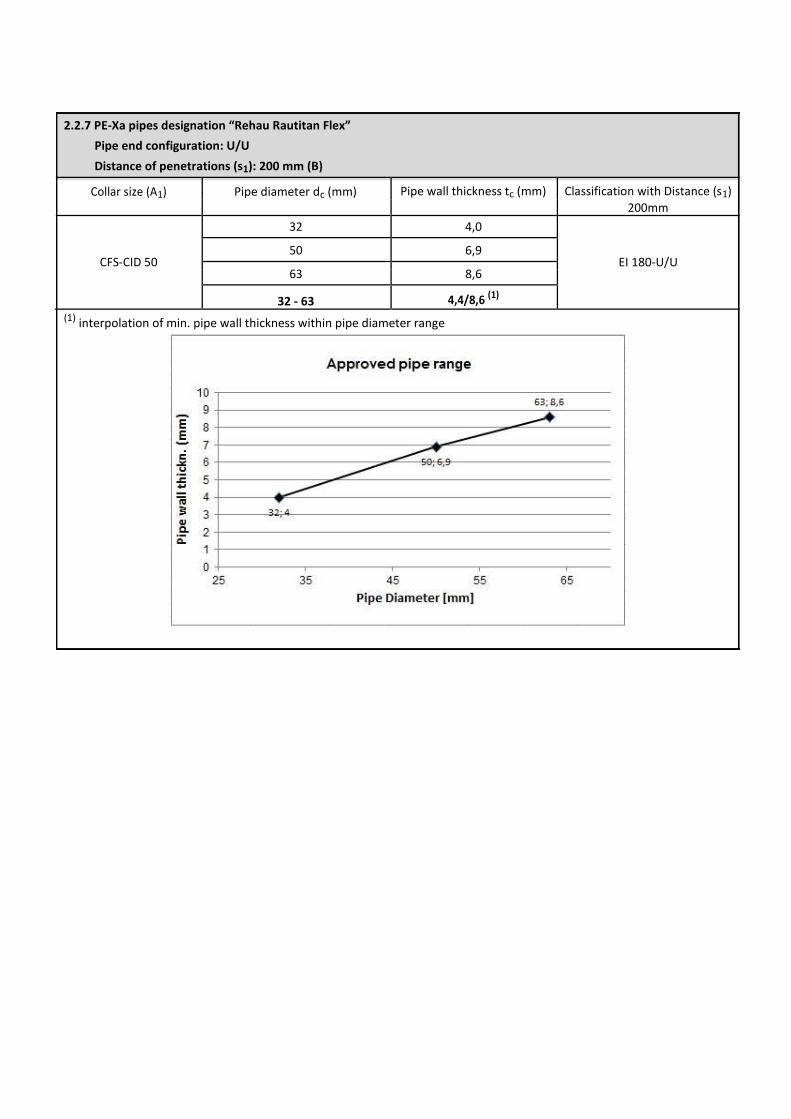
2.2.7 PE-Xa pipes designation “Rehau Rautitan Flex”
Pipe end configuration: U/U
Distance of penetrations (s1): 200 mm (B)
Collar size (A1) Pipe diameter dc (mm) Pipe wall thickness tc (mm) Classification with Distance (s1)
200mm
32 4,0
CFS-CID 50 50 6,9
EI 180-U/U
63 8,6
32 - 63 4,4/8,6 (1)
(1) interpolation of min. pipe wall thickness within pipe diameter range
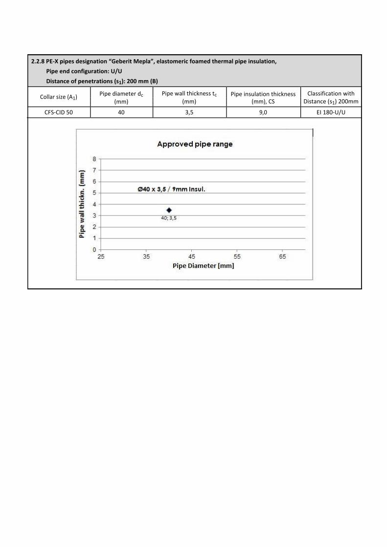
2.2.8 PE-X pipes designation “Geberit Mepla”, elastomeric foamed thermal pipe insulation,
Pipe end configuration: U/U
Distance of penetrations (s1): 200 mm (B)
Collar size (A1) Pipe diameter dc Pipe wall thickness tc Pipe insulation thickness Classification with
Distance (s1) 200mm
(mm) (mm) (mm), CS
CFS-CID 50 40 3,5 9,0 EI 180-U/U
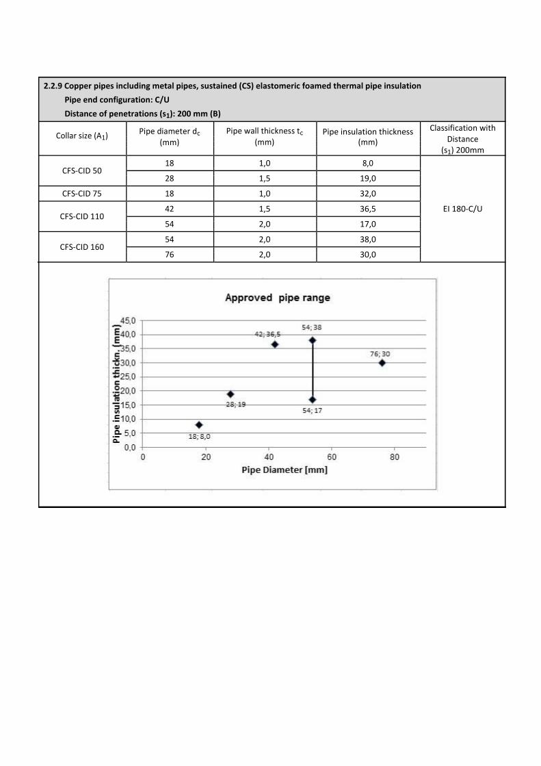
2.2.9 Copper pipes including metal pipes, sustained (CS) elastomeric foamed thermal pipe insulation
Pipe end configuration: C/U
Distance of penetrations (s1): 200 mm (B)
Collar size (A1) Pipe diameter dc Pipe wall thickness tc Pipe insulation thickness Classification with Distance
(s1) 200mm
(mm) (mm) (mm)
CFS-CID 50 18 1,0 8,0
28 1,5 19,0
CFS-CID 75 18 1,0 32,0
CFS-CID 110 42 1,5 36,5 EI 180-C/U
54 2,0 17,0
CFS-CID 160 54 2,0 38,0
76 2,0 30,0
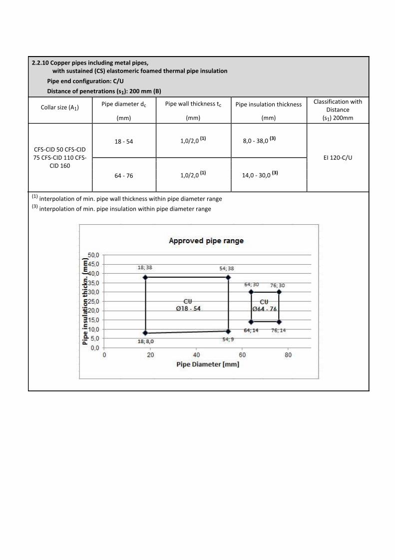
2.2.10 Copper pipes including metal pipes, with sustained (CS) elastomeric foamed thermal pipe insulation
Pipe end configuration: C/U
Distance of penetrations (s1): 200 mm (B)
Collar size (A1) Pipe diameter dc Pipe wall thickness tc Pipe insulation thickness Classification with
Distance
(s1) 200mm
(mm) (mm) (mm)
18 - 54 1,0/2,0 (1) 8,0 - 38,0 (3)
CFS-CID 50 CFS-CID
75 CFS-CID 110 CFS- EI 120-C/U
CID 160
64 - 76 1,0/2,0 (1) 14,0 - 30,0 (3)
(1) interpolation of min. pipe wall thickness within pipe diameter range (3) interpolation of min. pipe insulation within pipe diameter range
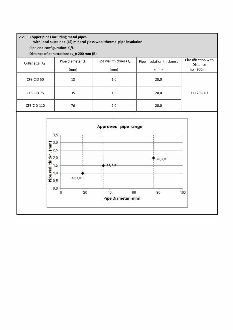
2.2.11 Copper pipes including metal pipes, with local sustained (LS) mineral glass wool thermal pipe insulation
Pipe end configuration: C/U
Distance of penetrations (s1): 200 mm (B)
Collar size (A1) Pipe diameter dc Pipe wall thickness tc Pipe insulation thickness Classification with
Distance
(s1) 200mm
(mm) (mm) (mm)
CFS-CID 50 18 1,0 20,0
EI 120-C/U
CFS-CID 75 35 1,5 20,0
CFS-CID 110 76 2,0 20,0
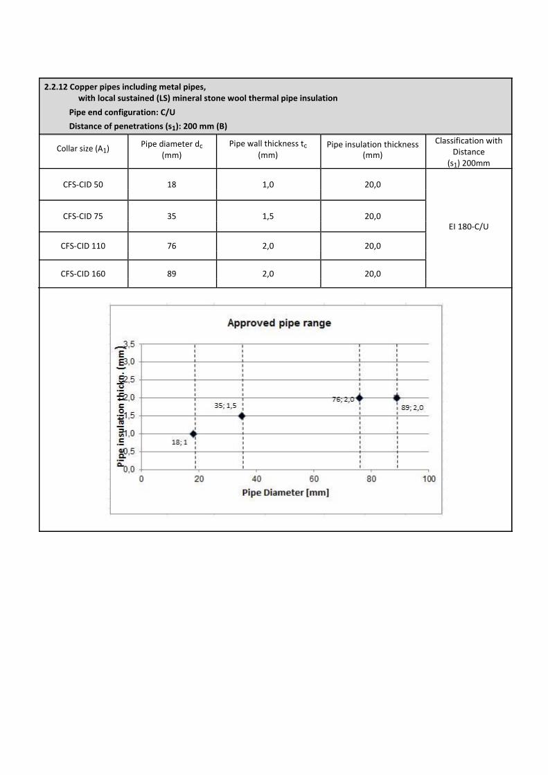
2.2.12 Copper pipes including metal pipes, with local sustained (LS) mineral stone wool thermal pipe insulation
Pipe end configuration: C/U
Distance of penetrations (s1): 200 mm (B)
Collar size (A1) Pipe diameter dc Pipe wall thickness tc Pipe insulation thickness Classification with
Distance
(s1) 200mm
(mm) (mm) (mm)
CFS-CID 50 18 1,0 20,0
CFS-CID 75 35 1,5 20,0
EI 180-C/U
CFS-CID 110 76 2,0 20,0
CFS-CID 160 89 2,0 20,0
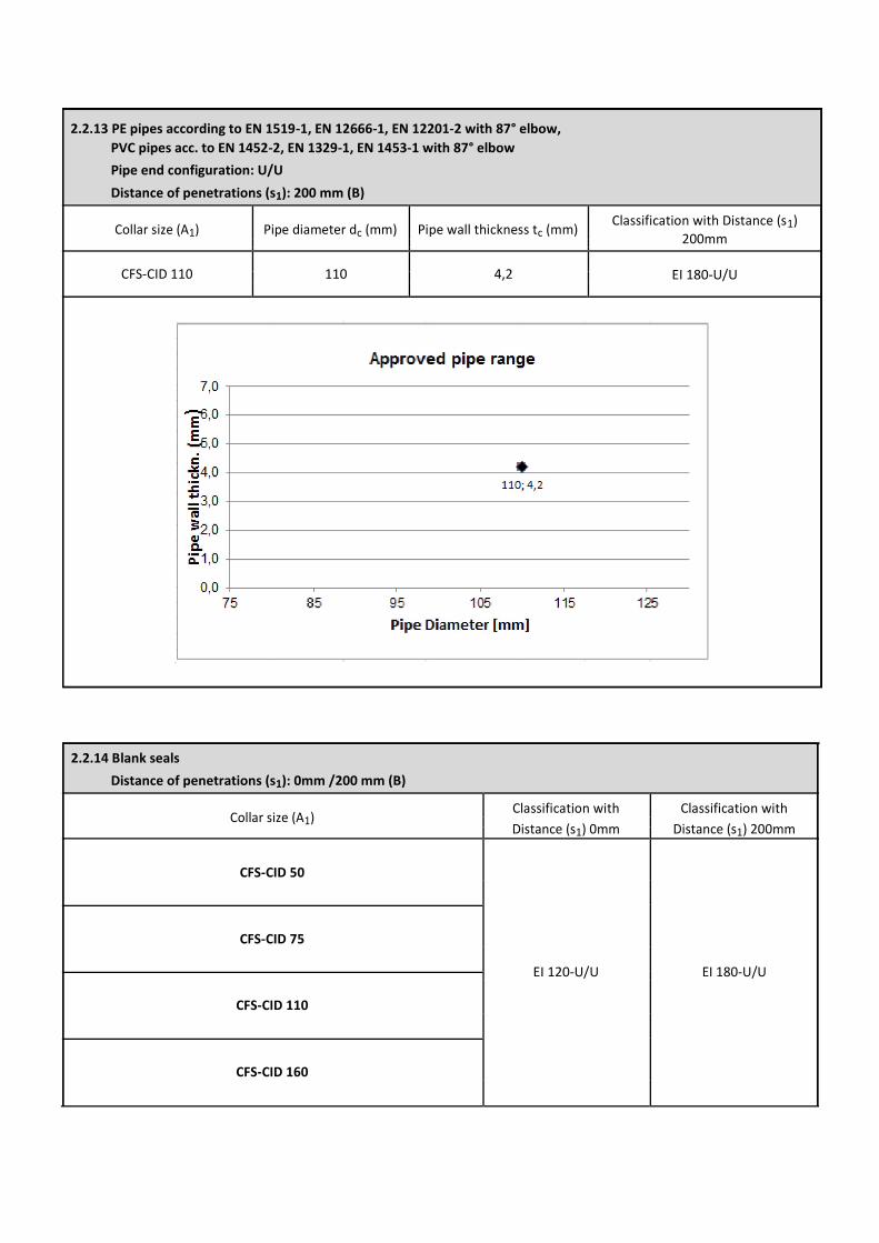
2.2.13 PE pipes according to EN 1519-1, EN 12666-1, EN 12201-2 with 87° elbow,
PVC pipes acc. to EN 1452-2, EN 1329-1, EN 1453-1 with 87° elbow Pipe end configuration: U/U Distance of penetrations (s1): 200 mm (B)
Collar size (A1) Pipe diameter dc (mm) Pipe wall thickness tc (mm) Classification with Distance (s1)
200mm
CFS-CID 110 110 4,2 EI 180-U/U
2.2.14 Blank seals
Distance of penetrations (s1): 0mm /200 mm (B)
Collar size (A1) Classification with Classification with
Distance (s1) 0mm Distance (s1) 200mm
CFS-CID 50
CFS-CID 75
EI 120-U/U EI 180-U/U
CFS-CID 110
CFS-CID 160
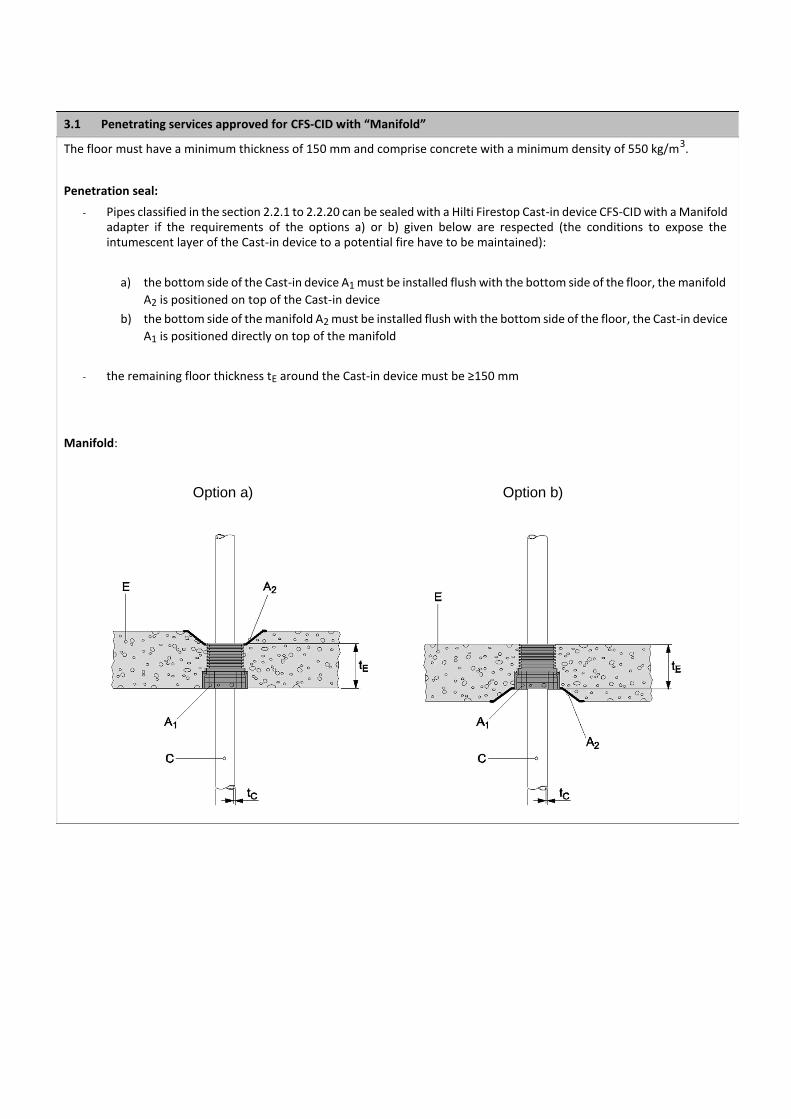
3.1 Penetrating services approved for CFS-CID with “Manifold”
The floor must have a minimum thickness of 150 mm and comprise concrete with a minimum density of 550 kg/m3.
Penetration seal:
- Pipes classified in the section 2.2.1 to 2.2.20 can be sealed with a Hilti Firestop Cast-in device CFS-CID with a Manifold adapter if the requirements of the options a) or b) given below are respected (the conditions to expose the intumescent layer of the Cast-in device to a potential fire have to be maintained):
a) the bottom side of the Cast-in device A1 must be installed flush with the bottom side of the floor, the manifold
A2 is positioned on top of the Cast-in device b) the bottom side of the manifold A2 must be installed flush with the bottom side of the floor, the Cast-in device
A1 is positioned directly on top of the manifold
- the remaining floor thickness tE around the Cast-in device must be ≥150 mm
Manifold:
Option a) Option b)
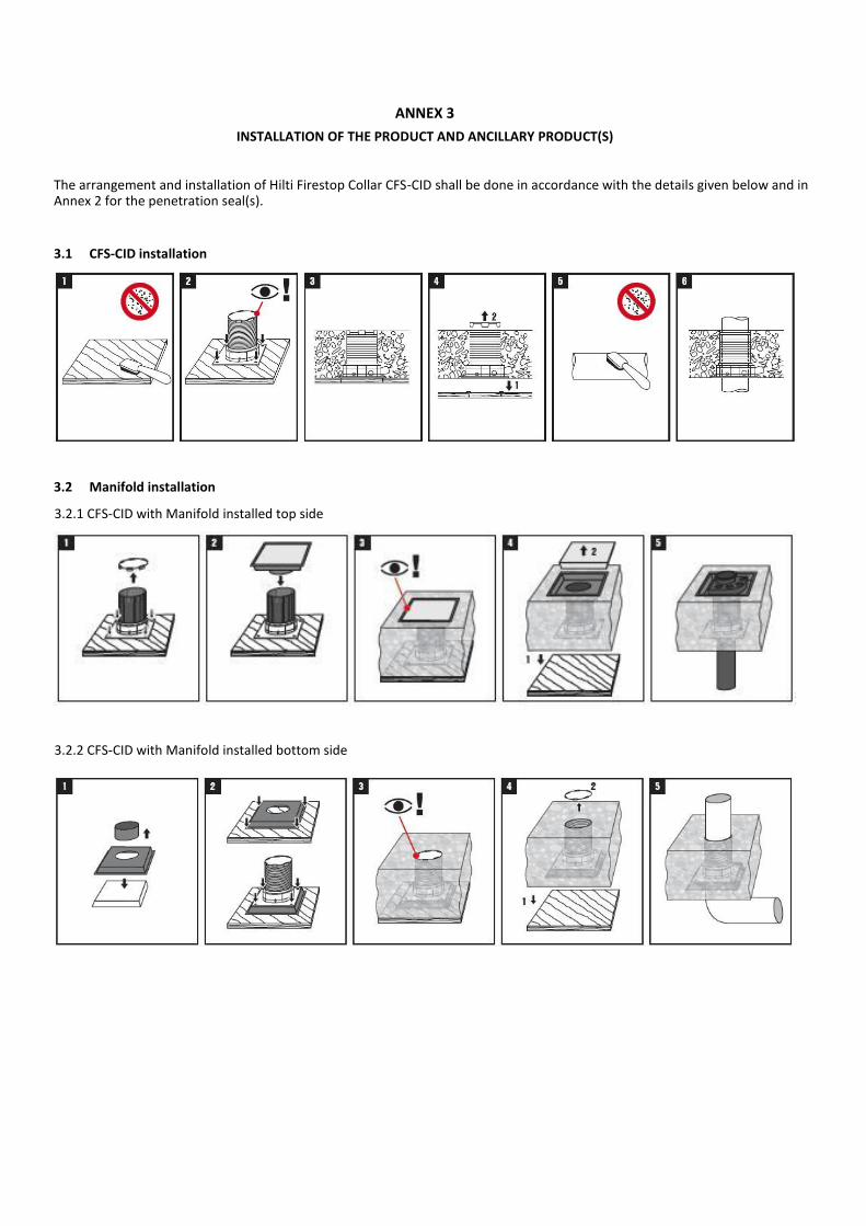
ANNEX 3
INSTALLATION OF THE PRODUCT AND ANCILLARY PRODUCT(S) The arrangement and installation of Hilti Firestop Collar CFS-CID shall be done in accordance with the details given below and in Annex 2 for the penetration seal(s).
3.1 CFS-CID installation
3.2 Manifold installation 3.2.1 CFS-CID with Manifold installed top side
3.2.2 CFS-CID with Manifold installed bottom side
ANNEX 4
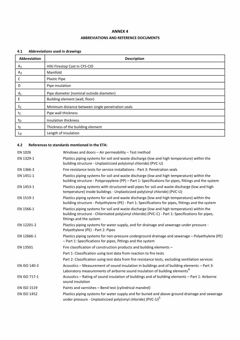
ABBREVIATIONS AND REFERENCE DOCUMENTS
4.1 Abbreviations used in drawings
Abbreviation Description
A1 Hilti Firestop Cast in CFS-CID
A2 Manifold
C Plastic Pipe
D Pipe insulation
dc Pipe diameter (nominal outside diameter)
E Building element (wall, floor)
S1 Minimum distance between single penetration seals
tC Pipe wall thickness
tD Insulation thickness
tE Thickness of the building element
LD Length of Insulation
4.2 References to standards mentioned in the ETA:
EN 1026 Windows and doors – Air permeability – Test method
EN 1329-1 Plastics piping systems for soil and waste discharge (low and high temperature) within the
building structure - Unplasticized poly(vinyl chloride) (PVC-U)
EN 1366-3 Fire resistance tests for service installations - Part 3: Penetration seals
EN 1451-1 Plastics piping systems for soil and waste discharge (low and high temperature) within the
building structure - Polypropylene (PP) – Part 1: Specifications for pipes, fittings and the system
EN 1453-1 Plastics piping systems with structured-wall pipes for soil and waste discharge (low and high
temperature) inside buildings - Unplasticized poly(vinyl chloride) (PVC-U)
EN 1519-1 Plastics piping systems for soil and waste discharge (low and high temperature) within the
building structure - Polyethylene (PE) - Part 1: Specifications for pipes, fittings and the system
EN 1566-1 Plastics piping systems for soil and waste discharge (low and high temperature) within the
building structure - Chlorinated poly(vinyl chloride) (PVC-C) - Part 1: Specifications for pipes, fittings and the system
EN 12201-2 Plastics piping systems for water supply, and for drainage and sewerage under pressure -
Polyethylene (PE) - Part 2: Pipes
EN 12666-1 Plastics piping systems for non-pressure underground drainage and sewerage – Polyethylene (PE) – Part 1: Specifications for pipes, fittings and the system
EN 13501 Fire classification of construction products and building elements –
Part 1: Classification using test data from reaction to fire tests
Part 2: Classification using test data from fire resistance tests, excluding ventilation services
EN ISO 140-3 Acoustics – Measurement of sound insulation in buildings and of building elements – Part 3:
Laboratory measurements of airborne sound insulation of building elements4
EN ISO 717-1 Acoustics – Rating of sound insulation of buildings and of building elements – Part 1: Airborne
sound insulation
EN ISO 1519 Paints and varnishes – Bend test (cylindrical mandrel)
EN ISO 1452 Plastics piping systems for water supply and for buried and above-ground drainage and sewerage
under pressure - Unplasticized poly(vinyl chloride) (PVC-U)5
EN ISO 15493 Plastics piping systems for industrial applications - Acrylonitrile-butadiene-styrene (ABS), unplasticized poly(vinyl chloride) (PVC-U) and chlorinated poly(vinyl chloride) (PVC-C) - Specifications for components and the system; Metric series
EN ISO 15494 Plastics piping systems for industrial applications - Polybutene (PB), polyethylene (PE) and
polypropylene (PP) - Specifications for components and the system; Metric series
EN ISO 15874 Plastics piping systems for hot and cold water installations - Polypropylene (PP)
EN ISO 20140-10 Acoustics – Measurements of sound insulation in buildings and of building elements – Part 10:
Laboratory measurement of airborne sound insulation of small building elements4
DIN 8061 Unplasticized polyvinyl chloride (PVC-U) pipes - General quality requirements and testing
DIN 8062 Unplasticized polyvinyl chloride (PVC-U) pipes - Dimensions
DIN 8074 Polyethylene (PE) - Pipes PE 80, PE 100 - Dimensions
DIN 8075 Polyethylene (PE) pipes - PE 80, PE 100 - General quality requirements, testing
DIN 8077 Polypropylene (PP) pipes - PP-H, PP-B, PP-R, PP-RCT – Dimensions
DIN 8078 Polypropylene (PP) pipes - PP-H, PP-B, PP-R, PP-RCT - General quality requirements and testing
DIN 19531-10 Pipes and fittings made of unplasticized polyvinyl chloride (PVC-U) socket for waste and soil discharge systems inside buildings – Part 10: Fire behaviour, quality control and installation
recommendations
DIN 19535-10 High-density polyethylene (PE-HD) pipes and fittings for hot-water resistant waste and soil
discharge systems (HT) inside buildings – Part 10: Fire behaviour, quality control and installation
recommendations
4.3 Other reference documents EOTA TR 001 Determination of impact resistance of panels and panel assemblies EOTA TR 024 Characterisation, Aspects of Durability and Factory Production Control for Reactive Materials,
Components and Products
Recommended