This appliance shall be installed in accordance with:������������r’ ��� ���������� ����� ���������� ���������������� ������������������������� �� �������!"#$��� ��� ������� % AS/NZS 3000 W���������� ��� ��&��'�������(��������&���������� )'� ����������*� �+���� �����%� ��(����������*�(���+&������'��� ������ ��,
All Rinnai gas productsare A.G.A. certified.
RHFE-559FT RHFE-309FT
Energysaver® Space HeatersRHFE-309FTRHFE-559FTRHFE-561FT
Operation and Installation Manual
Please note:������& �*��� ���������� ����� ����� ���-�'������T��*�������.����� �������y,�
RHFE-561FT

Rinnai i Energysaver Operation & Installation Manual
This page is intentionally blank
Rinnai ii Energysaver Operation & Installation Manual
INSTALLATION RECORD ........................................................................................................................ 1INSTALLATION REQUIREMENTS .......................................................................................................... 2CERTIFICATION ....................................................................................................................................... 2CARTON CONTENTS .............................................................................................................................. 2ABOUT YOUR ENERGYSAVER .............................................................................................................. 3
Control Panel Layout - RHFE-309FT / RHFE-559FT / RHFE-561FT .............................................................. 3
SAFETY .................................................................................................................................................... 4FEATURES ............................................................................................................................................... 9CUSTOMER INFORMATION - OPERATING ......................................................................................... 10
To turn the unit ‘ON’ ....................................................................................................................................... 10
To turn the unit ‘OFF’ .................................................................................................................................... 10
Room Temperature Adjustment .................................................................................................................... 10
Economy Mode ............................................................................................................................................. 11
Child Lock ..................................................................................................................................................... 11
Fan Operation ................................................................................................................................................ 11
SETTING THE CLOCK ........................................................................................................................... 12Setting the Clock/Timers ................................................................................................................................ 12
Day light saving and time adjustment ............................................................................................................ 12
Setting the ON / OFF Timers ......................................................................................................................... 12
OPERATING THE TIMERS .................................................................................................................... 13Operating the Timers ..................................................................................................................................... 13
Set and Forget Operation .............................................................................................................................. 13
Override ......................................................................................................................................................... 13
OTHER OPERATING INFORMATION ................................................................................................... 14Pre-Heat ......................................................................................................................................................... 14
Humidifier Tray ............................................................................................................................................... 14
Vertical Louvre Adjustment ............................................................................................................................ 14
Outside Flue Terminal .................................................................................................................................... 14
CARE OF YOUR ENERGYSAVER ........................................................................................................ 15Cleaning ......................................................................................................................................................... 15
Fan Filter ........................................................................................................................................................ 15
Cleaning the Fan Filter ................................................................................................................................... 15
SAFETY DEVICES .................................................................................................................................. 16Overheat Switch: ............................................................................................................................................ 16
Fusible Links: ................................................................................................................................................. 16
Flame Failure Device: .................................................................................................................................... 16
Electrical Fuse: .............................................................................................................................................. 16
Power Failure: ................................................................................................................................................ 16
SERVICE ................................................................................................................................................. 16INSTALLATION MANUAL ...................................................................................................................... 18CONTACT DETAILS ............................................................................................................................... 33
TABLE OF CONTENTS

Rinnai 1 Energysaver Operation & Installation Manual
INSTALLATION RECORD
INSTALLERS / GAS FITTERS DETAILS
Installers Name: ________________________________________________________________________
Company Name: ________________________________________________________________________
Company Address: ________________________________________________________________________
________________________________________________________________________
________________________________________________________________________
Company Contact Details
Telephone: ________________________________________________________________________
Mobile Phone: ________________________________________________________________________
Certificate of Compliance / Certification Number: __________________________________________________
Authorised Persons - Licence Number: _________________________________________________________
Installers Signature: ________________________________________________________________________
Installation Date: ________________________________________________________________________
APPLIANCE DETAILS
Model Number: ________________________________________________________________________
Serial Number: ________________________________________________________________________
Installation Address: ________________________________________________________________________
________________________________________________________________________
________________________________________________________________________
________________________________________________________________________
Rinnai 2 Energysaver Operation & Installation Manual
INSTALLATION REQUIREMENTS
This heater must be installed by an authorised person. The installation must conform to local regulations.
The installation must also comply with the instructions supplied by Rinnai.
Service and removal must be carried out by an authorised person.
The Rinnai Energysaver® Range have been certified by the Australian Gas Association.
The AGA Certification Number is shown on the appliance dataplate.
No parts or functions should be modified or permanently removed from the heater.
Please keep these instructions in a safe place for future reference.
Check you have the following:
1 x Rinnai Space Heater - RHFE-309FT, RHFE-559FT or RHFE-561FT
1 x Rear Cover set, comprising of left, right and top cover panels
1 x Bolt pack containing;
• Stainless steel sheath clamp• 2 x securing brackets• 2 x 8g x 30 mm stainless steel securing bracket screws• 2 x plastic inlet hose clamps• 1 x 150 mm long cable tie• 1 x HD stainless steel flue clamp• 2 x 6g x 10 mm button head screws • 4 x 6g x 8 mm pan head screws.
CERTIFICATION
CARTON CONTENTS
Rinnai 3 Energysaver Operation & Installation Manual
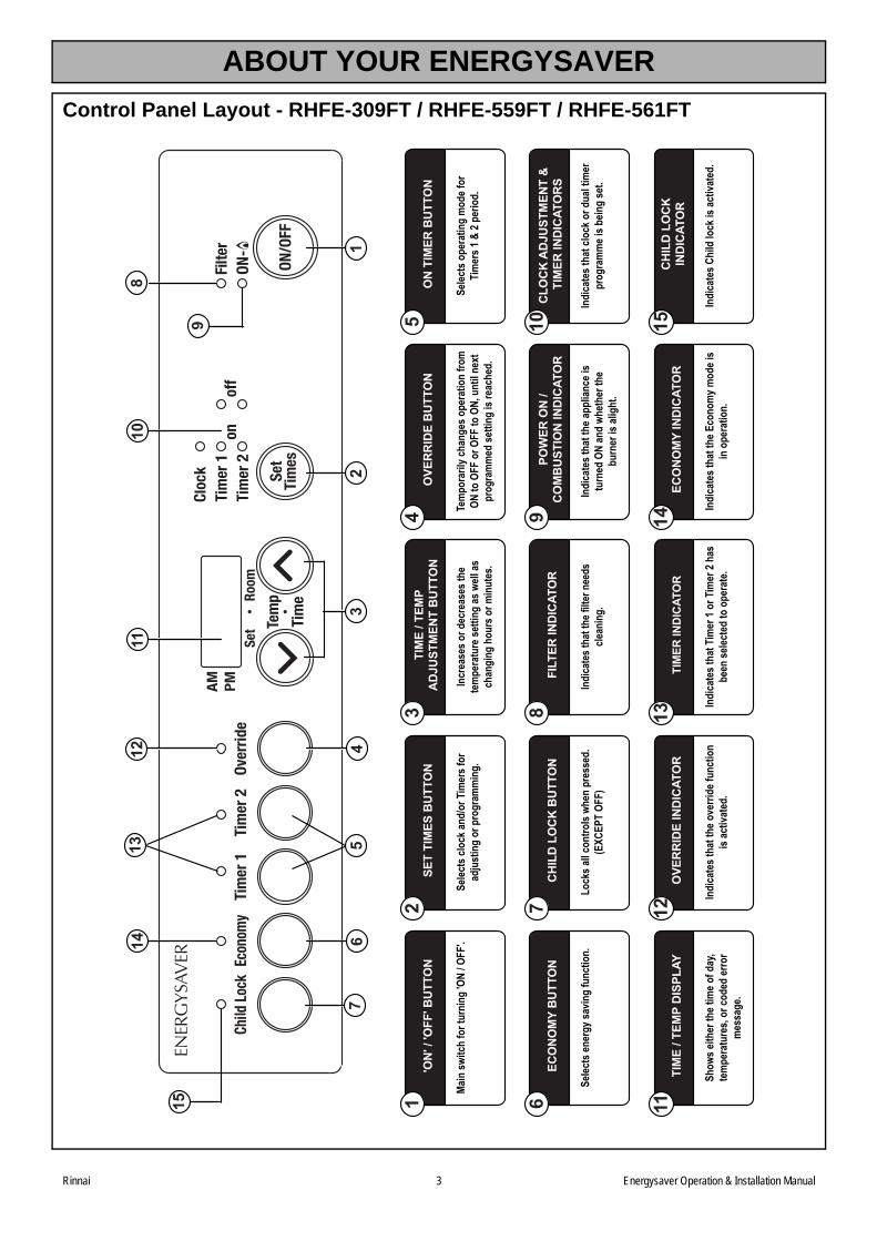
ABOUT YOUR ENERGYSAVER
Control Panel Layout - RHFE-309FT / RHFE-559FT / RHFE-561FT
Main
switc
h fo
r tur
ning
'ON
/ OFF
'.
'ON
' / 'O
FF' B
UTT
ON
1
12
37
5
8
159
1312
1411
10
64
Selec
ts cl
ock a
nd/o
r Tim
ers f
orad
just
ing
or p
rogr
amm
ing.
SET
TIM
ES B
UTT
ON
2
Incr
ease
s or d
ecre
ases
the
tem
pera
ture
setti
ng as
well
as
chan
ging
hou
rs o
r min
utes
.
TIM
E / T
EMP
AD
JUST
MEN
T B
UTT
ON
3
Tem
pora
rily c
hang
es o
pera
tion
from
ON to
OFF
or O
FF to
ON,
unt
il nex
tpr
ogra
mm
ed se
tting
is re
ache
d.
OVE
RR
IDE
BU
TTO
N4
Selec
ts o
pera
ting
mod
e for
Ti
mer
s 1 &
2 pe
riod.
ON
TIM
ER B
UTT
ON
5
Selec
ts en
ergy
savin
g fu
nctio
n.
ECO
NO
MY
BU
TTO
N6
Lock
s all c
ontro
ls wh
en p
ress
ed.
(EXC
EPT
OFF)
CH
ILD
LO
CK
BU
TTO
N7
Indi
cate
s tha
t the
filte
r nee
ds
clean
ing.
FILT
ER IN
DIC
ATO
R8
Indi
cate
s tha
t the
appl
iance
is
turn
ed O
N an
d wh
ethe
r the
bu
rner
is al
ight
.
POW
ER O
N /
CO
MB
UST
ION
IND
ICAT
OR
9
Indi
cate
s tha
t clo
ck o
r dua
l tim
er
prog
ram
me i
s bein
g se
t.
CLO
CK
AD
JUST
MEN
T &
TI
MER
IND
ICAT
OR
S10
Show
s eith
er th
e tim
e of d
ay,
tem
pera
ture
s, or
code
d er
ror
mes
sage
.
TIM
E / T
EMP
DIS
PLAY
11
Indi
cate
s tha
t the
ove
rride
func
tion
is ac
tivat
ed.
OVE
RR
IDE
IND
ICAT
OR
12
Indi
cate
s tha
t Tim
er 1
or T
imer
2 ha
s be
en se
lecte
d to
ope
rate
.
TIM
ER IN
DIC
ATO
R13
Indi
cate
s tha
t the
Eco
nom
y mod
e is
in o
pera
tion.
ECO
NO
MY
IND
ICAT
OR
14
Indi
cate
s Chi
ld lo
ck is
activ
ated
.
CH
ILD
LO
CK
IND
ICAT
OR
15
Rinnai 4 Energysaver Operation & Installation Manual
SAFETY
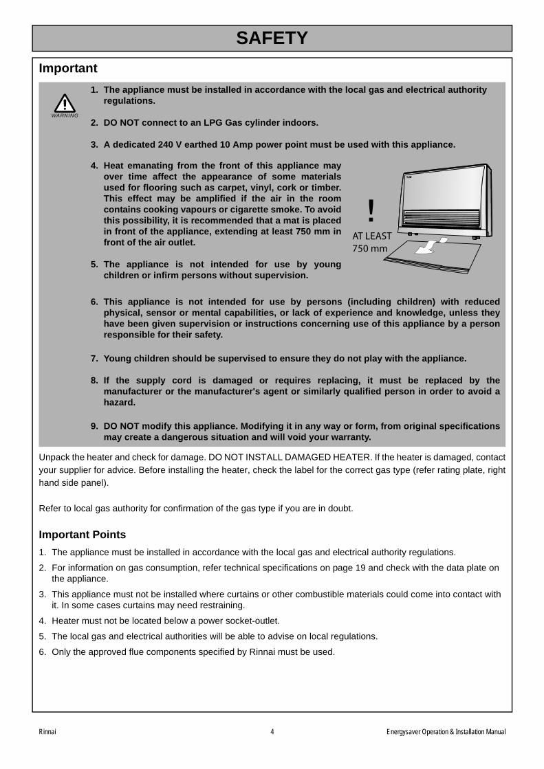
Important
Unpack the heater and check for damage. DO NOT INSTALL DAMAGED HEATER. If the heater is damaged, contact
your supplier for advice. Before installing the heater, check the label for the correct gas type (refer rating plate, right
hand side panel).
Refer to local gas authority for confirmation of the gas type if you are in doubt.
Important Points
1. The appliance must be installed in accordance with the local gas and electrical authority regulations.
2. For information on gas consumption, refer technical specifications on page 19 and check with the data plate on the appliance.
3. This appliance must not be installed where curtains or other combustible materials could come into contact with it. In some cases curtains may need restraining.
4. Heater must not be located below a power socket-outlet.
5. The local gas and electrical authorities will be able to advise on local regulations.
6. Only the approved flue components specified by Rinnai must be used.
1. The appliance must be installed in accordance with the local gas and electrical authority regulations.
2. DO NOT connect to an LPG Gas cylinder indoors.
3. A dedicated 240 V earthed 10 Amp power point must be used with this appliance.
4. Heat emanating from the front of this appliance mayover time affect the appearance of some materialsused for flooring such as carpet, vinyl, cork or timber.This effect may be amplified if the air in the roomcontains cooking vapours or cigarette smoke. To avoidthis possibility, it is recommended that a mat is placedin front of the appliance, extending at least 750 mm infront of the air outlet.
5. The appliance is not intended for use by youngchildren or infirm persons without supervision.
6. This appliance is not intended for use by persons (including children) with reducedphysical, sensor or mental capabilities, or lack of experience and knowledge, unless theyhave been given supervision or instructions concerning use of this appliance by a personresponsible for their safety.
7. Young children should be supervised to ensure they do not play with the appliance.
8. If the supply cord is damaged or requires replacing, it must be replaced by themanufacturer or the manufacturer's agent or similarly qualified person in order to avoid ahazard.
9. DO NOT modify this appliance. Modifying it in any way or form, from original specificationsmay create a dangerous situation and will void your warranty.
WARNING
AT LEAST750 mm
SAFETY
.
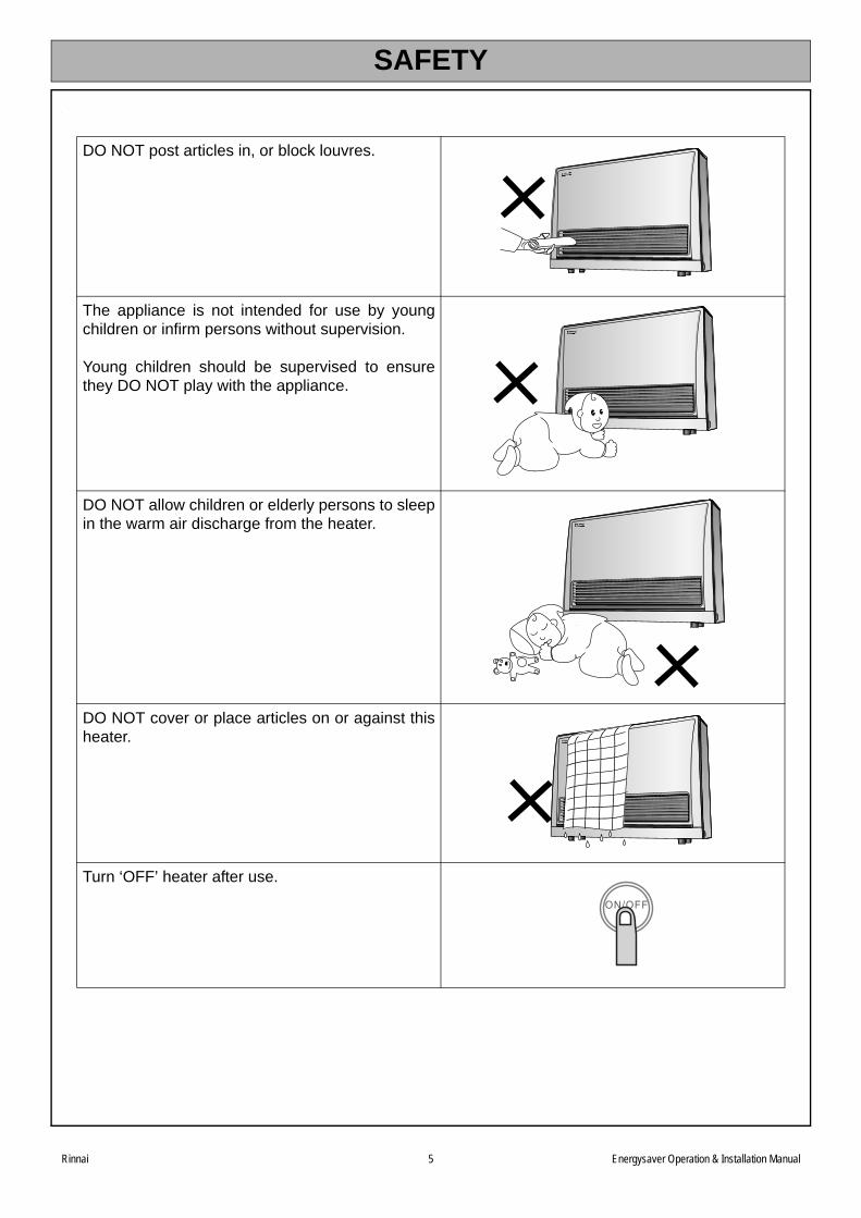
DO NOT post articles in, or block louvres.
The appliance is not intended for use by youngchildren or infirm persons without supervision.
Young children should be supervised to ensurethey DO NOT play with the appliance.
DO NOT allow children or elderly persons to sleepin the warm air discharge from the heater.
DO NOT cover or place articles on or against thisheater.
Turn ‘OFF’ heater after use.
Rinnai 5 Energysaver Operation & Installation Manual
SAFETY
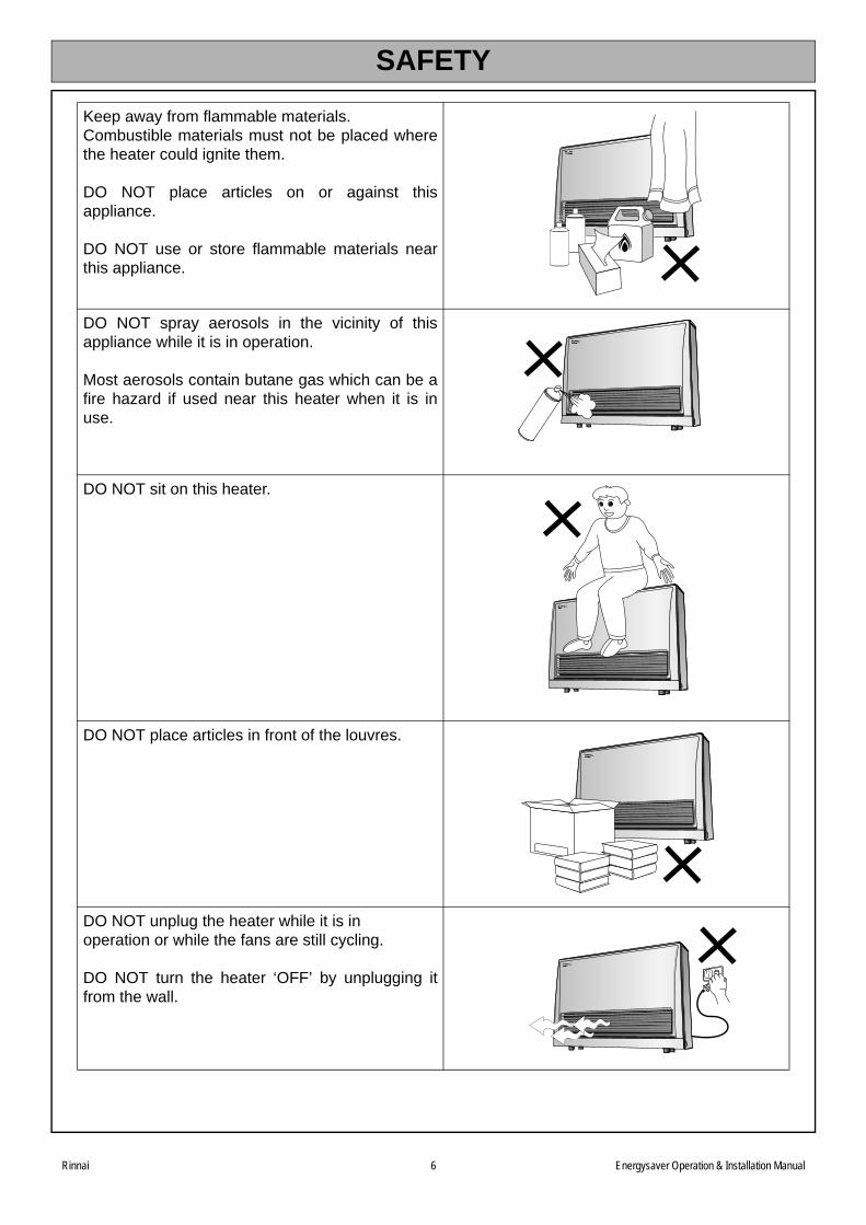
Keep away from flammable materials.Combustible materials must not be placed wherethe heater could ignite them.
DO NOT place articles on or against thisappliance.
DO NOT use or store flammable materials nearthis appliance.
DO NOT spray aerosols in the vicinity of thisappliance while it is in operation.
Most aerosols contain butane gas which can be afire hazard if used near this heater when it is inuse.
DO NOT sit on this heater.
DO NOT place articles in front of the louvres.
DO NOT unplug the heater while it is in operation or while the fans are still cycling.
DO NOT turn the heater ‘OFF’ by unplugging itfrom the wall.
Rinnai 6 Energysaver Operation & Installation Manual
SAFETY
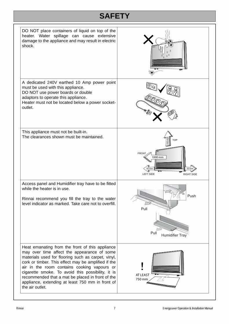
DO NOT place containers of liquid on top of theheater. Water spillage can cause extensivedamage to the appliance and may result in electricshock.
A dedicated 240V earthed 10 Amp power pointmust be used with this appliance.DO NOT use power boards or double adaptors to operate this appliance.Heater must not be located below a power socket-outlet.
This appliance must not be built-in. The clearances shown must be maintained.
Access panel and Humidifier tray have to be fittedwhile the heater is in use.
Rinnai recommend you fill the tray to the waterlevel indicator as marked. Take care not to overfill.
Heat emanating from the front of this appliancemay over time affect the appearance of somematerials used for flooring such as carpet, vinyl,cork or timber. This effect may be amplified if theair in the room contains cooking vapours orcigarette smoke. To avoid this possibility, it isrecommended that a mat be placed in front of theappliance, extending at least 750 mm in front ofthe air outlet.
2 50
mm
1000 mm
50 mm 50 mm
TOP
FRONT
LEFT SIDE RIGHT SIDE
Pull
Push
Pull Humidifier Tray
AT LEAST750 mm
Rinnai 7 Energysaver Operation & Installation Manual
SAFETY
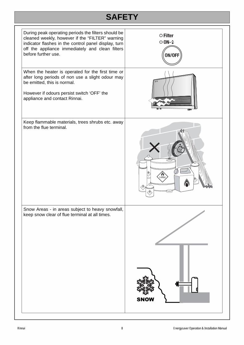
During peak operating periods the filters should becleaned weekly, however if the “FILTER” warningindicator flashes in the control panel display, turnoff the appliance immediately and clean filtersbefore further use.
When the heater is operated for the first time orafter long periods of non use a slight odour maybe emitted, this is normal.
However if odours persist switch ‘OFF’ the appliance and contact Rinnai.
Keep flammable materials, trees shrubs etc. awayfrom the flue terminal.
Snow Areas - in areas subject to heavy snowfall,keep snow clear of flue terminal at all times.
Rinnai 8 Energysaver Operation & Installation Manual

Rinnai 9 Energysaver Operation & Installation Manual
FEATURES
ROOM SEALED Air for combustion is taken from the outside and the flue products areexhausted to the outside. This means heater operation has no effect onthe composition and quality of air in the room.
PUSH BUTTON IGNITION Only one touch of the ‘ON’/’OFF’ button is required to operate theheater.
CHILD LOCK Prevents children from altering heater settings whilst running, or fromactivating the heater when turned ‘OFF’.
MEMORY The micro-computer records selected preset temperatures, the timesprogrammed into Timers as well as operating the Economy/Auto-Offand Pre-heat modes, to maintain comfort levels.
7 STEP AUTOMATIC HEAT CONTROL
Selected temperature is controlled via thermostat. The optimumcorresponding fan speeds are controlled by the Central ProcessingUnit.
PRE-HEAT This function will automatically operate the appliance before theprogrammed start time of the Timer, in order to heat a room to the pre-set temperature by the programmed start time.
ECONOMY MODE The Economy (ECON) function is an energy saving features designedto control the room temperature and prevent discomfort from overheating.
OVERRIDE FUNCTION This temporarily changes the heater operation from ‘ON’ to ‘OFF’, orvice versa, until the next programmed setting is reached.
DUAL WEEKDAY / WEEKEND TIMER
The Dual WEEKDAY/WEEKEND Timer allows you to program theappliance to come on for two separate periods each day, one period inthe morning and one period in the evening. The built in Pre-heat Modebrings the room temperature to the temperature you have selected, bythe time programmed into the Timer.
The Dual Timer feature means that you can "Set and Forget" yourheater. It will turn itself ‘ON’ or to STANDBY at the times you haveprogrammed until you cancel the Timer program.
FILTER INDICATOR When the fan filters become covered with dust, the filter indicator willflash. The filters should be vacuumed at regular intervals to avoidunnecessary strain on the appliance.
HUMIDIFIER TRAY The integral humidifier tray can be filled with water as required to raisethe humidity level in the room for extra comfort.Tray should not be filled to more than 3/4 full.
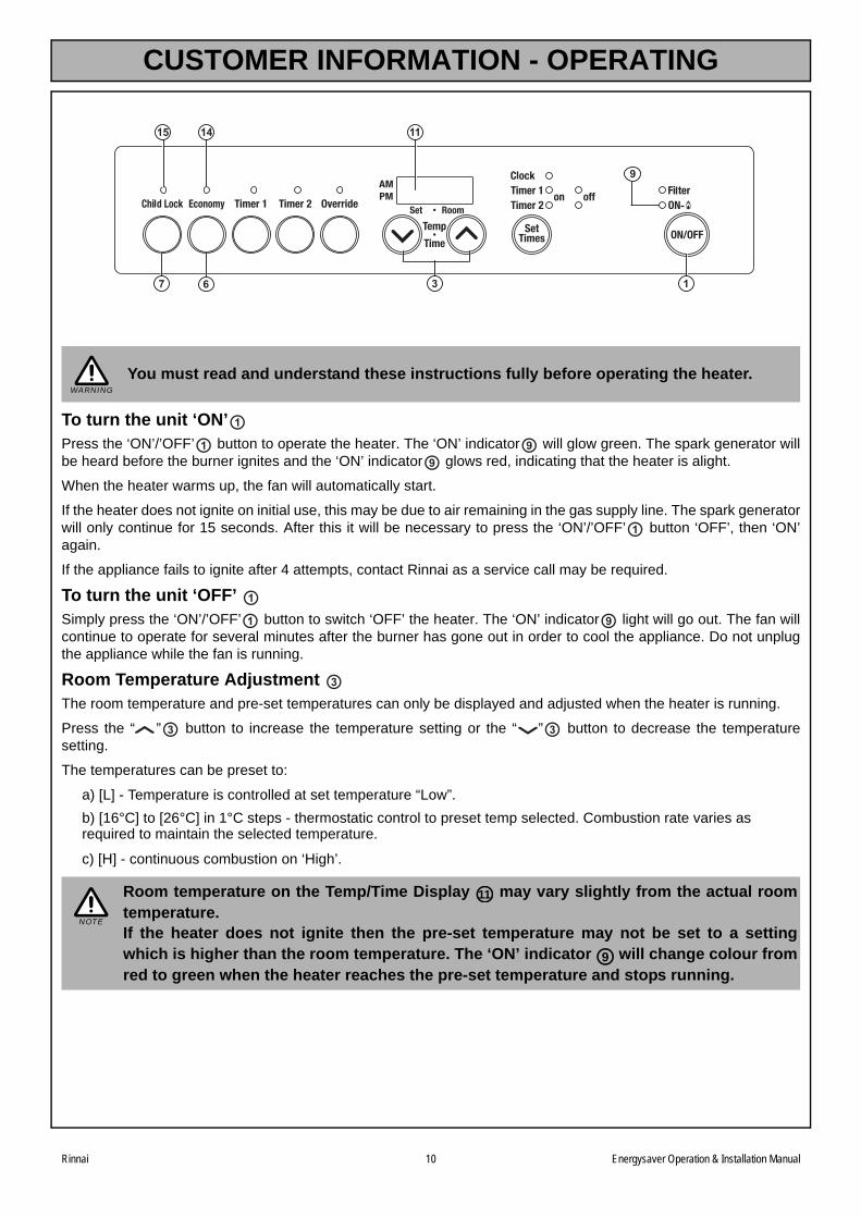
CUSTOMER INFORMATION - OPERATING
To turn the unit ‘ON’Press the ‘ON’/’OFF’ button to operate the heater. The ‘ON’ indicator will glow green. The spark generator willbe heard before the burner ignites and the ‘ON’ indicator glows red, indicating that the heater is alight.
When the heater warms up, the fan will automatically start.
If the heater does not ignite on initial use, this may be due to air remaining in the gas supply line. The spark generatorwill only continue for 15 seconds. After this it will be necessary to press the ‘ON’/’OFF’ button ‘OFF’, then ‘ON’again.
If the appliance fails to ignite after 4 attempts, contact Rinnai as a service call may be required.
To turn the unit ‘OFF’ Simply press the ‘ON’/’OFF’ button to switch ‘OFF’ the heater. The ‘ON’ indicator light will go out. The fan willcontinue to operate for several minutes after the burner has gone out in order to cool the appliance. Do not unplugthe appliance while the fan is running.
Room Temperature Adjustment The room temperature and pre-set temperatures can only be displayed and adjusted when the heater is running.
Press the “ ” button to increase the temperature setting or the “ ” button to decrease the temperaturesetting.
The temperatures can be preset to:
a) [L] - Temperature is controlled at set temperature “Low”.
b) [16°C] to [26°C] in 1°C steps - thermostatic control to preset temp selected. Combustion rate varies as required to maintain the selected temperature.
c) [H] - continuous combustion on ‘High’.
You must read and understand these instructions fully before operating the heater.
Room temperature on the Temp/Time Display may vary slightly from the actual roomtemperature.If the heater does not ignite then the pre-set temperature may not be set to a settingwhich is higher than the room temperature. The ‘ON’ indicator will change colour fromred to green when the heater reaches the pre-set temperature and stops running.
137
9
1415 11
6
WARNING
1
1 99
1
1
1 9
3
3 3
NOTE
11
9
Rinnai 10 Energysaver Operation & Installation Manual
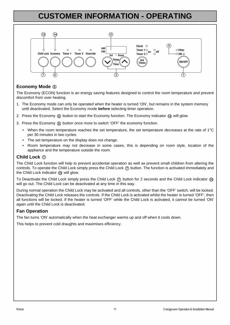
CUSTOMER INFORMATION - OPERATING
Economy Mode The Economy (ECON) function is an energy saving features designed to control the room temperature and preventdiscomfort from over heating.
1. The Economy mode can only be operated when the heater is turned ‘ON’, but remains in the system memory until deactivated. Select the Economy mode before selecting timer operation.
2. Press the Economy button to start the Economy function. The Economy indicator will glow.
3. Press the Economy button once more to switch ‘OFF’ the economy function.
• When the room temperature reaches the set temperature, the set temperature decreases at the rate of 1°Cper 30 minutes in two cycles.
• The set temperature on the display does not change.
• Room temperature may not decrease in some cases, this is depending on room style, location of theappliance and the temperature outside the room.
Child Lock The Child Lock function will help to prevent accidental operation as well as prevent small children from altering thecontrols. To operate the Child Lock simply press the Child Lock button. The function is activated immediately andthe Child Lock indicator will glow.
To Deactivate the Child Lock simply press the Child Lock button for 2 seconds and the Child Lock indicator will go out. The Child Lock can be deactivated at any time in this way.
During normal operation the Child Lock may be activated and all controls, other than the ‘OFF’ switch, will be locked.Deactivating the Child Lock releases the controls. If the Child Lock is activated whilst the heater is turned ‘OFF’, thenall functions will be locked. If the heater is turned ‘OFF’ while the Child Lock is activated, it cannot be turned ‘ON’again until the Child Lock is deactivated.
Fan OperationThe fan turns ‘ON’ automatically when the heat exchanger warms up and off when it cools down.
This helps to prevent cold draughts and maximises efficiency.
137
9
1415 11
6
6
6 14
6
7
715
7 15
Rinnai 11 Energysaver Operation & Installation Manual
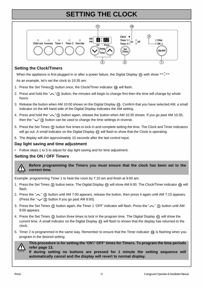
SETTING THE CLOCK
Setting the Clock/Timers
When the appliance is first plugged in or after a power failure, the Digital Display with show --:--As an example, let’s set the clock to 10:35 am:
1. Press the Set Times button once, the Clock/Timer indicator will flash.
2. Press and hold the “ ” button; the minutes will begin to change first then the time will change by whole hours.
3. Release the button when AM 10:00 shows on the Digital Display . Confirm that you have selected AM, a small indicator on the left hand side of the Digital Display indicates the AM setting.
4. Press and hold the “ ” button again, release the button when AM 10:35 shows. If you go past AM 10:35,
then the “ ” button can be used to change the time settings in reverse.
5. Press the Set Times button five times to lock in and complete setting the time. The Clock and Timer indicators
will go out. A small indicator on the Digital Display will flash to show that the Clock is operating.
6. The display will dim approximately 10 seconds after the last control input.
Day light saving and time adjustment
• Follow steps 1 to 5 to adjust for day light saving and for time adjustment.
Setting the ON / OFF Timers
Example: programming Timer 1 to heat the room by 7:10 am and finish at 9:00 am.
1. Press the Set Times button twice. The Digital Display will show AM 6:00. The Clock/Timer indicator will flash.
2. Press the “ ” button until AM 7:00 appears, release the button, then press it again until AM 7:10 appears.
(Press the “ ” button if you go past AM 8:00).
3. Press the Set Times button again, the Timer 1 ‘OFF’ indicator will flash. Press the “ ” button until AM 9:00 appears.
4. Press the Set Times button three times to lock in the program time. The Digital Display will show the
current time. A small indicator on the Digital Display will flash to shown that the display has returned to the clock.
5. Timer 2 is programmed in the same way. Remember to ensure that the Timer indicator is flashing when you
program in the desired setting.
Before programming the Timers you must ensure that the clock has been set to thecorrect time.
This procedure is for setting the ‘ON’/ ‘OFF’ times for Timers. To program the time periodsrefer page 13.If during setting no buttons are pressed for 1 minute the setting sequence willautomatically cancel and the display will revert to normal display.
123
9
11 10
11
2 10
3
11
3
3
2
11
NOTE
2 11 10
3
3
2 3
2 11
11
10
NOTE
Rinnai 12 Energysaver Operation & Installation Manual
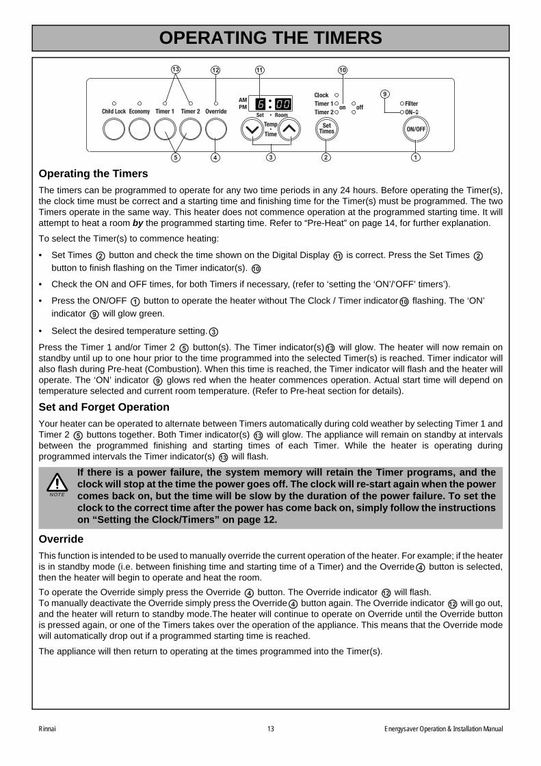
OPERATING THE TIMERS
Operating the Timers
The timers can be programmed to operate for any two time periods in any 24 hours. Before operating the Timer(s),the clock time must be correct and a starting time and finishing time for the Timer(s) must be programmed. The twoTimers operate in the same way. This heater does not commence operation at the programmed starting time. It willattempt to heat a room by the programmed starting time. Refer to “Pre-Heat” on page 14, for further explanation.
To select the Timer(s) to commence heating:
• Set Times button and check the time shown on the Digital Display is correct. Press the Set Times
button to finish flashing on the Timer indicator(s).
• Check the ON and OFF times, for both Timers if necessary, (refer to ‘setting the ‘ON’/‘OFF’ timers’).
• Press the ON/OFF button to operate the heater without The Clock / Timer indicator flashing. The ‘ON’
indicator will glow green.
• Select the desired temperature setting.
Press the Timer 1 and/or Timer 2 button(s). The Timer indicator(s) will glow. The heater will now remain onstandby until up to one hour prior to the time programmed into the selected Timer(s) is reached. Timer indicator willalso flash during Pre-heat (Combustion). When this time is reached, the Timer indicator will flash and the heater willoperate. The ‘ON’ indicator glows red when the heater commences operation. Actual start time will depend ontemperature selected and current room temperature. (Refer to Pre-heat section for details).
Set and Forget Operation
Your heater can be operated to alternate between Timers automatically during cold weather by selecting Timer 1 andTimer 2 buttons together. Both Timer indicator(s) will glow. The appliance will remain on standby at intervalsbetween the programmed finishing and starting times of each Timer. While the heater is operating duringprogrammed intervals the Timer indicator(s) will flash.
Override
This function is intended to be used to manually override the current operation of the heater. For example; if the heateris in standby mode (i.e. between finishing time and starting time of a Timer) and the Override button is selected,then the heater will begin to operate and heat the room.
To operate the Override simply press the Override button. The Override indicator will flash.To manually deactivate the Override simply press the Override button again. The Override indicator will go out,and the heater will return to standby mode.The heater will continue to operate on Override until the Override buttonis pressed again, or one of the Timers takes over the operation of the appliance. This means that the Override modewill automatically drop out if a programmed starting time is reached.
The appliance will then return to operating at the times programmed into the Timer(s).
If there is a power failure, the system memory will retain the Timer programs, and theclock will stop at the time the power goes off. The clock will re-start again when the powercomes back on, but the time will be slow by the duration of the power failure. To set theclock to the correct time after the power has come back on, simply follow the instructionson “Setting the Clock/Timers” on page 12.
2 11 2
10
1 10
9
3
5 13
9
5 13
13
NOTE
4
4 12
4 12
123
9
11 10
5
13 12
4
Rinnai 13 Energysaver Operation & Installation Manual
Rinnai 14 Energysaver Operation & Installation Manual
OTHER OPERATING INFORMATION
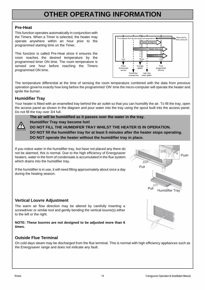
Pre-HeatThis function operates automatically in conjunction withthe Timers. When a Timer is selected, the heater mayoperate anywhere within an hour prior to theprogrammed starting time on the Timer.
This function is called Pre-Heat since it ensures theroom reaches the desired temperature by theprogrammed timer ON time. The room temperature issensed one hour before reaching the Timersprogrammed ON time.
The temperature differential at the time of sensing the room temperature combined with the data from previousoperation governs exactly how long before the programmed ‘ON’ time the micro-computer will operate the heater andignite the burner.
Humidifier TrayYour heater is fitted with an enamelled tray behind the air outlet so that you can humidify the air. To fill the tray, openthe access panel as shown in the diagram and pour water into the tray using the spout built into the access panel.Do not fill the tray over 3/4 full.
The air will be humidified as it passes over the water in the tray. Humidifier Tray may become hot! DO NOT FILL THE HUMIDIFER TRAY WHILST THE HEATER IS IN OPERATION. DO NOT fill the humidifier tray for at least 5 minutes after the heater stops operating.DO NOT operate the heater without the humidifier tray in place.
If you notice water in the humidifier tray, but have not placed any there donot be alarmed, this is normal. Due to the high efficiency of Energysaverheaters, water in the form of condensate is accumulated in the flue systemwhich drains into the humidifier tray.
If the humidifier is in use, it will need filling approximately about once a dayduring the heating season.
Vertical Louvre AdjustmentThe warm air flow direction may be altered by carefully inserting ascrewdriver or similar tool and gently bending the vertical louvre(s) eitherto the left or the right.
NOTE: These louvres are not designed to be adjusted more than 6times.
Outside Flue TerminalOn cold days steam may be discharged from the flue terminal. This is normal with high efficiency appliances such asthe Energysaver range and does not indicate any fault.
CAUTION
Pull
Push
Pull Humidifier Tray
Rinnai 15 Energysaver Operation & Installation Manual
CARE OF YOUR ENERGYSAVER
CleaningYour heater requires very little maintenance, but the following information will help you to keep it looking like newand working efficiently.
• Unplug electrical cord before cleaning.
• All parts of the heater can be cleaned using a soft, damp cloth and a mild detergent.
• DO NOT use solvents or abrasives to clean any parts.
Care for the Humidifier Tray: if the humidifier tray gets dirty, wash in warm soapy water.
How to clean: when heater is cold, remove the lower cover panel and pull out the humidifier tray from appliance.Ensure there is no water in the tray. If there is water in the tray, Keep the tray level to avoid spilling then wash inwarm soapy water.
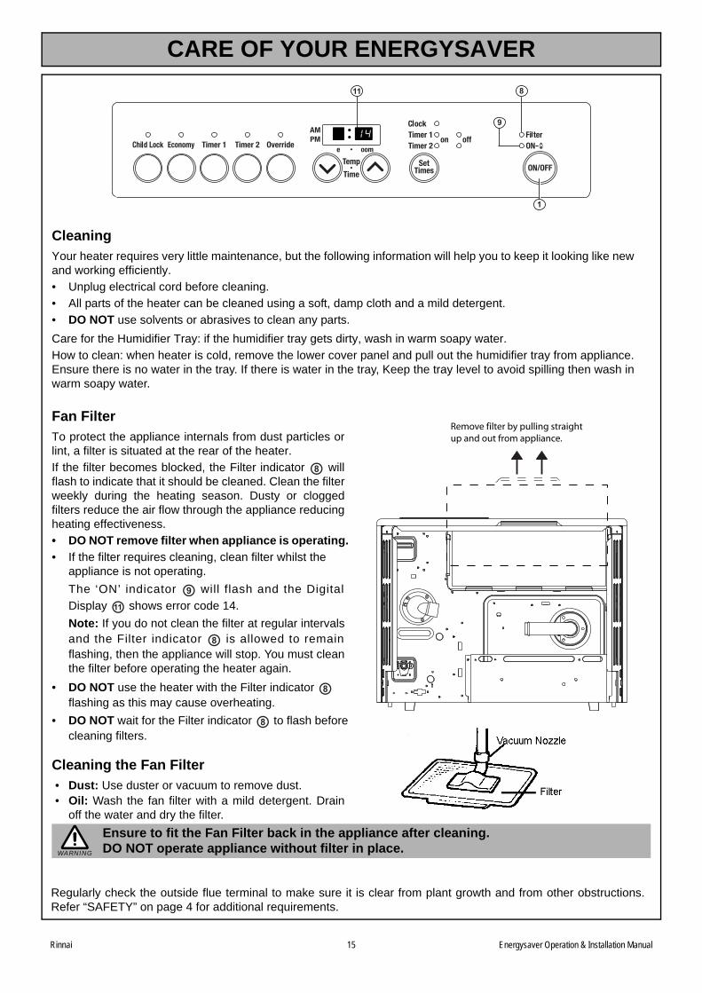
Fan Filter To protect the appliance internals from dust particles orlint, a filter is situated at the rear of the heater.
If the filter becomes blocked, the Filter indicator willflash to indicate that it should be cleaned. Clean the filterweekly during the heating season. Dusty or cloggedfilters reduce the air flow through the appliance reducingheating effectiveness.
• DO NOT remove filter when appliance is operating.
• If the filter requires cleaning, clean filter whilst the appliance is not operating.
The ‘ON’ indicator will flash and the Digital
Display shows error code 14.
Note: If you do not clean the filter at regular intervalsand the Filter indicator is allowed to remainflashing, then the appliance will stop. You must cleanthe filter before operating the heater again.
• DO NOT use the heater with the Filter indicator flashing as this may cause overheating.
• DO NOT wait for the Filter indicator to flash before cleaning filters.
Cleaning the Fan Filter• Dust: Use duster or vacuum to remove dust.• Oil: Wash the fan filter with a mild detergent. Drain
off the water and dry the filter.
Ensure to fit the Fan Filter back in the appliance after cleaning.DO NOT operate appliance without filter in place.
Regularly check the outside flue terminal to make sure it is clear from plant growth and from other obstructions.Refer “SAFETY” on page 4 for additional requirements.
1
8
9
11
8
9
11
8
8
8
Remove filter by pulling straight up and out from appliance.
WARNING
Rinnai 16 Energysaver Operation & Installation Manual
SAFETY DEVICES
Overheat Switch:This device automatically shuts the gas supply off if the heater exceeds a predetermined temperature.
This is normally caused by an obstruction in front of the louvres, or a blocked fan filter.If the overheat switch operates, turn the unit ‘OFF’, remove the obstruction (clean filters) and allow the unit cool offfor 10-15 minutes before re-operating.
Fusible Links:The fusible link activates under conditions of severe overheating and shuts off the gas supply.A service call will be required to repair the appliance.
Flame Failure Device:If the flame goes out during operation this device shuts off gas to the burner. To reset, turn the unit ‘OFF’, then ‘ON’again. If this happens repeatedly a service call is required.
Electrical Fuse:The electrical circuits are protected by an electric fuse. When the fuse blows, the heater will not operate. The fusemust be replaced by an authorised person.
Power Failure:In the event of a power failure or power cut, the gas valves will automatically close. After the power is re-instated theappliance will automatically re-start. The time of day will need to be reset to the correct current time (refer “Setting theClock/Timers” on page 12).
Rinnai has a nation wide service and spare parts network. Our service network personnel are fully trained andequipped to give the best service on your Rinnai appliance. If your appliance needs servicing, please refer to the backpage of this manual for contact details.
Rinnai recommends that this appliance is serviced every 2 years.
SERVICE

Rinnai 17 Energysaver Operation & Installation Manual
This page is intentionally blank

Rinnai 18 Energysaver Operation & Installation Manual
SPECIFICATIONS ................................................................................................................. 19
Specification Table ........................................................................................................ 19
DIMENSIONS ........................................................................................................................ 20
HEATER LOCATION ............................................................................................................ 23
Location ......................................................................................................................... 23
Gas Supply .................................................................................................................... 23
Purging the Gas Supply ................................................................................................ 23
Electrical Supply ............................................................................................................ 23
FLUE INSTALLATION CONFIGURATIONS ........................................................................ 24
FLUE POSITIONING ............................................................................................................. 25
Flue Terminal Location .................................................................................................. 25
HEATER INSTALLATION ..................................................................................................... 26
COMMISSIONING ................................................................................................................. 27
TROUBLE SHOOTING ......................................................................................................... 28
Trouble Shooting Check List ......................................................................................... 28
ERROR MESSAGES ............................................................................................................. 30
WIRING DIAGRAMS.............................................................................................................. 31
INSTALLATION & COMMISSIONING CHECKLIST ............................................................ 32
INSTALLATION MANUAL
Rinnai 19 Energysaver Operation & Installation Manual
SPECIFICATIONS
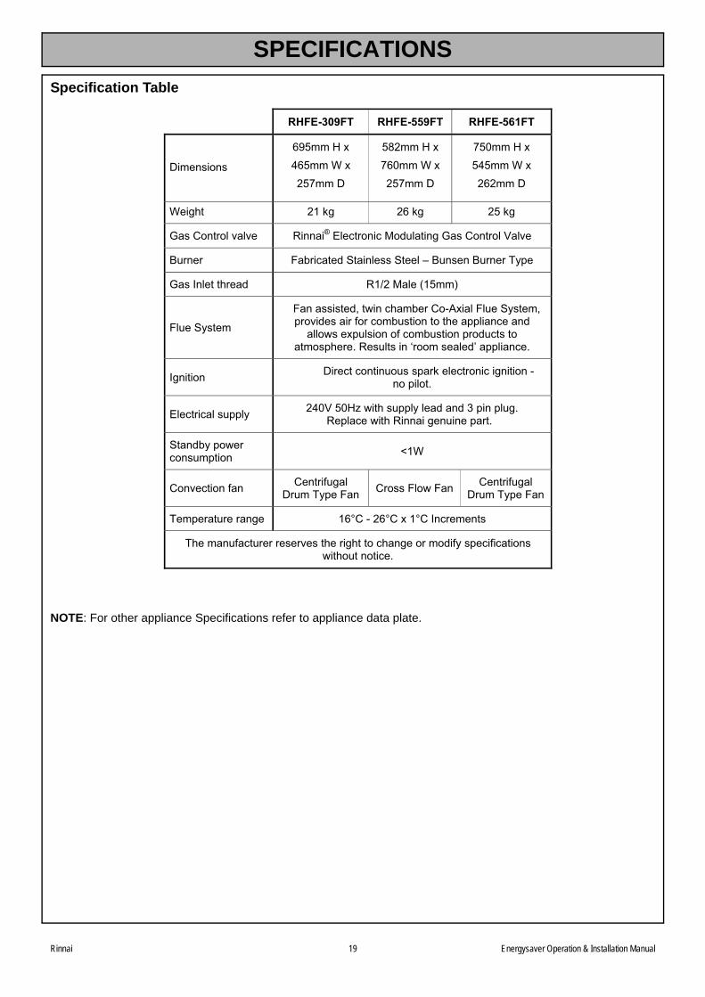
Specification Table
NOTE: For other appliance Specifications refer to appliance data plate.
� RHFE-309FT RHFE-559FT RHFE-561FT
����������
����� ��������������������
�
������ ��������������������
�
������ ��������������������
�
�������� ������ ����� ������
���������������� �����!�"��#����#�$%&�����������������'�����
(&����� )�*��#���%�+���������+�����,�(&�����(&�����-./��
����0����������%� �1��$����2����3�
)�&��+.�����
)����������%4��5���#���*����67�����)�&��+.����4�/���%�������8��#�*&������������//����#����%����5����/&�����8�#�*&�����/�%&#�����
����/����9� ��&�������:��������%;��//����#�9�
0������� ����#��#����&&���/�������#����#���������6����/���9�
"��#���#����&//�.� ���'��� <�5�����&//�.����%���%�=�/���/�&�9�� �/��#��5���� ���������&����/���9�
+���%*.�/5���#��&�/���� >���
����#����8��� ������8&�������&��-./��)��� �����)�5�)��� ������8&����
��&��-./��)���
-��/����&��������� �?��6��?�����?��0�#��������
-������&8�#�&�������������������������#���������%�8.��/�#�8�#������5���&�����#�9�
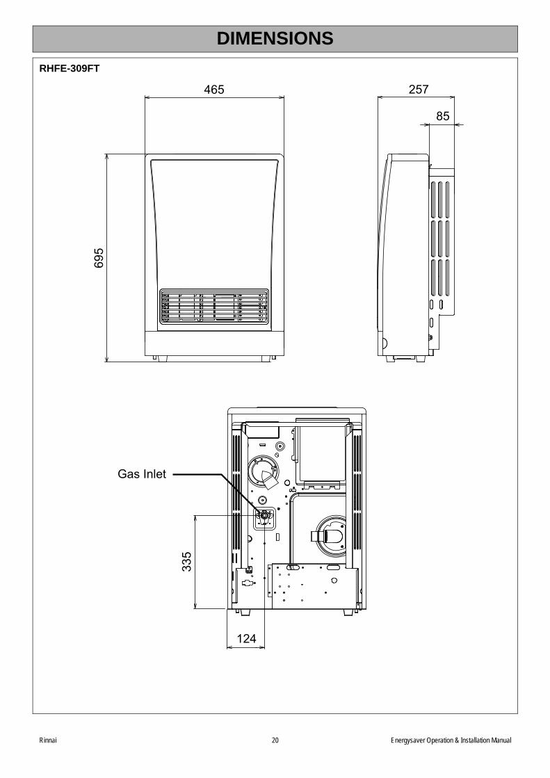
DIMENSIONS
RHFE-309FT
46569
5257
85
335
124
Gas Inlet
Rinnai 20 Energysaver Operation & Installation Manual
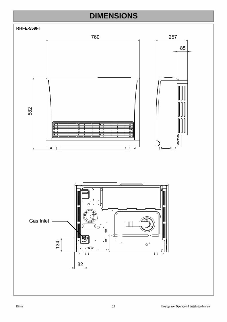
DIMENSIONS
RHFE-559FT
76058
2257
85
134
82
Gas Inlet
Rinnai 21 Energysaver Operation & Installation Manual
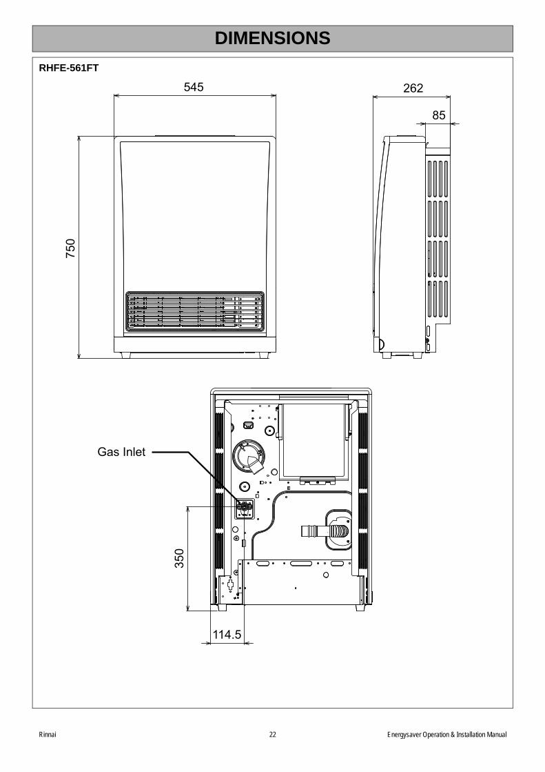
DIMENSIONS
RHFE-561FT
350
114.5
54575
0262
85
Gas Inlet
Rinnai 22 Energysaver Operation & Installation Manual
Rinnai 23 Energysaver Operation& Installation Manual
HEATER LOCATION
LocationWhen positioning the heater the main variables governing the location are Flueing and Warm Air Distribution.
This heater must not be installed where curtains or other combustible materials could come into contact with it. Insome cases curtains may need restraining. Refer to page 4 for additional safety consideration.
Gas SupplyThe gas supply terminates outside the heater at the rear of the appliance.
Locate the gas supply pipe to suit position as per the heater gas inlet. Refer to the drawings on pages 20, 21 and22 for appliance gas inlet location.
Gap required between the wall and heater body is 85 mm to 200 mm depending on Back Cover Kit used.
Purging the Gas SupplyAll foreign materials such as filings must be purged from the gas supply, as they may cause the gas control valveto malfunction.
Electrical SupplyThis heater has a power cord with a three pin plug supplied. The cord passes out of the rear of the appliance andcan extend to the left or right of the appliance.
A dedicated 240 V earthed 10 Amp power point must be used with this appliance. The power point must to the leftor the right side, it MUST NOT BE above the heater.
Alternatively the appliance can be direct wired if the power supply is to be concealed. The electric isolation switchMUST BE accessible after the appliance has been installed.
For all installations, ONLY Rinnai Energysaver Flue components MUST be used. The RinnaiEnergysaver MUST NOT be flued into ‘natural draft’ flue system or via a chimney.
Consult the Rinnai ‘Energysaver Space Heater Co-Axial flue System installation’ manualincluded with the ‘On Wall’ or ‘Direct’ flue kits for detailed flue installation instructions.
Gas pipe sizing must consider the gas input to this appliance as well as all other gasappliances in the premises. The gas meter and regulator must be specified for the total gasrate. Suitable sizing chart such as the one in AS/NZS 5601 should be used.
Consult a qualified electrician if direct wiring is required as it must comply with therequirements of AS/NZS 5601 and AS/NZS 3000 and any other relevant local regulations.
WARNING
WARNING
IMPORTANT
FLUE INSTALLATION CONFIGURATIONS
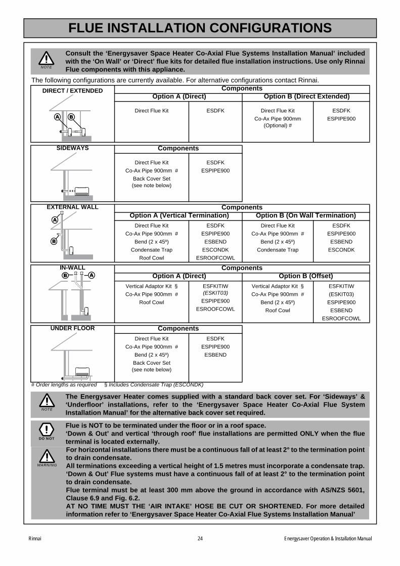
Consult the ‘Energysaver Space Heater Co-Axial Flue Systems Installation Manual’ includedwith the ‘On Wall’ or ‘Direct’ flue kits for detailed flue installation instructions. Use only RinnaiFlue components with this appliance.
The following configurations are currently available. For alternative configurations contact Rinnai.ComponentsDIRECT / EXTENDED
Option A (Direct) Option B (Direct Extended)
Direct Flue Kit ESDFK Direct Flue Kit
Co-Ax Pipe 900mm (Optional) #
ESDFK
ESPIPE900
SIDEWAYS Components
Direct Flue Kit
Co-Ax Pipe 900mm #
Back Cover Set (see note below)
ESDFK
ESPIPE900
EXTERNAL WALL Components Option A (Vertical Termination) Option B (On Wall Termination)
Direct Flue Kit
Co-Ax Pipe 900mm #
Bend (2 x 45º)
Condensate Trap
Roof Cowl
ESDFK
ESPIPE900
ESBEND
ESCONDK
ESROOFCOWL
Direct Flue Kit
Co-Ax Pipe 900mm #
Bend (2 x 45º)
Condensate Trap
ESDFK
ESPIPE900
ESBEND
ESCONDK
IN-WALL Components Option A (Direct) Option B (Offset)
Vertical Adaptor Kit §
Co-Ax Pipe 900mm #
Roof Cowl
ESFKITIW(ESKIT03)
ESPIPE900
ESROOFCOWL
Vertical Adaptor Kit §
Co-Ax Pipe 900mm #
Bend (2 x 45º)
Roof Cowl
ESFKITIW
(ESKIT03)
ESPIPE900
ESBEND
ESROOFCOWL
UNDER FLOOR Components
Direct Flue Kit
Co-Ax Pipe 900mm #
Bend (2 x 45º)
Back Cover Set(see note below)
ESDFK
ESPIPE900
ESBEND
# Order lengths as required § Includes Condensate Trap (ESCONDK)
The Energysaver Heater comes supplied with a standard back cover set. For ‘Sideways’ &‘Underfloor’ installations, refer to the ‘Energysaver Space Heater Co-Axial Flue SystemInstallation Manual’ for the alternative back cover set required.
Flue is NOT to be terminated under the floor or in a roof space.‘Down & Out’ and vertical ‘through roof’ flue installations are permitted ONLY when the flueterminal is located externally.For horizontal installations there must be a continuous fall of at least 2° to the termination pointto drain condensate.All terminations exceeding a vertical height of 1.5 metres must incorporate a condensate trap.‘Down & Out’ Flue systems must have a continuous fall of at least 2° to the termination pointto drain condensate. Flue terminal must be at least 300 mm above the ground in accordance with AS/NZS 5601,Clause 6.9 and Fig. 6.2.AT NO TIME MUST THE ‘AIR INTAKE’ HOSE BE CUT OR SHORTENED. For more detailedinformation refer to ‘Energysaver Space Heater Co-Axial Flue Systems Installation Manual’
NOTE
NOTE
DO NOT
WARNING
Rinnai 24 Energysaver Operation & Installation Manual
FLUE POSITIONING
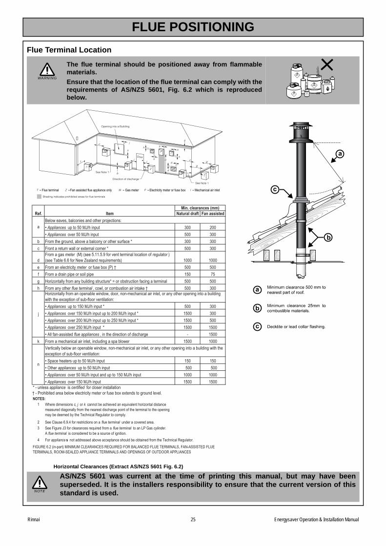
Flue Terminal Location
The flue terminal should be positioned away from flammablematerials.
Ensure that the location of the flue terminal can comply with therequirements of AS/NZS 5601, Fig. 6.2 which is reproducedbelow.
Horizontal Clearances (Extract AS/NZS 5601 Fig. 6.2)
AS/NZS 5601 was current at the time of printing this manual, but may have beensuperseded. It is the installers responsibility to ensure that the current version of thisstandard is used.
WARNING
Flue terminal Fan assisted flue appliance only Gas meter Electricity meter or fuse box Mechanical air inlet
Natural draft Fan assisted
��Appliances ����������� ������ � ���Appliances ���������� ������ � �
b ������ ������������������������������� ������!����" � �� ���������������#��������$��������������" � �
������������meter �%&�%�����'(('�')�!���������������������������!�regulator &%����*�����+'+�!���,�#�-���������.���������& ( (
� ��������������������meter ����!������$�%/&�0 � �! ������������������������������ (� 1�� 2���3��������!��������������������������"�4����������������!���������������� � � ����������� ���flue terminal ����#�������������������������5��0 � �
��Appliances �������(���� �������" � ���Appliances ������(���� ����������������� �������" (� ���Appliances ���������� ������������������ �������" (� ���Appliances ����������� ��������" (� (���6���!��7���������flue appliances ������ �������������!����� ���� 7 (�
5 ���������� �������������������������������������#�� (� (
��8����� ����������������� ������ (� (���9� ���appliances ����������� ������ � ���Appliances ���������� �����������������(���� ������ ( (��Appliances ������(���� ������ (� (�
( : ���������������c, j ����k ������������� ����������.��������� ���3�����������������������������������!����� �������������� ������������!�� ��������������� ���������������������������� ��*�� ������;������������������'
2 8���=������+')'>�!��������������������� flue terminal ��������������������'3 8�������������!����������������.������!������ flue terminal ������@/�A���cylinder.
6�flue terminal ������������������������������!���������'>
Ref. Item
�
Min. clearances (mm)
B���#������������������������ ������C�������D
C
2���3��������!����������������#����#�����������7��� ��������������������������� ���������������������������#�� �� ���$���������!����7!����������������D
H��������������#�������������#����#�����7��� ��������������������������� ���������������������������#�� �� ���$���������!����7!����������������D
NOTES:0�7�/�� ����������������#����������������������!������$��$���������������������'
�IAJ;K�+'��%��7����&�I,IJ�=@K6;6,=K8�;KLJI;KN��9;�B6@6,=KN��@JK�*K;I,6@8���6,7688I8*KN��@JK�*K;I,6@8��;9978K6@KN�6//@I6,=K�*K;I,6@8�6,N�9/K,I,A8�9��9J*N99;�6//@I6,=K8
"�7��������appliance ����certified �!����������������������
����appliance s �������������������������������� �����������������!����� ��*�� ������;��������'
�
NOTE
Rinnai 25 Energysaver Operation & Installation Manual
HEATER INSTALLATION
1. UNPACKING THE APPLIANCE
The heater is supplied in one carton containing; Heater, Standard Rear Cover Set and Bolt Pack.
Remove all packaging materials. Check for damage. If any damage is evident DO NOT install or operate thisappliance. Contact your supplier for advice. Before installing the heater, check it is labelled for the correct gas type,(refer to the data label at the rear of the heater). Refer to the local gas authority for confirmation of gas type if youare in doubt.
The heater does not come supplied with flue components. These are purchased separately.
ONLY Rinnai Energysaver Co-Axial Flue System Flue components can be used with thisappliance.
240 VOLTS, RISK OF ELECTRICAL SHOCK! Ensure the appliance is disconnected from mains power.
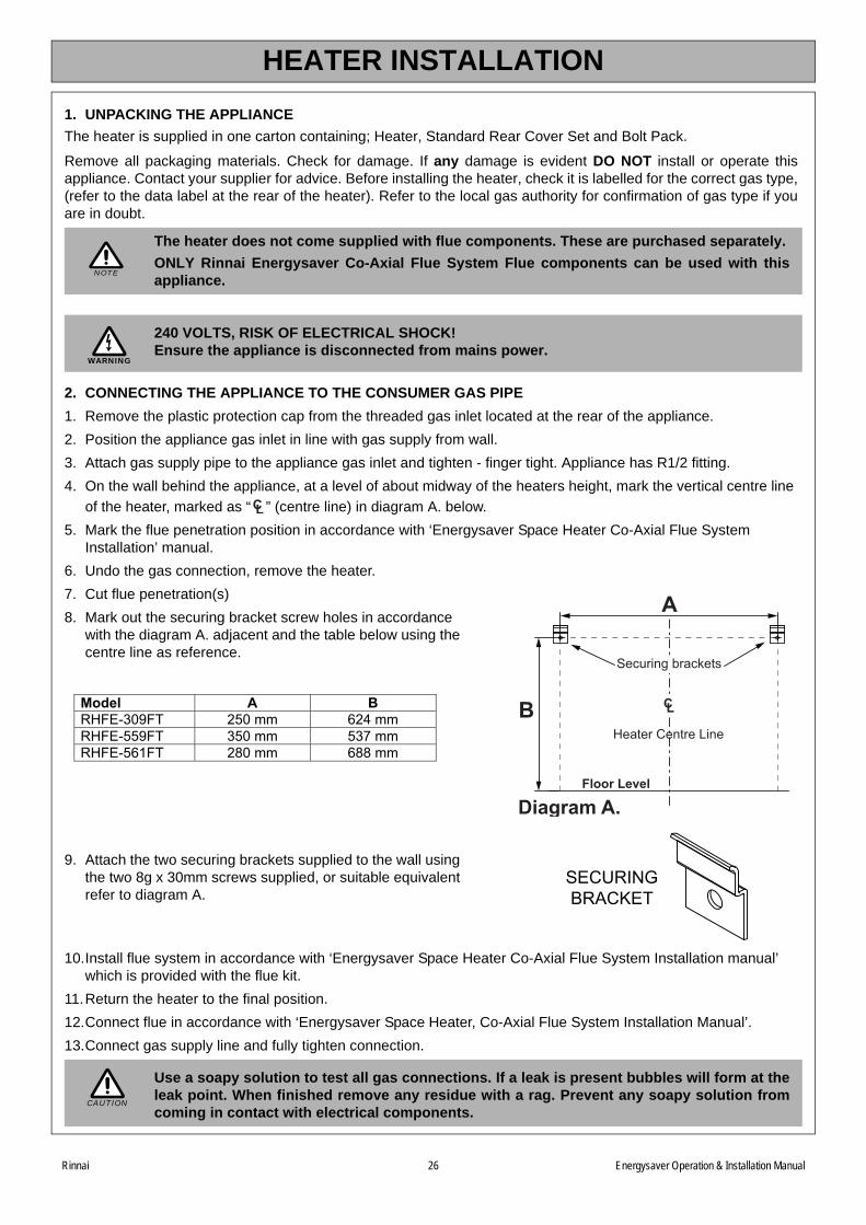
2. CONNECTING THE APPLIANCE TO THE CONSUMER GAS PIPE
1. Remove the plastic protection cap from the threaded gas inlet located at the rear of the appliance.
2. Position the appliance gas inlet in line with gas supply from wall.
3. Attach gas supply pipe to the appliance gas inlet and tighten - finger tight. Appliance has R1/2 fitting.
4. On the wall behind the appliance, at a level of about midway of the heaters height, mark the vertical centre line
of the heater, marked as “ ” (centre line) in diagram A. below.
5. Mark the flue penetration position in accordance with ‘Energysaver Space Heater Co-Axial Flue System Installation’ manual.
6. Undo the gas connection, remove the heater.
7. Cut flue penetration(s)
8. Mark out the securing bracket screw holes in accordance with the diagram A. adjacent and the table below using the centre line as reference.
9. Attach the two securing brackets supplied to the wall using the two 8g x 30mm screws supplied, or suitable equivalent refer to diagram A.
10.Install flue system in accordance with ‘Energysaver Space Heater Co-Axial Flue System Installation manual’ which is provided with the flue kit.
11.Return the heater to the final position.
12.Connect flue in accordance with ‘Energysaver Space Heater, Co-Axial Flue System Installation Manual’.
13.Connect gas supply line and fully tighten connection.
Use a soapy solution to test all gas connections. If a leak is present bubbles will form at theleak point. When finished remove any residue with a rag. Prevent any soapy solution fromcoming in contact with electrical components.
NOTE
WARNING
CL
A
B CL
Floor Level
Heater Centre Line
Securing brackets
Diagram A.
Model A B RHFE-309FT 250 mm 624 mm RHFE-559FT 350 mm 537 mm RHFE-561FT 280 mm 688 mm
SECURINGBRACKET
CAUTION
Rinnai 26 Energysaver Operation & Installation Manual
HEATER INSTALLATION
For Commissioning Instructions, refer to the Commissioning sheet attached behind the front panel of this appliance.
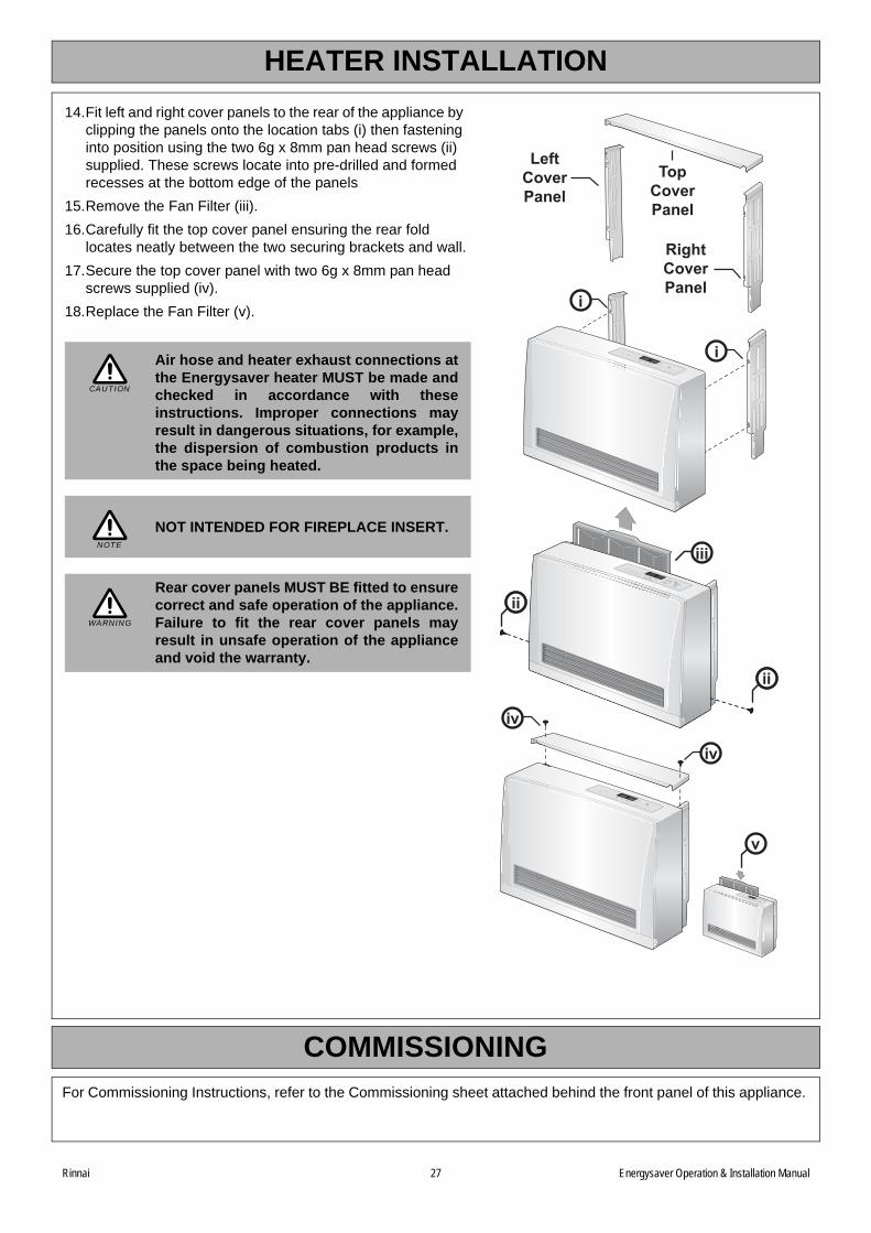
14.Fit left and right cover panels to the rear of the appliance by clipping the panels onto the location tabs (i) then fastening into position using the two 6g x 8mm pan head screws (ii) supplied. These screws locate into pre-drilled and formed recesses at the bottom edge of the panels
15.Remove the Fan Filter (iii).
16.Carefully fit the top cover panel ensuring the rear fold locates neatly between the two securing brackets and wall.
17.Secure the top cover panel with two 6g x 8mm pan head screws supplied (iv).
18.Replace the Fan Filter (v).
Air hose and heater exhaust connections atthe Energysaver heater MUST be made andchecked in accordance with theseinstructions. Improper connections mayresult in dangerous situations, for example,the dispersion of combustion products inthe space being heated.
NOT INTENDED FOR FIREPLACE INSERT.
Rear cover panels MUST BE fitted to ensurecorrect and safe operation of the appliance.Failure to fit the rear cover panels mayresult in unsafe operation of the applianceand void the warranty.
i
iv
iv
ii
ii
iv
iv
TopCoverPanel
RightCoverPanel
LeftCoverPanel
iii
v
i
CAUTION
NOTE
WARNING
COMMISSIONING
Rinnai 27 Energysaver Operation & Installation Manual
Rinnai 28 Energysaver Operation & Installation Manual
TROUBLE SHOOTING
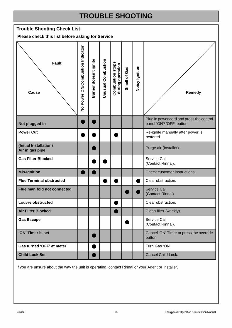
Trouble Shooting Check List
If you are unsure about the way the unit is operating, contact Rinnai or your Agent or Installer.
Please check this list before asking for Service
Fault
Cause
No
Po
wer
ON
/Co
mb
us
tio
n I
nd
ica
tor
Bu
rner
do
esn
’t i
gn
ite
Un
us
ual
Co
mb
us
tio
n
Co
mb
us
tio
n s
top
sd
uri
ng
op
era
tio
n
Sm
ell
of
Ga
s
No
isy
Ign
itio
n
Remedy
Not plugged inPlug in power cord and press the control panel ‘ON‘/ ‘OFF’ button.
Power Cut Re-ignite manually after power is restored.
(Initial Installation)Air in gas pipe
Purge air (Installer).
Gas Filter Blocked Service Call(Contact Rinnai).
Mis-Ignition Check customer instructions.
Flue Terminal obstructed Clear obstruction.
Flue manifold not connected Service Call(Contact Rinnai).
Louvre obstructed Clear obstruction.
Air Filter Blocked Clean filter (weekly).
Gas Escape Service Call(Contact Rinnai).
‘ON’ Timer is set Cancel ‘ON’ Timer or press the override button.
Gas turned ‘OFF’ at meter Turn Gas ‘ON’.
Child Lock Set Cancel Child Lock.
TROUBLE SHOOTING
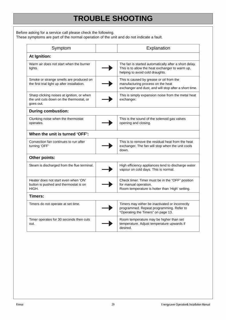
Before asking for a service call please check the following.These symptoms are part of the normal operation of the unit and do not indicate a fault.
Symptom Explanation
At Ignition:
Warm air does not start when the burner lights.
The fan is started automatically after a short delay. This is to allow the heat exchanger to warm up, helping to avoid cold draughts.
Smoke or strange smells are produced on the first trial light up after installation.
This is caused by grease or oil from the manufacturing process on the heat exchanger and dust, and will stop after a short time.
Sharp clicking noises at ignition, or when the unit cuts down on the thermostat, or goes out.
This is simply expansion noise from the metal heat exchanger.
During combustion:
Clunking noise when the thermostat operates.
This is the sound of the solenoid gas valves opening and closing.
When the unit is turned ‘OFF’:
Convection fan continues to run after turning ‘OFF’
This is to remove the residual heat from the heat exchanger. The fan will stop when the unit cools down.
Other points:
Steam is discharged from the flue terminal. High efficiency appliances tend to discharge water vapour on cold days. This is normal.
Heater does not start even when ‘ON’ button is pushed and thermostat is on HIGH.
Check timer. Timer must be in the “OFF” position for manual operation.Room temperature is hotter than ‘High’ setting.
Timers:
Timers do not operate at set time. Timers may either be inactivated or incorrectly programmed. Repeat programming. Refer to “Operating the Timers” on page 13.
Timer operates for 30 seconds then cuts out.
Room temperature may be higher than set temperature. Adjust temperature upwards if desired.
Rinnai 29 Energysaver Operation& Installation Manual
ERROR MESSAGES
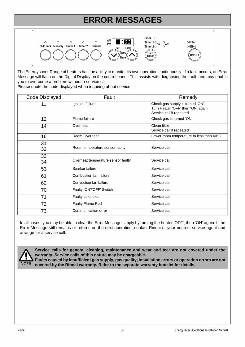
The Energysaver Range of heaters has the ability to monitor its own operation continuously. If a fault occurs, an ErrorMessage will flash on the Digital Display on the control panel. This assists with diagnosing the fault, and may enableyou to overcome a problem without a service call. Please quote the code displayed when inquiring about service.
Code Displayed Fault Remedy
11 Ignition failure Check gas supply is turned ‘ON’Turn Heater ‘OFF’ then ‘ON’ againService call if repeated
12 Flame failure Check gas is turned ‘ON’
14 Overheat Clean filterService call if repeated
16 Room Overheat Lower room temperature to less than 40°C
3132 Room temperature sensor faulty Service call
3334 Overheat temperature sensor faulty Service call
53 Sparker failure Service call
61 Combustion fan failure Service call
62 Convection fan failure Service call
70 Faulty ‘ON’/’OFF’ Switch Service call
71 Faulty solenoids Service call
72 Faulty Flame Rod Service call
73 Communication error Service call
In all cases, you may be able to clear the Error Message simply by turning the heater ‘OFF’, then ‘ON’ again. If theError Message still remains or returns on the next operation, contact Rinnai or your nearest service agent andarrange for a service call.
Service calls for general cleaning, maintenance and wear and tear are not covered under thewarranty. Service calls of this nature may be chargeable.Faults caused by insufficient gas supply, gas quality, installation errors or operation errors are notcovered by the Rinnai warranty. Refer to the separate warranty booklet for details.NOTE
Rinnai 30 Energysaver Operation& Installation Manual
Rinnai 31 Energysaver Operation & Installation Manual
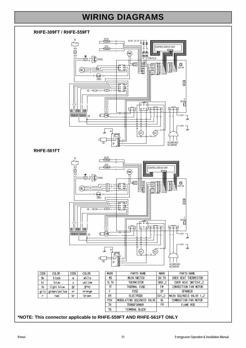
*NOTE: This connector applicable to RHFE-559FT AND RHFE-561FT ONLY
CONTROL DISPLAY UNIT
rr
r
bl
WW
OH.TH
R.THyy
TEST SW31
TF
OHS1
12
1
yy
9
1
wER SP
gr/y
gyorblr
SV1 SV2
gr/y
3AF
FR
MS
10
OHS2
bl
w w
rbk
ybkrw
br
AC240V:AUSAC230V:NZ
lbgy gyww
31
w
gr/y
TR
bl
2 1 4 1 3
1
18
1
4
3
1
4
3
6
6
1 4
1
5
8 4
1
wybk
ygyor
ry rblbkbrbr
ww
w
wbl
blblw
rbky
bk
CONTROL DISPLAY UNIT
rr
r
bl
WW
OH.TH
R.THyy
TEST SW3
1
TF
OHS1
12
1
yy
1
8
wER SP
gr/y
gyorblr
SV1 SV2
gr/y
3AF
FR
MS
10
OHS2
bl
w w
rbk
rbkyw
br
AC240V:AUSAC230V:NZ
lbgy gyww
3
1
w
gr/y
TR
bl
2 1 4 1 3
1
8
1
4
3
1
4
3
6
6
1 4
1
5
8 4
1
wybk
ygyor
ry rblbkbrbr
ww
w
wbl
blbl
bk
1
3
SUB-P.C.B.wbl
bk
TBAC24V
r
bk
RHFE-309FT / RHFE-559FT
RHFE-561FT
WIRING DIAGRAMS
Rinnai 32 Energysaver Operation & Installation Manual
INSTALLATION & COMMISSIONING CHECKLIST
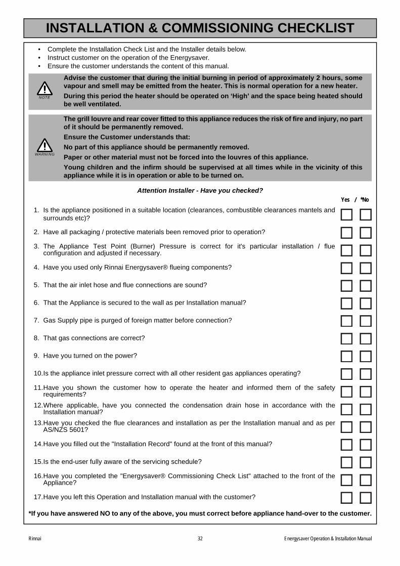
• Complete the Installation Check List and the Installer details below.• Instruct customer on the operation of the Energysaver.• Ensure the customer understands the content of this manual.
Attention Installer - Have you checked?
*If you have answered NO to any of the above, you must correct before appliance hand-over to the customer.
Advise the customer that during the initial burning in period of approximately 2 hours, somevapour and smell may be emitted from the heater. This is normal operation for a new heater.
During this period the heater should be operated on ‘High’ and the space being heated shouldbe well ventilated.
The grill louvre and rear cover fitted to this appliance reduces the risk of fire and injury, no partof it should be permanently removed.
Ensure the Customer understands that:
No part of this appliance should be permanently removed.
Paper or other material must not be forced into the louvres of this appliance.
Young children and the infirm should be supervised at all times while in the vicinity of thisappliance while it is in operation or able to be turned on.
Yes / *No
1. Is the appliance positioned in a suitable location (clearances, combustible clearances mantels andsurrounds etc)?
2. Have all packaging / protective materials been removed prior to operation?
3. The Appliance Test Point (Burner) Pressure is correct for it's particular installation / flueconfiguration and adjusted if necessary.
4. Have you used only Rinnai Energysaver® flueing components?
5. That the air inlet hose and flue connections are sound?
6. That the Appliance is secured to the wall as per Installation manual?
7. Gas Supply pipe is purged of foreign matter before connection?
8. That gas connections are correct?
9. Have you turned on the power?
10.Is the appliance inlet pressure correct with all other resident gas appliances operating?
11.Have you shown the customer how to operate the heater and informed them of the safetyrequirements?
12.Where applicable, have you connected the condensation drain hose in accordance with theInstallation manual?
13.Have you checked the flue clearances and installation as per the Installation manual and as perAS/NZS 5601?
14.Have you filled out the "Installation Record" found at the front of this manual?
15.Is the end-user fully aware of the servicing schedule?
16.Have you completed the "Energysaver® Commissioning Check List" attached to the front of theAppliance?
17.Have you left this Operation and Installation manual with the customer?
NOTE
WARNING
CONTACT INFORMATION
Rinnai 33 Energysaver RHFE-561FT Operating & Installation Manual 12.007 Issue 3 - 6/3/13
CONTACT DETAILS
Head Office 10-11 Walker Street,Braeside, Victoria 3195P.O. Box 460Tel: (03) 9271 6625Fax: (03) 9271 6622
National Help Line
Tel: 1300 555 545* Fax: 1300 555 655*
*Cost of a local call Higher from mobile or public phones.
Australia Pty. Ltd. ABN 74 005 138 769 Internet: www.rinnai.com.au E-mail: [email protected]
RHF559-1152x04(00)
Rinnai has a nation wide service and spare parts network. Our service network personnel are fully trained and equipped to give the best service on your Rinnai appliance. If your appliance needs servicing, please contact Rinnai. Rinnai recommends that this appliance is serviced every 2 years.
Recommended