DesignEngineeringManufacturing
Conveying Knowledge, Workmanship, Solutions
ISO 9001Certified
ENGINEERING GUIDE
Screw Conveyors
Release Date 4.1.16

KWS pRofIlE
Founded in 1972, KWS Manufacturing Company, Ltd, is the leader in the design and manufacture of conveying equipment for the bulk material handling industry. Our primary Customers are power transmission distributors, end users, engineering firms, system suppliers and original equipment manufacturers (OEMs).
As an ISO 9001 certified manufacturer, KWS provides the highest quality equipment and service to our Customers. The KWS name stands for Knowledge, Workmanship and Solutions. Our large number of repeat Customers shows our commitment to Customer satisfaction. Our quality system ensures that your equipment is designed and manufactured to rigid specifications and validated by exceeding performance expectations.
We also offer complete system design and engineered solutions for our Customers. KWS is one of the largest conveyor manufacturers in North America and continues to grow every year.
KWS SCREW CoNVEYoR ENGINEERING GUIDE
Screw conveyors are a cost effective and reliable method of conveying bulk materials. Thousands of bulk materials are conveyed and processed daily utilizing screw conveyors. The KWS Screw Conveyor Engineering Guide is an excellent resource for understanding and designing screw conveyors. The engineering guide is easy to use, with descriptions of many bulk materials and their characteristics. Examples are provided to assist the screw conveyor designer on how to properly select a screw conveyor, determine horsepower and speed as well as choose the proper components for a specific application.
i
DesignEngineeringManufacturing
Screw Conveyor Engineering Guide
Table Of COnTenTs
SCrEw ConvEyor BaSiCS . . . . . . . . . . . . . . . . . . . . . . . . . . . . . . . . . . . . . . . . . . . . . 1
TypES of SCrEw ConvEyorS . . . . . . . . . . . . . . . . . . . . . . . . . . . . . . . . . . . . . . . . . . 2
Horizontal Screw Conveyors . . . . . . . . . . . . . . . . . . . . . . . . . . . . . . . . . . . . . . . . . . 2
inclined Screw Conveyors . . . . . . . . . . . . . . . . . . . . . . . . . . . . . . . . . . . . . . . . . . . . 3
pitch Efficiency . . . . . . . . . . . . . . . . . . . . . . . . . . . . . . . . . . . . . . . . . . . . . . . . . . . . . 4
Horsepower requirements . . . . . . . . . . . . . . . . . . . . . . . . . . . . . . . . . . . . . . . . . . . . 4
Upset Conditions . . . . . . . . . . . . . . . . . . . . . . . . . . . . . . . . . . . . . . . . . . . . . . . . . . . 4
Shaftless Screw Conveyors . . . . . . . . . . . . . . . . . . . . . . . . . . . . . . . . . . . . . . . . . . . 5
advantages of Shaftless Screw Conveyors . . . . . . . . . . . . . . . . . . . . . . . . . . . . 5
vertical Screw Conveyors . . . . . . . . . . . . . . . . . . . . . . . . . . . . . . . . . . . . . . . . . . . . 6
advantages of vertical Screw Conveyors . . . . . . . . . . . . . . . . . . . . . . . . . . . . . . 6
TypES of SCrEw fEEdErS . . . . . . . . . . . . . . . . . . . . . . . . . . . . . . . . . . . . . . . . . . . . . 7
Screw feeders . . . . . . . . . . . . . . . . . . . . . . . . . . . . . . . . . . . . . . . . . . . . . . . . . . . . . 7
variable or Stepped pitch . . . . . . . . . . . . . . . . . . . . . . . . . . . . . . . . . . . . . . . . . . . . . 7
Tapered outside diameter . . . . . . . . . . . . . . . . . . . . . . . . . . . . . . . . . . . . . . . . . . . . 8
Mass flow . . . . . . . . . . . . . . . . . . . . . . . . . . . . . . . . . . . . . . . . . . . . . . . . . . . . . . . . 8
Basic Screw feeder design . . . . . . . . . . . . . . . . . . . . . . . . . . . . . . . . . . . . . . . . . . . 9
feeder Shroud . . . . . . . . . . . . . . . . . . . . . . . . . . . . . . . . . . . . . . . . . . . . . . . . . . . . 10
Screw feeder Capacity and Speed . . . . . . . . . . . . . . . . . . . . . . . . . . . . . . . . . . . . 10
Screw feeder Horsepower requirements . . . . . . . . . . . . . . . . . . . . . . . . . . . . . . . 10
other Types of Screw feeders . . . . . . . . . . . . . . . . . . . . . . . . . . . . . . . . . . . . . . . . 11
Multiple diameter Screw feeder/Conveyor . . . . . . . . . . . . . . . . . . . . . . . . . . . . . . 11
Live Bottom Screw feeder . . . . . . . . . . . . . . . . . . . . . . . . . . . . . . . . . . . . . . . . . . . 11
inclined Screw feeders . . . . . . . . . . . . . . . . . . . . . . . . . . . . . . . . . . . . . . . . . . . . . 12
Basic inclined Screw feeder design . . . . . . . . . . . . . . . . . . . . . . . . . . . . . . . . 12
inclined Screw feeder Capacity and Speed . . . . . . . . . . . . . . . . . . . . . . . . . . 13
inclined Screw feeder Horsepower requirements . . . . . . . . . . . . . . . . . . . . . 13
inlet Length . . . . . . . . . . . . . . . . . . . . . . . . . . . . . . . . . . . . . . . . . . . . . . . . . . . . 13
flight pitch Changes . . . . . . . . . . . . . . . . . . . . . . . . . . . . . . . . . . . . . . . . . . . . . 13
DesignEngineeringManufacturing
ii
Screw Conveyor Engineering Guide
BULk MaTEriaL CHaraCTEriSTiCS . . . . . . . . . . . . . . . . . . . . . . . . . . . . . . . . . . . . . . 14
Maximum particle Size and Bulk Material Lump Size . . . . . . . . . . . . . . . . . . . . . . 14
Bulk density . . . . . . . . . . . . . . . . . . . . . . . . . . . . . . . . . . . . . . . . . . . . . . . . . . . . . . 14
% Trough Loading . . . . . . . . . . . . . . . . . . . . . . . . . . . . . . . . . . . . . . . . . . . . . . . . . 14
Material factor (Mf) . . . . . . . . . . . . . . . . . . . . . . . . . . . . . . . . . . . . . . . . . . . . . . . . 14
Component/Bearing Series . . . . . . . . . . . . . . . . . . . . . . . . . . . . . . . . . . . . . . . . . . 14
abrasiveness, Corrosiveness, flowability and Special Characteristics . . . . . . . . . 14
Bulk Material Lump Size . . . . . . . . . . . . . . . . . . . . . . . . . . . . . . . . . . . . . . . . . . . . 15
Bulk Material Lump Classification . . . . . . . . . . . . . . . . . . . . . . . . . . . . . . . . . . . . . 15
Class 1 . . . . . . . . . . . . . . . . . . . . . . . . . . . . . . . . . . . . . . . . . . . . . . . . . . . . . . . . . . 15
Class 2 . . . . . . . . . . . . . . . . . . . . . . . . . . . . . . . . . . . . . . . . . . . . . . . . . . . . . . . . . . 15
Class 3 . . . . . . . . . . . . . . . . . . . . . . . . . . . . . . . . . . . . . . . . . . . . . . . . . . . . . . . . . . 15
Lump Size ratio . . . . . . . . . . . . . . . . . . . . . . . . . . . . . . . . . . . . . . . . . . . . . . . . . . . 16
Trough Loading . . . . . . . . . . . . . . . . . . . . . . . . . . . . . . . . . . . . . . . . . . . . . . . . . . . 17
15% Trough Loading . . . . . . . . . . . . . . . . . . . . . . . . . . . . . . . . . . . . . . . . . . . . . . . 17
30%a Trough Loading . . . . . . . . . . . . . . . . . . . . . . . . . . . . . . . . . . . . . . . . . . . . . . 17
30%B Trough Loading . . . . . . . . . . . . . . . . . . . . . . . . . . . . . . . . . . . . . . . . . . . . . . 17
45% Trough Loading . . . . . . . . . . . . . . . . . . . . . . . . . . . . . . . . . . . . . . . . . . . . . . . 17
CoMponEnT / BEarinG SEriES . . . . . . . . . . . . . . . . . . . . . . . . . . . . . . . . . . . . . . . . . 18
Component Series . . . . . . . . . . . . . . . . . . . . . . . . . . . . . . . . . . . . . . . . . . . . . . . . . 18
Series a . . . . . . . . . . . . . . . . . . . . . . . . . . . . . . . . . . . . . . . . . . . . . . . . . . . . . . . . . 18
Series B . . . . . . . . . . . . . . . . . . . . . . . . . . . . . . . . . . . . . . . . . . . . . . . . . . . . . . . . . 18
Series C . . . . . . . . . . . . . . . . . . . . . . . . . . . . . . . . . . . . . . . . . . . . . . . . . . . . . . . . . 18
Series d . . . . . . . . . . . . . . . . . . . . . . . . . . . . . . . . . . . . . . . . . . . . . . . . . . . . . . . . . 18
Component Series Tables . . . . . . . . . . . . . . . . . . . . . . . . . . . . . . . . . . . . . . . . . . . 19
Series 1 . . . . . . . . . . . . . . . . . . . . . . . . . . . . . . . . . . . . . . . . . . . . . . . . . . . . . . . . . 20
Series 2 . . . . . . . . . . . . . . . . . . . . . . . . . . . . . . . . . . . . . . . . . . . . . . . . . . . . . . . . . 20
Series 3 . . . . . . . . . . . . . . . . . . . . . . . . . . . . . . . . . . . . . . . . . . . . . . . . . . . . . . . . . 20
Series 4 . . . . . . . . . . . . . . . . . . . . . . . . . . . . . . . . . . . . . . . . . . . . . . . . . . . . . . . . . 20
Table Of COnTenTs
iii
DesignEngineeringManufacturing
Screw Conveyor Engineering Guide
Table Of COnTenTs
faCTorS infLUEnCinG SCrEw ConvEyor dESiGn . . . . . . . . . . . . . . . . . . . . . . . 21
abrasiveness, Corrosiveness and flowability . . . . . . . . . . . . . . . . . . . . . . . . . . . . 21
Special Characteristics notes . . . . . . . . . . . . . . . . . . . . . . . . . . . . . . . . . . . . . . . . 21
abrasive Bulk Materials . . . . . . . . . . . . . . . . . . . . . . . . . . . . . . . . . . . . . . . . . . . . . 22
Highly Corrosive . . . . . . . . . . . . . . . . . . . . . . . . . . . . . . . . . . . . . . . . . . . . . . . . . . . 22
Mildly Corrosive . . . . . . . . . . . . . . . . . . . . . . . . . . . . . . . . . . . . . . . . . . . . . . . . . . . 22
Builds Up and Hardens (a) . . . . . . . . . . . . . . . . . . . . . . . . . . . . . . . . . . . . . . . . . . . 22
Generates Static Electricity (B) . . . . . . . . . . . . . . . . . . . . . . . . . . . . . . . . . . . . . . . . 23
decomposes – deteriorates in Storage (C) . . . . . . . . . . . . . . . . . . . . . . . . . . . . . . 23
flammability (d) . . . . . . . . . . . . . . . . . . . . . . . . . . . . . . . . . . . . . . . . . . . . . . . . . . . 23
Becomes plastic or Tends to Soften (E) . . . . . . . . . . . . . . . . . . . . . . . . . . . . . . . . . 23
very dusty (f) . . . . . . . . . . . . . . . . . . . . . . . . . . . . . . . . . . . . . . . . . . . . . . . . . . . . . 24
aerates and Becomes fluid (G) . . . . . . . . . . . . . . . . . . . . . . . . . . . . . . . . . . . . . . . 24
Explosiveness (H) . . . . . . . . . . . . . . . . . . . . . . . . . . . . . . . . . . . . . . . . . . . . . . . . . . 24
Stickiness - adhesion (i) . . . . . . . . . . . . . . . . . . . . . . . . . . . . . . . . . . . . . . . . . . . . . 24
Contaminable, affecting Use (J) . . . . . . . . . . . . . . . . . . . . . . . . . . . . . . . . . . . . . . . 25
degradable, affecting Use (k) . . . . . . . . . . . . . . . . . . . . . . . . . . . . . . . . . . . . . . . . 25
Gives off Harmful or Toxic Gas or fumes (L) . . . . . . . . . . . . . . . . . . . . . . . . . . . . . 25
Hygroscopic (M) . . . . . . . . . . . . . . . . . . . . . . . . . . . . . . . . . . . . . . . . . . . . . . . . . . . 25
interlocks, Mats or agglomerates (n) . . . . . . . . . . . . . . . . . . . . . . . . . . . . . . . . . . . 25
oils present (o) . . . . . . . . . . . . . . . . . . . . . . . . . . . . . . . . . . . . . . . . . . . . . . . . . . . 26
packs Under pressure (p) . . . . . . . . . . . . . . . . . . . . . . . . . . . . . . . . . . . . . . . . . . . 26
very Light and fluffy (Q) . . . . . . . . . . . . . . . . . . . . . . . . . . . . . . . . . . . . . . . . . . . . . 26
Elevated Temperature (r) . . . . . . . . . . . . . . . . . . . . . . . . . . . . . . . . . . . . . . . . . . . . 26
May Be Conveyed in a vertical Screw Conveyor (v) . . . . . . . . . . . . . . . . . . . . . . . 26
BULk MaTEriaL TaBLE . . . . . . . . . . . . . . . . . . . . . . . . . . . . . . . . . . . . . . . . . . . . . . . . . 27

DesignEngineeringManufacturing
iv
Screw Conveyor Engineering Guide
SCrEw ConvEyor CapaCiTy . . . . . . . . . . . . . . . . . . . . . . . . . . . . . . . . . . . . . . . . . . 42
Calculation of Conveyor Speed . . . . . . . . . . . . . . . . . . . . . . . . . . . . . . . . . . . . . . . 42
Capacity factors for Special pitches . . . . . . . . . . . . . . . . . . . . . . . . . . . . . . . . . . . 43
Capacity factors for Modified flight . . . . . . . . . . . . . . . . . . . . . . . . . . . . . . . . . . . 43
Example . . . . . . . . . . . . . . . . . . . . . . . . . . . . . . . . . . . . . . . . . . . . . . . . . . . . . . . . . 44
Capacity Table . . . . . . . . . . . . . . . . . . . . . . . . . . . . . . . . . . . . . . . . . . . . . . . . . . . . 46
SCrEw ConvEyor HorSEpowEr . . . . . . . . . . . . . . . . . . . . . . . . . . . . . . . . . . . . . . 47
friction Hp Calculation . . . . . . . . . . . . . . . . . . . . . . . . . . . . . . . . . . . . . . . . . . . . . . 47
Material Hp Calculation . . . . . . . . . . . . . . . . . . . . . . . . . . . . . . . . . . . . . . . . . . . . . 47
Total Shaft Hp Calculation . . . . . . . . . . . . . . . . . . . . . . . . . . . . . . . . . . . . . . . . . . . 47
Equation nomenclature . . . . . . . . . . . . . . . . . . . . . . . . . . . . . . . . . . . . . . . . . . . . . 47
Corrected Material Horsepower . . . . . . . . . . . . . . . . . . . . . . . . . . . . . . . . . . . . . . . 49
Corrected Material Hp Chart . . . . . . . . . . . . . . . . . . . . . . . . . . . . . . . . . . . . . . . . . 49
Conveyors with Special flights . . . . . . . . . . . . . . . . . . . . . . . . . . . . . . . . . . . . . . . 50
Total Shaft Horsepower . . . . . . . . . . . . . . . . . . . . . . . . . . . . . . . . . . . . . . . . . . 50
Special flight factors . . . . . . . . . . . . . . . . . . . . . . . . . . . . . . . . . . . . . . . . . . . . 50
Example . . . . . . . . . . . . . . . . . . . . . . . . . . . . . . . . . . . . . . . . . . . . . . . . . . . . . . 50
SCrEw ConvEyor TorQUE . . . . . . . . . . . . . . . . . . . . . . . . . . . . . . . . . . . . . . . . . . . 51
Torque Table – Carbon Steel . . . . . . . . . . . . . . . . . . . . . . . . . . . . . . . . . . . . . . . 52
Torque Table – Stainless Steel . . . . . . . . . . . . . . . . . . . . . . . . . . . . . . . . . . . . . 53
SCrEw ConvEyor EXaMpLE . . . . . . . . . . . . . . . . . . . . . . . . . . . . . . . . . . . . . . . . . . . 54
Step 1: Establish Characteristics of Bulk Material . . . . . . . . . . . . . . . . . . . . . . 54
Step 2: determine Conveyor Size and Speed Based on Capacity . . . . . . . . . 55
Step 3: Calculate Horsepower requirements . . . . . . . . . . . . . . . . . . . . . . . . . 56
Step 4: Calculate Torque requirements . . . . . . . . . . . . . . . . . . . . . . . . . . . . . . 59
Step 5: Component Series Selection . . . . . . . . . . . . . . . . . . . . . . . . . . . . . . . . 61
diMEnSionaL LayoUT of ConvEyor . . . . . . . . . . . . . . . . . . . . . . . . . . . . . . . . . . . 63
Table Of COnTenTs
1
DesignEngineeringManufacturing
Screw Conveyor Engineering Guide
sCReW COnVeYOR basICs
The kwS Screw Conveyor Engineering Guide will provide assistance in the design of a screw
conveyor or system, yielding optimum performance and efficiency .
primary considerations for the selection of a screw conveyor are:
1 . Type and condition of the bulk material to be conveyed including maximum particle size and
specific bulk density
2 . Capacity or feed rate of bulk material to be conveyed expressed in pounds per hour, tons per
hour, or cubic feet per hour
3 . required distance and incline the bulk material is to be conveyed
4 . design conditions such as materials of construction, inlet feed conditions and operating
temperature
The Engineering Guide provides the necessary information for selecting a screw conveyor in a series
of five steps . These steps are arranged in logical order and are divided into separate sections for
simplicity .
The five steps are:
1 . Establish characteristics of the bulk material to be conveyed .
2 . determine conveyor size and speed based on capacity .
3 . Calculate horsepower requirements .
4 . verify torque rating of components .
5 . Select conveyor components .
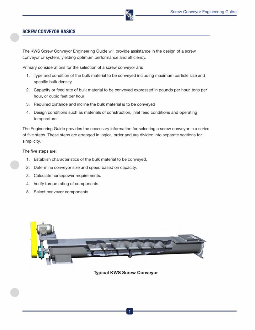
Typical KWS Screw Conveyor
DesignEngineeringManufacturing
2
Screw Conveyor Engineering Guide
TYPes Of sCReW COnVeYORs
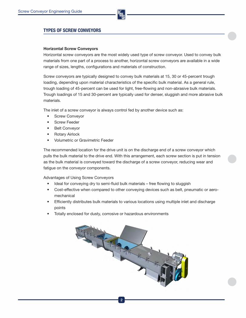
Horizontal Screw Conveyors
Horizontal screw conveyors are the most widely used type of screw conveyor . Used to convey bulk
materials from one part of a process to another, horizontal screw conveyors are available in a wide
range of sizes, lengths, configurations and materials of construction .
Screw conveyors are typically designed to convey bulk materials at 15, 30 or 45-percent trough
loading, depending upon material characteristics of the specific bulk material . as a general rule,
trough loading of 45-percent can be used for light, free-flowing and non-abrasive bulk materials .
Trough loadings of 15 and 30-percent are typically used for denser, sluggish and more abrasive bulk
materials .
The inlet of a screw conveyor is always control fed by another device such as:
• ScrewConveyor
• ScrewFeeder
• BeltConveyor
• RotaryAirlock
• VolumetricorGravimetricFeeder
The recommended location for the drive unit is on the discharge end of a screw conveyor which
pulls the bulk material to the drive end . with this arrangement, each screw section is put in tension
as the bulk material is conveyed toward the discharge of a screw conveyor, reducing wear and
fatigue on the conveyor components .
advantages of Using Screw Conveyors
• Idealforconveyingdrytosemi-fluidbulkmaterials–freeflowingtosluggish
• Cost-effectivewhencomparedtootherconveyingdevicessuchasbelt,pneumaticoraero-
mechanical
• Efficientlydistributesbulkmaterialstovariouslocationsusingmultipleinletanddischarge
points
• Totallyenclosedfordusty,corrosiveorhazardousenvironments
3
DesignEngineeringManufacturing
Screw Conveyor Engineering Guide
TYPes Of sCReW COnVeYORs
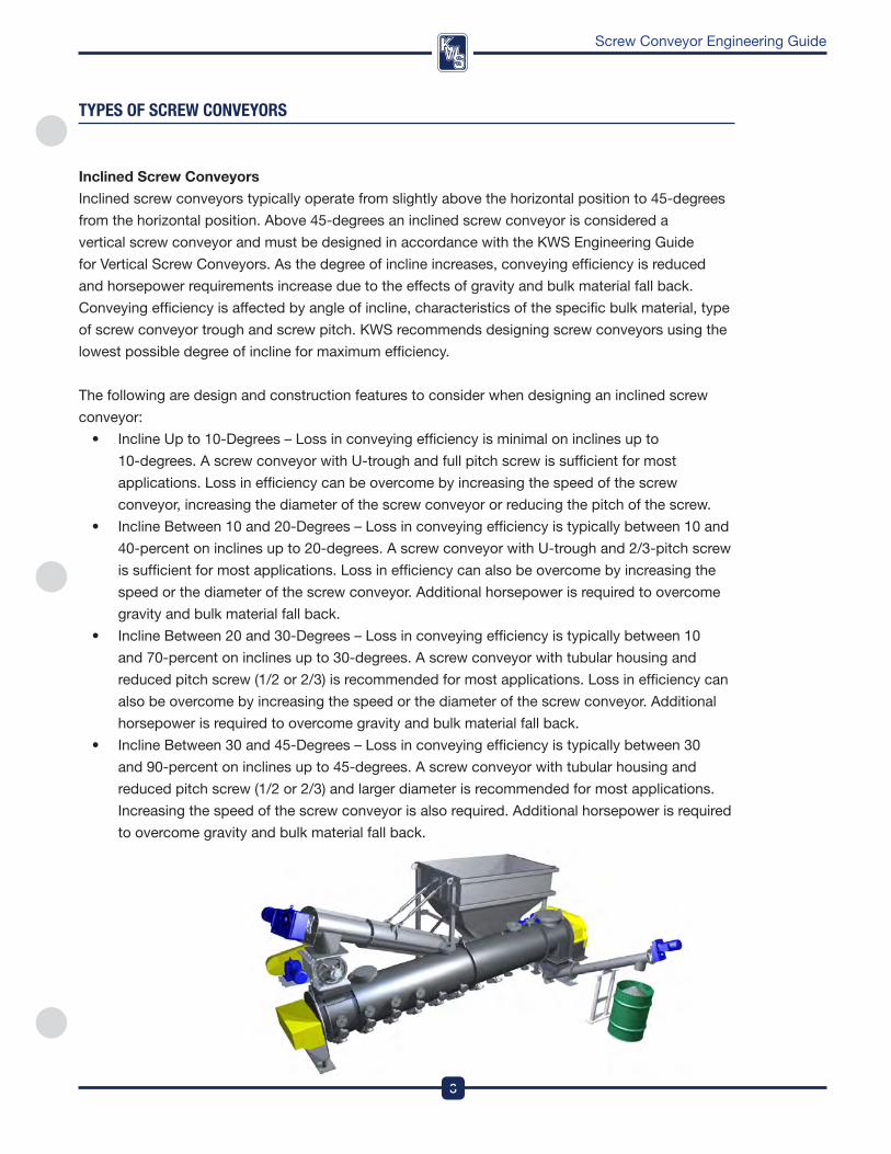
Inclined Screw Conveyors
inclined screw conveyors typically operate from slightly above the horizontal position to 45-degrees
from the horizontal position . above 45-degrees an inclined screw conveyor is considered a
vertical screw conveyor and must be designed in accordance with the kwS Engineering Guide
for vertical Screw Conveyors . as the degree of incline increases, conveying efficiency is reduced
and horsepower requirements increase due to the effects of gravity and bulk material fall back .
Conveying efficiency is affected by angle of incline, characteristics of the specific bulk material, type
of screw conveyor trough and screw pitch . kwS recommends designing screw conveyors using the
lowest possible degree of incline for maximum efficiency .
The following are design and construction features to consider when designing an inclined screw
conveyor:
• InclineUpto10-Degrees–Lossinconveyingefficiencyisminimaloninclinesupto
10-degrees . a screw conveyor with U-trough and full pitch screw is sufficient for most
applications . Loss in efficiency can be overcome by increasing the speed of the screw
conveyor, increasing the diameter of the screw conveyor or reducing the pitch of the screw .
• InclineBetween10and20-Degrees–Lossinconveyingefficiencyistypicallybetween10and
40-percent on inclines up to 20-degrees . a screw conveyor with U-trough and 2/3-pitch screw
is sufficient for most applications . Loss in efficiency can also be overcome by increasing the
speed or the diameter of the screw conveyor . additional horsepower is required to overcome
gravity and bulk material fall back .
• InclineBetween20and30-Degrees–Lossinconveyingefficiencyistypicallybetween10
and 70-percent on inclines up to 30-degrees . a screw conveyor with tubular housing and
reduced pitch screw (1/2 or 2/3) is recommended for most applications . Loss in efficiency can
also be overcome by increasing the speed or the diameter of the screw conveyor . additional
horsepower is required to overcome gravity and bulk material fall back .
• InclineBetween30and45-Degrees–Lossinconveyingefficiencyistypicallybetween30
and 90-percent on inclines up to 45-degrees . a screw conveyor with tubular housing and
reduced pitch screw (1/2 or 2/3) and larger diameter is recommended for most applications .
increasing the speed of the screw conveyor is also required . additional horsepower is required
to overcome gravity and bulk material fall back .
DesignEngineeringManufacturing
4
Screw Conveyor Engineering Guide
TYPes Of sCReW COnVeYORs
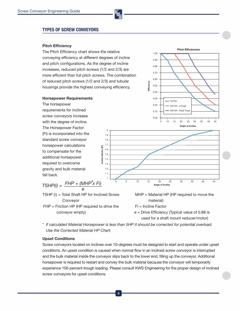
pitch Efficiency
The pitch Efficiency chart shows the relative
conveying efficiency at different degrees of incline
and pitch configurations . as the degree of incline
increases, reduced pitch screws (1/2 and 2/3) are
more efficient than full pitch screws . The combination
of reduced pitch screws (1/2 and 2/3) and tubular
housings provide the highest conveying efficiency .
Horsepower Requirements
The horsepower
requirements for inclined
screw conveyors increase
with the degree of incline .
The Horsepower factor
(fi) is incorporated into the
standard screw conveyor
horsepower calculations
to compensate for the
additional horsepower
required to overcome
gravity and bulk material
fall back .
2
1.9
1.8
1.7
1.6
1.5
1.4
1.3
1.2
1.1
10 5 10 15 20 25 30 35 40 45
Angle of Incline
Incl
ine
afac
tor (
Fi)
1.00
0.90
0.80
0.70
0.60
0.50
0.40
0.30
0.20
0.10
0.000 10 15 20 25 30 35 40 45
Angle of Incline
Pitch Efficiencies
Effic
ienc
y
Full Pitch
Half Pitch – U-Trough
Half Pitch – Tubular Trough
* If calculated Material Horsepower is less than 5HP it should be corrected for potential overload.
Use the Corrected Material HP Chart.
Upset Conditions
Screw conveyors located on inclines over 10-degrees must be designed to start and operate under upset
conditions . an upset condition is caused when normal flow in an inclined screw conveyor is interrupted
and the bulk material inside the conveyor slips back to the lower end, filling up the conveyor . additional
horsepower is required to restart and convey the bulk material because the conveyor will temporarily
experience 100-percent trough loading . please consult kwS Engineering for the proper design of inclined
screw conveyors for upset conditions .
TSHp (i) = Total Shaft Hp for inclined Screw
Conveyor
fHp = friction Hp (Hp required to drive the
conveyor empty)
MHp = Material Hp (Hp required to move the
material)
fi = incline factor
e = drive Efficiency (Typical value of 0 .88 is
used for a shaft mount reducer/motor)
5
DesignEngineeringManufacturing
Screw Conveyor Engineering Guide
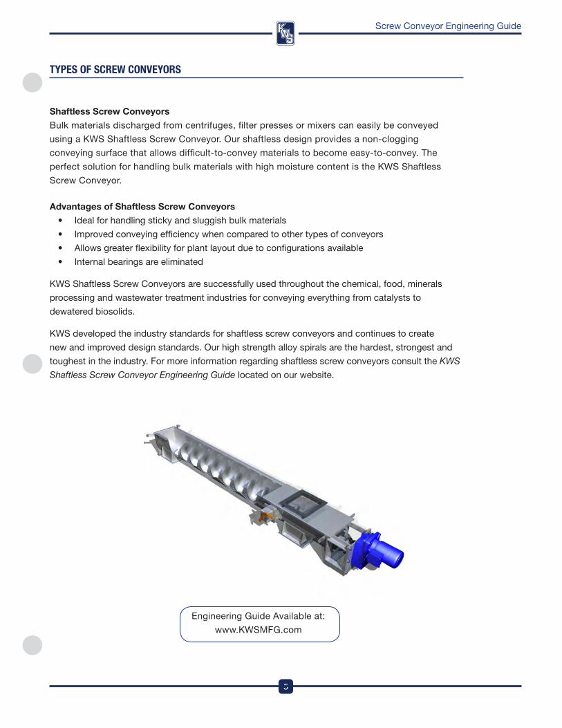
Shaftless Screw Conveyors
Bulk materials discharged from centrifuges, filter presses or mixers can easily be conveyed
using a kwS Shaftless Screw Conveyor . our shaftless design provides a non-clogging
conveying surface that allows difficult-to-convey materials to become easy-to-convey . The
perfect solution for handling bulk materials with high moisture content is the kwS Shaftless
Screw Conveyor .
Advantages of Shaftless Screw Conveyors
• Idealforhandlingstickyandsluggishbulkmaterials
• Improvedconveyingefficiencywhencomparedtoothertypesofconveyors
• Allowsgreaterflexibilityforplantlayoutduetoconfigurationsavailable
• Internalbearingsareeliminated
kwS Shaftless Screw Conveyors are successfully used throughout the chemical, food, minerals
processing and wastewater treatment industries for conveying everything from catalysts to
dewatered biosolids .
kwS developed the industry standards for shaftless screw conveyors and continues to create
new and improved design standards . our high strength alloy spirals are the hardest, strongest and
toughest in the industry . for more information regarding shaftless screw conveyors consult the KWS
Shaftless Screw Conveyor Engineering Guide located on our website .
TYPes Of sCReW COnVeYORs
Engineering Guide available at:
www .kwSMfG .com
DesignEngineeringManufacturing
6
Screw Conveyor Engineering Guide
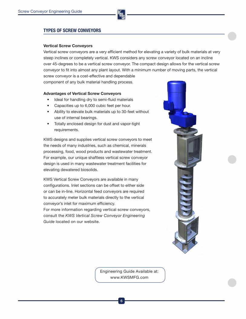
Vertical Screw Conveyors
vertical screw conveyors are a very efficient method for elevating a variety of bulk materials at very
steep inclines or completely vertical . kwS considers any screw conveyor located on an incline
over 45-degrees to be a vertical screw conveyor . The compact design allows for the vertical screw
conveyor to fit into almost any plant layout . with a minimum number of moving parts, the vertical
screw conveyor is a cost-effective and dependable
component of any bulk material handling process .
Advantages of Vertical Screw Conveyors
• Idealforhandlingdrytosemi-fluidmaterials
• Capacitiesupto6,000cubicfeetperhour.
• Abilitytoelevatebulkmaterialsupto30-feetwithout
use of internal bearings .
• Totallyencloseddesignfordustandvapor-tight
requirements .
kwS designs and supplies vertical screw conveyors to meet
the needs of many industries, such as chemical, minerals
processing, food, wood products and wastewater treatment .
for example, our unique shaftless vertical screw conveyor
design is used in many wastewater treatment facilities for
elevating dewatered biosolids .
kwS vertical Screw Conveyors are available in many
configurations . inlet sections can be offset to either side
or can be in-line . Horizontal feed conveyors are required
to accurately meter bulk materials directly to the vertical
conveyor’s inlet for maximum efficiency .
for more information regarding vertical screw conveyors,
consult the KWS Vertical Screw Conveyor Engineering
Guide located on our website .
TYPes Of sCReW COnVeYORs
Engineering Guide available at:
www .kwSMfG .com
7
DesignEngineeringManufacturing
Screw Conveyor Engineering Guide
TYPes Of sCReW feeDeRs
Screw feeders
Screw feeders are designed to meter bulk materials and are typically located at the beginning of
a process . Capacity or feed rate can be accurately controlled with screw feeders . variable speed
drives improve metering accuracy and can provide a wide range of feed rates . Screw feeders are
available in a variety of sizes, lengths, configurations and materials of construction .
The inlet of a screw feeder is always flood loaded (100-percent) . a screw feeder is typically mounted
directly to a:
• Hopper–Squareorrectangularinshapewithslopedbottomandlimitedstoragecapacity
• Bin–Squareorrectangularinshapewithslopedbottomandlargestoragecapacity
• Silo–Cylindricalinshapewithconeormass-flowbottomandlargestoragecapacity
Several factors must be considered when designing a screw feeder, including:
1 . flow characteristics of bulk material being stored and metered
2 . density of bulk material in both stored and metered condition
3 . Maximum and minimum capacity or feed rate of process
4 . Bulk material size with screen analysis
5 . width and length of screw feeder inlet opening
6 . overall length of screw feeder
7 . Height of bulk material in hopper, bin or silo
with the screw feeder inlet flood loaded (100-percent), the design of the screw in the inlet area and
the screw speed determine the desired capacity or feed rate .
Most screw feeders are less than 20-feet in length because the use of internal hanger bearings is
not recommended . in most applications a short screw feeder will meter a bulk material to a screw
conveyor for transfer to the next step of the process .
kwS designs and manufactures three types of screw feeders:
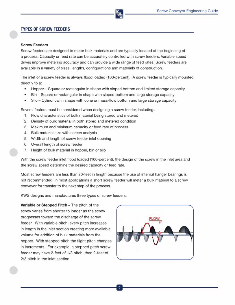
Variable or Stepped pitch – The pitch of the
screw varies from shorter to longer as the screw
progresses toward the discharge of the screw
feeder . with variable pitch, every pitch increases
in length in the inlet section creating more available
volume for addition of bulk materials from the
hopper . with stepped pitch the flight pitch changes
in increments . for example, a stepped pitch screw
feeder may have 2-feet of 1/3 pitch, then 2-feet of
2/3 pitch in the inlet section .
DesignEngineeringManufacturing
8
Screw Conveyor Engineering Guide
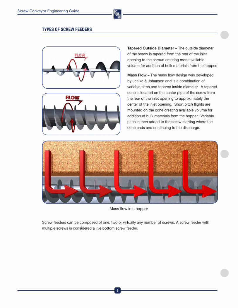
Tapered outside Diameter – The outside diameter
of the screw is tapered from the rear of the inlet
opening to the shroud creating more available
volume for addition of bulk materials from the hopper .
Mass flow – The mass flow design was developed
by Jenike & Johanson and is a combination of
variable pitch and tapered inside diameter . a tapered
cone is located on the center pipe of the screw from
the rear of the inlet opening to approximately the
center of the inlet opening . Short pitch flights are
mounted on the cone creating available volume for
addition of bulk materials from the hopper . variable
pitch is then added to the screw starting where the
cone ends and continuing to the discharge .
TYPes Of sCReW feeDeRs
Mass flow in a hopper
Screw feeders can be composed of one, two or virtually any number of screws . a screw feeder with
multiple screws is considered a live bottom screw feeder .
9
DesignEngineeringManufacturing
Screw Conveyor Engineering Guide
1
2
3
4
5
6
7
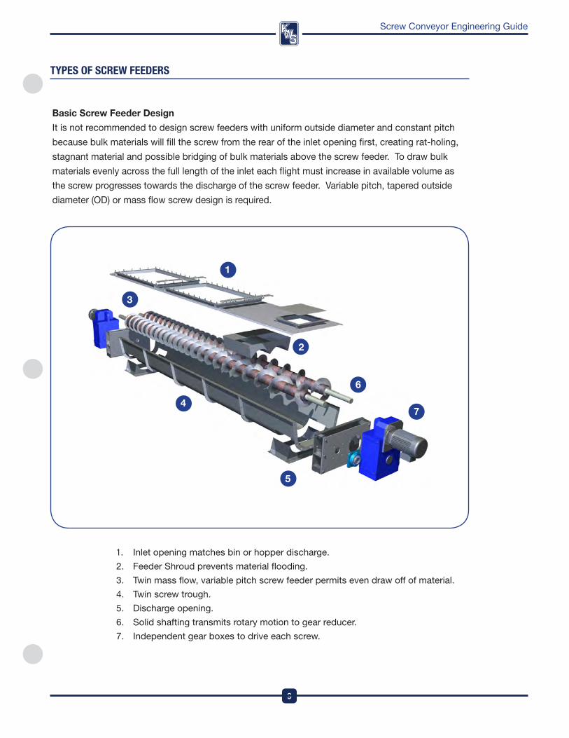
1 . inlet opening matches bin or hopper discharge .
2 . feeder Shroud prevents material flooding .
3 . Twin mass flow, variable pitch screw feeder permits even draw off of material .
4 . Twin screw trough .
5 . discharge opening .
6 . Solid shafting transmits rotary motion to gear reducer .
7 . independent gear boxes to drive each screw .
TYPes Of sCReW feeDeRs
Basic Screw feeder Design
it is not recommended to design screw feeders with uniform outside diameter and constant pitch
because bulk materials will fill the screw from the rear of the inlet opening first, creating rat-holing,
stagnant material and possible bridging of bulk materials above the screw feeder . To draw bulk
materials evenly across the full length of the inlet each flight must increase in available volume as
the screw progresses towards the discharge of the screw feeder . variable pitch, tapered outside
diameter (od) or mass flow screw design is required .
DesignEngineeringManufacturing
10
Screw Conveyor Engineering Guide
feeder Shroud
Screw feeders must be equipped with a shroud for at least 2 pitches beyond the inlet opening to
prevent flooding of the bulk material past the inlet . The shroud is a curved cover that converts a
standard U-trough into a tubular housing to prevent bulk materials from flooding past the screw .
Extended shrouds, tubular housings or short pitch flights can be utilized for accurate feed rate
control when metering very free flowing bulk materials .
Screw feeder Capacity and Speed
The pitch of the last screw flight going into the shroud determines the feed rate of the screw feeder
and is called the Control pitch . The Control pitch is typically less than full pitch . The capacity of the
Control pitch is calculated in cubic feet per hour per rpM . The speed of the screw feeder can be determined by dividing the maximum screw feeder capacity in cubic feet per hour by the capacity of
the Control pitch in cubic feet per hour per rpM . Most screw feeder speeds are lower than standard
screw conveyor speeds . for example, in heavy industrial applications, screw feeders typically
operate at speeds less than 20-rpM . More torque is generated at lower operating speeds ensuring
the screw feeder does not stall at start-up .
Screw feeder Horsepower Requirements
The horsepower and torque requirements for a screw feeder are much higher than a comparable screw
conveyor . a screw feeder must start up with a flood loaded inlet and the head load weight of the bulk
material in the inlet section . Bulk materials also tend to pack when under pressure in a hopper, bin
or silo . as the bulk material density increases, so do the horsepower and torque requirements . The
Material factor or Hp factor (Mf) can exceed 4 .0 for some bulk materials when under pressure and
packed . The start-up horsepower and torque can easily be 2 .5 times the normal operating conditions .
please consult the kwS Engineering department for proper screw feeder design .
TYPes Of sCReW feeDeRs
11
DesignEngineeringManufacturing
Screw Conveyor Engineering Guide
oTHER TYpES of SCREW fEEDERS
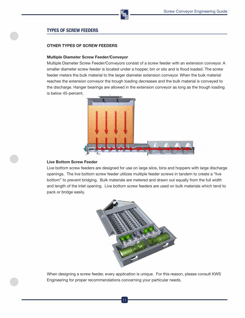
Multiple Diameter Screw feeder/Conveyor
Multiple diameter Screw feeder/Conveyors consist of a screw feeder with an extension conveyor . a
smaller diameter screw feeder is located under a hopper, bin or silo and is flood loaded . The screw
feeder meters the bulk material to the larger diameter extension conveyor . when the bulk material
reaches the extension conveyor the trough loading decreases and the bulk material is conveyed to
the discharge . Hanger bearings are allowed in the extension conveyor as long as the trough loading
is below 45-percent .
live Bottom Screw feeder
Live bottom screw feeders are designed for use on large silos, bins and hoppers with large discharge
openings . The live bottom screw feeder utilizes multiple feeder screws in tandem to create a “live
bottom” to prevent bridging . Bulk materials are metered and drawn out equally from the full width
and length of the inlet opening . Live bottom screw feeders are used on bulk materials which tend to
pack or bridge easily .
when designing a screw feeder, every application is unique . for this reason, please consult kwS
Engineering for proper recommendations concerning your particular needs .
TYPes Of sCReW feeDeRs
DesignEngineeringManufacturing
12
Screw Conveyor Engineering Guide
TYPes Of sCReW feeDeRs
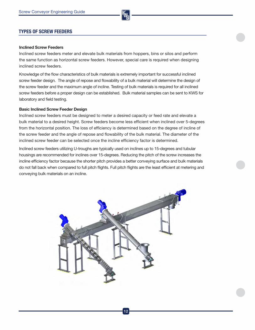
Inclined Screw feeders
inclined screw feeders meter and elevate bulk materials from hoppers, bins or silos and perform
the same function as horizontal screw feeders . However, special care is required when designing
inclined screw feeders .
knowledge of the flow characteristics of bulk materials is extremely important for successful inclined
screw feeder design . The angle of repose and flowability of a bulk material will determine the design of
the screw feeder and the maximum angle of incline . Testing of bulk materials is required for all inclined
screw feeders before a proper design can be established . Bulk material samples can be sent to kwS for
laboratory and field testing .
Basic Inclined Screw feeder Design
inclined screw feeders must be designed to meter a desired capacity or feed rate and elevate a
bulk material to a desired height . Screw feeders become less efficient when inclined over 5-degrees
from the horizontal position . The loss of efficiency is determined based on the degree of incline of
the screw feeder and the angle of repose and flowability of the bulk material . The diameter of the
inclined screw feeder can be selected once the incline efficiency factor is determined .
inclined screw feeders utilizing U-troughs are typically used on inclines up to 15-degrees and tubular
housings are recommended for inclines over 15-degrees . reducing the pitch of the screw increases the
incline efficiency factor because the shorter pitch provides a better conveying surface and bulk materials
do not fall back when compared to full pitch flights . full pitch flights are the least efficient at metering and
conveying bulk materials on an incline .
13
DesignEngineeringManufacturing
Screw Conveyor Engineering Guide
Inclined Screw feeder Capacity and Speed
inclined screw feeders typically operate at higher speeds when compared to horizontal screw
feeders because additional speed is required to elevate a bulk material and overcome the forces of
gravity and bulk material fall back . The desired capacity is adjusted using the incline efficiency factor
calculated from testing of the bulk material . The speed of the inclined screw feeder can then be
determined .
Inclined Screw feeder Horsepower Requirements
inclined screw feeders require more horsepower and torque when compared to a horizontal screw
feeder . additional horsepower and torque is required to elevate a bulk material and overcome the
forces of gravity and bulk material fall back . Bulk materials can become packed inside an inclined
screw feeder, causing more demand on the drive unit .
Inlet length
The inlet length on an inclined screw feeder must be kept to a minimum to prevent the bulk material
from falling back over the top of the flights in the inlet section . Typically, the length of the inlet should
not exceed 2 times the diameter of the screw for an inclined screw feeder .
flight pitch Changes
inclined screw feeders are typically designed with multiple flight pitch changes . Shorter flight pitches
are used in the inlet section to control the capacity or feed rate . Typically, the flight pitch increases
beyond the inlet to reduce the trough loading to less than 100-percent . The conveying efficiency
must be calculated in the longer flight pitch section to make sure the desired capacity or feed rate
is met . improper design of the flight pitches could result in the inclined screw feeder becoming
plugged at the transition from shorter to longer pitch flights .
inclined screw feeders can be a very important part of your process . please consult kwS
Engineering for proper inclined screw feeder design .
TYPes Of sCReW feeDeRs
DesignEngineeringManufacturing
14
Screw Conveyor Engineering Guide
bUlK MaTeRIal CHaRaCTeRIsTICs
Conveyor size, speed and horsepower requirements are directly affected by the following
characteristics of the conveyed bulk material. More specific information will be discussed in the
ensuing pages clarifying several of the factors listed in the Bulk Material Table.
Maximum particle Size and Bulk Material lump Size
particle size is measured in inches or by a mesh screen gauge . other material size designations such
as irregular, shredded, or % oil have special considerations in the design process . in addition to particle
size, lump size is also an important consideration and will be discussed in detail in the next few pages .
Bulk Density
Conveying capacity for screw conveyors and screw feeders is calculated volumetrically in cubic feet
per hour (ft3/hr) . The bulk density of the bulk material is needed in order to convert capacities given
in tons per hour or pounds per hour to cubic feet per hour .
The bulk density column of the Bulk Material Table provides an average bulk density or a range of
bulk densities for each bulk material . accurate bulk density information is needed for selecting the
proper screw conveyor or screw feeder .
% Trough loading
Trough loading is a prime factor in determining conveyor size and is based on the maximum depth at
which bulk materials will flow through a screw conveyor without causing undue wear on the conveyor
components, such as screws, hanger bearings, couplings shafts and troughs . The recommended
trough loading is lower for abrasive bulk materials in comparison to non-abrasive bulk materials .
Material factor (Mf)
Material factor represents the resistance of a bulk material to be conveyed and is used for
calculating screw conveyor horsepower . The material factor may vary for screw feeders . please
consult kwS Engineering for screw feeder applications .
Component / Bearing Series
The recommended component series assists in the selection of screw conveyor components for
a given bulk material . in general, lighter duty construction is acceptable for free flowing and non-
abrasive bulk materials . Heavier duty construction is recommended for sluggish and abrasive bulk
materials . The alphabetical code refers to the general component series and the numerical code
refers to hanger bearing recommendations .
Abrasiveness, Corrosiveness, flowability, and Special Characteristics
Each of these characteristics affect how the material reacts to and moves through the conveyor .
The characteristics explanations and the Bulk Material Table on the following pages contain important
information for the proper design of screw conveyors and screw feeders. Please contact KWS
Engineering for materials not listed in the Bulk Material Table.
15
DesignEngineeringManufacturing
Screw Conveyor Engineering Guide
bUlK MaTeRIal CHaRaCTeRIsTICs
Bulk Material lump Size
Bulk material lump size must be considered when designing a screw conveyor . Screw conveyor
diameter not only depends on the capacity of the bulk material to be conveyed, but also the size and
proportion of lumps in the bulk material . Lump size is determined by the maximum dimension of the
largest lumps . if a lump has one dimension much longer than its transverse cross-section, then the
longer dimension will be used to determine the lump size .
The character of the lump must also be considered when designing a screw conveyor . Some bulk
materials have hard lumps that won’t break up when conveyed by a screw conveyor . other bulk
materials may have lumps that are fairly hard but degrade when conveyed causing a reduction in
the lump size . Bulk materials that have lumps that are easily broken up when conveyed have no
limitations on conveyor size .
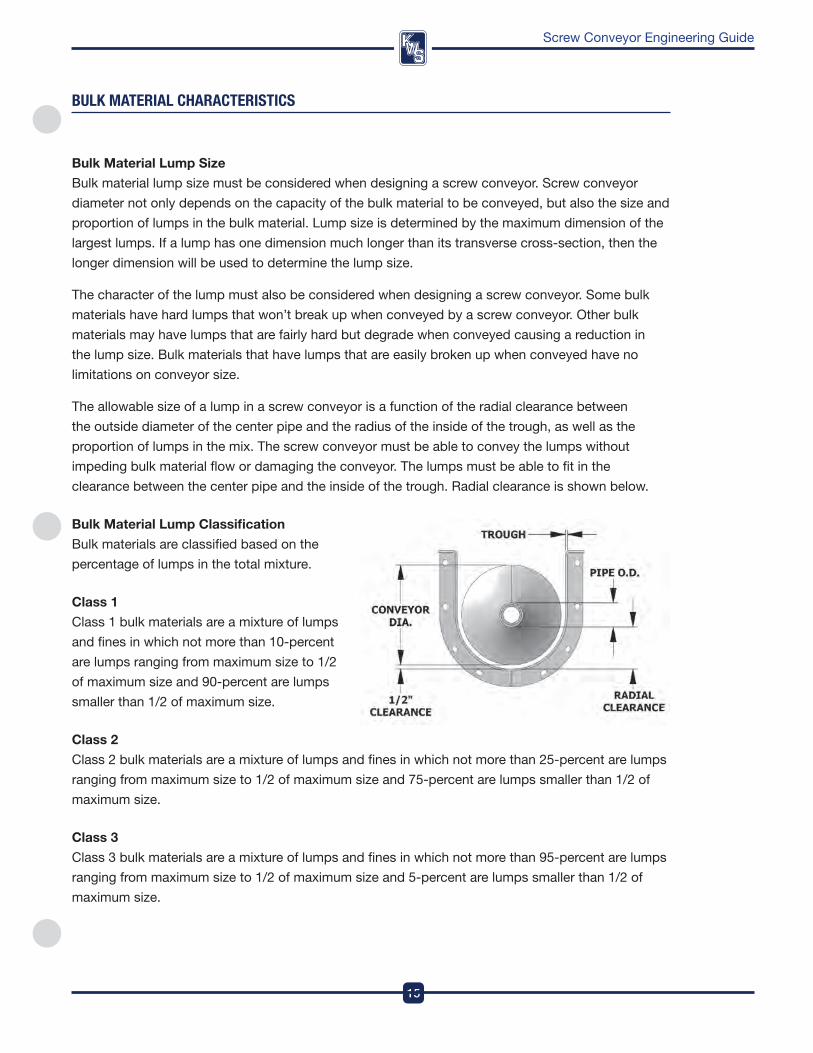
The allowable size of a lump in a screw conveyor is a function of the radial clearance between
the outside diameter of the center pipe and the radius of the inside of the trough, as well as the
proportion of lumps in the mix . The screw conveyor must be able to convey the lumps without
impeding bulk material flow or damaging the conveyor . The lumps must be able to fit in the
clearance between the center pipe and the inside of the trough . radial clearance is shown below .
Bulk Material lump Classification
Bulk materials are classified based on the
percentage of lumps in the total mixture .
Class 1
Class 1 bulk materials are a mixture of lumps
and fines in which not more than 10-percent
are lumps ranging from maximum size to 1/2
of maximum size and 90-percent are lumps
smaller than 1/2 of maximum size .
Class 2
Class 2 bulk materials are a mixture of lumps and fines in which not more than 25-percent are lumps
ranging from maximum size to 1/2 of maximum size and 75-percent are lumps smaller than 1/2 of
maximum size .
Class 3
Class 3 bulk materials are a mixture of lumps and fines in which not more than 95-percent are lumps
ranging from maximum size to 1/2 of maximum size and 5-percent are lumps smaller than 1/2 of
maximum size .
DesignEngineeringManufacturing
16
Screw Conveyor Engineering Guide
bUlK MaTeRIal CHaRaCTeRIsTICs
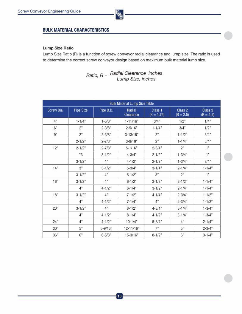
Bulk Material Lump Size Table
Screw Dia. Pipe Size Pipe O.D. Radial Clearance
Class 1 (R = 1.75)
Class 2 (R = 2.5)
Class 3 (R = 4.5)
4” 1-1/4” 1-5/8” 1-11/16” 3/4” 1/2” 1/4”
6” 2” 2-3/8” 2-5/16” 1-1/4” 3/4” 1/2”
9” 2” 2-3/8” 3-13/16” 2” 1-1/2” 3/4”
2-1/2” 2-7/8” 3-9/19” 2” 1-1/4” 3/4”
12” 2-1/2” 2-7/8” 5-1/16” 2-3/4” 2” 1”
”3 3-1/2” 4-3/4” 2-1/2” 1-3/4” 1”
3-1/2” 4” 4-1/2” 2-1/2” 1-3/4” 3/4”
14” 3” 3-1/2” 5-3/4” 3-1/4” 2-1/4” 1-1/4”
3-1/2” 4” 5-1/2” 3” 2” 1”
16” 3-1/2” 4” 6-1/2” 3-1/2” 2-1/2” 1-1/4”
4” 4-1/2” 6-1/4” 3-1/2” 2-1/4” 1-1/4”
18” 3-1/2” 4” 7-1/2” 4-1/4” 2-3/4” 1-1/2”
4” 4-1/2” 7-1/4” 4” 2-3/4” 1-1/2”
20” 3-1/2” 4” 8-1/2” 4-3/4” 3-1/4” 1-3/4”
4” 4-1/2” 8-1/4” 4-1/2” 3-1/4” 1-3/4”
24” 4” 4-1/2” 10-1/4” 5-3/4” 4” 2-1/4”
30” 5” 5-9/16” 12-11/16” 7” 5” 2-3/4”
36” 6” 6-5/8” 15-3/16” 8-1/2” 6” 3-1/4”
lump Size Ratio
Lump Size ratio (r) is a function of screw conveyor radial clearance and lump size . The ratio is used
to determine the correct screw conveyor design based on maximum bulk material lump size .
17
DesignEngineeringManufacturing
Screw Conveyor Engineering Guide
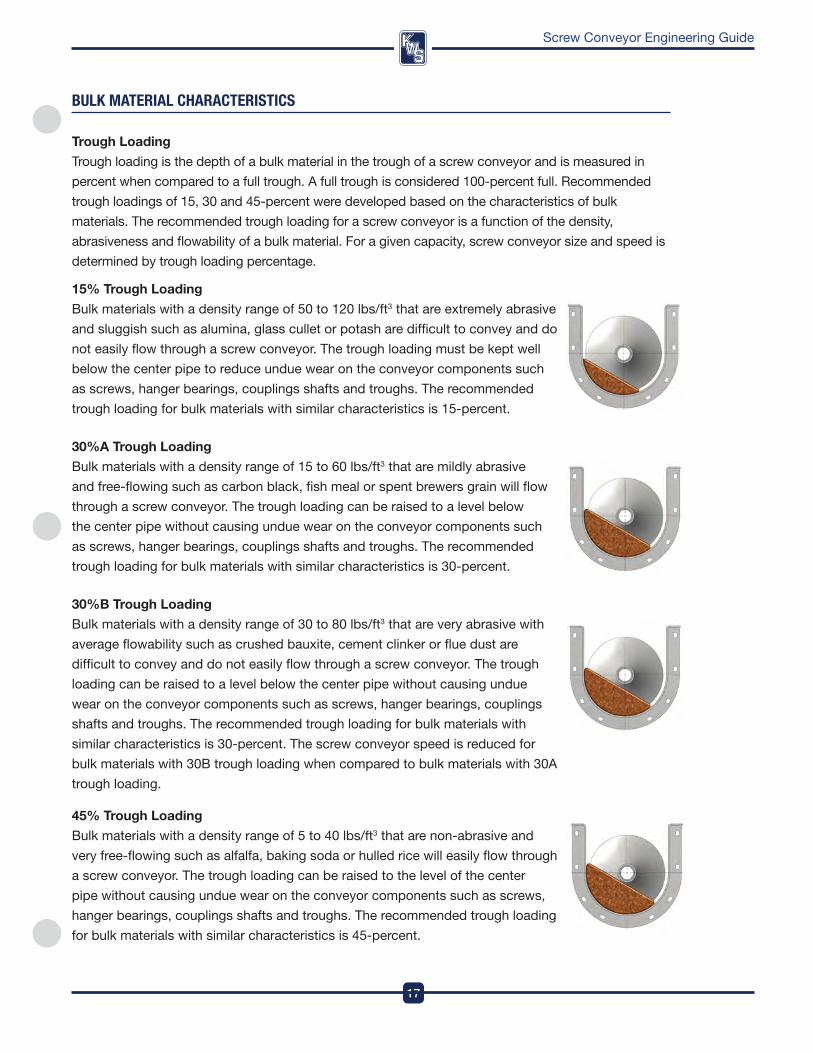
Trough loading
Trough loading is the depth of a bulk material in the trough of a screw conveyor and is measured in
percent when compared to a full trough . a full trough is considered 100-percent full . recommended
trough loadings of 15, 30 and 45-percent were developed based on the characteristics of bulk
materials . The recommended trough loading for a screw conveyor is a function of the density,
abrasiveness and flowability of a bulk material . for a given capacity, screw conveyor size and speed is
determined by trough loading percentage .
bUlK MaTeRIal CHaRaCTeRIsTICs
15% Trough loading
Bulk materials with a density range of 50 to 120 lbs/ft3 that are extremely abrasive
and sluggish such as alumina, glass cullet or potash are difficult to convey and do
not easily flow through a screw conveyor . The trough loading must be kept well
below the center pipe to reduce undue wear on the conveyor components such
as screws, hanger bearings, couplings shafts and troughs . The recommended
trough loading for bulk materials with similar characteristics is 15-percent .
30%A Trough loading
Bulk materials with a density range of 15 to 60 lbs/ft3 that are mildly abrasive
and free-flowing such as carbon black, fish meal or spent brewers grain will flow
through a screw conveyor . The trough loading can be raised to a level below
the center pipe without causing undue wear on the conveyor components such
as screws, hanger bearings, couplings shafts and troughs . The recommended
trough loading for bulk materials with similar characteristics is 30-percent .
30%B Trough loading
Bulk materials with a density range of 30 to 80 lbs/ft3 that are very abrasive with
average flowability such as crushed bauxite, cement clinker or flue dust are
difficult to convey and do not easily flow through a screw conveyor . The trough
loading can be raised to a level below the center pipe without causing undue
wear on the conveyor components such as screws, hanger bearings, couplings
shafts and troughs . The recommended trough loading for bulk materials with
similar characteristics is 30-percent . The screw conveyor speed is reduced for
bulk materials with 30B trough loading when compared to bulk materials with 30a
trough loading .
45% Trough loading
Bulk materials with a density range of 5 to 40 lbs/ft3 that are non-abrasive and
very free-flowing such as alfalfa, baking soda or hulled rice will easily flow through
a screw conveyor . The trough loading can be raised to the level of the center
pipe without causing undue wear on the conveyor components such as screws,
hanger bearings, couplings shafts and troughs . The recommended trough loading
for bulk materials with similar characteristics is 45-percent .
DesignEngineeringManufacturing
18
Screw Conveyor Engineering Guide
COMPOnenT/beaRInG seRIes
CoMpoNENT SERIES
The recommended component series for bulk materials are listed in the Bulk Material Table . The
alphabetical series codes refer to the minimum construction requirements for a screw conveyor used
to convey a specific bulk material . Series a and B construction can be used for most light, non-
abrasive and free-flowing bulk materials . Series C and d construction are recommended for dense,
abrasive and sluggish bulk materials . please consult kwS Engineering for further assistance .
Series A
Light duty Construction – Series a bulk materials such as barley, cocoa beans, fish meal and sawdust
are light, non-abrasive and very free-flowing . Light duty construction is very cost-effective and consists
of the thinnest gauge materials available for screws, troughs and covers . Helicoid screws and angle
flange troughs are recommended for Series a bulk materials .
Series B
Medium duty Construction – Series B bulk materials such as alfalfa pellets, dry bagasse, activated
carbon and crushed ice are slightly higher in bulk density, have some abrasiveness and are slightly less
free-flowing when compared to Series a bulk materials . Medium duty construction is cost-effective
and consists of slightly heavier gauge materials for screws, troughs and covers . Helicoid screws and
angle flange troughs are recommended for Series B bulk materials .
Series C
Heavy duty Construction – Series C bulk materials such as alumina fines, spent distiller’s grain,
foundry sand and sodium sulphate are dense, abrasive and sluggish when compared to Series a and
B bulk materials . Heavy duty construction is required to prevent excessive maintenance or downtime
and consists of heavy duty screws, troughs and covers . Sectional screws and formed flange troughs
are recommended for Series C bulk materials .
Series D
Extra Heavy duty Construction – Series d bulk materials such as adipic acid, blast furnace slag,
cement clinker and lignite coal are very dense, extremely abrasive and very sluggish when compared
to Series a, B or C bulk materials . Extra heavy duty construction is required to prevent excessive
maintenance or downtime and consists of extra heavy duty screws, troughs and covers . Sectional
screws with weld-on hardsurfacing and formed flange troughs are recommended for Series d bulk
materials .
19
DesignEngineeringManufacturing
Screw Conveyor Engineering Guide
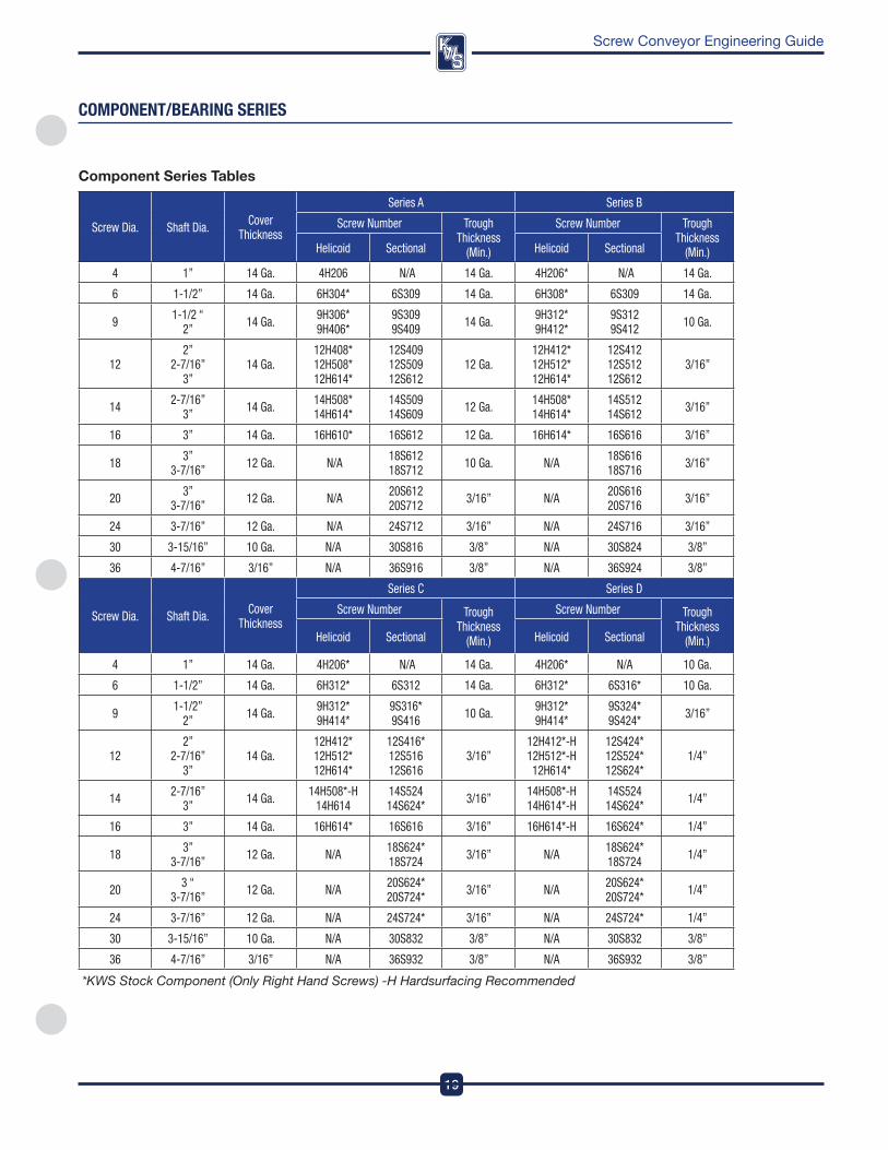
Screw Dia. Shaft Dia. Cover Thickness
Series A Series B
Screw Number Trough Thickness
(Min.)
Screw Number Trough Thickness
(Min.)Helicoid Sectional Helicoid Sectional
4 1” 14 Ga. 4H206 N/A 14 Ga. 4H206* N/A 14 Ga.
6 1-1/2” 14 Ga. 6H304* 6S309 14 Ga. 6H308* 6S309 14 Ga.
9 1-1/2 “ 2” 14 Ga. 9H306*
9H406*9S309 9S409 14 Ga. 9H312*
9H412*9S312 9S412 10 Ga.
122”
2-7/16” 3”
14 Ga.12H408* 12H508* 12H614*
12S409 12S509 12S612
12 Ga.12H412* 12H512* 12H614*
12S412 12S512 12S612
3/16”
14 2-7/16” 3” 14 Ga. 14H508*
14H614*14S509 14S609 12 Ga. 14H508*
14H614*14S512 14S612 3/16”
16 3” 14 Ga. 16H610* 16S612 12 Ga. 16H614* 16S616 3/16”
18 3” 3-7/16” 12 Ga. N/A 18S612
18S712 10 Ga. N/A 18S616 18S716 3/16”
20 3” 3-7/16” 12 Ga. N/A 20S612
20S712 3/16” N/A 20S616 20S716 3/16”
24 3-7/16” 12 Ga. N/A 24S712 3/16” N/A 24S716 3/16”
30 3-15/16” 10 Ga. N/A 30S816 3/8” N/A 30S824 3/8”
36 4-7/16” 3/16” N/A 36S916 3/8” N/A 36S924 3/8”
Screw Dia. Shaft Dia. Cover Thickness
Series C Series D
Screw Number Trough Thickness
(Min.)
Screw Number Trough Thickness
(Min.)Helicoid Sectional Helicoid Sectional
4 1” 14 Ga. 4H206* N/A 14 Ga. 4H206* N/A 10 Ga.
6 1-1/2” 14 Ga. 6H312* 6S312 14 Ga. 6H312* 6S316* 10 Ga.
9 1-1/2” 2” 14 Ga. 9H312*
9H414*9S316* 9S416 10 Ga. 9H312*
9H414*9S324* 9S424* 3/16”
122”
2-7/16” 3”
14 Ga.12H412* 12H512* 12H614*
12S416* 12S516 12S616
3/16”12H412*-H 12H512*-H 12H614*
12S424* 12S524* 12S624*
1/4”
14 2-7/16” 3” 14 Ga. 14H508*-H
14H61414S524 14S624* 3/16” 14H508*-H
14H614*-H14S524 14S624* 1/4”
16 3” 14 Ga. 16H614* 16S616 3/16” 16H614*-H 16S624* 1/4”
18 3” 3-7/16” 12 Ga. N/A 18S624*
18S724 3/16” N/A 18S624* 18S724 1/4”
20 3 “ 3-7/16” 12 Ga. N/A 20S624*
20S724* 3/16” N/A 20S624* 20S724* 1/4”
24 3-7/16” 12 Ga. N/A 24S724* 3/16” N/A 24S724* 1/4”
30 3-15/16” 10 Ga. N/A 30S832 3/8” N/A 30S832 3/8”
36 4-7/16” 3/16” N/A 36S932 3/8” N/A 36S932 3/8”
*KWS Stock Component (Only Right Hand Screws) -H Hardsurfacing Recommended
COMPOnenT/beaRInG seRIes
Component Series Tables
DesignEngineeringManufacturing
20
Screw Conveyor Engineering Guide
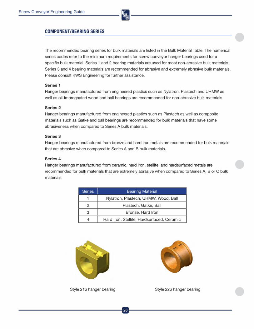
Series Bearing Material
1 nylatron, plastech, UHMw, wood, Ball
2 plastech, Gatke, Ball
3 Bronze, Hard iron
4 Hard iron, Stellite, Hardsurfaced, Ceramic
The recommended bearing series for bulk materials are listed in the Bulk Material Table . The numerical
series codes refer to the minimum requirements for screw conveyor hanger bearings used for a
specific bulk material . Series 1 and 2 bearing materials are used for most non-abrasive bulk materials .
Series 3 and 4 bearing materials are recommended for abrasive and extremely abrasive bulk materials .
please consult kwS Engineering for further assistance .
Series 1
Hanger bearings manufactured from engineered plastics such as nylatron, plastech and UHMw as
well as oil-impregnated wood and ball bearings are recommended for non-abrasive bulk materials .
Series 2
Hanger bearings manufactured from engineered plastics such as plastech as well as composite
materials such as Gatke and ball bearings are recommended for bulk materials that have some
abrasiveness when compared to Series a bulk materials .
Series 3
Hanger bearings manufactured from bronze and hard iron metals are recommended for bulk materials
that are abrasive when compared to Series a and B bulk materials .
Series 4
Hanger bearings manufactured from ceramic, hard iron, stellite, and hardsurfaced metals are
recommended for bulk materials that are extremely abrasive when compared to Series a, B or C bulk
materials .
COMPOnenT/beaRInG seRIes
Style 216 hanger bearing Style 226 hanger bearing

21
DesignEngineeringManufacturing
Screw Conveyor Engineering Guide
Abrasiveness, Corrosiveness and
flowability
The Bulk Material Table also presents
the relative abrasiveness, corrosiveness
and flowability of the bulk materials
listed . These characteristics, as well as
other special aspects of bulk materials,
are given further consideration in the
Component Selection Section . The
nomenclature used in the Bulk Material Table are listed below .
NOTE: Some bulk materials, while they are not corrosive under “normal” conditions, may become
corrosive when heated or in the presence of moisture.
Special Characteristics Notes
notable unusual bulk material
characteristics are listed by alphabetical
codes in the last column of the Bulk
Material Table where applicable . an
explanation of these numerical codes
is shown on the right and in the Bulk
Materials Characteristics section .
faCTORs InflUenCInG sCReW COnVeYOR DesIGn
Description I II III IV
Abrasiveness Mildly Abrasive
Moderately Abrasive
Extremely Abrasive —
Corrosiveness Not Corrosive
Mildly Corrosive
Highly Corrosive —
Flowability
Very Free Flowing
Free Flowing
Average Flowability Sluggish
Angle of ReposeTo 30° 30° - 45° 30° - 45° Beyond 45°
A Builds Up and Hardens
B Generates Static Electricity
C Decomposes—Deteriorates in Storage
D Flammability
E Becomes Plastic or Tends to Soften
F Very Dusty
G Aerates and Becomes Fluid
H Explosiveness
I Stickiness—Adhesion
J Contaminable, Affecting Use
K Degradable, Affecting Use
L Gives Off Harmful or Toxic Gas or Fumes
M Hygroscopic
N Interlocks, Mats, or Agglomerates
O Oils Present
P Packs Under Pressure
Q Very Light and Fluffy—May Be Windswept
R Elevated Temperature
V May Be Conveyed In a Vertical Screw Conveyor
• Consult KWS Engineering Department
DesignEngineeringManufacturing
22
Screw Conveyor Engineering Guide
faCTORs InflUenCInG sCReW COnVeYOR DesIGn
ammonium Sulfate
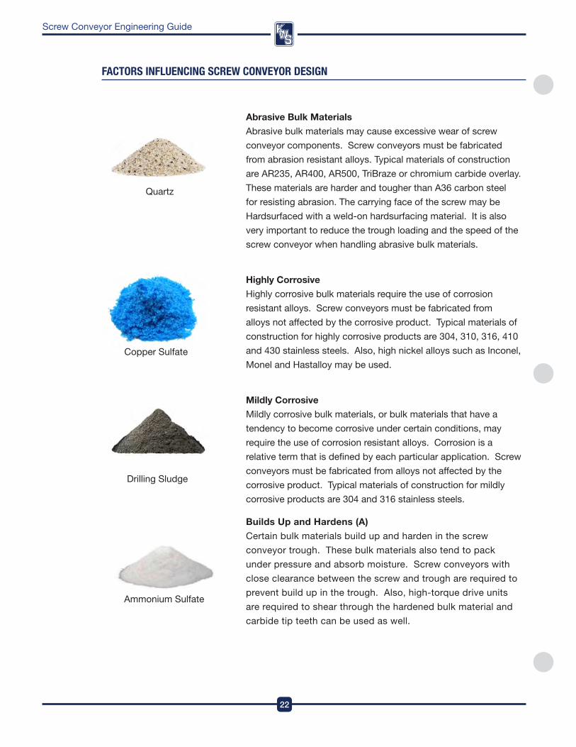
Abrasive Bulk Materials
abrasive bulk materials may cause excessive wear of screw
conveyor components . Screw conveyors must be fabricated
from abrasion resistant alloys . Typical materials of construction
are ar235, ar400, ar500, TriBraze or chromium carbide overlay .
These materials are harder and tougher than a36 carbon steel
for resisting abrasion . The carrying face of the screw may be
Hardsurfaced with a weld-on hardsurfacing material . it is also
very important to reduce the trough loading and the speed of the
screw conveyor when handling abrasive bulk materials .
Highly Corrosive
Highly corrosive bulk materials require the use of corrosion
resistant alloys . Screw conveyors must be fabricated from
alloys not affected by the corrosive product . Typical materials of
construction for highly corrosive products are 304, 310, 316, 410
and 430 stainless steels . also, high nickel alloys such as inconel,
Monel and Hastalloy may be used .
Mildly Corrosive
Mildly corrosive bulk materials, or bulk materials that have a
tendency to become corrosive under certain conditions, may
require the use of corrosion resistant alloys . Corrosion is a
relative term that is defined by each particular application . Screw
conveyors must be fabricated from alloys not affected by the
corrosive product . Typical materials of construction for mildly
corrosive products are 304 and 316 stainless steels .
Builds Up and Hardens (A)
Certain bulk materials build up and harden in the screw
conveyor trough . These bulk materials also tend to pack
under pressure and absorb moisture . Screw conveyors with
close clearance between the screw and trough are required to
prevent build up in the trough . also, high-torque drive units
are required to shear through the hardened bulk material and
carbide tip teeth can be used as well .
Quartz
Copper Sulfate
drilling Sludge
23
DesignEngineeringManufacturing
Screw Conveyor Engineering Guide
Ground Meat
Hay
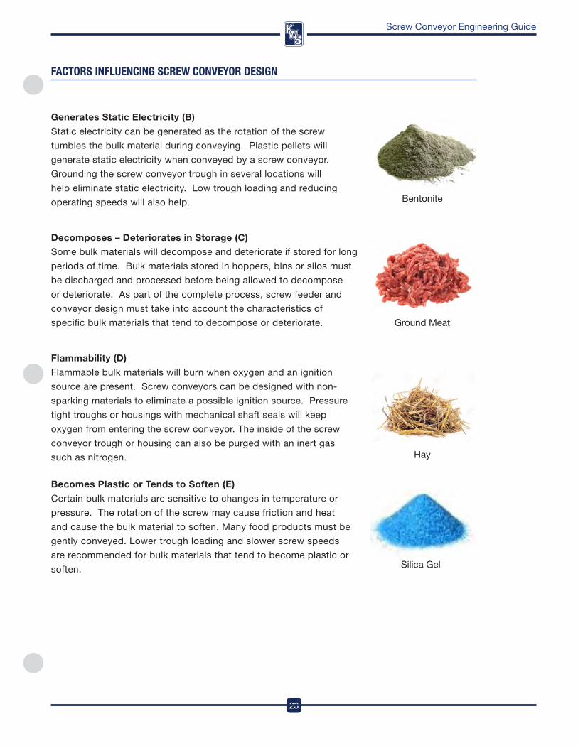
Bentonite
faCTORs InflUenCInG sCReW COnVeYOR DesIGn
Silica Gel
Generates Static Electricity (B)
Static electricity can be generated as the rotation of the screw
tumbles the bulk material during conveying . plastic pellets will
generate static electricity when conveyed by a screw conveyor .
Grounding the screw conveyor trough in several locations will
help eliminate static electricity . Low trough loading and reducing
operating speeds will also help .
Decomposes – Deteriorates in Storage (C)
Some bulk materials will decompose and deteriorate if stored for long
periods of time . Bulk materials stored in hoppers, bins or silos must
be discharged and processed before being allowed to decompose
or deteriorate . as part of the complete process, screw feeder and
conveyor design must take into account the characteristics of
specific bulk materials that tend to decompose or deteriorate .
flammability (D)
flammable bulk materials will burn when oxygen and an ignition
source are present . Screw conveyors can be designed with non-
sparking materials to eliminate a possible ignition source . pressure
tight troughs or housings with mechanical shaft seals will keep
oxygen from entering the screw conveyor . The inside of the screw
conveyor trough or housing can also be purged with an inert gas
such as nitrogen .
Becomes plastic or Tends to Soften (E)
Certain bulk materials are sensitive to changes in temperature or
pressure . The rotation of the screw may cause friction and heat
and cause the bulk material to soften . Many food products must be
gently conveyed . Lower trough loading and slower screw speeds
are recommended for bulk materials that tend to become plastic or
soften .
DesignEngineeringManufacturing
24
Screw Conveyor Engineering Guide
faCTORs InflUenCInG sCReW COnVeYOR DesIGn
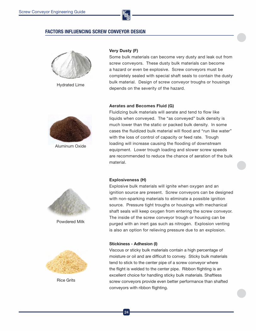
Very Dusty (f)
Some bulk materials can become very dusty and leak out from
screw conveyors . These dusty bulk materials can become
a hazard or even be explosive . Screw conveyors must be
completely sealed with special shaft seals to contain the dusty
bulk material . design of screw conveyor troughs or housings
depends on the severity of the hazard .
Aerates and Becomes fluid (G)
fluidizing bulk materials will aerate and tend to flow like
liquids when conveyed . The “as conveyed” bulk density is
much lower than the static or packed bulk density . in some
cases the fluidized bulk material will flood and “run like water”
with the loss of control of capacity or feed rate . Trough
loading will increase causing the flooding of downstream
equipment . Lower trough loading and slower screw speeds
are recommended to reduce the chance of aeration of the bulk
material .
Explosiveness (H)
Explosive bulk materials will ignite when oxygen and an
ignition source are present . Screw conveyors can be designed
with non-sparking materials to eliminate a possible ignition
source . pressure tight troughs or housings with mechanical
shaft seals will keep oxygen from entering the screw conveyor .
The inside of the screw conveyor trough or housing can be
purged with an inert gas such as nitrogen . Explosion venting
is also an option for relieving pressure due to an explosion .
Stickiness - Adhesion (I)
viscous or sticky bulk materials contain a high percentage of
moisture or oil and are difficult to convey . Sticky bulk materials
tend to stick to the center pipe of a screw conveyor where
the flight is welded to the center pipe . ribbon flighting is an
excellent choice for handling sticky bulk materials . Shaftless
screw conveyors provide even better performance than shafted
conveyors with ribbon flighting .
rice Grits
powdered Milk
aluminum oxide
Hydrated Lime
25
DesignEngineeringManufacturing
Screw Conveyor Engineering Guide
almonds
Galena
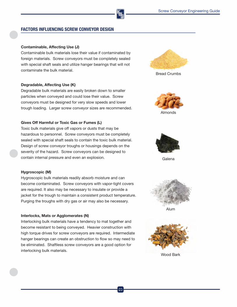
Bread Crumbs
alum
faCTORs InflUenCInG sCReW COnVeYOR DesIGn
Contaminable, Affecting Use (J)
Contaminable bulk materials lose their value if contaminated by
foreign materials . Screw conveyors must be completely sealed
with special shaft seals and utilize hanger bearings that will not
contaminate the bulk material .
Degradable, Affecting Use (K)
degradable bulk materials are easily broken down to smaller
particles when conveyed and could lose their value . Screw
conveyors must be designed for very slow speeds and lower
trough loading . Larger screw conveyor sizes are recommended .
Gives off Harmful or Toxic Gas or fumes (l)
Toxic bulk materials give off vapors or dusts that may be
hazardous to personnel . Screw conveyors must be completely
sealed with special shaft seals to contain the toxic bulk material .
design of screw conveyor troughs or housings depends on the
severity of the hazard . Screw conveyors can be designed to
contain internal pressure and even an explosion .
Hygroscopic (M)
Hygroscopic bulk materials readily absorb moisture and can
become contaminated . Screw conveyors with vapor-tight covers
are required . it also may be necessary to insulate or provide a
jacket for the trough to maintain a consistent product temperature .
purging the troughs with dry gas or air may also be necessary .
Interlocks, Mats or Agglomerates (N)
interlocking bulk materials have a tendency to mat together and
become resistant to being conveyed . Heavier construction with
high torque drives for screw conveyors are required . intermediate
hanger bearings can create an obstruction to flow so may need to
be eliminated . Shaftless screw conveyors are a good option for
interlocking bulk materials .wood Bark
DesignEngineeringManufacturing
26
Screw Conveyor Engineering Guide
faCTORs InflUenCInG sCReW COnVeYOR DesIGn
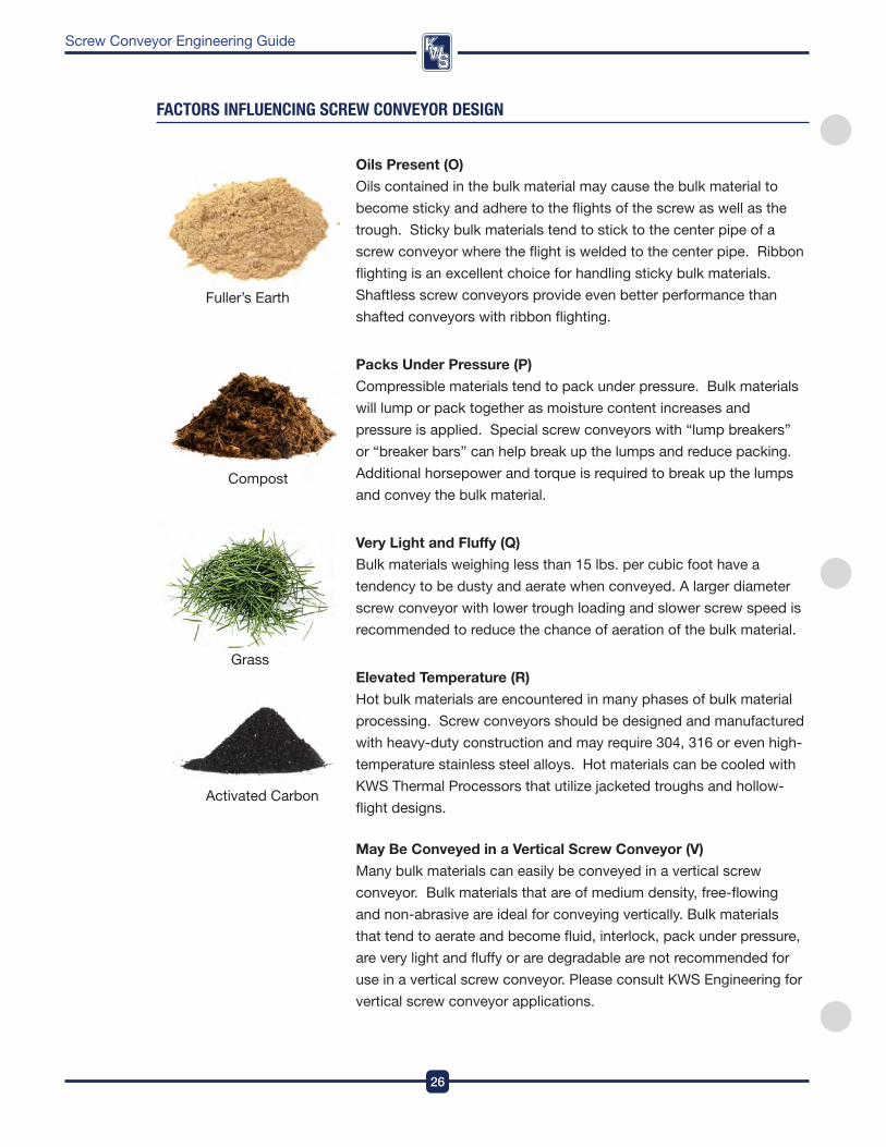
oils present (o)
oils contained in the bulk material may cause the bulk material to
become sticky and adhere to the flights of the screw as well as the
trough . Sticky bulk materials tend to stick to the center pipe of a
screw conveyor where the flight is welded to the center pipe . ribbon
flighting is an excellent choice for handling sticky bulk materials .
Shaftless screw conveyors provide even better performance than
shafted conveyors with ribbon flighting .
packs Under pressure (p)
Compressible materials tend to pack under pressure . Bulk materials
will lump or pack together as moisture content increases and
pressure is applied . Special screw conveyors with “lump breakers”
or “breaker bars” can help break up the lumps and reduce packing .
additional horsepower and torque is required to break up the lumps
and convey the bulk material .
Very light and fluffy (Q)
Bulk materials weighing less than 15 lbs . per cubic foot have a
tendency to be dusty and aerate when conveyed . a larger diameter
screw conveyor with lower trough loading and slower screw speed is
recommended to reduce the chance of aeration of the bulk material .
Elevated Temperature (R)
Hot bulk materials are encountered in many phases of bulk material
processing . Screw conveyors should be designed and manufactured
with heavy-duty construction and may require 304, 316 or even high-
temperature stainless steel alloys . Hot materials can be cooled with
kwS Thermal processors that utilize jacketed troughs and hollow-
flight designs .
May Be Conveyed in a Vertical Screw Conveyor (V)
Many bulk materials can easily be conveyed in a vertical screw
conveyor . Bulk materials that are of medium density, free-flowing
and non-abrasive are ideal for conveying vertically . Bulk materials
that tend to aerate and become fluid, interlock, pack under pressure,
are very light and fluffy or are degradable are not recommended for
use in a vertical screw conveyor . please consult kwS Engineering for
vertical screw conveyor applications .
Compost
fuller’s Earth
Grass
activated Carbon

27
DesignEngineeringManufacturing
Screw Conveyor Engineering Guide
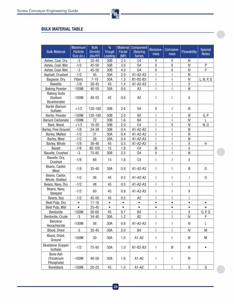
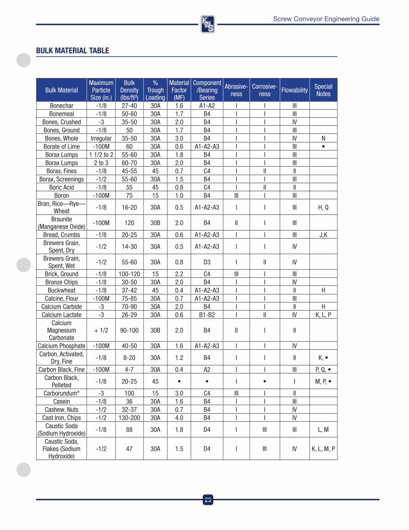
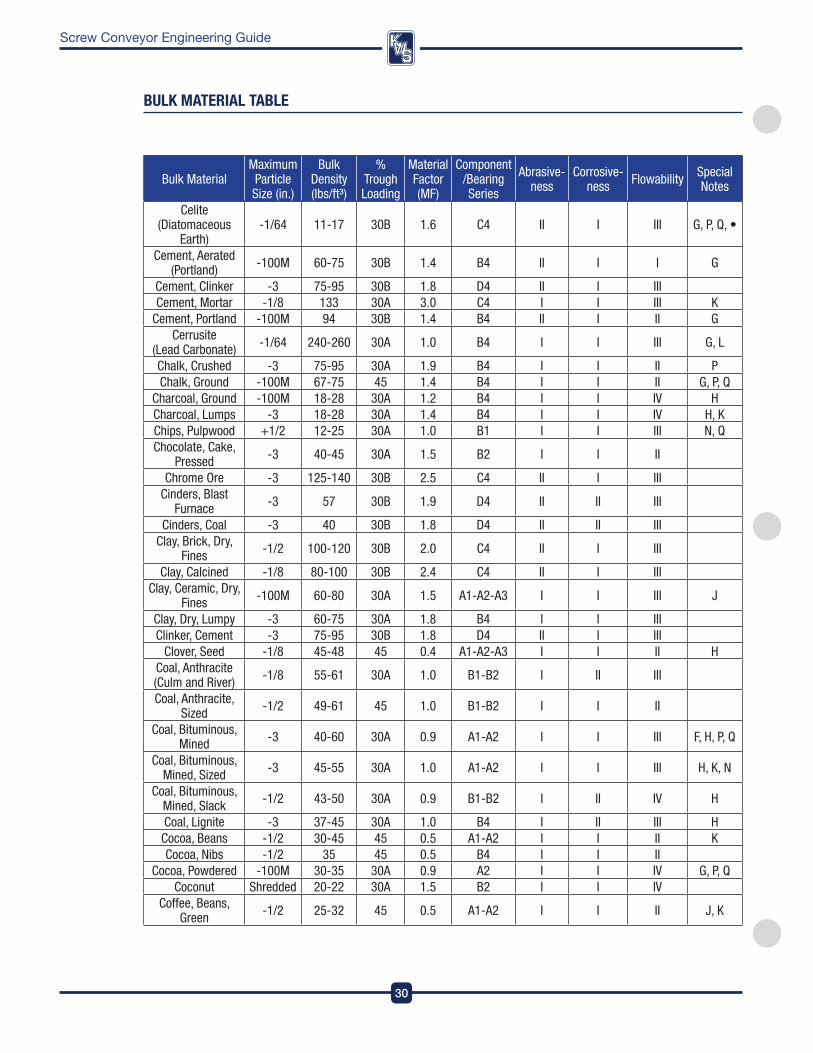
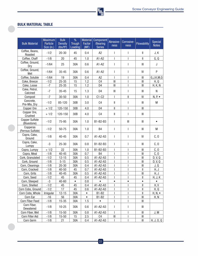
bUlK MaTeRIal Table
Bulk MaterialMaximum Particle Size (in.)
Bulk Density (lbs/ft³)
%Trough Loading
Material Factor (MF)
Component/Bearing Series
Abrasive- ness
Corrosive- ness Flowability Special
Notes
Acetylenogen (Calcium Carbide) + 1/2 70-90 30A 2.0 B4 I I II H
Adipic Acid -100M 45 30A 0.5 D3 I I III H, M, VAlfalfa Meal -1/8 14-22 30A 0.6 B4 I I IV O, Q, V
Alfalfa Pellets -1/2 41-43 45 0.5 B4 I I IIAlfalfa Seed -1/8 10-15 45 0.4 A1-A2-A3 I I I H
Almonds -1/2 28-30 30A 0.9 B4 I I III KAlum, Fines -1/8 45-50 30A 0.6 A1-A2-A3 I I III M, •
Alum, Lumpy + 1/2 50-60 30A 1.4 B1-B2 I I II •Alumina -1/8 55-65 15 1.8 C4 III I II G, Q
Alumina, Fines -100M 35 15 1.6 C4 III I II G, QAlumina, Sized or
Briquette -3 65 15 2.0 C4 III I III
Aluminate Gel (Aluminate Hydroxide)
-1/8 45 30A 1.7 B4 I I III V
Aluminum Chips, Dry -1/2 7-15 30A 1.2 B4 I I IV H, N
Aluminum Chips, Oily -1/2 7-15 30A 0.8 B4 I I IV N, Q, V
Aluminum Hydrate (Aluminum Hydroxide)
-1/2 13-20 30A 1.4 A1-A2-A3 I I III H, V
Aluminum Oxide -100M 60-120 15 1.8 C4 III I I G, HAluminum Ore
(Bauxite) -3 75-85 15 1.8 D4 III I II
Aluminum Silicate (Andalusite) -1/2 49 30A 0.8 C1-C2 I III III V
Aluminum Sulfate (Alum) -1/2 45-58 45 1.0 A1-A2-A3 I I II
Ammonium Chloride,
Crystalline-100M 45-52 30A 0.7 C1-C2 I III IV A, L
Ammonium Nitrate -1/8 45-62 30A 1.3 C3 I II III H, M, •Ammonium Sulfate -1/2 45-58 30A 1.0 A1-A2-A3 I II III A, I, M, •Antimony Powder -100M • 30A 1.6 B4 II I II V, •
Apple Pomace, Dry -1/2 15 30A 1.0 B4 I I IV Q, VArsenate of Lead (Lead Arsenate) -1/64 72 30A 1.4 A1-A2-A3 I I III G, L
Arsenic Oxide (Arsenolite) -100M 100-120 30A • • I • III L, •
Arsenic, Pulverized -100M 30 45 0.8 B4 I • II L, •Asbestos Rock, Ore -3 81 15 1.2 C4 III I III L
Asbestos, Shredded Fibers 20-40 30B 1.0 B4 II I IV L, P, Q
Ash, Black, Ground -1/8 105 30A 2.0 A1-A2-A3 I I IIIAshes, Coal, Dry -1/2 35-45 30B 3.0 C4 II II IV Q
DesignEngineeringManufacturing
28
Screw Conveyor Engineering Guide
Bulk MaterialMaximum Particle Size (in.)
Bulk Density (lbs/ft³)
%Trough Loading
Material Factor (MF)
Component/Bearing Series
Abrasive- ness
Corrosive- ness Flowability Special
Notes
Ashes, Coal, Dry -3 35-40 30B 2.5 C4 II II IV Ashes, Coal, Wet -1/2 45-50 30B 3.0 D4 II II IV PAshes, Coal, Wet -3 45-50 30B 4.0 D4 II II IV PAsphalt, Crushed -1/2 45 30A 2.0 A1-A2-A3 I I IV
Bagasse, Dry Fibers 7-10 30A 1.5 B1-B2-B3 I I IV L, N, P, QBakelite -1/8 30-45 45 1.4 A1-A2-A3 I I II
Baking Powder -100M 40-55 30A 0.6 A2 I I III Baking Soda
(Sodium Bicarbonate)
-100M 40-55 45 0.6 A2 I I II
Barite (Barium Sulfate) +1/2 120-180 30B 2.6 D4 II I III
Barite, Powder -100M 120-180 30B 2.0 B4 I I III G, PBarium Carbonate -100M 72 30B 1.6 B4 I I IV L
Bark, Wood +1/2 10-20 30B 2.0 C4 I II IV N, QBarley, Fine Ground -1/8 24-38 30B 0.4 A1-A2-A3 I I III
Barley, Malted -1/2 31 30A 0.4 A1-A2-A3 I I IIIBarley, Meal -1/2 28 30A 0.4 A1-A2-A3 I I IIIBarley, Whole -1/8 36-48 45 0.5 A1-A2-A3 I I II H
Basalt -1/8 80-105 15 1.8 C4 III I II Bauxite, Crushed -3 75-85 30B 2.5 D4 II I III
Bauxite, Dry, Crushed -1/8 68 15 1.8 C4 I I II
Beans, Castor, Meal -1/8 35-40 30A 0.8 A1-A2-A3 I I III O
Beans, Castor, Whole, Shelled -1/2 36 45 0.5 A1-A2-A3 I I I O
Beans, Navy, Dry -1/2 48 45 0.5 A1-A2-A3 I I I Beans, Navy,
Steeped -1/2 60 45 0.8 A1-A2-A3 I I II
Beans, Soy -1/2 45-50 45 0.5 A2 I I I Beet Pulp, Dry • 11-16 • • • • • • •Beet Pulp, Wet • 25-45 • • • • • • •
Bentonite -100M 50-60 45 0.7 B4 I I II G, P, QBentonite, Crude -3 34-40 30A 1.2 B2 I I IV P
Benzene Hexachloride -100M 56 30A 0.6 A1-A2-A3 I I IV L
Blood, Dried -3 35-45 30A 2.0 B4 I I IV MBlood, Dried,
Ground -100M 30 30A 1.0 A1-A2 I I III M
Bluestone (Copper Sulfate) -1/2 75-95 30A 1.0 B1-B2-B3 I III III •
Bone Ash (Tricalcium Phosphate)
-100M 40-50 30A 1.6 A1-A2 I I IV
Boneblack -100M 20-25 45 1.5 A1-A2 I I II Q
bUlK MaTeRIal Table
29
DesignEngineeringManufacturing
Screw Conveyor Engineering Guide
Bulk MaterialMaximum Particle Size (in.)
Bulk Density (lbs/ft³)
%Trough Loading
Material Factor (MF)
Component/Bearing Series
Abrasive- ness
Corrosive- ness Flowability Special
Notes
Bonechar -1/8 27-40 30A 1.6 A1-A2 I I III Bonemeal -1/8 50-60 30A 1.7 B4 I I III
Bones, Crushed -3 35-50 30A 2.0 B4 I I IV Bones, Ground -1/8 50 30A 1.7 B4 I I III Bones, Whole Irregular 35-50 30A 3.0 B4 I I IV NBorate of Lime -100M 60 30A 0.6 A1-A2-A3 I I III •Borax Lumps 1 1/2 to 2 55-60 30A 1.8 B4 I I III Borax Lumps 2 to 3 60-70 30A 2.0 B4 I I III Borax, Fines -1/8 45-55 45 0.7 C4 I II II
Borax, Screenings -1/2 55-60 30A 1.5 B4 I I IIIBoric Acid -1/8 55 45 0.8 C4 I II II
Boron -100M 75 15 1.0 B4 III I III Bran, Rice—Rye—
Wheat -1/8 16-20 30A 0.5 A1-A2-A3 I I III H, Q
Braunite (Manganese Oxide) -100M 120 30B 2.0 B4 II I III
Bread, Crumbs -1/8 20-25 30A 0.6 A1-A2-A3 I I III J,KBrewers Grain,
Spent, Dry -1/2 14-30 30A 0.5 A1-A2-A3 I I IV
Brewers Grain, Spent, Wet -1/2 55-60 30A 0.8 D3 I II IV
Brick, Ground -1/8 100-120 15 2.2 C4 III I IIIBronze Chips -1/8 30-50 30A 2.0 B4 I I IV Buckwheat -1/8 37-42 45 0.4 A1-A2-A3 I I II H
Calcine, Flour -100M 75-85 30A 0.7 A1-A2-A3 I I III Calcium Carbide -3 70-90 30A 2.0 B4 I I II HCalcium Lactate -3 26-29 30A 0.6 B1-B2 I II IV K, L, P
Calcium Magnesium Carbonate
+ 1/2 90-100 30B 2.0 B4 II I II
Calcium Phosphate -100M 40-50 30A 1.6 A1-A2-A3 I I IV Carbon, Activated,
Dry, Fine -1/8 8-20 30A 1.2 B4 I I II K, •
Carbon Black, Fine -100M 4-7 30A 0.4 A2 I I III P, Q, •Carbon Black,
Pelleted -1/8 20-25 45 • • I • I M, P, •
Carborundum* -3 100 15 3.0 C4 III I II Casein -1/8 36 30A 1.6 B4 I I III
Cashew, Nuts -1/2 32-37 30A 0.7 B4 I I IVCast Iron, Chips -1/2 130-200 30A 4.0 B4 I I IV
Caustic Soda (Sodium Hydroxide) -1/8 88 30A 1.8 D4 I III III L, M
Caustic Soda, Flakes (Sodium
Hydroxide)-1/2 47 30A 1.5 D4 I III IV K, L, M, P
bUlK MaTeRIal Table
DesignEngineeringManufacturing
30
Screw Conveyor Engineering Guide
Bulk MaterialMaximum Particle Size (in.)
Bulk Density (lbs/ft³)
%Trough Loading
Material Factor (MF)
Component/Bearing Series
Abrasive- ness
Corrosive- ness Flowability Special
Notes
Celite (Diatomaceous
Earth)-1/64 11-17 30B 1.6 C4 II I III G, P, Q, •
Cement, Aerated (Portland) -100M 60-75 30B 1.4 B4 II I I G
Cement, Clinker -3 75-95 30B 1.8 D4 II I III Cement, Mortar -1/8 133 30A 3.0 C4 I I III K
Cement, Portland -100M 94 30B 1.4 B4 II I II GCerrusite
(Lead Carbonate) -1/64 240-260 30A 1.0 B4 I I III G, L
Chalk, Crushed -3 75-95 30A 1.9 B4 I I II PChalk, Ground -100M 67-75 45 1.4 B4 I I II G, P, Q
Charcoal, Ground -100M 18-28 30A 1.2 B4 I I IV HCharcoal, Lumps -3 18-28 30A 1.4 B4 I I IV H, KChips, Pulpwood +1/2 12-25 30A 1.0 B1 I I III N, QChocolate, Cake,
Pressed -3 40-45 30A 1.5 B2 I I II
Chrome Ore -3 125-140 30B 2.5 C4 II I III Cinders, Blast
Furnace -3 57 30B 1.9 D4 II II III
Cinders, Coal -3 40 30B 1.8 D4 II II III Clay, Brick, Dry,
Fines -1/2 100-120 30B 2.0 C4 II I III
Clay, Calcined -1/8 80-100 30B 2.4 C4 II I IIIClay, Ceramic, Dry,
Fines -100M 60-80 30A 1.5 A1-A2-A3 I I III J
Clay, Dry, Lumpy -3 60-75 30A 1.8 B4 I I IIIClinker, Cement -3 75-95 30B 1.8 D4 II I III
Clover, Seed -1/8 45-48 45 0.4 A1-A2-A3 I I II HCoal, Anthracite (Culm and River) -1/8 55-61 30A 1.0 B1-B2 I II III
Coal, Anthracite, Sized -1/2 49-61 45 1.0 B1-B2 I I II
Coal, Bituminous, Mined -3 40-60 30A 0.9 A1-A2 I I III F, H, P, Q
Coal, Bituminous, Mined, Sized -3 45-55 30A 1.0 A1-A2 I I III H, K, N
Coal, Bituminous, Mined, Slack -1/2 43-50 30A 0.9 B1-B2 I II IV H
Coal, Lignite -3 37-45 30A 1.0 B4 I II III HCocoa, Beans -1/2 30-45 45 0.5 A1-A2 I I II KCocoa, Nibs -1/2 35 45 0.5 B4 I I II
Cocoa, Powdered -100M 30-35 30A 0.9 A2 I I IV G, P, QCoconut Shredded 20-22 30A 1.5 B2 I I IV
Coffee, Beans, Green -1/2 25-32 45 0.5 A1-A2 I I II J, K
bUlK MaTeRIal Table
31
DesignEngineeringManufacturing
Screw Conveyor Engineering Guide
Bulk MaterialMaximum Particle Size (in.)
Bulk Density (lbs/ft³)
%Trough Loading
Material Factor (MF)
Component/Bearing Series
Abrasive- ness
Corrosive- ness Flowability Special
Notes
Coffee, Beans, Roasted -1/2 20-30 45 0.4 A2 I I II J, K
Coffee, Chaff -1/8 20 45 1.0 A1-A2 I I II G, QCoffee, Ground,
Dry -1/64 25 30A 0.6 A1-A2 I I III J
Coffee, Ground, Wet -1/64 35-45 30A 0.6 A1-A2 I I IV P
Coffee, Soluble -1/64 19 30A 0.4 A2 I I III G,J,K,M,QCoke, Breeze -1/2 25-35 15 1.2 C4 III I III H, QCoke, Loose -7 25-35 15 1.2 D4 III I III H, K, NCoke, Petrol,
Calcined -7 35-45 15 1.3 D4 III I III N
Compost -7 30-50 30A 1.0 C1-C2 I II IV N, P, •Concrete,
Pre-Mix, Dry -1/2 85-120 30B 3.0 C4 II I III M
Copper Ore + 1/2 120-150 30B 4.0 D4 II I III Copper Ore,
Crushed + 1/2 120-150 30B 4.0 C4 II I III
Copper Sulfate (Bluestone) -1/2 75-95 30A 1.0 B1-B2-B3 I III III •
Copperas (Ferrous Sulfate) -1/2 50-75 30A 1.0 B4 I I III M
Copra, Cake, Ground -1/8 40-45 30A 0.7 A1-A2-A3 I I IV C, O
Copra, Cake, Lumpy -3 25-30 30A 0.8 B1-B2-B3 I I III C, O
Copra, Lumpy + 1/2 22 30A 1.0 B1-B2-B3 I I III C, OCopra, Meal -1/8 40-45 30A 0.7 B4 I I III C, O
Cork, Granulated -1/2 12-15 30A 0.5 A1-A2-A3 I I III D, V, QCork, Ground -1/8 5-15 30A 0.5 A1-A2-A3 I I III D, V, Q
Corn, Cleanings -1/8 20-30 30A 0.4 A1-A2-A3 I I III J, QCorn, Cracked -1/8 40-50 45 0.7 A1-A2-A3 I I II H, J
Corn, Grits -1/8 40-45 30A 0.5 A1-A2-A3 I I III H, JCorn, Seed -1/2 45 45 0.4 A1-A2-A3 I I II H, J, K
Corn, Steeped -3 40-60 • 0.8 • • • • •Corn, Shelled -1/2 45 45 0.4 A1-A2-A3 I I II H, V
Corn Cobs, Ground -1/2 17 45 0.6 A1-A2-A3 I I II H, QCorn Cobs, Whole Irregular 12-15 30A • B1-B2 I I II H, N, •
Corn Ear -16 56 30A • B1-B2 I I III H, NCorn Fiber Feed -1/8 15-35 30A 1.5 • I I III
Corn Fiber, Dewatered -1/8 10-25 30A 0.6 A1-A2-A3 I I III
Corn Fiber, Wet -1/8 15-50 30A 0.8 A1-A2-A3 I I III J, MCorn Filter Aid -1/8 15-50 15 2.5 C4 III I III
Corn Germ -1/8 21 30A 0.4 A1-A2-A3 I I III H, J, O, Q
bUlK MaTeRIal Table
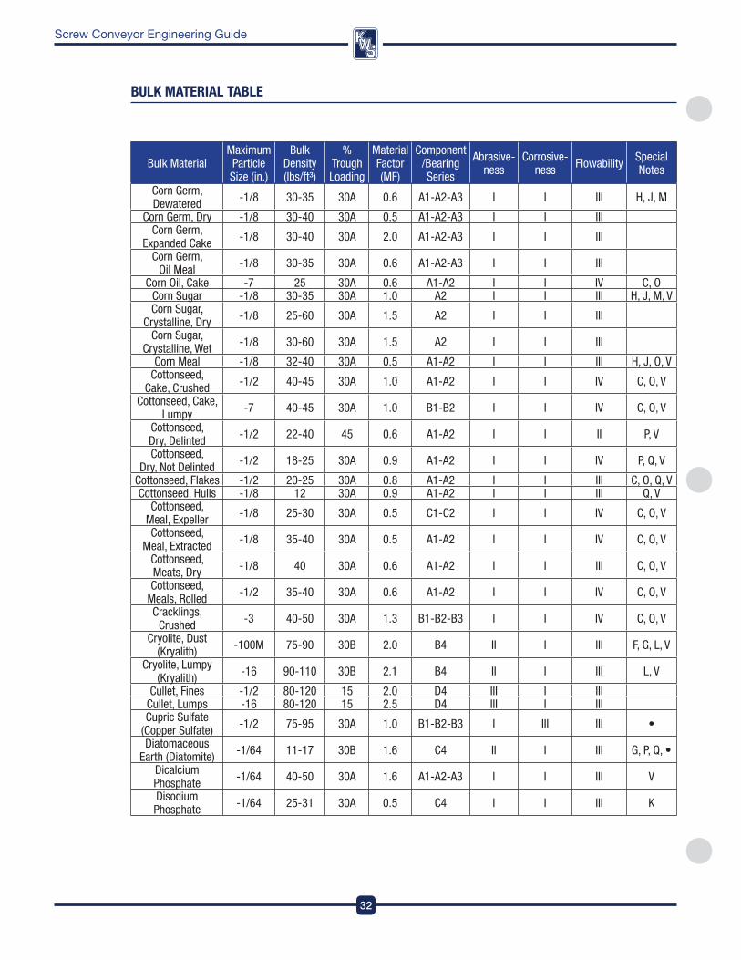
DesignEngineeringManufacturing
32
Screw Conveyor Engineering Guide
Bulk MaterialMaximum Particle Size (in.)
Bulk Density (lbs/ft³)
%Trough Loading
Material Factor (MF)
Component/Bearing Series
Abrasive- ness
Corrosive- ness Flowability Special
Notes
Corn Germ, Dewatered -1/8 30-35 30A 0.6 A1-A2-A3 I I III H, J, M
Corn Germ, Dry -1/8 30-40 30A 0.5 A1-A2-A3 I I IIICorn Germ,
Expanded Cake -1/8 30-40 30A 2.0 A1-A2-A3 I I III
Corn Germ, Oil Meal -1/8 30-35 30A 0.6 A1-A2-A3 I I III
Corn Oil, Cake -7 25 30A 0.6 A1-A2 I I IV C, OCorn Sugar -1/8 30-35 30A 1.0 A2 I I III H, J, M, VCorn Sugar,
Crystalline, Dry -1/8 25-60 30A 1.5 A2 I I III
Corn Sugar, Crystalline, Wet -1/8 30-60 30A 1.5 A2 I I III
Corn Meal -1/8 32-40 30A 0.5 A1-A2 I I III H, J, O, VCottonseed,
Cake, Crushed -1/2 40-45 30A 1.0 A1-A2 I I IV C, O, V
Cottonseed, Cake, Lumpy -7 40-45 30A 1.0 B1-B2 I I IV C, O, V
Cottonseed, Dry, Delinted -1/2 22-40 45 0.6 A1-A2 I I II P, V
Cottonseed, Dry, Not Delinted -1/2 18-25 30A 0.9 A1-A2 I I IV P, Q, V
Cottonseed, Flakes -1/2 20-25 30A 0.8 A1-A2 I I III C, O, Q, VCottonseed, Hulls -1/8 12 30A 0.9 A1-A2 I I III Q, V
Cottonseed, Meal, Expeller -1/8 25-30 30A 0.5 C1-C2 I I IV C, O, V
Cottonseed, Meal, Extracted -1/8 35-40 30A 0.5 A1-A2 I I IV C, O, V
Cottonseed, Meats, Dry -1/8 40 30A 0.6 A1-A2 I I III C, O, V
Cottonseed, Meals, Rolled -1/2 35-40 30A 0.6 A1-A2 I I IV C, O, V
Cracklings, Crushed -3 40-50 30A 1.3 B1-B2-B3 I I IV C, O, V
Cryolite, Dust (Kryalith) -100M 75-90 30B 2.0 B4 II I III F, G, L, V
Cryolite, Lumpy (Kryalith) -16 90-110 30B 2.1 B4 II I III L, V
Cullet, Fines -1/2 80-120 15 2.0 D4 III I III Cullet, Lumps -16 80-120 15 2.5 D4 III I IIICupric Sulfate
(Copper Sulfate) -1/2 75-95 30A 1.0 B1-B2-B3 I III III •
Diatomaceous Earth (Diatomite) -1/64 11-17 30B 1.6 C4 II I III G, P, Q, •
Dicalcium Phosphate -1/64 40-50 30A 1.6 A1-A2-A3 I I III V
Disodium Phosphate -1/64 25-31 30A 0.5 C4 I I III K
bUlK MaTeRIal Table
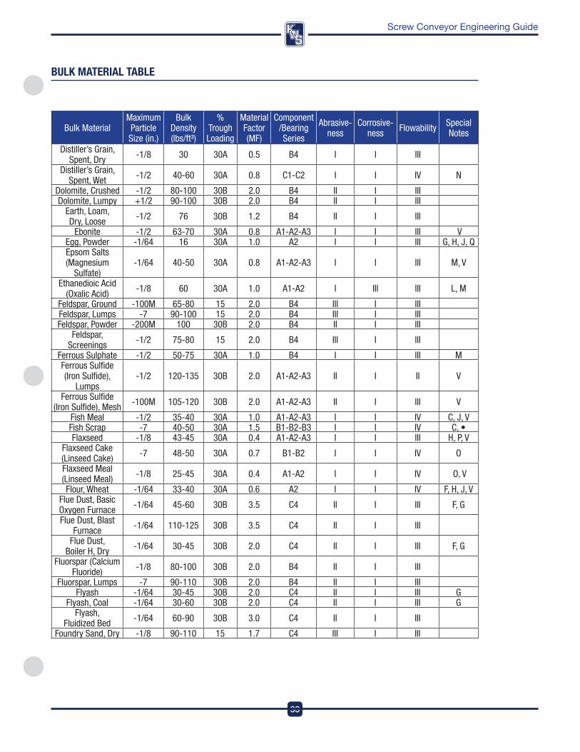
33
DesignEngineeringManufacturing
Screw Conveyor Engineering Guide
Bulk MaterialMaximum Particle Size (in.)
Bulk Density (lbs/ft³)
%Trough Loading
Material Factor (MF)
Component/Bearing Series
Abrasive- ness
Corrosive- ness Flowability Special
Notes
Distiller’s Grain, Spent, Dry -1/8 30 30A 0.5 B4 I I III
Distiller’s Grain, Spent, Wet -1/2 40-60 30A 0.8 C1-C2 I I IV N
Dolomite, Crushed -1/2 80-100 30B 2.0 B4 II I III Dolomite, Lumpy +1/2 90-100 30B 2.0 B4 II I III
Earth, Loam, Dry, Loose -1/2 76 30B 1.2 B4 II I III
Ebonite -1/2 63-70 30A 0.8 A1-A2-A3 I I III VEgg, Powder -1/64 16 30A 1.0 A2 I I III G, H, J, QEpsom Salts (Magnesium
Sulfate)-1/64 40-50 30A 0.8 A1-A2-A3 I I III M, V
Ethanedioic Acid (Oxalic Acid) -1/8 60 30A 1.0 A1-A2 I III III L, M
Feldspar, Ground -100M 65-80 15 2.0 B4 III I III Feldspar, Lumps -7 90-100 15 2.0 B4 III I III Feldspar, Powder -200M 100 30B 2.0 B4 II I III
Feldspar, Screenings -1/2 75-80 15 2.0 B4 III I III
Ferrous Sulphate -1/2 50-75 30A 1.0 B4 I I III MFerrous Sulfide (Iron Sulfide),
Lumps-1/2 120-135 30B 2.0 A1-A2-A3 II I II V
Ferrous Sulfide (Iron Sulfide), Mesh -100M 105-120 30B 2.0 A1-A2-A3 II I III V
Fish Meal -1/2 35-40 30A 1.0 A1-A2-A3 I I IV C, J, VFish Scrap -7 40-50 30A 1.5 B1-B2-B3 I I IV C, •Flaxseed -1/8 43-45 30A 0.4 A1-A2-A3 I I III H, P, V
Flaxseed Cake (Linseed Cake) -7 48-50 30A 0.7 B1-B2 I I IV O
Flaxseed Meal (Linseed Meal) -1/8 25-45 30A 0.4 A1-A2 I I IV O, V
Flour, Wheat -1/64 33-40 30A 0.6 A2 I I IV F, H, J, VFlue Dust, Basic Oxygen Furnace -1/64 45-60 30B 3.5 C4 II I III F, G
Flue Dust, Blast Furnace -1/64 110-125 30B 3.5 C4 II I III
Flue Dust, Boiler H, Dry -1/64 30-45 30B 2.0 C4 II I III F, G
Fluorspar (Calcium Fluoride) -1/8 80-100 30B 2.0 B4 II I III
Fluorspar, Lumps -7 90-110 30B 2.0 B4 II I IIIFlyash -1/64 30-45 30B 2.0 C4 II I III G
Flyash, Coal -1/64 30-60 30B 2.0 C4 II I III GFlyash,
Fluidized Bed -1/64 60-90 30B 3.0 C4 II I III
Foundry Sand, Dry -1/8 90-110 15 1.7 C4 III I III
bUlK MaTeRIal Table
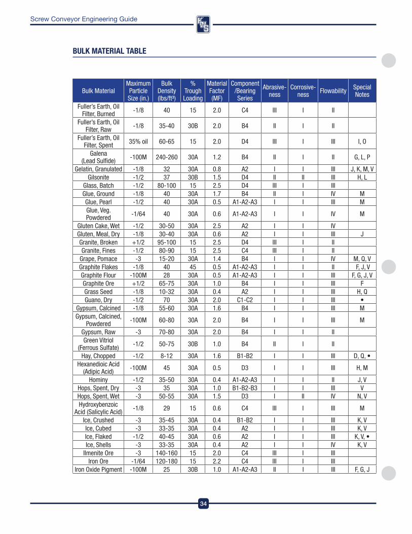
DesignEngineeringManufacturing
34
Screw Conveyor Engineering Guide
Bulk MaterialMaximum Particle Size (in.)
Bulk Density (lbs/ft³)
%Trough Loading
Material Factor (MF)
Component/Bearing Series
Abrasive- ness
Corrosive- ness Flowability Special
Notes
Fuller’s Earth, Oil Filter, Burned -1/8 40 15 2.0 C4 III I II
Fuller’s Earth, Oil Filter, Raw -1/8 35-40 30B 2.0 B4 II I II
Fuller’s Earth, Oil Filter, Spent 35% oil 60-65 15 2.0 D4 III I III I, O
Galena (Lead Sulfide) -100M 240-260 30A 1.2 B4 II I II G, L, P
Gelatin, Granulated -1/8 32 30A 0.8 A2 I I III J, K, M, VGilsonite -1/2 37 30B 1.5 D4 II II III H, L
Glass, Batch -1/2 80-100 15 2.5 D4 III I III Glue, Ground -1/8 40 30A 1.7 B4 II I IV MGlue, Pearl -1/2 40 30A 0.5 A1-A2-A3 I I III MGlue, Veg. Powdered -1/64 40 30A 0.6 A1-A2-A3 I I IV M
Gluten Cake, Wet -1/2 30-50 30A 2.5 A2 I I IVGluten, Meal, Dry -1/8 30-40 30A 0.6 A2 I I III JGranite, Broken +1/2 95-100 15 2.5 D4 III I II Granite, Fines -1/2 80-90 15 2.5 C4 III I II
Grape, Pomace -3 15-20 30A 1.4 B4 I I IV M, Q, VGraphite Flakes -1/8 40 45 0.5 A1-A2-A3 I I II F, J, VGraphite Flour -100M 28 30A 0.5 A1-A2-A3 I I III F, G, J, VGraphite Ore +1/2 65-75 30A 1.0 B4 I I III FGrass Seed -1/8 10-32 30A 0.4 A2 I I III H, QGuano, Dry -1/2 70 30A 2.0 C1-C2 I I III •
Gypsum, Calcined -1/8 55-60 30A 1.6 B4 I I III MGypsum, Calcined,
Powdered -100M 60-80 30A 2.0 B4 I I III M
Gypsum, Raw -3 70-80 30A 2.0 B4 I I IIGreen Vitriol
(Ferrous Sulfate) -1/2 50-75 30B 1.0 B4 II I II
Hay, Chopped -1/2 8-12 30A 1.6 B1-B2 I I III D, Q, •Hexanedioic Acid
(Adipic Acid) -100M 45 30A 0.5 D3 I I III H, M
Hominy -1/2 35-50 30A 0.4 A1-A2-A3 I I II J, VHops, Spent, Dry -3 35 30A 1.0 B1-B2-B3 I I III VHops, Spent, Wet -3 50-55 30A 1.5 D3 I II IV N, VHydroxybenzoic
Acid (Salicylic Acid) -1/8 29 15 0.6 C4 III I III M
Ice, Crushed -3 35-45 30A 0.4 B1-B2 I I III K, VIce, Cubed -3 33-35 30A 0.4 A2 I I III K, VIce, Flaked -1/2 40-45 30A 0.6 A2 I I III K, V, •Ice, Shells -3 33-35 30A 0.4 A2 I I IV K, V
Ilmenite Ore -3 140-160 15 2.0 C4 III I III Iron Ore -1/64 120-180 15 2.2 C4 III I III
Iron Oxide Pigment -100M 25 30B 1.0 A1-A2-A3 II I III F, G, J
bUlK MaTeRIal Table
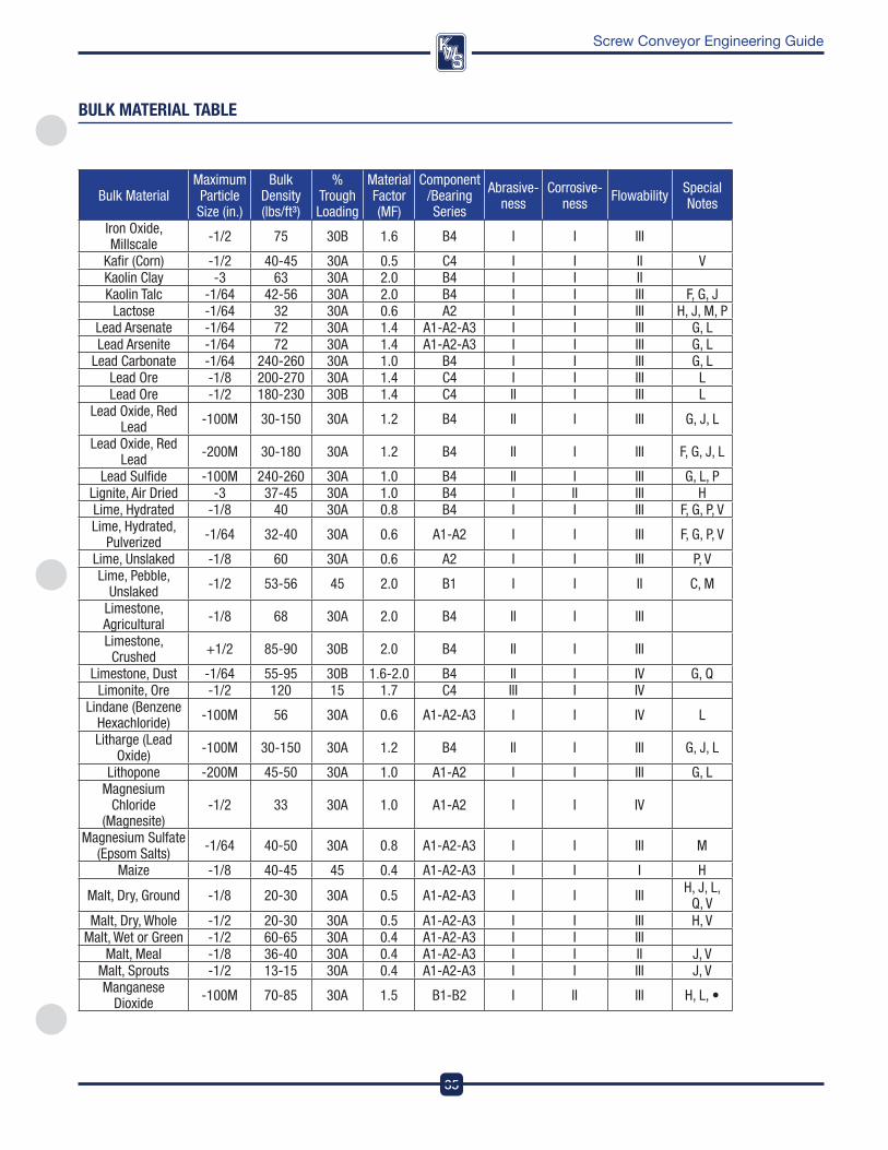
35
DesignEngineeringManufacturing
Screw Conveyor Engineering Guide
Bulk MaterialMaximum Particle Size (in.)
Bulk Density (lbs/ft³)
%Trough Loading
Material Factor (MF)
Component/Bearing Series
Abrasive- ness
Corrosive- ness Flowability Special
Notes
Iron Oxide, Millscale -1/2 75 30B 1.6 B4 I I III
Kafir (Corn) -1/2 40-45 30A 0.5 C4 I I II VKaolin Clay -3 63 30A 2.0 B4 I I II Kaolin Talc -1/64 42-56 30A 2.0 B4 I I III F, G, J
Lactose -1/64 32 30A 0.6 A2 I I III H, J, M, PLead Arsenate -1/64 72 30A 1.4 A1-A2-A3 I I III G, LLead Arsenite -1/64 72 30A 1.4 A1-A2-A3 I I III G, L
Lead Carbonate -1/64 240-260 30A 1.0 B4 I I III G, LLead Ore -1/8 200-270 30A 1.4 C4 I I III LLead Ore -1/2 180-230 30B 1.4 C4 II I III L
Lead Oxide, Red Lead -100M 30-150 30A 1.2 B4 II I III G, J, L
Lead Oxide, Red Lead -200M 30-180 30A 1.2 B4 II I III F, G, J, L
Lead Sulfide -100M 240-260 30A 1.0 B4 II I III G, L, PLignite, Air Dried -3 37-45 30A 1.0 B4 I II III HLime, Hydrated -1/8 40 30A 0.8 B4 I I III F, G, P, V Lime, Hydrated,
Pulverized -1/64 32-40 30A 0.6 A1-A2 I I III F, G, P, V
Lime, Unslaked -1/8 60 30A 0.6 A2 I I III P, VLime, Pebble,
Unslaked -1/2 53-56 45 2.0 B1 I I II C, M
Limestone, Agricultural -1/8 68 30A 2.0 B4 II I III
Limestone, Crushed +1/2 85-90 30B 2.0 B4 II I III
Limestone, Dust -1/64 55-95 30B 1.6-2.0 B4 II I IV G, QLimonite, Ore -1/2 120 15 1.7 C4 III I IV
Lindane (Benzene Hexachloride) -100M 56 30A 0.6 A1-A2-A3 I I IV L
Litharge (Lead Oxide) -100M 30-150 30A 1.2 B4 II I III G, J, L
Lithopone -200M 45-50 30A 1.0 A1-A2 I I III G, LMagnesium
Chloride (Magnesite)
-1/2 33 30A 1.0 A1-A2 I I IV
Magnesium Sulfate (Epsom Salts) -1/64 40-50 30A 0.8 A1-A2-A3 I I III M
Maize -1/8 40-45 45 0.4 A1-A2-A3 I I I H
Malt, Dry, Ground -1/8 20-30 30A 0.5 A1-A2-A3 I I III H, J, L, Q, V
Malt, Dry, Whole -1/2 20-30 30A 0.5 A1-A2-A3 I I III H, VMalt, Wet or Green -1/2 60-65 30A 0.4 A1-A2-A3 I I III
Malt, Meal -1/8 36-40 30A 0.4 A1-A2-A3 I I II J, VMalt, Sprouts -1/2 13-15 30A 0.4 A1-A2-A3 I I III J, VManganese
Dioxide -100M 70-85 30A 1.5 B1-B2 I II III H, L, •
bUlK MaTeRIal Table
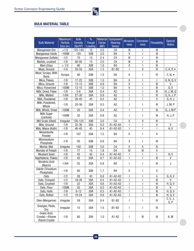
DesignEngineeringManufacturing
36
Screw Conveyor Engineering Guide
Bulk MaterialMaximum Particle Size (in.)
Bulk Density (lbs/ft³)
%Trough Loading
Material Factor (MF)
Component/Bearing Series
Abrasive- ness
Corrosive- ness Flowability Special
Notes
Manganese Ore +1/2 125-140 15 2.0 C4 III I III Manganese Oxide -100M 120 30B 2.0 B4 II I III
Manganese Sulfate -1/2 70 15 2.4 C4 III I III Marble, crushed -1/8 80-95 15 2.0 C4 III I III
Marl (Clay) + 1/2 80 30B 1.6 B4 II I III Meat, Ground -1/4 50-55 30A 1.5 B1-B2 I II IV C, K, P, •
Meat, Scraps, With Bone Scraps 40 30B 1.5 D4 II I IV C, N, •
Mica, Flakes -1/8 17-22 30B 1.0 B4 II I I G, N, Q, VMica, Ground -1/8 13-15 30B 0.9 B4 II I III V
Mica, Pulverized -100M 13-15 30B 1.0 B4 II I III G, VMilk, Dried, Flake -1/8 5-6 30A 0.4 A2 I I III H, J, M, Q
Milk, Malted -1/64 27-30 30A 0.9 A2 I I IV G, H, J, PMilk, Powdered -1/8 20-45 45 0.5 A2 I I II G, H, JMilk, Powdered,
Whole -1/8 20-36 30A 0.5 A2 I I III J, M, P
Milk, Whole, Dried -100M 20 30A 0.4 A2 I I III G, J, M PMilk Sugar (Lactose) -100M 32 30A 0.8 A2 I I III H, J, P
Mill Scale (Steel) Irregular 120-125 30B 3.0 C4 II II IVMilo, Ground -1/8 32-36 30A 0.5 A1-A2-A3 I I II V
Milo, Maize (Kafir) -1/8 40-45 45 0.4 A1-A2-A3 I I I H, VMolybdenite
Powder -1/8 107 30A 1.5 B4 II I II
Monosodium Phosphate -1/8 50 30B 0.6 B4 II I III
Mortar, Wet Irregular 150 30B 3.0 C4 II II IVMuriate of Potash -1/8 77 15 1.8 D4 III III II
Mustard Seed -1/8 45 45 0.4 A1-A2-A3 I I I H, VNaphtalene, Flakes -1/8 45 30A 0.7 A1-A2-A3 I I III V
Nicotinic Acid (Niacin) -1/64 35 30A 0.8 B4 I I III J
Oakite (Trisodium Phosphate) -1/8 60 30B 1.7 B4 II I II
Oats -1/2 26 45 0.6 A1-A2-A3 I I Ii G, H, VOats, Crimped -1/2 19-26 30A 0.5 A1-A2-A3 I I III VOats, Crushed -1/8 22 30A 0.6 A1-A2-A3 I I IV H, Q, V
Oats, Flour -100M 35 30A 0.5 A1-A2-A3 I I III VOats, Hulls -1/8 8-12 30A 0.5 A1-A2-A3 I I III H, Q, VOats, Rolled -1/2 19-24 30A 0.6 A1-A2-A3 I I III H, Q, V
Oleo (Margarine) Irregular 59 30A 0.4 B1-B2 I I IV C, E, J, O, P
Oranges, Peels, Dry Irregular 15 30A 1.5 B1-B2 I I IV
Oxalic Acid, Crystal—Ethane
Diacid Crystal-1/8 60 30A 1.0 A1-A2 I III III K, M
bUlK MaTeRIal Table
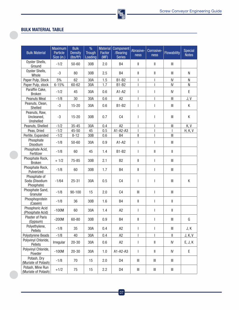
37
DesignEngineeringManufacturing
Screw Conveyor Engineering Guide
Bulk MaterialMaximum Particle Size (in.)
Bulk Density (lbs/ft³)
%Trough Loading
Material Factor (MF)
Component/Bearing Series
Abrasive- ness
Corrosive- ness Flowability Special
Notes
Oyster Shells, Ground -1/2 50-60 30B 2.0 B4 II II III
Oyster Shells, Whole -3 80 30B 2.5 B4 II II III N
Paper Pulp, Stock 5% 62 30A 1.5 B1-B2 I I IV NPaper Pulp, stock 6-15% 60-62 30A 1.7 B1-B2 I I IV N
Paraffin Cake, Broken -1/2 45 30A 0.6 A1-A2 I I IV E
Peanuts Meal -1/8 30 30A 0.6 A2 I I III J, VPeanuts, Clean,
Shelled -3 15-20 30A 0.6 B1-B2 I I III K
Peanuts, Raw, Uncleaned, Unshelled
-3 15-20 30B 0.7 C4 I I III K
Peanuts, Shelled -1/2 35-45 30A 0.4 A2 I I III K, VPeas, Dried -1/2 45-50 45 0.5 A1-A2-A3 I I I H, K, V
Perlite, Expanded -1/2 8-12 30B 0.6 B4 II I IIIPhosphate Disodium -1/8 50-60 30A 0.9 A1-A2 I I III
Phosphate Acid, Fertilizer -1/8 60 45 1.4 B1-B2 I II II
Phosphate Rock, Broken + 1/2 75-85 30B 2.1 B2 II I III
Phosphate Rock, Pulverized -1/8 60 30B 1.7 B4 II I III
Phosphate of Soda (Disodium
Phosphate)-1/64 25-31 30A 0.5 C4 I I III K
Phosphate Sand, Granular -1/8 90-100 15 2.0 C4 III I III
Phosphoprotein (Casein) -1/8 36 30B 1.6 B4 II I II
Phosphoric Acid (Phosphate Acid) -100M 60 30A 1.4 A2 I I II
Plaster of Paris (Gypsum) -200M 60-80 30B 0.9 B4 II I III G
Polyethylene, Pellets -1/8 35 30A 0.4 A2 I I III J, K
Polystyrene Beads -1/8 40 30A 0.4 A2 I I II J, K, VPolyvinyl Chloride,
Pellets Irregular 20-30 30A 0.6 A2 I II IV E, J, K
Polyvinyl Chloride, Powder -100M 20-30 30A 1.0 A1-A2-A3 I II IV E
Potash, Dry (Muriate of Potash) -1/8 70 15 2.0 D4 III III III
Potash, Mine Run (Muriate of Potash) +1/2 75 15 2.2 D4 III III III
bUlK MaTeRIal Table
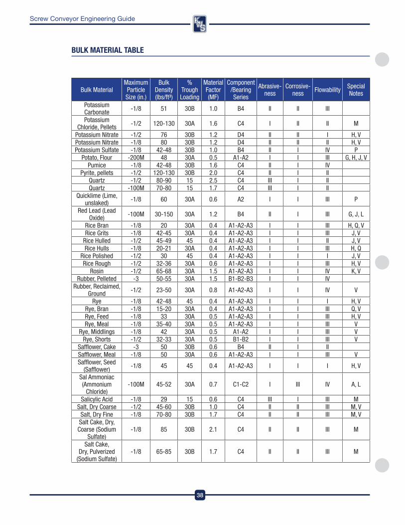
DesignEngineeringManufacturing
38
Screw Conveyor Engineering Guide
Bulk MaterialMaximum Particle Size (in.)
Bulk Density (lbs/ft³)
%Trough Loading
Material Factor (MF)
Component/Bearing Series
Abrasive- ness
Corrosive- ness Flowability Special
Notes
Potassium Carbonate -1/8 51 30B 1.0 B4 II II III
Potassium Chloride, Pellets -1/2 120-130 30A 1.6 C4 I II II M
Potassium Nitrate -1/2 76 30B 1.2 D4 II II I H, VPotassium Nitrate -1/8 80 30B 1.2 D4 II II II H, VPotassium Sulfate -1/8 42-48 30B 1.0 B4 II I IV P
Potato, Flour -200M 48 30A 0.5 A1-A2 I I III G, H, J, VPumice -1/8 42-48 30B 1.6 C4 II I IV
Pyrite, pellets -1/2 120-130 30B 2.0 C4 II I II Quartz -1/2 80-90 15 2.5 C4 III I II Quartz -100M 70-80 15 1.7 C4 III I II
Quicklime (Lime, unslaked) -1/8 60 30A 0.6 A2 I I III P
Red Lead (Lead Oxide) -100M 30-150 30A 1.2 B4 II I III G, J, L
Rice Bran -1/8 20 30A 0.4 A1-A2-A3 I I III H, Q, VRice Grits -1/8 42-45 30A 0.4 A1-A2-A3 I I III J, V
Rice Hulled -1/2 45-49 45 0.4 A1-A2-A3 I I II J, VRice Hulls -1/8 20-21 30A 0.4 A1-A2-A3 I I III H, Q
Rice Polished -1/2 30 45 0.4 A1-A2-A3 I I I J, VRice Rough -1/2 32-36 30A 0.6 A1-A2-A3 I I III H, V
Rosin -1/2 65-68 30A 1.5 A1-A2-A3 I I IV K, VRubber, Pelleted -3 50-55 30A 1.5 B1-B2-B3 I I IV
Rubber, Reclaimed, Ground -1/2 23-50 30A 0.8 A1-A2-A3 I I IV V
Rye -1/8 42-48 45 0.4 A1-A2-A3 I I I H, VRye, Bran -1/8 15-20 30A 0.4 A1-A2-A3 I I III Q, VRye, Feed -1/8 33 30A 0.5 A1-A2-A3 I I III H, VRye, Meal -1/8 35-40 30A 0.5 A1-A2-A3 I I III V
Rye, Middlings -1/8 42 30A 0.5 A1-A2 I I III VRye, Shorts -1/2 32-33 30A 0.5 B1-B2 I I III V
Safflower, Cake -3 50 30B 0.6 B4 II I II Safflower, Meal -1/8 50 30A 0.6 A1-A2-A3 I I III VSafflower, Seed
(Safflower) -1/8 45 45 0.4 A1-A2-A3 I I I H, V
Sal Ammoniac (Ammonium
Chloride)-100M 45-52 30A 0.7 C1-C2 I III IV A, L
Salicylic Acid -1/8 29 15 0.6 C4 III I III MSalt, Dry Coarse -1/2 45-60 30B 1.0 C4 II II III M, V
Salt, Dry Fine -1/8 70-80 30B 1.7 C4 II II III M, VSalt Cake, Dry, Coarse (Sodium
Sulfate)-1/8 85 30B 2.1 C4 II II III M
Salt Cake, Dry, Pulverized
(Sodium Sulfate)-1/8 65-85 30B 1.7 C4 II II III M
bUlK MaTeRIal Table
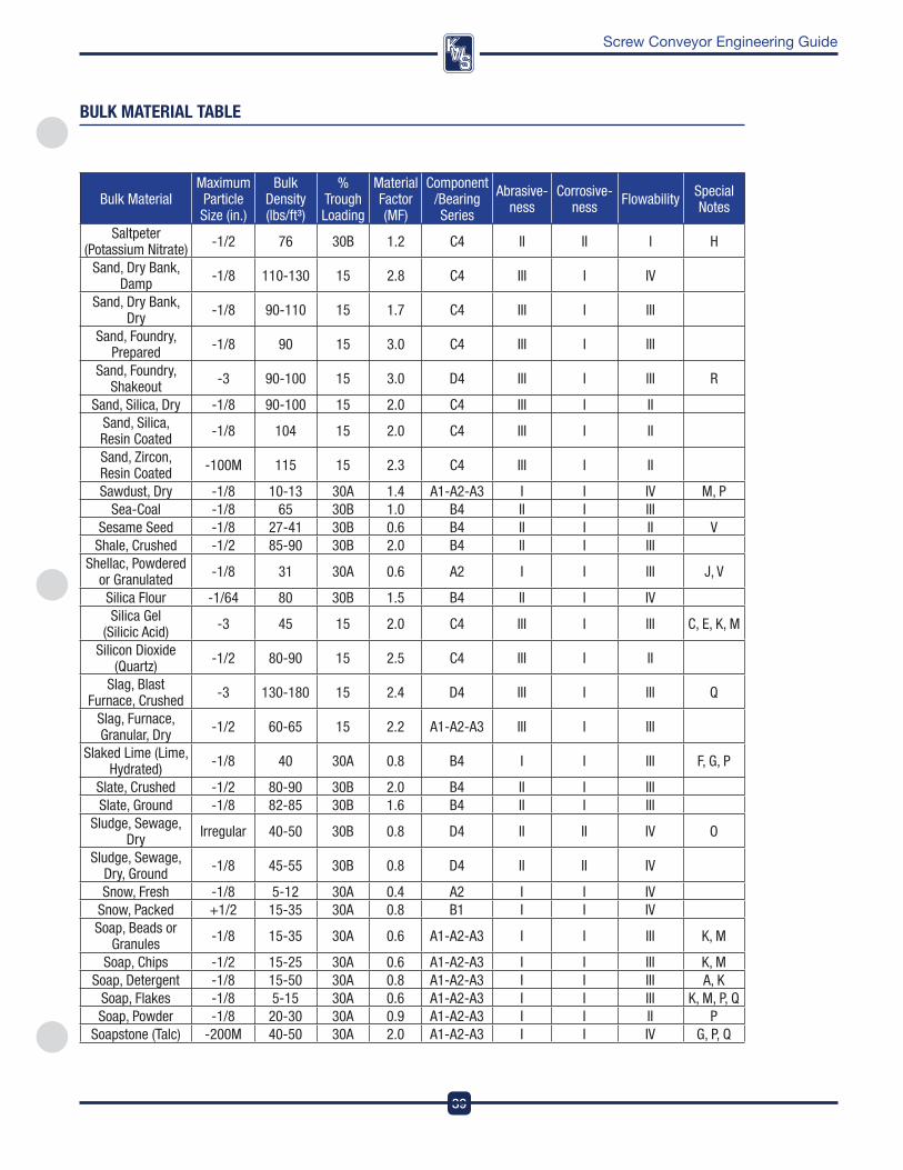
39
DesignEngineeringManufacturing
Screw Conveyor Engineering Guide
Bulk MaterialMaximum Particle Size (in.)
Bulk Density (lbs/ft³)
%Trough Loading
Material Factor (MF)
Component/Bearing Series
Abrasive- ness
Corrosive- ness Flowability Special
Notes
Saltpeter (Potassium Nitrate) -1/2 76 30B 1.2 C4 II II I H
Sand, Dry Bank, Damp -1/8 110-130 15 2.8 C4 III I IV
Sand, Dry Bank, Dry -1/8 90-110 15 1.7 C4 III I III
Sand, Foundry, Prepared -1/8 90 15 3.0 C4 III I III
Sand, Foundry, Shakeout -3 90-100 15 3.0 D4 III I III R
Sand, Silica, Dry -1/8 90-100 15 2.0 C4 III I II Sand, Silica, Resin Coated -1/8 104 15 2.0 C4 III I II
Sand, Zircon, Resin Coated -100M 115 15 2.3 C4 III I II
Sawdust, Dry -1/8 10-13 30A 1.4 A1-A2-A3 I I IV M, PSea-Coal -1/8 65 30B 1.0 B4 II I III
Sesame Seed -1/8 27-41 30B 0.6 B4 II I II VShale, Crushed -1/2 85-90 30B 2.0 B4 ll I III
Shellac, Powdered or Granulated -1/8 31 30A 0.6 A2 I I III J, V
Silica Flour -1/64 80 30B 1.5 B4 II I IVSilica Gel
(Silicic Acid) -3 45 15 2.0 C4 III I III C, E, K, M
Silicon Dioxide (Quartz) -1/2 80-90 15 2.5 C4 III I II
Slag, Blast Furnace, Crushed -3 130-180 15 2.4 D4 III I III Q
Slag, Furnace, Granular, Dry -1/2 60-65 15 2.2 A1-A2-A3 III I III
Slaked Lime (Lime, Hydrated) -1/8 40 30A 0.8 B4 I I III F, G, P
Slate, Crushed -1/2 80-90 30B 2.0 B4 II I III Slate, Ground -1/8 82-85 30B 1.6 B4 II I III
Sludge, Sewage, Dry Irregular 40-50 30B 0.8 D4 II II IV O
Sludge, Sewage, Dry, Ground -1/8 45-55 30B 0.8 D4 II II IV
Snow, Fresh -1/8 5-12 30A 0.4 A2 I I IV Snow, Packed +1/2 15-35 30A 0.8 B1 I I IV Soap, Beads or
Granules -1/8 15-35 30A 0.6 A1-A2-A3 I I III K, M
Soap, Chips -1/2 15-25 30A 0.6 A1-A2-A3 I I III K, MSoap, Detergent -1/8 15-50 30A 0.8 A1-A2-A3 I I III A, K
Soap, Flakes -1/8 5-15 30A 0.6 A1-A2-A3 I I III K, M, P, QSoap, Powder -1/8 20-30 30A 0.9 A1-A2-A3 I I II P
Soapstone (Talc) -200M 40-50 30A 2.0 A1-A2-A3 I I IV G, P, Q
bUlK MaTeRIal Table
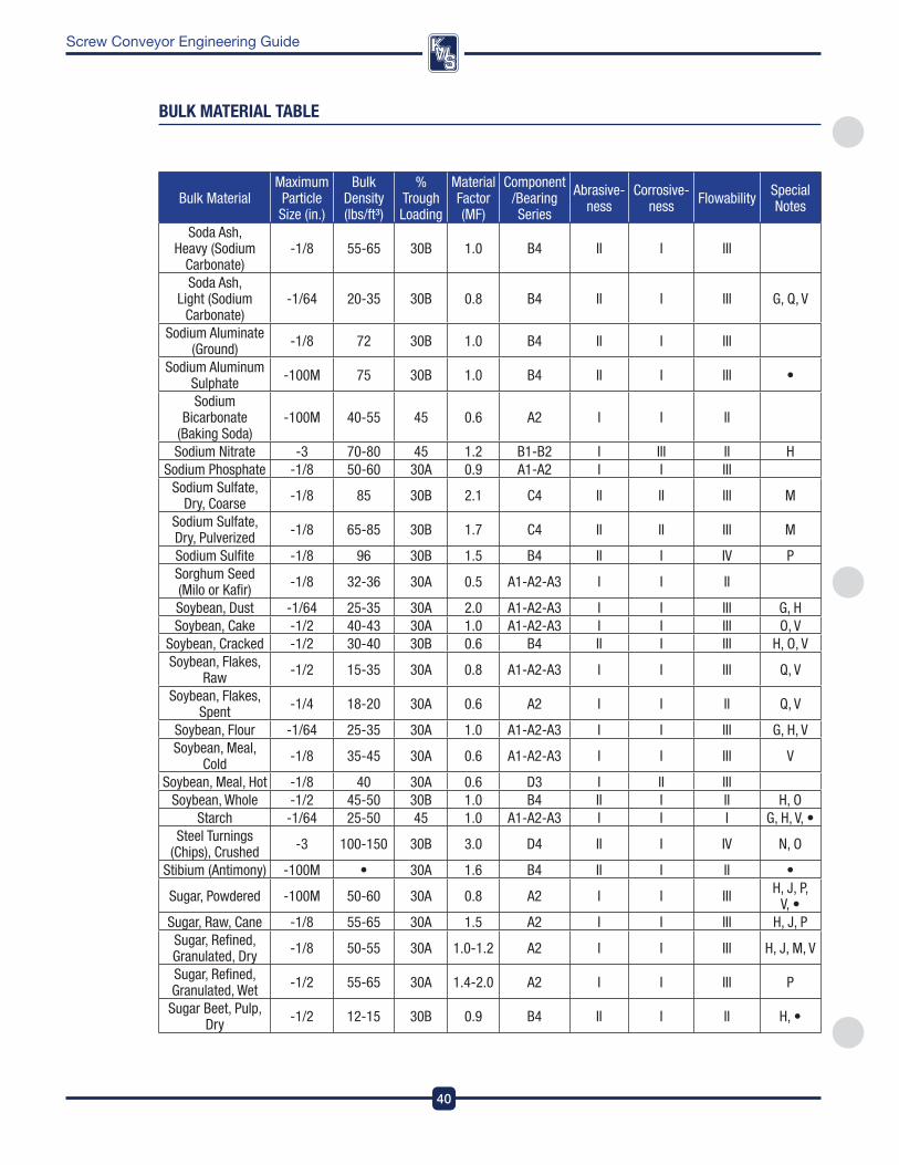
DesignEngineeringManufacturing
40
Screw Conveyor Engineering Guide
Bulk MaterialMaximum Particle Size (in.)
Bulk Density (lbs/ft³)
%Trough Loading
Material Factor (MF)
Component/Bearing Series
Abrasive- ness
Corrosive- ness Flowability Special
Notes
Soda Ash, Heavy (Sodium
Carbonate)-1/8 55-65 30B 1.0 B4 II I III
Soda Ash, Light (Sodium
Carbonate)-1/64 20-35 30B 0.8 B4 II I III G, Q, V
Sodium Aluminate (Ground) -1/8 72 30B 1.0 B4 II I III
Sodium Aluminum Sulphate -100M 75 30B 1.0 B4 II I III •
Sodium Bicarbonate
(Baking Soda)-100M 40-55 45 0.6 A2 I I II
Sodium Nitrate -3 70-80 45 1.2 B1-B2 I III II HSodium Phosphate -1/8 50-60 30A 0.9 A1-A2 I I III
Sodium Sulfate, Dry, Coarse -1/8 85 30B 2.1 C4 II II III M
Sodium Sulfate, Dry, Pulverized -1/8 65-85 30B 1.7 C4 II II III M
Sodium Sulfite -1/8 96 30B 1.5 B4 II I IV PSorghum Seed (Milo or Kafir) -1/8 32-36 30A 0.5 A1-A2-A3 I I II
Soybean, Dust -1/64 25-35 30A 2.0 A1-A2-A3 I I III G, HSoybean, Cake -1/2 40-43 30A 1.0 A1-A2-A3 I I III O, V
Soybean, Cracked -1/2 30-40 30B 0.6 B4 II I III H, O, VSoybean, Flakes,
Raw -1/2 15-35 30A 0.8 A1-A2-A3 I I III Q, V
Soybean, Flakes, Spent -1/4 18-20 30A 0.6 A2 I I II Q, V
Soybean, Flour -1/64 25-35 30A 1.0 A1-A2-A3 I I III G, H, VSoybean, Meal,
Cold -1/8 35-45 30A 0.6 A1-A2-A3 I I III V
Soybean, Meal, Hot -1/8 40 30A 0.6 D3 I II IIISoybean, Whole -1/2 45-50 30B 1.0 B4 II I II H, O
Starch -1/64 25-50 45 1.0 A1-A2-A3 I I I G, H, V, •Steel Turnings
(Chips), Crushed -3 100-150 30B 3.0 D4 II I IV N, O
Stibium (Antimony) -100M • 30A 1.6 B4 II I II •
Sugar, Powdered -100M 50-60 30A 0.8 A2 I I III H, J, P, V, •
Sugar, Raw, Cane -1/8 55-65 30A 1.5 A2 I I III H, J, PSugar, Refined, Granulated, Dry -1/8 50-55 30A 1.0-1.2 A2 I I III H, J, M, V
Sugar, Refined, Granulated, Wet -1/2 55-65 30A 1.4-2.0 A2 I I III P
Sugar Beet, Pulp, Dry -1/2 12-15 30B 0.9 B4 II I II H, •
bUlK MaTeRIal Table
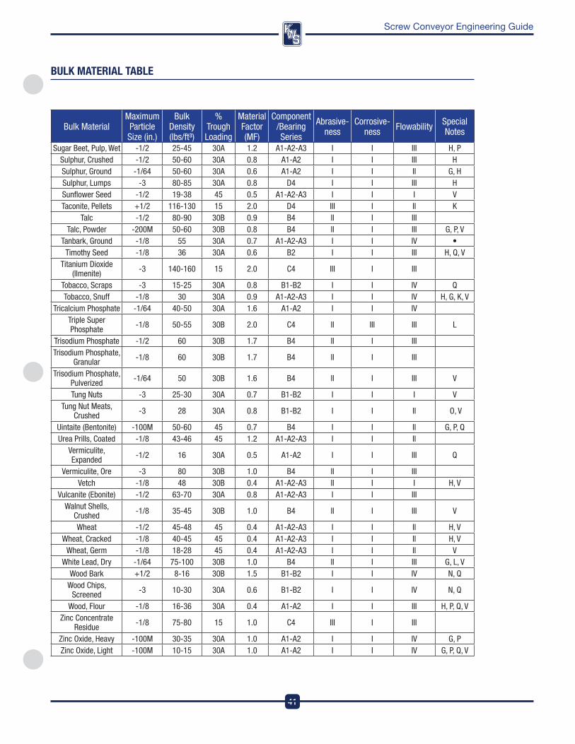
41
DesignEngineeringManufacturing
Screw Conveyor Engineering Guide
Bulk MaterialMaximum Particle Size (in.)
Bulk Density (lbs/ft³)
%Trough Loading
Material Factor (MF)
Component/Bearing Series
Abrasive- ness
Corrosive- ness Flowability Special
Notes
Sugar Beet, Pulp, Wet -1/2 25-45 30A 1.2 A1-A2-A3 I I III H, PSulphur, Crushed -1/2 50-60 30A 0.8 A1-A2 I I III HSulphur, Ground -1/64 50-60 30A 0.6 A1-A2 I I II G, HSulphur, Lumps -3 80-85 30A 0.8 D4 I I III HSunflower Seed -1/2 19-38 45 0.5 A1-A2-A3 I I I VTaconite, Pellets +1/2 116-130 15 2.0 D4 III I II K
Talc -1/2 80-90 30B 0.9 B4 II I III Talc, Powder -200M 50-60 30B 0.8 B4 II I III G, P, V
Tanbark, Ground -1/8 55 30A 0.7 A1-A2-A3 I I IV •Timothy Seed -1/8 36 30A 0.6 B2 I I III H, Q, V
Titanium Dioxide (llmenite) -3 140-160 15 2.0 C4 III I III
Tobacco, Scraps -3 15-25 30A 0.8 B1-B2 I I IV QTobacco, Snuff -1/8 30 30A 0.9 A1-A2-A3 I I IV H, G, K, V
Tricalcium Phosphate -1/64 40-50 30A 1.6 A1-A2 I I IV Triple Super Phosphate -1/8 50-55 30B 2.0 C4 II III III L
Trisodium Phosphate -1/2 60 30B 1.7 B4 II I III Trisodium Phosphate,
Granular -1/8 60 30B 1.7 B4 II I III
Trisodium Phosphate, Pulverized -1/64 50 30B 1.6 B4 II I III V
Tung Nuts -3 25-30 30A 0.7 B1-B2 I I I VTung Nut Meats,
Crushed -3 28 30A 0.8 B1-B2 I I II O, V
Uintaite (Bentonite) -100M 50-60 45 0.7 B4 I I II G, P, QUrea Prills, Coated -1/8 43-46 45 1.2 A1-A2-A3 I I II
Vermiculite, Expanded -1/2 16 30A 0.5 A1-A2 I I III Q
Vermiculite, Ore -3 80 30B 1.0 B4 II I III Vetch -1/8 48 30B 0.4 A1-A2-A3 II I I H, V
Vulcanite (Ebonite) -1/2 63-70 30A 0.8 A1-A2-A3 I I III Walnut Shells,
Crushed -1/8 35-45 30B 1.0 B4 II I III V
Wheat -1/2 45-48 45 0.4 A1-A2-A3 I I II H, VWheat, Cracked -1/8 40-45 45 0.4 A1-A2-A3 I I II H, V
Wheat, Germ -1/8 18-28 45 0.4 A1-A2-A3 I I II VWhite Lead, Dry -1/64 75-100 30B 1.0 B4 II I III G, L, V
Wood Bark +1/2 8-16 30B 1.5 B1-B2 I I IV N, QWood Chips,
Screened -3 10-30 30A 0.6 B1-B2 I I IV N, Q
Wood, Flour -1/8 16-36 30A 0.4 A1-A2 I I III H, P, Q, VZinc Concentrate
Residue -1/8 75-80 15 1.0 C4 III I III
Zinc Oxide, Heavy -100M 30-35 30A 1.0 A1-A2 I I IV G, PZinc Oxide, Light -100M 10-15 30A 1.0 A1-A2 I I IV G, P, Q, V
bUlK MaTeRIal Table
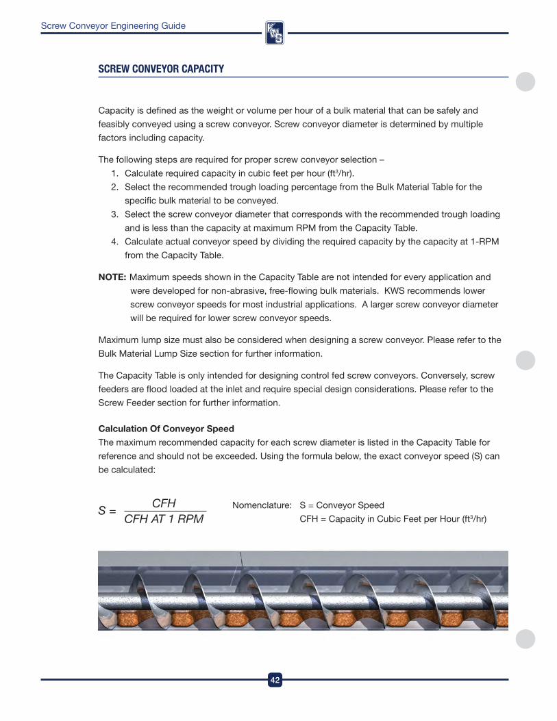
DesignEngineeringManufacturing
42
Screw Conveyor Engineering Guide
sCReW COnVeYOR CaPaCITY
Capacity is defined as the weight or volume per hour of a bulk material that can be safely and
feasibly conveyed using a screw conveyor . Screw conveyor diameter is determined by multiple
factors including capacity .
The following steps are required for proper screw conveyor selection –
1 . Calculate required capacity in cubic feet per hour (ft3/hr) .
2 . Select the recommended trough loading percentage from the Bulk Material Table for the
specific bulk material to be conveyed .
3 . Select the screw conveyor diameter that corresponds with the recommended trough loading
and is less than the capacity at maximum rpM from the Capacity Table .
4 . Calculate actual conveyor speed by dividing the required capacity by the capacity at 1-rpM
from the Capacity Table .
NoTE: Maximum speeds shown in the Capacity Table are not intended for every application and
were developed for non-abrasive, free-flowing bulk materials . kwS recommends lower
screw conveyor speeds for most industrial applications . a larger screw conveyor diameter
will be required for lower screw conveyor speeds .
Maximum lump size must also be considered when designing a screw conveyor . please refer to the
Bulk Material Lump Size section for further information .
The Capacity Table is only intended for designing control fed screw conveyors . Conversely, screw
feeders are flood loaded at the inlet and require special design considerations . please refer to the
Screw feeder section for further information .
Calculation of Conveyor Speed
The maximum recommended capacity for each screw diameter is listed in the Capacity Table for
reference and should not be exceeded . Using the formula below, the exact conveyor speed (S) can
be calculated:
nomenclature: S = Conveyor Speed
CfH = Capacity in Cubic feet per Hour (ft3/hr)
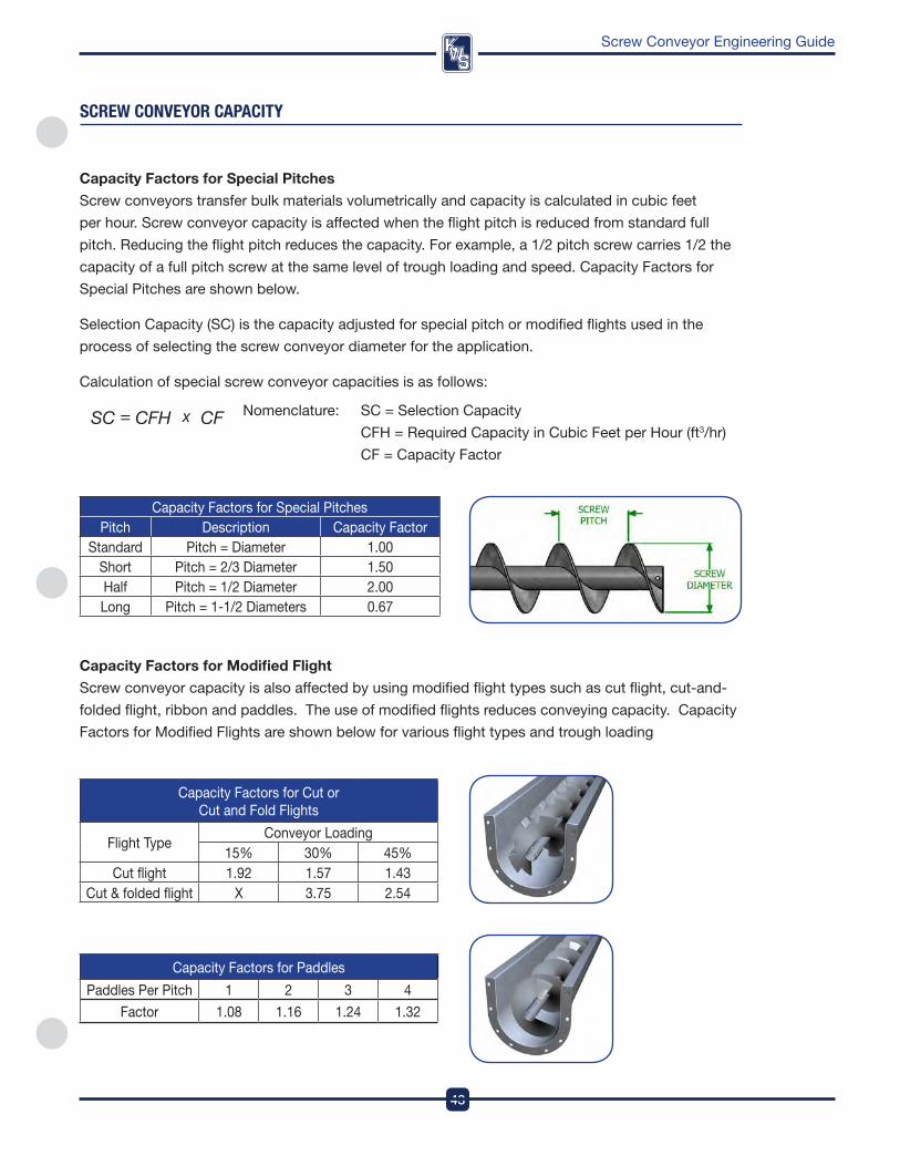
43
DesignEngineeringManufacturing
Screw Conveyor Engineering Guide
sCReW COnVeYOR CaPaCITY
Capacity factors for Special pitches
Screw conveyors transfer bulk materials volumetrically and capacity is calculated in cubic feet
per hour . Screw conveyor capacity is affected when the flight pitch is reduced from standard full
pitch . reducing the flight pitch reduces the capacity . for example, a 1/2 pitch screw carries 1/2 the
capacity of a full pitch screw at the same level of trough loading and speed . Capacity factors for
Special pitches are shown below .
Selection Capacity (SC) is the capacity adjusted for special pitch or modified flights used in the
process of selecting the screw conveyor diameter for the application .
Calculation of special screw conveyor capacities is as follows:
nomenclature: SC = Selection Capacity
CfH = required Capacity in Cubic feet per Hour (ft3/hr)
Cf = Capacity factor
Capacity factors for Special pitchespitch description Capacity factor
Standard pitch = diameter 1 .00Short pitch = 2/3 diameter 1 .50Half pitch = 1/2 diameter 2 .00Long pitch = 1-1/2 diameters 0 .67
Capacity factors for Modified flight
Screw conveyor capacity is also affected by using modified flight types such as cut flight, cut-and-
folded flight, ribbon and paddles . The use of modified flights reduces conveying capacity . Capacity
factors for Modified flights are shown below for various flight types and trough loading
Capacity factors for Cut or Cut and fold flights
flight Type Conveyor Loading
15% 30% 45%Cut flight 1 .92 1 .57 1 .43
Cut & folded flight X 3 .75 2 .54
Capacity factors for paddles
paddles per pitch 1 2 3 4
factor 1 .08 1 .16 1 .24 1 .32
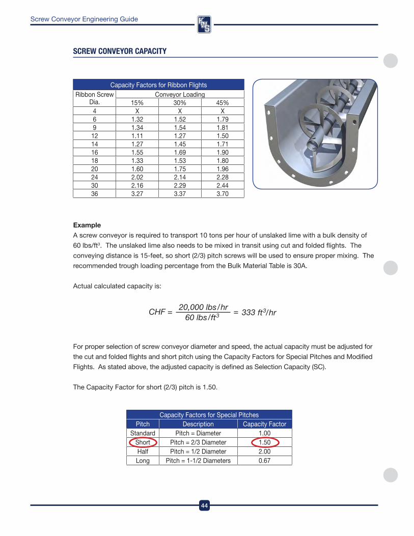
DesignEngineeringManufacturing
44
Screw Conveyor Engineering Guide
sCReW COnVeYOR CaPaCITY
Example
a screw conveyor is required to transport 10 tons per hour of unslaked lime with a bulk density of
60 lbs/ft3 . The unslaked lime also needs to be mixed in transit using cut and folded flights . The
conveying distance is 15-feet, so short (2/3) pitch screws will be used to ensure proper mixing . The
recommended trough loading percentage from the Bulk Material Table is 30a .
actual calculated capacity is:
Capacity factors for ribbon flightsribbon Screw
dia . Conveyor Loading
15% 30% 45%4 X X X6 1 .32 1 .52 1 .799 1 .34 1 .54 1 .8112 1 .11 1 .27 1 .5014 1 .27 1 .45 1 .7116 1 .55 1 .69 1 .9018 1 .33 1 .53 1 .8020 1 .60 1 .75 1 .9624 2 .02 2 .14 2 .2830 2 .16 2 .29 2 .4436 3 .27 3 .37 3 .70
for proper selection of screw conveyor diameter and speed, the actual capacity must be adjusted for
the cut and folded flights and short pitch using the Capacity factors for Special pitches and Modified
flights . as stated above, the adjusted capacity is defined as Selection Capacity (SC) .
The Capacity factor for short (2/3) pitch is 1 .50 .
Capacity factors for Special pitchespitch description Capacity factor
Standard pitch = diameter 1 .00Short pitch = 2/3 diameter 1 .50Half pitch = 1/2 diameter 2 .00Long pitch = 1-1/2 diameters 0 .67
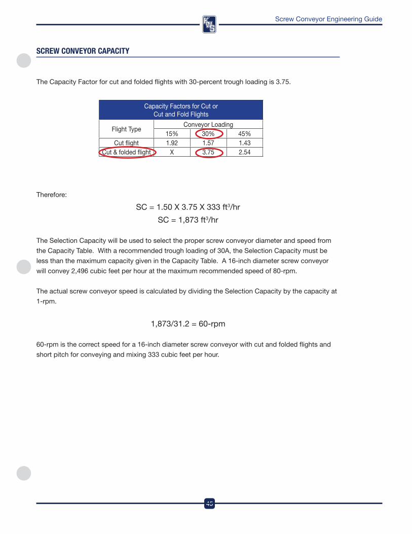
45
DesignEngineeringManufacturing
Screw Conveyor Engineering Guide
sCReW COnVeYOR CaPaCITY
Capacity factors for Cut or Cut and fold flights
flight Type Conveyor Loading
15% 30% 45%Cut flight 1 .92 1 .57 1 .43
Cut & folded flight X 3 .75 2 .54
The Capacity factor for cut and folded flights with 30-percent trough loading is 3 .75 .
Therefore:
SC = 1 .50 X 3 .75 X 333 ft3/hr
SC = 1,873 ft3/hr
The Selection Capacity will be used to select the proper screw conveyor diameter and speed from
the Capacity Table . with a recommended trough loading of 30a, the Selection Capacity must be
less than the maximum capacity given in the Capacity Table . a 16-inch diameter screw conveyor
will convey 2,496 cubic feet per hour at the maximum recommended speed of 80-rpm .
The actual screw conveyor speed is calculated by dividing the Selection Capacity by the capacity at
1-rpm .
1,873/31 .2 = 60-rpm
60-rpm is the correct speed for a 16-inch diameter screw conveyor with cut and folded flights and
short pitch for conveying and mixing 333 cubic feet per hour .
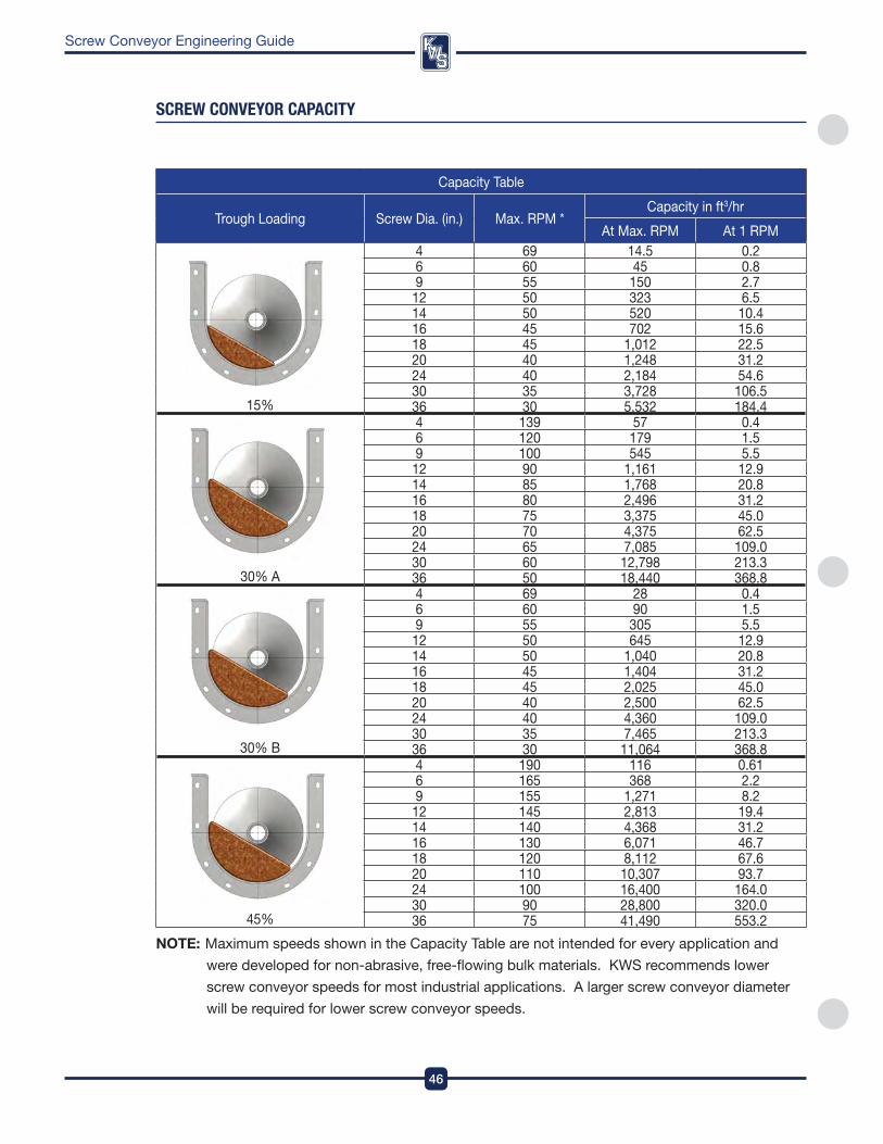
DesignEngineeringManufacturing
46
Screw Conveyor Engineering Guide
sCReW COnVeYOR CaPaCITY
Capacity Table
Trough Loading Screw dia . (in .) Max . rpM * Capacity in ft3/hr
at Max . rpM at 1 rpM
15%
4 69 14 .5 0 .26 60 45 0 .89 55 150 2 .7
12 50 323 6 .514 50 520 10 .416 45 702 15 .618 45 1,012 22 .520 40 1,248 31 .224 40 2,184 54 .630 35 3,728 106 .536 30 5,532 184 .4
30% a
4 139 57 0 .46 120 179 1 .59 100 545 5 .5
12 90 1,161 12 .914 85 1,768 20 .816 80 2,496 31 .218 75 3,375 45 .020 70 4,375 62 .524 65 7,085 109 .030 60 12,798 213 .336 50 18,440 368 .8
30% B
4 69 28 0 .46 60 90 1 .59 55 305 5 .5
12 50 645 12 .914 50 1,040 20 .816 45 1,404 31 .218 45 2,025 45 .020 40 2,500 62 .524 40 4,360 109 .030 35 7,465 213 .336 30 11,064 368 .8
45%
4 190 116 0 .616 165 368 2 .29 155 1,271 8 .2
12 145 2,813 19 .414 140 4,368 31 .216 130 6,071 46 .718 120 8,112 67 .620 110 10,307 93 .724 100 16,400 164 .030 90 28,800 320 .036 75 41,490 553 .2
NoTE: Maximum speeds shown in the Capacity Table are not intended for every application and
were developed for non-abrasive, free-flowing bulk materials . kwS recommends lower
screw conveyor speeds for most industrial applications . a larger screw conveyor diameter
will be required for lower screw conveyor speeds .
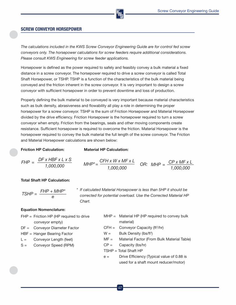
47
DesignEngineeringManufacturing
Screw Conveyor Engineering Guide
sCReW COnVeYOR HORsePOWeR
The calculations included in the KWS Screw Conveyor Engineering Guide are for control fed screw
conveyors only. The horsepower calculations for screw feeders require additional considerations.
Please consult KWS Engineering for screw feeder applications.
Horsepower is defined as the power required to safely and feasibly convey a bulk material a fixed
distance in a screw conveyor . The horsepower required to drive a screw conveyor is called Total
Shaft Horsepower, or TSHp . TSHp is a function of the characteristics of the bulk material being
conveyed and the friction inherent in the screw conveyor . it is very important to design a screw
conveyor with sufficient horsepower in order to prevent downtime and loss of production .
properly defining the bulk material to be conveyed is very important because material characteristics
such as bulk density, abrasiveness and flowability all play a role in determining the proper
horsepower for a screw conveyor . TSHp is the sum of friction Horsepower and Material Horsepower
divided by the drive efficiency . friction Horsepower is the horsepower required to turn a screw
conveyor when empty . friction from the bearings, seals and other moving components create
resistance . Sufficient horsepower is required to overcome the friction . Material Horsepower is the
horsepower required to convey the bulk material the full length of the screw conveyor . The friction
and Material Horsepower calculations are shown below:
friction Hp Calculation: Material Hp Calculation:
Total Shaft Hp Calculation:
* If calculated Material Horsepower is less than 5HP it should be
corrected for potential overload. Use the Corrected Material HP
Chart.
Equation Nomenclature:
fHp = friction Hp (Hp required to drive
conveyor empty)
df = Conveyor diameter factor
HBf = Hanger Bearing factor
L = Conveyor Length (feet)
S = Conveyor Speed (rpM)
MHp = Material Hp (Hp required to convey bulk
material)
CfH = Conveyor Capacity (ft3/hr)
w = Bulk density (lbs/ft3)
Mf = Material factor (from Bulk Material Table)
Cp = Capacity (lbs/hr)
TSHp = Total Shaft Hp
e = drive Efficiency (Typical value of 0 .88 is
used for a shaft mount reducer/motor)
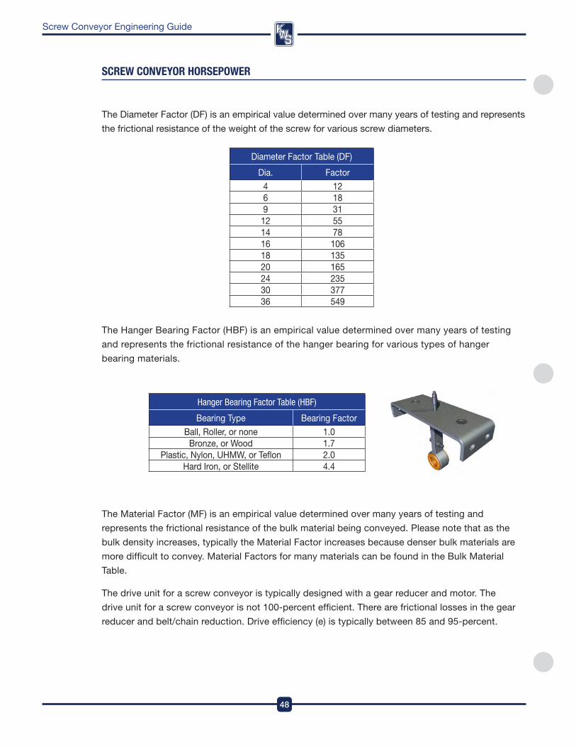
DesignEngineeringManufacturing
48
Screw Conveyor Engineering Guide
sCReW COnVeYOR HORsePOWeR
Hanger Bearing Factor Table (HBF)
Bearing Type Bearing factor
Ball, roller, or none 1 .0Bronze, or wood 1 .7
plastic, nylon, UHMw, or Teflon 2 .0Hard iron, or Stellite 4 .4
diameter factor Table (df)
dia . factor
4 126 189 31
12 5514 7816 10618 13520 16524 23530 37736 549
The diameter factor (df) is an empirical value determined over many years of testing and represents
the frictional resistance of the weight of the screw for various screw diameters .
The Hanger Bearing factor (HBf) is an empirical value determined over many years of testing
and represents the frictional resistance of the hanger bearing for various types of hanger
bearing materials .
The Material factor (Mf) is an empirical value determined over many years of testing and
represents the frictional resistance of the bulk material being conveyed . please note that as the
bulk density increases, typically the Material factor increases because denser bulk materials are
more difficult to convey . Material factors for many materials can be found in the Bulk Material
Table .
The drive unit for a screw conveyor is typically designed with a gear reducer and motor . The
drive unit for a screw conveyor is not 100-percent efficient . There are frictional losses in the gear
reducer and belt/chain reduction . drive efficiency (e) is typically between 85 and 95-percent .
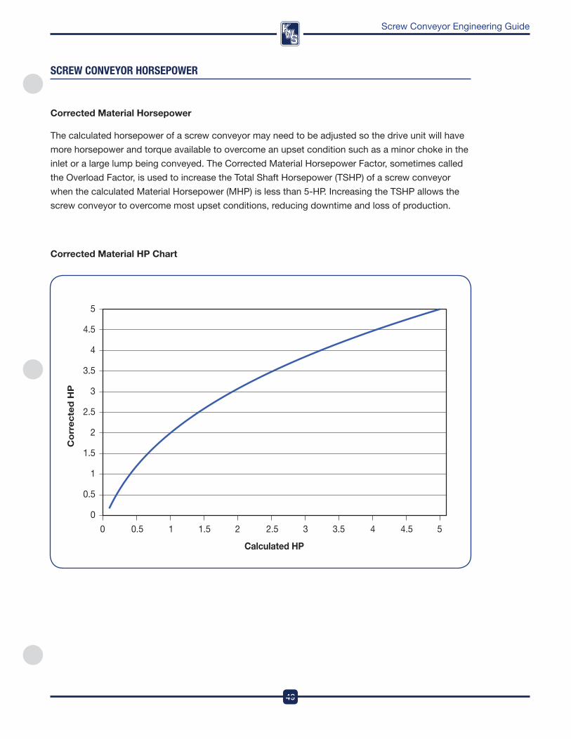
49
DesignEngineeringManufacturing
Screw Conveyor Engineering Guide
Calculated HP
0 0.5 1 1.5 2 2.5 3 3.5 4 4.5 5
Cor
rect
ed H
P
5
4.5
4
3.5
3
2.5
2
1.5
1
0.5
0
Corrected Material Hp Chart
sCReW COnVeYOR HORsePOWeR
Corrected Material Horsepower
The calculated horsepower of a screw conveyor may need to be adjusted so the drive unit will have
more horsepower and torque available to overcome an upset condition such as a minor choke in the
inlet or a large lump being conveyed . The Corrected Material Horsepower factor, sometimes called
the overload factor, is used to increase the Total Shaft Horsepower (TSHp) of a screw conveyor
when the calculated Material Horsepower (MHp) is less than 5-Hp . increasing the TSHp allows the
screw conveyor to overcome most upset conditions, reducing downtime and loss of production .
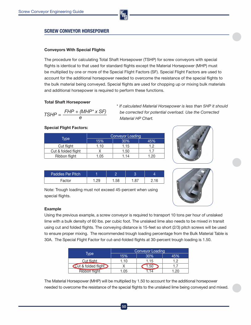
DesignEngineeringManufacturing
50
Screw Conveyor Engineering Guide
sCReW COnVeYOR HORsePOWeR
Conveyors With Special flights
The procedure for calculating Total Shaft Horsepower (TSHp) for screw conveyors with special
flights is identical to that used for standard flights except the Material Horsepower (MHp) must
be multiplied by one or more of the Special flight factors (Sf) . Special flight factors are used to
account for the additional horsepower needed to overcome the resistance of the special flights to
the bulk material being conveyed . Special flights are used for chopping up or mixing bulk materials
and additional horsepower is required to perform these functions .
Total Shaft Horsepower * If calculated Material Horsepower is less than 5HP it should
be corrected for potential overload. Use the Corrected
Material HP Chart.
Special flight factors:
TypeConveyor Loading
15% 30% 45%Cut flight 1 .10 1 .15 1 .2
Cut & folded flight X 1 .50 1 .7ribbon flight 1 .05 1 .14 1 .20
paddles per pitch 1 2 3 4
factor 1 .29 1 .58 1 .87 2 .16
note: Trough loading must not exceed 45-percent when using
special flights .
Example
Using the previous example, a screw conveyor is required to transport 10 tons per hour of unslaked
lime with a bulk density of 60 lbs . per cubic foot . The unslaked lime also needs to be mixed in transit
using cut and folded flights . The conveying distance is 15-feet so short (2/3) pitch screws will be used
to ensure proper mixing . The recommended trough loading percentage from the Bulk Material Table is
30a . The Special flight factor for cut-and-folded flights at 30-percent trough loading is 1 .50 .
The Material Horsepower (MHp) will be multiplied by 1 .50 to account for the additional horsepower
needed to overcome the resistance of the special flights to the unslaked lime being conveyed and mixed .
TypeConveyor Loading
15% 30% 45%Cut flight 1 .10 1 .15 1 .2
Cut & folded flight X 1 .50 1 .7ribbon flight 1 .05 1 .14 1 .20
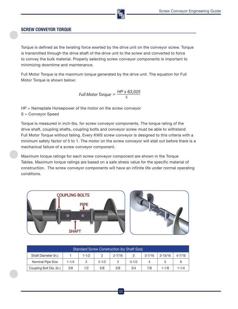
51
DesignEngineeringManufacturing
Screw Conveyor Engineering Guide
sCReW COnVeYOR TORqUe
Torque is defined as the twisting force exerted by the drive unit on the conveyor screw . Torque
is transmitted through the drive shaft of the drive unit to the screw and converted to force
to convey the bulk material . properly selecting screw conveyor components is important to
minimizing downtime and maintenance .
full Motor Torque is the maximum torque generated by the drive unit . The equation for full
Motor Torque is shown below:
Hp = nameplate Horsepower of the motor on the screw conveyor
S = Conveyor Speed
Torque is measured in inch-lbs . for screw conveyor components . The torque rating of the
drive shaft, coupling shafts, coupling bolts and conveyor screw must be able to withstand
full Motor Torque without failing . Every kwS screw conveyor is designed to this criteria with a
minimum safety factor of 5 to 1 . The motor on the screw conveyor will stall out before there is a
mechanical failure of a screw conveyor component .
Maximum torque ratings for each screw conveyor component are shown in the Torque
Tables . Maximum torque ratings are based on a safe stress value for the specific material of
construction . The screw conveyor components will have an infinite life under normal operating
conditions .
Standard Screw Construction (by Shaft Size)
Shaft diameter (in .) 1 1-1/2 2 2-7/16 3 3-7/16 3-15/16 4-7/16
nominal pipe Size 1-1/4 2 2-1/2 3 3-1/2 4 5 6
Coupling Bolt dia . (in .) 3/8 1/2 5/8 5/8 3/4 7/8 1-1/8 1-1/4
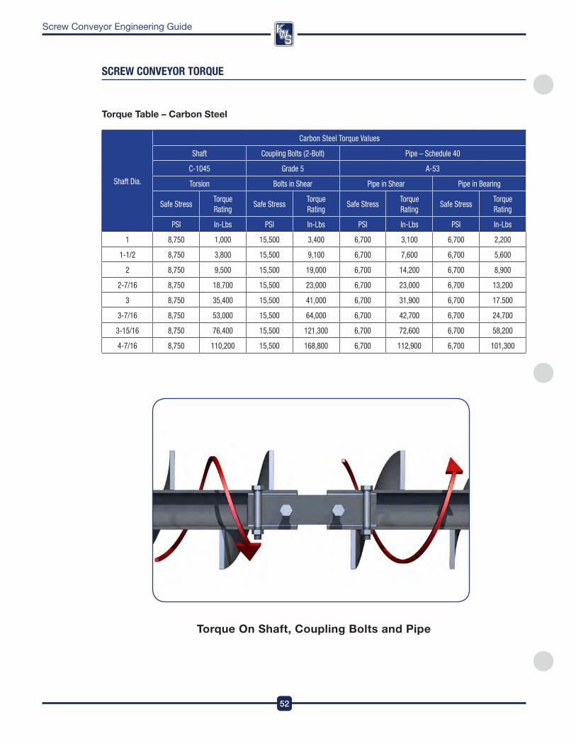
DesignEngineeringManufacturing
52
Screw Conveyor Engineering Guide
sCReW COnVeYOR TORqUe
Shaft Dia.
Carbon Steel Torque Values
Shaft Coupling Bolts (2-Bolt) Pipe – Schedule 40
C-1045 Grade 5 A-53
Torsion Bolts in Shear Pipe in Shear Pipe in Bearing
Safe StressTorque Rating
Safe StressTorque Rating
Safe StressTorque Rating
Safe StressTorque Rating
PSI In-Lbs PSI In-Lbs PSI In-Lbs PSI In-Lbs
1 8,750 1,000 15,500 3,400 6,700 3,100 6,700 2,200
1-1/2 8,750 3,800 15,500 9,100 6,700 7,600 6,700 5,600
2 8,750 9,500 15,500 19,000 6,700 14,200 6,700 8,900
2-7/16 8,750 18,700 15,500 23,000 6,700 23,000 6,700 13,200
3 8,750 35,400 15,500 41,000 6,700 31,900 6,700 17.500
3-7/16 8,750 53,000 15,500 64,000 6,700 42,700 6,700 24,700
3-15/16 8,750 76,400 15,500 121,300 6,700 72,600 6,700 58,200
4-7/16 8,750 110,200 15,500 168,800 6,700 112,900 6,700 101,300
Torque Table – Carbon Steel
Torque on Shaft, Coupling Bolts and pipe
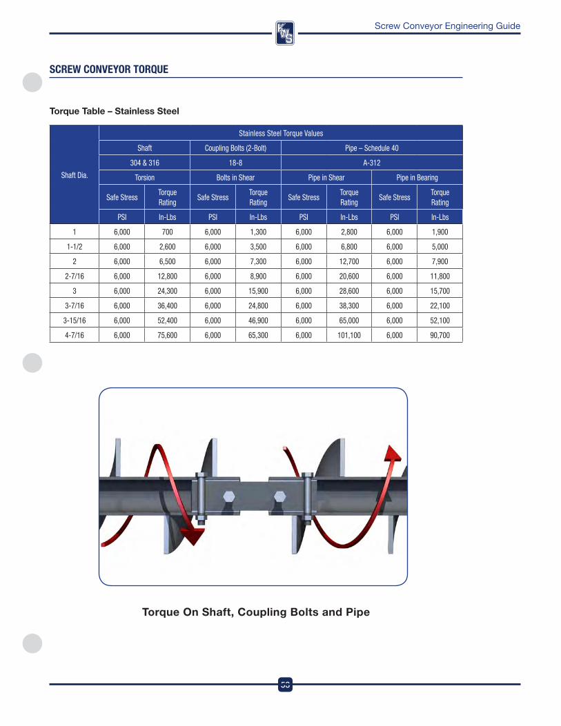
53
DesignEngineeringManufacturing
Screw Conveyor Engineering Guide
sCReW COnVeYOR TORqUe
Shaft Dia.
Stainless Steel Torque Values
Shaft Coupling Bolts (2-Bolt) Pipe – Schedule 40
304 & 316 18-8 A-312
Torsion Bolts in Shear Pipe in Shear Pipe in Bearing
Safe StressTorque Rating
Safe StressTorque Rating
Safe StressTorque Rating
Safe StressTorque Rating
PSI In-Lbs PSI In-Lbs PSI In-Lbs PSI In-Lbs
1 6,000 700 6,000 1,300 6,000 2,800 6,000 1,900
1-1/2 6,000 2,600 6,000 3,500 6,000 6,800 6,000 5,000
2 6,000 6,500 6,000 7,300 6,000 12,700 6,000 7,900
2-7/16 6,000 12,800 6,000 8,900 6,000 20,600 6,000 11,800
3 6,000 24,300 6,000 15,900 6,000 28,600 6,000 15,700
3-7/16 6,000 36,400 6,000 24,800 6,000 38,300 6,000 22,100
3-15/16 6,000 52,400 6,000 46,900 6,000 65,000 6,000 52,100
4-7/16 6,000 75,600 6,000 65,300 6,000 101,100 6,000 90,700
Torque Table – Stainless Steel
Torque on Shaft, Coupling Bolts and pipe
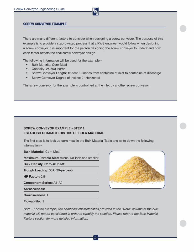
DesignEngineeringManufacturing
54
Screw Conveyor Engineering Guide
sCReW COnVeYOR eXaMPle
There are many different factors to consider when designing a screw conveyor . The purpose of this
example is to provide a step-by-step process that a kwS engineer would follow when designing
a screw conveyor . it is important for the person designing the screw conveyor to understand how
each factor affects the final screw conveyor design .
The following information will be used for the example –• BulkMaterial:CornMeal• Capacity:25,600lbs/hr• ScrewConveyorLength:16-feet,0-inchesfromcenterlineofinlettocenterlineofdischarge
• ScrewConveyorDegreeofIncline:0°Horizontal
The screw conveyor for the example is control fed at the inlet by another screw conveyor .
SCREW CoNVEYoR ExAMplE - STEp 1:
ESTABlISH CHARACTERISTICS of BUlK MATERIAl
The first step is to look up corn meal in the Bulk Material Table and write down the following
information –
Bulk Material: Corn Meal
Maximum particle Size: minus 1/8-inch and smaller
Bulk Density: 32 to 40 lbs/ft3
Trough loading: 30a (30-percent)
Hp factor: 0 .5
Component Series: a1-a2
Abrasiveness: i
Corrosiveness: i
flowability: iii
Note – For the example, the additional characteristics provided in the “Note” column of the bulk
material will not be considered in order to simplify the solution. Please refer to the Bulk Material
Factors section for more detailed information.
54
DesignEngineeringManufacturing

55
DesignEngineeringManufacturing
Screw Conveyor Engineering Guide
sCReW COnVeYOR eXaMPle
SCREW CoNVEYoR ExAMplE - STEp 2:
DETERMINE CoNVEYoR SIZE AND SpEED BASED oN CApACITY
Information Given for Example:
– Bulk Material: Corn Meal – Length: 16’-0” from centerline of inlet to centerline of discharge
– Capacity: 25,600 lbs per hour – Conveyor Type: Horizontal
Information provided from Bulk Material Table:
Bulk Material
Maximum particle Size (in .)
Bulk density (lbs/ft³)
% Loading
Hp factor
Component Series abrasiveness Corrosiveness flowability
Corn Meal -1/8 32-40 30a 0 .5 a1-a2 i i iii
now that the characteristics of the bulk material to be conveyed have been determined, the next
step is to calculate the capacity in cubic feet per hour . always use the lowest bulk density when
calculating capacity in order to get the highest potential volumetric capacity .
The recommended trough loading percentage according to the Bulk Material Table is 30a, or 30-percent .
fill in the blanks and calculate the Capacity:
11
Using standard full pitch, fill in the blank to calculate the Selection Capacity:
nomenclature:
SC = Selection Capacity (ft³/hr)
CfH = required Capacity in Cubic feet per Hour (ft³/hr)
Cf = Capacity factor
The Selection Capacity will be used to select the proper screw conveyor diameter and speed from
the Capacity Table . Using the recommended Trough % Loading and calculated Selection Capacity,
select the proper conveyor diameter . The Selection Capacity must be less than the maximum
capacity given in the Capacity Table . fill in the blanks below based on your previous calculations:
Conveyor diameter: Capacity at Max rpM: Capacity at 1 rpM: 12” 1,161 12.9
55
DesignEngineeringManufacturing
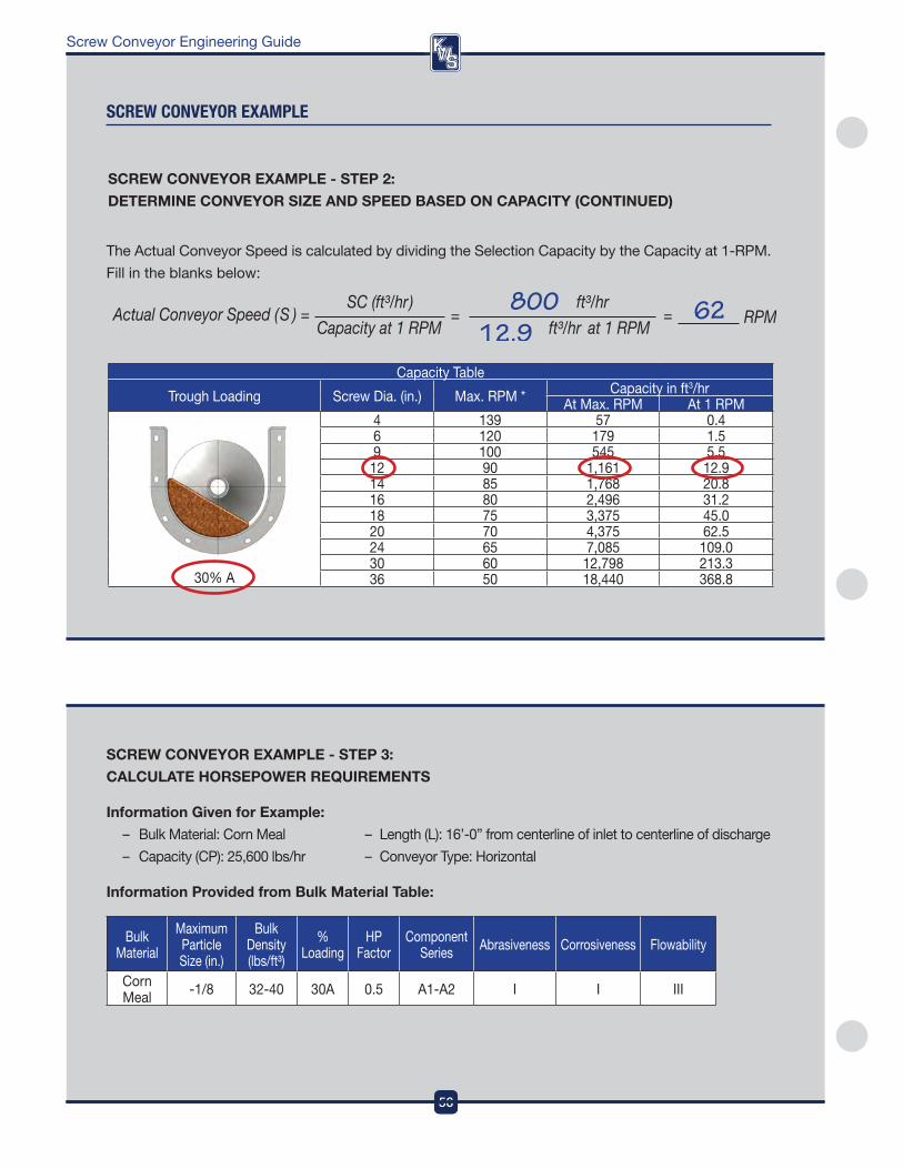
DesignEngineeringManufacturing
56
Screw Conveyor Engineering Guide
sCReW COnVeYOR eXaMPle
SCREW CoNVEYoR ExAMplE - STEp 3:
CAlCUlATE HoRSEpoWER REQUIREMENTS
Information Given for Example:
– Bulk Material: Corn Meal – Length (L): 16’-0” from centerline of inlet to centerline of discharge
– Capacity (Cp): 25,600 lbs/hr – Conveyor Type: Horizontal
Information provided from Bulk Material Table:
Bulk Material
Maximum particle Size (in .)
Bulk density (lbs/ft³)
% Loading
Hp factor
Component Series abrasiveness Corrosiveness flowability
Corn Meal -1/8 32-40 30a 0 .5 a1-a2 i i iii
Capacity Table
Trough Loading Screw dia . (in .) Max . rpM * Capacity in ft3/hr at Max . rpM at 1 rpM
30% a
4 139 57 0 .46 120 179 1 .59 100 545 5 .5
12 90 1,161 12 .914 85 1,768 20 .816 80 2,496 31 .218 75 3,375 45 .020 70 4,375 62 .524 65 7,085 109 .030 60 12,798 213 .336 50 18,440 368 .8
The actual Conveyor Speed is calculated by dividing the Selection Capacity by the Capacity at 1-rpM .
fill in the blanks below:
SCREW CoNVEYoR ExAMplE - STEp 2:
DETERMINE CoNVEYoR SIZE AND SpEED BASED oN CApACITY (CoNTINUED)
56
DesignEngineeringManufacturing
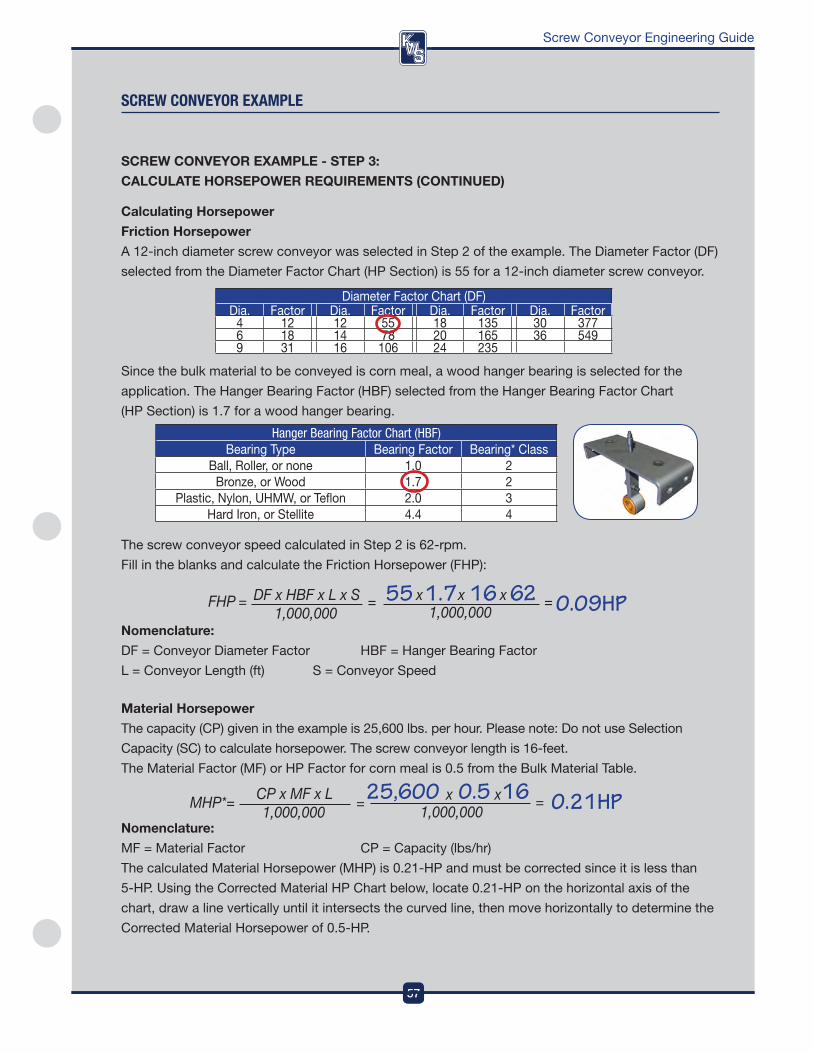
57
DesignEngineeringManufacturing
Screw Conveyor Engineering Guide
sCReW COnVeYOR eXaMPle
The screw conveyor speed calculated in Step 2 is 62-rpm .
fill in the blanks and calculate the friction Horsepower (fHp):
Nomenclature:
df = Conveyor diameter factor HBf = Hanger Bearing factor
L = Conveyor Length (ft) S = Conveyor Speed
Material Horsepower
The capacity (Cp) given in the example is 25,600 lbs . per hour . please note: do not use Selection
Capacity (SC) to calculate horsepower . The screw conveyor length is 16-feet .
The Material factor (Mf) or Hp factor for corn meal is 0 .5 from the Bulk Material Table .
Nomenclature:
Mf = Material factor Cp = Capacity (lbs/hr)
The calculated Material Horsepower (MHp) is 0 .21-Hp and must be corrected since it is less than
5-Hp . Using the Corrected Material Hp Chart below, locate 0 .21-Hp on the horizontal axis of the
chart, draw a line vertically until it intersects the curved line, then move horizontally to determine the
Corrected Material Horsepower of 0 .5-Hp .
SCREW CoNVEYoR ExAMplE - STEp 3:
CAlCUlATE HoRSEpoWER REQUIREMENTS (CoNTINUED)
diameter factor Chart (df)dia . factor dia . factor dia . factor dia . factor
4 12 12 55 18 135 30 3776 18 14 78 20 165 36 5499 31 16 106 24 235
Calculating Horsepower
friction Horsepower
a 12-inch diameter screw conveyor was selected in Step 2 of the example . The diameter factor (df)
selected from the diameter factor Chart (Hp Section) is 55 for a 12-inch diameter screw conveyor .
Since the bulk material to be conveyed is corn meal, a wood hanger bearing is selected for the
application . The Hanger Bearing factor (HBf) selected from the Hanger Bearing factor Chart
(Hp Section) is 1 .7 for a wood hanger bearing .
Hanger Bearing Factor Chart (HBF)Bearing Type Bearing factor Bearing* Class
Ball, roller, or none 1 .0 2Bronze, or wood 1 .7 2
plastic, nylon, UHMw, or Teflon 2 .0 3Hard iron, or Stellite 4 .4 4
57
DesignEngineeringManufacturing
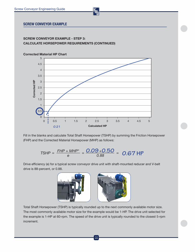
DesignEngineeringManufacturing
58
Screw Conveyor Engineering Guide
fill in the blanks and calculate Total Shaft Horsepower (TSHp) by summing the friction Horsepower
(fHp) and the Corrected Material Horsepower (MHp) as follows:
drive efficiency (e) for a typical screw conveyor drive unit with shaft-mounted reducer and v-belt
drive is 88-percent, or 0 .88 .
Total Shaft Horsepower (TSHp) is typically rounded up to the next commonly available motor size .
The most commonly available motor size for the example would be 1-Hp . The drive unit selected for
the example is 1-Hp at 60-rpm . The speed of the drive unit is typically rounded to the closest 5-rpm
increment .
sCReW COnVeYOR eXaMPle
Calculated HP
0 0.5 1 1.5 2 2.5 3 3.5 4 4.5 5
Cor
rect
ed H
P
5
4.5
4
3.5
3
2.5
2
1.5
1
0.5
0
Corrected Material Hp Chart
0.21
SCREW CoNVEYoR ExAMplE - STEp 3:
CAlCUlATE HoRSEpoWER REQUIREMENTS (CoNTINUED)
58
DesignEngineeringManufacturing
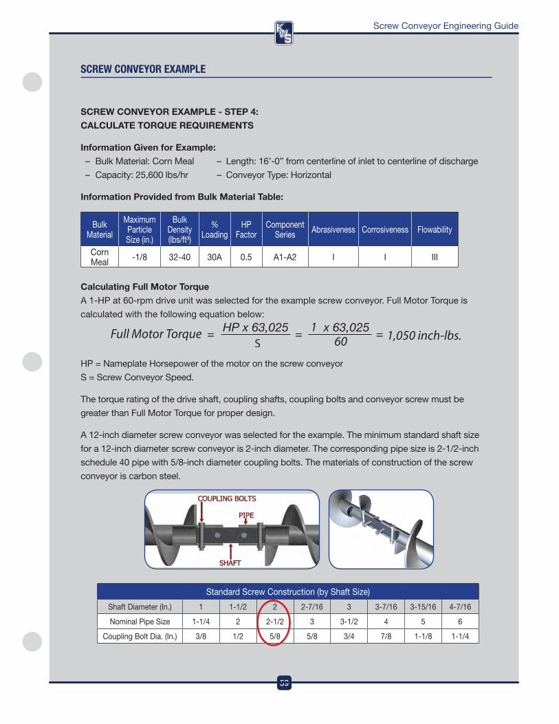
59
DesignEngineeringManufacturing
Screw Conveyor Engineering Guide
59
DesignEngineeringManufacturing
SCREW CoNVEYoR ExAMplE - STEp 4:
CAlCUlATE ToRQUE REQUIREMENTS
Information Given for Example:
– Bulk Material: Corn Meal – Length: 16’-0” from centerline of inlet to centerline of discharge
– Capacity: 25,600 lbs/hr – Conveyor Type: Horizontal
Information provided from Bulk Material Table:
Bulk Material
Maximum particle Size (in .)
Bulk density (lbs/ft³)
% Loading
Hp factor
Component Series abrasiveness Corrosiveness flowability
Corn Meal -1/8 32-40 30a 0 .5 a1-a2 i i iii
Calculating full Motor Torque
a 1-Hp at 60-rpm drive unit was selected for the example screw conveyor . full Motor Torque is
calculated with the following equation below:
Hp = nameplate Horsepower of the motor on the screw conveyor
S = Screw Conveyor Speed .
The torque rating of the drive shaft, coupling shafts, coupling bolts and conveyor screw must be
greater than full Motor Torque for proper design .
a 12-inch diameter screw conveyor was selected for the example . The minimum standard shaft size
for a 12-inch diameter screw conveyor is 2-inch diameter . The corresponding pipe size is 2-1/2-inch
schedule 40 pipe with 5/8-inch diameter coupling bolts . The materials of construction of the screw
conveyor is carbon steel .
Standard Screw Construction (by Shaft Size)
Shaft diameter (in .) 1 1-1/2 2 2-7/16 3 3-7/16 3-15/16 4-7/16
nominal pipe Size 1-1/4 2 2-1/2 3 3-1/2 4 5 6
Coupling Bolt dia . (in .) 3/8 1/2 5/8 5/8 3/4 7/8 1-1/8 1-1/4
sCReW COnVeYOR eXaMPle
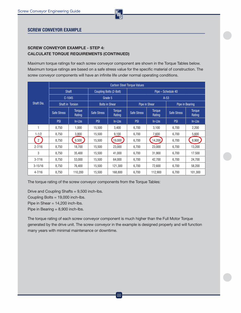
DesignEngineeringManufacturing
60
Screw Conveyor Engineering Guide
SCREW CoNVEYoR ExAMplE - STEp 4:
CAlCUlATE ToRQUE REQUIREMENTS (CoNTINUED)
Maximum torque ratings for each screw conveyor component are shown in the Torque Tables below .
Maximum torque ratings are based on a safe stress value for the specific material of construction . The
screw conveyor components will have an infinite life under normal operating conditions .
Shaft Dia.
Carbon Steel Torque Values
Shaft Coupling Bolts (2-Bolt) Pipe – Schedule 40
C-1045 Grade 5 A-53
Shaft in Torsion Bolts in Shear Pipe in Shear Pipe in Bearing
Safe StressTorque Rating
Safe StressTorque Rating
Safe StressTorque Rating
Safe StressTorque Rating
PSI In-Lbs PSI In-Lbs PSI In-Lbs PSI In-Lbs
1 8,750 1,000 15,500 3,400 6,700 3,100 6,700 2,200
1-1/2 8,750 3,800 15,500 9,100 6,700 7,600 6,700 5,600
2 8,750 9,500 15,500 19,000 6,700 14,200 6,700 8,900
2-7/16 8,750 18,700 15,500 23,000 6,700 23,000 6,700 13,200
3 8,750 35,400 15,500 41,000 6,700 31,900 6,700 17.500
3-7/16 8,750 53,000 15,500 64,000 6,700 42,700 6,700 24,700
3-15/16 8,750 76,400 15,500 121,300 6,700 72,600 6,700 58,200
4-7/16 8,750 110,200 15,500 168,800 6,700 112,900 6,700 101,300
The torque rating of the screw conveyor components from the Torque Tables:
drive and Coupling Shafts = 9,500 inch-lbs .
Coupling Bolts = 19,000 inch-lbs .
pipe in Shear = 14,200 inch-lbs .
pipe in Bearing = 8,900 inch-lbs .
The torque rating of each screw conveyor component is much higher than the full Motor Torque
generated by the drive unit . The screw conveyor in the example is designed properly and will function
many years with minimal maintenance or downtime .
sCReW COnVeYOR eXaMPle
60
DesignEngineeringManufacturing
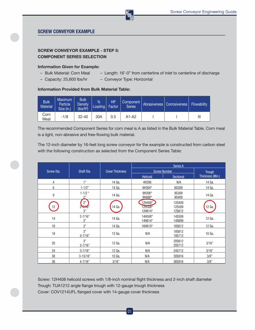
61
DesignEngineeringManufacturing
Screw Conveyor Engineering Guide
SCREW CoNVEYoR ExAMplE - STEp 5:
CoMpoNENT SERIES SElECTIoN
Information Given for Example:
– Bulk Material: Corn Meal – Length: 16’-0” from centerline of inlet to centerline of discharge
– Capacity: 25,600 lbs/hr – Conveyor Type: Horizontal
Information provided from Bulk Material Table:
Bulk Material
Maximum particle Size (in .)
Bulk density (lbs/ft³)
% Loading
Hp factor
Component Series abrasiveness Corrosiveness flowability
Corn Meal -1/8 32-40 30a 0 .5 a1-a2 i i iii
The recommended Component Series for corn meal is a as listed in the Bulk Material Table . Corn meal
is a light, non-abrasive and free-flowing bulk material .
The 12-inch diameter by 16-feet long screw conveyor for the example is constructed from carbon steel
with the following construction as selected from the Component Series Table:
sCReW COnVeYOR eXaMPle
Screw Dia. Shaft Dia. Cover Thickness
Series A
Screw Number Trough Thickness (Min.)Helicoid Sectional
4 1” 14 Ga. 4H206 N/A 14 Ga.
6 1-1/2” 14 Ga. 6H304* 6S309 14 Ga.
9 1-1/2 “ 2” 14 Ga. 9H306*
9H406*9S309 9S409 14 Ga.
122”
2-7/16” 3”
14 Ga.12H408* 12H508* 12H614*
12S409 12S509 12S612
12 Ga.
14 2-7/16” 3” 14 Ga. 14H508*
14H614*14S509 14S609 12 Ga.
16 3” 14 Ga. 16H610* 16S612 12 Ga.
18 3” 3-7/16” 12 Ga. N/A 18S612
18S712 10 Ga.
20 3” 3-7/16” 12 Ga. N/A 20S612
20S712 3/16”
24 3-7/16” 12 Ga. N/A 24S712 3/16”
30 3-15/16” 10 Ga. N/A 30S816 3/8”
36 4-7/16” 3/16” N/A 36S916 3/8”
Screw: 12H408 helicoid screws with 1/8-inch nominal flight thickness and 2-inch shaft diameter
Trough: TUa1212 angle flange trough with 12-gauge trough thickness
Cover: Cov1214UfL flanged cover with 14-gauge cover thickness
61
DesignEngineeringManufacturing
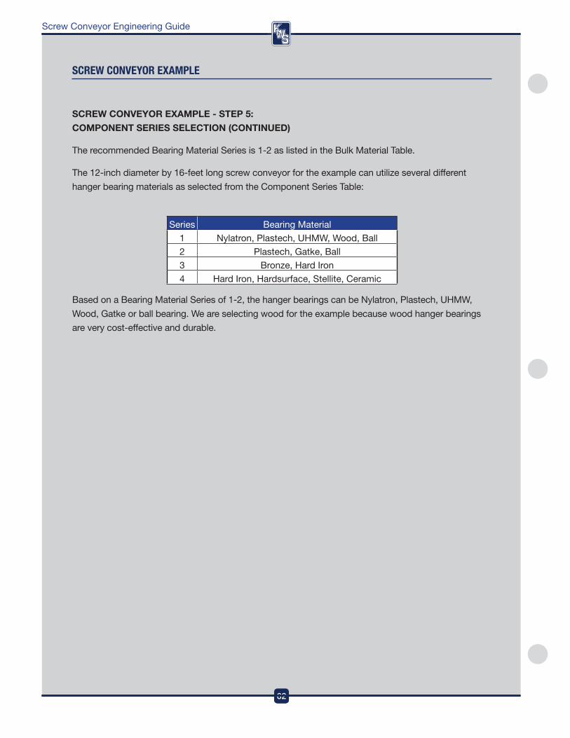
DesignEngineeringManufacturing
62
Screw Conveyor Engineering Guide
62
DesignEngineeringManufacturing
sCReW COnVeYOR eXaMPle
SCREW CoNVEYoR ExAMplE - STEp 5:
CoMpoNENT SERIES SElECTIoN (CoNTINUED)
The recommended Bearing Material Series is 1-2 as listed in the Bulk Material Table .
The 12-inch diameter by 16-feet long screw conveyor for the example can utilize several different
hanger bearing materials as selected from the Component Series Table:
Series Bearing Material
1 nylatron, plastech, UHMw, wood, Ball
2 plastech, Gatke, Ball
3 Bronze, Hard iron
4 Hard iron, Hardsurface, Stellite, Ceramic
Based on a Bearing Material Series of 1-2, the hanger bearings can be nylatron, plastech, UHMw,
wood, Gatke or ball bearing . we are selecting wood for the example because wood hanger bearings
are very cost-effective and durable .
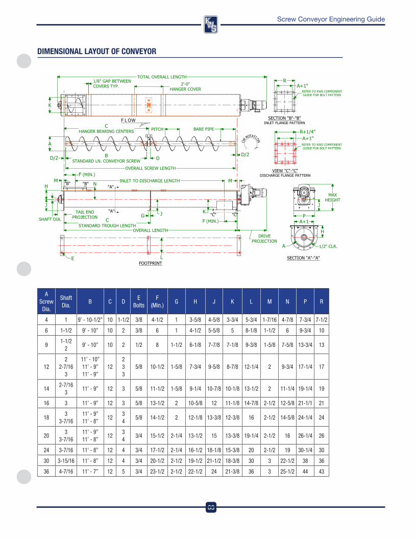
63
DesignEngineeringManufacturing
Screw Conveyor Engineering Guide
DIMensIOnal laYOUT Of COnVeYOR
A Screw Dia.
Shaft Dia.
B C DE
BoltsF
(Min.)G H J K L M N P R
4 1 9’ - 10-1/2” 10 1-1/2 3/8 4-1/2 1 3-5/8 4-5/8 3-3/4 5-3/4 1-7/16 4-7/8 7-3/4 7-1/2
6 1-1/2 9’ - 10” 10 2 3/8 6 1 4-1/2 5-5/8 5 8-1/8 1-1/2 6 9-3/4 10
91-1/2
29’ - 10” 10 2 1/2 8 1-1/2 6-1/8 7-7/8 7-1/8 9-3/8 1-5/8 7-5/8 13-3/4 13
122
2-7/16 3
11’ - 10” 11’ - 9” 11’ - 9”
122 3 3
5/8 10-1/2 1-5/8 7-3/4 9-5/8 8-7/8 12-1/4 2 9-3/4 17-1/4 17
142-7/16
311’ - 9” 12 3 5/8 11-1/2 1-5/8 9-1/4 10-7/8 10-1/8 13-1/2 2 11-1/4 19-1/4 19
16 3 11’ - 9” 12 3 5/8 13-1/2 2 10-5/8 12 11-1/8 14-7/8 2-1/2 12-5/8 21-1/1 21
183
3-7/1611’ - 9” 11’ - 8”
123 4
5/8 14-1/2 2 12-1/8 13-3/8 12-3/8 16 2-1/2 14-5/8 24-1/4 24
203
3-7/1611’ - 9” 11’ - 8”
123 4
3/4 15-1/2 2-1/4 13-1/2 15 13-3/8 19-1/4 2-1/2 16 26-1/4 26
24 3-7/16 11’ - 8” 12 4 3/4 17-1/2 2-1/4 16-1/2 18-1/8 15-3/8 20 2-1/2 19 30-1/4 30
30 3-15/16 11’ - 8” 12 4 3/4 20-1/2 2-1/2 19-1/2 21-1/2 18-3/8 30 3 22-1/2 38 36
36 4-7/16 11’ - 7” 12 5 3/4 23-1/2 2-1/2 22-1/2 24 21-3/8 36 3 25-1/2 44 43

DesignEngineeringManufacturing
64
Screw Conveyor Engineering Guide
Notes

65
DesignEngineeringManufacturing
Screw Conveyor Engineering Guide
Notes
DesignEngineeringManufacturing
3041 Conveyor Drive | Burleson, TX 76028Toll-free: (800) 543-6558 | Local Phone: (817) 295-2240 | Fax: (817) 447-8528
Inquiries: [email protected] | www.kwsmfg.com
MADE IN THE USA
ISO 9001Certified
Conveying Knowledge, Workmanship, Solutions
What makes KWS different from other manufacturers?At KWS we understand the needs and exceed the expectations of our Customers. As an ISO-9001 certified company, quality is integrated into every aspect of our processes. Quality is defined by the Customer, and derived from the total KWS Customer experience. It’s not just product quality, but quality throughout every step of the Sales, Engineering and Manufacturing processes. Quality starts with our first Customer contact and never ends.
© Copyright 2015, KWS Manufacturing, Ltd. 100115
Recommended