ENSC 427: COMMUNICATION NETWORKS
EVALUATION OF GAMING TRAFFIC OVER WIMAX
SPRING 2010 FINAL PROJECT
Group #3
Kelvin Ho – [email protected]
Titus Cheung – [email protected]
Glen Nogayev – [email protected]
URL: www.sfu.ca/~kkh2/ensc427
Table of Contents
1. Abstract .............................................................................................................................................................................. 6
2. Introduction ..................................................................................................................................................................... 7
2.1 Background and Motivation ............................................................................................................................ 7
2.1 Project Goals ........................................................................................................................................................... 8
3. Gaming Traffic Design .................................................................................................................................................. 9
4. Simulation Design ........................................................................................................................................................ 10
4.1 Network Topologies .......................................................................................................................................... 10
4.2 WiMAX Configuration ....................................................................................................................................... 11
4.3 Gaming Traffic Model ....................................................................................................................................... 13
5. Expected Results .......................................................................................................................................................... 16
6. Simulation Results ....................................................................................................................................................... 16
6.1 Throughput ........................................................................................................................................................... 16
6.2 End to End Delay (Uplink and Downlink) ................................................................................................ 18
6.3 Packet Loss............................................................................................................................................................ 20
6.4 Jitter ......................................................................................................................................................................... 21
6.5 Simulation Summary ........................................................................................................................................ 21
7. Conclusion and Future Work .................................................................................................................................. 22
7.1 Conclusion ............................................................................................................................................................. 22
7.2 Future Work ......................................................................................................................................................... 22
8. References ....................................................................................................................................................................... 23
9. Appendix A ..................................................................................................................................................................... 24
List of Figures Figure 1 – Worldwide Deployment of WiMAX ............................................................................................................ 7
Figure 2 – 1 Client setup to verify gaming traffic ..................................................................................................... 10
Figure 3 – 3 Client setup ..................................................................................................................................................... 10
Figure 4 – 2 Client setup. .................................................................................................................................................... 10
Figure 5 – 5 Client setup ..................................................................................................................................................... 11
Figure 6 – WiMAX Configuration .................................................................................................................................... 12
Figure 7 – Base Station and User Node Configuration ........................................................................................... 12
Figure 9 – Downlink and Uplink Service Flows ........................................................................................................ 13
Figure 10 – Custom Application Parameters ............................................................................................................. 13
Figure 11 – Task Description ............................................................................................................................................ 14
Figure 12 – Profile Attributes ........................................................................................................................................... 14
Figure 13 – Task Manual Configuration ....................................................................................................................... 14
Figure 14 – Client-Server Traffic Settings ................................................................................................................... 15
Figure 15 – User Supported Profiles.............................................................................................................................. 15
Figure 16 – Game Server Supported Services ............................................................................................................ 16
Figure 17 – 1 Client scenario: Throughput (Uplink and Downlink) ................................................................. 17
Figure 18 – 3 Client scenario: Throughput (Downlink) ........................................................................................ 17
Figure 19 – Client scenario: Throughput (Uplink)................................................................................................... 17
Figure 20 – 5 Client scenario: Throughput (Downlink) ........................................................................................ 17
Figure 21 – 5 Client scenario: Throughput (Uplink) ............................................................................................... 17
Figure 22 – 2 Client scenario: Throughput (Downlink) ........................................................................................ 18
Figure 23 – 2 Client scenario: Throughput (Uplink) ............................................................................................... 18
Figure 24 – 1 Client scenario: Delay (Uplink and Downlink) .............................................................................. 18
Figure 25 – 3 Client scenario: Delay (Downlink)...................................................................................................... 19
Figure 26 – 3 Client scenario: Delay (Uplink) ............................................................................................................ 19
Figure 27 – 5 Client scenario: Delay (Downlink)...................................................................................................... 19
Figure 28 – 5 Client scenario: Delay (Uplink) ............................................................................................................ 19
Figure 29 – 2 Client scenario: Delay (Downlink)...................................................................................................... 19
Figure 30 – 2 Client scenario: Delay (Uplink) ............................................................................................................ 19
Figure 31 – 1 Client Scenario: Packet Loss .................................................................................................................. 20
Figure 32 – 3 Client Scenario: Packet Loss (Downlink) ......................................................................................... 20
Figure 33 – 3 Client Scenario: Packet Loss (Uplink) ............................................................................................... 20
Figure 34 – 5 Client Scenario: Packet Loss (Uplink) ............................................................................................... 20
Figure 35 – 2 Client Scenario: Packet Loss (Uplink) ............................................................................................... 21
Figure 36 - PDF of server packet interarrival time per client ............................................................................. 24
Figure 37 – Complementary CDF of server packet interarrival time per client .......................................... 24
Figure 38 – PDF of server packet size per client ...................................................................................................... 24
Figure 39 – Complementary CDF of server packet size per client .................................................................... 24
Figure 40 – PDF of client packet interarrival time per client [1] ....................................................................... 25
Figure 41 – Complementary CDF of client packet interarrival time per client [1] ..................................... 25

List of Tables Table 1 - WiMAX Application Classes [3]....................................................................................................................... 8
Table 2 - One way game delay requirements ............................................................................................................... 9
Table 3- Counter Strike traffic characteristics and approximations .................................................................. 9
Table 4 - Global Consumer Internet Gaming Traffic, 2008-2013 ...................................................................... 24
List of Acronyms dBi – Decibel Isotropic
DSL – Digital Subscriber Loop
FPS – First Person Shooter
Kbps – Kilobits per second
MAC – Machine Address Code
QAM – Quadrature amplitude modulation
QoE – Quality of Experience
QoS – Quality of Service
RPG – Role Playing Game
RTS – Real Time Strategy
SAP – Service Access Point
SNR – Signal-to-Noise Ratio
WiFi – Wireless Fidelity
WiMAX – Worldwide Interoperability for Microwave Access
1. ABSTRACT
The goal of this project is to simulate online gaming traffic over a Worldwide Interoperability for
Microwave Access (WiMAX) network. Over the past couple of years, WiMAX has been gaining
popularity as an IP-based wireless access network due to its suitability for mobile users compared
to Wireless Local Area Network (WLAN) technology. Since then, a high quality of service for both
the video and audio signals is essential for online gaming, the project will focus on measuring
quantities such as delay and jitter, latency and bandwidth consumption for various online gaming
traffic loads. We will use OPNET Modeler 14.0 as the simulation tool for this project.
2. INTRODUCTION 2.1 Background and Motivation
The internet is becoming more ubiquitous and more available to people and the demand and usage
for entertainment is constantly increasing as well. According to [1], gaming traffic on any major
traffic backbone consist of 4%-5%. According to Cisco’s Virtual Networking Index, gaming traffic is
expected to continue growing at an average rate of 39% over the next 3 years as shown in Appendix
A [2]. As per Cisco’s definition, gaming includes casual online gaming, networked console gaming,
and multiplayer virtual world gaming.
Older forms of connectivity to the internet required a physical connection – whether it be a cable or
a digital subscriber loop (DSL). Unfortunately, this meant that many remote locations or
inaccessible locations will not be able to have connectivity to the internet. Technology, however,
has bridged the gap and now a solution exists for providing internet to these locations – Worldwide
Interoperability for Microwave Access (WiMAX) is one of the suitable wireless solutions.
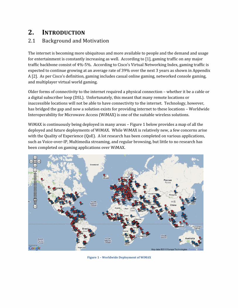
WiMAX is continuously being deployed in many areas – Figure 1 below provides a map of all the
deployed and future deployments of WiMAX. While WiMAX is relatively new, a few concerns arise
with the Quality of Experience (QoE). A lot research has been completed on various applications,
such as Voice-over-IP, Multimedia streaming, and regular browsing, but little to no research has
been completed on gaming applications over WiMAX.
Figure 1 – Worldwide Deployment of WiMAX
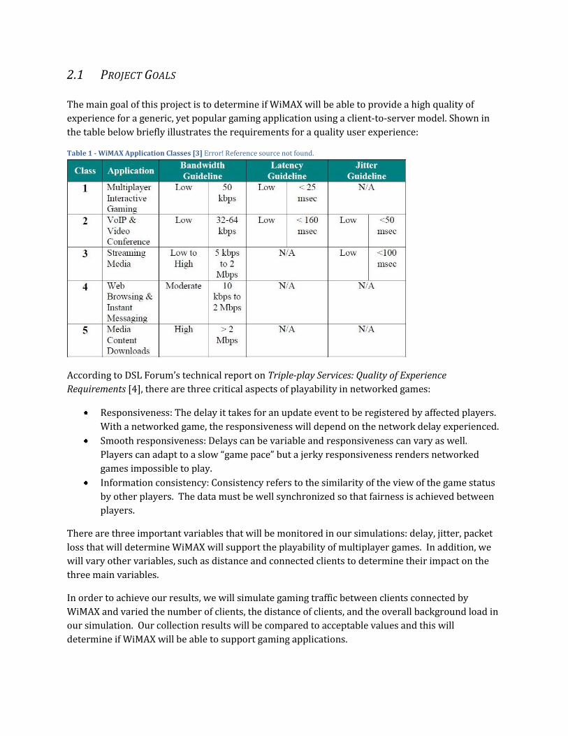
2.1 PROJECT GOALS
The main goal of this project is to determine if WiMAX will be able to provide a high quality of
experience for a generic, yet popular gaming application using a client-to-server model. Shown in
the table below briefly illustrates the requirements for a quality user experience:
Table 1 - WiMAX Application Classes [3] Error! Reference source not found.
According to DSL Forum’s technical report on Triple-play Services: Quality of Experience
Requirements [4], there are three critical aspects of playability in networked games:
Responsiveness: The delay it takes for an update event to be registered by affected players.
With a networked game, the responsiveness will depend on the network delay experienced.
Smooth responsiveness: Delays can be variable and responsiveness can vary as well.
Players can adapt to a slow “game pace” but a jerky responsiveness renders networked
games impossible to play.
Information consistency: Consistency refers to the similarity of the view of the game status
by other players. The data must be well synchronized so that fairness is achieved between
players.
There are three important variables that will be monitored in our simulations: delay, jitter, packet
loss that will determine WiMAX will support the playability of multiplayer games. In addition, we
will vary other variables, such as distance and connected clients to determine their impact on the
three main variables.
In order to achieve our results, we will simulate gaming traffic between clients connected by
WiMAX and varied the number of clients, the distance of clients, and the overall background load in
our simulation. Our collection results will be compared to acceptable values and this will
determine if WiMAX will be able to support gaming applications.
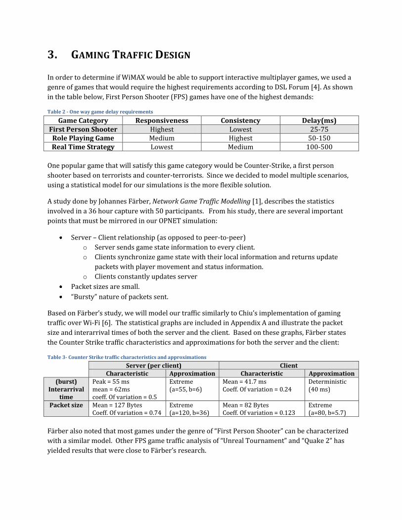
3. GAMING TRAFFIC DESIGN
In order to determine if WiMAX would be able to support interactive multiplayer games, we used a
genre of games that would require the highest requirements according to DSL Forum [4]. As shown
in the table below, First Person Shooter (FPS) games have one of the highest demands:
Table 2 - One way game delay requirements
Game Category Responsiveness Consistency Delay(ms) First Person Shooter Highest Lowest 25-75
Role Playing Game Medium Highest 50-150 Real Time Strategy Lowest Medium 100-500
One popular game that will satisfy this game category would be Counter-Strike, a first person
shooter based on terrorists and counter-terrorists. Since we decided to model multiple scenarios,
using a statistical model for our simulations is the more flexible solution.
A study done by Johannes Färber, Network Game Traffic Modelling [1], describes the statistics
involved in a 36 hour capture with 50 participants. From his study, there are several important
points that must be mirrored in our OPNET simulation:
Server – Client relationship (as opposed to peer-to-peer)
o Server sends game state information to every client.
o Clients synchronize game state with their local information and returns update
packets with player movement and status information.
o Clients constantly updates server
Packet sizes are small.
“Bursty” nature of packets sent.
Based on Färber’s study, we will model our traffic similarly to Chiu’s implementation of gaming
traffic over Wi-Fi [6]. The statistical graphs are included in Appendix A and illustrate the packet
size and interarrival times of both the server and the client. Based on these graphs, Färber states
the Counter Strike traffic characteristics and approximations for both the server and the client:
Table 3- Counter Strike traffic characteristics and approximations
Server (per client) Client Characteristic Approximation Characteristic Approximation
(burst) Interarrival
time
Peak = 55 ms mean = 62ms coeff. Of variation = 0.5
Extreme (a=55, b=6)
Mean = 41.7 ms Coeff. Of variation = 0.24
Deterministic (40 ms)
Packet size Mean = 127 Bytes Coeff. Of variation = 0.74
Extreme (a=120, b=36)
Mean = 82 Bytes Coeff. Of variation = 0.123
Extreme (a=80, b=5.7)
Färber also noted that most games under the genre of “First Person Shooter” can be characterized
with a similar model. Other FPS game traffic analysis of “Unreal Tournament” and “Quake 2” has
yielded results that were close to Färber’s research.
4. SIMULATION DESIGN
In our project, we used OPNET Modeler 14.0 to simulate 4 different network topologies, as
categorized in the following section. We used the WiMAX model and the corresponding object
palette that is provided with OPNET. As mentioned above, all scenarios use an approximated
statistical model for the game traffic for Counter Strike.
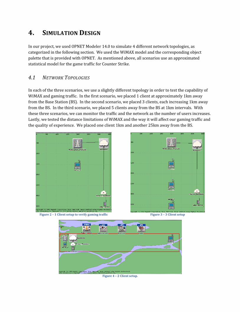
4.1 NETWORK TOPOLOGIES
In each of the three scenarios, we use a slightly different topology in order to test the capability of
WiMAX and gaming traffic. In the first scenario, we placed 1 client at approximately 1km away
from the Base Station (BS). In the second scenario, we placed 3 clients, each increasing 1km away
from the BS. In the third scenario, we placed 5 clients away from the BS at 1km intervals. With
these three scenarios, we can monitor the traffic and the network as the number of users increases.
Lastly, we tested the distance limitations of WiMAX and the way it will affect our gaming traffic and
the quality of experience. We placed one client 1km and another 25km away from the BS.
Figure 2 – 1 Client setup to verify gaming traffic
Figure 3 – 3 Client setup
Figure 4 – 2 Client setup.
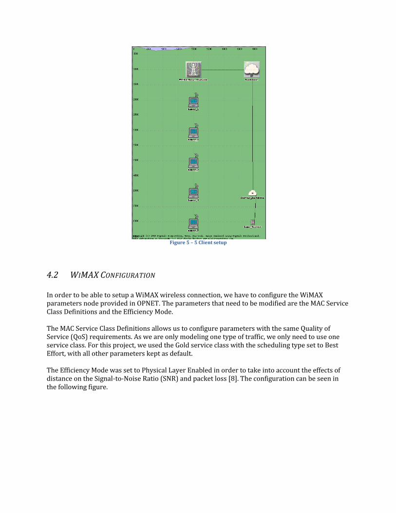
Figure 5 – 5 Client setup
4.2 WIMAX CONFIGURATION
In order to be able to setup a WiMAX wireless connection, we have to configure the WiMAX parameters node provided in OPNET. The parameters that need to be modified are the MAC Service Class Definitions and the Efficiency Mode. The MAC Service Class Definitions allows us to configure parameters with the same Quality of Service (QoS) requirements. As we are only modeling one type of traffic, we only need to use one service class. For this project, we used the Gold service class with the scheduling type set to Best Effort, with all other parameters kept as default. The Efficiency Mode was set to Physical Layer Enabled in order to take into account the effects of distance on the Signal-to-Noise Ratio (SNR) and packet loss [8]. The configuration can be seen in the following figure.
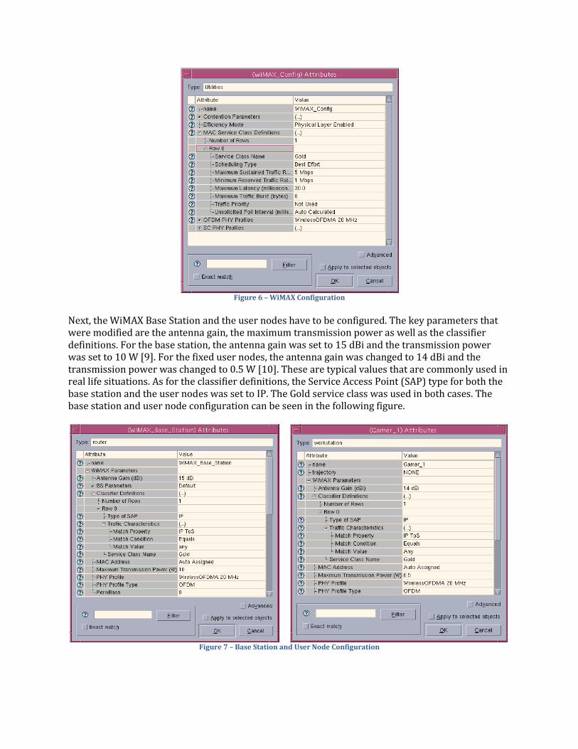
Figure 6 – WiMAX Configuration
Next, the WiMAX Base Station and the user nodes have to be configured. The key parameters that were modified are the antenna gain, the maximum transmission power as well as the classifier definitions. For the base station, the antenna gain was set to 15 dBi and the transmission power was set to 10 W [9]. For the fixed user nodes, the antenna gain was changed to 14 dBi and the transmission power was changed to 0.5 W [10]. These are typical values that are commonly used in real life situations. As for the classifier definitions, the Service Access Point (SAP) type for both the base station and the user nodes was set to IP. The Gold service class was used in both cases. The base station and user node configuration can be seen in the following figure.
Figure 7 – Base Station and User Node Configuration
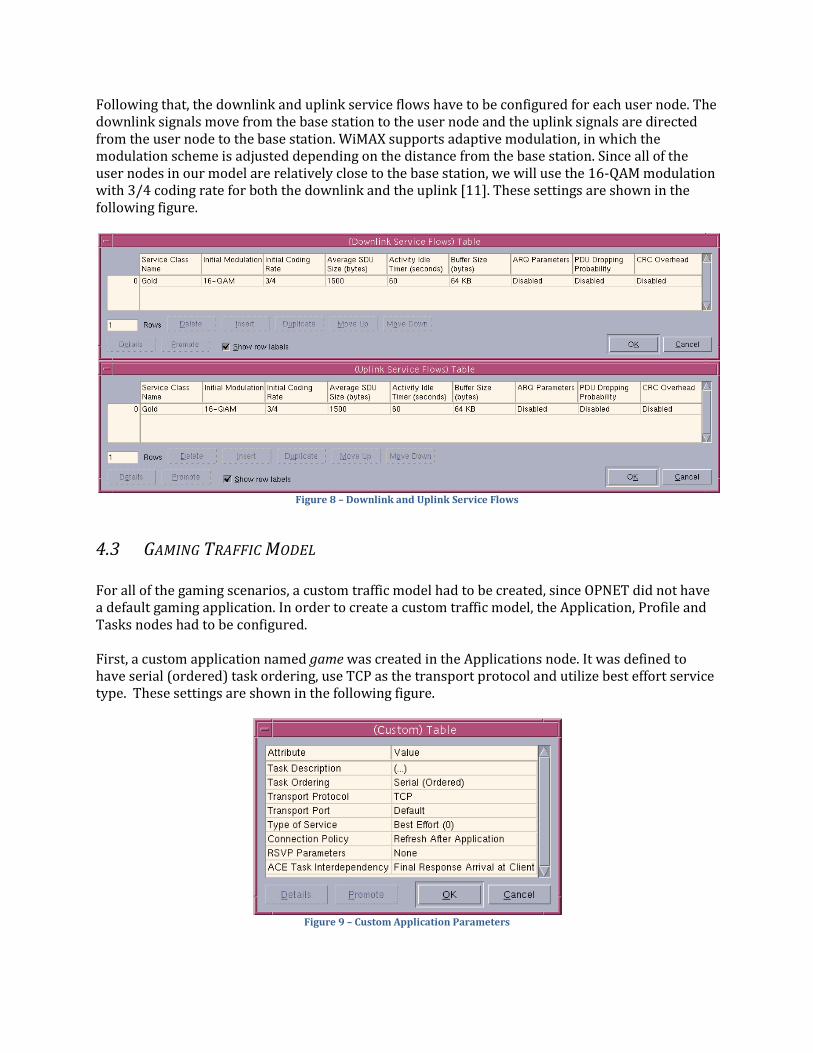
Following that, the downlink and uplink service flows have to be configured for each user node. The downlink signals move from the base station to the user node and the uplink signals are directed from the user node to the base station. WiMAX supports adaptive modulation, in which the modulation scheme is adjusted depending on the distance from the base station. Since all of the user nodes in our model are relatively close to the base station, we will use the 16-QAM modulation with 3/4 coding rate for both the downlink and the uplink [11]. These settings are shown in the following figure.
Figure 8 – Downlink and Uplink Service Flows
4.3 GAMING TRAFFIC MODEL
For all of the gaming scenarios, a custom traffic model had to be created, since OPNET did not have a default gaming application. In order to create a custom traffic model, the Application, Profile and Tasks nodes had to be configured. First, a custom application named game was created in the Applications node. It was defined to have serial (ordered) task ordering, use TCP as the transport protocol and utilize best effort service type. These settings are shown in the following figure.
Figure 9 – Custom Application Parameters
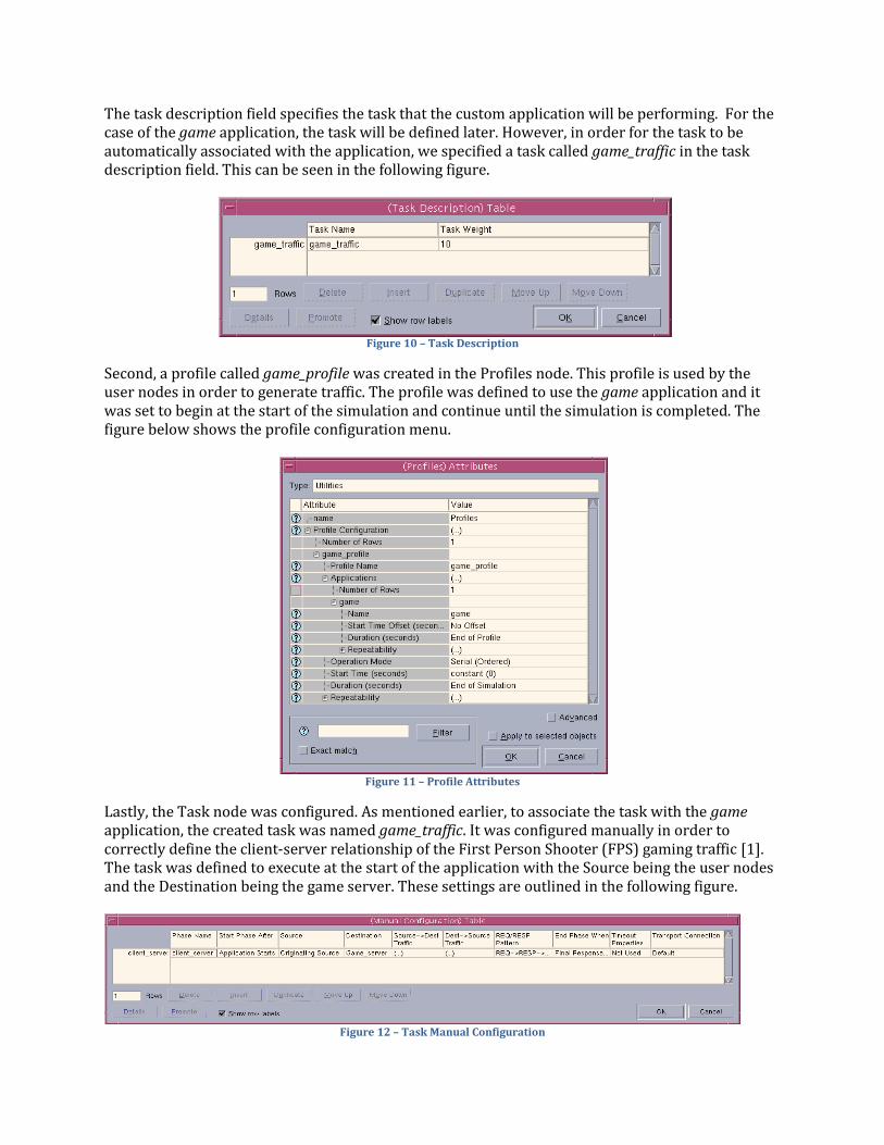
The task description field specifies the task that the custom application will be performing. For the case of the game application, the task will be defined later. However, in order for the task to be automatically associated with the application, we specified a task called game_traffic in the task description field. This can be seen in the following figure.
Figure 10 – Task Description
Second, a profile called game_profile was created in the Profiles node. This profile is used by the user nodes in order to generate traffic. The profile was defined to use the game application and it was set to begin at the start of the simulation and continue until the simulation is completed. The figure below shows the profile configuration menu.
Figure 11 – Profile Attributes
Lastly, the Task node was configured. As mentioned earlier, to associate the task with the game application, the created task was named game_traffic. It was configured manually in order to correctly define the client-server relationship of the First Person Shooter (FPS) gaming traffic [1]. The task was defined to execute at the start of the application with the Source being the user nodes and the Destination being the game server. These settings are outlined in the following figure.
Figure 12 – Task Manual Configuration
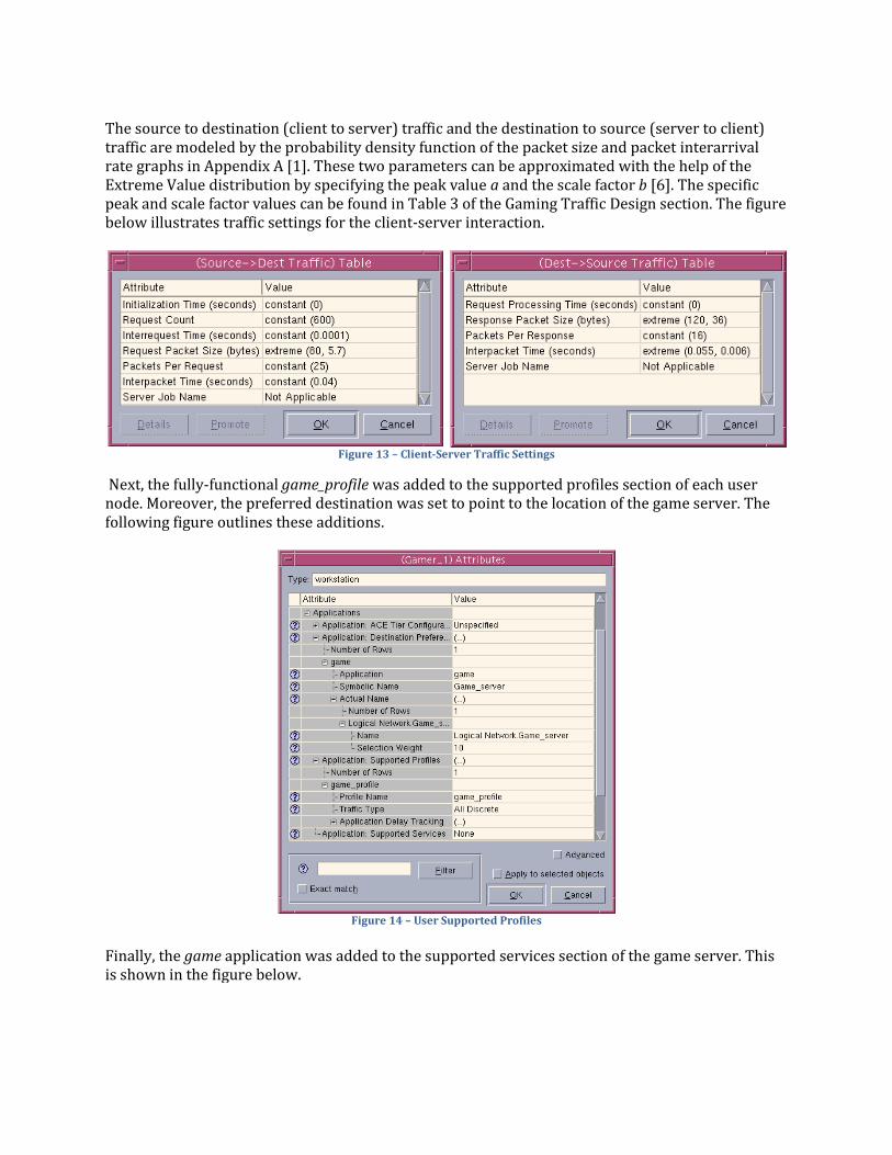
The source to destination (client to server) traffic and the destination to source (server to client) traffic are modeled by the probability density function of the packet size and packet interarrival rate graphs in Appendix A [1]. These two parameters can be approximated with the help of the Extreme Value distribution by specifying the peak value a and the scale factor b [6]. The specific peak and scale factor values can be found in Table 3 of the Gaming Traffic Design section. The figure below illustrates traffic settings for the client-server interaction.
Figure 13 – Client-Server Traffic Settings
Next, the fully-functional game_profile was added to the supported profiles section of each user node. Moreover, the preferred destination was set to point to the location of the game server. The following figure outlines these additions.
Figure 14 – User Supported Profiles
Finally, the game application was added to the supported services section of the game server. This is shown in the figure below.
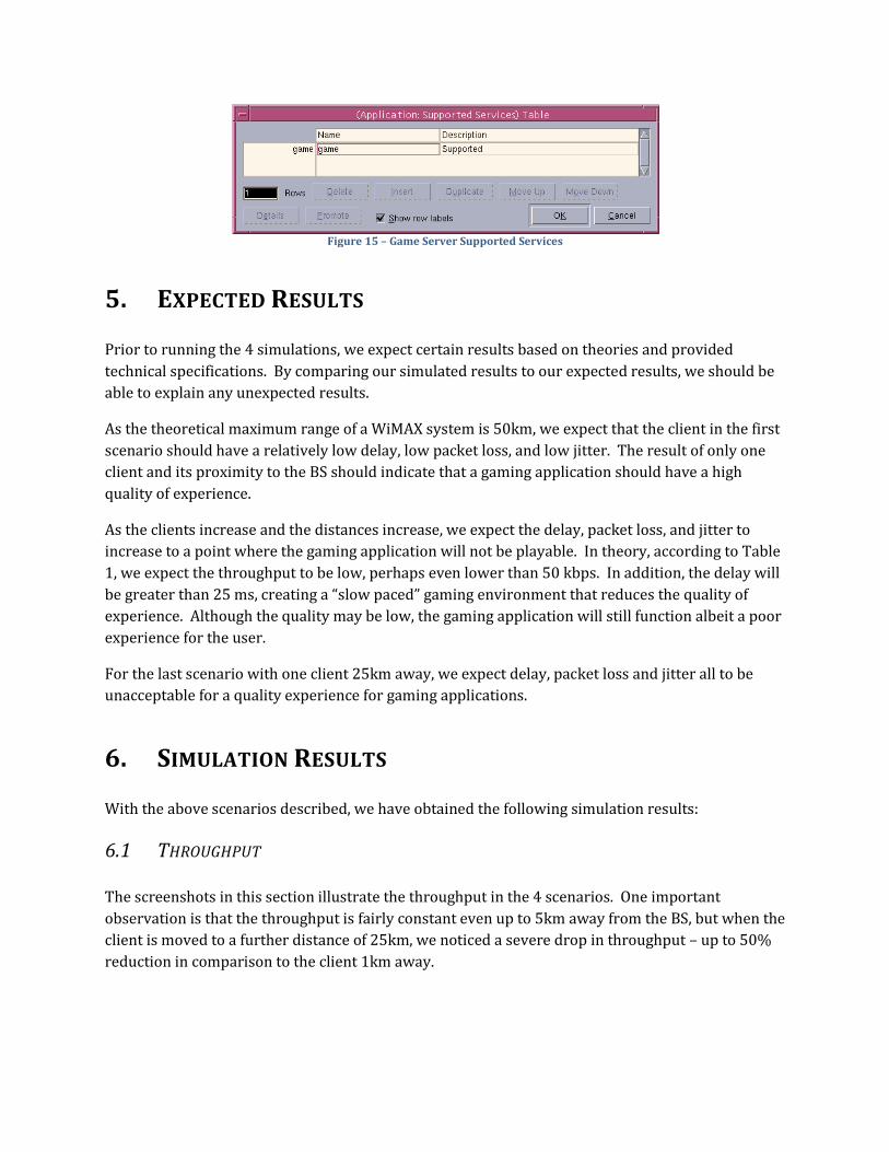
Figure 15 – Game Server Supported Services
5. EXPECTED RESULTS
Prior to running the 4 simulations, we expect certain results based on theories and provided
technical specifications. By comparing our simulated results to our expected results, we should be
able to explain any unexpected results.
As the theoretical maximum range of a WiMAX system is 50km, we expect that the client in the first
scenario should have a relatively low delay, low packet loss, and low jitter. The result of only one
client and its proximity to the BS should indicate that a gaming application should have a high
quality of experience.
As the clients increase and the distances increase, we expect the delay, packet loss, and jitter to
increase to a point where the gaming application will not be playable. In theory, according to Table
1, we expect the throughput to be low, perhaps even lower than 50 kbps. In addition, the delay will
be greater than 25 ms, creating a “slow paced” gaming environment that reduces the quality of
experience. Although the quality may be low, the gaming application will still function albeit a poor
experience for the user.
For the last scenario with one client 25km away, we expect delay, packet loss and jitter all to be
unacceptable for a quality experience for gaming applications.
6. SIMULATION RESULTS
With the above scenarios described, we have obtained the following simulation results:
6.1 THROUGHPUT
The screenshots in this section illustrate the throughput in the 4 scenarios. One important
observation is that the throughput is fairly constant even up to 5km away from the BS, but when the
client is moved to a further distance of 25km, we noticed a severe drop in throughput – up to 50%
reduction in comparison to the client 1km away.
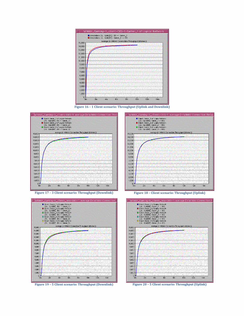
Figure 16 – 1 Client scenario: Throughput (Uplink and Downlink)
Figure 17 – 3 Client scenario: Throughput (Downlink)
Figure 18 – Client scenario: Throughput (Uplink)
Figure 19 – 5 Client scenario: Throughput (Downlink)
Figure 20 – 5 Client scenario: Throughput (Uplink)
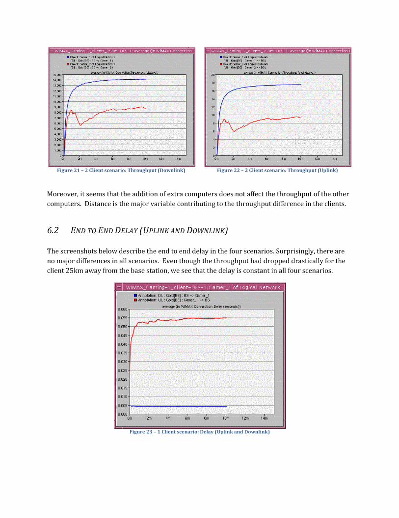
Figure 21 – 2 Client scenario: Throughput (Downlink)
Figure 22 – 2 Client scenario: Throughput (Uplink)
Moreover, it seems that the addition of extra computers does not affect the throughput of the other
computers. Distance is the major variable contributing to the throughput difference in the clients.
6.2 END TO END DELAY (UPLINK AND DOWNLINK)
The screenshots below describe the end to end delay in the four scenarios. Surprisingly, there are
no major differences in all scenarios. Even though the throughput had dropped drastically for the
client 25km away from the base station, we see that the delay is constant in all four scenarios.
Figure 23 – 1 Client scenario: Delay (Uplink and Downlink)
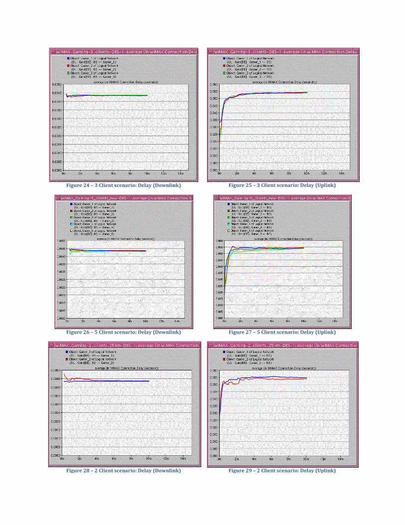
Figure 24 – 3 Client scenario: Delay (Downlink)
Figure 25 – 3 Client scenario: Delay (Uplink)
Figure 26 – 5 Client scenario: Delay (Downlink)
Figure 27 – 5 Client scenario: Delay (Uplink)
Figure 28 – 2 Client scenario: Delay (Downlink)
Figure 29 – 2 Client scenario: Delay (Uplink)
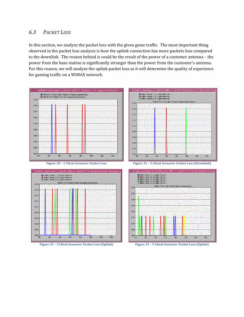
6.3 PACKET LOSS
In this section, we analyze the packet loss with the given game traffic. The most important thing
observed in the packet loss analysis is how the uplink connection has more packets loss compared
to the downlink. The reason behind is could be the result of the power of a customer antenna – the
power from the base station is significantly stronger than the power from the customer’s antenna.
For this reason, we will analyze the uplink packet loss as it will determine the quality of experience
for gaming traffic on a WiMAX network.
Figure 30 – 1 Client Scenario: Packet Loss
Figure 31 – 3 Client Scenario: Packet Loss (Downlink)
Figure 32 – 3 Client Scenario: Packet Loss (Uplink)
Figure 33 – 5 Client Scenario: Packet Loss (Uplink)
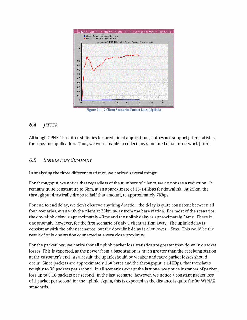
Figure 34 – 2 Client Scenario: Packet Loss (Uplink)
6.4 JITTER
Although OPNET has jitter statistics for predefined applications, it does not support jitter statistics
for a custom application. Thus, we were unable to collect any simulated data for network jitter.
6.5 SIMULATION SUMMARY
In analyzing the three different statistics, we noticed several things:
For throughput, we notice that regardless of the numbers of clients, we do not see a reduction. It
remains quite constant up to 5km, at an approximate of 13-14Kbps for downlink. At 25km, the
throughput drastically drops to half that amount, to approximately 7Kbps.
For end to end delay, we don’t observe anything drastic – the delay is quite consistent between all
four scenarios, even with the client at 25km away from the base station. For most of the scenarios,
the downlink delay is approximately 43ms and the uplink delay is approximately 54ms. There is
one anomaly, however, for the first scenario of only 1 client at 1km away. The uplink delay is
consistent with the other scenarios, but the downlink delay is a lot lower – 5ms. This could be the
result of only one station connected at a very close proximity.
For the packet loss, we notice that all uplink packet loss statistics are greater than downlink packet
losses. This is expected, as the power from a base station is much greater than the receiving station
at the customer’s end. As a result, the uplink should be weaker and more packet losses should
occur. Since packets are approximately 160 bytes and the throughput is 14KBps, that translates
roughly to 90 packets per second. In all scenarios except the last one, we notice instances of packet
loss up to 0.18 packets per second. In the last scenario, however, we notice a constant packet loss
of 1 packet per second for the uplink. Again, this is expected as the distance is quite far for WiMAX
standards.
7. CONCLUSION AND FUTURE WORK 7.1 CONCLUSION
Our project explored the possibility and feasibility of interactive multiplayer game traffic on WiMAX
wireless networks as a solution to traditional landline methods. By using OPNET, we simulated 4
scenarios to test for throughput, delay, jitter, and packet in regards with game traffic. In addition,
we have also gathered WiMAX results to determine the physical capabilities, independent of game
traffic.
By creating custom task, application, and profile definitions we modeled the gaming traffic from
Counter Strike and integrated it with our WiMAX network. The results were achieved all indicated
that WiMAX will be able to support this genre of multiplayer games. Unfortunately, without jitter
results, we cannot reach a conclusive answer that WiMAX will be able to support a high quality of
experience. Jitter results aside, the other results meet the demands for interactive multiplayer
gaming traffic:
The throughput was sufficient at 14Kbps as Counter Strike and similar games have a
low bandwidth requirement. At 25km away, throughput reduced drastically and
may not be able to provide a seamless experience.
The end to end delay was fairly consistent in all scenarios at approximately 43ms
for downlink and 54ms for uplink, even with the client at 25km away.
The uplink packet loss was fairly low – approximately 0.19 packets per second for
the first three scenarios, and 1 packet per second for the last scenario.
With these results, we can conclude that WiMAX will be able to support the genre of interactive
multiplayer FPS games. With jitter information, our results will be more accurate and a
quantitative measure of the quality of experience can be obtained.
7.2 FUTURE WORK
Although our approximated statistics is a good estimate of the gaming traffic, we could increase our
accuracy by incorporating game traffic traces available at Worchester Polytechnic Institute [7].
Unfortunately, the game traces are done in specific configurations and each scenario would requir a
precise layout.
In addition, while Counter Strike is still a popular game, there are newer games that have been
gaining a significant amount of market share. Moreover, Counter Strike only fulfills one type of
genre – there are other genres such as Real Time Strategy and Role Playing Game, both having
different demands in a network. Further research and simulation can confirm WiMAX’s capability
of supporting this class of applications. Lastly, although most users who are using game
applications are fixed, there is the possibility of mobile users. Simulating a mobile client with game
traffic could also determine if WiMAX can provide something unique; the ability for users to be
mobile.
8. REFERENCES
[1] Johannes Farber, Network game traffic modeling, Proceedings of the 1st workshop on Network
and system support for games, p.53-57, Apr 16-17, 2002, Braunschweig, Germany.
[2] “Cisco virtual networking index,” [Online], Available:
http://www.cisco.com/en/US/solutions/collateral/ns341/ns525/ns537/ns705/ns827/white_
paper_c11-481360_ns827_Networking_Solutions_White_Paper.html [Accessed: Mar 23, 2010].
[3] “WiMAX Application Classes,” [Online]. Available:
http://www.wimaxforum.org/technology/downloads/Mobile_WiMAX_Part1_Overview_and_Pe
rformance.pdf p. 48 [Accessed: Mar 23, 2010].
[4] “Quality of Experience Requirements,” [Online]. Available: http://www.broadband-
forum.org/technical/download/TR-126.pdf p.79 [Accessed: Mar 24, 2010].
[5] “Starcraft and Counterstrike game traces,” [Online]. Available:
http://perform.wpi.edu/downloads/#net-game
[6] S. Chiu, “Online Interactive Game Traffic,” [Online]. Available:
http://www.ensc.sfu.ca/~ljilja/ENSC835/Spring06/Projects/chiu/Report.pdf
[7] W. Hrudey, “Streaming Video Content over IEEE 802.16/WiMAX,” [Online]. Available:
http://www.ensc.sfu.ca/~ljilja/ENSC835/Spring08/Projects/hrudey/whrudey_WiMAX.pdf
[8] J. Yoo, “Performance Evaluation of Voice Over IP on WiMAX and Wi-Fi based Networks,”
[Online]. Available:
http://www.ensc.sfu.ca/~ljilja/ENSC427/Spring09/Projects/team1/ensc427-finalreport.pdf
[9] Z. Yang, et al., "Downlink Performance of WiMAX Broadband from High Altitude Platform and
Terrestrial Deployments sharing a common 3.5GHz band," presented at 2005 IST Mobile and
Wireless Communications Summit, Dresden, Germany, 2005.
[10] S. Lloyd, “Challenges of Mobile WiMAX RF Transceivers,” Solid-State and Integrated Circuit
Technology, 2006. ICSICT '06. 8th International Conference on, Oct. 2006, pp. 1821-1824.
[11] “WiMAX Transmission Power,” [Online]. Available:
http://www.wimaxcom.net/2008/11/wimax-transmit-power.html
[12] OPNET, “Introduction to WiMAX Modeling for Network R&D and Planning,” OPNET
Modeller, lab1571. [Online].
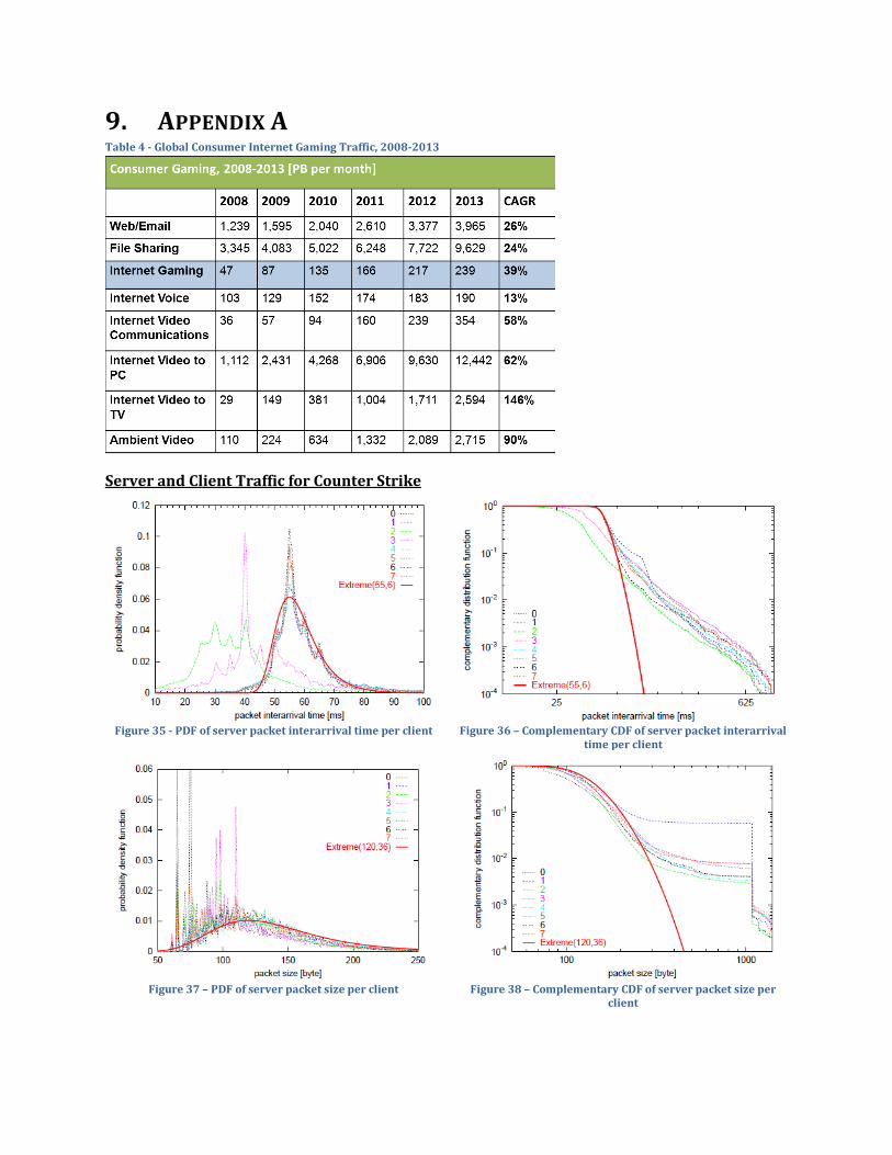
9. APPENDIX A Table 4 - Global Consumer Internet Gaming Traffic, 2008-2013
Server and Client Traffic for Counter Strike
Figure 35 - PDF of server packet interarrival time per client
Figure 36 – Complementary CDF of server packet interarrival time per client
Figure 37 – PDF of server packet size per client
Figure 38 – Complementary CDF of server packet size per
client
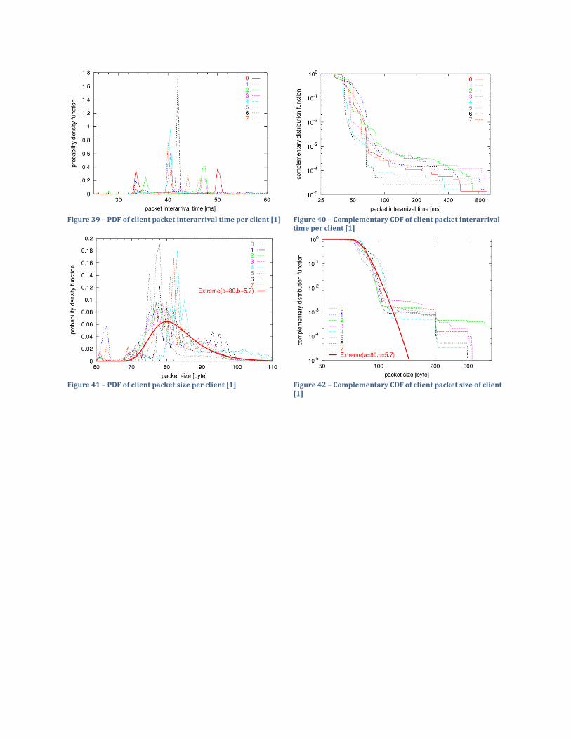
Figure 39 – PDF of client packet interarrival time per client [1]
Figure 40 – Complementary CDF of client packet interarrival time per client [1]
Figure 41 – PDF of client packet size per client [1]
Figure 42 – Complementary CDF of client packet size of client [1]
Recommended


![ENSC427:CommunicationNetworks,Spring2012 ... › ~ljilja › ENSC427 › Spring12 › Projects › team12 › ENSC...References’! [1]A.Zaballos,G.Corral,I.Serra,J.Abella,"TestingNetworkSecurity%](https://img.pdfslide.net/doc/110x75/5f0ec6637e708231d440e03f/ensc427communicationnetworksspring2012-a-ljilja-a-ensc427-a-spring12.jpg)

![Introduction/Motivation - Simon Fraser Universityljilja/ENSC427/Spring15/Projects/team3/ENSC...[8] S. Grafling, P. Mahonen and J. Riihijarvi, "Performance evaluation of IEEE 1609 WAVE](https://img.pdfslide.net/doc/110x75/5f700439eee606489707ae55/introductionmotivation-simon-fraser-ljiljaensc427spring15projectsteam3ensc.jpg)