8/8/2019 Estro Burner Control
http://slidepdf.com/reader/full/estro-burner-control 1/18
CAUTION: Operation of combustion equip-ment can be hazardous resulting in bodily in-jury or equipment damage. Each burner shouldbe supervised by a combustion safeguard and
only qualified personnel should install, makesystem adjustments and perform any requiredservice.
NOTICE: PYRONICS practices apolicy of continuous improvement inthe design of its products. It reservesthe right to change the specifcations
at any time without prior notice.
MICROPROCESSORBURNER CONTROL
ESTRO SERIES
MODEL: 7500
Revision: 2 B U L L E T I N
7 5 0 0
FEATURES
The ESTRO is a microprocessor-operated flame controlling device equipped with
inputs and outputs for the ignition and control of commercial and industrial
burners. There are three different versions of the ESTRO:
ESTRO B: Designed for two-stage or pilot ignited burners (pilot and main gas
valves). May be remote controlled via electrical and serial signals with powered
output when the burner is operating.
ESTRO C: Designed for single-stage or direct spark ignited burners (only one
gas valve). May be remote controlled via electrical and serial signals with
normally open output when the burner is operating.
ESTRO Q: Designed for single-stage or direct spark ignited burners (only one
gas valve). May be remote controlled via serial signals.
An EXP-1 expansion card may be added to any of the three ESTRO versions to
control a burner equipped with air damper, blower, and pressure switch (packaged
burner).
On the front panel there is a lock/reset button, a cycle display, and flame signal
indicator. The ESTRO is supplied in a strong thermosetting casing equipped with
holes for the cable outputs which may be cabled in advance if required.
DESCRIPTION
Supply voltage .................................................................................. 115/230 V
Frequency ............................................................................................. 50/60 Hz
Power consumption (without outputs) ..............................................4 VA max.
Operating temperature ..................................................................... 30 - 140 oF.
Storage temperature ............................................................................ 5 - 175 oF.
Protection class (when wiring, use adequate connectors) ........NEMA 3, 3S, 13 Mounting position .......................................................................................Any
Load protection fuse ................................................................................ 3.15 A
Device protection fuse .................................................................................. 1 A
Detector voltage ................................................................................... 300 VAC
Minimum ionization current ...................................................................... 3 µA
Flame current limitation .......................................................................... 3.2 mA
Flame signal display ..............................................................................0-90 µA
Prepurge time (see Note 1 below) .......................................................0-255 sec.
First safety time ....................................................................................1-25 sec.
Main burner stabilization time ..............................................................1-25 sec.
Reaction time .........................................................................................1-20 sec.
Post-purge time (see Note 1 below) ....................................................0-255 sec.
Auto shutoff (optional) ..............................................................within 24 hours
Optional input voltages ............................................ 24, 48, 115, 230 V AC/DC Dimensions ...................................................................... 7-7/8” x 4-3/4” x 3-5/8”
Weight ..................................................................................................... 2.6 Lbs.
Flame detecting device .............................................................Flame Rod or UV
Rod or UV detector lead length ............................................................. < 100 ft.
NOTE 1: WHEN THE EXP-1 EXPANSION CARD IS NOT PROVIDED,
THESE VALUES MUST BE CONSIDERED AS IDLE TIMES.
Flame control for single or two-stage piloted
or direct spark ignited, continuous or discon-
tinuous gas or oil burners
Flame control for packaged burners managing
the complete ignition cycle (blower, air
damper, air pressure switch)
Flame control suitable for flame detection by
means of flame rod, unirod or UV tube
(also in combination with each other)
Flame control with serial interface for remote
control in multi-burner systems
APPLICATIONS
APPROVALS
Evaluated to the applicable CSA and
ANSI/UL standards
ORDAN THERMAL PRODUCTS LTDCombustion Equipment & Controls for Industry
21 Amber St # 9, Markham Ontario Canada L3R 4Z3Tel: (905) 475-9292 Fax: (905) 475-3286
www.ordanthermal.com
8/8/2019 Estro Burner Control
http://slidepdf.com/reader/full/estro-burner-control 2/18
MICROPROCESSORBURNER CONTROL
ESTRO SERIES
BULLETIN 7500
PAGE NO. 2
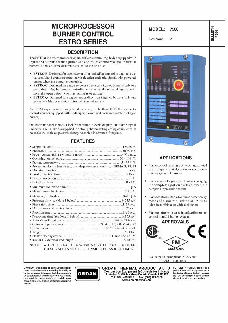
REAR PANEL
Item Description
1 Main terminal block for connections2 Load protection fuse
3 Terminal block for serial communication
4 Expansion board EXP-1 inlet
5 Terminal block for EXP-1 expansion card
8/8/2019 Estro Burner Control
http://slidepdf.com/reader/full/estro-burner-control 3/18
CAUTION: Operation of combustion equip-ment can be hazardous resulting in bodily in-jury or equipment damage. Each burner shouldbe supervised by a combustion safeguard and
only qualified personnel should install, makesystem adjustments and perform any requiredservice.
NOTICE: PYRONICS practices apolicy of continuous improvement inthe design of its products. It reservesthe right to change the specifcations
at any time without prior notice.
BULLETIN 7500
PAGE NO. 3
MICROPROCESSORBURNER CONTROL
ESTRO SERIES
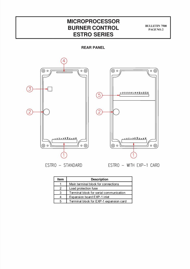
ESTRO-B CONNECTIONS
Terminal Description Terminal Description
A Lockout signal output 6 Main gas valve neutral
B Remote reset / lockout input 7 Ignition transformer line
1 Power supply line 8 Ignition transformer neutral
2 Power supply neutral 9 Rod or phototube negative end
3 Pilot gas valve line 10 Ground, UV phototube positive end or burner frame
4 Pilot gas valve neutral + Communication input positive end
5 Main gas valve line - Communication input negative end
ORDAN THERMAL PRODUCTS LTDCombustion Equipment & Controls for Industry
21 Amber St # 9, Markham Ontario Canada L3R 4Z3Tel: (905) 475-9292 Fax: (905) 475-3286
www.ordanthermal.com
8/8/2019 Estro Burner Control
http://slidepdf.com/reader/full/estro-burner-control 4/18
MICROPROCESSORBURNER CONTROL
ESTRO SERIES
BULLETIN 7500
PAGE NO. 4
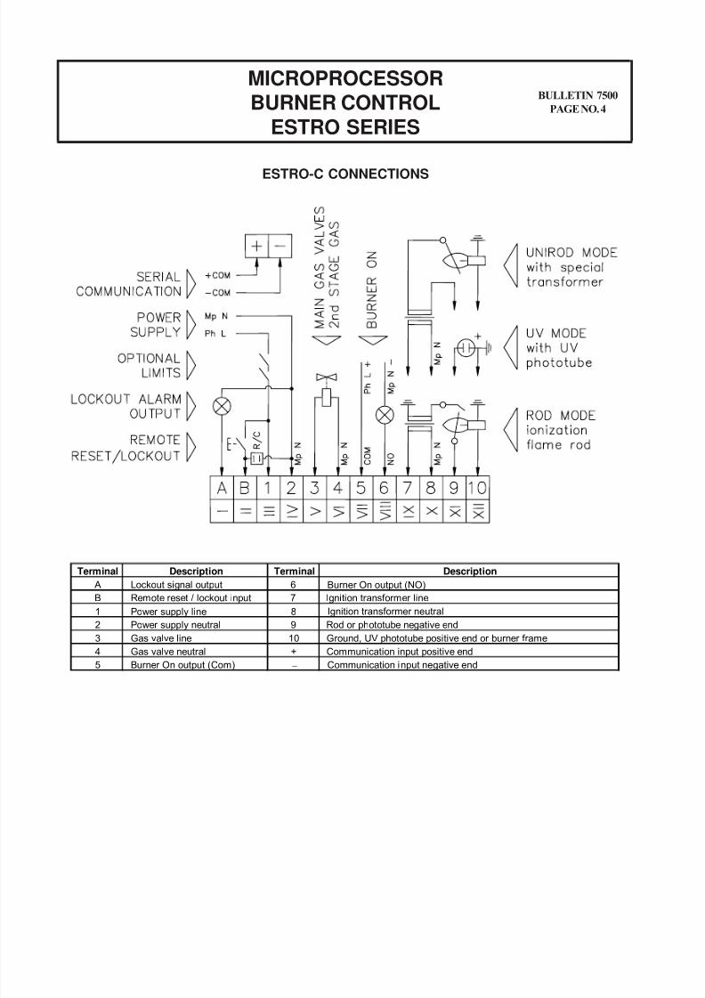
ESTRO-C CONNECTIONS
Terminal Description Terminal Description
A Lockout signal output 6 Burner On output (NO)
B Remote reset / lockout input 7 Ignition transformer line
1 Power supply line 8 Ignition transformer neutral
2 Power supply neutral 9 Rod or phototube negative end
3 Gas valve line 10 Ground, UV phototube positive end or burner frame
4 Gas valve neutral + Communication input positive end
5 Burner On output (Com) - Communication input negative end
8/8/2019 Estro Burner Control
http://slidepdf.com/reader/full/estro-burner-control 5/18
CAUTION: Operation of combustion equip-ment can be hazardous resulting in bodily in-jury or equipment damage. Each burner shouldbe supervised by a combustion safeguard and
only qualified personnel should install, makesystem adjustments and perform any requiredservice.
NOTICE: PYRONICS practices apolicy of continuous improvement inthe design of its products. It reservesthe right to change the specifcations
at any time without prior notice.
BULLETIN 7500
PAGE NO. 5
MICROPROCESSORBURNER CONTROL
ESTRO SERIES
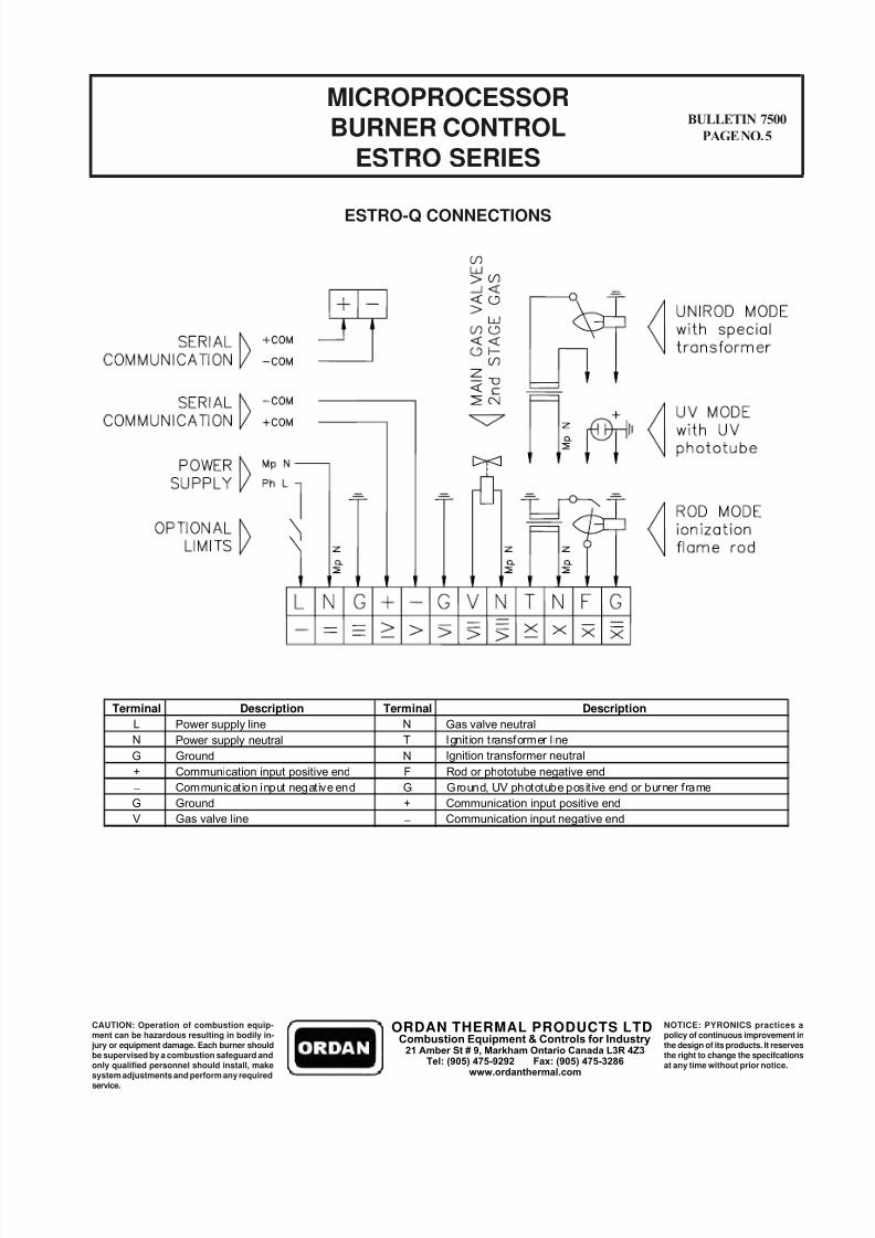
ESTRO-Q CONNECTIONS
Terminal Description Terminal Description
L Power supply line N Gas valve neutral
N Power supply neutral T Ignit ion transformer l ine
G Ground N Ignition transformer neutral
+ Communication input positive end F Rod or phototube negative end
- Communication input negative end G Ground, UV phototube positive end or burner frame
G Ground + Communication input positive end
V Gas valve line - Communication input negative end
ORDAN THERMAL PRODUCTS LTDCombustion Equipment & Controls for Industry
21 Amber St # 9, Markham Ontario Canada L3R 4Z3Tel: (905) 475-9292 Fax: (905) 475-3286
www.ordanthermal.com
8/8/2019 Estro Burner Control
http://slidepdf.com/reader/full/estro-burner-control 6/18
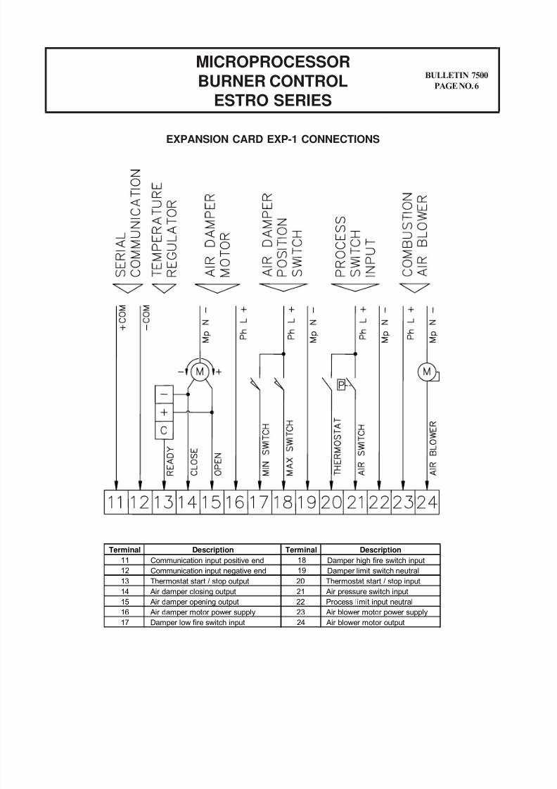
EXPANSION CARD EXP-1 CONNECTIONS
MICROPROCESSOR
BURNER CONTROLESTRO SERIES
BULLETIN 7500
PAGE NO. 6
Terminal Description Terminal Description
11 Communication input positive end 18 Damper high fire switch input
12 Communication input negative end 19 Damper limit switch neutral
13 Thermostat start / stop output 20 Thermostat start / stop input
14 Air damper closing output 21 Air pressure switch input
15 Air damper opening output 22 Process limit input neutral
16 Air damper motor power supply 23 Air blower motor power supply
17 Damper low fire switch input 24 Air blower motor output
8/8/2019 Estro Burner Control
http://slidepdf.com/reader/full/estro-burner-control 7/18
CAUTION: Operation of combustion equip-ment can be hazardous resulting in bodily in-jury or equipment damage. Each burner shouldbe supervised by a combustion safeguard and
only qualified personnel should install, makesystem adjustments and perform any requiredservice.
NOTICE: PYRONICS practices apolicy of continuous improvement inthe design of its products. It reservesthe right to change the specifcations
at any time without prior notice.
BULLETIN 7500
PAGE NO. 7
MICROPROCESSORBURNER CONTROL
ESTRO SERIES
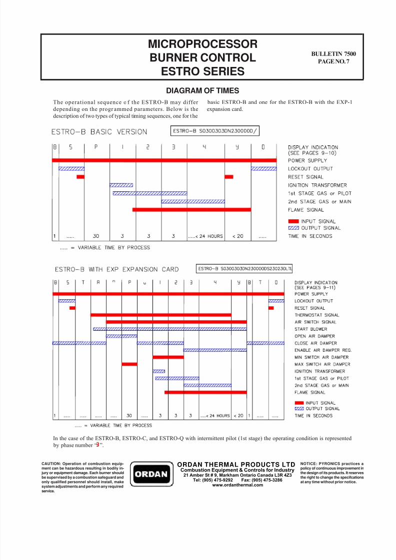
DIAGRAM OF TIMES
The operational sequence o f the ESTRO-B may differ
depending on the progr ammed parameters. Below is the
description of two types of typical timing sequences, one for the
basic ESTRO-B and one for the ESTRO-B with the EXP-1
expansion card.
In the case of the ESTRO-B, ESTRO-C, and ESTRO-Q with intermittent pilot (1st stage) the operating condition is represented
by phase number “ ”.
ORDAN THERMAL PRODUCTS LTDCombustion Equipment & Controls for Industry
21 Amber St # 9, Markham Ontario Canada L3R 4Z3Tel: (905) 475-9292 Fax: (905) 475-3286
www.ordanthermal.com
8/8/2019 Estro Burner Control
http://slidepdf.com/reader/full/estro-burner-control 8/18
INSTALLATION
MICROPROCESSOR
BURNER CONTROLESTRO SERIES
BULLETIN 7500
PAGE NO. 8
Avoid placing the ESTRO near intense magnetic or electric fieldsor other locations that would expose the unit to direct heat or
products of combustion.
The ESTRO must be installed in compliance with the applicable
codes and regulations.
A minimum electrical classification of NEMA 12 is required when
installing the ESTRO on or near a furnace casing, etc..
The ESTRO is intended for permanent connection to the electrical
power supply and should never be fitted with a reversible main
power plug. After installation, check that the connections are
correct prior to delivering power to unit. Reversal of the live/
neutral connections may result in damage to the unit.
Check that the supply voltage and frequency are correct.
Verify that the connected outputs do not exceed the maximum
contacts capacity. Review all technical information, in particular the phase-neutral
polarity when making electrical connections. The type of
conductors and their locations must be suitable for the
application(s).
The flame signal cables must by isolated from the oth er
conductors. Multi-conductor cables may not be used. In addition,
no shielded cables are allowed.
Detection probes and connectors (if any) must be isolated.
Always connect the grounding wire(s).
When using the remote reset connect the RC filter.
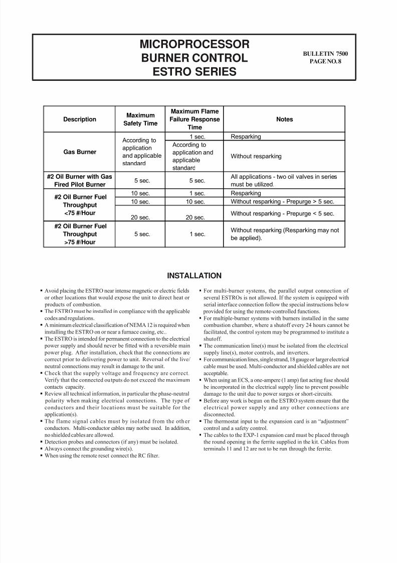
DescriptionMaximum
Safety Time
Maximum Flame
Failure Response
Time
Notes
1 sec. Resparking
According to
application and
applicable
standard
Without resparking
#2 Oil Burner with Gas
Fired Pilot Burner5 sec. 5 sec.
All applications - two oil valves in series
must be utilized.
10 sec. 1 sec. Resparking10 sec. 10 sec. Without resparking - Prepurge > 5 sec.
20 sec. 20 sec.Without resparking - Prepurge < 5 sec.
1 sec.Without resparking (Resparking may not
be applied).
Gas Burner
According to
application
and applicable
standard
#2 Oil Burner Fuel
Throughput
<75 #/Hour
#2 Oil Burner Fuel
Throughput
>75 #/Hour
5 sec.
For multi-burner systems, the parallel output connection of several ESTROs is not allowed. If the system is equipped with
serial interface connection follow the special instructions below
provided for using the remote-controlled functions.
For multiple-burner systems with burners installed in the same
combustion chamber, where a shutoff every 24 hours cannot be
facilitated, the control system may be programmed to institute a
shutoff.
The communication line(s) must be isolated from the electrical
supply line(s), motor controls, and inverters.
For communication lines, single strand, 18 gauge or larger electrical
cable must be used. Multi-conductor and shielded cables are not
acceptable.
When using an ECS, a one-ampere (1 amp) fast acting fuse should
be incorporated in the electrical supply line to prevent possibledamage to the unit due to power surges or short-circuits.
Before any work is begun on the ESTRO system ensure that the
electrical power supply and any other connections are
disconnected.
The thermostat input to the expansion card is an “adjustment”
control and a safety control.
The cables to the EXP-1 expansion card must be placed through
the round opening in the ferrite supplied in the kit. Cables from
terminals 11 and 12 are not to be run through the ferrite.
8/8/2019 Estro Burner Control
http://slidepdf.com/reader/full/estro-burner-control 9/18
CAUTION: Operation of combustion equip-ment can be hazardous resulting in bodily in-jury or equipment damage. Each burner shouldbe supervised by a combustion safeguard and
only qualified personnel should install, makesystem adjustments and perform any requiredservice.
NOTICE: PYRONICS practices apolicy of continuous improvement inthe design of its products. It reservesthe right to change the specifcations
at any time without prior notice.
STATUS DISPLAY
BULLETIN 7500
PAGE NO. 9
MICROPROCESSORBURNER CONTROL
ESTRO SERIES
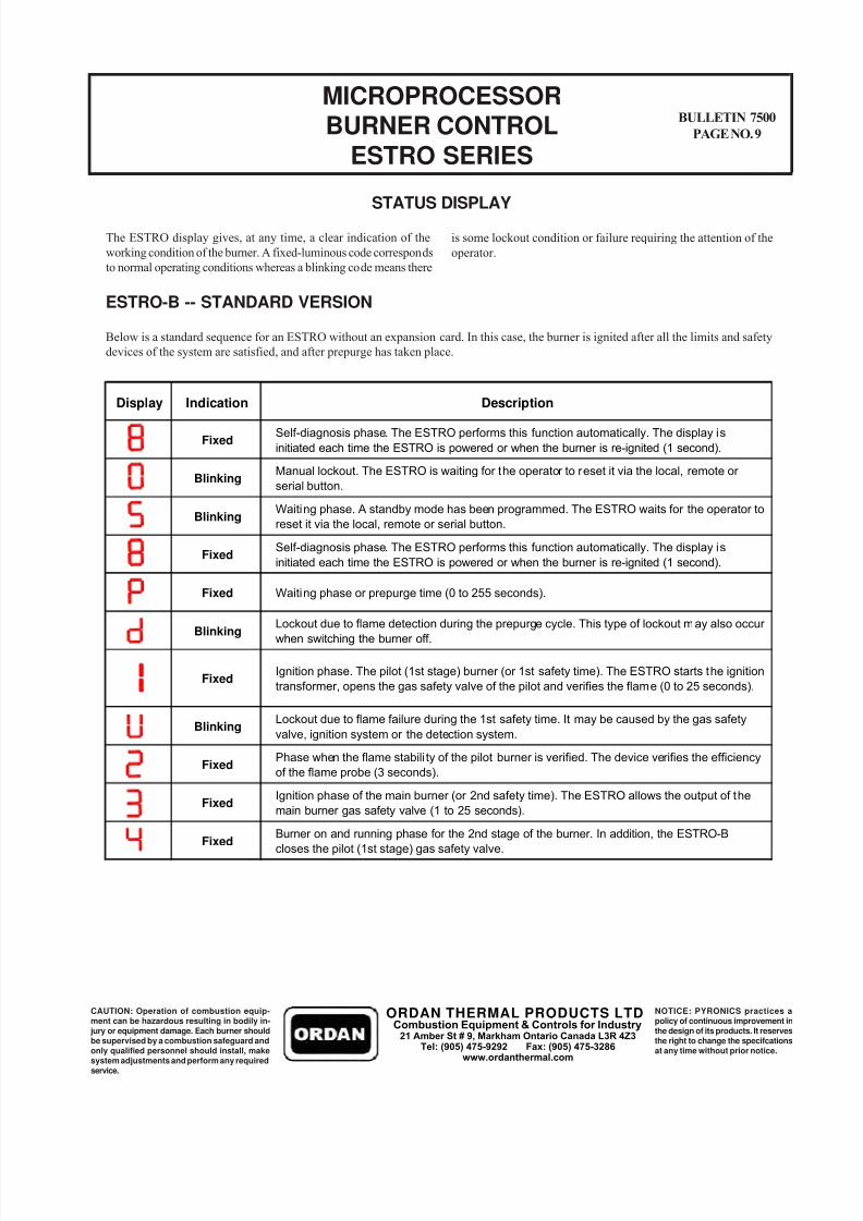
The ESTRO display gives, at any time, a clear indication of the
working condition of the burner. A fixed-luminous code corresponds
to normal operating conditions whereas a blinking code means there
is some lockout condition or failure requiring the attention of the
operator.
ESTRO-B -- STANDARD VERSION
Below is a standard sequence for an ESTRO without an expansion card. In this case, the burner is ignited after all the limits and safety
devices of the system are satisfied, and after prepurge has taken place.
Display Indication Description
Fixed
Blinking
Blinking
Self-diagnosis phase. The ESTRO performs this function automatically. The display is
initiated each time the ESTRO is powered or when the burner is re-ignited (1 second).
Manual lockout. The ESTRO is waiting for the operator to reset it via the local, remote or
serial button.
Waiting phase. A standby mode has been programmed. The ESTRO waits for the operator to
reset it via the local, remote or serial button.
Fixed
Fixed
Fixed
Blinking
Fixed
Blinking
Fixed
Fixed
Self-diagnosis phase. The ESTRO performs this function automatically. The display is
initiated each time the ESTRO is powered or when the burner is re-ignited (1 second).
Waiting phase or prepurge time (0 to 255 seconds).
Lockout due to flame detection during the prepurge cycle. This type of lockout may also occur
when switching the burner off.
Burner on and running phase for the 2nd stage of the burner. In addition, the ESTRO-B
closes the pilot (1st stage) gas safety valve.
Ignition phase. The pilot (1st stage) burner (or 1st safety time). The ESTRO starts the ignition
transformer, opens the gas safety valve of the pilot and verifies the flame (0 to 25 seconds).
Lockout due to flame failure during the 1st safety time. It may be caused by the gas safety
valve, ignition system or the detection system.
Phase when the flame stabili ty of the pilot burner is verified. The device verifies the efficiency
of the flame probe (3 seconds).
Ignition phase of the main burner (or 2nd safety time). The ESTRO allows the output of the
main burner gas safety valve (1 to 25 seconds).
ORDAN THERMAL PRODUCTS LTDCombustion Equipment & Controls for Industry
21 Amber St # 9, Markham Ontario Canada L3R 4Z3Tel: (905) 475-9292 Fax: (905) 475-3286
www.ordanthermal.com
8/8/2019 Estro Burner Control
http://slidepdf.com/reader/full/estro-burner-control 10/18
MICROPROCESSOR
BURNER CONTROLESTRO SERIES
BULLETIN 7500
PAGE NO. 10
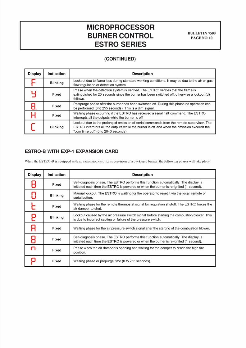
ESTRO-B WITH EXP-1 EXPANSION CARD
When the ESTRO-B is equipped with an expansion card for supervision of a packaged burner, the following phases will take place:
(CONTINUED)
Display Indication Description
FixedWaiting phase for the remote thermostat signal for regulation shutoff. The ESTRO forces the
air damper to shut.
Self-diagnosis phase. The ESTRO performs this function automatically. The display is
initiated each time the ESTRO is powered or when the burner is re-ignited (1 second).
Manual lockout. The ESTRO is waiting for the operator to reset it via the local, remote or
serial button.Blinking
Fixed
BlinkingLockout caused by the air pressure switch signal before starting the combustion blower. This
is due to incorrect cabling or failure of the pressure switch.
Fixed
Fixed
Self-diagnosis phase. The ESTRO performs this function automatically. The display is
initiated each time the ESTRO is powered or when the burner is re-ignited (1 second).
Waiting phase for the air pressure switch signal after the starting of the combustion blower.
Phase when the air damper is opening and waiting for the damper to reach the high fire
position.
Waiting phase or prepurge time (0 to 255 seconds).
Fixed
Fixed
Display Indication Description
Fixed
BlinkingLockout due to flame loss during standard working conditions. I t may be due to the air or gas
flow regulation or detection system.
Phase when the detection system is verified. The ESTRO verifies that the flame is
extinguished for 20 seconds since the burner has been switched off, otherwise a lockout (d)
follows.
Postpurge phase after the burner has been switched off. During this phase no operation can
be performed (0 to 255 seconds). This is a dim signal.
Waiting phase occurring if the ESTRO has received a serial halt command. The ESTRO
interrupts all the outputs while the burner is off.
Lockout due to the prolonged omission of serial commands from the remote supervisor. The
ESTRO interrupts all the outputs while the burner is off and when the omission exceeds the
"com time out" (0 to 2040 seconds).
Fixed
Blinking
Fixed
8/8/2019 Estro Burner Control
http://slidepdf.com/reader/full/estro-burner-control 11/18
CAUTION: Operation of combustion equip-ment can be hazardous resulting in bodily in-jury or equipment damage. Each burner shouldbe supervised by a combustion safeguard and
only qualified personnel should install, makesystem adjustments and perform any requiredservice.
NOTICE: PYRONICS practices apolicy of continuous improvement inthe design of its products. It reservesthe right to change the specifcations
at any time without prior notice.
BULLETIN 7500
PAGE NO. 11
MICROPROCESSORBURNER CONTROL
ESTRO SERIES
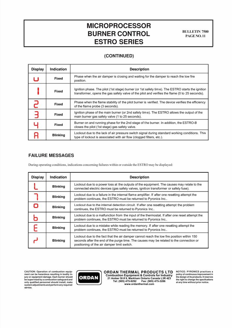
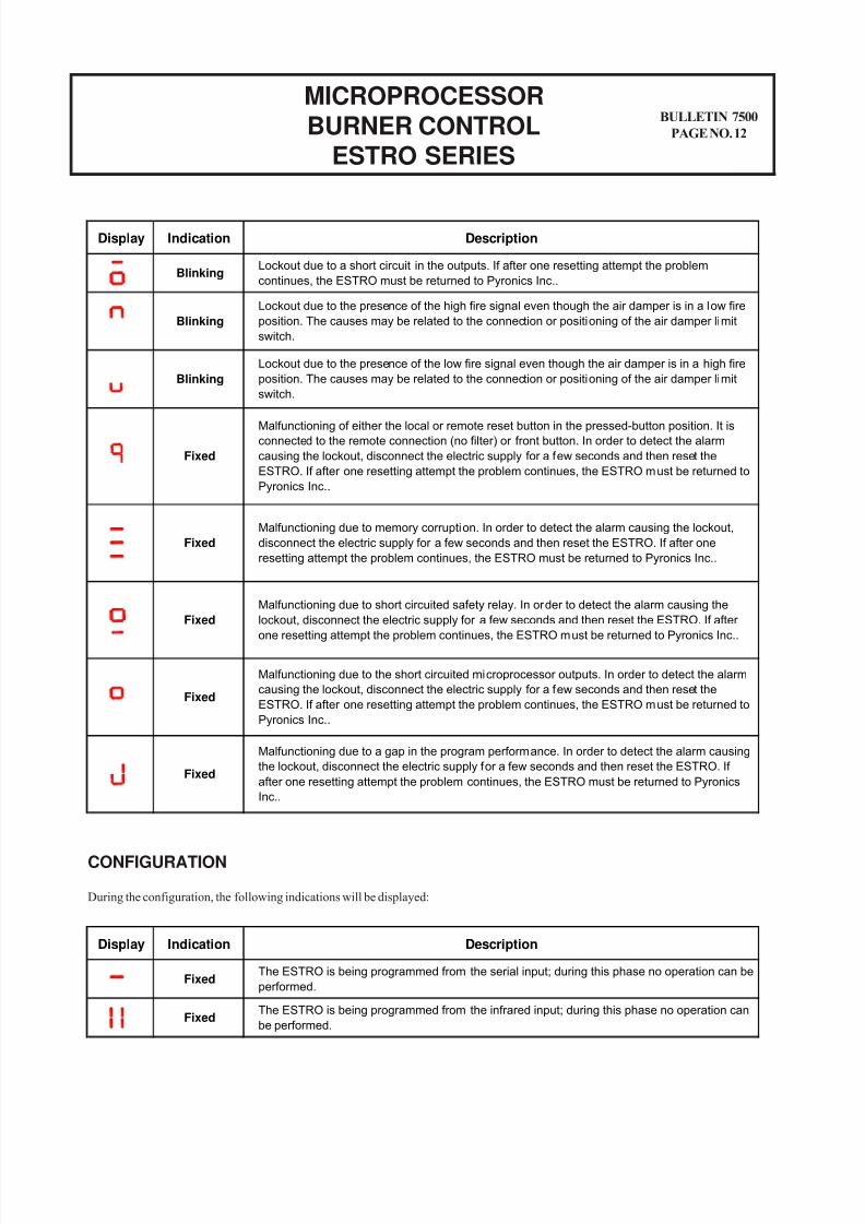
FAILURE MESSAGES
During operating conditions, indications concerning failures within or outside the ESTRO may be displayed:
(CONTINUED)
Display Indication Description
Phase when the air damper is closing and waiting for the damper to reach the low fire
position.Fixed
Blinking
Fixed
Ignition phase of the main burner (or 2nd safety time). The ESTRO allows the output of themain burner gas safety valve (1 to 25 seconds).
FixedBurner on and running phase for the 2nd stage of the burner. In addition, the ESTRO-B
closes the pilot (1st stage) gas safety valve.
Fixed
Lockout due to the lack of air pressure switch signal during standard working conditions. This
type of lockout is associated with air flow (clogged filters, etc.).
Ignition phase. The pilot (1st stage) burner (or 1st safety time). The ESTRO starts the ignition
transformer, opens the gas safety valve of the pilot and verifies the flame (0 to 25 seconds).
FixedPhase when the flame stability of the pilot burner is verified. The device verifies the efficiency
of the flame probe (3 seconds).
Display Indication Description
Blinking
Blinking
Blinking
Blinking
Blinking
Blinking
Lockout due to a power loss at the outputs of the equipment. The causes may relate to the
connected electric devices (gas safety valves, ignition transformer or safety fuse).
Lockout due to a failure in the internal flame amplifier. If after one resetting attempt the
problem continues, the ESTRO must be returned to Pyronics Inc..
Lockout due to the internal detection circuit. If after one resetting attempt the problem
continues, the ESTRO must be returned to Pyronics Inc..
Lockout due to a malfunction from the input of the thermostat. If after one reset attempt the
problem continues, the ESTRO must be returned to Pyronics Inc..
Lockout due to a mistake while reading the memory. If after one resetting attempt theproblem continues, the ESTRO must be returned to Pyronics Inc..
Lockout due to the fact that the air damper cannot reach the low fire position within 150
seconds after the end of the purge time. The causes may be related to the connection or
positioning of the air damper limit switch.
ORDAN THERMAL PRODUCTS LTDCombustion Equipment & Controls for Industry
21 Amber St # 9, Markham Ontario Canada L3R 4Z3Tel: (905) 475-9292 Fax: (905) 475-3286
www.ordanthermal.com
8/8/2019 Estro Burner Control
http://slidepdf.com/reader/full/estro-burner-control 12/18
MICROPROCESSOR
BURNER CONTROLESTRO SERIES
BULLETIN 7500
PAGE NO. 12
CONFIGURATION
During the configuration, the following indications will be displayed:
Display Indication Description
Blinking
Blinking
Blinking
Fixed
Fixed
Fixed
Fixed
Fixed
Lockout due to a short circuit in the outputs. If after one resetting attempt the problem
continues, the ESTRO must be returned to Pyronics Inc..
Lockout due to the presence of the high fire signal even though the air damper is in a low fire
position. The causes may be related to the connection or positioning of the air damper limit
switch.
Lockout due to the presence of the low fire signal even though the air damper is in a high fire
position. The causes may be related to the connection or positioning of the air damper limit
switch.
Malfunctioning of either the local or remote reset button in the pressed-button position. It isconnected to the remote connection (no filter) or front button. In order to detect the alarm
causing the lockout, disconnect the electric supply for a few seconds and then reset the
ESTRO. If after one resetting attempt the problem continues, the ESTRO must be returned to
Pyronics Inc..
Malfunctioning due to memory corruption. In order to detect the alarm causing the lockout,
disconnect the electric supply for a few seconds and then reset the ESTRO. If after one
resetting attempt the problem continues, the ESTRO must be returned to Pyronics Inc..
Malfunctioning due to short circuited safety relay. In order to detect the alarm causing the
lockout, disconnect the electric supply for a few seconds and then reset the ESTRO. If after
one resetting attempt the problem continues, the ESTRO must be returned to Pyronics Inc..
Malfunctioning due to the short circuited microprocessor outputs. In order to detect the alarm
causing the lockout, disconnect the electric supply for a few seconds and then reset the
ESTRO. If after one resetting attempt the problem continues, the ESTRO must be returned to
Pyronics Inc..
Malfunctioning due to a gap in the program performance. In order to detect the alarm causing
the lockout, disconnect the electric supply for a few seconds and then reset the ESTRO. If
after one resetting attempt the problem continues, the ESTRO must be returned to Pyronics
Inc..
Display Indication Description
Fixed
Fixed
The ESTRO is being programmed from the serial input; during this phase no operation can be
performed.
The ESTRO is being programmed from the infrared input; during this phase no operation can
be performed.
8/8/2019 Estro Burner Control
http://slidepdf.com/reader/full/estro-burner-control 13/18
CAUTION: Operation of combustion equip-ment can be hazardous resulting in bodily in-jury or equipment damage. Each burner shouldbe supervised by a combustion safeguard and
only qualified personnel should install, makesystem adjustments and perform any requiredservice.
NOTICE: PYRONICS practices apolicy of continuous improvement inthe design of its products. It reservesthe right to change the specifcations
at any time without prior notice.
BULLETIN 7500
PAGE NO. 13
MICROPROCESSORBURNER CONTROL
ESTRO SERIES
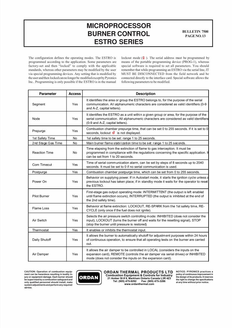
The configuration defines the operating modes. The ESTRO is
programmed according to the application. Some parameters are
factory-set and then “locked” to comply with the applicable
standards, whereas other parameters may be modified by the user
via special programming devices. Any setting that is modified by
the user and then locked can no longer be modified except by Pyronics
Inc.. Programming is only possible if the ESTRO is in the manual
lockout mode ( ). The serial address must be programmed by
means of the portable programming device (PROG-1), whereas
special software is required to set all parameters. You should
remember that while programming an ESTRO via the serial line, IT
MUST BE DISCONNECTED from the field network and be
connected directly to the interface card. Special software allows the
following parameters to be modified.
Parameter Access Description
1st Safety Time No 1st safety time to be set: range 1 to 25 seconds.
2nd Stage Gas Time No Main burner flame stabilization time to be set: range 1 to 25 seconds.
Postpurge Yes Combustion chamber postpurge time, which can be set from 0 to 255 seconds.
Thermostat Yes It enables or inhibits the thermostat input.
It identifies the area or group the ESTRO belongs to, for the purpose of the serial
communication. All alphanumeric characters are considered as valid identifiers (0-9
and A-Z, capital letters).
YesSegment
Yes
It identifies the ESTRO as a unit within a given group or area, for the purpose of the
serial communication. All alphanumeric characters are considered as valid identifiers
(0-9 and A-Z, capital letters).
Node
Time elapsing from the extinction of flame to gas interception. It must be
programmed in compliance with the regulations concerning the specific application. It
can be set from 1 to 20 seconds.
NoReaction Time
Combustion chamber prepurge time, that can be set 0 to 255 seconds. If it is set to 0
seconds, lockout is not displayed.
Time of serial communication alarm, can be set by steps of 8 seconds up to 2040
seconds. It must be set to 0 if no serial communication is used.
Behavior on supplying power. If in Autostart mode, it starts the ignition cycle unless a
previous lockout has taken place; if in standby mode it waits for the operator to reset
the ESTRO.
YesPower On
First-stage gas output operating mode: INTERMITTENT (the output is left enabled
until flame extinction occurs), INTERRUPTED (the output is inhibited at the end of
the 2nd safety time).
YesPilot Burner
Behavior at flame extinction: LOCKOUT, RE-SPARK from the 1st safety time, RE-
CYCLE (only once if the fuel does not ignite).Flame Loss
Selects the air pressure switch controlling mode: INHIBITED (does not consider the
input), LOCKOUT (turns the burner off and waits for the resetting signal), STOP
(stop the burner until pressure is restored).
It allows the burner to automatically shutoff for adjustment purposes within 24 hours
of continuous operation, to ensure that all operating tests on the burner are carried
out.
It allows the air damper to be controlled in LOCAL (considers the inputs on the
expansion card), REMOTE (controls the air damper via serial drives) or INHIBITED
mode (does not consider the inputs on the expansion card).
Yes
Yes
Yes
Yes
Air Switch
Daily Shutoff
Air Damper
YesPrepurge
Com Timeout Yes
ORDAN THERMAL PRODUCTS LTDCombustion Equipment & Controls for Industry
21 Amber St # 9, Markham Ontario Canada L3R 4Z3Tel: (905) 475-9292 Fax: (905) 475-3286
www.ordanthermal.com
8/8/2019 Estro Burner Control
http://slidepdf.com/reader/full/estro-burner-control 14/18
MICROPROCESSOR
BURNER CONTROLESTRO SERIES
BULLETIN 7500
PAGE NO. 14
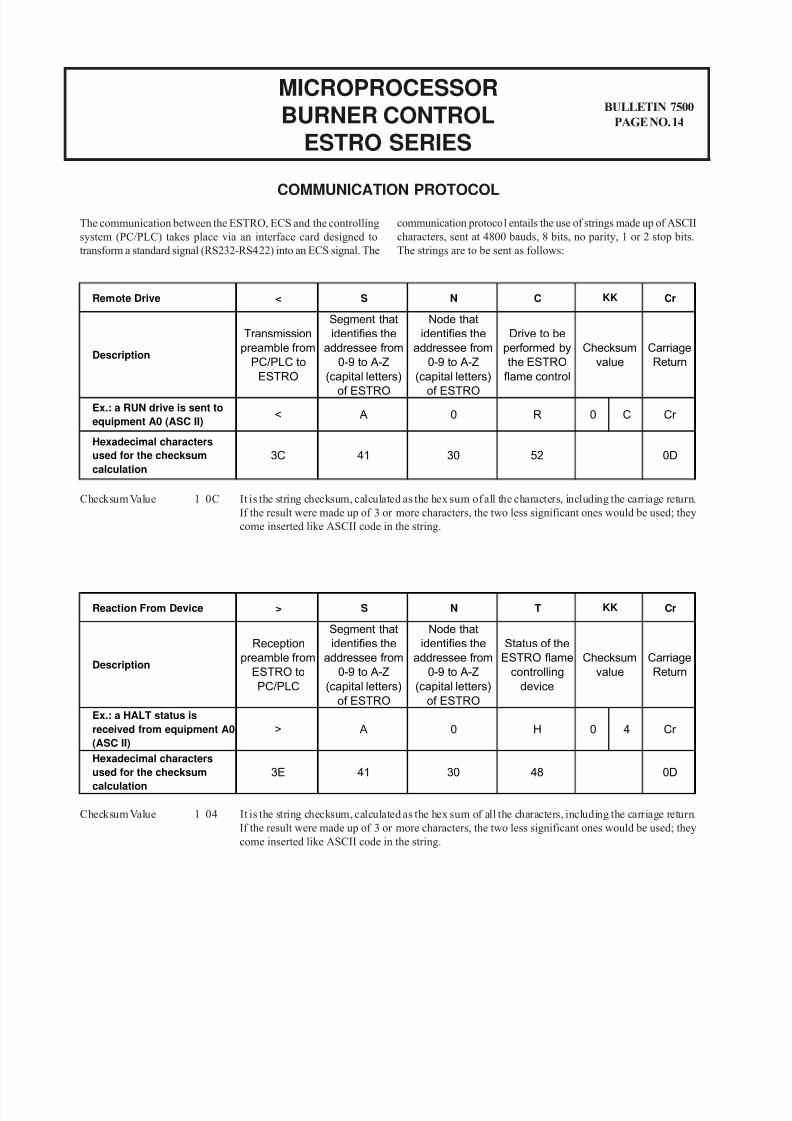
The communication between the ESTRO, ECS and the controlling
system (PC/PLC) takes place via an interface card designed to
transform a standard signal (RS232-RS422) into an ECS signal. The
COMMUNICATION PROTOCOL
communication protocol entails the use of strings made up of ASCII
characters, sent at 4800 bauds, 8 bits, no parity, 1 or 2 stop bits.
The strings are to be sent as follows:
Checksum Value 1 0C It is the string checksum, calculated as the hex sum of all the characters, including the carriage return.
If the result were made up of 3 or more characters, the two less significant ones would be used; they
come inserted like ASCII code in the string.
Checksum Value 1 04 It is the string checksum, calculated as the hex sum of all the characters, including the carriage return.
If the result were made up of 3 or more characters, the two less significant ones would be used; they
come inserted like ASCII code in the string.
Remote Drive < S N C Cr
Segment that
identifies the
addressee from
0-9 to A-Z
(capital letters)
of ESTRO
Node that
identifies the
addressee from
0-9 to A-Z
(capital letters)
of ESTRO
Carriage
Return
Ex.: a RUN drive is sent to
equipment A0 (ASC II)< A 0 R C Cr
Transmission
preamble from
PC/PLC to
ESTRO
Description
0D
Hexadecimal characters
used for the checksum
calculation
3C 41
0
Checksum
value
KK
30 52
Drive to be
performed by
the ESTRO
flame control
Reaction From Device > S N T Cr
48 0D
Hexadecimal characters
used for the checksumcalculation
3E 41 30
Carriage
Return
Ex.: a HALT status is
received from equipment A0
(ASC II)
> A 0 H 0 4 Cr
KK
Description
Reception
preamble from
ESTRO to
PC/PLC
Segment that
identifies the
addressee from
0-9 to A-Z
(capital letters)
of ESTRO
Node that
identifies the
addressee from
0-9 to A-Z
(capital letters)
of ESTRO
Status of the
ESTRO flame
controlling
device
Checksum
value
8/8/2019 Estro Burner Control
http://slidepdf.com/reader/full/estro-burner-control 15/18
CAUTION: Operation of combustion equip-ment can be hazardous resulting in bodily in-jury or equipment damage. Each burner shouldbe supervised by a combustion safeguard and
only qualified personnel should install, makesystem adjustments and perform any requiredservice.
NOTICE: PYRONICS practices apolicy of continuous improvement inthe design of its products. It reservesthe right to change the specifcations
at any time without prior notice.
BULLETIN 7500
PAGE NO. 15
MICROPROCESSORBURNER CONTROL
ESTRO SERIES
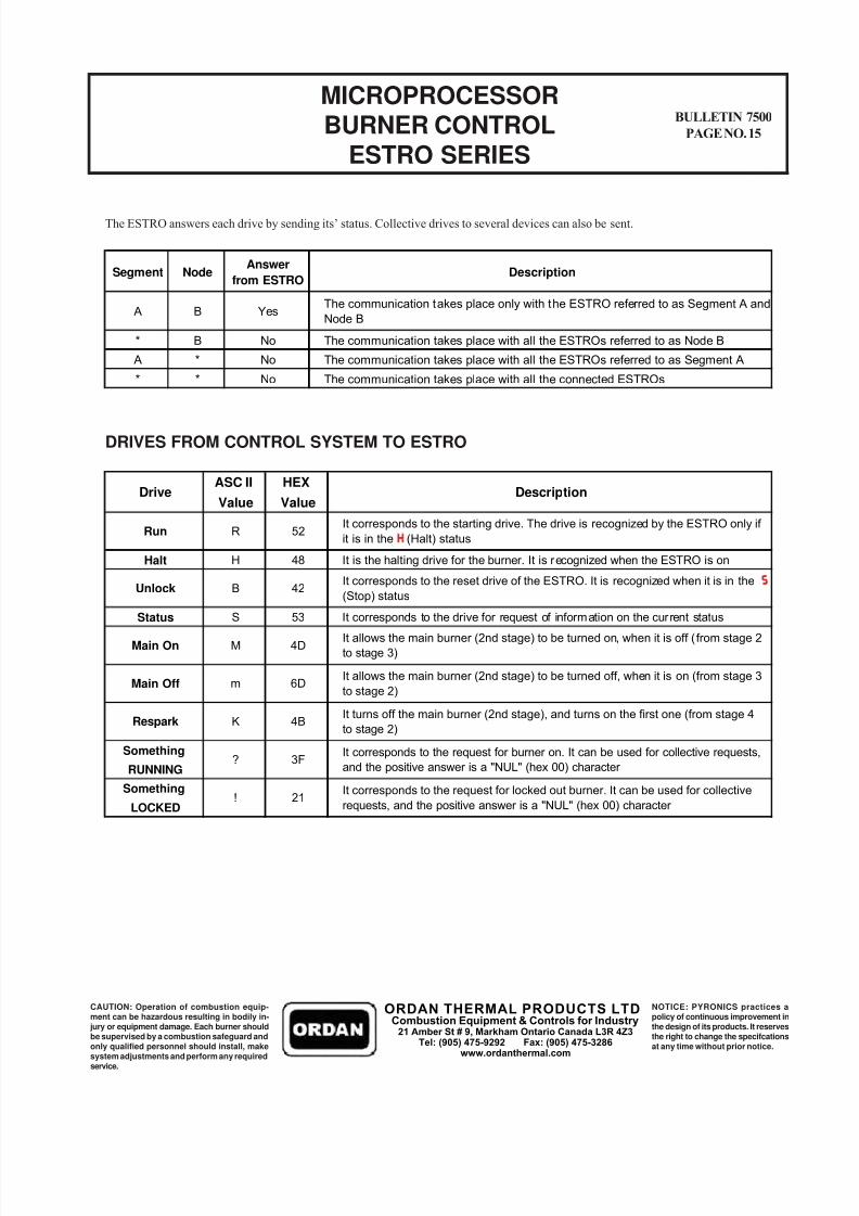
The ESTRO answers each drive by sending its’ status. Collective drives to several devices can also be sent.
DRIVES FROM CONTROL SYSTEM TO ESTRO
Segment NodeAnswer
from ESTRODescription
* B No The communication takes place with all the ESTROs referred to as Node B
A * No The communication takes place with all the ESTROs referred to as Segment A
* * No The communication takes place with all the connected ESTROs
The communication takes place only with the ESTRO referred to as Segment A and
Node BA B Yes
ASC II HEX
Value Value
Halt H 48 It is the halting drive for the burner. It is recognized when the ESTRO is on
Status S 53 It corresponds to the drive for request of information on the current status
Something
RUNNING
Something
LOCKED
It allows the main burner (2nd stage) to be turned on, when it is off ( from stage 2
to stage 3)4DMMain On
It allows the main burner (2nd stage) to be turned off, when it is on (from stage 3
to stage 2)6DmMain Off
It turns off the main burner (2nd stage), and turns on the first one (from stage 4
to stage 2)4BKRespark
? 3FIt corresponds to the request for burner on. It can be used for collective requests,
and the positive answer is a "NUL" (hex 00) character
! 21It corresponds to the request for locked out burner. It can be used for collective
requests, and the positive answer is a "NUL" (hex 00) character
Drive Description
It corresponds to the starting drive. The drive is recognized by the ESTRO only if
it is in the (Halt) status
It corresponds to the reset drive of the ESTRO. It is recognized when it is in the
(Stop) statusUnlock B 42
Run R 52
ORDAN THERMAL PRODUCTS LTDCombustion Equipment & Controls for Industry
21 Amber St # 9, Markham Ontario Canada L3R 4Z3Tel: (905) 475-9292 Fax: (905) 475-3286
www.ordanthermal.com
8/8/2019 Estro Burner Control
http://slidepdf.com/reader/full/estro-burner-control 16/18
MICROPROCESSORBURNER CONTROL
ESTRO SERIES
BULLETIN 7500
PAGE NO. 16
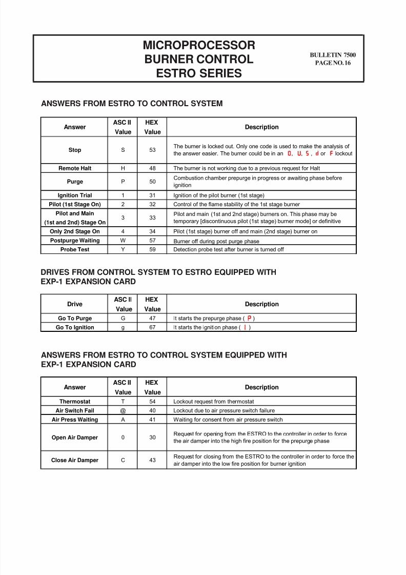
ANSWERS FROM ESTRO TO CONTROL SYSTEM
DRIVES FROM CONTROL SYSTEM TO ESTRO EQUIPPED WITHEXP-1 EXPANSION CARD
ANSWERS FROM ESTRO TO CONTROL SYSTEM EQUIPPED WITHEXP-1 EXPANSION CARD
ASC II HEX
Value Value
Go To Purge G 47 It starts the prepurge phase ( )
Go To Ignition g 67 It starts the ignition phase ( )
Drive Description
ASC II HEX
Value Value
Thermostat T 54 Lockout request from thermostat
Air Switch Fail @ 40 Lockout due to air pressure switch failure
Air Press Waiting A 41 Waiting for consent from air pressure switch
Answer Description
Open Air Damper
Close Air Damper C 43Request for closing from the ESTRO to the controller in order to force the
air damper into the low fire position for burner ignition
Request for opening from the ESTRO to the controller in order to force
the air damper into the high fire position for the prepurge phase300
ASC II HEX
Value Value
Remote Halt H 48 The burner is not working due to a previous request for Halt
Ignition Trial1 31 Ignition of the pilot burner (1st stage)
Pilot (1st Stage On) 2 32 Control of the flame stability of the 1st stage burner
Pilot and Main
(1st and 2nd) Stage On
Only 2nd Stage On 4 34 Pilot (1st stage) burner off and main (2nd stage) burner on
Postpurge Waiting W 57 Burner off during post purge phase
Probe Test Y 59 Detection probe test after burner is turned off
50PPurge
Answer Description
Pilot and main (1st and 2nd stage) burners on. This phase may be
temporary [discontinuous pilot (1st stage) burner mode] or definitive3 33
StopThe burner is locked out. Only one code is used to make the analysis of
the answer easier. The burner could be in an , , , or lockoutS 53
Combustion chamber prepurge in progress or awaiting phase before
ignition
8/8/2019 Estro Burner Control
http://slidepdf.com/reader/full/estro-burner-control 17/18
CAUTION: Operation of combustion equip-ment can be hazardous resulting in bodily in-jury or equipment damage. Each burner shouldbe supervised by a combustion safeguard and
only qualified personnel should install, makesystem adjustments and perform any requiredservice.
NOTICE: PYRONICS practices apolicy of continuous improvement inthe design of its products. It reservesthe right to change the specifcations
at any time without prior notice.
BULLETIN 7500
PAGE NO. 17
MICROPROCESSORBURNER CONTROL
ESTRO SERIES
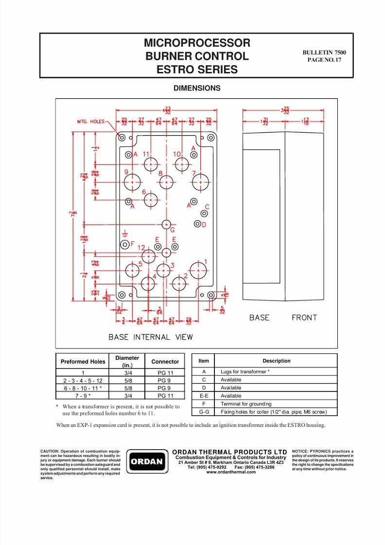
DIMENSIONS
* When a transformer is present, it is not possible to
use the preformed holes number 6 to 11.
When an EXP-1 expansion card is present, it is not possible to include an ignition transformer inside the ESTRO housing.
Preformed HolesDiameter
(in.)Connector
1 3/4 PG 11
2 - 3 - 4 - 5 - 12 5/8 PG 9
6 - 8 - 10 - 11 * 5/8 PG 9
7 - 9 * 3/4 PG 11
Item Description
A Lugs for transformer *
C Available
D Available
E-E Available
F Terminal for grounding
G-G Fixing holes for collar (1/2" dia. pipe, M6 screw)
ORDAN THERMAL PRODUCTS LTDCombustion Equipment & Controls for Industry
21 Amber St # 9, Markham Ontario Canada L3R 4Z3Tel: (905) 475-9292 Fax: (905) 475-3286
www.ordanthermal.com
8/8/2019 Estro Burner Control
http://slidepdf.com/reader/full/estro-burner-control 18/18
MICROPROCESSOR
BURNER CONTROLESTRO SERIES
BULLETIN 7500
PAGE NO. 18
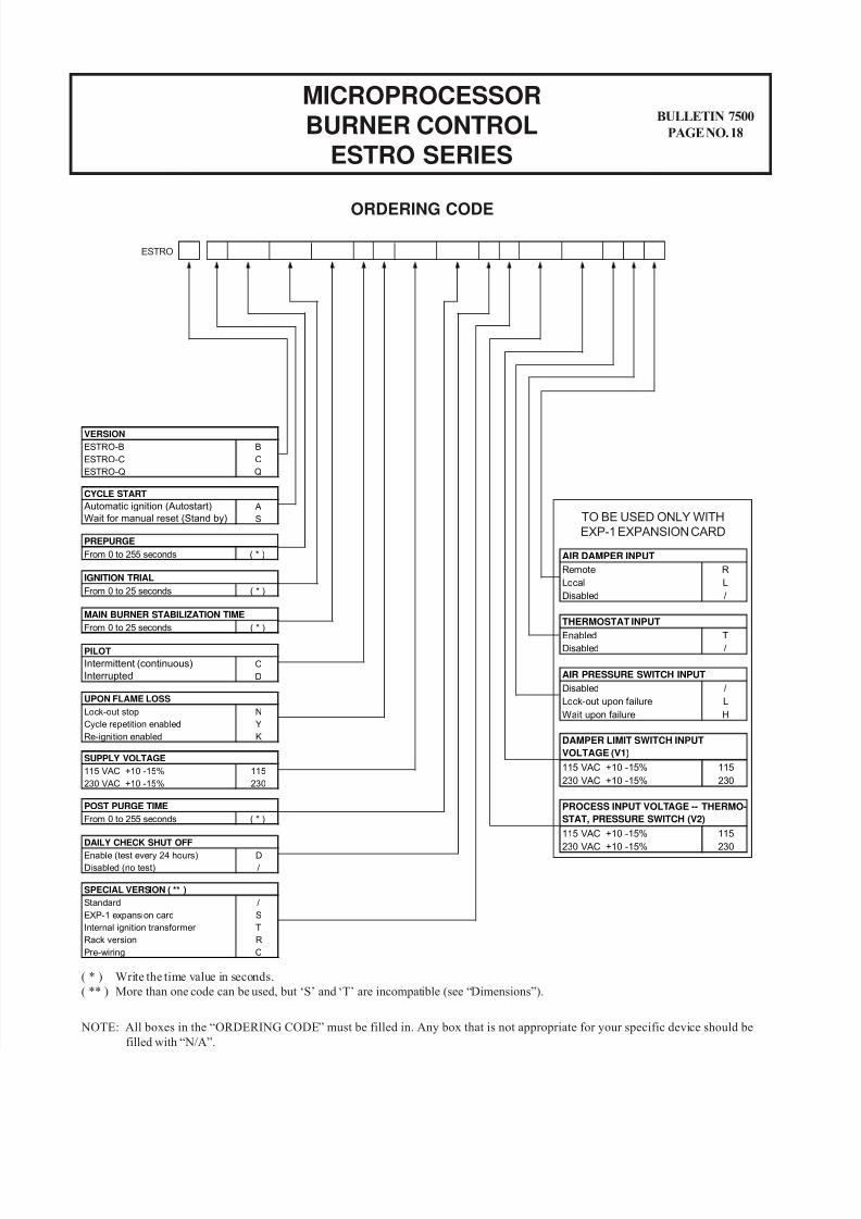
ORDERING CODE
ESTRO-B B
ESTRO-C C
ESTRO-Q Q
VERSION
Automatic ignition (Autostart) A
Wait for manual reset (Stand by) S
CYCLE START
From 0 to 255 seconds ( * )
PREPURGE
From 0 to 25 seconds ( * )
MAIN BURNER STABILIZATION TIME
Lock-out stop N
Cycle repetition enabled Y
Re-ignition enabled K
UPON FLAME LOSS
115 VAC +10 -15% 115
230 VAC +10 -15% 230
SUPPLY VOLTAGE
From 0 to 255 seconds ( * )
POST PURGE TIME
115 VAC +10 -15% 115
230 VAC +10 -15% 230
DAMPER LIMIT SWITCH INPUT
VOLTAGE (V1)
115 VAC +10 -15% 115
230 VAC +10 -15% 230
PROCESS INPUT VOLTAGE -- THERMO-
STAT, PRESSURE SWITCH (V2)
ESTRO
TO BE USED ONLY WITH
EXP-1 EXPANSION CARD
( * ) Write the time value in seconds.
( ** ) More than one code can be used, but ‘S’ and ‘T’ are incompatible (see “Dimensions”).
From 0 to 25 seconds ( * )
IGNITION TRIAL
Intermittent (continuous) C
Interrupted D
PILOT
Enable (test every 24 hours) D
Disabled (no test) /
DAILY CHECK SHUT OFF
Standard /
EXP-1 expansion card S
Internal ignition transformer T
Rack version R
Pre-wiring C
SPECIAL VERSION ( ** )
Remote R
Local L
Disabled /
AIR DAMPER INPUT
Enabled T
Disabled /
THERMOSTAT INPUT
Disabled /
Lock-out upon failure L
Wait upon failure H
AIR PRESSURE SWITCH INPUT
NOTE: All boxes in the “ORDERING CODE” must be filled in. Any box that is not appropriate for your specific device should be
filled with “N/A”.
Recommended