Technical and Test Institute for Construction Prague Prosecká 811/76a 190 00 Prague Czech Republic [email protected]
Member of
www.eota.eu
ETA 17/0376 of 13/07/2017 – Page 1 of 56 090-039017
European Technical Assessment
ETA 17/0376 of 13/07/2017
(English language translation, the original version in Czech language) Technical Assessment Body issuing the ETA: Technical and Test Institute for Construction Prague Trade name of the construction product Fix Master FIT-Pe 270
Fix Master FIT-Px 270 Fix Master FIT-Pt 270
Product family to which the construction product belongs
Product area code: 33 Injection anchors for use in masonry
Manufacturer
Ferrometal Oy Karhutie 9 Fl-01900 Nurmijärvi Finland
Manufacturing plant(s) Plant 1, Finland
This European Technical Assessment contains
56 pages including 52 Annexes which form an integral part of this assessment.
This European Technical Assessment is issued in accordance with regulation (EU) No 305/2011, on the basis of
ETAG 029, edition 2013, used as European Assessment Document (EAD)
Translations of this European Technical Assessment in other languages shall fully correspond to the original issued document and should be identified as such. Communication of this European Technical Assessment, including transmission by electronic means, shall be in full (excepted the confidential Annex(es) referred to above). However, partial reproduction may be made, with the written consent of the issuing Technical Assessment Body. Any partial reproduction has to be identified as such.
Page 2/56 of ETA 17/0376, issued of 13/07/2017 English translation by TZÚS Prague – branch TIS
1. Technical description of the product
The Fix Master FIT-Pe 270, FIT-Px 270, FIT-Pt 270 polyester resin styrene-free for masonry is bonded anchor consisting of a cartridge with injection mortar, a steel element and a plastic sleeve. The steel elements are the commercial threaded rods with hexagon nut and washer. The steel elements are made of galvanized or zinc plated steel, stainless or high corrosion resistance steel. The anchor is placed into a drilled hole filled with injection mortar. The steel element is anchored via the bond between metal part, injection mortar and masonry. The illustration and the description of the product are given in Annex A.
2. Specification of the intended use in accordance wit h the applicable EAD
The performances given in Section 3 are only valid if the anchor is used in compliance with the specifications and conditions given in Annex B.
The provisions made in this European Technical Assessment are based on an assumed working life of the anchor of 50 years. The indications given on the working life cannot be interpreted as a guarantee given by the producer, but are to be regarded only as a means for choosing the products in relation to the expected economically reasonable working life of the works.
3. Performance of the product and references to the me thods used for its assessment
3.1 Mechanical resistance and stability (BWR 1)
Essential characteristic Performance Reduction factor for job site tests (β – factor) See Annex C 1 Characteristic resistance for tension and shear loads See Annex C 5 to C 39 Characteristic resistance for bending moments See Annex C 2 Displacement under shear and tension loads See Annex C 5 to C 38 Edge distances and spacing See Annex C 4 to C 38
3.2 Safety in case of fire (BWR 2)
Essential characteristic Performance Reaction to fire Anchorages satisfy
requirements for Class A1 Resistance to fire No performance assessed
3.3 Hygiene, health and environment (BWR 3)
Regarding dangerous substances contained in this European Technical Assessment, there may be requirements applicable to the products falling within its scope (e.g. transposed European legislation and national laws, regulations and administrative provisions). In order to meet the provisions of the Regulation (EU) No 305/2011), these requirements need also to be complied with, when and where they apply.
3.4 Safety in use (BWR 4)
For basic requirement safety in use the same criteria are valid as for Basic Requirement Mechanical resistance and stability.
3.5 Sustainable use of natural resources (BWR 7)
For the sustainable use of natural resources no performance was determined for this product.
Page 3/56 of ETA 17/0376, issued of 13/07/2017 English translation by TZÚS Prague – branch TIS
3.6 General aspects relating to fitness for use
Durability and serviceability are only ensured if the specifications of intended use according to Annex B 1 are taken into account.
4. Assessment and verification of constancy of perf ormance (AVCP) system
applied with reference to its legal base
According to the Decision 97/177/EC of the European Commission1 the system of assessment verification of constancy of performance (see Annex V to Regulation (EU) No 305/2011) given in the following table applies.
Product Intended use Level or class
System
Injection anchors for use in masonry
For fixing and/or supporting to masonry, structural elements (which contributes to the stability of the construction works) or heavy units
- 1
5. Technical details necessary for the implementati on of the AVCP system, as
provided in the applicable EAD 5.1 Tasks of the manufacturer
The manufacturer shall exercise permanent internal control of production. All the elements, requirements and provisions adopted by the manufacturer shall be documented in a systematic manner in the form of written policies and procedures, including records of results performed. This production control system shall insure that the product is in conformity with this European Technical Assessment. The manufacturer may only use raw materials stated in the technical documentation of this European Technical Assessment.
The factory production control shall be in accordance with the control plan which is a part of the technical documentation of this European Technical Assessment. The control plan is laid down in the context of the factory production control system operated by the manufacturer and deposited at Technical and Test Institute for Construction Prague 2 The results of factory production control shall be recorded and evaluated in accordance with the provisions of the control plan.
The manufacturer shall, on the basis of a contract, involve a body which is notified for the tasks referred to in section 4 in the field of anchors in order to undertake the actions laid down in section 5.2. For this purpose, the control plan referred to in this section and section 5.2 shall be handed over by the manufacturer to the notified body involved.
The manufacturer shall make a declaration of conformity, stating that the construction product is in conformity with the provisions of this European Technical Assessment.
1 Official Journal of the European Communities L 073 of 14.03.1997 2 The control plan is a confidential part of the documentation of the European technical assessment, but not published
together with the ETA and only handed over to the approved body involved in the procedure of AVCP.
Page 4/56 of ETA 17/0376, issued of 13/07/2017 English translation by TZÚS Prague – branch TIS
5.2 Tasks of the notified bodies
The notified body shall retain the essential points of its actions referred to above and state the results obtained and conclusions drawn in a written report.
The notified certification body involved by the manufacturer shall issue a certificate of constancy of performance of the product stating the conformity with the provisions of this European Technical Assessment. In cases where the provisions of the European Technical Assessment and its control plan are no longer fulfilled the notified body shall withdraw the certificate of constancy of performance and inform Technical and Test Institute for Construction Prague without delay.
Issued in Prague on 13.07.2017
By
Ing. Mária Schaan Head of the TAB

Page 5/56 of ETA 17/0376, issued of 13/07/2017 English translation by TZÚS Prague – branch TIS
Installation in hollow brick; threaded rod with sle eve
Installation in solid brick; threaded rod with slee ve
Installation in solid brick; threaded rod without s leeve
h = thickness of member d0 = nominal drill hole diameter h0 = depth of drill hole at shoulder tfix = thickness of fixture hef = effective anchorage depth Tinst,max = max installation torque moment hnom = overall embedment depth
Ferrometal Injection System for masonry Fix Master FIT-Pe 270, Fix Master FIT-Px 270, Fix M aster FIT-Pt 270
Annex A 1 Product description Installed condition
Page 6/56 of ETA 17/0376, issued of 13/07/2017 English translation by TZÚS Prague – branch TIS
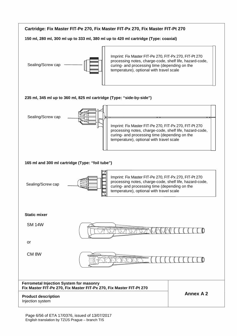
Cartridge: Fix Master FIT-Pe 270, Fix Master FIT-Px 270, Fix Master FIT-Pt 270 150 ml, 280 ml, 300 ml up to 333 ml, 380 ml up to 4 20 ml cartridge (Type: coaxial)
235 ml, 345 ml up to 360 ml, 825 ml cartridge (Type : “side-by-side”)
165 ml and 300 ml cartridge (Type: “foil tube”)
Static mixer
SM 14W
or
CM 8W
Ferrometal Injection System for masonry Fix Master FIT-Pe 270, Fix Master FIT-Px 270, Fix M aster FIT-Pt 270
Annex A 2 Product description Injection system
Imprint: Fix Master FIT-Pe 270, FIT-Px 270, FIT-Pt 270 processing notes, charge-code, shelf life, hazard-code, curing- and processing time (depending on the temperature), optional with travel scale
Sealing/Screw cap
Sealing/Screw cap
Sealing/Screw cap
Imprint: Fix Master FIT-Pe 270, FIT-Px 270, FIT-Pt 270 processing notes, charge-code, shelf life, hazard-code, curing- and processing time (depending on the temperature), optional with travel scale
Imprint: Fix Master FIT-Pe 270, FIT-Px 270, FIT-Pt 270 processing notes, charge-code, shelf life, hazard-code, curing- and processing time (depending on the temperature), optional with travel scale
Page 7/56 of ETA 17/0376, issued of 13/07/2017 English translation by TZÚS Prague – branch TIS
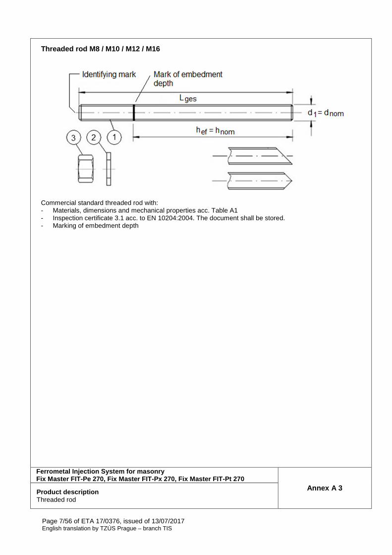
Threaded rod M8 / M10 / M12 / M16
Commercial standard threaded rod with: - Materials, dimensions and mechanical properties acc. Table A1 - Inspection certificate 3.1 acc. to EN 10204:2004. The document shall be stored. - Marking of embedment depth
Ferrometal Injection System for masonry Fix Master FIT-Pe 270, Fix Master FIT-Px 270, Fix M aster FIT-Pt 270
Annex A 3 Product description Threaded rod
Page 8/56 of ETA 17/0376, issued of 13/07/2017 English translation by TZÚS Prague – branch TIS
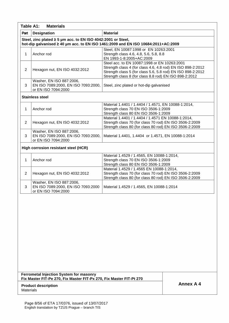
Table A1: Materials
Part Designation Material
Steel, zinc plated ≥ 5 µm acc. to EN ISO 4042:2001 or Steel, hot-dip galvanised ≥ 40 µm acc. to EN ISO 1461:2009 and EN ISO 10684:20 11+AC:2009
1 Anchor rod Steel, EN 10087:1998 or EN 10263:2001 Strength class 4.6, 4.8, 5.6, 5.8, 8.8 EN 1993-1-8:2005+AC:2009
2 Hexagon nut, EN ISO 4032:2012
Steel acc. to EN 10087:1998 or EN 10263:2001 Strength class 4 (for class 4.6, 4.8 rod) EN ISO 898-2:2012 Strength class 5 (for class 5.6, 5.8 rod) EN ISO 898-2:2012 Strength class 8 (for class 8.8 rod) EN ISO 898-2:2012
3 Washer, EN ISO 887:2006, EN ISO 7089:2000, EN ISO 7093:2000, or EN ISO 7094:2000
Steel, zinc plated or hot-dip galvanised
Stainless steel
1 Anchor rod Material 1.4401 / 1.4404 / 1.4571, EN 10088-1:2014, Strength class 70 EN ISO 3506-1:2009 Strength class 80 EN ISO 3506-1:2009
2 Hexagon nut, EN ISO 4032:2012 Material 1.4401 / 1.4404 / 1.4571 EN 10088-1:2014, Strength class 70 (for class 70 rod) EN ISO 3506-2:2009 Strength class 80 (for class 80 rod) EN ISO 3506-2:2009
3 Washer, EN ISO 887:2006, EN ISO 7089:2000, EN ISO 7093:2000, or EN ISO 7094:2000
Material 1.4401, 1.4404 or 1.4571, EN 10088-1:2014
High corrosion resistant steel (HCR)
1 Anchor rod Material 1.4529 / 1.4565, EN 10088-1:2014, Strength class 70 EN ISO 3506-1:2009 Strength class 80 EN ISO 3506-1:2009
2 Hexagon nut, EN ISO 4032:2012 Material 1.4529 / 1.4565 EN 10088-1:2014, Strength class 70 (for class 70 rod) EN ISO 3506-2:2009 Strength class 80 (for class 80 rod) EN ISO 3506-2:2009
3 Washer, EN ISO 887:2006, EN ISO 7089:2000, EN ISO 7093:2000 or EN ISO 7094:2000
Material 1.4529 / 1.4565, EN 10088-1:2014
Ferrometal Injection System for masonry Fix Master FIT-Pe 270, Fix Master FIT-Px 270, Fix M aster FIT-Pt 270
Annex A 4 Product description Materials

Page 9/56 of ETA 17/0376, issued of 13/07/2017 English translation by TZÚS Prague – branch TIS
Sleeve (Plastic)
SH 12x80 SH 16x85 SH 20x85
SH 16x130 SH 20x130 SH 20x200
SH 16x130/330
Table A2: Sleeve sizes (mm)
Sleeve Size ds ls hef = hnom
[mm] [mm] [mm] SH12x80 12 80 80 SH16x85 16 85 85 SH16x130 16 130 130
SH16x130/330 16 330 130 SH20x85 20 85 85 SH20x130 20 130 130 SH20x200 20 200 200
Ferrometal Injection System for masonry Fix Master FIT-Pe 270, Fix Master FIT-Px 270, Fix M aster FIT-Pt 270
Annex A 5 Product description Sleeves
ls = hef = hnom
ds
ds
ls = hef = hnom
Page 10/56 of ETA 17/0376, issued of 13/07/2017 English translation by TZÚS Prague – branch TIS
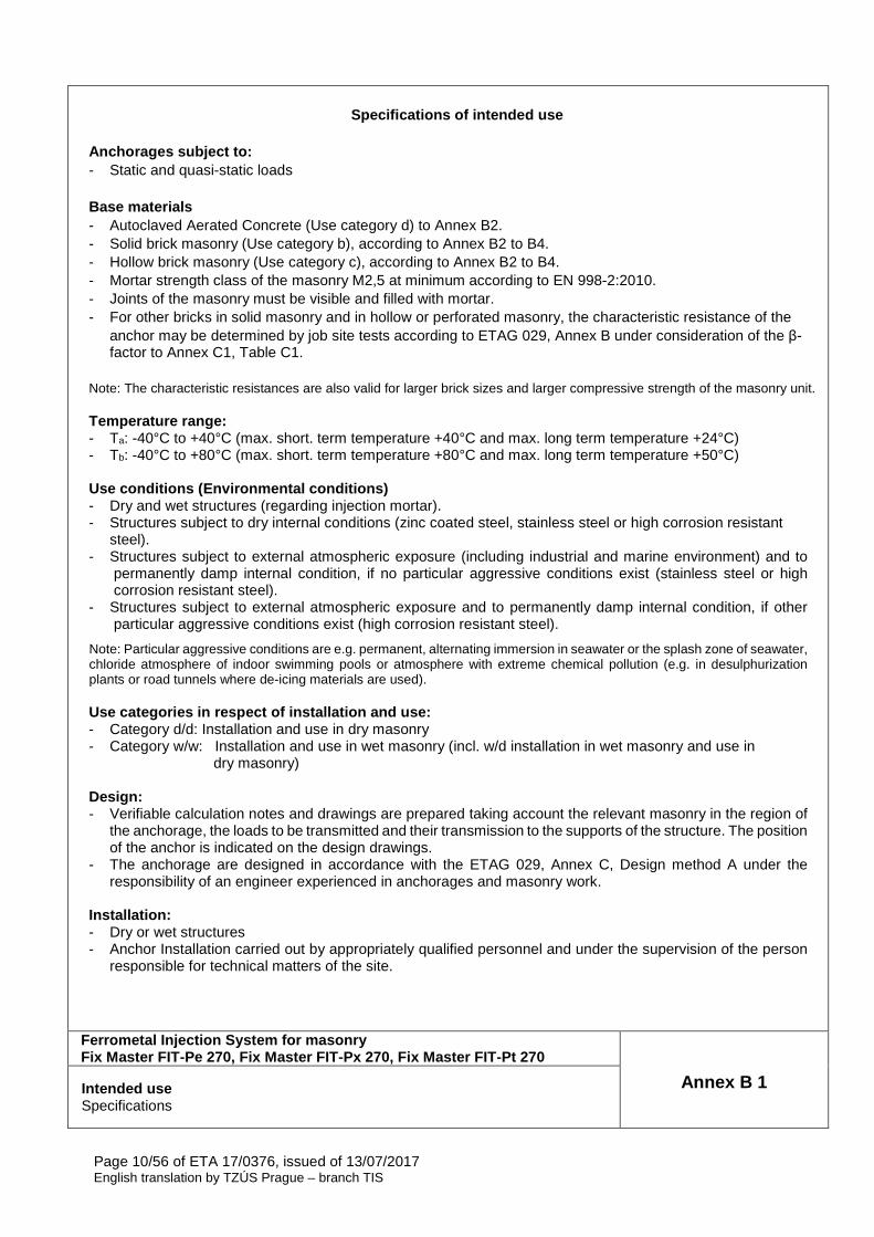
Specifications of intended use
Anchorages subject to: - Static and quasi-static loads Base materials - Autoclaved Aerated Concrete (Use category d) to Annex B2. - Solid brick masonry (Use category b), according to Annex B2 to B4. - Hollow brick masonry (Use category c), according to Annex B2 to B4. - Mortar strength class of the masonry M2,5 at minimum according to EN 998-2:2010. - Joints of the masonry must be visible and filled with mortar. - For other bricks in solid masonry and in hollow or perforated masonry, the characteristic resistance of the
anchor may be determined by job site tests according to ETAG 029, Annex B under consideration of the β-factor to Annex C1, Table C1.
Note: The characteristic resistances are also valid for larger brick sizes and larger compressive strength of the masonry unit. Temperature range: - Ta: -40°C to +40°C (max. short. term temperature +40°C and max. long term temperature +24°C) - Tb: -40°C to +80°C (max. short. term temperature +80°C and max. long term temperature +50°C) Use conditions (Environmental conditions) - Dry and wet structures (regarding injection mortar). - Structures subject to dry internal conditions (zinc coated steel, stainless steel or high corrosion resistant
steel). - Structures subject to external atmospheric exposure (including industrial and marine environment) and to
permanently damp internal condition, if no particular aggressive conditions exist (stainless steel or high corrosion resistant steel).
- Structures subject to external atmospheric exposure and to permanently damp internal condition, if other particular aggressive conditions exist (high corrosion resistant steel).
Note: Particular aggressive conditions are e.g. permanent, alternating immersion in seawater or the splash zone of seawater, chloride atmosphere of indoor swimming pools or atmosphere with extreme chemical pollution (e.g. in desulphurization plants or road tunnels where de-icing materials are used).
Use categories in respect of installation and use: - Category d/d: Installation and use in dry masonry - Category w/w: Installation and use in wet masonry (incl. w/d installation in wet masonry and use in
dry masonry)
Design: - Verifiable calculation notes and drawings are prepared taking account the relevant masonry in the region of
the anchorage, the loads to be transmitted and their transmission to the supports of the structure. The position of the anchor is indicated on the design drawings.
- The anchorage are designed in accordance with the ETAG 029, Annex C, Design method A under the responsibility of an engineer experienced in anchorages and masonry work.
Installation: - Dry or wet structures - Anchor Installation carried out by appropriately qualified personnel and under the supervision of the person
responsible for technical matters of the site.
Ferrometal Injection System for masonry Fix Master FIT-Pe 270, Fix Master FIT-Px 270, Fix M aster FIT-Pt 270
Annex B 1 Intended use Specifications
Page 11/56 of ETA 17/0376, issued of 13/07/2017 English translation by TZÚS Prague – branch TIS
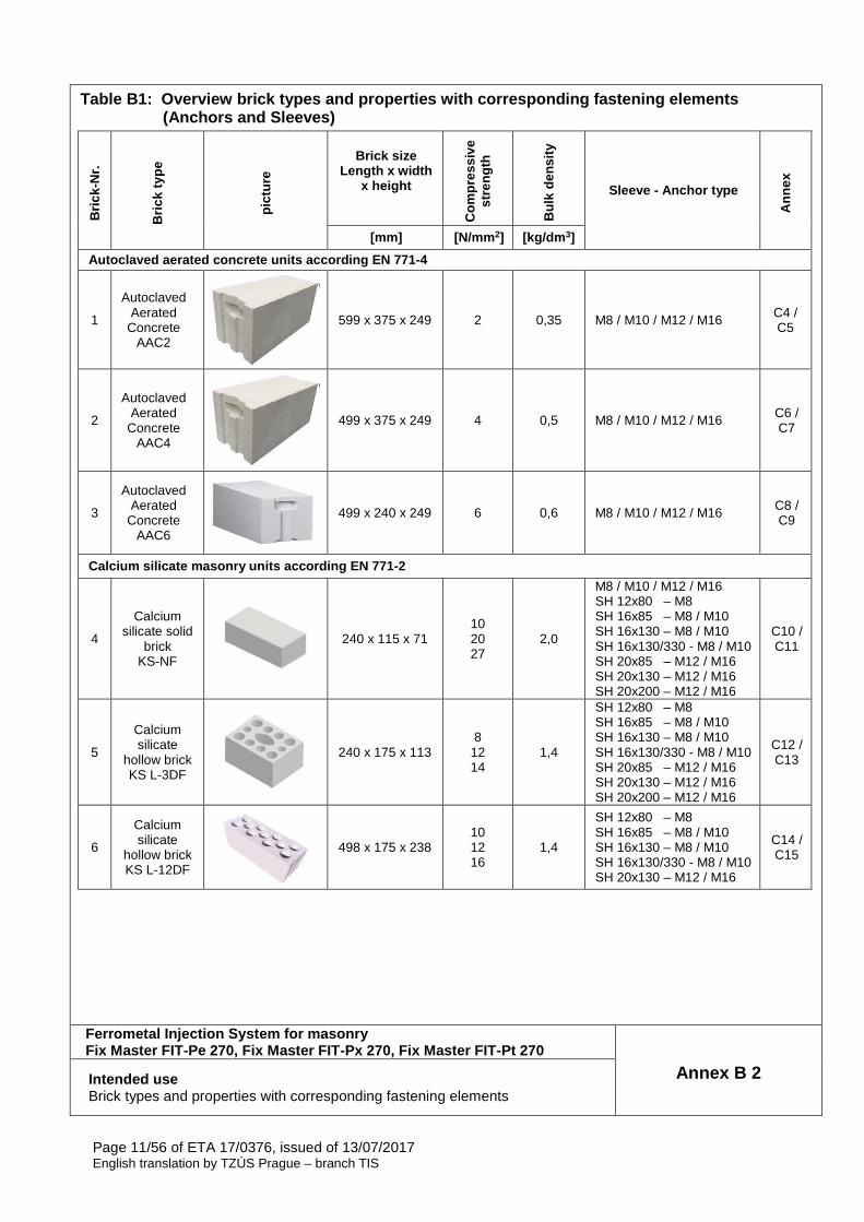
Table B1: Overview brick types and properties with corresponding fastening elements (Anchors and Sleeves)
Bric
k-N
r.
Bric
k ty
pe
pict
ure
Brick size Length x width
x height
Com
pres
sive
st
reng
th
Bul
k de
nsity
Sleeve - Anchor type
Ann
ex
[mm] [N/mm 2] [kg/dm 3]
Autoclaved aerated concrete units according EN 771-4
1
Autoclaved Aerated
Concrete AAC2
599 x 375 x 249 2 0,35 M8 / M10 / M12 / M16 C4 / C5
2
Autoclaved Aerated
Concrete AAC4
499 x 375 x 249 4 0,5 M8 / M10 / M12 / M16 C6 / C7
3
Autoclaved Aerated
Concrete AAC6
499 x 240 x 249 6 0,6 M8 / M10 / M12 / M16 C8 / C9
Calcium silicate masonry units according EN 771-2
4
Calcium silicate solid
brick KS-NF
240 x 115 x 71 10 20 27
2,0
M8 / M10 / M12 / M16 SH 12x80 – M8 SH 16x85 – M8 / M10 SH 16x130 – M8 / M10 SH 16x130/330 - M8 / M10 SH 20x85 – M12 / M16 SH 20x130 – M12 / M16 SH 20x200 – M12 / M16
C10 / C11
5
Calcium silicate
hollow brick KS L-3DF
240 x 175 x 113 8
12 14
1,4
SH 12x80 – M8 SH 16x85 – M8 / M10 SH 16x130 – M8 / M10 SH 16x130/330 - M8 / M10 SH 20x85 – M12 / M16 SH 20x130 – M12 / M16 SH 20x200 – M12 / M16
C12 / C13
6
Calcium silicate
hollow brick KS L-12DF
498 x 175 x 238 10 12 16
1,4
SH 12x80 – M8 SH 16x85 – M8 / M10 SH 16x130 – M8 / M10 SH 16x130/330 - M8 / M10 SH 20x130 – M12 / M16
C14 / C15
Ferrometal Injection System for masonry Fix Master FIT-Pe 270, Fix Master FIT-Px 270, Fix M aster FIT-Pt 270
Annex B 2 Intended use Brick types and properties with corresponding fastening elements
Page 12/56 of ETA 17/0376, issued of 13/07/2017 English translation by TZÚS Prague – branch TIS
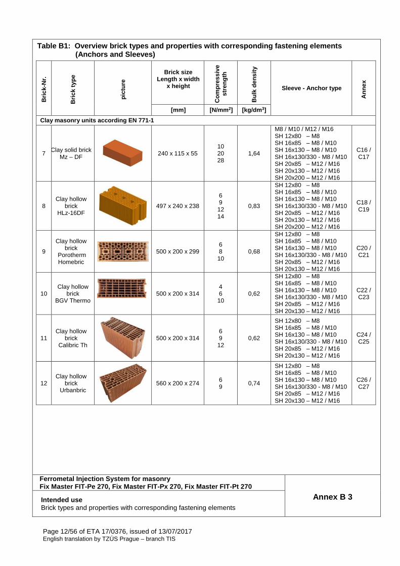
Table B1: Overview brick types and properties with corresponding fastening elements (Anchors and Sleeves)
Bric
k-N
r.
Bric
k ty
pe
pict
ure
Brick size Length x width
x height
Com
pres
sive
st
reng
th
Bul
k de
nsity
Sleeve - Anchor type
Ann
ex
[mm] [N/mm 2] [kg/dm 3]
Clay masonry units according EN 771-1
7 Clay solid brick
Mz – DF
240 x 115 x 55 10 20 28
1,64
M8 / M10 / M12 / M16 SH 12x80 – M8 SH 16x85 – M8 / M10 SH 16x130 – M8 / M10 SH 16x130/330 - M8 / M10 SH 20x85 – M12 / M16 SH 20x130 – M12 / M16 SH 20x200 – M12 / M16
C16 / C17
8 Clay hollow
brick HLz-16DF
497 x 240 x 238
6 9 12 14
0,83
SH 12x80 – M8 SH 16x85 – M8 / M10 SH 16x130 – M8 / M10 SH 16x130/330 - M8 / M10 SH 20x85 – M12 / M16 SH 20x130 – M12 / M16 SH 20x200 – M12 / M16
C18 / C19
9
Clay hollow brick
Porotherm Homebric
500 x 200 x 299 6 8 10
0,68
SH 12x80 – M8 SH 16x85 – M8 / M10 SH 16x130 – M8 / M10 SH 16x130/330 - M8 / M10 SH 20x85 – M12 / M16 SH 20x130 – M12 / M16
C20 / C21
10 Clay hollow
brick BGV Thermo
500 x 200 x 314 4 6 10
0,62
SH 12x80 – M8 SH 16x85 – M8 / M10 SH 16x130 – M8 / M10 SH 16x130/330 - M8 / M10 SH 20x85 – M12 / M16 SH 20x130 – M12 / M16
C22 / C23
11 Clay hollow
brick Calibric Th
500 x 200 x 314 6 9 12
0,62
SH 12x80 – M8 SH 16x85 – M8 / M10 SH 16x130 – M8 / M10 SH 16x130/330 - M8 / M10 SH 20x85 – M12 / M16 SH 20x130 – M12 / M16
C24 / C25
12 Clay hollow
brick Urbanbric
560 x 200 x 274 6 9 0,74
SH 12x80 – M8 SH 16x85 – M8 / M10 SH 16x130 – M8 / M10 SH 16x130/330 - M8 / M10 SH 20x85 – M12 / M16 SH 20x130 – M12 / M16
C26 / C27
Ferrometal Injection System for masonry Fix Master FIT-Pe 270, Fix Master FIT-Px 270, Fix M aster FIT-Pt 270
Annex B 3 Intended use Brick types and properties with corresponding fastening elements
Page 13/56 of ETA 17/0376, issued of 13/07/2017 English translation by TZÚS Prague – branch TIS
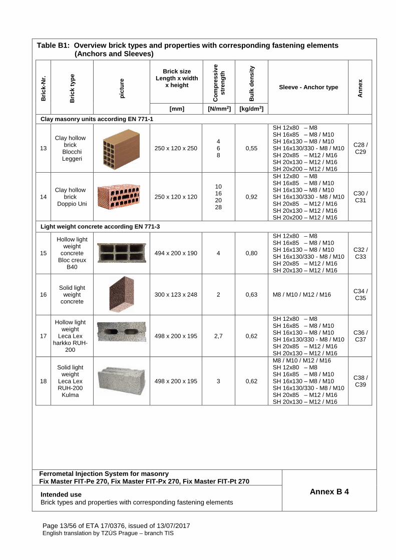
Table B1: Overview brick types and properties with corresponding fastening elements (Anchors and Sleeves)
Bric
k-N
r.
Bric
k ty
pe
pict
ure
Brick size Length x width
x height
Com
pres
sive
st
reng
th
Bul
k de
nsity
Sleeve - Anchor type
Ann
ex
[mm] [N/mm 2] [kg/dm 3]
Clay masonry units according EN 771-1
13
Clay hollow brick Blocchi Leggeri
250 x 120 x 250 4 6 8
0,55
SH 12x80 – M8 SH 16x85 – M8 / M10 SH 16x130 – M8 / M10 SH 16x130/330 - M8 / M10 SH 20x85 – M12 / M16 SH 20x130 – M12 / M16 SH 20x200 – M12 / M16
C28 / C29
14 Clay hollow
brick Doppio Uni
250 x 120 x 120
10 16 20 28
0,92
SH 12x80 – M8 SH 16x85 – M8 / M10 SH 16x130 – M8 / M10 SH 16x130/330 - M8 / M10 SH 20x85 – M12 / M16 SH 20x130 – M12 / M16 SH 20x200 – M12 / M16
C30 / C31
Light weight concrete according EN 771-3
15
Hollow light weight
concrete Bloc creux
B40
494 x 200 x 190 4 0,80
SH 12x80 – M8 SH 16x85 – M8 / M10 SH 16x130 – M8 / M10 SH 16x130/330 - M8 / M10 SH 20x85 – M12 / M16 SH 20x130 – M12 / M16
C32 / C33
16 Solid light
weight concrete
300 x 123 x 248 2 0,63 M8 / M10 / M12 / M16 C34 / C35
17
Hollow light weight
Leca Lex harkko RUH-
200
498 x 200 x 195 2,7 0,62
SH 12x80 – M8 SH 16x85 – M8 / M10 SH 16x130 – M8 / M10 SH 16x130/330 - M8 / M10 SH 20x85 – M12 / M16 SH 20x130 – M12 / M16
C36 / C37
18
Solid light weight
Leca Lex RUH-200
Kulma
498 x 200 x 195 3 0,62
M8 / M10 / M12 / M16 SH 12x80 – M8 SH 16x85 – M8 / M10 SH 16x130 – M8 / M10 SH 16x130/330 - M8 / M10 SH 20x85 – M12 / M16 SH 20x130 – M12 / M16
C38 / C39
Ferrometal Injection System for masonry Fix Master FIT-Pe 270, Fix Master FIT-Px 270, Fix M aster FIT-Pt 270
Annex B 4 Intended use Brick types and properties with corresponding fastening elements
Page 14/56 of ETA 17/0376, issued of 13/07/2017 English translation by TZÚS Prague – branch TIS
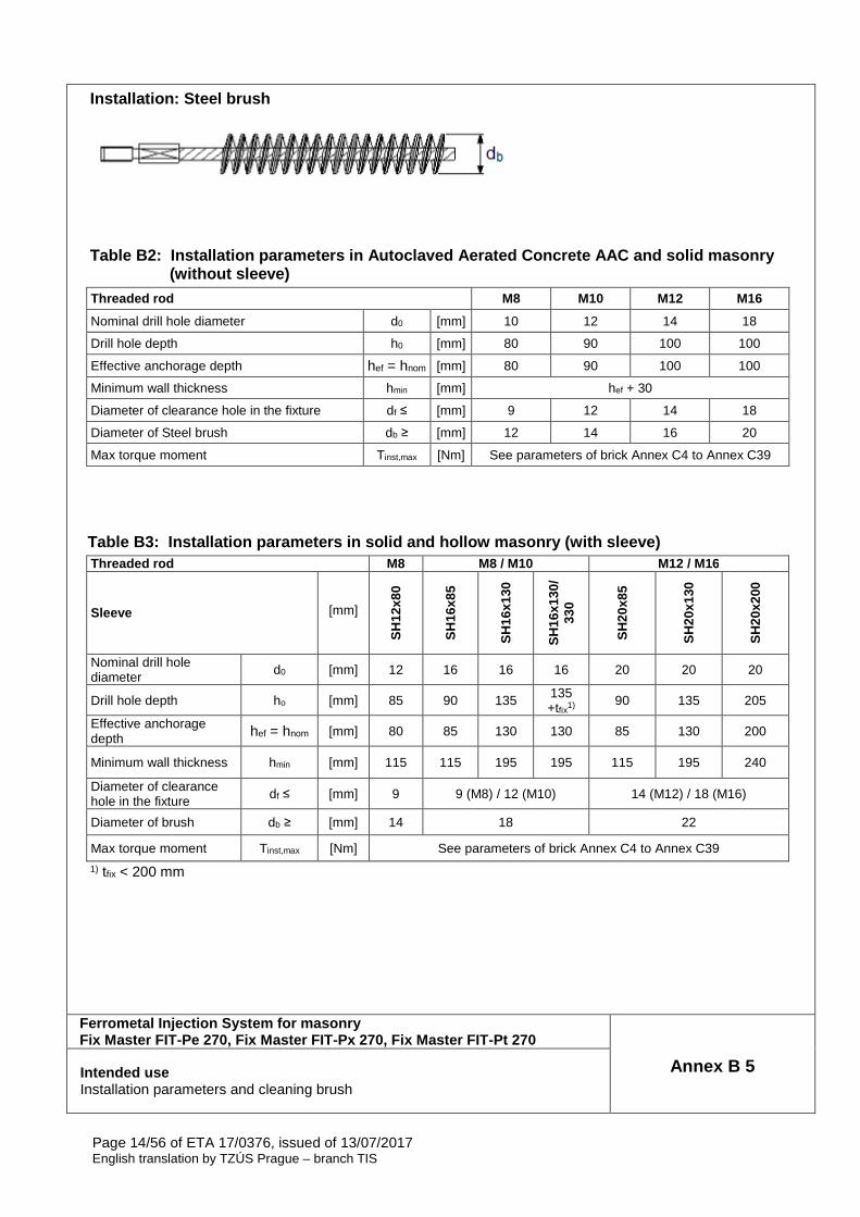
Installation: Steel brush
Table B2: Installation parameters in Autoclaved Aerated Concr ete AAC and solid masonry (without sleeve)
Threaded rod M8 M10 M12 M16
Nominal drill hole diameter d0 [mm] 10 12 14 18
Drill hole depth h0 [mm] 80 90 100 100
Effective anchorage depth hef = hnom [mm] 80 90 100 100
Minimum wall thickness hmin [mm] hef + 30
Diameter of clearance hole in the fixture df ≤ [mm] 9 12 14 18
Diameter of Steel brush db ≥ [mm] 12 14 16 20
Max torque moment Tinst,max [Nm] See parameters of brick Annex C4 to Annex C39
Table B3: Installation parameters in solid and hollow masonry (with sleeve) Threaded rod M8 M8 / M10 M12 / M16
Sleeve [mm]
SH
12x8
0
SH
16x8
5
SH
16x1
30
SH
16x1
30/
330
SH
20x8
5
SH
20x1
30
SH
20x2
00
Nominal drill hole diameter d0 [mm] 12 16 16 16 20 20 20
Drill hole depth ho [mm] 85 90 135 135 +tfix1) 90 135 205
Effective anchorage depth hef = hnom [mm] 80 85 130 130 85 130 200
Minimum wall thickness hmin [mm] 115 115 195 195 115 195 240
Diameter of clearance hole in the fixture df ≤ [mm] 9 9 (M8) / 12 (M10) 14 (M12) / 18 (M16)
Diameter of brush db ≥ [mm] 14 18 22
Max torque moment Tinst,max [Nm] See parameters of brick Annex C4 to Annex C39
1) tfix < 200 mm
Ferrometal Injection System for masonry Fix Master FIT-Pe 270, Fix Master FIT-Px 270, Fix M aster FIT-Pt 270
Annex B 5 Intended use Installation parameters and cleaning brush
Page 15/56 of ETA 17/0376, issued of 13/07/2017 English translation by TZÚS Prague – branch TIS
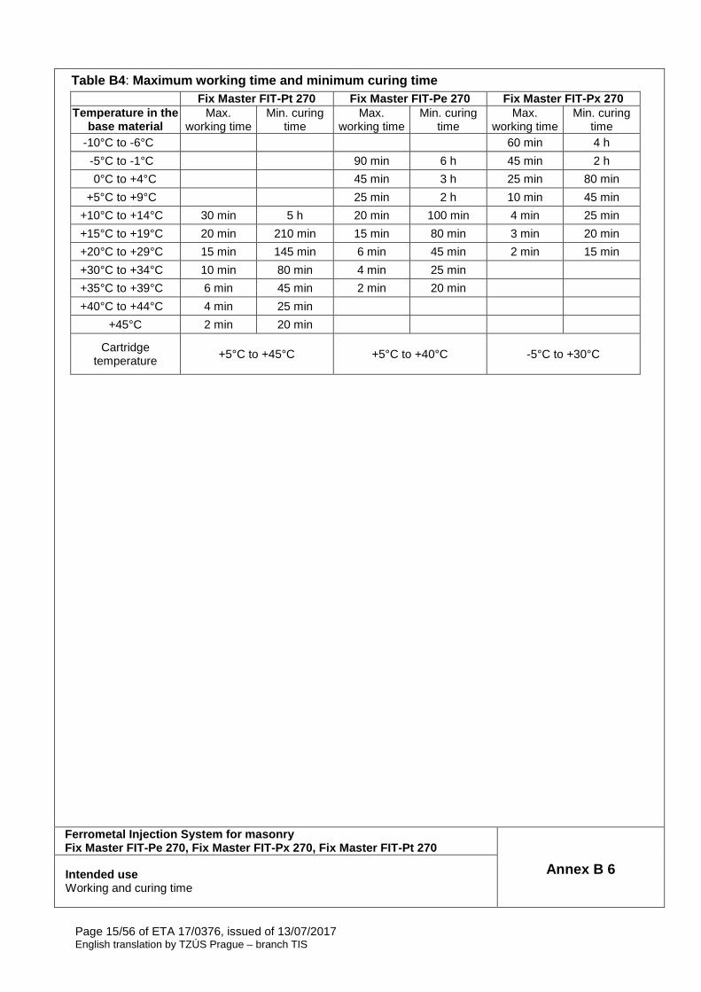
Table B4 : Maximum working time and minimum curing time Fix Master FIT -Pt 270 Fix Master FIT -Pe 270 Fix Master FIT -Px 270
Temperature in the base material
Max. working time
Min. curing time
Max. working time
Min. curing time
Max. working time
Min. curing time
-10°C to -6°C 60 min 4 h
-5°C to -1°C 90 min 6 h 45 min 2 h
0°C to +4°C 45 min 3 h 25 min 80 min
+5°C to +9°C 25 min 2 h 10 min 45 min
+10°C to +14°C 30 min 5 h 20 min 100 min 4 min 25 min
+15°C to +19°C 20 min 210 min 15 min 80 min 3 min 20 min
+20°C to +29°C 15 min 145 min 6 min 45 min 2 min 15 min
+30°C to +34°C 10 min 80 min 4 min 25 min
+35°C to +39°C 6 min 45 min 2 min 20 min
+40°C to +44°C 4 min 25 min
+45°C 2 min 20 min
Cartridge temperature
+5°C to +45°C +5°C to +40°C -5°C to +30°C
Ferrometal Injection System for masonry Fix Master FIT-Pe 270, Fix Master FIT-Px 270, Fix M aster FIT-Pt 270
Annex B 6 Intended use Working and curing time
Page 16/56 of ETA 17/0376, issued of 13/07/2017 English translation by TZÚS Prague – branch TIS
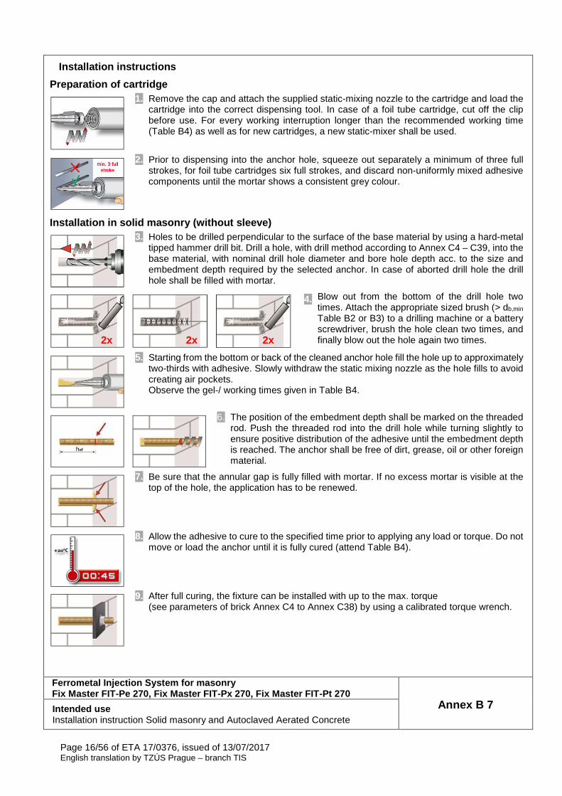
Installation instructions
Preparation of cartridge
1. Remove the cap and attach the supplied static-mixing nozzle to the cartridge and load the cartridge into the correct dispensing tool. In case of a foil tube cartridge, cut off the clip before use. For every working interruption longer than the recommended working time (Table B4) as well as for new cartridges, a new static-mixer shall be used.
2. Prior to dispensing into the anchor hole, squeeze out separately a minimum of three full strokes, for foil tube cartridges six full strokes, and discard non-uniformly mixed adhesive components until the mortar shows a consistent grey colour.
Installation in solid masonry (without sleeve)
3. Holes to be drilled perpendicular to the surface of the base material by using a hard-metal tipped hammer drill bit. Drill a hole, with drill method according to Annex C4 – C39, into the base material, with nominal drill hole diameter and bore hole depth acc. to the size and embedment depth required by the selected anchor. In case of aborted drill hole the drill hole shall be filled with mortar.
4. Blow out from the bottom of the drill hole two times. Attach the appropriate sized brush (> db,min Table B2 or B3) to a drilling machine or a battery screwdriver, brush the hole clean two times, and finally blow out the hole again two times.
5. Starting from the bottom or back of the cleaned anchor hole fill the hole up to approximately two-thirds with adhesive. Slowly withdraw the static mixing nozzle as the hole fills to avoid creating air pockets. Observe the gel-/ working times given in Table B4.
6. The position of the embedment depth shall be marked on the threaded rod. Push the threaded rod into the drill hole while turning slightly to ensure positive distribution of the adhesive until the embedment depth is reached. The anchor shall be free of dirt, grease, oil or other foreign material.
7. Be sure that the annular gap is fully filled with mortar. If no excess mortar is visible at the top of the hole, the application has to be renewed.
8. Allow the adhesive to cure to the specified time prior to applying any load or torque. Do not move or load the anchor until it is fully cured (attend Table B4).
9. After full curing, the fixture can be installed with up to the max. torque (see parameters of brick Annex C4 to Annex C38) by using a calibrated torque wrench.
Ferrometal Injection System for masonry Fix Master FIT-Pe 270, Fix Master FIT-Px 270, Fix M aster FIT-Pt 270
Annex B 7 Intended use Installation instruction Solid masonry and Autoclaved Aerated Concrete
2x 2x 2x
Page 17/56 of ETA 17/0376, issued of 13/07/2017 English translation by TZÚS Prague – branch TIS
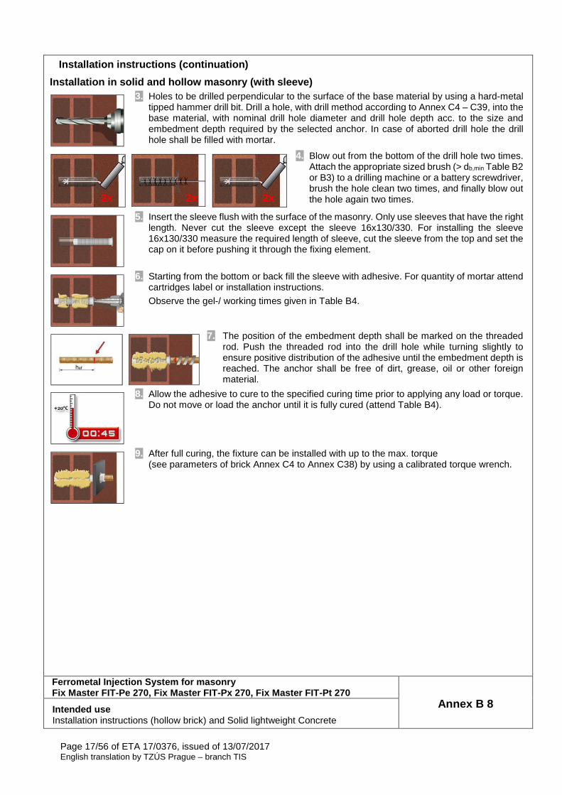
Installation instructions (continuation)
Installation in solid and hollow masonry (with slee ve)
3. Holes to be drilled perpendicular to the surface of the base material by using a hard-metal tipped hammer drill bit. Drill a hole, with drill method according to Annex C4 – C39, into the base material, with nominal drill hole diameter and drill hole depth acc. to the size and embedment depth required by the selected anchor. In case of aborted drill hole the drill hole shall be filled with mortar.
4. Blow out from the bottom of the drill hole two times. Attach the appropriate sized brush (> db,min Table B2 or B3) to a drilling machine or a battery screwdriver, brush the hole clean two times, and finally blow out the hole again two times.
5. Insert the sleeve flush with the surface of the masonry. Only use sleeves that have the right length. Never cut the sleeve except the sleeve 16x130/330. For installing the sleeve 16x130/330 measure the required length of sleeve, cut the sleeve from the top and set the cap on it before pushing it through the fixing element.
6. Starting from the bottom or back fill the sleeve with adhesive. For quantity of mortar attend cartridges label or installation instructions.
Observe the gel-/ working times given in Table B4.
7. The position of the embedment depth shall be marked on the threaded rod. Push the threaded rod into the drill hole while turning slightly to ensure positive distribution of the adhesive until the embedment depth is reached. The anchor shall be free of dirt, grease, oil or other foreign material.
8. Allow the adhesive to cure to the specified curing time prior to applying any load or torque. Do not move or load the anchor until it is fully cured (attend Table B4).
9. After full curing, the fixture can be installed with up to the max. torque (see parameters of brick Annex C4 to Annex C38) by using a calibrated torque wrench.
Ferrometal Injection System for masonry Fix Master FIT-Pe 270, Fix Master FIT-Px 270, Fix M aster FIT-Pt 270
Annex B 8 Intended use Installation instructions (hollow brick) and Solid lightweight Concrete
2x 2x 2x
Page 18/56 of ETA 17/0376, issued of 13/07/2017 English translation by TZÚS Prague – branch TIS
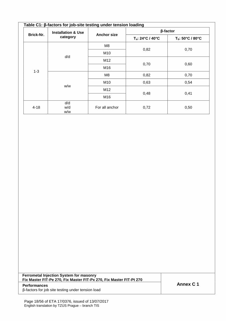
Table C1: β-factors for job -site testing under tension loading
Brick-Nr. Installation & Use category Anchor size
β-factor
Ta: 24°C / 40°C Tb: 50°C / 80°C
1-3
d/d
M8 0,82 0,70
M10
M12 0,70 0,60
M16
w/w
M8 0,82 0,70
M10 0,63 0,54
M12 0,48 0,41
M16
4-18 d/d w/d w/w
For all anchor 0,72 0,50
Ferrometal Injection System for masonry Fix Master FIT-Pe 270, Fix Master FIT-Px 270, Fix M aster FIT-Pt 270
Annex C 1 Performances β-factors for job site testing under tension load
Page 19/56 of ETA 17/0376, issued of 13/07/2017 English translation by TZÚS Prague – branch TIS
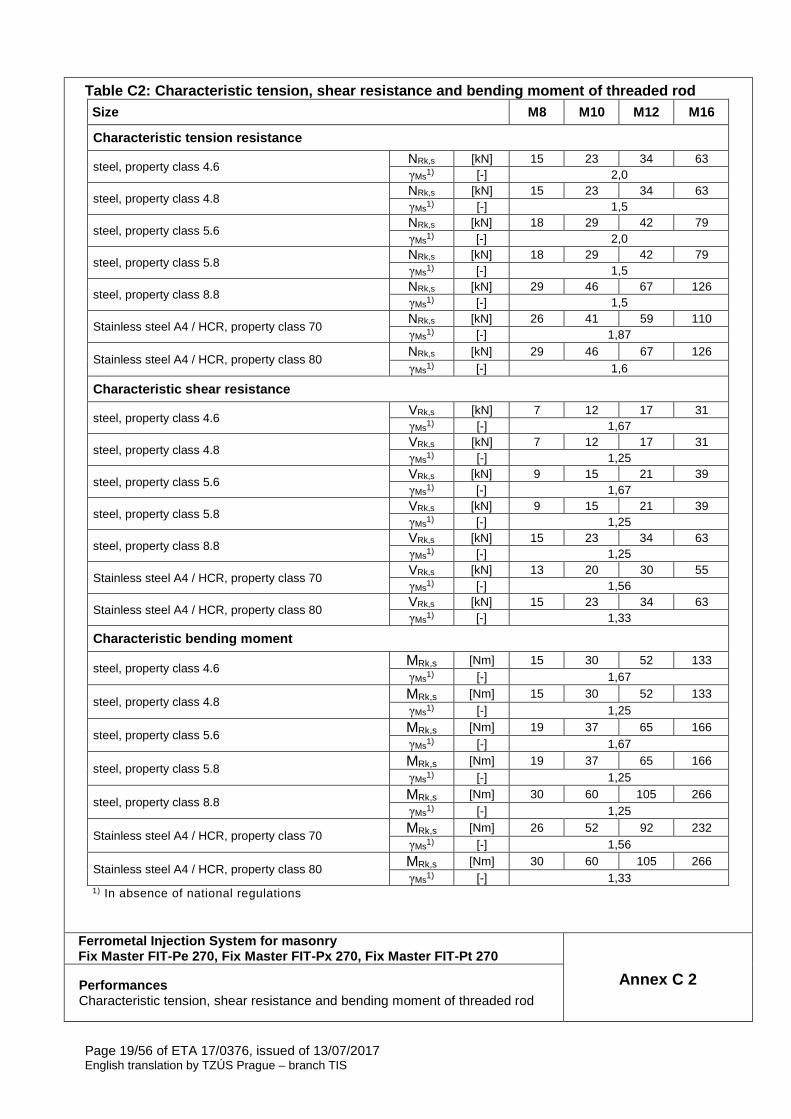
Table C2: Characteristic tension, shear resistance and bending moment of threaded rod Size M8 M10 M12 M16
Characteristic tension resistance
steel, property class 4.6 NRk,s [kN] 15 23 34 63 γMs1) [-] 2,0
steel, property class 4.8 NRk,s [kN] 15 23 34 63 γMs1) [-] 1,5
steel, property class 5.6 NRk,s [kN] 18 29 42 79 γMs1) [-] 2,0
steel, property class 5.8 NRk,s [kN] 18 29 42 79 γMs1) [-] 1,5
steel, property class 8.8 NRk,s [kN] 29 46 67 126 γMs1) [-] 1,5
Stainless steel A4 / HCR, property class 70 NRk,s [kN] 26 41 59 110 γMs1) [-] 1,87
Stainless steel A4 / HCR, property class 80 NRk,s [kN] 29 46 67 126 γMs1) [-] 1,6
Characteristic shear resistance
steel, property class 4.6 VRk,s [kN] 7 12 17 31 γMs1) [-] 1,67
steel, property class 4.8 VRk,s [kN] 7 12 17 31 γMs1) [-] 1,25
steel, property class 5.6 VRk,s [kN] 9 15 21 39 γMs1) [-] 1,67
steel, property class 5.8 VRk,s [kN] 9 15 21 39 γMs1) [-] 1,25
steel, property class 8.8 VRk,s [kN] 15 23 34 63 γMs1) [-] 1,25
Stainless steel A4 / HCR, property class 70 VRk,s [kN] 13 20 30 55 γMs1) [-] 1,56
Stainless steel A4 / HCR, property class 80 VRk,s [kN] 15 23 34 63 γMs1) [-] 1,33
Characteristic bending moment
steel, property class 4.6 MRk,s [Nm] 15 30 52 133 γMs1) [-] 1,67
steel, property class 4.8 MRk,s [Nm] 15 30 52 133 γMs1) [-] 1,25
steel, property class 5.6 MRk,s [Nm] 19 37 65 166 γMs1) [-] 1,67
steel, property class 5.8 MRk,s [Nm] 19 37 65 166 γMs1) [-] 1,25
steel, property class 8.8 MRk,s [Nm] 30 60 105 266 γMs1) [-] 1,25
Stainless steel A4 / HCR, property class 70 MRk,s [Nm] 26 52 92 232 γMs1) [-] 1,56
Stainless steel A4 / HCR, property class 80 MRk,s [Nm] 30 60 105 266 γMs1) [-] 1,33
1) In absence of national regulations
Ferrometal Injection System for masonry Fix Master FIT-Pe 270, Fix Master FIT-Px 270, Fix M aster FIT-Pt 270
Annex C 2 Performances Characteristic tension, shear resistance and bending moment of threaded rod
Page 20/56 of ETA 17/0376, issued of 13/07/2017 English translation by TZÚS Prague – branch TIS
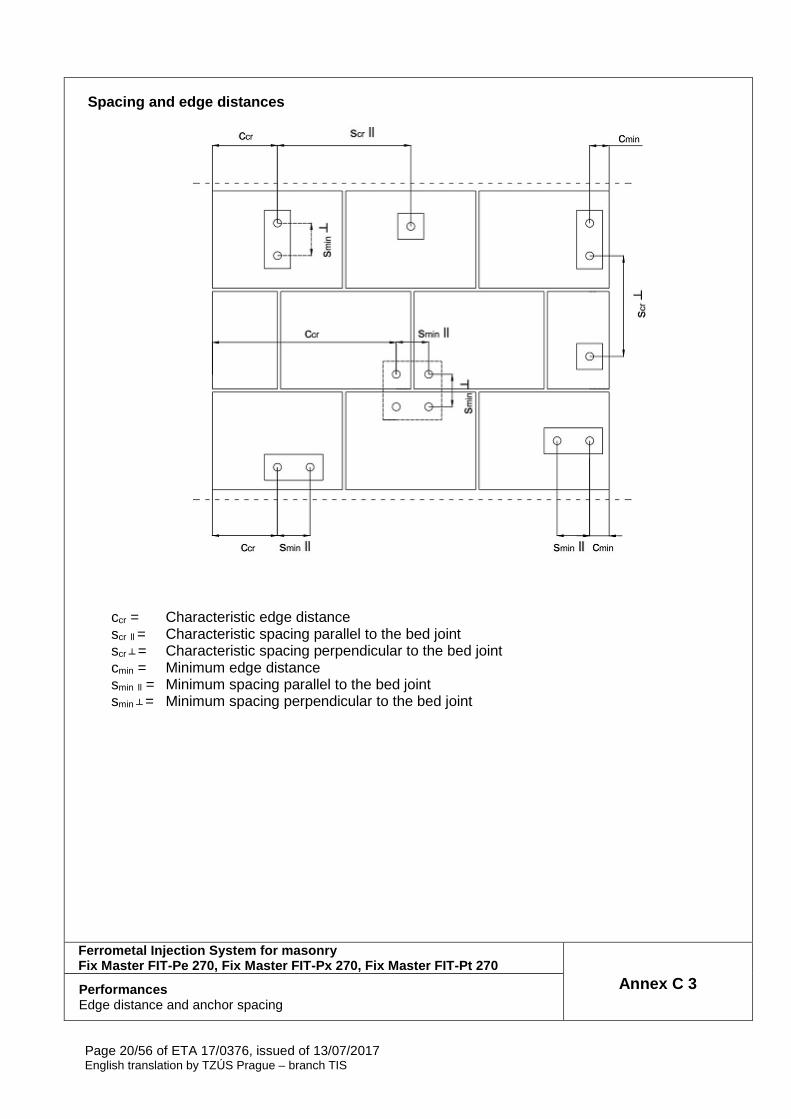
Spacing and edge distances
ccr = Characteristic edge distance scr ll = Characteristic spacing parallel to the bed joint scr ┴ = Characteristic spacing perpendicular to the bed joint cmin = Minimum edge distance smin ll = Minimum spacing parallel to the bed joint smin ┴ = Minimum spacing perpendicular to the bed joint
Ferrometal Injection System for masonry Fix Master FIT-Pe 270, Fix Master FIT-Px 270, Fix M aster FIT-Pt 270
Annex C 3 Performances Edge distance and anchor spacing
Page 21/56 of ETA 17/0376, issued of 13/07/2017 English translation by TZÚS Prague – branch TIS
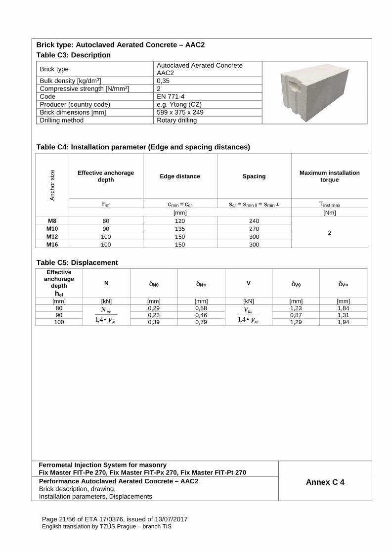
Brick type: Autoclaved Aerated Concrete – AAC2 Table C3: Description
Brick type Autoclaved Aerated Concrete AAC2
Bulk density [kg/dm3] 0,35 Compressive strength [N/mm2] 2 Code EN 771-4 Producer (country code) e.g. Ytong (CZ) Brick dimensions [mm] 599 x 375 x 249 Drilling method Rotary drilling
Table C4: Installation parameter (Edge and spacing distances)
Anc
hor
size
Effective anchorage depth Edge distance Spacing Maximum installation
torque
hef cmin = ccr scr = smin ll = smin ┴ Tinst,max [mm] [Nm]
M8 80 120 240
2 M10 90 135 270 M12 100 150 300 M16 100 150 300
Table C5: Displacement
Effective anchorage
depth hef
N δN0 δN∞ V δV0 δV∞
[mm] [kN] [mm] [mm] [kN] [mm] [mm] 80
M
RkN
γ•4,1
0,29 0,58
M
RkV
γ•4,1
1,23 1,84 90 0,23 0,46 0,87 1,31
100 0,39 0,79 1,29 1,94
Ferrometal Injection System for masonry Fix Master FIT-Pe 270, Fix Master FIT-Px 270, Fix M aster FIT-Pt 270
Annex C 4 Performance Autoclaved Aerated Concrete – AAC2 Brick description, drawing, Installation parameters, Displacements
Page 22/56 of ETA 17/0376, issued of 13/07/2017 English translation by TZÚS Prague – branch TIS
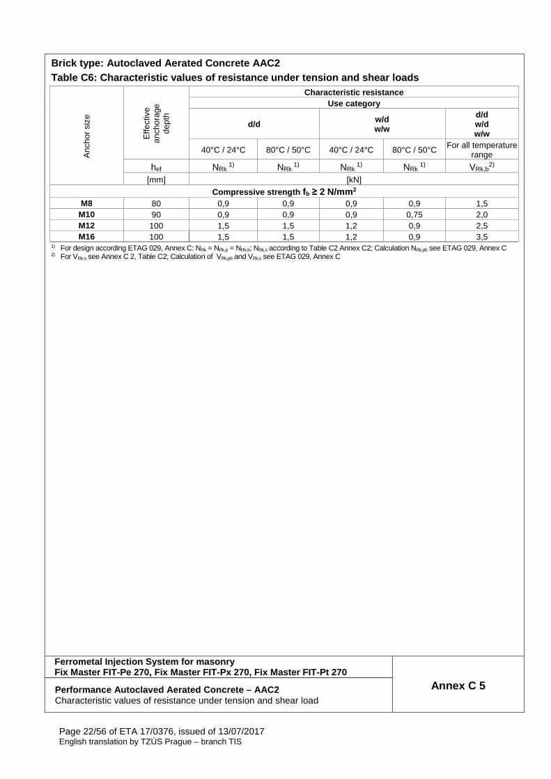
Brick type: Autoclaved Aerated Concrete AAC2 Table C6: Characteristic values of resistance under tension and shear loads
Anc
hor
size
Effe
ctiv
e an
chor
age
dept
h
Characteristic resistance Use category
d/d w/d w/w
d/d w/d w/w
40°C / 24°C 80°C / 50°C 40°C / 24°C 80°C / 50°C For all temperature range
hef NRk 1) NRk
1) NRk 1) NRk
1) VRk,b2)
[mm] [kN]
Compressive strength fb ≥ 2 N/mm 2 M8 80 0,9 0,9 0,9 0,9 1,5
M10 90 0,9 0,9 0,9 0,75 2,0 M12 100 1,5 1,5 1,2 0,9 2,5 M16 100 1,5 1,5 1,2 0,9 3,5
1) For design according ETAG 029, Annex C: NRk = NRk,p = NRk,b; NRk,s according to Table C2 Annex C2; Calculation NRk,pb see ETAG 029, Annex C 2) For VRk,s see Annex C 2, Table C2; Calculation of VRk,pb and VRk,c see ETAG 029, Annex C
Ferrometal Injection System for masonry Fix Master FIT-Pe 270, Fix Master FIT-Px 270, Fix M aster FIT-Pt 270
Annex C 5 Performance Autoclaved Aerated Concrete – AAC2 Characteristic values of resistance under tension and shear load

Page 23/56 of ETA 17/0376, issued of 13/07/2017 English translation by TZÚS Prague – branch TIS
Brick type: Autoclaved Aerated Concrete AAC4 Table C7: Description
Brick type Autoclaved Aerated Concrete AAC4
Bulk density [kg/dm3] 0,50 Compressive strength [N/mm2] 4 Code EN 771-4 Producer (country code) e.g. Ytong (CZ) Brick dimensions [mm] 499 x 375 x 249 Drilling method Rotary drilling
Table C8: Installation parameter (Edge and spacing distances)
Anc
hor
size
Effective anchorage depth Edge distance Spacing Maximum installation
torque
hef cmin = ccr scr = smin ll = smin ┴ Tinst,max [mm] [Nm]
M8 80 120 240
2 M10 90 135 270 M12 100 150 300 M16 100 150 300
Table C9: Displacement
Effective anchorage
depth hef
N δN0 δN∞ V δV0 δV∞
[mm] [kN] [mm] [mm] [kN] [mm] [mm] 80
M
RkN
γ•4,1
0,23 0,47
M
RkV
γ•4,1
1,23 1,84 90 0,58 1,17 0,87 1,31
100 0,10 0,21 1,29 1,94
Ferrometal Injection System for masonry Fix Master FIT-Pe 270, Fix Master FIT-Px 270, Fix M aster FIT-Pt 270
Annex C 6 Performance Autoclaved Aerated Concrete – AAC4 Brick description, drawing, Installation parameters, Displacement

Page 24/56 of ETA 17/0376, issued of 13/07/2017 English translation by TZÚS Prague – branch TIS
Brick type: Autoclaved Aerated Concrete AAC4 Table C10: Characteristic values of resistance unde r tension and shear loads
Anc
hor
size
Effe
ctiv
e an
chor
age
dept
h
Characteristic resistance Use category
d/d w/d w/w
d/d w/d w/w
40°C / 24°C 80°C / 50°C 40°C / 24°C 80°C / 50°C For all temperature range
hef NRk 1) NRk
1) NRk 1) NRk
1) VRk,b2)
[mm] [kN]
Compressive strength fb ≥ 4 N/mm 2 M8 80 0,9 0,9 0,9 0,9 1,5
M10 90 2,5 2,0 1,5 1,5 2,0 M12 100 2,5 2,0 2,0 1,5 2,5 M16 100 3,5 3,0 2,0 2,0 3,5
1) For design according ETAG 029, Annex C: NRk = NRk,p = NRk,b; NRk,s according to Table C2 Annex C2; Calculation NRk,pb see ETAG 029, Annex C 2) For VRk,s see Annex C 2, Table C2; Calculation of VRk,pb and VRk,c see ETAG 029, Annex C
Ferrometal Injection System for masonry Fix Master FIT-Pe 270, Fix Master FIT-Px 270, Fix M aster FIT-Pt 270
Annex C 7 Performance Autoclaved Aerated Concrete – AAC4 Characteristic values of resistance under tension and shear load
Page 25/56 of ETA 17/0376, issued of 13/07/2017 English translation by TZÚS Prague – branch TIS
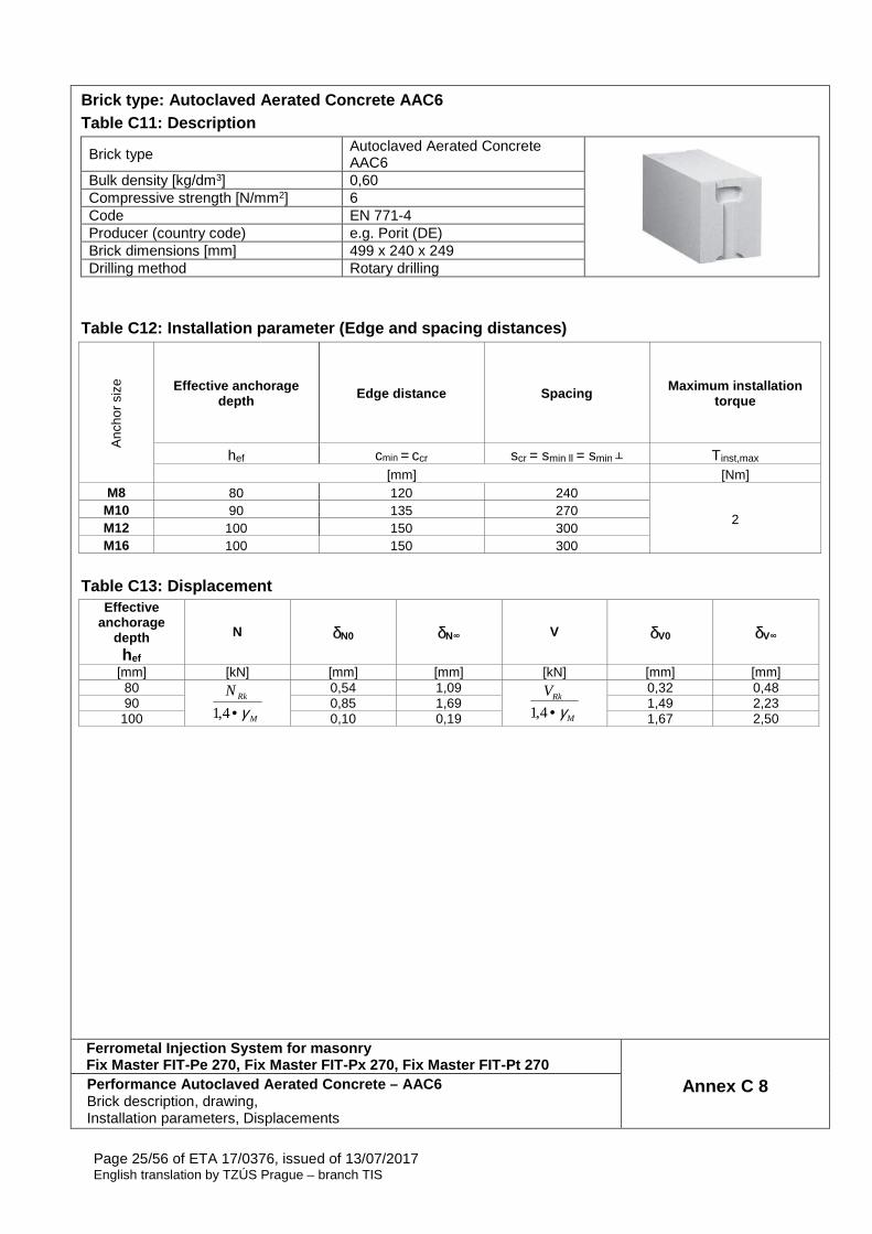
Brick type: Autoclaved Aerated Concrete AAC6 Table C11: Description
Brick type Autoclaved Aerated Concrete AAC6
Bulk density [kg/dm3] 0,60 Compressive strength [N/mm2] 6 Code EN 771-4 Producer (country code) e.g. Porit (DE) Brick dimensions [mm] 499 x 240 x 249 Drilling method Rotary drilling
Table C12: Installation parameter (Edge and spacing distances)
Anc
hor
size
Effective anchorage depth Edge distance Spacing Maximum installation
torque
hef cmin = ccr scr = smin ll = smin ┴ Tinst,max [mm] [Nm]
M8 80 120 240
2 M10 90 135 270 M12 100 150 300 M16 100 150 300
Table C13: Displacement
Effective anchorage
depth hef
N δN0 δN∞ V δV0 δV∞
[mm] [kN] [mm] [mm] [kN] [mm] [mm] 80
M
RkN
γ•4,1
0,54 1,09
M
RkV
γ•4,1
0,32 0,48 90 0,85 1,69 1,49 2,23
100 0,10 0,19 1,67 2,50
Ferrometal Injection System for masonry Fix Master FIT-Pe 270, Fix Master FIT-Px 270, Fix M aster FIT-Pt 270
Annex C 8 Performance Autoclaved Aerated Concrete – AAC6 Brick description, drawing, Installation parameters, Displacements

Page 26/56 of ETA 17/0376, issued of 13/07/2017 English translation by TZÚS Prague – branch TIS
Brick type: Autoclaved Aerated Concrete AAC6 Table C14: Characteristic values of resistance unde r tension and shear loads
Anc
hor
size
Effe
ctiv
e an
chor
age
dept
h
Characteristic resistance Use category
d/d w/d w/w
d/d w/d w/w
40°C / 24°C 80°C / 50°C 40°C / 24°C 80°C / 50°C For all temperature range
hef NRk 1) NRk
1) NRk 1) NRk
1) VRk,b2)
[mm] [kN]
Compressive strength fb ≥ 6 N/mm 2 M8 80 2,0 2,0 2,0 2,0 5,5
M10 90 3,0 2,5 2,5 2,0 9,0 M12 100 4,5 3,5 3,0 2,5 9,0 M16 100 5,5 4,5 3,5 3,0 11,0
1) For design according ETAG 029, Annex C: NRk = NRk,p = NRk,b; NRk,s according to Table C2 Annex C2; Calculation NRk,pb see ETAG 029, Annex C 2) For VRk,s see Annex C 2, Table C2; Calculation of VRk,pb and VRk,c see ETAG 029, Annex C
Ferrometal Injection System for masonry Fix Master FIT-Pe 270, Fix Master FIT-Px 270, Fix M aster FIT-Pt 270
Annex C 9 Performance Autoclaved Aerated Concrete – AAC6 Characteristic values of resistance under tension and shear load
Page 27/56 of ETA 17/0376, issued of 13/07/2017 English translation by TZÚS Prague – branch TIS
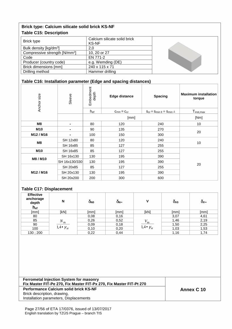
Brick type: Calcium silicate solid brick KS-NF Table C15: Description
Brick type Calcium silicate solid brick KS-NF
Bulk density [kg/dm3] 2,0 Compressive strength [N/mm2] 10, 20 or 27 Code EN 771-2 Producer (country code) e.g. Wemding (DE) Brick dimensions [mm] 240 x 115 x 71 Drilling method Hammer drilling
Table C16: Installation parameter (Edge and spacing distances)
Anc
hor
size
Sle
eve
Em
bedm
ent
dept
h Edge distance Spacing Maximum installation
torque
hef cmin = ccr scr = smin ll = smin ┴ Tinst,max [mm] [Nm]
M8 - 80 120 240 10
M10 - 90 135 270 20
M12 / M16 - 100 150 300
M8 SH 12x80 80 120 240
10 SH 16x85 85 127 255
M10 SH 16x85 85 127 255
20
M8 / M10 SH 16x130 130 195 390
SH 16x130/330 130 195 390
M12 / M16
SH 20x85 85 127 255
SH 20x130 130 195 390
SH 20x200 200 300 600
Table C17: Displacement
Effective anchorage
depth hef
N δN0 δN∞ V δV0 δV∞
[mm] [kN] [mm] [mm] [kN] [mm] [mm] 80
M
RkN
γ•4,1
0,08 0,16
M
RkV
γ•4,1
3,07 4,61 85 0,26 0,52 1,46 2,19 90 0,09 0,18 1,50 2,25
100 0,10 0,20 1,03 1,53 130 ; 200 0,22 0,44 1,16 1,74
Ferrometal Injection System for masonry Fix Master FIT-Pe 270, Fix Master FIT-Px 270, Fix M aster FIT-Pt 270
Annex C 10 Performance Calcium solid brick KS-NF Brick description, drawing, Installation parameters, Displacements

Page 28/56 of ETA 17/0376, issued of 13/07/2017 English translation by TZÚS Prague – branch TIS
Brick type: Calcium silicate solid brick KS-NF Table C18: Characteristic values of resistance unde r tension and shear loads
Anc
hor
size
Sle
eve
Effe
ctiv
e an
chor
age
dept
h
Characteristic resistance Use category d/d; w/d; w/w
40°C / 24°C 80°C / 50°C For all temperature range
hef NRk 1) NRk
1) VRk,b2)
[mm] [kN]
Compressive strength fb ≥ 10 N/mm 2 M8 - 80 3,0 2,0 3,0
M10 - 90 3,0 2,0 3,0 M12 - 100 4,0 2,5 3,5 M16 - 100 3,0 2,0 3,5
M8 SH 12x80 80 2,5 2,0 2,5 SH 16x85 85 2,5 2,0 3,0
SH16x130 / SH16x130/330 130 4,0 2,5 4,0
M10 SH 16x85 85 2,5 2,0 3,0
SH16x130/330 130 4,5 3,0 4,0
M12 / M16 SH 20x85 85 2,5 2,0 3,0
SH 20x130 / SH 20x200 130 / 200 4,5 2,5 4,0 Compressive strength f b ≥ 20 N/mm 2
M8 - 80 4,5 3,0 4,5 M10 - 90 4,5 3,0 4,5 M12 - 100 5,5 3,5 5,0 M16 - 100 4,5 3,0 5,0
M8 SH 12x80 80 4,0 2,5 4,0 SH 16x85 85 4,0 2,5 4,5
SH16x130 / SH16x130/330 130 6,0 3,5 5,5
M10 SH 16x85 85 4,0 2,5 4,5
SH 16x130/330 130 6,0 4,0 5,5
M12 / M16 SH 20x85 85 4,0 2,5 5,0
SH 20x130 / SH 20x200 130 / 200 6,0 4,0 5,5 Compressive strength f b ≥ 27 N/mm 2
M8 - 80 5,5 3,5 5,0 M10 - 90 5,5 3,5 5,5 M12 - 100 6,5 4,5 6,0 M16 - 100 5,5 3,5 6,0
M8 SH 12x80 80 4,5 3,0 4,5 SH 16x85 85 4,5 3,0 5,5
SH16x130 / SH16x130/330 130 6,5 4,5 6,5
M10 SH 16x85 85 4,5 3,0 5,5
SH 16x130/330 130 6,5 4,5 6,5
M12 / M16 SH 20x85 85 4,5 3,0 5,5
SH 20x130 / SH 20x200 130 / 200 6,5 4,5 6,5 1) For design according ETAG 029, Annex C: NRk = NRk,p = NRk,b; NRk,s according to Table C2 Annex C2; Calculation NRk,pb see ETAG 029, Annex C 2) For VRk,s see Annex C 2, Table C2; Calculation of VRk,pb and VRk,c see ETAG 029, Annex C
Ferrometal Injection System for masonry Fix Master FIT-Pe 270, Fix Master FIT-Px 270, Fix M aster FIT-Pt 270
Annex C 11 Performance Calcium solid brick KS-NF Characteristic values of resistance under tension and shear load
Page 29/56 of ETA 17/0376, issued of 13/07/2017 English translation by TZÚS Prague – branch TIS
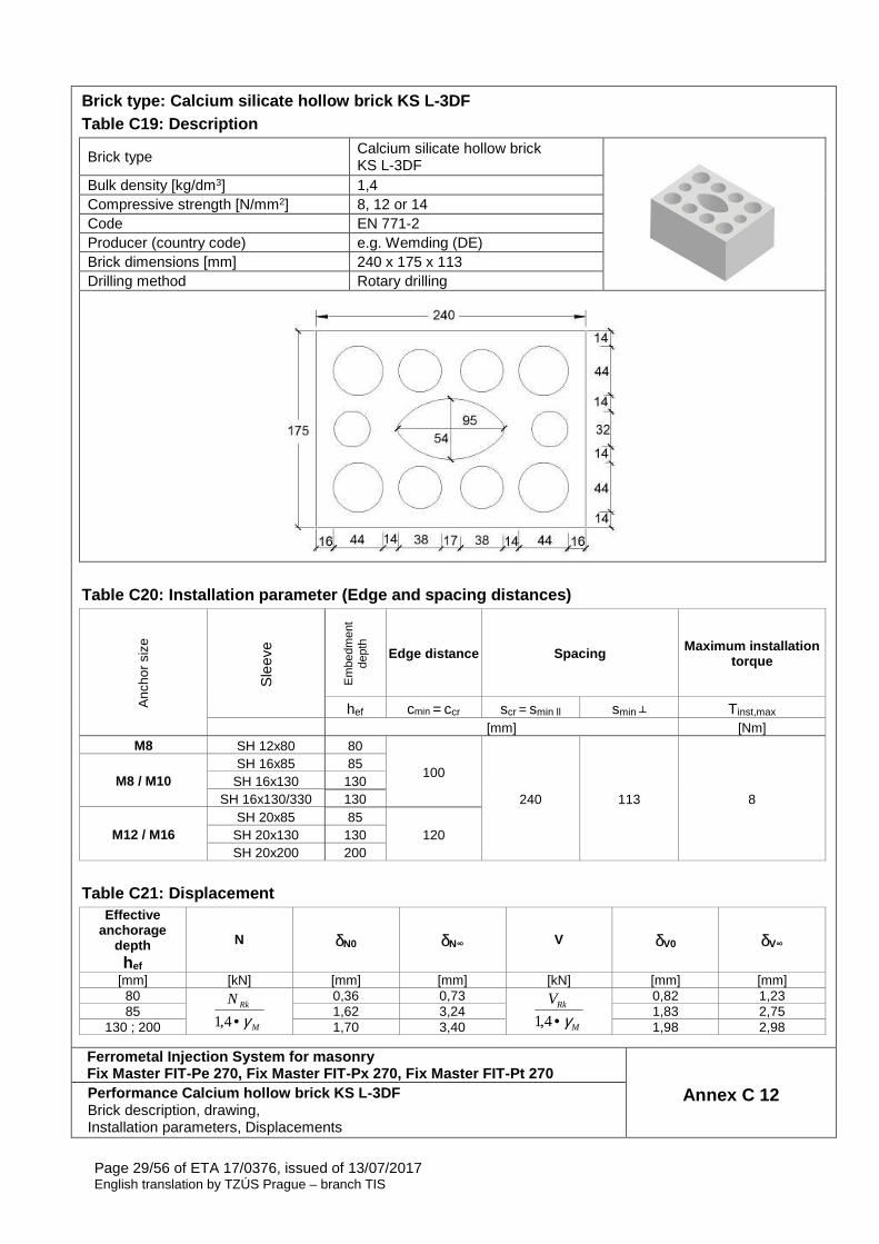
Brick type: Calcium silicate hollow brick KS L-3DF Table C19: Description
Brick type Calcium silicate hollow brick KS L-3DF
Bulk density [kg/dm3] 1,4 Compressive strength [N/mm2] 8, 12 or 14 Code EN 771-2 Producer (country code) e.g. Wemding (DE) Brick dimensions [mm] 240 x 175 x 113 Drilling method Rotary drilling
Table C20: Installation parameter (Edge and spacing distances)
Anc
hor
size
Sle
eve
Em
bedm
ent
dept
h
Edge distance Spacing Maximum installation torque
hef cmin = ccr scr = smin ll smin ┴ Tinst,max [mm] [Nm]
M8 SH 12x80 80
100
240 113 8 M8 / M10
SH 16x85 85 SH 16x130 130
SH 16x130/330 130
M12 / M16 SH 20x85 85
120 SH 20x130 130 SH 20x200 200
Table C21: Displacement
Effective anchorage
depth hef
N δN0 δN∞ V δV0 δV∞
[mm] [kN] [mm] [mm] [kN] [mm] [mm] 80
M
RkN
γ•4,1
0,36 0,73
M
RkV
γ•4,1
0,82 1,23 85 1,62 3,24 1,83 2,75
130 ; 200 1,70 3,40 1,98 2,98
Ferrometal Injection System for masonry Fix Master FIT-Pe 270, Fix Master FIT-Px 270, Fix M aster FIT-Pt 270
Annex C 12 Performance Calcium hollow brick KS L-3DF Brick description, drawing, Installation parameters, Displacements
Page 30/56 of ETA 17/0376, issued of 13/07/2017 English translation by TZÚS Prague – branch TIS
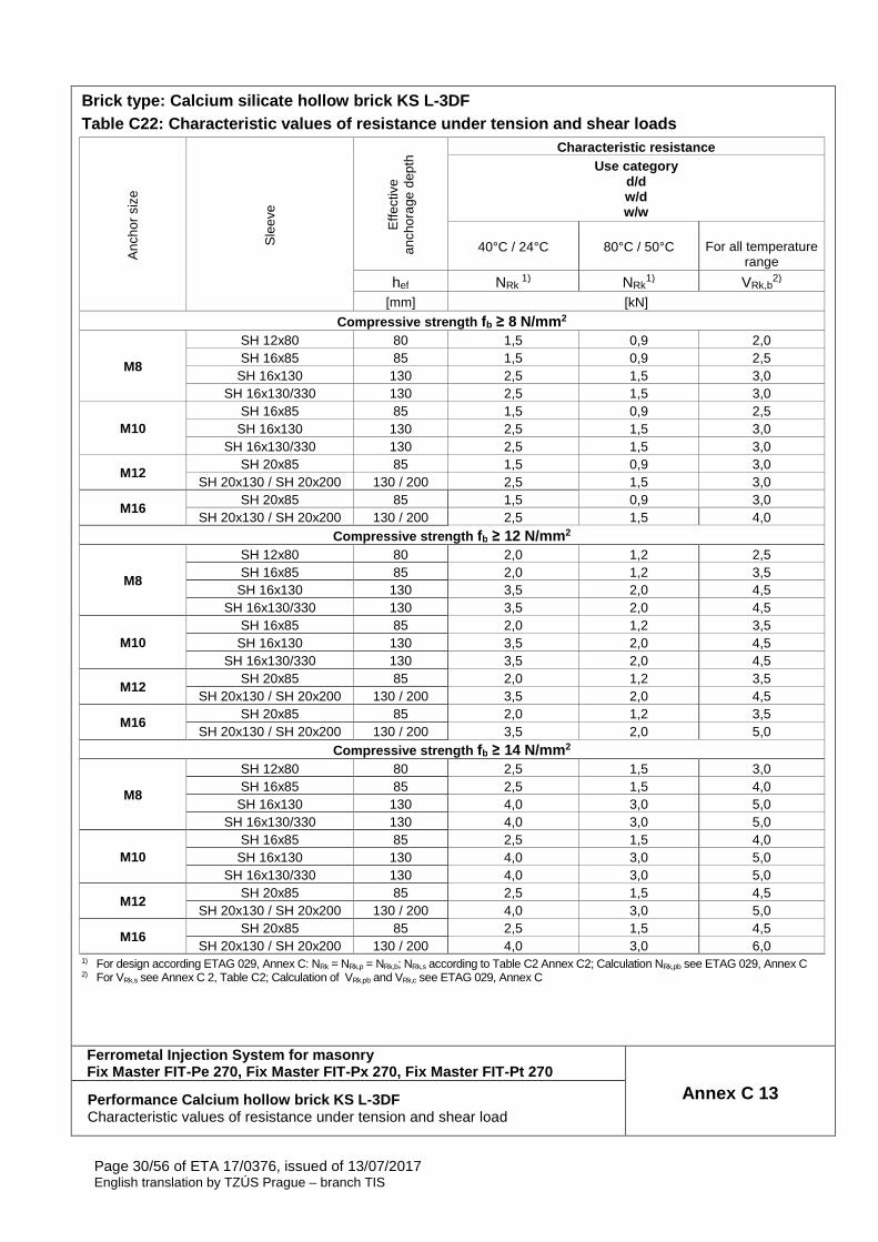
Brick type: Calcium silicate hollow brick KS L-3DF Table C22: Characteristic values of resistance unde r tension and shear loads
Anc
hor
size
Sle
eve
Effe
ctiv
e an
chor
age
dept
h Characteristic resistance
Use category d/d w/d w/w
40°C / 24°C 80°C / 50°C
For all temperature range
hef NRk 1) NRk
1) VRk,b2)
[mm] [kN]
Compressive strength fb ≥ 8 N/mm 2
M8
SH 12x80 80 1,5 0,9 2,0 SH 16x85 85 1,5 0,9 2,5
SH 16x130 130 2,5 1,5 3,0 SH 16x130/330 130 2,5 1,5 3,0
M10 SH 16x85 85 1,5 0,9 2,5
SH 16x130 130 2,5 1,5 3,0 SH 16x130/330 130 2,5 1,5 3,0
M12 SH 20x85 85 1,5 0,9 3,0
SH 20x130 / SH 20x200 130 / 200 2,5 1,5 3,0
M16 SH 20x85 85 1,5 0,9 3,0
SH 20x130 / SH 20x200 130 / 200 2,5 1,5 4,0 Compressive strength fb ≥ 12 N/mm 2
M8
SH 12x80 80 2,0 1,2 2,5 SH 16x85 85 2,0 1,2 3,5
SH 16x130 130 3,5 2,0 4,5 SH 16x130/330 130 3,5 2,0 4,5
M10 SH 16x85 85 2,0 1,2 3,5
SH 16x130 130 3,5 2,0 4,5 SH 16x130/330 130 3,5 2,0 4,5
M12 SH 20x85 85 2,0 1,2 3,5
SH 20x130 / SH 20x200 130 / 200 3,5 2,0 4,5
M16 SH 20x85 85 2,0 1,2 3,5
SH 20x130 / SH 20x200 130 / 200 3,5 2,0 5,0 Compressive strength fb ≥ 14 N/mm 2
M8
SH 12x80 80 2,5 1,5 3,0 SH 16x85 85 2,5 1,5 4,0
SH 16x130 130 4,0 3,0 5,0 SH 16x130/330 130 4,0 3,0 5,0
M10 SH 16x85 85 2,5 1,5 4,0
SH 16x130 130 4,0 3,0 5,0 SH 16x130/330 130 4,0 3,0 5,0
M12 SH 20x85 85 2,5 1,5 4,5
SH 20x130 / SH 20x200 130 / 200 4,0 3,0 5,0
M16 SH 20x85 85 2,5 1,5 4,5
SH 20x130 / SH 20x200 130 / 200 4,0 3,0 6,0 1) For design according ETAG 029, Annex C: NRk = NRk,p = NRk,b; NRk,s according to Table C2 Annex C2; Calculation NRk,pb see ETAG 029, Annex C 2) For VRk,s see Annex C 2, Table C2; Calculation of VRk,pb and VRk,c see ETAG 029, Annex C
Ferrometal Injection System for masonry Fix Master FIT-Pe 270, Fix Master FIT-Px 270, Fix M aster FIT-Pt 270
Annex C 13 Performance Calcium hollow brick KS L-3DF Characteristic values of resistance under tension and shear load
Page 31/56 of ETA 17/0376, issued of 13/07/2017 English translation by TZÚS Prague – branch TIS
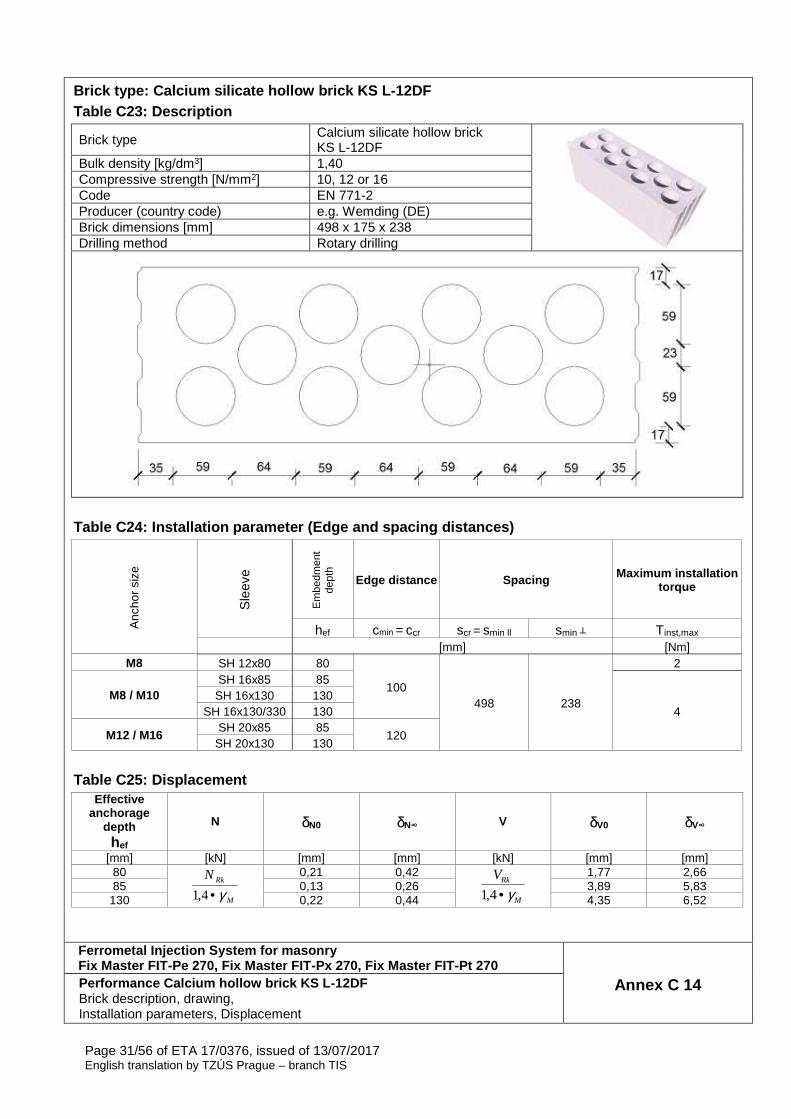
Brick type: Calcium silicate hollow brick KS L-12DF Table C23: Description
Brick type Calcium silicate hollow brick KS L-12DF
Bulk density [kg/dm3] 1,40 Compressive strength [N/mm2] 10, 12 or 16 Code EN 771-2 Producer (country code) e.g. Wemding (DE) Brick dimensions [mm] 498 x 175 x 238 Drilling method Rotary drilling
Table C24: Installation parameter (Edge and spacing distances)
Anc
hor
size
Sle
eve
Em
bedm
ent
dept
h
Edge distance Spacing Maximum installation torque
hef cmin = ccr scr = smin ll smin ┴ Tinst,max [mm] [Nm]
M8 SH 12x80 80
100 498 238
2
M8 / M10 SH 16x85 85
4 SH 16x130 130
SH 16x130/330 130
M12 / M16 SH 20x85 85
120 SH 20x130 130
Table C25: Displacement
Effective anchorage
depth hef
N δN0 δN∞ V δV0 δV∞
[mm] [kN] [mm] [mm] [kN] [mm] [mm] 80
M
RkN
γ•4,1
0,21 0,42
M
RkV
γ•4,1
1,77 2,66 85 0,13 0,26 3,89 5,83
130 0,22 0,44 4,35 6,52
Ferrometal Injection System for masonry Fix Master FIT-Pe 270, Fix Master FIT-Px 270, Fix M aster FIT-Pt 270
Annex C 14 Performance Calcium hollow brick KS L-12DF Brick description, drawing, Installation parameters, Displacement

Page 32/56 of ETA 17/0376, issued of 13/07/2017 English translation by TZÚS Prague – branch TIS
Brick type: Calcium silicate hollow brick KS L-12DF Table C26: Characteristic values of resistance unde r tension and shear loads
Anc
hor
size
Sle
eve
Effe
ctiv
e an
chor
age
dept
h Characteristic resistance
Use category d/d w/d w/w
40°C / 24°C 80°C / 50°C For all temperature range
hef NRk 1) NRk
1) VRk,b2)
[mm] [kN]
Compressive strength fb ≥ 10 N/mm 2
M8
SH 12x80 80 0,4 0,3 3,0 SH 16x85 85 1,2 0,9 6,0
SH 16x130 130 3,5 2,5 7,0 SH 16x130/330 130 3,5 2,5 7,0
M10 SH 16x85 85 1,2 0,9 6,0
SH 16x130 130 3,5 2,5 7,0 SH 16x130/330 130 3,5 2,5 7,0
M12 / M16 SH 20x85 85 1,2 0,9 6,0
SH 20x130 / SH 20x200 130 / 200 3,5 2,5 7,0 Compressive strength fb ≥ 12 N/mm 2
M8
SH 12x80 80 0,4 0,3 3,5 SH 16x85 85 1,5 0,9 7,0
SH 16x130 130 4,5 3,0 8,0 SH 16x130/330 130 4,5 3,0 8,0
M10 SH 16x85 85 1,5 0,9 7,0
SH 16x130 130 4,5 3,0 8,0 SH 16x130/330 130 4,5 3,0 8,0
M12 / M16 SH 20x85 85 1,5 0,9 7,0
SH 20x130 / SH 20x200 130 / 200 4,5 3,0 8,0 Compressive strength fb ≥ 16 N/mm 2
M8
SH 12x80 80 0,5 0,4 4,0 SH 16x85 85 2,0 1,2 9,0
SH 16x130 130 5,5 3,5 10,0 SH 16x130/330 130 5,5 3,5 10,0
M10 SH 16x85 85 2,0 1,2 9,0
SH 16x130 130 5,5 3,5 10,0 SH 16x130/330 130 5,5 3,5 10,0
M12 / M16 SH 20x85 85 2,0 1,2 8,5
SH 20x130 / SH 20x200 130 / 200 5,5 3,5 10,0 1) For design according ETAG 029, Annex C: NRk = NRk,p = NRk,b; NRk,s according to Table C2 Annex C2; Calculation NRk,pb see ETAG 029, Annex C 2) For VRk,s see Annex C 2, Table C2; Calculation of VRk,pb and VRk,c see ETAG 029, Annex C
Ferrometal Injection System for masonry Fix Master FIT-Pe 270, Fix Master FIT-Px 270, Fix M aster FIT-Pt 270
Annex C 15 Performance Calcium hollow brick KS L-12DF Characteristic values of resistance under tension and shear load
Page 33/56 of ETA 17/0376, issued of 13/07/2017 English translation by TZÚS Prague – branch TIS
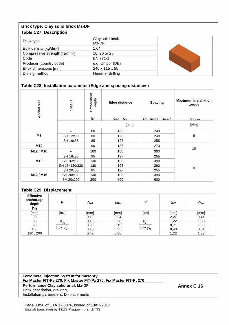
Brick type: Clay solid brick Mz-DF Table C27: Description
Brick type Clay solid brick Mz-DF
Bulk density [kg/dm3] 1,64 Compressive strength [N/mm2] 10, 20 or 28 Code EN 771-1 Producer (country code) e.g. Unipor (DE) Brick dimensions [mm] 240 x 115 x 55 Drilling method Hammer drilling
Table C28: Installation parameter (Edge and spacing distances)
Anc
hor
size
Sle
eve
Em
bedm
ent
dept
h
Edge distance Spacing Maximum installation torque
hef cmin = ccr scr = smin ll = smin ┴ Tinst,max [mm] [Nm]
M8 - 80 120 240
6 SH 12x80 80 120 240 SH 16x85 85 127 255
M10 - 90 135 270 10
M12 / M16 - 100 150 300
M10 SH 16x85 85 127 255
8
SH 16x130 130 195 390 SH 16x130/330 130 195 390
M12 / M16 SH 20x85 85 127 255
SH 20x130 130 195 390 SH 20x200 200 300 600
Table C29: Displacement
Effective anchorage
depth hef
N δN0 δN∞ V δV0 δV∞
[mm] [kN] [mm] [mm] [kN] [mm] [mm] 80
M
RkN
γ•4,1
0,12 0,24
M
RkV
γ•4,1
2,27 3,41 85 0,13 0,26 1,22 1,83 90 0,06 0,13 0,71 1,06
100 0,18 0,35 0,43 0,64 130 ; 200 0,42 0,85 1,22 1,83
Ferrometal Injection System for masonry Fix Master FIT-Pe 270, Fix Master FIT-Px 270, Fix M aster FIT-Pt 270
Annex C 16 Performance Clay solid brick Mz-DF Brick description, drawing, Installation parameters, Displacements
Page 34/56 of ETA 17/0376, issued of 13/07/2017 English translation by TZÚS Prague – branch TIS
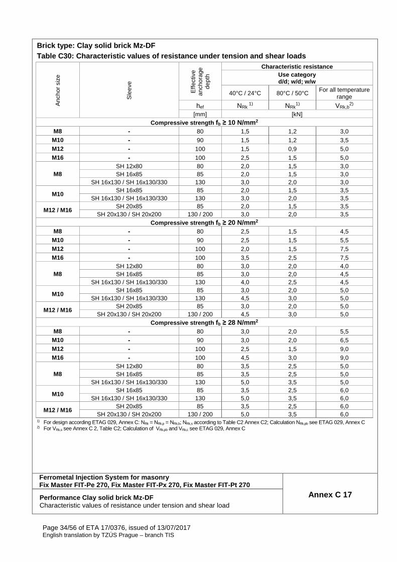
Brick type: Clay solid brick Mz-DF Table C30: Characteristic values of resistance unde r tension and shear loads
Anc
hor
size
Sle
eve
Effe
ctiv
e an
chor
age
dept
h
Characteristic resistance Use category d/d; w/d; w/w
40°C / 24°C 80°C / 50°C For all temperature range
hef NRk 1) NRk
1) VRk,b2)
[mm] [kN] Compressive strength fb ≥ 10 N/mm 2
M8 - 80 1,5 1,2 3,0 M10 - 90 1,5 1,2 3,5 M12 - 100 1,5 0,9 5,0 M16 - 100 2,5 1,5 5,0
M8 SH 12x80 80 2,0 1,5 3,0 SH 16x85 85 2,0 1,5 3,0
SH 16x130 / SH 16x130/330 130 3,0 2,0 3,0
M10 SH 16x85 85 2,0 1,5 3,5
SH 16x130 / SH 16x130/330 130 3,0 2,0 3,5
M12 / M16 SH 20x85 85 2,0 1,5 3,5
SH 20x130 / SH 20x200 130 / 200 3,0 2,0 3,5 Compressive strength fb ≥ 20 N/mm 2
M8 - 80 2,5 1,5 4,5 M10 - 90 2,5 1,5 5,5 M12 - 100 2,0 1,5 7,5 M16 - 100 3,5 2,5 7,5
M8 SH 12x80 80 3,0 2,0 4,0 SH 16x85 85 3,0 2,0 4,5
SH 16x130 / SH 16x130/330 130 4,0 2,5 4,5
M10 SH 16x85 85 3,0 2,0 5,0
SH 16x130 / SH 16x130/330 130 4,5 3,0 5,0
M12 / M16 SH 20x85 85 3,0 2,0 5,0
SH 20x130 / SH 20x200 130 / 200 4,5 3,0 5,0 Compressive strength fb ≥ 28 N/mm 2
M8 - 80 3,0 2,0 5,5 M10 - 90 3,0 2,0 6,5 M12 - 100 2,5 1,5 9,0 M16 - 100 4,5 3,0 9,0
M8 SH 12x80 80 3,5 2,5 5,0 SH 16x85 85 3,5 2,5 5,0
SH 16x130 / SH 16x130/330 130 5,0 3,5 5,0
M10 SH 16x85 85 3,5 2,5 6,0
SH 16x130 / SH 16x130/330 130 5,0 3,5 6,0
M12 / M16 SH 20x85 85 3,5 2,5 6,0
SH 20x130 / SH 20x200 130 / 200 5,0 3,5 6,0 1) For design according ETAG 029, Annex C: NRk = NRk,p = NRk,b; NRk,s according to Table C2 Annex C2; Calculation NRk,pb see ETAG 029, Annex C 2) For VRk,s see Annex C 2, Table C2; Calculation of VRk,pb and VRk,c see ETAG 029, Annex C
Ferrometal Injection System for masonry Fix Master FIT-Pe 270, Fix Master FIT-Px 270, Fix M aster FIT-Pt 270
Annex C 17 Performance Clay solid brick Mz-DF Characteristic values of resistance under tension and shear load
Page 35/56 of ETA 17/0376, issued of 13/07/2017 English translation by TZÚS Prague – branch TIS
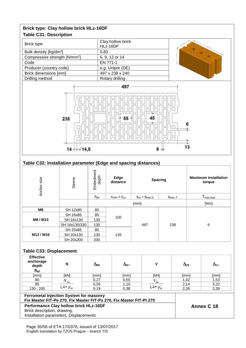
Brick type: Clay hollow brick HLz-16DF Table C31: Description
Brick type Clay hollow brick HLz-16DF
Bulk density [kg/dm3] 0,83 Compressive strength [N/mm2] 6, 9, 12 or 14 Code EN 771-1 Producer (country code) e.g. Unipor (DE) Brick dimensions [mm] 497 x 238 x 240 Drilling method Rotary drilling
Table C32: Installation parameter (Edge and spacing distances)
Anc
hor
size
Sle
eve
Em
bedm
ent
dept
h Edge distance Spacing Maximum installation
torque
hef cmin = ccr scr = smin ll smin ┴ Tinst,max [mm] [Nm]
M8 SH 12x80 80
100
497 238 6 M8 / M10
SH 16x85 85 SH 16x130 130
SH 16x130/330 130
M12 / M16 SH 20x85 85
120 SH 20x130 130 SH 20x200 200
Table C33: Displacement
Effective anchorage
depth hef
N δN0 δN∞ V δV0 δV∞
[mm] [kN] [mm] [mm] [kN] [mm] [mm] 80
M
RkN
γ•4,1
0,27 0,55
M
RkV
γ•4,1
1,02 1,53 85 0,55 1,10 2,14 3,22
130 ; 200 0,19 0,38 2,26 3,39
Ferrometal Injection System for masonry Fix Master FIT-Pe 270, Fix Master FIT-Px 270, Fix M aster FIT-Pt 270
Annex C 18 Performance Clay hollow brick HLz-16DF Brick description, drawing, Installation parameters, Displacements
Page 36/56 of ETA 17/0376, issued of 13/07/2017 English translation by TZÚS Prague – branch TIS
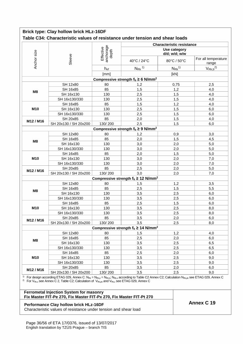
Brick type: Clay hollow brick HLz-16DF Table C34: Characteristic values of resistance unde r tension and shear loads
Anc
hor
size
Sle
eve
Effe
ctiv
e an
chor
age
dept
h
Characteristic resistance Use category d/d; w/d; w/w
40°C / 24°C 80°C / 50°C For all temperature range
hef NRk 1) NRk
1) VRk,b2)
[mm] [kN]
Compressive strength fb ≥ 6 N/mm 2
M8
SH 12x80 80 1,2 0,75 2,5 SH 16x85 85 1,5 1,2 4,0
SH 16x130 130 2,5 1,5 4,0 SH 16x130/330 130 2,5 1,5 4,0
M10 SH 16x85 85 1,5 1,2 4,0
SH 16x130 130 2,5 1,5 6,0 SH 16x130/330 130 2,5 1,5 6,0
M12 / M16 SH 20x85 85 2,0 1,5 4,0
SH 20x130 / SH 20x200 130/ 200 2,5 1,5 6,0 Compressive strength fb ≥ 9 N/mm 2
M8
SH 12x80 80 1,2 0,9 3,0 SH 16x85 85 2,0 1,5 4,5
SH 16x130 130 3,0 2,0 5,0 SH 16x130/330 130 3,0 2,0 5,0
M10 SH 16x85 85 2,0 1,5 5,0
SH 16x130 130 3,0 2,0 7,0 SH 16x130/330 130 3,0 2,0 7,0
M12 / M16 SH 20x85 85 2,5 2,0 5,0
SH 20x130 / SH 20x200 130/ 200 3,0 2,0 7,0 Compressive strength fb ≥ 12 N/mm 2
M8
SH 12x80 80 1,5 1,2 3,5 SH 16x85 85 2,5 1,5 5,5
SH 16x130 130 3,5 2,5 6,0 SH 16x130/330 130 3,5 2,5 6,0
M10 SH 16x85 85 2,5 1,5 6,0
SH 16x130 130 3,5 2,5 8,0 SH 16x130/330 130 3,5 2,5 8,0
M12 / M16 SH 20x85 85 3,5 2,0 6,0
SH 20x130 / SH 20x200 130/ 200 3,5 2,5 8,0 Compressive strength fb ≥ 14 N/mm 2
M8
SH 12x80 80 1,5 1,2 4,0 SH 16x85 85 2,5 2,0 6,0
SH 16x130 130 3,5 2,5 6,5 SH 16x130/330 130 3,5 2,5 6,5
M10 SH 16x85 85 2,5 2,0 6,0
SH 16x130 130 3,5 2,5 9,0 SH 16x130/330 130 3,5 2,5 9,0
M12 / M16 SH 20x85 85 3,5 2,0 6,0
SH 20x130 / SH 20x200 130/ 200 3,5 2,5 9,0 1) For design according ETAG 029, Annex C: NRk = NRk,p = NRk,b; NRk,s according to Table C2 Annex C2; Calculation NRk,pb see ETAG 029, Annex C 2) For VRk,s see Annex C 2, Table C2; Calculation of VRk,pb and VRk,c see ETAG 029, Annex C
Ferrometal Injection System for masonry Fix Master FIT-Pe 270, Fix Master FIT-Px 270, Fix M aster FIT-Pt 270
Annex C 19 Performance Clay hollow brick HLz-16DF Characteristic values of resistance under tension and shear load
Page 37/56 of ETA 17/0376, issued of 13/07/2017 English translation by TZÚS Prague – branch TIS
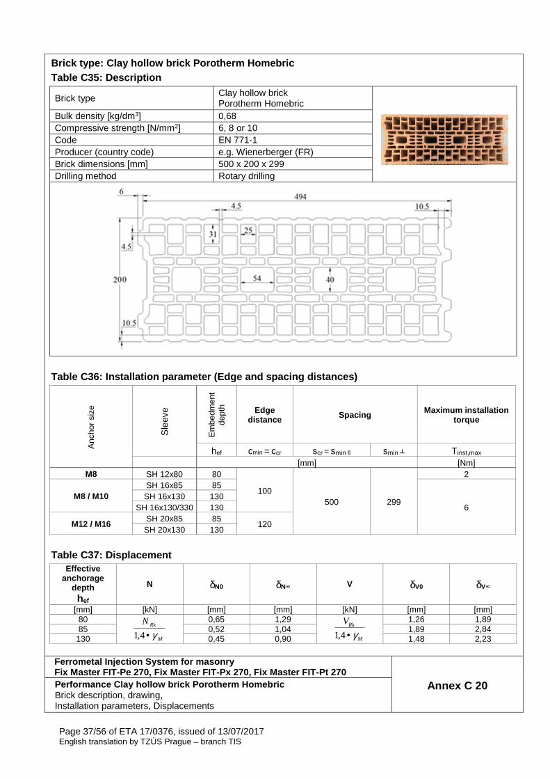
Brick type: Clay hollow brick Porotherm Homebric Table C35: Description
Brick type Clay hollow brick Porotherm Homebric
Bulk density [kg/dm3] 0,68 Compressive strength [N/mm2] 6, 8 or 10 Code EN 771-1 Producer (country code) e.g. Wienerberger (FR) Brick dimensions [mm] 500 x 200 x 299 Drilling method Rotary drilling
Table C36: Installation parameter (Edge and spacing distances)
Anc
hor
size
Sle
eve
Em
bedm
ent
dept
h Edge distance Spacing Maximum installation
torque
hef cmin = ccr scr = smin ll smin ┴ Tinst,max [mm] [Nm]
M8 SH 12x80 80
100 500 299
2
M8 / M10 SH 16x85 85
6 SH 16x130 130
SH 16x130/330 130
M12 / M16 SH 20x85 85
120 SH 20x130 130
Table C37: Displacement
Effective anchorage
depth hef
N δN0 δN∞ V δV0 δV∞
[mm] [kN] [mm] [mm] [kN] [mm] [mm] 80
M
RkN
γ•4,1
0,65 1,29
M
RkV
γ•4,1
1,26 1,89 85 0,52 1,04 1,89 2,84
130 0,45 0,90 1,48 2,23
Ferrometal Injection System for masonry Fix Master FIT-Pe 270, Fix Master FIT-Px 270, Fix M aster FIT-Pt 270
Annex C 20 Performance Clay hollow brick Porotherm Homebric Brick description, drawing, Installation parameters, Displacements
Page 38/56 of ETA 17/0376, issued of 13/07/2017 English translation by TZÚS Prague – branch TIS
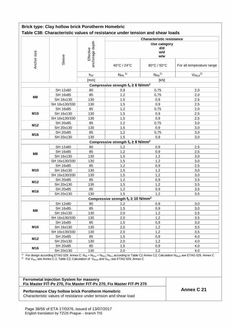
Brick type: Clay hollow brick Porotherm Homebric Table C38: Characteristic values of resistance unde r tension and shear loads
Anc
hor
size
Sle
eve
Effe
ctiv
e an
chor
age
dept
h Characteristic resistance
Use category d/d w/d w/w
40°C / 24°C 80°C / 50°C
For all temperature range
hef NRk 1) NRk
1) VRk,b2)
[mm] [kN]
Compressive strength fb ≥ 6 N/mm 2
M8
SH 12x80 80 0,9 0,75 2,0 SH 16x85 85 1,2 0,75 2,0
SH 16x130 130 1,5 0,9 2,5 SH 16x130/330 130 1,5 0,9 2,5
M10 SH 16x85 85 1,2 0,75 2,0
SH 16x130 130 1,5 0,9 2,5 SH 16x130/330 130 1,5 0,9 2,5
M12 SH 20x85 85 1,2 0,75 3,0
SH 20x130 130 1,5 0,9 3,0
M16 SH 20x85 85 1,2 0,75 3,0
SH 20x130 130 1,5 0,9 3,0 Compressive strength fb ≥ 8 N/mm 2
M8
SH 12x80 80 1,2 0,9 2,5 SH 16x85 85 1,2 0,9 2,5
SH 16x130 130 1,5 1,2 3,0 SH 16x130/330 130 1,5 1,2 3,0
M10 SH 16x85 85 1,2 0,9 2,5
SH 16x130 130 1,5 1,2 3,0 SH 16x130/330 130 1,5 1,2 3,0
M12 SH 20x85 85 1,2 0,9 3,5
SH 20x130 130 1,5 1,2 3,5
M16 SH 20x85 85 1,2 0,9 3,5
SH 20x130 130 1,5 1,2 3,5 Compressive strength fb ≥ 10 N/mm 2
M8
SH 12x80 80 1,2 0,9 3,0 SH 16x85 85 1,5 0,9 3,0
SH 16x130 130 2,0 1,2 3,5 SH 16x130/330 130 2,0 1,2 3,5
M10 SH 16x85 85 1,5 0,9 3,0
SH 16x130 130 2,0 1,2 3,5 SH 16x130/330 130 2,0 1,2 3,5
M12 SH 20x85 85 1,5 0,9 4,0
SH 20x130 130 2,0 1,2 4,0
M16 SH 20x85 85 1,5 0,9 4,0
SH 20x130 130 2,0 1,2 4,0 1) For design according ETAG 029, Annex C: NRk = NRk,p = NRk,b; NRk,s according to Table C2 Annex C2; Calculation NRk,pb see ETAG 029, Annex C 2) For VRk,s see Annex C 2, Table C2; Calculation of VRk,pb and VRk,c see ETAG 029, Annex C
Ferrometal Injection System for masonry Fix Master FIT-Pe 270, Fix Master FIT-Px 270, Fix M aster FIT-Pt 270
Annex C 21 Performance Clay hollow brick Porotherm Homebric Characteristic values of resistance under tension and shear load
Page 39/56 of ETA 17/0376, issued of 13/07/2017 English translation by TZÚS Prague – branch TIS
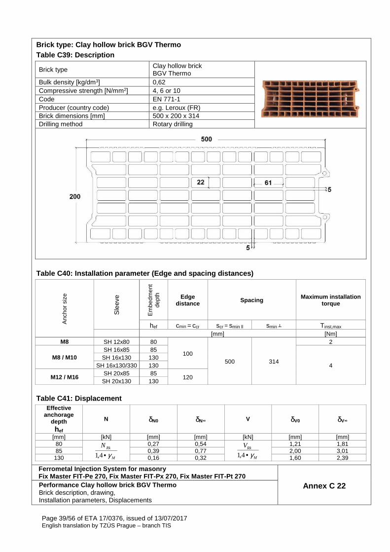
Brick type: Clay hollow brick BGV Thermo Table C39: Description
Brick type Clay hollow brick BGV Thermo
Bulk density [kg/dm3] 0,62 Compressive strength [N/mm2] 4, 6 or 10 Code EN 771-1 Producer (country code) e.g. Leroux (FR) Brick dimensions [mm] 500 x 200 x 314 Drilling method Rotary drilling
Table C40: Installation parameter (Edge and spacing distances)
Anc
hor
size
Sle
eve
Em
bedm
ent
dept
h Edge distance Spacing Maximum installation
torque
hef cmin = ccr scr = smin ll smin ┴ Tinst,max [mm] [Nm]
M8 SH 12x80 80
100 500 314
2
M8 / M10 SH 16x85 85
4 SH 16x130 130
SH 16x130/330 130
M12 / M16 SH 20x85 85
120 SH 20x130 130
Table C41: Displacement Effective
anchorage depth hef
N δN0 δN∞ V δV0 δV∞
[mm] [kN] [mm] [mm] [kN] [mm] [mm] 80
M
RkN
γ•4,1
0,27 0,54
M
RkV
γ•4,1
1,21 1,81 85 0,39 0,77 2,00 3,01
130 0,16 0,32 1,60 2,39
Ferrometal Injection System for masonry Fix Master FIT-Pe 270, Fix Master FIT-Px 270, Fix M aster FIT-Pt 270
Annex C 22 Performance Clay hollow brick BGV Thermo Brick description, drawing, Installation parameters, Displacements
Page 40/56 of ETA 17/0376, issued of 13/07/2017 English translation by TZÚS Prague – branch TIS
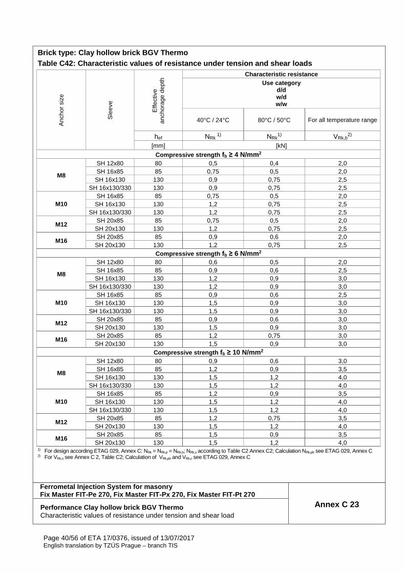
Brick type: Clay hollow brick BGV Thermo Table C42: Characteristic values of resistance unde r tension and shear loads
Anc
hor
size
Sle
eve
Effe
ctiv
e an
chor
age
dept
h Characteristic resistance
Use category d/d w/d w/w
40°C / 24°C 80°C / 50°C
For all temperature range
hef NRk 1) NRk
1) VRk,b2)
[mm] [kN]
Compressive strength fb ≥ 4 N/mm 2
M8
SH 12x80 80 0,5 0,4 2,0 SH 16x85 85 0,75 0,5 2,0
SH 16x130 130 0,9 0,75 2,5 SH 16x130/330 130 0,9 0,75 2,5
M10 SH 16x85 85 0,75 0,5 2,0
SH 16x130 130 1,2 0,75 2,5 SH 16x130/330 130 1,2 0,75 2,5
M12 SH 20x85 85 0,75 0,5 2,0
SH 20x130 130 1,2 0,75 2,5
M16 SH 20x85 85 0,9 0,6 2,0
SH 20x130 130 1,2 0,75 2,5 Compressive strength fb ≥ 6 N/mm 2
M8
SH 12x80 80 0,6 0,5 2,0 SH 16x85 85 0,9 0,6 2,5
SH 16x130 130 1,2 0,9 3,0 SH 16x130/330 130 1,2 0,9 3,0
M10 SH 16x85 85 0,9 0,6 2,5
SH 16x130 130 1,5 0,9 3,0 SH 16x130/330 130 1,5 0,9 3,0
M12 SH 20x85 85 0,9 0,6 3,0
SH 20x130 130 1,5 0,9 3,0
M16 SH 20x85 85 1,2 0,75 3,0
SH 20x130 130 1,5 0,9 3,0 Compressive strength fb ≥ 10 N/mm 2
M8
SH 12x80 80 0,9 0,6 3,0 SH 16x85 85 1,2 0,9 3,5
SH 16x130 130 1,5 1,2 4,0 SH 16x130/330 130 1,5 1,2 4,0
M10 SH 16x85 85 1,2 0,9 3,5
SH 16x130 130 1,5 1,2 4,0 SH 16x130/330 130 1,5 1,2 4,0
M12 SH 20x85 85 1,2 0,75 3,5
SH 20x130 130 1,5 1,2 4,0
M16 SH 20x85 85 1,5 0,9 3,5
SH 20x130 130 1,5 1,2 4,0 1) For design according ETAG 029, Annex C: NRk = NRk,p = NRk,b; NRk,s according to Table C2 Annex C2; Calculation NRk,pb see ETAG 029, Annex C 2) For VRk,s see Annex C 2, Table C2; Calculation of VRk,pb and VRk,c see ETAG 029, Annex C
Ferrometal Injection System for masonry Fix Master FIT-Pe 270, Fix Master FIT-Px 270, Fix M aster FIT-Pt 270
Annex C 23 Performance Clay hollow brick BGV Thermo Characteristic values of resistance under tension and shear load
Page 41/56 of ETA 17/0376, issued of 13/07/2017 English translation by TZÚS Prague – branch TIS
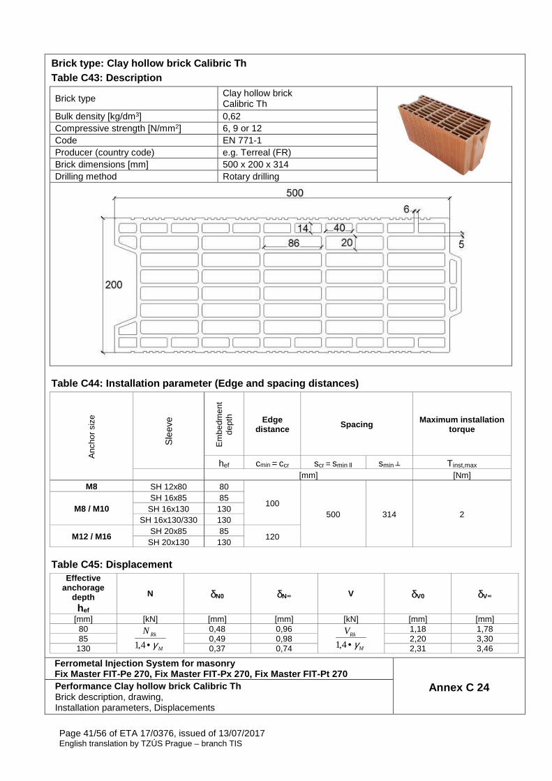
Brick type: Clay hollow brick Calibric Th Table C43: Description
Brick type Clay hollow brick Calibric Th
Bulk density [kg/dm3] 0,62 Compressive strength [N/mm2] 6, 9 or 12 Code EN 771-1 Producer (country code) e.g. Terreal (FR) Brick dimensions [mm] 500 x 200 x 314 Drilling method Rotary drilling
Table C44: Installation parameter (Edge and spacing distances)
Anc
hor
size
Sle
eve
Em
bedm
ent
dept
h Edge distance Spacing Maximum installation
torque
hef cmin = ccr scr = smin ll smin ┴ Tinst,max [mm] [Nm]
M8 SH 12x80 80
100 500 314 2
M8 / M10 SH 16x85 85
SH 16x130 130 SH 16x130/330 130
M12 / M16 SH 20x85 85
120 SH 20x130 130
Table C45: Displacement Effective
anchorage depth hef
N δN0 δN∞ V δV0 δV∞
[mm] [kN] [mm] [mm] [kN] [mm] [mm] 80
M
RkN
γ•4,1
0,48 0,96
M
RkV
γ•4,1
1,18 1,78 85 0,49 0,98 2,20 3,30
130 0,37 0,74 2,31 3,46
Ferrometal Injection System for masonry Fix Master FIT-Pe 270, Fix Master FIT-Px 270, Fix M aster FIT-Pt 270
Annex C 24 Performance Clay hollow brick Calibric Th Brick description, drawing, Installation parameters, Displacements
Page 42/56 of ETA 17/0376, issued of 13/07/2017 English translation by TZÚS Prague – branch TIS
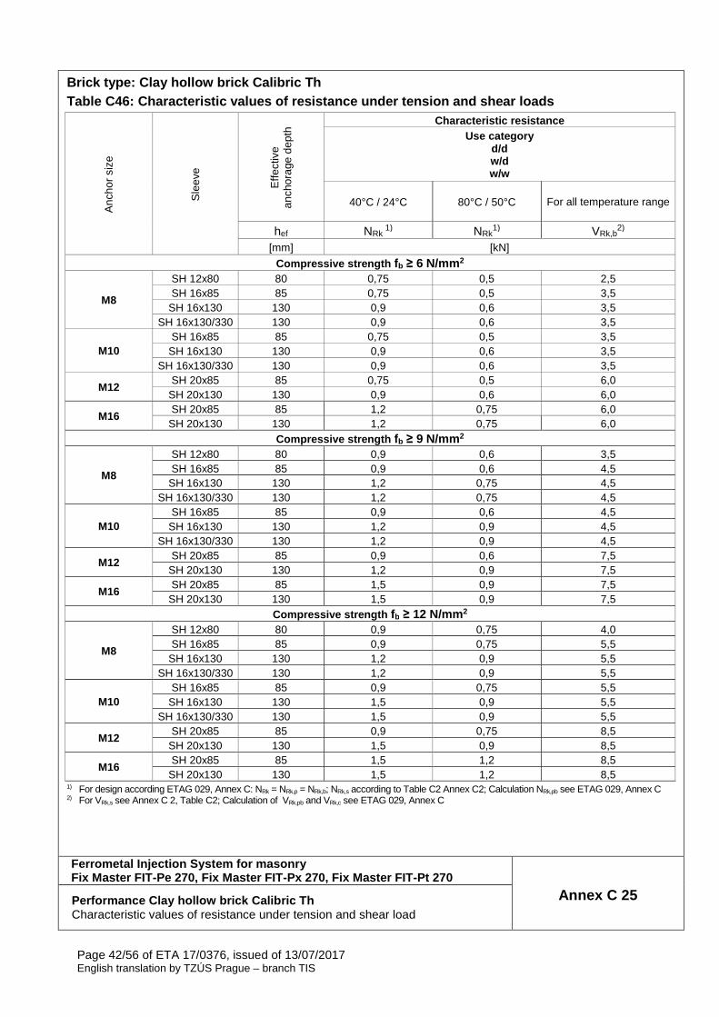
Brick type: Clay hollow brick Calibric Th Table C46: Characteristic values of resistance unde r tension and shear loads
Anc
hor
size
Sle
eve
Effe
ctiv
e an
chor
age
dept
h Characteristic resistance
Use category d/d w/d w/w
40°C / 24°C 80°C / 50°C
For all temperature range
hef NRk 1) NRk
1) VRk,b2)
[mm] [kN]
Compressive strength fb ≥ 6 N/mm 2
M8
SH 12x80 80 0,75 0,5 2,5 SH 16x85 85 0,75 0,5 3,5
SH 16x130 130 0,9 0,6 3,5 SH 16x130/330 130 0,9 0,6 3,5
M10 SH 16x85 85 0,75 0,5 3,5
SH 16x130 130 0,9 0,6 3,5 SH 16x130/330 130 0,9 0,6 3,5
M12 SH 20x85 85 0,75 0,5 6,0
SH 20x130 130 0,9 0,6 6,0
M16 SH 20x85 85 1,2 0,75 6,0
SH 20x130 130 1,2 0,75 6,0 Compressive strength fb ≥ 9 N/mm 2
M8
SH 12x80 80 0,9 0,6 3,5 SH 16x85 85 0,9 0,6 4,5
SH 16x130 130 1,2 0,75 4,5 SH 16x130/330 130 1,2 0,75 4,5
M10 SH 16x85 85 0,9 0,6 4,5
SH 16x130 130 1,2 0,9 4,5 SH 16x130/330 130 1,2 0,9 4,5
M12 SH 20x85 85 0,9 0,6 7,5
SH 20x130 130 1,2 0,9 7,5
M16 SH 20x85 85 1,5 0,9 7,5
SH 20x130 130 1,5 0,9 7,5 Compressive strength fb ≥ 12 N/mm 2
M8
SH 12x80 80 0,9 0,75 4,0 SH 16x85 85 0,9 0,75 5,5
SH 16x130 130 1,2 0,9 5,5 SH 16x130/330 130 1,2 0,9 5,5
M10 SH 16x85 85 0,9 0,75 5,5
SH 16x130 130 1,5 0,9 5,5 SH 16x130/330 130 1,5 0,9 5,5
M12 SH 20x85 85 0,9 0,75 8,5
SH 20x130 130 1,5 0,9 8,5
M16 SH 20x85 85 1,5 1,2 8,5
SH 20x130 130 1,5 1,2 8,5 1) For design according ETAG 029, Annex C: NRk = NRk,p = NRk,b; NRk,s according to Table C2 Annex C2; Calculation NRk,pb see ETAG 029, Annex C 2) For VRk,s see Annex C 2, Table C2; Calculation of VRk,pb and VRk,c see ETAG 029, Annex C
Ferrometal Injection System for masonry Fix Master FIT-Pe 270, Fix Master FIT-Px 270, Fix M aster FIT-Pt 270
Annex C 25 Performance Clay hollow brick Calibric Th Characteristic values of resistance under tension and shear load
Page 43/56 of ETA 17/0376, issued of 13/07/2017 English translation by TZÚS Prague – branch TIS
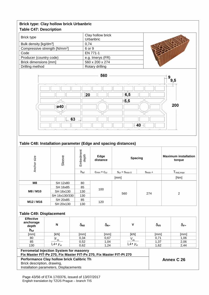
Brick type: Clay hollow brick Urbanbric Table C47: Description
Brick type Clay hollow brick Urbanbric
Bulk density [kg/dm3] 0,74 Compressive strength [N/mm2] 6 or 9 Code EN 771-1 Producer (country code) e.g. Imerys (FR) Brick dimensions [mm] 560 x 200 x 274 Drilling method Rotary drilling
Table C48: Installation parameter (Edge and spacing distances)
Anc
hor
size
Sle
eve
Em
bedm
ent
dept
h Edge distance Spacing Maximum installation
torque
hef cmin = ccr scr = smin ll smin ┴ Tinst,max [mm] [Nm]
M8 SH 12x80 80
100 560 274 2
M8 / M10 SH 16x85 85
SH 16x130 130 SH 16x130/330 130
M12 / M16 SH 20x85 85
120 SH 20x130 130
Table C49: Displacement
Effective anchorage
depth hef
N δN0 δN∞ V δV0 δV∞
[mm] [kN] [mm] [mm] [kN] [mm] [mm] 80
M
RkN
γ•4,1
0,34 0,67
M
RkV
γ•4,1
0,71 1,06 85 0,52 1,04 1,37 2,06
130 0,62 1,24 1,62 2,44
Ferrometal Injection System for masonry Fix Master FIT-Pe 270, Fix Master FIT-Px 270, Fix M aster FIT-Pt 270
Annex C 26 Performance Clay hollow brick Calibric Th Brick description, drawing, Installation parameters, Displacements
Page 44/56 of ETA 17/0376, issued of 13/07/2017 English translation by TZÚS Prague – branch TIS
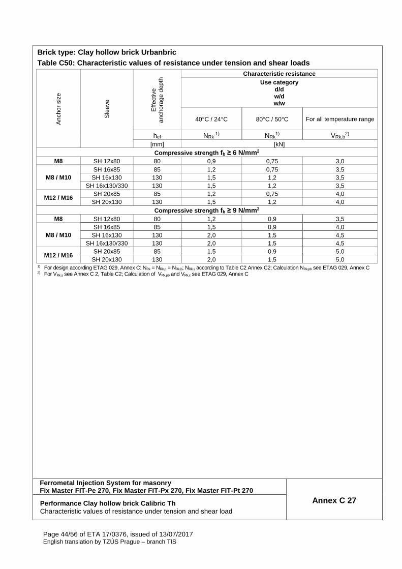
Brick type: Clay hollow brick Urbanbric Table C50: Characteristic values of resistance unde r tension and shear loads
Anc
hor
size
Sle
eve
Effe
ctiv
e an
chor
age
dept
h Characteristic resistance
Use category d/d w/d w/w
40°C / 24°C 80°C / 50°C
For all temperature range
hef NRk 1) NRk
1) VRk,b2)
[mm] [kN] Compressive strength fb ≥ 6 N/mm 2
M8 SH 12x80 80 0,9 0,75 3,0
M8 / M10 SH 16x85 85 1,2 0,75 3,5
SH 16x130 130 1,5 1,2 3,5 SH 16x130/330 130 1,5 1,2 3,5
M12 / M16 SH 20x85 85 1,2 0,75 4,0
SH 20x130 130 1,5 1,2 4,0 Compressive strength fb ≥ 9 N/mm 2
M8 SH 12x80 80 1,2 0,9 3,5
M8 / M10 SH 16x85 85 1,5 0,9 4,0
SH 16x130 130 2,0 1,5 4,5 SH 16x130/330 130 2,0 1,5 4,5
M12 / M16 SH 20x85 85 1,5 0,9 5,0
SH 20x130 130 2,0 1,5 5,0 1) For design according ETAG 029, Annex C: NRk = NRk,p = NRk,b; NRk,s according to Table C2 Annex C2; Calculation NRk,pb see ETAG 029, Annex C 2) For VRk,s see Annex C 2, Table C2; Calculation of VRk,pb and VRk,c see ETAG 029, Annex C
Ferrometal Injection System for masonry Fix Master FIT-Pe 270, Fix Master FIT-Px 270, Fix M aster FIT-Pt 270
Annex C 27 Performance Clay hollow brick Calibric Th Characteristic values of resistance under tension and shear load
Page 45/56 of ETA 17/0376, issued of 13/07/2017 English translation by TZÚS Prague – branch TIS
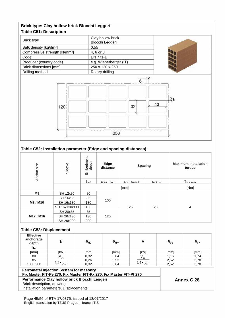
Brick type: Clay hollow brick Blocchi Leggeri Table C51: Description
Brick type Clay hollow brick Blocchi Leggeri
Bulk density [kg/dm3] 0,55 Compressive strength [N/mm2] 4, 6 or 8 Code EN 771-1 Producer (country code) e.g. Wienerberger (IT) Brick dimensions [mm] 250 x 120 x 250 Drilling method Rotary drilling
Table C52: Installation parameter (Edge and spacing distances)
Anc
hor
size
Sle
eve
Em
bedm
ent
dept
h Edge distance Spacing Maximum installation
torque
hef cmin = ccr scr = smin ll smin ┴ Tinst,max [mm] [Nm]
M8 SH 12x80 80
100
250 250 4 M8 / M10
SH 16x85 85 SH 16x130 130
SH 16x130/330 130
M12 / M16 SH 20x85 85
120 SH 20x130 130 SH 20x200 200
Table C53: Displacement Effective
anchorage depth hef
N δN0 δN∞ V δV0 δV∞
[mm] [kN] [mm] [mm] [kN] [mm] [mm] 80
M
RkN
γ•4,1
0,32 0,64
M
RkV
γ•4,1
1,16 1,74 85 0,26 0,53 2,52 3,78
130 ; 200 0,32 0,64 2,52 3,78
Ferrometal Injection System for masonry Fix Master FIT-Pe 270, Fix Master FIT-Px 270, Fix M aster FIT-Pt 270
Annex C 28 Performance Clay hollow brick Blocchi Leggeri Brick description, drawing, Installation parameters, Displacements
Page 46/56 of ETA 17/0376, issued of 13/07/2017 English translation by TZÚS Prague – branch TIS
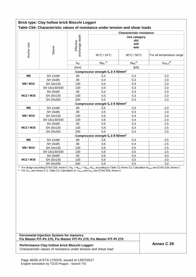
Brick type: Clay hollow brick Blocchi Leggeri Table C54: Characteristic values of resistance unde r tension and shear loads
Anc
hor
size
Sle
eve
Effe
ctiv
e an
chor
age
dept
h Characteristic resistance
Use category d/d w/d w/w
40°C / 24°C 80°C / 50°C
For all temperature range
hef NRk 1) NRk
1) VRk,b2)
[mm] [kN]
Compressive strength fb ≥ 4 N/mm 2 M8 SH 12x80 80 0,4 0,3 2,0
M8 / M10 SH 16x85 85 0,4 0,3 2,0
SH 16x130 130 0,5 0,3 2,0 SH 16x130/330 130 0,5 0,3 2,0
M12 / M16 SH 20x85 85 0,4 0,3 2,0
SH 20x130 130 0,5 0,3 2,0 SH 20x200 200 0,5 0,3 2,0
Compressive strength fb ≥ 6 N/mm 2 M8 SH 12x80 80 0,5 0,3 2,0
M8 / M10 SH 16x85 85 0,5 0,3 2,0
SH 16x130 130 0,6 0,4 2,0 SH 16x130/330 130 0,6 0,4 2,0
M12 / M16 SH 20x85 85 0,5 0,3 2,5
SH 20x130 130 0,6 0,4 2,5 SH 20x200 200 0,6 0,4 2,5
Compressive strength fb ≥ 8 N/mm 2 M8 SH 12x80 80 0,6 0,4 2,5
M8 / M10 SH 16x85 85 0,6 0,4 2,5
SH 16x130 130 0,6 0,5 2,5 SH 16x130/330 130 0,6 0,5 2,5
M12 / M16 SH 20x85 85 0,6 0,4 3,0
SH 20x130 130 0,6 0,5 3,0 SH 20x200 200 0,6 0,5 3,0
1) For design according ETAG 029, Annex C: NRk = NRk,p = NRk,b; NRk,s according to Table C2 Annex C2; Calculation NRk,pb see ETAG 029, Annex C 2) For VRk,s see Annex C 2, Table C2; Calculation of VRk,pb and VRk,c see ETAG 029, Annex C
Ferrometal Injection System for masonry Fix Master FIT-Pe 270, Fix Master FIT-Px 270, Fix M aster FIT-Pt 270
Annex C 29 Performance Clay hollow brick Blocchi Leggeri Characteristic values of resistance under tension and shear load
Page 47/56 of ETA 17/0376, issued of 13/07/2017 English translation by TZÚS Prague – branch TIS
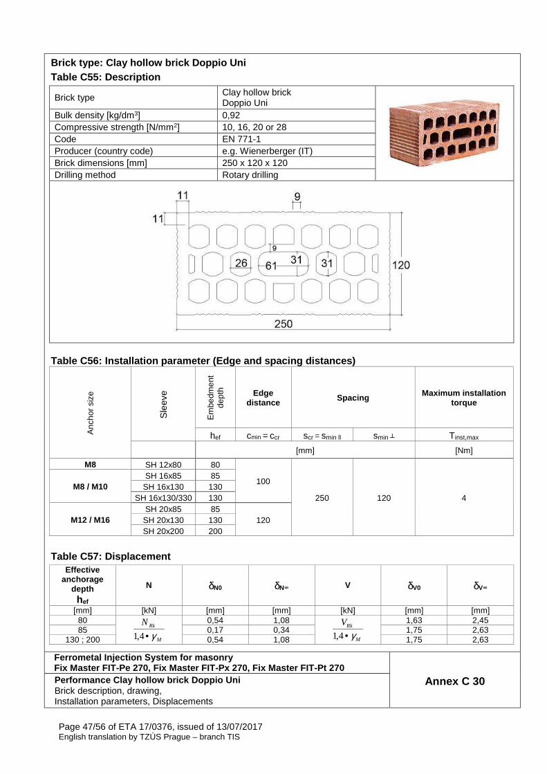
Brick type: Clay hollow brick Doppio Uni Table C55: Description
Brick type Clay hollow brick Doppio Uni
Bulk density [kg/dm3] 0,92 Compressive strength [N/mm2] 10, 16, 20 or 28 Code EN 771-1 Producer (country code) e.g. Wienerberger (IT) Brick dimensions [mm] 250 x 120 x 120 Drilling method Rotary drilling
Table C56: Installation parameter (Edge and spacing distances)
Anc
hor
size
Sle
eve
Em
bedm
ent
dept
h Edge distance Spacing Maximum installation
torque
hef cmin = ccr scr = smin ll smin ┴ Tinst,max [mm] [Nm]
M8 SH 12x80 80
100
250 120 4 M8 / M10
SH 16x85 85 SH 16x130 130
SH 16x130/330 130
M12 / M16 SH 20x85 85
120 SH 20x130 130 SH 20x200 200
Table C57: Displacement
Effective anchorage
depth hef
N δN0 δN∞ V δV0 δV∞
[mm] [kN] [mm] [mm] [kN] [mm] [mm] 80
M
RkN
γ•4,1
0,54 1,08
M
RkV
γ•4,1
1,63 2,45 85 0,17 0,34 1,75 2,63
130 ; 200 0,54 1,08 1,75 2,63
Ferrometal Injection System for masonry Fix Master FIT-Pe 270, Fix Master FIT-Px 270, Fix M aster FIT-Pt 270
Annex C 30 Performance Clay hollow brick Doppio Uni Brick description, drawing, Installation parameters, Displacements
Page 48/56 of ETA 17/0376, issued of 13/07/2017 English translation by TZÚS Prague – branch TIS
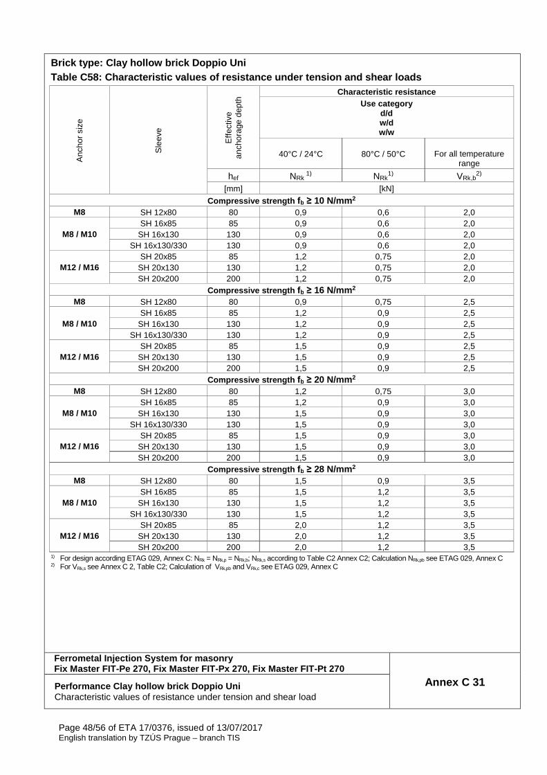
Brick type: Clay hollow brick Doppio Uni Table C58: Characteristic values of resistance unde r tension and shear loads
Anc
hor
size
Sle
eve
Effe
ctiv
e an
chor
age
dept
h Characteristic resistance
Use category d/d w/d w/w
40°C / 24°C 80°C / 50°C
For all temperature range
hef NRk 1) NRk
1) VRk,b2)
[mm] [kN]
Compressive strength fb ≥ 10 N/mm 2 M8 SH 12x80 80 0,9 0,6 2,0
M8 / M10 SH 16x85 85 0,9 0,6 2,0
SH 16x130 130 0,9 0,6 2,0 SH 16x130/330 130 0,9 0,6 2,0
M12 / M16 SH 20x85 85 1,2 0,75 2,0
SH 20x130 130 1,2 0,75 2,0 SH 20x200 200 1,2 0,75 2,0
Compressive strength fb ≥ 16 N/mm 2 M8 SH 12x80 80 0,9 0,75 2,5
M8 / M10 SH 16x85 85 1,2 0,9 2,5
SH 16x130 130 1,2 0,9 2,5 SH 16x130/330 130 1,2 0,9 2,5
M12 / M16 SH 20x85 85 1,5 0,9 2,5
SH 20x130 130 1,5 0,9 2,5 SH 20x200 200 1,5 0,9 2,5
Compressive strength fb ≥ 20 N/mm 2 M8 SH 12x80 80 1,2 0,75 3,0
M8 / M10 SH 16x85 85 1,2 0,9 3,0
SH 16x130 130 1,5 0,9 3,0 SH 16x130/330 130 1,5 0,9 3,0
M12 / M16 SH 20x85 85 1,5 0,9 3,0
SH 20x130 130 1,5 0,9 3,0 SH 20x200 200 1,5 0,9 3,0
Compressive strength fb ≥ 28 N/mm 2 M8 SH 12x80 80 1,5 0,9 3,5
M8 / M10 SH 16x85 85 1,5 1,2 3,5
SH 16x130 130 1,5 1,2 3,5 SH 16x130/330 130 1,5 1,2 3,5
M12 / M16 SH 20x85 85 2,0 1,2 3,5
SH 20x130 130 2,0 1,2 3,5 SH 20x200 200 2,0 1,2 3,5
1) For design according ETAG 029, Annex C: NRk = NRk,p = NRk,b; NRk,s according to Table C2 Annex C2; Calculation NRk,pb see ETAG 029, Annex C 2) For VRk,s see Annex C 2, Table C2; Calculation of VRk,pb and VRk,c see ETAG 029, Annex C
Ferrometal Injection System for masonry Fix Master FIT-Pe 270, Fix Master FIT-Px 270, Fix M aster FIT-Pt 270
Annex C 31 Performance Clay hollow brick Doppio Uni Characteristic values of resistance under tension and shear load
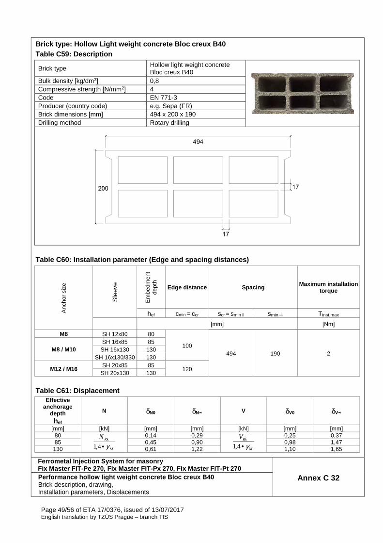
Page 49/56 of ETA 17/0376, issued of 13/07/2017 English translation by TZÚS Prague – branch TIS
Brick type: Hollow Light weight concrete Bloc creux B40 Table C59: Description
Brick type Hollow light weight concrete Bloc creux B40
Bulk density [kg/dm3] 0,8 Compressive strength [N/mm2] 4 Code EN 771-3 Producer (country code) e.g. Sepa (FR) Brick dimensions [mm] 494 x 200 x 190 Drilling method Rotary drilling
Table C60: Installation parameter (Edge and spacing distances)
Anc
hor
size
Sle
eve
Em
bedm
ent
dept
h
Edge distance Spacing Maximum installation torque
hef cmin = ccr scr = smin ll smin ┴ Tinst,max [mm] [Nm]
M8 SH 12x80 80
100 494 190 2
M8 / M10 SH 16x85 85
SH 16x130 130 SH 16x130/330 130
M12 / M16 SH 20x85 85
120 SH 20x130 130
Table C61: Displacement
Effective anchorage
depth hef
N δN0 δN∞ V δV0 δV∞
[mm] [kN] [mm] [mm] [kN] [mm] [mm] 80
M
RkN
γ•4,1
0,14 0,29
M
RkV
γ•4,1
0,25 0,37 85 0,45 0,90 0,98 1,47
130 0,61 1,22 1,10 1,65
Ferrometal Injection System for masonry Fix Master FIT-Pe 270, Fix Master FIT-Px 270, Fix M aster FIT-Pt 270
Annex C 32 Performance hollow light weight concrete Bloc creux B40 Brick description, drawing, Installation parameters, Displacements
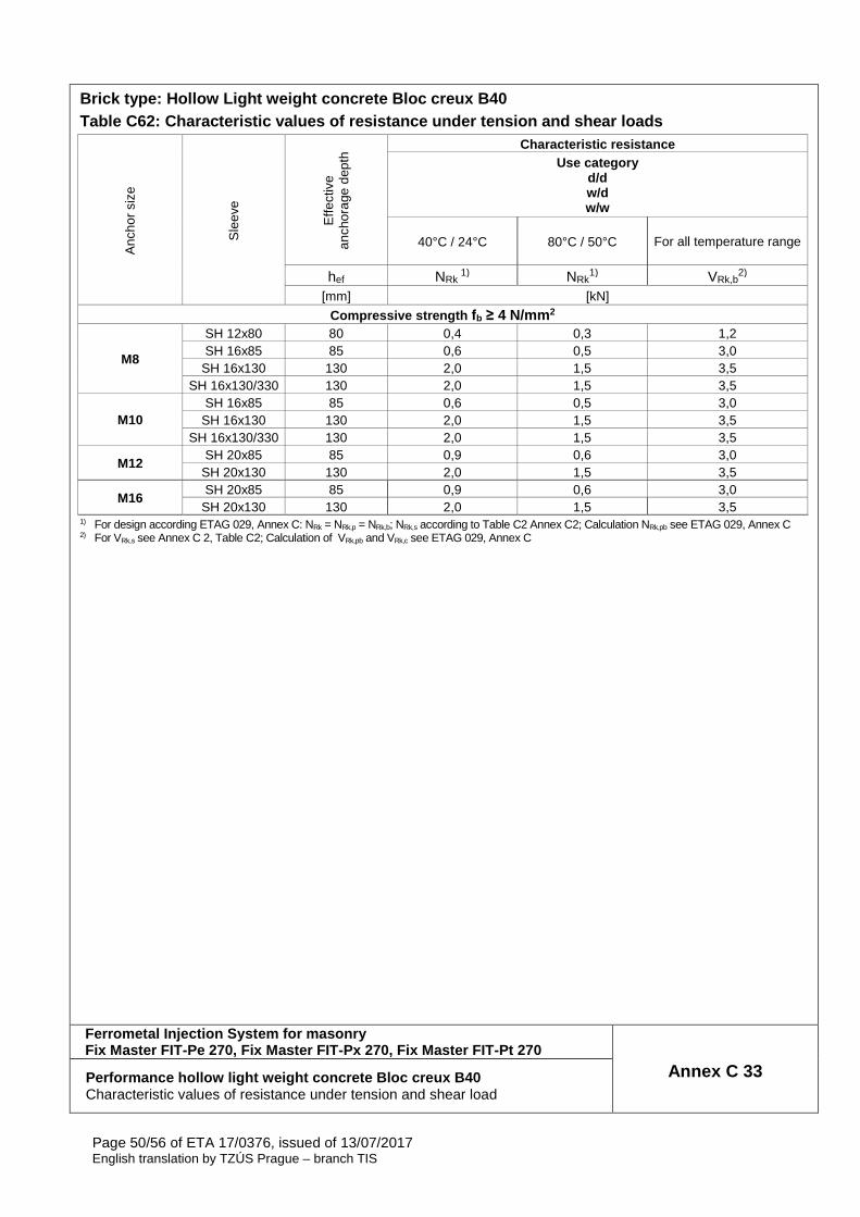
Page 50/56 of ETA 17/0376, issued of 13/07/2017 English translation by TZÚS Prague – branch TIS
Brick type: Hollow Light weight concrete Bloc creux B40 Table C62: Characteristic values of resistance unde r tension and shear loads
Anc
hor
size
Sle
eve
Effe
ctiv
e an
chor
age
dept
h Characteristic resistance
Use category d/d w/d w/w
40°C / 24°C 80°C / 50°C
For all temperature range
hef NRk 1) NRk
1) VRk,b2)
[mm] [kN]
Compressive strength fb ≥ 4 N/mm 2
M8
SH 12x80 80 0,4 0,3 1,2 SH 16x85 85 0,6 0,5 3,0
SH 16x130 130 2,0 1,5 3,5 SH 16x130/330 130 2,0 1,5 3,5
M10 SH 16x85 85 0,6 0,5 3,0
SH 16x130 130 2,0 1,5 3,5 SH 16x130/330 130 2,0 1,5 3,5
M12 SH 20x85 85 0,9 0,6 3,0
SH 20x130 130 2,0 1,5 3,5
M16 SH 20x85 85 0,9 0,6 3,0
SH 20x130 130 2,0 1,5 3,5 1) For design according ETAG 029, Annex C: NRk = NRk,p = NRk,b; NRk,s according to Table C2 Annex C2; Calculation NRk,pb see ETAG 029, Annex C 2) For VRk,s see Annex C 2, Table C2; Calculation of VRk,pb and VRk,c see ETAG 029, Annex C
Ferrometal Injection System for masonry Fix Master FIT-Pe 270, Fix Master FIT-Px 270, Fix M aster FIT-Pt 270
Annex C 33 Performance hollow light weight concrete Bloc creux B40 Characteristic values of resistance under tension and shear load

Page 51/56 of ETA 17/0376, issued of 13/07/2017 English translation by TZÚS Prague – branch TIS
Brick type: Solid light weight concrete brick Table C63: Description
Brick type Solid light weight concrete brick
Bulk density [kg/dm3] 0,63 Compressive strength [N/mm2] 2 Code EN 771-3 Producer (country code) e.g. Bisotherm (DE) Brick dimensions [mm] 300 x 123 x 248 Drilling method Rotary drilling
Table C64: Installation parameter (Edge and spacing distances)
Anc
hor
size
Sle
eve
Em
bedm
ent
dept
h
Edge distance Spacing Maximum installation torque
hef cmin = ccr scr = smin ll = smin ┴ Tinst,max [mm] [Nm]
M8 - 80 120 240 6
M10 - 90 135 270 M12 - 100 150 300 10 M16 - 100 150 300 14
Table C65: Displacement
Effective anchorage
depth hef
N δN0 δN∞ V δV0 δV∞
[mm] [kN] [mm] [mm] [kN] [mm] [mm] 80
M
RkN
γ•4,1
0,64 1,28
M
RkV
γ•4,1
0,50 0,75 90 0,70 1,41 0,68 1,03
100 0,21 0,42 0,54 0,81
Ferrometal Injection System for masonry Fix Master FIT-Pe 270, Fix Master FIT-Px 270, Fix M aster FIT-Pt 270
Annex C 34 Performance Solid light weight concrete LAC Brick description, drawing, Installation parameters, Displacements
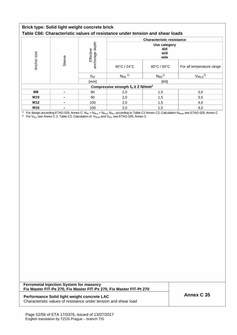
Page 52/56 of ETA 17/0376, issued of 13/07/2017 English translation by TZÚS Prague – branch TIS
Brick type: Solid light weight concrete brick Table C66: Characteristic values of resistance unde r tension and shear loads
Anc
hor
size
Sle
eve
Effe
ctiv
e an
chor
age
dept
h Characteristic resistance
Use category d/d w/d w/w
40°C / 24°C 80°C / 50°C
For all temperature range
hef NRk 1) NRk
1) VRk,b2)
[mm] [kN]
Compressive strength fb ≥ 2 N/mm 2 M8 - 80 2,0 1,5 3,0
M10 - 90 2,0 1,5 3,5 M12 - 100 2,0 1,5 4,0 M16 - 100 2,0 1,5 4,0
1) For design according ETAG 029, Annex C: NRk = NRk,p = NRk,b; NRk,s according to Table C2 Annex C2; Calculation NRk,pb see ETAG 029, Annex C 2) For VRk,s see Annex C 2, Table C2; Calculation of VRk,pb and VRk,c see ETAG 029, Annex C
Ferrometal Injection System for masonry Fix Master FIT-Pe 270, Fix Master FIT-Px 270, Fix M aster FIT-Pt 270
Annex C 35 Performance Solid light weight concrete LAC Characteristic values of resistance under tension and shear load
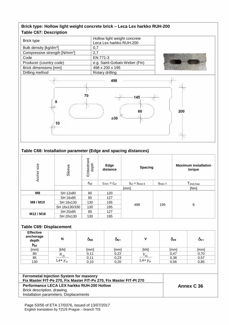
Page 53/56 of ETA 17/0376, issued of 13/07/2017 English translation by TZÚS Prague – branch TIS
Brick type: Hollow light weight concrete brick – Le ca Lex harkko RUH-200 Table C67: Description
Brick type Hollow light weight concrete Leca Lex harkko RUH-200
Bulk density [kg/dm3] 0,7 Compressive strength [N/mm2] 2,7 Code EN 771-3 Producer (country code) e.g. Saint-Gobain Weber (Fin) Brick dimensions [mm] 498 x 200 x 195 Drilling method Rotary drilling
Table C68: Installation parameter (Edge and spacing distances)
Anc
hor
size
Sle
eve
Em
bedm
ent
dept
h Edge distance Spacing Maximum installation
torque
hef cmin = ccr scr = smin ll smin ┴ Tinst,max [mm] [Nm]
M8 SH 12x80 80 120
498 195 8 M8 / M10
SH 16x85 85 127 SH 16x130 130 195
SH 16x130/330 130 195
M12 / M16 SH 20x85 85 127
SH 20x130 130 195 Table C69: Displacement
Effective anchorage
depth hef
N δN0 δN∞ V δV0 δV∞
[mm] [kN] [mm] [mm] [kN] [mm] [mm] 80
M
RkN
γ•4,1
0,11 0,22
M
RkV
γ•4,1
0,47 0,70 85 0,11 0,23 0,38 0,57
130 0,10 0,20 0,56 0,85
Ferrometal Injection System for masonry Fix Master FIT-Pe 270, Fix Master FIT-Px 270, Fix M aster FIT-Pt 270
Annex C 36 Performance LECA LEX harkko RUH-200 Hollow Brick description, drawing, Installation parameters, Displacements
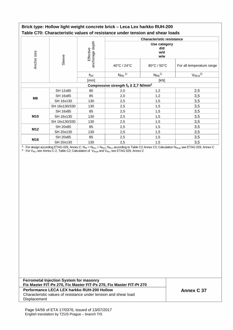
Page 54/56 of ETA 17/0376, issued of 13/07/2017 English translation by TZÚS Prague – branch TIS
Brick type: Hollow light weight concrete brick – Le ca Lex harkko RUH-200 Table C70: Characteristic values of resistance unde r tension and shear loads
Anc
hor
size
Sle
eve
Effe
ctiv
e an
chor
age
dept
h Characteristic resistance
Use category d/d w/d w/w
40°C / 24°C 80°C / 50°C
For all temperature range
hef NRk 1) NRk
1) VRk,b2)
[mm] [kN]
Compressive strength fb ≥ 2,7 N/mm 2
M8
SH 12x80 80 2,0 1,2 2,5 SH 16x85 85 2,0 1,2 3,5
SH 16x130 130 2,5 1,5 3,5 SH 16x130/330 130 2,5 1,5 3,5
M10 SH 16x85 85 2,0 1,5 3,5
SH 16x130 130 2,5 1,5 3,5 SH 16x130/330 130 2,5 1,5 3,5
M12 SH 20x85 85 2,5 1,5 3,5
SH 20x130 130 2,5 1,5 3,5
M16 SH 20x85 85 2,5 1,5 3,5
SH 20x130 130 2,5 1,5 3,5 1) For design according ETAG 029, Annex C: NRk = NRk,p = NRk,b; NRk,s according to Table C2 Annex C2; Calculation NRk,pb see ETAG 029, Annex C 2) For VRk,s see Annex C 2, Table C2; Calculation of VRk,pb and VRk,c see ETAG 029, Annex C
Ferrometal Injection System for masonry Fix Master FIT-Pe 270, Fix Master FIT-Px 270, Fix M aster FIT-Pt 270
Annex C 37 Performance LECA LEX harkko RUH-200 Hollow Characteristic values of resistance under tension and shear load Displacement
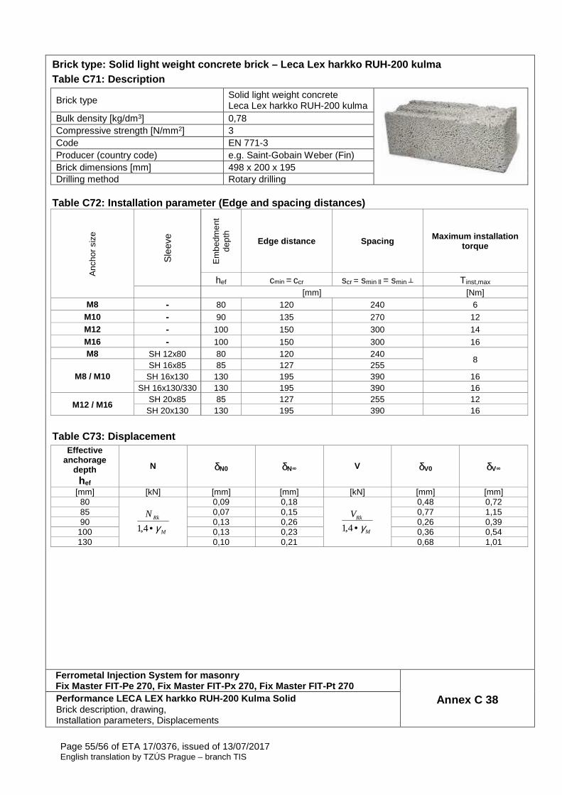
Page 55/56 of ETA 17/0376, issued of 13/07/2017 English translation by TZÚS Prague – branch TIS
Brick type: Solid light weight concrete brick – Lec a Lex harkko RUH-200 kulma Table C71: Description
Brick type Solid light weight concrete Leca Lex harkko RUH-200 kulma
Bulk density [kg/dm3] 0,78 Compressive strength [N/mm2] 3 Code EN 771-3 Producer (country code) e.g. Saint-Gobain Weber (Fin) Brick dimensions [mm] 498 x 200 x 195 Drilling method Rotary drilling
Table C72: Installation parameter (Edge and spacing distances)
Anc
hor
size
Sle
eve
Em
bedm
ent
dept
h
Edge distance Spacing Maximum installation torque
hef cmin = ccr scr = smin ll = smin ┴ Tinst,max [mm] [Nm]
M8 - 80 120 240 6 M10 - 90 135 270 12 M12 - 100 150 300 14 M16 - 100 150 300 16 M8 SH 12x80 80 120 240
8
M8 / M10 SH 16x85 85 127 255
SH 16x130 130 195 390 16 SH 16x130/330 130 195 390 16
M12 / M16 SH 20x85 85 127 255 12
SH 20x130 130 195 390 16 Table C73: Displacement
Effective anchorage
depth hef
N δN0 δN∞ V δV0 δV∞
[mm] [kN] [mm] [mm] [kN] [mm] [mm] 80
M
RkN
γ•4,1
0,09 0,18
M
RkV
γ•4,1
0,48 0,72 85 0,07 0,15 0,77 1,15 90 0,13 0,26 0,26 0,39
100 0,13 0,23 0,36 0,54 130 0,10 0,21 0,68 1,01
Ferrometal Injection System for masonry Fix Master FIT-Pe 270, Fix Master FIT-Px 270, Fix M aster FIT-Pt 270
Annex C 38 Performance LECA LEX harkko RUH-200 Kulma Solid Brick description, drawing, Installation parameters, Displacements

Page 56/56 of ETA 17/0376, issued of 13/07/2017 English translation by TZÚS Prague – branch TIS
Brick type: Solid light weight concrete brick – Lec a Lex harkko RUH-200 kulma Table C74: Characteristic values of resistance unde r tension and shear loads
Anc
hor
size
Sle
eve
Effe
ctiv
e an
chor
age
dept
h Characteristic resistance
Use category d/d w/d w/w
40°C / 24°C 80°C / 50°C
For all temperature range
hef NRk 1) NRk
1) VRk,b2)
[mm] [kN]
Compressive strength fb ≥ 3,0 N/mm 2 M8 - 80 2,0 1,2 3,0
M10 - 90 3,0 2,0 4,0 M12 - 100 3,0 2,0 4,0 M16 - 100 3,0 2,0 4,0
M8
SH 12x80 80 2,0 1,2 3,0 SH 16x85 85 2,0 1,5 3,5
SH 16x130 130 3,0 2,0 4,0 SH 16x130/330 130 3,0 2,0 4,0
M10 SH 16x85 85 2,0 1,5 3,5
SH 16x130 130 3,0 2,0 4,0 SH 16x130/330 130 3,0 2,0 4,0
M12 / M16 SH 20x85 85 2,0 1,5 4,5
SH 20x130 130 3,0 2,0 4,5 1) For design according ETAG 029, Annex C: NRk = NRk,p = NRk,b; NRk,s according to Table C2 Annex C2; Calculation NRk,pb see ETAG 029, Annex C 2) For VRk,s see Annex C 2, Table C2; Calculation of VRk,pb and VRk,c see ETAG 029, Annex C
Ferrometal Injection System for masonry Fix Master FIT-Pe 270, Fix Master FIT-Px 270, Fix M aster FIT-Pt 270
Annex C 39 Performance LECA LEX harkko RUH-200 Kulma Solid Characteristic values of resistance under tension and shear load
Recommended