Master’s Thesis
Evaluation of a Set of TCP Features over
Narrowband Radio Bearer for Train
Communication
BY
Jakub Mucha
&
Pajtim Buzolli
Department of Electrical and Information Technology
Faculty of Engineering, LTH, Lund University
SE-221 00 Lund, Sweden 2015

- 2 -
- 3 -
ABSTRACT
An engineering approach to the evaluation of the TCP as a narrowband bearer for short messages in the
low latency train-trackside communication scenario is described in this report. The project was
developed in cooperation with Bombardier Transportation Sweden AB as a part of the “ETCS over
GPRS” venture.
With the increase of the demands from the railway industry, the currently used circuit-switched GSM-
R technology becomes unsatisfactory from the radio system capacity point of view and the need of a
new solution is highly required. The packet-switched GPRS solution using TCP as a suite is under
research for this specific scenario. The investigated problem in this report concerns the tuning of the
retransmission mechanism, which includes the TCP features TCP_RTO_MIN and TCP_KEEPALIVE.
This implies the tuning of those features to be able to detect a loss of communication and to react less
aggressively for the short and instantaneous changes in the network delay.
This thesis work began with a preparation phase in which a broad literature analysis of the background
theory was made and followed by the development of applications that realizes the traffic model. Later
in the performance phase the required changes were applied on the system and finally tested in a lab.
The tests have been performed using one and four pairs of client-server applications communicating
over an emulated link. The TCP features were modified at two levels, the TCP_RTO_MIN by a kernel
recompilation and the TCP_KEEPALIVE by changes on the live system. Results from the tests have
shown that for the higher than the default value of the TCP_RTO_MIN the less retransmissions were
triggered. The TCP_KEEPALIVE has proven to be a sufficient feature to indicate a loss of the link.
However the achieved improvement in performance was not as high as expected, but acceptable for this
scenario. The train-trackside communication system could benefit from the proposed changes.

- 4 -
- 5 -
POPULAR SCIENTIFIC ARTICLE The point of this thesis was to evaluate the modifications of transmission control protocol (TCP), the
most common transmission control protocol in the Internet, for an operation in a specific scenario.
Similar to a diplomatic protocol, which defines the rules for each separate activity for relations in the
field of diplomacy, TCP does the same for a digital communication over the world’s biggest network,
Internet or as it is sometime called World Wide Web. The functionality of TCP was formed to support
the communication over a wired network. Later, when cellular communication systems like GSM started
to conquer the world, it was a natural step forward to introduce TCP to a wireless environment. One
main problem was addressed: how to make TCP to work well in a wireless environment? TCP was
offered for the mobile phones first using a circuit-switched technology, where two network points
establish a dedicated communication channel (circuit) before the communication starts. Later it started
using a packet-switching technology, where the information is divided and stored in separate small data-
containers (packets) that can be transmitted individually allowing to establish multiple communication
sessions over one medium. This technology was implemented in GPRS, a successor of GSM. When the
first GPRS service was launched publically providing the packet-switched Internet for a mobile phones,
the railway industry was finishing the GSM-R specification. GSM-R (GSM for Railways) is a
communication system that allows to organize and control the train traffic by using a radio interface
instead of optical signals, where each train is governed by its corresponding control center. This solution
improved greatly the offered service seen as a number of trains per hour in a certain area (system
capacity). During the last 15 years the telecommunication standards have evolved from GSM up to
modern solutions, but until present day only GSM-R technology has been used by the railway industry.
Nowadays, the growth of the railway infrastructure has ultimately led to a situation where the circuit-
switched technology is insufficient from the radio system capacity aspect, which is hindering the further
development of the railway infrastructure. It means that the physical architecture could support more
trains on the tracks but the current, radio-based train control system (GSM-R) has no more resources for
upgrade. Because of that problem the European Railway Agency has chosen GPRS as the solution,
utilizing TCP as the communication protocol. If we compare this to diplomacy, if I want to share a
certain information with the British Queen I will speak English and the diplomatic protocol will help
me to choose proper words. In a similar manner GPRS will define the technology for communication
and TCP will tell what rules that technology should follow. At this point the main problem of our thesis
could be introduced: how to modify TCP to make it suitable for a train control system over a wireless
link? First thing that we had to change in TCP was its reliability feature (retransmission mechanism).
When one endpoint sends data to another, the other has to acknowledge a successful reception by
sending ACKs. If the source will not get any ACK within a specific time after sending the data is
assumed lost or damaged and it will be retransmitted. Based on the transmission properties of the
networks operating on a wire medium, the minimum time the sender will wait for ACK was estimated
to 1 s. However, a radio link has different transmission properties, i.e. much longer delays can occur,
when compared to wire-based communication. We modified this minimum waiting window to 2
seconds, making TCP more patient and reacting less aggressively to the shorter delays in the wireless
link. We ran the experiments over a simulated, wireless link using two computers communicating over
a wire-based connection via a network emulator, which imitates the radio channel characteristics. In
total our results show a decrease in number of retransmissions (system performance is improved as less
resources are used to maintain the link), but achieved progression was lower than expected. This is due
to the complexity of the TCP instructions. Second thing that we changed in TCP was the link state
monitor feature. We allowed TCP to detect a loss of communication in a much shorter amount of time
than the default. Our results provide another argument that justifies the migration towards a packet-
switched technology in the train industry and could potentially be implemented as a part of this venture.

- 6 -

- 7 -
ACKNOWLEDGEMENTS
First of all we would like to show our deep gratitude to our supervisors Jens A. Andersson and Stefan
Höst for their interest and patience during the progress of the entire thesis. Without their support and
invaluable guidance we would not be able to achieve the final goals. Subsequently we would like to
thank our thesis examiner Maria Kihl for her evaluation and suggestions over the report. In addition we
are both profoundly thankful to our supervisors Jörgen Mattisson, Neil Freeman and the other staff
members of Bombardier in Hässleholm for all the experience shared, problems solved and feedback
provided during the period of the last months. Last but not least, we have to show our deep appreciation
to our families whose faith allowed us to overcome all the minor and major obstacles.
AUTHORS
Jakub Mucha [email protected]
Pajtim Buzolli [email protected]
SUPERVISORS
Jörgen Mattisson [email protected]
Neil Freeman [email protected]
Jens A. Andersson [email protected]
Stefan Höst [email protected]
EXAMINER
Maria Kihl [email protected]
THESIS START 2015-01-19
THESIS PRESENTATIONS
Bombardier 2015-10-13
LTH 2015-12-18

- 8 -

- 9 -
PREFACE
This master’s thesis was performed for the Department of Electrical and Information Technology of
Lund University and Bombardier Transportation AB. The project was conducted at the Bombardier
facility in Hässleholm by Jakub Mucha and Pajtim Buzolli between January and October of 2015.
The workload was distributed equally between us as we were closely cooperating over the entire
duration of the project. The only worth distinction to mention is that Jakub were more responsible for
the TCP part while Pajtim put more attention to the GSM-R/GPRS section.

- 10 -
- 11 -
ACRONYMS
A ACK - ACKnowledgement
AR - Authentication Response
AU - AUthentication
AuC - Authentication Center
B BER - Bit Error Rate
BS - Base Station
BSC - Base Station Controllers
BSS - Base Station Subsystem
BSSGP - Base Station System GPRS Protocol
BTS - Base Transceiver Stations
C cwnd - congestion window
CS - Circuit Switched
D DI - DIsconnect
DL - DownLink (Trackside → Train)
DNS - Domain Name System
E EIR - Equipment Identity Register
eMLPP - enhanced MultiLevel Precedence & Preemption service
ENIF - ERTMS National Integration Fund
EoG - ETCS over GPRS
ERA - European Railway Agency
ERTMS - European Rail Traffic Management System
ETCS - European Train Control System
EU - European Union
F FEC - Forward Error Correction
G GGSN - Gateway GPRS Support Node
GM - General Message
GMM - GPRS Mobility Management
GMSC - Gateway Mobile Switching Center
GPRS - General Packet Radio Service
GUI - Graphical User Interface
GTP - GPRS Tunneling Protocol
H HLR - Home Location Register
I IMSI - International Mobile Subscriber Identity
IP - Internet Protocol
I-TCP - Indirect TCP
- 12 -
L LA - Local Area
LLC - Logical Link Control
LTE - Long Term Evolution
M MA - Movement Authority
MAC - Medium Access Control
MM - Mobility Management
MO - Mobile Originated
MS - Mobile Station
MSS - Maximum Segment Size
MSC - Mobile Switching Center
MT - Mobile Terminated
M-TCP - Mobile-TCP
N NSAPI - Network Service Access Point
NSS - Network Switching Subsystem
O OBU - On-Board Unit (Train)
OS - Operating System
P PDCH - Packet Data CHannel
PDN - Packet Data Network
PDP - Packet Data Protocol
PDU - Packet Data Unit
PIN - Personal Identification Number
POS - POSition report
PS - Packet Switched
PTM - Point-To-Multipoint
PTM-M - PTM-Multicast
PTM-G - PTM-Group call
PTP - Point-To-Point
PTP-CLNS - PTP-Connectionless Network Service
PTP-CONS - PTP-Connection Oriented Network Service
Q QoS - Quality of Service
R RA - Routeing Area
RBC - Radio Block Controller
REC - Railway Emergency Call
RF - Radio Frequency
RFC – Ready For Comment
RLC - Radio Link Control
RTD - Round Trip Delay
RTO - Retransmission TimeOut
RTT - Round Trip Time
RTTVAR - Round Trip Time VARiance

- 13 -
S SA - Service Area
SAN - Storage Area Network
SR-ARQ - Selective Repeat Automatic Repeat reQuest
SGSN - Serving GPRS Support Node
SM - Session Management
SNDCP – Sub-Network Dependent Convergence Protocol
SRTT - Smoothed Round Trip Time
ssthresh - slow start threshold
T TCP - Transmission Control Protocol
TDMA - Time Division Multiple Access
TID - Tunneling IDentifier
TLLI - Tunneling Logical Link Identifier
U UIC – Union Internationale des Chemins de fer
UL - UpLink (Train → Trackside)
UMTS - Universal Mobile Telecommunication System
UNISIG - UNIon of SIGnalling industry
V VBS - Voice Broadcast Service
VLR - Visitor Location Register
VGCS - Voice Group Call Service
W WAN - Wide Area Network
WANem - Wide Area Network emulator

- 14 -
- 15 -
TABLE OF CONTENT
Abstract ................................................................................................................................. - 3 -
Popular Scientific Article ...................................................................................................... - 5 -
Acknowledgements ............................................................................................................... - 7 -
Preface ................................................................................................................................... - 9 -
Acronyms ............................................................................................................................ - 11 -
Table of Content .................................................................................................................. - 15 -
CHAPTER 1 Introduction ................................................................................................... - 17 -
1.1 Background ............................................................................................................... - 17 -
1.2 Problem Description .................................................................................................. - 17 -
1.3 Purpose ...................................................................................................................... - 18 -
1.4 Method ...................................................................................................................... - 18 -
1.5 Scope ......................................................................................................................... - 18 -
1.6 Report Layout ............................................................................................................ - 19 -
CHAPTER 2 Theory ........................................................................................................... - 21 -
2.1 Introduction ............................................................................................................... - 21 -
2.2 GSM-R ...................................................................................................................... - 21 -
2.2.1 GSM-R Services ................................................................................................. - 22 -
2.2.2 GSM Drawbacks ................................................................................................ - 24 -
2.3 GPRS ......................................................................................................................... - 24 -
2.3.1 GPRS Architecture ............................................................................................. - 25 -
2.3.2 GPRS Services ................................................................................................... - 25 -
2.3.3 GPRS Service Areas ........................................................................................... - 26 -
2.3.4 GPRS Terminals ................................................................................................. - 26 -
2.3.5 GPRS Transmission & Signaling Planes ........................................................... - 27 -
2.3.6 GPRS Security .................................................................................................... - 27 -
2.3.7 GPRS Mobility Management ............................................................................. - 28 -
2.3.8 GPRS End-to-End Packet Routing ..................................................................... - 31 -
2.3.9 GPRS Coding Schemes ...................................................................................... - 32 -
2.4 ETCS over GPRS ...................................................................................................... - 32 -
2.5 TCP ............................................................................................................................ - 33 -
2.5.1 Core Functionality .............................................................................................. - 33 -
2.5.2 Congestion Control Strategy .............................................................................. - 34 -
2.5.3 RTO .................................................................................................................... - 36 -
2.5.4 TCP_RTO_MIN ................................................................................................. - 37 -
- 16 -
2.5.5 TCP_KEEPALIVE ............................................................................................. - 38 -
2.6 Related Works ........................................................................................................... - 39 -
2.7 Traffic Model ............................................................................................................ - 40 -
2.7.1 ETCS Start-up Session ....................................................................................... - 41 -
2.7.2 Level-2 Session .................................................................................................. - 41 -
CHAPTER 3 System Description ....................................................................................... - 45 -
3.1 Test Applications ....................................................................................................... - 45 -
3.2 Testbed ...................................................................................................................... - 45 -
CHAPTER 4 Experiments .................................................................................................. - 47 -
4.1 Experiment Organization .......................................................................................... - 47 -
4.2 TCP_RTO_MIN ........................................................................................................ - 47 -
4.3 TCP_KEEPALIVE .................................................................................................... - 48 -
4.4 Test Groups ............................................................................................................... - 48 -
CHAPTER 5 Results & Discussion .................................................................................... - 51 -
5.1 Test Results ............................................................................................................... - 51 -
5.1.1 Test Group #0 ..................................................................................................... - 51 -
5.1.2 Test Group #1 ..................................................................................................... - 52 -
5.1.3 Test Group #2 ..................................................................................................... - 55 -
5.1.4 Test Group #3 ..................................................................................................... - 57 -
5.2 Discussion ................................................................................................................. - 60 -
5.2.1 Test Group #0 ..................................................................................................... - 60 -
5.2.2 Test Group #1 ..................................................................................................... - 60 -
5.2.3 Test Group #2 ..................................................................................................... - 61 -
5.2.4 Test Group #3 ..................................................................................................... - 62 -
CHAPTER 6 Report Closure .............................................................................................. - 63 -
6.1 Conclusions ............................................................................................................... - 63 -
6.1.1 TCP_RTO_MIN ................................................................................................. - 63 -
6.1.2 TCP_KEEPALIVE ............................................................................................. - 64 -
6.1.3 General ............................................................................................................... - 64 -
6.2 Future Work .............................................................................................................. - 65 -
References ........................................................................................................................... - 67 -
APPENDIX A Test Case Tables ......................................................................................... - 71 -
- 17 -
CHAPTER 1 INTRODUCTION
1.1 BACKGROUND
The point of this thesis was to evaluate the modifications of the transmission control protocol (TCP),
the most common transmission control protocol in Internet, for an operation in a specific scenario.
Similar to a diplomatic protocol, which defines the rules for each separate activity for relations in the
field of diplomacy, TCP does the same for a digital communication over the world’s biggest network,
Internet or as it is sometimes called World Wide Web. The functionality of TCP was formed to support
the communication over a wired network. Later, when cellular communication systems like GSM started
to conquer the world, it was a natural step forward to introduce TCP to a wireless environment. One
main problem was addressed: how to make TCP to work well in a wireless environment? TCP was
offered for the mobile phones first using a circuit-switched technology, where two network points
establish a dedicated communication channel (circuit) before the communication starts. Later it started
using a packet-switching technology, where the information is divided and stored in separate small data-
containers (packets) that can be transmitted individually allowing to establish multiple communication
sessions over one medium. This technology was implemented in GPRS, a successor of GSM. When the
first GPRS service was launched publically providing the packet-switched Internet for a mobile phones,
the railway industry was finishing the GSM-R specification. GSM-R (GSM for Railways) is a
communication system that allows to organize and control the train traffic by using a radio interface
instead of optical signals, where each train is governed by its corresponding control center. This solution
improved greatly the offered service seen as a number of trains per hour in a certain area (system
capacity). During the last 15 years the telecommunication standards have evolved from GSM up to
modern solutions, but until present day only GSM-R technology has been used by the railway industry.
Nowadays, the growth of the railway infrastructure has ultimately led to a situation where the circuit-
switched technology is insufficient from the radio system capacity aspect, which is hindering the further
development of the railway infrastructure. It means that the physical architecture could support more
trains on the tracks but the current, radio-based train control system (GSM-R) has no more resources for
upgrade. Because of that problem the European Railway Agency has chosen GPRS as the solution,
utilizing TCP as the communication protocol. If we compare this to diplomacy, if I want to share a
certain information with the British Queen I will speak English and the diplomatic protocol will help
me to choose proper words. In a similar manner GPRS will define the technology for communication
and TCP will tell what rules that technology should follow.
Bombardier Transportation with the other members of the “Union of Signaling industry” are currently
working on a venture called “ETCS over GPRS”. The purpose of this great project is to replace the
circuit-switched protocols with the packet-oriented TCP and this thesis work is responsible for the
research of some chosen TCP features.
1.2 PROBLEM DESCRIPTION
The idea of this topic was to evaluate a set of TCP features to transfer small packages with a low latency
over a narrowband bearer. The bearer is defined by a specific GPRS coding scheme, which provides a
maximum bandwidth of 12 kbps to a user. The problem addressed in this master project is a small part
of a larger venture to migrate from circuit-switched GSM-R protocols to the packet-switched GPRS
using TCP as a suite. TCP is a set of rules that provides a reliable communication between two endpoints
by using a congestion control strategy. The problem was divided into two smaller parts. Since the
- 18 -
communication between the train and the trackside is real-time and event-driven, the first part of the
problem was to choose an adequate set of time-related TCP features where the tuning of those is aimed
to satisfy the expectations of this specific scenario. The second requirement refers to the updating of the
TCP configuration in a way that will enable the protocol itself to indicate a loss of communication longer
than 20 seconds and trigger an appropriate reaction. The update should also result in a less aggressively
behavior for a fast changing channel.
1.3 PURPOSE
The purpose of the investigation that is presented here was to find a solution to one of the problems
presented in a modern “European Train Control System”. This implied the replacement of the old and
rarely used circuit-switched protocols with the standard TCP. The second part was to analyze whether
the TCP as the transport layer protocol is able to decrease the length of the system downtime in case of
instantaneous communication losses.
1.4 METHOD
To fulfill the requirements of a thesis, i.e. to produce test results, document a written report and perform
the work in a scientific way, two main methods were used.
Literature studies for GSM-R, GPRS, TCP, traffic model and the network emulator was required. GSM-
R, to understand the circuit-switched communication system that is used today in the railways compared
to the traditional GSM. GPRS, to be more familiar with the packet-switched solution and its specific
requirements for ERTMS. TCP, to analyze its features and from those choose a set that are important
for our specific case. The traffic model, to learn about the different phases during a train journey and to
analyze the results from the field tests that were performed and provided by Bombardier. The network
emulator, to be able to properly configure and to imitate a wireless channel.
The second main method concerned the preparations and the performance of the communication link
simulations. The simulations were performed on two computers running on an open source operating
system that allows the chosen TCP features to be modified. During the tests, our own applications
programmed in “C#” were representing the traffic model. To emulate a channel between the two
endpoints the network emulator “WANem” was used. To monitor the system at the network level, the
“Wireshark” was applied as a network sniffer. The current values of the TCP features were read from
the system socket library using custom scripts in the Linux shell.
1.5 SCOPE
Within this project, the performed task was limited due to a finite amount of resources. Only TCP Reno
was investigated as the transport layer protocol dialect and the tests do not consider the complete list of
TCP features. From the TCP modification point of view the possible improvement to the system
performance should be achieved by only applying the time-related input parameters to the system. Our
traffic model implementation focuses only on emulating the communication between the instance of the
train and the instance of the control unit, not the entire traffic model. The tests consider only some
specific link cases, i.e. the single pair and four pairs of the instances.

- 19 -
1.6 REPORT LAYOUT
This report is organized in six chapters. In Chapter 1 a wider introduction is provided, it starts with a
brief background and is followed by the problem description. This chapter is later supplied with the
purpose, the method, the scope and summarized with a report layout. In Chapter 2 the required
background theory is provided as a supplement to the investigation that is presented in the following
chapters with focus on GSM-R, GPRS, TCP, the related works and the general description of the traffic
model. In this chapter we also analyze the results from the field test documentation provided by
Bombardier. In Chapter 3 the testbed, applications and the network emulator that we used during the
experiments are explained. In Chapter 4 a detailed description of the test specification is provided. In
Chapter 5 we present and discuss the test result and in Chapter 6 we conclude our achieved results and
suggest possible future works that can be proceeded.

- 20 -
- 21 -
CHAPTER 2 THEORY
2.1 INTRODUCTION
As expected, the technical progress affects and will in the future affect more aspects of our everyday
reality. From the public transportation point of view it does not only come with the improvement of the
vehicular speed, the travel safety and the overall passengers comfort but also in the efficiency of the
traffic management systems. In the railway industry, the last years came up with the implementation of
projects realized by EU in initiative called the European Rail Traffic Management System (ERTMS).
This complex operation is based on two main components:
● European Train Control System (ETCS)
● GSM for Railways (GSM-R)
While the ETCS brings flexible solutions supporting the train flow management with a real-time
communication between the on-board and the trackside equipment, the topic is out of the scope for this
thesis. On the other hand GSM-R, which is the standard for the railway mobile communication, should
be seen as a basis for the upcoming innovations and in the next section a basic introduction to the GSM-
R is provided. Subsequently, in the following subsections of this chapter a supplementary revision for
“ETCS over GPRS” is provided [7]. Since GPRS is the key point of interest of that venture an extended
description of the GPRS characteristics is provided using [3], [4]. Later, the wider repetition of the
information concerning TCP with a closer look at the TCP Reno dialect and a more detailed description
of two important TCP features from this project perspective is presented. The input from this section is
crucial to cover some of the challenges that will have to be faced during the migration from a circuit-
switching to a packet-switching technology when the internet protocol suite will be deployed to serve
the ETCS in the nearest future. Next, scientific publications that are similar to our work are summarized
in the related works section and finally the last section introduces the traffic model that is considered in
this document.
2.2 GSM-R
GSM-R is a standard GSM adapted for the railway communication system. It transports both the train
related data (ETCS messages) to the train on-board unit directly from the trackside control unit and
exchanges voice services between the train driver and the operator in the regulation center. The GSM-
R architecture can be summarized as a product of two subsystems, BSS and NSS [3], and is shown in
Fig 2.1.

- 22 -
Fig. 2.1: GSM-R Architecture
The Network Switching Subsystem (NSS) is also called the GSM core network and takes care of the
network functions such as the mobility management etc. The Mobile Switching Center (MSC) is
responsible for the telephony switching in the network, the user authentication and ensures the
confidentiality. The Gateway MSC (GMSC) works as a gateway node, i.e. handles the inter-networking
connections. The Home Location Register (HLR) is a database that stores all the data about the
subscribers in the network, e.g. telephone numbers, available service for a specific subscriber etc. The
Visitor Location Register (VLR) is a database that stores the information about the subscribers that are
temporarily connected to the network that belongs to one MSC. The Equipment Identity Register (EIR)
is a database that stores the information about the mobile equipment. This register might be useful when
it comes to identify stolen electronic equipment such as mobile phones etc. The Authentication Center
(AuC) is the component that handles the authentication of the subscribers. Once a subscriber is
authenticated to the network it can use the provided services.
The Base Station Subsystem (BSS) takes care of the signaling and the traffic from MS to NSS. The Base
Transceiver Station (BTS) is the base station that controls the radio signaling between the network and
the Mobile Station (MS) and is responsible for the encryption/decryption of the communication with the
BSC. The Base Station Controller (BSC) controls a service area over a number of BTSs and is the link
between BTS and MSC.
2.2.1 GSM-R SERVICES
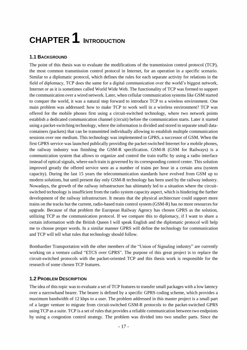
To meet the requirements from the railway industry [1], the GSM technology had to be extended by
several functionalities which are stated in Fig. 2.2 (VGCS, VBS, eMLPP and REC). The Voice Group
Call Service (VGCS) is a group call where only one person can talk at a time. The Voice Broadcast
Service (VBS) is a group call where only the call originator talks and the rest are just listening. The
enhanced MultiLevel Precedence and Pre-emption service (eMLPP) is a service that prioritizes the users
to support the resource reallocation in case of an emergency request. The Railway Emergency Call
(REC) is a high priority form of a VGCS.
- 23 -
Fig. 2.2: GSM-R Components
Another vital difference in relation to the traditional GSM is the band allocation in the radio spectrum
for the GSM-R. Within the territory of EU GSM-R occupies a reserved 4 MHz band (UpLink (UL):
876-880 MHz and DownLink (DL): 921-925 MHz) which fulfills the interoperability requirement. The
system is very robust, i.e. the high level reliability, the availability and the redundancy, due to its serial
structure and closeness to the trackside infrastructure. All those features are maintained with a
guaranteed performance up to 500 km/h. The previously mentioned features comes with the significantly
reduced operational costs compared to the legacy national railway systems, which is a reason why GSM-
R becomes more and more popular even outside EU.
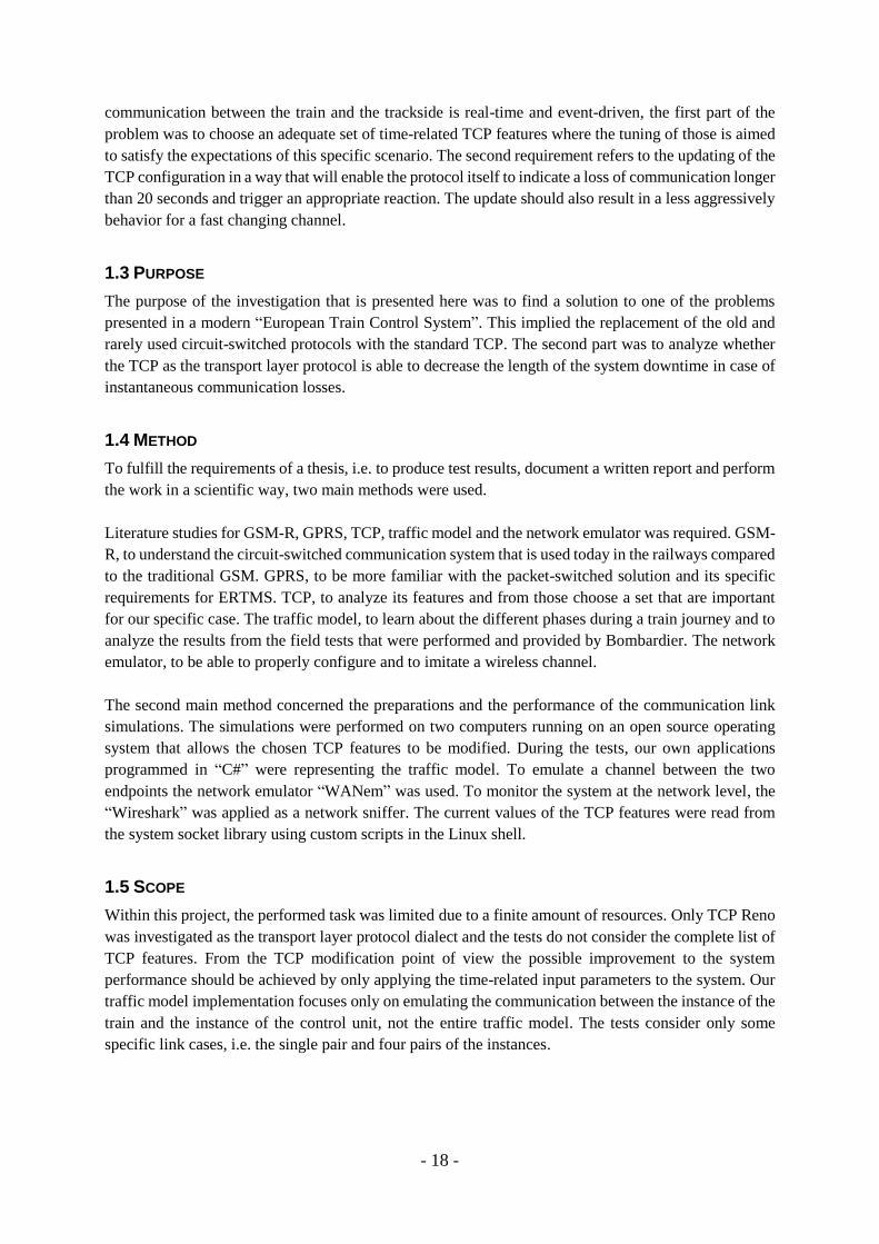
Within the GSM network, the network area is divided into Service Areas (SA), where each SA is
controlled by one MSC (see Fig. 2.3). Each single SA consist a number of smaller regions (Location
Areas (LA)) where each LA covers a group of hexagonal cells. In GSM-R the same structure is used as
in regular GSM, but with the difference that the BSs are placed along the track.
Fig. 2.3: GSM Network Service Areas

- 24 -
2.2.2 GSM DRAWBACKS
GSM is an old mobile communication technology which is evolved into modern solutions (like UMTS
or the more recent LTE) as a response for the new demands from the commercial mobile networks and
its user. These new expectations, e.g. the constantly increased throughput or the better energy efficiency
of the hardware, are not that important for the railway industry as other issues like the service reliability
or the interoperability.
In the railways nowadays the requirements for the data communication dominates over the need of the
voice services, whereas the successors of the traditional GSM in a public sector constantly develop and
support a regular voice communication.
Yet another problematic issue is related to the interference from the public operator’s infrastructure.
Since the commercial sector is constantly channeling its efforts to provide a better coverage, the
development of the GSM-R Base Stations (BS) along the trackside ends up in situations where they
interfere with each other. This problem could be solved by cooperation at the level of the network
planning, i.e. in places where commercial network cells overlap their coverage with the railway network
cells. It would though require a closer dialog, which is not a common practice.
One of the most challenging shortcomings of GSM-R is the limited radio capacity. The 4 MHz
bandwidth is divided into 19 channels, where each channel has the width of 200 kHz and contains a total
number of 8 separate time slots. Within one GSM-R cell only some of those can be used. The reason is
that the neighboring cells cannot reuse the same channels due to co-channel interference.
Furthermore, if we assume that within one channel 7 out of 8 time slots are available for the users with
a fixed throughput, the resources are enough to support the voice traffic. On the other hand, the evolution
of the ERTMS brings up requirements for more capacity that will support the ETCS level-2
communication [2]. This new data-oriented service demands to establish and maintain the continuous
ETCS connection between OBU and RBC for all the trains and each OBU-RBC connection must use at
least one time slot. Previously mentioned issue comes as an effect of the CS-mode, which is substantially
inefficient in this case. The ETCS level-2 and above communication is based on exchanging small
messages in an infrequent manner so a virtual circuit has to be established and maintained between the
endpoints. During the process, when both the endpoints are in an inactive mode, the scarce radio
resources are wasted due to the slot reservation properties, i.e. there is no possibility for sharing of the
virtual circuit with other connections.
GSM-R does not support services such as internet distribution for the passengers etc., which are
becoming more and more required by the customers, i.e. it does not satisfy the requirements for the
throughput and the delay.
2.3 GPRS
As it was previously shown, GSM and its railway optimized version GSM-R have some major
limitations that can restrain the development of heavy public transportation services, e.g. voice
communication, internet distribution etc. This issue was on the scope of a research made by the
European Railway Agency (ERA) for the last few years and meanwhile several different candidate
technologies, like the General Packet Radio Service (GPRS), Universal Mobile Telecommunications
System (UMTS) and Long Term Evolution (LTE) were under an extended investigation. Regardless of
all the advantages and the drawbacks of the two more modern technologies (UMTS and LTE) ERA has
- 25 -
decided to choose GPRS as the solution for the nowadays demands. In this chapter a more detailed
supplementary description is provided.
GPRS should be seen as an extension of GSM that provides a packet-switched service, which works as
a conventional data communication like the internet. Migrating from GSM to GPRS in a nutshell means
moving from the circuit-switched mode to the packet-switched mode, i.e. instead of having an open
connection between the transmitter and the receiver the sent packets contain the sources and the
destinations addresses. GPRS uses the same radio resources (frequencies, modulation schemes, Time
Division Multiple Access (TDMA) frame structure etc.) as GSM but in a more efficient way, e.g. the
frequency band (Packet Data CHannels (PDCH) is shared among the users and each user can use several
time slots when transmitting data. This effect can be seen for instance in the change of the service area
structure.
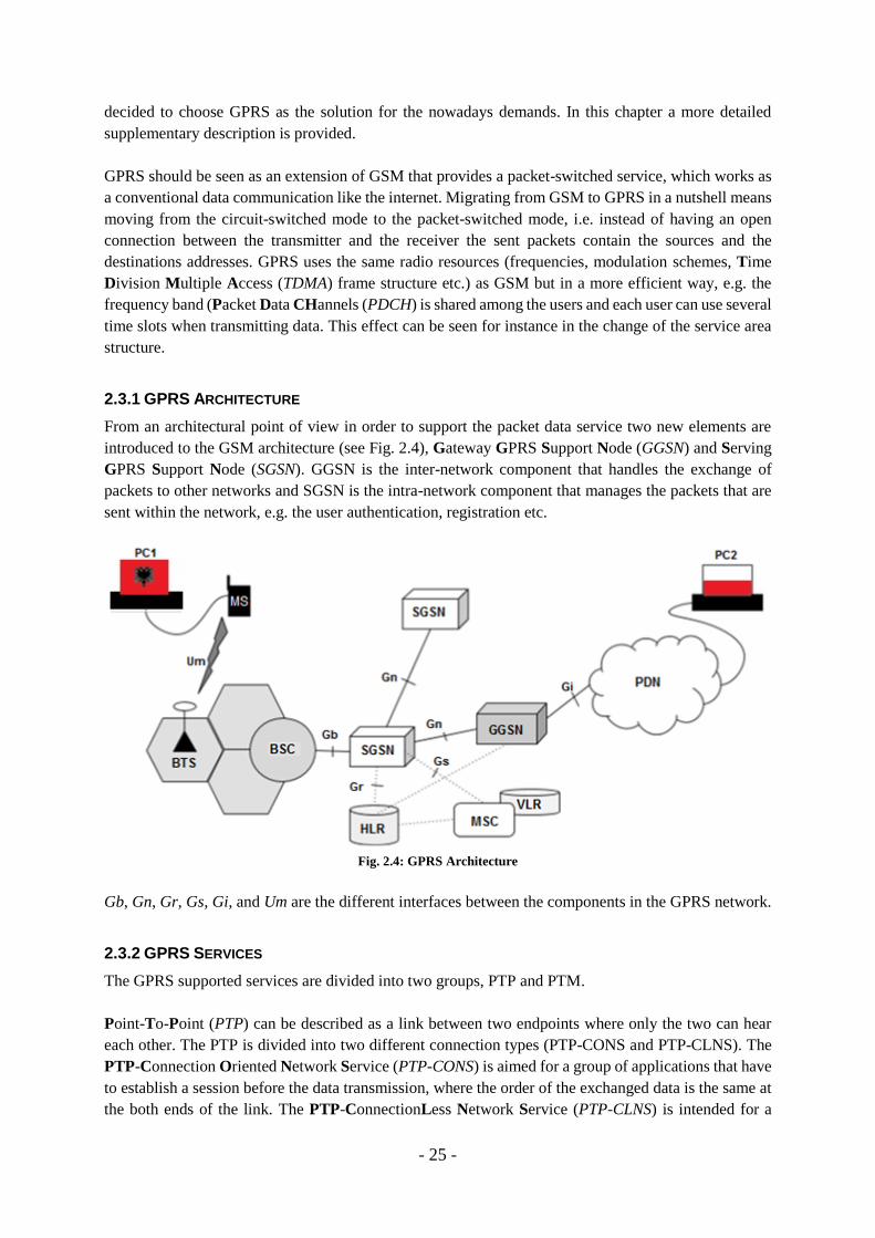
2.3.1 GPRS ARCHITECTURE
From an architectural point of view in order to support the packet data service two new elements are
introduced to the GSM architecture (see Fig. 2.4), Gateway GPRS Support Node (GGSN) and Serving
GPRS Support Node (SGSN). GGSN is the inter-network component that handles the exchange of
packets to other networks and SGSN is the intra-network component that manages the packets that are
sent within the network, e.g. the user authentication, registration etc.
Fig. 2.4: GPRS Architecture
Gb, Gn, Gr, Gs, Gi, and Um are the different interfaces between the components in the GPRS network.
2.3.2 GPRS SERVICES
The GPRS supported services are divided into two groups, PTP and PTM.
Point-To-Point (PTP) can be described as a link between two endpoints where only the two can hear
each other. The PTP is divided into two different connection types (PTP-CONS and PTP-CLNS). The
PTP-Connection Oriented Network Service (PTP-CONS) is aimed for a group of applications that have
to establish a session before the data transmission, where the order of the exchanged data is the same at
the both ends of the link. The PTP-ConnectionLess Network Service (PTP-CLNS) is intended for a

- 26 -
group of applications that allow the packets to be routed separately using various paths so they can be
received in a different time and order.
In Point-To-Multipoint (PTM) one user is distributing messages to several/all receivers in a specific
area. The most common types of the PTM services are split in two components (PTM-M and PTM-G).
The PTM-Multicast (PTM-M) is designed to distribute the message to anonymous receivers in a
scheduled way and is uni-directional. The PTM-Group call (PTM-G) supports applications like
conferences where all the members that have joined the group hear the transmitter. It is in real-time and
the transmission can be uni-, bi- or multi-directional.
2.3.3 GPRS SERVICE AREAS
Previously mentioned services are provided within the range of the SAs, but in GPRS several cells are
gathered into Routeing Areas (RA) instead of LAs. Each SA is controlled by one SGSN and each RA
occupies a relatively smaller space than a LA and can be seen as a part of one LA in the combination of
GSM/GPRS (see Fig. 2.5). When operating on smaller areas the radio resources are easier to optimize,
e.g. the signaling.
Fig. 2.5: GPRS Network Service Areas
2.3.4 GPRS TERMINALS
The terminals in the GPRS systems are divided into three classes (class-A, class-B and class-C) and the
difference between them is the number of simultaneously supported services. In class-A a user is allowed
to transmit and receive voice calls (CS) and data (PS) simultaneously, both the GSM/CS- and GPRS/PS-
connection have equal priority. Class-B is a special case since it allows a user to connect to both GSM
and GPRS but cannot service them simultaneously. It maintains the data transmission during a voice
call, where the voice call has a higher priority. In situations when the packets are under process and a
voice call starts, the data that is processed gets suspended and proceeds when the voice call is finished.
- 27 -
This means that the voice call pre-empts the data transmission. The Class-C terminal provides access to
only one type of the services GSM/GPRS (CS/PS) at any particular time.
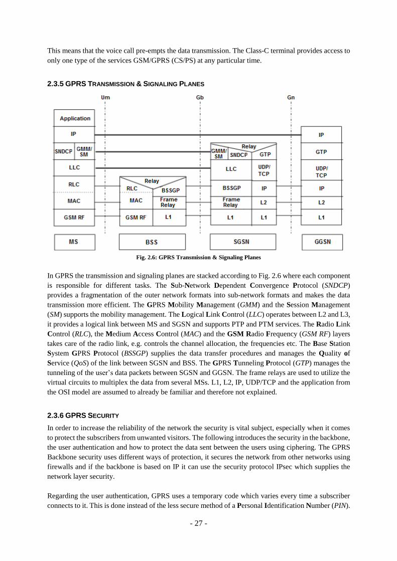
2.3.5 GPRS TRANSMISSION & SIGNALING PLANES
Fig. 2.6: GPRS Transmission & Signaling Planes
In GPRS the transmission and signaling planes are stacked according to Fig. 2.6 where each component
is responsible for different tasks. The Sub-Network Dependent Convergence Protocol (SNDCP)
provides a fragmentation of the outer network formats into sub-network formats and makes the data
transmission more efficient. The GPRS Mobility Management (GMM) and the Session Management
(SM) supports the mobility management. The Logical Link Control (LLC) operates between L2 and L3,
it provides a logical link between MS and SGSN and supports PTP and PTM services. The Radio Link
Control (RLC), the Medium Access Control (MAC) and the GSM Radio Frequency (GSM RF) layers
takes care of the radio link, e.g. controls the channel allocation, the frequencies etc. The Base Station
System GPRS Protocol (BSSGP) supplies the data transfer procedures and manages the Quality of
Service (QoS) of the link between SGSN and BSS. The GPRS Tunneling Protocol (GTP) manages the
tunneling of the user’s data packets between SGSN and GGSN. The frame relays are used to utilize the
virtual circuits to multiplex the data from several MSs. L1, L2, IP, UDP/TCP and the application from
the OSI model are assumed to already be familiar and therefore not explained.
2.3.6 GPRS SECURITY
In order to increase the reliability of the network the security is vital subject, especially when it comes
to protect the subscribers from unwanted visitors. The following introduces the security in the backbone,
the user authentication and how to protect the data sent between the users using ciphering. The GPRS
Backbone security uses different ways of protection, it secures the network from other networks using
firewalls and if the backbone is based on IP it can use the security protocol IPsec which supplies the
network layer security.
Regarding the user authentication, GPRS uses a temporary code which varies every time a subscriber
connects to it. This is done instead of the less secure method of a Personal Identification Number (PIN).
- 28 -
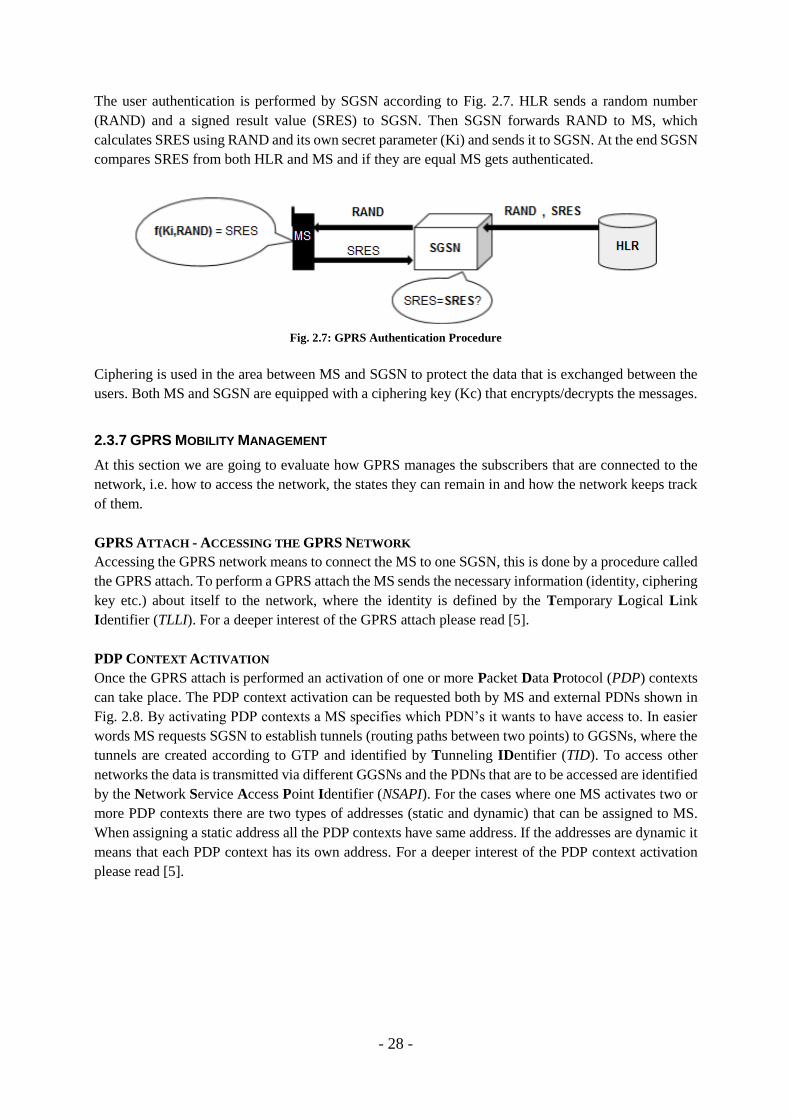
The user authentication is performed by SGSN according to Fig. 2.7. HLR sends a random number
(RAND) and a signed result value (SRES) to SGSN. Then SGSN forwards RAND to MS, which
calculates SRES using RAND and its own secret parameter (Ki) and sends it to SGSN. At the end SGSN
compares SRES from both HLR and MS and if they are equal MS gets authenticated.
Fig. 2.7: GPRS Authentication Procedure
Ciphering is used in the area between MS and SGSN to protect the data that is exchanged between the
users. Both MS and SGSN are equipped with a ciphering key (Kc) that encrypts/decrypts the messages.
2.3.7 GPRS MOBILITY MANAGEMENT
At this section we are going to evaluate how GPRS manages the subscribers that are connected to the
network, i.e. how to access the network, the states they can remain in and how the network keeps track
of them.
GPRS ATTACH - ACCESSING THE GPRS NETWORK
Accessing the GPRS network means to connect the MS to one SGSN, this is done by a procedure called
the GPRS attach. To perform a GPRS attach the MS sends the necessary information (identity, ciphering
key etc.) about itself to the network, where the identity is defined by the Temporary Logical Link
Identifier (TLLI). For a deeper interest of the GPRS attach please read [5].
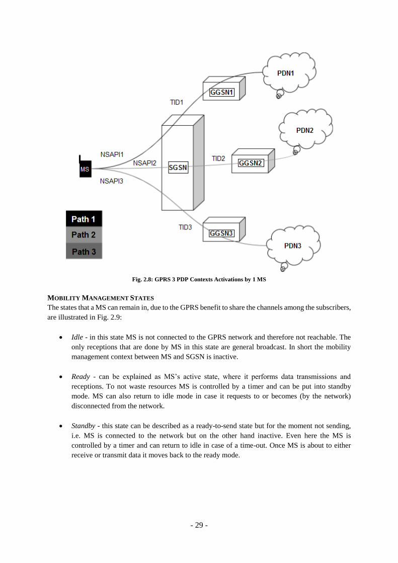
PDP CONTEXT ACTIVATION
Once the GPRS attach is performed an activation of one or more Packet Data Protocol (PDP) contexts
can take place. The PDP context activation can be requested both by MS and external PDNs shown in
Fig. 2.8. By activating PDP contexts a MS specifies which PDN’s it wants to have access to. In easier
words MS requests SGSN to establish tunnels (routing paths between two points) to GGSNs, where the
tunnels are created according to GTP and identified by Tunneling IDentifier (TID). To access other
networks the data is transmitted via different GGSNs and the PDNs that are to be accessed are identified
by the Network Service Access Point Identifier (NSAPI). For the cases where one MS activates two or
more PDP contexts there are two types of addresses (static and dynamic) that can be assigned to MS.
When assigning a static address all the PDP contexts have same address. If the addresses are dynamic it
means that each PDP context has its own address. For a deeper interest of the PDP context activation
please read [5].
- 29 -
Fig. 2.8: GPRS 3 PDP Contexts Activations by 1 MS
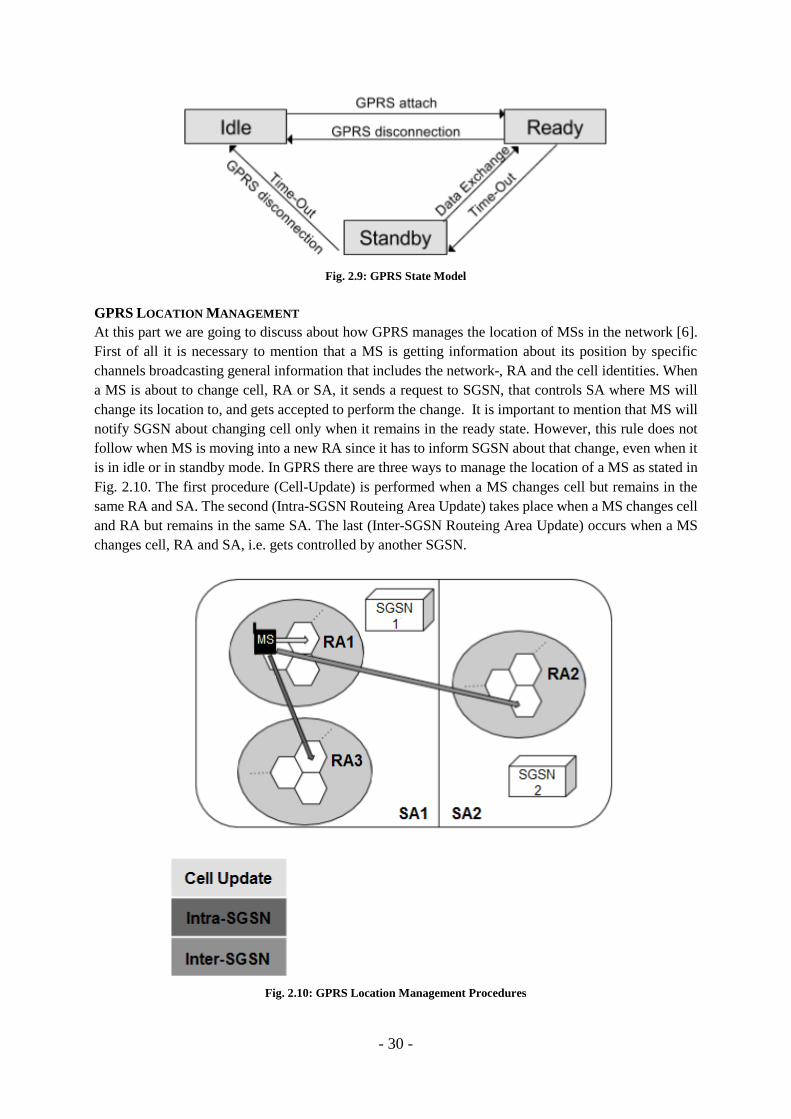
MOBILITY MANAGEMENT STATES
The states that a MS can remain in, due to the GPRS benefit to share the channels among the subscribers,
are illustrated in Fig. 2.9:
Idle - in this state MS is not connected to the GPRS network and therefore not reachable. The
only receptions that are done by MS in this state are general broadcast. In short the mobility
management context between MS and SGSN is inactive.
Ready - can be explained as MS’s active state, where it performs data transmissions and
receptions. To not waste resources MS is controlled by a timer and can be put into standby
mode. MS can also return to idle mode in case it requests to or becomes (by the network)
disconnected from the network.
Standby - this state can be described as a ready-to-send state but for the moment not sending,
i.e. MS is connected to the network but on the other hand inactive. Even here the MS is
controlled by a timer and can return to idle in case of a time-out. Once MS is about to either
receive or transmit data it moves back to the ready mode.
- 30 -
Fig. 2.9: GPRS State Model
GPRS LOCATION MANAGEMENT
At this part we are going to discuss about how GPRS manages the location of MSs in the network [6].
First of all it is necessary to mention that a MS is getting information about its position by specific
channels broadcasting general information that includes the network-, RA and the cell identities. When
a MS is about to change cell, RA or SA, it sends a request to SGSN, that controls SA where MS will
change its location to, and gets accepted to perform the change. It is important to mention that MS will
notify SGSN about changing cell only when it remains in the ready state. However, this rule does not
follow when MS is moving into a new RA since it has to inform SGSN about that change, even when it
is in idle or in standby mode. In GPRS there are three ways to manage the location of a MS as stated in
Fig. 2.10. The first procedure (Cell-Update) is performed when a MS changes cell but remains in the
same RA and SA. The second (Intra-SGSN Routeing Area Update) takes place when a MS changes cell
and RA but remains in the same SA. The last (Inter-SGSN Routeing Area Update) occurs when a MS
changes cell, RA and SA, i.e. gets controlled by another SGSN.
Fig. 2.10: GPRS Location Management Procedures

- 31 -
The location updating procedures are dependent on which state a MS remains in. If MS remains in the
idle state then no updates are performed at all. If MS exists in the standby state no cell updates are
performed, but both the intra-SGSN update and the inter-SGSN update may occur. When MS lasts in
the ready state then SGSN is always informed by MS in case it changes cell, RA or SA, i.e. both the cell
update, the intra-SGSN update and the inter-SGSN update are performed.
SGSN can simply trace if a MS is new in its SA or if it is just changing an RA inside its SA. When a
MS requests an RA-update, it also includes the parameter (old-RA-ID). When SGSN knows the old-
RA-ID of the MS it can easily control if that RA belongs to its SA or not. If the old-RA-ID belongs to
the same SA then an intra-SGSN routeing area update is performed. In case the old-RA-ID belongs to
another SA then an inter-SGSN routeing area update is performed. The procedure starts with that the
MS requests a routeing area update (1 in Fig. 2.11). Then the new SGSN sends a request to the old
SGSN regarding the Mobility Management (MM) and the PDP contexts (2). As a response the old SGSN
provides the new SGSN the MM- and PDP contexts (3). Next, the new SGSN informs GGSN about the
update (4) and at the same time the new SGSN updates the location of MS in HLR (5). When the MS
location is updated HLR requests the old SGSN to remove the MS location data (6) and provides
information about MS to the new SGSN (7). At last the new SGSN accepts the routeing area update (8).
Fig. 2.11: GPRS Inter-SGSN Routeing Area Update
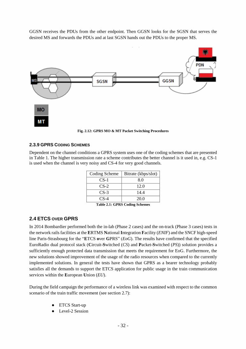
2.3.8 GPRS END-TO-END PACKET ROUTING
After the setup phase where the MS connects to the network, performs the PDP context activations, the
creations of the tunnels take part etc., how is the data transmission performed? There are two ways of
transmitting the data from one point to another illustrated in Fig. 2.12, the mobile originated and the
mobile terminated. Mobile Originated (MO) means that the packets are transmitted from MS to the other
endpoint in another PDN according to the following procedure: First MS sends the PDUs to its serving
SGSN including the destination address. Then SGSN looks for the GGSN that is connected to the desired
PDN and tunnels the PDUs. Lastly GGSN hands out the PDUs to the correct PDN. Mobile Terminated
(MT) is opposite of MO, i.e. MS receives PDUs from another endpoint and follows the procedure: First
- 32 -
GGSN receives the PDUs from the other endpoint. Then GGSN looks for the SGSN that serves the
desired MS and forwards the PDUs and at last SGSN hands out the PDUs to the proper MS.
Fig. 2.12: GPRS MO & MT Packet Switching Procedures
2.3.9 GPRS CODING SCHEMES
Dependent on the channel conditions a GPRS system uses one of the coding schemes that are presented
in Table 1. The higher transmission rate a scheme contributes the better channel is it used in, e.g. CS-1
is used when the channel is very noisy and CS-4 for very good channels.
Coding Scheme Bitrate (kbps/slot)
CS-1 8.0
CS-2 12.0
CS-3 14.4
CS-4 20.0
Table 2.1: GPRS Coding Schemes
2.4 ETCS OVER GPRS
In 2014 Bombardier performed both the in-lab (Phase 2 cases) and the on-track (Phase 3 cases) tests in
the network rails facilities at the ERTMS National Integration Facility (ENIF) and the SNCF high-speed
line Paris-Strasbourg for the “ETCS over GPRS” (EoG). The results have confirmed that the specified
EuroRadio dual protocol stack (Circuit-Switched (CS) and Packet-Switched (PS)) solution provides a
sufficiently enough protected data transmission that meets the requirement for EoG. Furthermore, the
new solutions showed improvement of the usage of the radio resources when compared to the currently
implemented solutions. In general the tests have shown that GPRS as a bearer technology probably
satisfies all the demands to support the ETCS application for public usage in the train communication
services within the European Union (EU).
During the field campaign the performance of a wireless link was examined with respect to the common
scenario of the train traffic movement (see section 2.7):
● ETCS Start-up
● Level-2 Session
- 33 -
● ETCS Termination
Within the above-mentioned phases, the typical train behavior was tested during normal operational
conditions with focus on some special cases such as the “RBC-Handover” and the “Emergency
Message”.
From this project’s point of view the most important results come from the “level-2” scenario which
represents the worst case scenario from the normal train functionality scope. This kind of scenario
corresponds to the situation when the On-Board Unit (OBU) is receiving the new Movement Authority
(MA) from the Radio Block Centre (RBC), which is the heaviest message type used in this
communication system. The conclusions from EoG Phase 2 tests sustain what is already well known
about the GPRS characteristics (low packet loss rate and no packet reordering) from the research done
for the previous generation (2.5G) of the telecommunication standards. Due to this fact the major focus
of interest is directed to the delay. The received averaged value of the Round Trip Delay (RTD) for the
MA message was 0.78 s and for 95% of all the cases it turned out to be <1 s for a single OBU-RBC link
using the PS-mode, which represents the typical transmission delay. Furthermore, according to the
results from the lab simulations in Phase 2, the MA updating time, i.e. the longest time a train can
continue its travel without any changes like speed, shall not exceed 12 s in 99.99% of the cases.
Another valid result comes from the tests of the RBC-RBC-Handover scenario, where the goal was to
compare the time needed to perform the packet-switched mode transmissions during a cell reselection.
The average measured value turned out to be 1.16 s (the mobile terminal of OBU was GPRS attached
and the PDP context was activated). The result from this test case is important because it represents the
event that occurs frequently during the train travel and has a more periodic characteristic than a random
and instantaneous degradation of the radio channel.
According to the report, the weather conditions during the field test were good (clear sky with no
interference from atmospheric phenomena). All relevant tests were performed in communication
between the single pair of OBU-RBC equipment (test track limitations) [7].
2.5 TCP
2.5.1 CORE FUNCTIONALITY
TCP is the standard nowadays, i.e. the most popular transmission protocol that is used to exchange
information in form of fragmented portions of the data and is widely supported by different operating
systems. The TCP is reliable thanks to several mechanisms that control the state of the
telecommunication link, the packet degradation and the reorganization.
In the old data networks when TCP was implemented for the first time the Quality of Service (QoS) was
usually affected by sudden changes in the offered load and this caused network congestions. Network
congestion can be explained as the effect of the queuing delay, a connection blocking or a packet loss.
In this situation the sender is not receiving the expected ACKnowledgements (ACK) for the sent data
and usually reacts by sending retransmissions. If the throughput decrease was not caused by a temporary
incident the system remains in the state when the demand traffic is much higher than the available useful
throughput. The problem stacks and leads to the congestion collapse state. This was the common
- 34 -
scenario for the very early TCP implementations and it was the first evidence of the fact that the
retransmission mechanism was not enough to efficiently maintain data links.
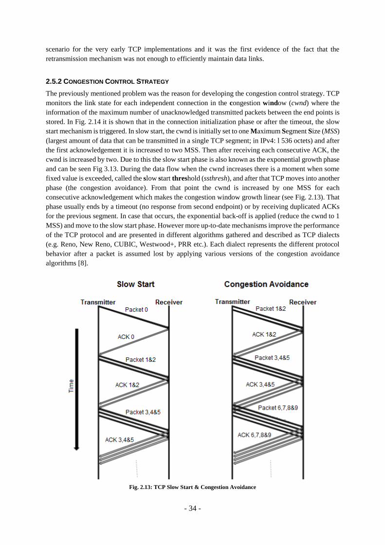
2.5.2 CONGESTION CONTROL STRATEGY
The previously mentioned problem was the reason for developing the congestion control strategy. TCP
monitors the link state for each independent connection in the congestion window (cwnd) where the
information of the maximum number of unacknowledged transmitted packets between the end points is
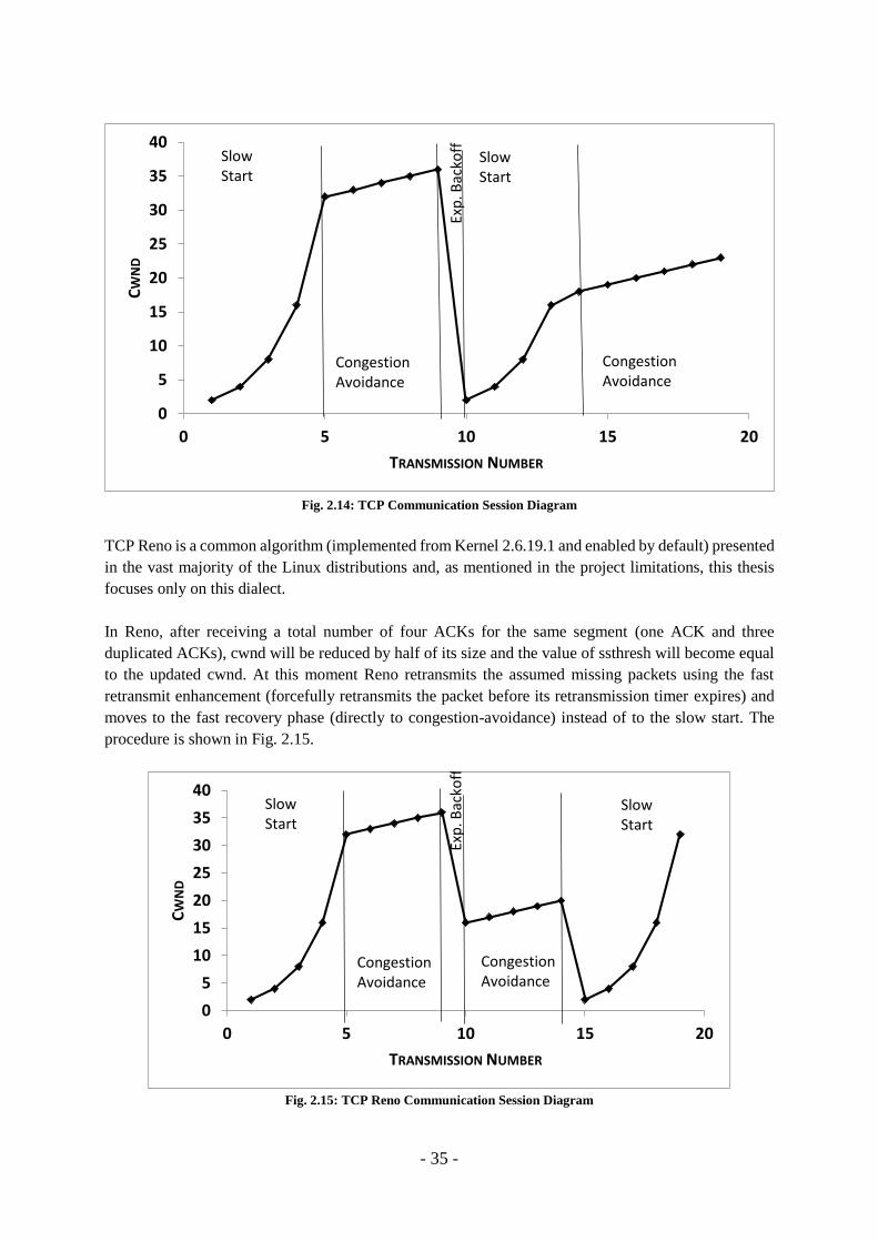
stored. In Fig. 2.14 it is shown that in the connection initialization phase or after the timeout, the slow
start mechanism is triggered. In slow start, the cwnd is initially set to one Maximum Segment Size (MSS)
(largest amount of data that can be transmitted in a single TCP segment; in IPv4: l 536 octets) and after
the first acknowledgement it is increased to two MSS. Then after receiving each consecutive ACK, the
cwnd is increased by two. Due to this the slow start phase is also known as the exponential growth phase
and can be seen Fig 3.13. During the data flow when the cwnd increases there is a moment when some
fixed value is exceeded, called the slow start threshold (ssthresh), and after that TCP moves into another
phase (the congestion avoidance). From that point the cwnd is increased by one MSS for each
consecutive acknowledgement which makes the congestion window growth linear (see Fig. 2.13). That
phase usually ends by a timeout (no response from second endpoint) or by receiving duplicated ACKs
for the previous segment. In case that occurs, the exponential back-off is applied (reduce the cwnd to 1
MSS) and move to the slow start phase. However more up-to-date mechanisms improve the performance
of the TCP protocol and are presented in different algorithms gathered and described as TCP dialects
(e.g. Reno, New Reno, CUBIC, Westwood+, PRR etc.). Each dialect represents the different protocol
behavior after a packet is assumed lost by applying various versions of the congestion avoidance
algorithms [8].
Fig. 2.13: TCP Slow Start & Congestion Avoidance
- 35 -
Fig. 2.14: TCP Communication Session Diagram
TCP Reno is a common algorithm (implemented from Kernel 2.6.19.1 and enabled by default) presented
in the vast majority of the Linux distributions and, as mentioned in the project limitations, this thesis
focuses only on this dialect.
In Reno, after receiving a total number of four ACKs for the same segment (one ACK and three
duplicated ACKs), cwnd will be reduced by half of its size and the value of ssthresh will become equal
to the updated cwnd. At this moment Reno retransmits the assumed missing packets using the fast
retransmit enhancement (forcefully retransmits the packet before its retransmission timer expires) and
moves to the fast recovery phase (directly to congestion-avoidance) instead of to the slow start. The
procedure is shown in Fig. 2.15.
Fig. 2.15: TCP Reno Communication Session Diagram
0
5
10
15
20
25
30
35
40
0 5 10 15 20
CW
ND
TRANSMISSION NUMBER
SlowStart
Congestion Avoidance
Exp
.Bac
koff
SlowStart
CongestionAvoidance
0
5
10
15
20
25
30
35
40
0 5 10 15 20
CW
ND
TRANSMISSION NUMBER
SlowStart
SlowStart
CongestionAvoidance
CongestionAvoidance
Exp
. Bac
koff
- 36 -
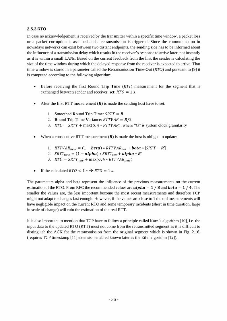
2.5.3 RTO
In case no acknowledgement is received by the transmitter within a specific time window, a packet loss
or a packet corruption is assumed and a retransmission is triggered. Since the communication in
nowadays networks can exist between two distant endpoints, the sending side has to be informed about
the influence of a transmission delay which results in the receiver’s response to arrive later, not instantly
as it is within a small LANs. Based on the current feedback from the link the sender is calculating the
size of the time window during which the delayed response from the receiver is expected to arrive. That
time window is stored in a parameter called the Retransmission Time-Out (RTO) and pursuant to [9] it
is computed according to the following algorithm:
Before receiving the first Round Trip Time (RTT) measurement for the segment that is
exchanged between sender and receiver, set: 𝑅𝑇𝑂 = 1 𝑠.
After the first RTT measurement (𝑹) is made the sending host have to set:
1. Smoothed Round Trip Time: 𝑆𝑅𝑇𝑇 = 𝑹
2. Round Trip Time Variance: 𝑅𝑇𝑇𝑉𝐴𝑅 = 𝑹/2
3. 𝑅𝑇𝑂 = 𝑆𝑅𝑇𝑇 + max (𝐺, 4 ∗ 𝑅𝑇𝑇𝑉𝐴𝑅), where “G” is system clock granularity
When a consecutive RTT measurement (𝑹) is made the host is obliged to update:
1. 𝑅𝑇𝑇𝑉𝐴𝑅𝑛𝑒𝑤 = (1 − 𝒃𝒆𝒕𝒂) ∗ 𝑅𝑇𝑇𝑉𝐴𝑅𝑜𝑙𝑑 + 𝒃𝒆𝒕𝒂 ∗ |𝑆𝑅𝑇𝑇 − 𝑹′|
2. 𝑆𝑅𝑇𝑇𝑛𝑒𝑤 = (1 − 𝒂𝒍𝒑𝒉𝒂) ∗ 𝑆𝑅𝑇𝑇𝑜𝑙𝑑 + 𝒂𝒍𝒑𝒉𝒂 ∗ 𝑹′
3. 𝑅𝑇𝑂 = 𝑆𝑅𝑇𝑇𝑛𝑒𝑤 + max (𝐺, 4 ∗ 𝑅𝑇𝑇𝑉𝐴𝑅𝑛𝑒𝑤)
If the calculated 𝑅𝑇𝑂 < 1 𝑠 𝑅𝑇𝑂 = 1 𝑠.
The parameters alpha and beta represent the influence of the previous measurements on the current
estimation of the RTO. From RFC the recommended values are 𝒂𝒍𝒑𝒉𝒂 = 𝟏 ⁄ 𝟖 and 𝒃𝒆𝒕𝒂 = 𝟏 ⁄ 𝟒. The
smaller the values are, the less important become the most recent measurements and therefore TCP
might not adapt to changes fast enough. However, if the values are close to 1 the old measurements will
have negligible impact on the current RTO and some temporary incidents (short in time duration, large
in scale of change) will ruin the estimation of the real RTT.
It is also important to mention that TCP have to follow a principle called Karn’s algorithm [10], i.e. the
input data to the updated RTO (RTT) must not come from the retransmitted segment as it is difficult to
distinguish the ACK for the retransmission from the original segment which is shown in Fig. 2.16.
(requires TCP timestamp [11] extension enabled known later as the Eifel algorithm [12]).

- 37 -
Fig. 2.16: Karn’s Algorithm
2.5.4 TCP_RTO_MIN
Despite the fact, according to RFC the final RTO value could not be set below 1 s, several operating
systems have implemented much smaller values for the lower bound of the retransmission timeout stated
in Fig. 2.17 [13]. The motivation behind that change comes from the fact, that in modern systems,
especially in data centers and Storage Area Networks (SANs), RTT of the packets is usually far below
the 1 s due to extremely higher link throughputs compared to the performance of the links from the time
of the TCP RTO appearance. In addition, even over Wide Area Networks (WAN) we usually reach RTT
below the value suggested by RFC and the transmission delay will be improved even more as we still
modernize the telecommunication links.
Scenario OS RTT (ms) RTOmin (ms)
WAN Linux ~ 100 ~ 200
Datacenter BSD ~ 1 ~ 200
SAN Solaris ~ 0.1 ~ 400 Fig. 2.17: RTT in Systems over Different Scenarios [13]
TCP_RTO_MIN is a static parameter that defines the lower bound of RTO, i.e. even though RTO adapts
to the changing RTT according to TCP it can never drop below a specific minimum value. Its magnitude
is usually hard-coded in the OS kernel along with other TCP regular instructions. It protects TCP from
unwanted unnecessarily long time-outs triggered by e.g. delayed acknowledgements, packet losses etc.
According to RFC 1122 the default TCP_RTO_MIN value should be measured in fractions of a second
(to accommodate high speed LANs).
Since the transmission channel affects RTT and in turn RTO, TCP_RTO_MIN is related to the channel
performance. The better channel the faster the acknowledgements from the receiver arrive which in turn
means that TCP_RTO_MIN must be set to a low value. In case of noisy channels, e.g. wireless traffic
in the train-trackside communication, where the RTTs and their equivalent RTOs are expected to be
higher, it is recommended to tune TCP_RTO_MIN to a higher value. For the case of this project a
suitable value is 2 s, since for a single OBU-RBC link the transmission delay <1 s, i.e. in two directions
the total RTTs becomes less than 2 s [14].

- 38 -
2.5.5 TCP_KEEPALIVE
TCP_KEEPALIVE is another TCP feature that allows monitoring the status of the existence of the
second transmission endpoint. The purpose of TCP_KEEPALIVE is to keep the TCP session alive for
a certain amount of time even though no data is exchanged. Within the OS implementation we can
distinguish three variables that control this feature:
TCP_KEEPALIVE_TIME: defines the time window in seconds that the socket has to wait until
starting to send the first probe when there is no transmission.
TCP_KEEPALIVE_PROBES: defines the number of probes that are sent to investigate whether
the other side is in idle or terminated.
TCP_KEEPALIVE_INTVL: defines the interval in seconds between the probes.
A typical scenario for TCP_KEEPALIVE is shown in Fig. 2.18, where PC1 is communicating with PC2
and then suddenly PC2 stops receiving packets (no FIN flag present) and waits for an amount of time
(specified by TCP_KEEPALIVE_TIME) until it starts to react. If PC2 still does not receive anything
after this amount of time, then PC2 sends the first probe to PC1 to investigate whether PC1 is just in
idle mode or if the link is down. If PC1 does not respond after an amount of time (specified by
TCP_KEEPALIVE_INTVL), then PC2 sends the second probe and continues until it send the last probe
(specified by TCP_KEEPALIVE_PROBES). When the last probe is sent and PC1 still does not respond,
then after the last probe interval PC2 terminates the connection.
Fig. 2.18: TCP_KEEPALIVE Scenario
TCP_KEEPALIVE is implemented by default as one of the TCP features. The initial values for our
chosen Linux distribution were TIME = 7200 s, PROBES = 9 and INTVL = 75 s. However, a specific
application wants to take advantage of using this feature has to request it. This is achieved by enabling
TCP_KEEPALIVE option in the system socket instructions within the application code.
- 39 -
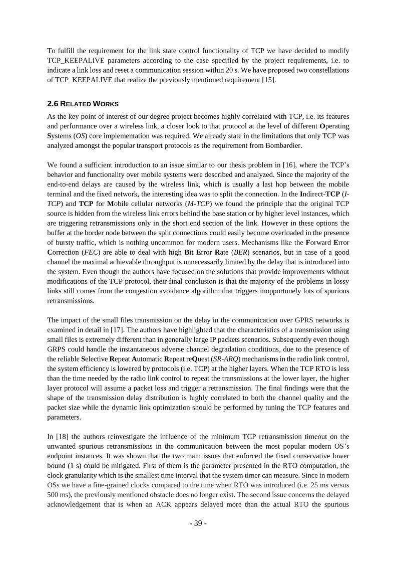
To fulfill the requirement for the link state control functionality of TCP we have decided to modify
TCP_KEEPALIVE parameters according to the case specified by the project requirements, i.e. to
indicate a link loss and reset a communication session within 20 s. We have proposed two constellations
of TCP_KEEPALIVE that realize the previously mentioned requirement [15].
2.6 RELATED WORKS
As the key point of interest of our degree project becomes highly correlated with TCP, i.e. its features
and performance over a wireless link, a closer look to that protocol at the level of different Operating
Systems (OS) core implementation was required. We already state in the limitations that only TCP was
analyzed amongst the popular transport protocols as the requirement from Bombardier.
We found a sufficient introduction to an issue similar to our thesis problem in [16], where the TCP’s
behavior and functionality over mobile systems were described and analyzed. Since the majority of the
end-to-end delays are caused by the wireless link, which is usually a last hop between the mobile
terminal and the fixed network, the interesting idea was to split the connection. In the Indirect-TCP (I-
TCP) and TCP for Mobile cellular networks (M-TCP) we found the principle that the original TCP
source is hidden from the wireless link errors behind the base station or by higher level instances, which
are triggering retransmissions only in the short end section of the link. However in these options the
buffer at the border node between the split connections could easily become overloaded in the presence
of bursty traffic, which is nothing uncommon for modern users. Mechanisms like the Forward Error
Correction (FEC) are able to deal with high Bit Error Rate (BER) scenarios, but in case of a good
channel the maximal achievable throughput is unnecessarily limited by the delay that is introduced into
the system. Even though the authors have focused on the solutions that provide improvements without
modifications of the TCP protocol, their final conclusion is that the majority of the problems in lossy
links still comes from the congestion avoidance algorithm that triggers inopportunely lots of spurious
retransmissions.
The impact of the small files transmission on the delay in the communication over GPRS networks is
examined in detail in [17]. The authors have highlighted that the characteristics of a transmission using
small files is extremely different than in generally large IP packets scenarios. Subsequently even though
GRPS could handle the instantaneous adverse channel degradation conditions, due to the presence of
the reliable Selective Repeat Automatic Repeat reQuest (SR-ARQ) mechanisms in the radio link control,
the system efficiency is lowered by protocols (i.e. TCP) at the higher layers. When the TCP RTO is less
than the time needed by the radio link control to repeat the transmissions at the lower layer, the higher
layer protocol will assume a packet loss and trigger a retransmission. The final findings were that the
shape of the transmission delay distribution is highly correlated to both the channel quality and the
packet size while the dynamic link optimization should be performed by tuning the TCP features and
parameters.
In [18] the authors reinvestigate the influence of the minimum TCP retransmission timeout on the
unwanted spurious retransmissions in the communication between the most popular modern OS’s
endpoint instances. It was shown that the two main issues that enforced the fixed conservative lower
bound (1 s) could be mitigated. First of them is the parameter presented in the RTO computation, the
clock granularity which is the smallest time interval that the system timer can measure. Since in modern
OSs we have a fine-grained clocks compared to the time when RTO was introduced (i.e. 25 ms versus
500 ms), the previously mentioned obstacle does no longer exist. The second issue concerns the delayed
acknowledgement that is when an ACK appears delayed more than the actual RTO the spurious
- 40 -
retransmission is triggered. To mitigate that problem a new mechanism was introduced, in which the
host is notified about a possible longer delay for an ACK. The update was evaluated in the tests over the
network simulator. The conclusion was that the TCP performance is possible to improve in the next
generation wireless-access networks, operating on high-speeds and in the presence of content-rich data
streams (100 kBs) and the motivation for a secure and 1 s lower bound is obsolete. However, the
simulations did not cover the scenarios, where very short streams of data (i.e., 25-500 kBs) are
infrequently used over narrow bandwidth links.
The impact of the RTO timer settings alpha and beta on the system performance of a bare PC Web server
operating without neither an OS nor the kernel was analyzed in [19]. During the tests different setups of
the alpha and beta values under the influence of different levels of the background traffic were examined.
The investigation contained also the test cases, where the lower than the recommended minimum RTO
was presented. The results have shown that there is no best combination of alpha and beta for the various
levels of the background cases. Only in a few specific scenarios the lower RTO minimum parameter
was more efficient than the recommended value.
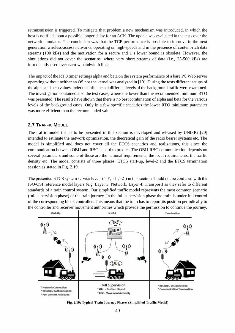
2.7 TRAFFIC MODEL
The traffic model that is to be presented in this section is developed and released by UNISIG [20]
intended to estimate the network optimization, the theoretical gain of the radio bearer systems etc. The
model is simplified and does not cover all the ETCS scenarios and realizations, this since the
communication between OBU and RBC is hard to predict. The OBU-RBC communication depends on
several parameters and some of those are the national requirements, the local requirements, the traffic
density etc. The model consists of three phases: ETCS start-up, level-2 and the ETCS termination
session as stated in Fig. 2.19.
The presented ETCS system service levels (‘-0’,’-1’,’-2’) in this section should not be confused with the
ISO/OSI reference model layers (e.g. Layer 3: Network, Layer 4: Transport) as they refer to different
standards of a train control system. Our simplified traffic model represents the most common scenario
(full supervision phase) of the train journey. In the full supervision phase the train is under full control
of the corresponding block controller. This means that the train has to report its position periodically to
the controller and receiver movement authorities which provide the permission to continue the journey.
Fig. 2.19: Typical Train Journey Phases (Simplified Traffic Model)
- 41 -
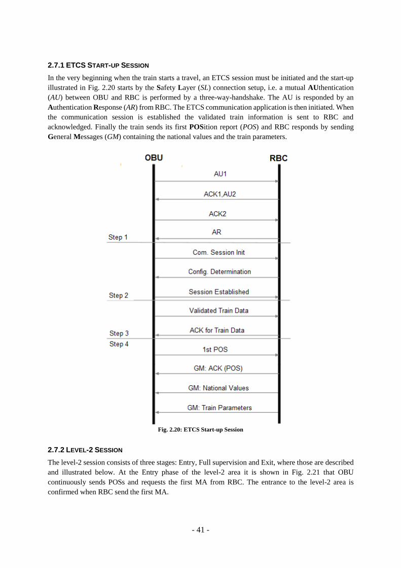
2.7.1 ETCS START-UP SESSION
In the very beginning when the train starts a travel, an ETCS session must be initiated and the start-up
illustrated in Fig. 2.20 starts by the Safety Layer (SL) connection setup, i.e. a mutual AUthentication
(AU) between OBU and RBC is performed by a three-way-handshake. The AU is responded by an
Authentication Response (AR) from RBC. The ETCS communication application is then initiated. When
the communication session is established the validated train information is sent to RBC and
acknowledged. Finally the train sends its first POSition report (POS) and RBC responds by sending
General Messages (GM) containing the national values and the train parameters.
Fig. 2.20: ETCS Start-up Session
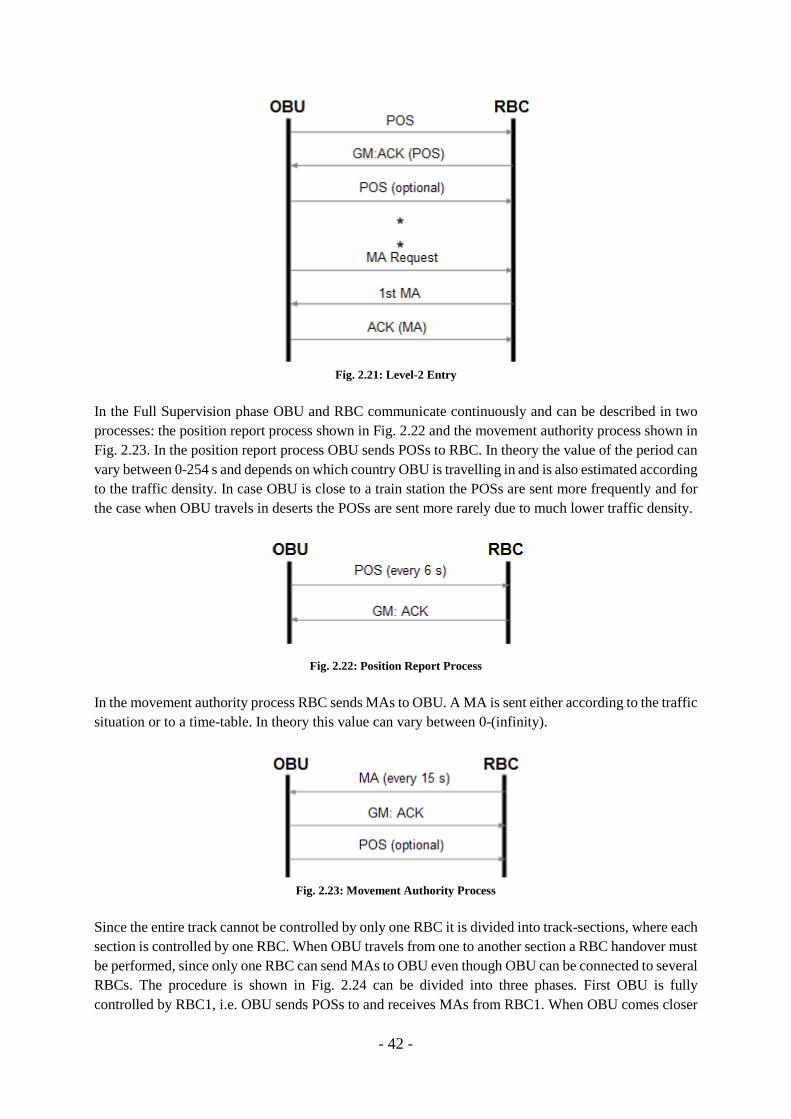
2.7.2 LEVEL-2 SESSION
The level-2 session consists of three stages: Entry, Full supervision and Exit, where those are described
and illustrated below. At the Entry phase of the level-2 area it is shown in Fig. 2.21 that OBU
continuously sends POSs and requests the first MA from RBC. The entrance to the level-2 area is
confirmed when RBC send the first MA.
- 42 -
Fig. 2.21: Level-2 Entry
In the Full Supervision phase OBU and RBC communicate continuously and can be described in two
processes: the position report process shown in Fig. 2.22 and the movement authority process shown in
Fig. 2.23. In the position report process OBU sends POSs to RBC. In theory the value of the period can
vary between 0-254 s and depends on which country OBU is travelling in and is also estimated according
to the traffic density. In case OBU is close to a train station the POSs are sent more frequently and for
the case when OBU travels in deserts the POSs are sent more rarely due to much lower traffic density.
Fig. 2.22: Position Report Process
In the movement authority process RBC sends MAs to OBU. A MA is sent either according to the traffic
situation or to a time-table. In theory this value can vary between 0-(infinity).
Fig. 2.23: Movement Authority Process
Since the entire track cannot be controlled by only one RBC it is divided into track-sections, where each
section is controlled by one RBC. When OBU travels from one to another section a RBC handover must
be performed, since only one RBC can send MAs to OBU even though OBU can be connected to several
RBCs. The procedure is shown in Fig. 2.24 can be divided into three phases. First OBU is fully
controlled by RBC1, i.e. OBU sends POSs to and receives MAs from RBC1. When OBU comes closer
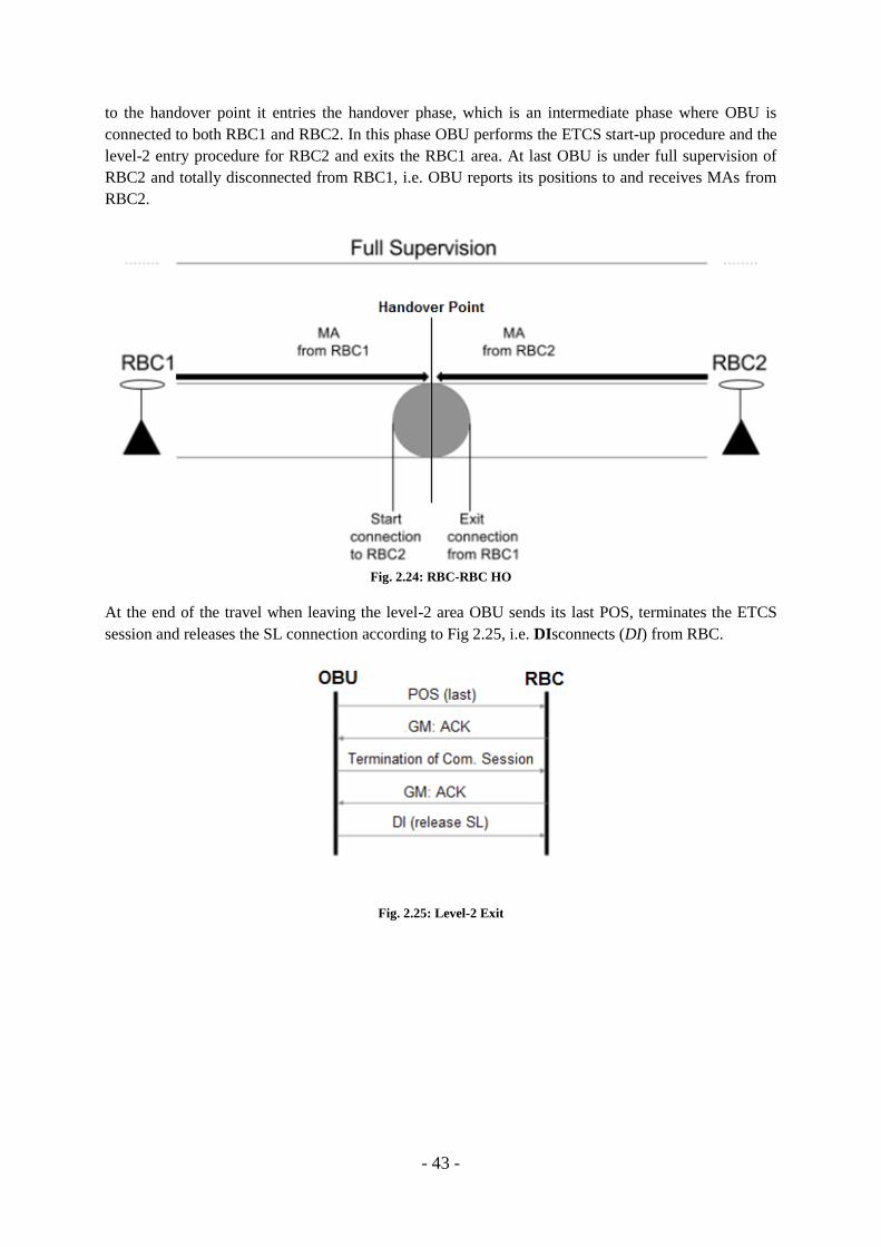
- 43 -
to the handover point it entries the handover phase, which is an intermediate phase where OBU is
connected to both RBC1 and RBC2. In this phase OBU performs the ETCS start-up procedure and the
level-2 entry procedure for RBC2 and exits the RBC1 area. At last OBU is under full supervision of
RBC2 and totally disconnected from RBC1, i.e. OBU reports its positions to and receives MAs from
RBC2.
Fig. 2.24: RBC-RBC HO
At the end of the travel when leaving the level-2 area OBU sends its last POS, terminates the ETCS
session and releases the SL connection according to Fig 2.25, i.e. DIsconnects (DI) from RBC.
Fig. 2.25: Level-2 Exit

- 44 -

- 45 -
CHAPTER 3 SYSTEM DESCRIPTION
3.1 TEST APPLICATIONS
For the realization of the previous mentioned simplified traffic model two custom applications have
been developed. These applications operate in a client-server mode and were designed to imitate the
OBU-RBC communication link, where RBC is the server and OBU is the client. In our model POSs are
sent periodically (every 6 s) and MAs are sent every 15 s. It is important to remind that the number of
the covered scenarios is limited to the full-supervision phase only since it is the most common case. Our
custom applications have been design to work in the following way:
1. RBC application, launched as a first in order, is listening for the connection requests from OBU.
2. OBU application, when executed, tries to connect to RBC.
3. When the RBC-OBU session is successfully established both the applications are exchanging
the proper messages:
i. RBC starts to send MAs repeatedly after each 15 s with the first message sent
immediately when the connection is established.
ii. At the same time OBU starts to send POSs repeatedly after each 6 s with the first
message sent immediately when the connection is established.
iii. Both RBC and OBU are sending ACKs when a consecutive message is received. In this
moment it is important to highlight that the mentioned ACKs are a separate type of
messages possible to detect in the console and are not the acknowledgements used by
the transmission control protocol.
iv. The RBC application contains the enabled TCP_KEEPALIVE feature that will indicate
a communication loss and reset the connection in case of the inactivity of the other
endpoint, since RBC is the server and is not directly connected to the wireless network.
3.2 TESTBED
The testbed was built up by three active components stated in Table 3.1 and illustrated in Fig. 3.1: PC#1
running the network emulator, PC#2 running the OBU application and PC#3 running the RBC
application. In the testbed the internet access was required, since there was a need of a Domain Name
System (DNS) server when a connection was about to be established between RBC and OBU. This
requirement was added to provide an extension for future studies with possible internet access to the
OBU/RBC.
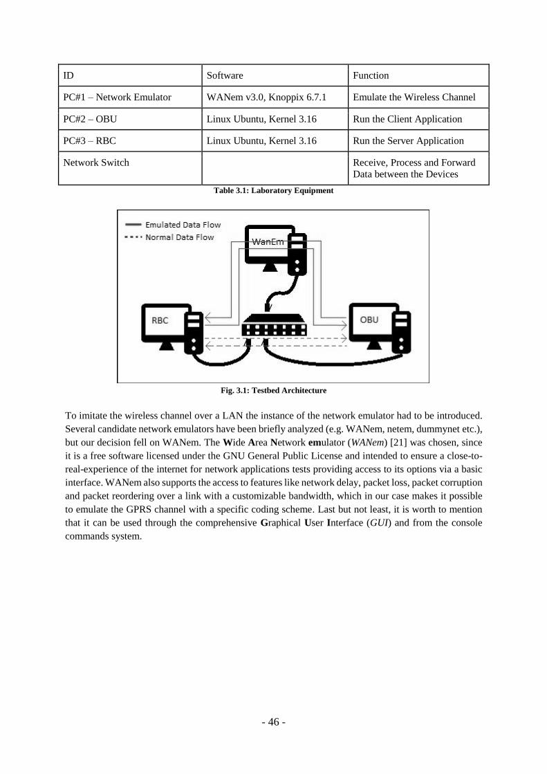
- 46 -
ID Software Function
PC#1 – Network Emulator WANem v3.0, Knoppix 6.7.1 Emulate the Wireless Channel
PC#2 – OBU Linux Ubuntu, Kernel 3.16 Run the Client Application
PC#3 – RBC Linux Ubuntu, Kernel 3.16 Run the Server Application
Network Switch Receive, Process and Forward
Data between the Devices
Table 3.1: Laboratory Equipment
Fig. 3.1: Testbed Architecture
To imitate the wireless channel over a LAN the instance of the network emulator had to be introduced.
Several candidate network emulators have been briefly analyzed (e.g. WANem, netem, dummynet etc.),
but our decision fell on WANem. The Wide Area Network emulator (WANem) [21] was chosen, since
it is a free software licensed under the GNU General Public License and intended to ensure a close-to-
real-experience of the internet for network applications tests providing access to its options via a basic
interface. WANem also supports the access to features like network delay, packet loss, packet corruption
and packet reordering over a link with a customizable bandwidth, which in our case makes it possible
to emulate the GPRS channel with a specific coding scheme. Last but not least, it is worth to mention
that it can be used through the comprehensive Graphical User Interface (GUI) and from the console
commands system.
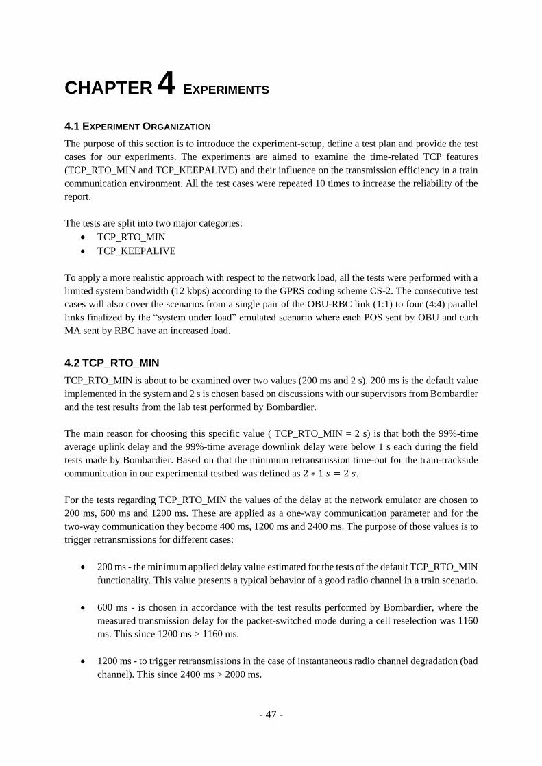
- 47 -
CHAPTER 4 EXPERIMENTS
4.1 EXPERIMENT ORGANIZATION
The purpose of this section is to introduce the experiment-setup, define a test plan and provide the test
cases for our experiments. The experiments are aimed to examine the time-related TCP features
(TCP_RTO_MIN and TCP_KEEPALIVE) and their influence on the transmission efficiency in a train
communication environment. All the test cases were repeated 10 times to increase the reliability of the
report.
The tests are split into two major categories:
TCP_RTO_MIN
TCP_KEEPALIVE
To apply a more realistic approach with respect to the network load, all the tests were performed with a
limited system bandwidth (12 kbps) according to the GPRS coding scheme CS-2. The consecutive test
cases will also cover the scenarios from a single pair of the OBU-RBC link (1:1) to four (4:4) parallel
links finalized by the “system under load” emulated scenario where each POS sent by OBU and each
MA sent by RBC have an increased load.
4.2 TCP_RTO_MIN
TCP_RTO_MIN is about to be examined over two values (200 ms and 2 s). 200 ms is the default value
implemented in the system and 2 s is chosen based on discussions with our supervisors from Bombardier
and the test results from the lab test performed by Bombardier.
The main reason for choosing this specific value ( TCP_RTO_MIN = 2 s) is that both the 99%-time
average uplink delay and the 99%-time average downlink delay were below 1 s each during the field
tests made by Bombardier. Based on that the minimum retransmission time-out for the train-trackside
communication in our experimental testbed was defined as 2 ∗ 1 𝑠 = 2 𝑠.
For the tests regarding TCP_RTO_MIN the values of the delay at the network emulator are chosen to
200 ms, 600 ms and 1200 ms. These are applied as a one-way communication parameter and for the
two-way communication they become 400 ms, 1200 ms and 2400 ms. The purpose of those values is to
trigger retransmissions for different cases:
200 ms - the minimum applied delay value estimated for the tests of the default TCP_RTO_MIN
functionality. This value presents a typical behavior of a good radio channel in a train scenario.
600 ms - is chosen in accordance with the test results performed by Bombardier, where the
measured transmission delay for the packet-switched mode during a cell reselection was 1160
ms. This since 1200 ms > 1160 ms.
1200 ms - to trigger retransmissions in the case of instantaneous radio channel degradation (bad
channel). This since 2400 ms > 2000 ms.
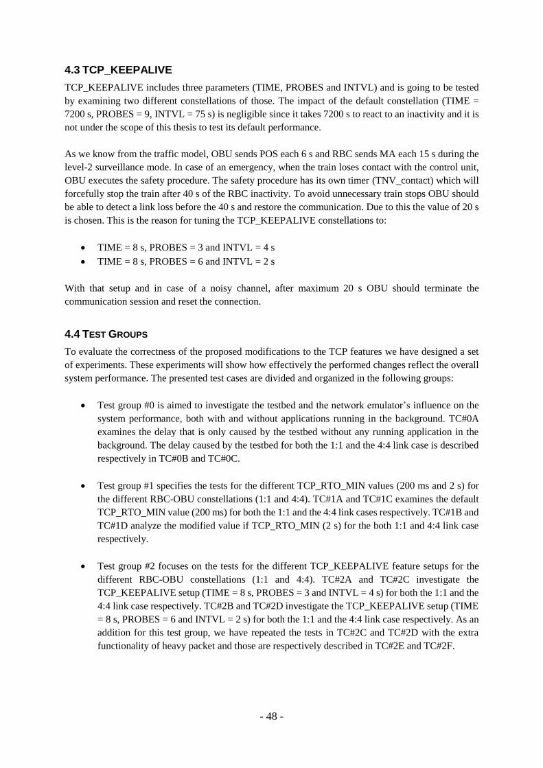
- 48 -
4.3 TCP_KEEPALIVE
TCP_KEEPALIVE includes three parameters (TIME, PROBES and INTVL) and is going to be tested
by examining two different constellations of those. The impact of the default constellation (TIME =
7200 s, PROBES = 9, INTVL = 75 s) is negligible since it takes 7200 s to react to an inactivity and it is
not under the scope of this thesis to test its default performance.
As we know from the traffic model, OBU sends POS each 6 s and RBC sends MA each 15 s during the
level-2 surveillance mode. In case of an emergency, when the train loses contact with the control unit,
OBU executes the safety procedure. The safety procedure has its own timer (TNV_contact) which will
forcefully stop the train after 40 s of the RBC inactivity. To avoid unnecessary train stops OBU should
be able to detect a link loss before the 40 s and restore the communication. Due to this the value of 20 s
is chosen. This is the reason for tuning the TCP_KEEPALIVE constellations to:
TIME = 8 s, PROBES = 3 and INTVL = 4 s
TIME = 8 s, PROBES = 6 and INTVL = 2 s
With that setup and in case of a noisy channel, after maximum 20 s OBU should terminate the
communication session and reset the connection.
4.4 TEST GROUPS
To evaluate the correctness of the proposed modifications to the TCP features we have designed a set
of experiments. These experiments will show how effectively the performed changes reflect the overall
system performance. The presented test cases are divided and organized in the following groups:
Test group #0 is aimed to investigate the testbed and the network emulator’s influence on the
system performance, both with and without applications running in the background. TC#0A
examines the delay that is only caused by the testbed without any running application in the
background. The delay caused by the testbed for both the 1:1 and the 4:4 link case is described
respectively in TC#0B and TC#0C.
Test group #1 specifies the tests for the different TCP_RTO_MIN values (200 ms and 2 s) for
the different RBC-OBU constellations (1:1 and 4:4). TC#1A and TC#1C examines the default
TCP_RTO_MIN value (200 ms) for both the 1:1 and the 4:4 link cases respectively. TC#1B and
TC#1D analyze the modified value if TCP_RTO_MIN (2 s) for the both 1:1 and 4:4 link case
respectively.
Test group #2 focuses on the tests for the different TCP_KEEPALIVE feature setups for the
different RBC-OBU constellations (1:1 and 4:4). TC#2A and TC#2C investigate the
TCP_KEEPALIVE setup (TIME = 8 s, PROBES = 3 and INTVL = 4 s) for both the 1:1 and the
4:4 link case respectively. TC#2B and TC#2D investigate the TCP_KEEPALIVE setup (TIME
= 8 s, PROBES = 6 and INTVL = 2 s) for both the 1:1 and the 4:4 link case respectively. As an
addition for this test group, we have repeated the tests in TC#2C and TC#2D with the extra
functionality of heavy packet and those are respectively described in TC#2E and TC#2F.

- 49 -
Test group #3 is aimed to test the combined scenario of both the modified TCP_RTO_MIN
value (2 s) and the TCP_KEEPALIVE feature setup (TIME = 8 s, PROBES = 3 and INTVL =
4 s) in case of a simulated link loss. TC#3A examines the influence using the 1:1 link, whereas
TC#3B analyzes the 4:4 link case and finally TC#3C investigates the impact of heavy packets
in the 4:4 link case.
For a detailed description of the prerequisites and the execution procedure of each test case please see
Appendix A.

- 50 -
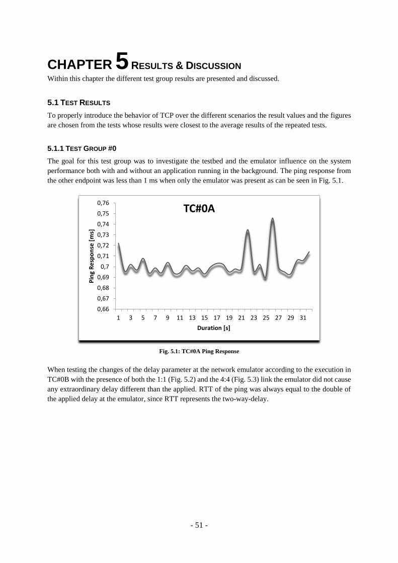
- 51 -
CHAPTER 5 RESULTS & DISCUSSION Within this chapter the different test group results are presented and discussed.
5.1 TEST RESULTS
To properly introduce the behavior of TCP over the different scenarios the result values and the figures
are chosen from the tests whose results were closest to the average results of the repeated tests.
5.1.1 TEST GROUP #0
The goal for this test group was to investigate the testbed and the emulator influence on the system
performance both with and without an application running in the background. The ping response from
the other endpoint was less than 1 ms when only the emulator was present as can be seen in Fig. 5.1.
Fig. 5.1: TC#0A Ping Response
When testing the changes of the delay parameter at the network emulator according to the execution in
TC#0B with the presence of both the 1:1 (Fig. 5.2) and the 4:4 (Fig. 5.3) link the emulator did not cause
any extraordinary delay different than the applied. RTT of the ping was always equal to the double of
the applied delay at the emulator, since RTT represents the two-way-delay.
0,66
0,67
0,68
0,69
0,7
0,71
0,72
0,73
0,74
0,75
0,76
1 3 5 7 9 11 13 15 17 19 21 23 25 27 29 31
Pin
g R
esp
on
se [
ms]
Duration [s]
TC#0A
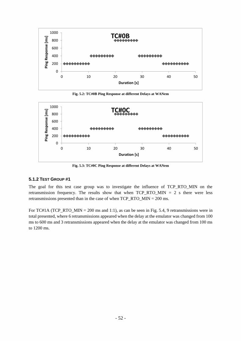
- 52 -
Fig. 5.2: TC#0B Ping Response at different Delays at WANem
Fig. 5.3: TC#0C Ping Response at different Delays at WANem
5.1.2 TEST GROUP #1
The goal for this test case group was to investigate the influence of TCP_RTO_MIN on the
retransmission frequency. The results show that when TCP_RTO_MIN = 2 s there were less
retransmissions presented than in the case of when TCP_RTO_MIN = 200 ms.
For TC#1A (TCP_RTO_MIN = 200 ms and 1:1), as can be seen in Fig. 5.4, 9 retransmissions were in
total presented, where 6 retransmissions appeared when the delay at the emulator was changed from 100
ms to 600 ms and 3 retransmissions appeared when the delay at the emulator was changed from 100 ms
to 1200 ms.
0
200
400
600
800
1000
0 10 20 30 40 50
Pin
g R
esp
on
se [
ms]
Duration [s]
TC#0B
0
200
400
600
800
1000
0 10 20 30 40 50
Pin
g R
esp
on
se [
ms]
Duration [s]
TC#0C
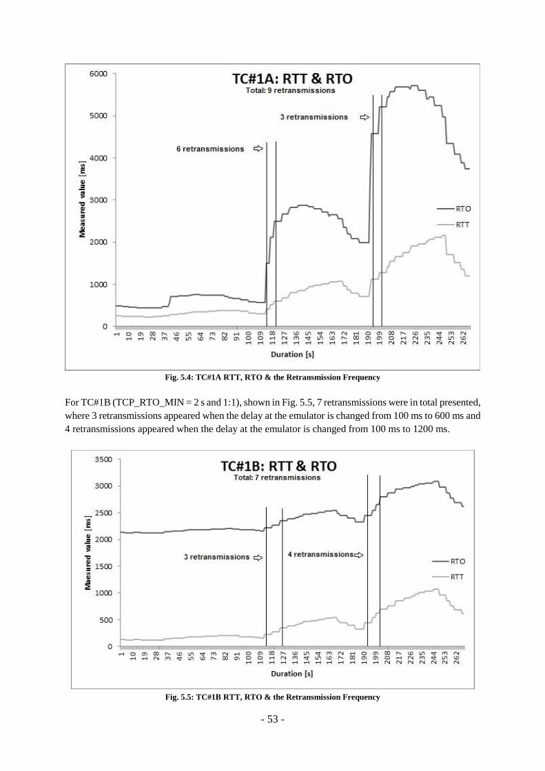
- 53 -
Fig. 5.4: TC#1A RTT, RTO & the Retransmission Frequency
For TC#1B (TCP_RTO_MIN = 2 s and 1:1), shown in Fig. 5.5, 7 retransmissions were in total presented,
where 3 retransmissions appeared when the delay at the emulator is changed from 100 ms to 600 ms and
4 retransmissions appeared when the delay at the emulator is changed from 100 ms to 1200 ms.
Fig. 5.5: TC#1B RTT, RTO & the Retransmission Frequency
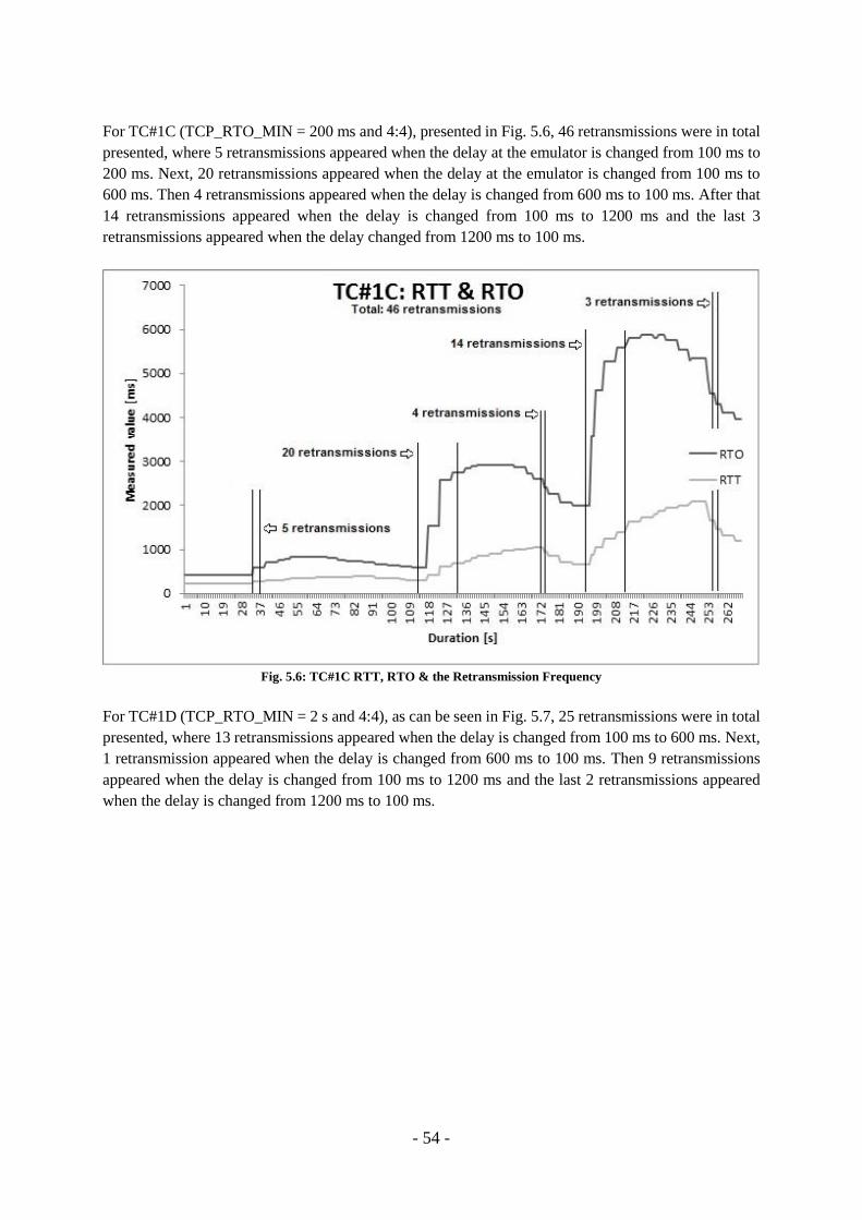
- 54 -
For TC#1C (TCP_RTO_MIN = 200 ms and 4:4), presented in Fig. 5.6, 46 retransmissions were in total
presented, where 5 retransmissions appeared when the delay at the emulator is changed from 100 ms to
200 ms. Next, 20 retransmissions appeared when the delay at the emulator is changed from 100 ms to
600 ms. Then 4 retransmissions appeared when the delay is changed from 600 ms to 100 ms. After that
14 retransmissions appeared when the delay is changed from 100 ms to 1200 ms and the last 3
retransmissions appeared when the delay changed from 1200 ms to 100 ms.
Fig. 5.6: TC#1C RTT, RTO & the Retransmission Frequency
For TC#1D (TCP_RTO_MIN = 2 s and 4:4), as can be seen in Fig. 5.7, 25 retransmissions were in total
presented, where 13 retransmissions appeared when the delay is changed from 100 ms to 600 ms. Next,
1 retransmission appeared when the delay is changed from 600 ms to 100 ms. Then 9 retransmissions
appeared when the delay is changed from 100 ms to 1200 ms and the last 2 retransmissions appeared
when the delay is changed from 1200 ms to 100 ms.
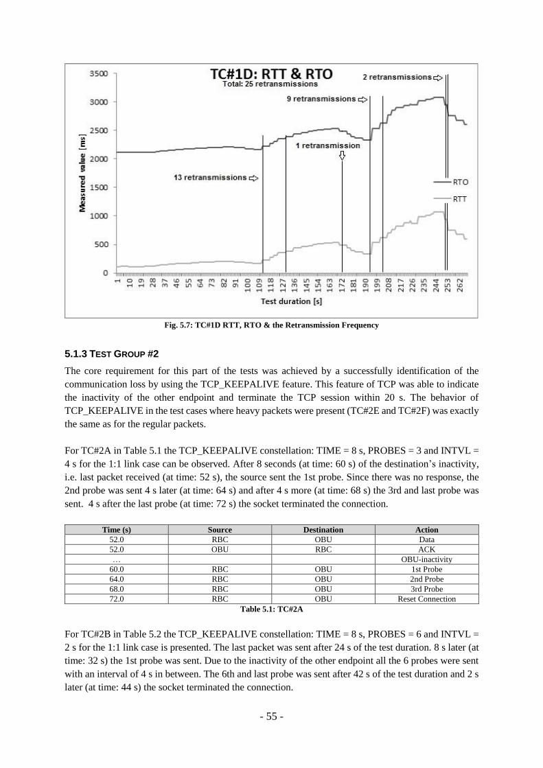
- 55 -
Fig. 5.7: TC#1D RTT, RTO & the Retransmission Frequency
5.1.3 TEST GROUP #2
The core requirement for this part of the tests was achieved by a successfully identification of the
communication loss by using the TCP_KEEPALIVE feature. This feature of TCP was able to indicate
the inactivity of the other endpoint and terminate the TCP session within 20 s. The behavior of
TCP_KEEPALIVE in the test cases where heavy packets were present (TC#2E and TC#2F) was exactly
the same as for the regular packets.
For TC#2A in Table 5.1 the TCP_KEEPALIVE constellation: TIME = 8 s, PROBES = 3 and INTVL =
4 s for the 1:1 link case can be observed. After 8 seconds (at time: 60 s) of the destination’s inactivity,
i.e. last packet received (at time: 52 s), the source sent the 1st probe. Since there was no response, the
2nd probe was sent 4 s later (at time: 64 s) and after 4 s more (at time: 68 s) the 3rd and last probe was
sent. 4 s after the last probe (at time: 72 s) the socket terminated the connection.
Time (s) Source Destination Action
52.0 RBC OBU Data
52.0 OBU RBC ACK
… OBU-inactivity
60.0 RBC OBU 1st Probe
64.0 RBC OBU 2nd Probe
68.0 RBC OBU 3rd Probe
72.0 RBC OBU Reset Connection
Table 5.1: TC#2A
For TC#2B in Table 5.2 the TCP_KEEPALIVE constellation: TIME = 8 s, PROBES = 6 and INTVL =
2 s for the 1:1 link case is presented. The last packet was sent after 24 s of the test duration. 8 s later (at
time: 32 s) the 1st probe was sent. Due to the inactivity of the other endpoint all the 6 probes were sent
with an interval of 4 s in between. The 6th and last probe was sent after 42 s of the test duration and 2 s
later (at time: 44 s) the socket terminated the connection.

- 56 -
Time (s) Source Destination Action
24.0 RBC OBU Data
24.0 OBU RBC ACK
… OBU inactivity
32.0 RBC OBU 1st Probe
34.0 RBC OBU 2nd Probe
36.0 RBC OBU 3rd Probe
38.0 RBC OBU 4th Probe
40.0 RBC OBU 5th Probe
42.0 RBC OBU 6th Probe
44.0 RBC OBU Reset Connection
Table 5.2: TC#2B
For TC#2C and TC#2E in Table 5.3 the TCP_KEEPALIVE constellation: TIME = 8 s, PROBES = 3,
INTVL = 4 s for the 4:4 link case is illustrated. Both TC#2C and TC#2E are presented here since the
tests did not show any difference between the transmission of the regular packets and the heavier
packets. Since there are four links and in total 12 probes are presented, where each connection uses 3
probes each, before each consecutive socket terminates its session.
Time (s) Source Destination Action
23.9 RBC1 OBU1 Data
24.1 OBU1 RBC1 ACK
24.3 RBC2 OBU2 Data
24.6 OBU2 RBC2 ACK
26.4 RBC3 OBU3 Data
26.6 OBU3 RBC3 ACK
28.4 RBC4 OBU4 Data
28.7 OBU4 RBC4 ACK
32.2 RBC1 OBU1 1st Probe
32.6 RBC2 OBU2 1st Probe
34.6 RBC3 OBU3 1st Probe
36.2 RBC1 OBU1 2nd Probe
36.6 RBC2 OBU2 2nd Probe
36.7 RBC4 OBU4 1st Probe
38.6 RBC3 OBU3 2nd Probe
40.2 RBC1 OBU1 3rd Probe
40.6 RBC2 OBU2 3rd Probe
40.7 RBC4 OBU4 2nd Probe
42.6 RBC3 OBU3 3rd Probe
44.2 RBC1 OBU1 Reset Connection
44.6 RBC2 OBU2 Reset Connection
44.7 RBC4 OBU4 3rd Probe
46.7 RBC3 OBU3 Reset Connection
48.7 RBC4 OBU4 Reset Connection
Table 5.3: TC#2C & TC#2E
For TC#2D and TC#2F in Table 5.4 the TCP_KEEPALIVE constellation: TIME = 8 s, PROBES = 6,
INTVL = 2 s for the 4:4 link case is illustrated. Both TC#2D and TC#2F are presented here since the
tests did not show any difference between the transmission of the regular packets and the heavier
packets. Since there are four links and in total 24 probes are presented, where each connection uses 6
probes each, before each consecutive socket terminates its session.
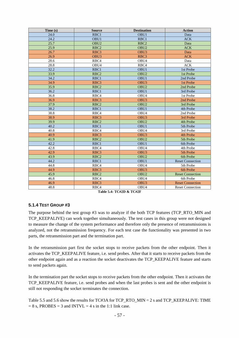
- 57 -
Time (s) Source Destination Action
24.0 RBC1 OBU1 Data
24.2 OBU1 RBC1 ACK
25.7 OBU2 RBC2 Data
25.9 RBC2 OBU2 ACK
26.7 RBC3 OBU3 Data
26.9 OBU3 RBC3 ACK
28.6 RBC4 OBU4 Data
28.8 OBU4 RBC4 ACK
32.2 RBC1 OBU1 1st Probe
33.9 RBC2 OBU2 1st Probe
34.2 RBC1 OBU1 2nd Probe
34.9 RBC3 OBU3 1st Probe
35.9 RBC2 OBU2 2nd Probe
36.2 RBC1 OBU1 3rd Probe
36.8 RBC4 OBU4 1st Probe
36.9 RBC3 OBU3 2nd Probe
37.9 RBC2 OBU2 3rd Probe
38.2 RBC1 OBU1 4th Probe
38.8 RBC4 OBU4 2nd Probe
38.9 RBC3 OBU3 3rd Probe
39.9 RBC2 OBU2 4th Probe
40.2 RBC1 OBU1 5th Probe
40.8 RBC4 OBU4 3rd Probe
40.9 RBC3 OBU3 4th Probe
41.9 RBC2 OBU2 5th Probe
42.2 RBC1 OBU1 6th Probe
42.8 RBC4 OBU4 4th Probe
42.9 RBC3 OBU3 5th Probe
43.9 RBC2 OBU2 6th Probe
44.2 RBC1 OBU1 Reset Connection
44.8 RBC4 OBU4 5th Probe
44.9 RBC3 OBU3 6th Probe
45.9 RBC2 OBU2 Reset Connection
46.8 RBC4 OBU4 6th Probe
46.9 RBC3 OBU3 Reset Connection
48.8 RBC4 OBU4 Reset Connection
Table 5.4: TC#2D & TC#2F
5.1.4 TEST GROUP #3
The purpose behind the test group #3 was to analyze if the both TCP features (TCP_RTO_MIN and
TCP_KEEPALIVE) can work together simultaneously. The test cases in this group were not designed
to measure the change of the system performance and therefore only the presence of retransmissions is
analyzed, not the retransmission frequency. For each test case the functionality was presented in two
parts, the retransmission part and the termination part.
In the retransmission part first the socket stops to receive packets from the other endpoint. Then it
activates the TCP_KEEPALIVE feature, i.e. send probes. After that it starts to receive packets from the
other endpoint again and as a reaction the socket deactivates the TCP_KEEPALIVE feature and starts
to send packets again.
In the termination part the socket stops to receive packets from the other endpoint. Then it activates the
TCP_KEEPALIVE feature, i.e. send probes and when the last probes is sent and the other endpoint is
still not responding the socket terminates the connection.
Table 5.5 and 5.6 show the results for TC#3A for TCP_RTO_MIN = 2 s and TCP_KEEPALIVE: TIME
= 8 s, PROBES = 3 and INTVL = 4 s in the 1:1 link case.
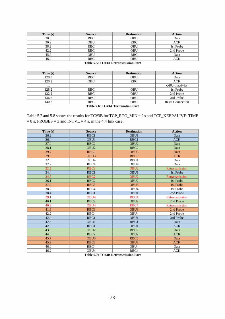
- 58 -
Time (s) Source Destination Action
30.0 RBC OBU Data
30.2 OBU RBC ACK
38.2 RBC OBU 1st Probe
42.2 RBC OBU 2nd Probe
45.9 OBU RBC Data
46.0 RBC OBU ACK
Table 5.5: TC#3A Retransmission Part
Time (s) Source Destination Action
120.0 RBC OBU Data
120.2 OBU RBC ACK
… OBU-inactivity
128.2 RBC OBU 1st Probe
132.2 RBC OBU 2nd Probe
136.2 RBC OBU 3rd Probe
140.2 RBC OBU Reset Connection
Table 5.6: TC#3A Termination Part
Table 5.7 and 5.8 shows the results for TC#3B for TCP_RTO_MIN = 2 s and TCP_KEEPALIVE: TIME
= 8 s, PROBES = 3 and INTVL = 4 s. in the 4:4 link case.
Time (s) Source Destination Action
26.2 RBC1 OBU1 Data
26.4 OBU1 RBC1 ACK
27.9 RBC2 OBU2 Data
28.1 OBU2 RBC2 Data
29.7 RBC3 OBU3 Data
29.9 OBU3 RBC3 ACK
32.0 OBU4 RBC4 Data
32.2 RBC4 OBU4 Data
32.5 RBC2 OBU2 Retransmission
34.4 RBC1 OBU1 1st Probe
34.7 RBC2 OBU2 Retransmission
36.1 RBC2 OBU2 1st Probe
37.9 RBC3 OBU3 1st Probe
38.2 RBC4 OBU4 1st Probe
38.4 RBC1 OBU1 2nd Probe
39.1 OBU4 RBC4 Retransmission
40.1 RBC2 OBU2 2nd Probe
40.3 OBU4 RBC4 Retransmission
41.9 RBC3 OBU3 2nd Probe
42.2 RBC4 OBU4 2nd Probe
42.4 RBC1 OBU1 3rd Probe
42.6 OBU1 RBC1 Data
42.8 RBC1 OBU1 ACK
43.8 OBU2 RBC2 Data
44.0 RBC2 OBU2 ACK
45.7 OBU3 RBC3 Data
45.9 RBC3 OBU3 ACK
46.0 RBC4 OBU4 Data
46.2 OBU4 RBC4 ACK
Table 5.7: TC#3B Retransmission Part
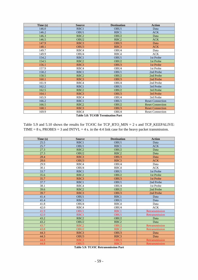
- 59 -
Time (s) Source Destination Action
146.0 RBC1 OBU1 Data
146.2 OBU1 RBC1 ACK
146.3 RBC2 OBU2 Data
146.5 OBU2 RBC2 ACK
147.9 RBC3 OBU3 Data
148.1 OBU3 RBC3 ACK
149.7 RBC4 OBU4 Data
149.9 OBU4 RBC4 ACK
154.2 RBC1 OBU1 1st Probe
154.5 RBC2 OBU2 1st Probe
156.1 RBC3 OBU3 1st Probe
157.9 RBC4 OBU4 1st Probe
158.2 RBC1 OBU1 2nd Probe
158.5 RBC2 OBU2 2nd Probe
160.1 RBC3 OBU3 2nd Probe
161.9 RBC4 OBU4 2nd Probe
162.2 RBC1 OBU1 3rd Probe
162.5 RBC2 OBU2 3rd Probe
164.1 RBC3 OBU3 3rd Probe
165.9 RBC4 OBU4 3rd Probe
166.2 RBC1 OBU1 Reset Connection
166.5 RBC2 OBU2 Reset Connection
168.1 RBC3 OBU3 Reset Connection
169.9 RBC4 OBU4 Reset Connection
Table 5.8: TC#3B Termination Part
Table 5.9 and 5.10 shows the results for TC#3C for TCP_RTO_MIN = 2 s and TCP_KEEPALIVE:
TIME = 8 s, PROBES = 3 and INTVL = 4 s. in the 4:4 link case for the heavy packet transmission.
Time (s) Source Destination Action
25.5 RBC1 OBU1 Data
25.7 OBU1 RBC1 ACK
27.3 RBC2 OBU2 Data
27.3 OBU2 RBC2 Data
28.4 RBC3 OBU3 Data
28.6 OBU3 RBC3 ACK
29.9 RBC4 OBU4 Data
30.1 OBU4 RBC4 ACK
33.7 RBC1 OBU1 1st Probe
35.6 RBC2 OBU2 1st Probe
35.7 RBC3 OBU3 1st Probe
37.7 RBC1 OBU1 2nd Probe
38.1 RBC4 OBU4 1st Probe
39.6 RBC2 OBU2 2nd Probe
39.7 RBC3 OBU3 2nd Probe
41.4 OBU1 RBC1 Data
41.4 RBC1 OBU1 Data
41.8 OBU4 RBC4 Data
42.0 RBC4 OBU4 ACK
41.9 OBU1 RBC1 Retransmission
42.0 RBC1 OBU1 Retransmission
43.2 RBC2 OBU2 Data
43.2 OBU2 RBC2 Data
43.7 RBC2 OBU2 Retransmission
43.8 OBU2 RBC2 Retransmission
44.3 RBC3 OBU3 Data
44.3 OBU3 RBC3 Data
44.8 RBC3 OBU3 Retransmission
44.8 OBU3 RBC3 Retransmission
Table 5.9: TC#3C Retransmission Part
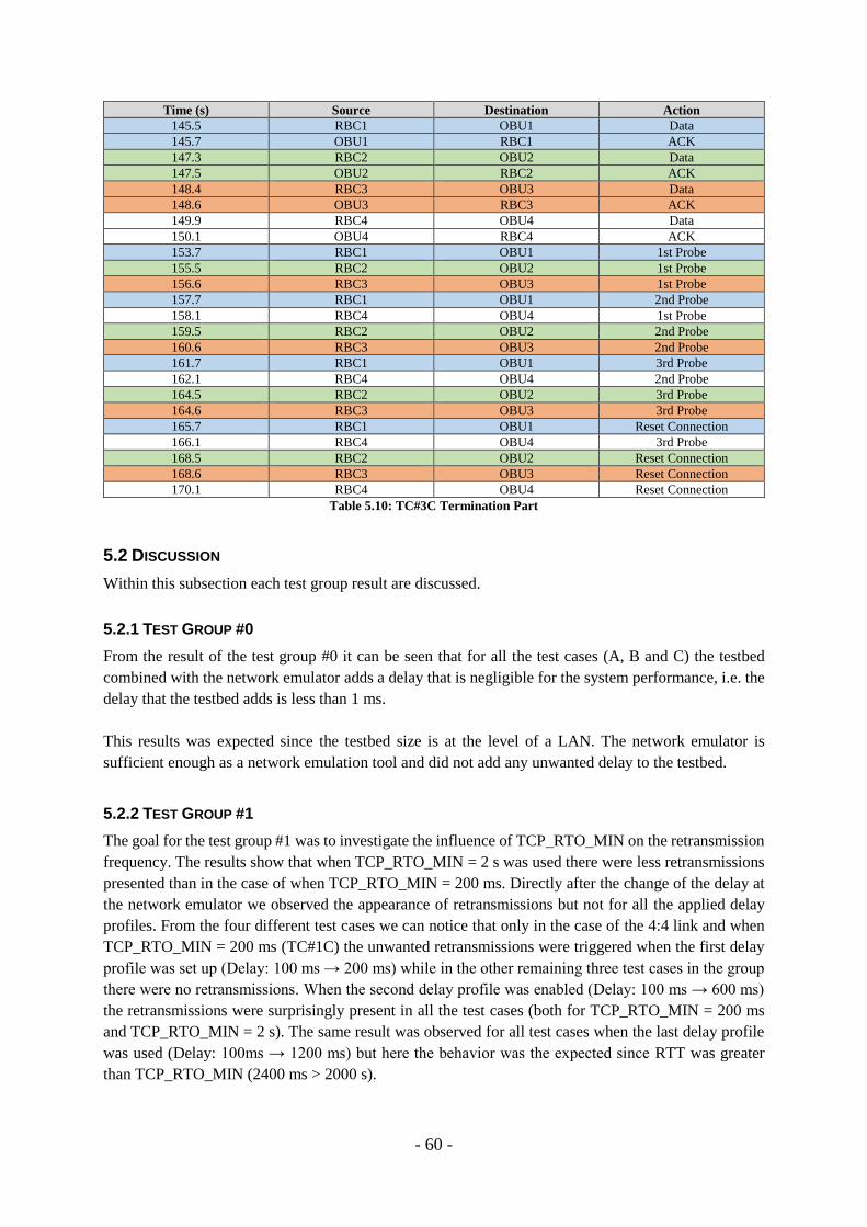
- 60 -
Time (s) Source Destination Action
145.5 RBC1 OBU1 Data
145.7 OBU1 RBC1 ACK
147.3 RBC2 OBU2 Data
147.5 OBU2 RBC2 ACK
148.4 RBC3 OBU3 Data
148.6 OBU3 RBC3 ACK
149.9 RBC4 OBU4 Data
150.1 OBU4 RBC4 ACK
153.7 RBC1 OBU1 1st Probe
155.5 RBC2 OBU2 1st Probe
156.6 RBC3 OBU3 1st Probe
157.7 RBC1 OBU1 2nd Probe
158.1 RBC4 OBU4 1st Probe
159.5 RBC2 OBU2 2nd Probe
160.6 RBC3 OBU3 2nd Probe
161.7 RBC1 OBU1 3rd Probe
162.1 RBC4 OBU4 2nd Probe
164.5 RBC2 OBU2 3rd Probe
164.6 RBC3 OBU3 3rd Probe
165.7 RBC1 OBU1 Reset Connection
166.1 RBC4 OBU4 3rd Probe
168.5 RBC2 OBU2 Reset Connection
168.6 RBC3 OBU3 Reset Connection
170.1 RBC4 OBU4 Reset Connection
Table 5.10: TC#3C Termination Part
5.2 DISCUSSION
Within this subsection each test group result are discussed.
5.2.1 TEST GROUP #0
From the result of the test group #0 it can be seen that for all the test cases (A, B and C) the testbed
combined with the network emulator adds a delay that is negligible for the system performance, i.e. the
delay that the testbed adds is less than 1 ms.
This results was expected since the testbed size is at the level of a LAN. The network emulator is
sufficient enough as a network emulation tool and did not add any unwanted delay to the testbed.
5.2.2 TEST GROUP #1
The goal for the test group #1 was to investigate the influence of TCP_RTO_MIN on the retransmission
frequency. The results show that when TCP_RTO_MIN = 2 s was used there were less retransmissions
presented than in the case of when TCP_RTO_MIN = 200 ms. Directly after the change of the delay at
the network emulator we observed the appearance of retransmissions but not for all the applied delay
profiles. From the four different test cases we can notice that only in the case of the 4:4 link and when
TCP_RTO_MIN = 200 ms (TC#1C) the unwanted retransmissions were triggered when the first delay
profile was set up (Delay: 100 ms → 200 ms) while in the other remaining three test cases in the group
there were no retransmissions. When the second delay profile was enabled (Delay: 100 ms → 600 ms)
the retransmissions were surprisingly present in all the test cases (both for TCP_RTO_MIN = 200 ms
and TCP_RTO_MIN = 2 s). The same result was observed for all test cases when the last delay profile
was used (Delay: 100ms → 1200 ms) but here the behavior was the expected since RTT was greater
than TCP_RTO_MIN (2400 ms > 2000 s).

- 61 -
In Fig. 5.5 and Fig. 5.7 we can notify that when TCP_RTO_MIN = 2 s was applied, the retransmission
were triggered under the second delay profile even though the estimated RTO value was much greater
than the actual RTT.
The performance was predicted to be lower for a higher number of links, i.e. the 4:4 case should have
more retransmissions than the 1:1 case and it is clearly shown in the results. It is also important to
highlight the decrease of the number of retransmissions for one link when using the same link
constellation but over the different TCP_RTO_MIN values.
For the 1:1 case (TC#1A and TC#1B) an improvement in performance can be seen in a reduced number
of retransmissions, i.e. 23% less retransmissions appeared in the case of TCP_RTO_MIN = 2 s when
compared to the default TCP_RTO_MIN. In addition, it should be stated that for TCP_RTO_MIN = 2
s the retransmissions are not omitted when the channel delay was at the level of 1200 ms (600 ms delay
profile) and 2400 ms (1200 ms delay profile). When considering the 1200 ms delay case it should not
trigger retransmissions since 1200 ms < 2000 ms, but those were triggered.
For the 4:4 case (TC#1C and TC#1D) the improvement in the system performance was significantly
higher than in the 1:1 case, i.e. for this case 46% less retransmissions appeared when TCP_RTO_MIN
= 2 s.
Increasing TCP_RTO_MIN value from 200 ms to 2 s means that TCP becomes more patient and does
not send retransmissions for small channel delays compared to TCP_RTO_MIN. Since the modified
parameter does not exist in the RTO algorithm that is described in RFC, it is possible that its role in the
RTO computation is more complex than we assumed and the further, a more deep analysis of the TCP
implementation within the system kernel is required.
Our explanation for why the retransmissions are triggered even in the case of the 1200 ms channel delay
is that the final RTO value depends on both the previous RTO and the new measured RTT. Our
assumption is that the recommended values for alpha and beta (according to the formula in Section
2.5.3) should probably be lowered to focus more on the past values and make TCP reacting slower to
the changes in the channel since the specific nature of the communication in the train-trackside scenario
does not require such an aggressive attitude from the transmission protocol.
For TCP_RTO_MIN itself it is possible that this parameter becomes highly efficient when the
operational scenario is related to more modern systems that works with a high throughput of data over
very low RTT connections (like the data centers and the SANs). If the achieved RTTs are far below 100
ms then the TCP should obviously not follow the typical behavior and set the RTO to 1s. Instead it may
probably use a custom parameter (like TCP_RTO_MIN) that defines the lower bound for the
retransmission timeout. Based on that conclusion our effort of modifying TCP_RTO_MIN for the rather
slow emulated wireless connection in the train-trackside scenario was partly unsuccessful.
5.2.3 TEST GROUP #2
The TCP_KEEPALIVE feature is sufficient for controlling the link state and is very flexible since it can
be updated on a live system, i.e. there is no need of complex and time consuming kernel operations.
- 62 -
5.2.4 TEST GROUP #3
In all the test cases we found that when the channel delay is 10 s TCP_KEEPALIVE starts to send probes
and when the delayed packets finally arrives TCP_KEEPALIVE is correctly switched off. This is
because the other endpoint is still active but the transmission is delayed by the applied 10 s so it takes
up to 16 s for the POS message to travel through the link. Later when the 100% loss is applied at the
network emulator the TCP_KEEPALIVE feature is activated again and after sending the last probe TCP
terminates the connection.
One negative thing that we discovered was that when using the same socket for both sending and
receiving the TCP retransmission mechanism will override the TCP_KEEPALIVE timers
(TCP_KEEPALIVE_TIME and TCP_KEEPALIVE_INTVL) so even though the communication is
down, the retransmissions from the sending thread will prevent TCP_KEEPALIVE from closing the
socket.
TCP is possible to be tuned for the sake of a specific type of scenarios like the wireless train-trackside
communication. By changing the TCP_RTO_MIN values the protocol might react slower to the
instantaneous (and short in magnitude) changes of the radio link performance and therefore less
retransmission could be triggered. The TCP_KEEPALIVE mechanism is possible to be enabled as a
link state monitoring feature that can close the socket and notify the higher layers (application) before
the reaction from the lower layers.
Another important conclusion is the ethical aspects of customizing TCP that is operating over a common
thing like the Internet. It is a very popular opinion that the wide scale functionality of TCP that includes
its design, analysis and implementation, should be performed in a way of discussion among the wide
public authority.
- 63 -
CHAPTER 6 REPORT CLOSURE An overview of the discussed conclusions and the possible future works are provided in this section.
6.1 CONCLUSIONS
The main objective of this thesis was to modify the part of the TCP functionality for the purposes of a
wireless transmission over a railway specific scenario. The communication link between a traveling
train and its corresponding control center has an infrequent and periodic characteristics, which is also
event-driven and time-related. In a train control system small messages are exchanged over a
narrowband channel. The specific properties of this link were analyzed and subsequently imitated using
a simple network emulator. The traffic model was realized by two constellations of the custom client-
server applications: a single pair of the RBC-OBU instances and a four independent pairs of the similar
RBC-OBU instances, which have emulated the system under load. The actual protocol evaluation idea
was concerning a modification of one of the two OS kernel features (TCP_RTO_MIN).
6.1.1 TCP_RTO_MIN
This feature was expected to be a limiting lower bound of the TCP’s retransmission timeout (RTO),
which should be implemented in nowadays systems to meet the requirements from the modern most
demanding network solutions (e.g. SANs) as it was introduced in [18] from the Related Works section.
Our solution was based on the assumption: if in cutting-edge technologies the achieved ultra-low RTTs
(<1 ms, described in [18]) justifies the resignation of the fixed and inadequate TCP_RTO_MIN (equal
to 1 s and recommended by RFC), then perhaps a higher TCP_RTO_MIN than the default value could
mitigate the influence of a noisy channel on the radio transmission in the train-trackside scenario. After
applying this update, TCP should become more patient and send less retransmissions and in this way
improve the overall system performance. This goal of the thesis was achieved since we managed to
change the TCP_RTO_MIN in the system by a complex kernel recompilation.
When TCP_RTO_MIN = 2 s, the results show a decreased number of retransmission compared to the
default value when TCP_RTO_MIN = 200 ms. However, the results were not as good as expected. Even
though the log from the current socket was showing the RTO much higher than the applied at the
network emulator delay, some spurious retransmissions were still presented. Overall, the percentage of
retransmissions decreased when the tests were performed in the higher link constellation case (4:4).
Our motivation for the first finding is that the TCP implementation in the OS kernel is a complex
structure dispersed over many smaller parts which interact with each other (e.g. when RTO is computed)
making it difficult to trace all the required paths that the modification procedure should follow. Probably
TCP_RTO_MIN becomes somewhere overwritten by the one second value that is suggested by RFC
and our update did not cover this situation.
Secondly, TCP_RTO_MIN is not present in the RTO algorithm defined in RFC, since it was originally
introduced as an enhancement for solutions that offer much lower RTTs. It is highly possible that
somewhere in the code of the RTO algorithm, the computed value is directly compared with the default
“1 s minimum” and only when it is smaller (i.e. high throughput system is present) the RTO_MIN
feature is enabled. We also find a strong motivation for the harmful influence of RTTVAR (round trip
- 64 -
time variance), when there is a noticeable difference between a measured RTT and the updated
RTO_MIN value (2 s).
The reason for the performance improvement observed in the higher constellation is that when the
system approaches its theoretical capacity (i.e. when the load feature of the four links was presented),
TCP_RTO_MIN gains the higher priority over the default “1 s minimum” rule making our modification
efficient. However, this uncertainty requires further analysis of the problem of the TCP source code
fragmentation, which was not possible to perform during the limited time of this project.
6.1.2 TCP_KEEPALIVE
The secondary objective of this research was concerning the link state functionality of TCP. In the
communication session in a train-trackside scenario, where TCP operates as a bearer over a wireless
channel, the transport layer protocol should be able to indicate a loss of communication within 20 s. If
this could be achieved without the involvement of the lower layer protocols, the total time needed to
reestablish the connection would be reduced by removing the unnecessary system downtime. TCP
provides an option to monitor the state of the link by the functionality related to the TCP_KEEPALIVE
setup. However, the default configuration of TCP_KEEPALIVE, which is enabled in the system, works
highly inefficiently for our scenario, i.e. it takes 2 hours (7200 s) to react for the possible loss of the link.
We managed to change TCP_KEEPALIVE so that the communication session is terminated after 20 s
of the other endpoint’s inactivity. This update was possible to perform on the live system (the feature
instructions are not hardcoded in the OS kernel) and the complexity of that operation is negligible.
However, the TCP_KEEPALIVE feature has to be requested by the application itself and is not provided
by default, even though it is enabled at the system level.
6.1.3 GENERAL
The general conclusion is that TCP, despite being a very mature protocol, is still tunable when there is
the possibility of using it in new scenarios. The train-trackside case that will utilize TCP over a wireless
medium could definitely benefit from the modifications of the protocol retransmission and the link state
features that are proposed in this paper. Due to the higher chance for instantaneous and short changes in
the radio channel properties, the supporting protocol should not completely follow its original principles,
which were defined for wire-based links.
By applying suggested changes to modify the fixed TCP_RTO_MIN and TCP_KEEPALIVE, the
overall performance of the train control system will be improved, since it will make the system to work
more consistently. The modification of TCP_RTO_MIN makes the system to react less aggressively to
the short and instantaneous changes in the channel, while the modification of TCP_KEEPALIVE allows
the system to react faster for the true loss of communication.
Since the train scenario that is covered in this paper does not utilize the bursty transmission with high
bitrates, the drawbacks of the Forward Error Correction presented in [16] and used in GPRS have
negligible impact on the system performance. Our proposed modification of TCP_RTO_MIN noticeably
improves the behavior of TCP congestion control performance over a fitful radio link. Even though that
change is not dynamic, which was suggested in the conclusion of [17], it still enhances the overall system
work consistency. In addition, as a contradiction to the findings in [19] we have found a scenario, where
- 65 -
a specific combination of smaller values of alpha and beta in RTO, could optimize the behavior of TCP.
This idea requires further research, which was not possible to perform during our thesis.
One more important issue that is worth to mention is the direct improvement to the overall service
security that should be observed if our suggestions for TCP modernization would be implemented. In
case of an unexpected event (e.g. a train disaster) during the bad channel conditions (e.g. trains travelling
within a storm) the reduced number of retransmissions will release the resources for Emergency
Messages (a group call feature) allowing them to travel without unwanted delays making important
reaction to be performed as soon as possible.
The conclusions from our report provide another argument that justifies the migration towards a packet-
switched technology in the “EoG” venture.
6.2 FUTURE WORK
During the project development we faced several obstacles that led to the final shape of this thesis. We
were able to solve many of them but some questions still remain unanswered due to the resource
limitations. Here we present the potential candidates for the future studies and some recommendations
for possible solutions, which could be worth to analyze.
The parameters (alpha and beta) that are mentioned in RFC, presented in the RTO formula and
responsible for controlling the relation between the past and the current measurement of RTO should be
analyzed more accurately.
As mentioned in the project limitations we focused only on one specific TCP dialect, its implementation
and functionality in a chosen OS environment. The proposed tests could be repeated for different TCP
dialects.
From the wide spectrum of the open source Linux distribution we decided to investigate the mechanisms
implemented in Ubuntu. There is a strong motivation to compare the TCP implementation over different
Linux distributions (e.g. RedHat), which possibly might provide access to TCP_RTO_MIN from the
live system level and there is no need of a time consuming kernel recompilation.
The TCP implementation within the Ubuntu kernel is complex, i.e. with the structure of the nested
functions that computes RTO using a range of different optional parameters like timestamp etc. Hence,
the idea of the protocol optimization could be developed over a few more separate thesis projects. If
RFC recommends in the most actual version that for smaller RTTs, RTO should be set to 1 s, an
interesting approach might be to localize this one specific instruction in the TCP code and set it to the
upper value if it is required by any other specific scenario.
Bombardier can proceed with our results and perform more complex on-truck tests using a real GPRS
link in a real train-trackside environment. An extended scenario should focus on the influence of a higher
number of trains operating within a close neighborhood on the communication link performance.

- 66 -
- 67 -
REFERENCES
[1] WINTER, P. et al. (eds.) (2009) Compendium on ERTMS. Eurail Press.
[2] RUESCHE, S. STEUER, J. & JOBMANN, K. (2008) The European Switch - A packet-Switched
Approach to a Train Control System. IEEE Vehicular Technology Magazine. [ONLINE] Available at:
http://ieeexplore.ieee.org/xpl/articleDetails.jsp?arnumber=4682516&newsearch=true&queryText=The
%20European%20Switch%20-%20A%20packet-
Switched%20Approach%20to%20a%20Train%20Control%20System. [Last Accessed at: 14
November 2015].
[3] GHRIBI, B. LOGRIPPO, L. (2000) Understanding GPRS - The GSM Packet Radio Service.
Computer Networks 34. [ONLINE] Available at:
http://citeseerx.ist.psu.edu/viewdoc/download?doi=10.1.1.20.7349&rep=rep1&type=pdf. [Last
Accessed: 14 November 2015].
[4] Tutorialspoint GPRS Tutorial. [ONLINE] Available at:
http://www.tutorialspoint.com/gprs/gprs_quick_guide.htm. [Last Accessed: 14 November 2015].
[5] EventHelix.com. (2005). GPRS Attach and PDP Context Activation for a Class B Terminal.
[ONLINE] Available at:
https://www.eventhelix.com/RealtimeMantra/Telecom/gprs_attach_pdp_sequence_diagram.pdf. [Last
Accessed: 14 November 2015].
[6] ZVONAR, Z. JUNG, P. KAMMERLANDER, K. (2002) GSM: Evolution towards 3rd Generation
Systems. [ONLINE] Available at:
https://books.google.se/books?id=nrTkBwAAQBAJ&pg=PA70&lpg=PA70&dq=mobile+station+cont
ext&source=bl&ots=VRksUMtx-Y&sig=NjlPd3w6N-
LtfbNqKneVhcfplpo&hl=sv&sa=X&ved=0CCcQ6AEwAWoVChMIjOmG3NnxyAIViWtyCh3IgA6
m#v=onepage&q=mobile%20station%20context&f=false. [Last Accessed: 14 November 2015].
[7] EoG Phase 2 Test Report - Bombardier*
[8] RFC 5681: ALLMAN, M. et al. (2009) TCP Congestion Control. [ONLINE] Available at:
https://www.rfc-editor.org/rfc/pdfrfc/rfc5681.txt.pdf. [Last Accessed: 14 November 2015].
[9] RFC 6298: PAXSON, V. et al. (2011) Computing TCP’s Retransmission Timer. [ONLINE]
Available at: https://www.rfc-editor.org/rfc/pdfrfc/rfc6298.txt.pdf. [Last Accessed: 14 November
2015].
- 68 -
[10] KARN, P. PARTRIDGE, C. (1995) Improving Round-Trip Time Estimates in Reliable Transport
Protocols. [ONLINE] Available at: http://ccr.sigcomm.org/archive/1995/jan95/ccr-9501-
partridge87.pdf. [Last Accessed: 14 November 2015].
[11] RFC 7323: BORMAN, D. et al. (2014) TCP Extensions for High Performance. [ONLINE]
Available at: https://www.rfc-editor.org/rfc/pdfrfc/rfc7323.txt.pdf. [Last Accessed: 14 November
2015].
[12] RFC 3522: LUDWIG, R. MEYER, M. (2003) The Eifel Detection Algorithm for TCP. [ONLINE]
Available at: https://www.rfc-editor.org/rfc/pdfrfc/rfc3522.txt.pdf. [Last Accessed: 14 November
2015].
[13] VASUDEVAN, V. et al. (2009) Safe and Effective Fine-grained TCP Retransmissions for
Datacenter Communication. [ONLINE] Available at: https://www.cs.cmu.edu/~dga/papers/incast-
sigcomm2009.pdf. [Last Accessed: 14 November 2015].
[14] GROS, S. (2012) Everything about nothing (Calculating TCP RTO …). [ONLINE] Available at:
http://sgros.blogspot.se/2012/02/calculating-tcp-rto.html. [Last Accessed: 14 November 2015].
[15] BUSATTO, F. (2007) TCP Keepalive HOWTO. [ONLINE] Available at:
http://tldp.org/HOWTO/TCP-Keepalive-HOWTO/index.html. [Last Accessed: 14 November 2015].
[16] LEFEVRE, F. VIVIER, G. (2000) Understanding TCP´s behavior over wireless links. [ONLINE]
Available at: http://ieeexplore.ieee.org/stamp/stamp.jsp?tp=&arnumber=923350. [Last Accessed: 14
November 2015].
[17] MANZ, M. LIYANAGE, K. (2013) Delay Analysis of Small IP Packets in GPRS RLC.
[ONLINE] Available at:http://ieeexplore.ieee.org/stamp/stamp.jsp?arnumber=6732033. [Last
Accessed: 14 November 2015].
[18] PSARAS, I. TSAOUSSIDIS, V. (2007) The TCP Minimum RTO Revisited [ONLINE] Available
at: http://www.ee.ucl.ac.uk/~uceeips/minrto-networking07.pdf. [Last Accessed: 14 November 2015].
[19] LOUKILI, A. et al (2012) TCP's Retransmission Timer and the Minimum RTO [ONLINE]
Available at: http://ieeexplore.ieee.org/stamp/stamp.jsp?tp=&arnumber=6289266. [Last Accessed: 14
November 2015].
[20] Traffic Model for RBC-Train Communication - Bombardier*

- 69 -
[21] NAMBIAR, M.K. (2007) WANem 1.1 Wide Area Network Emulator User Guide Performance
Engineering Research Centre. [ONLINE] Available at:
http://netcologne.dl.sourceforge.net/project/wanem/Documents/WANemv11-Setup-Guide.pdf. [Last
Accessed: 14 November 2015].
* - provided by Bombardier and due to the confidential policy of this company some of the documents
are not available for public inspection. For more detailed information please contact Jörgen Mattisson
(see Acknowledgements).

- 70 -
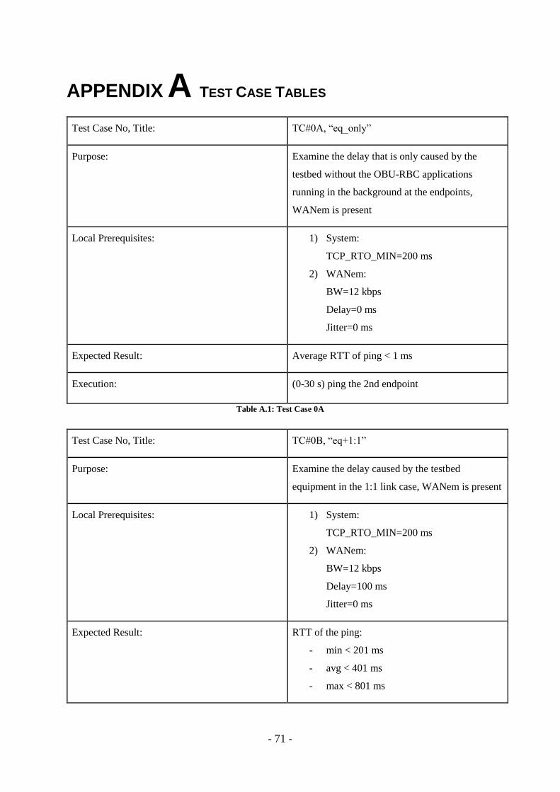
- 71 -
APPENDIX A TEST CASE TABLES
Test Case No, Title: TC#0A, “eq_only”
Purpose: Examine the delay that is only caused by the
testbed without the OBU-RBC applications
running in the background at the endpoints,
WANem is present
Local Prerequisites: 1) System:
TCP_RTO_MIN=200 ms
2) WANem:
BW=12 kbps
Delay=0 ms
Jitter=0 ms
Expected Result: Average RTT of ping < 1 ms
Execution: (0-30 s) ping the 2nd endpoint
Table A.1: Test Case 0A
Test Case No, Title: TC#0B, “eq+1:1”
Purpose: Examine the delay caused by the testbed
equipment in the 1:1 link case, WANem is present
Local Prerequisites: 1) System:
TCP_RTO_MIN=200 ms
2) WANem:
BW=12 kbps
Delay=100 ms
Jitter=0 ms
Expected Result: RTT of the ping:
- min < 201 ms
- avg < 401 ms
- max < 801 ms
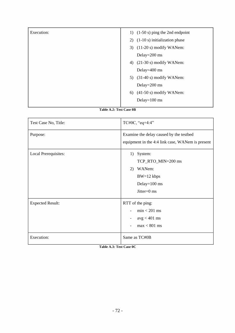
- 72 -
Execution: 1) (1-50 s) ping the 2nd endpoint
2) (1-10 s) initialization phase
3) (11-20 s) modify WANem:
Delay=200 ms
4) (21-30 s) modify WANem:
Delay=400 ms
5) (31-40 s) modify WANem:
Delay=200 ms
6) (41-50 s) modify WANem:
Delay=100 ms
Table A.2: Test Case 0B
Test Case No, Title: TC#0C, “eq+4:4”
Purpose: Examine the delay caused by the testbed
equipment in the 4:4 link case, WANem is present
Local Prerequisites: 1) System:
TCP_RTO_MIN=200 ms
2) WANem:
BW=12 kbps
Delay=100 ms
Jitter=0 ms
Expected Result: RTT of the ping:
- min < 201 ms
- avg < 401 ms
- max < 801 ms
Execution: Same as TC#0B
Table A.3: Test Case 0C
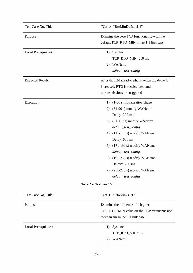
- 73 -
Test Case No, Title: TC#1A, “RtoMinDefault1:1”
Purpose: Examine the core TCP functionality with the
default TCP_RTO_MIN in the 1:1 link case
Local Prerequisites: 1) System:
TCP_RTO_MIN=200 ms
2) WANem:
default_test_config
Expected Result: After the initialization phase, when the delay is
increased, RTO is recalculated and
retransmissions are triggered
Execution: 1) (1-30 s) initialization phase
2) (31-90 s) modify WANem:
Delay=200 ms
3) (91-110 s) modify WANem:
default_test_config
4) (111-170 s) modify WANem:
Delay=600 ms
5) (171-190 s) modify WANem:
default_test_config
6) (191-250 s) modify WANem:
Delay=1200 ms
7) (251-270 s) modify WANem:
default_test_config
Table A.4: Test Case 1A
Test Case No, Title: TC#1B, “RtoMin2s1:1”
Purpose: Examine the influence of a higher
TCP_RTO_MIN value on the TCP retransmission
mechanism in the 1:1 link case
Local Prerequisites: 1) System:
TCP_RTO_MIN=2 s
2) WANem:
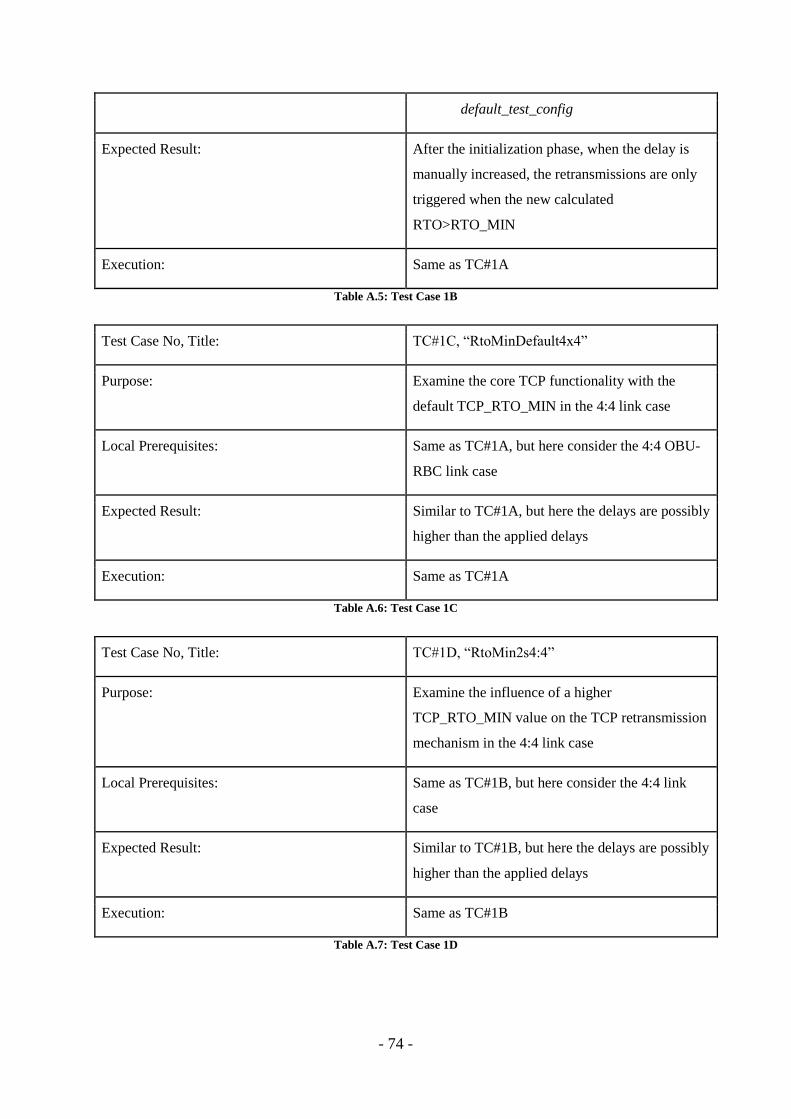
- 74 -
default_test_config
Expected Result: After the initialization phase, when the delay is
manually increased, the retransmissions are only
triggered when the new calculated
RTO>RTO_MIN
Execution: Same as TC#1A
Table A.5: Test Case 1B
Test Case No, Title: TC#1C, “RtoMinDefault4x4”
Purpose: Examine the core TCP functionality with the
default TCP_RTO_MIN in the 4:4 link case
Local Prerequisites: Same as TC#1A, but here consider the 4:4 OBU-
RBC link case
Expected Result: Similar to TC#1A, but here the delays are possibly
higher than the applied delays
Execution: Same as TC#1A
Table A.6: Test Case 1C
Test Case No, Title: TC#1D, “RtoMin2s4:4”
Purpose: Examine the influence of a higher
TCP_RTO_MIN value on the TCP retransmission
mechanism in the 4:4 link case
Local Prerequisites: Same as TC#1B, but here consider the 4:4 link
case
Expected Result: Similar to TC#1B, but here the delays are possibly
higher than the applied delays
Execution: Same as TC#1B
Table A.7: Test Case 1D
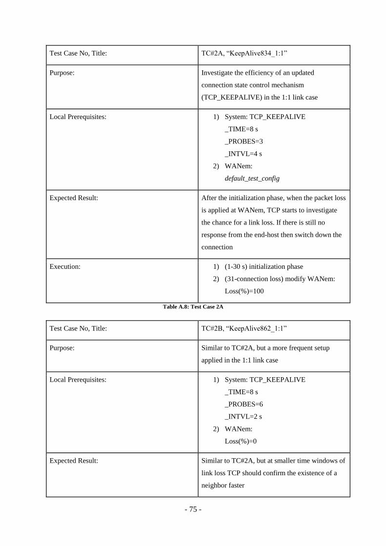
- 75 -
Test Case No, Title: TC#2A, “KeepAlive834_1:1”
Purpose: Investigate the efficiency of an updated
connection state control mechanism
(TCP_KEEPALIVE) in the 1:1 link case
Local Prerequisites: 1) System: TCP_KEEPALIVE
_TIME=8 s
_PROBES=3
_INTVL=4 s
2) WANem:
default_test_config
Expected Result: After the initialization phase, when the packet loss
is applied at WANem, TCP starts to investigate
the chance for a link loss. If there is still no
response from the end-host then switch down the
connection
Execution: 1) (1-30 s) initialization phase
2) (31-connection loss) modify WANem:
Loss(%)=100
Table A.8: Test Case 2A
Test Case No, Title: TC#2B, “KeepAlive862_1:1”
Purpose: Similar to TC#2A, but a more frequent setup
applied in the 1:1 link case
Local Prerequisites: 1) System: TCP_KEEPALIVE
_TIME=8 s
_PROBES=6
_INTVL=2 s
2) WANem:
Loss(%)=0
Expected Result: Similar to TC#2A, but at smaller time windows of
link loss TCP should confirm the existence of a
neighbor faster
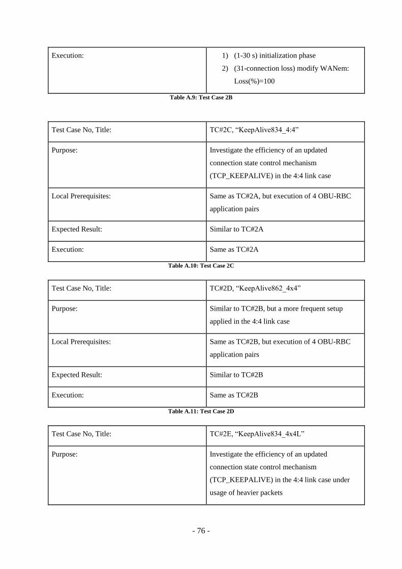
- 76 -
Execution: 1) (1-30 s) initialization phase
2) (31-connection loss) modify WANem:
Loss(%)=100
Table A.9: Test Case 2B
Test Case No, Title: TC#2C, “KeepAlive834_4:4”
Purpose: Investigate the efficiency of an updated
connection state control mechanism
(TCP_KEEPALIVE) in the 4:4 link case
Local Prerequisites: Same as TC#2A, but execution of 4 OBU-RBC
application pairs
Expected Result: Similar to TC#2A
Execution: Same as TC#2A
Table A.10: Test Case 2C
Test Case No, Title: TC#2D, “KeepAlive862_4x4”
Purpose: Similar to TC#2B, but a more frequent setup
applied in the 4:4 link case
Local Prerequisites: Same as TC#2B, but execution of 4 OBU-RBC
application pairs
Expected Result: Similar to TC#2B
Execution: Same as TC#2B
Table A.11: Test Case 2D
Test Case No, Title: TC#2E, “KeepAlive834_4x4L”
Purpose: Investigate the efficiency of an updated
connection state control mechanism
(TCP_KEEPALIVE) in the 4:4 link case under
usage of heavier packets
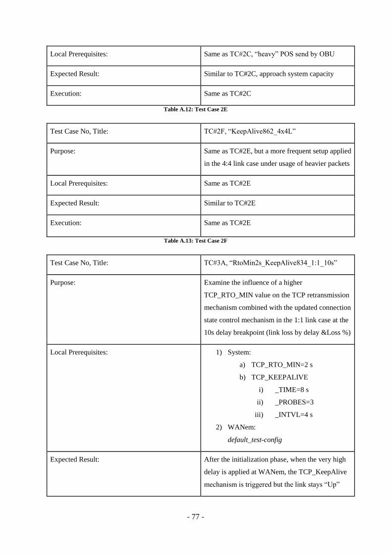
- 77 -
Local Prerequisites: Same as TC#2C, “heavy” POS send by OBU
Expected Result: Similar to TC#2C, approach system capacity
Execution: Same as TC#2C
Table A.12: Test Case 2E
Test Case No, Title: TC#2F, “KeepAlive862_4x4L”
Purpose: Same as TC#2E, but a more frequent setup applied
in the 4:4 link case under usage of heavier packets
Local Prerequisites: Same as TC#2E
Expected Result: Similar to TC#2E
Execution: Same as TC#2E
Table A.13: Test Case 2F
Test Case No, Title: TC#3A, “RtoMin2s_KeepAlive834_1:1_10s”
Purpose: Examine the influence of a higher
TCP_RTO_MIN value on the TCP retransmission
mechanism combined with the updated connection
state control mechanism in the 1:1 link case at the
10s delay breakpoint (link loss by delay &Loss %)
Local Prerequisites: 1) System:
a) TCP_RTO_MIN=2 s
b) TCP_KEEPALIVE
i) _TIME=8 s
ii) _PROBES=3
iii) _INTVL=4 s
2) WANem:
default_test-config
Expected Result: After the initialization phase, when the very high
delay is applied at WANem, the TCP_KeepAlive
mechanism is triggered but the link stays “Up”
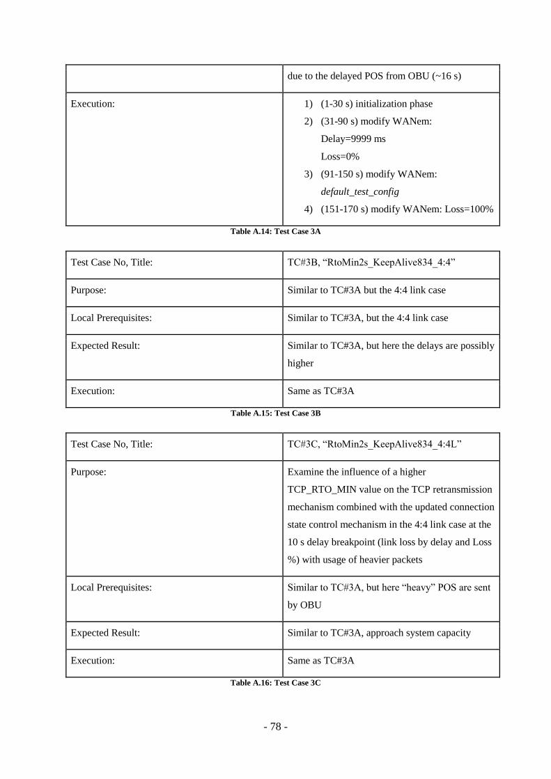
- 78 -
due to the delayed POS from OBU (~16 s)
Execution: 1) (1-30 s) initialization phase
2) (31-90 s) modify WANem:
Delay=9999 ms
Loss=0%
3) (91-150 s) modify WANem:
default_test_config
4) (151-170 s) modify WANem: Loss=100%
Table A.14: Test Case 3A
Test Case No, Title: TC#3B, “RtoMin2s_KeepAlive834_4:4”
Purpose: Similar to TC#3A but the 4:4 link case
Local Prerequisites: Similar to TC#3A, but the 4:4 link case
Expected Result: Similar to TC#3A, but here the delays are possibly
higher
Execution: Same as TC#3A
Table A.15: Test Case 3B
Test Case No, Title: TC#3C, “RtoMin2s_KeepAlive834_4:4L”
Purpose: Examine the influence of a higher
TCP_RTO_MIN value on the TCP retransmission
mechanism combined with the updated connection
state control mechanism in the 4:4 link case at the
10 s delay breakpoint (link loss by delay and Loss
%) with usage of heavier packets
Local Prerequisites: Similar to TC#3A, but here “heavy” POS are sent
by OBU
Expected Result: Similar to TC#3A, approach system capacity
Execution: Same as TC#3A
Table A.16: Test Case 3C
Recommended